Search the Community
Showing results for tags 'capstan'.
Found 7 results
-
 This will be my take on the NRG's capstan project, sold as a set of plans to help modelers learn and practice scratchbuilding skills: The project can be completed in Advanced or Intermediate mode, depending on the level of tools and skills the builder has. There are three build logs for this that I've found; the original by @tlevine, one underway by @gjdale and one completed by @usedtosail. If I've missed any, please let me know! My build will differ from those above in three ways. First, I'll be following the Intermediate instructions whereas the other two are Advanced, so hopefully this will be helpful for others interested in that track. I have a Byrnes table saw but not the higher-end mills and other power equipment needed for Advanced. Second, the assumed scale for the project is 1:16 and the builds above are all in that scale, though the instructions encourage builders to consider other scales as learning to read plans and convert measurements is part of the project's goal. So I'll be converting mine into 1:24 because I want to display it with two 1:24 Model Shipways naval cannon dioramas I've built previously: Third, I'll be milling my own wood from material I've logged, milled, and cured on my homestead here in rural Missouri. I'll be using maple, cherry, and walnut, producing a similar color profile to my recently completed NRG half-hull planking project: Hopefully these differences will make this build unique and useful to others considering this really cool project. Thanks to the NRG, and especially Toni Levine, for putting this together.
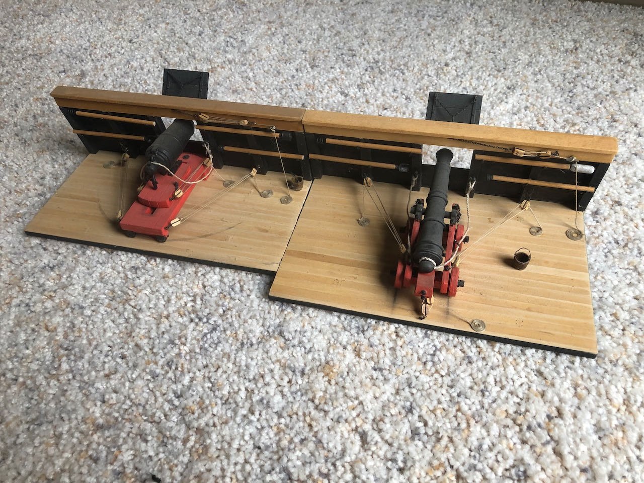
- 69 replies
-
- 10
-

-
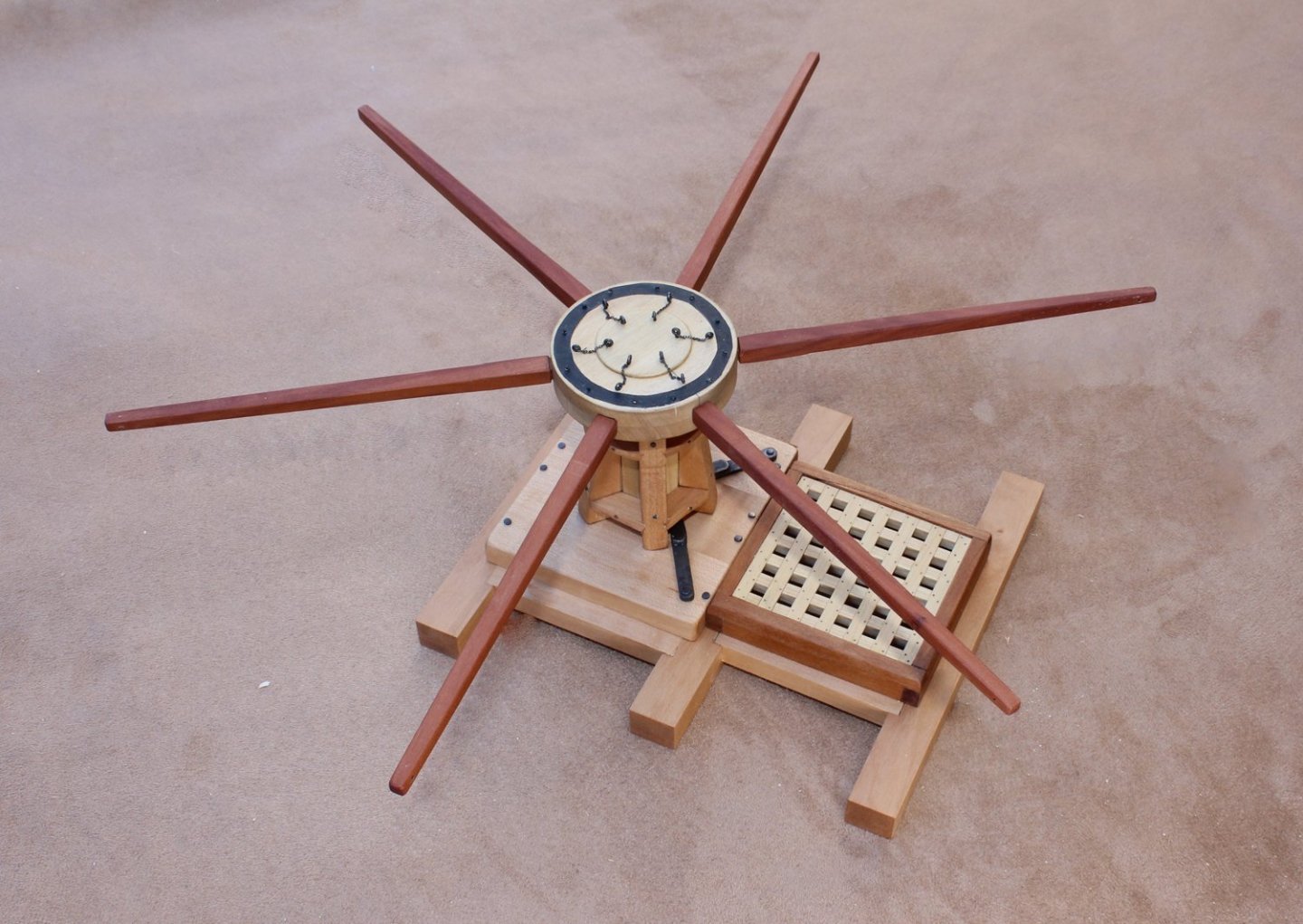
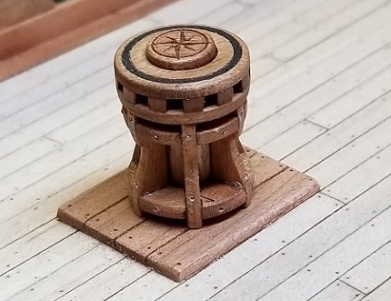
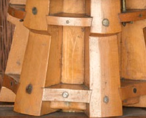
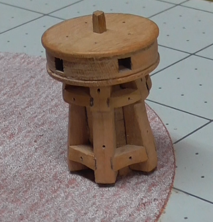
Two years ago, the Guild started selling the half hull kit, a project designed to include modelers who had no access to power tools. The purpose of the kit was to teach modelers how to plank a hull by spiling. The Guild has a new project, actually two projects, designed to expand your modeling skills and develop confidence in the step towards scratch building. As you know, the Guild’s logo is a capstan. Our next project is construction of a capstan, shown on its step, with a hatch and grating. The first project is designed for the builder whose only power tools are a Dremel-type rotary tool and a hobby circular saw. The second is for the builder who has all the “toys”, including a lathe and mill. This is a picture of the completed intermediate-level capstan. Because this is an introduction to scratch building, the project will be sold as a download which will include a monograph and fully dimensioned plans for both the intermediate and advanced projects. No wood is included. The builder will choose the scale of construction and develop their own lumber list. Most of the plans are drawn at a scale of 1:16 (3/4 scale). At this scale, the completed model measures approximately 6” x 6” without the capstan bars and 12” x 12” with them installed. Let’s get started…
- 65 replies
-
- 20
-
-

-
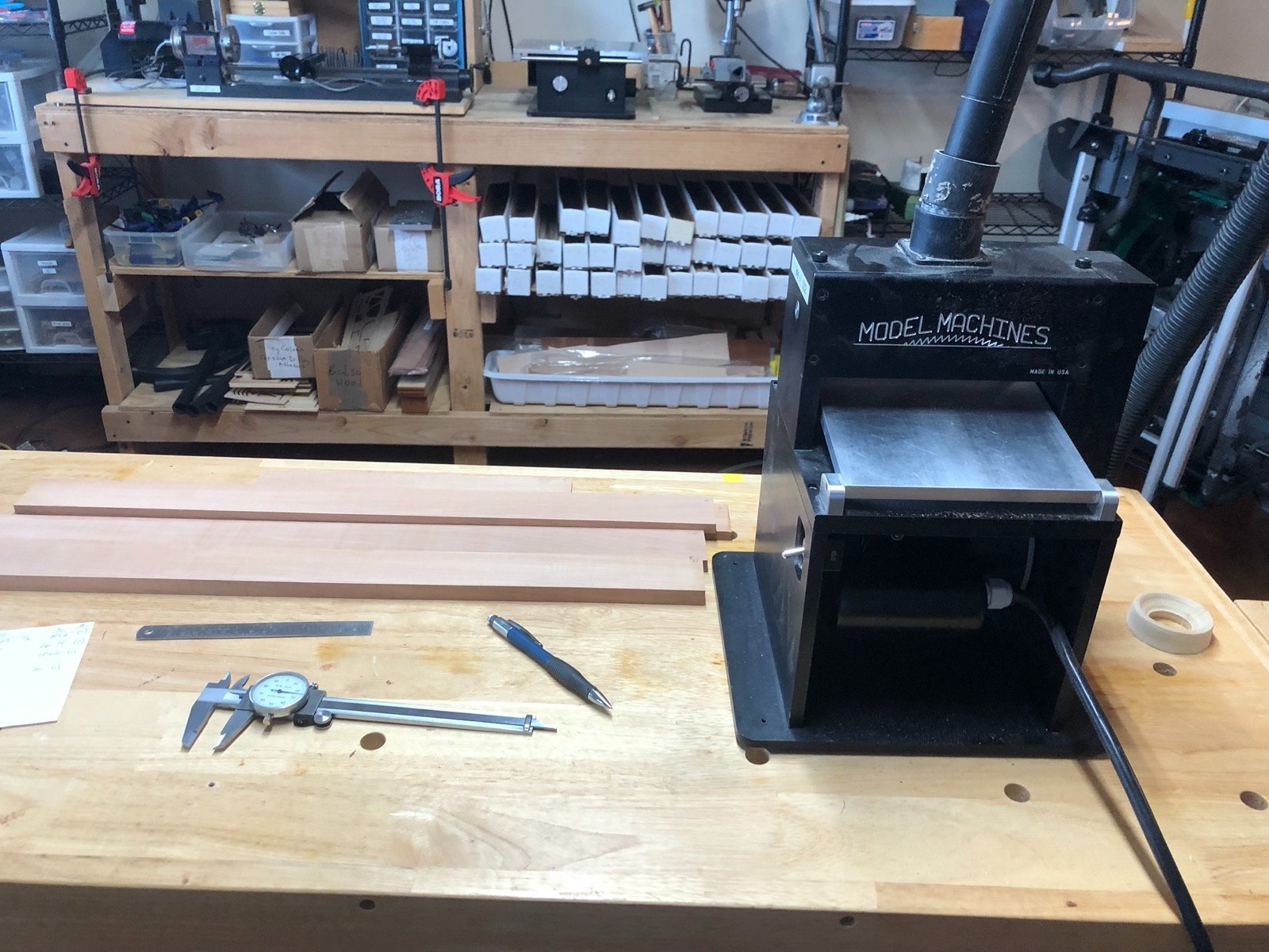
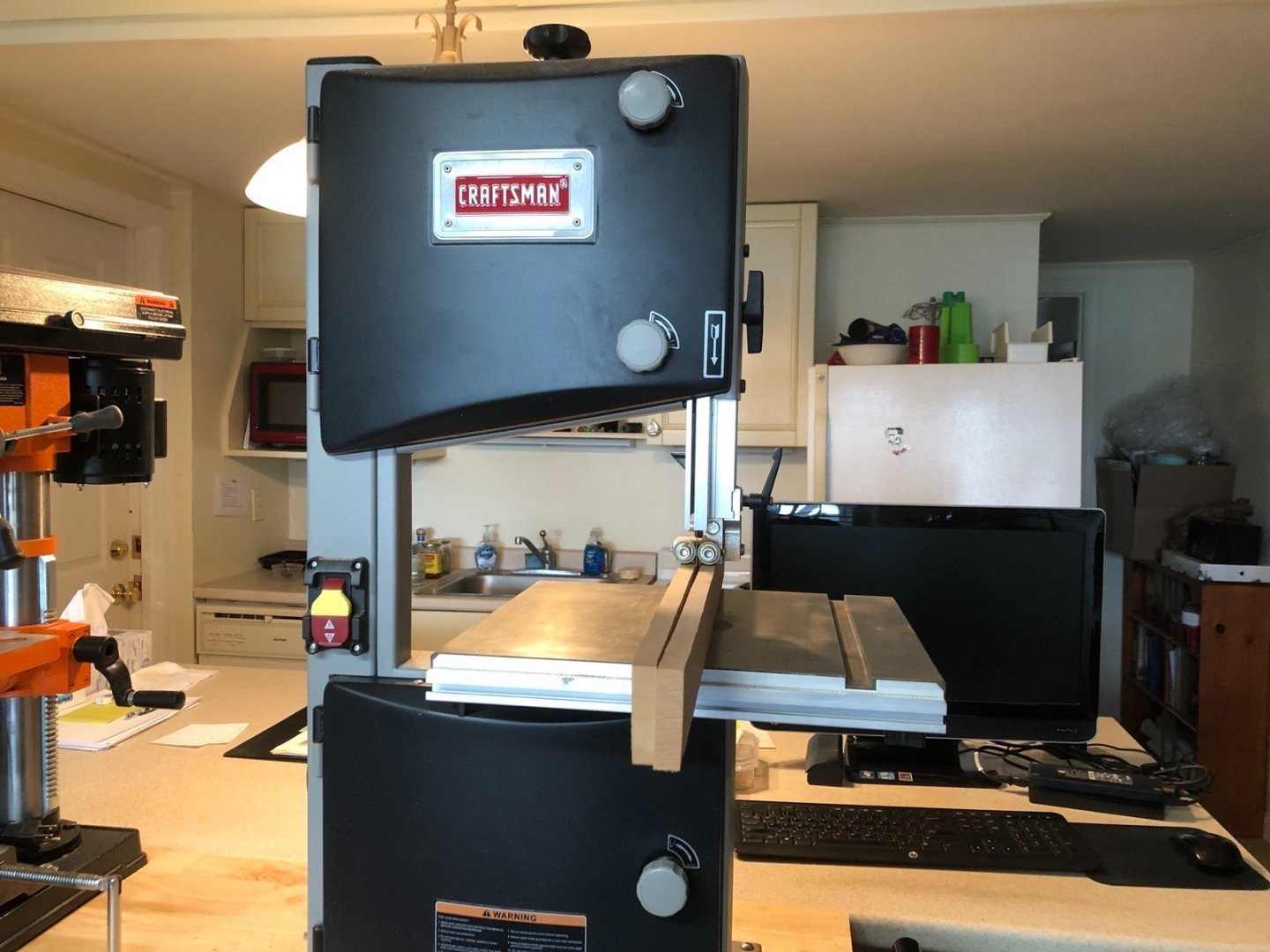
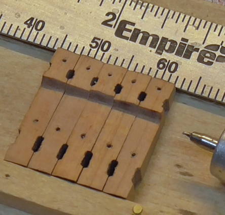
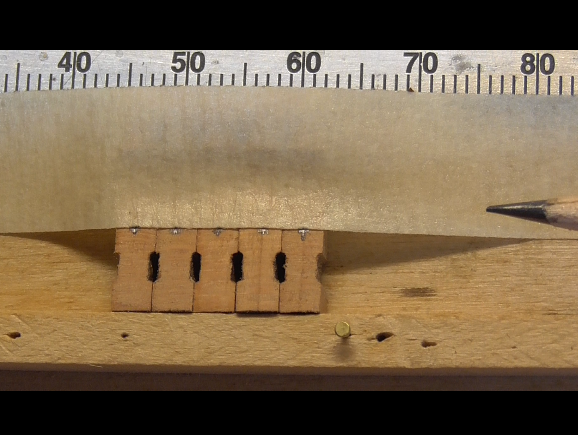
 So I am between ship models but we are having a pretty crappy Summer weatherwise so far so I decided to try my hand at scratch building the capstan model from the NRG plans and instructions by Tony Levine. I have the tools so I am going to try to build the Advanced version of the model but may drop back to the Intermediate version if I am having trouble. I downloaded the instructions and plans from the NRG site and printed it so I have it all in front of me as I go. I started the build by rough cutting sheets of pear wood from a billet I had in scale 10", 7.25", 6", and 5" thicknesses on my small band saw. I already had a 4" thick sheet. I had gone through the plans and found these to be the thicknesses needed for the majority of the parts. I do have some boxwood that I may use as a contrast but for now everything will be pear. I then ran the sheets through the course side of the thickness sander until I had the saw marks out and then through the fine side until I had the correct thicknesses. I imagine this is pretty basic stuff for you scratch builders but this is the first time I have started a scratch project. The next step will be cutting strips from these sheets for the beams and carlings.
-
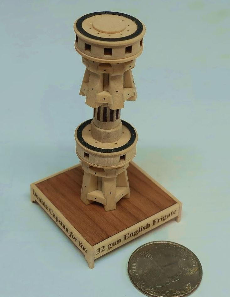
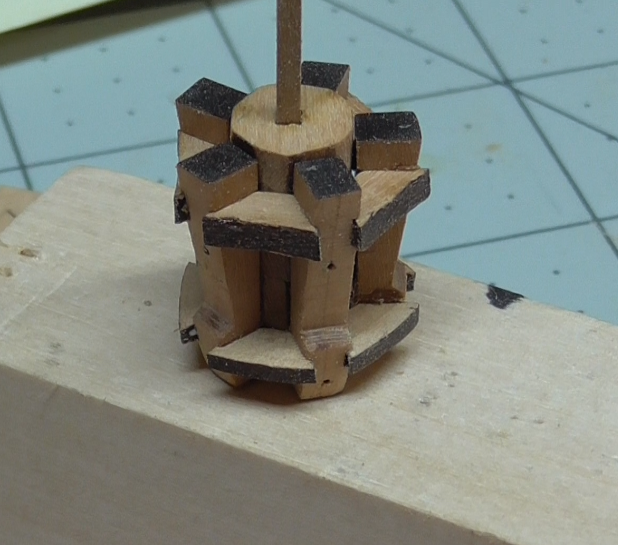
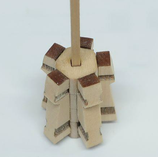
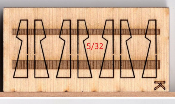
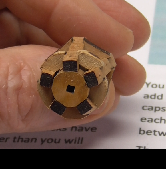
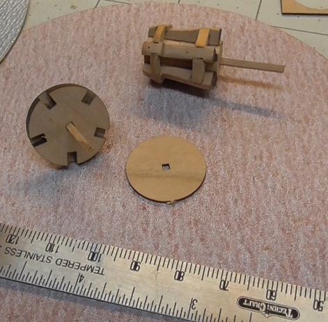
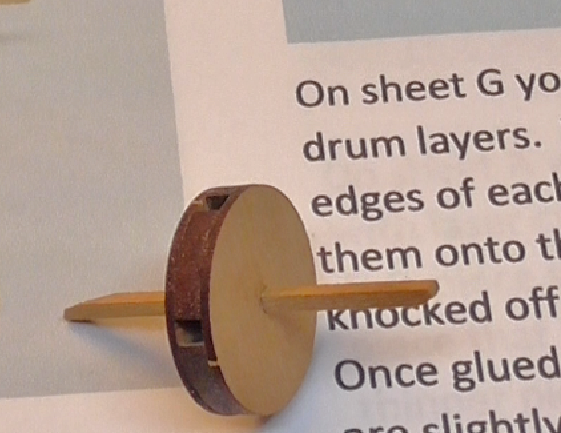
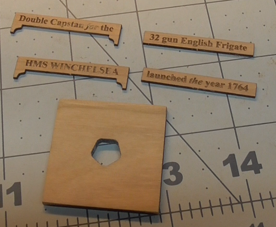
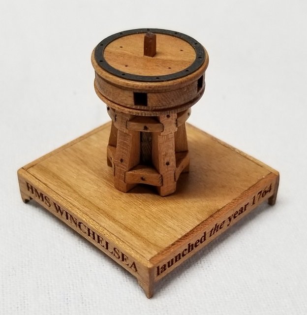
 I recently reviewed this kit over in the Reviews forum: 1:48 Double Capstan for HMS Winchelsea I discussed it with Chuck, and he felt this forum would be the best place to put my build log. First, a little background about why I am building this capstan even though I don't foresee building Winchelsea. Back in June of last year I posted an item about the capstan I built from scratch, for my Corel kit Resolution. I thought it was pretty decent and as good or better than a lot of kit provided or third party parts. ( I had actually upsized the 1:72 kit from Master Korabel ) I'm glad Chuck looked in on my log, because he pointed out how kits rarely get the relative size ( thickness ) of the various parts; whelps, chocks and etc. of a capstan correct, if even close. It requires several thicknesses of wood, and therefore drives up the cost of the kit/part.. He showed me a picture of this model: ...And I decided at that point, that my model would never launch with the sub-par capstan that had been delivered by the contractor. Fast forward six months and Chuck unveils the capstan mini-kit for the Winchelsea project. I knew right away that Chuck had saved me the trouble of designing my own new capstan. I waited a couple of weeks to order my kit/s so that the Winchelsea project participants would have first option to get their kits. The packaging is typical of Syren mini kits, and the detailed instructions are available for download at Syren. This is the Cherry version. It will fit in with my Resolution. I also ordered the Alaskan yellow cedar version for another project I have in mind. The kit has 7 different thicknesses of wood as well as some black monofilament and black laser board pieces for detailing. I recommend keeping the various parts in their sheets until called for in the instructions. Many are similar and i know I would be scrambling to find the right part if I had removed them all early on. The first step calls for building the central column of the lower capstan. The instruction are very precise in describing which parts are needed for each step and which sheet to find them on. Example: Glue one ¼” thick column section along with three 3/16” Column sections together after sliding all of them onto the 1/16” strip. These column sections look like five sided pieces. The ¼” piece can be found on sheet A. The 3/16” pieces can be found on sheet B. There are relatively few steps, covered in eight pages of instructions, but each step involves several pieces. The next step calls for putting the lower whelps on the center column. Each step has information about when and how char should be removed. Naturally we want it removed from surfaces that will be visible after assembly. The lower column has five flat surfaces to receive the whelps, and there will be a small visible strip between each whelp. I over-did the char removal a bit here and paid for it later. The cherry has some dark streaks that can be a little confusing when removing char, so I would keep this in mind throughout a cherry build. Also, the AYC may be a little less forgiving when it comes to sanding, so a little extra care may be required there. Looking ahead, I chose to drill the holes for the simulated bolts before assembly. This is an image from the instructions. It calls for gluing the whelps on to the column in preparation for adding the chocks. I ran into some problems here, because I think I over-sanded the column, and did not get a tight, even spacing of the whelps. So I added the chocks at this point to help me align things before the glue ( PVA) set, and did the best I could to even things up. I had intended to drill the detail holes in the chocks before assembly, but my botched efforts got in the way.. You can see some gaps at this point, but I managed to recover somewhat, and I think you will see the final result with the lower capstan doesn't look too bad. I don't plan on using the lower part, so I am depending on it more for a learning process. At this point, I want to elaborate on those grooves for the chocks in the whelps . Looking back at the model I posted earlier. Note the chocks in the grooves. You will find those grooves in some plan drawings from the NMM. Structurally, they make sense. You won't find those grooves on any other kit model of a capstan. ( that I am aware of ) When Chuck chose to include those grooves in this kit he took laser part making to another level. It created a lot of additional work in cutting the parts. The grooves had to be etched precisely on both sides of the sheet, unlike cutting, or engraving on one side. The piece would have to be flipped and placed with pixel level preciseness to make this happen. Probably, once he had it all planned he created a jig that enabled him to more easily repeat the process, but getting there would have taken many hours and lots of scrap.. When all is said and done, those grooves really contribute to a realistic and more precise build. I ended up with some ugly gaps, but I hope to show I overcame them to some extent later. Just something for other builders to keep in mind. Next is building the drum for the lower capstan. Really an easy process of making a sandwich of three parts. Char cleaned off and added to the assembly.. I won't go over the detail of putting the base together. It is really straight forward. The biggest challenge is getting the words in the right order.. A little polly to bring out the cherry, and here is my version of the lower capstan. I have continued working on the upper part, which i plan to use for my Resolution, and should have it completed shortly.. I hope to be able to show a little improvement with my lessons learned..
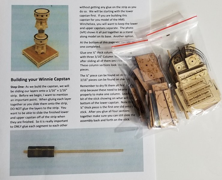

- 8 replies
-
- 6
-
-
- syren chuck
- winchelsea
- (and 1 more)
-
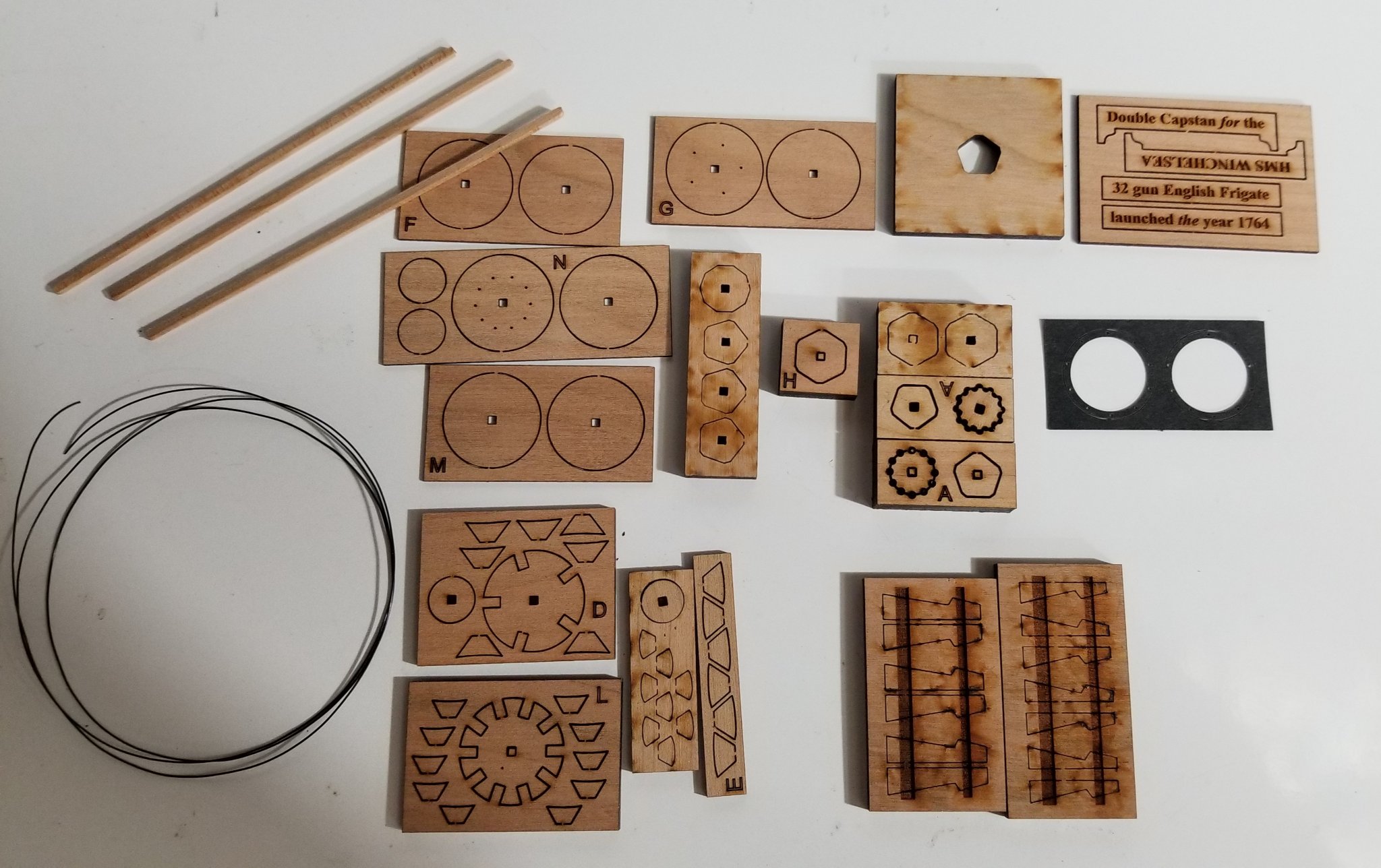
I feel fortunate that I am able to be the first to show off this beautiful little kit from Chuck and the Syren Ship Model Company I know quite a few Winchelsea builders already have this, because I had to stand in line for a couple of weeks to get mine. Here is the no frills packaging ( I ordered one each of the cherry and Alaskan yellow cedar versions ) next to the comprehensive assembly instructions, available for download at Syren. Winnie Capstan Instructions Here is the cherry version spread out. The wood is as high quality as I have ever seen. It reminds me of pear, in that there is very little noticeable grain. However, having worked with a lot of cherry lately, I look forward to the color I know will pop out with a very light finish. Chuck has provided five different thicknesses of material, from 1/32" to 1/4". The attention to detail is what you have come to expect from Chuck and Syren, with the included black monofilament to simulate bolts and the black laser board ring detail. There is just nothing else out there, kit or molded, to compare to the realistic look of this kit. Sure, we might see a 3D printed one any day now, if they are not already out there, but they will not be wood, and we will know it.. I can't imagine how Chuck found the time to design this and bring it to production. He never sleeps. At $23.00 it is a steal.. It will be a great addition to any 1:48 project, and in an historically accurate way. The design and look of these things did not change much over a 100+ year period. I don't have any plans to build the Winchelsea, but I have a couple of projects in mind where this kit will fit right in. The quality and completeness of the kit is fairly self explanatory, so I don't know what else I can say at this time. Please hit me with any questions you have. I plan on putting it together in the next few days and will create a build log to document the experience. I hope I can get close to the bar Chuck has raised.
- 4 replies
-
- 13
-
-
- capstan
- winchelsea
- (and 3 more)
-
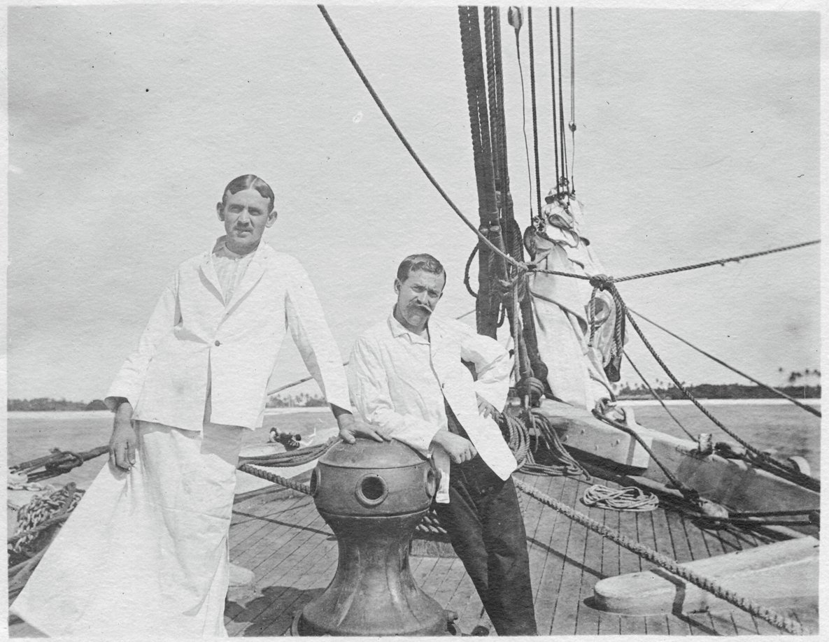
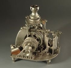
 Hello, All. I've been searching for any plans/photos/schematics of a Hyde Windlass Company (HWC) hand capstan and windlass assembly. This would be sized for a 350-ton sailing merchant around 1890. The brigantine Galilee was launched in 1891 in California and seems to have been equipped with a Hyde capstan (see the photo below). Photo courtesy of the Department of Terrestrial Magnetism, Carnegie Institution, Washington DC (c. 1907) (The attire of the men is somewhat strange. The research crew's surgeon is on the right and his steward/surgical assistant is dressed for surgery.) What I really need is some information about the windlass, which was located in the open forecastle under the deck. I would like to render this equipment as accurately as possible, since it will be visible in the finished model. An entire windlass/capstan assembly has been modeled; its images are available on the Web. However, all that i have been able to find are steam windlasses, like the one shown here. Galilee's windlass was strictly manual. I have already contacted the Maine Maritime Museum in Bath, ME. They have some extensive archives pertaining to the HWC (which became the Bath Iron Works Shipyard), but their staff is limited and they haven't been able to find what I need so far. If any members live in or near Bath and would like to look into this, I would be very grateful. Terry
- 21 replies
-
- 2
-
-
- capstan
- hand windlass
- (and 3 more)
-
 I'm contemplating Le Renard (AL) as my next build but am puzzled by one feature (or lack thereof). The anchor cables disappear into the hull at around deck level on the illustrations I've seen but there is no sign of a windlass or capstan on deck. As a cutter of around 68 tonnes would she have had a tween decks capstan? Crew seems to have been 60 so I guess that below decks space would have been at a premium with a rope locker and probably galley stove as well all situated at the fore end of the ship. Comments anyone? Rick