Search the Community
Showing results for tags 'chaloupe'.
Found 3 results
-
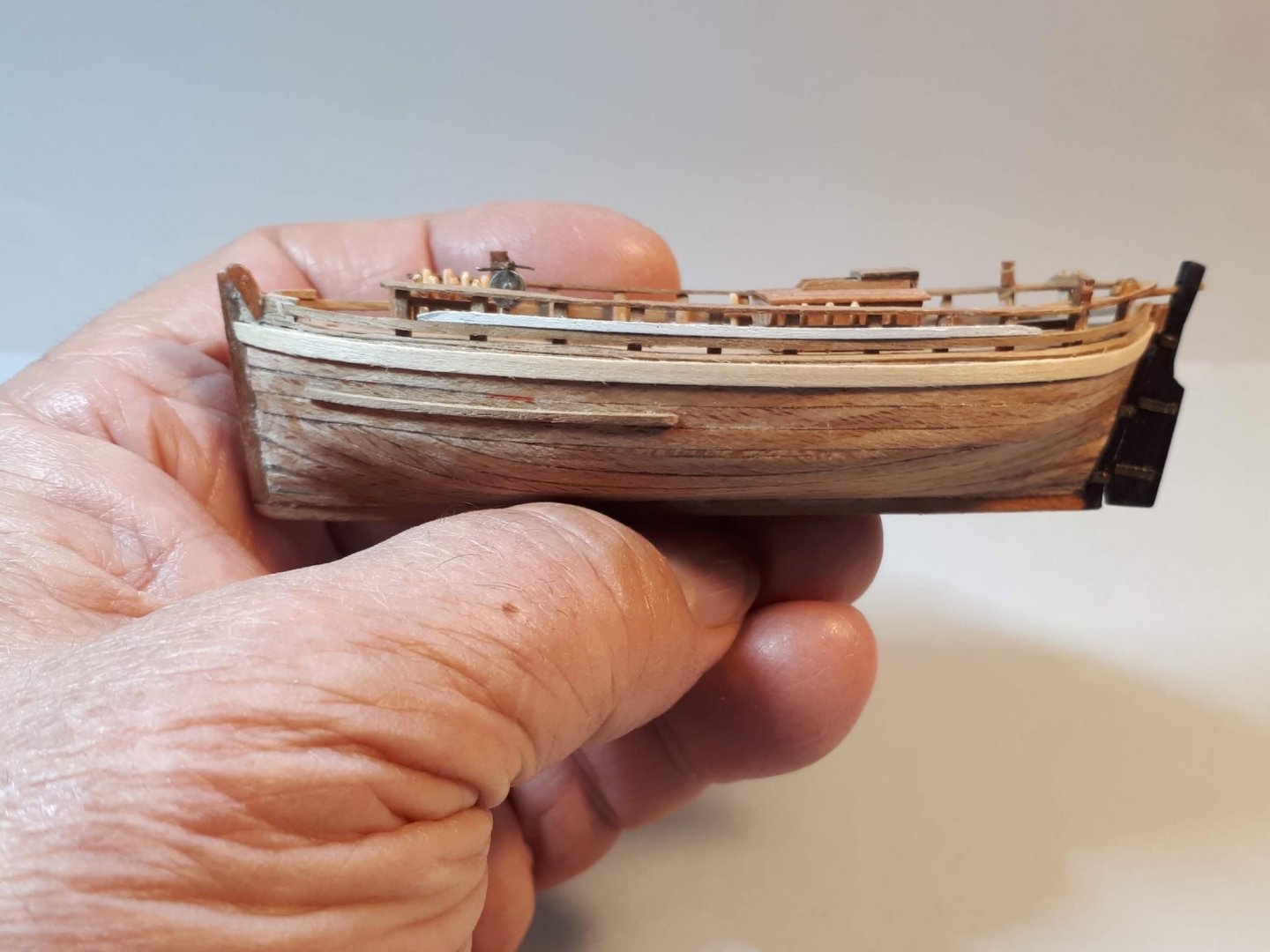
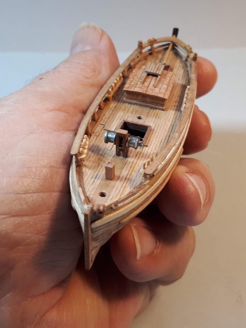
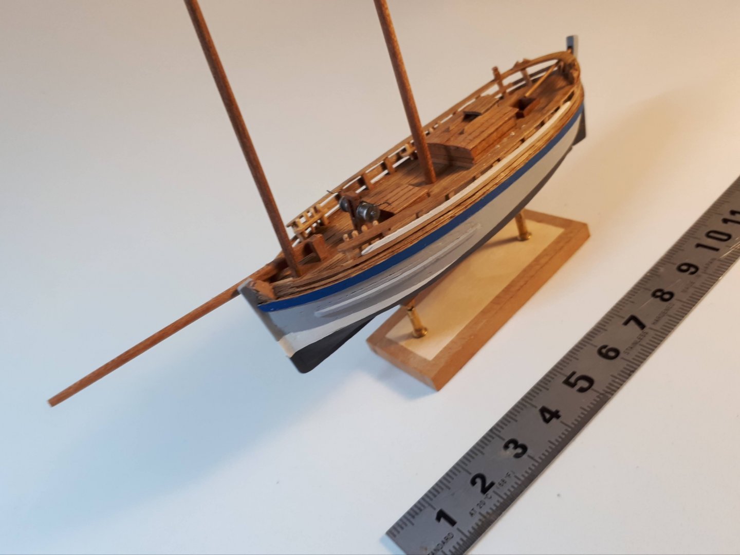
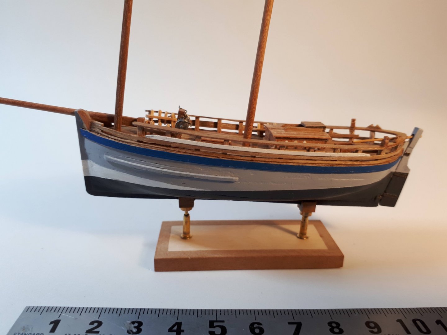
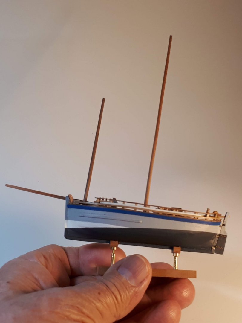
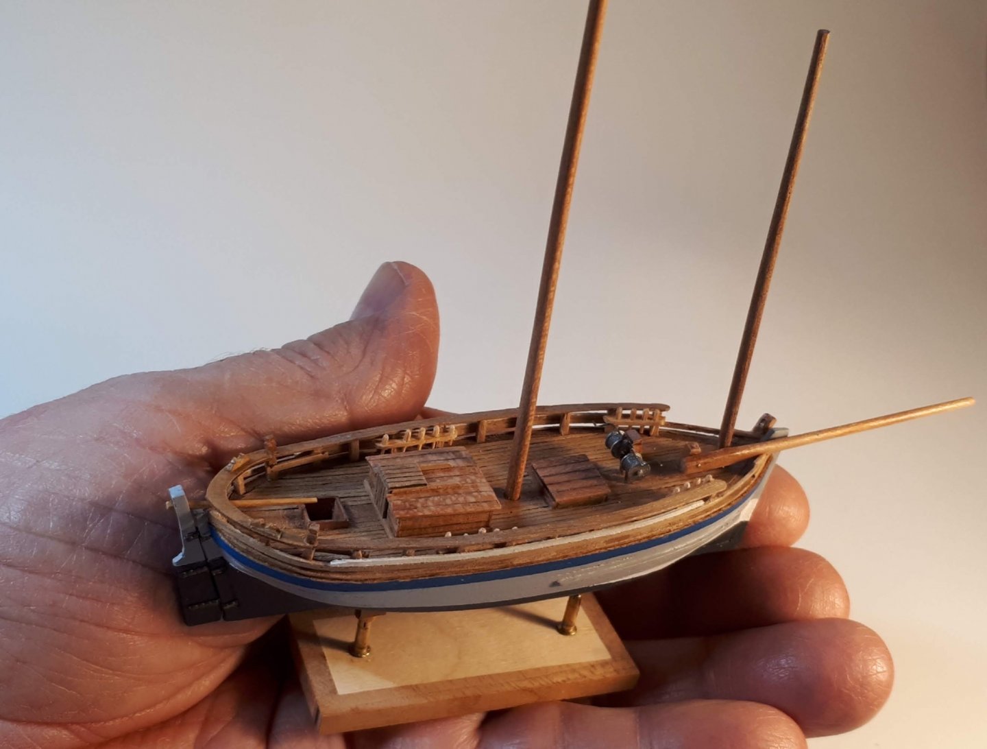
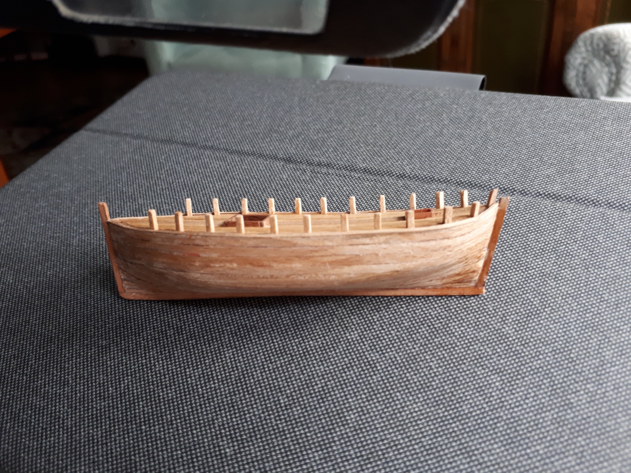
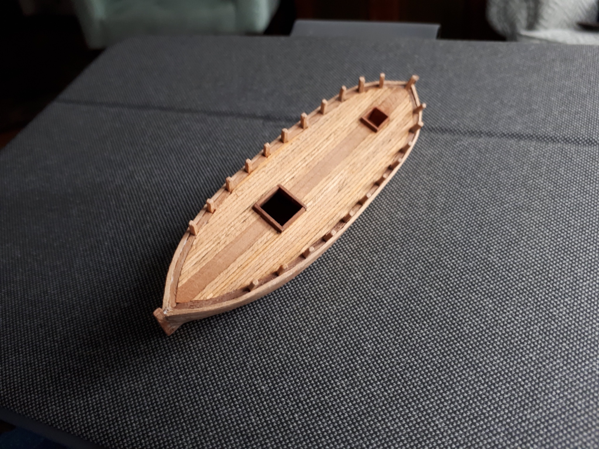
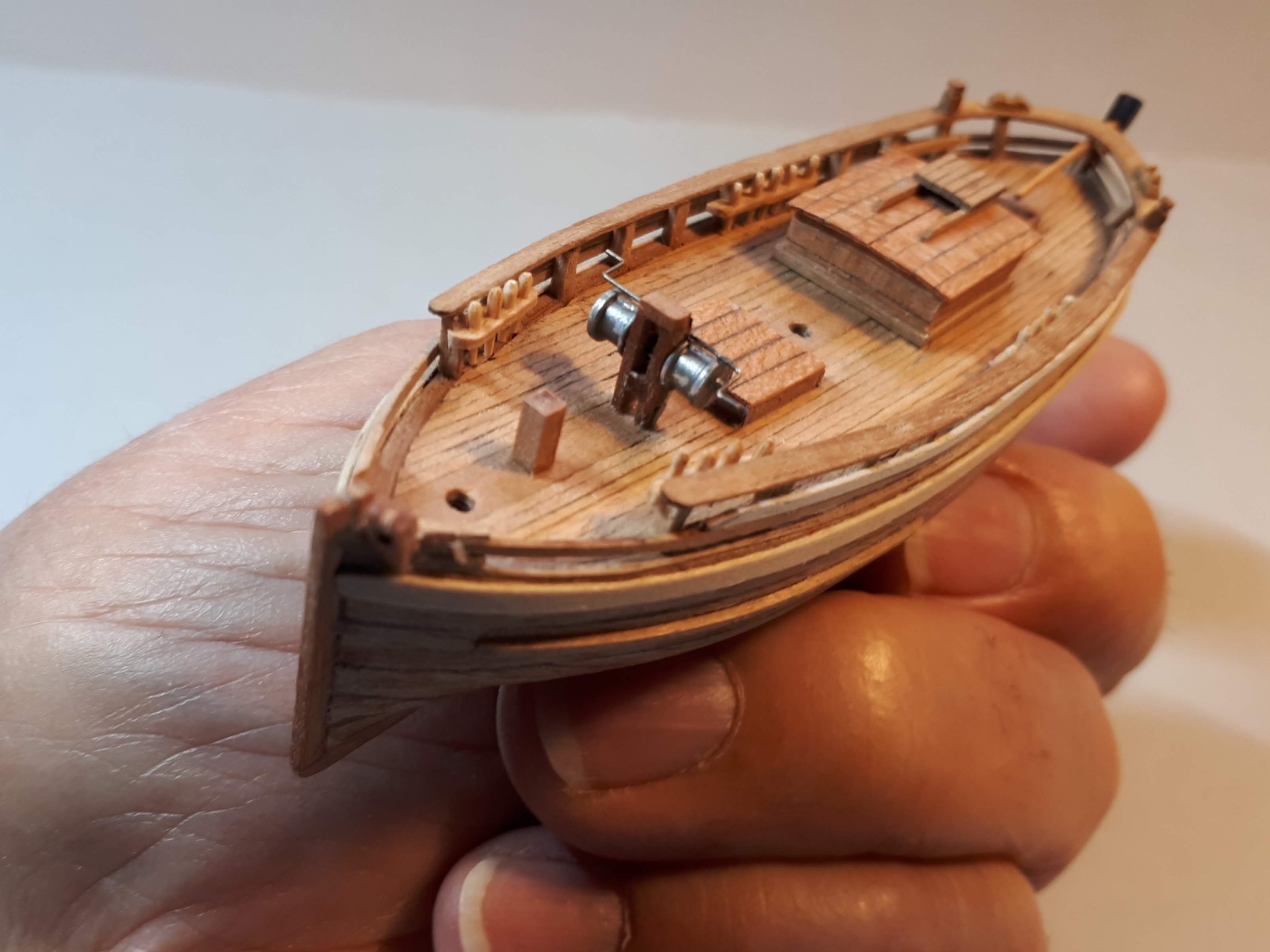
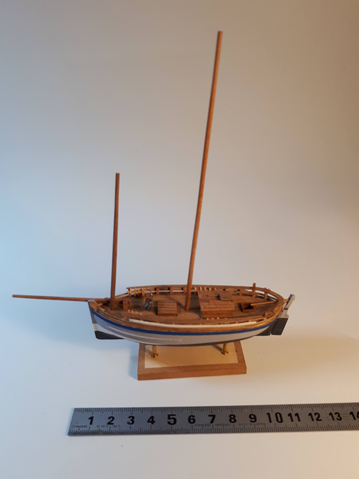
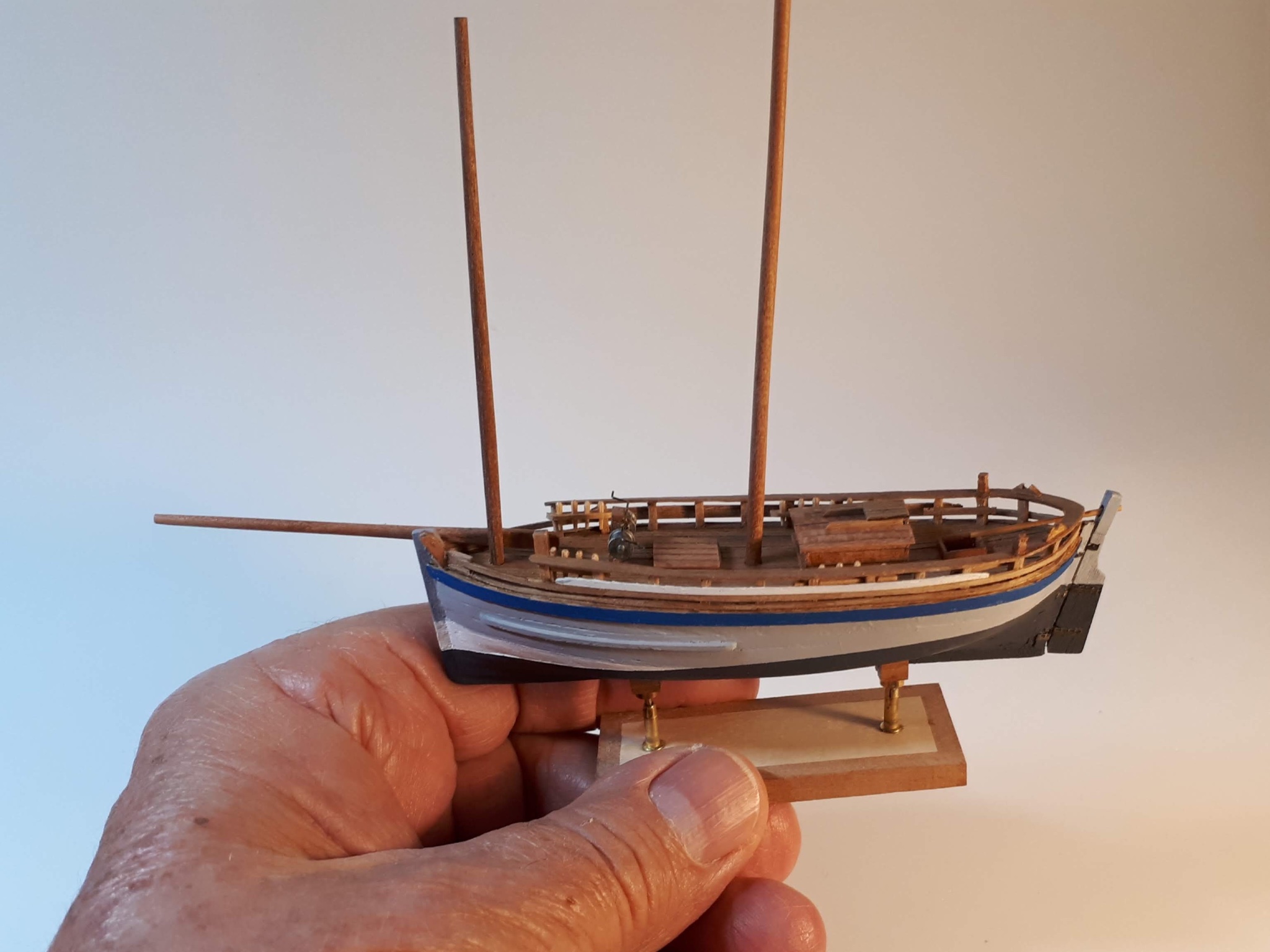
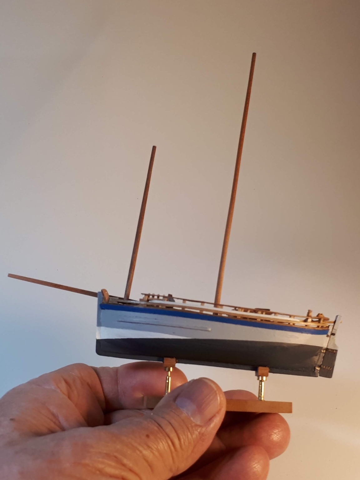
 I present a new model, although it is true that with its already advanced construction process. As I made the hull using my usual technique, which I have shown on the forum several times, there is no photo of this part of the process. It should also be noted that the masts are only presented and are not final, neither because of their length nor because of the inclination with which they appear. And now, by way of introduction, a brief historical overview of this type of boat. Until the end of the 19th century, in the region of Port-Louis, in Brittany, coastal fishing for roe sardines practiced in good weather was supplemented by winter trawling of other larger species. This task was carried out with solid open boats, of about 10 m. in length and 2.80 m. wide, with a draft of 0.70 m. The winter sea conditions are harsh in these waters, which makes it very difficult to work in the open air on these open boats, which is why, in 1882, a boss from Lorient took the initiative to equip his boat with a temporary deck, which is armed against winter and disassembled in good weather. In turn, as coastal fishing became more and more scarce, fishermen went deeper and deeper into the open sea, and soon these removable deck boats began to be used for trawling in rougher waters, for which they did not present the adequate nautical characteristics. For this reason, in a short time the deck boats evolved, with a permanent deck, but they were made with the same shapes as the large open boats, retaining their main U-shaped section, but providing them with a planking above and solidly decked, fitted with a windlass and higher masts, so all the weight was added at the top and had to be balanced with ballast. But the maintenance of the main U-shaped section prevented placing this ballast (essential in a trawler) sufficiently low. In addition, the righting moment of a hull of this U-section has a high initial stability which decreases very quickly with pronounced angles of inclination, which makes these ships very sensitive high waves and sea blows. These decked boats, with an elegant appearance, showed that their nautical qualities were not adequate for the conditions of navigation on the high seas. Between 1891 and 1900, eleven of them were shipwrecked, resulting in the stoppage of their production and their replacement by small dundées, which prove to be much safer.
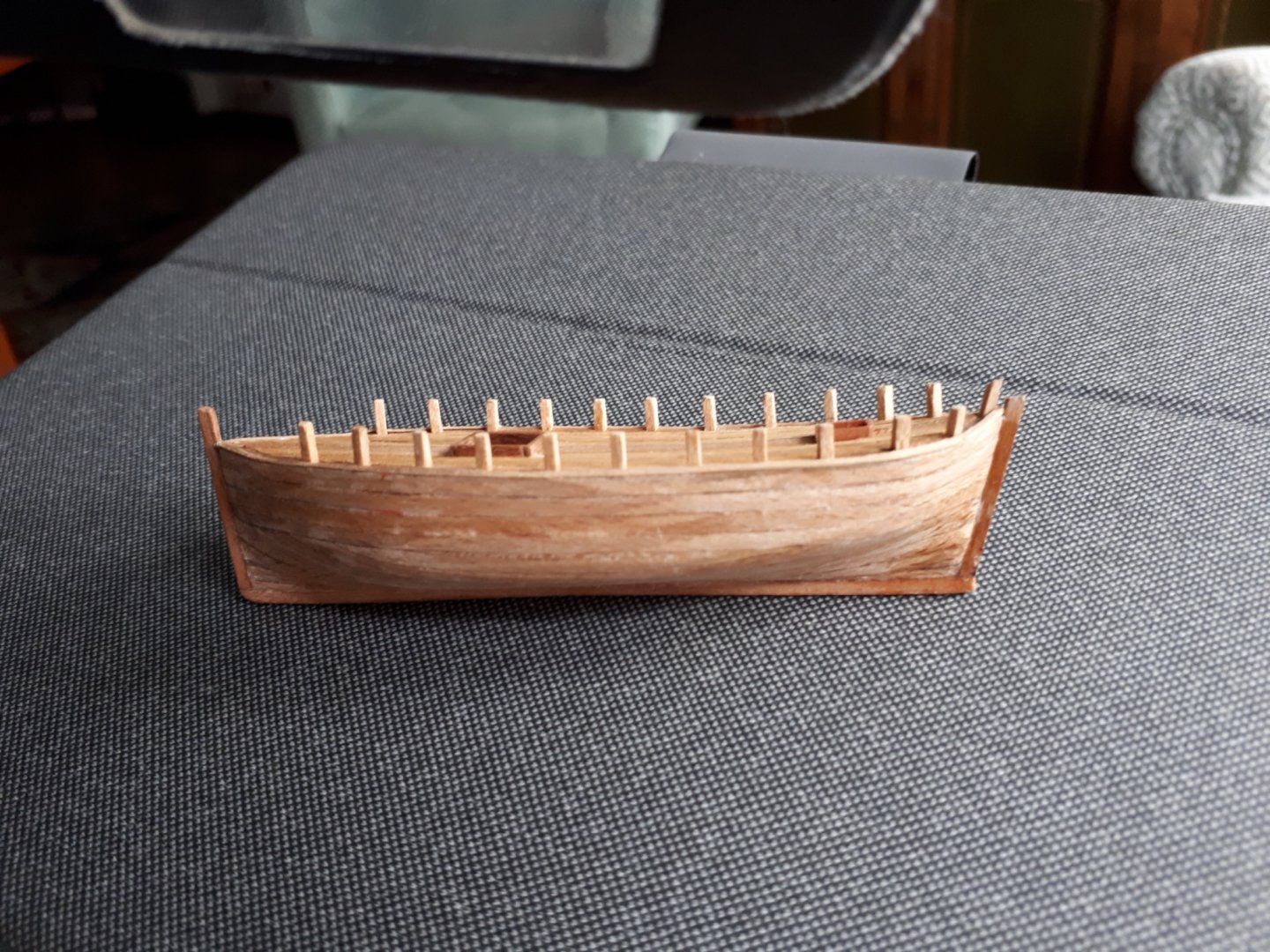


- 15 replies
-
- 18
-

-
- fishing boat
- small boat
- (and 1 more)
-
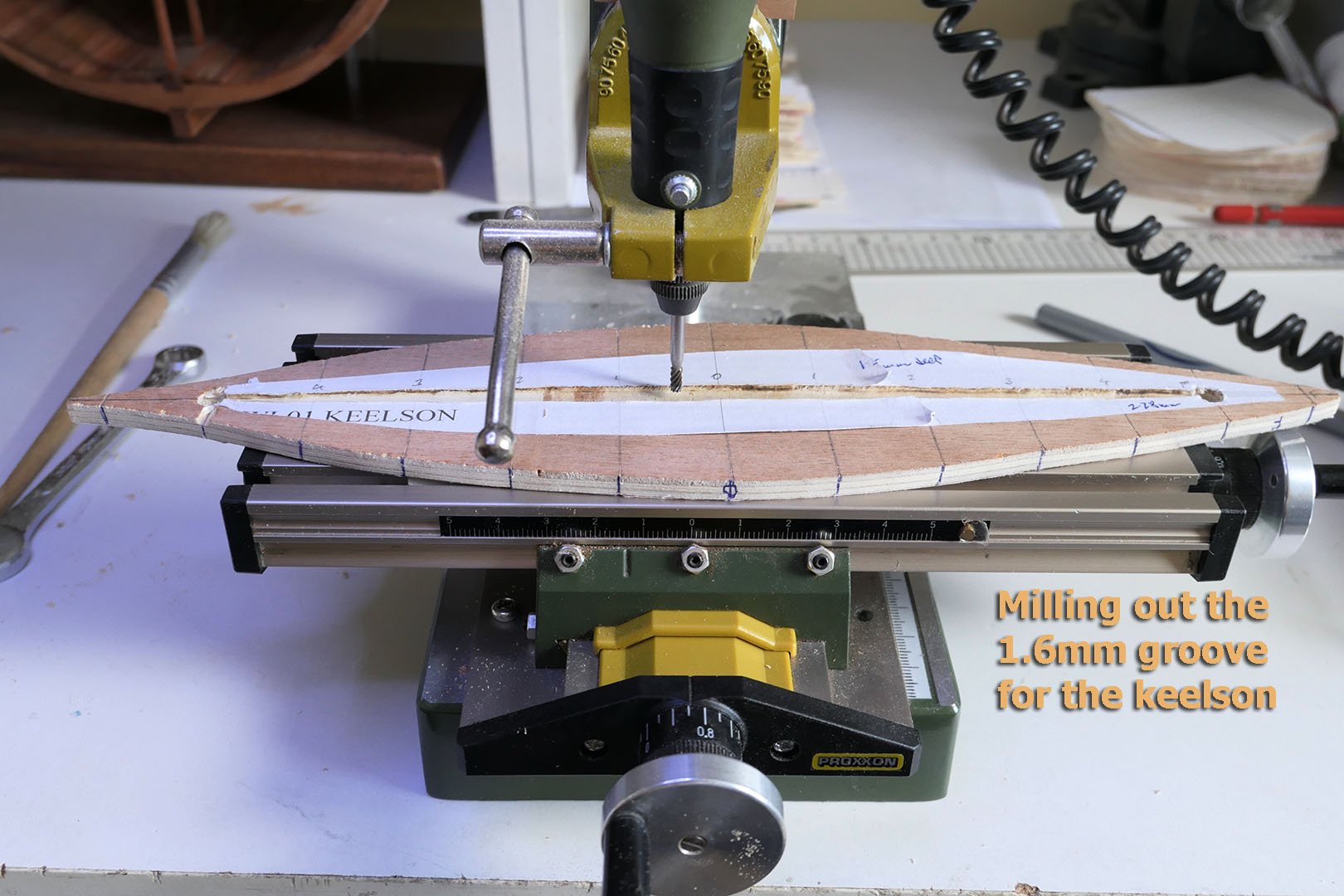
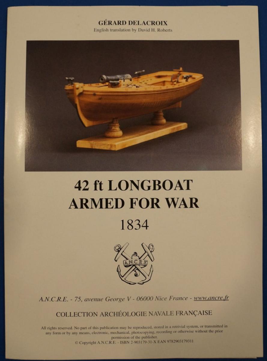
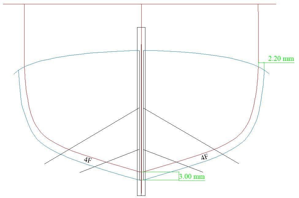
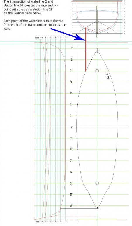
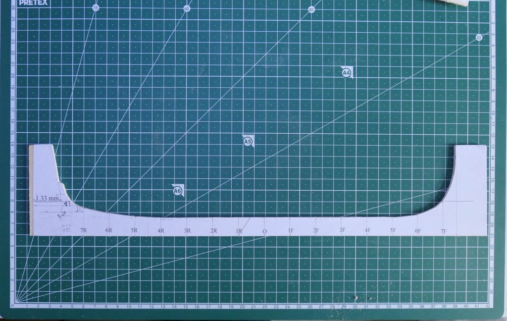
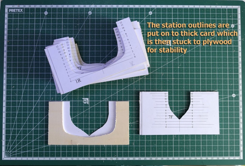
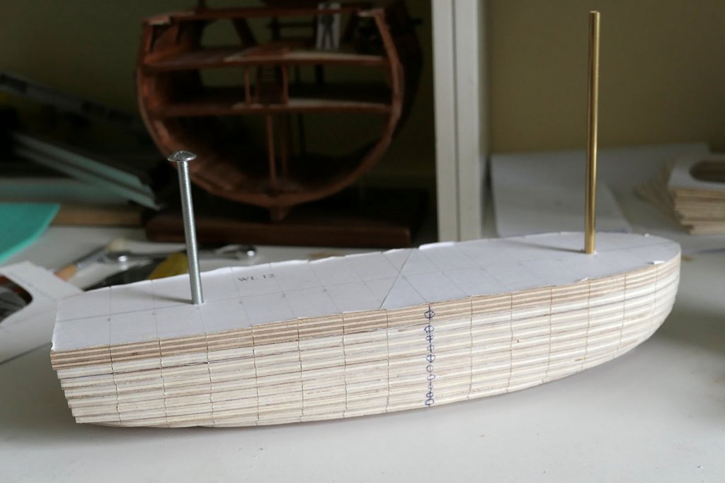
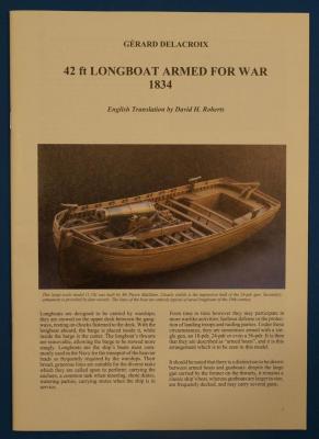
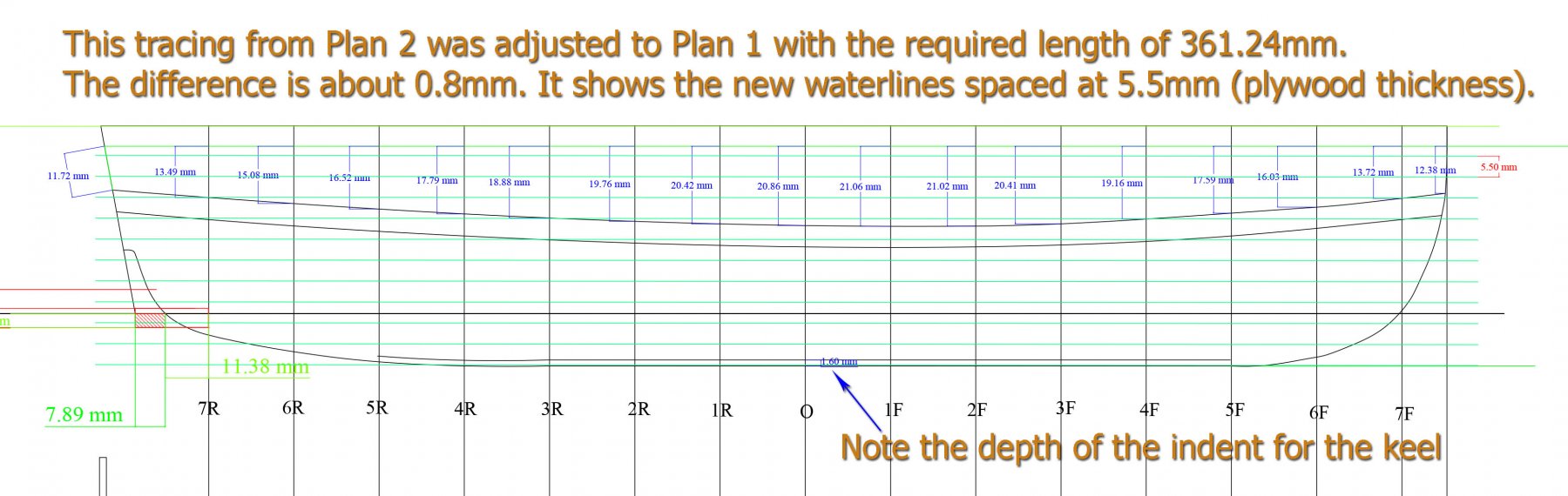
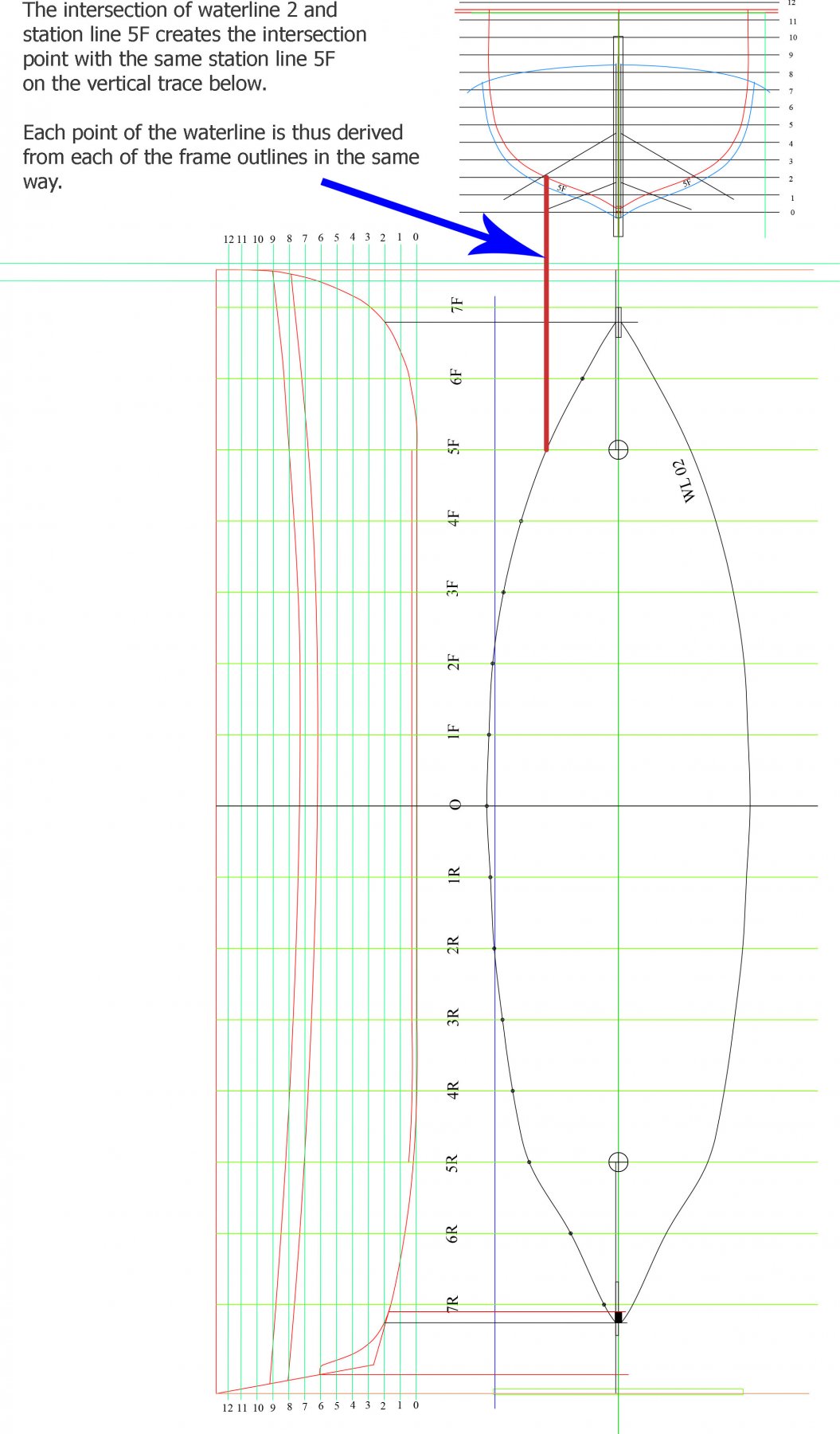
 INTRODUCTION AND OTHER BUILDS In June 2017 I was considering what to build next. The main criterion was to keep learning but with a different type of boat and a different type of construction. I tinkered with the idea of La Jacinthe, Le Rochefort, and even thought of embarking on Ed Tosti’s plans for the Naiad. However I thought a logical next step would be to go for a longboat using a mould as construction type. So I started on Gérard Delacroix’ plans for the French armed longboat of 1834. The plans for this are available in several languages from Ancre at https://ancre.fr/en/monograph/31-monographie-de-la-chaloupe-armee-en-guerre-1834.html. As stated in the English translation of the introductory manual, the model is “based on a draught in the 1834 Atlas du Génie Maritime (Folio of the Corps of Naval Engineers). The longboat, at 42’8” long, is of imposing dimensions, being large even for a ship’s boat: a man standing on the bottom boards would have the thwarts at chest height.” This type of boat was used for the transport of the heavier loads required by warships and diverse tasks including carrying of anchors, shore duties, watering parties and carrying stores when the ship was in service. They could also participate in harbour defence and sometimes were armed with a single gun as well as several small cannon. There are several excellent builds that can be seen on the internet. The place to start, of course, is with the forum devoted to this model on Marine & Modélisme d’Arsenal at http://5500.forumactif.org/f83-la-chaloupe-armee-en-guerre-1834-plans-gerard-delacroix. There you can find a general discussion about points of interest that people come across while building the model as well as several builds. Very few of the builds go into the details of how they overcome problems as they come across them. However one in particular has gone to great lengths to detail each step of the construction. This is the build by Jean-Jacques Herault, which you can find starting with an index to the build at http://modelisme-arsenal.hlt34.fr/journal_de_la_chaloupe_armee_007.htm. All these builds are in French only. For builds in English, though, there are several on this forum: · Jeronimo’s build at https://modelshipworld.com/index.php?/topic/497-chaloupe-arm%C3%A9e-en-guerre-by-jeronimo-1834/#comment-5561. (Just pictures, no discussion of techniques). · Aykut Anşin’s at https://modelshipworld.com/index.php?/topic/5550-chaloupe-armee-by-aykut-an%C5%9Fin-small/#comment-159523. Only shown as far as the mould, last post in Feb 2015. · Decoyman’s (Rob) at https://modelshipworld.com/index.php?/topic/4218-chaloupe-armee-en-guerre-by-decoyman-from-the-delacroix-plans/#comment-120001. Fairly full discussion but last post was in July 2015, and only as far as frames made on the mould. · Smac’s gallery of the completed build at https://modelshipworld.com/index.php?/gallery/album/109-chaloupe-armee-en-guerre-1834/. · Blockplane’s (Chris) at https://modelshipworld.com/index.php?/topic/14743-1834-42ft-longboat-armed-for-war-by-blockplane-scale-136-first-time-wooden-boat-build/&. Complete, last post in May 2017. There is in addition a very useful series of 11 videos of a complete build (called Chalupa Armada) by Nacho Gomez starting at https://www.youtube.com/watch?v=HlUJabWYFTY. Each of these is over an hour long and is a useful reminder of how to use basic hand tools. All are spoken in Spanish, but even if you don’t speak Spanish the videos are almost self-explanatory. No doubt there are excellent builds as well in the Russian, Polish, East European and Japanese forums, but as I don’t speak any of those languages I simply have not researched them. If anyone does know of such other builds I’d be grateful to add them to the list. MY AIMS WITH THIS BUILD LOG Clearly, with so many builds of such high quality, you’re not going to get anything classy in this build log. It is a very basic build by a novice with poor finishing and lots of mistakes and ugliness. However, as with my previous builds, these are presented as they came, with the idea that there are lots of other builders with the same lack of expertise who come across similar problems and would like to see how I might have coped with them. I also know that along the way those who are more experienced might well chip in and give words of caution, advice and rebuke. All are welcome! FIRST STEPS As usual, the first steps are to study the plans and trace them into a CAD programme so that I can make accurate copies for cutting out and for planning. I use TurboCAD, which is very low cost and which I am now used to. The next thing is to make the mould. The plans are based on making a mould from 5mm thick plywood sheets (the waterlines are space at 4.5mm). Since that size is impossible to find in the UK, I had to work out how to make it from 5.5mm sheets. That meant making the waterlines spaced at 5.5mm, and so I set about doing just that using the time-honoured method of calculating the points of each waterline from the body plans of the station lines and the station lines set at right angles. In order to do so, however, although you only need the body plan from Plan 2 for the mould to create the water lines, I thought it would be a good idea to draw the frames completely as I’d have to be doing that anyway. The way to do this is to combine the body plans from Plan 1 (which shows the station lines to the edge of the frames but without planks) with those from Plan 2 (which shows just the body plan for the mould itself, without frames or planks). The result can be seen in the following diagram of one of the frames, Frame 4F (F for Front or 4Av in the plans, for 4 Avant). This shows that the frame starts at 3mm at the keel and taper upwards to 2.2mm at its tops – but this is an issue to which I will return later when I try to correlate the suggestions in the book to use 2mm square stock for the floors and futtocks against the 3mm floors derived from the Plan. For the moment all that matters is the trace of the inner aspect of the frame to create the mould. The following is the creation of the new waterlines to space at 5.5mm, which is the thickness of the plywood I was able to buy here in the UK. You will also note the various measurements I also inserted to help with the placing of the wales and the stern timbers. With the drawing of both the waterlines and the frames completed, I could then move on to drawing the outlines of each of the waterlines for the 5.5mm plywood. The method follows the classical way of doing this, so no surprises here. A final question that I faced for the creation of the mould was how to do that from Plan 2 because the stern shown in the drawing on that Plan has a very troubling empty space. At the time I decided to just follow the sweep of the hull, but it later dawned on me that a more exact way would be to superimpose the tracing of the outline from Plan 1 onto Plan 2. That way both the line of the hull and the cut for the sternpost and deadwood would be clarified. Should I ever have to rebuild the mould I’ll be doing it that way in future. The following diagram should explain it better. Now that all the drawings were ready, I set to cutting the waterlines from the plywood and, for the keel, cutting the 1.6mm groove for the keel using a 3mm milling bit on my Proxxon drill. I’ll be showing how I made the modifications for using the drill as a mill later on in this build log. I cut the outline for the sheer view with a scroll saw and a sander on my drill. The individual stations were printed to thick card and the cards then glued to a 2mm plywood frame for strength. And at last we get to the assembly of the waterlines. The above picture was taken on the 27th July 2017, just before sanding. After sanding it down I had to put aside all modelling as we were packing up the house to prepare it for sale and spending time searching for a smaller place to move into. I’ll therefore leave this log for the moment and the next part will take it from 29th September this year when I finally was able to start work on the model again. Tony
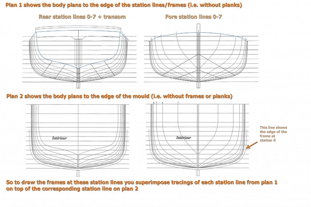

.thumb.jpg.79b3399afe366feb0b280de07fd5d8ac.jpg)

-
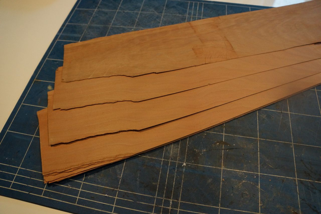
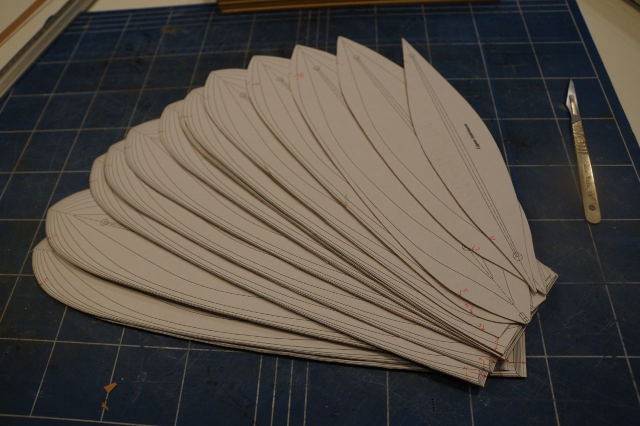
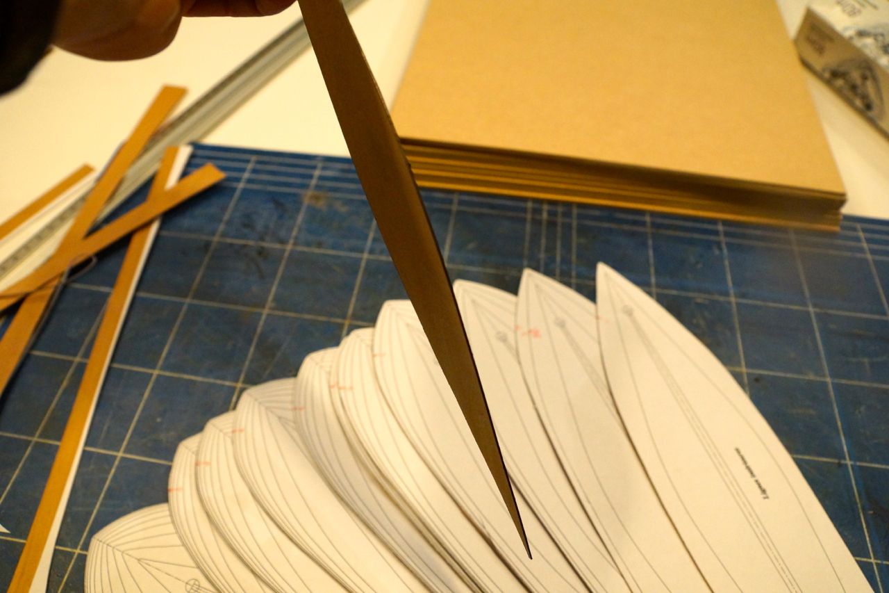
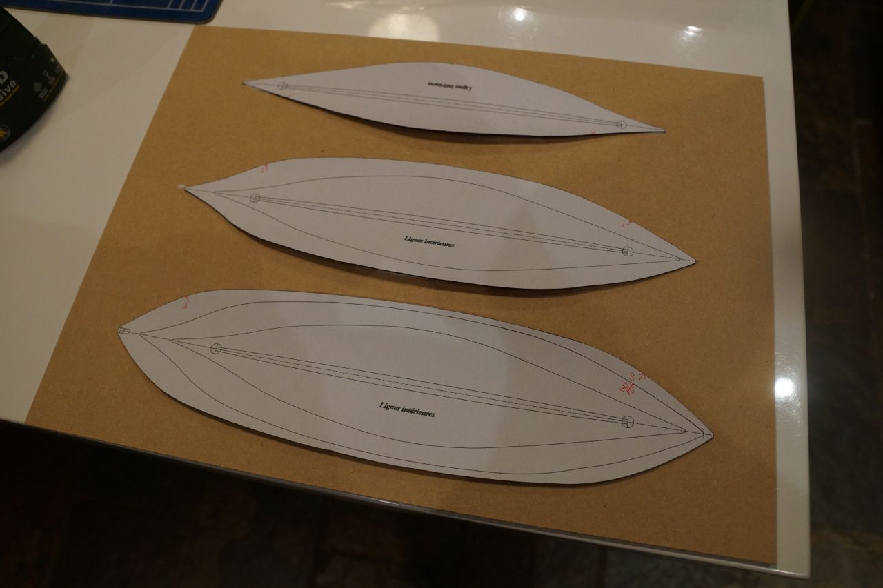
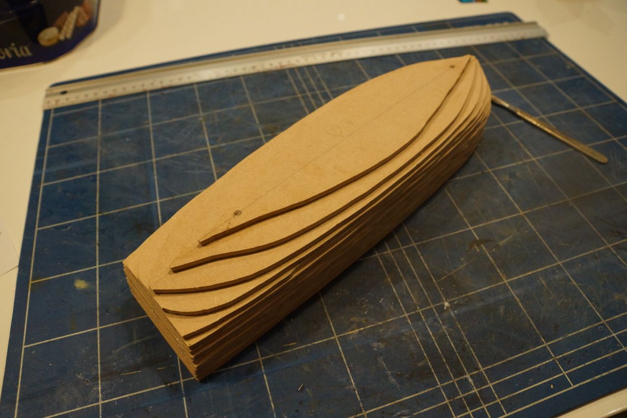
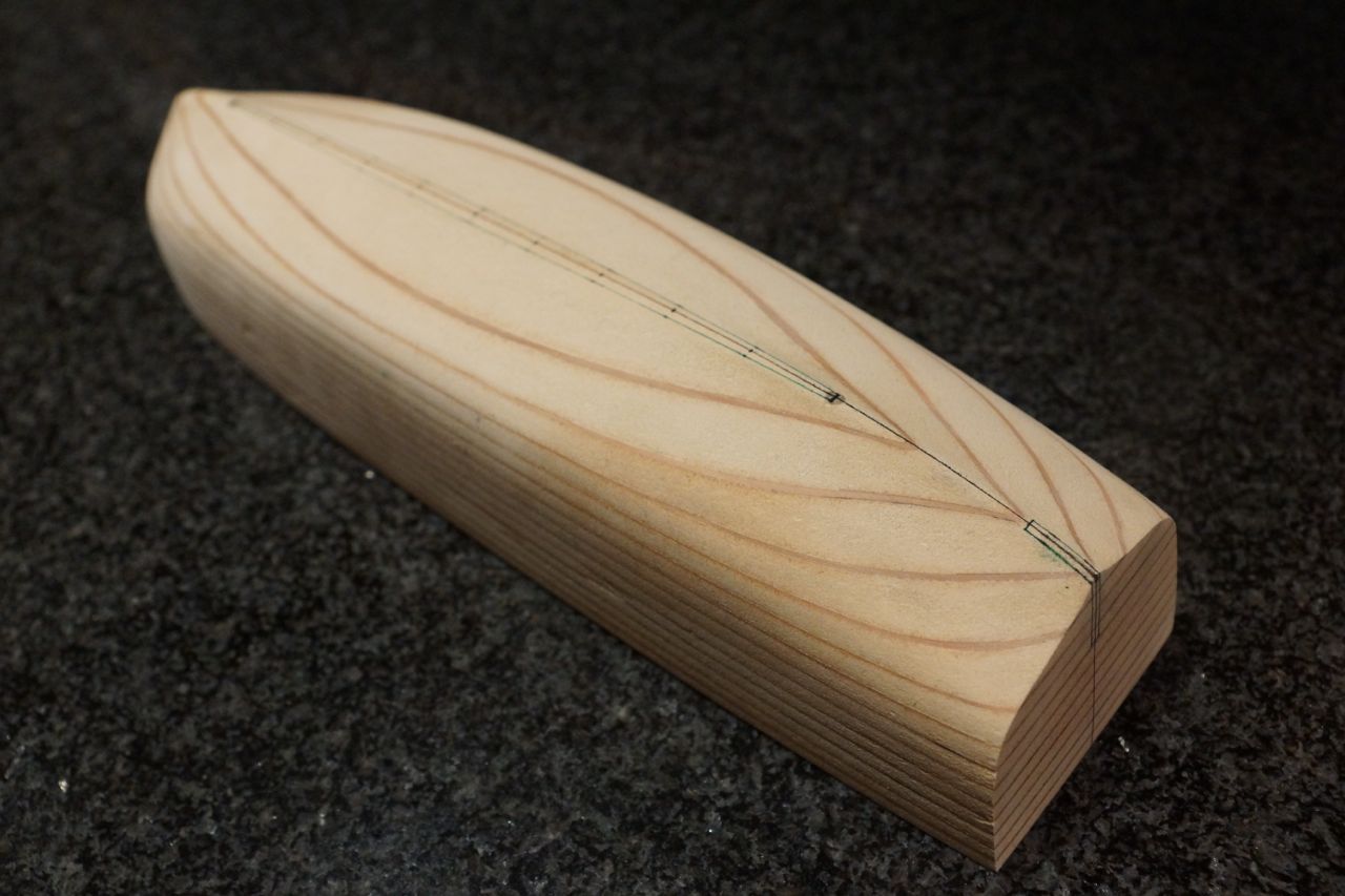
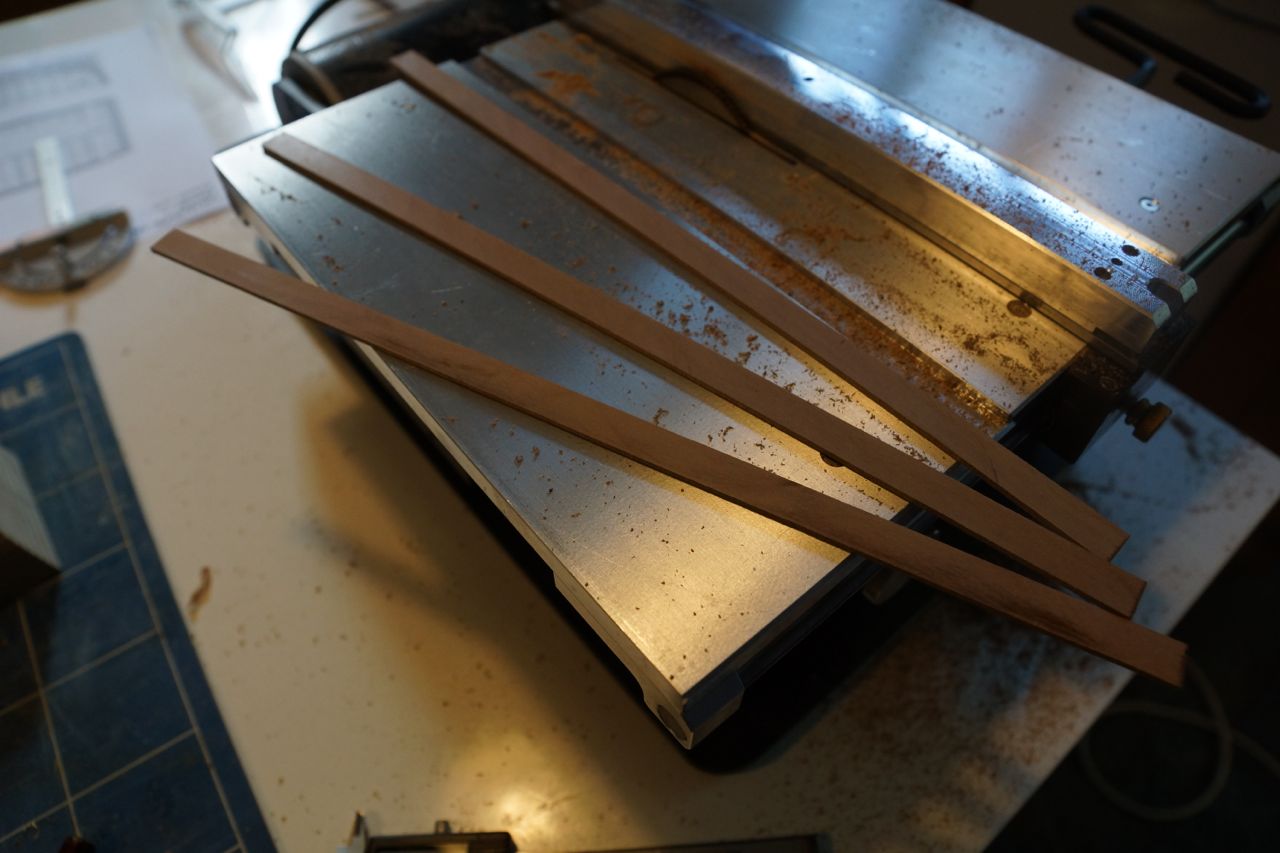
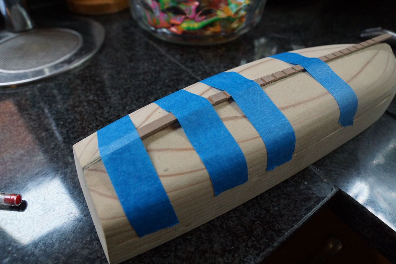
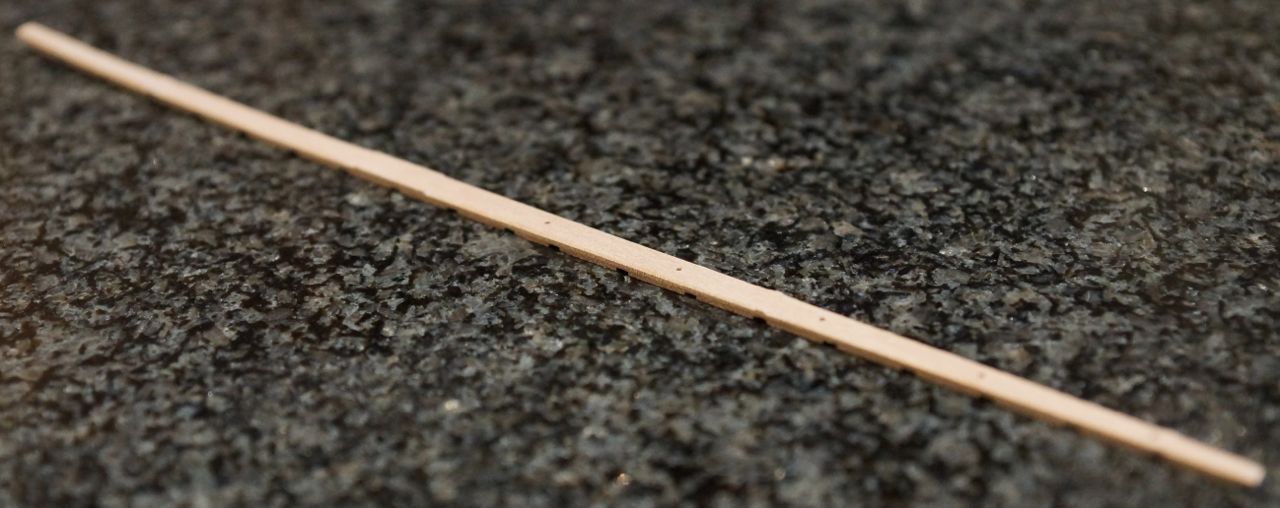
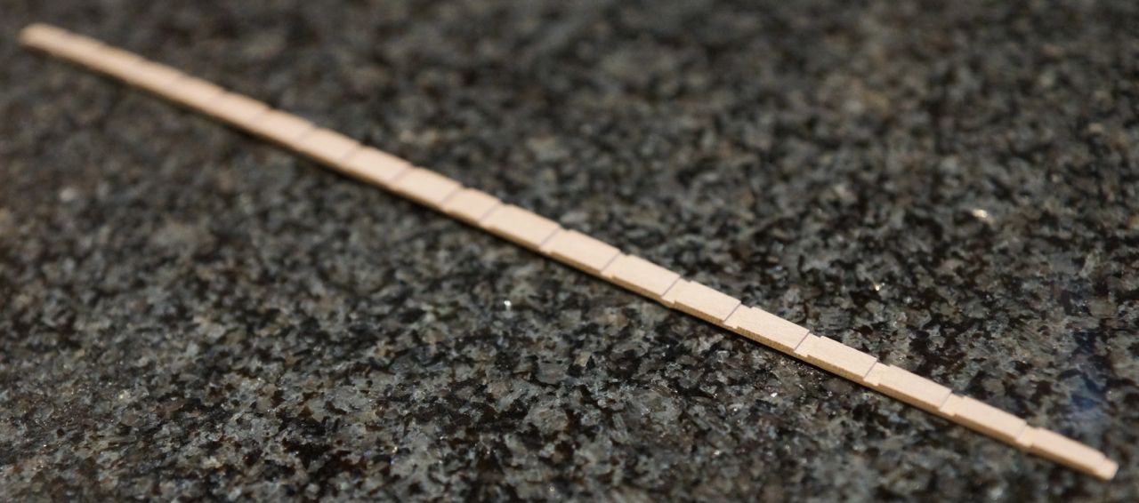
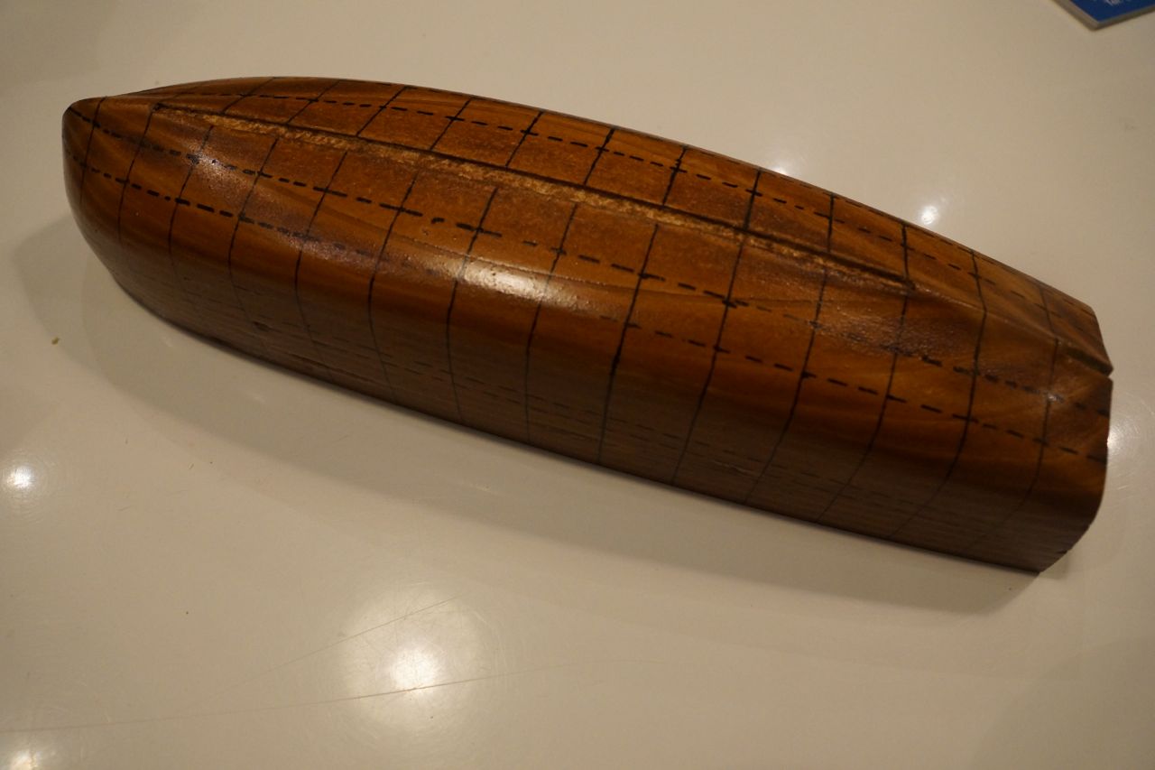
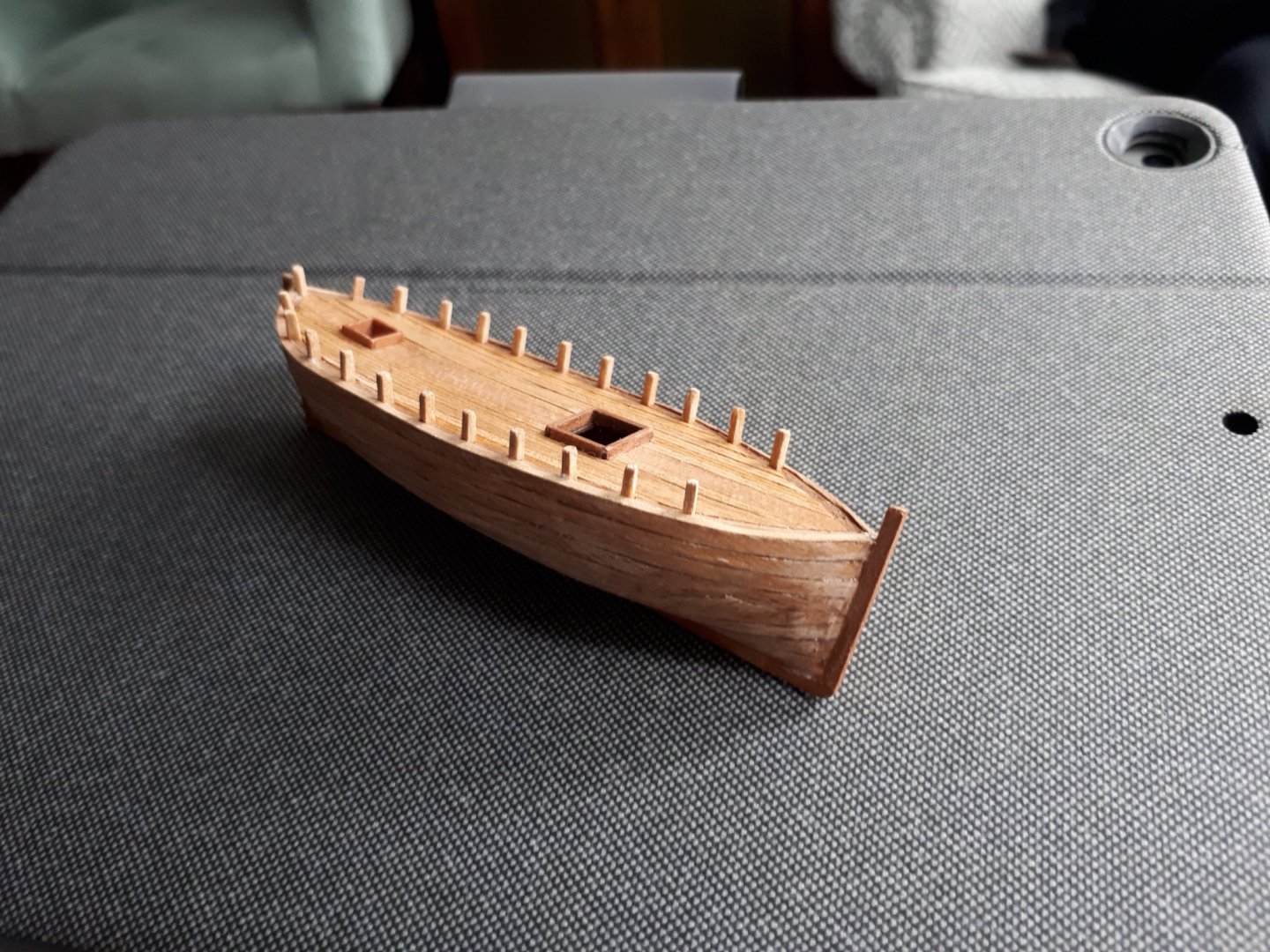
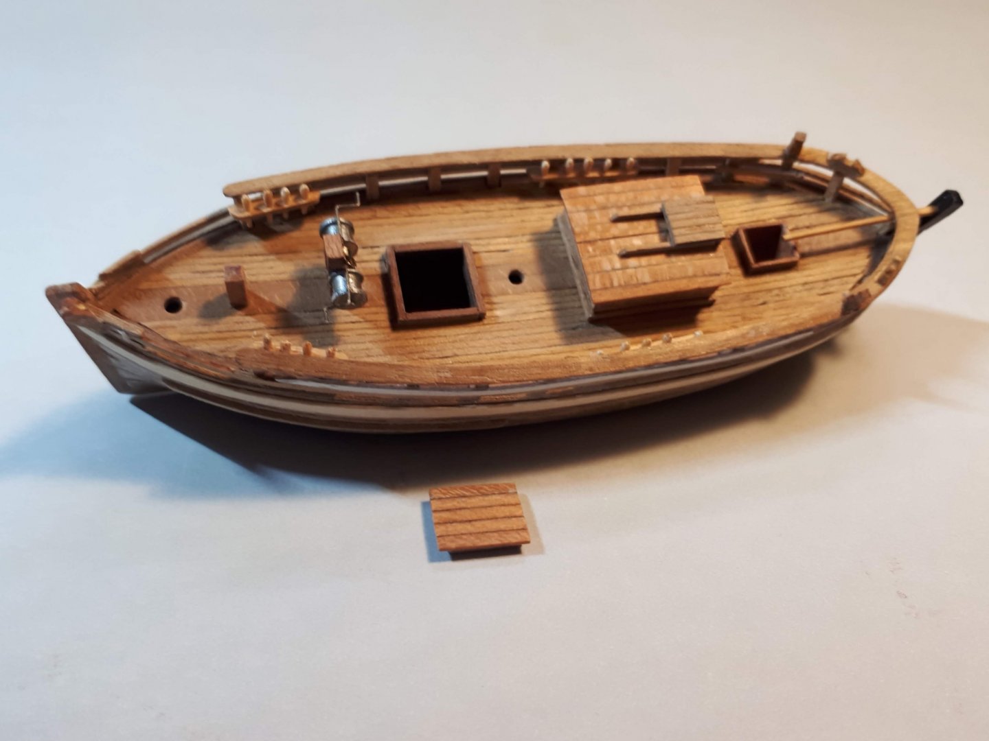
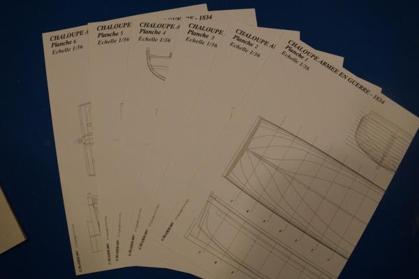
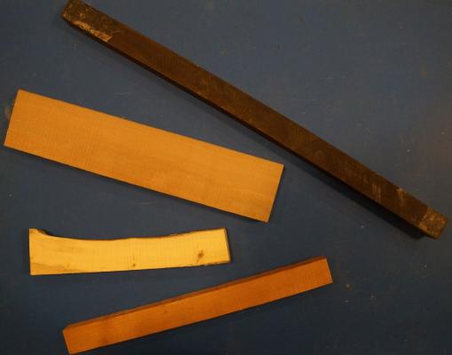
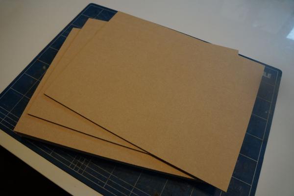
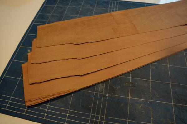
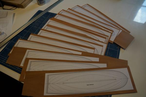
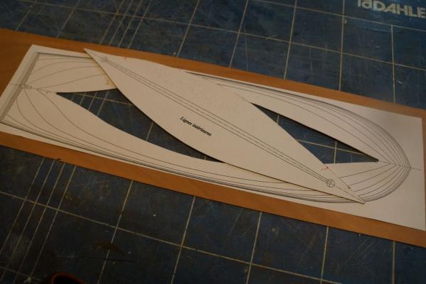
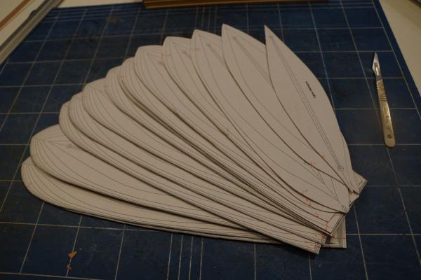
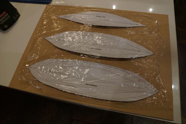
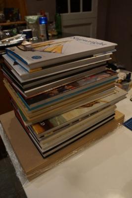
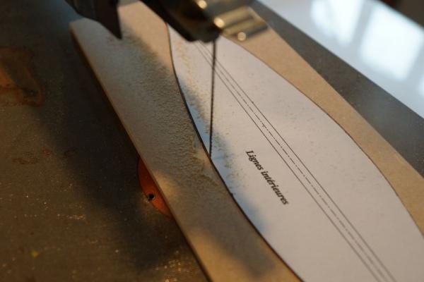
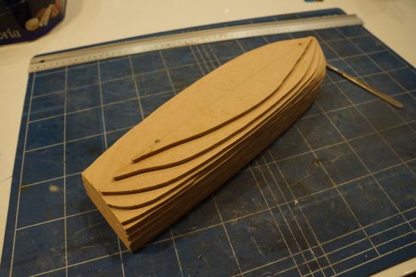
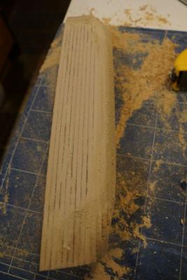
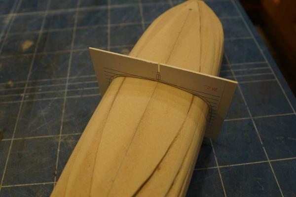
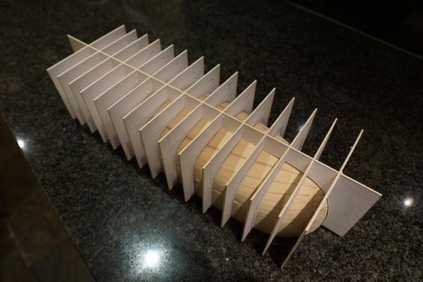
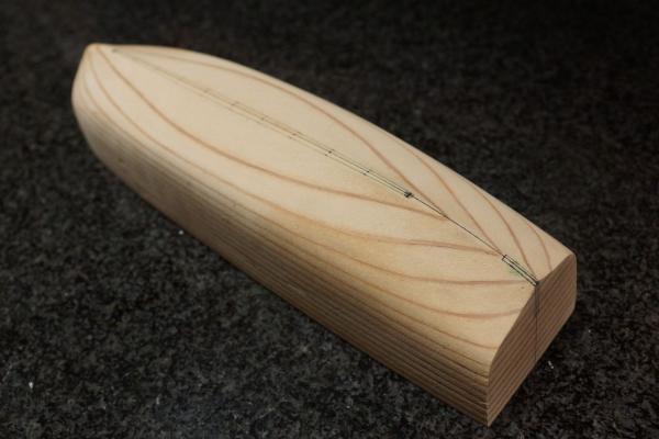
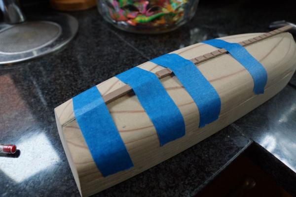
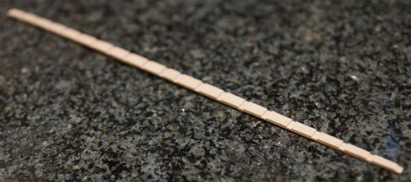
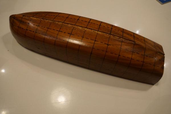
 My next project is the Chaloupe Armee en Guerre or Longboat Armed for War. This will be a scratch-built model at a scale of 1:36, from the plans available here: http://www.ancre.fr/vaisso25.htm. I ordered my copy of the monograph and plans direct from ANCRE and they came speedily and at a very reasonable rate of postage. This is the first publication from ANCRE that I have seen, and I must say I'm impressed. The six sheets of plans are drawn beautifully and the accompanying booklet, which describes the boat and the construction process, is very well laid out. There are many illustrations of the construction process, as well as detail photos of a 1:18 version of the same boat. I should note that the original text was in French and has been translated into English by David H Roberts, who has done an excellent job. Whilst finishing my Agamemnon (http://modelshipworld.com/index.php?/topic/1115-hms-agamemnon-by-decoyman-caldercraft/) I have been collecting pieces of wood I thought might be useful when scratch-building. I discovered The Toolpost (http://www.toolpost.co.uk), a treasure trove of woodworking equipment, in Didcot, about 15 minutes drive from where I live. They have a good selection of hardwoods and fruitwoods, mostly in turning blanks, as well as a selection of pieces of boxwood of varying sizes. They were also happy to cut every piece I bought into 1" slices on their bandsaw. This means I can now machine them to exact dimensions on my Byrnes table saw, which is a pleasure to use! I haven't finally decided which woods to use where, but I'm starting with apple for the keelson and ribs and will probably use cherry for the planking. I acquired a box full of odd pieces of wood, including a large amount of ebony, from eBay for a very reasonable sum: I might try turning one of the ebony pieces to make the large bow-mounted cannon. The picture above shows (from the top) ebony, apple, box and cherry. Before I could get going on the good stuff I needed to make a mould, over which the basic hull will be constructed. The instructions say to make this from 5 mm ply, which actually measures nearer to 4.5 mm thick. Unfortunately French plywood is not available in England; here we have 3 mm and 6 mm, which isn't much use. In fact the nearest thing I could find was 4 mm MDF, available on the internet in packets of ten 400 x 300 mm sheets at a reasonable price. This is still not thick enough. The mould is made from layers cut to the shape of the waterlines, if the layers are too thin then the whole boat will end up compressed vertically. My solution was to interleave the MDF with layers of 0.5 mm cherry veneer, which I happened to have around, so that each layer was 4.5 mm in total. There were some benefits to this method: I could glue photocopies of the plans to each piece of veneer and then cut out each layer accurately using a scalpel. Once that was done I coloured the edges with a black permanent marker. This was so when I sanded the mould to its finished profile I knew that when I reached the black I was nearly there. The next step was to glue the veneers to the MDF and remove the photocopies. I left them to dry overnight, interleaved with cling film and weighted down, and then cut each MDF layer out with a fret saw, slightly larger than the veneer stuck to the top. Each layer was drilled on the centreline at stations 5F and 5A and then stacked up and glued in order with dowels in the holes to provide alignment. I used dowels instead of the drill bits because I could sand the dowels along with the MDF. There was a lot of arm-aching sanding to bring the mould to its final form. I used a Surform for quick removal and then coarse sandpaper on a block for accuracy. The end result was pretty accurate but not perfect. To check the profiles while sanding I glued copies of the frame profiles to 1.2 mm card, as well as the keel. I used these to check I was getting the shape right, but I also cut them so they would slot together. Once the mould fitted all the card frames and the keel I was just about done! In the last of the photos above you can see marking out for the recesses to take the keelson and the knee of the stern. To ensure the keelson recess was the right size I made a start on this piece. It's cut from a piece of 2.3 x 6 mm apple on the table saw, which I also used to cut the rebates for the frames. It curves up towards the stern so I soaked it in hot water for a while, then taped it to the mould. Once the keelson had the correct profile I used it to adjust the recess in the mould. The last thing to finish the mould were two coats of varnish and a polish. The purpose of this is to protect the markings showing the frames and the wales and to try to stop the glue sticking the frames to the mould. We'll see how we get on with this in due course. In the meantime the next task is to bend the frames round the mould. More soon! Rob
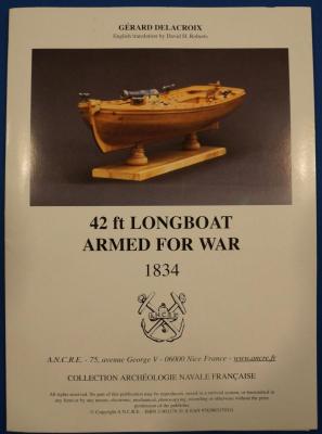


.jpg.a2b9b2e09b5ce45fcc2779b397dfe457.jpg)