Search the Community
Showing results for tags 'falls of clyde'.
Found 1 result
-
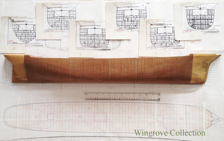
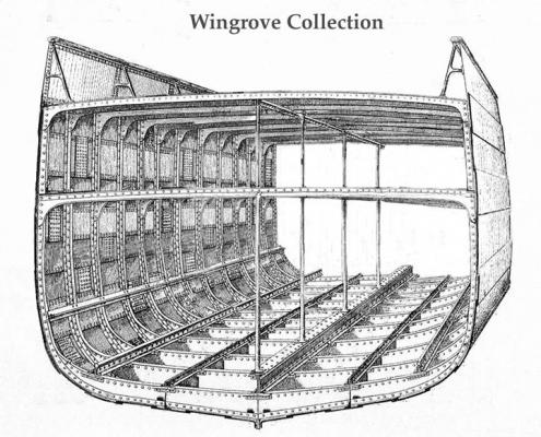
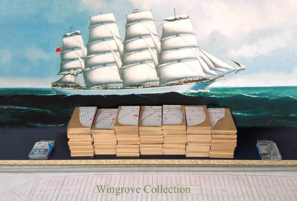
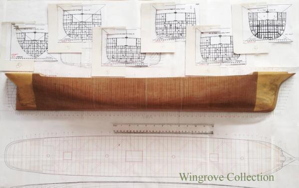
 Substitute brass for iron where ever you see it, as the model is built in brass, but the original is in iron, as also the look of the model will be when finished. To build in iron is very simple, unlike timber, as the materials are already of the correct basic dimensions, thickness and shape, and there are only 3 of them, angle iron, plate, and bulb iron. The complications come in the working of them - with timber it is an adze, saw and boring tool for basics, and each piece is worked on in every dimension. With iron it is a blacksmiths shop and a wealth of heavy machinery to bend and form the 3 basic materials. On my web site at < http://www.wworkshop.net/Falls_of_Clyde/Menu.html > is/will be - the complete ‘Build’ of this model project, but from the viewpoint of the tool making. Here I will create a ‘Build Log’ of the actual building of the model’s - two down and one to go, the last being a fully rigged waterline model of the FofC, still yet to be made. I will aim to do this with 4 photos a month and a brief description of what is going on. At the end of the month I will answer any questions and move to the next stage. In this way I would hope that ‘we’ can cover more fully what you as model makers wish to know to follow in these footsteps, with out repeating what has gone before on my web site. The subject - The Falls of Clyde, is a 4 masted sailing ship of 1807 tons gross, built by Russells & Co., Port Glasgow in 1878. After 324 voyages under sail, with a first class reputation as a fast and friendly ship, (later rigged as a barque), now lying forlorn and neglected in Honolulu awaiting a fate, that has already being spoken of, as being sunk as a divers wreck, if money is not very soon forthcoming to get her into dry-dock as a start to a new full restoration. The other option that I have been promoting for the last 10 years, is to get her back on the Clyde in Scotland, where the Clyde Maritime Trust have the crew and knowhow to bring the old girl back to life, to spend her days along side the Glenlee, a 3 masted barque of the same period, that they have just recently restored in all her glory. Anyone wishing to contribute to this please drop a note to Frank Brown <Frank.Brown@thetallship.com> Plans - There are no fully detailed plans of the ship that I know of being available. There are a couple of people working on producing a set but as yet there is still much work to be done. There is/or was, available a copy of the original side view of the hull, together with a centre cross section, plus a several smaller detailed drawings of the loading ports, 4 in the stem and two others on each side towards the midships and some other odds and ends. These were copies from the original Russell & Co. 1878 ships plans, I obtained mine 30 years ago, from I cannot remember where. These I digitised and expanded adding data from the actual ship, that I have visited 4 time, the first in 1970, shortly after her last full restoration, the last in 2005, when I created eruptions with those responsible who had let her get to the sorry state that I found her in. However some of my developed cross sections seems to have been some way out as to the hull shape, for just as I was about to start the half model I was provided with copy of cross section of the hull made at the time she was converted into a tanker, in 1907. It was these that I then used for my final shape. For those wishing to take this further, unless you wish to undertake a lot of research or await the coming of a set of plane, how-long-is-a-piece-of-string, then better to take a look at something like the Balclutha, still with us in San Francisco, in excellent condition, with a full - very full, set of plans on line at: < https://commons.wikimedia.org/wiki/File:Balclutha_Deck_Plans-_Poop_Deck,_Forecastle_Deck,_Main_Deck,_Main_Deck_Structural,_Tween_Deck,_Tween_Deck_Structural_-_Ship_BALCLUTHA,_2905_Hyde_Street_Pier,_HAER_CAL,38-SANFRA,200-_(sheet_4_of_69).png#filehistory > I will have more to say about this anon - Now to the start and the photos. Fig-01, - Here we see the Falls of Clyde heading for Cape Town on a voyage from Dundee to Rangoon in February 1881 in all of her original glory and depicting the period of my models of her. The painting, an original commission of mine, is by David C. Bell B.A.hon. - for those interested in wooden walls, here you have a friend indeed, an authority on Nelsons ships - check out: < http://www.themarineandwildlifestudio.com/maritime.php > Fig-02, - Showing the inspiration for the iron hull centre section model, the main subject of this Build Log. Fig-03, - The half model - In starting out I had hoped to avoid making a half model, being only interested in recreating the centre 40 frames. My ideas was to work directly from the plans that I had created, taking the lines directly from those. The hull of the FofC are almost those of a late clipper, with not a straight line on them, meaning that no two frames are the same, also meaning that the difference between the size and shape of the centre dozen or so is so minute on a scale to 1/96th that we are down to less than the thickness of a pencil line between them. So to make a half model - To carve a solid model, as is the standard practice, full size and for miniatures, meant having to mark out the individual frames, then transfer this information to the ‘loft floor’ from which the frames could then be formed to match - but then we are back to the thickness of a pencil line and I do not trust my judgement to that fineness. The frames are 2 feet apart - scale size .25” - so I figured that by making the half model with plates of 1/4 thick MDF board, I would have one plate for each frame. By bolting together as many as I could, with a block of wood at each end, and carving this to exactly match the hull drawings, using card templates to double check, would solve all of the problems. Why not use the card templates for the frame shapes? - because one only needs a half dozen side templates, together with several longitudinal ones to create a full half model - it is joining up dots to a free flowing line from a given point to a given point. When looked at, at 1/4” intervals, they look like straight lines, but as a set formed together, they each have a flow. The MDF plates were cut square and accurately and provided with a datum point common to them all. Each plate was then given a copy of it’s cross section from the original drawings with as much information on it as possible and matched to the datum point. These were then placed in a simple drill jig and provided with two hole, with a centre section plates being provided with 3, all to take long threaded rods. The position, as with the width of the two end blocks being determined by the size of the washers & nuts necessary to hold them all together. As the frame plates reduce in size fore and aft, so the space available to hide a nut and washer inside becomes less and less. Each plate was then jig sawed to shape leaving about an 1/8th inch clear from the paper pattern, to take care of any inaccuracy in the drawings. The final shape being determined by a pleasing line of sight, as was the practice full size. This assembly was then wood screwed to a back board of 3/4” melamine covered chip board, cut out to match the side profile of the hull. The whole then carved to shape, with chisels, gouges, sanding discs, files, with fine paper to finish. Fig-04 The basic half model, also showing in the background 6 of the hull cross section drawings, drafted at the time the FofC was converted into a bulk oil tanker in 1907. These were used to correct my original drawings. Note that there are three white lines showing between the plates, that are in fact very thin plates of aluminium. They indicate the extent of my 40 frames, together with the centre frames - more about this as we proceed.
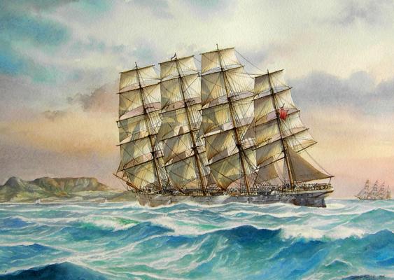
- 281 replies
-
- 19
-

-
- tanker
- sailingship
- (and 1 more)