Search the Community
Showing results for tags 'lateen'.
Found 8 results
-
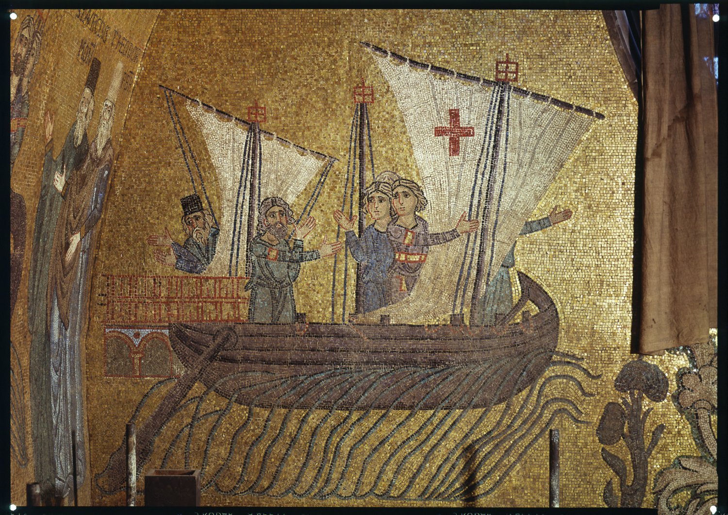
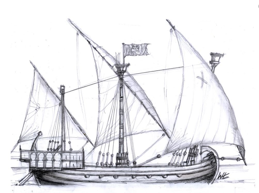
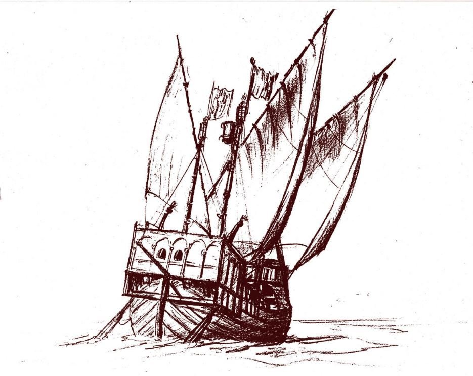
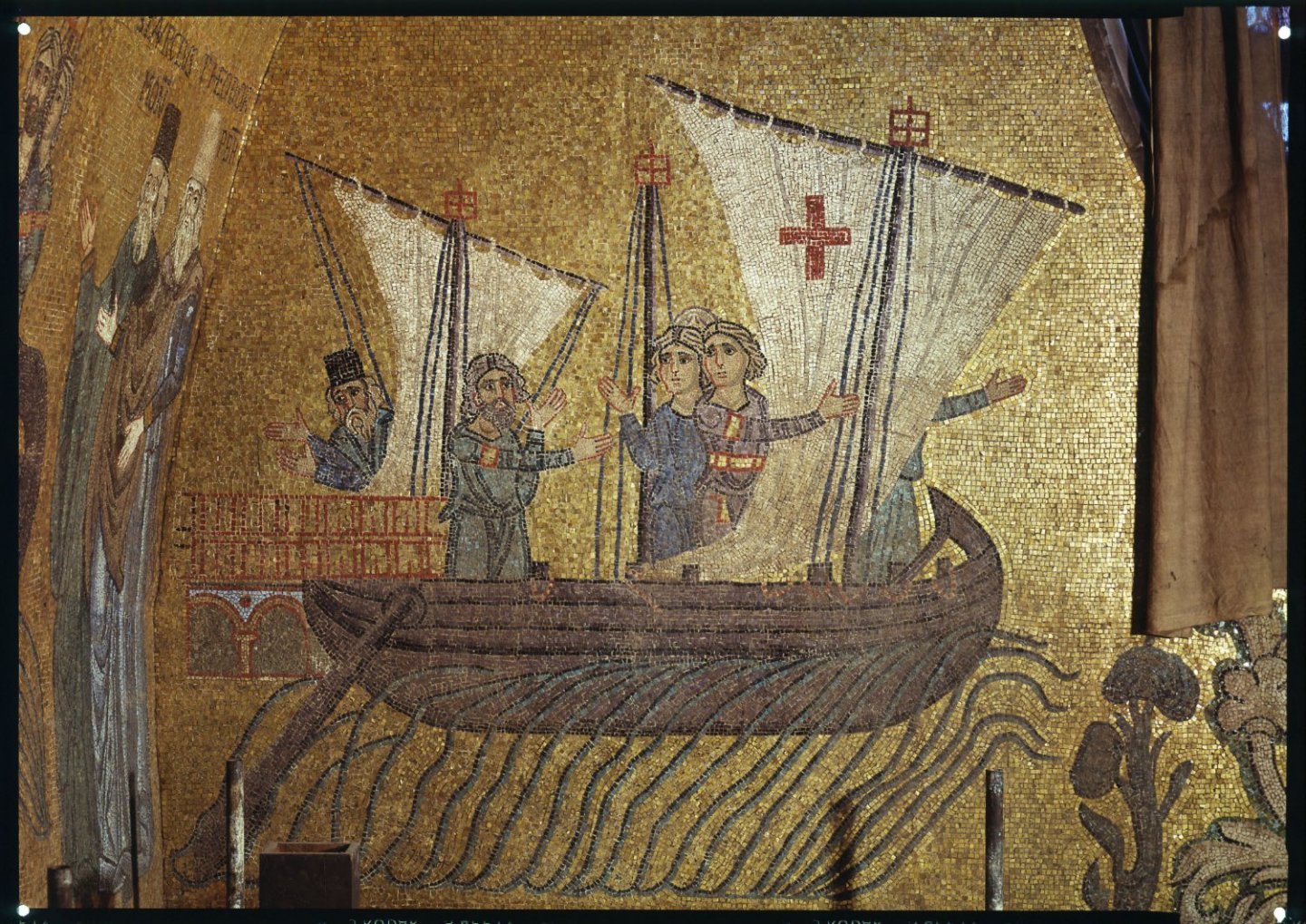
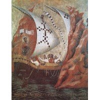
 In the church of San Marco (Saint Mark's) in Venice is a series of mosaics celebrating the so-called "translation" of the body of Saint Mark from Alexandria to Venice, where he became the city's Patron Saint. "According to legend, Saint Mark’s body was taken from Alexandria, Egypt, in 828. Two Venetian merchants travelling in Alexandria, obtained the relics of Saint Mark from Priests at the church of Saint Mark, where the saint’s body was interred. The Priests feared Saint Mark’s relics might be damaged or destroyed by the Saracens during the persecution of the Catholic community in Alexandria. Promising to safeguard the Saint’s relics, the merchants convinced the Priests to allow them to return to Venice with the body of Saint Mark. The body of Saint Mark was taken out of the sarcophagus and unwrapped from its silk shroud, the relic being substituted by another and less eminent Saint. It was then placed in a chest and taken on board the Venetian ship, the merchants first ensuring, that the Saint’s remains were covered by a layer of pork and cabbage. When the Muslim officials asked to inspect the chest, they cried out ‘Kanzir, kanzir’ (Oh horror) at the sight and smell of the pork. . . . Thus the Evangelist was safely conveyed to Venice but not before a number of miracles eased his passage across the Mediterranean.” There are five mosaic panels showing the ship itself at various stages of the voyage. They are all very much the same - three masted, lateen rigged, with two side-rudders - but with minor variations in the shape of the aftercastle, the stempost, the line of the gunwale etc. Some of these variations don't make a lot of sense and I am going to have to reconcile them and come up with a version that I'm happy with. This is a rather difficult ship to get a good concept of, but I was inspired by a couple of sketches on a Facebook forum by Wagdemar Lookomsky (I hope he doesn't mind me posting them here) which finally suggested a configuration for this ship that made sense. I'll be using these as a basis for my own reconstruction, but I won't be copying them exactly. I will be basing the hull shape mainly on that of the 14th century Contarina ship which Woodrat has already used for his 14th century Venetian Round Ship (see https://modelshipworld.com/topic/17991-venetian-round-ship-13th-century-by-woodrat-132-scale-fully-framed-completed/ ) and I will be shamelessly copying much of his technique in building my own (though at a smaller scale). However, this is at the research stage at the moment. First I want to get a lot more done on my Great Harry restoration, which as languished while I built my nef. But this is a bit of a heads-up for those who are interested. Steven
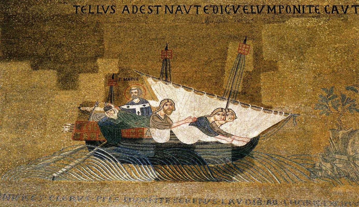
- 381 replies
-
- 16
-

-
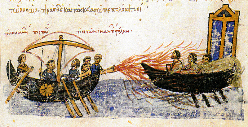
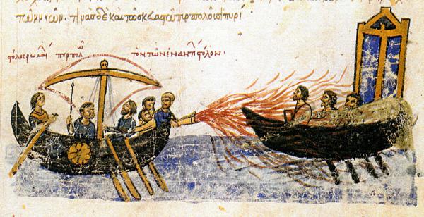
This is the very beginnings of a build log. Until I have finished renovating the house, there’s no chance of actually doing any building – no time, and no space available. But in my free moments I’ve been researching and drawing up plans for a Byzantine dromon of the 10th-11th century. The name dromon (Greek = “runner”) was originally applied to a class of fast Roman galleys with a single bank of oars developed around the 6th century AD. Over the centuries, as the Roman Empire shifted its emphasis to the East and gained a new capital in Constantinople (modern Istanbul) and evolved into what we now know as Byzantium, the dromon changed as well, until by the 10th century AD it was a very different vessel with two banks of oars, lateen sails and armed with a devastating weapon, pyr thalassion – Greek fire. Greek fire is generally accepted as having been made of naphtha, a naturally occurring substance similar to petroleum. Contemporary descriptions led Prof. John Haldon to work out theoretical design using only technology known at the time, and then put it into practice, with spectacular results (see https://books.google.com.au/books?id=q0hMf5vu7kgC&pg=PA289&lpg=PA289&dq=%22Greek+fire%22+revisited:+recent+and+current+research%22&source=bl&ots=Kwp5Xa3U62&sig=tR81SBsNfAc_uDLyuXDxe9uPWKA&hl=en&sa=X&ei=bjAzVc61C8TNmwWvv4HICw&ved=0CCYQ6AEwAw#v=onepage&q=%22Greek%20fire%22%20revisited%3A%20recent%20and%20current%20research%22&f=false - page 292 onward). Greek fire was used effectively in a considerable number of battles, destroying threatening enemy fleets. I was reported to have burnt on the surface of the water (and in the reconstruction that’s just what it does!). The definitive source on the dromon is the excellent, thorough and painstakingly researched book Age of the Dromon (http://www.brill.com/age-dromon-0) by Professor John Pryor and Elizabeth M. Jeffreys, which draws together all the clues as to the nature of the vessel, from its early development to its apogee in the 10th and 11th century. The available information is rare, widely scattered and often difficult to interpret. At the time it was written no remains of any Byzantine war-galley had ever been discovered, let alone a dromon, contemporary descriptions were vague and patchy (and in the case of at least one writer of the time, often wrong). Contemporary illustrations are equally unsatisfying and the conclusions and resulting reconstruction reached are a considerable achievement. There have been a lot of theoretical reconstructions of dromons over the years, many of which can be seen if you do a google image search for “dromon”. Some of them are quite ludicrously wrong – often clumsy and far too heavy for a vessel propelled by muscle power. Prof Pryor’s reconstruction is the best and most believable I have seen, and is based firmly on the available evidence. It would also make a fast and effective warship, which most of the others wouldn’t. The picture that emerges is of a long narrow vessel with 100 oars arranged in two banks of 25 on each side. Instead of an outrigger, the sides were flared outwards at the gunwales to allow a good angle of attack for the upper oars. The vessel was fully decked and had two lateen rigged masts and dual side rudders. There was a fortified forecastle, below which was the siphon for Greek Fire. On larger dromons each gunwale was built up amidships and fortified with a wooden ‘castle’. In the centuries between ancient and mediaeval galleys, shipbuilding techniques had changed from frameless shell-construction (in which adjoining planks were fastened together by many small wooden tenons fixed into slots in the edges of each strake), to fully framed construction which was far stronger, and unable to be sunk by ramming. Rather than a ram, the late dromon had a long detachable ‘spur’, intended to break the enemy’s oars, to destroy its motive power and manoeuvrability. Instead of sinking opposing vessels, the dromon’s crew used projectile weapons – bows, slings, ballistas and even flung stones to cause casualties on the enemy’s decks until they could pull alongside, grapple and board. The oarsmen of the upper bank doubled as marines, leaving the lower bank to manoeuvre the ship into position. Tests on Olympias, a full-sized reconstruction of an ancient Greek trireme built in the 1980s, determined that such long, thin, light vessels were very subject to the vagaries of the weather and were of very limited stability. It was discovered that it was impossible to row effectively in any sort of sea – waves one metre high were the upper limit – and a galley faced by bad weather had little choice but to run for shelter. Galleys were also poor sailers and could really only sail effectively in a gentle breeze – a heel of more than 10 degrees would swamp the vessel and it would have been all but impossible to sail into the wind. A dromon’s storage ability was minimal and on long trips it would have to put into port on almost a daily basis to replenish stores, (particularly water, which oarsmen need to consume in great amounts to stay effective) A galley’s length is determined by the interscalmium – the distance between the rowing benches. Age of the Dromon estimated the interscalmium to be about 1.0 metre (3’3”). Any closer together and the oarsmen foul each other; any further apart and you’re adding dead weight for the oarsmen to pull along for no reason. A galley with 25 benches in each bank would be about 25 metres long, plus extra for the bow and stern. A dromon was incredibly long for its width – the reconstruction in Age of the Dromon is 31.25 metres (95 feet 4 inches) long and its maximum beam amidships only 4.46 metres (13 feet 7 inches). Just as the book was about to be published in 2006 an amazing discovery was made in Istanbul. During excavations for an underground railway in the Yenikapi district of the city’s southern edge, workmen stumbled upon the Harbour of Theodosius, silted up and buried centuries before. Under the mud were the remains of 37 Byzantine ships dating from the 5th century to the eleventh century AD. Most were merchant vessels, but at least 6 were war galleys – not dromons unfortunately, but galeai – smaller and lighter single banked galleys used for scouting, and from which our word galley comes. The Yenikapi ships confirmed the theoretical dimensions of Age of the Dromon’s reconstruction – of the two galleys which still had their upper works in reasonable condition, the interscalmium of one varied between 0.90 and 0.97 metres, and the other between 0.874 and 1.048 metres, averaging 0.96. The length and beam of these galleys was consistent with the theoretical reconstruction. These vessels were incredibly lightly built – the thickness of the planking varied from 20 to 30mm (3/4”-1 ¼”, almost unbelievable in a vessel of that length, and the frame timbers averaged 60mm (2 ¼ ”) square. The ships were prevented from hogging by stringers inside the hull and heavy wales. Presumably dromons were similarly constructed, with extra stiffness provided by the full deck. I cannot adequately express my gratitude for the wonderful help freely given by Professor John Pryor and also by Dr Cemal Pulak of Texas A&M University. Professor Pryor has been incredibly helpful to a lubber like me and I owe to him almost everything I know of dromons, and certainly my decision that I could actually go ahead and make a model of one with a reasonable certainty of getting it right. He also referred me to his colleague Dr Cemal Pulak, (who took part in the excavation of eight of the Yenikapi ships, including two galleys). Dr Pulak was kind enough to send me a copy of his paper when it was published (it appears in the in the international Journal of Nautical Archaeology 2015 44.1; pages 39-73), as well as a photo of a partial reconstruction of the better preserved of the two galleys he excavated, built at a scale of 1:10. My model will follow Professor Pryor’s reconstruction as closely as possible, with a few modifications based on the Yenikapi finds and on some discoveries of my own when drawing up the model to scale. However, before constructing the full model, I plan to make a midships section at 1:20, with three sets of working oarsmen, as Professor Pryor pointed out that though theoretically the two banks of oars of his reconstructed dromon should not foul each other (Olympias had a lot of trouble with broken oars from fouling between oars of different banks), they have not been tested in the real world. I've attached a PDF of the plans in their current state of development. It should be very interesting. Steven dromon.dwg Model (1).pdf
-
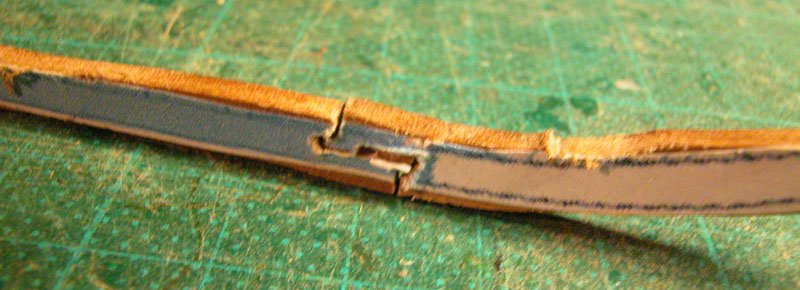
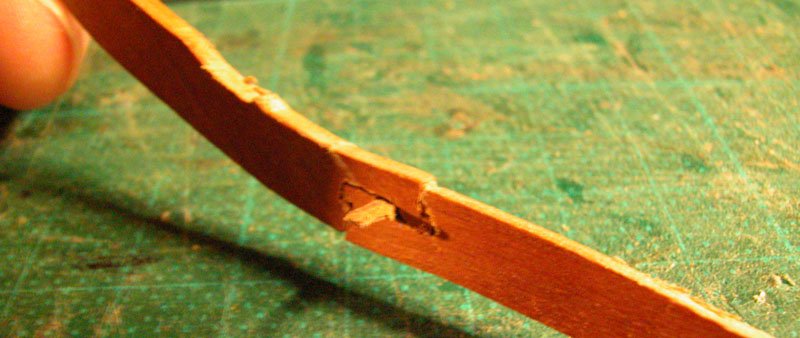
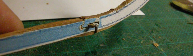
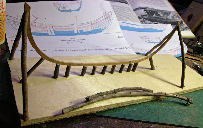
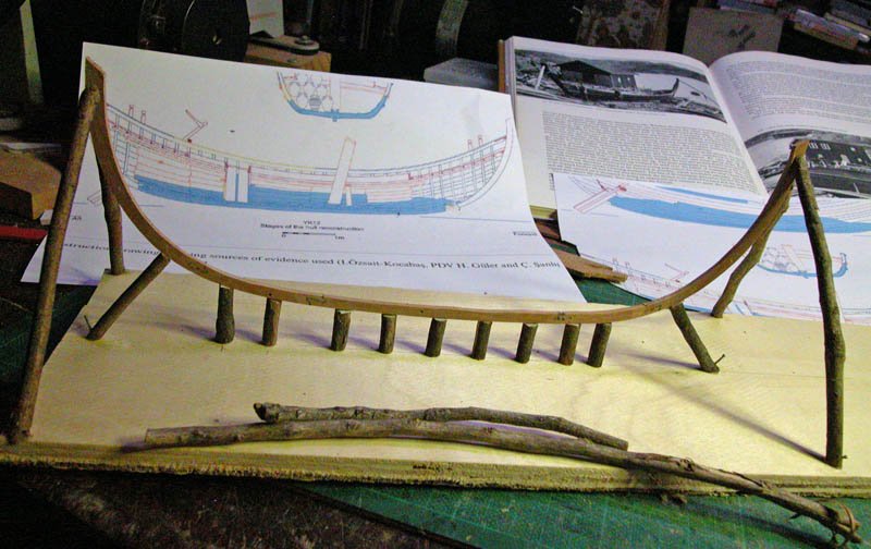
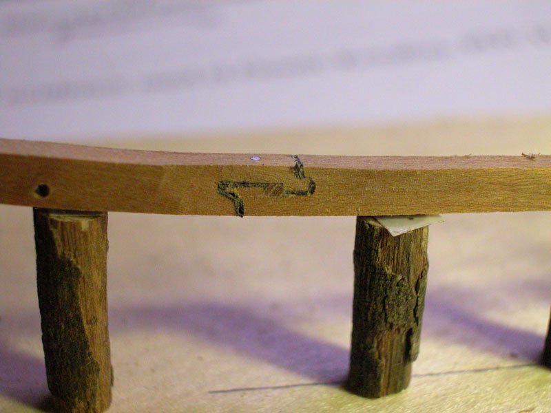
 Having largely finished my build of the 13th century Round ship, I am going back in time to the 9th century. At this time a transition was in play in the Mediterranean away from the shell construction using edge joined planks with pegged mortices to what would become the skeleton type of construction using full active frames. The vessel I wish to construct was positioned in between these techniques in that it had a mixture of shell and skeleton construction used in its construction. In addition , instead of using mortice and tenon technique to edge join the planks, it used an edge dowelling technique. I will utilise the description and reconstruction published by the author: Işıl Özsait-Kocabaş Istanbul University, Department of Conservation of Marine Archaeological Objects, Ordu Cad. Laleli, Fatih, ˙Istanbul, Turkey The International Journal of Nautical Archaeology (2018) 47.2: 357–390 Copyright for images from this publication resides with Istanbul University Yenikapı Shipwrecks Project, I will withold these. I hope to be able to demonstrate the techniques used by the original builder. The dimensions of the vessel are length overall (LOA) 9.24m, beam of 2.64m, and depth of 1.10m. The length-to-beam ratio of the vessel is 3.5:1. The wreck was found in 2007 at the site of the byzantine Theodosian harbour, one of the greatest treasure-troves of nautical archaeology yet discovered. The wreck of YP12 has good preservation of keel, framing and planking sufficient to do a viable reconstruction. The keel is rockered, that is slightly curved, and made from three pieces joined by keyhole scarfs The stempost and sternpost did not survive and have been reconstructed. I have temporarily installed the spine of the vessels on posts as I believe the original builder would have done. This may end up becoming the stand of the model. Cheers Dick
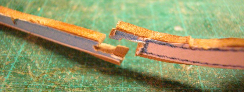
- 116 replies
-
- 13
-
-
Having completed the venetian carrack or cocha, I now plan to reconstruct a merchant vessel that predated it and lasted into the 15th century. I have based the reconstruction on the measurements given for a nave latina in Michael of Rhodes 15th century manuscript. This has been combined with the framing details of the Contarina 1 wreck excavated and fully measured at the end of the nineteenth century. The details of superstructure and planking will be loosely based on the vessel shown in the Translatio of St Mark painted by Veneziano. Woodrat
- 263 replies
-
- 9
-
-
- nave tonda
- round ship
- (and 2 more)
-
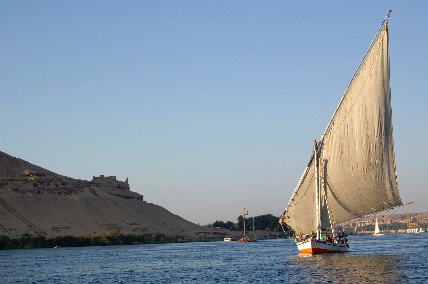
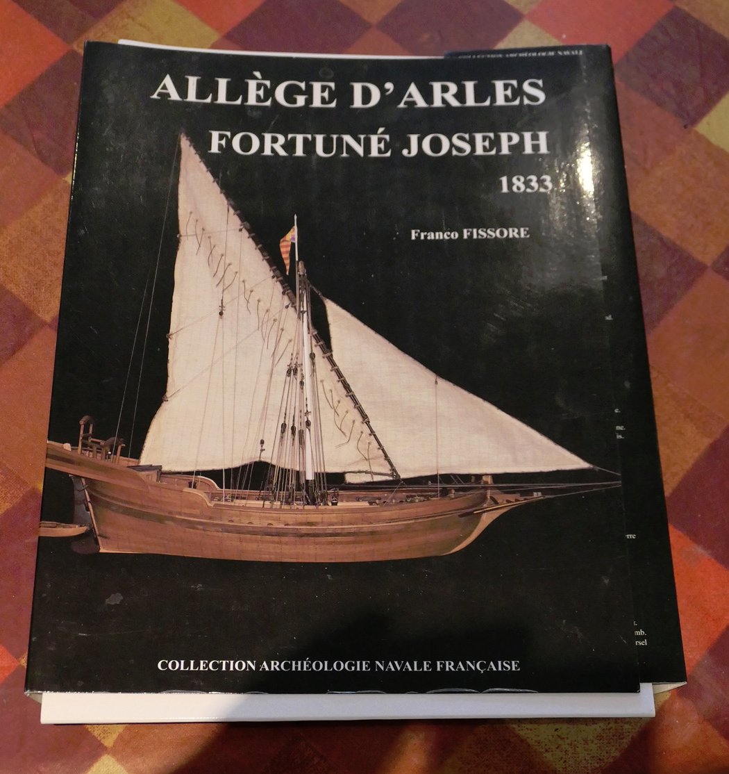
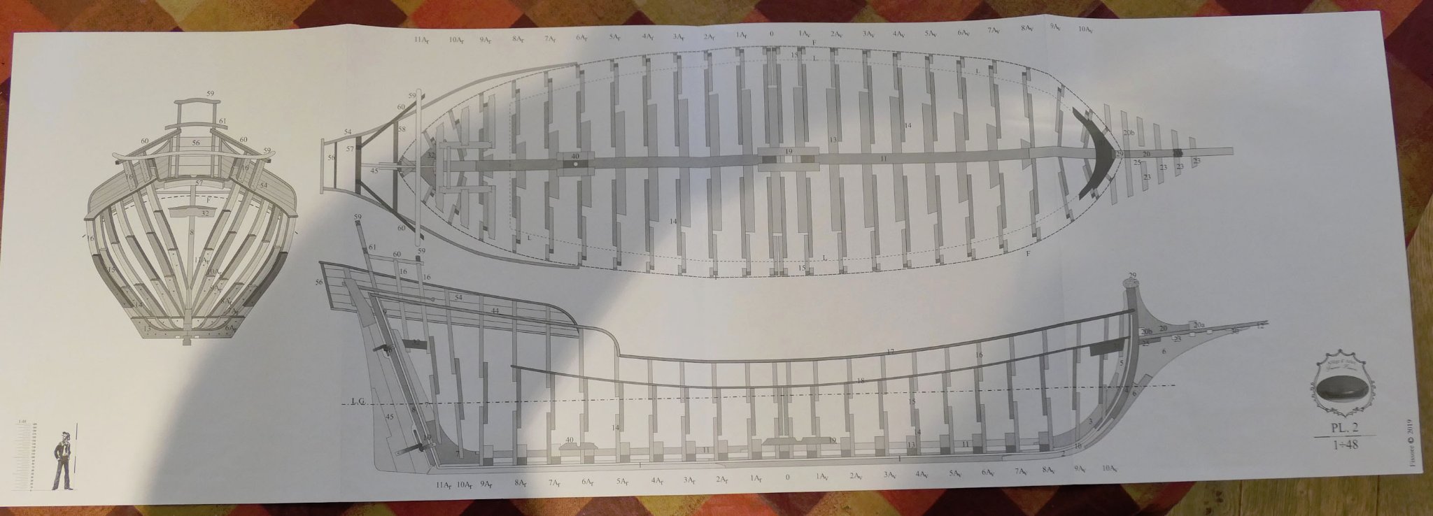
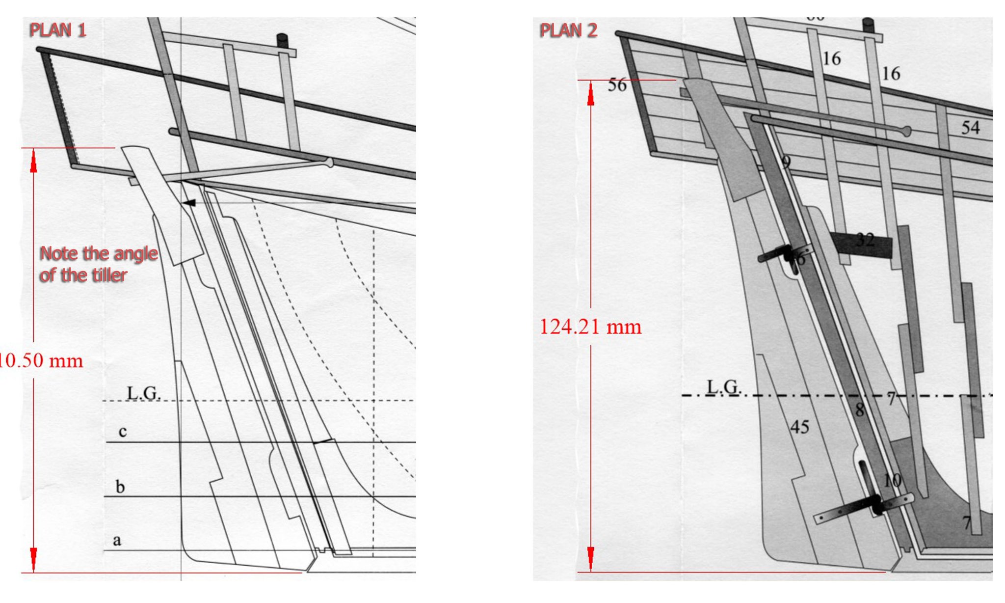
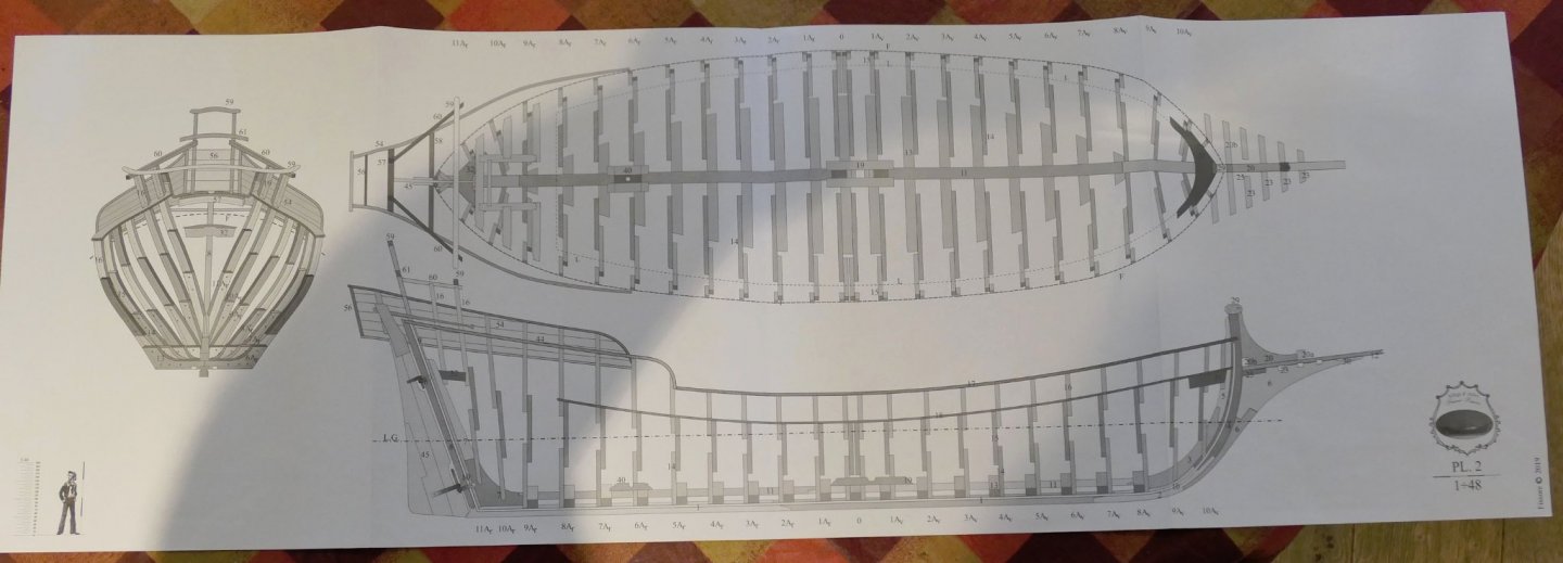
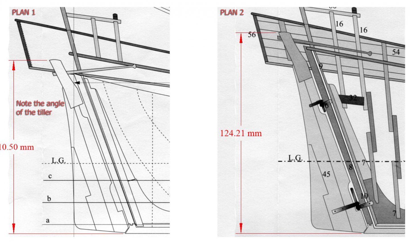
 INTRODUCTION & RATIONALE I was given the Ancre monograph of the Fortuné Joseph, an Allège d’Arles (the English translation), and, as I was wondering what next to build, this looked like a good possibility. There were lots of variation to these allèges, or lighters, in the 19th Century, but all had in common their lateen rig and general shape. Ever since being taken on an Arab felucca on the Nile (the one in my picture below), I have been intrigued by the lateen rig. I haven’t been able to find any plans or construction details of a Nile felucca (if anyone knows of any, please do advise me), but this Mediterranean version seemed near enough and I liked the lines – so I decided to jump in and try my hand at a build. I have treated my previous builds as a kind of enjoyable apprenticeship, learning the different ways of approaching builds, experimenting with wood and card, understanding the various types of tool that can be used, and getting to grips with plans and CAD. In particular, I have tried to figure out what aspect of model-making interested me most: the type of model, the historical research, the level of detail, the level of skill, the level of accuracy, the general image, the balance between thinking and practical building, the presentation of the model when finished. My first realisation was two-fold: I am far more interested in working or merchant craft than in warships, and completion of the model holds very little interest for me. I simply don’t know what to do with the completed models, other than give them away. The second realisation was that, partly because of my lack of interest in the completed model, and partly because I have nowhere to place them when finished, I would like to explore the creation of small-scale models. I had seen Javier Baron’s 1:200 build of the Allège, and thought that that scale would be an ultimate aim for me, but for the moment I thought I’d focus on a similarly large scale. After seeing kondzik’s build of the card kit of the Allège d’Arles published by WAK, I bought the card kit and built it just as far as the completion of the hull and its planking. This kit seems to be very similar to the allège in the Ancre monograph (although there are lots of differences – such as the dimensions of the quarterdeck) so this would give me not only a good idea of the overall lines and problems that might have to be overcome, but also an insight into the use of card to scratch build a hull. I had had the idea of building hull bulwarks just with card and finishing the rest of a model with wood, as I’d seen someone do that with a Shipyard card kit of the Alert. At first I wasn’t going to make this into a log for a model forum since it really was an experiment just to explore the possibilities as I will explain further on. However, I decided in the end that there may be enough interest in reflections on the Ancre publication to justify a log of my build that is definitely full of mistakes, and a rather ramshackle construction and finish. For these I apologise. The build of the card kit also gave me a little experience with using filler on a card model to provide a good surface for the planking, as so many card modellers have said that without filler it is quite difficult to avoid depressions in the curve of the hull. I followed Ab Hoving’s suggestion of a standard water-based filler. THE PLANS Unfortunately, the monograph and plans drawn by F. Fissore of the allège (as others have noted with builds of the Gemma and S.Caterina) do not match the excellence and comprehensive nature of the monographs from other authors published by Ancre such as Jean Boudriot and Gérard Delacroix. Thus this monograph has a very different approach: the usual detailed analysis of the plans in the monograph is instead merely a list of the parts shown in each plan, there are no scantlings provided for any parts or rigging (we are not even given the dimensions of the keel), and the guide to the building of the boat is almost entirely in photographs of the author’s build (most of which are very small, of poor resolution and thus hard to demonstrate detail). This approach might not be so worrisome to those used to working from plans. It should also be pointed out that the section on rigging is good, especially given the fact that each aspect of the rigging is given its own illustration in the manner of Lennarth Petersson, and this will be discussed later. Another big plus is that the plans are laid out on long pages whose height is that of an A4 page in portrait mode – making it easy to photocopy and then stitch the pages together. [The dimensions of this photo have been modified to avoid replication.] However these positive aspects are offset by lots of errors in both monograph and plans which need correction. My first realisation of problems with the plans came when I compared Plan 1 with Plan 2. They showed the rudder and tiller entirely differently as follows: In this instance, Ancre immediately responded to my request for clarification and they sent me a pdf of a revised Plan 1 which corrected this anomaly – Plan 2 showing the correct dimensions. The anomaly made me study the monograph more intensely in case there were further problems which I needed to bring to the attention of Ancre. I soon found lots. There are four main types of problem: 1. The plans are inconsistent with the method of building shown in the photos of the monograph. (a) There are many details in the photos of the actual build which are not shown in the plans. This led to my having to undo some of the work I had done when I finally spotted the often important detail. One of the many examples is that there are inconsistencies about the number of beams running under the bowsprit fore timbers. (b) Less importantly, the plans show the frame top timbers extending to the top rails throughout, but the pictures of the build showing the method of construction show the frames ending beneath the lower waterway with the timberheads being constructed separately and fitted into square holes in the waterways and rails. The confusion is worsened by the fact that the plans of the frames themselves do not show the position of the ends of the top timbers at all accurately. Of course, once this is understood, the experienced modeller will be able to adapt their thinking and modify the plans accordingly, but it is at first very confusing when comparing photographs with the plans. 2. The second type of problem is that the plans of the frames are incorrectly drawn, especially in Plan 4 of the frames which shows the floors of each frame extending only to the top of the keel rather than to the top edge of the rabbet. Once this has been spotted by the modeller who has been careful to examine the measurements this again will not be a problem. The base of the floors has simply to be extended by a few millimetres (depending on the scale that will be used). 3. The third type of problem is that of inconsistency between the plans. Thus in some the waterways are shown correctly, and in others they are simply not there. There are many other similar discrepancies. 4. A fourth, more irritating problem, is that the numbers on several of the plans do not match the text of the monograph, nor are they consistent on different pages of the monograph. On some of the plans the numbers are duplicated, with different parts having the same number, on some the parts are given the incorrect names (e.g. a rudder blade is given the same number as a top rail; the keel and the sternpost are both referred to as the sternpost); and some parts are given no reference at all. Some of these difficulties may possibly be due to the very poor translation into English (some pages are not translated at all from French, which is itself a translation of the original Italian) but obviously the experienced modeller will be able to manage once aware of the difficulties. All of these are a great pity as excellent models of the Gemma and S.Caterina (both plans by Fissore) have been built (although they do mention but do not detail the difficulties they faced with the plans), and the ships themselves have great attraction. M.Fissore himself shows photos of the builds of his various models including his own of the allège (at Archeologia e Modellismo d'Arsenal) and it is well worth the visit as the photos there are far, far clearer than in the book). I have written a fairly detailed list of these various problems and submitted them to Ancre for consideration by M. Fissore, so it may be that future editions of these plans and monograph will be made more amenable for a wider range of modellers. A very similar boat, La Diligente, which was a lateen Navy messenger boat of the 1750s, whose monograph is published by Ancre and written by Gérard Delacroix & Hubert Berti, has the same level of complexity but is not only incredibly detailed and thorough together with complete scantlings: it also provides a set of plans that will allow the less experienced modeller to make it POB rather than POF. In the interim, as long as one is aware of the problems with plans and monograph, the experienced modeller will be able to use the correct body, sheer and breadth plans on a corrected Plan 1 as the basis for their model. I'll be adding stages of the build over the next few weeks, so I hope it will be of interest. As usual, don't hold your breath! Tony
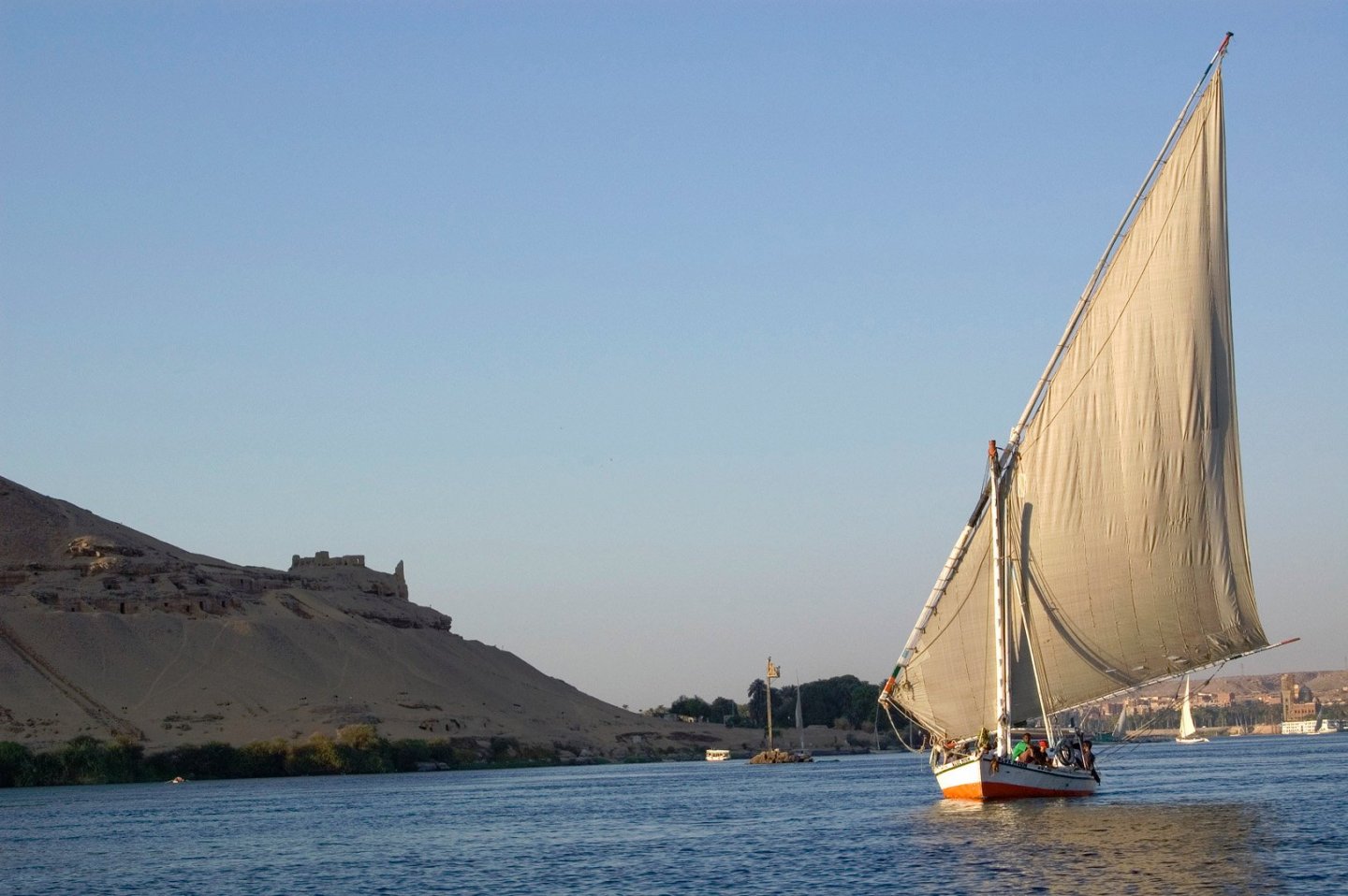

- 41 replies
-
- 13
-
-
- Finished
- Allège d’Arles
- (and 5 more)
-
 Hello all, After a very helpful discussion with several of you here and a very enlightening set of resources provided by @Thanasis, I feel ready to tackle this build that has been haunting me a few years now. It all begins with this image: It's found in a Greek museum of engravings (Benaki museum) and according to it's inscription it depicts a galliot from Psara. It is engraved by Lykourgos Kogevinas, a famous Greek engraver in 1938, but is based on a painting by a Lt E. W. Churchill made in 1827. We can assume the Lt served in the British Royal Navy at the time in the Mediterranean and saw the pirate ship first hand. Now Psara is a small island in the Aegean sea, with a very long nautical tradition. Psarians were very active at sea during the Greek revolutionary war and the island is known for the Psara massacre, performed by the Ottoman army in retaliation for blowing up the ship of a Turkish Admiral. According to the Scottish historian George Finlay, the population of the island was about 7000 before the massacre, but it never rose above 1000 afterwards. The Psarians used galliots, usually of more than 32 oars, as warships and in piracy. They provided a number of such galliots to the fleet of Admiral Alexei Grigoryevich Orlov during the Russo-Turkish War of 1768–74, when the Ottoman fleet was destroyed at the Battle of Chesma. According to Russian sources of the time the galliots were very effective reconnaissance, assault and liaison ships. More to follow soon. George
.jpg.7b5c813a4f222ccca24ede0c225913b3.jpg)
-
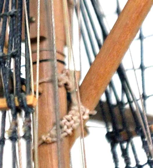
On the Royal William (launched in 1650 and final refit by 1719), the lateen yard is shown in the attached image as being supported by a truss made entirely of rope and not the usual trucks/ ribs that I associate with a parrel. Can anybody throw light on this form of truss. Did it actually exist ? When ? Any information would be appreciated. Pete
-
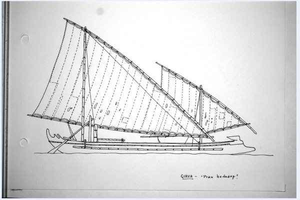
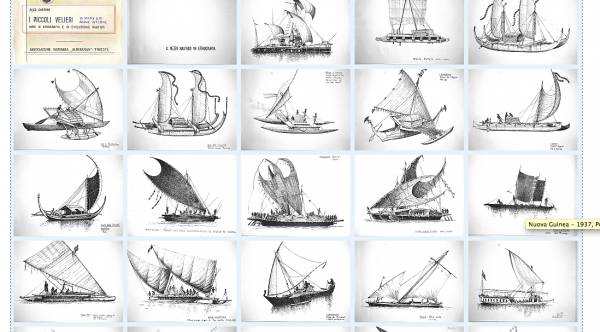
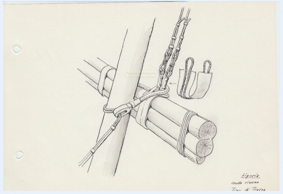
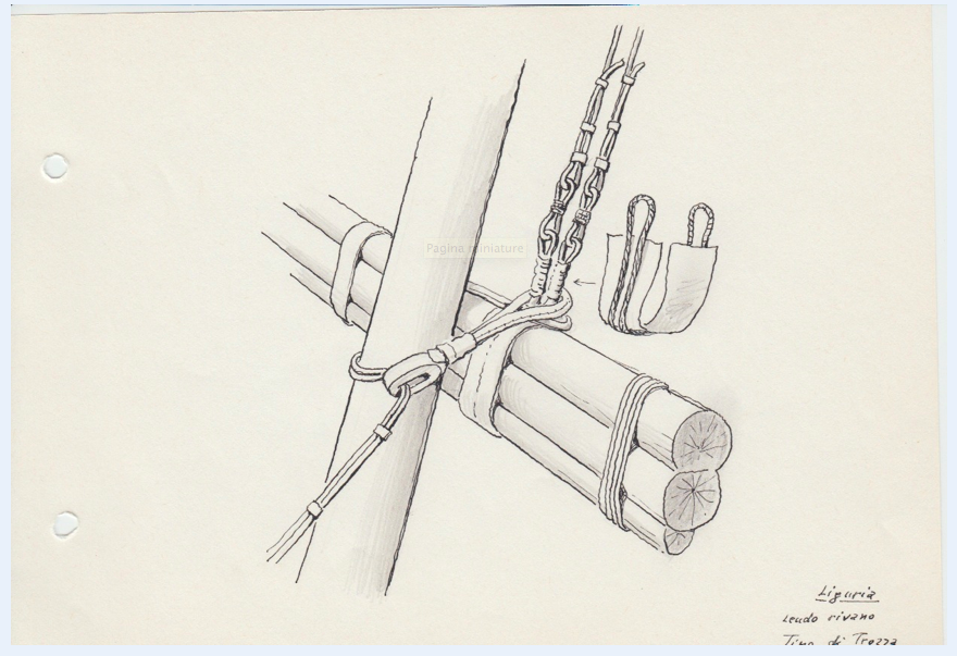
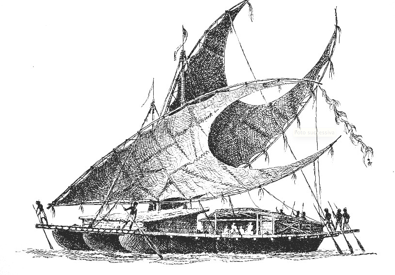
 Found this link on Reddit, looks like13 pages from a sketchbook have been reproduced. http://www.cherini.eu/etnografia/IND/index.html the root website doesn't translate to English but if you click on the hotlinks there is treasure: http://www.cherini.eu/and I do mean TREASURE, I have not seen so much information on delightful non-Western rigs before.