Search the Community
Showing results for tags 'spars'.
Found 5 results
-
I have the usual suspect textbooks: Lee, Marquardt, Zu Mondfeld, Davis. They have mast and yard length and diameter formulae for a number of nations but not Spain (except for Zu Mondfeld but his information is prior to the Napoleonic era and so not helpful .... Spanish spar formula probably changed with the surveyor). With the exception of the periods when the Spanish used English or French methods, is there a source of these formula? My books in Spanish, which I do not naturally read, all appear to provide information on Spars for actual ships (Frigate and above) and that just won't help me mast a brig though I do intend to work backwards and create formula that might be relevant to a brig. On the subject, a general book with Spanish plank sizes, hammock stancions, etc. would really help as well. I have several books by Enrique Garcia-Torralba Perez, books of photos of Museum ships, and a lot of original Royal plans and diagrams (many of which appear in said books as well), so that is how I have been picking up details but I really miss having sources like Goodwin and Lee. TYVM in advance!
-
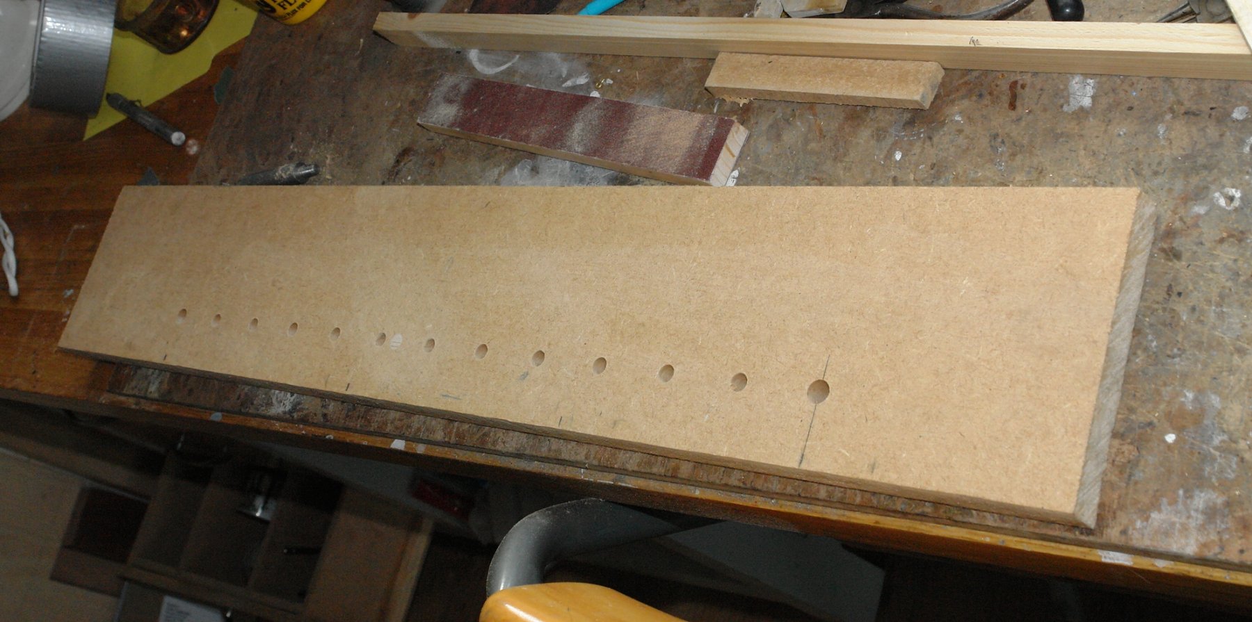
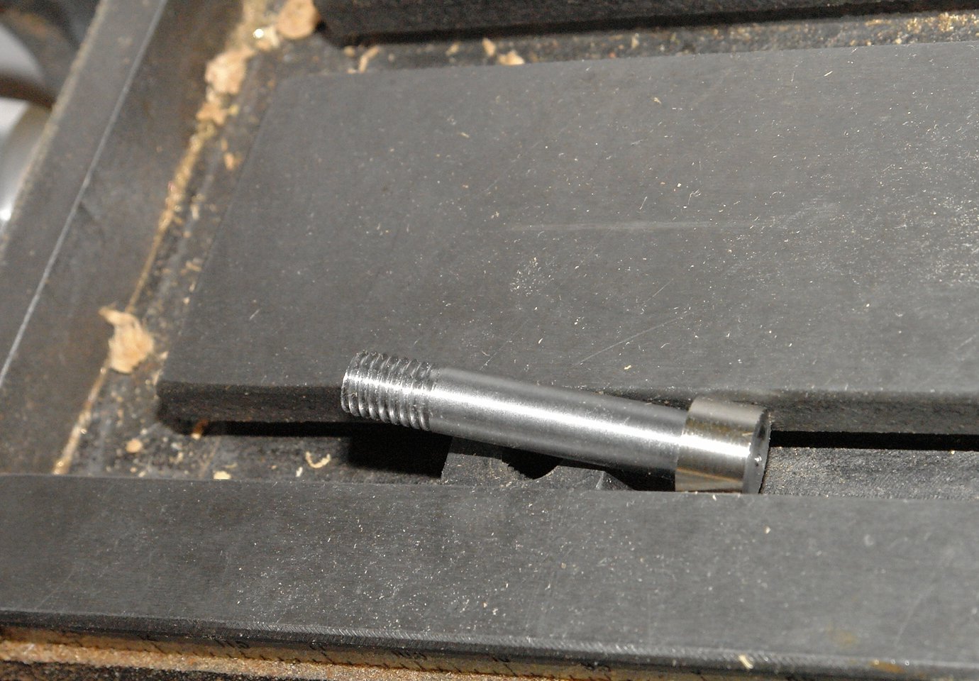
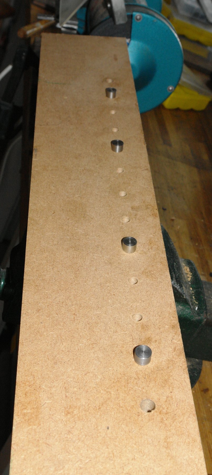
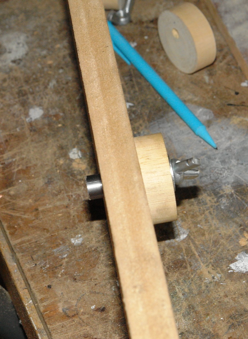
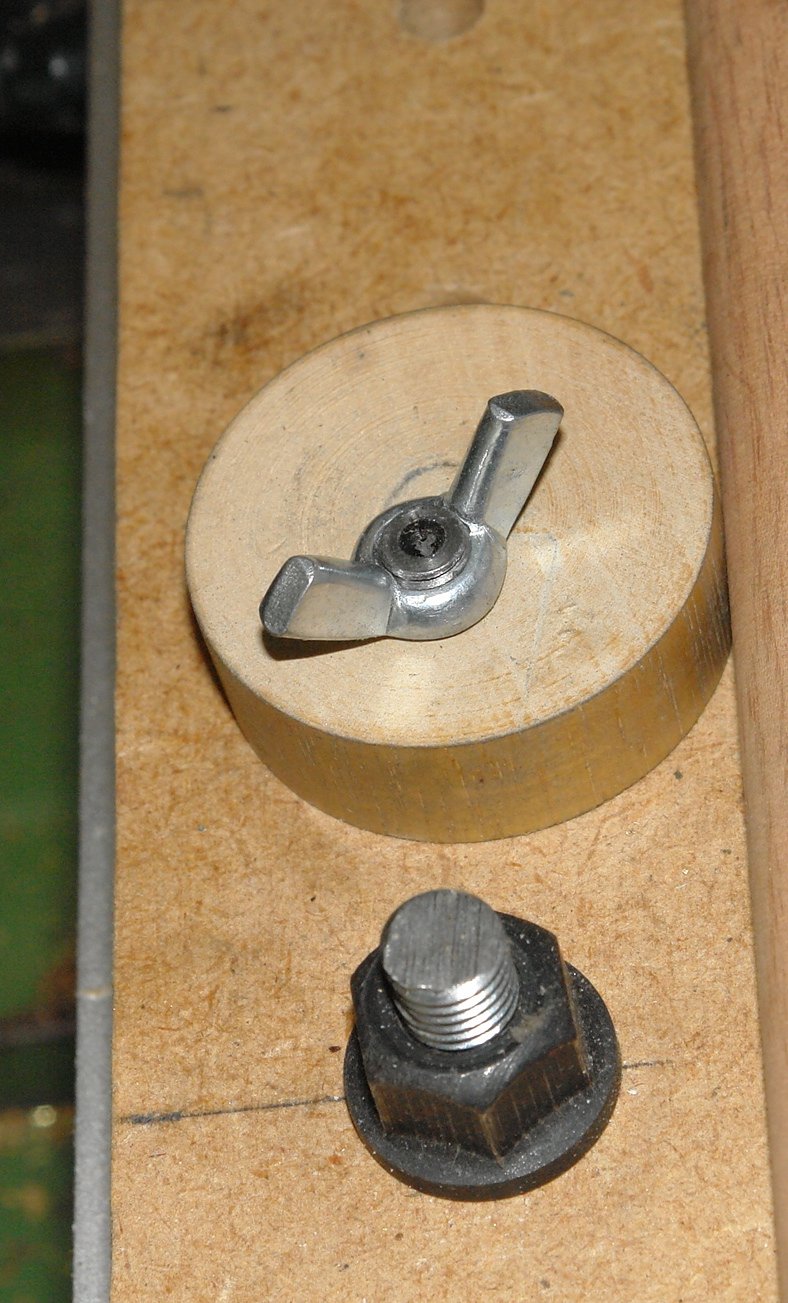
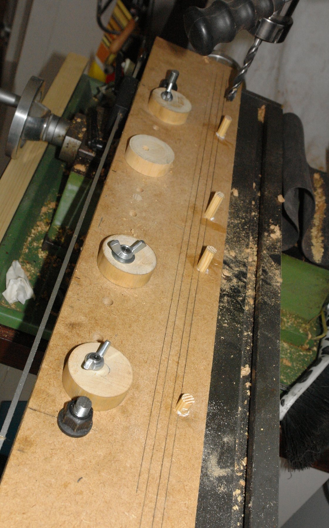
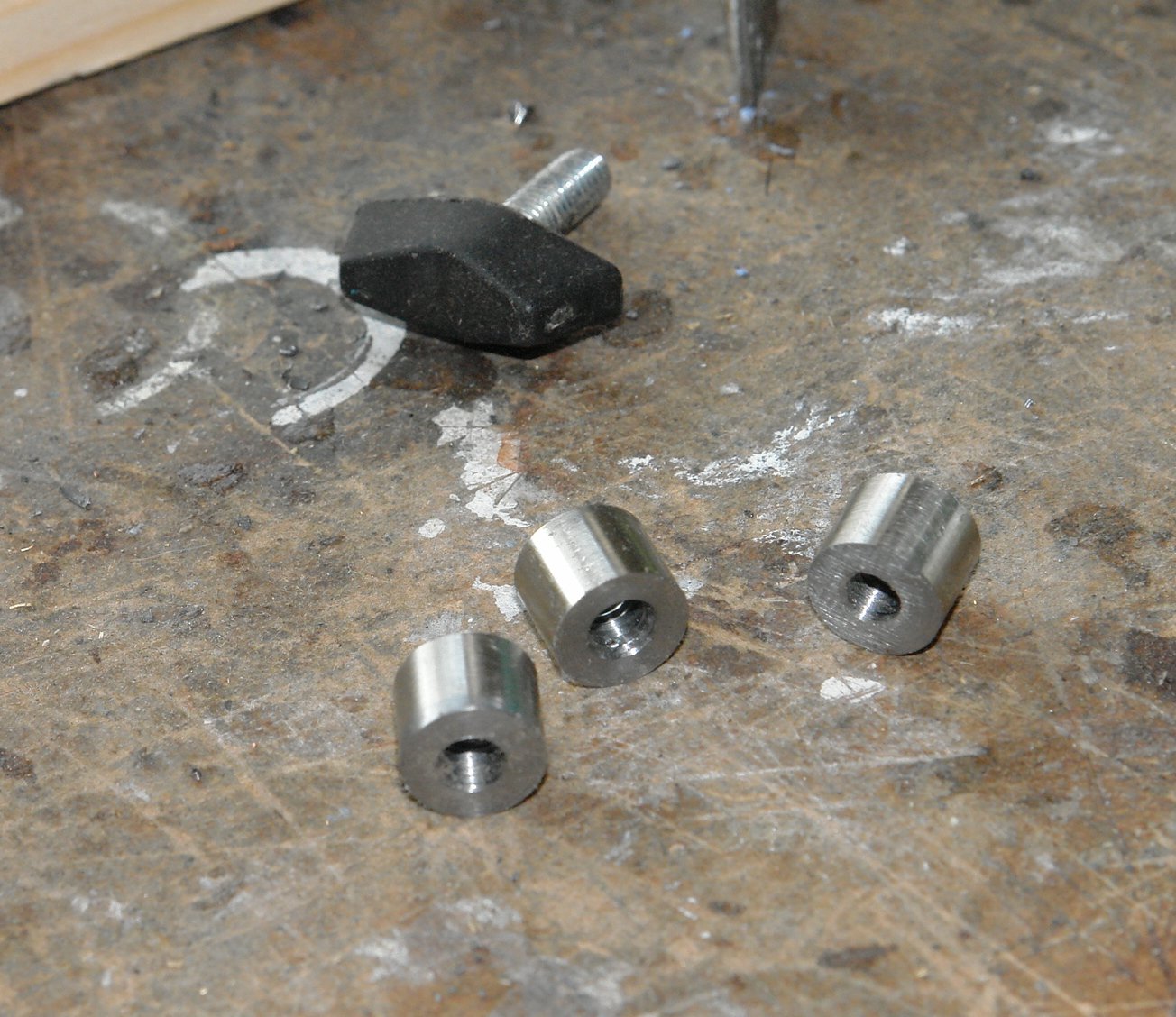
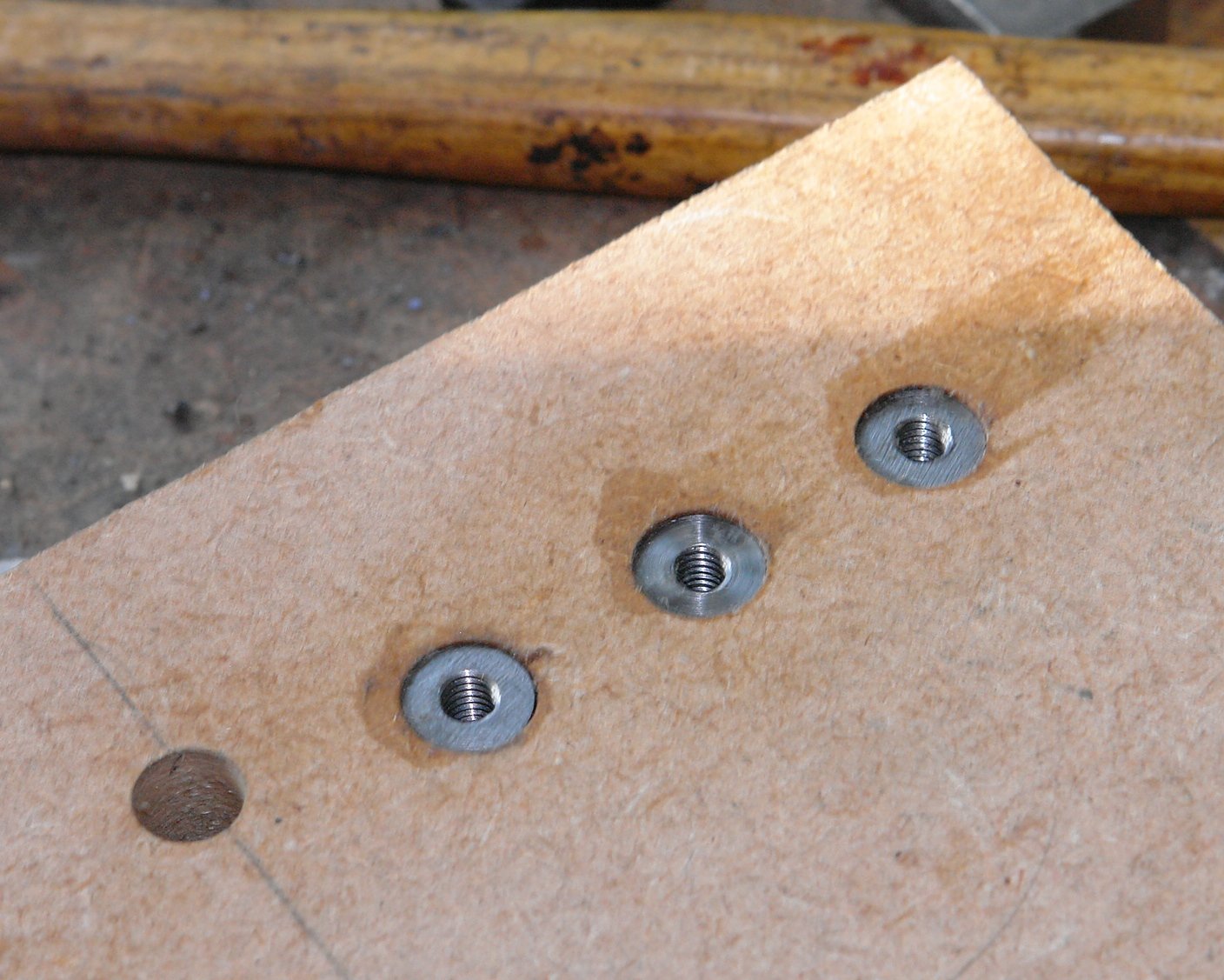
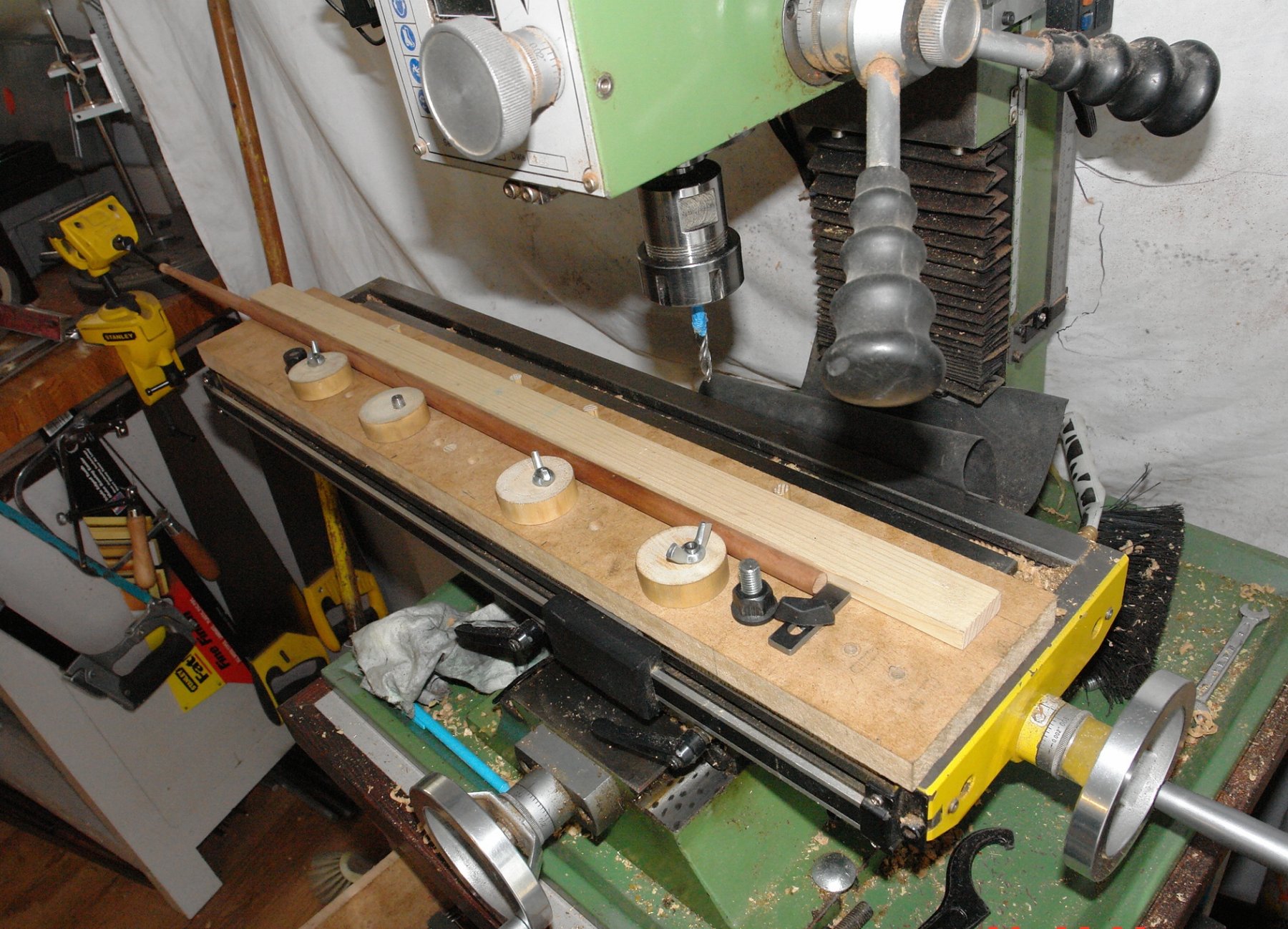
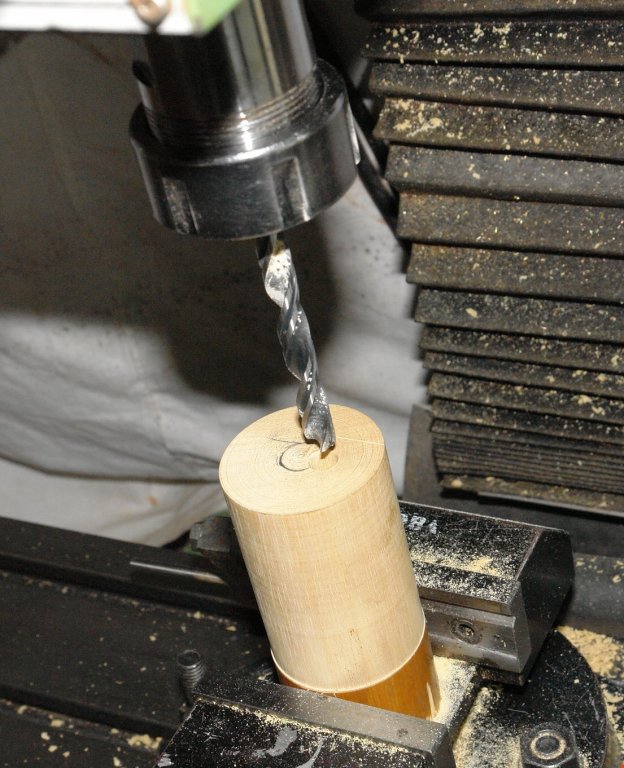
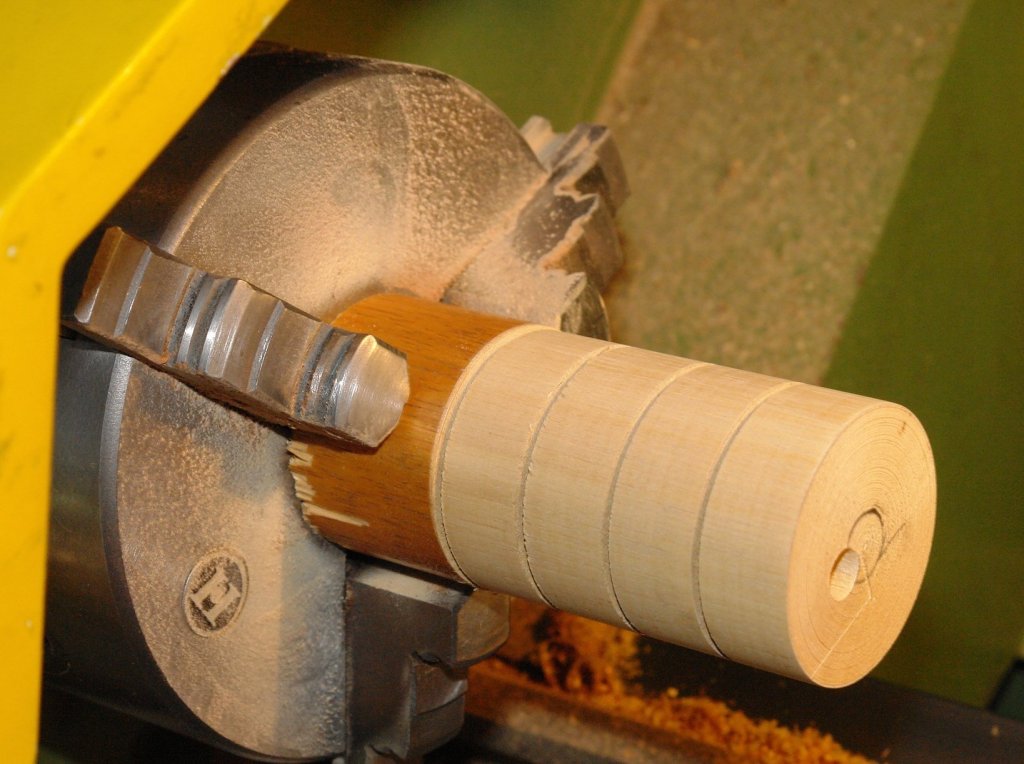
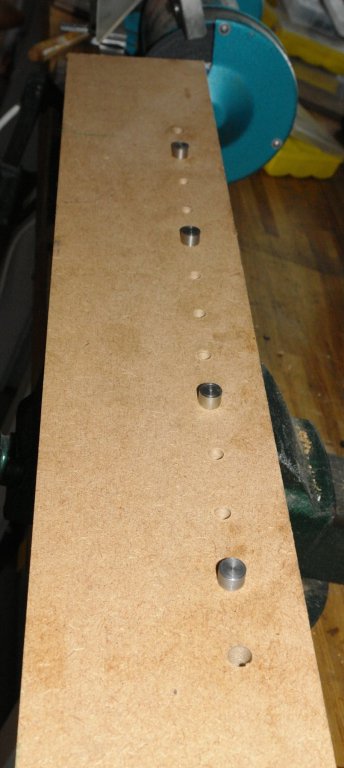
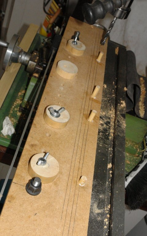
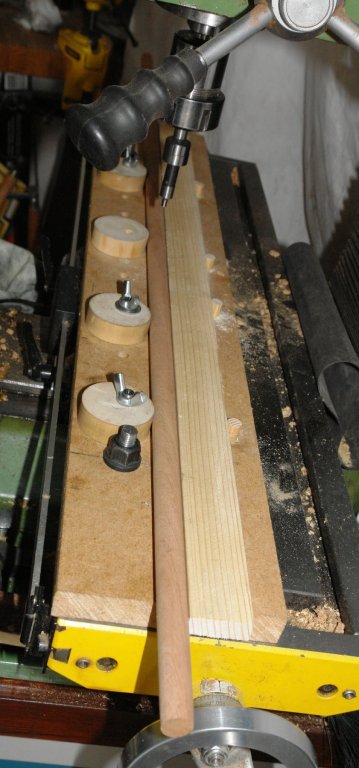
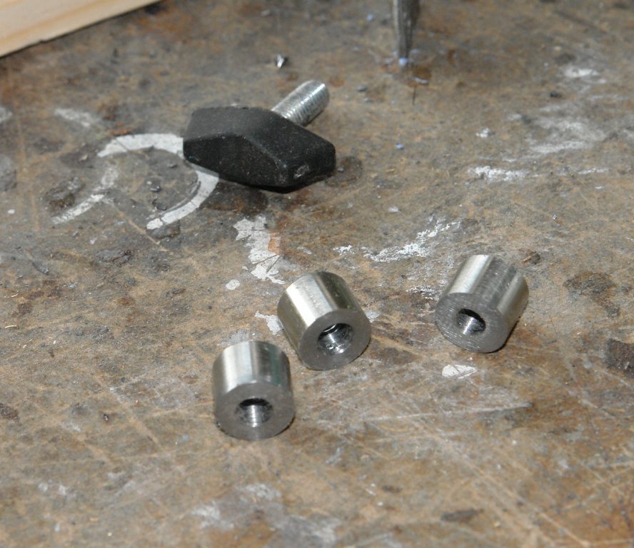
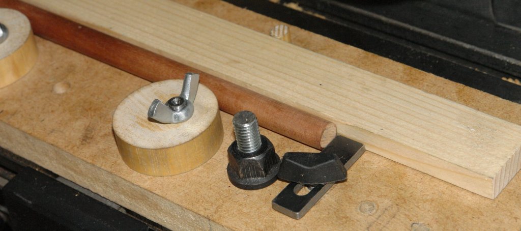
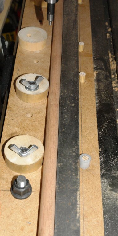
 In the past I have constructed many ad hoc fixtures to enable the accurate machining of masts, spars, yards, booms etc. I decided to have a go at making something more versatile that would work for items of different shapes and sizes. Having made it it seems to work well so I thought it would be worth sharing. I started out with a set of design aspirations. For ease I will refer to "masts" rather than go through the full range of parts each time. 1 Provide solid clamping along the length of the mast. 2 Locate / relocate on the milling table without the need for alignment / set up. 3 Positively locate and relocate the mast so that I can easily remove and replace it on the mill. 4 Clamping devices not to mark / damage the mast. 5 Clamp parallel and taper masts. 6 Clamps to be easy and quick to operate. I started with a clamping concept based upon eccentric circular cams and the build started by cutting a piece of 3/4" MDF to sit on the milling table. I used the mill to accurately drill a series of holes along the length of the MDF to take the cams. The cams themselves were turned (circular) from hardwood. An eccentric hole was drilled along the axis of the cams before they were separated. The cams are mounted on the MDF using a pin. The pin protrudes below the bottom surface of the MDF and the protruding part is cut to a diameter .001" smaller than the slot in the milling table. Once the pins are pushed into the MDF they give positive and repeatable location on the milling bed. The top of the pin locates the cam which is locked by a wing nut. The additional holes allow the cam positions to be varied to suit the mast being worked on. Holes at either end of the MDF take the "T" nut bolts which attach the MDF to the milling table. The MDF was then placed on the milling table (located by the pins) and a row of 4 holes were drilled parallel to the pin holes. Into these holes were placed accurately made dowels. These dowels provide the "fixed" support against which the cams clamp. I think this will become clearer in later photos. A simple piece of wood is then placed up against the dowels. This forms the face against which the mast is clamped. In the following picture a mast is clamped in place. Because the cams act as a finely tapered wedge hand rotation is enough to very rigidly hold the mast. The cams give a lot of flexibility on the diameter of mast that can be held - .200" to .700". But larger is possible by using a narrower wooden strip. At this stage I checked the alignment of the mast to the axis of the mill. The run out was .0015" over a 12" length. Much better than I expected. I did however need an end stop to control the position of the end of the mast. This was relatively easily achieved and for good measure I included an option for 3 positions. See Photos:- The solution to dealing with taper masts is straightforward but does require a bit of trigonometry. The taper is achieved by changing the diameter of one of the fixed dowels. This is done by making a collar to fit over it. This gives a triangle the base of which is the distance between the first and last dowels and the "opposite side" is the thickness of the collar wall = (outside diameter - inside diameter)/2. In the last picture I replaced the wood strip by a steel bar - but this proved to be un-necessary. I still have a few bits to develop but I think thats enough for now - except for the mystery of the missing wing nut!!!!!!


-
Hi guys and ladies I'm still on the furniture stage on the deck of my amati adventure but this will be finished in a couple of weeks. I was wondering of ways to taper the masts , I've considering buying a lathe but i am looking at other ways., as the one i want is about $ 400. Has anyone got a way of tapering masts mine are about 600mm long and 8mm wide .
-
 Hello, I am finishing up the Royal yacht Mary by Mamoli, and working on the masts and spars. They are from basswood and I hate them. They are warped and break easily when you sand them thin. I did some research in the books I have and a website from Gene Larson, on what type of wood to use for mast and spars. They suggest the following: Sitka spruce, lemon wood, lance wood, maple, cherry and red cedar. I need the following diameters and I have put them both in mm and inches. 8mm or 5/16" 7mm or 17/64" 6mm or 15/64" 5mm or 3/16" 4mm or 5/32" 3mm or 1/8" 2mm or 5/64" I have checked the following places for dowels and diameters and types wood They all have the common diameters but not 5/64 or 15/62. http://www.nationalbalsa.com/ http://dlumberyard.com/index.html http://www.hobbymillusa.com/ http://www.modelexpo-online.com/default.asp (they used to have so much more) http://www.woodcraft.com/ Any suggestion of other places I missed that are reliable in the USA. The NET has lots of places that sell dowels and Amazon is connected to many sites I have never heard of. Any suggestions on the type of wood and where to buy is much appreciated. Marc
 -
 Can you just paint wooden dowels, or do you need a primer/base coat first?