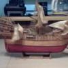
Walter Biles Posted July 5, 2015 Share #1 Posted July 5, 2015 (edited) I recently bought a plan for this America Schooner. The America II was in the US Naval Station on the Severn River when I was there. It was right next to the Meridea then. I did not have the point of perspective that I could do a sketch of it because Meridea was right between. Although the 1/4" plan is pretty good, It only has about 8 stations drawn, and none of them are spaced upon the evenly spaced frame positions, so the only way I can accomplish drawing the frames for her will be to take those station drawings and enter them into CAD and extrapolate each frame from the resulting waterlines. I am interested in working on getting this CAD drawing, but, I have never transitioned into any successful 3D skills with my DesignCAD 2/3D program. I have had an idea of the how to do the plan, but it will take a lot of trial and error before I can get it accomplished, I am sure. I have wanted to do this POF for almost as long as I have been working on Meridea, however, it was all in 2D. The lack of being in 3D caused me to have problems with the drawings in each view being coordinated (may not be the right word). I believe I am going to need some guidance on this one. Does anyone out there have and understand DesignCAD 3D MAX? I will probably need some tips on how to get the move point in a uniform position so when I paste the station into the 3D drawing they will all line up successfully. When I select the intersect of the vertical/horizontal lines the move point is always off to the side. That makes it next to impossible to get the former in exactly the right place. That has been my main problem from the start. I have also had some problems with them showing up in the right plane going from 2D to 3D. The 2D is XY, and when pasting them into the Z position, the front, top, and side views don't seem to come out right. The few times they did, I don't know how I got them there. I do understand layering, so you can hide or show each station. Edited September 17, 2015 by Walter Biles thibaultron 1 Quote Current: America Schooner https://modelshipworld.com/index.php?/topic/10887-america-schooner-pof-by-walter-biles-radio-pof-scale-148-from-blue-jacket-plan/ Prior: MERIDEA https://modelshipworld.com/index.php?/topic/140-meridea-by-walter-biles-radio-34-scratch-cad-of-boat-at-usn-severn-river-repair-station-ca-1969/ SAMSON First build: Scratch POF Spanish Galleon Link to comment Share on other sites More sharing options...
mtaylor Posted July 5, 2015 Share #2 Posted July 5, 2015 Walter, Try asking that here: http://modelshipworld.com/index.php/forum/34-cad-and-3d-modellingdrafting-plans-with-software/ There's also a lot of CAD discussion regarding lofting, etc. here: http://modelshipworld.com/index.php/forum/13-ships-plans-and-scratch-research-general-research-on-specific-vessels-and-ship-types/ in the Scantlings discussion. How's the Meridea coming along? Quote Mark "The shipwright is slow, but the wood is patient." - me Current Build: Past Builds: La Belle Poule 1765 - French Frigate from ANCRE plans - ON HOLD Triton Cross-Section NRG Hallf Hull Planking Kit HMS Sphinx 1775 - Vanguard Models - 1:64 Non-Ship Model: On hold, maybe forever: CH-53 Sikorsky - 1:48 - Revell - Completed Licorne - 1755 from Hahn Plans (Scratch) Version 2.0 (Abandoned) Link to comment Share on other sites More sharing options...
captainbob Posted July 5, 2015 Share #3 Posted July 5, 2015 Sounds like fun Walter. Bob Walter Biles 1 Quote Every build is a learning experience. Current build: SS_ Mariefred Completed builds: US Coast Guard Pequot Friendship-sloop, Schooner Lettie-G.-Howard, Spray, Grand-Banks-dory, a gaff rigged yawl, HOGA (YT-146), Int'l Dragon Class II, Two Edwardian Launches In the Gallery: Catboat, International-Dragon-Class, Spray Link to comment Share on other sites More sharing options...
Walter Biles Posted July 5, 2015 Author Share #4 Posted July 5, 2015 (edited) Hi Mark, It is fairly close to finished for now. I have about 4 or 5 more planks on each side to finish, then some glass work, but for now it is on hold until I can get my truck engine overhauled. We started getting it ready to pull last Saturday, but I got overheated about late morning and had to stop until we can get cooler weather. I am trying to figure out how to learn how to use the 3D part of my DesignCAD program during the heat of the day. I know there must be lots more I could do with it if I can just break through this short term memory problems with learning how to use it. I know there are features available to help, if I could just learn how to use them. Thanks for the tips you provided. I am going to try to find my training disks for this older version since I am more familiar with it. I keep forgetting how I did this or that, and can't find where I found the information to try to work it out. Edited July 5, 2015 by Walter Biles mtaylor 1 Quote Current: America Schooner https://modelshipworld.com/index.php?/topic/10887-america-schooner-pof-by-walter-biles-radio-pof-scale-148-from-blue-jacket-plan/ Prior: MERIDEA https://modelshipworld.com/index.php?/topic/140-meridea-by-walter-biles-radio-34-scratch-cad-of-boat-at-usn-severn-river-repair-station-ca-1969/ SAMSON First build: Scratch POF Spanish Galleon Link to comment Share on other sites More sharing options...
thibaultron Posted July 6, 2015 Share #5 Posted July 6, 2015 3D does take getting used to. Mostly you have to get used to setting points rather than using the mouse as much as with 2D. Quote Ron Thibault Shipjack Carrie Price from Pyro kit, with upgraded detailing and history. Going From A 2D Drawing To A 3D Printed Part Tutorial Link to comment Share on other sites More sharing options...
Walter Biles Posted July 6, 2015 Author Share #6 Posted July 6, 2015 (edited) Ron, Are you familiar with DesignCAD 3D Max? I think It was you that I saw had said they were using it. I have always been using IMSI Since ModelCAD when they first came out with it. In the 1990's I had gotten Version 13, then 14 of DesignCAD 2/3D Max. After I got a new 8.1 HP computer I got DesignCAD version 23, but the HP with MS 8.1 did not even last a year. It was a virus magnet. It is no longer able to be on the internet, and I stopped using it. I hope that the new MS 10 System will be able to overcome the former frailties. I started losing my short term memory while I was trying to learn DesignCAD 14 before I got into 3D, and started having trouble learning new things. I know even this older version had many features I never could use. Now the doctors found my apnea problem and I am using my CPAP, I have started trying to break through into 3D. It had solid modeling features that could help me refine my CAD drawings better if I can just overcome my learning disabilities. I am wondering if you know my program type, even if it is a newer version, I would like to be able to converse with someone I can ask for help. I doubt that I could learn a whole new CAD system now, but if I can get more into the 3D functions to where I can achieve a break through I might be able to use what I have. I would sure appreciate any help you could give. I saw an inkling of more user friendliness in the version 23, but I can not use it on my old low memory computer system. I wish I had selected the Windows 7 version when I got the new computer system. It might still be working if I had. I knew most newer programs needed more hard drive and RAM when I was looking and that was why I decided to go with the newer OS. Now I am sorry for my choice. My budget will not stand constant upgrading and I do not approve of programming with constant fees just to keep using what you have paid for. Version 23 was still buy and use forever if I had a computer that could use it. Edited July 6, 2015 by Walter Biles Quote Current: America Schooner https://modelshipworld.com/index.php?/topic/10887-america-schooner-pof-by-walter-biles-radio-pof-scale-148-from-blue-jacket-plan/ Prior: MERIDEA https://modelshipworld.com/index.php?/topic/140-meridea-by-walter-biles-radio-34-scratch-cad-of-boat-at-usn-severn-river-repair-station-ca-1969/ SAMSON First build: Scratch POF Spanish Galleon Link to comment Share on other sites More sharing options...
thibaultron Posted July 6, 2015 Share #7 Posted July 6, 2015 I've used DesignCAD since the early 90s, both 2D and 3D. I'm using Ver 24 right now. In the recent past I've used V15 & v20. The general commands for all these later versions are about the same. I went from v20 to v24, because I was running into low memory problems with the older versions. I've run v24 on both Windows Vista and Windows 7. If your system ran 8.1, it should have more than adequate memory for v23. What anti-virus are you using on 8.1? I have had great luck with the free version of AVG anti-virus. Have you been running the Windows Update, or have it set for automatic updates? If you can not get on the interne, you may have to reinstall the 8.1, and then run all the updates. Keep running them, letting them install, probably rebooting, then run it again. It may take several times until all of them install, as some have to be installed before a later update can load. I update AVG daily and run the Windows Update, and run a virus scan with AVG, at least once a week, and have not had any virus problem damage my computer. I have gotten a few viruses, but they have been caught. If you can get on the Web to at least get the MS updates, do so. They are offering Win 10 for free to users with Win 7, Win 8, or Win 8.1, starting at the end of the month. If you run the updates, they will automatically ask you if you want the upgrade. I'd be happy to help you. Here are a couple of recent 3D drawings I've done. The first is the Maryland Terrapin Smack from a Chappelle drawing in a book. I'm now redrawing it from the large plans I got from the Smithsonian. The second is a hand powered oyster dredge winch for a Chesapeake Bay Skipjack, I'm building. mtaylor and mikegerber 2 Quote Ron Thibault Shipjack Carrie Price from Pyro kit, with upgraded detailing and history. Going From A 2D Drawing To A 3D Printed Part Tutorial Link to comment Share on other sites More sharing options...
Walter Biles Posted July 11, 2015 Author Share #8 Posted July 11, 2015 (edited) Thanks Bob and Ron, It is fun. I found my training disks for the version 14, but had some trouble with the main program. I still haven't figured out yet how to get by the difficulty. On my version 23 on the 8.1 computer I did get most of the sections moved into the spaces where they belong, I am still figuring out why I can't seem to do the same on the old version. Since the version 14 is no longer supported, all I have is the printed handbook or manual that came with it. Part of the interactive helps that used to go online no longer do so. Trouble is I have forgotten much of the nomenclature to be able to look up the things I need in the manual. Anyway, I may go ahead on version 23, offline, since I can't afford the lockups that occur as soon as I try to start downloading updates. My new computer started dogpile downloading everytime I tried to get a regular update. Even after several online sessions with guru people trying to fix my new one, that still occurred. That is why I stopped going online with it, at all. At least the help option on the newer one works. I got further with positioning them in 3-4 hours than in that many days on the old version. Edited July 11, 2015 by Walter Biles mtaylor and thibaultron 2 Quote Current: America Schooner https://modelshipworld.com/index.php?/topic/10887-america-schooner-pof-by-walter-biles-radio-pof-scale-148-from-blue-jacket-plan/ Prior: MERIDEA https://modelshipworld.com/index.php?/topic/140-meridea-by-walter-biles-radio-34-scratch-cad-of-boat-at-usn-severn-river-repair-station-ca-1969/ SAMSON First build: Scratch POF Spanish Galleon Link to comment Share on other sites More sharing options...
Walter Biles Posted July 12, 2015 Author Share #9 Posted July 12, 2015 (edited) Mark, Thanks for the likes. I am hoping that once I get the stations drafted into the program, I can put on the waterlines and then use them to create intersects that I can create the actual frames which do not necessarily fall on very many of the stations. With them I could get the basic faired frames with the edges sloped to match the hull form. I have found it to be difficult (to say the least given my math skills) to calculate frames from the stations. the only way I could do that is to make them all oversized and file or sand them down using fairing strips. I prefer to fight my way through learning the program features to make it possible for me to use the program in the future. Losing my math skills stinks. I had thought that It would be easier to do the math in metric, but my mind just can't make the transition to envision things in that format. I guess I am stuck with feet and inches and letting a program do all the math if I can just learn some more about my CAD program. I need to start jotting the page numbers in the manual onto a tablet with verbal descriptions and nomenclature I find from the book, until the references become re-findable through repetition until my mind can find the right commands to use to do a certain task. That way I may be able to break through into doing 3D. If anyone reading this should even suspect that they might have sleep apnea, by all means get a doctor to help you get tested before it gets too bad. You do not want to try to live with the damage it would do to your memory and learning skills. OKAY? YOUR LIFE COULD BE AT RISK. Sometimes you do not wake up from trying to sleep without the help. Ever!!!! Edited July 12, 2015 by Walter Biles Omega1234, mtaylor, thibaultron and 1 other 4 Quote Current: America Schooner https://modelshipworld.com/index.php?/topic/10887-america-schooner-pof-by-walter-biles-radio-pof-scale-148-from-blue-jacket-plan/ Prior: MERIDEA https://modelshipworld.com/index.php?/topic/140-meridea-by-walter-biles-radio-34-scratch-cad-of-boat-at-usn-severn-river-repair-station-ca-1969/ SAMSON First build: Scratch POF Spanish Galleon Link to comment Share on other sites More sharing options...
Walter Biles Posted July 15, 2015 Author Share #10 Posted July 15, 2015 (edited) Ron, I am wondering if the 2D drawing needs changed from XY to one or the other of the other sets. I made the Stations in 2D because the Left-right sides would be on either sides of the X plane. That would mean that the Up-down plane would be on the Y plane. When I started putting them into the 3D they came out correct, and I just had to make a grid of lines to space them out along the keel line. However, I am drawing the side view of the hull now and putting it into the same XY format from the 2D. How is it going to display in 3D? do I need to set the 2D drawing to XZ to get it in the right plane to fit into my first 3D. Does that setting need to be made before any drawing is done on the side view drawing? I don't remember my previous experiences, but I seem to recall they were all messed up. Edited July 15, 2015 by Walter Biles Quote Current: America Schooner https://modelshipworld.com/index.php?/topic/10887-america-schooner-pof-by-walter-biles-radio-pof-scale-148-from-blue-jacket-plan/ Prior: MERIDEA https://modelshipworld.com/index.php?/topic/140-meridea-by-walter-biles-radio-34-scratch-cad-of-boat-at-usn-severn-river-repair-station-ca-1969/ SAMSON First build: Scratch POF Spanish Galleon Link to comment Share on other sites More sharing options...
Jond Posted July 15, 2015 Share #11 Posted July 15, 2015 Hi Walter I am in later stages of struggling with same scale 1:48 to make a radio sailing 4 masted schooner. I will enjoy watching and learning from your log. I see you are talking 3D ..... wow. I have switched to Turbocad which is relatively easy to learn and not expensive. However i stayed in 2D for my build...the comfort zone I hope to learn from builds like yours so I can go to 3D good luck....i will be watching cheers Quote current build Beam Trawler Harvard 1926 Lightships of Boothbay. WAL 605 Overfalls ;Blue Dolphin Maine_ Arctic Schooner ; H G Berry_ Brigs of Boothbay; first pinky in Boothbay diorama; Bluenose 1:24 ; ernestina-morrissey-by-jond-1:48; aphrodite 1853 1st ship in boothbay ; Bowdoin diorama; dancing feather 1853 pilot schooner RC ; Boothbay Harbor One design racing sloop 1:6 radio Charles Notman 4 masted Downeast schooner 1:48 radio Link to comment Share on other sites More sharing options...
Walter Biles Posted July 15, 2015 Author Share #12 Posted July 15, 2015 (edited) Hi Jond, I had severe Sleep Apnea until I was forced out of working after my points had been reached. The oxygen deprivation killed parts of the brain and it's links. I have found this exercize to be beneficial once my CPAP treatments got me away from nightly low levels of O2 for most of each night. I have recovered some things that I had once learned. However the damage to my short term memory caused learning something new to be a very hard thing. With exercises of body and mind I have regained many of my old links to old memories. The damage to my short term memory causes great problems. Since what I try to learn can't stay there long enough to get to my long term memories. My math skills which used to be very good, are next to zip. I cannot remember one math operation long enough to carry it through to starting the next step. That has not improved. Therefore, I am having to work through the 3D a bit at a time, on my same version of DesignCAD or a newer one, hoping it will stick long enough for me to use any of it. If I can gain any proficiency in DesignCAD 3D from where I had learned, Then I may be able to learn 3D. I had never gotten that far before the damage. I know the program has many different tools that would probably make it easier to resolve the designs. I am dying to be able to do some of the tasks that are described as possible in the 3D. It is likely to be a long row for me to hoe before I can start planting, if you can understand. A new program would present me with a much longer list of things to try to learn before I could start into 3D. I have found that hammering away at the familiar will sometimes open things up a little bit, and if I keep at it and keep my usage progressing, then sometimes I can start remembering that little bit. I just have to keep on hammering away at it. I think that if I can actually get through to getting the boat into 3D, that I will have gained a new tool to use in my hobby. Otherwise, I have gone as far as I can. Main thing is, I want to be able to use this program. Once I get the boat completed in CAD, I am hoping to blow it up to 1:24 scale for the RC part. My Meridea is 1:13 but is much wider. Also the hull tapers in toward the center quicker than my Meridea. I will probably try framing the hull in 1:48 first, but I don't think that this boat in 1:48 will be wide or deep enough for the controls to go in. I am glad you have the use of TurboCAD. I wish you the best. Edited July 15, 2015 by Walter Biles thibaultron and mtaylor 2 Quote Current: America Schooner https://modelshipworld.com/index.php?/topic/10887-america-schooner-pof-by-walter-biles-radio-pof-scale-148-from-blue-jacket-plan/ Prior: MERIDEA https://modelshipworld.com/index.php?/topic/140-meridea-by-walter-biles-radio-34-scratch-cad-of-boat-at-usn-severn-river-repair-station-ca-1969/ SAMSON First build: Scratch POF Spanish Galleon Link to comment Share on other sites More sharing options...
Walter Biles Posted July 15, 2015 Author Share #13 Posted July 15, 2015 Thanks for the Like Mark. I am using this CAD work as further therapy for my mind. I sure hope it pays off. That interference tool is one I am excited about being able to use. That and being able to get the boat into 3D so I can visualize things better. Also, it would be interesting to be able to use the walk through facilities that this program has talked about. That should make some sort of mishap inside show up before I go to the building table. Quote Current: America Schooner https://modelshipworld.com/index.php?/topic/10887-america-schooner-pof-by-walter-biles-radio-pof-scale-148-from-blue-jacket-plan/ Prior: MERIDEA https://modelshipworld.com/index.php?/topic/140-meridea-by-walter-biles-radio-34-scratch-cad-of-boat-at-usn-severn-river-repair-station-ca-1969/ SAMSON First build: Scratch POF Spanish Galleon Link to comment Share on other sites More sharing options...
mtaylor Posted July 16, 2015 Share #14 Posted July 16, 2015 I've not used CAD except for AutoCAD back in the 80's. And even then, not much. But any learning is good for the mind, right? I hope so.. my learning curves lately have been pretty steep. Omega1234 1 Quote Mark "The shipwright is slow, but the wood is patient." - me Current Build: Past Builds: La Belle Poule 1765 - French Frigate from ANCRE plans - ON HOLD Triton Cross-Section NRG Hallf Hull Planking Kit HMS Sphinx 1775 - Vanguard Models - 1:64 Non-Ship Model: On hold, maybe forever: CH-53 Sikorsky - 1:48 - Revell - Completed Licorne - 1755 from Hahn Plans (Scratch) Version 2.0 (Abandoned) Link to comment Share on other sites More sharing options...
thibaultron Posted July 16, 2015 Share #15 Posted July 16, 2015 (edited) After generating the hull lines, I go to 3D mode, draw out the base line, waterline, whatever you are using to determine the fore aft positions of the hull lines in the X direction. Then I rotated the hull lines 90 deg. so they run in the XZ rather than XY direction. Each "frame' is then positioned at its repective place on the reference line. you now have the 3D model of your hull. The following pictures are screen captures of "The Maryland Terrapin Smack 1886" that I drew: This is the station lines, keel, and deck center line laid out in the X axis. In this I've loaded in the frames, rotated them into the XZ plane, and have move some of them onto their locations. Note that this boat has a flat bottom and slab sides, but a regular curved hull is done the same way. Here the frames and transom are all in place, and I have used a curve line with defining points set at each frame to define the Chine and Shear. Much further down the line, I have added surfaces, deck furniture, etc. These are all half hulls, but all it takes then is to duplicate and mirror the finished side, then stick them together. These drawings were made from a scanned page in a book. I've since purchased the full sized plans, and started over to make a more accurately scaled drawing. I'm just starting the 3D drawings for this. There are many other layers of details that are not shown. At this time I am concentrating on Chesapeake Bay boats, for scratch building future models. In the pasted I've CADed 2D drawings of WWII era ships, for semi-scale 144th scale models (to scale, but lacking fine detailing). Edited July 16, 2015 by thibaultron Omega1234, mikegerber, Walter Biles and 1 other 4 Quote Ron Thibault Shipjack Carrie Price from Pyro kit, with upgraded detailing and history. Going From A 2D Drawing To A 3D Printed Part Tutorial Link to comment Share on other sites More sharing options...
Walter Biles Posted July 16, 2015 Author Share #16 Posted July 16, 2015 (edited) Ron, Thanks for showing the stages. I had made the stations mirrored already. I wonder if that would be easier lining things up. I have noticed something called (I think) solid subtract. I still haven't learned to make the hull a solid yet though. There are so many more features that it would be wonderful to learn. I am going to study your drawings for awhile, and see if I can make mine come out like yours. Then I may have some more questions about how to do some things. Thank you so much for your assistance. Having some help like this could make all the difference. Edited July 16, 2015 by Walter Biles Quote Current: America Schooner https://modelshipworld.com/index.php?/topic/10887-america-schooner-pof-by-walter-biles-radio-pof-scale-148-from-blue-jacket-plan/ Prior: MERIDEA https://modelshipworld.com/index.php?/topic/140-meridea-by-walter-biles-radio-34-scratch-cad-of-boat-at-usn-severn-river-repair-station-ca-1969/ SAMSON First build: Scratch POF Spanish Galleon Link to comment Share on other sites More sharing options...
thibaultron Posted July 16, 2015 Share #17 Posted July 16, 2015 (edited) The 3D hull in the above drawing, is not solid, I used surfaces between the frames to give the look of solid, so I could see what she looked like. DesignCAD does not extrude a solid thing. It just make tall 2D walls, with no top or bottom surface, so I can't for example extrude a keel outline to 1/8" thick, and then operate on it like it was a regular 3D thing. The solid drawing shapes like a box or cylinder work just fine with solid add, subtract, and the other operators, but not extruded objects. That is the point I am at now with my new drawing of the boat above. I have to relearn AutoCAD (which I have an old copy of), in order to extrude a solid keel and frames. Then I'll import them into DesignCAD to continue. Why not just use the AutoCAD? It's an old copy, and I expect every new version of Windows to not run it, so far they have, but I'm familiar with DesignCAD, and can afford to upgrade it now and then, I'll never be able to afford a new copy of AutoCAD. DesignCAD is almost as good, just not in the Extrude operation. To illustrate this I have two drawings. The first is a random 2D polygon I generated, then extruded, with a box I made using the Solids menu. The box is of course, on the left, the polygon on the right. The second drawing is the above with using the "Hidden Line Removal" command. The box came out correct, but not the extruded shape. I can save a 2D projection, and remove the extra lines, and have, but I can't just do it automatically. Here are examples of that: The 3D drawing with hidden lines removed. The inner bands are 3D solids – Tubes, the outer band is an extruded shape, notice that the walls of the inner bands were not hidden, as the extrusion has no top surface. The end piece is generated from adding and subtracting solids, and also came out correct. This is the 2D projection drawing, as it was generated. Here it is after I cleaned it up by hand. Edited July 16, 2015 by thibaultron Omega1234, Walter Biles and mikegerber 3 Quote Ron Thibault Shipjack Carrie Price from Pyro kit, with upgraded detailing and history. Going From A 2D Drawing To A 3D Printed Part Tutorial Link to comment Share on other sites More sharing options...
thibaultron Posted July 16, 2015 Share #18 Posted July 16, 2015 THe dedge winch drawing in an earlier post, is also a cleaned up 2D projection. Omega1234 1 Quote Ron Thibault Shipjack Carrie Price from Pyro kit, with upgraded detailing and history. Going From A 2D Drawing To A 3D Printed Part Tutorial Link to comment Share on other sites More sharing options...
Walter Biles Posted July 20, 2015 Author Share #19 Posted July 20, 2015 (edited) Well, I was making progress. Just as I got the next to last frame put into the new 23 version, something, happened, I am not sure what, and the front view dissappeared. Since I was using that one to check for positioning, and I can't find a way to make it come back, I am stuck. I may have to back up and redo all of them from an earlier save. NUTS Just another day at the computer. Now just where did those earlier and later saves go? I wish these programs would quit putting saves in some other part of the computer. Edited July 20, 2015 by Walter Biles mtaylor 1 Quote Current: America Schooner https://modelshipworld.com/index.php?/topic/10887-america-schooner-pof-by-walter-biles-radio-pof-scale-148-from-blue-jacket-plan/ Prior: MERIDEA https://modelshipworld.com/index.php?/topic/140-meridea-by-walter-biles-radio-34-scratch-cad-of-boat-at-usn-severn-river-repair-station-ca-1969/ SAMSON First build: Scratch POF Spanish Galleon Link to comment Share on other sites More sharing options...
mtaylor Posted July 20, 2015 Share #20 Posted July 20, 2015 Walt, Try this... open an "new" drawing and hit "save as". It will open the "save" window at the last folder... although depending the program, it might open the folder at the default location. Otherwise, you can hit the start menu and if you remember the name of the drawing, enter it in the search bar. If not the name, then try *.XXX where xxxx is file type. Walter Biles 1 Quote Mark "The shipwright is slow, but the wood is patient." - me Current Build: Past Builds: La Belle Poule 1765 - French Frigate from ANCRE plans - ON HOLD Triton Cross-Section NRG Hallf Hull Planking Kit HMS Sphinx 1775 - Vanguard Models - 1:64 Non-Ship Model: On hold, maybe forever: CH-53 Sikorsky - 1:48 - Revell - Completed Licorne - 1755 from Hahn Plans (Scratch) Version 2.0 (Abandoned) Link to comment Share on other sites More sharing options...
Walter Biles Posted July 20, 2015 Author Share #21 Posted July 20, 2015 Mark, It was just the 3D Front view. The Side, Top, and Main are still listed in the Windows section. I was being pretty careful not to hit the X button so I wouldn't lose one, but I bumped the keyboard and something else came up. That menu I did want to close, but when The 3D views came back, the Front view was gone. It's like it closed both. Is there anywhere those different veiws are kept? I was using DesignCAD 23. mtaylor 1 Quote Current: America Schooner https://modelshipworld.com/index.php?/topic/10887-america-schooner-pof-by-walter-biles-radio-pof-scale-148-from-blue-jacket-plan/ Prior: MERIDEA https://modelshipworld.com/index.php?/topic/140-meridea-by-walter-biles-radio-34-scratch-cad-of-boat-at-usn-severn-river-repair-station-ca-1969/ SAMSON First build: Scratch POF Spanish Galleon Link to comment Share on other sites More sharing options...
Walter Biles Posted July 21, 2015 Author Share #22 Posted July 21, 2015 (edited) Ron, is there any way to retrieve a view in 3D that unintentionally got closed? Now it is closed I can't figure out how to re-open it. all the data is still in the files, it just does not open that FRONT view. It no longer shows in the Window display of available views. Edited July 21, 2015 by Walter Biles Quote Current: America Schooner https://modelshipworld.com/index.php?/topic/10887-america-schooner-pof-by-walter-biles-radio-pof-scale-148-from-blue-jacket-plan/ Prior: MERIDEA https://modelshipworld.com/index.php?/topic/140-meridea-by-walter-biles-radio-34-scratch-cad-of-boat-at-usn-severn-river-repair-station-ca-1969/ SAMSON First build: Scratch POF Spanish Galleon Link to comment Share on other sites More sharing options...
Walter Biles Posted July 21, 2015 Author Share #23 Posted July 21, 2015 (edited) Ron, QUOTE:After generating the hull lines, I go to 3D mode, draw out the base line, waterline, whatever you are using to determine the fore aft positions of the hull lines in the X direction. Then I rotated the hull lines 90 deg. so they run in the XZ rather than XY direction. Each "frame' is then positioned at its repective place on the reference line. you now have the 3D model of your hull. END QUOTE You say you draw the hull lines, and I assume the station positions along it You rotated the hull so the lines display in the XZ rather than the XY direction. I am having trouble figuring out what steps to do to do what you said. Could you walk me through the steps in the program? Edited July 21, 2015 by Walter Biles mtaylor 1 Quote Current: America Schooner https://modelshipworld.com/index.php?/topic/10887-america-schooner-pof-by-walter-biles-radio-pof-scale-148-from-blue-jacket-plan/ Prior: MERIDEA https://modelshipworld.com/index.php?/topic/140-meridea-by-walter-biles-radio-34-scratch-cad-of-boat-at-usn-severn-river-repair-station-ca-1969/ SAMSON First build: Scratch POF Spanish Galleon Link to comment Share on other sites More sharing options...
thibaultron Posted July 21, 2015 Share #24 Posted July 21, 2015 In DesignCAD You can try Control-Shift-R. This will refresh all the screens, not just the one you are on. Or Control -Shift-W, this will resize the drawing in all the windows to fit the entire drawing in them. If you lost one of the 3D window panes, the menu option "Windows", "DesignCAD Tile Settings", "Restore DesignCAD Tile" will restore the screen to the 4 windows of the standard 3D setup. Walter Biles and mtaylor 2 Quote Ron Thibault Shipjack Carrie Price from Pyro kit, with upgraded detailing and history. Going From A 2D Drawing To A 3D Printed Part Tutorial Link to comment Share on other sites More sharing options...
captainbob Posted July 21, 2015 Share #25 Posted July 21, 2015 I don't know about this software but you might look in the trash folder. Bob mtaylor 1 Quote Every build is a learning experience. Current build: SS_ Mariefred Completed builds: US Coast Guard Pequot Friendship-sloop, Schooner Lettie-G.-Howard, Spray, Grand-Banks-dory, a gaff rigged yawl, HOGA (YT-146), Int'l Dragon Class II, Two Edwardian Launches In the Gallery: Catboat, International-Dragon-Class, Spray Link to comment Share on other sites More sharing options...
thibaultron Posted July 22, 2015 Share #26 Posted July 22, 2015 I posted the drawings in a previous post, refer back to them for this post. I draw the keel and/or fore and aft baseline in the XY, marking the station lines along this line going from the baseline up in the Y direction. Then I paste in the frames/hull stations, which will be shown laid out in the XY (facing you). I rotate each frame around the Y axis, so that it is now in the XZ plane, perpendicular to the keel/baseline. Then move each frame to its corasponding location. I'll post a step by step tomarrow, its 10:20 PM now. Quote Ron Thibault Shipjack Carrie Price from Pyro kit, with upgraded detailing and history. Going From A 2D Drawing To A 3D Printed Part Tutorial Link to comment Share on other sites More sharing options...
Walter Biles Posted July 22, 2015 Author Share #27 Posted July 22, 2015 (edited) Thanks Ron. I just don't understand how you are rotating each frame. There are oodles of commands I had never figured out before. Now I am having trouble on how to do things. If I can reach a break through and practice it enough I feel sure I can learn to do this. Once I get the stations in 3d, then I will have to create each frame position and shape. That will make another 32 times of practice. 42 times in all. Thank you so much for offering me your help. I didn't know when I got DesignCAD 3D Max, that it would be so seldom used between so many users of CAD. Luckily I do have version 23 to practice with. I hate having that computer so messed up that the only time I can use it is if it is off-line. I tried today to go on Utube to be able to hear the instructions for a certain tool construction, and I had HP, MS and my computer all screaming at me that my computer was putting my security at risk, so I had to log back off. The sound card has been blown on my old one for years. At least it's troubles are more passive. Edited July 22, 2015 by Walter Biles Quote Current: America Schooner https://modelshipworld.com/index.php?/topic/10887-america-schooner-pof-by-walter-biles-radio-pof-scale-148-from-blue-jacket-plan/ Prior: MERIDEA https://modelshipworld.com/index.php?/topic/140-meridea-by-walter-biles-radio-34-scratch-cad-of-boat-at-usn-severn-river-repair-station-ca-1969/ SAMSON First build: Scratch POF Spanish Galleon Link to comment Share on other sites More sharing options...
thibaultron Posted July 22, 2015 Share #28 Posted July 22, 2015 (edited) Going from the 2D drawing to a 3D drawing. This will be in at least 2 parts, as I have too many drawings to fitt in one post. Above is the drawing I’m going to start from. I have developed the frames on the upper right to individual frames, on another layer, as part of this drawing. Here is the layer with the frames. I have selected them all, and am making them a group, using the menu selection shown. Making them a group makes them basically one thing/entity. The CAD program will act on all of the grouped lines as a single thing, not separate lines. I’ve now gone to the 3D mode, by selecting the 3D button in the menu system. Note that the lines are still in the proper relationship, as shown in the upper left window. The lines look skewed in the main window, because we are looking down and a little to the side. Note the 3D viewing angle settings in the lower right bottom main menu. If all the settings are at zero, the drawing is displayed as if it was a 2D drawing. You have to crank in some values so that you can see the 3D view. The baselines, fore and aft parallels, and the station lines have been drawn, along the XY plain (Z=0). The red lines are the baseline, and parallels. The green lines are the waterline, and station lines. These are actually the ones from the 2D drawing, I’ve just turned on those layers. All the 2D lines you drew will be displayed on the XY plain in 3D. Placing different sections of the drawing on different layers allows you to hide those layers when working on another section. For example the station lines and baselines are on different layers. I hid them when I was working on the spars, to cut down on the clutter on the screen. Once again you can see that they are not skewed in the Top, Side, and Front views. In this picture I’ve turned on the layer with the completed frames. The curve lines are the deck, with the camber. Here the frames are all selected, and made a group. I have also made the baseline, etc. a separate group. I cleared the selection, and reselected the frame group, at one of the intersections of the baselines. The selected point is the solid dot. The square boxes are the individual line end points. There is an option in the “Options” menu “Point Select Mode” that turns this on and off, if you don’t want it. I forgot to save the screen when I was rotating the frames, so the above drawing is the main one. I selected some lines, and am getting ready to rotated them. This picture is to show how to get to the rotate command. When you select rotate this new menu window pops up. We want to rotate the frames to be perpendicular to the baseline, so select rotate around Y axis, enter 90 deg. For the rotation angle, and deselect the “Drag Mode” option. Now when you move your cursor away from the box, it will be displayed as a curved line and arrow symbol. Move the symbol to the main windows, and click. I could not get the screen capture to show this symbol. The frames have been rotated, and the frame group is being broken, so that we can work on the individual frames. Edited July 22, 2015 by thibaultron Walter Biles and mtaylor 2 Quote Ron Thibault Shipjack Carrie Price from Pyro kit, with upgraded detailing and history. Going From A 2D Drawing To A 3D Printed Part Tutorial Link to comment Share on other sites More sharing options...
thibaultron Posted July 22, 2015 Share #29 Posted July 22, 2015 Part 2 of 2D to 3D This is the front view window expanded. We need to change the frames from the group we made earlier, so that we can move the individual ones. Select a point anywhere on the frames, and going back to the “Tools – Groups menu select “Break Group”. Now I have selected just the lines for one frame, and made them a group. Note that the solid dot is in the middle of the frame, this means that the group was selected by clicking somewhere inside the group boundaries. The frame is pointed in the “wrong” direction, I am placing all the frames on the starboard side to build the hull, and this one would end up on the port side. Deselect the frame group, and reselected it at the crossing of the baselines. Now I have to mirror the frame to reverse it. The above picture shows the menu selections to do this. As this is the front view I have to mirror it on the Z axis. I generally pick the wrong axis, and have to redo it until I pick the right one. I use the “Make A copy” option, that way I’m not risking the original, if I make a mistake. The black frame is the mirrored copy, that is displayed when you move your cursor off of the menu box. The mirrored frame will move with the cursor, until you click the mouse, then it will be dropped on the drawing where the mouse was. There is the mirrored frame. If the original was a group the mirrored one will also be a (separate) group. mtaylor and Walter Biles 2 Quote Ron Thibault Shipjack Carrie Price from Pyro kit, with upgraded detailing and history. Going From A 2D Drawing To A 3D Printed Part Tutorial Link to comment Share on other sites More sharing options...
thibaultron Posted July 22, 2015 Share #30 Posted July 22, 2015 (edited) Part 3 of 2D to 3D Deselect the original and select the new frame, at the crossing of the baselines (shown by the solid dot after selecting.) I have restored the 3D windows, and I’m getting ready to move the frame into position. With the “Move” command (see menus in picture). After you select “Move” the frame will be shown with black lines to show where it will move to, if you click the mouse. The original frame is shown still in place, until the “Move” operation is completed I then selected the crossing of the baseline, and station for this frame. I’ve been using the “Point – Intersect – 1” (or F4) to select all these crossing points. This completes the” Move” operation, The frame has been moved so that the point used to select it (the baseline crossing point), has been placed on the second point selected, the baselines station crossing. Here is the frame after I zoomed in a bit. And a bit more. Here I’ve removed the station line. The rest of the frames are moved in the same way. Note that in this earlier drawing, I had already drawn the keel line, and I am using that as the final move point, thus I did not have the baselines in these frame drawings. The way I show in this post is better. If you look you can see I have a problem, as the frame waterlines are not matching the reference waterline. This is from the original drawing I made from the scanned book page, before I bought the full sized drawing. After all the frames are in place you can remove the frame baselines. Before you do, look at the other views and make sure that none of the frames is out of position. Edited July 22, 2015 by thibaultron Walter Biles and mtaylor 2 Quote Ron Thibault Shipjack Carrie Price from Pyro kit, with upgraded detailing and history. Going From A 2D Drawing To A 3D Printed Part Tutorial Link to comment Share on other sites More sharing options...

Recommended Posts
Join the conversation
You can post now and register later. If you have an account, sign in now to post with your account.