archnav Posted February 24, 2018 Author Share #31 Posted February 24, 2018 Hello Everybody In doing researchwork, I found some VERY interesting and astonishing gunport details of an english seventy-four gun ship, wrecked off the Scilly Islands in 1798 - the H.M.S. Colossus 1787 - On the CISMAS.org.uk site, there are posted all of the excavation reports till now All can be downloaded for free and I will try to cut out some of the photos and sketches to bring new activity into this (I think) important thread Till this time, I want to say thanks to all the members, who help to find out the truth The artifacts of HMS Colossus bring again more questions than answers but, they are real and clearly visible Please give me a little more time to create a new post here, many of the photos in the PDF-files are very small and must be edited new Mark P, thibaultron, trippwj and 2 others 5 All the best, Tom (sapere aude) Link to comment Share on other sites More sharing options...
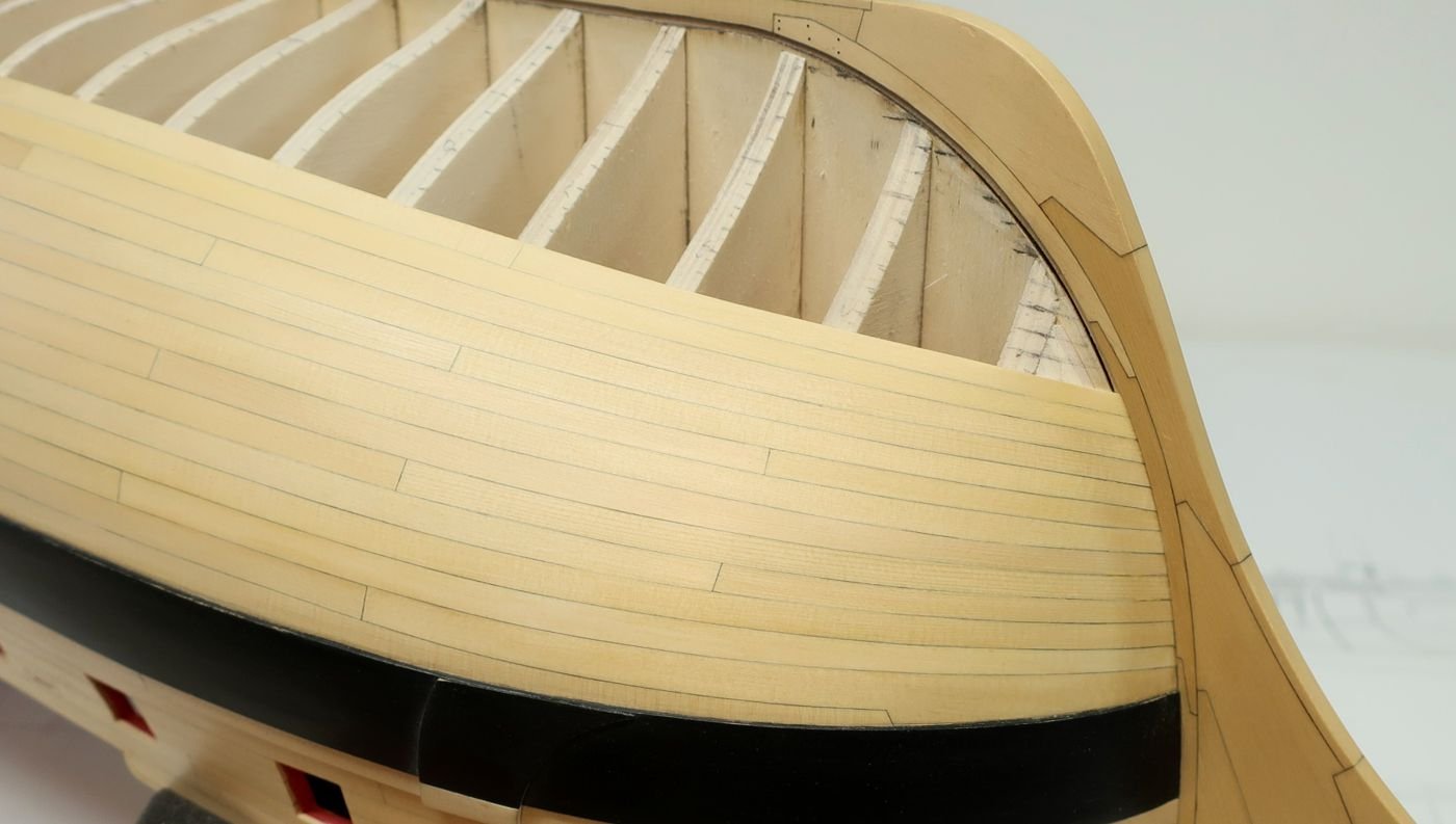
druxey Posted February 24, 2018 Share #32 Posted February 24, 2018 Yes, a large section of Colossus' starboard quarter side survived underwater, more or less intact, including the large quarter figure now being conserved. What is your comment or question on port stops, Archnav? paulsutcliffe, thibaultron and mtaylor 3 Be sure to sign up for an epic Nelson/Trafalgar project if you would like to see it made into a TV series http://trafalgar.tv Link to comment Share on other sites More sharing options...
Mark P Posted February 25, 2018 Share #33 Posted February 25, 2018 (edited) Good Morning Gentlemen; Thank you all for a very illuminating thread, which I have followed with great interest. I believe that Archnav's original question has been answered by a combination of earlier replies, as shown below. First I quote part of a post by Wayne, which is part of a very informative extract he posted from one of John Fincham's works. On 18/01/2016 at 11:55 AM, trippwj said: PORT STOPS (Page 226): are the ends and edges of the planks left round the ports, from 1 1/2 to 2 ¼ inches from the sides of the timbers and upper and lower parts of the sills, to receive the port lids and the half-ports. Followed some time later by Archnav's posting of an extract from Brian Lavery's AOS book on Bellona. On 18/04/2016 at 4:44 PM, archnav said: Hello, here is an interresting drawing from Brian Lavery - 74-gun ship BELLONA More and more confusing The description from Fincham, quoted by Wayne, seems to me to fit perfectly with the illustration included in Archnav's post showing the Bellona's ports. Taken together, the two are clear in their meaning. The port stops are formed by stopping the side planking slightly short of the actual port opening in the timbers, with the greatest width of exposed frame timber left at the bottom. This immediately creates a rebate, which will provide a good seal, and is easy to make. The rebate in the ship's side is thereby formed without any additional work being required to produce it. Likewise, the corresponding rebate in the lid is formed by the inner planking (lining) of the port lid being narrower than the outer layer of the lid's planking. Again, no need to perform any extra task to create a rebate. The ship's futtocks or toptimbers, and the port cills, are then left exposed to form the sides of the opening, and not covered in any way with any timber. The ship is planked; the port lid is made; and the two are put together when the lid is hung. Job done! At no part of the process is any extra planking fixed to the sides of the opening to form a stop. If this was to be done, it would open up a real can of worms: is the regulation size of the ports, listed in so many Naval documents, to be taken to refer to the port size before these additional timbers are fixed, or after? All the best, Mark P Edited February 25, 2018 by Mark P archnav, druxey, Kris Avonts and 2 others 5 Previously built models (long ago, aged 18-25ish) POB construction. 32 gun frigate, scratch-built sailing model, Underhill plans. 2 masted topsail schooner, Underhill plans. Started at around that time, but unfinished: 74 gun ship 'Bellona' NMM plans. POB On the drawing board: POF model of Royal Caroline 1749, part-planked with interior details. My own plans, based on Admiralty draughts and archival research. Always on the go: Research into Royal Navy sailing warship design, construction and use, from Tudor times to 1790. Member of NRG, SNR, NRS, SMS Link to comment Share on other sites More sharing options...
Mark P Posted February 25, 2018 Share #34 Posted February 25, 2018 Thank you Archnav for the link to the Colossus' wreck excavation reports. The stern carving has been mentioned on this site before (which was the first I knew of it) It has now been conserved (by the Mary Rose Trust) and is on display, at Tresco on the Scillies, I believe. However, the wreck excavation reports mentioned by Archnav are most interesting. I have not looked at them all, but the 2012 investigation and monitoring report deals in part with the excavation of a gunport. This is featured around page 32-38, and has some interesting items. The sections through this show the outer planking stopping short of the port cills, to leave a rebate. Of further interest is the presence of a standard knee in the excavated section. Another is reported from an earlier, adjacent, excavation, and the report concludes that they were present between each gun port. As these are not always shown on models, there has been some previous discussion as to whether or not these were still in use in the final decades of the 18th century. Their presence on a ship launched in 1787 shows that at that time they still were. Also of interest is the fact that the standard is made up of 3 separate pieces of timber. Many timber sizes are given, which is of interest also. Thanks again, Archnav. All the best, Mark P druxey, mtaylor, archnav and 1 other 4 Previously built models (long ago, aged 18-25ish) POB construction. 32 gun frigate, scratch-built sailing model, Underhill plans. 2 masted topsail schooner, Underhill plans. Started at around that time, but unfinished: 74 gun ship 'Bellona' NMM plans. POB On the drawing board: POF model of Royal Caroline 1749, part-planked with interior details. My own plans, based on Admiralty draughts and archival research. Always on the go: Research into Royal Navy sailing warship design, construction and use, from Tudor times to 1790. Member of NRG, SNR, NRS, SMS Link to comment Share on other sites More sharing options...
archnav Posted February 26, 2018 Author Share #35 Posted February 26, 2018 On 24.2.2018 at 2:16 PM, druxey said: Yes, a large section of Colossus' starboard quarter side survived underwater, more or less intact, including the large quarter figure now being conserved. What is your comment or question on port stops, Archnav? Hi druxey, looking at the sketches made by the excavation crew, the port side is the one which is visible, I think... What the "port stops" are, is now very clear, thank you all for your comments. But by looking at the ONE gunport of the wreck that is visible so clear and the sketches made of, there are two new structural parts belonging to this port, that are not mentioned in any of the published works, journal articles or forum posts, I believe. 1) A clearly visible, photographed, measured and drawn, strong piece of timber, nearly square, as broad as the port itself, and seen from above: with long radius rounded edges. It was fastened with an iron bolt in it`s middle to the ceiling of the ships side, beneth the port sill. It is documented as a: "stop beam" for the carriage of the gun on the gun deck. No port of the upper deck has a similiar timber fixed there, so it is possible, that it worked as a "Safety timber" for the movement af the carriages of the heavier guns !? Looking at the dimensions, it fits with the measurement given by Steel (3 - 1/2 "). If this is the measurement for the rebate at the outside of the port, it is 1 1/4 " lesser than given by Fincham ! ??? David Steel says: "not less than 3 1/2 " !!! for this rebate ??? The measurement of the rebate of Colossus fits more with those, given by Fincham ! 2) Also visible at the lower, inner end of the ports sides (frames), are two small vertical pieces of wood, looking to be a "part" of the frames side, forming a "slot" for the boards of "half ports" or maybe "washboards" when the ports are opened at sea for airing. Jean Boudriot made some sketches, showing how the french used a nearly similar construction on their seventy-four gun ships. Possible, that in english ships it was easier to let a thin board slide into such a slot, so no further fixation is needed ? The french used a combination of small ringbolts and hooks, to pull the board back and fix it. No upper port has a similar fitting, only this gun deck port, lying nearer to the waterline. There are some other findings on the wreckside that give room for speculations. A deadeye for rigging lower shrouds, which has a much greater diameter as for a seventy-four gun ship of war was used....bigger than those for 110-gun ships in the RN. ! ??? ...confusing Next, I will post some of the photographs and sketches made by the CISMAS team. Thank you Mark P for your comments ! mtaylor 1 All the best, Tom (sapere aude) Link to comment Share on other sites More sharing options...
druxey Posted February 26, 2018 Share #36 Posted February 26, 2018 Perhaps 'stop beam' is a misleading term. Perhaps 'bumper' or 'cushion' might better distinguish it from confusion with a port stop. mtaylor and archnav 2 Be sure to sign up for an epic Nelson/Trafalgar project if you would like to see it made into a TV series http://trafalgar.tv Link to comment Share on other sites More sharing options...
archnav Posted February 26, 2018 Author Share #37 Posted February 26, 2018 14 minutes ago, druxey said: Perhaps 'stop beam' is a misleading term. Perhaps 'bumper' or 'cushion' might better distinguish it from confusion with a port stop. Yes druxey, that`s a possibility, but there is still the question what Steel meant. The rebate for the port lid or this piece of timber...hmm Looking at the dimensions given by the excavation team for the rebate and that given by Steel, it can`t match ! Not less than: 3 1/2 " (74-gun ship) Much wider than the dimensions given by Fincham and found here ont the port of the Colossus - so was Steel wrong ? The point of discussion here is the declaration: NOT LESS THAN...that means a minimum, so rather more ! Even more misleading, right ? On the other hand, he gives this dimension explicit along with the dimensions for the PORT LID - not in the chapter of the PORTS !? ...and as I mentioned, this "bumper" (Stop Beam) matches in his square dimensions to the 3 1/2" given by Steel..............so am I completely wrong ? Don`t misunderstand me guys, I don`t insist on my theory......I`m just confused about the dimensions of the rebate for the lid that differ so much. Your statement makes sence druxey, and I am with you that these dimensions belong to the port lid only, because they are given explicit in this chapter. The separate chapter of the gunports shows no mention of such a piece of timber for to stop the gun carriage, at all ! The fallowing excerpts of pictures and sketches from the excavation reports, are accompanied by colored remarks for better understanding of the things discussed. mtaylor and jud 2 All the best, Tom (sapere aude) Link to comment Share on other sites More sharing options...
archnav Posted February 26, 2018 Author Share #38 Posted February 26, 2018 Please pay attention that the pictures of the port stand upside down ! First picture shows the gun deck port This picture shows the port from a lower angle...the "Stop Beam" or "bumper" is clearly visible Next is the left side of the port which is the side of one of the frames - look at these thin pieces of wood, forming a slot for a washboard ? Next comes the sketch of the port seen from above like in the first picture Here you can see the much smaller rebates for the (missing) port lid - this don`t matches with Steel`s dimensions ! Last picture shows the port as once being intact - note again the small rebates for the lid and the fact, that the ship was built without any waterway ! I hope, that this discussion here will go on. Thanks guys for your help to find some conclusive answers - thank you really very much druxey, ulrich, trippwj and 3 others 6 All the best, Tom (sapere aude) Link to comment Share on other sites More sharing options...
paulsutcliffe Posted February 26, 2018 Share #39 Posted February 26, 2018 It appears that the stops are for the guns maybe instead of the waterway which the front wheels would normally run up to, to stop the gun running into the bulwark The stops you pointed to for the gun ports would presumably be the same thickness as the ports, so looks smooth from the outside Regards Paul mtaylor and druxey 2 The clerk of the cheque's yacht of sheerness Current build HMS Sirius (1797) 1:48 scratch POF from NMM plans HMS Winchelsea by chuck 1:48 Cutter cheerful by chuck 1:48 Previous builds- Elidir - Thames steam barge Cutty Sark-Billings boats Wasa - billings boats Among others 😁 Link to comment Share on other sites More sharing options...
Mark P Posted February 26, 2018 Share #40 Posted February 26, 2018 (edited) Hi Archnav; The dimensions of the 'stop beam' in the excavation report bear little resemblance to anything quoted by Steel or Fincham. The excavator lists this timber as being 1.4m long x 160mm x 260mm at its widest (55" x 6 1/2" x 10"widest) This is a very substantial piece of wood. Its curved inner face is conjectured to have been designed to make traversing the gun easier. This cannot be any connection with anything referred to by Steel under the heading 'Port stops'. I can think of no obvious reason for the differences between Fincham and Steel, except perhaps for different yards working to different practices (or changing customs over time) The 3 1/2 " minimum may be a typo, or it may not. Can you post the relevant part of the text from Steel. I cannot find it in my (digital) copy. Separately, and rather worryingly, and referring to the 'Colossus' report: although the drawn sections show no sign of the waterway, the photographs do appear to show one! The side view of the standard (fig 30 in the report) quite clearly shows a shaped timber running along in the angle between the deck planks and the side planks. The bottom inner corner of the standard has been cut away to clear this and leave a gap, which was to allow water to flow through so that it could reach the scuppers. In addition, in the photos you have posted fig 28 shows this same length of timber, visible below your words 'slot has fallen apart'. By the way, what programme do you use to insert the pictures here. I tried, but it was beyond my skills. I need to educate myself! Concerning the piece of timber which presumably slotted into the small battens at the bottom half of the gunport, this may well have functioned to stop water entering when there was a bit of a sea running. But bearing in mind that the seamen messed at a board table set up with one end fixed into the gunport, it would also have served to prevent items on the table from sliding through the port if it was open, and making a quick descent into the depths. Two functions from one piece of wood. It would appear to be that the excavators have missed a piece of timber. Maybe, as the drawings were made on land, and possibly not by the person who was underwater, the illustrator may have had a pre-conceived idea of how the deck planks meet the sides of a ship like Colossus. All the best, Mark P Edited February 26, 2018 by Mark P druxey, mtaylor, paulsutcliffe and 1 other 4 Previously built models (long ago, aged 18-25ish) POB construction. 32 gun frigate, scratch-built sailing model, Underhill plans. 2 masted topsail schooner, Underhill plans. Started at around that time, but unfinished: 74 gun ship 'Bellona' NMM plans. POB On the drawing board: POF model of Royal Caroline 1749, part-planked with interior details. My own plans, based on Admiralty draughts and archival research. Always on the go: Research into Royal Navy sailing warship design, construction and use, from Tudor times to 1790. Member of NRG, SNR, NRS, SMS Link to comment Share on other sites More sharing options...
druxey Posted February 26, 2018 Share #41 Posted February 26, 2018 Here's my (limited) understanding. The port stops mentioned in Steel (Folio XXV) are 3 1/2" thick. As the measurements given of the stops for other large ships range from 3 1/2" to 3", I doubt that it is a misprint. A substantial stop would make sense for watertightness in rough seas. After all, the freeboard was only about 6' 0". But to me, the interesting part are the battens on each side of the port. I agree that they must be for boards to slot into. Steel's tables (Folio XXVI) call for Well seasoned linings fitted into the stops, thick 1 1/8" (for a 74 gun ship). I'd long wondered what 'linings' were. Those must be the 'washboards' in this discussion! paulsutcliffe, archnav, trippwj and 1 other 4 Be sure to sign up for an epic Nelson/Trafalgar project if you would like to see it made into a TV series http://trafalgar.tv Link to comment Share on other sites More sharing options...
jud Posted February 27, 2018 Share #42 Posted February 27, 2018 (edited) I have been looking for these stop beams for a long time now. Having experience at sea and with guns and how it all works together, I have been very discomforted with no stop beams or a similar provisions being in place for the gun carriages to rest against and allow sideways aiming through the ports. Poorly received when asking about such bumpers, Unable to turn the focus from the configuration of the Gun Port fitting, to the Gun and its need to prevent damage to the port, Bulwark or the often noted Waterway. This stop or Bumper has nothing to do with the Gun Port Lid or it fitting into the sides of the ship, but that Bumper has a lot to do with protecting all of it, it probably was so common it was hidden in plain sight and not mentioned. Takes an 1798 wreck to bring common sense back where it can be seen and where protection from damage to the ship is so clearly needed. Gunner at 13, had to roll my own. Edited February 27, 2018 by jud archnav 1 Link to comment Share on other sites More sharing options...
mtaylor Posted February 27, 2018 Share #43 Posted February 27, 2018 Just speculation, but is it possible that this is something that was a "one of"? A test maybe or prototype? We know that while the "establishments" were the intended specs and methods that often the designers, the Navy, even the ship's compliment made changes for practical reasons. archnav 1 Mark "The shipwright is slow, but the wood is patient." - me Current Build: Past Builds: La Belle Poule 1765 - French Frigate from ANCRE plans - ON HOLD Triton Cross-Section NRG Hallf Hull Planking Kit HMS Sphinx 1775 - Vanguard Models - 1:64 Non-Ship Model: On hold, maybe forever: CH-53 Sikorsky - 1:48 - Revell - Completed Licorne - 1755 from Hahn Plans (Scratch) Version 2.0 (Abandoned) Link to comment Share on other sites More sharing options...
jud Posted February 27, 2018 Share #44 Posted February 27, 2018 (edited) Have seen the references of the bottom boards of gun carriages extended forward and convex to the gun, so they could rest against the sides and keep the wheels free of the side allowing the training of the gun to be smooth, even then I would expect a sacrificial rub block to be mounted on the bulwarks. Those training tackles would be problematic if the gun needed to be trained forward or back with the gun resting on its flat face then bouncing around one wheel as the gun was pointed. The idea of the waterways holding the wheels clear of the bulwarks when training it around using tackles is against the laws of physics, the wheel will run up the slope or jump the curb running it's sharp corner into the bulwarks and causing damage at the contact point. No, the gun needs to be stopped before the wheels come in contact with the sides and that stop must allow for the training of the gun around without jamming a wheel into the bulwarks. If the gun was restricted so both front wheels and it's carriage face contact the bulwarks at the same time a stop or buffer would also be needed, but they are required to be aimed, probably through a 30° arc. The buffer makes sense and fulfills a missing link in gun handling through gun ports. Would expect the contacting surfaces to be lined with harness leather. Edited February 27, 2018 by jud mtaylor and archnav 2 Link to comment Share on other sites More sharing options...
archnav Posted February 27, 2018 Author Share #45 Posted February 27, 2018 (edited) Hi guys, and thanks very much for your lively participation ! I will answer you questions in the sequence they were posted. 1) Mark P I agree with you, that 3 1/2" for such a substancial piece of timber must be wrong. Really looks to be the wideness of the rebates flat surface for the port lid to fit onto (not into) the gun port. To fit into the port, the thin boards of lining were nailed vertically onto the timbers of the lid. Maybe the term: "stops", in context with the lid, means the outside planking to "stop off the port", so the missing "f" in the word "of" in Steel, caused this problem - this is my conclusion. Here is the section of the Port Lid for the gundeck out of David Steel`s: Naval Architecture 1805, you`ve wished to see: You are also right with the waterway that can be seen in two of the divers photographs but may be forgotten to be drawn in the sketches by the draftsman. Thank`s for your attention and eagle eye - Many eyes see many more details ! Were the mess tables not placed between the gun ports ? I have in mind they were... Edited February 27, 2018 by archnav mtaylor 1 All the best, Tom (sapere aude) Link to comment Share on other sites More sharing options...
archnav Posted February 27, 2018 Author Share #46 Posted February 27, 2018 (edited) 2) druxey Steel does`nt speak of "thickness" - the most probable explanation is, that this "measurement" gives the way, the outside planks "have to stop" off (before) the port, that the lid has a rest on this rebate. I believe, that this is the right explanation. A substantial piece of wood to keep the ports watertight as you mentioned, may be seperately stowed and used as the ones, that the french used: a strong timber, placed horizontely across the width of the port, fixed with kind of rigging through the inner hinge rings of the lid. The "linings" you referred to, not meant the thin boards that could be used as "washboards" at sea, by letting them slip down between this wooden battens. These are just the boards, nailed vertically on the inner face of the lid (as I have discribed earlier), forming a kind of "frame with a rebate" within the lid`s outer ends. Here Steel gives a real "thickness" of 1 1/4" ! The "washboards" I think, were thin wooden boards, put into the "slot" formed by the (visible) two small battens, to give some protection - a freebord of only about 6 feet as you mentioned - but only in a calm sea Edited February 27, 2018 by archnav mtaylor 1 All the best, Tom (sapere aude) Link to comment Share on other sites More sharing options...
archnav Posted February 27, 2018 Author Share #47 Posted February 27, 2018 (edited) 6 hours ago, jud said: "I have been looking for these stop beams for a long time now. Having experience at sea and with guns and how it all works together, I have been very discomforted with no stop beams or a similar provisions being in place for the gun carriages to rest against and allow sideways aiming through the ports. Poorly received when asking about such bumpers, Unable to turn the focus from the configuration of the Gun Port fitting, to the Gun and its need to prevent damage to the port, Bulwark or the often noted Waterway. This stop or Bumper has nothing to do with the Gun Port Lid or it fitting into the sides of the ship, but that Bumper has a lot to do with protecting all of it, it probably was so common it was hidden in plain sight and not mentioned. Takes an 1798 wreck to bring common sense back where it can be seen and where protection from damage to the ship is so clearly needed." I am with you jud - thanks for this discription of the need for such a bumper ! Edited February 27, 2018 by archnav mtaylor and jud 2 All the best, Tom (sapere aude) Link to comment Share on other sites More sharing options...
archnav Posted February 27, 2018 Author Share #48 Posted February 27, 2018 4 hours ago, mtaylor said: Just speculation, but is it possible that this is something that was a "one of"? A test maybe or prototype? We know that while the "establishments" were the intended specs and methods that often the designers, the Navy, even the ship's compliment made changes for practical reasons. Yes Mark, I think you are right. Maybe this was a tryout to reduce damage or to protect the waterways. On the other hand, what if this kind of protection was jet "standard" for the heaviest guns at that time ? Later (in the early 19th century), those "bumpers" or "forward protections" were built within the front of the sides of the carriages, some kind of a "nose" projecting forward. Doesn`t remember by now where I have seen this example....trying to find it again. Caruana ? Must take a look druxey, mtaylor and jud 3 All the best, Tom (sapere aude) Link to comment Share on other sites More sharing options...
archnav Posted February 27, 2018 Author Share #49 Posted February 27, 2018 (edited) Again to Mark P: You asked me what program I use to post the pictures - the same as all users here...it`s part of the "reply to this topic" mask. Using the button "choose files" at the lower left end of the mask, opens my computer files and there I am able to mark the jpeg-file I want to post. The text Editior loads the picture and I can put it directly into the text mask by "drag and drop". I hope this is the correct answer to your question. Or did you mean the way I cut out the pics from the PDF-files and copied arrows and text into the pics ? Edited February 27, 2018 by archnav mtaylor and Mark P 2 All the best, Tom (sapere aude) Link to comment Share on other sites More sharing options...
druxey Posted February 27, 2018 Share #50 Posted February 27, 2018 So, if I understand correctly Archnav, you think that the port lid thickness was 3 1/2" and the inner layer of the lid was 1 1/8" thick? Diving into Caruana, he refers to the 1795 pattern carriage as having projecting 'horns' from the front of the brackets (side pieces) at the height of the lower sill (Volume II, page 379 et seq). These acted as a kind of bumper. The official title was a "breast ended preventer cleated" carriage. One may then presume that the bumper/stop beam/preventer piece seen across the lower edge of Colossus' port is a fore-runner of this later development. archnav, jud, Mark P and 2 others 5 Be sure to sign up for an epic Nelson/Trafalgar project if you would like to see it made into a TV series http://trafalgar.tv Link to comment Share on other sites More sharing options...
archnav Posted February 27, 2018 Author Share #51 Posted February 27, 2018 Hi druxey, I think you misunderstood me. I didn`t mean the thickness of the port lid timbers, these have the thickness of the outside planking. No, what I meant is the distance of the end of the outside planking to the port on the surface of the frame, and the same distance from the topside of the planking beneth the port on the surface of the lower sill. This is the small frame for the port lid to rest on and this is the measurement given by Steel. The lining, which is nailed on the inside of the lid, then fits into the port itself, so that this assembly forms the complete port lid, building a rabbet at it`s corners. This lining is given by Steel with: 1 1/4" thickness. Thanks for the information of the carriage in Caruana - this "horn" is what I meant with "nose". I am with you in the opinion, that the "bumper" in the wreck of Colossus maybe is a kind of fore-runner. Possible, that this was practice in french 74-gun ships of that time and the Navy copied this to make a try-out ? Maybe this was standard in the RN but not mentioned as a part of the fitting of the hull ? So not mentioned by Steel ? Maybe in a book about gun handling of that time ? All in all a very interesting find on this wrecksite and in the case of handling a heavy gun in it`s carriage, a logical fitting I think ! mtaylor, druxey and Mark P 3 All the best, Tom (sapere aude) Link to comment Share on other sites More sharing options...
archnav Posted February 27, 2018 Author Share #52 Posted February 27, 2018 In the case of fasten a port lid tight to it`s gun port, a friend of mine sent me a sketch out of a book he can`t remember. It shows a "half-port board" (with it`s circular cut-out in the middle), that is fixed with wedged hooks to this board, hung into the ringbolts of the lid. Take a look...maybe one of you can identify this drawing ? mtaylor, Mark P, jud and 1 other 4 All the best, Tom (sapere aude) Link to comment Share on other sites More sharing options...
druxey Posted February 27, 2018 Share #53 Posted February 27, 2018 Liebe Archnav, Perhaps a small sketch will help me understand better what you mean by "the distance of the end of the outside planking to the port on the surface of the frame, and the same distance from the topside of the planking beneath the port on the surface of the lower sill." I'm glad we agree on the 'bumper' issue! Similar fittings, but with a central hole, were used with 'inside principle' carronade mounts for the traverse pins. Mit grusse mtaylor 1 Be sure to sign up for an epic Nelson/Trafalgar project if you would like to see it made into a TV series http://trafalgar.tv Link to comment Share on other sites More sharing options...
druxey Posted February 27, 2018 Share #54 Posted February 27, 2018 I just saw the sketch you posted: I've never seen this sketch before. Interesting! mtaylor and Mark P 2 Be sure to sign up for an epic Nelson/Trafalgar project if you would like to see it made into a TV series http://trafalgar.tv Link to comment Share on other sites More sharing options...
jud Posted February 27, 2018 Share #55 Posted February 27, 2018 Looks like a secure and quick way to secure a lid closed with a moderate amount of closing pressure. Such a setup would allow some oakum to be placed around the sill, port closed against it and the board, hooks and wedges taped into place, making a seal from the oakum that would not cause binding on lid or port as sealing the sides might do. jud archnav, Mark P, mtaylor and 1 other 4 Link to comment Share on other sites More sharing options...
Mark P Posted February 27, 2018 Share #56 Posted February 27, 2018 Hi again Archnav; Firstly, you are of course quite right: mess tables were set up between the gunports, not at them. There was a thumping great 32pdr cannon in the way! Silly me. Secondly, I believe that the dimension given in Steel refers, as you say, to the distance by which the outer planking of the port lid overlaps the exposed frame timbers, which are left uncovered around the gunport when the ship's planking is stopped short. Thirdly, you are correct in your thoughts: it is indeed the method you use to extract part of the pdf and then write all over the extracted part which I am unable to master. A brief pointer would be very welcome. Thank you for posting the further pictures. In case anyone was wondering, the one showing the standard has the deck planking vertically to the right, and the side planking along the bottom. All the best, Mark P archnav, druxey and mtaylor 3 Previously built models (long ago, aged 18-25ish) POB construction. 32 gun frigate, scratch-built sailing model, Underhill plans. 2 masted topsail schooner, Underhill plans. Started at around that time, but unfinished: 74 gun ship 'Bellona' NMM plans. POB On the drawing board: POF model of Royal Caroline 1749, part-planked with interior details. My own plans, based on Admiralty draughts and archival research. Always on the go: Research into Royal Navy sailing warship design, construction and use, from Tudor times to 1790. Member of NRG, SNR, NRS, SMS Link to comment Share on other sites More sharing options...
archnav Posted February 27, 2018 Author Share #57 Posted February 27, 2018 (edited) Hi druxey, here is a small sketch you asked for - I hope this is of help for you - If not, i`ll make a better one tomorrow Good night everybody - it`s 8 pm here in Bavaria/Germany and I´m going to watch Snooker on TV now Edited February 27, 2018 by archnav druxey, Mark P and mtaylor 3 All the best, Tom (sapere aude) Link to comment Share on other sites More sharing options...
druxey Posted February 27, 2018 Share #58 Posted February 27, 2018 That is exactly as I thought and tried to say about the 3 1/2" measurement! Language...the greatest barrier to communication! Thank you, Archnav. It was what the lining was that confused me before. mtaylor and archnav 2 Be sure to sign up for an epic Nelson/Trafalgar project if you would like to see it made into a TV series http://trafalgar.tv Link to comment Share on other sites More sharing options...
mtaylor Posted February 27, 2018 Share #59 Posted February 27, 2018 I remember where I've come across the the "curved wood" on the port bottom. Some French ships were outfitted with this for the reasons Jud gave above. Often curved towards the gun for the carriage to pivot against when training the weapon. We have to remember that the Establishments were just periodic upgrades to the document and much happened in the shipyards that never made the Establishment for one reason or another. That port lid, again Jud may be right. archnav, druxey and jud 3 Mark "The shipwright is slow, but the wood is patient." - me Current Build: Past Builds: La Belle Poule 1765 - French Frigate from ANCRE plans - ON HOLD Triton Cross-Section NRG Hallf Hull Planking Kit HMS Sphinx 1775 - Vanguard Models - 1:64 Non-Ship Model: On hold, maybe forever: CH-53 Sikorsky - 1:48 - Revell - Completed Licorne - 1755 from Hahn Plans (Scratch) Version 2.0 (Abandoned) Link to comment Share on other sites More sharing options...
trippwj Posted February 27, 2018 Share #60 Posted February 27, 2018 This topic remains very informative! I had not delved into the excavation and survey reports on the Colossus before. They are quite interesting. Of particular note concerning the "stop beam" (note that this is a term the research team coined) is the following analysis from the 2012 Monitoring and Investigation Report available here (page 38): http://www.cismas.org.uk/downloads.php "Just below the gun port a curved timber beam was fastened to the side of the hull, over the inner hull planking (figs 24, 25 & 31). This timber has been assigned the name ‘stop beam’ and its likely function was for the gun carriage to bump against when the gun was pulled up into the firing position – rather than bumping against the inner hull planking. I have been unable to find any concordances for this structural element in any of the literature on ships of the period (or indeed on any sailing vessels). However, a similar wooden beam is known in 19th century terrestrial gun emplacements where it is called a hurter. The stated function of the hurter was to protect the parapet from the wheels of the gun carriage (OED). The stop beam is 1.40m long, 0.16m wide and 0.26m thick at its widest point. The surface of the beam is curved, presumably to facilitate aiming of the gun forward or astern of the beam. The stop beam is fastened to the hull using iron fastenings and trenails. On the underside of this beam (now facing north) were a number of incised lines, one of which consists of three parallel lines, resembling a Roman numeral ‘III’ (fig 32). These may represent builder’s marks – and would have been very difficult to see or access when the ship was upright. Incidentally, this is the third MGD port on the starboard side counting from the stern. The function of this piece of wood was presumably to protect the side of the ship from the impact of the gun carriage when pulled up into the firing position (fig 31). Whether stop beams are a peculiarity of Colossus or merely absent from the literature is not at this stage known – but I suspect the former case is more likely." On a related note, I do not believe that, given the level of attention shown to documenting the survey, they ommitted the waterway, but rather it was not there. Note the scupper that was located at deck level, which would have been covered were there a waterway (note - down is up n these photographs and the sketch. That is, the deck is at the top and the upper deck is at the bottom). jud, mtaylor, paulsutcliffe and 2 others 5 WayneNeither should a ship rely on one small anchor, nor should life rest on a single hope.Epictetus Link to comment Share on other sites More sharing options...


Recommended Posts