catopower Posted August 7, 2017 Share #1 Posted August 7, 2017 I thought I'd start a new blog here to show what I have been working on in between my paper model "distraction" projects. This too is something of a distraction project, but it's also part of my on-going study of Japanese traditional watercraft. To date, the Japanese boat models I've done are mostly kits, mostly Edo period (1603-1860), and mostly small boats. This model differs in a lot of ways from the others in that it is from the Kamakura period (1185-1333), is a scratch build, and is a larger boat, nearly 100 feet long. The boat type is old enough, or perhaps obscure enough, that there is no specific term to identify it other than as a Kamakura period large sea boat, or in Japanese, Kamakura jidai no dai umi-bune. Something of a long name, so I'll just refer to it as an Umibune, since the term doesn't really seem to used in other contexts. I got interested in the Umibune (that's oo-me-boo-nay) partly because there are few build plans of Japanese watercraft to be found anywhere. The Japanese don't have a history of recording measurements or detailed drawings of their work. Instead these boats were built by craftsmen who kept their techniques secret and passed their work on to their apprentices. So, the only details we really have are from those who have studied relics, paintings, and other boat designs. In this case, my primary source of information is from the late Professor Kenji Ishii who wrote a few books on the subject, and is pretty well considered the "Father of Japanese Boats". Last year, I located the "bible" of traditional Japanese boat research, Professor Ishii's book, published in 1983. The book has been out of print, though it seems to have been supplanted by a two volume set of smaller books that essentially contain the same information, and is called the Illustrated History of Japanese Traditional Boats. It is written entirely in Japanese, which makes research very challenging – I can't really read much Japanese. But, there is the technology and the determination to overcome such obstacles. In addition, there is a website of the Nippon Foundation Library, which hosts online articles on many subjects. This is actually where I first learned about the Umibune. The site showed a small image of a museum model of an Umibune as part of a small chapter on these boats and their construction. It's in Japanese, but here's a link to the site: https://nippon.zaidan.info/seikabutsu/2000/00200/contents/057.htm While this was an interesting find, at the time I ran across it, it was just one of many subjects I ran across in my research. The fact that it was a boat of the Kamakura period kind of put it out of my view, as I was focussing so much on the Edo period, which took place 300 to 600 years later. It was hard enough to study Edo period boats, and I knew even less about the Kamakura period, so I pretty well set the subject aside. It wasn't until I got a copy of Professor Ishii's work that I started taking a more serious interest. You see, Japanese boats are so different from their Western counterparts, that the simple drawings that I could find were mostly inadequate (or perhaps I was more inadequate) for creating a reasonably accurate model. But, Professor Ishii's book included a 3-view diagram of this particular boat, which was more detail available than for most subjects. Now, if the subject were of a more complex design, this diagram might prove next to worthless for model building purposes. But, I realized that the characteristics of this particular boat design allow me to use the 3-view drawing as a build plan. Now I've actually gotten pretty far along on this model, but I thought I'd take the opportunity to document the work here as best I can, so anyone interested can get an idea of what's been going on. If it inspires or connects me with others interested in Japanese traditional watercraft, so much the better. RichardG, thibaultron, Landrotten Highlander and 14 others 17 Quote Clare Hess He's a -> "HE" Link to comment Share on other sites More sharing options...
cog Posted August 7, 2017 Share #2 Posted August 7, 2017 Interesting choice Clare-san. You should know as no one else at MSW that Japanese don't use drawings as used in western building, and therefore drawings are most certainly inadequate, but for Douglas Brooks' drawings. I wonder, however, if he would have a drawing for this boat!!! I'll be following with more than a casual interest. Cheers popeye the sailor, mtaylor, Canute and 1 other 4 Quote Carl "Desperate affairs require desperate measures." Lord Nelson Search and you might find a log ... Link to comment Share on other sites More sharing options...
SawdustDave Posted August 7, 2017 Share #3 Posted August 7, 2017 Hi again Clare. Been a while since I've seen you around. This looks really interesting.... and challenging, so I'm checking in. Dave Canute, catopower, mtaylor and 1 other 4 Quote Sawdust Dave - Current build - USS Constitution 1:60th (scratch).... Visit my blog site - All previous builds.... http://davesmodelships.blogspot.com Link to comment Share on other sites More sharing options...
catopower Posted August 7, 2017 Author Share #4 Posted August 7, 2017 (edited) Hi Carl, Douglas Brooks focusses on preserving the information of this last generation of traditional wooden boatbuilders, so it's not the kind of thing he has much information about. He did, however, provide me with a couple nice photos of a museum model that appears to be the same model as on the Nippon Foundation website that I mentioned. The model was part of a display that was set up at the carpentry tools museum in Kobe, Japan, in the Spring last year, where he had a boatbuilding project that people could watch live. I recommend visiting his blog, if you haven't already: http://blog.douglasbrooksboatbuilding.com/2016/03/takenaka-carpentry-tools-museum.html It doesn't have anything to do with my model, but his work is fascinating and very important. Hi Dave, I'll try to keep it interesting – Good to see you around! Edited August 7, 2017 by catopower druxey, Ryland Craze, mtaylor and 2 others 5 Quote Clare Hess He's a -> "HE" Link to comment Share on other sites More sharing options...
Canute Posted August 7, 2017 Share #5 Posted August 7, 2017 Clare, looks interesting. I'll pull up a seat and follow along, too. mtaylor, catopower and popeye the sailor 3 Quote Ken Started: MS Bounty Longboat, On Hold: Heinkel USS Choctaw paper Down the road: Shipyard HMC Alert 1/96 paper, Mamoli Constitution Cross, MS USN Picket Boat #1 Scratchbuild: Echo Cross Section Member Nautical Research Guild Link to comment Share on other sites More sharing options...
Jim Lad Posted August 8, 2017 Share #6 Posted August 8, 2017 Looks like your Japanese is going to improve rapidly, mate! John mtaylor, Canute, catopower and 1 other 4 Quote Link to comment Share on other sites More sharing options...
catopower Posted August 8, 2017 Author Share #7 Posted August 8, 2017 Hi John, you'd think my Japanese would be improving with all this stuff. But, in actuality, it seems to be making me a more confused person... I HAVE, however, gotten quite proficient at scanning and clipping text and using Google Translate, and then sorting through the odd translations. It's a lot like tying ratlines. Don't think about it, it's a long process, you just do it one step at a time... druxey, andante, Ryland Craze and 4 others 7 Quote Clare Hess He's a -> "HE" Link to comment Share on other sites More sharing options...
Tim Murphy Posted August 8, 2017 Share #8 Posted August 8, 2017 Clare, read your new post on the Kamakura Boats. Look's like I will learn something more on the History of Japanese boats! Thank You, Tim Murphy mtaylor, popeye the sailor, Canute and 1 other 4 Quote Link to comment Share on other sites More sharing options...
catopower Posted August 8, 2017 Author Share #9 Posted August 8, 2017 (edited) Ken, Tim, I'm happy to have your company here. As I proceed, let me state for the record that I'm no expert on Japanese traditional boats, nor do I know much about Japanese history. I really just know bits and pieces, and spend a lot of time learning and relearning things. I'm interested in Japanese culture, being half Japanese myself, and spend a fair amount of time and energy making Japanese and Japanese related connections, like with Woody Joe, Douglas Brooks, Thermal Studio (the Tosa wasen kit), The Rope, etc. But, any Japanese ship modeler who has an interest in the subject of Japanese traditional boats, could surpass my knowledge in a heartbeat, just from their ready access to written information, museums, etc. Still, very few Japanese people have much of an interest in the details of things of this nature. I have managed to foster a friendship with a couple Japanese ship modelers. One of them has some knowledge of Japanese boats because he was helping someone outside the country with information on them, and has been helping me out over the past year or so. Only recently did he build what I believe is his first model of a Japanese traditional boat, the Tosa wasen kit from Thermal Studio. So, all of this is really to say that getting information can be very difficult, but if you're interested and have any questions, I'm happy to help in what ways I can. Edited August 8, 2017 by catopower Canute, mtaylor, druxey and 2 others 5 Quote Clare Hess He's a -> "HE" Link to comment Share on other sites More sharing options...
catopower Posted August 9, 2017 Author Share #10 Posted August 9, 2017 There’s a lot of history and background to discuss for the this model, but what’s a build log without the construction of the model itself? If you look at the line drawing I posted at the start, you’ll see that the hull has a semi-circular base to the hull. That’s because these boats were essentially dugouts. It is what Japanese scholars call a semi-structured type, or a junkozosen. It features a dugout log hull with reinforcing beams and the addition of hull planking to increase the ship’s seaworthiness and carrying capacity. You'll notice that the scale is labeled with and 尺 character, which is the symbol for shaku, the Japanese carpenter’s unit of measure, which is almost exactly equal to one foot. This shows our Umibune has a hull cross-section of about 9 feet. The log hull was probably made from the Japanese camphor tree, which is a type of evergreen that’s not particularly tall, but with a trunk that has been known to reach over 20 feet in diameter. A boat this large was built in sections, and the drawing suggests four sections, a shaped bow and stern section that is attached to two dugout log sections fastened end-to-end. I don’t have any information about how the logs were securely fastened end-to-end, but I did find an illustration in one of Professor Ishii's later books that suggests it’s not just a simple joint. Before I could start, I needed to choose the scale for this model. I’d love to have some consistency of scale between my Japanese boat models. But, my models are all over the place here. I have 1/10-scale for my Tosa wasen, 1/24 for the Woody Joe kits of the Hacchoro and Yakatabune, 1/72 for the Higaki Kaisen, 1/20 for the rice field boat, and so on. For small boats, I’m trying to try to stick to a common scale of 1/10, for medium-sized boats, 1/20-scale is okay, and maybe for the largest boats, I’ll shoot for 1/50-scale. For the Kamakura period Umibune, this makes the model just about 2 feet long, which should be a reasonable size for a model on the shelf. I set about scanning and resizing the drawings accordingly. Hull Construction The first issue I came across then, was whether or not I needed to carve out a hull to build this model. For the modeling of a smaller boat, it would certainly have been necessary. But, a boat this size would probably have had a planked deck. Looking at other, later Japanese boats, these planked decks were commonly flush with the transverse beams that you see in the cross section images. In the case of this hull, the planked deck would sit upon the edge of the dugout section of the hull. The same would be true at the bow and stern. This meant that it wasn’t necessary to carve out the hull, I just needed to built a round hull. Also, the main hull has the same cross section all the way down its length, making construction very simple. Since I didn’t have to actual carve out log-shaped pieces, I decided to cheat a bit, and build the model “Western-style.” That is, I made a series of semi-circular bulkheads, shaped to templates I made from the drawing. The bulkheads would be connected together by a single basswood strong-back that would run the length of the main hull. The illustration below shows the section of the strong-back as a broken-outline rectangle. The arrow show the placement of the beams and planks directly on top of the strong-back. I cut five bulkheads out of basswood. The bulkheads are all identical, so the spacing isn’t particularly relevant. I just spaced them out evenly. Now, with a bit more foresight, I would have added some kind of internal keel down the center, even in separate pieces, just so I could drill it for mounting posts. As it was, the bulkheads themselves were fine, but locating them after the hull is constructed adds some complexity to the task. Between the bulkheads, I put in a series of basswood strips that would help support the bulkheads, and would later give me something to drill into for mounting pins, though I probably should have used thicker strips for this reason. In any case, rather than planks, I covered the hull bottom with a single sheet of balsa, which I figured would be flexible enough to wrap around the curve of the bulkheads. This turned out fine, but did require a lot of care during construction, as the balsa crushes or mars easily. But, little dents are also fairly easy to repair as I later found. The ends of the hull were simply shaped basswood blocks. I traced the profiles onto the block, carved away the bulk of the excess wood, and then used the belt sander for the bulk of the shaping. Note that the shape of the ends differs very slightly between bow and stern, as the bow rises a bit more sharply. cog, Ryland Craze, Archi and 6 others 9 Quote Clare Hess He's a -> "HE" Link to comment Share on other sites More sharing options...
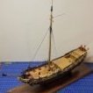
catopower Posted August 10, 2017 Author Share #11 Posted August 10, 2017 (edited) Here's another pic of the hull that I didn't post last time. My plan is to paint this portion of the hull black using Liquitex acrylics. Because the balsa sheet of the main hull is grainy and porous, I'm using a bit of wood conditioner on it first and giving it a light sanding. Deck planking will sit directly on top of this assembly, so you can see that there is no need for a carved out hull. Had this been a model of a smaller boat, I would have had to carve it out. The next step will be to add the trapezoidal-shaped platforms that will fit on top of the end sections of the hull at the bow and stern. These platforms look pretty straight forward and will have to be pieced together from planks, though it took some study of the stern platform (right side of drawing) to understand what's going on there. Below is a breakdown of some of the elements of that stern platform. Sorry the image is a little fuzzy as I had to blow it up to fit the text in there. And finally, here's an image of a museum model that was on display at the tool museum in Kobe while Douglas Brooks was building a boat there. The image is courtesy of Douglas Brooks. You can see a lot of details in this model that are hard to see in the 3-view drawing. More on the end platforms next time. Edit: In the background of this last photo, you can see two other models. In the far background is an Atakebune (ah-ta-kay-boo-nay), which was a warship from the Warring States period, roughly from the mid-15th century through the end of the 17th century. These were the largest of the Japanese warships. Something akin to their battleships. They were big, lumbering ships with a small castle-like structure mounted atop. The other vessel in the mid background on the left is a Kawagozabune (kah-wa-go-za-boo-nay), something of a highly ornate riverboat/yacht used by nobility as a symbol of their prowess. This would have been seen primarily on the rivers connecting Osaka and Kyoto. I'm not sure how far back these yachts date back. I'm guessing that this one in particular is probably from the Tokugawa period (1603-1868) as the period was peaceful enough that this type of boat could be safely used, and the hull is of a built-up, structured hull. But, there were similar types of river transports, not so well decorated, that had hulls similar to my Umibune. Edited August 10, 2017 by catopower Additional info on other boats in last photo druxey, IgorSky, Siegfried and 9 others 12 Quote Clare Hess He's a -> "HE" Link to comment Share on other sites More sharing options...
catopower Posted August 15, 2017 Author Share #12 Posted August 15, 2017 (edited) Some interesting background… For those of you that don’t know, this boat is officially described as a Kamakura period boat, and that was the period from 1185 to 1333. In the West, this was the time of the Crusades, King Richard (Robin Hood), etc. In Japan, the period was marked by the end of the Gempai War of the late Heian (Hey-on) period between the Heike and the Genji (Taira and Minamoto clans). The last battle between these clans was a great sea battle called the Battle of Dan-no-Ura (don-no-ooruh). This is the largest Samurai sea battle in Japan’s history and involved an estimated 1300 ships, though most of these were probably small for what we would call a ship. For more detail on this, I recommend reading the Wikipedia entry. For now, let’s just say that the Genji (Minamoto) eliminated the Heike (Taira), and began the Kamakura period with the establishment of a military government and Japan’s first Shogun. The Kamakura period saw the emergence of the Samurai class, the firm establishment of feudalism, and the rise of Buddhism. It was also during this time that Japan fought off two invasion attempts by the Mongols, with the help of typhoons, which destroyed the invading fleets. This is the origin of the Japanese term “Divine Wind” or Kamikaze. Model Thoughts Up to this point, the model is made from common domestic modeling making woods of basswood and a little balsa. For the rest of the model, I plan to use an aromatic Japanese cypress, called hinoki. However, it’s really hard to get here in the U.S. I have a small supply of hinoki strip woods that I purchased from Japan, which I can use for much of this small model. For larger pieces, it turns out that there is a domestic wood that is almost identical to hinoki called Port Orford cedar. It’s also a bit hard to get, though boards can be purchased from some sources. I bought some from Bear Creek Lumber, which is located in the area where the stuff still grows. The stuff is so similar to hinoki, that it might as well be called hinoki, and that’s what I’ll use for the rest of this build. Edited August 16, 2017 by catopower Canute, Ryzuhr, popeye the sailor and 4 others 7 Quote Clare Hess He's a -> "HE" Link to comment Share on other sites More sharing options...
druxey Posted August 15, 2017 Share #13 Posted August 15, 2017 Nice to come back from vacation to see an unusual subject, Clare! This will be interesting. mtaylor, Canute, catopower and 1 other 4 Quote Be sure to sign up for an epic Nelson/Trafalgar project if you would like to see it made into a TV series http://trafalgar.tv Link to comment Share on other sites More sharing options...
catopower Posted August 15, 2017 Author Share #14 Posted August 15, 2017 Hello Druxey, I've missed you here. It's good see your familiar avatar – glad you're back! popeye the sailor, Canute, druxey and 1 other 4 Quote Clare Hess He's a -> "HE" Link to comment Share on other sites More sharing options...
catopower Posted August 16, 2017 Author Share #15 Posted August 16, 2017 (edited) My apologies for lack of intermediate-step photos. I got a bit carried away with progress, so the photos jump ahead a bit as I describe details of the construction process. As I mentioned earlier, I'm using hinoki, Japanese cypress, and the American equivalent of hinoki, Port Orford cedar. Again, I'll just be referring to it all as hinoki as the two woods are so similar in properties, including the scent. Oh, one correction. I was mistaken about the location of Bear Creek Lumber. I got it mixed up with a place called LnL Lumber Outlet in Oregon, which I first contacted. This is the place that's located in the area where Port Orford cedar grows. Bear Creek Lumber is actually in Washington state. I think I got the two places mixed up at the time and ordered my wood from Bear Creek Lumber. Next time I buy Port Orford cedar, I'll maybe do it when I visit my sister up north and detour to the Oregon coast and pick it up in person. Because hinoki is very light in color, I am dyeing the wood using a product called TransTint, which I thin with denatured alcohol. I just mixed a few of the dye colors by eye to get a more aged wood color. The stuff is not cheap at $25 a bottle, but it goes a long way. I bought mine at the local Rockler Woodworking store. Nice this is that this can be applied to the parts before assembly, as it doesn't interfere with glues. The first thing I did after the lower hull was done was paint it using artist's acrylics. This entire portion of the hull will be painted black, and will be the only paint on the model, so it made sense to do it before adding other wood to it. Somewhere along the line, I realized I had created a couple small dents in the soft basswood sheathing of the main hull. A pin prick through the paint layer and a drop of water swelled the wood are of the dent right up and back into shape, so all is well. The next step was to create the trapezoidal platforms at each end of the vessel. Some images of paintings I referenced show similar boats with these planks running horizontally. I ran them lengthwise, thinking the planks might hold up better against any waves hitting them. Also, if the planks ran cross-wise, I would think it might add some awkwardness to the construction of that platform. In this close-up image, the arrows point to the planking I'm referring to. You can see that these run horizontally. However, this is a much smaller boat and I'm sure it was only used on rivers. The next image is from a modern painting, so I don't necessarily take the details for fact. But, it is a useful interpretation. I like in particular how it shows the straw mat sail, which is too unwieldy to actually furl, so it has to be rolled up instead, though I don't know if it would be quite as bulky as depicted here. So, the planks of these platforms must have been fastened down to the bow hull section, presumably by nailing. It would be interesting to learn how this was actually done, as those very end planks in the image above couldn't be fastened into place without the hull planks being there. Or those planks could have been edge fastened together. Or perhaps the platforms were nailed together to those lower hull planks first, and then the whole assembly was put into place. It's all speculation and I doubt we'll ever know for sure. For these platforms, I cut some hinoki sheet into strips 1mm x 12mm wide. For the deck planking, I matched the measurements from the drawing, and will be using 1mm x 8mm planks. These come out to about 16” wide boards in full size. Seems wide, but 12th and 13th century Japan would certainly have the trees for it. Here's the underside of the bow platform on the umibune model. Again, I apologize because I didn't take photos of the platform at the time of construction, so I had to take a late stage photo. The hull paint job will get a touch up later. At this stage, were I to build the model again, I'd probably just run all the planks side-to-side to match the paintings. The planks are pretty well hidden, and even if this arrangement might be stronger (even that assumption is questionable), if the swells were high enough to be hitting this platform with any force, this boat was probably in trouble. Edited August 16, 2017 by catopower Ryland Craze, cog, Canute and 4 others 7 Quote Clare Hess He's a -> "HE" Link to comment Share on other sites More sharing options...
catopower Posted August 26, 2017 Author Share #16 Posted August 26, 2017 (edited) The next item to deal with is the main deck. To begin with, I installed beams directly on the hull. These are 2mm square stock hinoki wood. Of course, the real vessel would have a hollowed out hull, but this works out just fine. Most references I could find seem to suggest that beams on Japanese boats are lined up with those above or below them. This makes sense as you want to be able to load cargo without having to deal with beams getting in the way. So, beam placement was easy. With the beams in place, I measured out the spacing for the planks and cut some 1mm thick hinoki strips that I had on hand. They had to be trimmed slightly so that an even number would fit between each beam. In the meantime, I was anxious to get to the hull planking, so I cut some strip stock to fit. As the planks are simple straight pieces, I could use the plans as a direct pattern. The main reason I was anxious to work on the hull planks was to try out a method of simulating the mortises in the wood for the edge-fastening nails. Some time ago, someone gave me a set of stainless steel chisels that I found to be absolutely useless for anything I tried to use them for. Somewhere along the line, I got the idea that I could grind them down to something I could actually use. I decided to buy myself a cheap little bench top grinder, and I made a tool for making mortises in the soft hinoki wood. By pressing the tool lightly into the wood, a rectangular impression could be made. Of course, at this scale, it’s really more of a small slot in the wood. I had originally attempted to grind the “tooth” so that it was centered. That obviously didn’t happen. Then, I realized that I could work this to my advantage. The distance from one edge to the “tooth” was about the spacing I wanted between mortises. So, I used the width of the tool as a visual guide for spacing the mortises. On the real boat, mortises would be cut in the wood and a pilot hole would be made to line up with a similar pilot hole in the edge of the log hull. Then, flat iron nails would be pounded into place. It’s possible that these were made to drive all the way through the log hull, where they might have then bent over and pounded into the wood on the inside of the hull to give them a more secured hold, but I have no evidence of this. In the case of my model, it doesn’t matter, as the inside is not visible, and the presence of the nailing is only represented by the mortises made with the new tool which, by the way, made short work of it. Edited August 26, 2017 by catopower mtaylor, Canute, Archi and 7 others 10 Quote Clare Hess He's a -> "HE" Link to comment Share on other sites More sharing options...
druxey Posted August 26, 2017 Share #17 Posted August 26, 2017 Ingenious, Clare! Tool and jig in one. Canute, mtaylor and catopower 3 Quote Be sure to sign up for an epic Nelson/Trafalgar project if you would like to see it made into a TV series http://trafalgar.tv Link to comment Share on other sites More sharing options...
catopower Posted August 26, 2017 Author Share #18 Posted August 26, 2017 The completion of the first of the hull planking gave me a little more confidence to press ahead on the model. There is still much that is unknown at this point, but I’m hoping that some of those details will work themselves out over time. I made platforms at each end of the hull, but realized that the stern platform does not extend all the way to the end of the hull planking. It should stop short, forming something of a “well” for the rudder. In addition, there is the matter of the “great beam”. This is a feature that exists on every type of Japanese boat I’ve seen which has a rudder. There are many regional terms for parts of boats, but this one seems to be universally referred to as the Ootoko (Oh-toko). This is generally the heaviest beam on the ship, and it is notched for the rudder post to pass through. Since the rudders on traditional Japanese watercraft didn’t use gudgeons and pintles, this beam provided the leverage needed holding the rudder against waves, and allowing large rudders to act as keels when under sail. I initially made an otoko and mounted it into place, but later realized that it really needed to be notched to better fit the hull planking. Also, because the ootoko appears to be directly over the aft hull section (the carved block), I found it necessary to notch the end of the carved block. I don’t know that this would be correct, but it was necessary for the way I built this model. While working on the ootoko, I also decided to add the centerline beams for the deck. Based on work I’d done on other Japanese traditional boat models, I knew that the beam had to be cut into sections and fastened between the transverse beams. Also, the centerline beams had to have ledges onto which the deck planks would rest. Similarly, I needed to add a ledge around the edge of the hull. These were all made with 1mm thick hinoki. After I laid out these remaining deck beams, I went back and added the first hull planks at each of the ends of the ship. That's when I discovered that I needed to modify the ootoko. In general, I was very happy with the ootoko I originally made, but it just needed to be better, so I made a second one. The second one was longer and notched so that it fit over the first hull planks. Apologies for the blurry photography. Hopefully, you get the idea. Note how the mortises on the hull planks of the stern platform rise up, as they would have to have been nailed to the deck planks here. Canute, druxey, Archi and 2 others 5 Quote Clare Hess He's a -> "HE" Link to comment Share on other sites More sharing options...
catopower Posted August 26, 2017 Author Share #19 Posted August 26, 2017 (edited) Thanks Druxey, it's a... Jool! (sounded better than a Tig) Edited August 26, 2017 by catopower Canute and mtaylor 2 Quote Clare Hess He's a -> "HE" Link to comment Share on other sites More sharing options...
druxey Posted August 27, 2017 Share #20 Posted August 27, 2017 Not a Tooig? Nice progress with the ootoko, Clare. I'm learning a completely new vocabulary! hexnut, mtaylor, Canute and 1 other 4 Quote Be sure to sign up for an epic Nelson/Trafalgar project if you would like to see it made into a TV series http://trafalgar.tv Link to comment Share on other sites More sharing options...
catopower Posted September 2, 2017 Author Share #21 Posted September 2, 2017 Before going any further on the deck planking, it was necessary to cut an opening in my false deck for the mast. I haven’t decided if the mast will be mounted in a raised position with a sail flying or if it will be shown lowered as shown in the plan drawing. The mast itself is similar to one from Woody Joe’s Higaki-kaisen kit. I have no way of knowing how accurate this is, but it is based on the drawings and on museum models. Basically, it’s a square cross-section mast that is thick at the base and tapers slightly towards the top. At the very top, it's cut for a pair of sheaves. Again, I have no access to information on the historical use of sheaves or blocks by the Japanese. One gentleman in Japan who was connected with a group that operates a modern replica boat had commented to me that the blocks on the replica (17th century boat) were modern and that the Japanese didn’t use blocks back then. Of course, I could have mis-understood him. Still, it was enough to make me think about the need for some historical information on simple technologies like these. As you can see, I started the deck planking at the same time. Below is the piece for the mast. I cut two slot using the table saw and chiseled out the center. I cut a mast support and the finished shaping the mast to fit it. At the bottom end of the support, I glued a wooden base, notched for a tennon in the end of the mast that would help lock it into place when erected. The support assembly was glued to the bottom of the hull, and planking of the deck was then completed. On a replica of a 17th century fishing boat, the single plank directly in front of the mast was notched to completely cover the opening in the deck. This would be replaced with a second plank, cut to leave an opening for the mast, when stepped. Archi, druxey, RichardG and 7 others 10 Quote Clare Hess He's a -> "HE" Link to comment Share on other sites More sharing options...
druxey Posted September 2, 2017 Share #22 Posted September 2, 2017 Nice progress, Clare. catopower, Canute and mtaylor 3 Quote Be sure to sign up for an epic Nelson/Trafalgar project if you would like to see it made into a TV series http://trafalgar.tv Link to comment Share on other sites More sharing options...
catopower Posted September 6, 2017 Author Share #23 Posted September 6, 2017 Hi Druxey, it's easy when you have a Tooig! mtaylor and Canute 2 Quote Clare Hess He's a -> "HE" Link to comment Share on other sites More sharing options...
catopower Posted September 18, 2017 Author Share #24 Posted September 18, 2017 Next step was actually very simple, which was to add the upper planks to the hull. These were notched where necessary for the support beams, called futabari. I created the simulated mortises on the planks and then glued the central plank into place, slightly overlapping the lower plank. On the real ship, I suspect this was actually made up of separate lengths, fastened together end-to-end in some way. As you can see, I had a little trouble with the alignment of the mortises in the upper bow plank. I may try to fix this later. gjdale, michael mott, druxey and 9 others 12 Quote Clare Hess He's a -> "HE" Link to comment Share on other sites More sharing options...
mtaylor Posted September 18, 2017 Share #25 Posted September 18, 2017 Lovely work, Clare. She's coming along very well. catopower, cog and Canute 3 Quote Mark "The shipwright is slow, but the wood is patient." - me Current Build: Past Builds: La Belle Poule 1765 - French Frigate from ANCRE plans - ON HOLD Triton Cross-Section NRG Hallf Hull Planking Kit HMS Sphinx 1775 - Vanguard Models - 1:64 Non-Ship Model: On hold, maybe forever: CH-53 Sikorsky - 1:48 - Revell - Completed Licorne - 1755 from Hahn Plans (Scratch) Version 2.0 (Abandoned) Link to comment Share on other sites More sharing options...
cog Posted September 18, 2017 Share #26 Posted September 18, 2017 Clare it really is very "obvious" can you point those imperfections out to me ...? You sound so ... Japanese(?) Canute, catopower and mtaylor 3 Quote Carl "Desperate affairs require desperate measures." Lord Nelson Search and you might find a log ... Link to comment Share on other sites More sharing options...
catopower Posted September 20, 2017 Author Share #27 Posted September 20, 2017 Thank you Mark, Carl. Carl, here you go: Okay, but it may be more a case of being "Shipmodeler-ese!" I didn't have any photos of it, but I used a piece of painters tape to create the line for the mortises, then I just used my mortising tool to make the impressions along the edge of the tape. The biggest problem I encounter is when I hit a hard spot in the wood that pushes aside the "tooth" of the tool. Anyway, the next step was to add the beams, or futabari, and the caprail. Japanese terms vary between regions and probably over time. On other wasen, or Japanese traditional boats, the caprail is called the uwakoberi. By the way, I learned recently that of the log hull, the bow section is called the omotegawara, the main hull section is called the dōgawara and the stern section is called the tomogawara. Kawara is a common term for the bottom of a boat. In the above photo, you can see the bottle of wood dye I've been using. If I didn't dye the wood, the model would have a similar color to that of untreated basswood. In any case, with the beams in place, I then added the outboard rails, which are called segai. On the real ship, these were tied down to the beams, so that's a detail yet to come. One thing that bothered me about some of the museum models I've seen is that the stay for the mast is attached to that beam at the bow. The problem is that I don't see any way that the beam could be securely fastened to the hull. So, I decided to employ a method used in other later boats, which was to tie the beam down to another beam which is mortised into the hull planking. Below is a photo I took of one of the replica Hacchoro boats at the port of Yaizu last Fall. You can see how a beam is tied down. It can be untied and removed when not in use, etc. I took the same idea and applied it to this bow beam on the umibune. The photo above shows the beam tied down into place. I temporarily removed the deck planks here. I also notched them to allow for the passing through of the rope. This would, of course, necessitate the ability to remove the deck planks as needed, but removable deck planks is a common feature of traditional Japanese boats. The only thing is that if that's the case, some of the planks should probably have a finger hole to allow one to more easily pull up the planks. Also, certainly on Edo period boats (400 or more years later), a pattern was commonly cut into the surface of planks like this to make it visually easier to identify which plank goes where. I haven't seen the feature or the finger holes on any of the museum models, so I'm not incorporating them here – the builders probably know something about these that I don't! Ryland Craze, John Allen, cog and 4 others 7 Quote Clare Hess He's a -> "HE" Link to comment Share on other sites More sharing options...
cog Posted September 20, 2017 Share #28 Posted September 20, 2017 I'm glad you pointed that huge failure out ... it would really be a thorn in my eye (as we say) I like your explanations and giving the Japanese names of different parts/segments. I love the way you tied down the beam ... gives some authenticity to your build, makes it come a live ...as does the stain you use catopower, Canute and mtaylor 3 Quote Carl "Desperate affairs require desperate measures." Lord Nelson Search and you might find a log ... Link to comment Share on other sites More sharing options...
druxey Posted September 20, 2017 Share #29 Posted September 20, 2017 If that errant impression is bothering you, Clare, try this: As you are using a very soft wood, repeated drops of water on a paintbrush tip into the hole should swell the wood and close the gap, or at least minimize it. Hopefully the stain you've used won't be affected. Thank you for the explanations and terms used: it's fascinating stuff. catopower, mtaylor, cog and 1 other 4 Quote Be sure to sign up for an epic Nelson/Trafalgar project if you would like to see it made into a TV series http://trafalgar.tv Link to comment Share on other sites More sharing options...
catopower Posted September 23, 2017 Author Share #30 Posted September 23, 2017 Thanks for the nice comments Carl, Druxey. Druxey, I'm giving your suggestion a try. When I looked at it last night with my eyes and not through a camera lens, I have to admit (Carl) that it's not very noticeable. Still, I added water, but this wood soaks it up like a sponge and didn't change much. I was reluctant to add any more water as I could see the area that was getting wet was growing too much. Doesn't look like the dye has been affected any. Looking at it today, it hasn't changed much. Seems that the Japanese wood is actually too hard to swell much. It is a very brittle wood unless wet. Both holes are a little smaller, and if I go over the correct hole with the "Tooig" it will probably look better. Unfortunately, the Tooig is easily misplaced, so the repair will have to wait a bit! Pressing on, the next step was to add the planking for the main deck house, or yakata. If you've looked at my other builds, you might have noticed that this is the same word as in Yakata-bune, a pleasure boat of a much later period, with a similar type of deck house. The large Umibune of the Kamakura period has a second small deckhouse at the stern for the pilot. This house is referred to as the tomo-yakata. And for those of you who are enjoying the Japanese terms, don't think for a moment that I have all these things memorized. I'm a student of wasen, or traditional Japanese boats, and I'm having to look this stuff up all the time. I laid down the raised deck for the yakata, and you'll notice that these had to fit precisely between the existing beams, or futabari. These are narrower planks than the ones on the main deck and they run the full width of the boat. To support them, I simply installed ledges along the hull planking, in between the beams, for the planks to rest on. One problem I ran across was what to do about the space under the upper deck. It seemed a little odd to just leave it open, but I had no information on whether these would be closed off or not. This is pretty much an open deck boat. The yakata, houses the passengers, but crew and some cargo would just be sitting out on the deck. If these openings were closed off, it would just be that much harder to store goods under there. The main deck planking might even be left off under this space, so as to allow for more cargo. Unfortunately, there just isn't much information available. I've seen museum models that appear to be done both ways. Above is a photo I posted earlier, but here I am focussing on the aft edge of that upper deck. This is about as good as it gets with most of the information I have. There's another photo of a similar model that looks about the same. There is clearly nothing visibly closing off this space, unless it is well recessed, and I don't see a reason it would be recessed. But then, we come to a larger model that I believe was more recently built. The above model was 1/20-scale. The model below is most likely 1/10-scale. The photo was taken early this year by my friend and fellow ship modeler, Mr. Masami Sekiguchi, who has been a tremendous help to me in my studies. This model, if I'm not mistaken, was in a gallery at Kanagawa University, which has a Japanese Cultural History department. I'd hoped to visit the gallery last year, but didn't have time. It's hard to see in this photo, but the underside of the upper deck, and also the raised deck at the bow, appear to be closed off. Of course, it's also possible that at this scale, the builder decided to do that, in part, so as not to have to speculate on the structure underneath these decks. It's actually one reason I didn't try to build my model at a larger scale: The bigger the scale, the more detail that needs to be included – details that I don't have information on. In any case, here's the completed upper deck. Also note that I've added a beam at the stern. This beam supports the outer rails, the segai, reinforces the hull planking, and serves as a place to secure the rope that will help support the weight of the rudder, or kaji. Later, a lower beam will also be added when I complete the structure at the stern. You'll note that I placed a kind of splash board on the forward edge of the ōtoko, or great beam. This was speculative, and I've actually removed it after looking at the various museum models. mtaylor, gjdale, cog and 7 others 10 Quote Clare Hess He's a -> "HE" Link to comment Share on other sites More sharing options...

Recommended Posts
Join the conversation
You can post now and register later. If you have an account, sign in now to post with your account.