Chuck Posted September 3, 2018 Author Share #211 Posted September 3, 2018 Thank You, Yes I did. I darkened the only one plank edge with a soft pencil. I usually darken the edge of the plank being installed against the one that is already on the hull if that makes sense. The plank edge already on the hull is left natural. But only after beveling it for a tight fit. johncole, mtaylor, Canute and 7 others 10 Chuck Passaro - MSW Admin Sloop Speedwell - POF scratch Block Island Boat - POF scratch HMS Winchelsea - POB scratch build HM Cutter Cheerful - POB scratch build Royal Barge - POF scratch Medway Longboat- POF Scratch SYREN SHIP MODEL COMPANY Link to comment Share on other sites More sharing options...
keelhauled Posted September 8, 2018 Share #212 Posted September 8, 2018 Wow. what a beautiful build!!! Great Work Chuck! EJ_L, lmagna, mtaylor and 3 others 6 Currently building the Cutty Sark http://modelshipworld.com/index.php?/topic/1000-cutty-sark-by-keelhauled-mantua-kit-bashed-first-wooden-ship-build/ Link to comment Share on other sites More sharing options...
Chuck Posted September 17, 2018 Author Share #213 Posted September 17, 2018 I did finally finish the nailing of the external planks. That took a long time. My advice would be to really consider how long it takes to drill all of those holes and insert the 10 pound black fishing line. I think its quite worthwhile but once you commit to it you have to follow through and do it to the entire model. So think it over first. Once that was done, I could work on the inside...finally. The photos below show the floorboards and platforms in position. The floorboards are a bit different than you might be used to. This is the way they are made on the contemporary model and I actually found some original drafts of longboats that show them this way as well. Its very interesting and I think its a nice detail to add to make this longboat model a bit unique and different from other kits of the same subject matter. It may be hard to tell from my photos but the center plank and two outside planks of the floorboards have a rabbet along their edges. Normally I would scrape these details into the planks but Yellow Cedar doesnt scrape well. So instead I made these three floorboards in two layers. They are all pre-spiled and laser cut. The finished thickness for the floorboards is 1/16". So two 1/32" layers were used. They were glued together to leave the rabbet on both sides although the outside planks of the floorboards only have a rabbet on one side. You guys will see this on the plans. Once completed I marked the locations where the frames would be so I could add the simulated nails before I glued the floorboards on the model. See below. The thinner floorboards were easy enough to glue into position. Its the wider boards that were a bit tricky. These are 1/16" thick as mentioned and because they are quite wide it was more difficult to pre-bend and glue into position. Should anyone have trouble with this there are other solutions. You could make these out of two layers of 1/32" stock like the other floorboards and glue each layer into position separately. They would bend more easily that way. You could also convert the wider floorboards into two thinner strips too. The platforms were pretty straight forward. Each of the pieces are laser cut and after gluing them together edgewise they are ready for test fitting. I also ran some 1/16 x 3/16" strips across the bottom of the platforms to give it strength. Probably just like they do in real life. I also added one of these across the flat edge of each platform which will show so take your time with this. The platforms were nailed off the model as well. A look at the bottom of the aft platform...it aint pretty, but it doesnt have to be. One feature not laser cut into the platforms are the notches for each frame. Everyone's model will be slightly different as they may shift. So you must mark there locations and file the notches before final placement can be finished. Its not hard to do. You may want to trace each platform on some card stock first and locate the notches that way as an alternative. Then transfer them to your cedar versions. The bow platform is a bit trickier because of its location. So I recommend that you do make a card templete first and transfer it to your glued up version. I made the pieces for the bow platform over-sized to compensate for the wide variety of bow shapes everyone will have. But you can see how mine look ad are shaped. Note how the notches are also beveled so they sit nicely against the frames. This is something you will need to do as well. The bow platform is done exactly the same way. A look at the contemporary model. mtaylor, herask, JpR62 and 32 others 35 Chuck Passaro - MSW Admin Sloop Speedwell - POF scratch Block Island Boat - POF scratch HMS Winchelsea - POB scratch build HM Cutter Cheerful - POB scratch build Royal Barge - POF scratch Medway Longboat- POF Scratch SYREN SHIP MODEL COMPANY Link to comment Share on other sites More sharing options...
Mike Y Posted September 18, 2018 Share #214 Posted September 18, 2018 (edited) Regarding treenail installation - isn't it easier to drill and install them while the hull is still attached to the base upside-down, before it is sanded and before the frames are cut off from the build base? Or I miss some problem with it? Otherwise it would be easy to scratch that nice and delicate hull while drilling treenail holes... Just a thought. Edited September 18, 2018 by Mike Y thibaultron, Canute and mtaylor 3 Current build: Beavers Prize - POF 1:48 (Hahn style) Side builds: Schooner Polotsk by Master Korabel 18th Century Longboat by MS Finished: 21ft English Pinnace by MS Link to comment Share on other sites More sharing options...
Chuck Posted September 18, 2018 Author Share #215 Posted September 18, 2018 You could but its tough to see where the frames are Mike. So I held it up to the light because the hull is translucent and marked the locations for the frames on the outside of the hull. Chuck Richmond, mtaylor, JpR62 and 6 others 9 Chuck Passaro - MSW Admin Sloop Speedwell - POF scratch Block Island Boat - POF scratch HMS Winchelsea - POB scratch build HM Cutter Cheerful - POB scratch build Royal Barge - POF scratch Medway Longboat- POF Scratch SYREN SHIP MODEL COMPANY Link to comment Share on other sites More sharing options...
Richmond Posted September 18, 2018 Share #216 Posted September 18, 2018 (edited) Great workmanship. Would be interested to know at the end of the build how many man hours were required to achieve such quality. Edited September 18, 2018 by Richmond mtaylor, thibaultron, lmagna and 1 other 4 Current Builds Mikasa by I Love Kit - 1:200 - Plastic HMS Beagle by Occre - 1:48 - Wood Link to comment Share on other sites More sharing options...
Chuck Posted September 18, 2018 Author Share #217 Posted September 18, 2018 Not to many actually. Thank you for the kind words. I wish I had more time during the week to build. I am only spending about 4 hours a week on this project as far as build time goes. The platforms and floorboards took me a couple of hours. If I had to guess actual build time (not development time for the plans and design) I would say I have spent maybe 25 hours give or take actually constructing the model up to this point. mtaylor, Canute, Richmond and 10 others 12 1 Chuck Passaro - MSW Admin Sloop Speedwell - POF scratch Block Island Boat - POF scratch HMS Winchelsea - POB scratch build HM Cutter Cheerful - POB scratch build Royal Barge - POF scratch Medway Longboat- POF Scratch SYREN SHIP MODEL COMPANY Link to comment Share on other sites More sharing options...
Chuck Posted September 20, 2018 Author Share #218 Posted September 20, 2018 Installing the risers was up next. They are designed in two pieces for each side. They are laser cut with notches in them for the thwarts. This means that the placement of these is crucial. The very first thing I did was measure off the plan the distance from the top of the caprail down to the top edge of the riser. I did this at every frame on both sides of the model so I was sure these would be placed at the same level port to starboard. The aft piece is the first to be glued into position. But I did add the nails ahead of time because I think it would be easier. So I clamped it in position temporarily to mark the frame along the riser and then after unclamping, I drilled and inserted the fishing line for the nails. This first piece is left a bit long just like I did with the planking. So you need to mark the forward end in the middle of the frame and cut off the excess. This is very important because the next section will butt against it and the thwart notches need to line up. Its easy enough to do but you must be careful. Then it was glued into position making sure that the top of aft end was level with the top of the bulkhead frame it sits against. The cockpit seats will sit on top of this so they need to be level with each other. You could see the forward section waiting to be glued into position. No trimming needed. This just needs to be butt against the aft section tightly. Here you can see both sections of the risers in position. Then I made up the thwarts. Like the floorboards these have a fancy edge. Since scraping Cedar is problematic, I made each thwart in two layers glued together. I just cleaned the char of the edges and glued the layers together creating an even fancy edge on both sides. These are laser cut extra long as well. You will need to cut them to length so they fit in the notches nicely. You may have some that require some notching around the frames. But its pretty straight forward stuff. These are not glued in yet. I will wait until I make the cockpit seats next and after some detailing on those which I will describe, they will be glued unto position. The center thwart with the cut away for the mast also needs detailing before it can be glued into position. Its finally moving along and actually looks like a boat!!! It wont be long now!!! Feel free to ask me any questions. This model really shows the beauty of the yellow cedar which I am really liking the more I use it. Rustyj, jml1083, oneslim and 35 others 38 Chuck Passaro - MSW Admin Sloop Speedwell - POF scratch Block Island Boat - POF scratch HMS Winchelsea - POB scratch build HM Cutter Cheerful - POB scratch build Royal Barge - POF scratch Medway Longboat- POF Scratch SYREN SHIP MODEL COMPANY Link to comment Share on other sites More sharing options...
druxey Posted September 20, 2018 Share #219 Posted September 20, 2018 Grumble about the time it takes to 'treenail'? Try a ship of the line! Seriously, your model looks very nice, Chuck. One question: weren't bottom boards removable for bailing and repair purposes? If so, that means less treenails! shipmodel, Canute, lmagna and 5 others 8 Be sure to sign up for an epic Nelson/Trafalgar project if you would like to see it made into a TV series http://trafalgar.tv Link to comment Share on other sites More sharing options...
Chuck Posted September 20, 2018 Author Share #220 Posted September 20, 2018 That was my initial thought as well. But both contemporary models have the bottom boards nailed so I followed suit since this is a model of a model. Its easy enough for folks to decide otherwise though. Chuck thibaultron, Canute, lmagna and 4 others 7 Chuck Passaro - MSW Admin Sloop Speedwell - POF scratch Block Island Boat - POF scratch HMS Winchelsea - POB scratch build HM Cutter Cheerful - POB scratch build Royal Barge - POF scratch Medway Longboat- POF Scratch SYREN SHIP MODEL COMPANY Link to comment Share on other sites More sharing options...
Bob Cleek Posted September 20, 2018 Share #221 Posted September 20, 2018 1 hour ago, druxey said: Grumble about the time it takes to 'treenail'? Try a ship of the line! Seriously, your model looks very nice, Chuck. One question: weren't bottom boards removable for bailing and repair purposes? If so, that means less treenails! Even if the sole were removable in some fashion, it would still have nails (this boat would seem quite light for treenails) fastening the boards to battens beneath to keep them in position. It is indeed "a model of a model" and the prototype model may have (and perhaps quite likely did) taken some liberties with the details. It would appear that there is no provision made for bailing and cleaning out the bilge unless there is some unseen way that the sole can be removed to permit access beneath it. That would not be seamanlike at all. The bilges would soon fill with crud and that would promote rot. Perhaps the rabbets on edges of the sole planks may intend to depict that the sole sections on either side of the center plank were designed to be removed, but I can't see from the model how that would be possible without deconstructing the thwarts unless the removable sole sections were cut into sections athwartships which I would expect to be the case in a real vessel of this type. It is entirely possible that the builder of the original model took that common detail as a given and didn't bother to cut them. As said, though, it's "a model of a model," and a damn fine one at that! Obormotov, thibaultron, lmagna and 3 others 5 1 Link to comment Share on other sites More sharing options...
Chuck Posted September 20, 2018 Author Share #222 Posted September 20, 2018 Ouch!! I guess I shouldnt have nailed the center floorboard. 😏 lmagna, Canute, mtaylor and 1 other 4 Chuck Passaro - MSW Admin Sloop Speedwell - POF scratch Block Island Boat - POF scratch HMS Winchelsea - POB scratch build HM Cutter Cheerful - POB scratch build Royal Barge - POF scratch Medway Longboat- POF Scratch SYREN SHIP MODEL COMPANY Link to comment Share on other sites More sharing options...
svein erik Posted September 20, 2018 Share #223 Posted September 20, 2018 Dam this is a nice pice 😊 did the center board have an open space on each side to let the water run true ? Svein.erik Canute, thibaultron and mtaylor 3 Link to comment Share on other sites More sharing options...
Chuck Posted September 20, 2018 Author Share #224 Posted September 20, 2018 Not that I am aware of...but they were removable to allow drainage and pumping of the water that lie beneath it. mtaylor, Canute and thibaultron 3 Chuck Passaro - MSW Admin Sloop Speedwell - POF scratch Block Island Boat - POF scratch HMS Winchelsea - POB scratch build HM Cutter Cheerful - POB scratch build Royal Barge - POF scratch Medway Longboat- POF Scratch SYREN SHIP MODEL COMPANY Link to comment Share on other sites More sharing options...
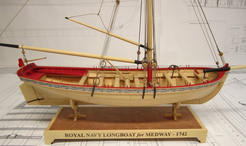
Chuck Posted September 25, 2018 Author Share #225 Posted September 25, 2018 Moving right along.....I will be working my way forward on the interior. None of the thwarts are glued into position just yet. There will be some things that need to be done to many of them as I work my way forward. For example, the seats in the cockpit need to be notched into the aft thwart. The seats are what I did next. The seats are laser cut in two layers just like the thwarts. The laser char was removed from their edges and then they were glued up so there was a decorative edge on one side like shown in the photos and on the plans. The two side seats were "tweaked" for the best fit first. They are laser cut a bit long on purpose to give everyone some wiggle room with this. You will be shaping and sanding and test fitting many times over until these fit properly. Everyone's model will very slightly so the notches for the frames will need to be filed in. BUT ..... -first, I beveled the aft edge of the seats so they sit flush against the transom which is angled. -then I held the seat in position against the frames so I could mark their locations on the seat. -I filed the notches for the frames a little at a time constantly testing the fit and adjusting. The edge of the seat against the frames also must be beveled to sit properly against the inside planking. -When the slots for the frame were acceptable, I laid the seat in position to cut its forward edge to length knowing that it will be notched into the last thwart. You can see the notch I filed into the thwarts below. Basically you must file away the lower layer of the thwart. In the next photo you can see how it looks after test fitting. Once they were glued into place, the center seat was treated the same way and adjusted to fit. This is how the whole model looks at this point. Its getting close now with only a few more details to add. The seats in the cockpit area will be painted red like one of the contemporary models. The two contemporary models are painted differently but I think I will follow the scheme shown below in the unrigged contemporary version. I also posted a photo of the rigged contemp. model to show you guys the difference. archjofo, Peter Bloemendaal, dvm27 and 38 others 41 Chuck Passaro - MSW Admin Sloop Speedwell - POF scratch Block Island Boat - POF scratch HMS Winchelsea - POB scratch build HM Cutter Cheerful - POB scratch build Royal Barge - POF scratch Medway Longboat- POF Scratch SYREN SHIP MODEL COMPANY Link to comment Share on other sites More sharing options...
shipmodel Posted September 25, 2018 Share #226 Posted September 25, 2018 Beautiful work, as usual, Chuck. Excellent joinery, especially the tricky notches in the floor planks for the ribs. Dan Chuck, thibaultron, EJ_L and 2 others 5 Current build -SS Mayaguez (c.1975) scale 1/16" = 1' (1:192) by Dan Pariser Prior scratch builds - Royal yacht Henrietta, USS Monitor, USS Maine, HMS Pelican, SS America, SS Rex, SS Uruguay, Viking knarr, Gokstad ship, Thames River Skiff , USS Oneida, Swan 42 racing yacht, Queen Anne's Revenge (1710), SS Andrea Doria (1952), SS Michelangelo (1962) , Queen Anne's Revenge (2nd model) USS/SS Leviathan (1914), James B Colgate (1892), POW bone model (circa 1800) restoration Prior kit builds - AL Dallas, Mamoli Bounty. Bluejacket America, North River Diligence, Airfix Sovereign of the Seas "Take big bites. Moderation is for monks." Robert A. Heinlein Link to comment Share on other sites More sharing options...
Chuck Posted October 2, 2018 Author Share #227 Posted October 2, 2018 I finished painting the cockpit seats. I also added the knees atop the last thwart and the knees and bracket along the inside of the transom. The knees on the transom were tricky but not too bad. They need to be beveled along the sides and back to fit the angles of the bulwarks and transom. Also note that the center bracket or panel on the transom was added to the top of the stern post and sanded flush. But before doing so, the stern post was reduced in height about 1/16" first. This allowed the top of the panel to sit flush with the top of the transom. Once this was glued into position and the knees added on either side, they were all sanded flush with each other so you couldnt see any seams. I used some wood filler for this too. Once painted it looks nice and clean. The notch on the center of that panel is used as a guide to file that same notch through the transom as well. You can see that in the photos. I hope that makes sense. Next up working my way forward will be the windlass. EricWilliamMarshall, Chuck Seiler, mtaylor and 28 others 30 1 Chuck Passaro - MSW Admin Sloop Speedwell - POF scratch Block Island Boat - POF scratch HMS Winchelsea - POB scratch build HM Cutter Cheerful - POB scratch build Royal Barge - POF scratch Medway Longboat- POF Scratch SYREN SHIP MODEL COMPANY Link to comment Share on other sites More sharing options...
Thistle17 Posted October 2, 2018 Share #228 Posted October 2, 2018 Chuck as I follow along I am entranced, but find myself losing track of the end product that will define the kit. Is your kit offering changed or is it going to be pretty much like Cheerful? Please, please, don't say as my wife says to me all the time..."Haven't we had this discussion before?" Joe EJ_L, Canute, mtaylor and 2 others 4 1 Link to comment Share on other sites More sharing options...
druxey Posted October 2, 2018 Share #229 Posted October 2, 2018 Nice set of stern sheets! thibaultron, Canute, mtaylor and 2 others 5 Be sure to sign up for an epic Nelson/Trafalgar project if you would like to see it made into a TV series http://trafalgar.tv Link to comment Share on other sites More sharing options...
Chuck Posted October 2, 2018 Author Share #230 Posted October 2, 2018 Thanks guys. Nothing has changed. There will be a full hull kit (everything you need in one box) followed by a smaller mini kit with all of the rigging and masting stuff. Just like the barge, virtually every part of this hull you saw me build so far is made of laser cut parts. In fact, I already have 10 kits already made up. But those are reserved for the guys in my local club. I literally just finished cutting the last sheets today. I am awaiting a new batch of milled cedar which should come in a couple of weeks. I will make 10 more right away. Each kit has about 25 sheets of laser cut parts. Thats just for the hull. As soon as the hull is finished and I finalize the plans, I will be ready to get this group started if there is still any interest. Once I get to that point I will ask again for a comitment in the online group before I start setting up a new forum area. All I really have left to make on the hull is the windlass, some metal work on the mast thwart, the thole pins, the roller at the bow....rudder and tiller. Thats really it. Then its time to rig it....first without sails.....then with sails. We need a minimum of 8 to start a group....but ten would be a real nice round number to start with. JeffT, Dubz, thibaultron and 6 others 9 Chuck Passaro - MSW Admin Sloop Speedwell - POF scratch Block Island Boat - POF scratch HMS Winchelsea - POB scratch build HM Cutter Cheerful - POB scratch build Royal Barge - POF scratch Medway Longboat- POF Scratch SYREN SHIP MODEL COMPANY Link to comment Share on other sites More sharing options...
NWSailor Posted October 2, 2018 Share #231 Posted October 2, 2018 Hello Chuck, waiting patiently for the kit release. thanks mtaylor, thibaultron, Canute and 1 other 4 Bill Link to comment Share on other sites More sharing options...
Thistle17 Posted October 2, 2018 Share #232 Posted October 2, 2018 Thanks Chuck I too am waiting patiently for the release outside your club. Joe mtaylor, Canute, EJ_L and 1 other 4 Link to comment Share on other sites More sharing options...
Richmond Posted October 2, 2018 Share #233 Posted October 2, 2018 Beautiful work Chuck. I'm still in. Canute, thibaultron, EJ_L and 1 other 4 Current Builds Mikasa by I Love Kit - 1:200 - Plastic HMS Beagle by Occre - 1:48 - Wood Link to comment Share on other sites More sharing options...
Landrotten Highlander Posted October 2, 2018 Share #234 Posted October 2, 2018 am in as well thibaultron, mtaylor, EJ_L and 1 other 4 Heghlu'meH QaQ jajvam Slainte gu mhath L.H. Link to comment Share on other sites More sharing options...
Chuck Posted October 2, 2018 Author Share #235 Posted October 2, 2018 Thank You gentlemen!! Just a quick comparison as the new larger and improved longboat is far enough along. You can see how different and more elegant the shape is on the newer version. It has a much fuller bow and as you proceed to the stern the newer version has a more pleasing curve. You can see many other differences as well. The floorboards and other features are more detailed and true to the Medway contemporary model. realworkingsailor, Landrotten Highlander, Mike Y and 25 others 27 1 Chuck Passaro - MSW Admin Sloop Speedwell - POF scratch Block Island Boat - POF scratch HMS Winchelsea - POB scratch build HM Cutter Cheerful - POB scratch build Royal Barge - POF scratch Medway Longboat- POF Scratch SYREN SHIP MODEL COMPANY Link to comment Share on other sites More sharing options...
Tigersteve Posted October 2, 2018 Share #236 Posted October 2, 2018 True, but you still designed a masterpiece with that longboat for Model Shipways. Steve Obormotov, mtaylor, thibaultron and 2 others 5 Current: Mayflower- Model Shipways Completed: Lowell Grand Banks Dory- Model Shipways English Pinnace- Model Shipways 18th Century Longboat- Model Shipways Link to comment Share on other sites More sharing options...
JeffT Posted October 3, 2018 Share #237 Posted October 3, 2018 Still interested Seventynet, thibaultron, mtaylor and 2 others 5 Jeff In progress: Medway Longboat 1742 - Syren Ship Model Company -1/2" scale USS Constitution - Model Shipways - Scale 1:76 HMS Granado - CAF Model - 1:48 HMS Sphinx - Vanguard Link to comment Share on other sites More sharing options...
MEDDO Posted October 3, 2018 Share #238 Posted October 3, 2018 Chuck I think you are going to get a lot more than just 8-10 in the group. Chuck, EJ_L, mtaylor and 3 others 6 Michael Shipwrights of Ohio Current Build: ... Completed Builds: Queen Anne Barge - Syren, Pinnace - MS, Halifax 1768 - LSS, Murrelet - Pygmy, Swift 1805 - AL Link to comment Share on other sites More sharing options...
johncole Posted October 3, 2018 Share #239 Posted October 3, 2018 I'm still in!! John EJ_L, thibaultron, mtaylor and 1 other 4 Link to comment Share on other sites More sharing options...
Erik W Posted October 3, 2018 Share #240 Posted October 3, 2018 Chuck, I haven't been in ship-mode for quite a while now. Real life has taken up too much of my time and mental space this year. I recently returned from a trip to Denmark, where I visited the National Maritime Museum and the Viking Ship Museum. Feeling my ship modeling interest being rekindling, I thought I'd check in here. Wow! I'm quite excited by this longboat kit you're working on. While I'm hoping to channel my renewed interest into picking up where I left off with my Cheerful build, this longboat looks like it will be a phenomenal kit. I'm impressed with how much more realistic this larger scale longboat looks, especially when compared to the 1/48 scale boat. Though I understand the size from the dimensions you've given, I'm having a hard time picturing the actual real world size of this boat. Any chance you can post a photo with something we can all relate to, like a can or bottle of soda/beer, or coin, or lighter, etc. I know that's kind of gimmicky, but 1/24 scale isn't something we're used to seeing everyday. Thanks, and glad to see after my time away that you're still doing what you do best! Erik EJ_L, mtaylor, Stuntflyer and 4 others 7 Current build: HM Cutter Cheerful - Scratch Build - 1:48Finished build: 18th Century Longboat - Model Shipways - 1:48 Link to comment Share on other sites More sharing options...


Recommended Posts