Fam Posted November 10, 2014 Share #1 Posted November 10, 2014 Hi all this is the opening of my shipyard for building this little ship. Well... maybe little in the real world, because due to the scale the complete model will be longer than 1 meter, so quite huge for normal standards (I mean the standard size of Italian houses). An explanation about the title of this topic: ‘Brick de 24’ is the name of a class of ships, brigs type, whose main weapons were 24pdr carronades, in the number of 14. Other weapons were two 6pdr long guns. They were designed (most of them) by the master designer Pestel and built between 1806 and 1813. Many more information can be read here: http://modelshipworld.com/index.php/topic/7795-brick-de-24-by-jackaubrey-148-scale/#entry231121 in the topic of my good friend, and co-builder, Jack Aubrey. The ship plans are available in the excellent monography “Le Cygne” issued by Ancre, including 19 sheets of 1:48 scale detailed drawings and plans. This will be a joint construction: JA started before, and completed the most difficult job of transferring the Ancre plans to AutoCAD. I assisted at the starting of his project and was really impressed by the beauty of this ship: I already had lot of pictures of Le Cygne and Le Cyclope (another ship of the same class) in my database, and have always looked at them as a possibility for the future. So when JA started the possible future become the present, and I contacted him to ask if I could joint his project. So, before anything else, I have to say THANK YOU SO MUCH to my friend Sergio for allowing me to join him in the project and for providing me, for free, the CAD plans to start with my model. My copy of the monography has been shipped and is on the way, but unfortunately I’ll have to wait for it until the end of this month. As JA explained, we decided to build a different shipmodel with respect to those already existing, namely Le Cygne, Le Cyclope, Le Cureiux and L’Esperance. More, JA decided (or initially thought about) to show her after it was seized by the Royal Navy and re-commissioned for active service with the British, so with some modification to the original Ancre plans. I’ve not decided yet what to do, but I will probably stick to the French configuration making good use of the excellent Ancre plans. Which ship? We had a long discussion about this item, and I told Sergio that I will leave to him the priority of choice among the names that he elected as preferred. Therefore I will decide after him, but the rose of candidates is restricted among: - Le Nisus (1805), seized in 1809 (--> HMS Guadeloupe) - Le Milan (1806), seized in 1809 (--> HMS Achates) - Le Phaéton (1806), seized in 1806 (--> HMS Mignonne) - Le Colibri (1809), seized in 1809 (--> HMS Colibrì) The figurehead will be fictious, as no information exists for these ships, but obviously based on the name of the ship. I will find in internet some beautiful picture of that birds and do my best to get a decently carved figurehead. The model The size is quite large, according to Ancre website it will be 74cm long (the hull, 116cm fully rigged), 17cm wide (52cm rigged) and 17cm high (86cm tall fully rigged). The wood will be... ehm ... well, whatever I manage to find. I mean, it’s quite difficult here in Italy to find sources of good wood for modelling at acceptable prices. I have some pearwood available, some other is seasoning, will use poplar plywood for the hull structure, probably limewood for the deck, a reddish variant of pinewood for the bulwarks, yet don’t know what for the hull planking (well, the hull is coppered so probably it is not important). The model will be POB type. After this long presentation... October 19th, 2014 Grand opening of the shipyard, the first sawdust is produced... My best regards Fam ChrisLBren, drhemlock2, avsjerome2003 and 8 others 11 Quote Joint building: Brick de 24, 1/48, jointly with Jack Aubrey (POB from Ancre plans) Works in progress: USS Constitution Cross Section, 1:93 (POF bashed from Mamoli kit) Completed models: Santìsima Trinidad, 1/90 (POB heavily modified DeAgostini kit) Genoan Pinco, 1/50 (POB bashed from Euromodel plans - my current avatar) Viking Knarr, 1/72 (POF from Dusek kit) Link to comment Share on other sites More sharing options...
Fam Posted November 10, 2014 Author Share #2 Posted November 10, 2014 (edited) November 01st, 2014 A few days later, this is how she looked. I logged about 15 hours to get at this stage: all the bulkheads cut, the false keel cut, the bow fillers and transom timbers cut, all the parts finished, checked and dry fitted. Some detail about my technique: I used 5mm thick poplar plywood, so had to use a dedicated version of the plans that JA kindly provided. All the parts are hand-cut with a manual scroll-saw, as I’ve little room in my 3x3m workshop for bulky tools and machines (that will remain, anyway, my dream ). The bulkheads are cut for a tight fitting with the false keel, considering that the paper formers still have to be peeled away. I used a stick glue for the formers, that is quite easy to remove but strong enough to support the stress of the saw blade. The attentive observers could note that something is different from JA’s model: - the most evident is the number of bulkheads. While JA decided to reduce it to the minimum strictly required for the building, I retained all the original 22 bulkheads that he had draught. The only missing is the #5, corresponding to the main mast slot. Even for the foremast slot, I managed to arrange a solution that uses the bulkhead itself as one of the side walls for the mast slot. Reason for this? No real need, call it a personal fixation, or whatever you prefer: I like seeing the shape of the hull coming out from the very beginning. Even with my Pinco I used the same approach and doubled the number of bulkheads w.r.t. those required by Euromodel plans. - Another evident difference is the fact that I didn’t use the two longitudinal beams, as I deemed them not necessary if the stiffeners between the bulkheads are used (that is my program). - A third thing is that I did not use the joints strengtheners for the 3 keel pieces: again, to me these are unnecessary pieces because the building base holds the keel firmly and straight aligned until all the stiffeners are installed. Well, same direction, slightly different paths... When I had arrived at this stage, JA warned me that his plans contained two minor but significant errors: the first dealt with the stations of the bulkheads along the keel, and instead of trying to fix it I resolved the problem by cutting 3 new pieces for the entire false keel. The second error dealt with the height of the deck with respect to the top of the bulwark (is this the name?) toptimbers. As JA better explained in his build-log, the error was due to a misinterpretation of a drawing not in the correct scale. Too late for him, in time for me (thx JA!!). I recalculated the correct height of the deck, considering the thickness of the false-deck and deck planks I intended to use, and then I only had to remove 0.8-1mm from the top profile of each bulkhead. Easily done with the scroll saw. The last difference for today is the way I arranged the transom timbers (hope this is the correct name): I joined them to the last and last-but-one bulkheads, to get a stronger joint. This will be a weak point of the structure until they will be joined by other pieces, which will be my next task. (BTW, can you see how I moved 2.5mm aft the bulwarks without changing the original CAD plans?) The transom timbers are shaped so that they form a curved line when seen from above and from behind, matching the transom shape on the plans (will be seen later). That’s all for today Ciao a tutti FAM Edited November 11, 2014 by Fam SaturnV, Omega1234, Jason and 11 others 14 Quote Joint building: Brick de 24, 1/48, jointly with Jack Aubrey (POB from Ancre plans) Works in progress: USS Constitution Cross Section, 1:93 (POF bashed from Mamoli kit) Completed models: Santìsima Trinidad, 1/90 (POB heavily modified DeAgostini kit) Genoan Pinco, 1/50 (POB bashed from Euromodel plans - my current avatar) Viking Knarr, 1/72 (POF from Dusek kit) Link to comment Share on other sites More sharing options...
Mc Fly Posted November 10, 2014 Share #3 Posted November 10, 2014 Smart begin. Quote Link to comment Share on other sites More sharing options...
mtaylor Posted November 11, 2014 Share #4 Posted November 11, 2014 An excellent start, Fam. I'm looking forward to seeing more.. Quote Mark "The shipwright is slow, but the wood is patient." - me Current Build: Past Builds: La Belle Poule 1765 - French Frigate from ANCRE plans - ON HOLD Triton Cross-Section NRG Hallf Hull Planking Kit HMS Sphinx 1775 - Vanguard Models - 1:64 Non-Ship Model: On hold, maybe forever: CH-53 Sikorsky - 1:48 - Revell - Completed Licorne - 1755 from Hahn Plans (Scratch) Version 2.0 (Abandoned) Link to comment Share on other sites More sharing options...
Fam Posted November 11, 2014 Author Share #5 Posted November 11, 2014 November 06th, 2014 Let’s go on... I spent some days in collecting all the parts to build the base-board. The copyright of its layout is 100% of JA: it works, so why not copying?? Another friend of mine, in the Company I work for, kindly cut the upright posts with a large circular saw to ease my work. Then I quickly assembled all the parts and immediately started gluing the frames. Well... not so immediately, because each bulkhead needed cleaning from paper formers, filing and sanding the borders and finally fine trimming the joints slot with the keel. Anyway, the following pictures show the start of the gluing phase. I always had used LEGO blocks to ensure the bulkheads are correctly at a square angle to the keel, and this time was not different (thx to my son who lent me the pieces I needed !! ) November 09th, 2014 3 days later, the job is completed. This is a minor milestone in the project, for me, so I shot lot of pictures in good daylight (I usually work at night in artificial light). Here are three of these shots: can you see what I wrote about the shape of the hull being so evident thanks to the large number of bulkheads? I also tested the flow of the hull lines from bow to stern with a thin and long plank, and the result is really outstanding! No corrections to be done, perfect alignment of the frames and top-timbers: ready to start beveling the bulkheads before laying the planks. But many other works have to be completed before, to fix the inherent weakness of the stern timbers and give a proper shape to the transom and bow. Finally, I show the details of the masts steps and the bow timbers (maybe ‘hawse timber’ is more correct?) - For the mainmast step I sandwiched two battens of the required thickness (2.5mm) between the keel and another piece of plywood, so that the width of the housing is exactly 10mm (that is the diameter of the mainmast according to Lees, the reference we decided to use preliminarly). This creates a squared housing 10x10mm, 50mm deep, where the dummy dowel for the mainmast fits tightly. - For the foremast step I used the same concept, but the side plywood pieces are directly notched into bulkhead n. Va for a stronger joint. In this case the size of the housing is 9x9mm, again 50mm deep. - To conclude, I’ve joined the top parts of the two bow fillers, representing something similar to the innermost hawse timbers, with horizontal plywood pieces: they have been glued in position and then suitably shaped. This fixes an error I did in interpretation of the required height for these parts. I still have to check this height with the top timbers of the bulkheads, but this is an easy job. Here it is also evident that I already cut the toptimbers of the foremost bulkhead (n. VIIIa) with double width, to account for the subsequent beveling. That’s all for today FAM jack.aubrey, avsjerome2003, Erebus and Terror and 8 others 11 Quote Joint building: Brick de 24, 1/48, jointly with Jack Aubrey (POB from Ancre plans) Works in progress: USS Constitution Cross Section, 1:93 (POF bashed from Mamoli kit) Completed models: Santìsima Trinidad, 1/90 (POB heavily modified DeAgostini kit) Genoan Pinco, 1/50 (POB bashed from Euromodel plans - my current avatar) Viking Knarr, 1/72 (POF from Dusek kit) Link to comment Share on other sites More sharing options...
Fam Posted November 12, 2014 Author Share #6 Posted November 12, 2014 November 11th, 2014 Next task, as said above, was to strengthen the weak transom timbers in preparation for the bulkheads bevels sanding and to get an even surface ready to receive the transom piece. So the first thing was to prepare a cardboard template of the transom to check the proper shape and alignment of the transom timbers. The next picture shows these pieces from the side and permits to appreciate the slight offsets of the two side timbers w.r.t. the central timbers: - the vertical downward shift, about 2mm, is automatically obtained thanks to the curvature of the bulkheads’ upper profile (i.e. of the deck) where the transom timbers are fixed. - the horizontal offset is obtained by shifting the side timbers forward by 4mm (related to the fore&aft position of the central timbers and aftermost bulkhead n.XIII). Given the aft slope of the transom above the knee (pointed to by the red arrow), this horizontal offset then reduces to about 3mm as an effect of the above mentioned vertical shift. The curvature of the transom can be better seen in the following picture, where the transom template is test fit. And here is how I checked the proper alignment of the transom timbers: the building base is set perfectly horizontal (as much as possible with the tools I own ), the verticality of the keel is adjusted (square angle to the base board), a reference horizontal line is drawn on the transom template and checked with a spirit level. After the transom is correctly positioned and oriented (horizontally, vertically and side inclination), its position is marked on the transom timbers as a reference. In particular, the lower border of the transom is checked to lay along the alignment of knees of the transom timbers (minor adjustments to these was required). With all these checks done, the two circular holes in the transom are perfectly located with respect to the transom timbers: now it is possible to install the joining pieces that strengthen the latter and create the base for the shape of the transom itself. Alignment of these pieces is not important, provided that the area surrounding the circles is left free for a filler piece on more ‘noble’ wood (this area will be visible, so plywood is forbidden!!). The last picture shows the area where the lower counter will be installed, below the transom. Another cardboard template is needed for the counter, to check the correct shape of the transom timbers below the knee where it is located. This will be my next task, together with the addition of other reinforcements outside of the side transom timbers and with the bow filler pieces. All these check and verification activities will be alternated by the cut and gluing of the pieces in-between each couple of bulkheads, creating a strong and stiff structure for the hull. Stay tuned! FAM aviaamator, hexnut, Mfelinger and 7 others 10 Quote Joint building: Brick de 24, 1/48, jointly with Jack Aubrey (POB from Ancre plans) Works in progress: USS Constitution Cross Section, 1:93 (POF bashed from Mamoli kit) Completed models: Santìsima Trinidad, 1/90 (POB heavily modified DeAgostini kit) Genoan Pinco, 1/50 (POB bashed from Euromodel plans - my current avatar) Viking Knarr, 1/72 (POF from Dusek kit) Link to comment Share on other sites More sharing options...
Fam Posted November 18, 2014 Author Share #7 Posted November 18, 2014 (edited) November 18th, 2014 Hi all, some slow progress in my shipyard. Next steps: the counter and hull preparation for planking. As anticipated above, for the lower counter I prepared another cardboard template. I had some problem in getting the correct shape, as the only views I own (my monography is not arrived yet, so I have to rely on scanned copies kindly sent by Jack Aubrey!) are seen directly from the stern, so they are correct in athwartship dimension but compressed in the vertical direction. I had to play a bit with geometry, trigonometry and graphic tools to get the correct shape, but in the end I managed to obtain it. The next pictures show the Counter template dry-tested in position: the hole for the rudder is apparently smaller than required, but the plans provide the correct shape and size for this detail and a section view of the transom-counter-rudder head, for its correct position. So I glued another paper template of the hole to the Counter template and cut the hole to check its position with respect to the false keel and transom timbers. I’m not fully confident about its size, yet: I'll recheck it when the sternpost piece will be available. Nevertheless, this layout permits me to adjust the position of the counter more accurately. I also managed to bevel the template to improve the joint with the transom, so I feel its position is pretty close to be definitive. Another internal view of the rudder hole... ... just showing how the internal transom timbers are exactly separated by the size of the rudder hole. The third picture also shows the last side reinforcements to the transom timbers: this 3rd layer of plywood adds enough material to permit shaping the transom to its final size. This technique is my ugly attempt to copy the same used by Chuck, and I give to him full credit for having shown us what has become, to me, one of his most efficient trademarks in hull structure design (his most recent example, the HM cutter Cheerful, is a fantastic example!). In the meantime, I continued adding plywood blocks in between the bulkheads, until obtaining the needed stiffness for the structure. The lateral stiffness has increased a lot after I’ve completed this addition, but torsionally is still not enough so I will continue using the base building board as long as possible. The latter picture also shows the bow filler pieces, another addition of these days. Another cardboard template was used to draw the shape of the hull at deck level, thus defining the amount of material to be removed. After all these dry tests, I felt sufficiently confident about the lower counter, so decided to create and glue the real piece. It is made from 0.8mm plywood, and obviously it is only the base for the following counter planking. My last three days were spent in sanding, and shaping, and filing, and ... cough cough ... making lot of sawdust. Regardless of the vacuum cleaner continuously working, virtually every surface of my workshop has now a pretty layer of dust!!! I’m looking forward to completing this phase and doing some cleaning to the room! Another two pictures just taken this early morning, showing the stern and bow filler blocks shaped, the lower counter and the filler pieces in the transition area in between bulkheads XII and XIII (to help planking). Some more sanding and I’m almost ready to start planking the hull Regards FAM Edited November 18, 2014 by Fam jack.aubrey, Chuck, mtaylor and 13 others 16 Quote Joint building: Brick de 24, 1/48, jointly with Jack Aubrey (POB from Ancre plans) Works in progress: USS Constitution Cross Section, 1:93 (POF bashed from Mamoli kit) Completed models: Santìsima Trinidad, 1/90 (POB heavily modified DeAgostini kit) Genoan Pinco, 1/50 (POB bashed from Euromodel plans - my current avatar) Viking Knarr, 1/72 (POF from Dusek kit) Link to comment Share on other sites More sharing options...
Chuck Posted November 22, 2014 Share #8 Posted November 22, 2014 That look like a very well constructed skeleton. Its looking faired and true. Well done!! Quote Chuck Passaro - MSW Admin Sloop Speedwell - POF scratch Block Island Boat - POF scratch HMS Winchelsea - POB scratch build HM Cutter Cheerful - POB scratch build Royal Barge - POF scratch Medway Longboat- POF Scratch SYREN SHIP MODEL COMPANY Link to comment Share on other sites More sharing options...
druxey Posted November 22, 2014 Share #9 Posted November 22, 2014 All that careful work will pay off very shortly, FAM! Quote Be sure to sign up for an epic Nelson/Trafalgar project if you would like to see it made into a TV series http://trafalgar.tv Link to comment Share on other sites More sharing options...
Fam Posted November 24, 2014 Author Share #10 Posted November 24, 2014 (edited) November 24th, 2014 Hi all many thanks for the likes and for the comments, I really appreciate! I've just started applying the first 2 planking strips, from the deck level downward, and another strip for the garboard plank, and confirm the impressions: they go on very easily at the bow, while at the stern it was a little bit more tricky but only due to the shape of the hull just under the transom, at the joint with the counter where a sharp bending and torsion of the planks are required. I've read again attentively (I think it's the third or fourth time, indeed!) the "Simple hull planking techniques for beginners" manual, I'll try to go with this technique as much as possible. Nonetheless I don't have any possibility to get large planks, for using the spiling techniques at its best (as shown by Chuck on the HMS Whinchelsea). I'm not worried very much about this, as the hull will be completely coppered, so the layout of the planking will be hidden by the copper plates. So I'll use as many drop-planks or stealers as required, but will try to comply with the planking "rules" as much as possible. I've not received my monography from Ancre yet, so I'm only relying on a couple of 1:48 scale drawings to have an idea of the number and thickness of planks to be used. The wales will be 2.5mm thick at their thicker position, second and third wale's planks from the top. Then the thickness will gradually decrease to 1.75mm at the bottom of the wale (4 plank rows more below), where it merges into the hull planking without steps. The upper plank of the wale is at deck level and is 2.25mm thick. Above the wale there is a 0.5mm step, and the planks thickness decreases to 1.75mm for the first external plank of the bulwark. From this level upward the thickness further decreases gradually to 1mm at the top of the bulwark. The following picture shows what I'll try to get: How? - For the bulwark planking I'm getting several billets of a type of pine-wood, called 'Cirmolo' in Italian, which is amber-reddish coloured. This part will remain in the natural wood colour down to the gunport sills. Below this level, it will be painted black. - For the planking of the wales I'm using limewood planks 1.5mm thick by 5mm wide. I'll use a double layer at the wales, sanded to the required thickness. - Below the wale I'll still use the same limewood planks and will add a second layer of 0.5mm veneer below the area where 2mm thickness is required. It seems a quite strange approach, but unfortunatly I have always had great difficulty in finding suitable wood pieces to obtain planks and, even more difficult, to have it cut to the suitable thickness. I've got no machines and sophisticated tools, so I always need to rely on external help ;-( That's all for today, still no pictures of the model for a while. Ciao Fam Edited November 25, 2014 by Fam antanasp, jack.aubrey, WackoWolf and 1 other 4 Quote Joint building: Brick de 24, 1/48, jointly with Jack Aubrey (POB from Ancre plans) Works in progress: USS Constitution Cross Section, 1:93 (POF bashed from Mamoli kit) Completed models: Santìsima Trinidad, 1/90 (POB heavily modified DeAgostini kit) Genoan Pinco, 1/50 (POB bashed from Euromodel plans - my current avatar) Viking Knarr, 1/72 (POF from Dusek kit) Link to comment Share on other sites More sharing options...
jack.aubrey Posted November 24, 2014 Share #11 Posted November 24, 2014 Very interesting and detailed build log . . I didn't read it before. I bookmarket it for the future. Jack.Aubrey Quote Link to comment Share on other sites More sharing options...
Fam Posted November 28, 2014 Author Share #12 Posted November 28, 2014 (edited) November 28th, 2014 Hi all a small update from the "Brick de 24" shipyard: I’m fully into the planking phase now. I had to give up with my ideas of planking techniques, spiling and all that sort of things: there is no chance for me to get large planks, I only have 5mm wide limewood strips and was not able to find anything else. I took some measurements, following the guidelines of Chuck’s “Lining off your hull for planking” tutorial. But the shape of the hull at the bow is such that spiling is required from the very beginning, even at the wales. So, for the first planking I’m back to my standard techniques, with several drop planks and stealers wherever needed. For the second planking I had some ideas, but first of all a couple of pictures of the model: Sorry for the quality of pictures, my tablet camera is not it’s better feature! But first of all I added to the keel a couple of hexagonal nuts, ready to house the bolts for fixing the model to the display base. This is the first time I try something similar, but (as usual) lot of pictures are available here on MSW, so just copied! Yesterday I had a hard disappointment and my disillusion grow up again, once more after several other episodes! I went to pick up my boards of Cirmolo cut to 6mm thickness, and ... totally useless for my scopes. The texture is too coarse, unsuitable for 1:48 planking to remain in natural wood color. Of course it's totally my fault, due to ignorance on timber characteristics: when I bought the Cirmolo log it appeared as a god choice, the color was appealing, the grain was thin. But after cutting, this is the result: Even if cutting the planks edgewise (which was the plan to get 6mm wide planks), the texture will remain very evident and unsuitable for the bulwarks. So now my hope is back to the original Pearwood, a bit darker but with adequate grain: (the color in the picture is a bit altered). New hope also from the log of boxwood I'm getting prepared right now, we'll see how it looks like! What can I do with that Cirmolo? This is my idea: I'll cut one board into 6mm planks, and will ask the carpenter to reduce another of the boards, the thinner is 4mm thick, to just 2mm (or even 1.5, if possible) thickness. This should be suitable for the wales second planking, finally making good use of the spiling technique. So, stay tuned and a big ciao from FAM Edited November 28, 2014 by Fam mtaylor, cog, avsjerome2003 and 3 others 6 Quote Joint building: Brick de 24, 1/48, jointly with Jack Aubrey (POB from Ancre plans) Works in progress: USS Constitution Cross Section, 1:93 (POF bashed from Mamoli kit) Completed models: Santìsima Trinidad, 1/90 (POB heavily modified DeAgostini kit) Genoan Pinco, 1/50 (POB bashed from Euromodel plans - my current avatar) Viking Knarr, 1/72 (POF from Dusek kit) Link to comment Share on other sites More sharing options...
Fam Posted December 2, 2014 Author Share #13 Posted December 2, 2014 My copy of the monography just arrived yesterday evening... 30 days from Nice ot Milan... no other comments needed!! FAM antanasp 1 Quote Joint building: Brick de 24, 1/48, jointly with Jack Aubrey (POB from Ancre plans) Works in progress: USS Constitution Cross Section, 1:93 (POF bashed from Mamoli kit) Completed models: Santìsima Trinidad, 1/90 (POB heavily modified DeAgostini kit) Genoan Pinco, 1/50 (POB bashed from Euromodel plans - my current avatar) Viking Knarr, 1/72 (POF from Dusek kit) Link to comment Share on other sites More sharing options...
cog Posted December 2, 2014 Share #14 Posted December 2, 2014 I had a monograph from them in a week ... Quote Carl "Desperate affairs require desperate measures." Lord Nelson Search and you might find a log ... Link to comment Share on other sites More sharing options...
Fam Posted December 2, 2014 Author Share #15 Posted December 2, 2014 (edited) Too easy that way, you don't have the Italian Mail Service!! Edited December 2, 2014 by Fam cog 1 Quote Joint building: Brick de 24, 1/48, jointly with Jack Aubrey (POB from Ancre plans) Works in progress: USS Constitution Cross Section, 1:93 (POF bashed from Mamoli kit) Completed models: Santìsima Trinidad, 1/90 (POB heavily modified DeAgostini kit) Genoan Pinco, 1/50 (POB bashed from Euromodel plans - my current avatar) Viking Knarr, 1/72 (POF from Dusek kit) Link to comment Share on other sites More sharing options...
cog Posted December 2, 2014 Share #16 Posted December 2, 2014 That must be your advantage Fortunately youfinally got it! Fam 1 Quote Carl "Desperate affairs require desperate measures." Lord Nelson Search and you might find a log ... Link to comment Share on other sites More sharing options...
Fam Posted December 15, 2014 Author Share #17 Posted December 15, 2014 Hi all, I’m back again with the Brick de 24 shipyard! Past two weeks were full of satisfaction for me: I managed to reach 3 milestones, two major and one minor, in my shipyard activities... unfortunately my job kept me far from posting the updates here, so I’ll show you what I did respecting the chronology... hope you’ll enjoy it! December 15th, 2014 First of all, even if a bit Out-of-Topic, I’m proud to introduce you to the first of my major achievements: The Viking 11th century Knarr is completed! It started as a side project, while masting the USS Constitution Cross Section... then the latter was stopped while waiting for the blocks from The Syren Company, and the Knarr become the main project. Then I started the Brick, and it became again a side project, but I continued working on it to give some rest to my aching fingertips (will tell later!)... It is a Dusek small kit, quite interesting and quick to build until the planking phase is started... then headaches started... definitely klinker planking is not easy!! Hystorical sources are... scarce, if not absent. The kit is based on the remaining of Skuldelev 1 wreckage, which can be visited in the Viking Ship Museum in Roskilde, Denmark. I slightly modified the shape of the keel tips, to give it a ... more Viking looking... well, it is intended to be a personal interpretation of a type more than the reproduction of the real ship, but this is the only modification I introduced! Some interesting information on the ship can be found on this fantastic site: http://home.online.no/~joeolavl/viking/vikingknarr.htm and some other information about the building techniques are here: http://home.online.no/~joeolavl/viking/norse-shipbuilding.htm I mainly based my Knarr rigging on the Borgundknarren replica, and on some information I exchanged with Mr Jack Panzeca here on MSW. As this is the build-log of the Brick de 24 I’ll post only 3 pictures of it. General views The helmsman position mtaylor, antanasp, Daryl and 2 others 5 Quote Joint building: Brick de 24, 1/48, jointly with Jack Aubrey (POB from Ancre plans) Works in progress: USS Constitution Cross Section, 1:93 (POF bashed from Mamoli kit) Completed models: Santìsima Trinidad, 1/90 (POB heavily modified DeAgostini kit) Genoan Pinco, 1/50 (POB bashed from Euromodel plans - my current avatar) Viking Knarr, 1/72 (POF from Dusek kit) Link to comment Share on other sites More sharing options...
Fam Posted December 15, 2014 Author Share #18 Posted December 15, 2014 And now I’ll continue with the Brick de 24 December 05th, 2014 Planking, planking, planking... After I gave up with the spiling technique for the first planking, I started at a slow pace proceeding at the same time on both sides. Standard technique, learnt with the Santisima Trinidad kit, standard problems! At the bow the planks, that cannot be curved edgeward, tend to climb up (down in the photo where the hull is capsized) so I had to force them a little bit, as much as possible without letting them to raise from the bulkheads, and to introduce several drop-planks. The same happens at the sterns where the convexity leads to converging planks. On the keel side, conversely, the Garboard plank was easily added and then I started planking downward, with the addition of some stealer where the hull is concave. Can you see all that pins with a tiny plastic ball tip? They are the reason for my fingertips aching... because modeling is a pleasure but sometimes also a pain...;-) Yes, I’m a Queen and Freddie fan!! Consider that I also sliced one fingertip while shaping the stealers... So no more than 3-4 strakes per evening! December 12th, 2014 One week later (while at the same time working on the Knarr), this was the status of the planking... December 13th, 2014 The following evening... December 14th, 2014 ... and finally yesterday night ... Minor milestone achieved: the starboard side is fully planked from the keel to the wale! Next task: complete the port side, obviously... before Christmas I hope ;-) In the meanwhile... the second major milestone: getting the required wood types and having them properly cut and sanded to the thickness I need. DONE!! Firstly, I tried to cut 1.75mm planks from the Cirmolo I already have. Remember? I need them for the wales, to be overlaid above the 1st limewood planking. This is the result: very easy to slice with a "Super-Cut" blade in my Proxxon KS230, coarse pink-ish to beige texture, quite easy to bend, also accepts a good amount of torsion (90deg in a 300mm long strake) and some edgeward bending. But the most amusing thing is... the smell of it! When freshly cut it’s like being in a Swiss mountain hut, all built in wood... I love it! Here is it: And this is the wood I managed to find: Boxwood in two different shades, one is so yellow that seems to be stained, the second (which I haven’t cut yet) is more amber tone. I plan to use it for the bulwark internal and external planking (the yellowish one) and for the figurehead (the amber one). Limewood, the different shades are only due to the orientation of the pieces w.r.t the light. I plan to use it for the deck planking. Pearwood. This shade is much more reddish than the shade I already have. I will use it for the keel, cutwater, sternpost, gunport linings and deck fittings. Tanganika veneer. To be used for the second planking. Ramin. To be used for various deck fittings and guns carriages Not big quantities, but I hope enough for the scopes I intend to use it... Here they are: Best regards Fam archjofo, cog, antanasp and 6 others 9 Quote Joint building: Brick de 24, 1/48, jointly with Jack Aubrey (POB from Ancre plans) Works in progress: USS Constitution Cross Section, 1:93 (POF bashed from Mamoli kit) Completed models: Santìsima Trinidad, 1/90 (POB heavily modified DeAgostini kit) Genoan Pinco, 1/50 (POB bashed from Euromodel plans - my current avatar) Viking Knarr, 1/72 (POF from Dusek kit) Link to comment Share on other sites More sharing options...
Fam Posted December 23, 2014 Author Share #19 Posted December 23, 2014 December 23rd, 2014 Hi to all the MSW members, as promised, I’m posting a final update before stopping the shipyard for the Christmas holidays. In the last week I reached a major milestone, i.e. completing the lower hull planking. Now the 1st layer of limewood strips is set on both hull sides, from the upper border of the wale downward to the keel. I took a couple of work sessions to smooth out all irregularities and bumps in the planking, by sanding with progressively finer sandpaper: started with 80 grit, then 120 and finally 240, for a smooth and even finish. No need of filler in any point. I’d like to show you the result with the following pictures. I am in the background because this permits to appreciate the size of the hull, which is quite large: about 71cm long, 15cm high, 20cm wide. Next job was to trim the planks closer to their final size and start refining their stern side. Well, this was done during the final phases of the hull sanding, to ease the smoothing of the surface in proximity of the stern counter. This is why in the next pictures the hull finish is not smooth yet. The next picture shows how the planks running into the counter were cut to permit accommodating the counter template. After this was obtained, I cut the rudder hole into the counter base plywood, in order to facilitate the following works on this detail. The job was done by firstly drilling lot of small holes along the inside of the hole profile, then joining them with a cutter and finally cleaning the hole borders with needle files and grinders. Next was the preparation of the first counter plank, whose scope is also to finish the running of the hull planks. I soaked a piece of limewood strip for about 15 minutes, then tried edge-bending it with the help of three clamps and a piece of suitably shaped scrap plywood. When released from the clamps (after a couple of hours) the wood was completely dry, the spring-back was minimal and the shape was maintained. I was so pleased by this result that later I decided to try the same technique with the bulwark 2mm thick boxwook planks (see below). Well, the result was unexpectedly negative: the spring-back was so large that the shape was completely lost. I have the doubt that probably this was due to the different characteristics of the wood, much more dense and compact w.r.t. the limewood, but also to the larger thickness (2mm vs 1.5mm) requiring much longer soaking in water and more time into the clamps. Will try again changing these parameters, but if anybody has any suggestion for bending the boxwood I will appreciate and try it immediately. Next picture shows the first counter plank positioned, while glue is setting. A second plank was fitted right below, needing some width adaptation. The shape of the counter is such that its upper and lower border does not run parallel to each other, so the width of the plank needs to be narrower at the extremes and wider in the middle. Five full planks are needed for the counter, plus a filler at the joint with the transom. With the hull planking completed, I could not resist the temptation to try my new wood reserve! So I started cutting the planks for the bulwark exterior. This area is partially painted black, from the wale up to the gunport sills. Then from this level up to the gunwales the color is natural yellowish, with an ochre tone. For this reason I decided to use boxwood to plank the bulwarks all the way up to the gunwale. As stated above (Nov 24th) the planking thickness above the wale starts with 1.75mm for two stakes, then there is a small step (0.5mm), reducing to 1.25mm and fading to 1mm thickness at the top of the bulwark: four strakes are required above the gunport sills up to the gunwale. So started calculating the amount of planks require for the first thicker band. The Ancre monography states that hull planks length varied between 30 and 40 feet, which translates into between 190 and 254mm in 1:48 scale, if British feet measure is used for conversion. But my question is... did French shipwrights use British units during the Napoleonic Wars? I don’t think so! Additionally, conversion into 1:1 scale gives planks of 9-12m length, that in my opinion is a bit excessive... but again I’m ready to change mind if anyone has suggestions... I also had to consider that my planks need to seat on the top-timbers, so in the end decided to shorten a little bit the plank length to an average 180mm, slightly varying depending on the position of the bulkheads top-timbers. The following picture shows the planks being cut from boxwood billets 5mm thick: for a 1.75mm thickness I set the table-saw to 0.25mm more (2mm total), to take into account for the next sanding. The cut is crisp and the wood is holding very well a sharp edge! Also I noticed that, regardless of the small thickness of the planks, they are really stiff and quite hard to bend... I should have anticipated the problems I described above, but was too excited by the beauty of this wood to be capable of thinking forward... The next picture is not describing any work phase, but I want to show it because I like the streamlined shape of this hull, the neat alignment of top-timbers and ... the straightness of the keel as a result of hundreds of continuous cross checks... well done Andrea!!! Two more shots of yesterday evening job. I started laying the first strake of boxwood on top of the limewood planks: the separalion line between the two qualities of wood defines the upper border of the wale, which now shows very prominently. A small step is evident, the boxwood being 0.5mm thicker than the limewood (or even more, considering the latter has been sanded): a second layer is still missing to the wale, for a total wale thickness of 2.25mm in this area. Also evident in the first shot, the bow, is the reason why I tried to bend edgeward the bulwark planks: the slight upward curve is quite visible. The curvature of the planks at the bow is quite strong, so I had to use again the water and hot-iron technique... have to admit that lot of previous training in doing this job with my little Knarr was very helpful, as I managed to bend the planks as required with little effort and also managed to give the small upward bending that is visible in the picture First bulwark plank strake completed and glue drying... and run out of clamps as well Last detail: each border of the boxwood planks is blackened with a soft pencil graphite, to simulate the tarred caulking. I’ve already used this technique with my 1:50 Pinco Genovese, and being completely satisfied decided to use it again! That’s all from my ‘Brick de 24’ shipyard. Any comment and suggestion, as always, is more than appreciated and will be happy to answer any question. I wish to all the members of MSW, and to their family as well, a Happy Christmas and a Happy Prosperous New Year 2015!! Fam tarbrush, kruginmi, Erebus and Terror and 12 others 15 Quote Joint building: Brick de 24, 1/48, jointly with Jack Aubrey (POB from Ancre plans) Works in progress: USS Constitution Cross Section, 1:93 (POF bashed from Mamoli kit) Completed models: Santìsima Trinidad, 1/90 (POB heavily modified DeAgostini kit) Genoan Pinco, 1/50 (POB bashed from Euromodel plans - my current avatar) Viking Knarr, 1/72 (POF from Dusek kit) Link to comment Share on other sites More sharing options...
mtaylor Posted December 25, 2014 Share #20 Posted December 25, 2014 Fam, On the bending... apply heat. You can steam the planks, put them in hot water (boiling hot), or soak and use an electric plank bender or a curling iron. The thicker the wood, the more soaking and heating need to be applied. robin b 1 Quote Mark "The shipwright is slow, but the wood is patient." - me Current Build: Past Builds: La Belle Poule 1765 - French Frigate from ANCRE plans - ON HOLD Triton Cross-Section NRG Hallf Hull Planking Kit HMS Sphinx 1775 - Vanguard Models - 1:64 Non-Ship Model: On hold, maybe forever: CH-53 Sikorsky - 1:48 - Revell - Completed Licorne - 1755 from Hahn Plans (Scratch) Version 2.0 (Abandoned) Link to comment Share on other sites More sharing options...
Fam Posted December 25, 2014 Author Share #21 Posted December 25, 2014 On the bending... apply heat. You can steam the planks, put them in hot water (boiling hot), or soak and use an electric plank bender or a curling iron. The thicker the wood, the more soaking and heating need to be applied.Thankyou, mtaylor, I'm currently soaking and using an adapted solderer... apparently soaking for longer time could help, I will try!Merry Christmas to you all Fam Quote Joint building: Brick de 24, 1/48, jointly with Jack Aubrey (POB from Ancre plans) Works in progress: USS Constitution Cross Section, 1:93 (POF bashed from Mamoli kit) Completed models: Santìsima Trinidad, 1/90 (POB heavily modified DeAgostini kit) Genoan Pinco, 1/50 (POB bashed from Euromodel plans - my current avatar) Viking Knarr, 1/72 (POF from Dusek kit) Link to comment Share on other sites More sharing options...
Fam Posted January 9, 2015 Author Share #22 Posted January 9, 2015 (edited) January 09th, 2015 Hi all the MSW members, and Happy New Year 2015! A new update from my ‘Brick de 24’ shipyard after all these days of holidays. Well, I prepared this text a couple of days ago, but then I was so busy that had no time to post it. So the work on ship has progressed a bit more now. Planking of the bulwarks is now completed, the planks sanded down to almost shining finish... This wood I’m working with, namely boxwood but I still have some doubt about it, is the hardest wood I ever worked with! I cut 60 planks, 20 for each thickness as detailed in the previous posts: 1.75, 1.25 and 1.0mm. To allow the subsequent sanding, I increased these thicknesses by 0.25mm each. My intention was to have a 0.5mm step between the 2nd and 3rd strakes, as shown on the cross section detail in the monography. But after testing the stiffness of this wood (as detailed below), and checking the plans for confirmation, I decided to sand it down so that all the planks are flush and progressively diminishing in thickness from the wale upward: the plans confirm that the scheduled step is covered by a molding, so not visible in the final model! With 20 planks, I laid 2 strakes to port and starboard sides, 5 planks per side & per strake. Their length was adapted to match the position of the bulkhead top timbers and so that the butt-joints are shifted among adjacent strakes. About this last detail, being not sure about which shift-scheme to use I just adopted logic... Each plank was worked as per the following sequence: - pre-bending edgeward, to match the bulwarks longitudinal curvature - bending again to match the hull curvature as much as possible (so to reduce inherent tensions in the gluing) - cut to length - beveled on the lower edge - darkened on all borders to simulate tar caulking (using a soft 2B lead pencil) - glued in position After all the above was completed, the bulwark planks exteriors were sanded with coarse to thin grade sandpaper (80 to 240). Problems found: Type of wood: what I bought as ‘boxwood’ is a timber with a lemon-yellow color (uniform in all the thickness of the log), quite hard and dense, medium heavy (the planks sink when soaked in water!), with a very thin texture (almost not visible). Is it really boxwood? I was curious about this, so I Google-searched images but was never able to find anything similar to my timber. I suspect it is something else, nonetheless I like the color and think it is suitable for the bulwarks, and therefore will continue with it... Cutting the boxwood: after sawing about 60 planks of different thicknesses, all 18.5cm long, the ‘Super-cut’ blade of my Proxxon KS230 appears to be a bit worn out, such that continuing cutting this wood is becoming slower and slower... Does anyone know if these blades may be re-sharpened and which is the technique? The planks themselves are very stiff, but with some effort they can be bent by hands without splitting: I was able to bend a plank 1mm thick to a quarter-of-circle arch (90°)!!! They hold very well the sharp edges, so that I had to handle them with care to avoid inadvertently cutting my fingers skin! Bending the planks: as I said, the planks are quite stiff in their plain and almost do not accept any edge-bending. Even following the suggestions by Mtaylor (1 hour soaking in hot water, followed by overnight drying in a bending jig) I was only able to give a slight permanent curvature of 1.5-2mm (off the straight line) over 18.5cm length... just suitable for my needs, indeed! Conversely, bending out of the plane was quite easy after re-soaking for 10 minutes and using a hot plank-bender tool, an adapted soldering iron. I also noticed that after this heat treatment the planks remain quite flexible and accept minor modifications to curvature/warping by hands. After all this long excursus on my problems (sorry for annoying, if this was the case), I show you a couple of pictures of the current status of the hull: I also tested something for the treenails, just to see how they come out on the boxwood. I’m using poplar toothpicks, pushing their two ends in pre-drilled holes, then letting the glue to set, cutting flush and sanding down to the final looking. I tested with 0.8 and 0.6mm holes, 4 holes for each size. Consider the plank is 5mm wide and not finished yet with any oil or other surface treatment. What do you think? (Poll) What else during these holidays? While waiting for the bulwark planks to dry, I started designing and building the Stem pieces. This is a step forward w.r.t. the job my good friend JA has already completed, so tried to stay aligned to his quality level with a step by step scheduling of this task... Usually there are several pieces in the Stem, it is composed like a sort of jigsaw. So my first question was: what do I really need? Firstly, the hull of the ‘Brick de 24’ was covered by copper tiles, and almost surely my model will be so. Secondly, the uppermost part of the Stem (not coppered) will be covered by the figurehead. Thirdly, and finally, it will be entirely painted black. So apparently there is no need for cutting all the jigsaw pieces, a single piece might suit the requirement. My intention is to build these parts (and the keel, false-keel and stern-post as well) from 8mm thick pearwood. So I quickly checked what I have available in my shipyard and found that my 8mm pearwood pieces are only 5cm wide... I definitely needed to cut the Stem into several pieces and later joint them! Thus, how many pieces? I’m not the lucky owner of a large amount of power tools, I still cut the wood by hand with a scroll-saw, which makes keeping square angles hard on a dense, hard and 8mm thick material like the intended pearwood I have in my mind. Therefore the fewer pieces the less effort is required! So, in the end, I decided that 3 main pieces adequately suit both the requirements and my needs. From brain storming to drawing table... passing by JA’s drawings of the stem and by a check in the plans for the exact shape of the stem and its subparts... It is quite strange that this detail is only marginally treated in the monography, only shown in one side profile. For this reason, and also considering this detail will be covered and not visible, the shapes of the jigsaw parts are no perfectly matching the little detail of the plans but more matching what I saw here on MSW... fantasy, some interpretation, some compromise... This is the result, with the three sub-assemblies circled in red: Here after cutting the pieces: and here the completed Stem after rejoining together the pieces: The separation lines among the parts are only engraved with several passes of a sharp blade and then highlighted by pencil graphite. Similarly highlighted are the joints among the three main pieces. A part from the hand scroll-saw, the only power tools I used are a brand new disk sander (Christmas present I did to myself), 10” diameter, tilting table from +15 to -45deg (Proxxon TSG250/E, great stuff!!) and a sanding drum vertically mounted into my press-drill. That’s all for now: next jobs in the scheduling will be completion of the counter 1st planking (done yesterday and the day before), then preparation of the transom molding (done yesterday) and the keel. Then I will switch at last to follow JA’s sequence with the weather deck. Stay tuned Fam Edited January 9, 2015 by Fam cog, mtaylor, tadheus and 6 others 9 Quote Joint building: Brick de 24, 1/48, jointly with Jack Aubrey (POB from Ancre plans) Works in progress: USS Constitution Cross Section, 1:93 (POF bashed from Mamoli kit) Completed models: Santìsima Trinidad, 1/90 (POB heavily modified DeAgostini kit) Genoan Pinco, 1/50 (POB bashed from Euromodel plans - my current avatar) Viking Knarr, 1/72 (POF from Dusek kit) Link to comment Share on other sites More sharing options...
cog Posted January 9, 2015 Share #23 Posted January 9, 2015 That is some real nice work on the stem. Handy sanding tool for those parts Quote Carl "Desperate affairs require desperate measures." Lord Nelson Search and you might find a log ... Link to comment Share on other sites More sharing options...
Fam Posted January 9, 2015 Author Share #24 Posted January 9, 2015 (edited) Yes Carl, I really like the shade of color of this pearwood and am looking forward to test the stem against the false-keel... Unfortunately it's still too early: I've already checked the shape correctness with the cardboard template, but before joining the stem to the false-keel I have to clean up a slot for it into the 1st planking. I've left the inner side of the stem still rough, to permit some adaptation should it be needed Now I'm concentrating on the opposite end of the ship! Thank you for the likes and ciao! Fam Edited January 9, 2015 by Fam Quote Joint building: Brick de 24, 1/48, jointly with Jack Aubrey (POB from Ancre plans) Works in progress: USS Constitution Cross Section, 1:93 (POF bashed from Mamoli kit) Completed models: Santìsima Trinidad, 1/90 (POB heavily modified DeAgostini kit) Genoan Pinco, 1/50 (POB bashed from Euromodel plans - my current avatar) Viking Knarr, 1/72 (POF from Dusek kit) Link to comment Share on other sites More sharing options...
Fam Posted January 12, 2015 Author Share #25 Posted January 12, 2015 January 12th, 2015 Hi all This will be my last built-log update from the ‘Brick de 24’ shipyard until February, because I’m scheduled to travel for my job. I’ll remain connected, anyway, and will be always able to read and answer to any comment. As I wrote in my last post, I’m now working on the stern end of the ship, refining the Counter and the Transom areas. The Conter was completed with the required 1st layer of limewood planking, 1.5mm thick. Each plank was edge-bent prior to installation, then trimmed to length for a snug fit within the protruding ends of the terminal boxwood planks, then glued. When glue was set, I trimmed the boxwood planks flush with the Counter surface and sanded it down to a smooth finish. Here is the result: As can be seen the hole for the stern-post and rudder is left unfinished, I just cut some planks away in preparation: I’ll complete it when the stern-post will be ready for installation, together with Stem and Keel pieces, just before starting with the 2nd planking. Also note that there is some mess-up in the upper leftmost corner of the Counter: see the below description of the wales for the explanation. Next, I prepared the Transom molding: the shape is provided in the Ancre monography plans, and is the same I already used to create the temporary cardboard template shown previously. I used for it a 0.8mm plywood, easy to cut and to bend to match the Transom curvature. The two holes for the chase-guns are already cut out and finished to final shape, as they will be the reference to create the Transom internal filling pieces. Cut, sanded, glued… easy-peasy thanks to all the preliminary measurements! For additional checks I added a couple of reference lines: one vertical on the ship mid-plane and one horizontal. I used them to align correctly the piece while gluing to the Transom structure, and will be used later for further alignment checks. The shape and size of the Transom is now defined, but what I call “the wings” are quite fragile. So the next task was to cut some fillers to glue on the back side, facing forward. Firstly, I had to check out from the plans what would be the final thickness of the transom: it is a mere 4.5mm, plus the moldings and decorations to be added on the back side only. As the forward side of the wings is flat, to accommodate the side stern gallery structures, I selected a 2mm plywood and cut 4 pieces, to be laminated. The wing itself provides the shape of the fillers, again no problem for building them. My new tool was helpful in sanding the correct angle of their internal edge, to match the acute angle of the wing-to-bulwark intersection: it is about 14deg, when the table of the disk sander is correctly set only few seconds are needed to sand the 4 pieces (instead of minutes and minutes of test-fit, file, test-fit again and so on). Great, I’m really satisfied with it! Then I switched to the filler pieces for the chase-guns gunports in the Transom. I had left a free space in the transom structure, about 16mm high. As the fillers will be, in the model, the liners for the gunports and thus will be visible, choice of a good material (instead of scrap pieces of plywood) is compulsory. Pearwood, 4mm thick, was the natural choice as I have lot of pieces of it left from my Pinco model. Its color is different from the material I used for the Stem pieces, a bit lighter shade: I've got this wood for free directly from a fruit-tree log, thanks a farmer friend of my father-in-law. The fillers were cut to shape and adapted to their housing. Then I roughly cut the circles of the gunports, using the transom molding itself to draw their shapes on the filler. I left about 2mm of extra material, to allow for the next adjustments and finishing. Then glued the fillers to their positions. After the wings fillers and the gunport fillers were set, it was time for some fairing. I only sanded the port side of the transom, as the starboard side was obstructed by the clamps for the wales (see below): I left the completion of fairing for after coming back from my business travel! The next pictures show the result I got using two different sizes of sanding drums in my power tool (another useful Proxxon tool !!). The alignment of the upper face of the transom is almost horizontal, as visible from the plans, and the side wings are aligned to the ship fore-aft axis. Transition from the wings to upper face is smooth, as can be seen. Consider this is only a rough shaping, the fine shaping will be done when the time for the transom decorations will arrive. About the gunports, I worked from outside with the smaller sanding drum, trying to maintain the tool as horizontal and fore-aft aligned as possible. As the Transom is aft sloped, this means that the lining of the gunports is also sloped, to remain parallel to the waterlines. My last job, before closing the shipyard and cleaning the workshop, dealt with the wales. As previously described, the thickness of the 1st planking was scheduled to reproduce the diminishing thickness of the real-ship planking, but this could not be obtained immediately with the limewood planks I used for the hull. So, to get the final 2.25mm thickness of the wales planks I had to add another layer of planks. Their thickness is easily calculated: 0.75mm is the required measure, plus something to allow for the next sanding, gives a 0.8÷0.9mm. For this detail I used the Cirmolo wood I’ve got at the very beginning, which is quite easy to cut even at this small thickness. It is 6mm wide, so I considered that 3 planks should be enough. This 2nd layer must be sanded down to zero thickness at the lower edge of the wale, as the wales merge without thickness discontinuity into the standard planks of the hull. So to finish them I will have to remove 0.9mm of material at the lower edge only, with a smooth thickness transition over a 18mm total width… will see if feasible. Cutting, bending, pre-shaping, beveling, gluing was done in the usual way, no need for additional description. The only note worth reporting: if the planks are soaked, then roughly bent with the hot bending iron, then re-soaked for 10 seconds and positioned to dry directly on the ship, locked into their final position, they take and keep the final shape much more easily. I’ve read this note earlier here on MSW, but this is the first time I test it... and worked well (at least with this type of wood). This is the final looking of the wales before trimming and sanding (only some rough sanding done): For completeness of description, I’ve done a mistake in the previous calculations for the wales position. It is evident in the pictures above, as the wale strakes are overlapping the yellow bulwark strakes! What happened? I took the vertical position of the top of wales from the Cross Section figure I posted on Nov 24th (here: http://modelshipworld.com/index.php/topic/8675-brick-de-24-by-fam-scale-148-1809-pob/#entry262452),and measured vertically down from the top end of the bulwark... all correct, but the model is still missing the gunwales, so I started planking the hull with limewood 1.5mm more down than required (exactly the thickness of the gunwale). On the contrary, the top of the wale should have been positioned level with the top of the deck beams, thus just 1.5mm higher!! I realized this error when test fit the planking templates, frame by frame along the hull and correctly aligned with the top of the yellow bulwark, to check the correctness of the wale/bulwark separation line and found the wale was systematically misplaced... What could I do to fix this error? Well, obviously the wales still had to be added, so I just shifted them up of the required amount... but now the first boxwood strake is no more 5mm wide: it is only 3.5mm! Well, I think I will have to live with it: this area will be painted black and the error will be concealed by the paint. Nonetheless this is a lesson learnt: never relax the attention, never rely on memory only, check and re-check, measure and re-measure, and before using glue measure again! This is all for now. As always any comment, question, suggestion, criticism is more than welcome. The shipyard is temporarily closed until I come back. I have two questions for the MSW members living close to Annapolis, MD: - I’d like to spend my weekend free time visiting the US Naval Academy Museum: does anyone know if entrance is also permitted to non US-citizens people? Because the museum website home page says “...Visitors to the U.S. Naval Academy must show a valid government ID (driver's license, passport, CAC, etc.) at the gate....” - is there any other attraction interesting for us ship-modelers in proximity of the museum? Thanks and ciao Fam aviaamator, mtaylor, Erebus and Terror and 3 others 6 Quote Joint building: Brick de 24, 1/48, jointly with Jack Aubrey (POB from Ancre plans) Works in progress: USS Constitution Cross Section, 1:93 (POF bashed from Mamoli kit) Completed models: Santìsima Trinidad, 1/90 (POB heavily modified DeAgostini kit) Genoan Pinco, 1/50 (POB bashed from Euromodel plans - my current avatar) Viking Knarr, 1/72 (POF from Dusek kit) Link to comment Share on other sites More sharing options...
mtaylor Posted January 12, 2015 Share #26 Posted January 12, 2015 Have a safe trip, Fam. You "brick" is looking fabulous. Quote Mark "The shipwright is slow, but the wood is patient." - me Current Build: Past Builds: La Belle Poule 1765 - French Frigate from ANCRE plans - ON HOLD Triton Cross-Section NRG Hallf Hull Planking Kit HMS Sphinx 1775 - Vanguard Models - 1:64 Non-Ship Model: On hold, maybe forever: CH-53 Sikorsky - 1:48 - Revell - Completed Licorne - 1755 from Hahn Plans (Scratch) Version 2.0 (Abandoned) Link to comment Share on other sites More sharing options...
Fam Posted January 13, 2015 Author Share #27 Posted January 13, 2015 Thank you, I really appreciate! Fam Quote Joint building: Brick de 24, 1/48, jointly with Jack Aubrey (POB from Ancre plans) Works in progress: USS Constitution Cross Section, 1:93 (POF bashed from Mamoli kit) Completed models: Santìsima Trinidad, 1/90 (POB heavily modified DeAgostini kit) Genoan Pinco, 1/50 (POB bashed from Euromodel plans - my current avatar) Viking Knarr, 1/72 (POF from Dusek kit) Link to comment Share on other sites More sharing options...
tlevine Posted January 14, 2015 Share #28 Posted January 14, 2015 When the NRG had their annual meeting in Annapolis a few years ago there was no restriction based on citizenship. Less than an hour away is the National Naval Museum at the Washington Navy Yard. www.history.navy.mil Proof of ID is also required. Quote Toni Chairman Nautical Research Guild Member Nautical Research and Model Society Member Midwest Model Shipwrights Current Builds: NRG Rigging Project Completed Builds: Longboat - 1:48 scale HMS Atalanta-1775 - 1:48 scale Half Hull Planking Project Capstan Project Swallow 1779 - 1:48 scale Echo Cross Section Gallery: Hannah - 1:36 scale. Link to comment Share on other sites More sharing options...
Fam Posted January 14, 2015 Author Share #29 Posted January 14, 2015 Thank you for the information Toni, I'll check their website too. Best regards Fam Quote Joint building: Brick de 24, 1/48, jointly with Jack Aubrey (POB from Ancre plans) Works in progress: USS Constitution Cross Section, 1:93 (POF bashed from Mamoli kit) Completed models: Santìsima Trinidad, 1/90 (POB heavily modified DeAgostini kit) Genoan Pinco, 1/50 (POB bashed from Euromodel plans - my current avatar) Viking Knarr, 1/72 (POF from Dusek kit) Link to comment Share on other sites More sharing options...
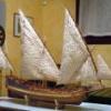
Fam Posted January 26, 2015 Author Share #30 Posted January 26, 2015 (edited) January 26th, 2015 Hi all finally, after a couple of attempts blocked by bad weather, I managed to get at the US Naval Academy Museum, in Annapolis (MD). What to say... just fantastic! I remained astonished when entered the upper floor, completely stuck with tenths of large ship models, all from the age of sails, all contemporary, all magnificient!!! Here are only 3 examples, out of about 300 pictures I took USS Syren HMS Prince Frederick, British 3rd rate 70gun, 1714 Who knows what is this?? (recognition game) What else to say, it was a pleasant sunny day perfect for visiting this completely free museum: first floor is dedicated to the history of US Navy from the Independence War to Vietnam War, going through the development of shipbuilding techniques, with lot of interactive touch-screens describing the main naval battles and the strategies in detail, lot of models, dioramas, contemporary pieces of any type. Second floor, as said above, is the Roger’s collection of contemporary models, also including several 1:1 dioramas to explain the way of living on board of these ships... Fantastic, really worth the almost 3 driving hours from where I’m staying! I really enjoyed it! Regards Fam Edited January 27, 2015 by Fam tadheus, wyz, Jack12477 and 2 others 5 Quote Joint building: Brick de 24, 1/48, jointly with Jack Aubrey (POB from Ancre plans) Works in progress: USS Constitution Cross Section, 1:93 (POF bashed from Mamoli kit) Completed models: Santìsima Trinidad, 1/90 (POB heavily modified DeAgostini kit) Genoan Pinco, 1/50 (POB bashed from Euromodel plans - my current avatar) Viking Knarr, 1/72 (POF from Dusek kit) Link to comment Share on other sites More sharing options...

Recommended Posts
Join the conversation
You can post now and register later. If you have an account, sign in now to post with your account.