Kiyoo Iizawa
-
Posts
28 -
Joined
-
Last visited
Content Type
Profiles
Forums
Gallery
Events
Everything posted by Kiyoo Iizawa
-
Hi Gerd,
I send the link to Onedrive again.
Please try to access again.
Thanks Kiyoo
-
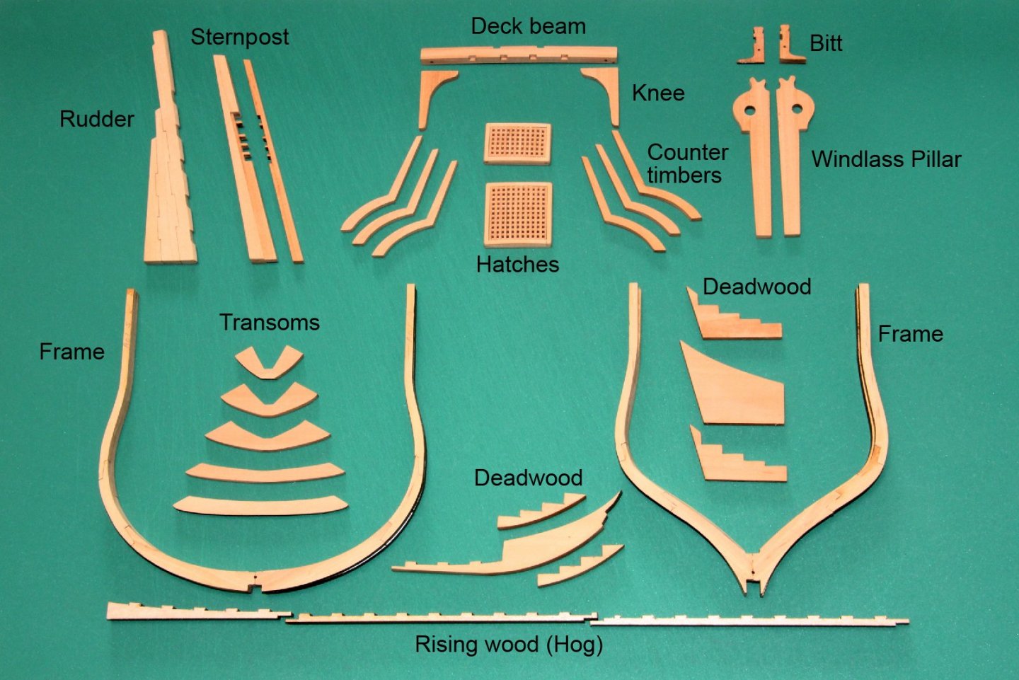
 I have good news for you all. Those of you who have gotten my procedure manual may want to try to build Granado with the attached data. I obtained the wooden sheets from Vanguard Models through a distributor in Japan, and when I approached Vanguard Models about the possibility of selling the sheets to the individuals, they graciously agreed to sell them. Of course, their business comes first, but if you are interested in obtaining the specified wooden sheets, please contact them directly. The sheets are 0.8mm and 6 types from 1 to 6mm thick, 100x500mm size pear wood sheet. If you can get them, you can use the cut pattern as I laid it out. Please try it. Kiyoo
 -
Dear Mr. Chris Watton,
Please excuse the sudden PM.
My name is Kiyoo Iizawa and I am a member of MSW forum. I am also a member of the one of Japanese Sailing ship Modelers Club.
In March of this year, I posted on the MSW forum a method I devised for scratch building of structural models, especially for beginner modelers, and received a lot of response from people around the world. I understand that post was referred to you as well. As you can see in my last post recently, my method has been confirmed as successful.
Several people who have viewed my posts have requested the manual that I provided them for reference.
The data in the manual I provided includes the design and laser-cut data for the prototype Granado, which can be used by anyone interested in building it.
For the personal laser cutting of the parts, I ordered the cutting sheets from you through Micro Craft in Japan and was able to get them successfully. The contents are pear wood sheet 0.8 mm to 6.0 mm thick, with a size of 100 x 500 mm.
The reason I am writing this email is to ask if it is okay to introduce your company in the MSW forum that people around the world can inquiring about the availability of materials from you to obtain the same board material as their design data.
Even if you do grant me permission, the terms of sale, etc., are up to you, and all I will do is simply refer viewers to introduce about the availability of the materials for build. I don't want this to be a burden or interfere with your business, and this is just an inquiry of doing introductory offer, but I hope to hear good news from you.
I will also provide you with the above stated manual and design data, if needed, for your verification.
Best Regards,
Kiyoo Iizawa
A member of Yokohama Sailing ship Modelers Club (YSMC) in Yokohama, Japan
-

Dear Mr Kiyoo Iizawa,
Thank you for your message. I have seen your work and it is very wonderful!
Of course you can mention where the materials come from, I do not mind at all. Microcraft, Mr, Konishi, is a very nice customer.
I now use 0.6 and 0.8mm wood in my own kits.
because of how popular HMS Sphinx has been, I used a lot of my stock to make kits, so I am awaiting new stock, but I can sell to individual customers.
Kindest regards,
Chris Watton
-
Hello Chris,
Thank you for your prompt response and permission to make the announcement.
If you receive any inquiries by my source referral, please respond with your own terms and condition of sale.
It would be a great pleasure if my data could be used by anyone.
Thank you again for your help.
Best Regards,
Kiyoo Iizawa
-
-
Hi Ed, Your Naiad build logs have been an invaluable resource for us to study structural modeling. It is no exaggeration to say that my system was completed by studying it. I hope my method will be a good opportunity to expand the circle of structural modeling. Thanks a lot. Kiyoo
-
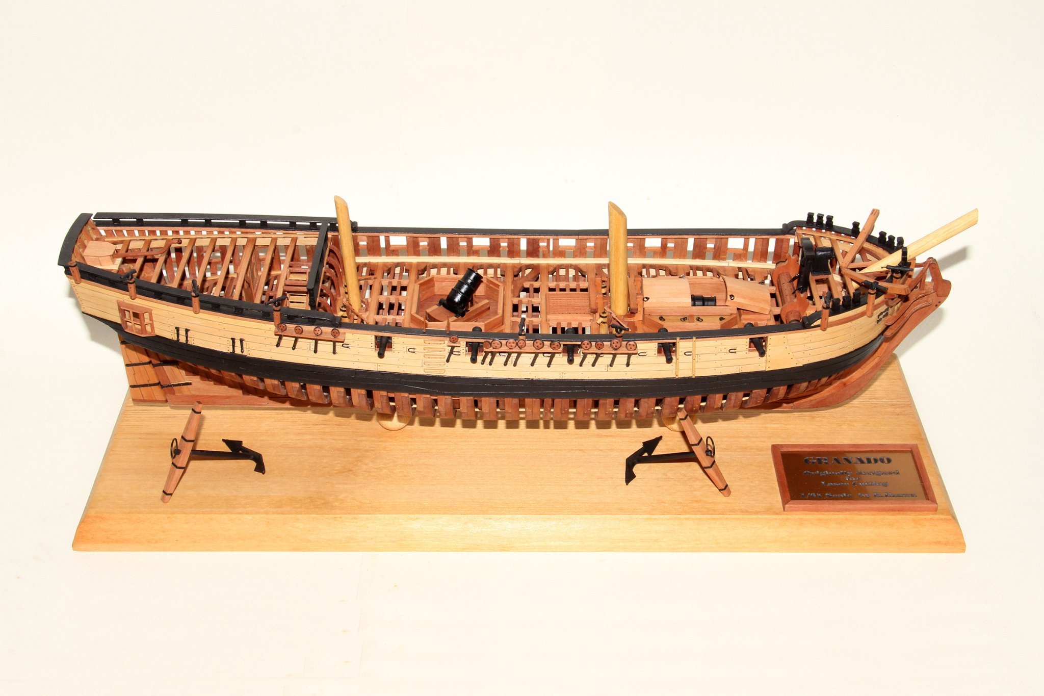
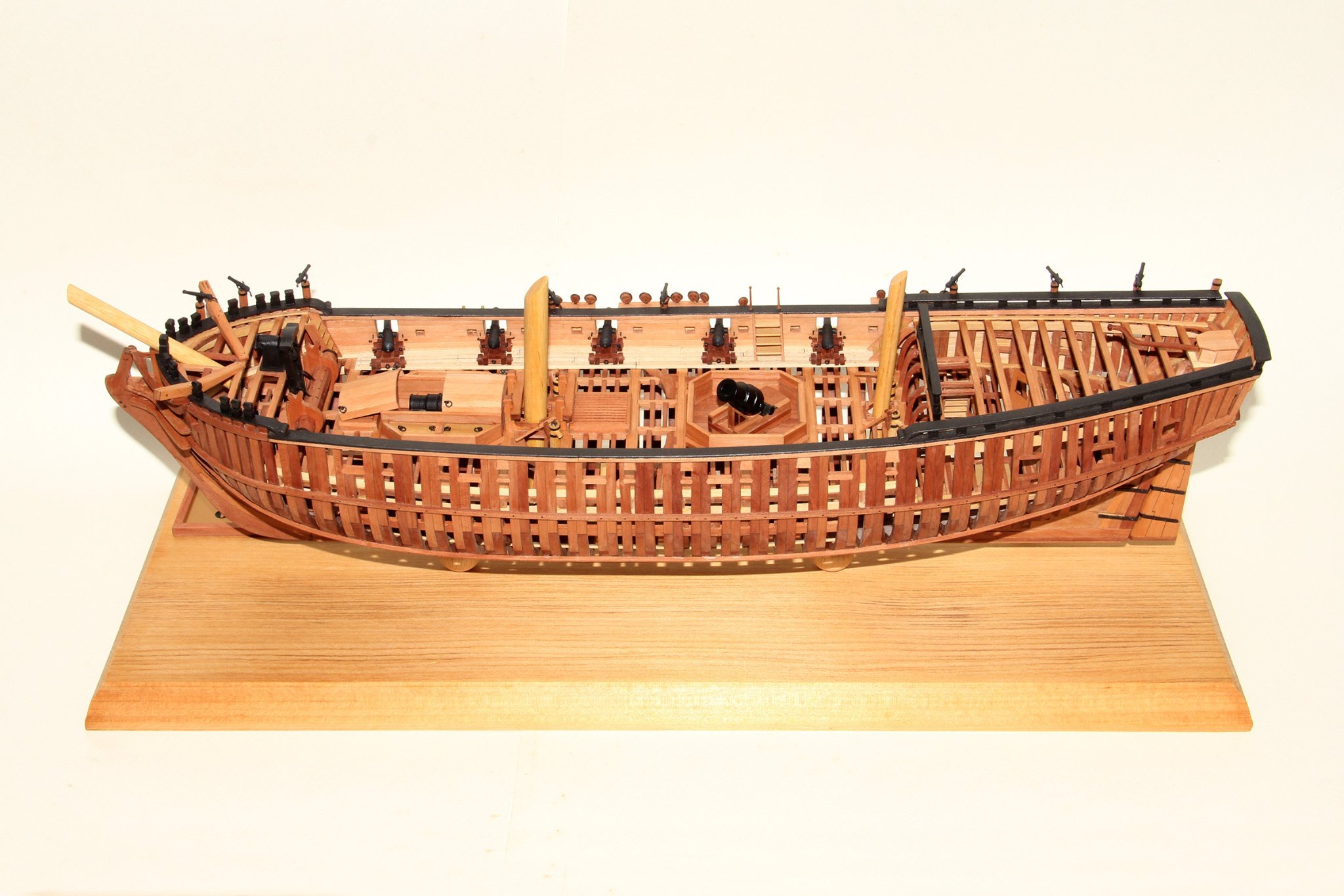
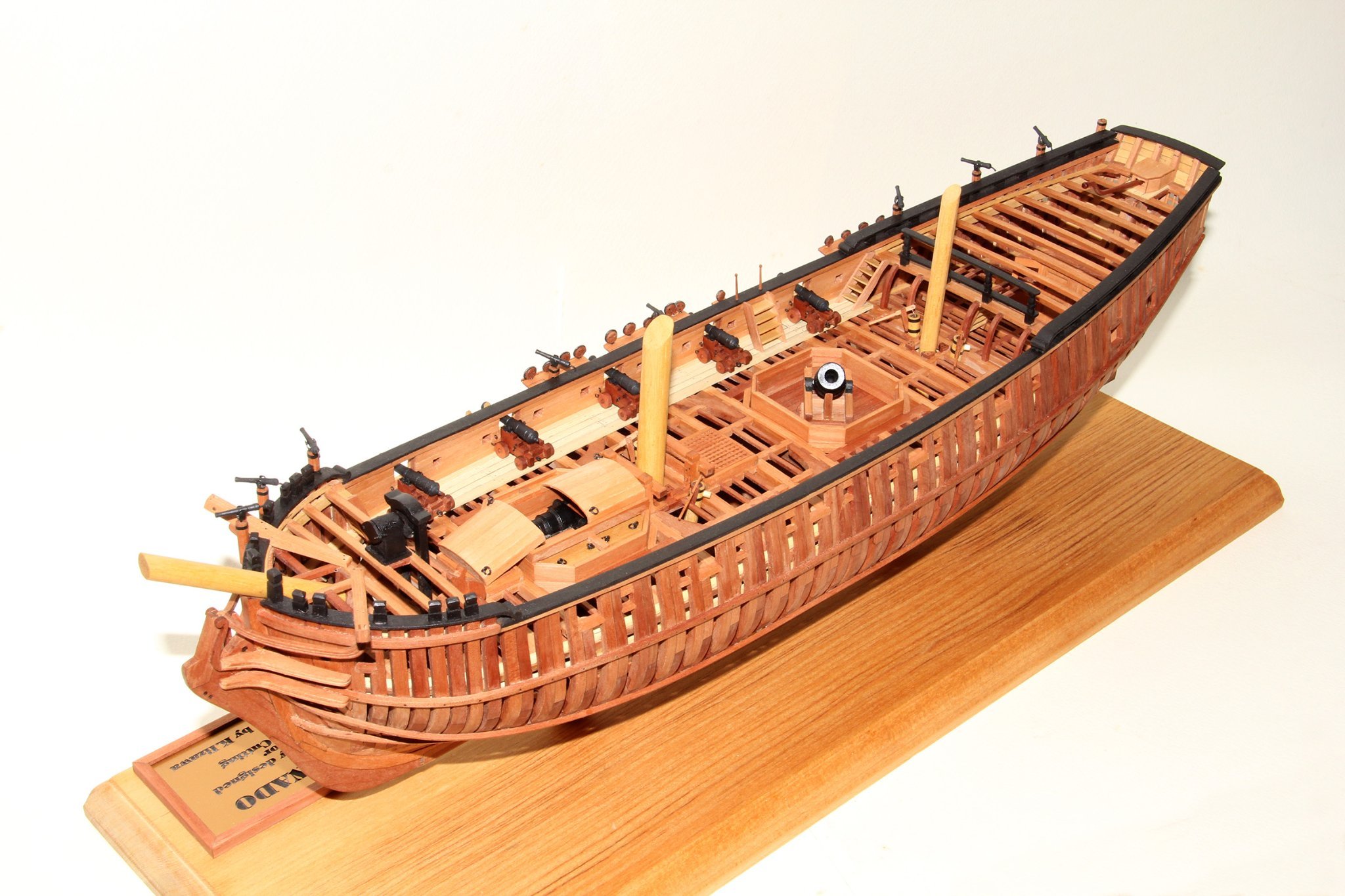
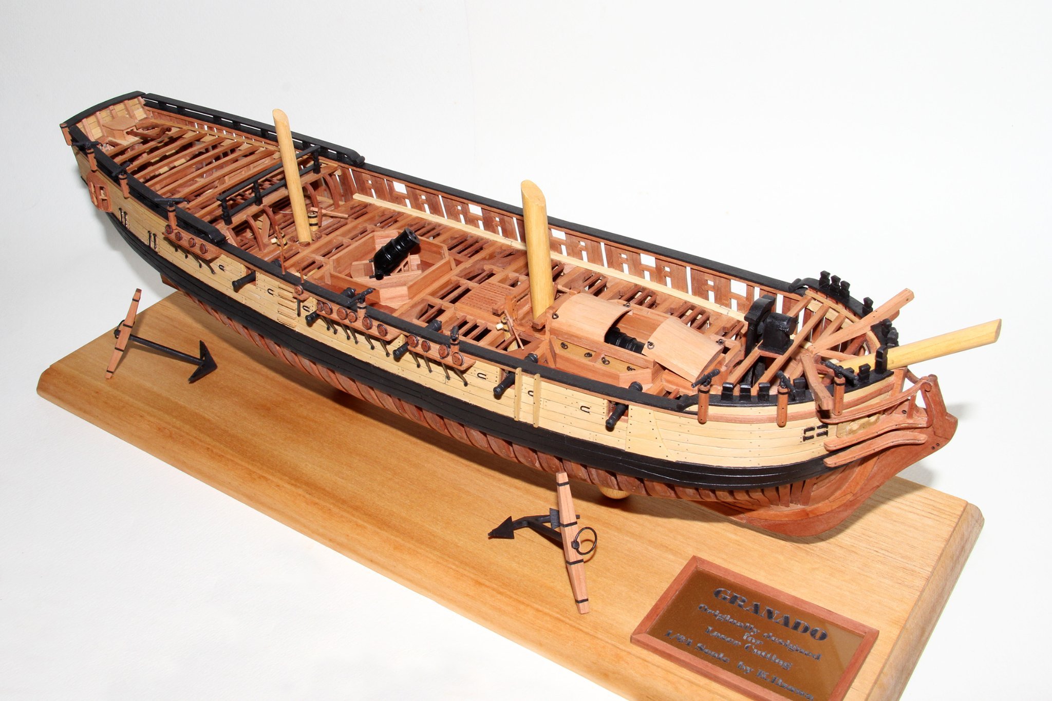
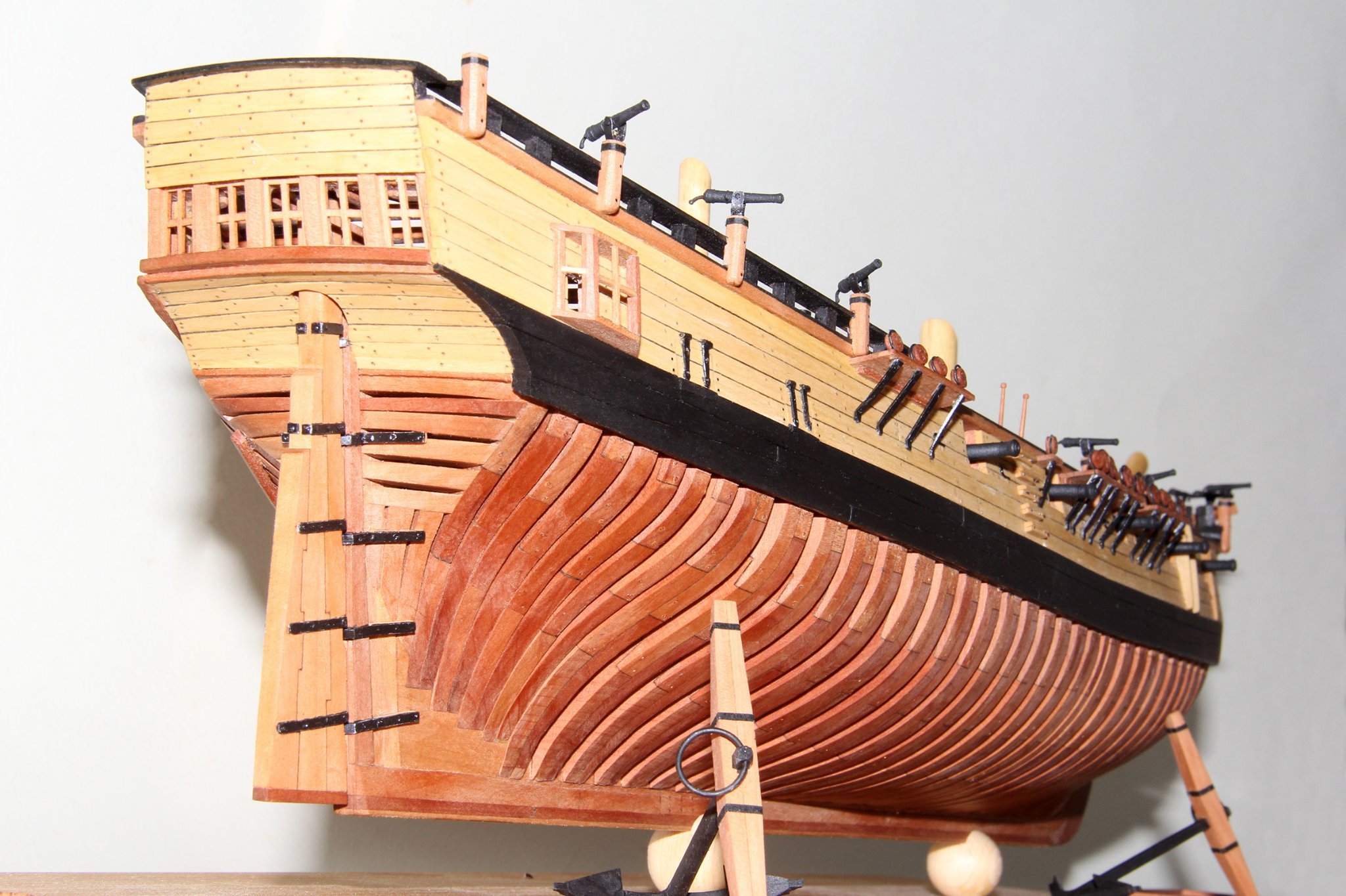
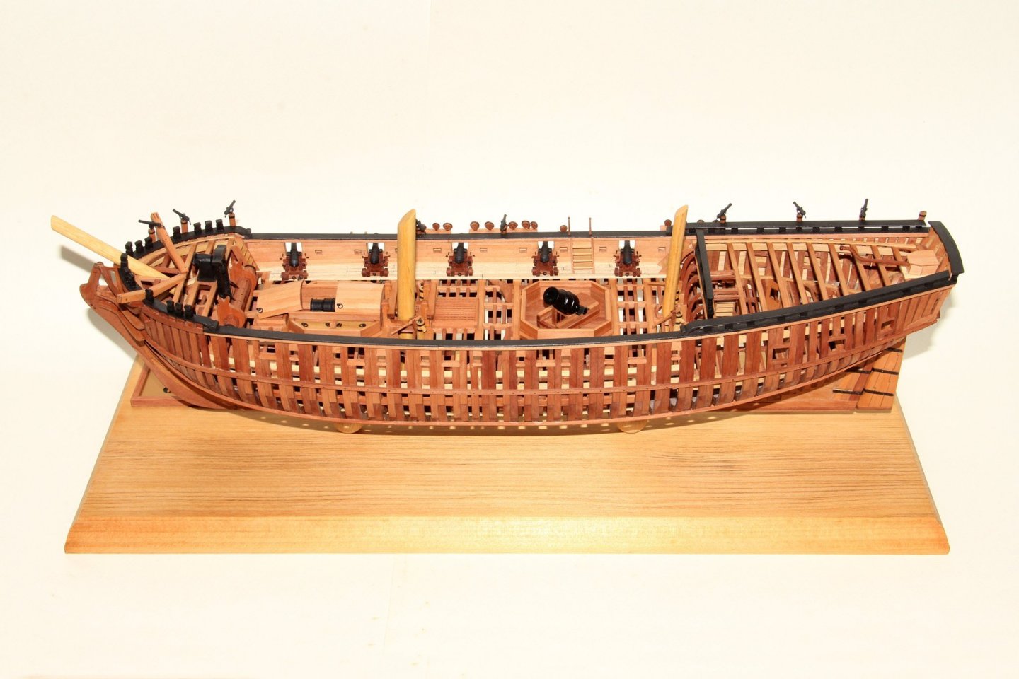
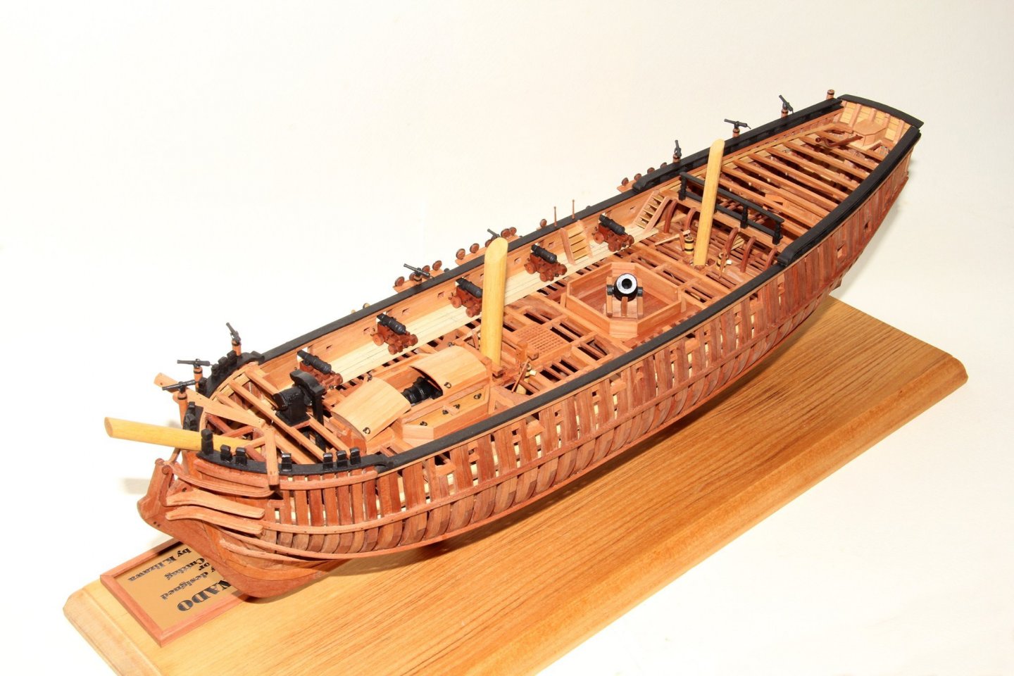
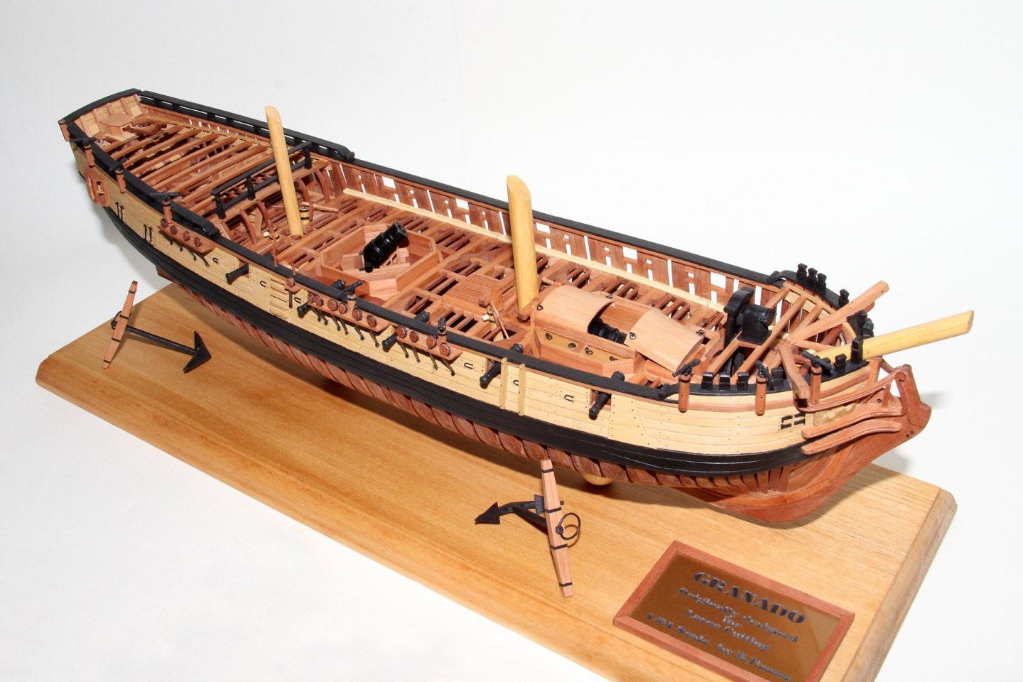
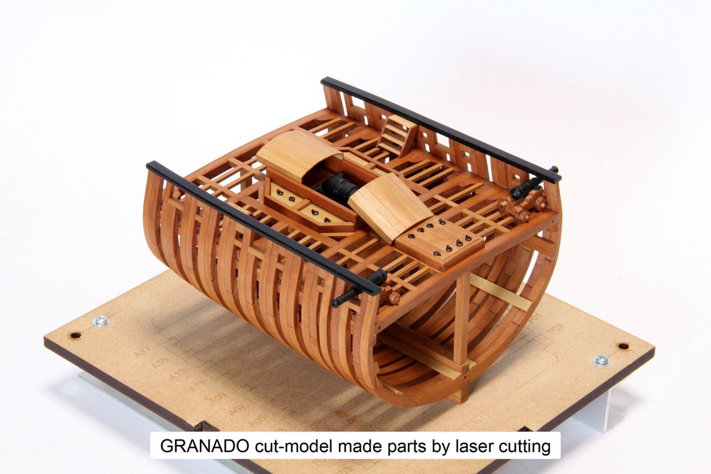
It's been a while, everyone. I have introduced here my original drafting method, but I myself did not verify the authenticity of the design yet except for a partial cross-section model. The full model requires more than four times as many parts to be assembled as the cross section, and if there are any mistakes in this method, I cannot recommend it to you. To validate this method, I completed the design of the full model in parallel with the introduction of the method, and all of its parts were laser cut, and its assembly was started. The model is GRANADO 1/64 scale. The results were more successful than I had expected, and the model was completed with more than seven hundred kinds and over 1500 parts. All were assembled exactly in place with only the laser burn-mark to be removed. Shade also can create 3D printed data, and by utilizing this, GRANADO's mortar, cannon, and swivel gun are also made in accurate scale and assembled. I think if this method spreads, even structural models will be able to be shared as an assembled set, like a bulkhead kit. I would appreciate it if anyone who has obtained a manual can let me know the impressions of this method by even PM. Thanks, Kiyoo Iizawa

- 48 replies
-
- 10
-

-
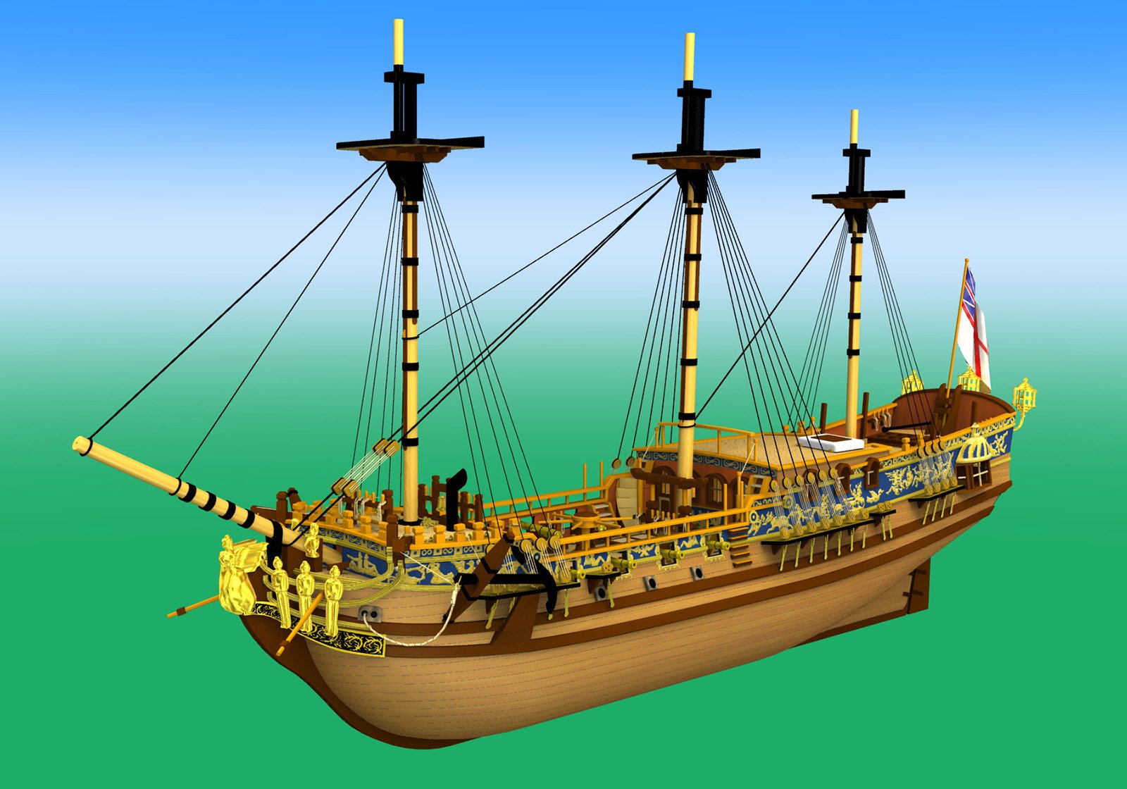
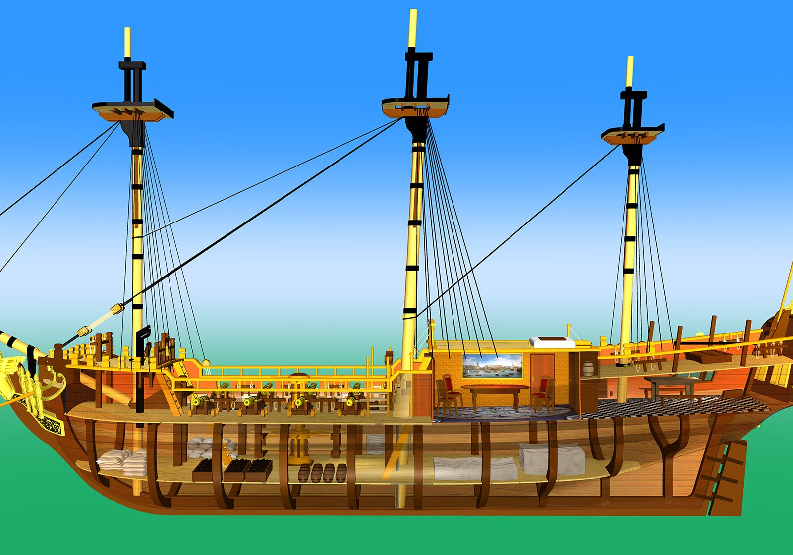
Thank you everyone, I have received many requests about the data of the procedure manual. Today, in honor of Shade, I would like to introduce you to Shade's true function: 3D graphics. Unlike most 3D graphics software, Shade can generate elegantly curved surfaces with only a few lines of drawing. One day, in addition to general Shade characteristics, a Shade enthusiast has created a rope drawing add-in for me. This allows to draw not just a straight rope shapes, but any kind of rope crawl. The first image shows the curve that the rope naturally forms, drawn with Bezier curves, and then the rope was drawn three dimensionally along that line. The next two images are of a virtual ship based on the Caroline kit that I was working on at the time (20 years ago, very poorly especially for the textures). But while I was enjoying these graphics, I discovered the method of getting curves for individual frame shapes presented here. Since then, for me, Shade has been used almost exclusively for making the frame curves, and my graphics skills have not improved at all. However thanks to this, Shade has made a great contribution to original sailing ship modeling. Kiyoo


-
Thank you everyone, for valuable comments. Making the fabrication drawings is hard barrier to scratch builder and it is very time consuming matter. One of the reasons I have summarized this method was to reproduce the free curved shape of the ship’s parts accurately, correcting and adding the information of reference drawings. This is especially useful for the free curved shape like frame and the software which have Bezier curve feature are particularly useful for that purpose. Combination of Shade and Illustrator is best for this purpose so far. Please try to take a look the manual even you only want to see how they are doing. Kiyoo
-
Everyone, Now, the procedure manual is ready to download. I have updated (as my understanding) and uploaded it to my cloud storage. When you want to get this manual, please send PM to me so that I can reach you and give download key to you. It is free download now. Many PDF and JPG files in the manual help you to look through the contents even if you do not have the specific software. Kiyoo Iizawa
- 48 replies
-
- 10
-
-
Joe, Because I am not a professional and my established method is like a one of the tips. Just using the longer documents to explain it. I like this hobby very much and if my contents seem something new, I just wished to share with those who are oriented the same hobby. Evaluation is up to you. Many thanks for the compliment. Kiyoo
-
7. Closing By verifying the effectiveness of this new method with the above-mentioned way and I could produce the final set of design drawings and laser-cutting drawings after several trials. The model design utilized the power of the software, I could add many structural parts drawings other than frame parts. In addition to further reducing the cumbersome work of conventional drawing creation, laser cutting in this method also enabled reduction of material costs and significant reduction of trimming and fairing time. In order to share this effective technique with many people, especially beginner builders who want to challenge scratch builds, I am preparing a step-by-step procedure manual " Preparation of design drawings and the new part fabrication way in structural models ". It consists of nearly 180 pages of text, over 130 picture files, and a number of design sample files. This also includes design data for GRANADO designed as a prototype and data for laser cutting. If you bookmaking the manual part like below by yourself, I am sure it will help your learning effectively. When you are going to apply this method, it may seem to you that investing in software is costly. All of the software I have actually raised here is a well-known subscription software and they are relatively higher price. Certainly, an initial investment in case it is done by an individual may become nearly equivalent to a power tool to buy. However, the design and fabrication benefits that this method provides are immeasurable, including the reduction of creation time. Moreover, once these data have been made, a lot of people can share them like I am doing now. Thus the total cost per person can be comprehensively reduced. I have designed more than ten models frame data ever by using old version of this method and so far, it is used by many people in Japan. Creating the beautiful hull curved surfaces and the part drawings that make them up is just as fun as building a model. In the last, I can say that by mastering this method, You can design your own ship models and prepare the necessary drawings with the many flexibility. You can accurately cut the necessary parts by yourself within a noticeably short time! These are a lot of time saving at the preparation period and finally you can concentrate to your scratch model building! I am now going to store the procedure manual files on the cloud storage etc. so that it can be shared with the MSW member who want to learn the procedure and/or use this method. It is not a commercial purpose. Please send PM to me for the proposal. Then I give the key to download them. I hope this action will not be violate the MSW rules. As I am refreshing the sentences of the manual now, please allow that it may take a while to upload them. Thank you for reading through the introduction of my method and I hope that this method will enable many people to challenge scratch building. Kiyoo Iizawa A member of Yokohama Sailing ship Modelers Club (YSMC) in Yokohama, Japan

- 48 replies
-
- 15
-
-

-
Joe, Thanks for the valuable comment. It would be hearty if the MSW staff could help. I've even thought of ways like you but I say it is not mandatory matters to the member. I will try to contact the person you recommended. Kiyoo
-
Thanks for the evaluation druxey, So far, countermeasures are effectively working in my prototype. Kiyoo
-
Joe, Thank you for the comparison between CNC and laser. They are each have the advantages and the disadvantages. But any of the way, I am sure they become strong aid to make the parts for scratch building, especially the case to cut the uneven curved shape. There are not many restrictions on the feeds and speeds in laser cutting. That may be due to the extremely small thickness of the blade (the diameter of the laser). And for now, Illustrator is responding well to the changes and corrections the data for cutting. Yes, “char and the slope of the cut” is a relatively bigger issues in laser cutting so far. Although I provide some countermeasure for them, I appreciate if anyone find more practical way to solve. Everyone, My brief introduction will be closed soon. So, I am thinking now to freely provide the procedure manual of my method to those who wish to learn and use my method. Does anyone can advise the data storage method so that only the MSW member can access to there. Kiyoo
-
Hi Jooe, thank you for your comment. I also have been encouraged of the CNC by Bob Hunt’s Kingfisher kit. But at that time I never thought that I can personally handle either CNC or laser cut. But recently, I found that laser cutting fills my all requirement which is that I can prepare the data using my existing properties and also can operate the machine by myself. That is the reason so far, I selected laser cut rather than CNC. I think CNC may also become familiar soon to individuals same as laser cut. I propose the way of open public of my procedure manual in next post. Kiyoo
-
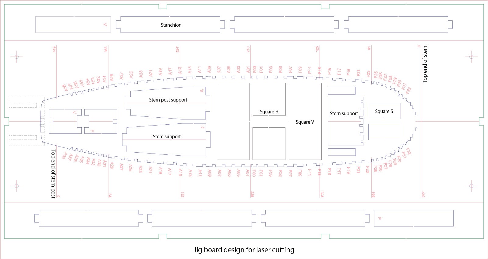
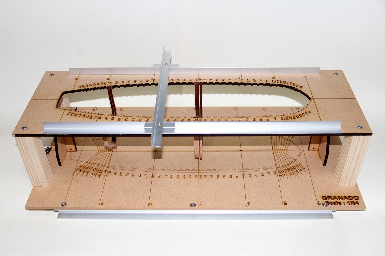
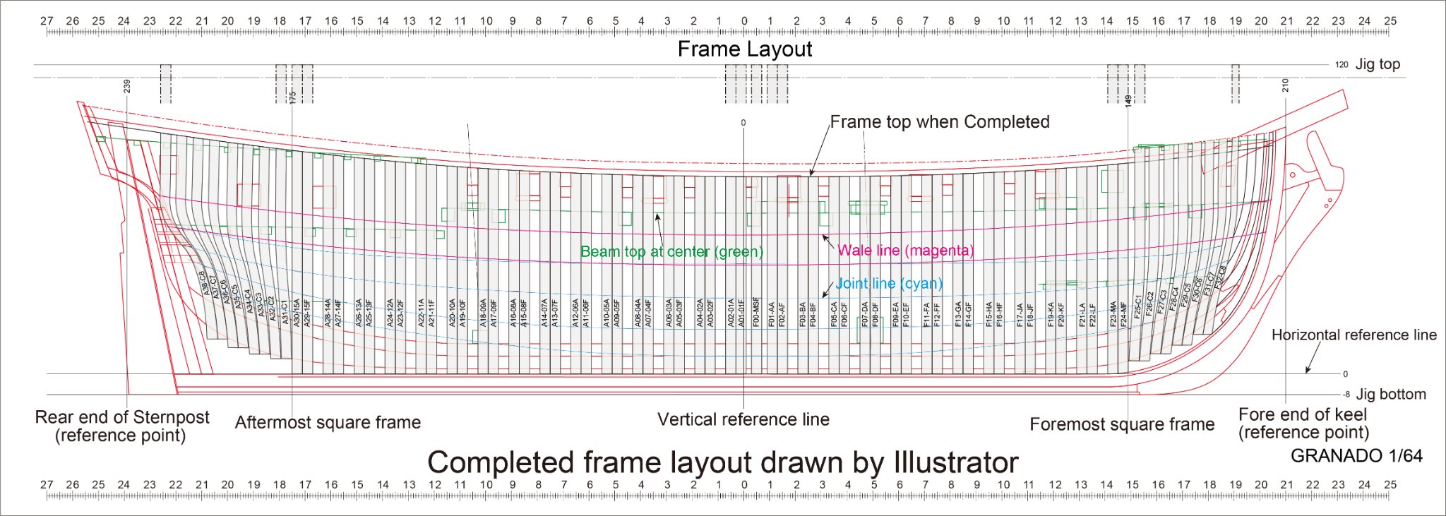
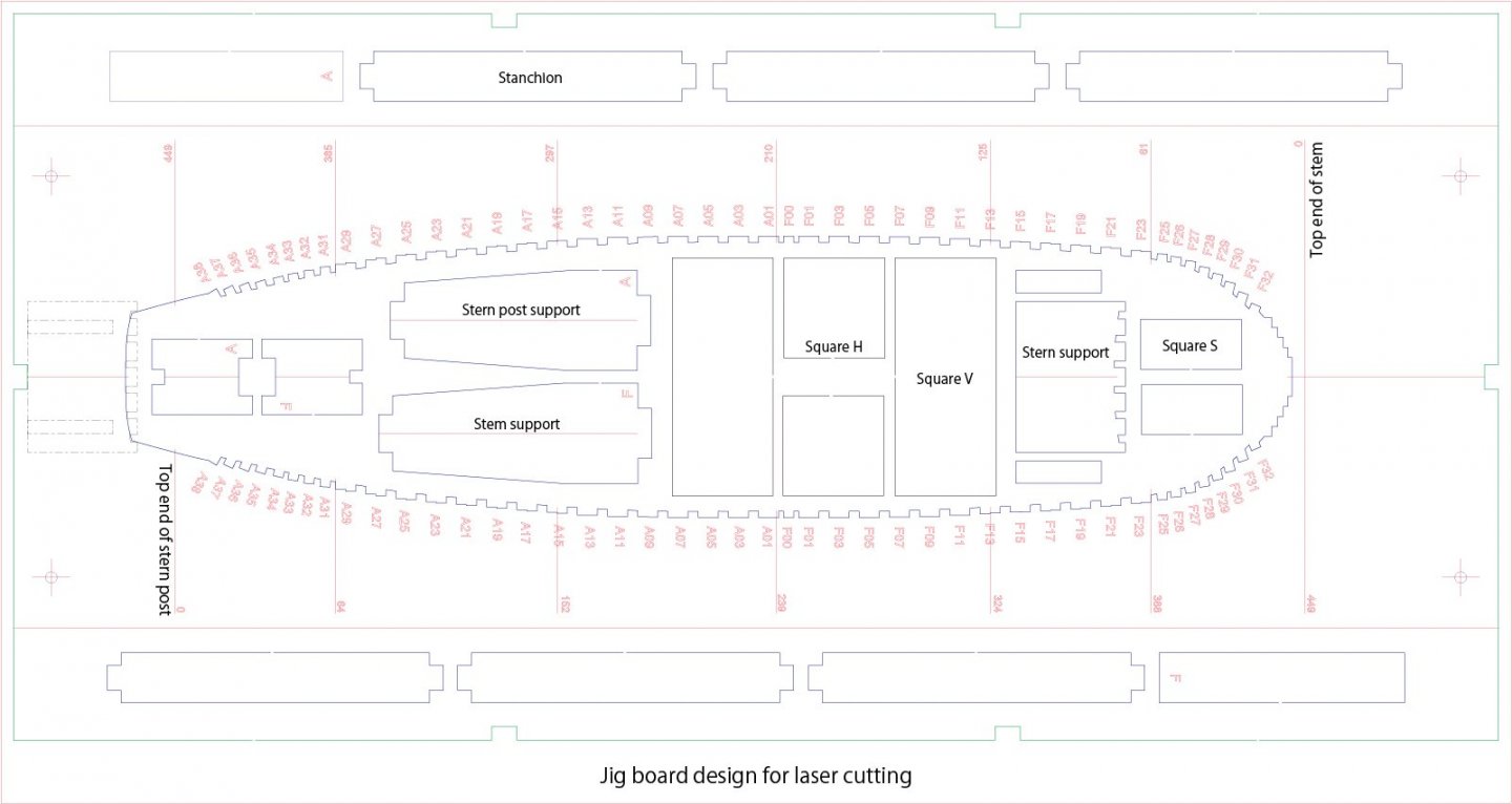
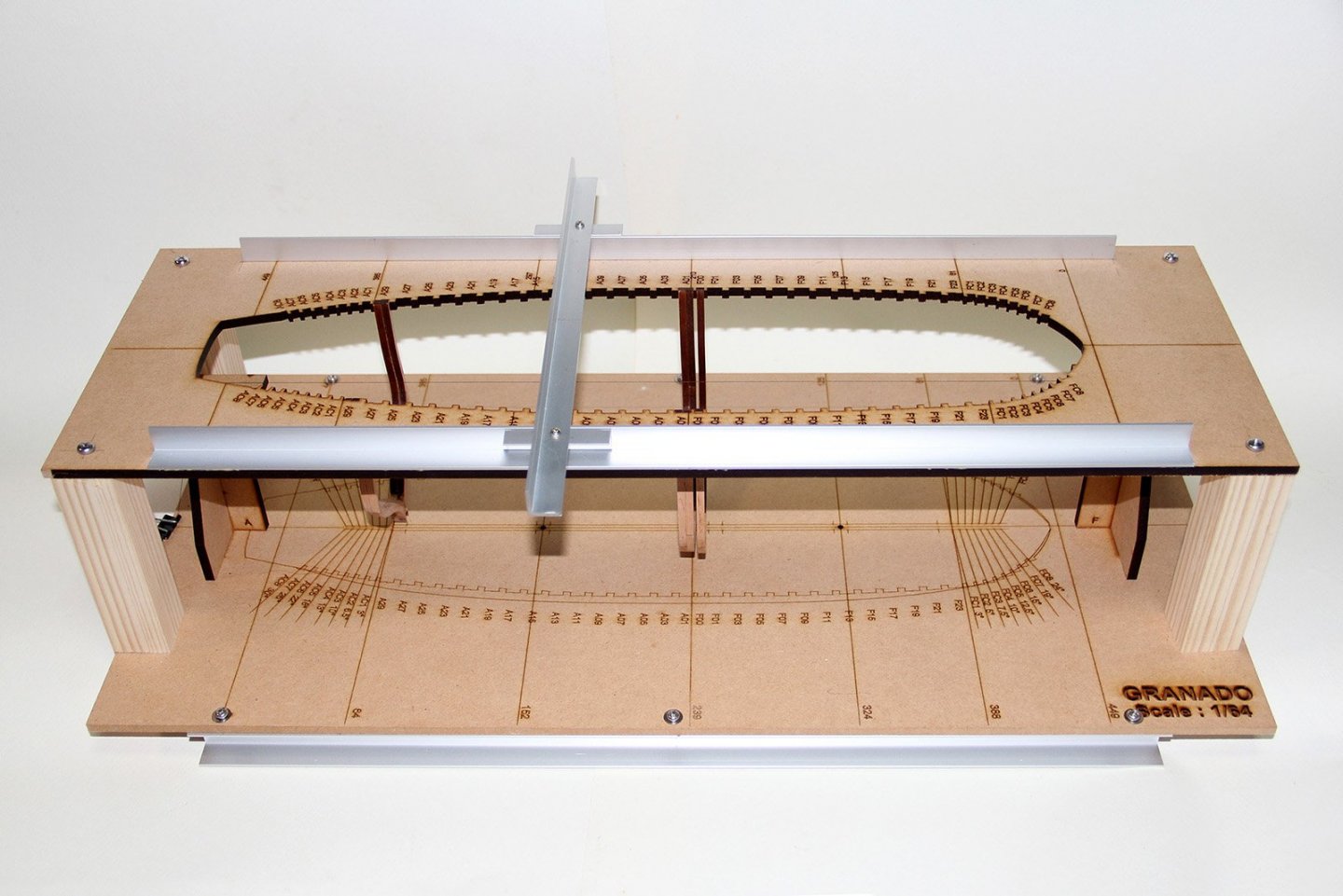
6. Deployment to assembly jigs The application of laser cutting techniques can be applied not only to accurate the parts, but also to the creation of jigs that ensures assembly accuracy during assembly. In the assembly of the framed structure model, it is necessary to assemble a large number of parts with accurate alignment, but it was also found that the jig plate for positioning which becomes the guide can be easily fabricated with laser cut using the several assembly drawings data. It is possible to design the jig incorporate with the necessary ideas such as reproducing the notch shape to accurately holding the frame top, reproduction of the angle of the cant frame, the addition of various reference lines and so on. And because they can be easily applied to the jig configuration, the assembly of the hull can be made revolutionarily easier. After several attempts, the latest design is applying the following features: 1) Cutout of the outer periphery of the jig plate In the beginning, the outer periphery of wood sheet was used as it is. But since there is a possibility that the center position misaligns at the time of setting of wood sheet to the machine, it was finally decided to cut out the outer peripheral portion with a certain dimensions. By this, relation between outer frame and center line of the jig plates is always kept. Also, since it can be possible to accurately align the relative position of the stanchion and the fixing holes, it become easy to assemble the jig. 2) Preparation of the stanchions In the beginning, it was assumed that the fixing stanchion of the upper and lower jig plate will be prepared by the builder oneself, and only the drilling position for fixing was displayed on design drawings. However, since the jig accuracy may collapse by the stanchion length and the accuracy of drilling hole, it was decided to prepare these stanchions as one of the elements of the cutting data. In addition, these were made to be able to put out the position accuracy even if only by fitting each other. At our trial stage, only by inserting the six stanchions in each position, the relative position of the upper and lower plate can be secured without gluing, it seems enough for the assembly of the frame. If you are concerned about the looseness, it becomes more stable if you fix the front and rear of the jig simply with a rubber band or a string. I am only using masking tape to temporarily fix the stanchion and the board. The reason for a recommend that not fixing the stanchion in this way is to avoid that some of the stanchions disturbs the action at the time of such measurement and processing of the hull outer surface. Also, it enables to remove hull from jig for easier fairing and sanding of the entire hull. 3) Clarification of the reference position The hull design has taken the method of dividing the midship position back and forth as zero position based on the contemporary design standards of the ship, but it was found that it is difficult to measure in actual assembly of the model. Therefore the reference position on the assembly was changed to start from the hull ends, it was to display the representative dimensions from there on the jig plate by setting the zero position at both ends so that accurate measurement can be made from either end. The specific zero position is the fore top end of the stem and the aft top end of the sternpost. The hull (keel) support on front and rear the jig is also supported in this position. 4) Proper reinforcement and measurement guide Although concept of the jig is well providing sufficient usage as mentioned above, it is recommended to attach a foot of aluminum channel as reinforcement. There is also an option to provide rails to guide the instrument for measuring the inside of the hull from the top. In the process of prototype verification, this jig demonstrated great power in positioning the parts during assembly and in various measurements. To be continued, Kiyoo
-
Thanks PietFriet, Because the benefits of laser cutting are highly efficient for scratch building, I thought that to solve some issues of laser cutting will be extremely useful. So while verifying this method with several colleagues of the association, we recognized the issues and taken countermeasures to them. I am still on the way of improving/updating this method. Kiyoo
-
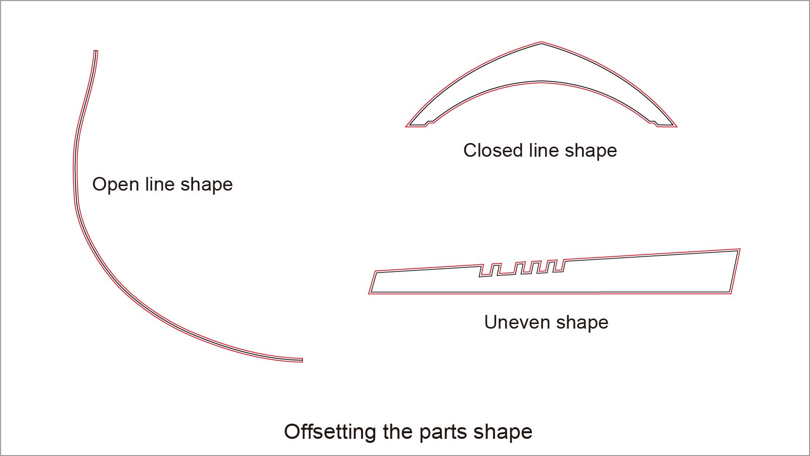
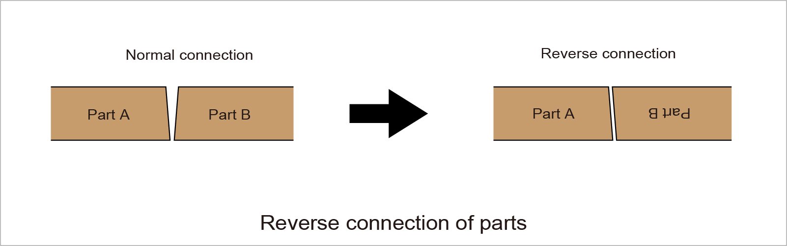
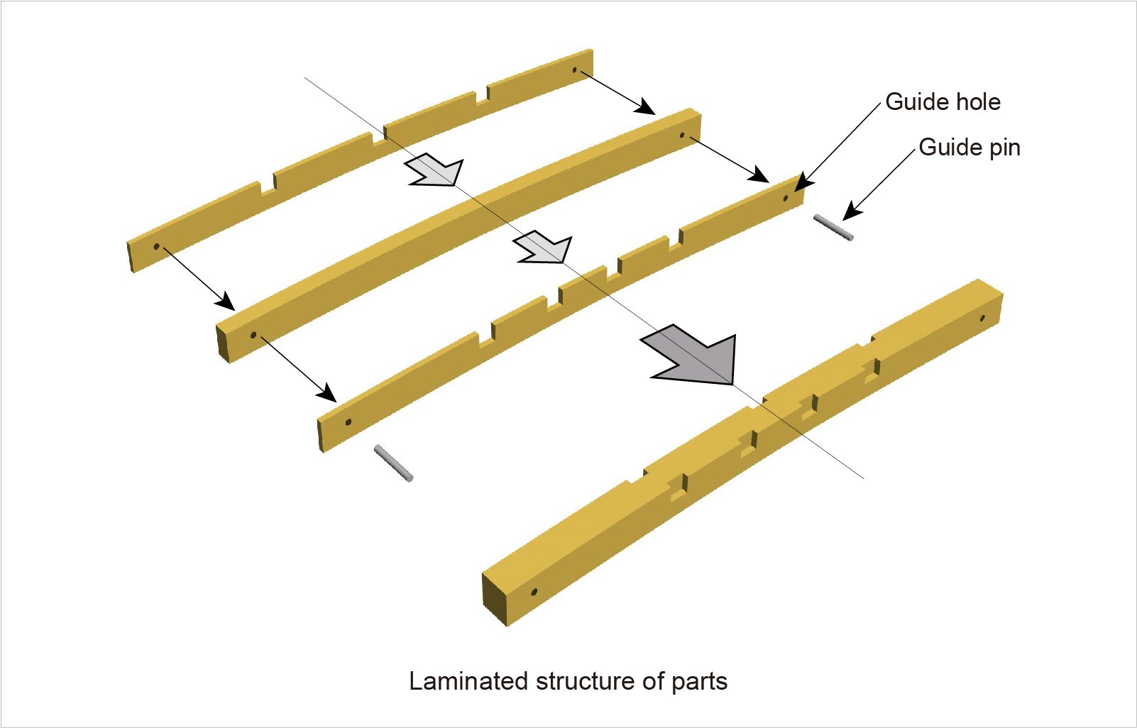
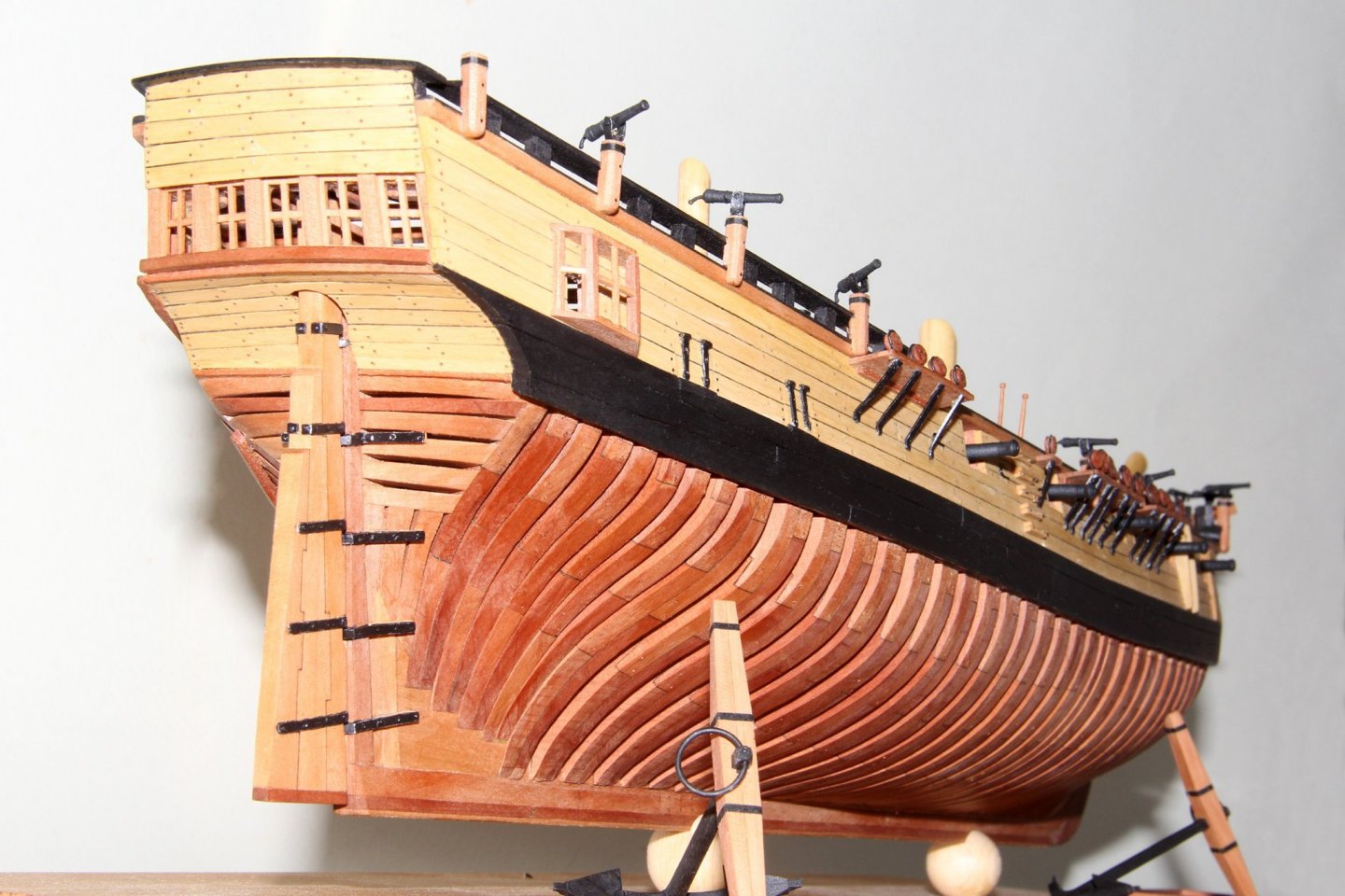
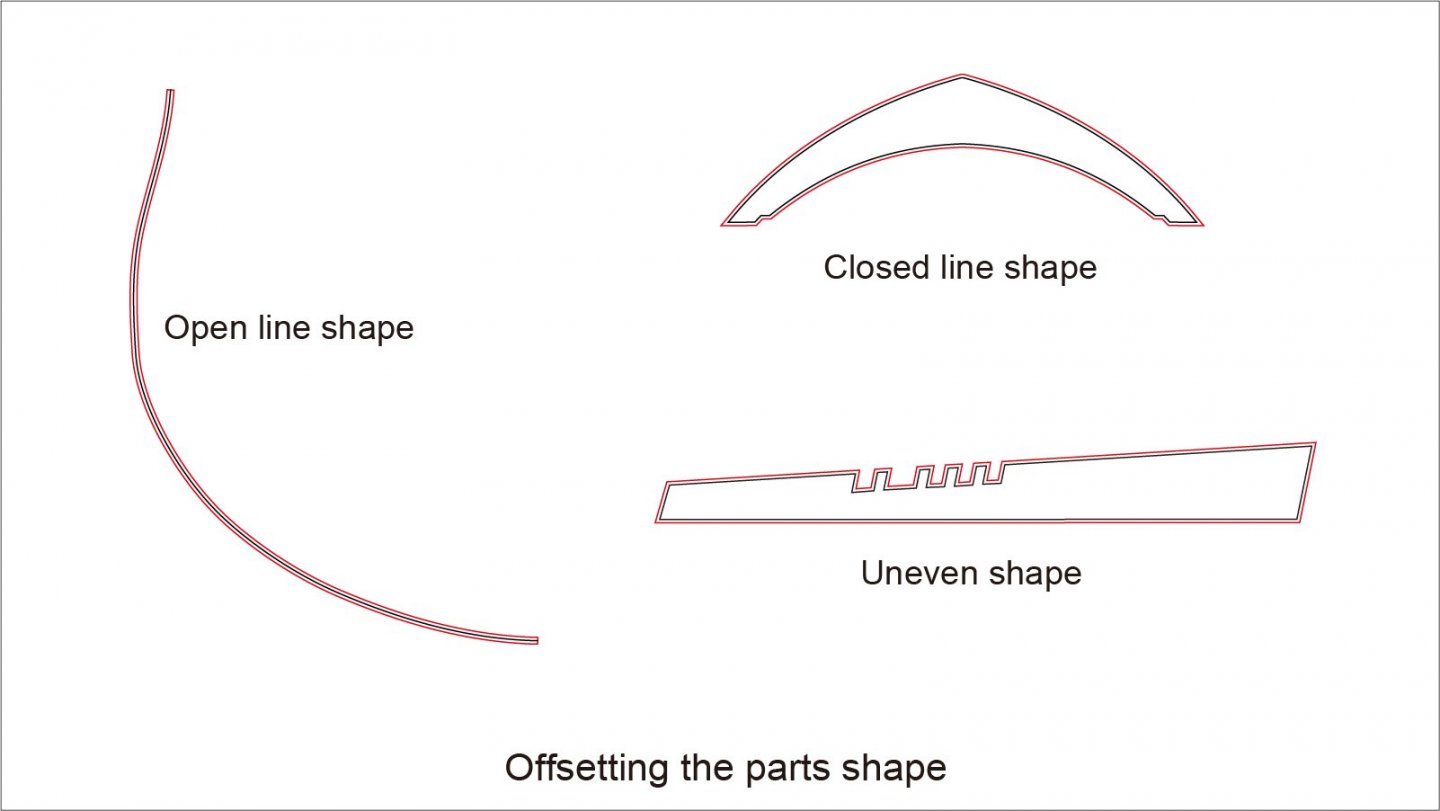
5. Summary of Drawing Correction for Laser Cutting This section is an example of drawing correction for laser cutting that I have compiled through the building of prototypes. In order to summarize the drawing correction, I referred to some tips in this Forum etc. 1) Offsetting or Expanding of the parts outline Specifically, each futtock in the prototype is offset with 0.3mm margin on Illustrator data. Since the outer shape is supposed to be shrunk by approximately 0.1mm by laser, and further margin of 0.2mm is added as sanding fee for removing the burn marks. At fore and aft end frames, much more bevels will be required, but keep in mind that the minimum sanding portion is about 0.2 mm (do not sanding too much). On the other hand, burn mark at the end of each futtock is left so as to it simulates tar caulking of actual ship building when glued together. Above all, this is the adhesive part, so there is also the purpose of not breaking the parallelism of the faces of each other. In Illustrator, it is easy to add correction in accordance with the site of the shape by function called "Offset Path". Other parts other than the frame are also offset in the same way, but unlike the frame, it is uniformly offset on the entire outline. The adding amount is changed according to the thickness and the shape, it is displayed in the Layout drawings and Offset drawings for each component. Note: I am not sure because not try yet, but if you arrange the offset value according to the situation, may be you can create the data which can also be used for CNC cutting. 2) Alternating the reverse junction of futtocks As mentioned in the previous paragraph, since the cut surface is not at right angles especially in the case of thick wood material, the futtocks of each frame set are joined alternately reversing front and back surface of the part. Therefore some of the futtock are drawn by flipping the outline. Specifically, the second futtock and the third futtock, and part of the cant frame are drawn in flipped condition. These are easily identifiable because it is displayed by also the flipped ID number in the Layout drawings. In the actual assembling and gluing, parts are firstly lay the parts on assembling drawing according to the ID, flipped part again if the ID is reversing then glued them together. This method makes it possible to get much stronger gluing strength and flatting the surface. Since the scarf length of both ends has also been different, there is not a risk of misassembling the top and bottom, but please be careful about the assembly of the frame. The method of the front and back alternating joints are also applied when combining several members in one component such as knee-of-the-head and rudder. They are easily identifiable because of they are flipping ID numbers as well in Layout drawings. 3) Odd number frames The odd number frame starting from the first futtock (not from floor timber) is flipped not only intermediate futtocks but also whole frame set of the opposite broadside because lower end of each frame set will be glued together. Therefore, assemble two sets of either port or starboard frame, then flip either one so as to lower end of first futtock is joined firmly together. In the Layout drawings, it is drawn by two sets of futtock ID "s" side (aft frames) and "p" side (fore frames) respectively. It is not a mistake, so do not confused. 4) Guide hole On the center portion of the frame (portion spanning the keel) and both top end of each top timber (actually at vertical extension part) is provided with 1mm hole for alignment the frames each other for double frame assembly. These holes will also be changed their diameter by laser cutting. Therefore, in the case of center hole of the odd frame, it will be re-drilled to a predetermined diameter (1 mm) with pin vices since it seems that the pore diameter is reduced after gluing both lower ends of first futtock. On the other hand, hole of the even number frame (frame with floor timber) and holes of both the top timber have been previously set the pore size smaller, so that it become a substantially predetermined diameter by laser cutting. During the assembly of the double frame, builder can easily align the inter-positioning by inserting a 1mm brass rod into these three guide holes. 5) Laminate structure of beams, etc. The deck beam has a blind notch to hold the carling on both sides, such a shape cannot be easily produced by laser cutting. Therefore, one beam has consisted of a structure of three layers. They are the center portion without the notch and both sides with the thickness of notch depth. Further, guide holes of the same idea as the section 4) are provided on both ends. This holes are become invisible by the knee after assembly. This lamination method is also applied to the assembly of the bitts and the catheads which have hollow holes their inside. Lamination idea is based on Bob Hunt's Kingfisher kit. 6) Fitting with assembly jigs As described above, the portions that can be dealt with by the joints between the parts and the like are being corrected, but some other parts are not. To ensure the assembly accuracy, portion where it is tight need to be sanded a little bit. To be continued, Kiyoo


- 48 replies
-
- 11
-
-
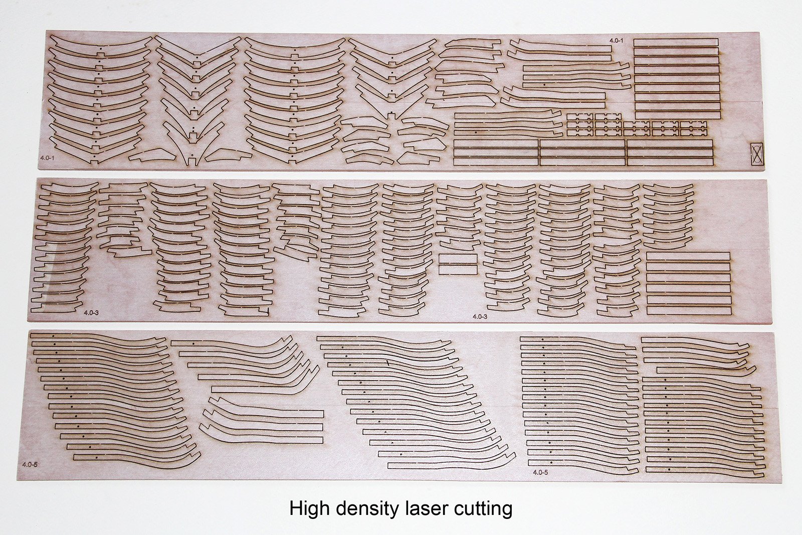
4. Making of data using the new method Laser cutting have a great advantage in accuracy and speed, but on the other hand, it also has some weaknesses that cannot be seen in other cutting methods. This method has also established various workarounds to solve these weaknesses and enable the application of laser cutting techniques for framed structure model building. Let us look at the characteristics of laser cuts, including the workarounds. 1) Since it is possible to faithfully cut the shape data at a very thin cutting width (0.1 to 0.2 mm) by irradiation of the laser beam, the time of fairing (grinding and sanding) of the model can be greatly shortened. Further, the thickness of the blade (laser beam diameter) also improves the material yield, it is possible to place the parts spacing close together, it is possible to reduce the required material to a maximum of about half as compared to cutting with manual or electric tools. 2) Cutting speed is extremely fast, the parts cut of one frame is within a total of about 30 seconds. For instance, in case of 1/64 GRANADO class ship model which cuts nearly 1500 pieces of parts , you can work within a rental time of 5 to 7 hours even if you include the setup time. 3) Since laser cutting machine can treat native format data drawn by Adobe Illustrator, there is basically not required to convert and/or recreate the data. Note : Depending on the laser machine, many formats are also available, .cdr .dxf .pdf and so on. 4) The processing function provide options such as cutout, semi-thick cut, and carving, it is possible to distinguish the processing by changing the line weight and color of each line data. 5) Since processing is a method of burning through the material by laser, a black burn mark on the cut surface is inevitable (in the case of wood). Parts such as frame, if it is exposed to the model surface, it is necessary to remove the burn marks cleanly. But whole shape of the parts will become reduction in size by sanding burn marks unless expanding the shape. Since Illustrator has a function of offsetting the outline without deforming the whole shape, it is possible to avoid this weakness by correcting the shape using this functionality. 6) Because of characteristic nature of laser power to become decrease as proceed forward, the cutting surface is no longer vertical as a result. As a result, glue strength is weakened in such a case of joining the cut parts together because of generating triangular void between parts. As a workaround, cut the shape by flipping one of the adjacent parts, it is possible to align the inclination of the cut surface by applying a technique of joining by flipping it again during assembly and the gluing surface is possible to ensure the parallel. Please refer to section 5 for these specific methods. 7) As one of the drawbacks at the present time, there is an issue that wood sheet of fixed size is not easily available in Japan. There were several wood material suppliers in the United States, and it was possible to procure with a fixed size, but recently, some of suppliers began same business also in Japan. The CD data is laid out on a wood sheet size of 500mmx100mm based on this expectation. For other sizes, it is necessary to re-layout according to the wood sheet size. Re-layout is not a difficult task, but you need to operate the software by yourself or please feel free to ask me to lay it out. Laser cut parts, removed from the sheet, sub assembled and roughly faired. To be continued, Kiyoo
-
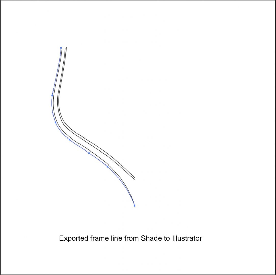
Terry, Thank you for checking with Delftship. Shade - DXF export - TurboCAD produces the same result. I also use CorelDRAW, so I know the characteristics of node (control point) and it is useful. Does gazillion nodes mean too many nodes? If so, that’s right, DXF format will have much more nodes than I made for some reason, and if you reduce the nodes number without care, you will not be able to restore the original curve when you smooth it out. This is one of the reasons why CorelDRAW and TurboCAD are not available directly at this time. We seem to need a little more study around here. By the way, the number of nodes of the frame curve I created by Shade is 6 to 7 including both line end, and in the case of Illustrator, you can export exactly the same with that number. Of course, there is no need to modify the shape at all. Next figure shows the one I exported from Shade to Illustrator. Small squares on the line are nodes (anchor point) just for reference. Thanks, Kiyoo
-
2. Configuration of the new method This method integrates 3D graphics software, 2D graphics software and laser cutting machine into one workflow to produce accurate design data in a short time. It can also perform the part processing at high speed without compromising the accuracy of the original design data. The software used for this method are software "Shade 3D" in Japan for 3D modeling and "Adobe Illustrator" for 2D data compilation. In the past, 2D software has been using "CorelDRAW", and there is also a laser processing machine that can cope with CorelDRAW. However, I have changed to use the Illustrator as a standard because the great advantage of direct data transfer between software. Illustrator also has a wealth of effective operation functions, such as data correction to compensate for the weaknesses of laser cutting, resulting in a shortening of machining data creation time. Shade https://shade3d.jp/en/ 3D graphics software in Japan. English interface is available. Recommends Standard grade and above. Illustrator https://www.adobe.com/ Famous 2D drawing software in the world. Language can be switched according to the system language. Even if you are using the CorelDRAW, if you add some conversion processing in CorelDRAW, you will be able to pass it through to the laser cutting machine, so please try it too. 3. Features of the new method This method has the following features: 1) The 3D software "Shade" allows you to draw smooth and accurate three-dimensional hull shapes from the Body Plan data of the ship you intend to building. 2) The hull shape can then be generated the outlines of each frame by slicing the shape (drag a little bit on the any of lateral line) at the desired position. Since the combination of Shade-Illustrator can output these outlines data directly as Illustrator data, redrawing (tracing) of the outline, that was needed at the time of CorelDRAW, become not necessary. Note: In the recent version of CorelDraw, It can become import the Illustrator data. So, once you export data from Shade as Illustrator data, you may be possible to import it into CorelDraw. In my case, sometimes it was unstable but it is meaningful to try. Also, Shade can export line data with DXF format which is the common for 2D CAD. But unfortunately at the present, it is exported as only folded line and is not curved line. I am expecting further updating of these software. 3) Not only the line shapes, since the dimensions and coordinate information can also be shared, it is possible to laid out each part accurately to draw assembly drawings. Furthermore, it is also possible to produce an undrawn part drawings from the assembly drawings. Since all the shape dimensions can be controlled by numerical input, the drawing accuracy is the same as CAD. 4) Laser cutting by this data is exactly accurate and fast compared to processing by conventional band saws. Since the parts spacing can be reduced to less than 1mm so material cutting efficiency (yield) is greatly improved. The actual processing can be cut all frame parts (Futtocks) for one ship within only a few hours. 5) In recent years, it is possible to rent a laser cutting machines at a DIY workshop and makerspace with a low cost so investing the expensive power tools may not be necessary. To be continued, Kiyoo
-
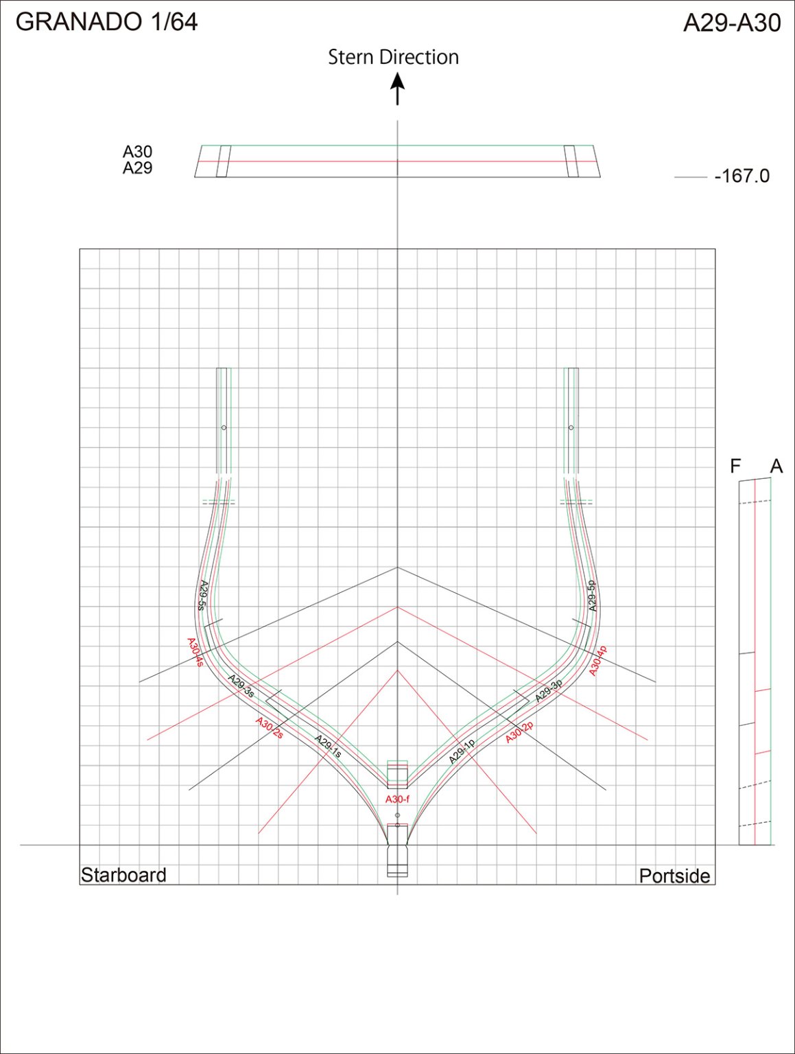
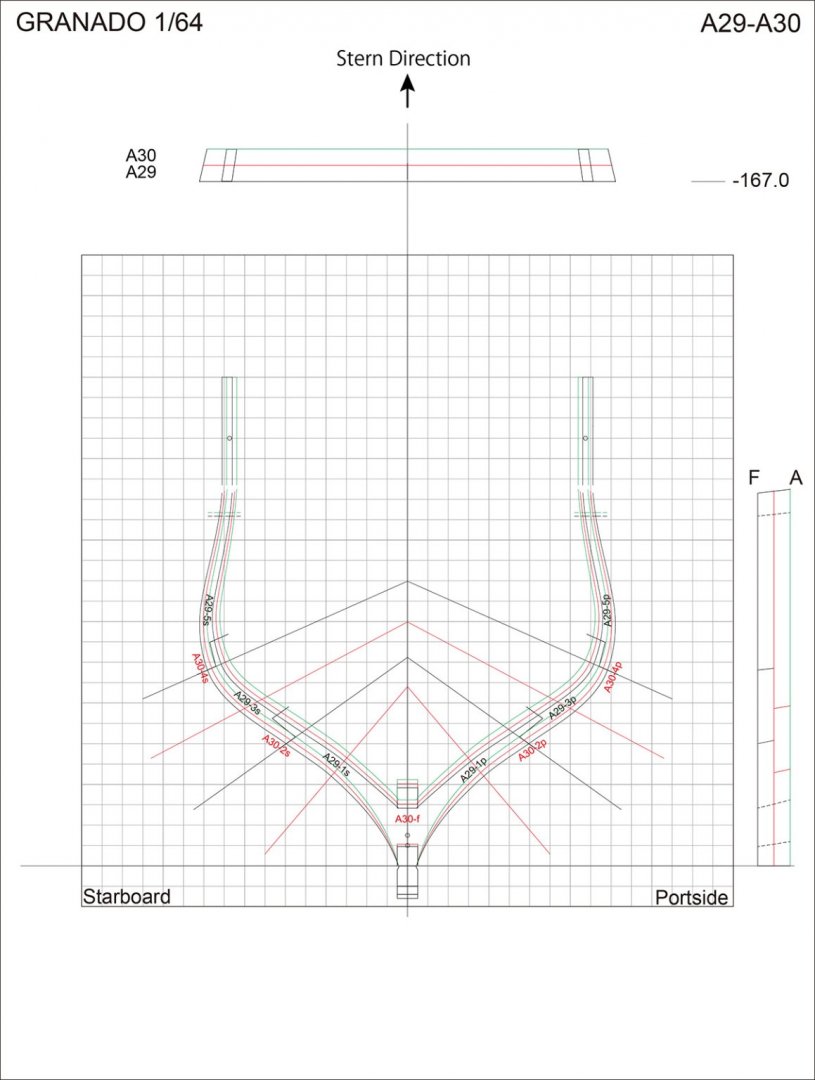
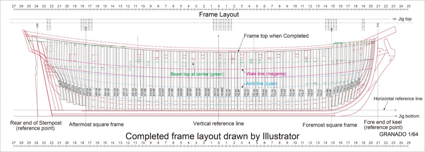
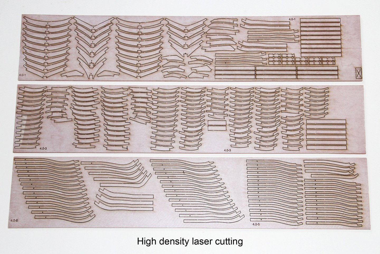
Although it is a unique method to use 3D graphics software for generating the complex line shapes of drawings, in addition, 2D graphics software that provides the Bezier curve function is better for ship designing which have many irregular curved shapes. The following two figures are various assembly drawings drawn with Illustrator of 2D software, but they are accurate drawings that are completely comparable to CAD. Of course, these are effectively used for measuring and positioning for model assembly. Recently as another big features, it was found that these data created as drawings can be used for laser cutting. By reflecting the workarounds for the issues found by trial stage into the design drawings, practical application to structural modeling has become possible. As a result, it is possible to process parts without investing the expensive power tools, and it has been possible to reduce the time required for machining revolutionarily. In addition, as you can see in the following picture, the parts for cutting can be laid out much higher density than mechanical machining, so it is possible to efficiently reduce the amount of material used. Of course, there were some issues to put this method into practical use, but this system has been established by overcoming them and consolidating many features to the maximum. I am confidence that this method will make a big contribution especially when beginners challenge scratch building of models. I hope many of you will be interested in this method. Let us take a closer look. To be continued, Kiyoo
- 48 replies
-
- 10
-
-
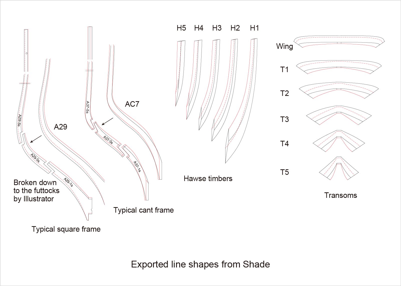
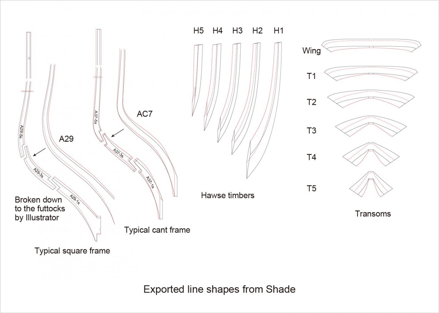
4) These newly generated line shapes can be exported separately as vector data to 2D software such as Illustrator. In case of Illustrator, lines data can be used as it is and no need to modify it at all. 5) This allows you to get hundreds of internal and external frame contour information in just a few hours. Of course, it is also possible to generate Hawse timbers and Transoms by creating curved surfaces of bows and sterns. This is the biggest and most practical feature of this method. Think about how long it takes to draw exactly this many shapes with conventional way, whether it is a PC or by hand. May be it will take years of time. If you read through this topic, you will be recognized that how this method can create them within a short time. 6) On the other hand, in order to make as parts drawings, the accuracy of the shapes is also required, but this software also have a numerical control function of the shape, and the dimensions and coordinates of the shape are reproduced as accurately as CAD. In addition, this method allows you to pass this information directly to the 2D software for making as more practical drawings. The shapes of following figure were generated or drawn with 3D graphics software, i.e. picture drawing tools, not CAD, but can you imagine that? Dimensions are accurately representing the real dimensions of the scaled model. What is distinctive is that the most of curves here were automatically created by 3D software and they are not drawn one by one. As you can see in the frame diagram in it, the original shape can also be freely edited on the 2D software side. To be continued, Kiyoo
-
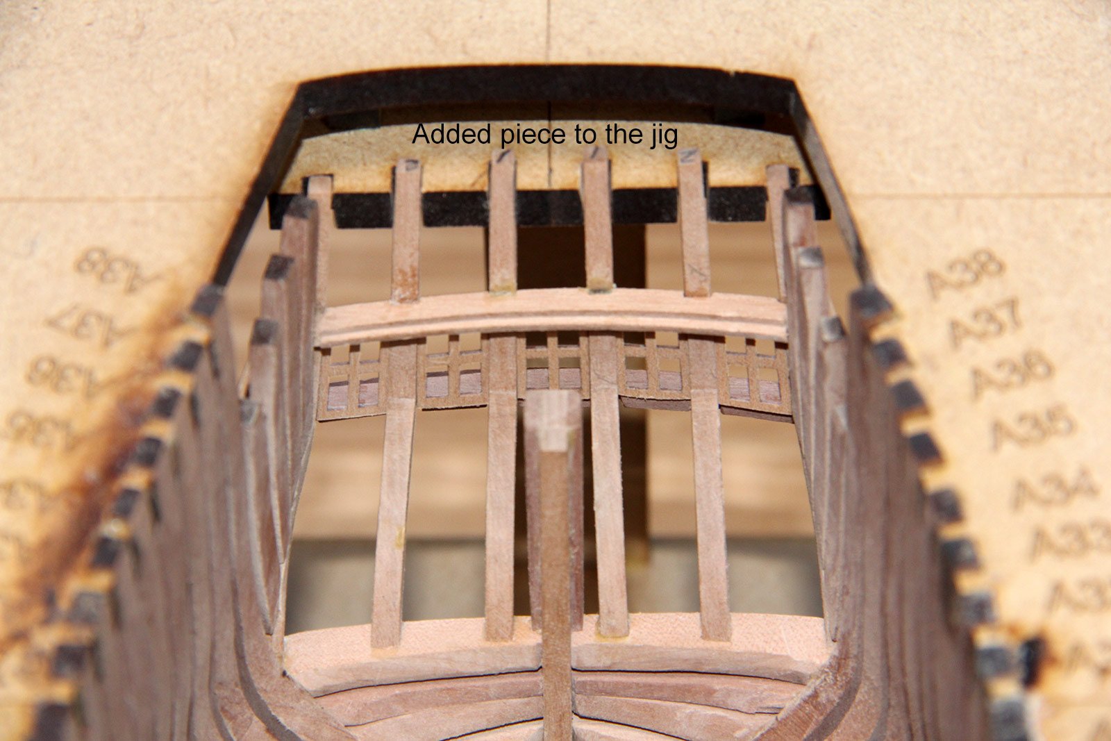
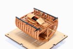
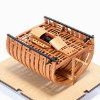
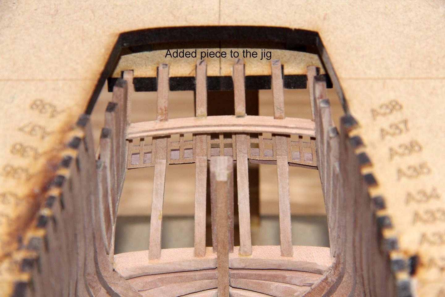
Thanks for the comments everyone. Hi Terry, If Delftship or other similar software can be used like my process, you may have increased your choice. 2D software selection as well. First in my case, laser machine can handle Illustrator data without conversion. In addition, by identifying the line color, it can be added the cut priority for instance hole cut first then cut outer shape etc. Adding the cut beam allowance is done in Illustrator side. It has even offset function and I use this function effectively. These method will also be explained in my introduction. Hi Greg, My last picture may give you a misunderstanding. My building method is basically upright building with vertical extension to the frame. However, the assembly jig is also accurately cut by laser and can be detached and reassembled quite often. My last picture just show that the bottom jig board has been detached for outside fairing. The assembly jig has been also improved few times and added the securing and positioning way for the portion which is difficult to assemble. There are for instance, cant frames, hawse timbers, transoms and counter timbers. Next picture shows the securing the counter by adding a positioning piece to the jig. Oh, I have to hurry up more introduction. Thanks, Kiyoo
-
PietFriet, Thank you for your information on Delftship. After finishing my topic, I will study Delftship. If it is possible to use, it is a big benefit in terms of cost. The software I am using will be explained the details later, but it is a software called Shade by Japanese manufacturer. Shade 3D Official Website Thanks, Kiyoo
-
Hi Kris, Appreciate the ratings. Time is a net time, and it's normal to go back and forth between the material and the screen for actual work. But the point is that instead of drawing hundreds of unspecified shapes yourself, the software generates them instantly once you succeeded to create the smooth hull surface. And it can be used in 2D software side without redrawing the line. I will introduce the software later soon, but unfortunately, it's all subscription software, and it's not cost-effective to have it all on your bed especially from the beginning. However, it is true that owning software has more benefits than cost to increase design freedom. I expect you to share the resulting drawings with some of your colleagues and distribute the costs. Thanks, Kiyoo