
.JPG.ca33079f5815b861e67b9c2cccd37982.JPG)

Blue Ensign
-
Posts
4,333 -
Joined
-
Last visited
Content Type
Profiles
Forums
Gallery
Events
Posts posted by Blue Ensign
-
-
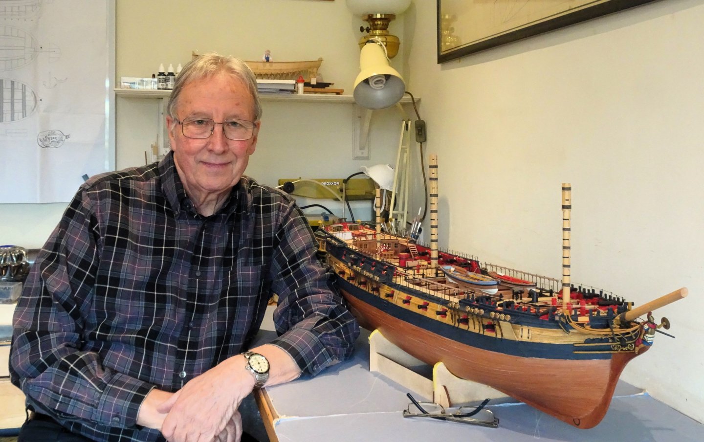
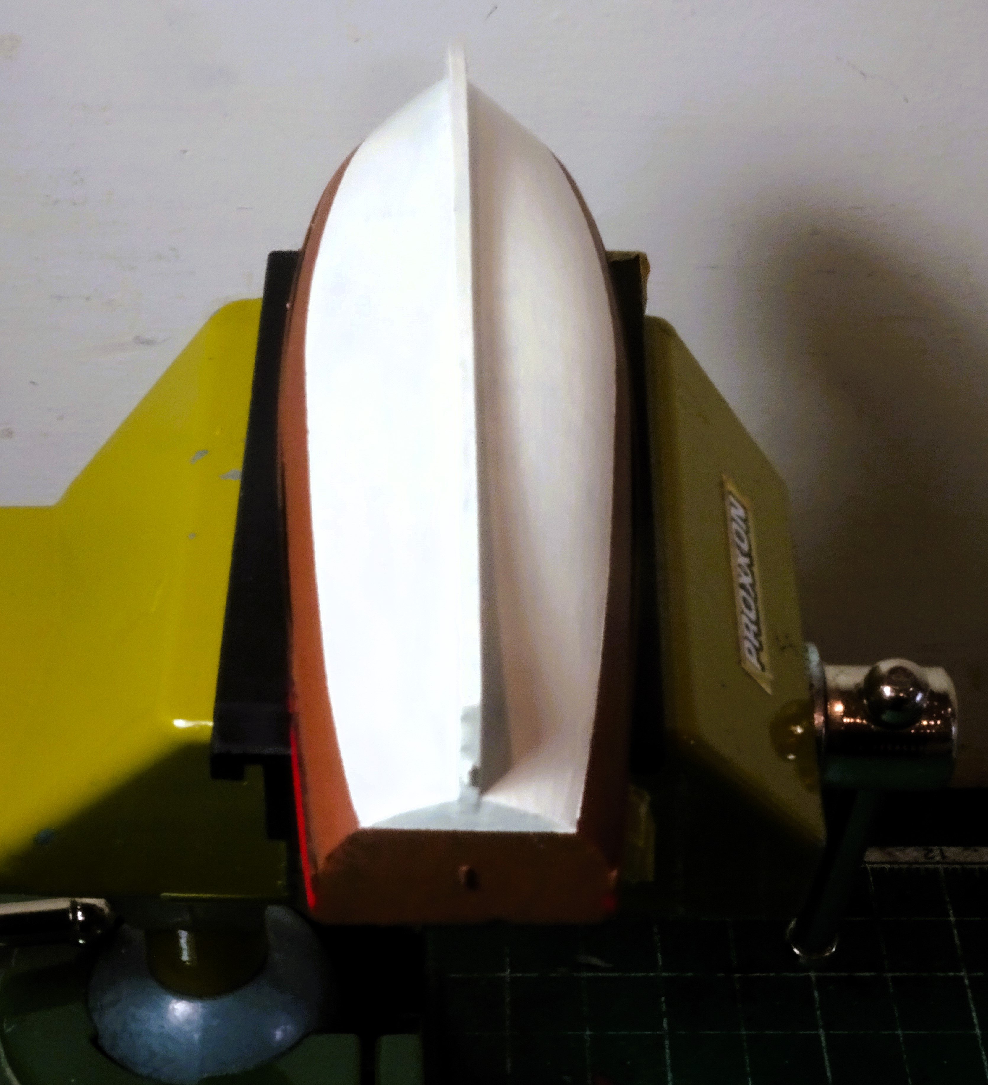
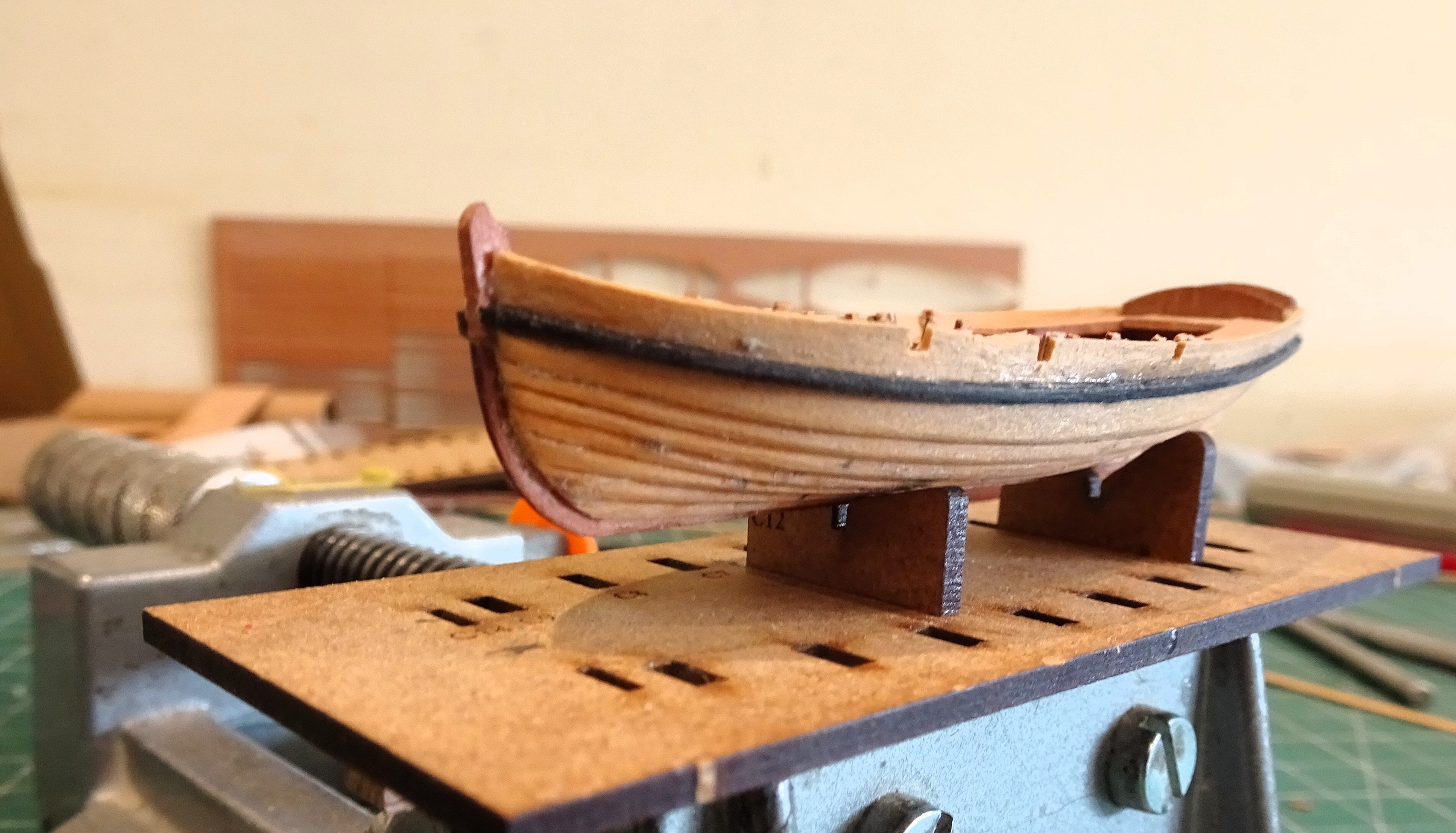
Progress on the hull.
Post 2
The only area that needs cleaning up is the transom.
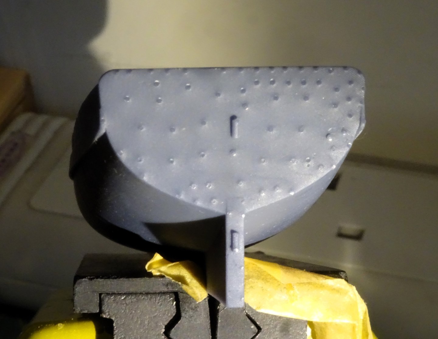
4751
This has a pimpling effect from the moulding that needs sanding smooth, a simple and quick exercise.
Note there are two little protrusions on the transom and stern post that relate to the rudder and shouldn’t be mistaken for flash.

4762
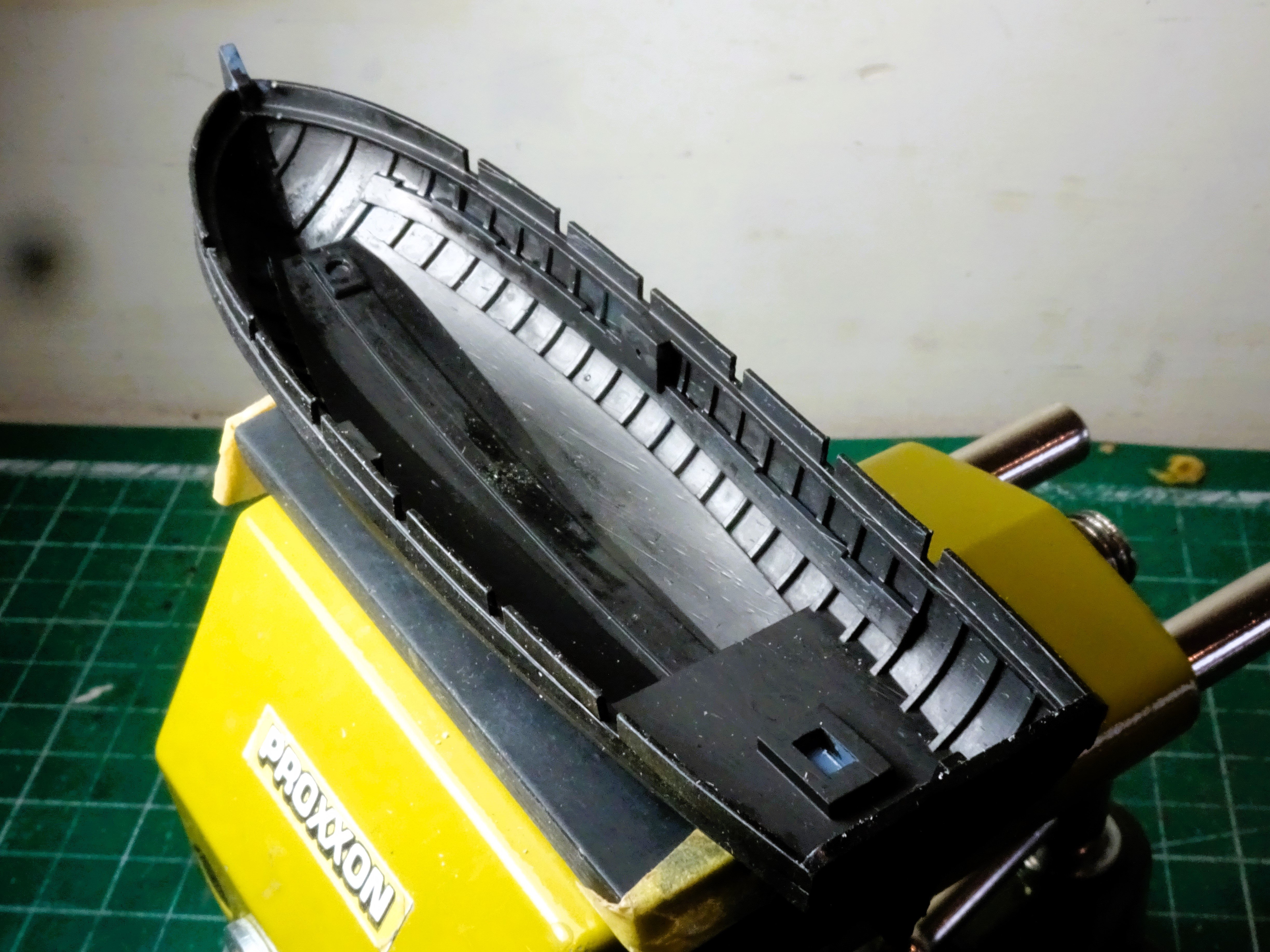
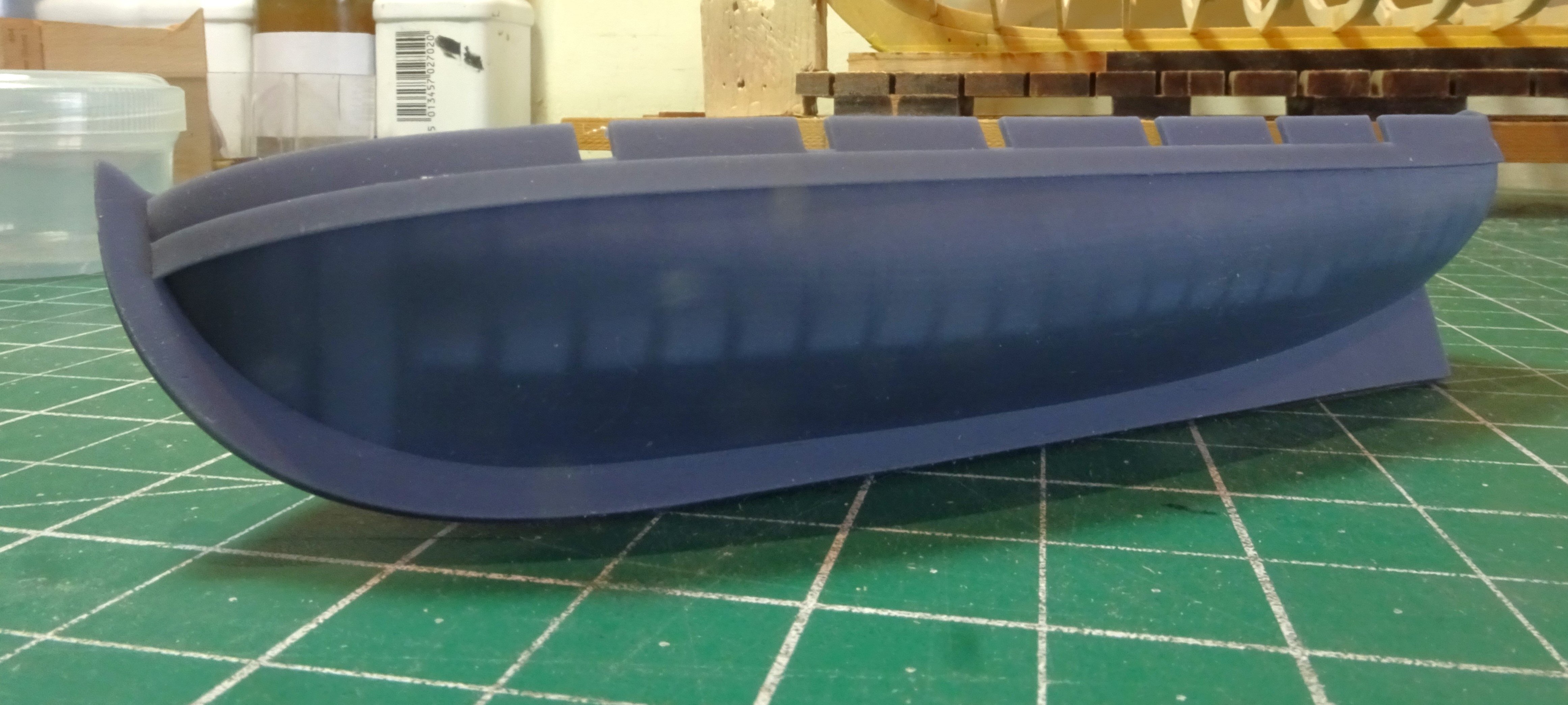
With the resin washed and the parts carefully trimmed as necessary, they are now primed.
I use Vallejo surface primer.
In considering the colour scheme, my aim is to create a look that tones in with the wooden kit boats on ‘Indy’ purely for comparison purposes.
The internal areas of boats were usually painted and with a resin model it is necessary.
I have read that left over paint mixtures known as sad were often applied to the internal planking of ships boats.
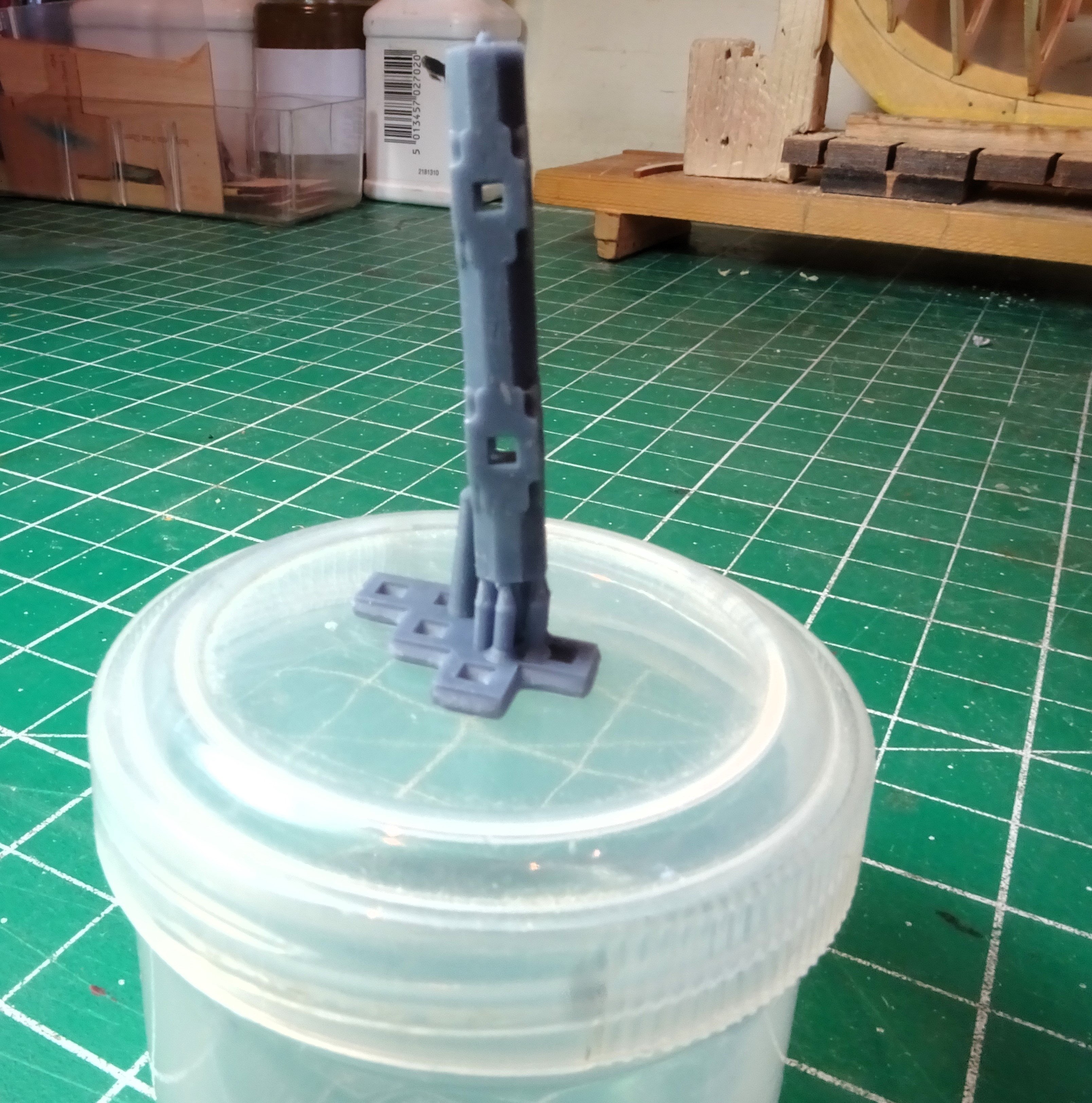
Once the internal painting has been done the windlass can be fitted.
4766
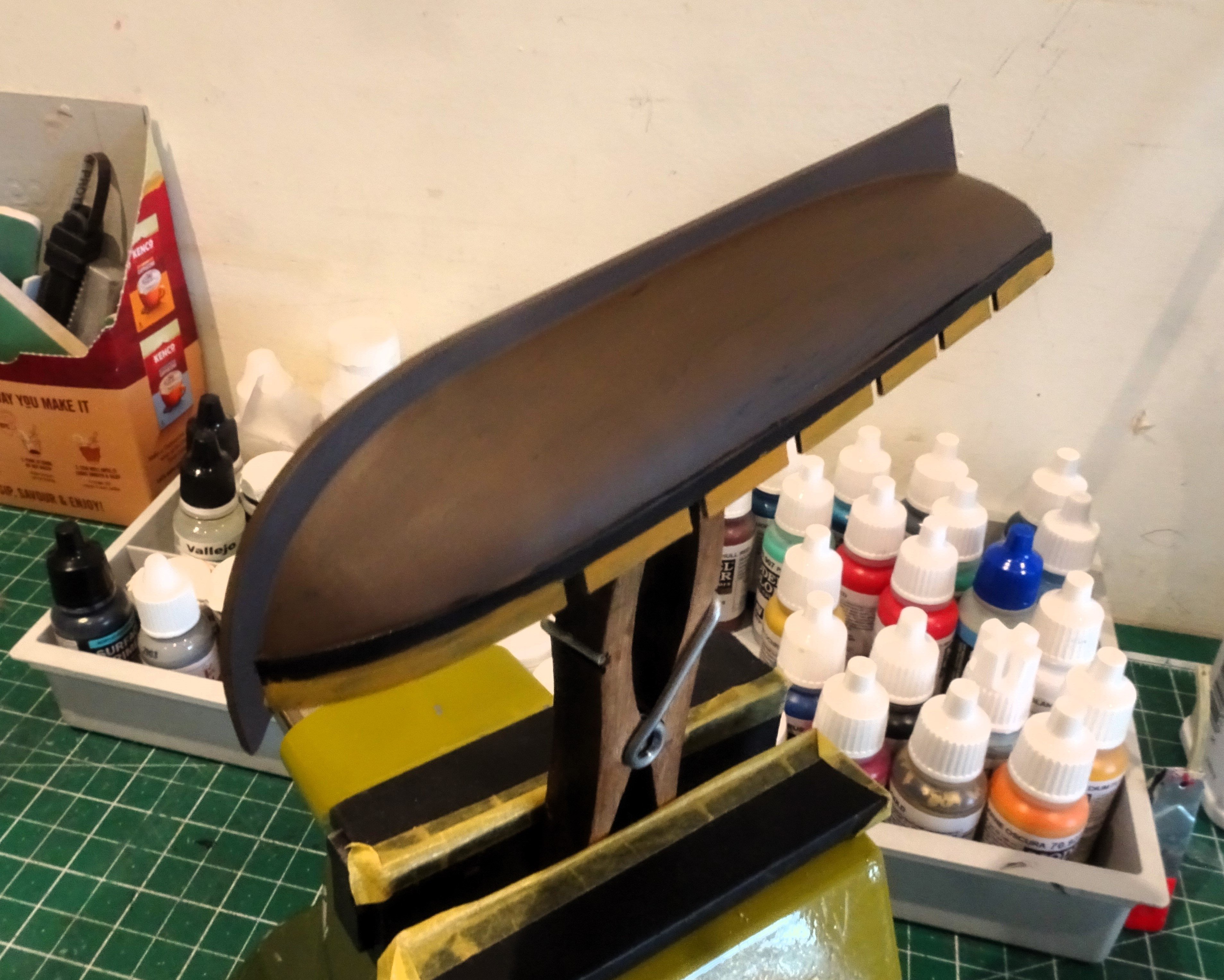
It slots into the housing perfectly, with very little effort. It then provides a useful point to hold the boat for painting the external hull.
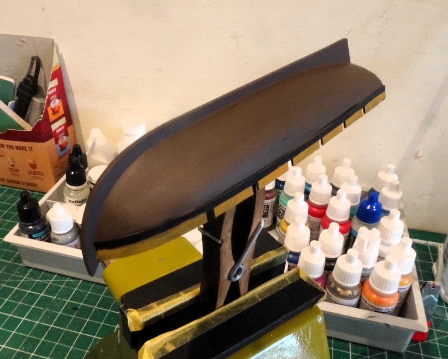
4763
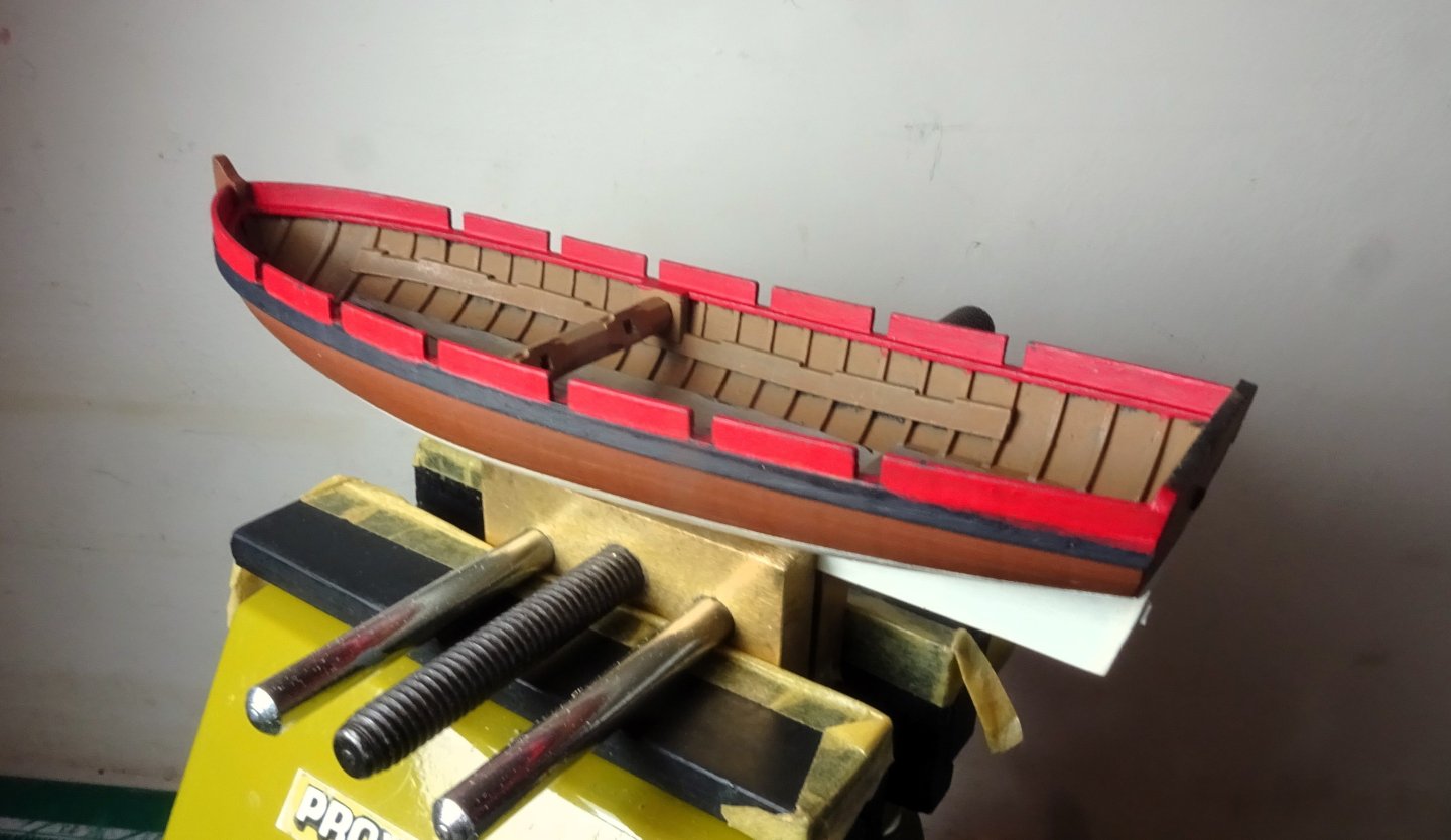
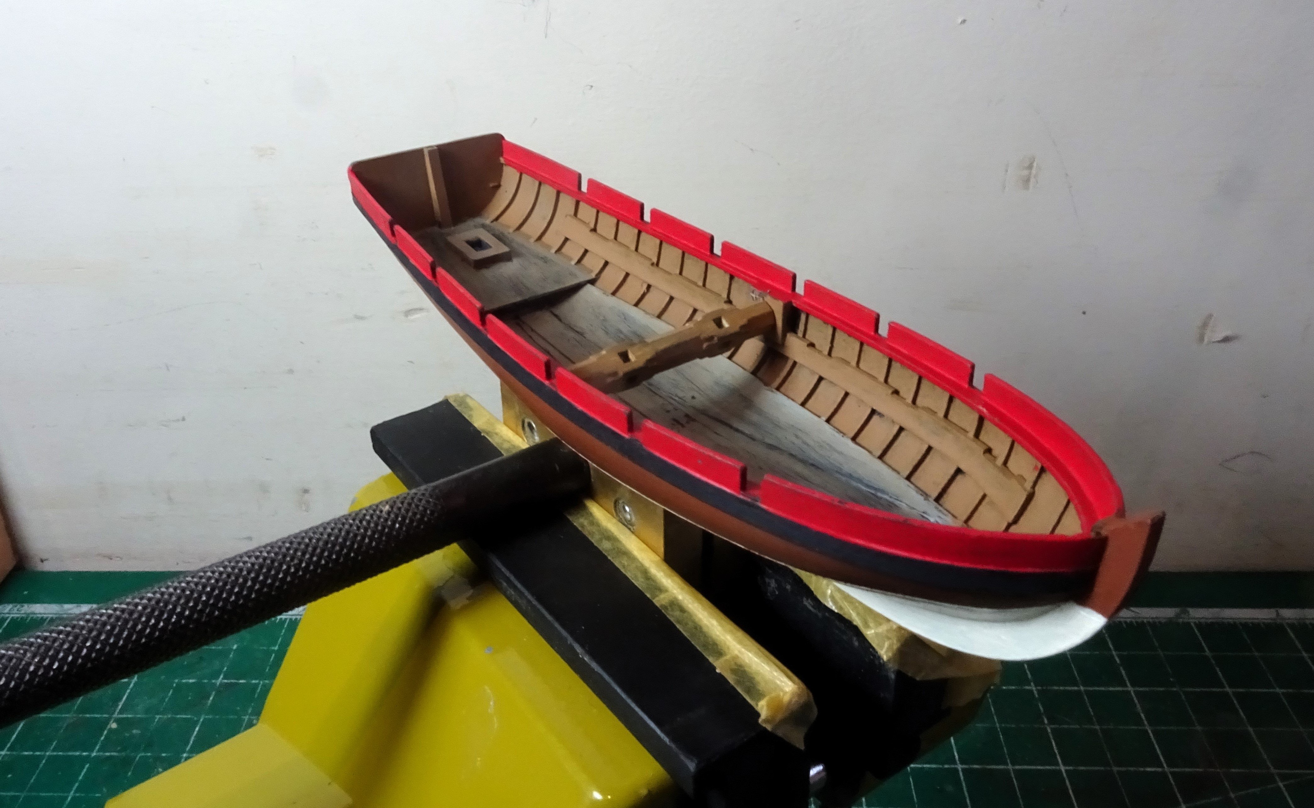
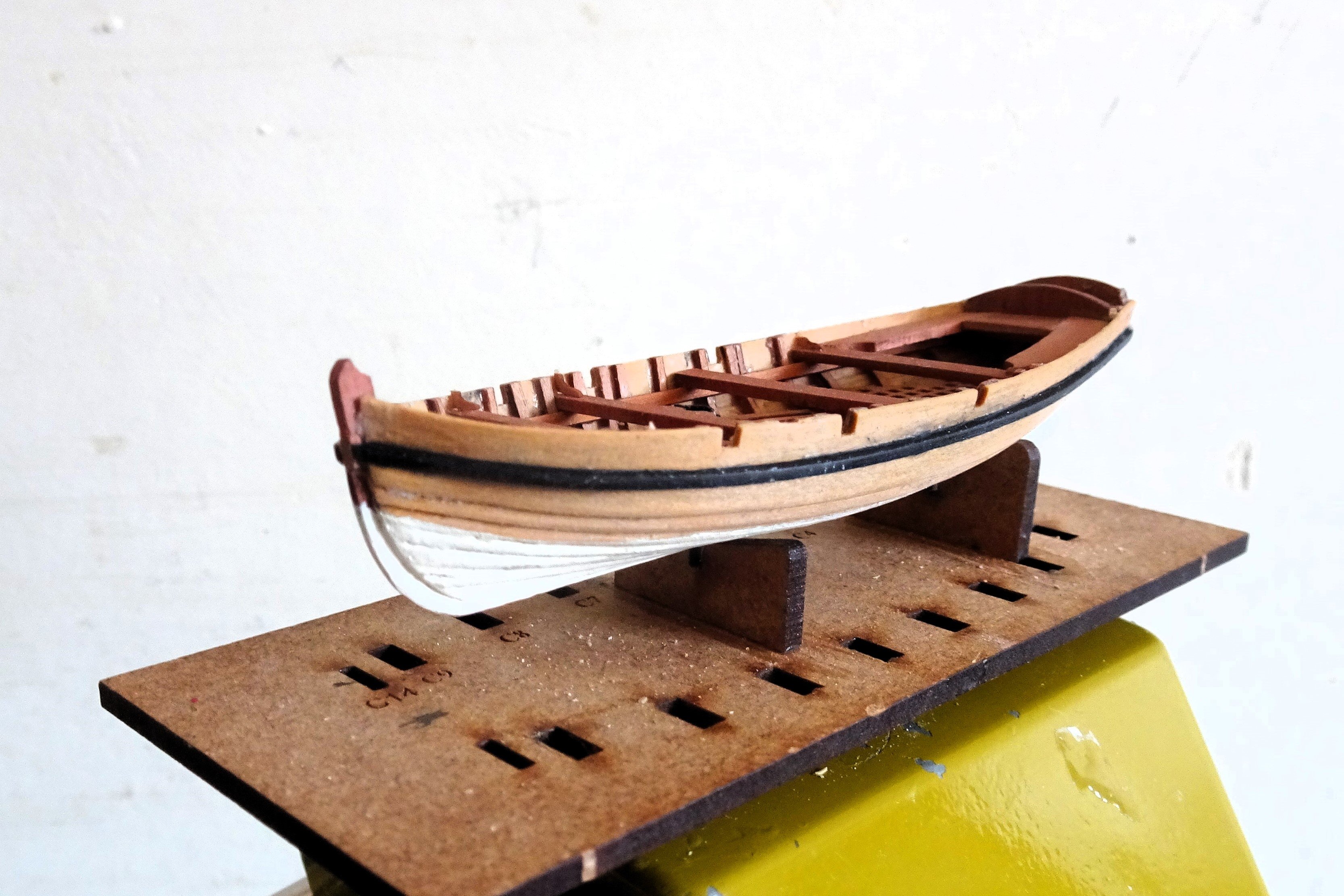
The outer hull painted with a mix of ¾ Burnt umber / ¼ Natural wood.
This was followed by a wash consisting of Flat earth lightened with Ochre brown and tinted with a spot of vermillion.
This was applied over the base and dry brushed.
With acrylics it is easy to play around with colour mixes until a tone that suits the eye is achieved.

4769
4772
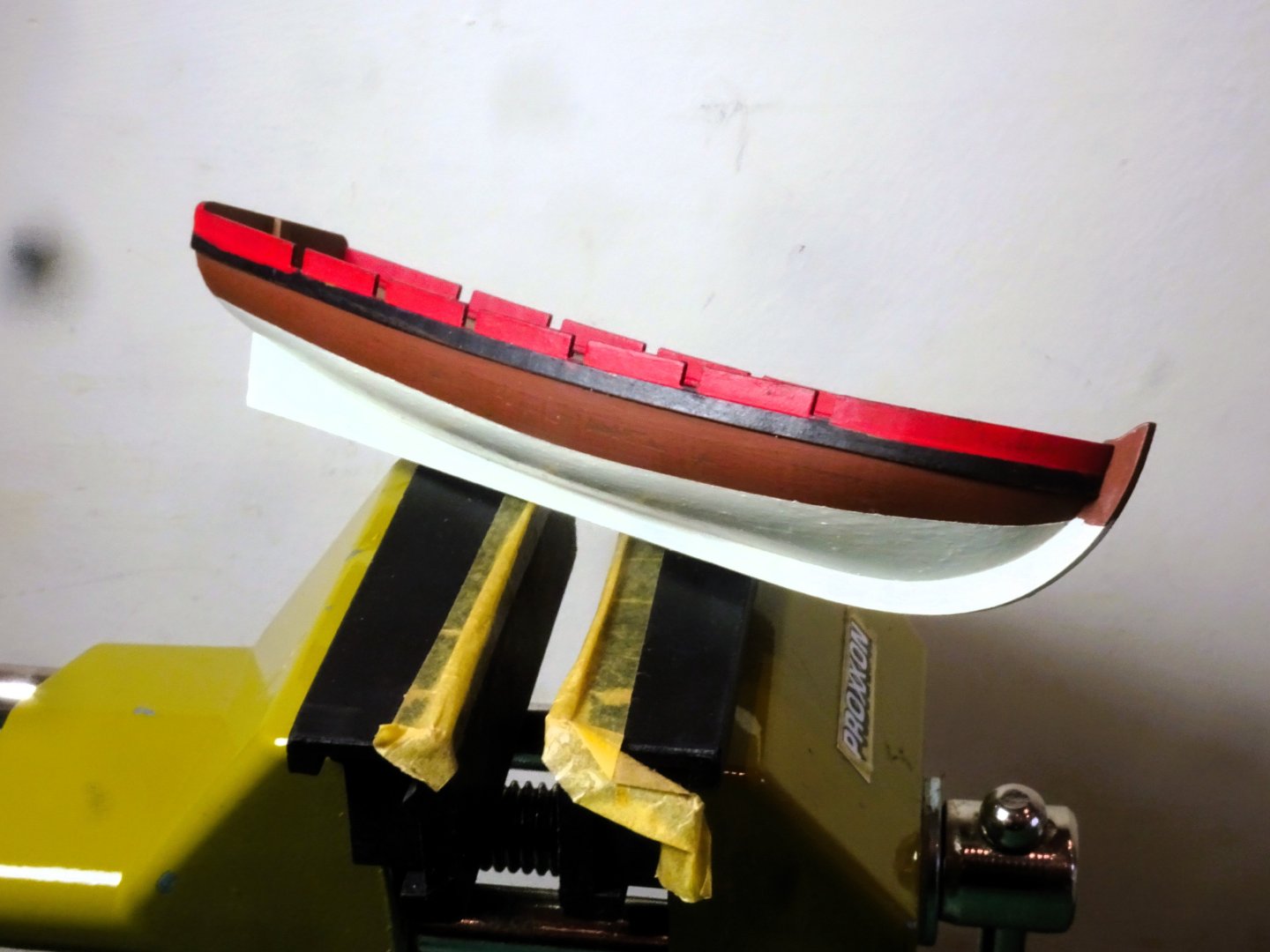
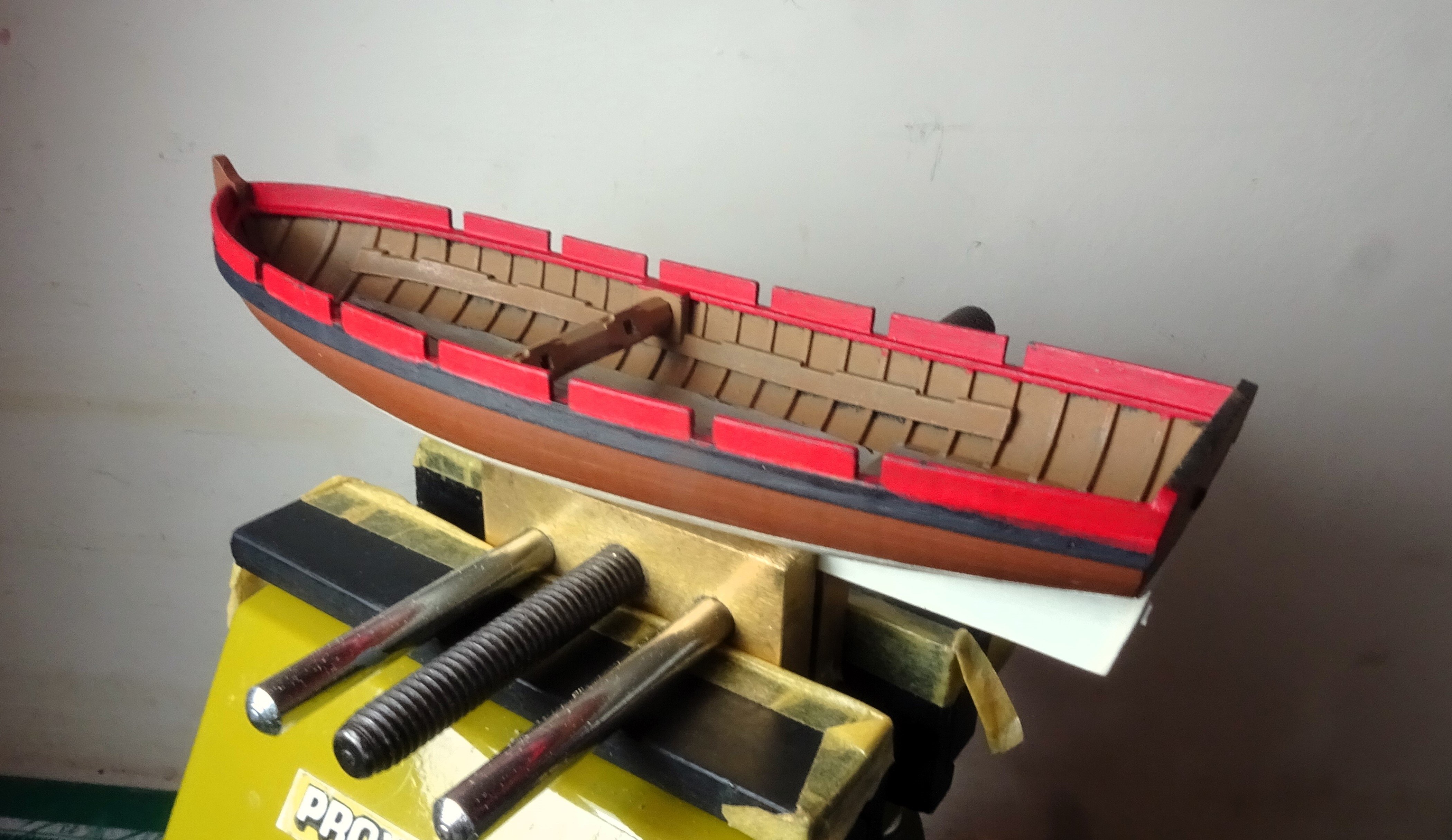
The lower hull was painted using Vallejo Ivory.

4779
4784
Onto the internal fittings.
B.E.
23/05/2024
-
-
Ah, I see, screen shots are beyond my old Windows 11 desk top tech, should have used the iPad.
- thibaultron and mtaylor
-
 2
2
-
Thanks Chris, I did see that but I couldn't get it to enlarge.
B.E.
- mtaylor and thibaultron
-
2
-
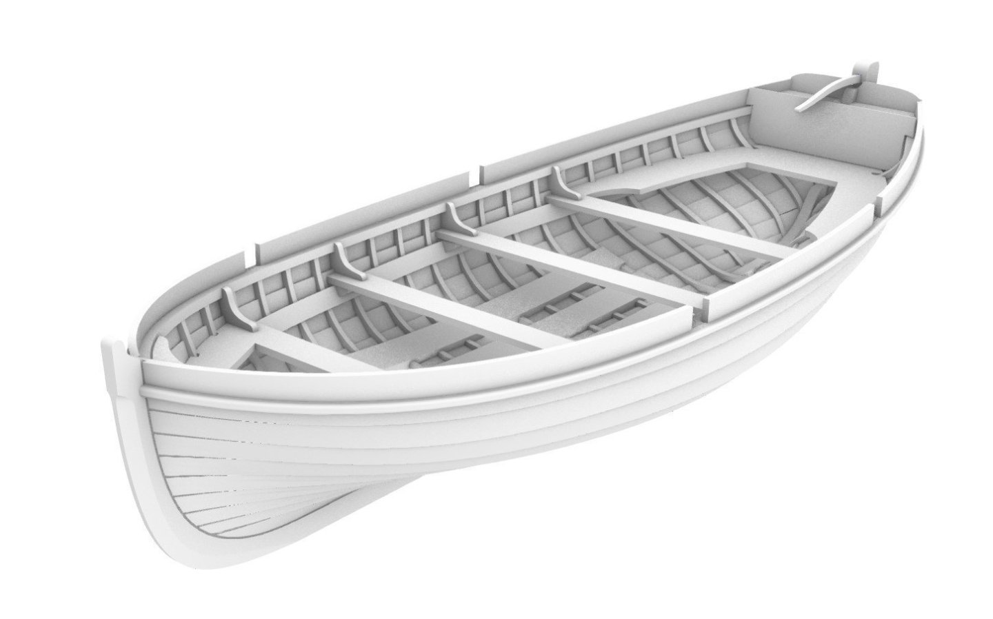
Building the new Vanguard Resin 26’ Launch.
Partly out of curiosity I decided to get one of Chris’s new hot off the press resin launches. It will provide an interesting exercise in woodifying the resin hull and allow me to compare with the wooden kit versions.
It may also help to lay the ghost of my failure with the Indy kit version, and if nothing else I will avoid the frustration of breakages.
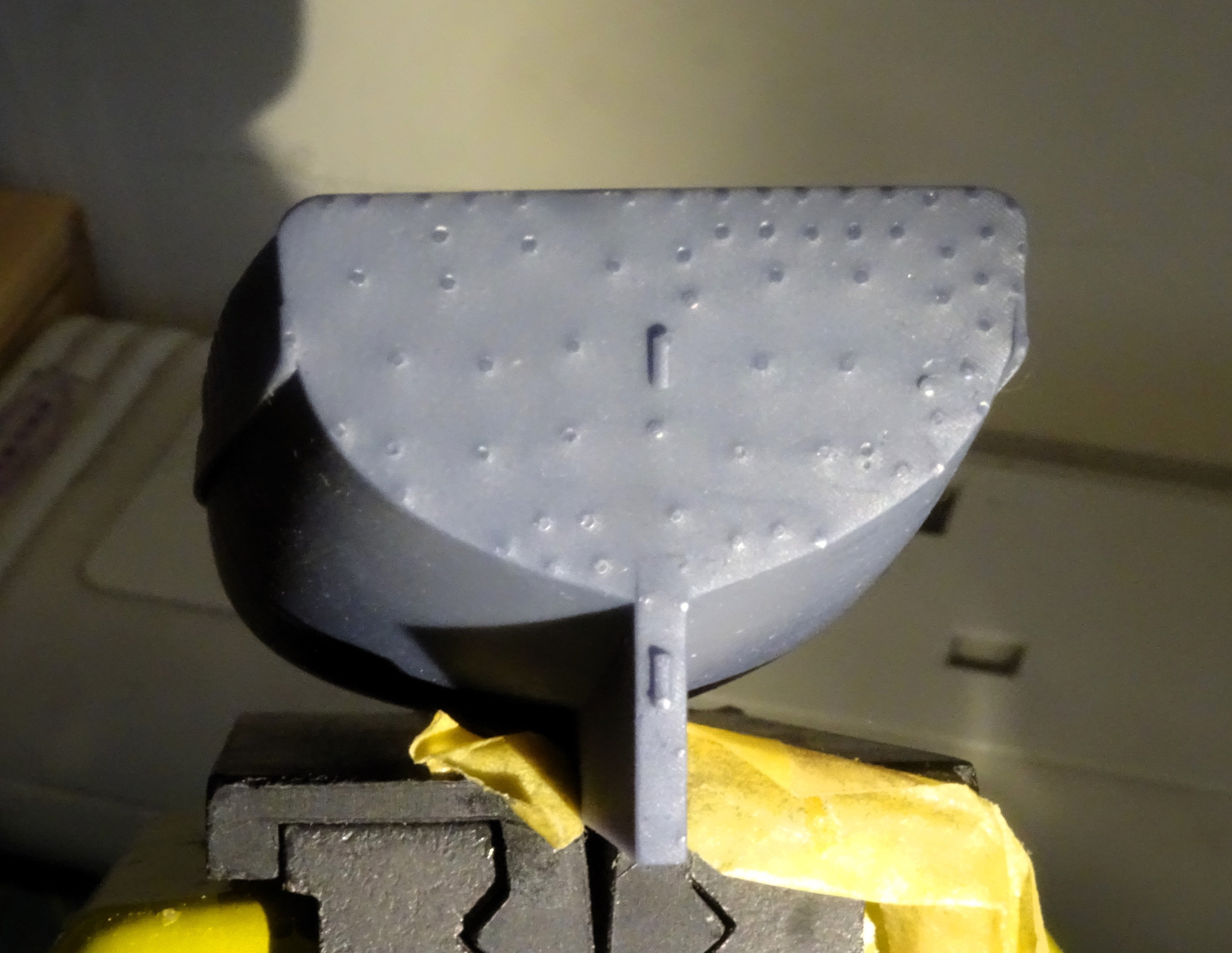
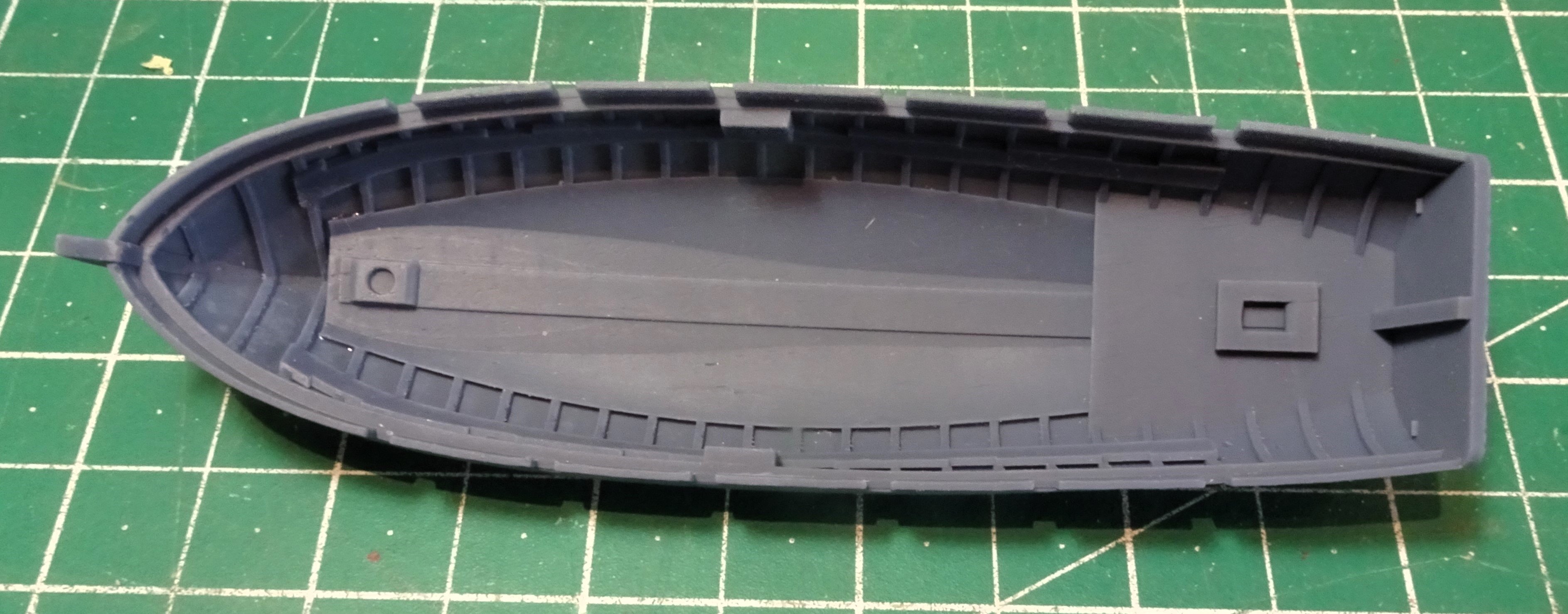
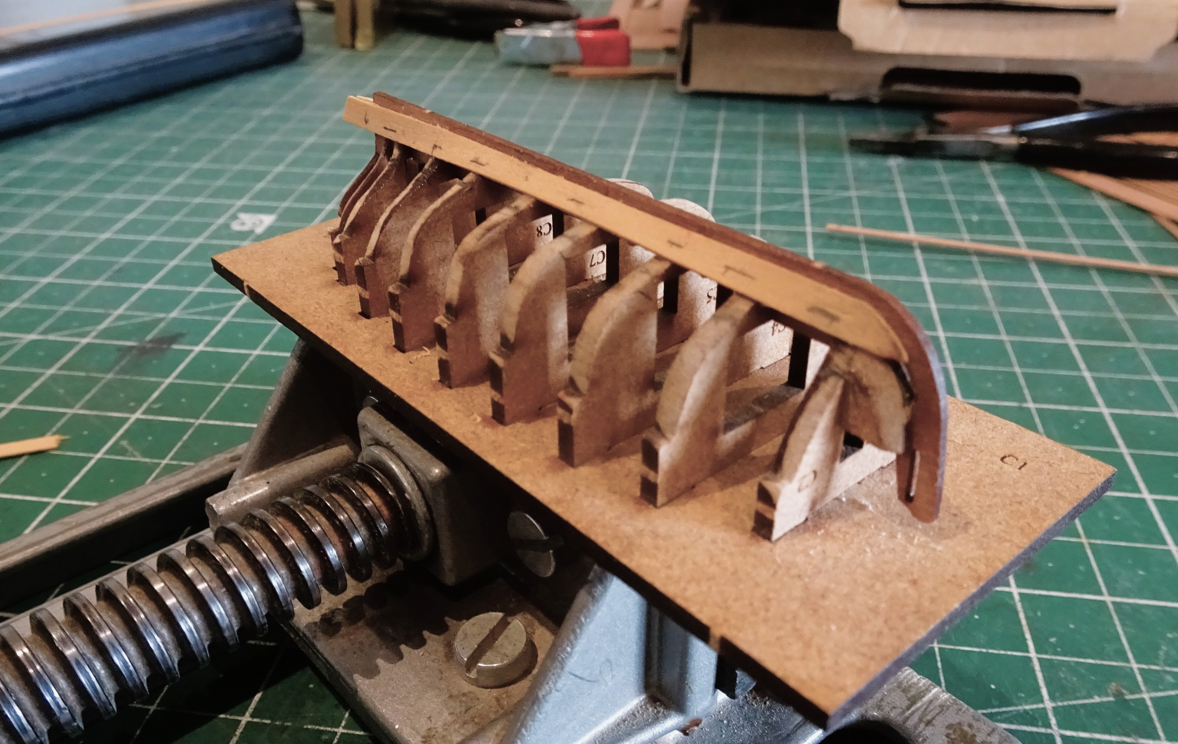
A look in the package
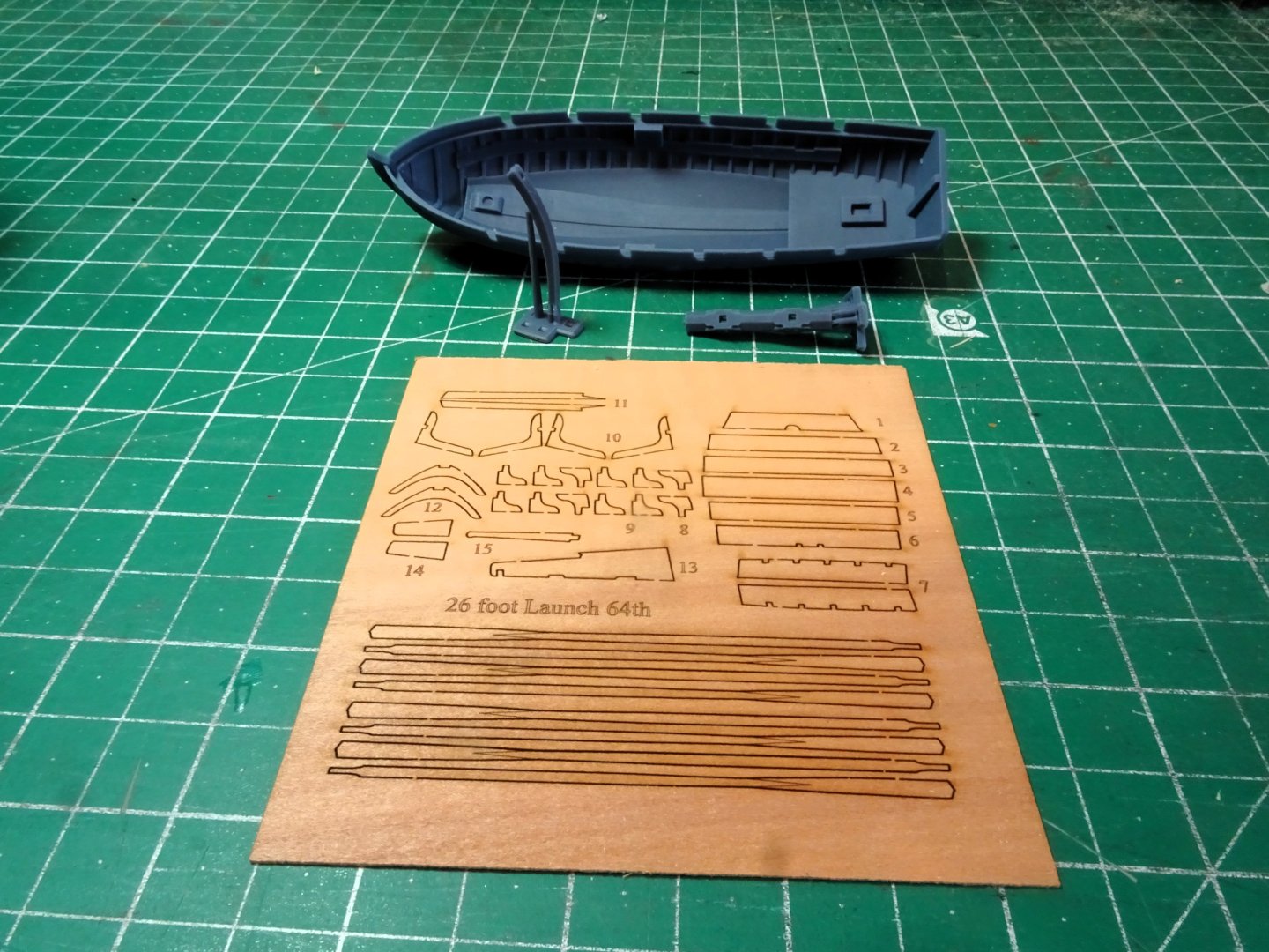
4748
This is what you get.
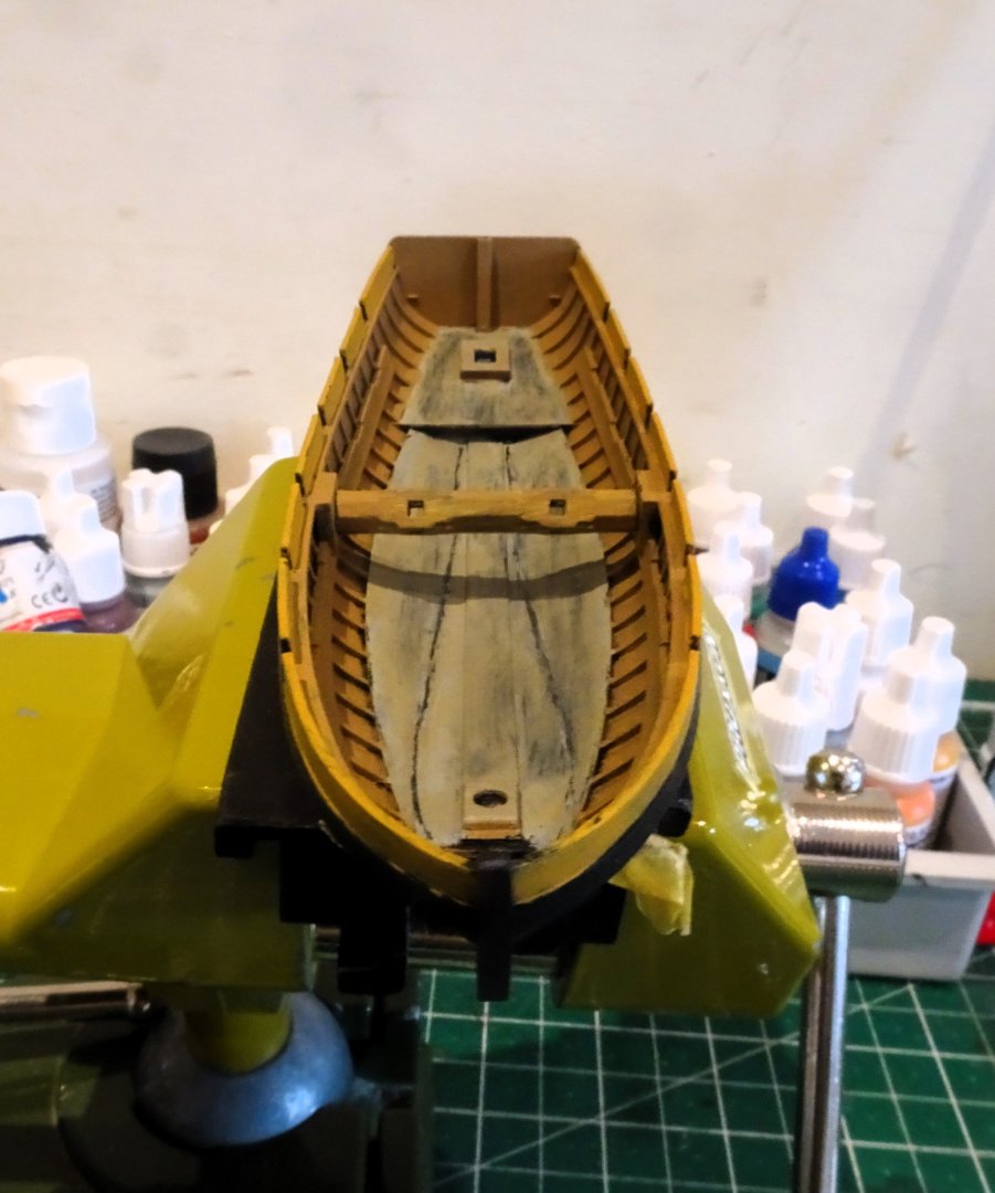
4743
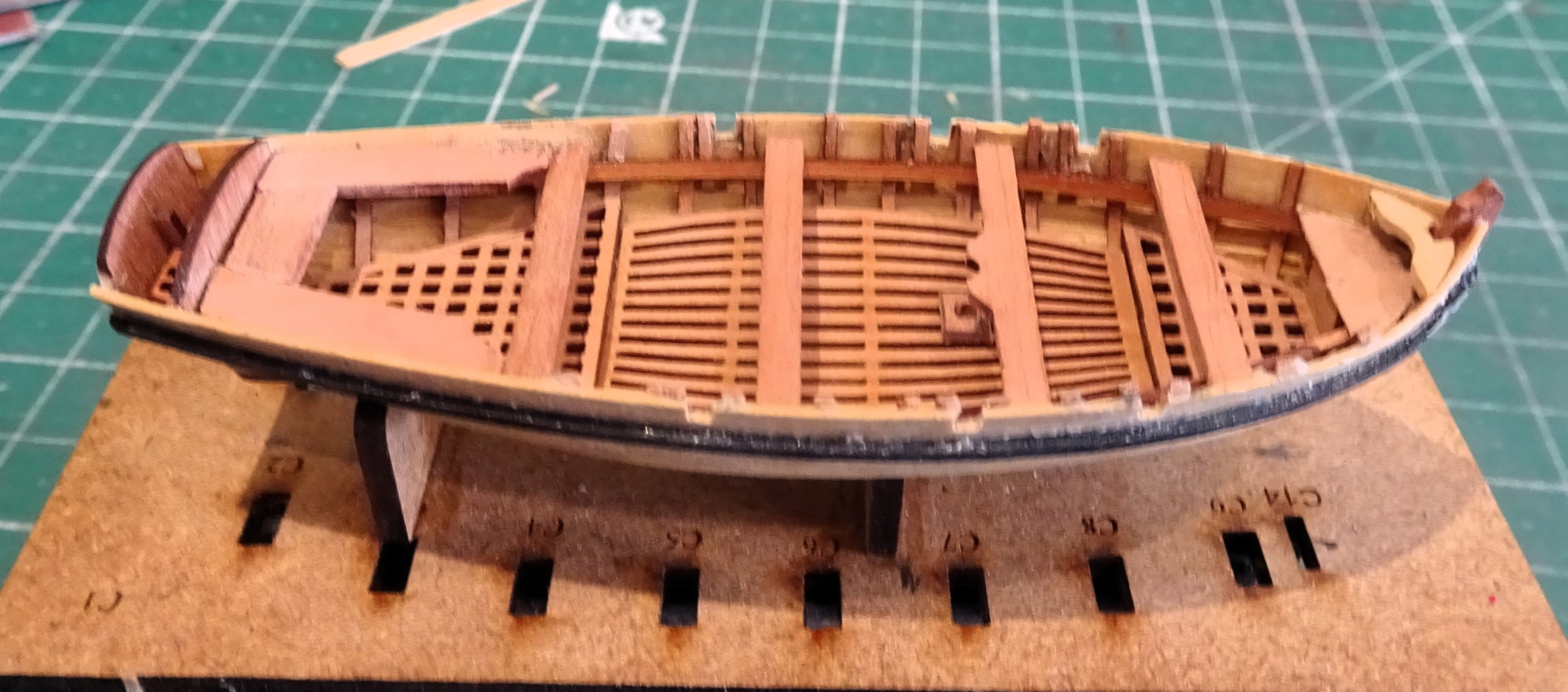
Internally the Keelson is represented together with mast and davit steps.
The solid floor footwaling is represented by broader planking sections for which there is historical evidence.
My current Medway Longboat also has much broader floor planking.

4741
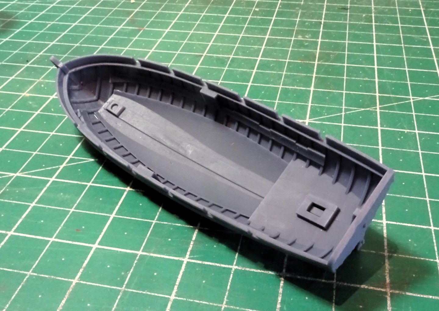
The moulding is very nicely done and looks to need very little clean -up beyond washing the resin.

4742
I note that there is no indication of external planking strakes, possibly thought unnecessary because the hull must be painted and they would be pretty fine and not show thro’ the paint.
The oar arrangement is for double banking, which is appropriate given the Admiralty order of 1783 regarding Launches.

4745
The significant feature of a Launch, the windlass, is also supplied in resin. I am pleased that this feature has been included, these are tricky to make at 1:64 scale, I know, I made one to go with the Launch for Sphinx.

4746
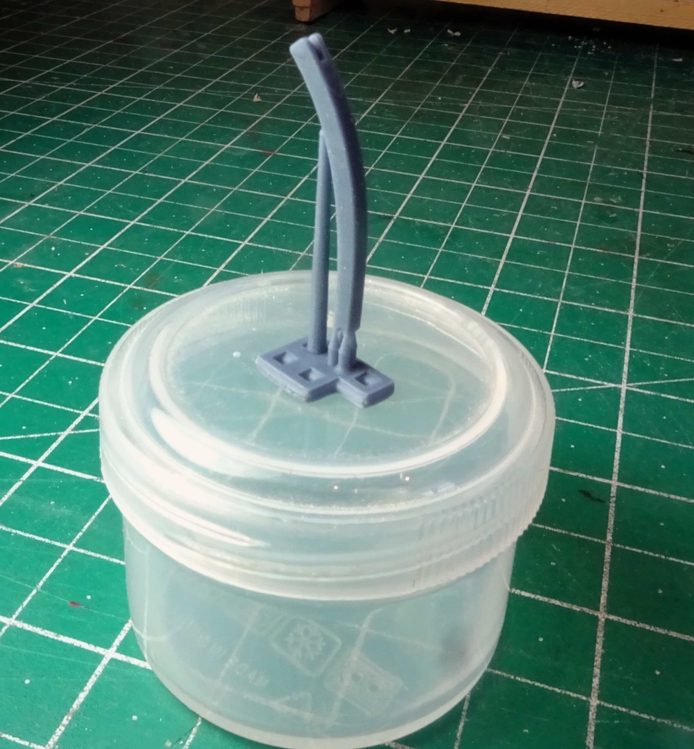
The remaining Resin fitting is the davit.
I don’t think there are any instructions with these kits but then there is not much in the way of construction required to complete the model. All the hard work has been done, internal framing and the all-important thwart supports are moulded in.
The thwarts and stern sheets are of 0.8mm Pearwood and look to simply slot into place with minimal effort.
The key factor in producing a fine model is all in the painting with this medium, we’ll see how I get on.🤔
Both the Resin and the alternative wooden kit versions are the same price at £29.00. The difference is that with the wooden version brass etch grapnels and boathooks are included, along with a good serving of tricky building time, but it doesn’t have the windlass.
I wonder if the Resin fitting would be appropriate to supply with the Pearwood Launch version as an optional extra?
On with the assembly.
B.E.
21/05/2024
- thibaultron, Doreltomin, dunnock and 9 others
-
12
-
Post 19
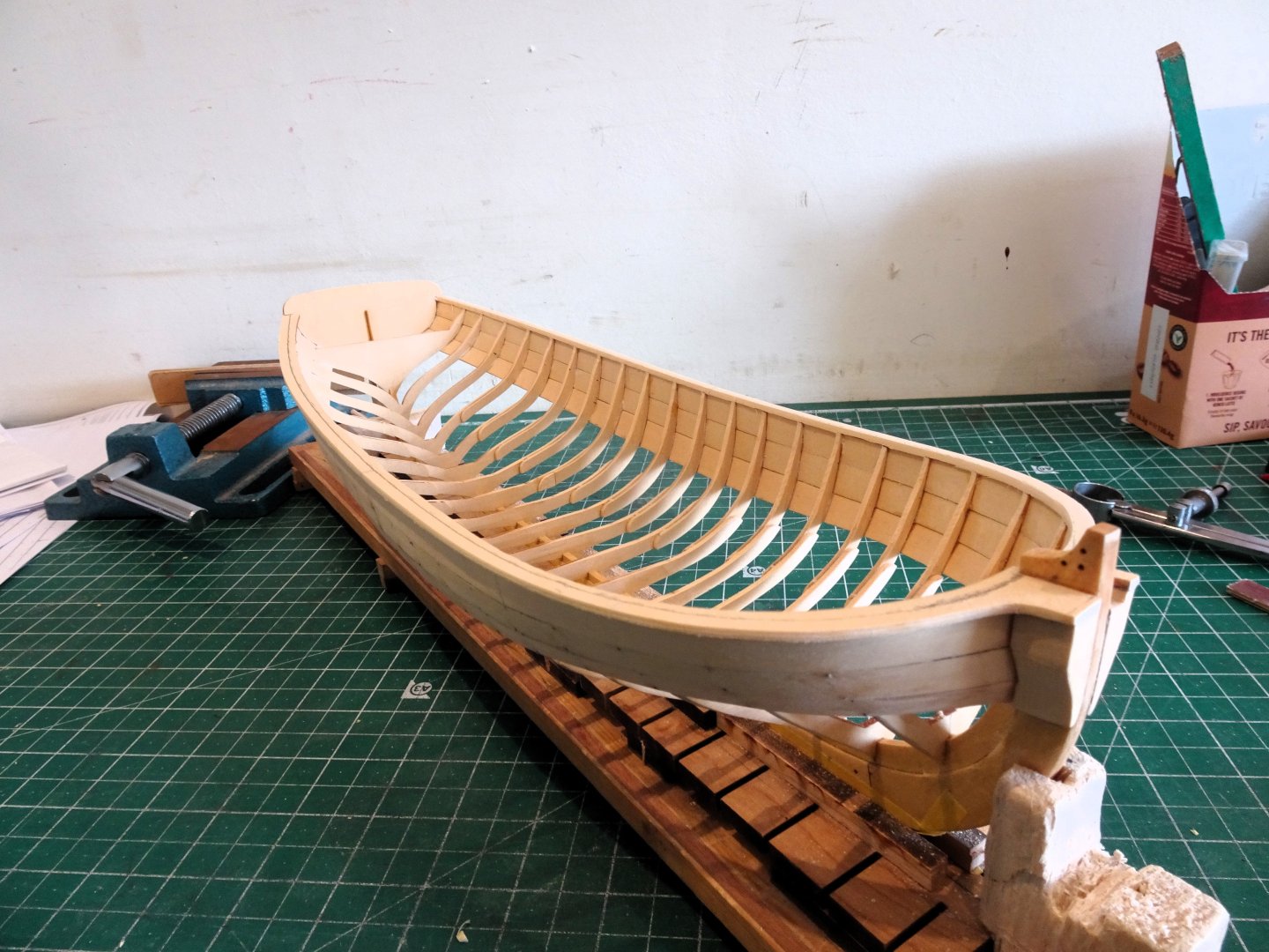
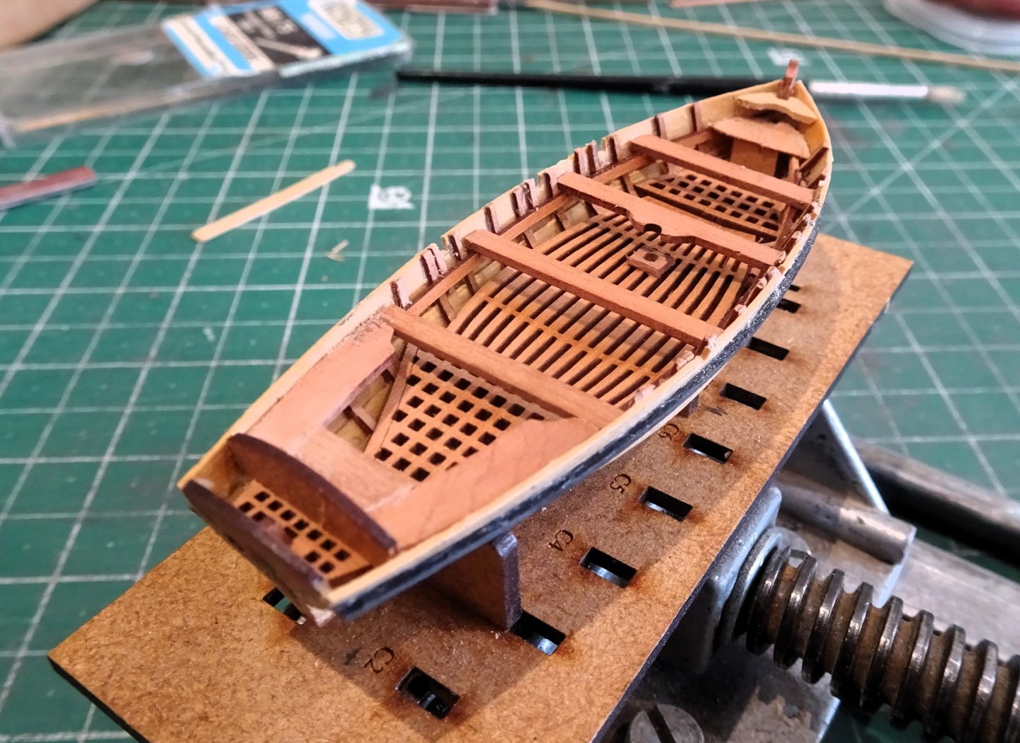
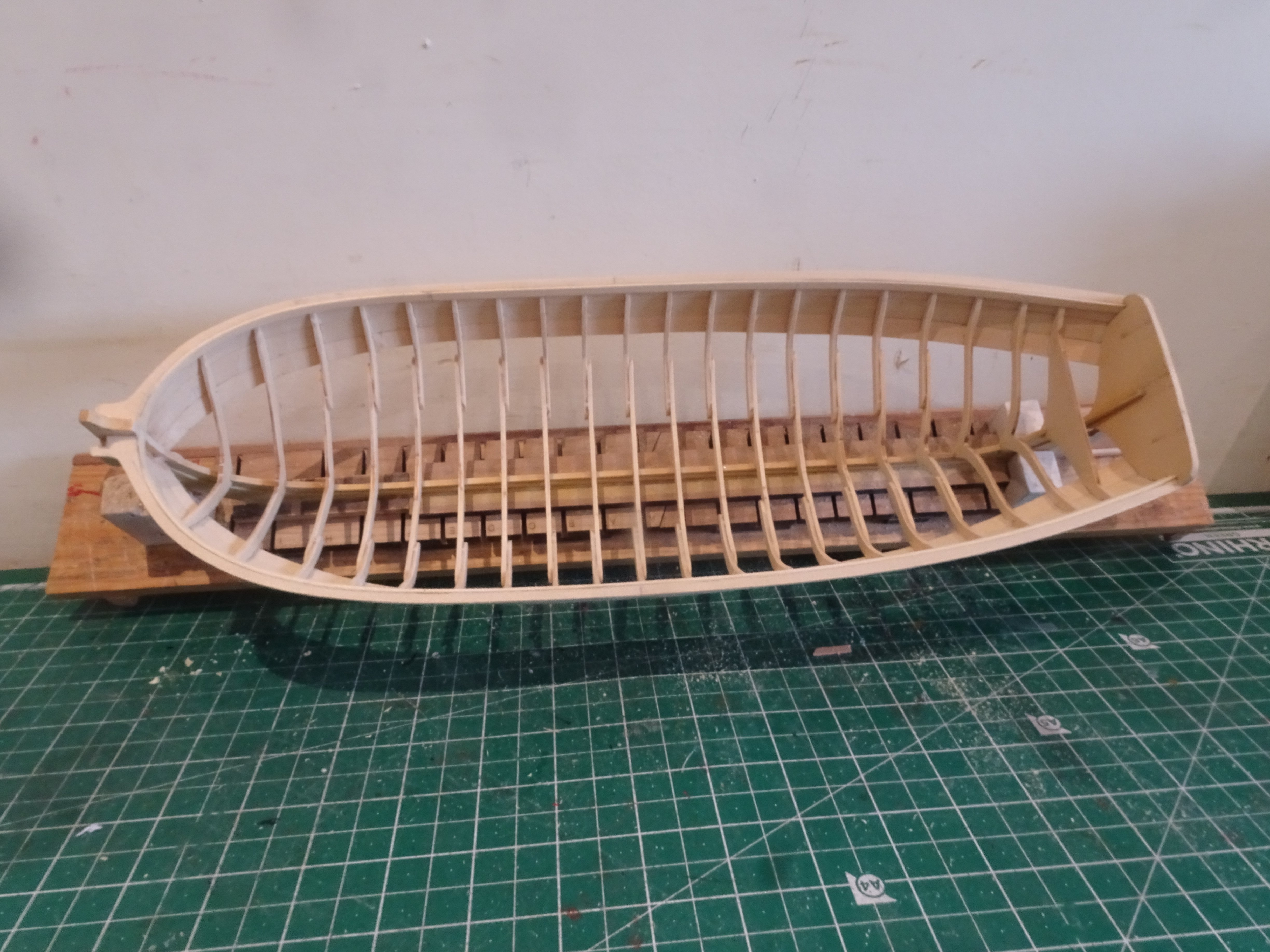
Cap rails and frames cont’d
Over the past week I have continued to work on the frames and Capping rails, slowly easing myself back into the build.
The starboard side is pared down using the same procedure as before.
4692
For sanding I used 320 grit paper.
With the Cap rails down to around 5/32” width the inboard sheer strakes can be fitted.
These comprise two laser cut planks (1/32” x 5/32”) for each side, a bow section and longer aft section. The sections are pre spiled to take account of the bow round and sheer.
Having lost familiarity with the kit contents it took me a while to locate these which are on sheet ‘R’ of the planking sheets.
4725
The bow sections were wetted down and pre-formed around the bow before fitting.
4727
4729

4730
The inboard strakes have now been fitted, one or two spots of char to attend to but this section is nearing completion.
There is a bow knee to be fitted and the kit supplies laser cut pieces from cedar.
The kit part was not a good fit on my build requiring too much material removal and/or filler to retain the elegant shape.
4734
I remade the part from Boxwood sheet having taken a template, but even so this will still require some fettlin’ to get the hoped-for razor line fit to the capping rail at the bow.
B.E.
21/05/2024
- JpR62, hollowneck, Thukydides and 3 others
-
6
-
Post One Hundred and Seventy-six
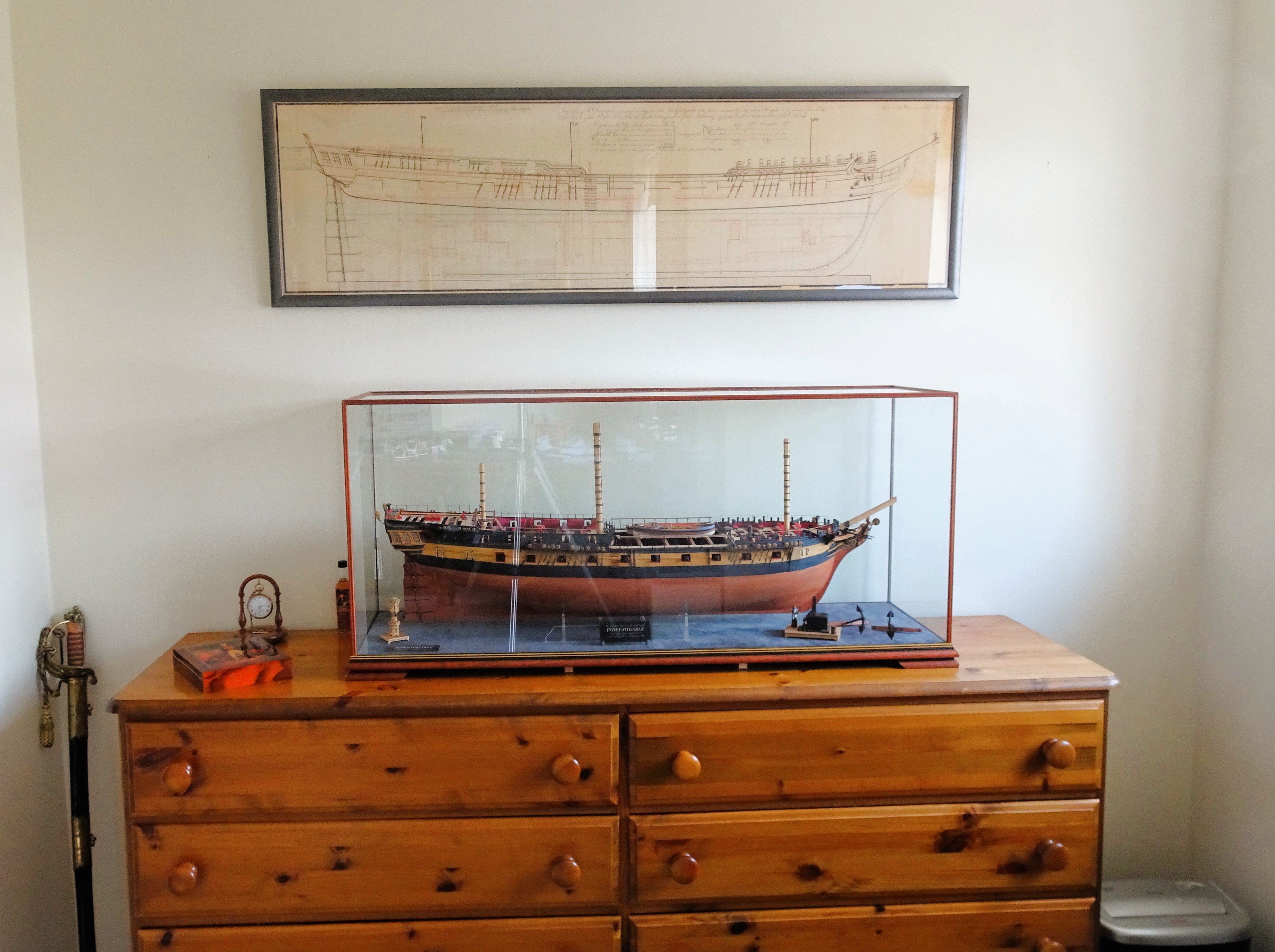
Casing the model.
Today 'Indy' was finally encased and moved to her display position.
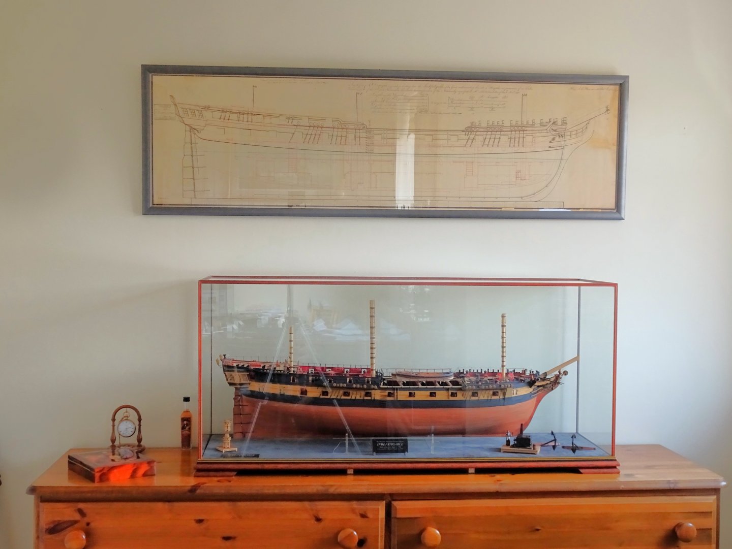
4713
Quite a fraught business lifting the heavy glass cover over the base, but at least there are no tall masts to negotiate and yards to snag.
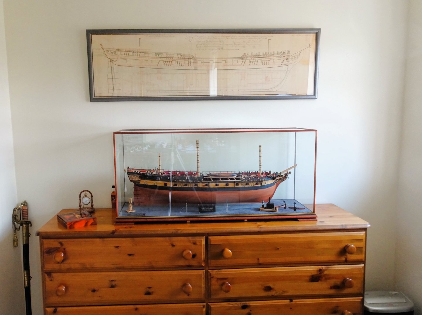
4717
The cover was set with the model/base on the floor, and the combination case lifted in two stages onto the chest of drawers.
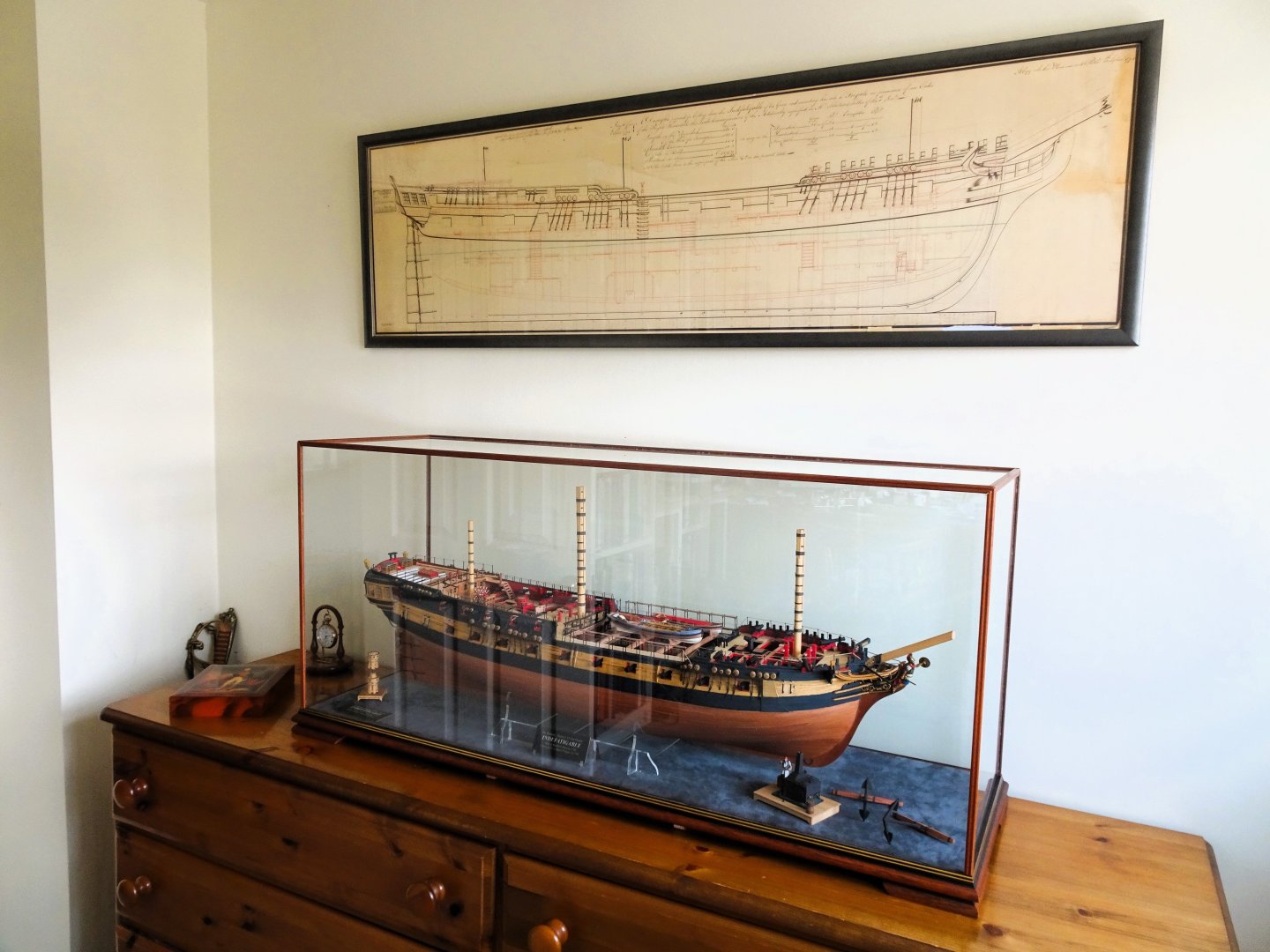
4715
I had been waiting for the arrival of the ‘Indy’ Admiralty plan which I have had framed. This was also a tricky exercise to hang being 53” in width, supported by three hooks.
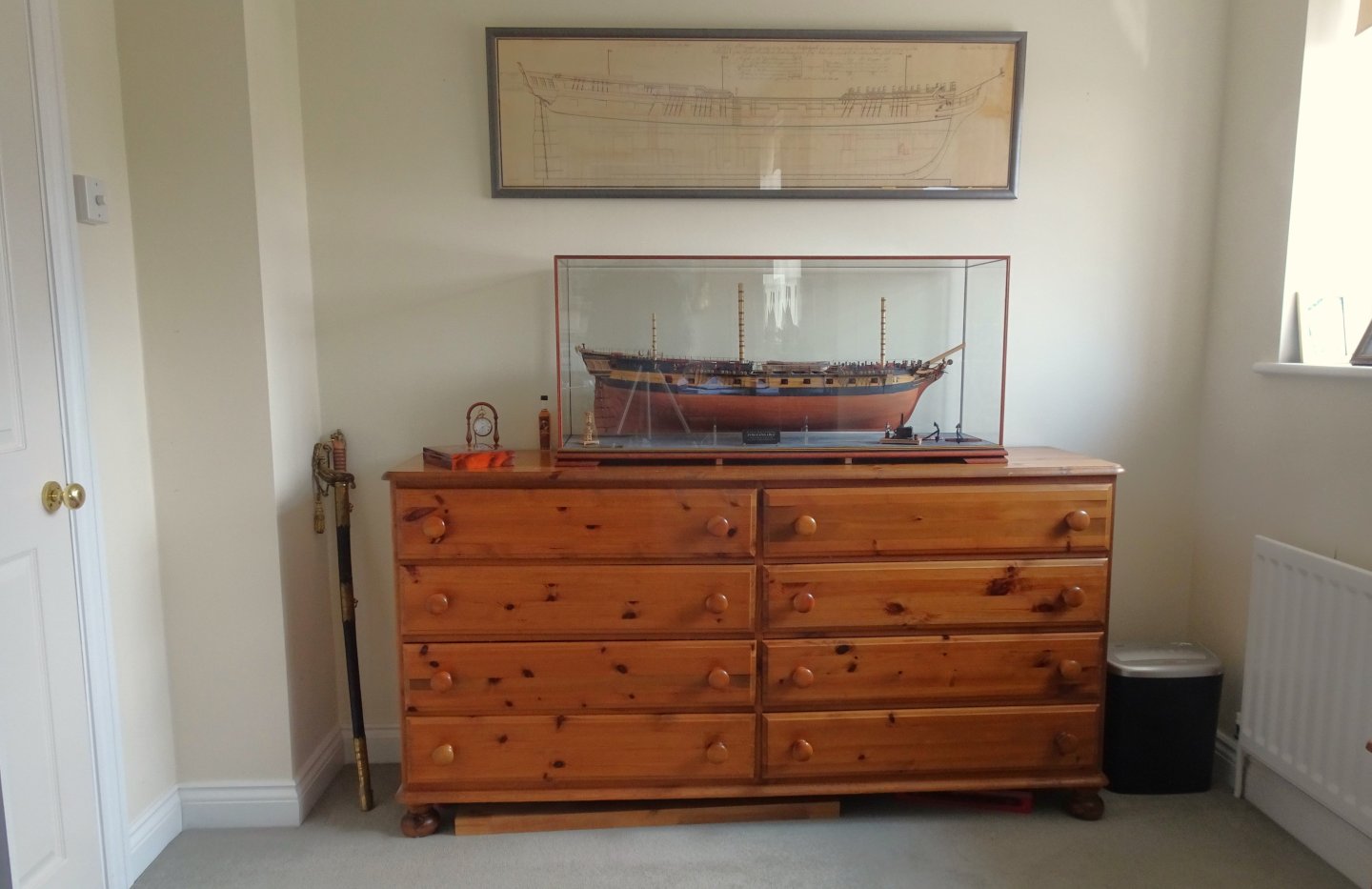
4708
This is the last available space I have for a large model, but I think I can still accommodate a few smaller ones.

4723
The final act is to compile the build photo record book that I do for all my builds, this is now ready to go to the printers.
I can now finally declare the project completed, and I again thank those who have shown an interest.
Regards,
B.E.
18/05/2024
-
-
19 minutes ago, Kevin said:
i am not a NRG member, im not good enough to be a member, however i was not aware i had to research the kits that i review, its a way of informing others that new kits are on the market, that might be of interest, perhaps we need another thread, kits reviewed by non NRG members - rant over, and i wont bother again
You don't have to be 'good enough' to be a member of NRG Kevin, just pay the membership fee, I'm a member - case in point.🫤
B.E.
-
Perhaps I should take another sabbatical and wait to see what little pearls I can pick up from your build Glenn.😉
On balance, perhaps I should just get on with it, my kit sat for four years beneath the bench, plus another two the stocks.
Post 18
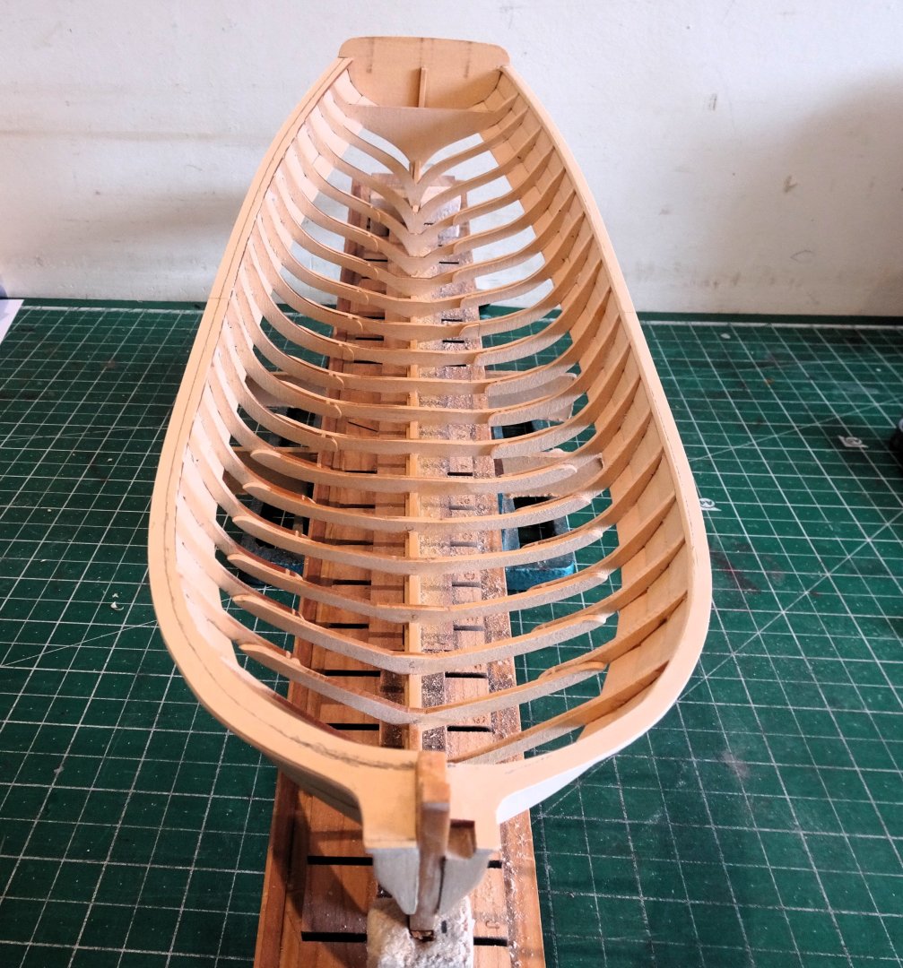
Cap rails and frames
The Cap rail now needs to be thinned down. Chuck indicates an initial 1/32” overhang on the outer side. I use a strip of 0.8mm x 4mm Pearwood strip as a template.
4684
The trickiest part is around the bow in the area of the bolsters, here I used a scalpel blade to carefully pare away the excess overhang down to 0.8mm whilst retaining the uniformity of the rail.
For thinning the frames as they move upwards to the rail I initially use a scalpel, the cedar cuts smoothly and uniformly, and for this aspect the blade is quicker and cleaner than sanding alone.
4685
The support base holds the hull steady for use of the scalpel and sanding. Some of the frames are thinned with the hull side down, others with the hull upright. Fine cuts are used to remove the timber.
As the frames are reduced the cap rail width is reduced until the required width of 5/32" (4mm) is achieved.
4690
The ports side frame fairing and cap rail reduction near completion. I have left the inner bow area slightly oversize until I reach the stage of fitting the knee at the bow.
The starboard side shows the extent of the timber to be removed.
4691
So far, so good, I’m enjoying getting back to working on Chuck’s little gem.
B.E.
15/05/2024
-
Post 17
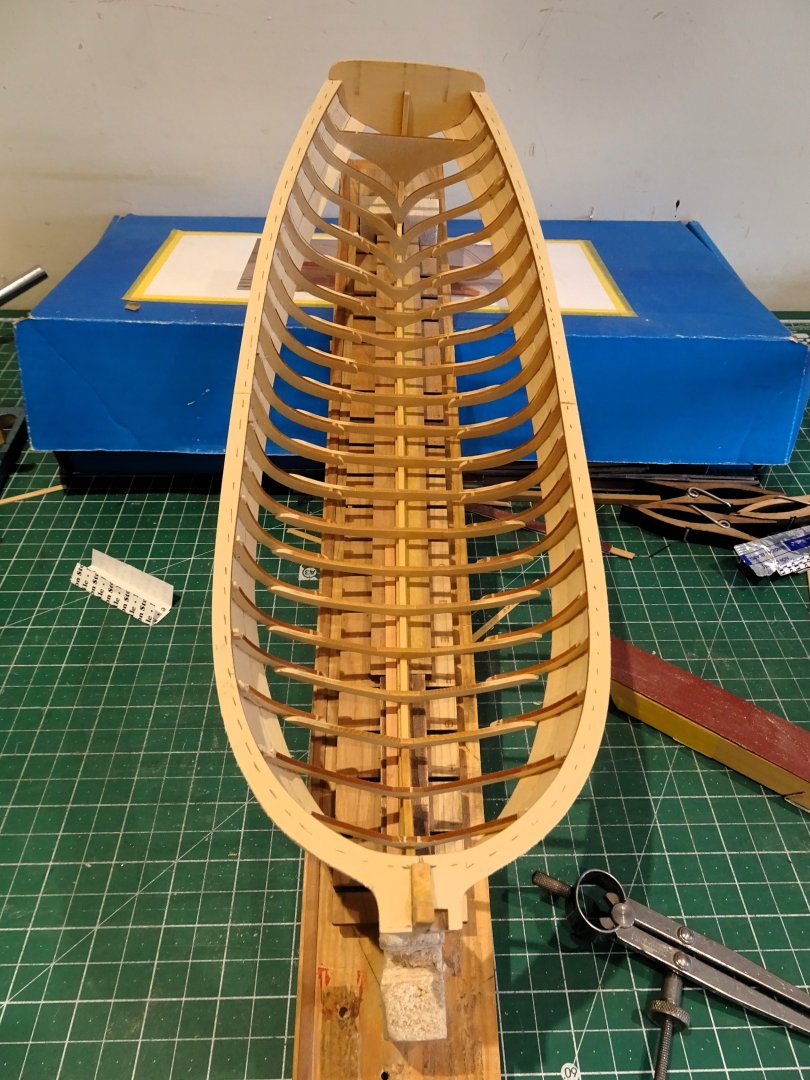
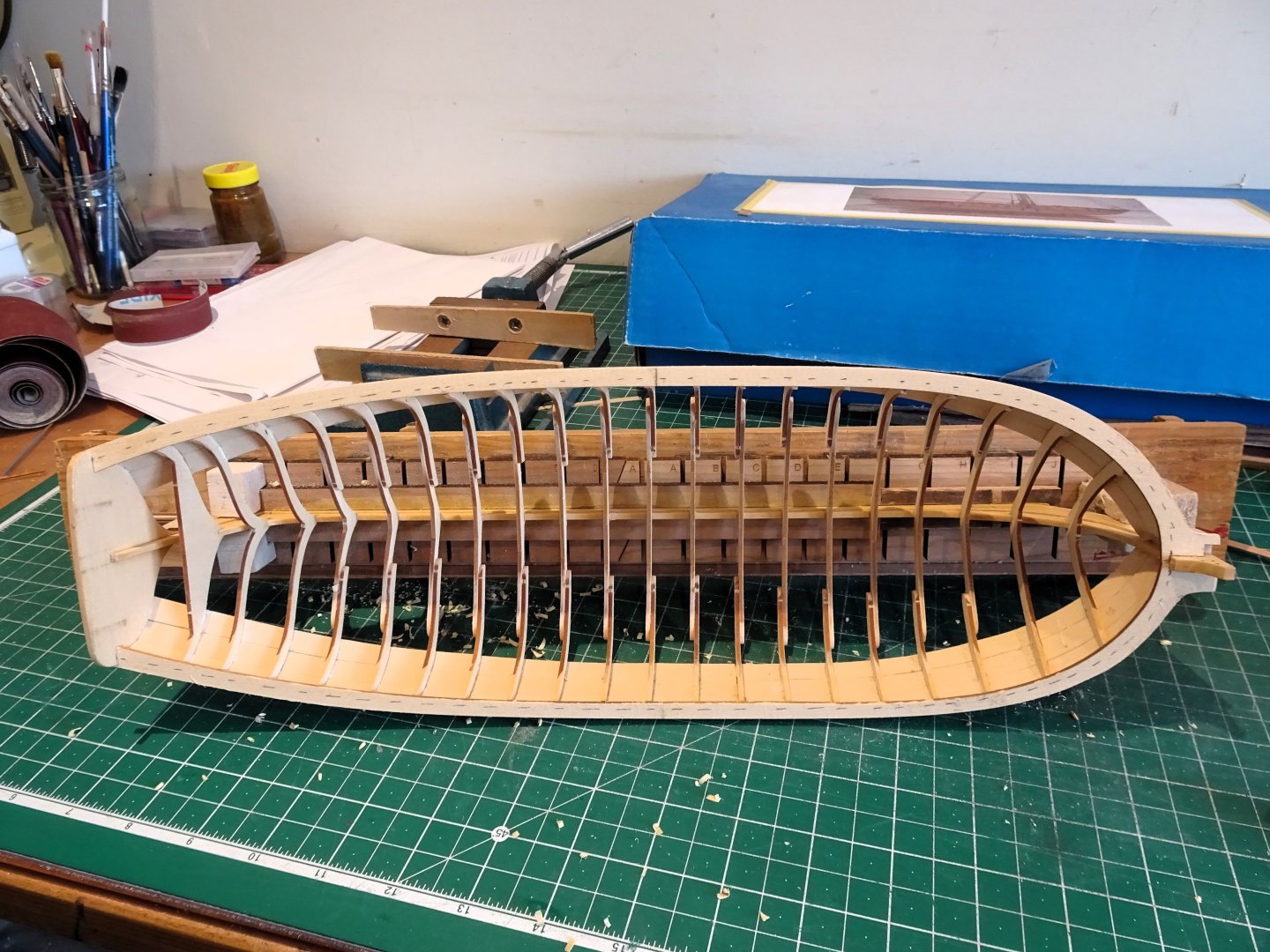
The Journey resumes.
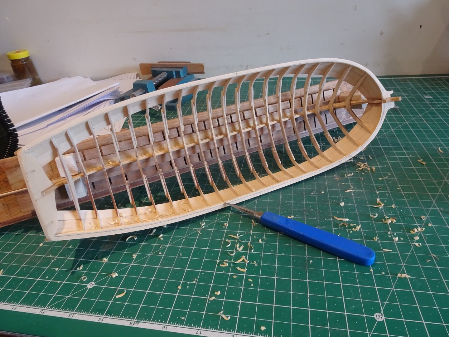
My Medway Longboat has been quietly maturing on the stocks for the past year whilst I have been building Indefatigable.
Time to get back on the job, eh Gromit.
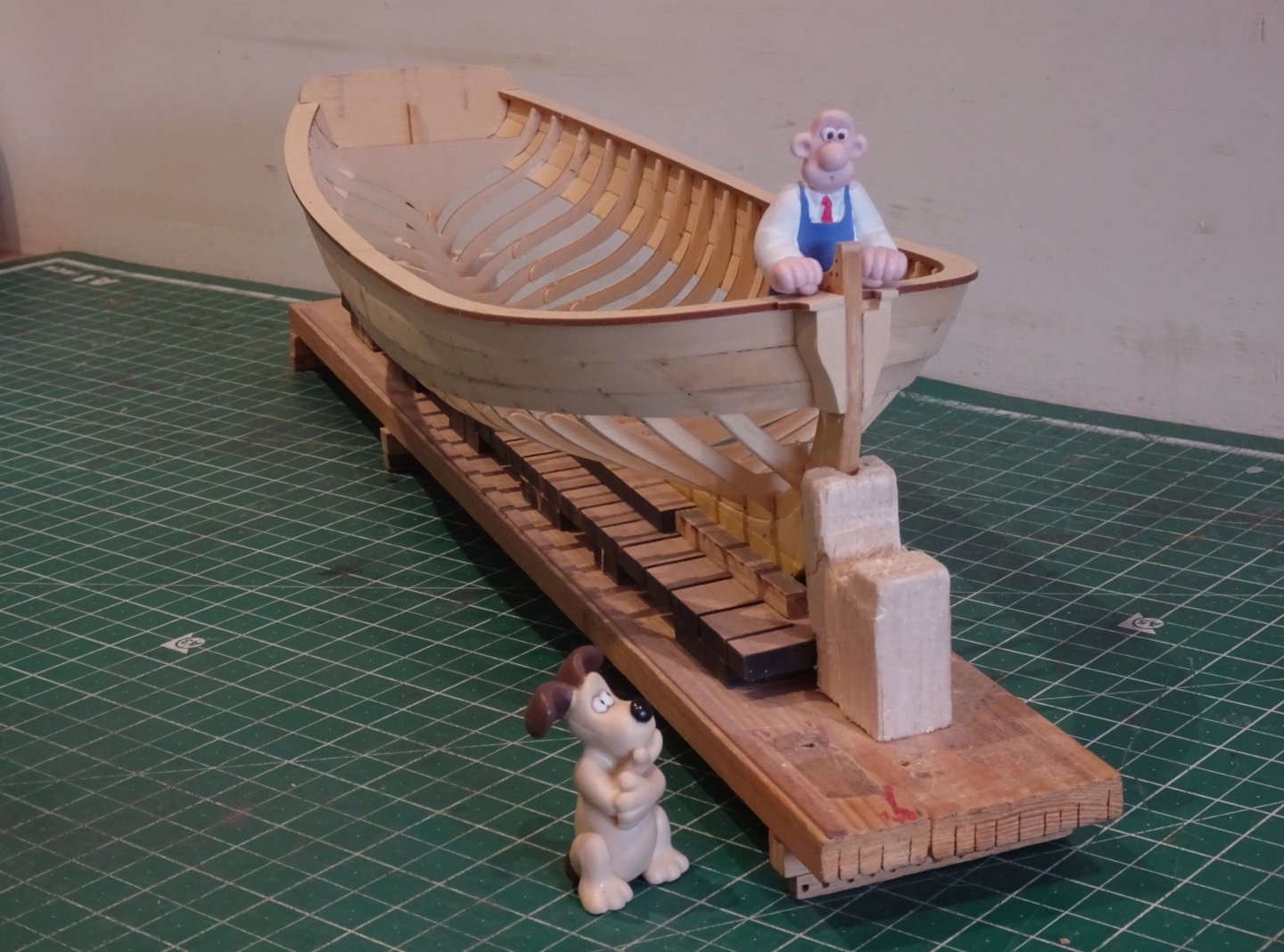
4646
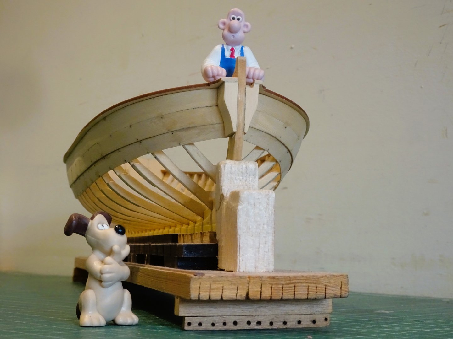
4648
With a year away from the build I need to re-acquaint myself with the current stage before I begin, and a re-read of Chuck’s log and other excellent group builds is where I start.
B.E.
13/05/2024
-
-
The anchors look great Daniel. 👍
I'm pretty picky about fittings but white metal anchors were one of those items I was fairly relaxed about. There were sufficient after-market versions to suit all sizes - from kedge to Best bower, if a full set was required.
B.E.
- Thukydides, Ryland Craze and Glen McGuire
-
2
-
 1
1
-
Post One Hundred and Seventy-five
18’ cutter – completion.
Lifting rings and a mast step are added to the basic kit along with the incredibly tiny thwart knees. Amazing how Chris manages to produce identifiable laser cut pieces this small.

4602
I have gone with a double banked six oared rowing arrangement, mainly because with single banking I would have to cut an oarlock in the wash strake above the sternsheets, and there’s insufficient depth.

4625
I’m not a fan of the kit rudders supplied with this range of boats, comprising a thin central core sandwiched between two brass etch facings complete with straps.
I prefer to make rudders using slightly thicker wood with a vertical grain. For the 18’ cutter I used 1mm Boxwood.
.jpg.4e32b40c95d30a7fc4ab2f829e469b6d.jpg)
For hanging I use the ‘quick release’ method as used on such boats, as seen here on one of the Victory’s cutters.
With this arrangement the pintle is attached to the sternpost with an extra-long pin which allows for easier rudder hanging once the boat is in the water.

4590
Rudders are fairly simple to replicate, as is the hanging, provided sufficiently tiny eyelets can be obtained.

4605
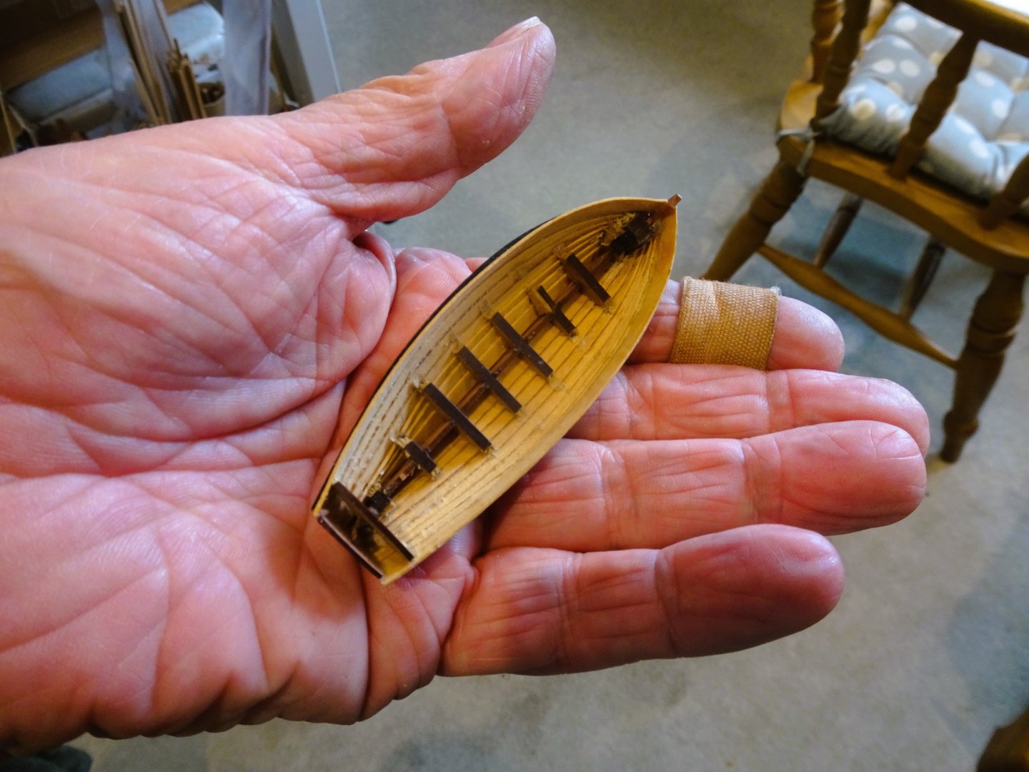
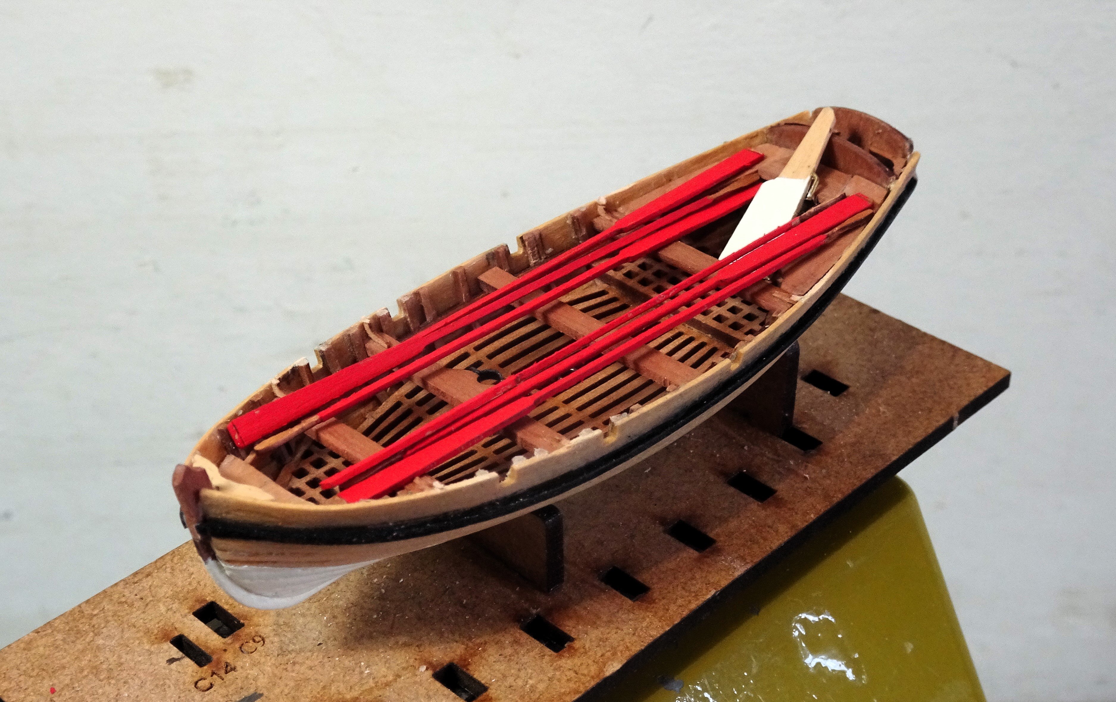
To match the other boats on the skids I have painted the bottom with Vallejo ivory, but otherwise left the remainder of the hull and inboard works bright.

4610
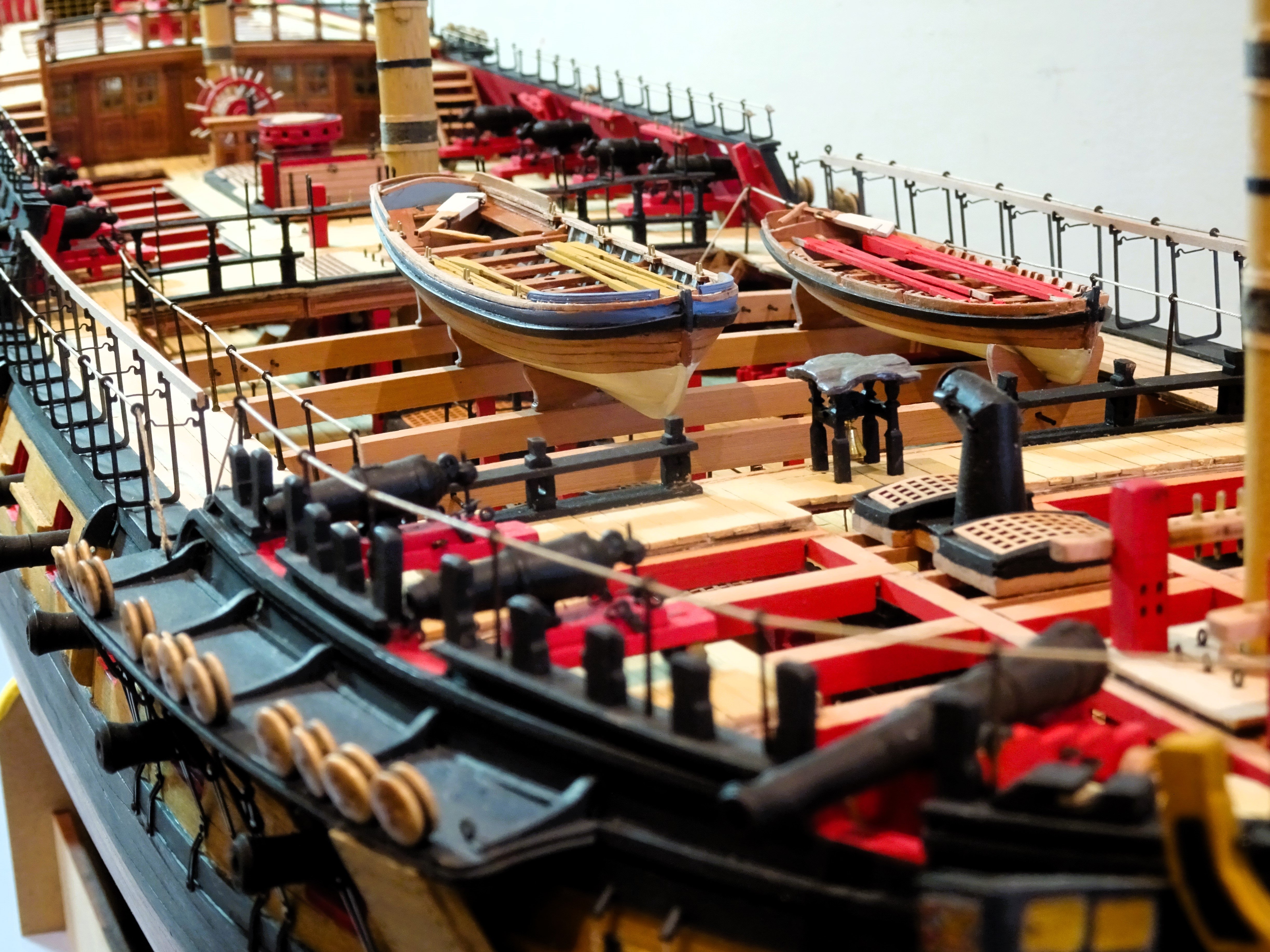
The oars provide the colour element linking to the general inboard works of ‘Indy’
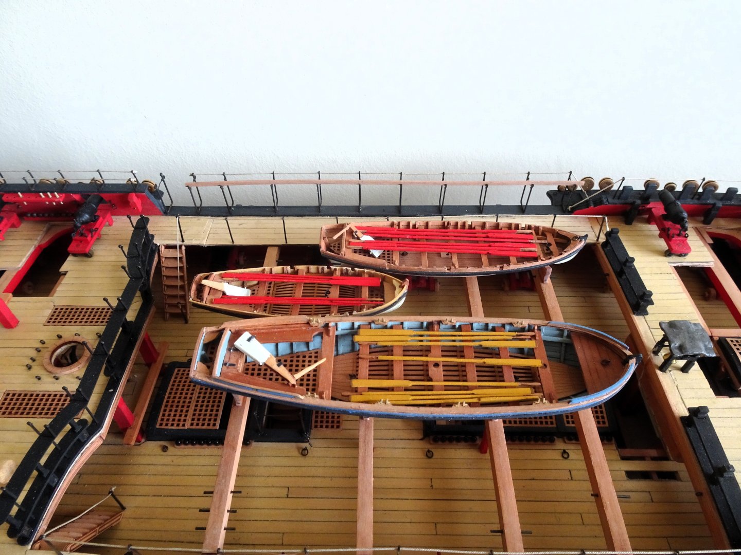
4612
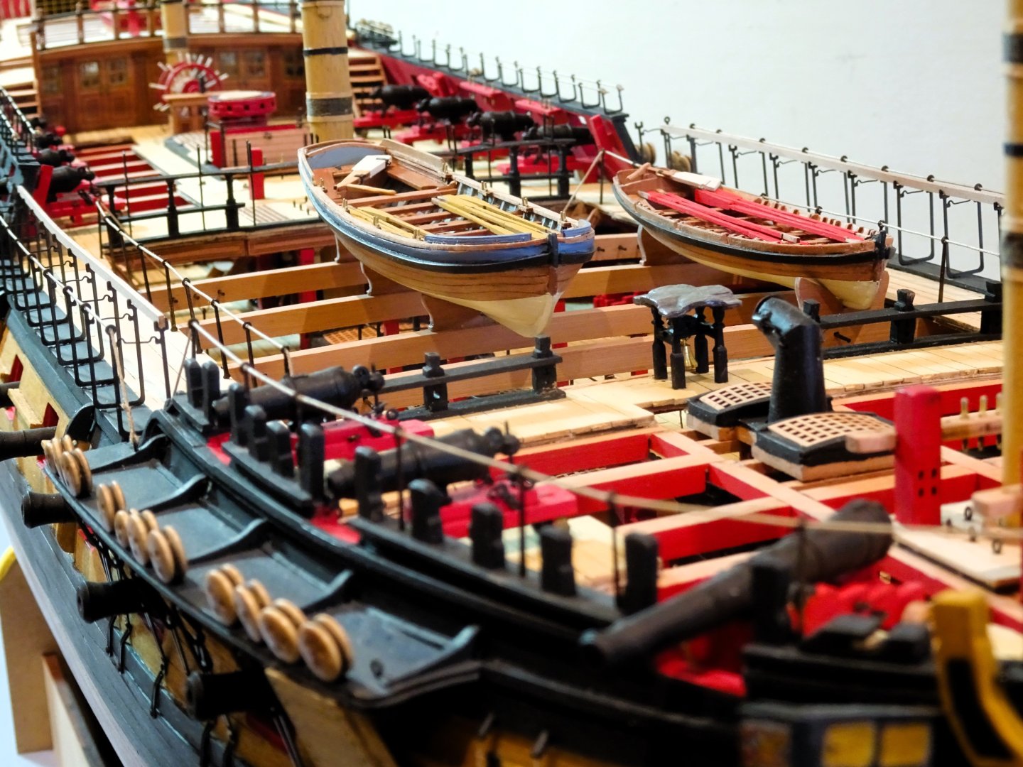
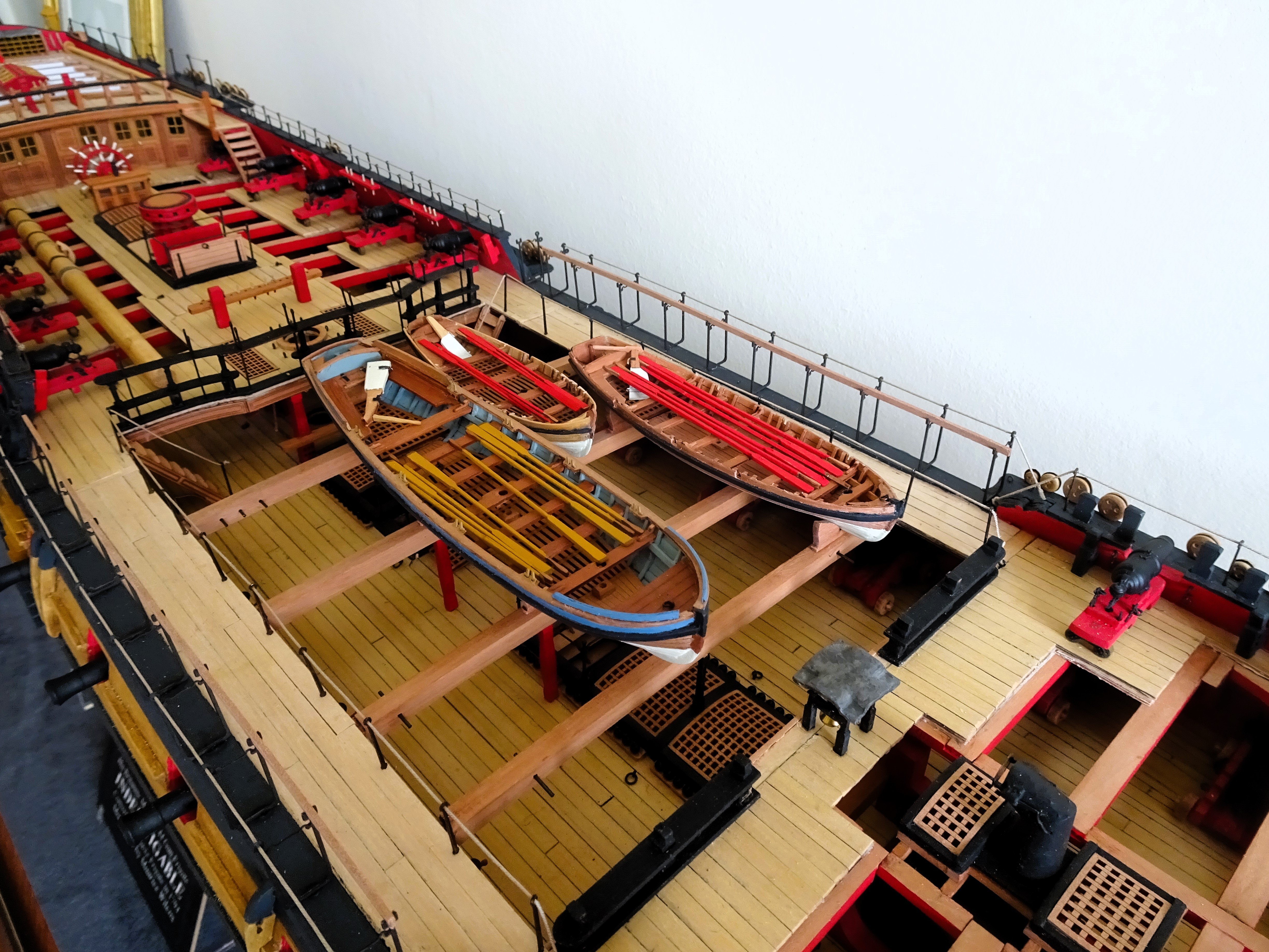
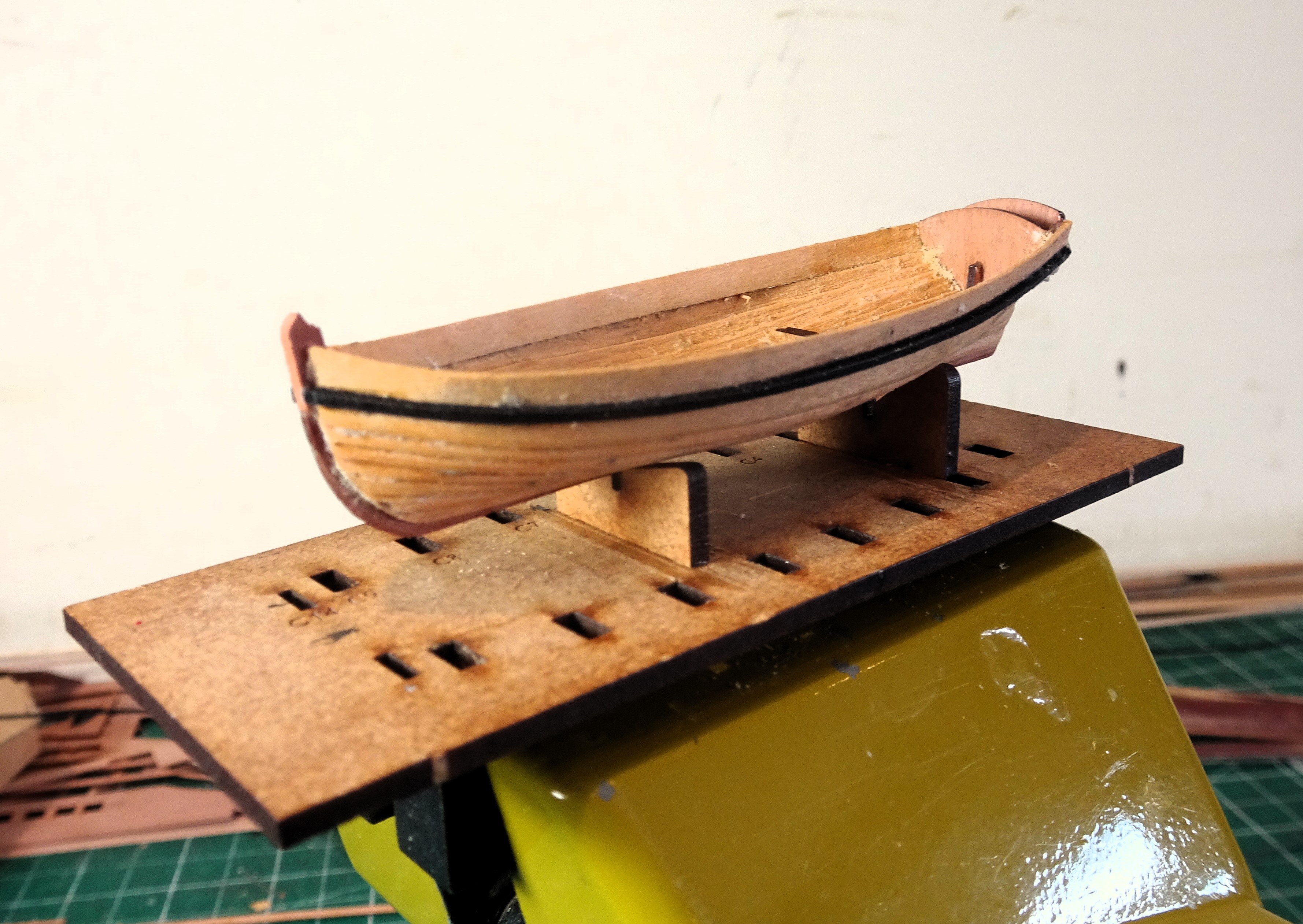
I think this small cutter looks ok on the skids, obscuring little of the gun deck, so I’ll leave it onboard.
It has taken around 8 days to build this smallest of the supplied boats. From around 10” she looks fine to my eye, especially given the scale, but the macro is somewhat less forgiving.🫤
B.E.
10/05/2024
-
Post One Hundred and Seventy-four
18’ cutter – fitting out.
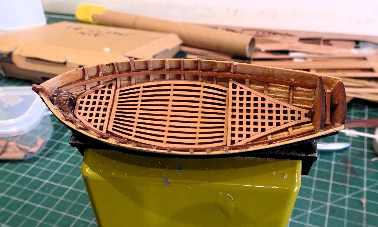
4571
A shot of the gratings and footwalings which are laser cut. A much better option than the brass etch version.👍
These take a little fettling to get them to sit fully down involving bevelling the underside of the parts, and shaving down the frames as required.
The kit sternsheets are combined with the aftermost thwart.
This is an arrangement I don’t like primarily because the grain of the thwart tends to run the wrong way and the set-up makes it more difficult to fit the vagaries of individual hull constructions.

4577
I find it easier to cut away the thwart and make a replacement from spare fret. I have also filled in the open stern area to create an additional bench seat.

4570
At the bow I thought the area looked a little unfinished with the remnants of the mdf construction block on view.
The kit plan (sheet eight) does show a small fore deck in this position but I can’t locate such a part with the 18’ cutter fittings.

4582
This benefits from facing up using spare fret, and the addition of a breasthook above it.
One other puzzlement with the 18’ cutter is the height the thwarts and sternsheets relative to the wash strakes.

4579
They are positioned as per the kit and instructions, but have very little freeboard. It is not a case of fitting them too high as the scale figures show a correct height between thwarts and footwaling.

4580
There is only 2mm between thwart top and wash strake top. This equates to 5” at scale.
Working up from the 1:48 scale drawings of an 18’ cutter in The Frigate Diana AotS book the difference should be around 11”
The new Vanguard resin cutter, what a beauty that looks, shows a much greater depth between the seating and wash strakes which looks more appropriate.
4583
Even so, visually the wooden version is a pretty little thing, and for most casual viewers this disparity won’t even register.

4588
I am fairly happy with the ‘clinker’ look but it does need a good clean-up.
B.E.
08/05/2024
-
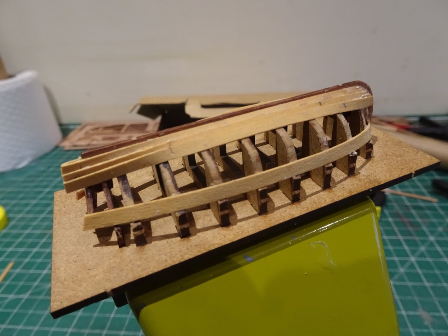
Post One Hundred and Seventy-three
18’ cutter – Jolly Boat
I thought I would have another stab at clinker planking one of these bijou cutters to go with 'Indy'.
My original cutter which sits with Alert was of the older version replaced shortly after I had completed it.
This one is the current and revised version, which includes laser cut gratings and footwalings whereas the original had brass etch versions.
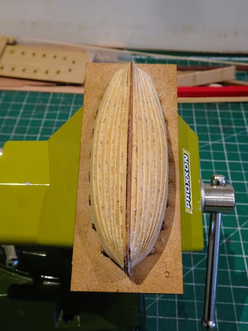
I will be using 3.4mm x 0.6mm Boxwood strip, and of necessity the planking starts at the keel and works up to the Wash strake.

4315
The Garboard is applied first using pva. This is shaped at the bow but is otherwise untapered.

4320
The second strake overlaps the Garboard by 1mm.
In proper practice there is a rebate or rabbet edge along the top of each plank to take the bottom edge of the plank above.
At scale and with 0.6mm board I can dispense with this nicety.
From the second plank above the Garboard I am adding a degree of taper both fore and aft. How much is down to eye and best guesstimate.
 4528
4528
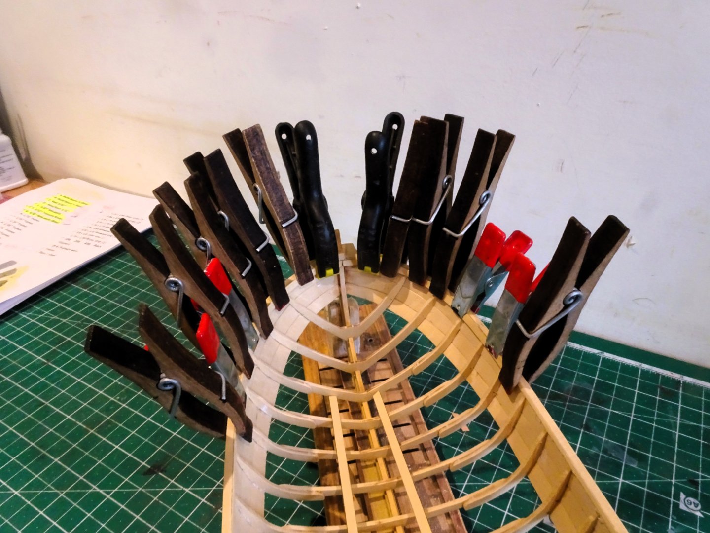
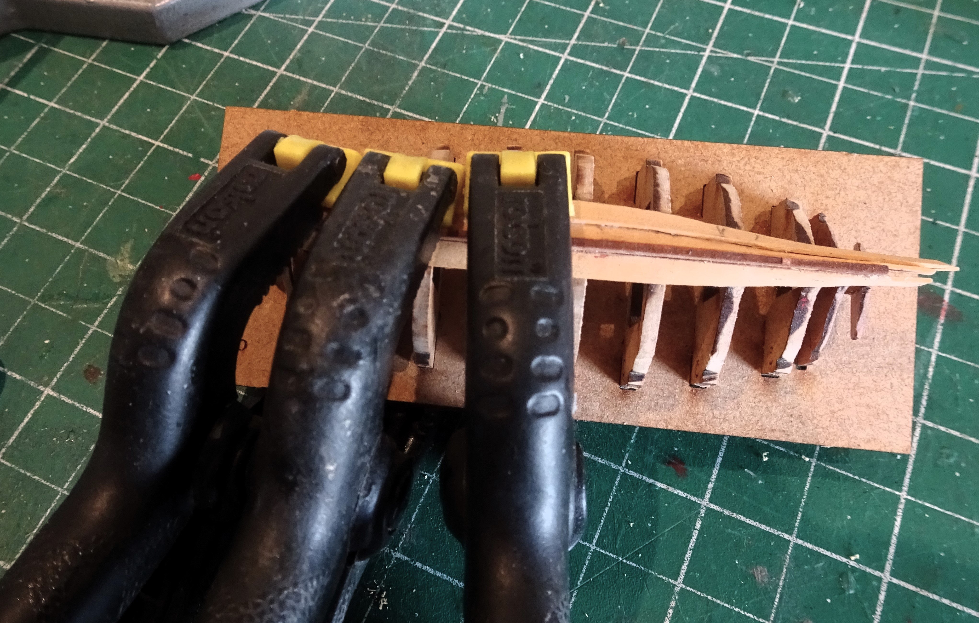
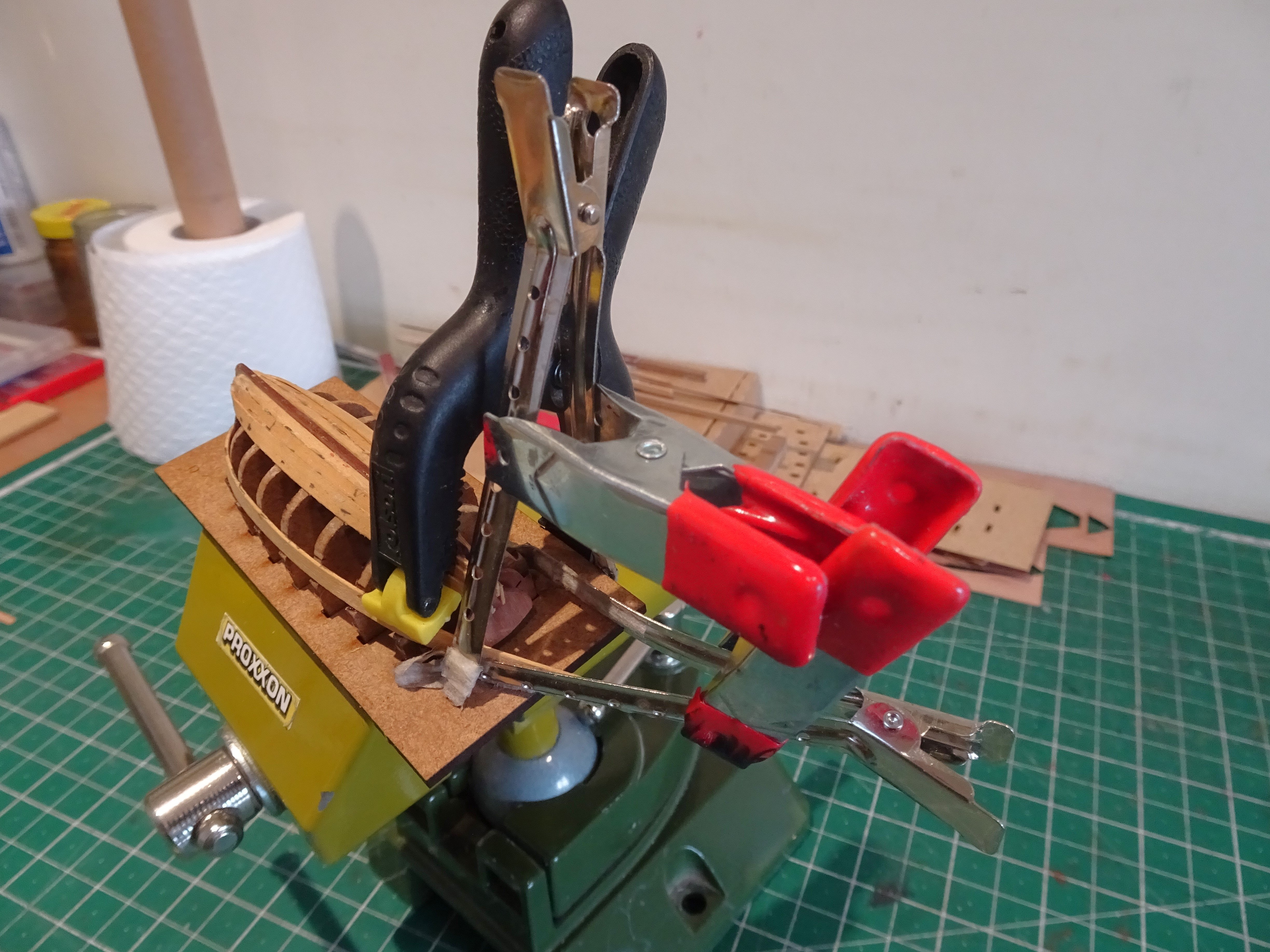
As with all these projects clamping is an issue, more so as the planking rises.
4531
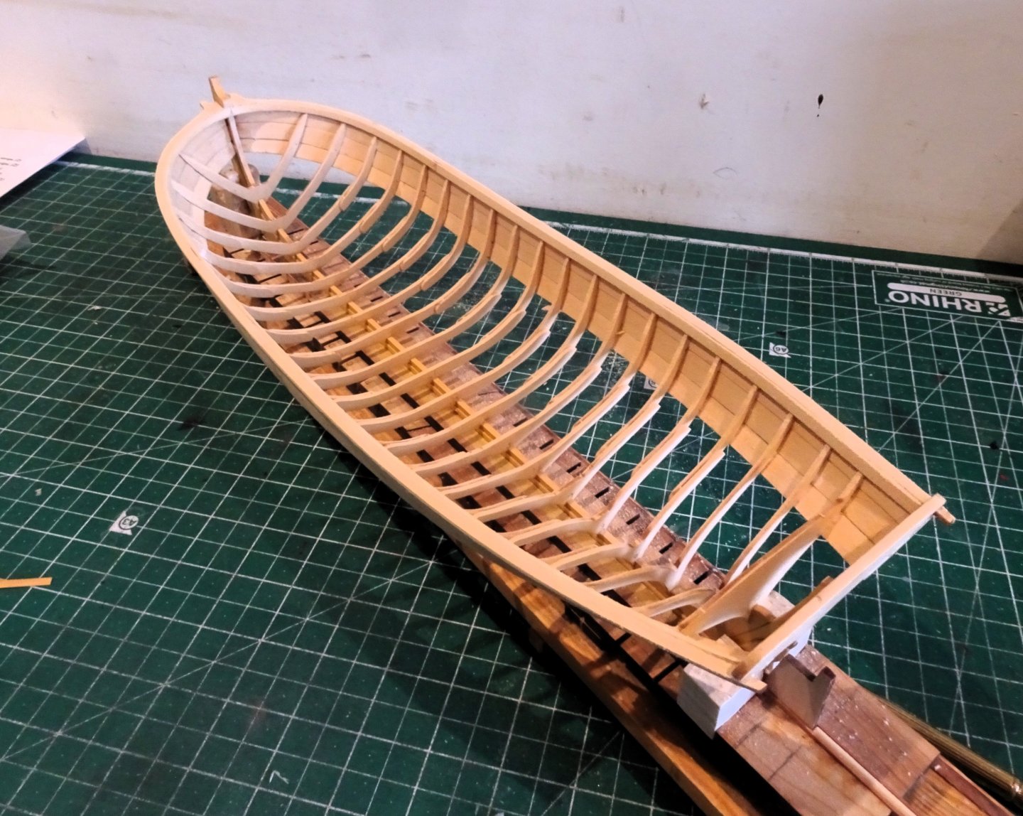
With three strakes added I move to the wash strake. This is fitted untapered into the bow slot.
Twice the stem part broke but repair was effected and once the wash strakes are in place the area is more stable.
4542
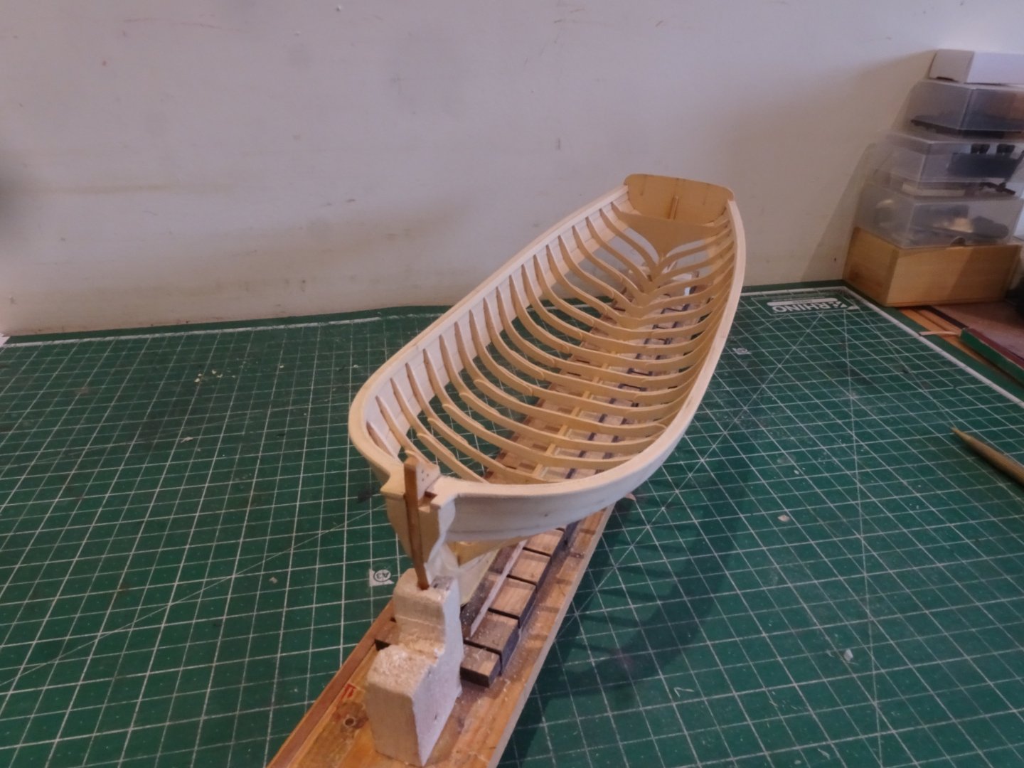
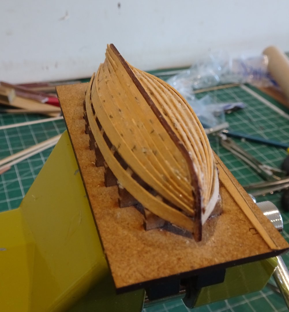
As the strakes are applied the taper increases fore and aft until the final strake fits flush with the lower edge of the wash strake.
4552
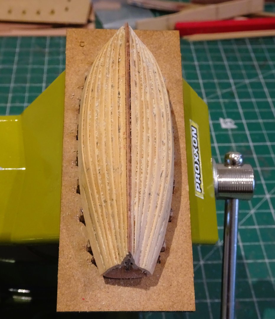
4550
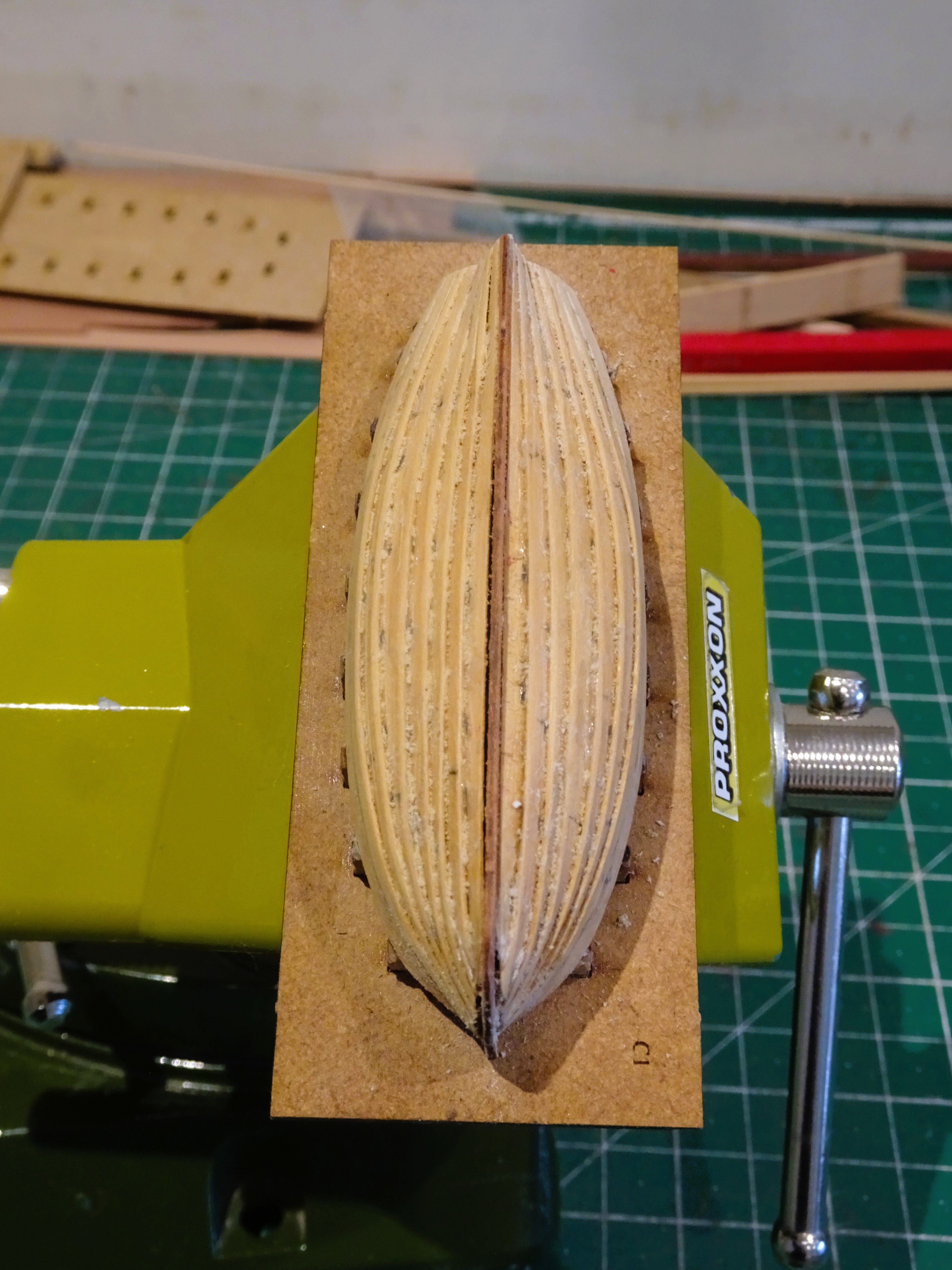
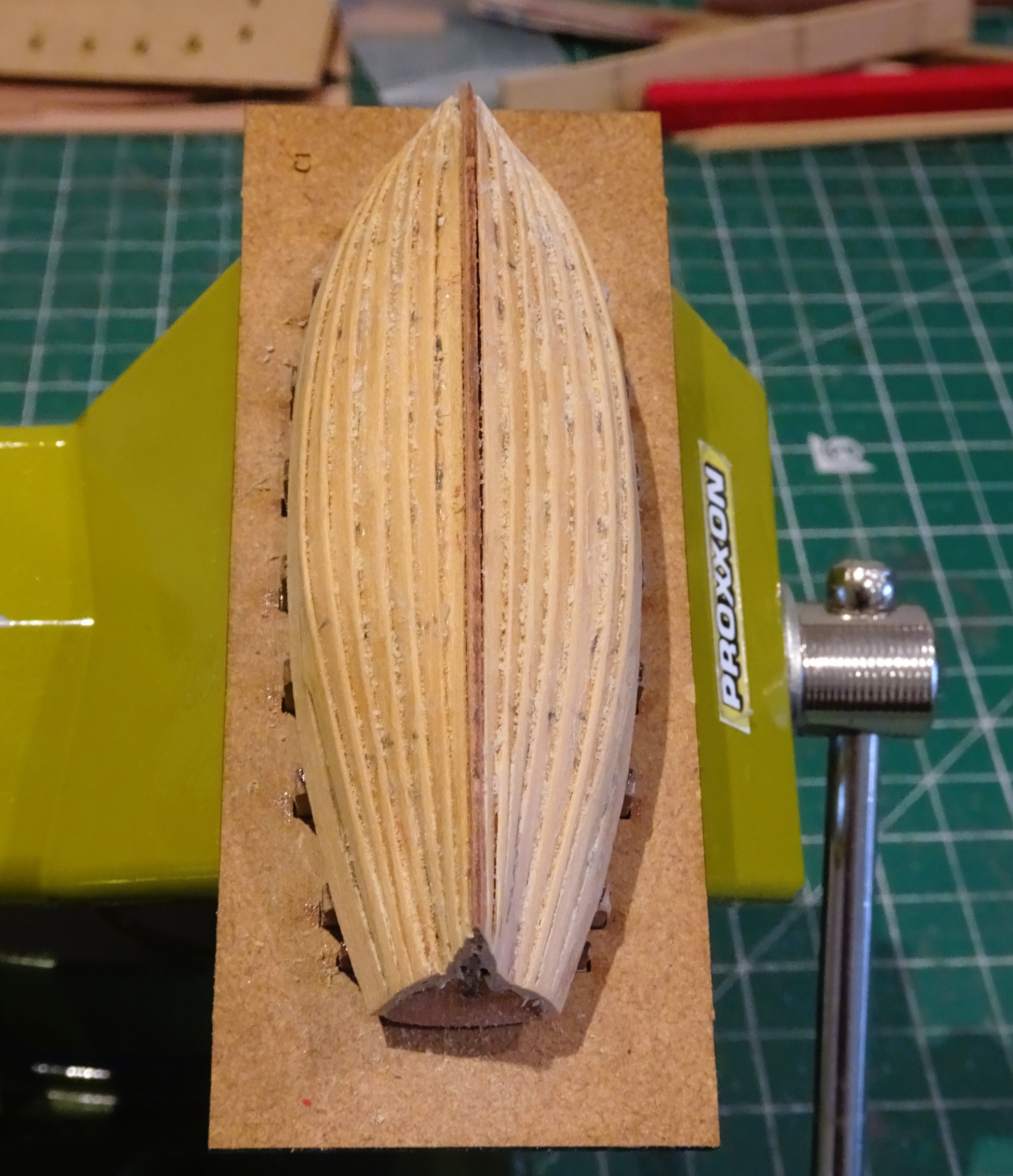
Planking completed in its raw state, but the lapstrakes are clearly evident.

4565
I applied a 1mm square Ebony strip along the lower edge of the wash strake to represent the wale.
It looks broader than it is because top and face edges are not clearly defined on the photo.

4568
4569
There is a satisfaction to be had from completing the hull of this smallest of the boat range, but there is a fair bit of cleaning up required before the inboard fittings are put into place.
B.E.
06/05/2024
-
Good move Chris,
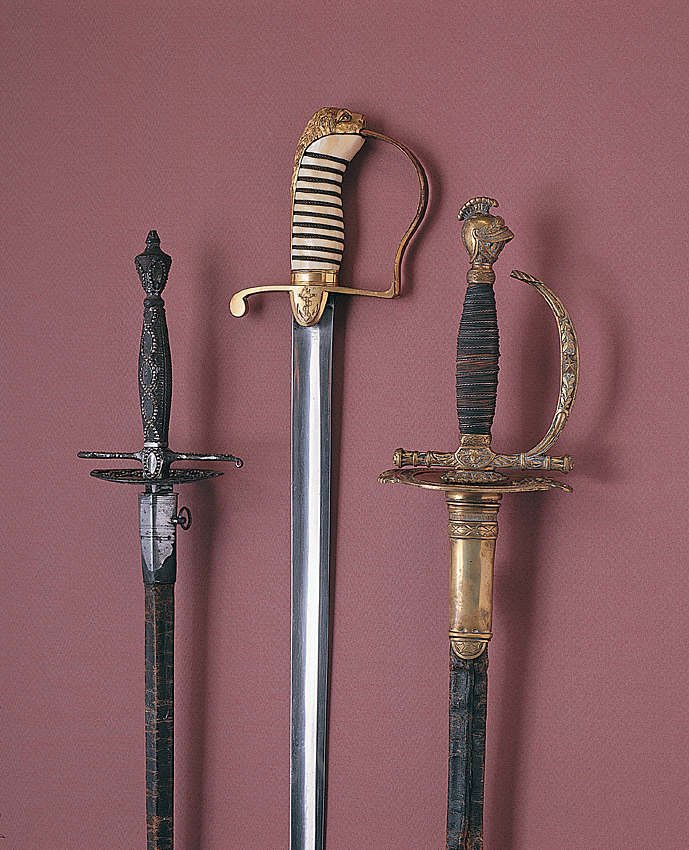
The one in the centre is apparently Nelson's sword found in his cabin after Trafalgar.
The ones right and left are the surrendered French and Spanish swords.
Cheers,
B.E.
-
The detail looks amazing Chris, but I'm intrigued by the style of the sword.
It does not resemble any Naval sword I recall seeing, was it perhaps a specific sword gifted to Nelson?
It rather looks like the sword on the Nelson statue atop his column.
The Nelson Companion edited by Colin White has a photo of the only sword that is known to have been owned by Nelson, and it is of the traditional type.
For the purposes of displaying the figure on a model I think it would be safer to include a Naval pattern sword.
Just a thought.
B.E.
- thibaultron, hollowneck, cotrecerf and 2 others
-
5
-
-
I find it very absorbing how you deal with the trials and tribulations of model ship building, I just love your stuff Nils.
Regarding the paint flaw on the s/b side, I obviously can't tell how it looks in reality, but from the photo it crossed my mind that some modellers would work very hard to achieve that effect on a hard worked light ship.
Regards,
B.E.
- Mirabell61, mtaylor, Canute and 1 other
-
4
-
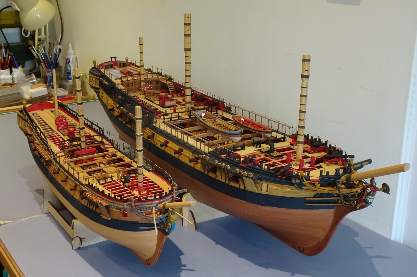
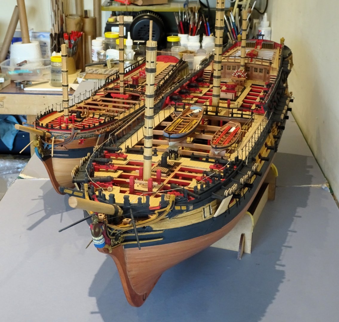
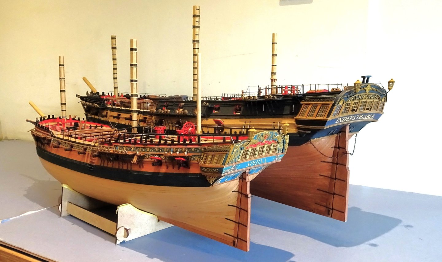
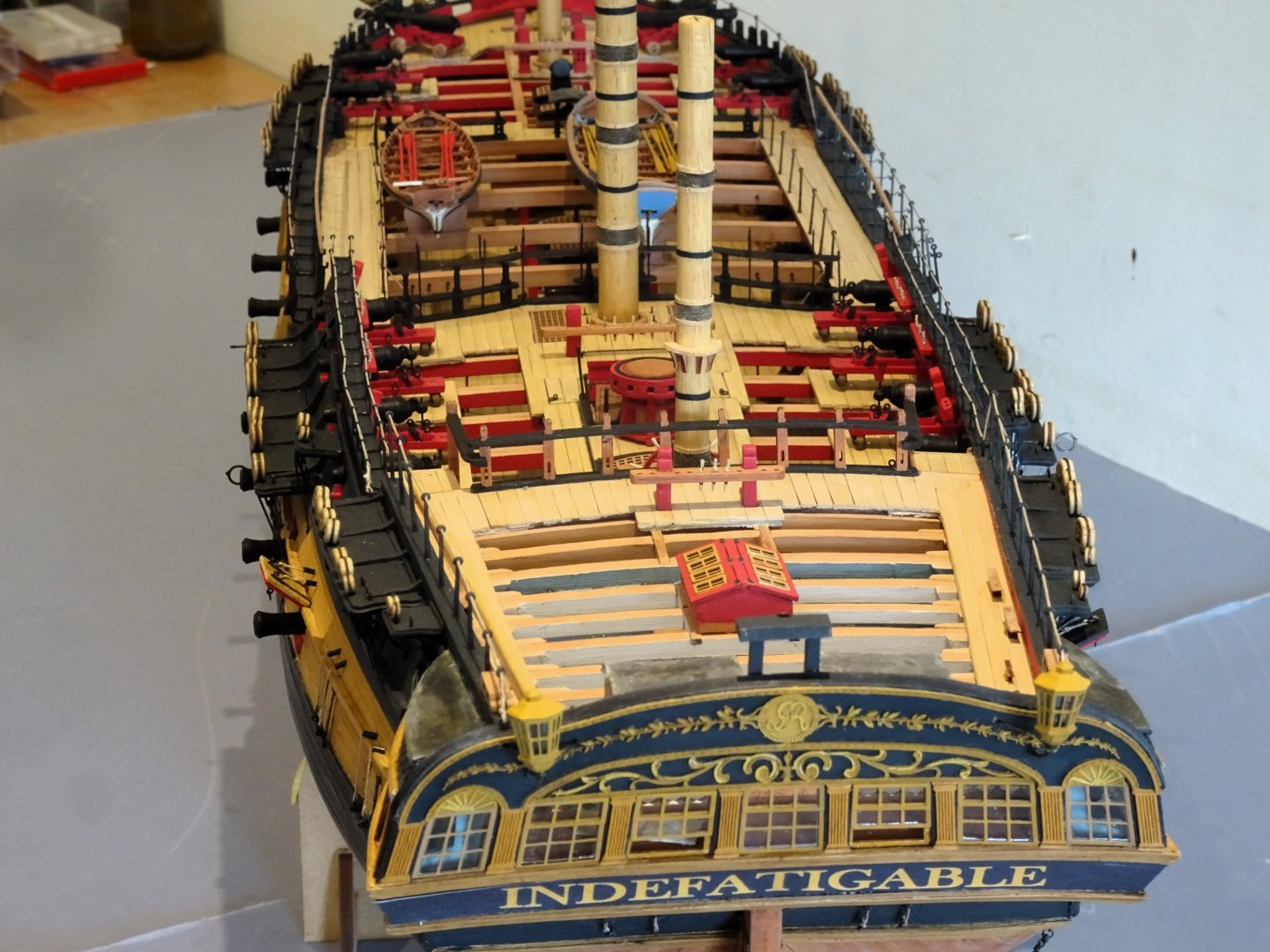
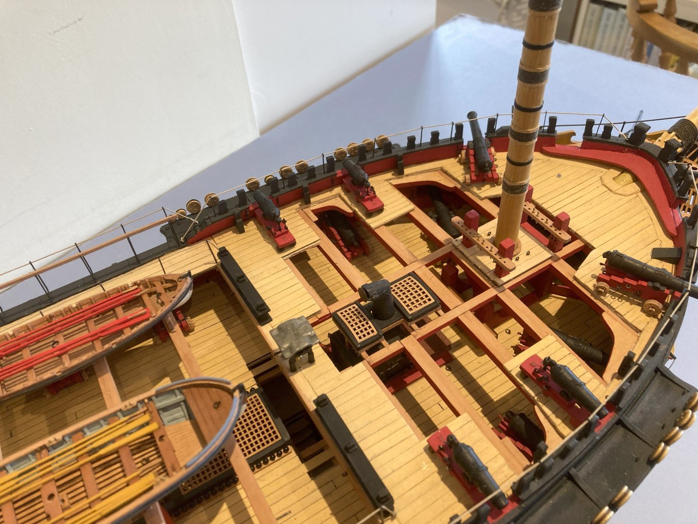
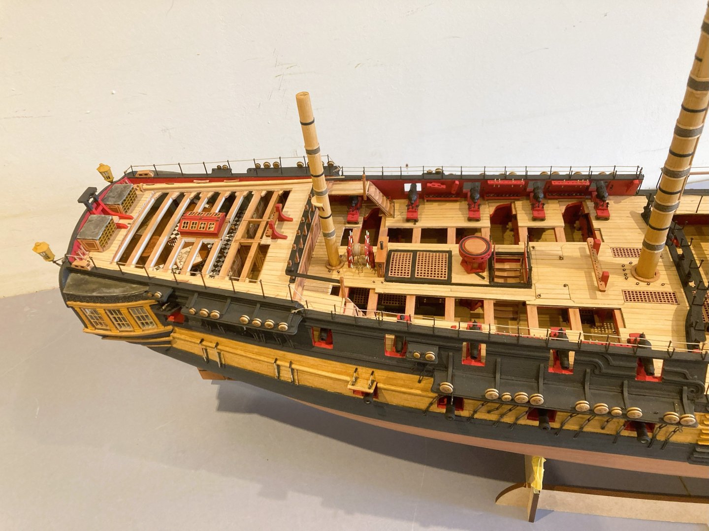
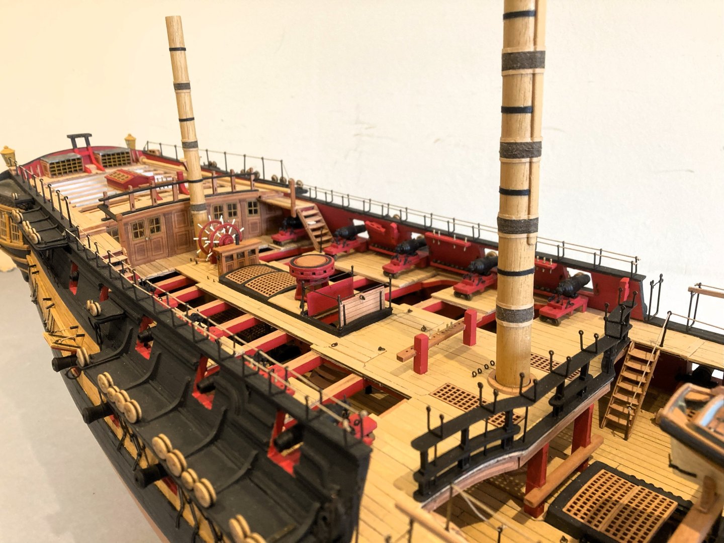
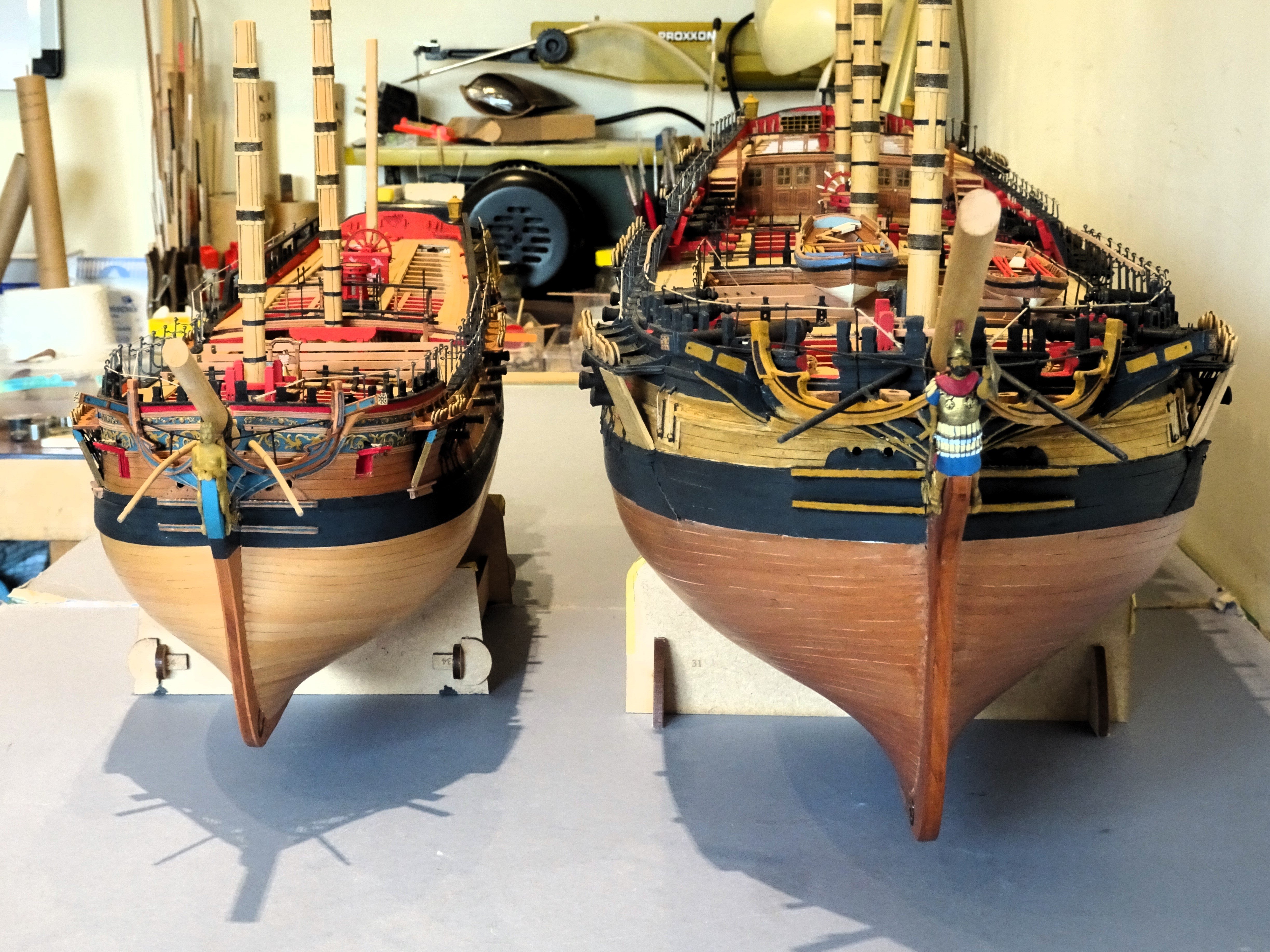
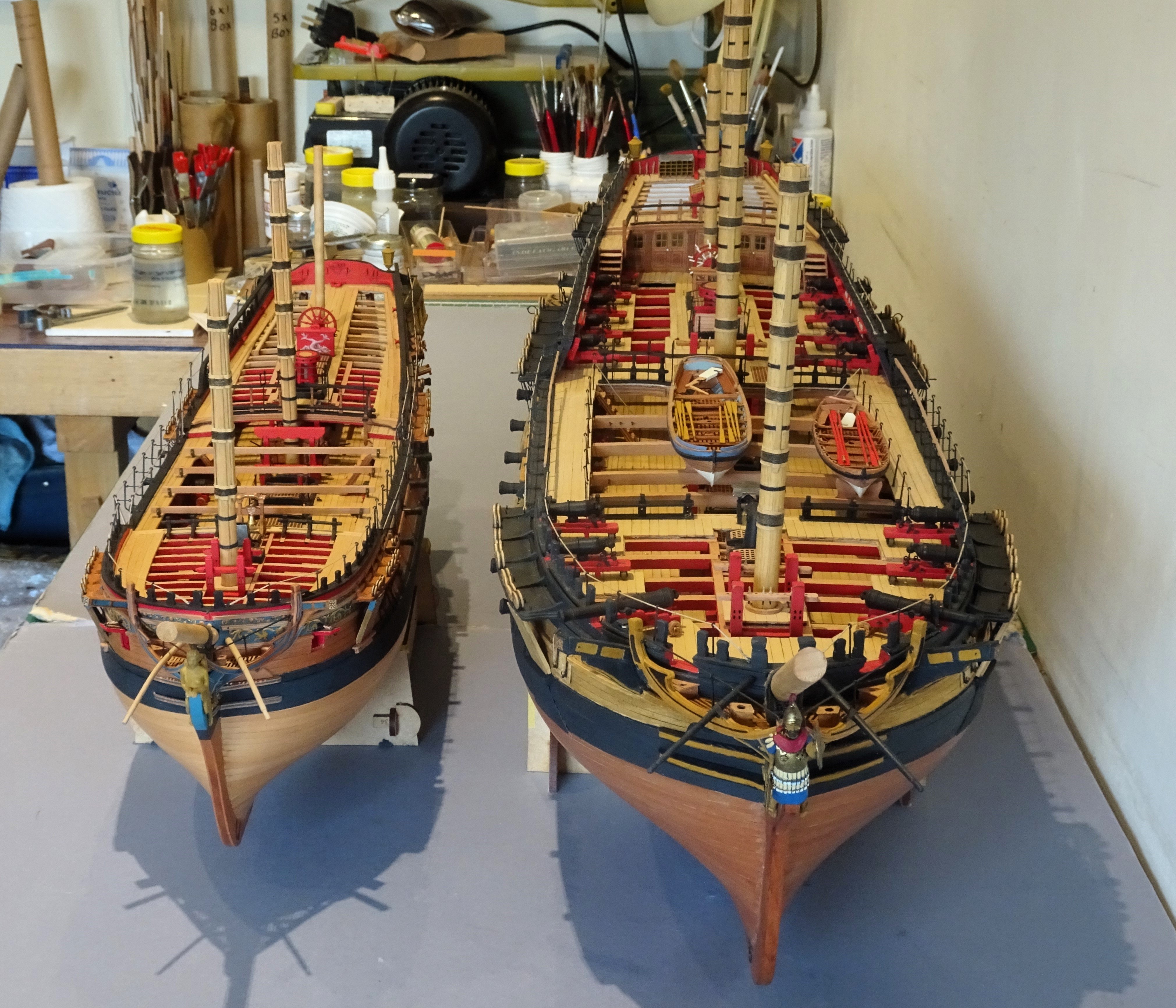
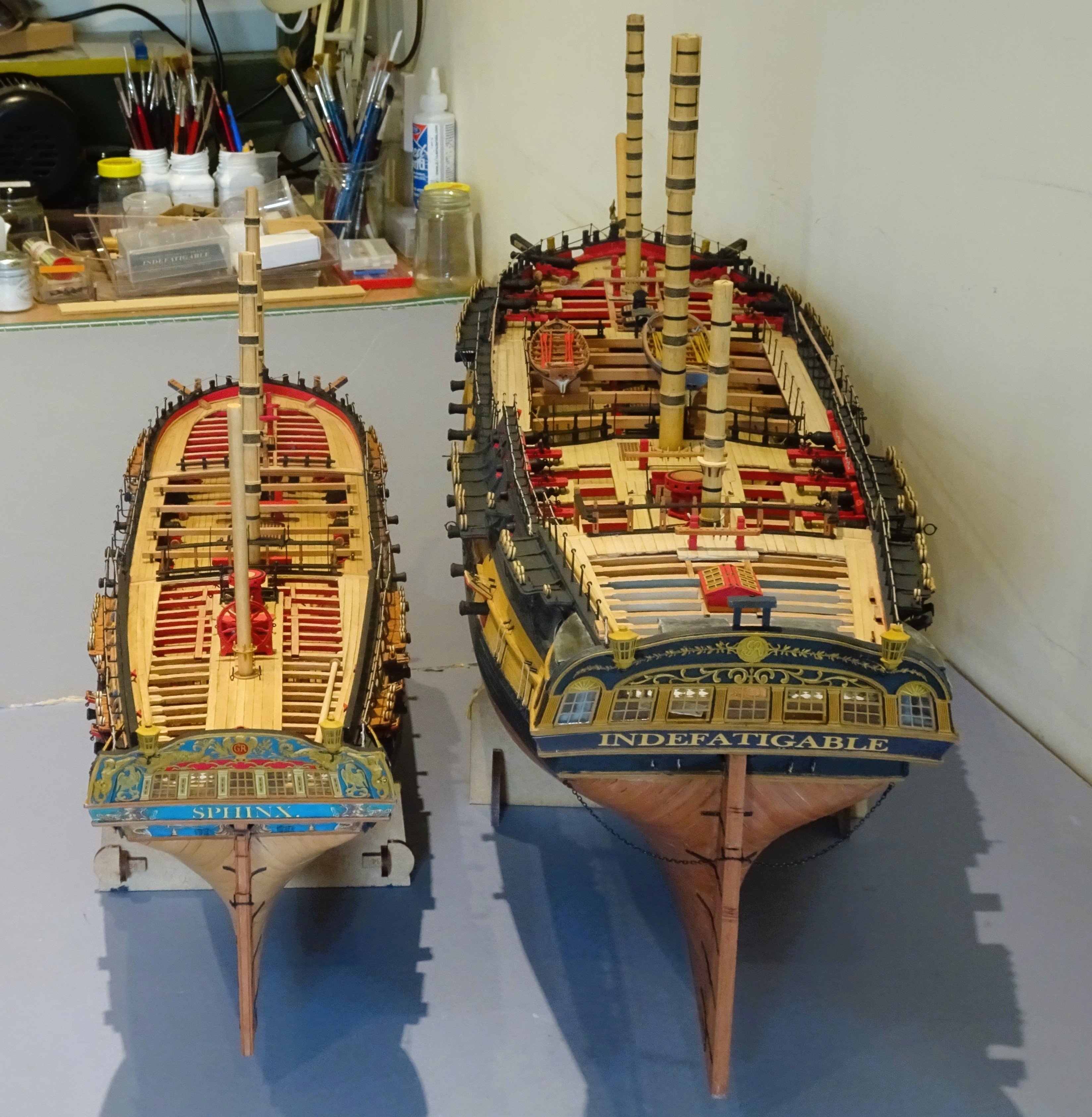
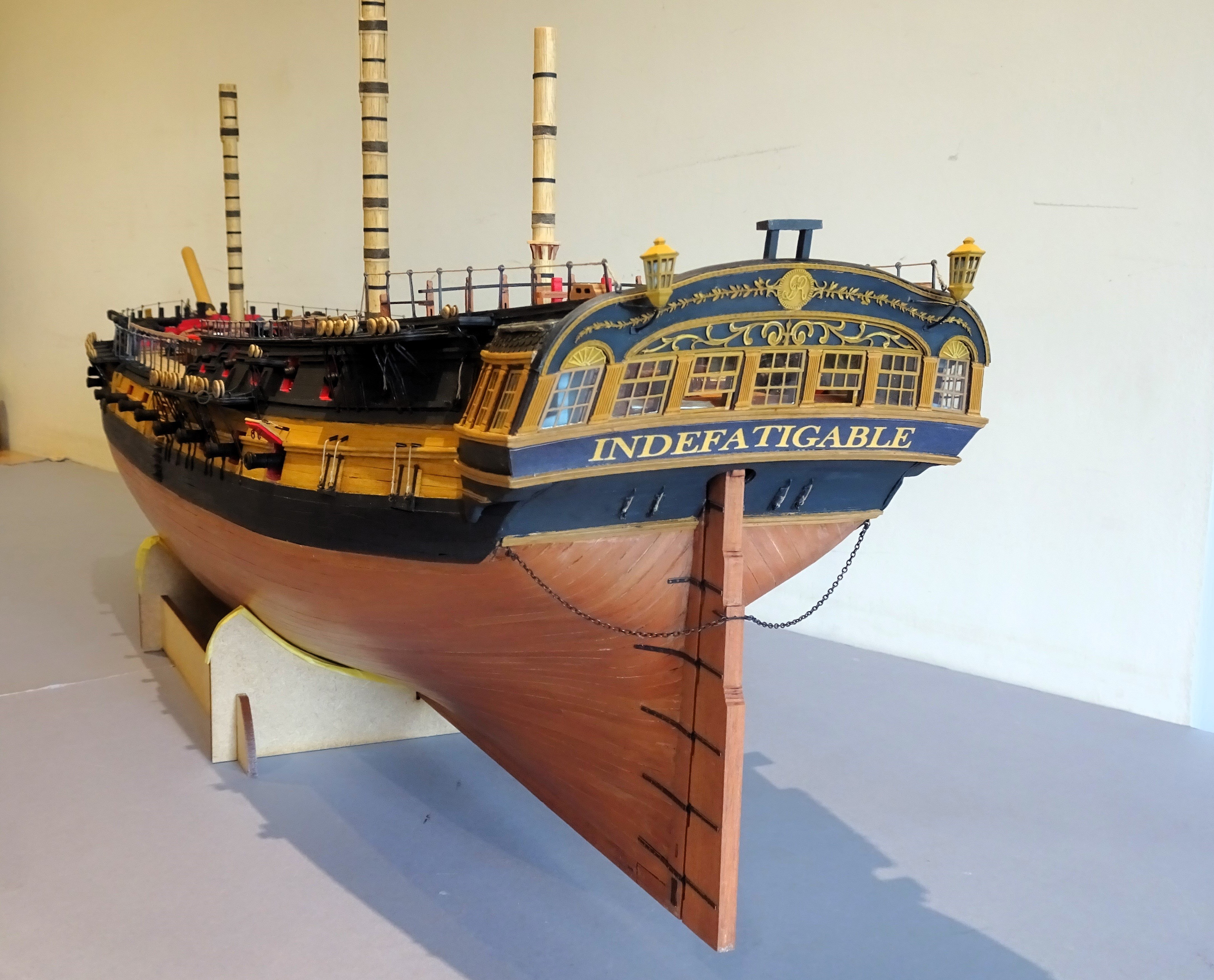
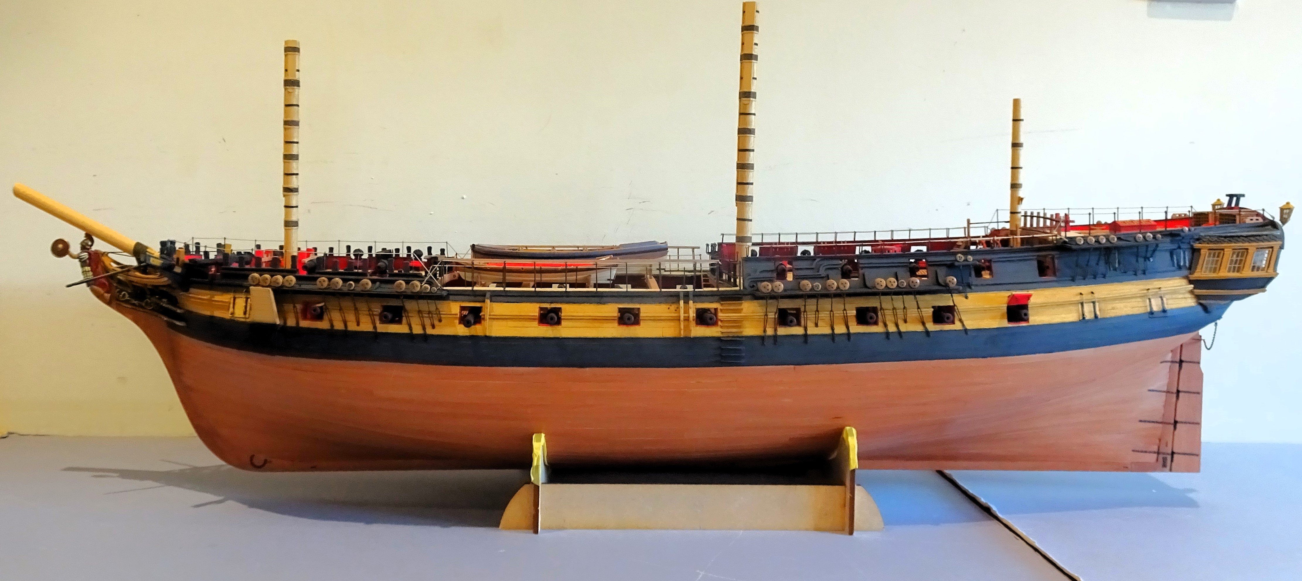
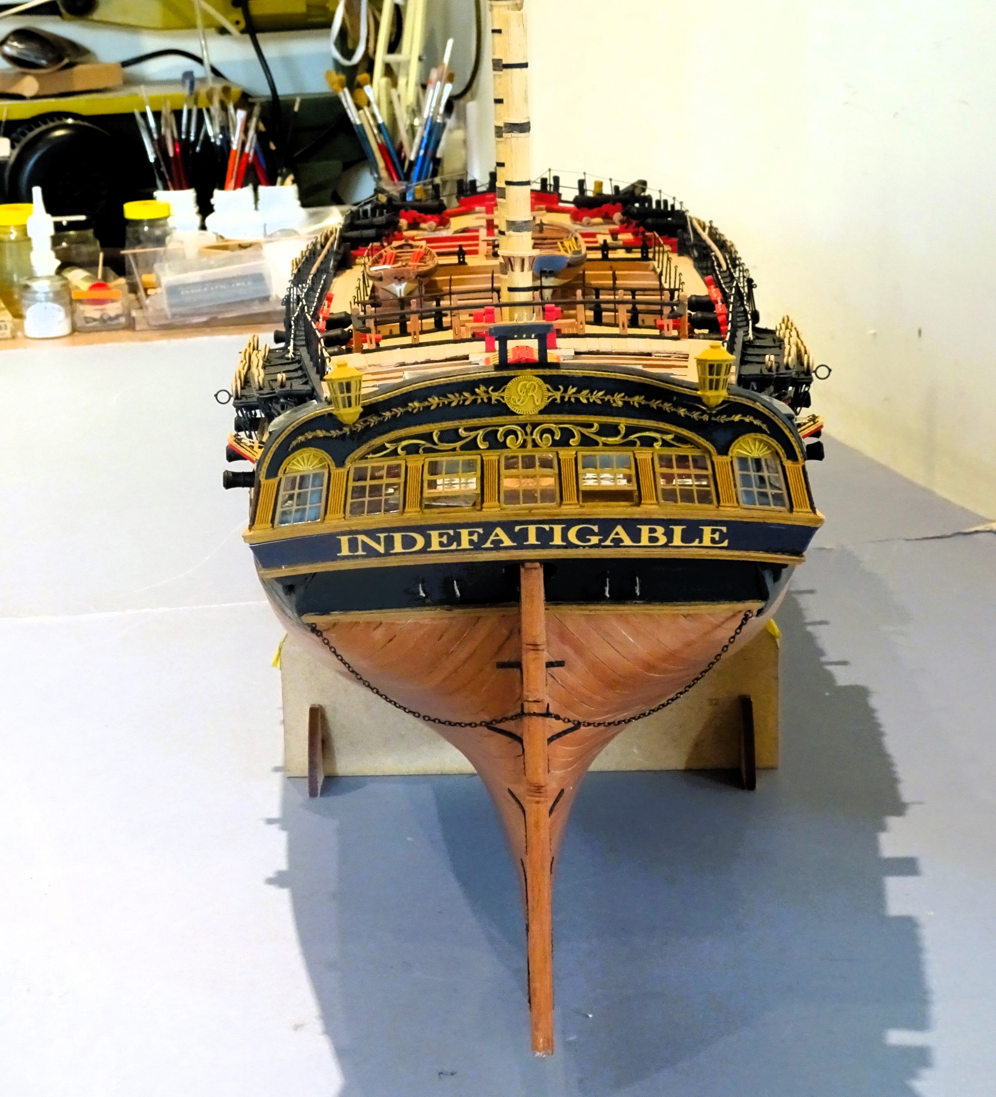
Post One Hundred and Seventy-two
Sphinx and ‘Indy’
I thought members may be interested to see the comparison between Chris’s two premier kits, Sphinx and Indefatigable.
They sort of represent the alpha to omega of British frigates.
Sphinx, the bijou 9 pounder vessel, and ‘Indy’, the pocket battleship of her day, carrying 24 pounders supplemented with 42 pounder carronades.
I recall that when I built Sphinx I thought she was quite large, when ‘Indy’ arrived I thought I’m going to need a bigger bench!
04505

04506

04507
04508
04512
05413

05414
04517
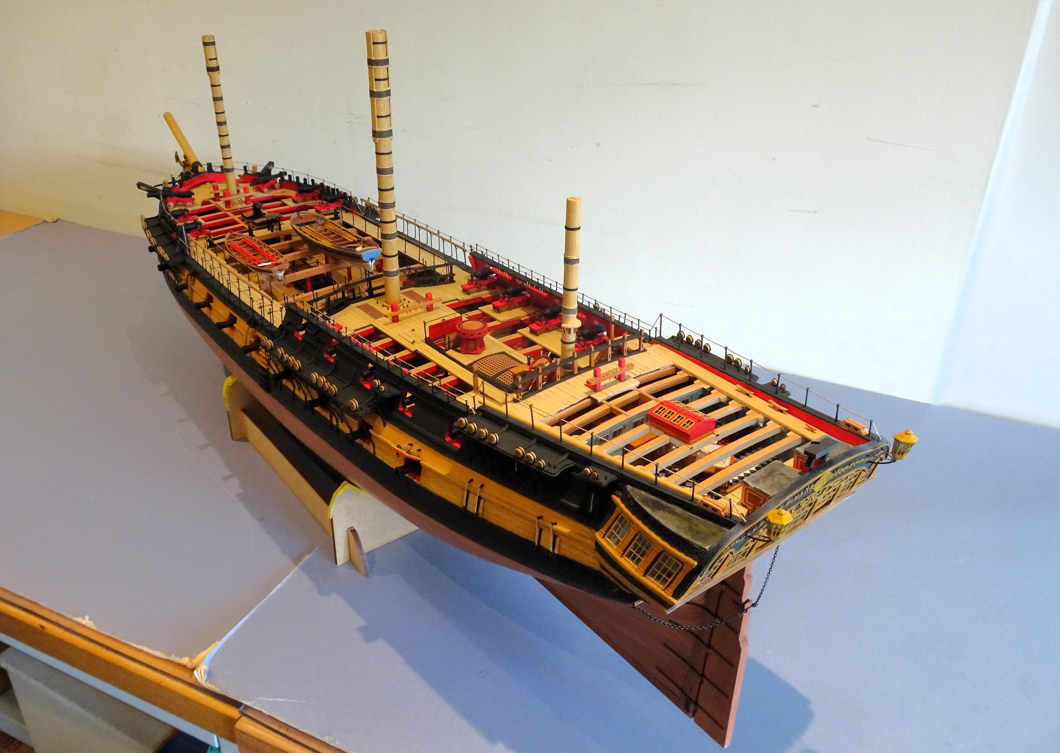
If a large statement model is required ‘Indy’ is a good choice, but if masted and fully rigged she will take up a lot of room.
Built Navy Board style she is still a heavy model and a glass case even with reduced height and width adds considerably to the weight.
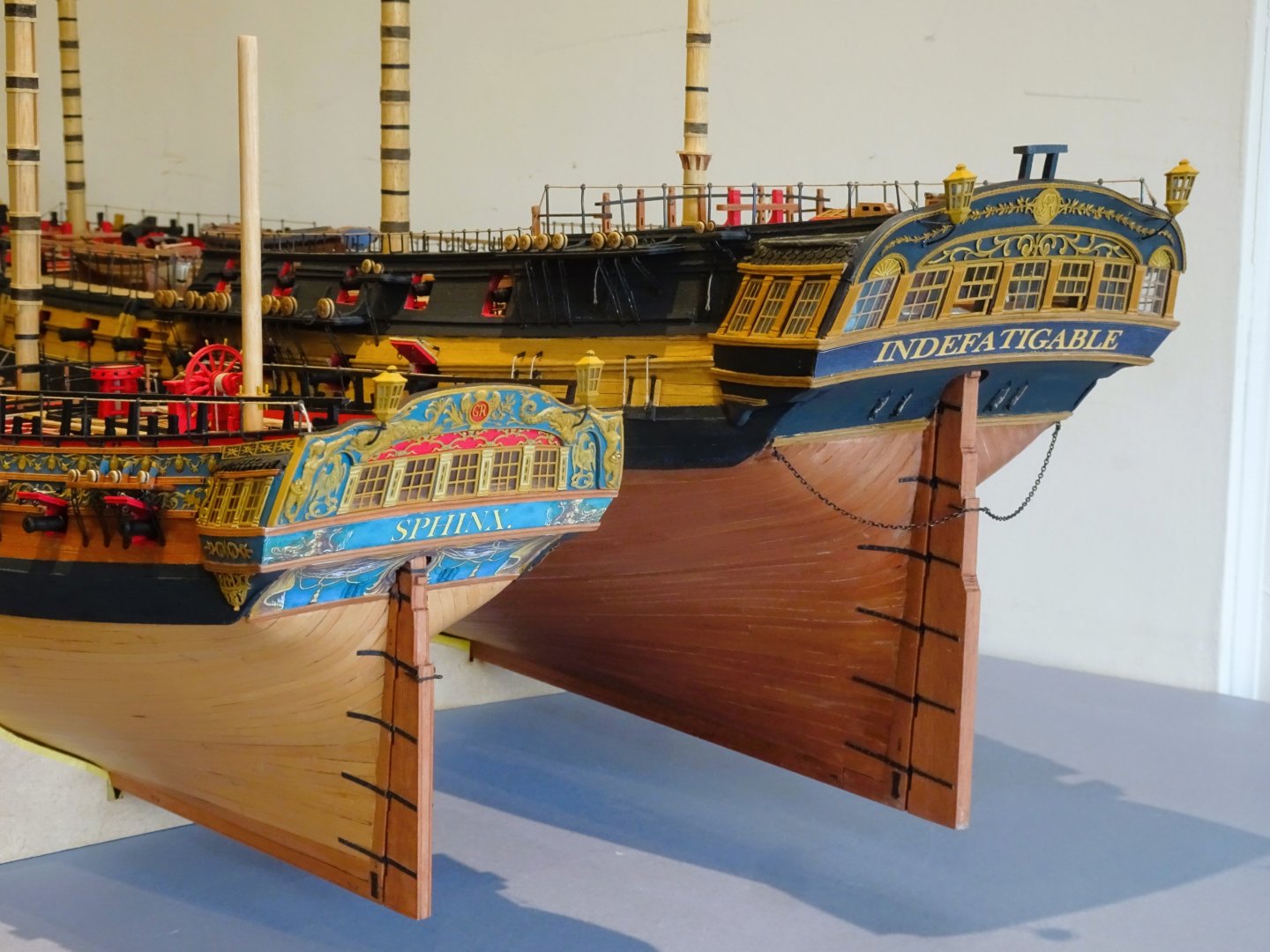
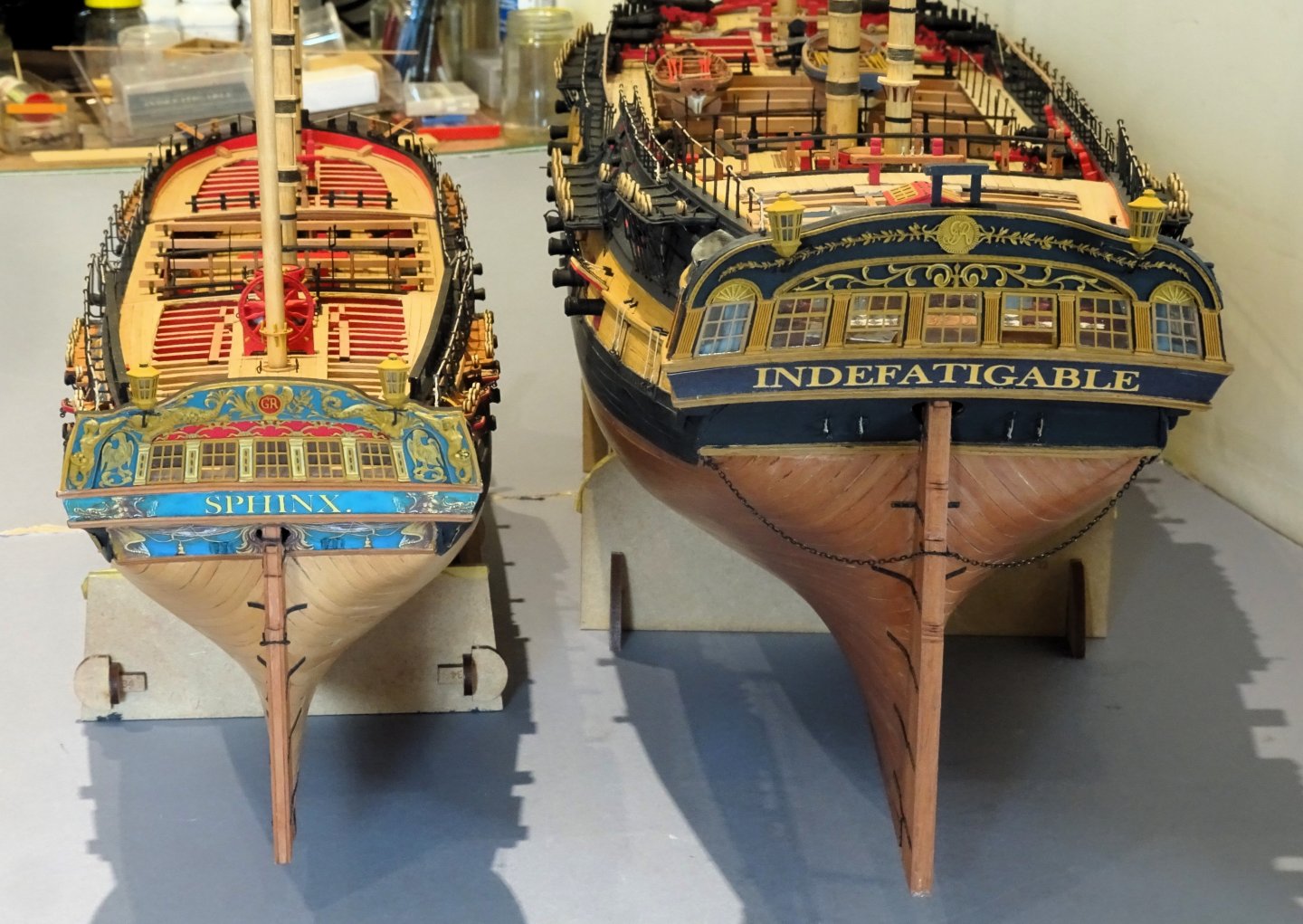
Sphinx is certainly of a size more amenable to a domestic setting; a pretty little frigate that appeals to my deeper affection for the more decorative vessels of the 18thc. before austerity took over as the expensive Napoleonic wars ground on.
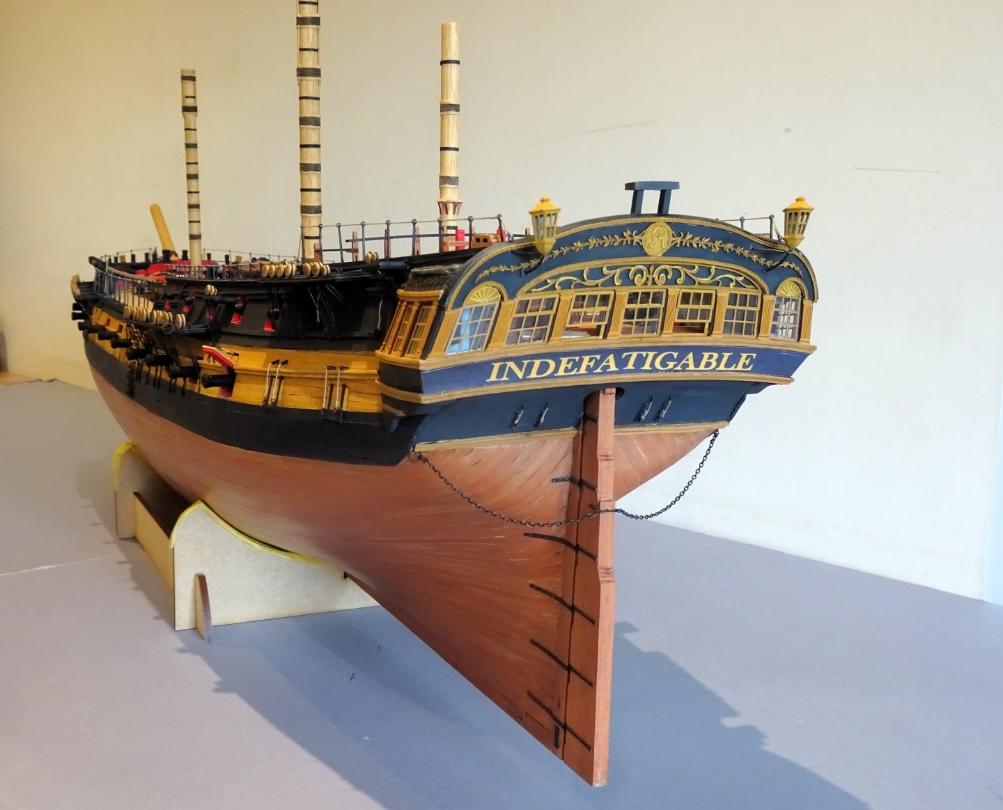
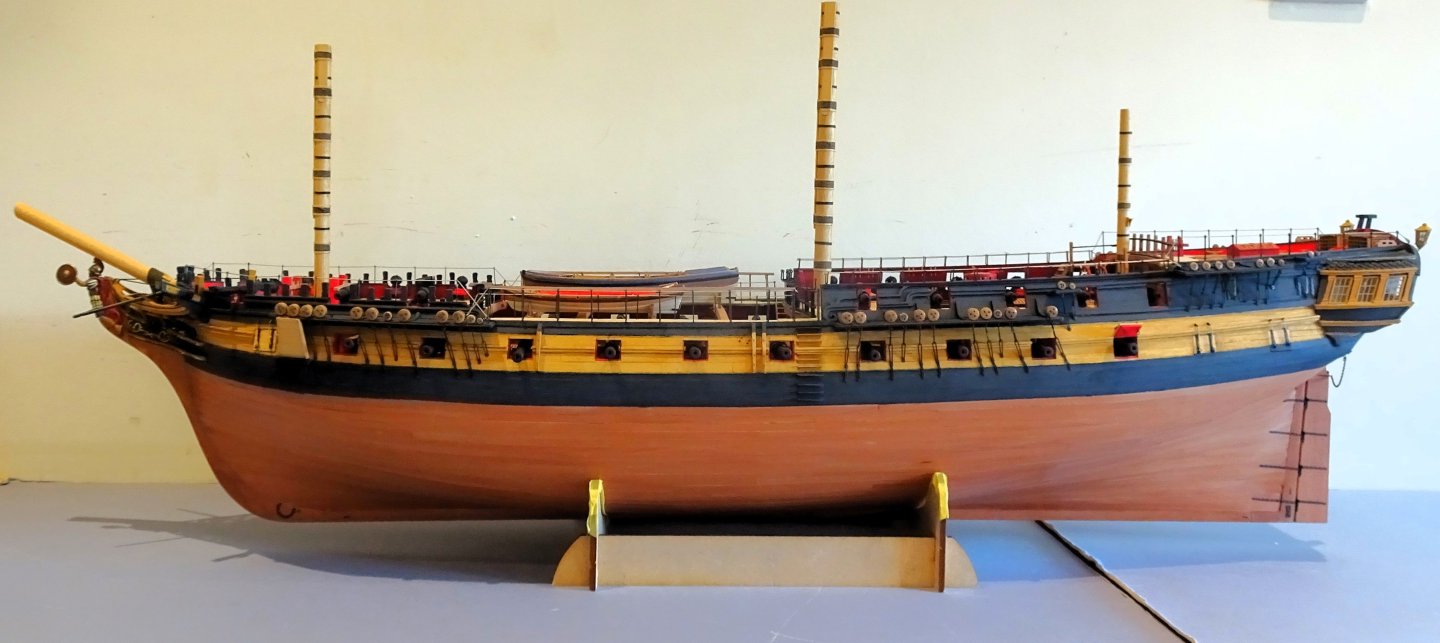
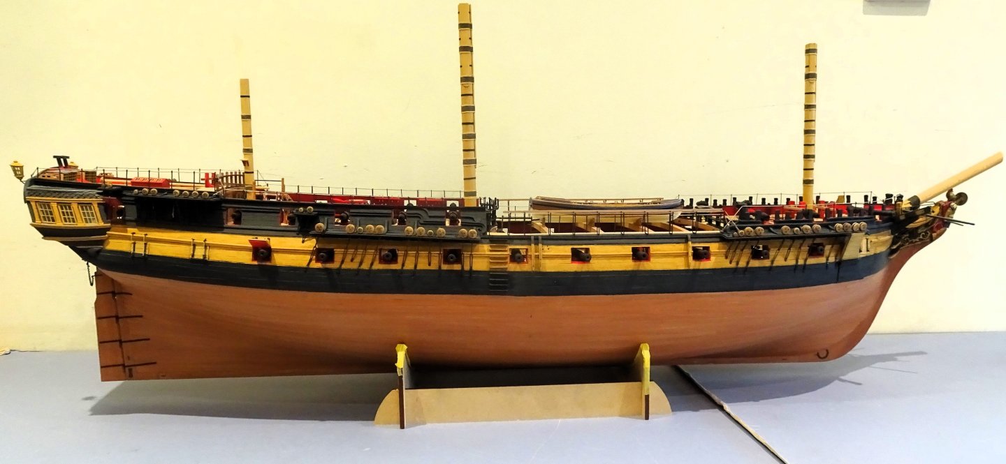
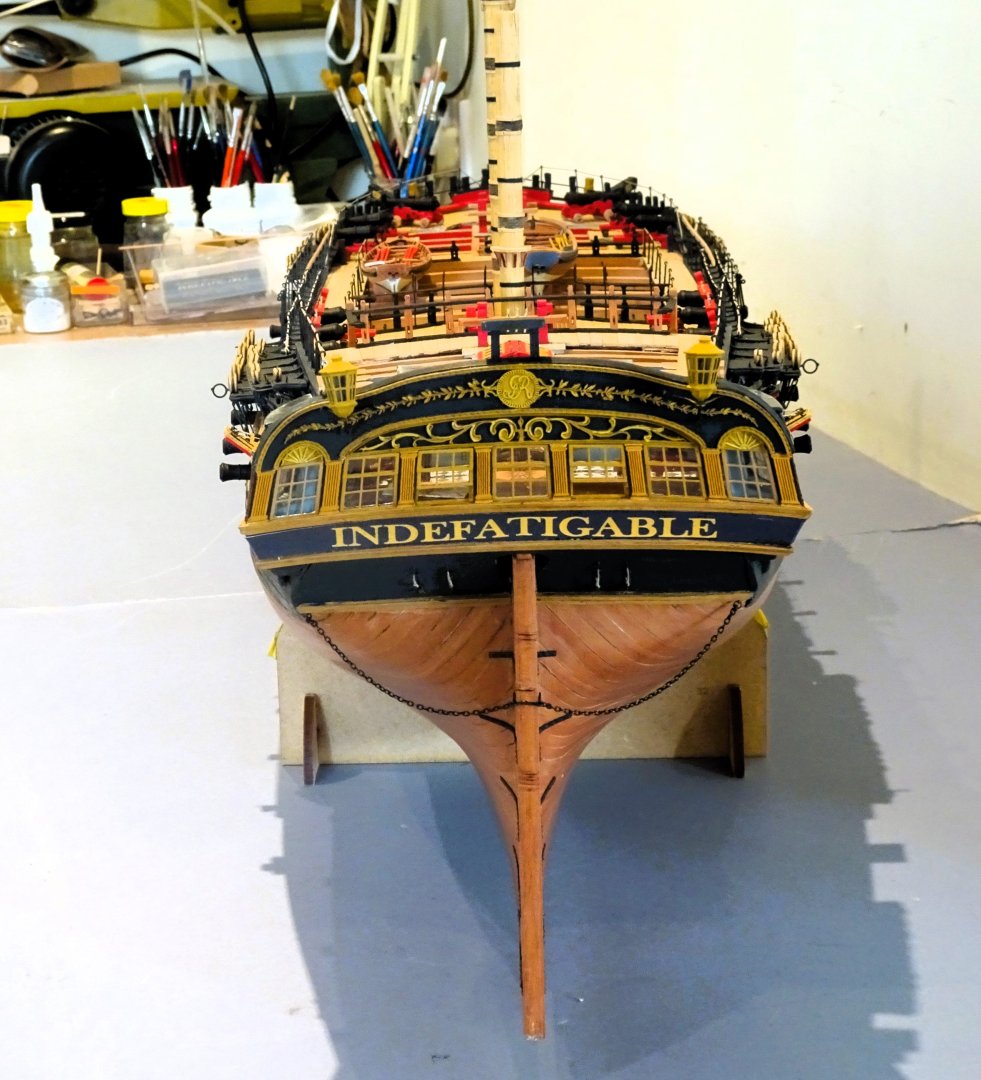
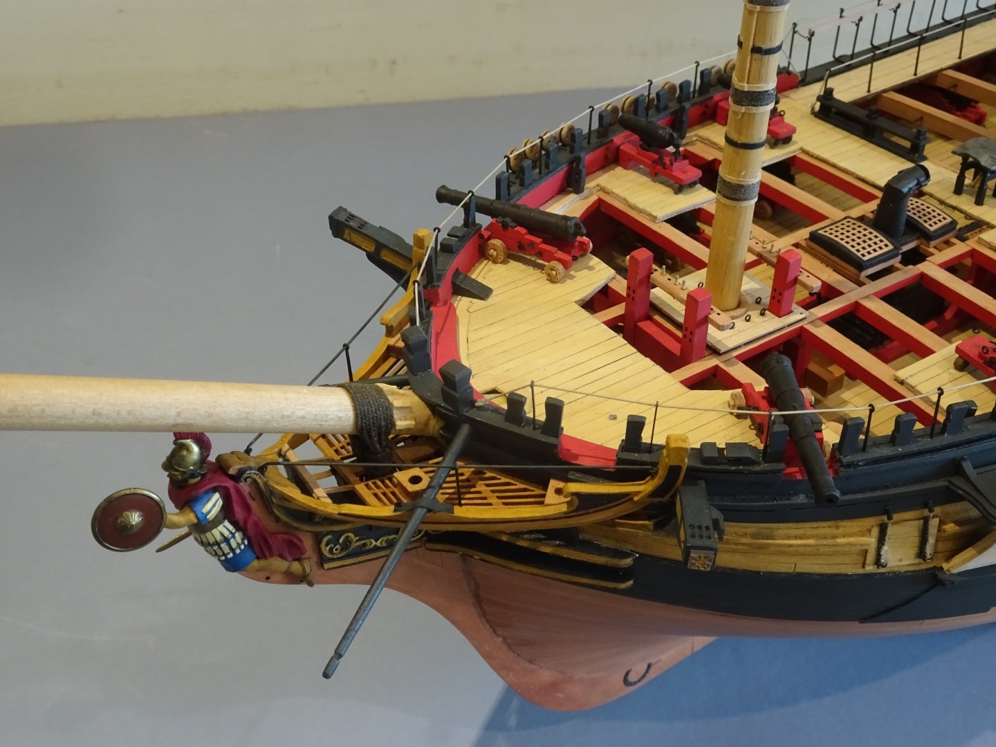
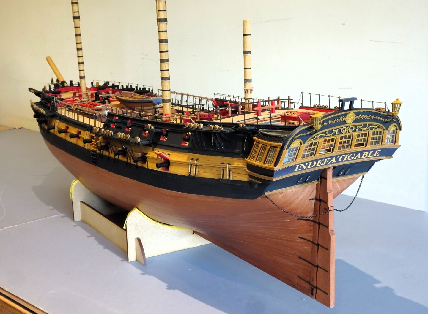
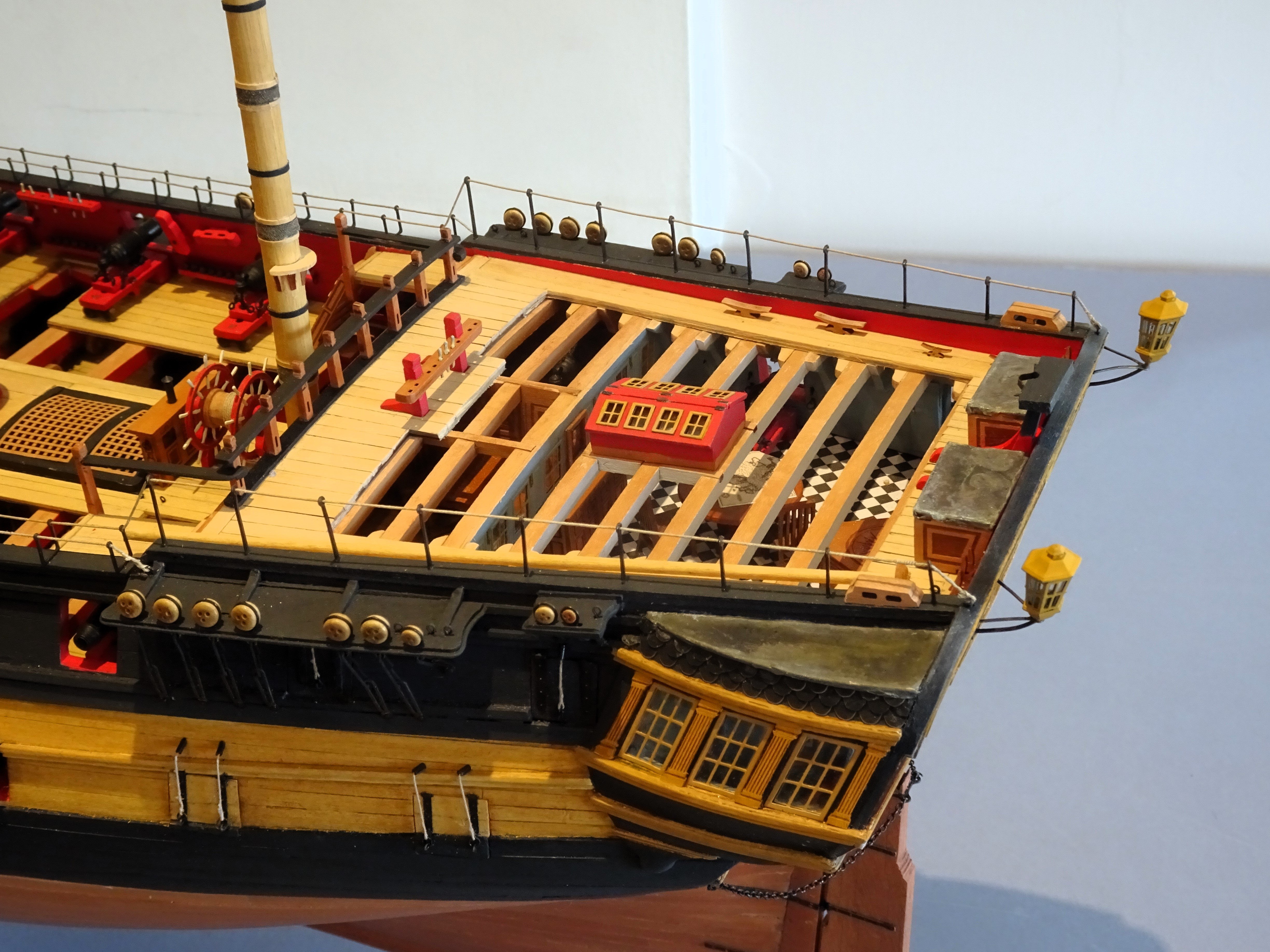
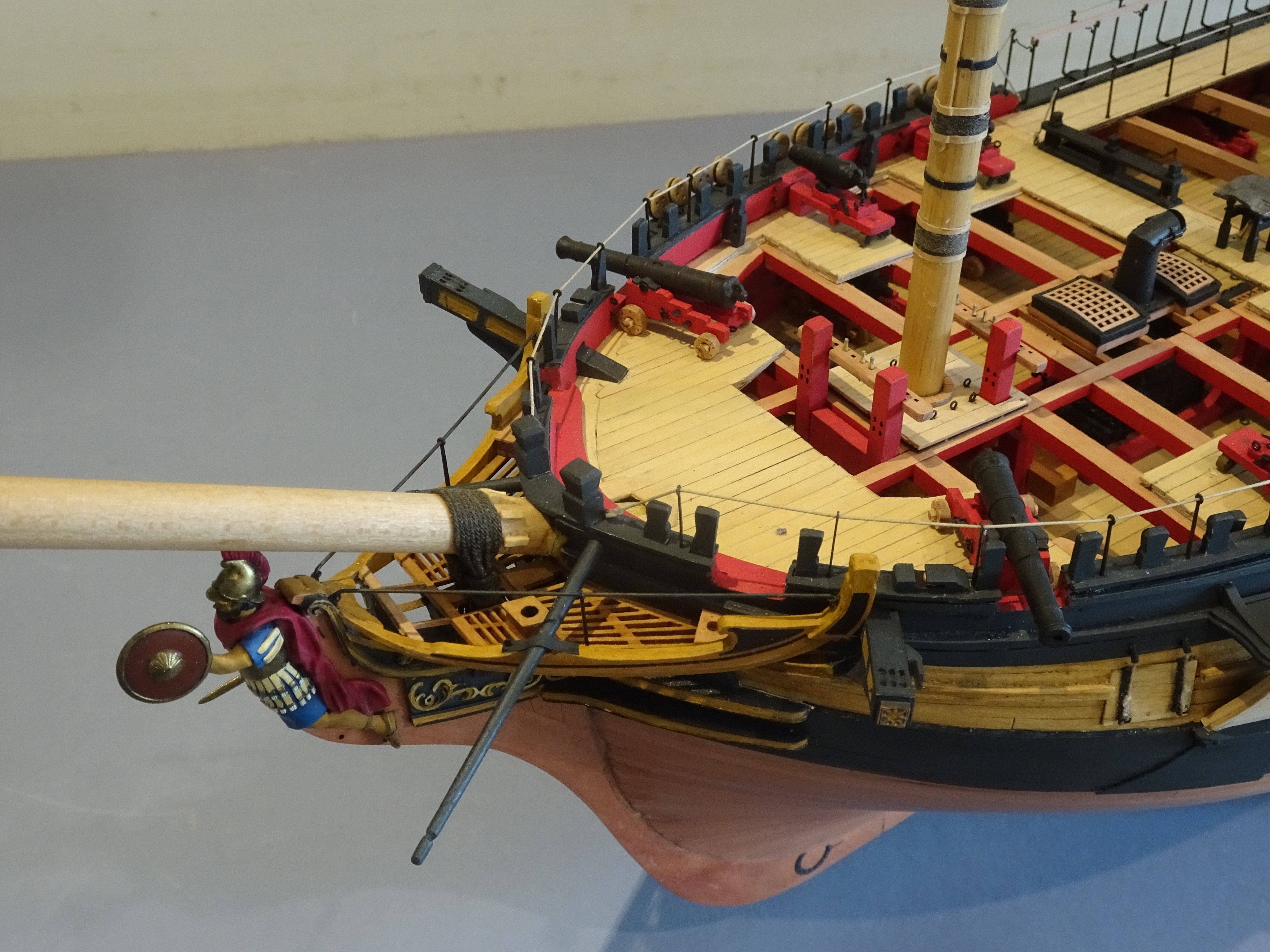
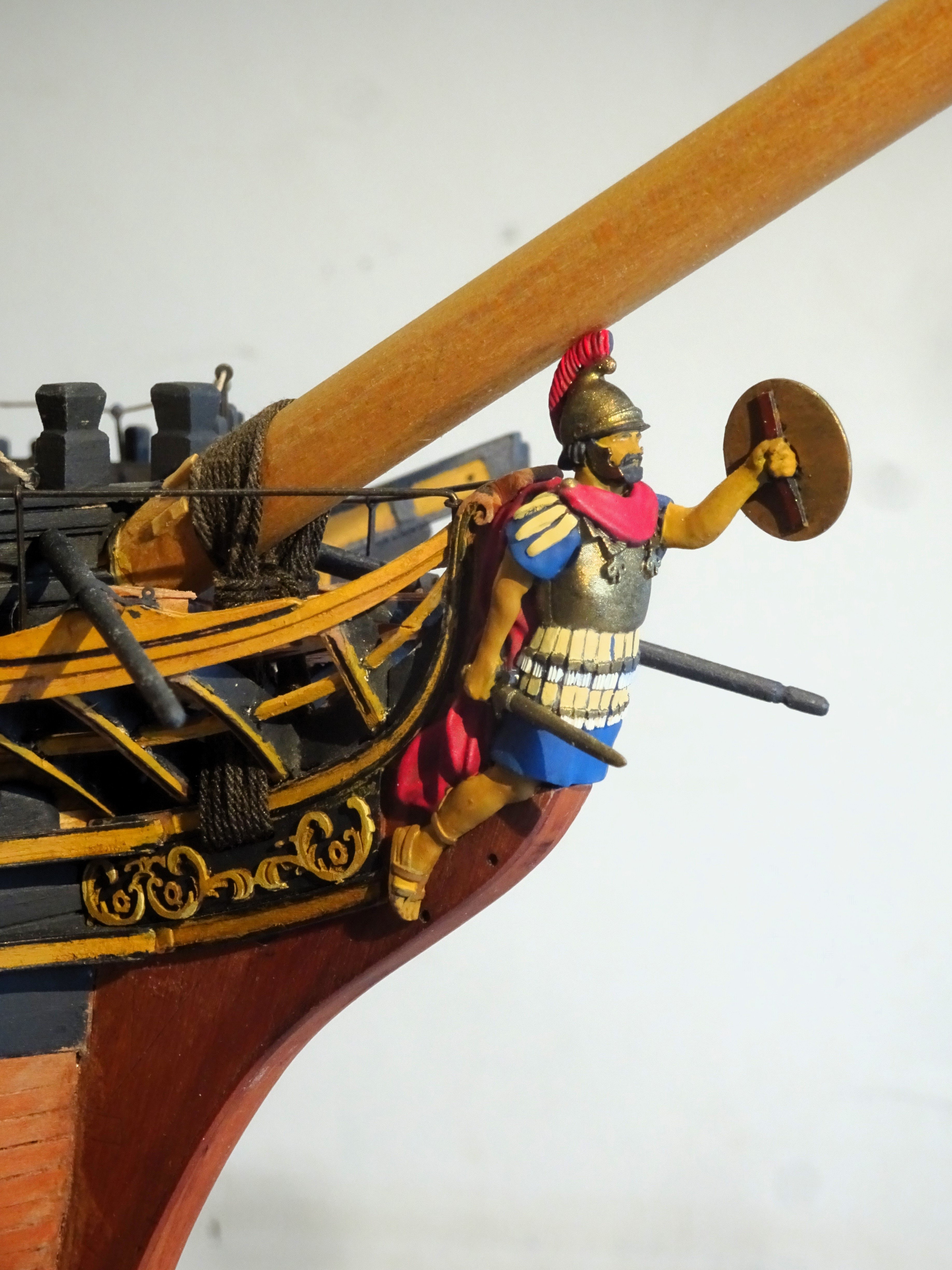
Indefatigable sort of spans this period, all black and yellow, no decorative topsides, but the stern gallery still looks good to my eye. She is modelled with an open Fo’csle before her bulwarks were built up, and she does have a magnificent Figure at her head.
I am more than happy to have both in my collection.
Thank you, Chris, for providing me with an engrossing thirteen months of work. It is a tribute to your designs, to be able to build a model of this quality and detail in such a short time.
Thanks are also due to James, for producing the prototype ‘Indy’ build which provided a very useful reference guide.
B.E.
02/05/2024
-
Thank you guys for your supportive comments and likes throughout this build, hope it will be useful to those following on.
@ Nils – I have a glass case ready; it was cheaper than using acrylic, but the downside is weight.
It is going to be an interesting exercise getting her into display position.🤔
B.E.
- BobG, Ronald-V, Mirabell61 and 1 other
-
4
-
Post One hundred and Seventy-one
Album photo's
I have at last got around to taking the completion photo’s which will form part of the Photo build record book that I’m currently putting together.
4395
 4361A
4361A
4392
4364

4365

4391
4390
4396
4369

4405

4395
2161A

2145a

4397
2162a
2164a

4380

4379
4388
4494a
I am currently faffing around with a clinker built 18’ cutter, and ‘Indy’ is yet to be enclosed in her case, so the story has not quite ended.
Then there’s the 26’ Launch, still on my mind.
Cheers,
B.E.
-
Hi Bug,
I used three each side on the Fore and Main Topmast shrouds, none on the Mizen. I used the aftermost ones for the fore and Main T’gallant yard lifts.
I didn’t use the other two.
Two each on the Fore and Main lower Shrouds, one on the aftermost Mizen shroud (used for the Mizen Topmast yard Lift)
I recall that I used the TFFM Vol IV to decide which lines went where.
TFFM indicates the fore and Main topmast shroud cleats were also used for the t’gallant clues, and the Fore topmast shroud cleats for the Main T’gallant Bowlines.
I belayed a lot of lines to the rails as indicated in the TFFM.
There are no belaying pins on my Pegasus.
Nice work on those shroud cleats.👍
B.E.


26 ft Launch 1795 by Blue Ensign - Vanguard Resin/wood small boat Model 1:64 scale
in - Kit build logs for subjects built from 1751 - 1800
Posted
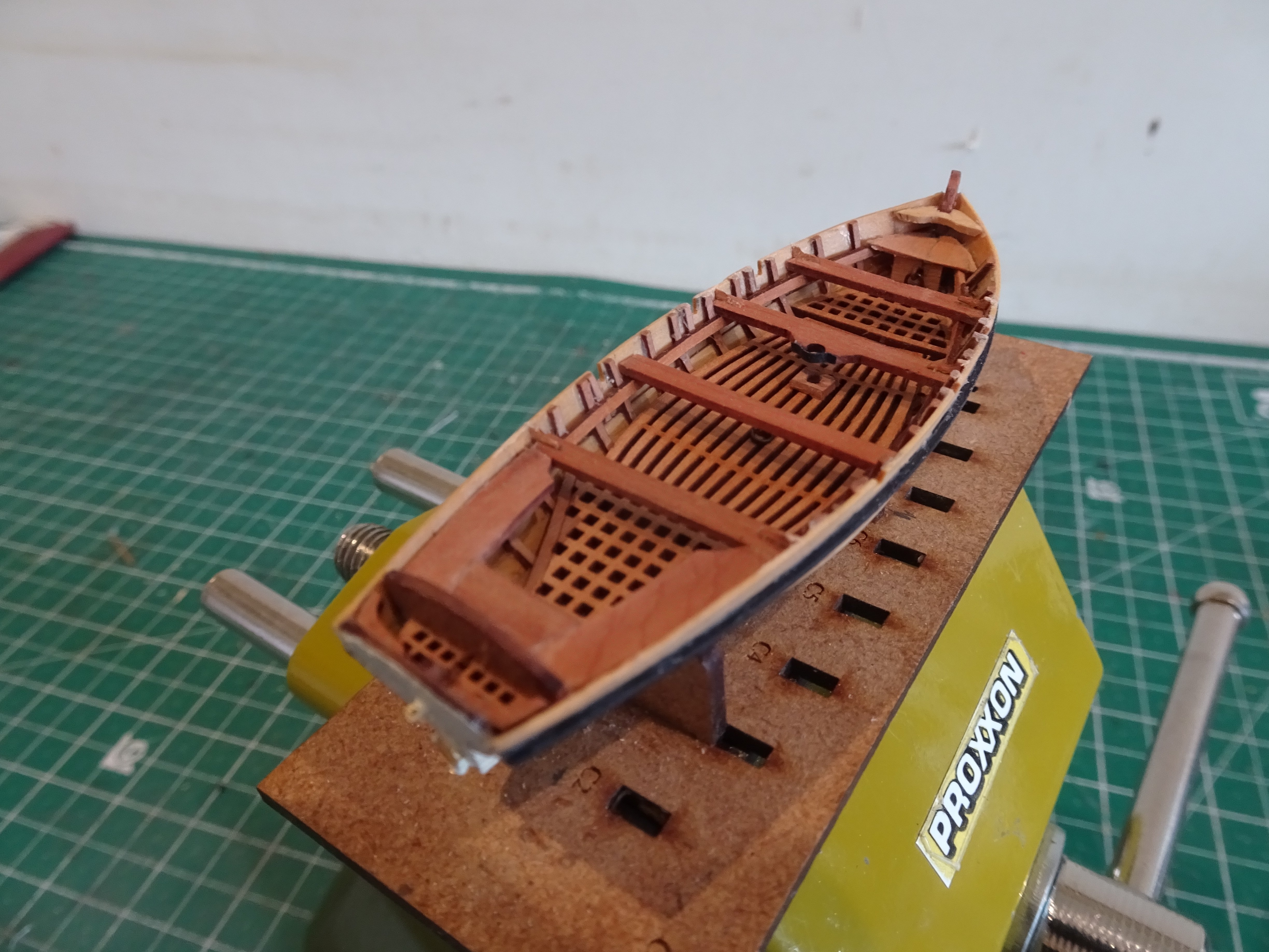
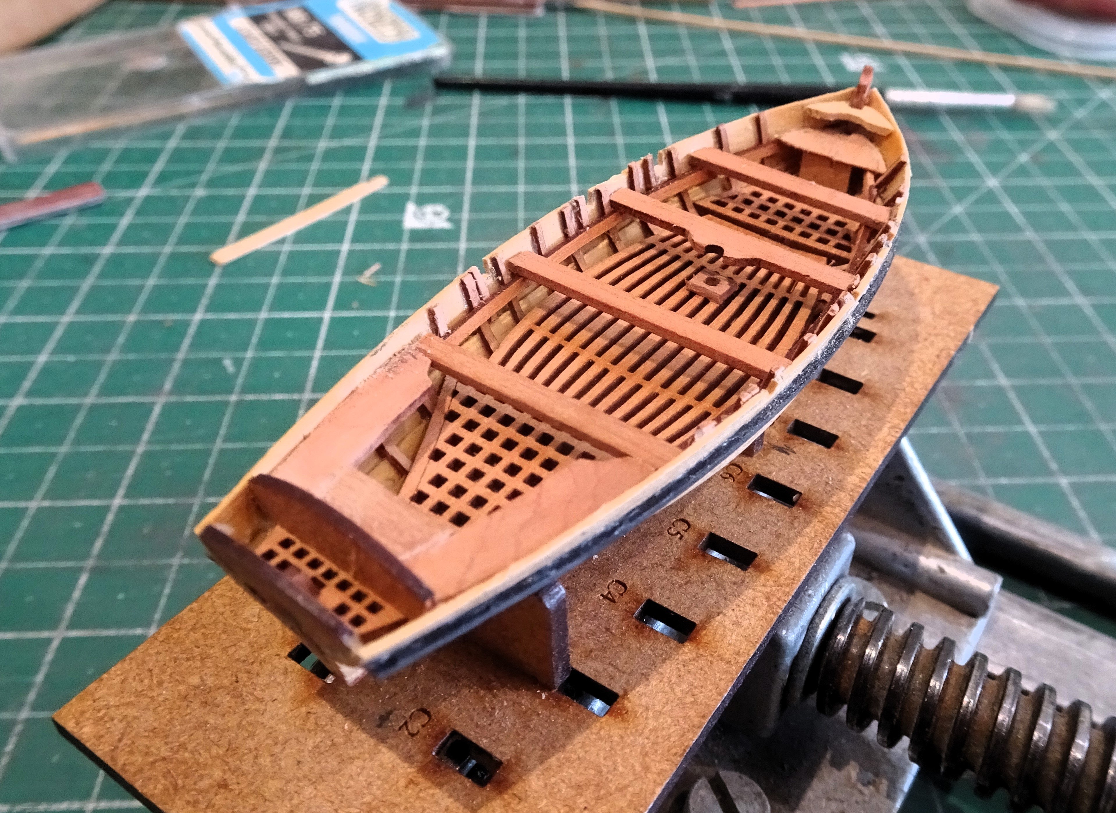
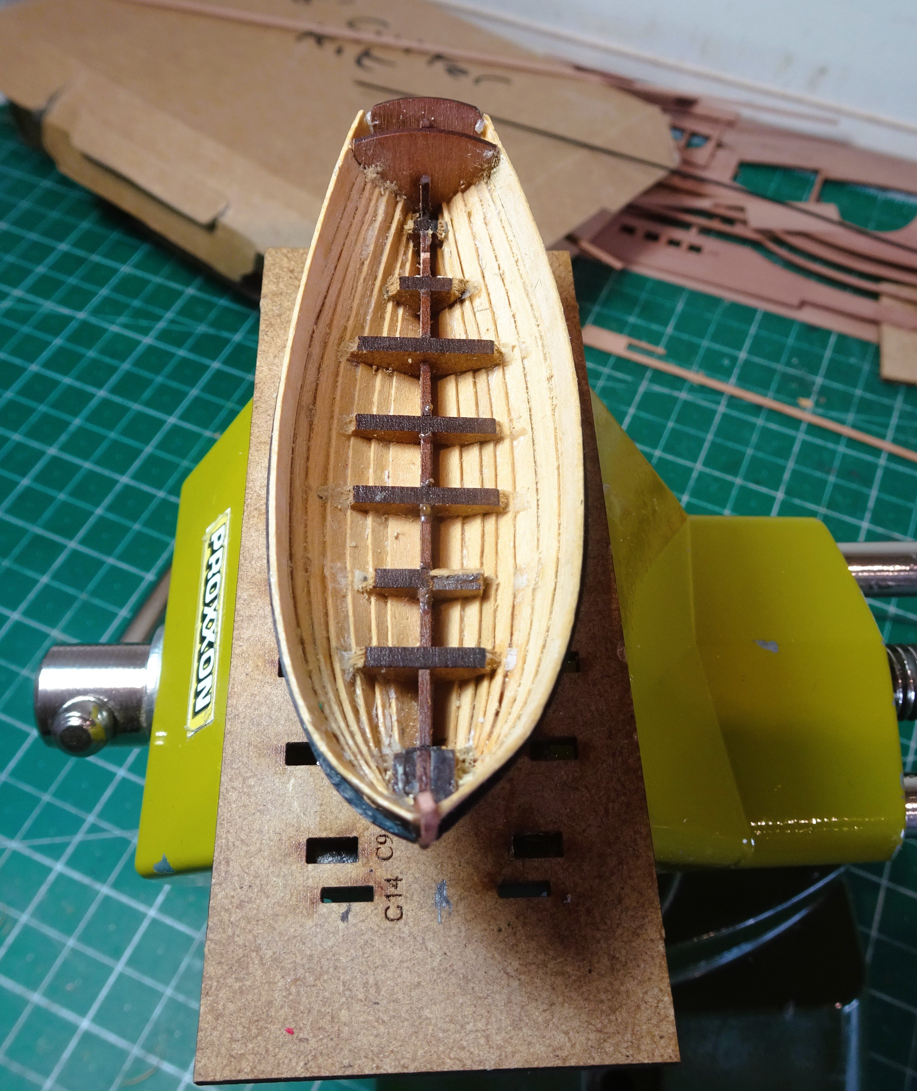
Post 3
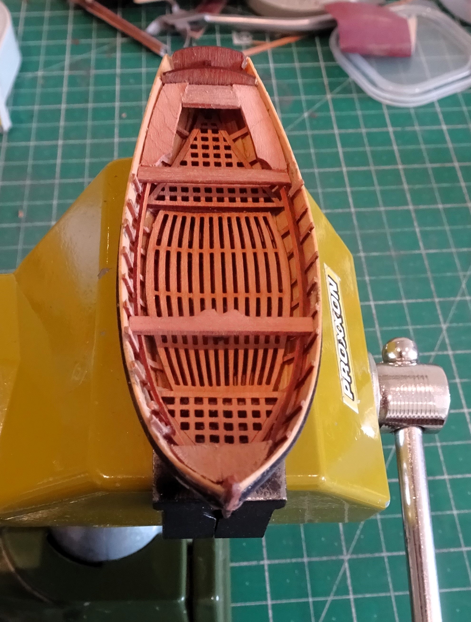
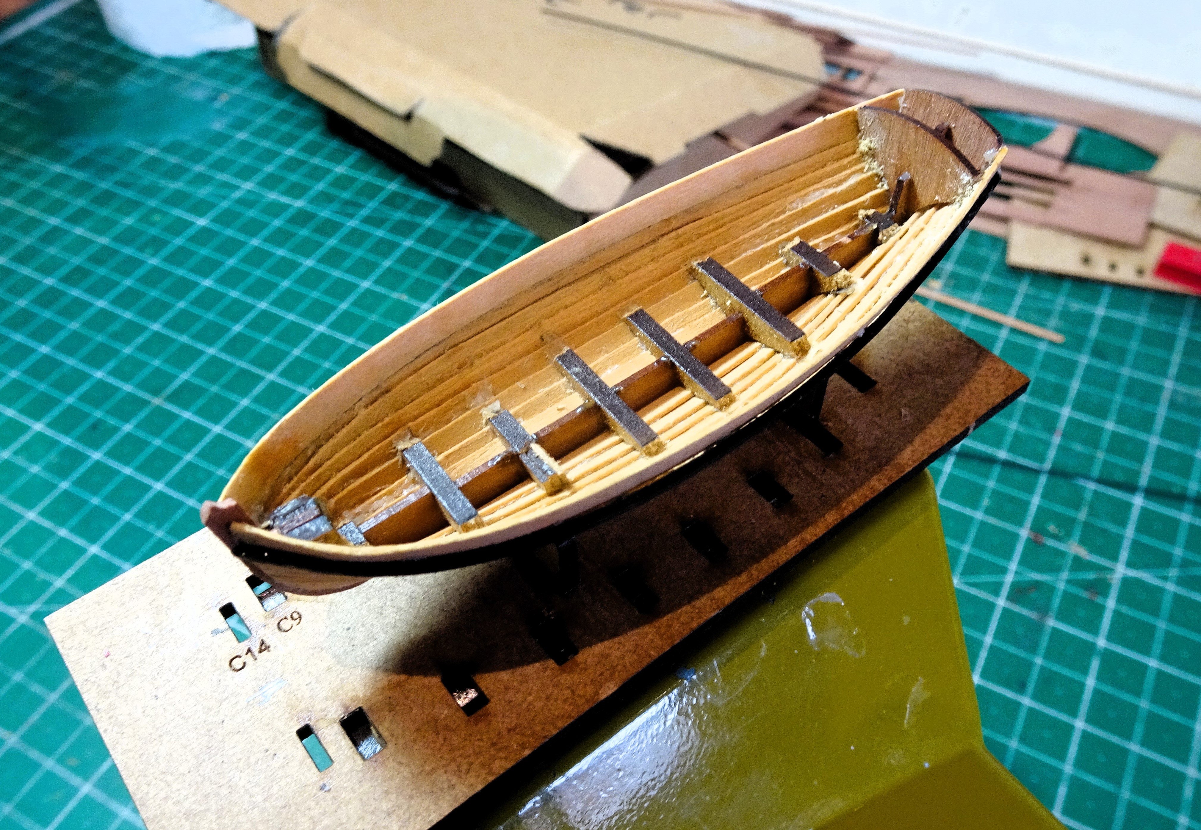
Internal fittings
All the wooden internal fittings are laser cut on 0.8mm Pear sheet.
4788
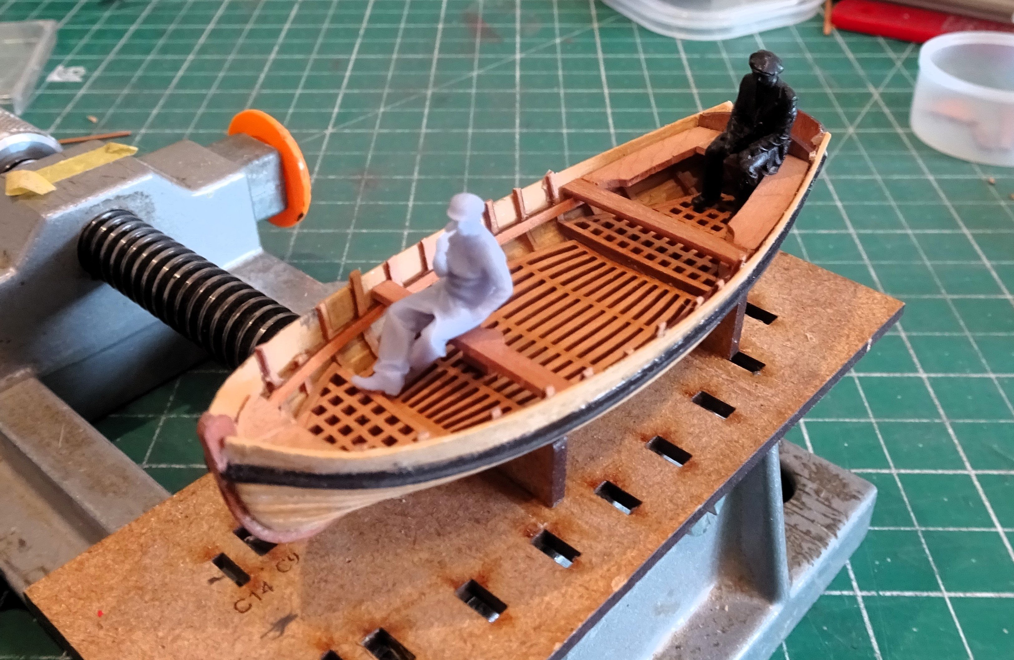
The thwarts fit perfectly in their allotted positions, and at a correct rowing height.
4797
4799
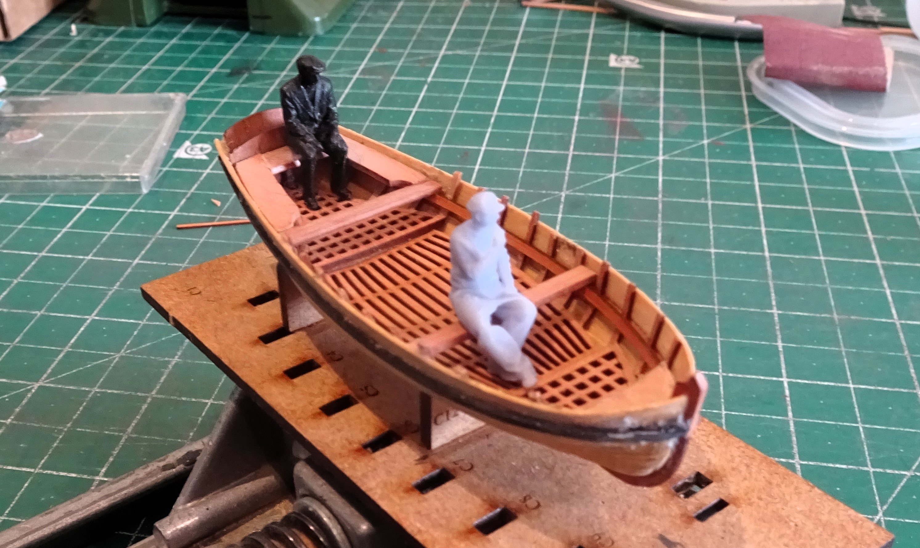
Always good when the feet of a scale figure are a perfect fit for thwart and footwaling.
The stern benches are notched to fit over the frames, and again are a perfect fit.
4796
One feature that caught my eye was to see that the benches fitted over the aftermost thwarts.
The drawing would support that view, at least on this design of Launch.
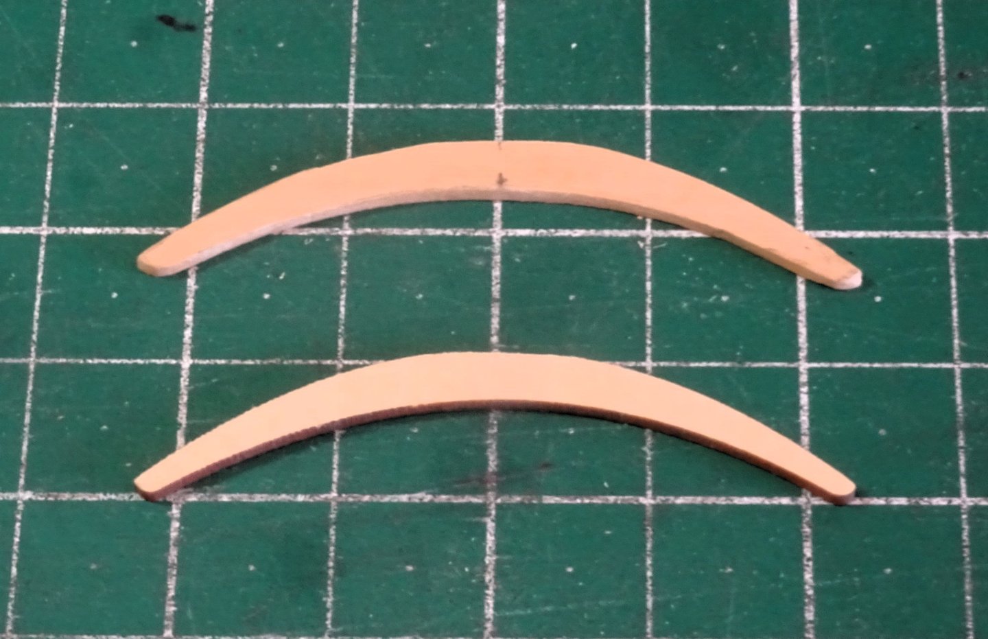
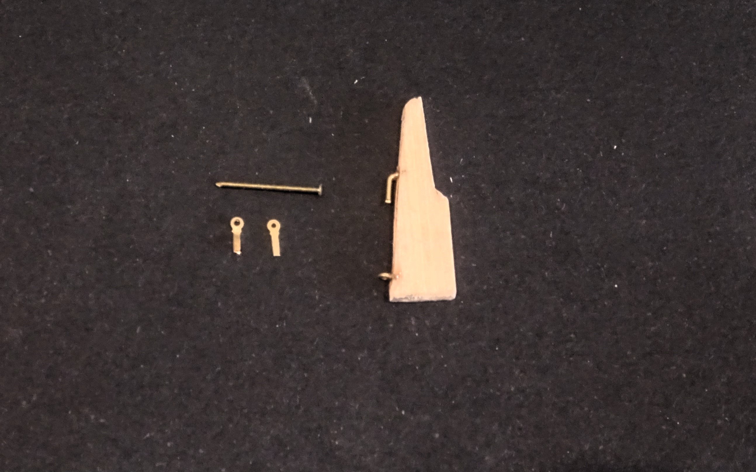
The Rudder
This is fairly fragile at 0.8mm, and the head of the rudder split a little in the area of the tiller insert.
The kit set-up has the addition of side cheeks, for want of a better word, either side of the head, between which the tiller is inserted.
I don’t recall ever seeing such an arrangement on boat rudders. I wonder if it is supposed to represent a sort of tiller cowl that slots over the rudder head?
4804
I don’t know if such an arrangement ever existed in the 18thc, but either way I thought it looked a little odd, and rather ugly, so I re-made a new rudder using 1mm Pear. (left hand version)
Oars are supplied in 0.8mm Pear and I note that Chris has designed in the broader elements of the loom. The blades are also finer than on other editions.👍
4807
I think the oars more than fulfil their purpose at this scale.
The next post will see the completion of this long weekend project.
B.E.
25/05/2024