
.JPG.ca33079f5815b861e67b9c2cccd37982.JPG)

Blue Ensign
-
Posts
4,333 -
Joined
-
Last visited
Content Type
Profiles
Forums
Gallery
Events
Posts posted by Blue Ensign
-
-
Thankyou Kevin, Bug, and Rusty, your words are much appreciated.
@ Bug - That Chris Watton has a lot to answer for, I dread seeing the next irresistible model to emerge from The Forest of Dean, I’m already struggling to find a suitable space for ‘Indy’
Cheers,
B.E.
-
Thank you Jason, enjoy your Pinnace, it's a great little kit.
Post One Hundred and Sixty-one.
Building the 32’ Pinnace (Part four)
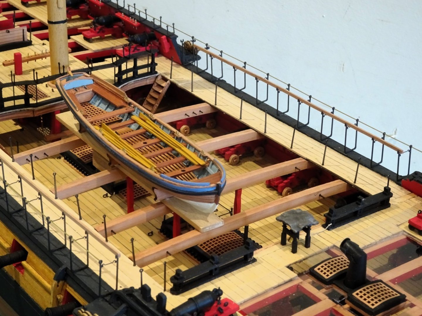
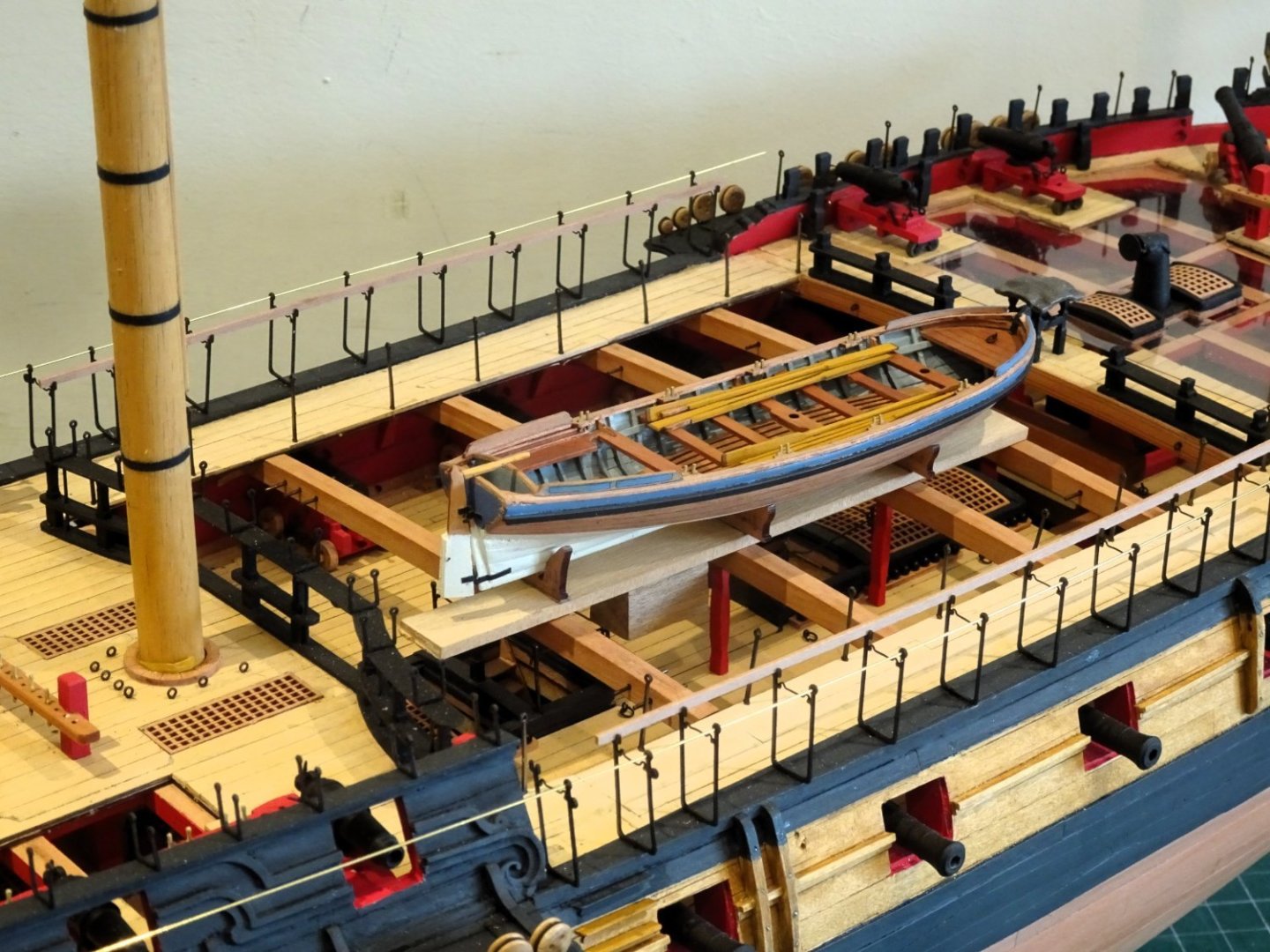
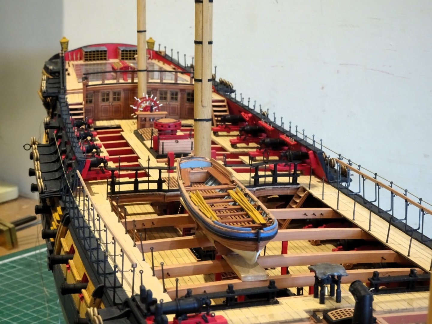
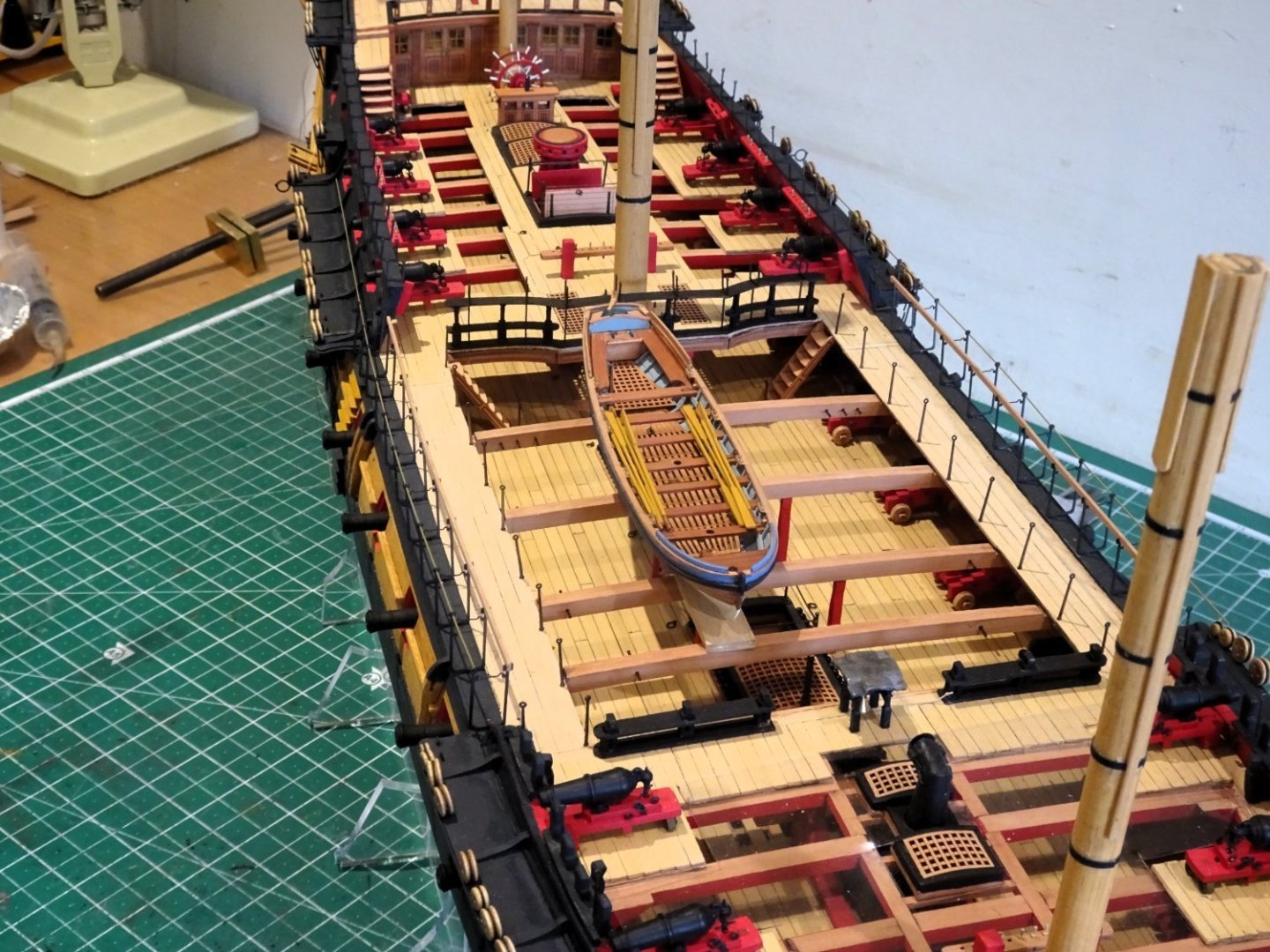
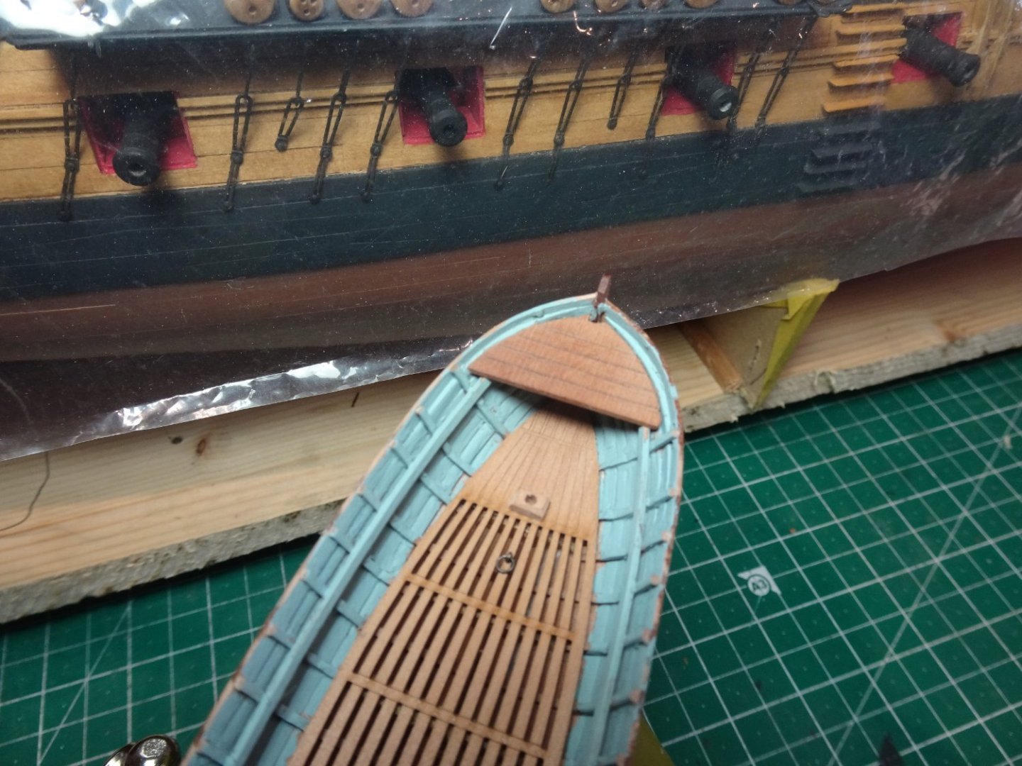
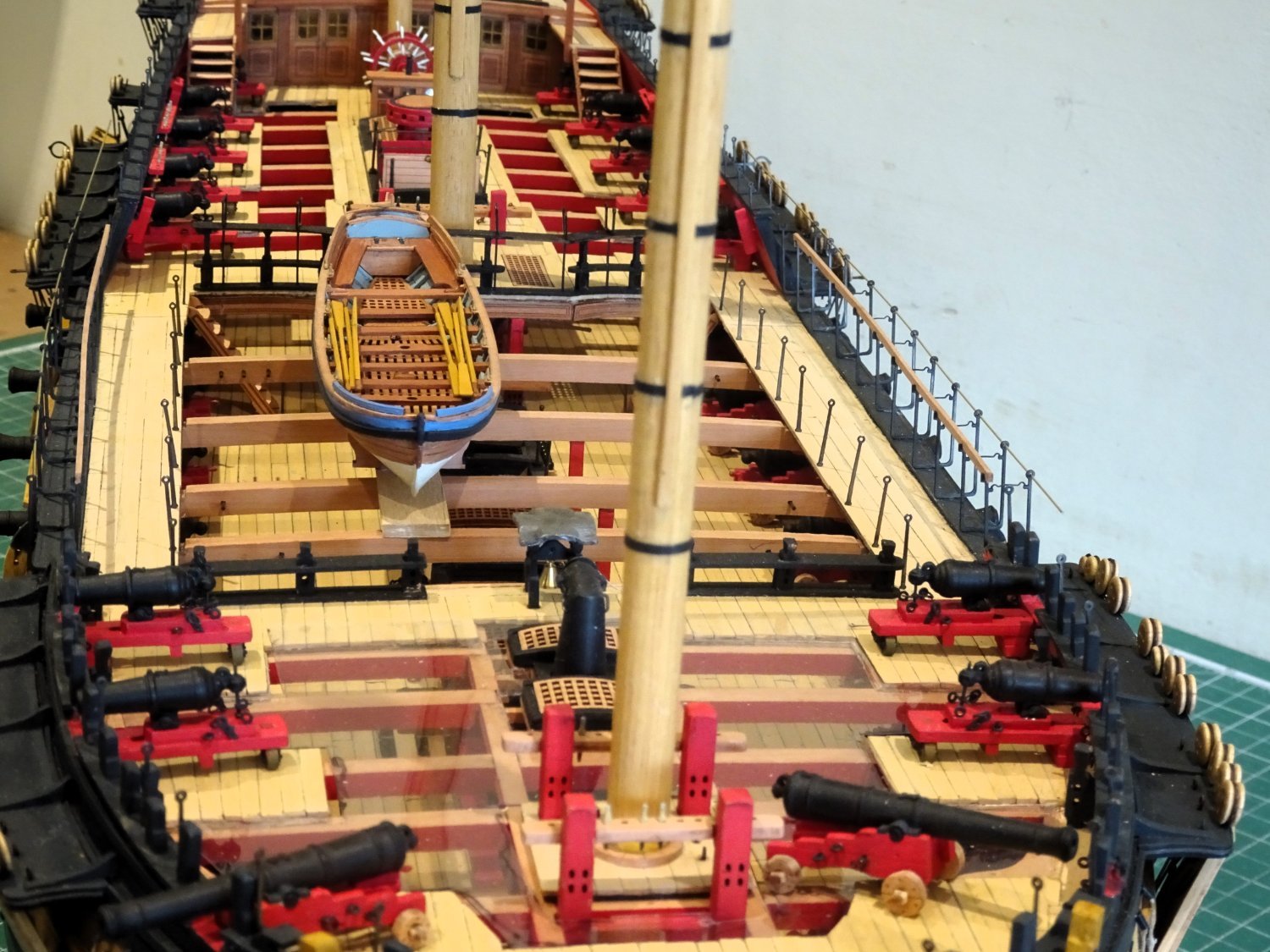
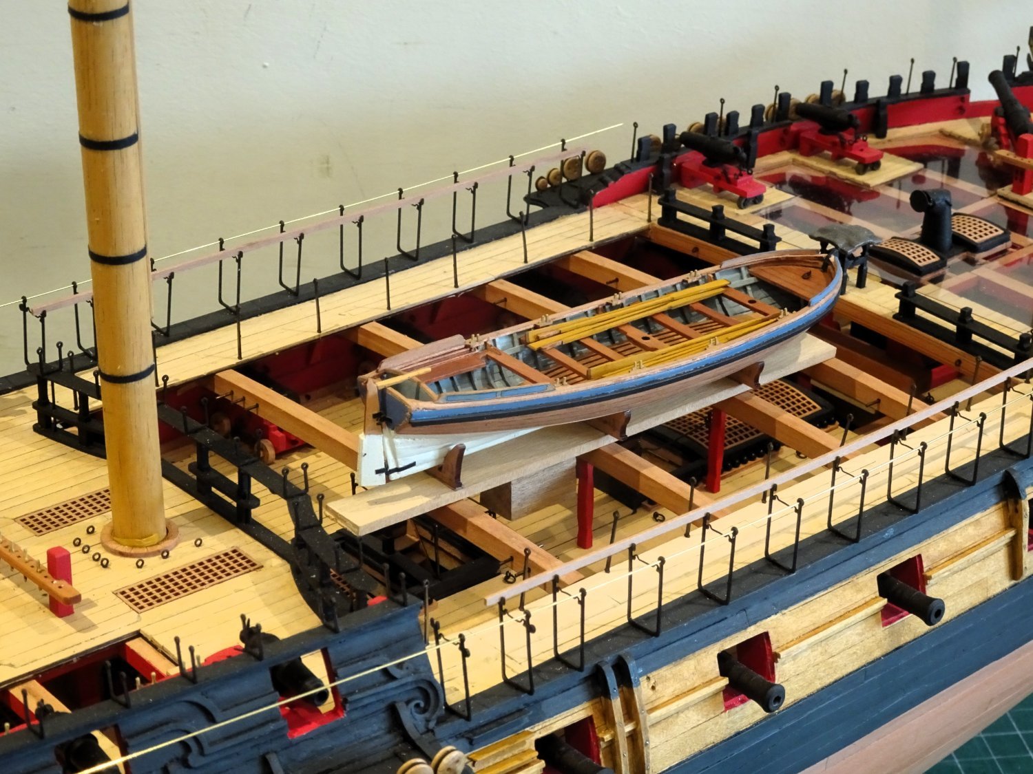
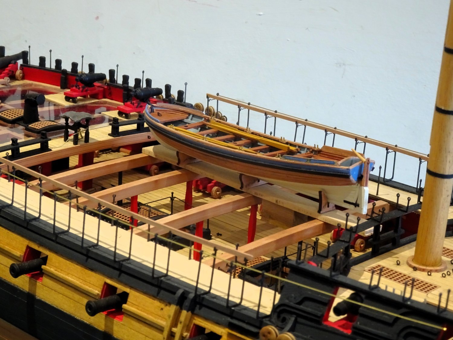
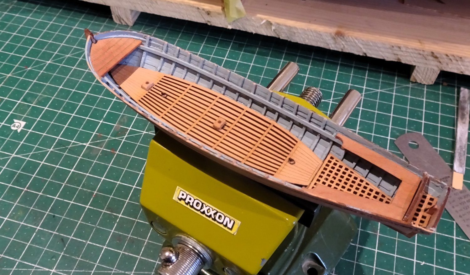
At this point I couldn’t resist the urge to see how the Pinnace would look onboard ‘Indy’.

4108
4112
Temporarily placed in the suggested position on the skid beams.
4113

4117
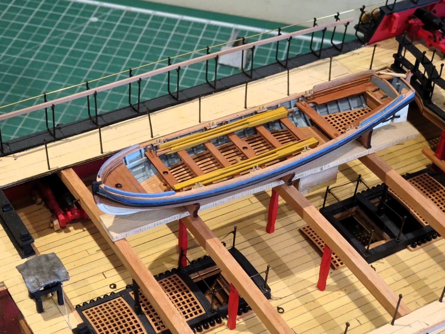
The kit provides a set of oars in laser cut Pear.
These benefit from a little fettlin’ beyond char removal.
The blades should be thinned down toward the outer end, and the shank rounded a little at the bottom third leaving the upper two thirds square to represent the loom.

4121
4123
4127
4128

4106
4109
I think a spot of woolding is up next.
B.E.
26/03/2024
-
Post One Hundred and Sixty.
Building the 32’ Pinnace (Part Three)
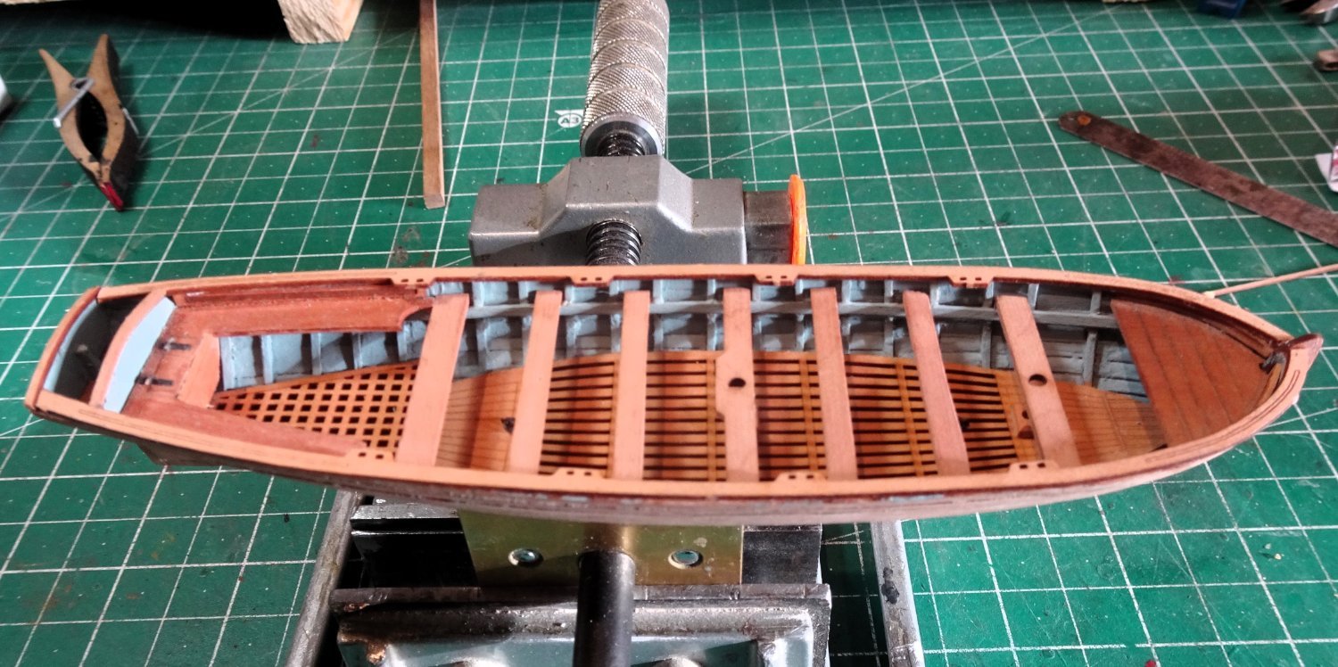
Getting the correct thwart levels and height is a critical part of assembly.
It is important to get the thwarts all square across the boat.

4038
When fitting the thwarts it is advisable not to exert even light pressure on the centres of the thwarts, particularly those with the mast holes in them.
The final tricky part is fitting the gunwales.
These delicate parts are pre-cut and include the thole pin fittings.
 4041
4041
I decided to fit the gunwales as provided, complete with thole pin fittings for eight double banked rowing stations.
I know all the arguments about Pinnaces being single banked to accord with historical custom and practice, and that boats of 32’ were 10 oared, and even that traditionally Pinnaces had a centre board running between the thwarts.
There are more than a few difficulties involved in making a diversion from the kit to reflect the above, and as with the smaller Pinnace on Sphinx, after long consideration I decided that leaving well alone was the best course.

4044
No matter, it is a very fine boat to display with Indy.
Chris has put a lot of thought into the design of these boats, and the fine detail is the best around at this scale.

4055
The wale is next fitted and does require a degree of edge bending to conform to the line as it rounds the bow.

4048
4045
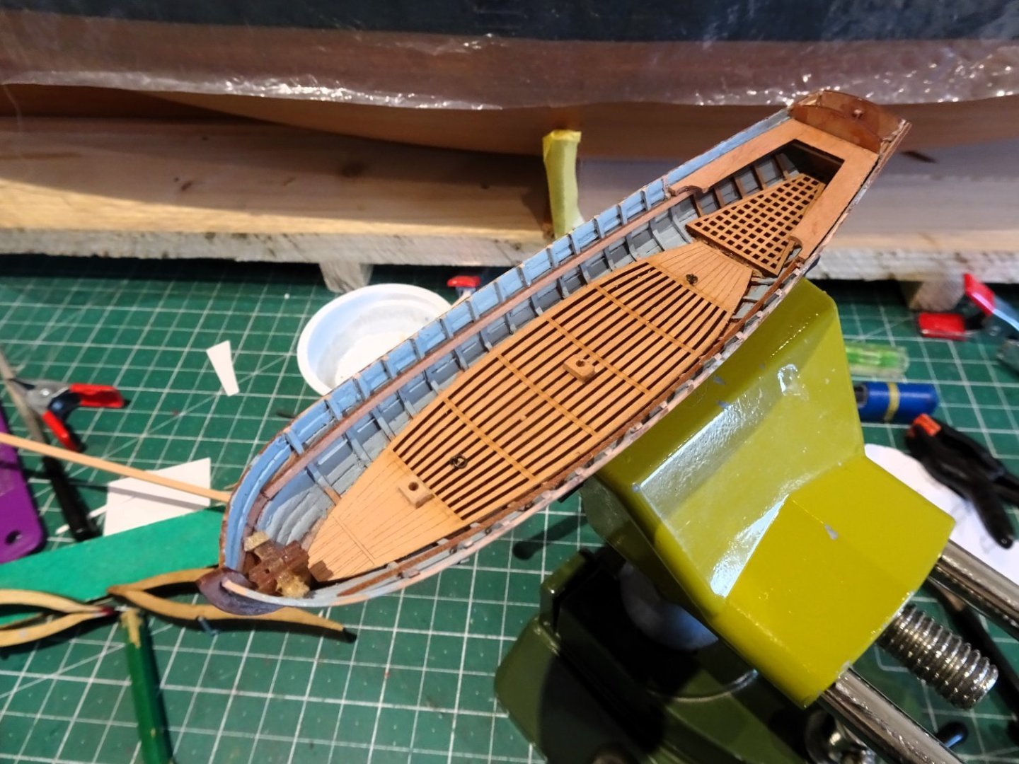
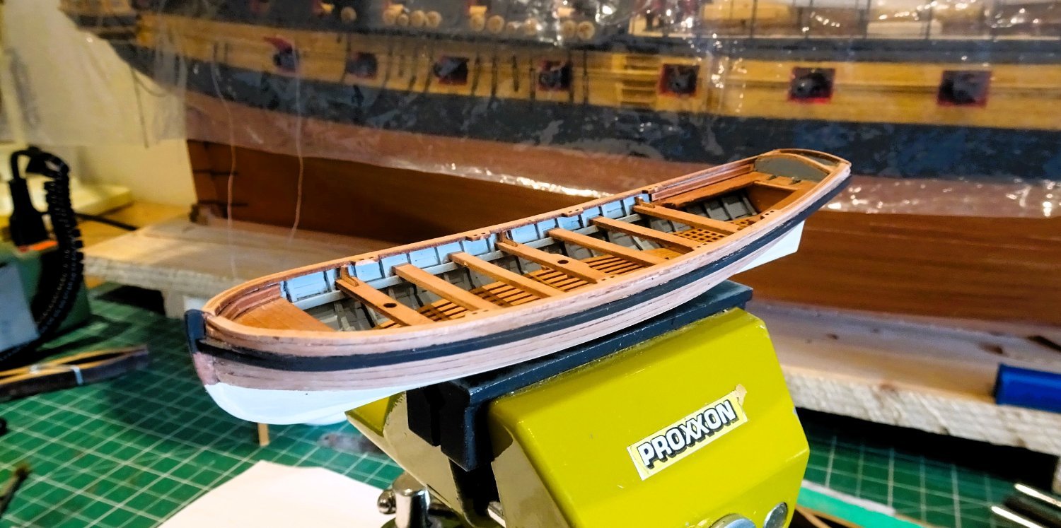
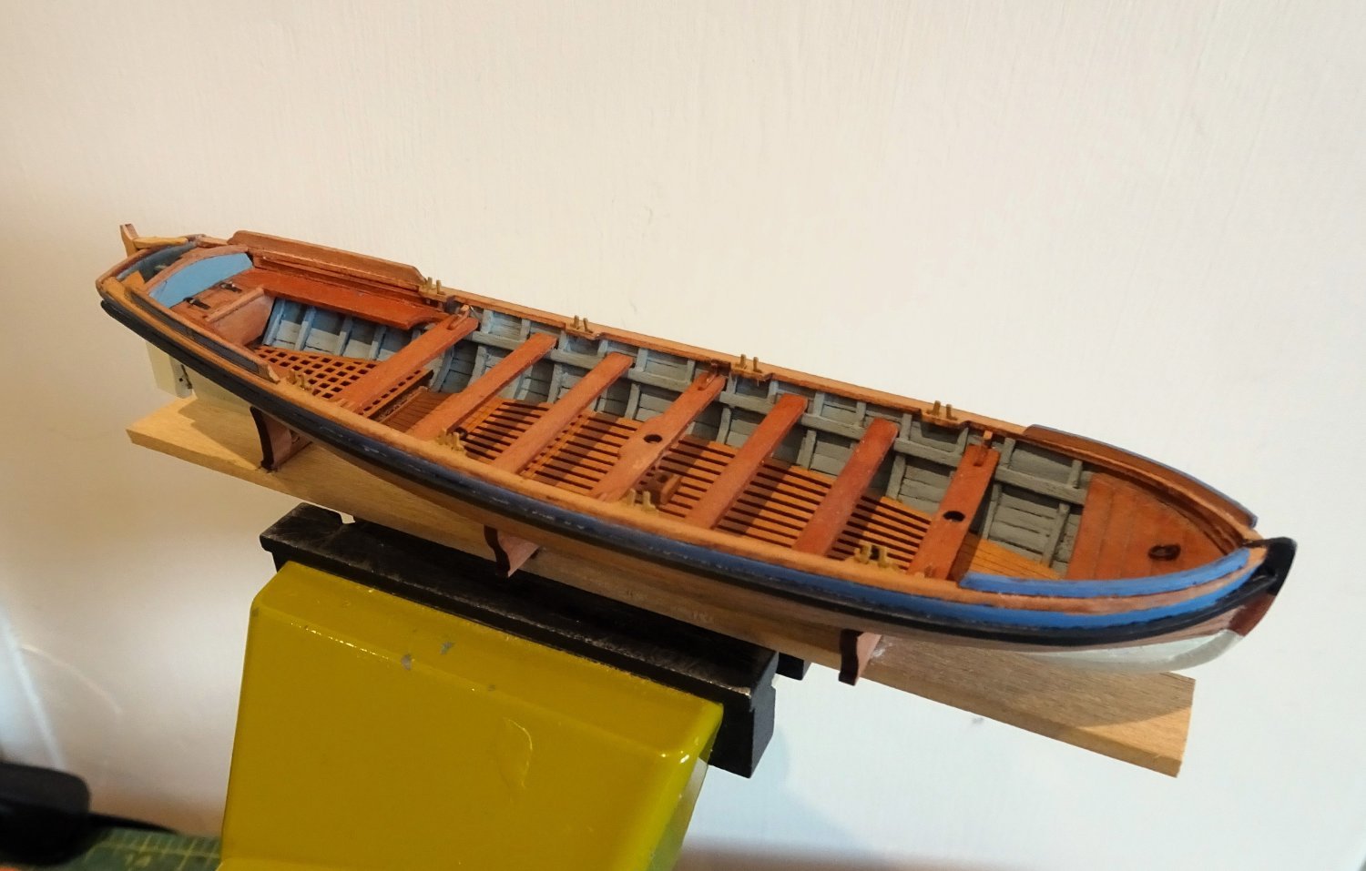
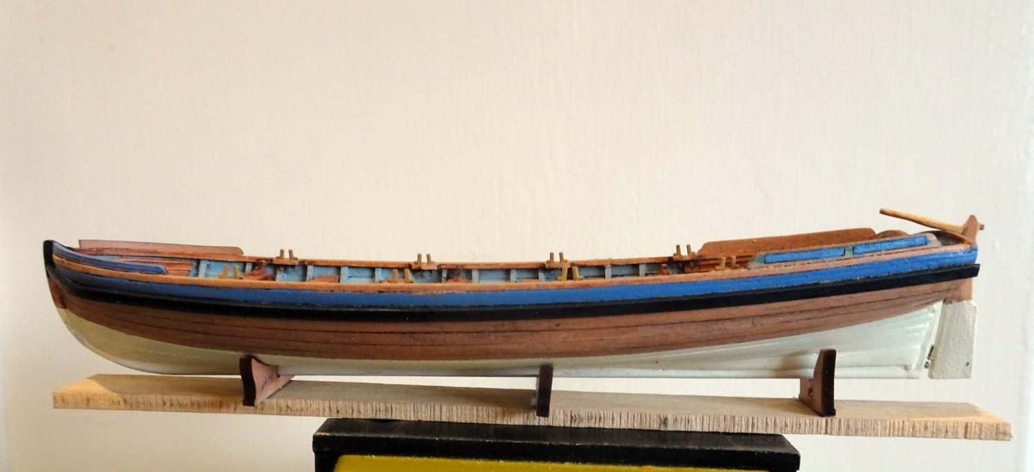
The lower hull has been painted in Ivory to provide a contrast with the ‘bright’ timbers up to the wale.
Painting these small boats requires careful masking but the tyranny of the macro w-i-p photos required several goes to improve the lines to a point I found acceptable.

4103
Vallejo blue/grey is used to decorate the top strake and transom, and w-o-p is applied to the bare wood.
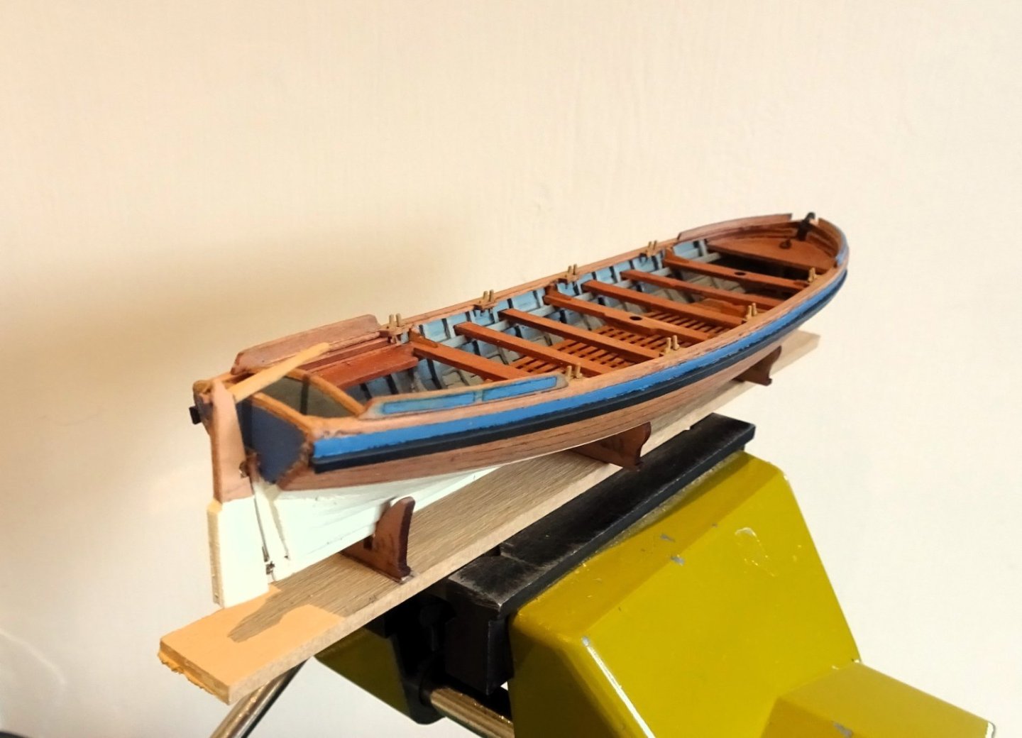
4104
The rudder is fitted with the modified quick release arrangement common on these boats.

4097
Making these small boats provides hours of fun and frustration in equal measure. They are absorbing little projects that I enjoy doing despite the frustrations at times.
Just the finishing touches to add now.
B.E.
25/03/2024
-
Fabulous set of photo's Daniel, this is one classy build, that holds little fear of the macro lens.
B.E.
- Thukydides, Moonbug, Glen McGuire and 1 other
-
 3
3
-
 1
1
-
Thank you Giulio, apart from the Capt. included on the Quarterdeck of the finished model, the others were assembled from various bits of body parts from various sources, completed with modelling clay. The Capt. is a Mantua white metal figure.
Some of the figures are too rough to include on a finished model but they serve as scale markers.
B.E.
-
Thanks Nils,
I've built six of these boats without any problems when removing the frames, but with this one the planking separated in sections, no doubt due to deficiencies in my gluing.
All sorted now.
B.E.
- Mirabell61, CiscoH, allanyed and 6 others
-
9
-
As you say Allan it is a kit limitation; the keelson, such as it is, sits below the footwaling. Modification would entail messing with the provided part - a step too far given that little of it will be seen once the thwarts are in place.
B.E.
- Theodosius, Moonbug, CODY and 2 others
-
5
-
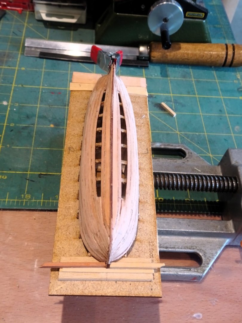
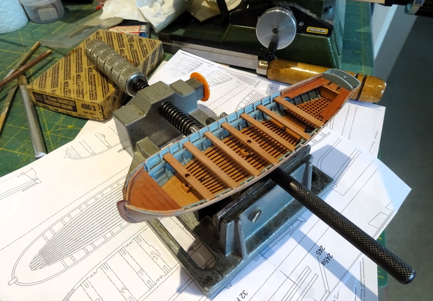
Post One Hundred and Fifty- nine.
Building the 32’ Pinnace (Part Two)
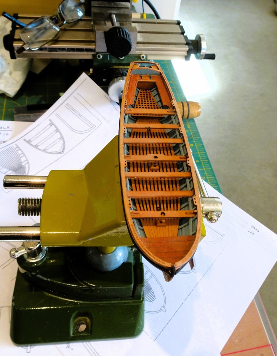
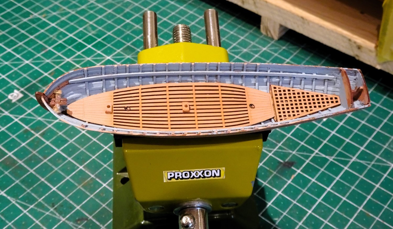
Freed from its building frame and the centres removed the process of fitting out can begin.
I have always been amazed that twisting away the mdf centres leaves the hull intact with little trace of their removal….
But not this time; - the planking partly disassembled, requiring careful re-fitting and use of diluted pva on the inside to stabilise the hull.
How this will impact on the build remains to be seen, but it may be necessary to paint the inner bulwarks.
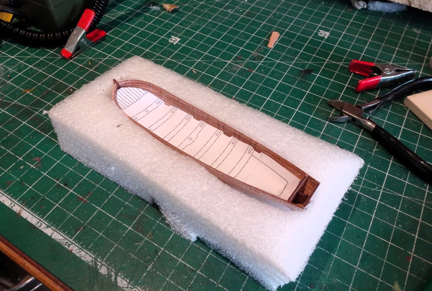
4008
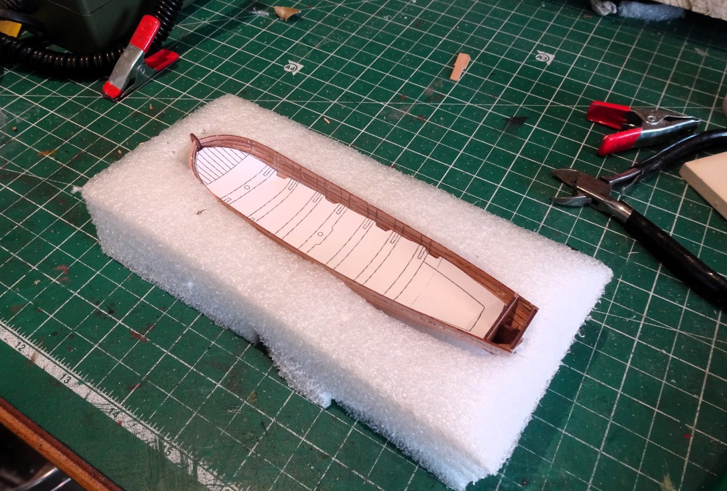
I made a Styrene foam cradle to support the hull whilst attempting to clean up the inside.
I used a combination of micro chisels, pen sander, and sheets to remove the glue adhesions and rough surfaces.
This is quite a fraught operation and needed careful handling.
I take notice of where areas will be covered by the footwaling, fore deck, benches and thwarts, and make pragmatic decisions how far to take the cleaning up in these areas, against risk of further damage.
4007
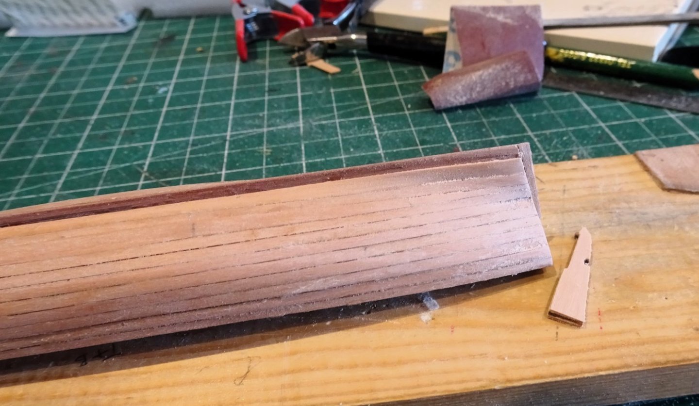
I wasn’t too keen on the set-up at the stern, so I installed a stern post.
I dislike the brass etched rudder facings, supplied with these kits, convenient as they may be. The wooden rudder core was faced with 0.6mm pear and then sanded down to shape.
The hanging arrangement will be modified to reflect the true set-up.

4020
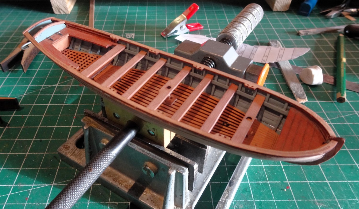
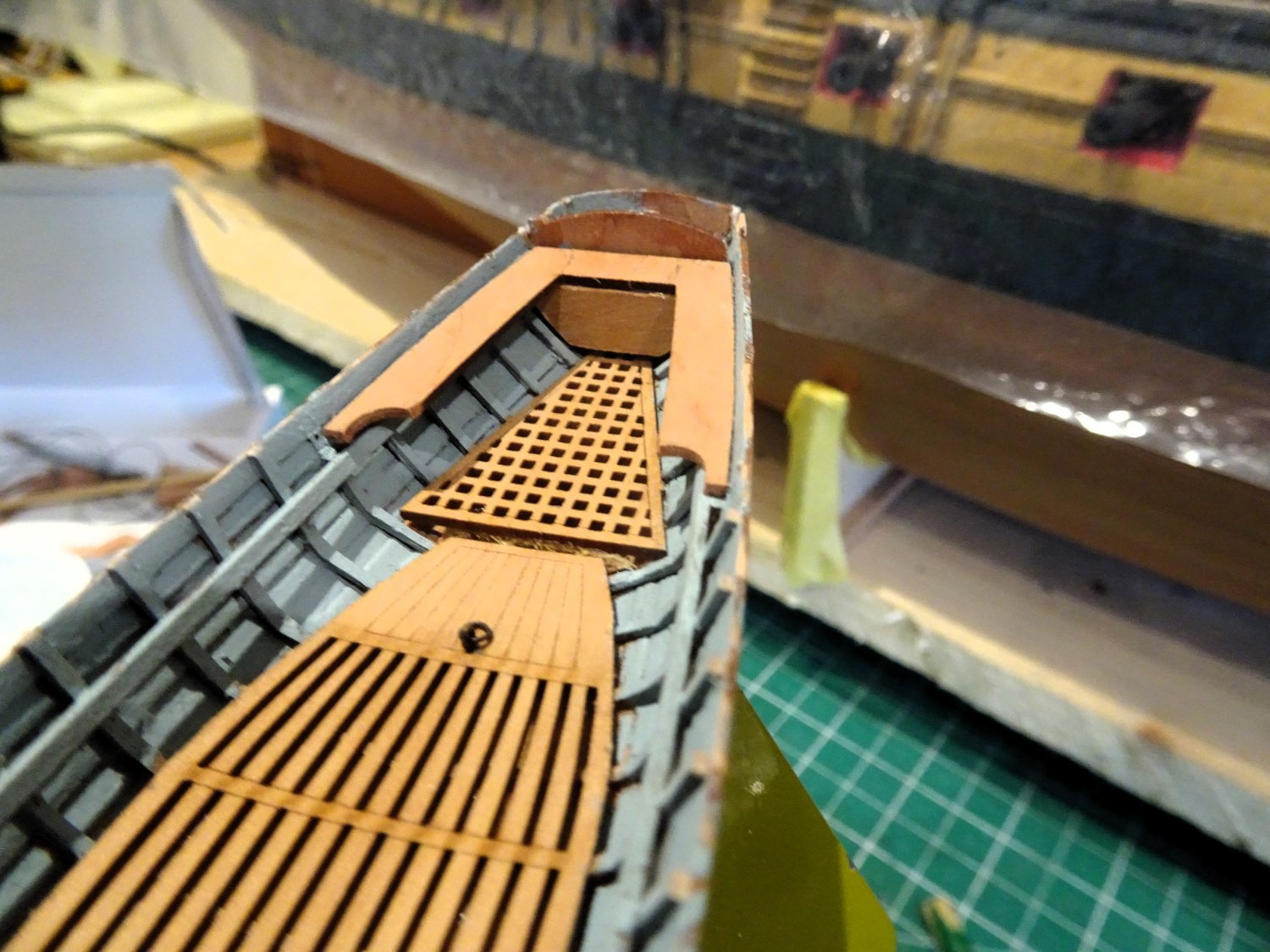
Unlike my previous experience of Vanguard boats the Pinnace has Pearwood gratings and footwaling which I like. More convenient and natural looking than the brass etched versions which require painting and sticking with ca.
At this stage there are a few additions one can make to the boats to add realism.
Lifting ringbolts to the footwaling, and mast steps as shown in the above photo.
4016
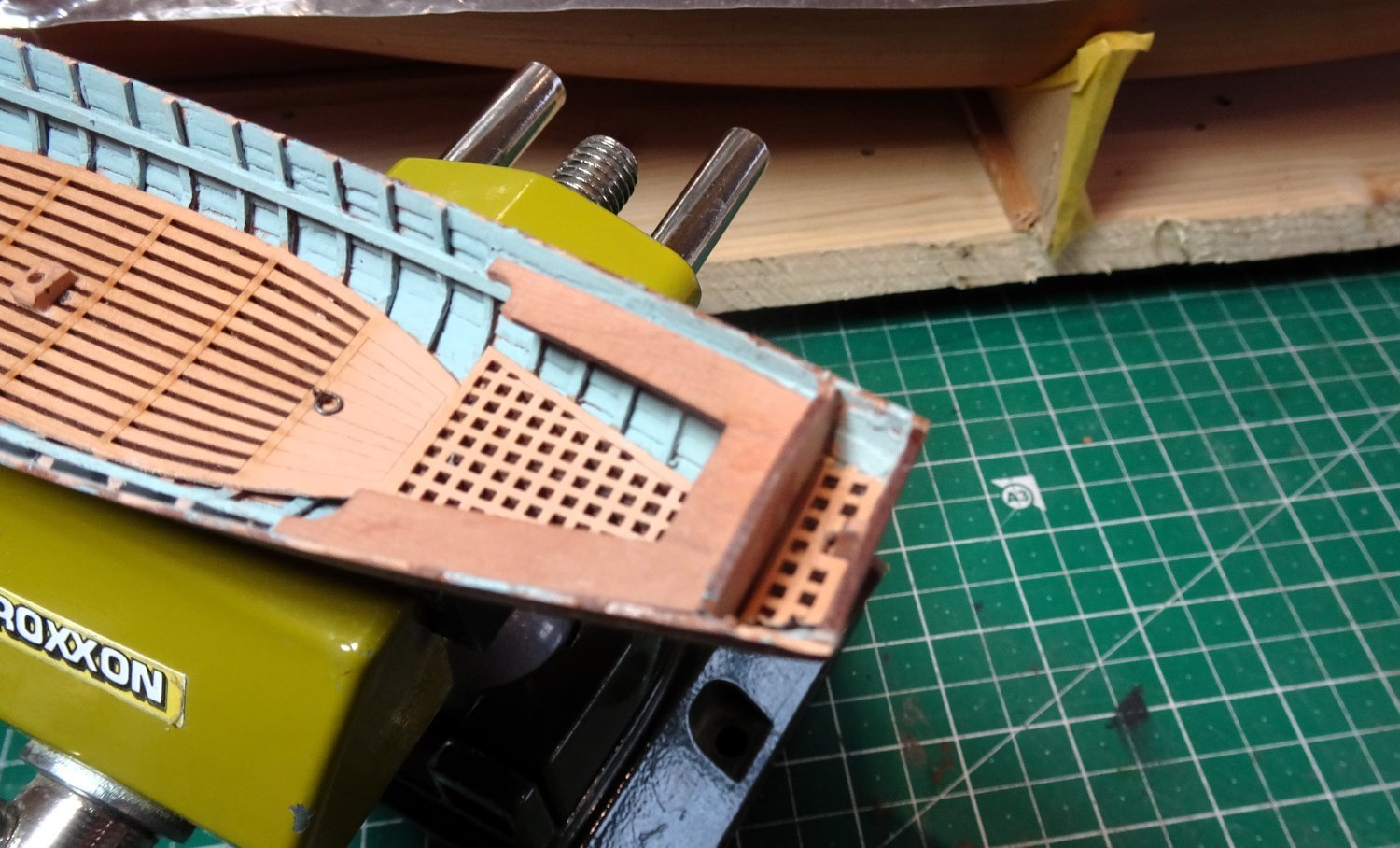
I divert from the kit when it comes to fitting the thwart supports, I leave them extended to the stern to support the sternsheet benches.

4017
The benches are provided as a unit including the aftermost thwart.

4025
I prefer to cut this away, modify the benches and add the thwart as a separate item.
I have added a panel below the aft seat which will double up as a compartment.
When it comes to the cox’n seat there is a slight issue; a grating is provided, but it sits far too high to be a practical platform for the Cox’n ‘s feet.

4032
It is prevented going lower by a ledge forming part of the keel set-up. Careful paring away of this incumbrance allows the grating to sit at a more realistic level.
A minor point maybe but the detail devil in me wouldn’t let it go.
4037
The bow platform comes as a pre-cut item which wasn’t a good fit on my build no doubt because of my failings. Fortunately, there is plenty of fret to re-make these items.

4028
Still very much w-i-p and a lot yet to do.
B.E.
21/03/2024
-
That fourth. photo gives a great impression of the mass of rigging involved with a square rigged sailing vessel.
Nicely done Kevin.👍
B.E.
- mtaylor and Old Collingwood
-
2
-
Thanks for the links Allan, I agree the convention for Pinnaces was for a single banked set-up with the thole pins off-set port and starboard.
There is 1:48 scale drawing of a 32’ Pinnace in the AotS book Diana which also shows a bench board running down the centre between the thwarts.
This feature also shows on the Adm drawings.
I will look to at least modifying the thole pin set-up on the kit Pinnace.
B.E.
- Theodosius, allanyed and mtaylor
-
3
-
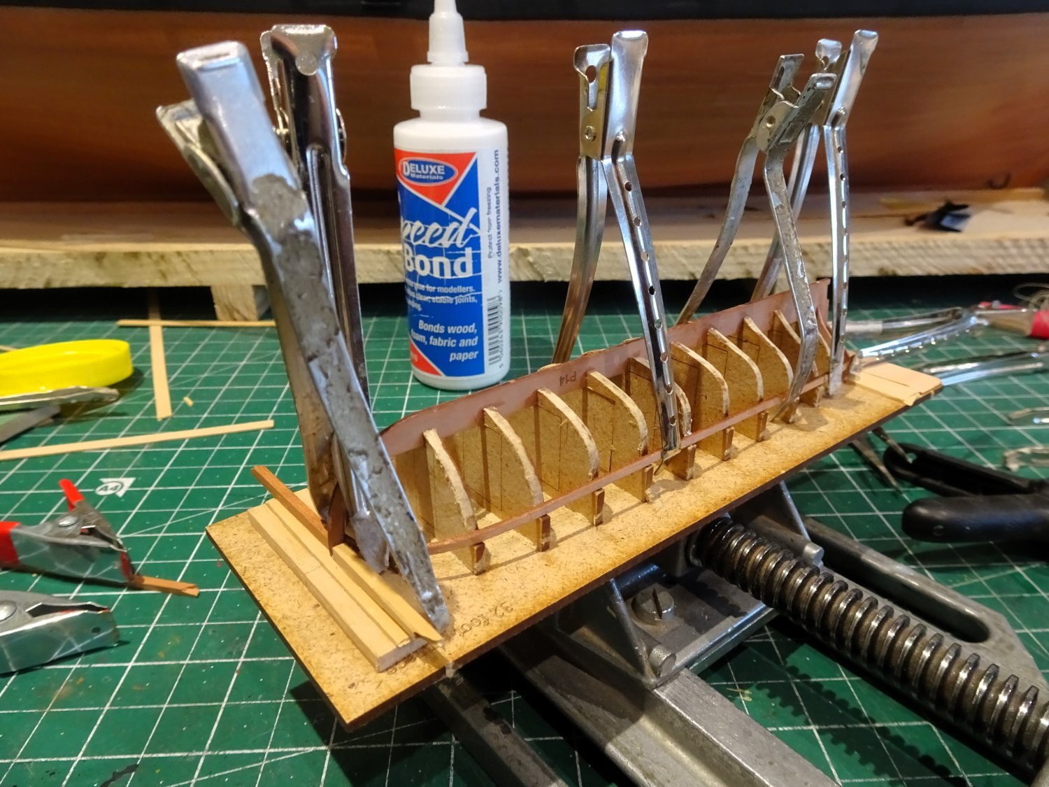
Post One Hundred and Fifty- eight.
Building the 32’ Pinnace (Part One)
This is the one boat example that I may include on the skids of my Indy.
I think the Pinnace is the nicest looking boat type and my go to for display on a ship.
I have built an example of every boat type in the Vanguard range, and my detailed logs are elsewhere on MSW, most recently on my Sphinx log.
My approach in building the Pinnace will be as previously recorded, so I’ll include less detail with this log.
There are a few areas of approach to building these bijou boats that may be of use to others.
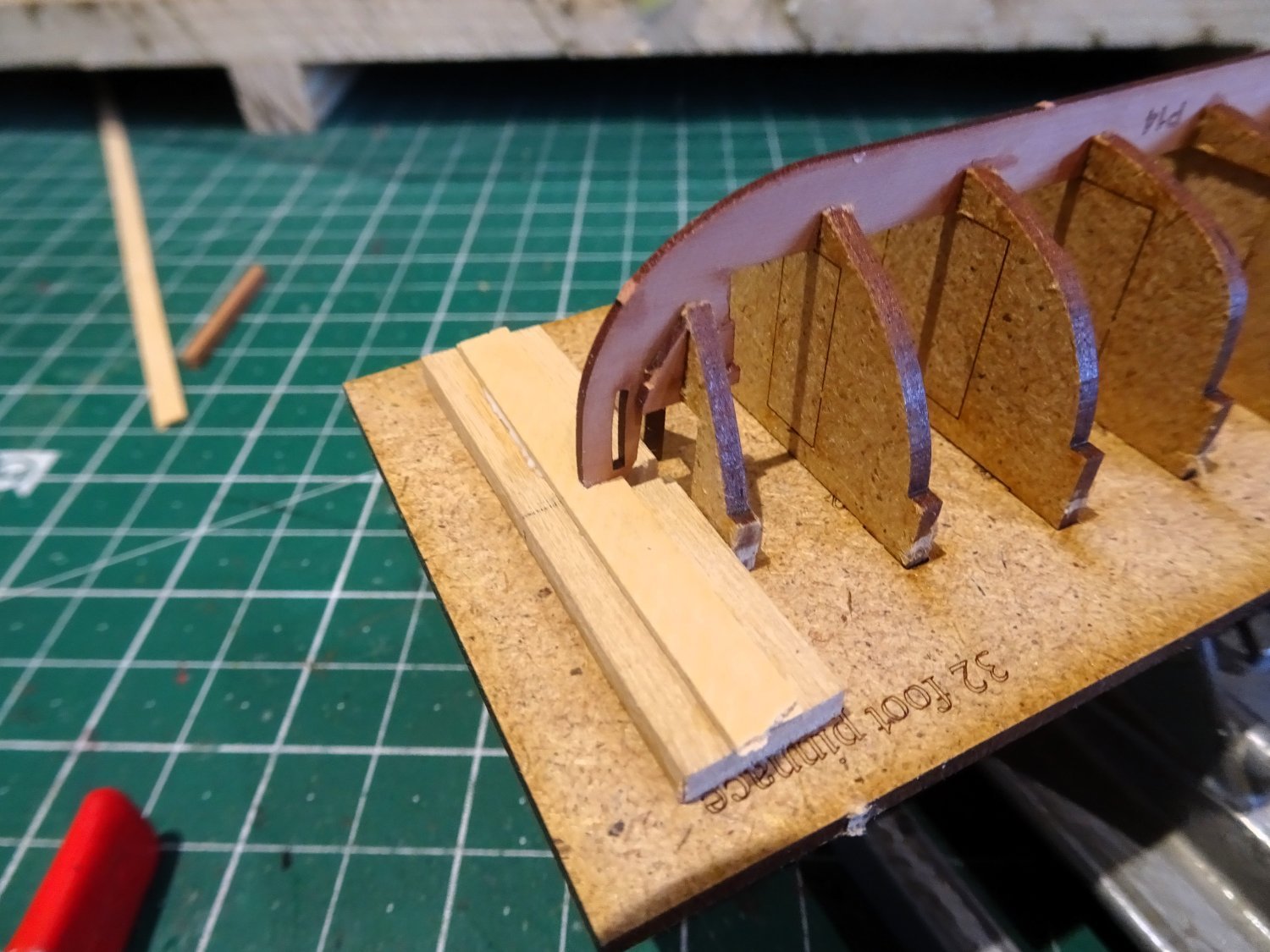
Setting up the frames.
These are delicate parts and I like to protect the framing, and I add support pieces to protect the bow and stern.

3981
These slotted strips protect the very delicate stem by avoiding the risk of flex when fitting the first strakes.

3979
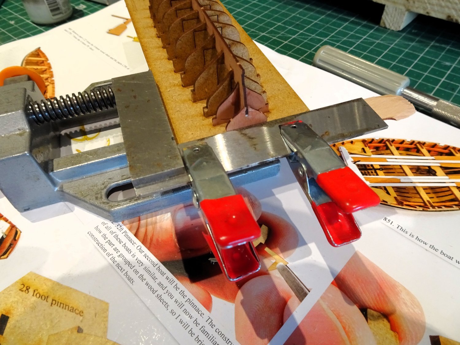
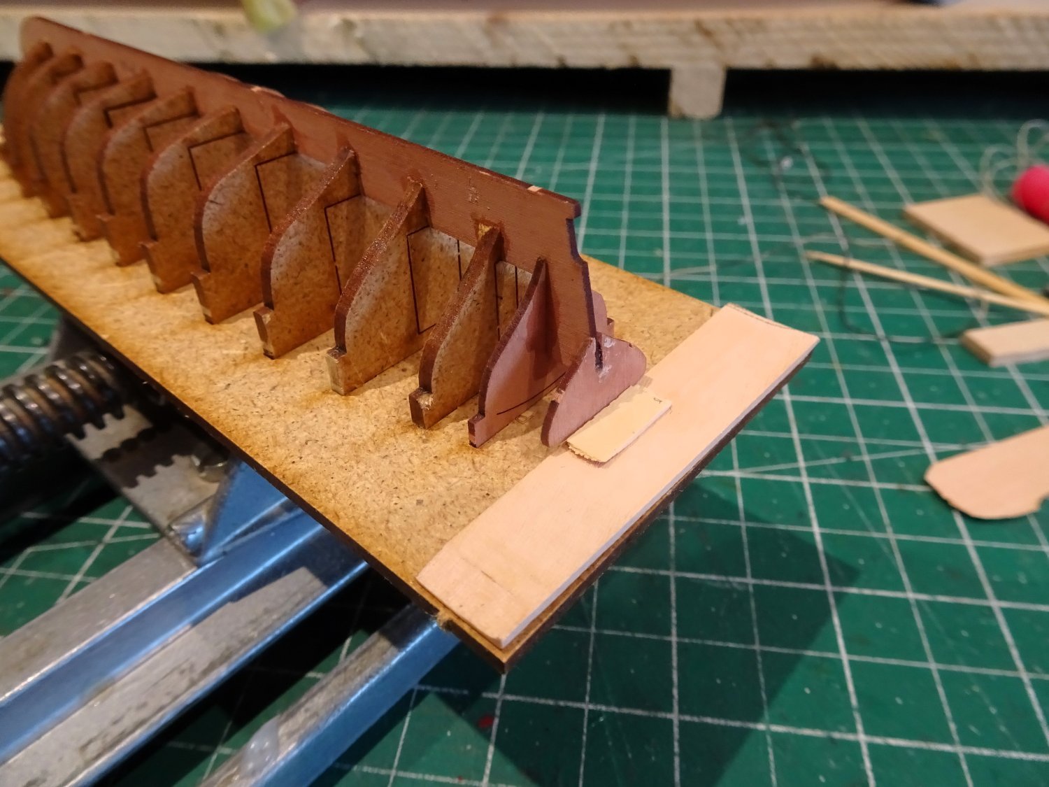
At the stern the transom is secured square.

3982
This is a weak part and support boards are added to reduce any risk of flex during fairing or attaching the planking strakes.
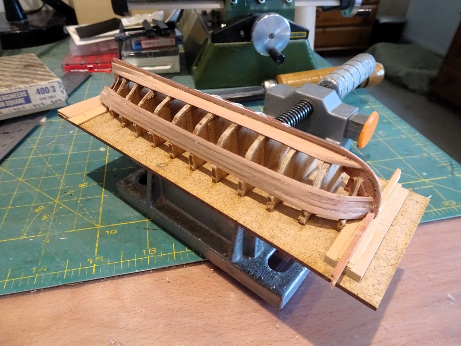
The planking strips are nominally 2mm x 0.8mm and as I found with the Sphinx Pinnace, they have very little excess in length to accommodate edge bending which applies very near the bow end.

3984
Both lateral and edge bending and also a degree of taper is required to maintain the flow of planking. These features were applied once the first plank had been installed.

3988
The first four planks fit into the stem rabbet, followed by the addition of the Garboard plank. For the Garboard I used a wider 3mm strip.
3993
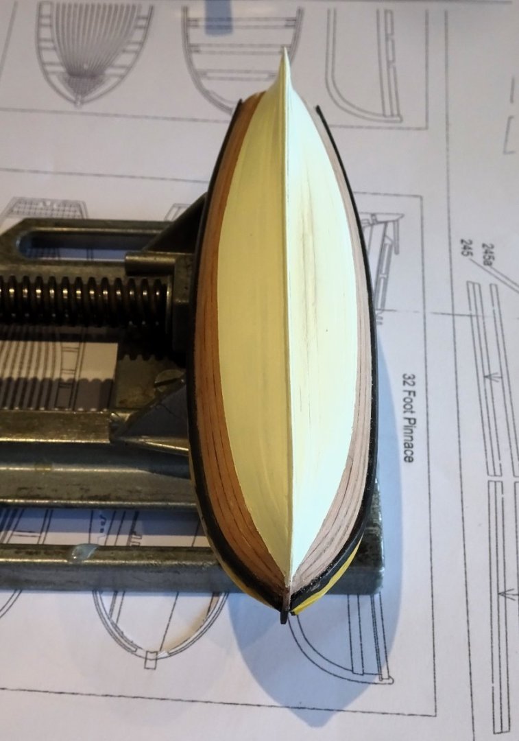
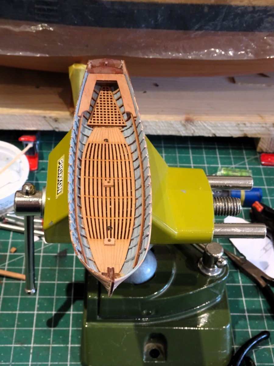
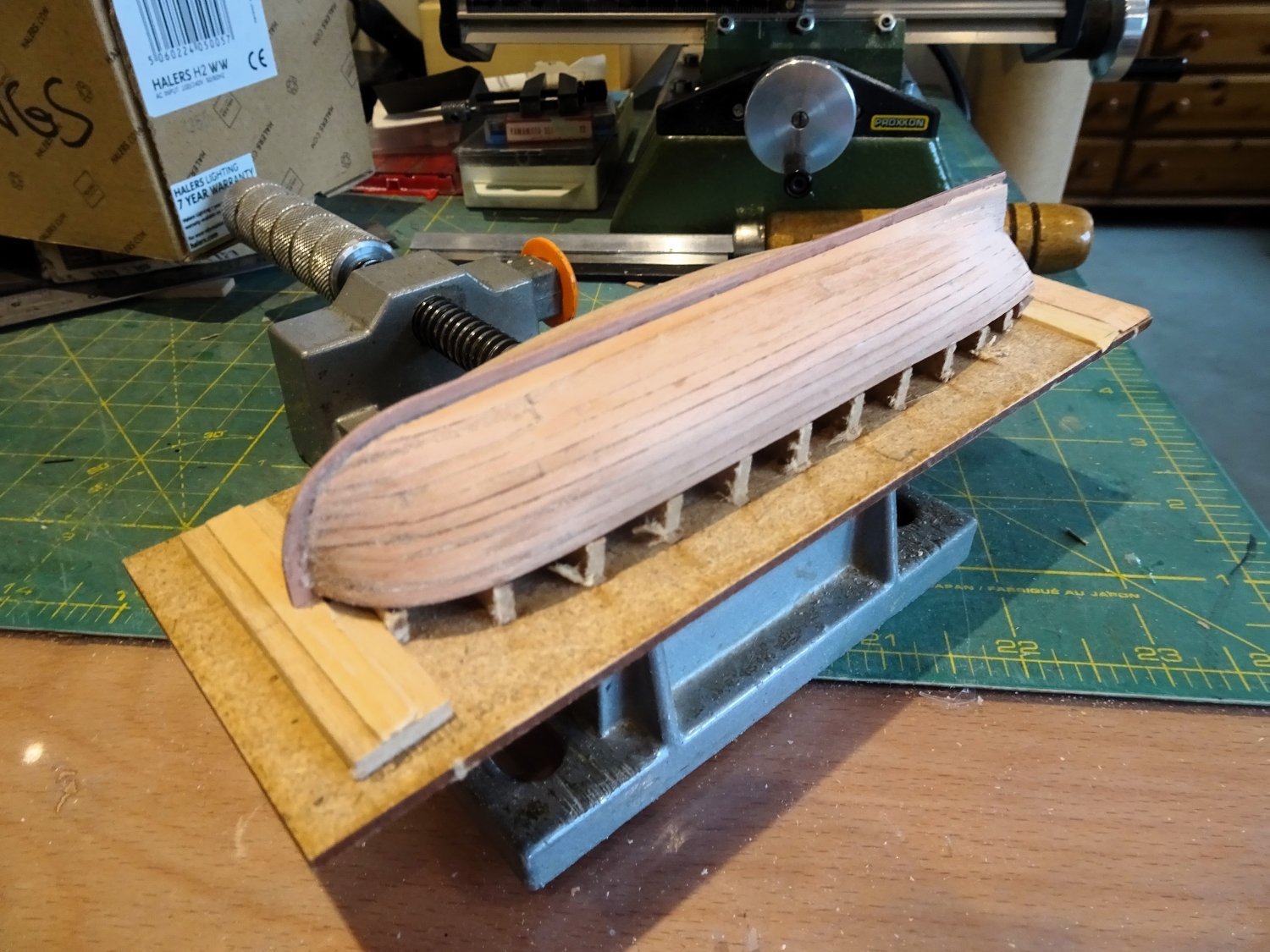
Planking continues to completion.
The final spiled plank that sits below the round of the hull is traced onto Tamiya tape and cut out of the 0.8mm Pear fret.

3998
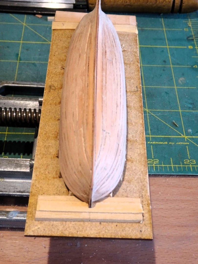
3999
Three days’ work and the planking is completed, albeit still in a rough state.
This will be cleaned up before moving onto the next stage.
B.E.
16/03/2024
- Thukydides, KARAVOKIRIS, Glenn-UK and 25 others
-
28
-
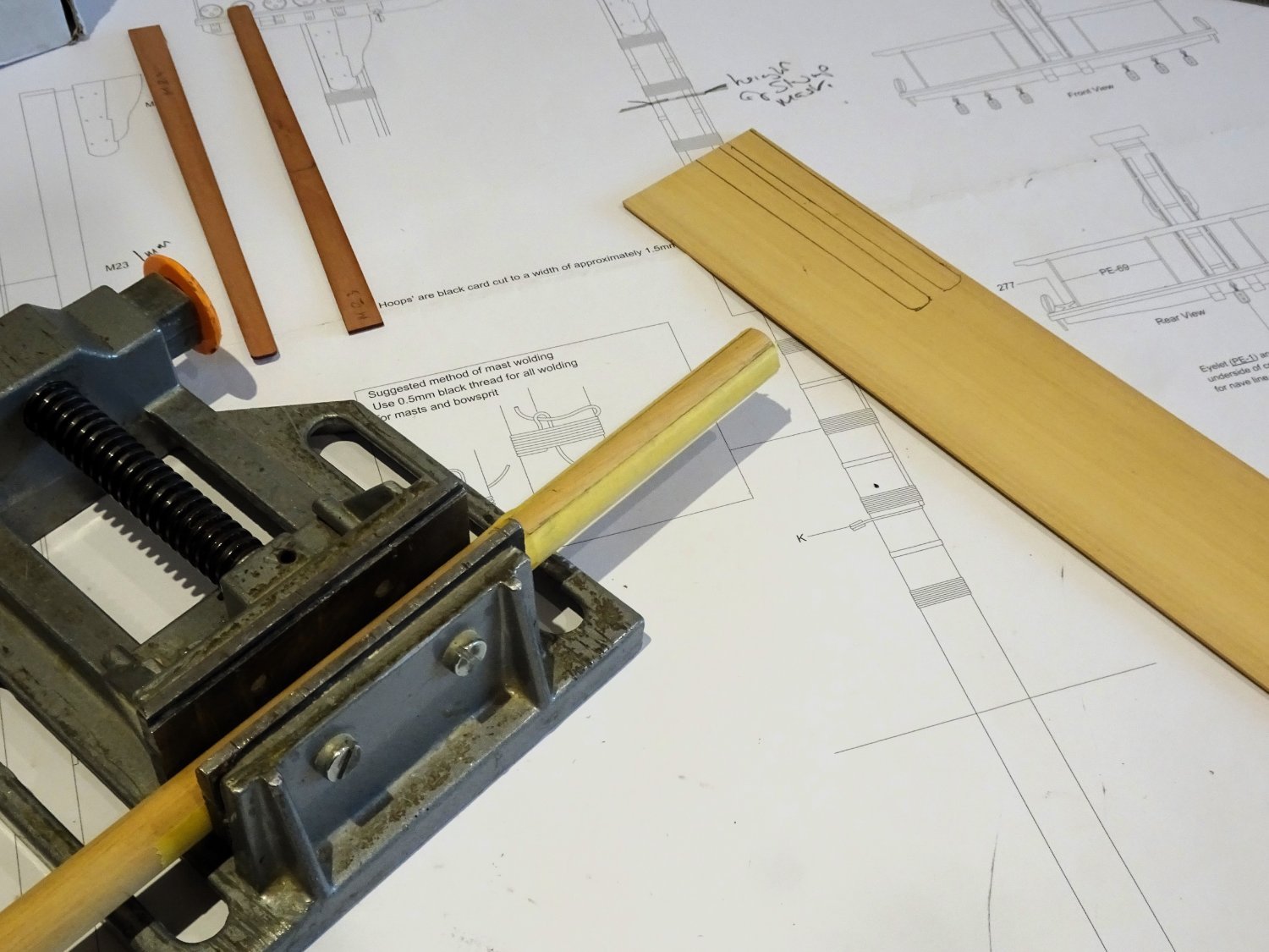
Post One Hundred and Fifty- seven
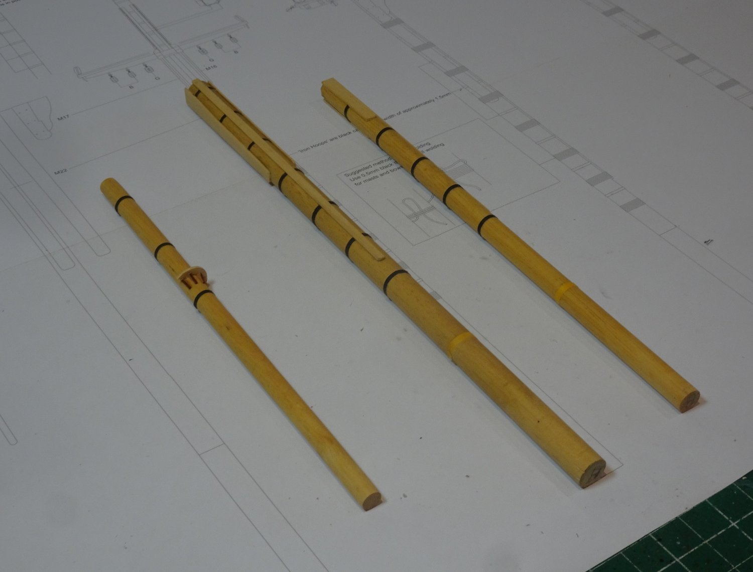
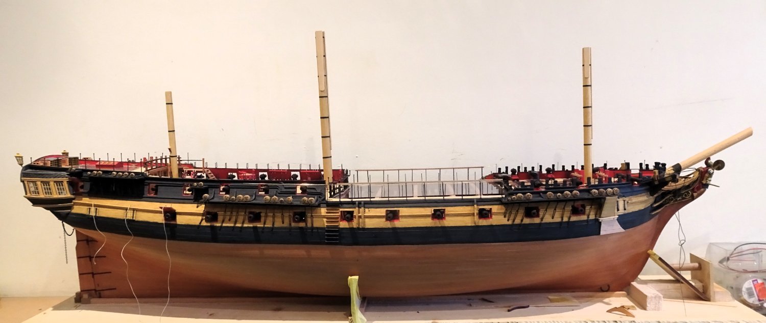
Mast Making.
Starting with the Mainmast:-
For the reduced height masts I firstly need to work out the relative positions of the wooldings, iron bands, and the point where the side cheeks and front fish terminate.

3967
I replaced the Pear laser cut cheeks and fish with Boxwood versions to better match the Ramin masts.
The iron bands need to be fitted before the cheeks are put into place. With a 12mm ø mast my go to use of heat shrink tubing will not work, so it’s back to thin strips of black card.
Once the cheeks are fitted the remaining iron bands need to be applied, they sit beneath the Front fish. I work the bands so that the join will also be beneath the Fish.

3970
The Fish is then fitted

3972

3973

3974

3976

3977
The saddle for the Driver Boom was also replaced with a Boxwood version.
3978
3971
The woolding remains to be done, but I am out of the correct line sizes.
B.E.
12/03/2024
-
-
Ah, but where did they get them from😉
B.E.
- hollowneck, dafi, CODY and 2 others
-
5
-
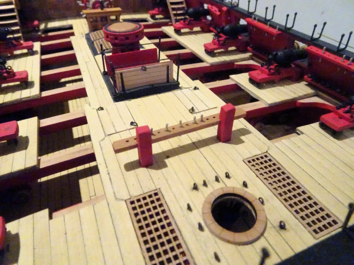
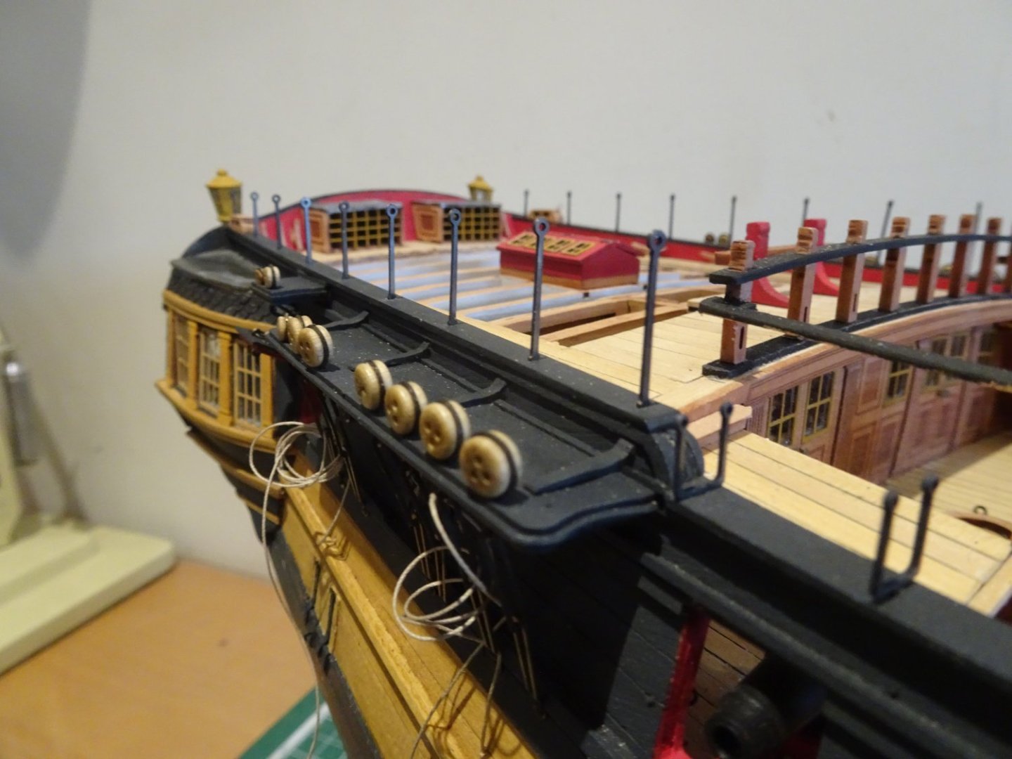
Post One Hundred and Fifty- six
Bits and pieces
From this point on the comforting crutch of the glossy manual has ended.
There are many small fittings to add and in this session I will mainly be referring to Plans 5 and 9.
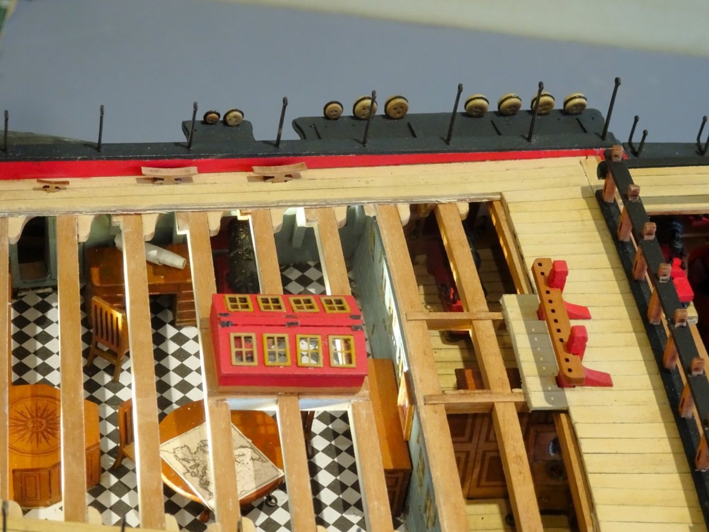
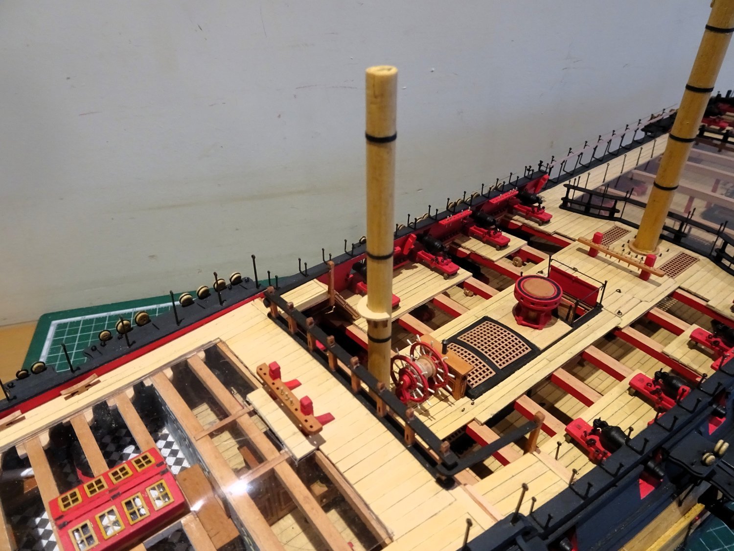
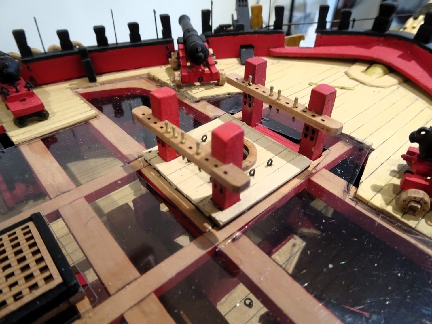
Working from in to out there is brass wire(0.8mmø) to be inserted thro the faces of the skid beams across the waist (plan5)- shown as belay pins on (Plan 9).
3955
The arrangement seems to have been taken from that of the Victory where one rigging source indicates that the triple aft three relate to the belay of the Staysail sheets and those on the second from forward beam for the Main Topmast Stunsail downhauls.
Fortunately for me this has no practical application.
3946
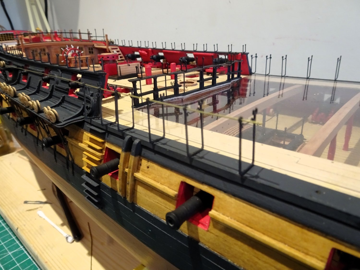
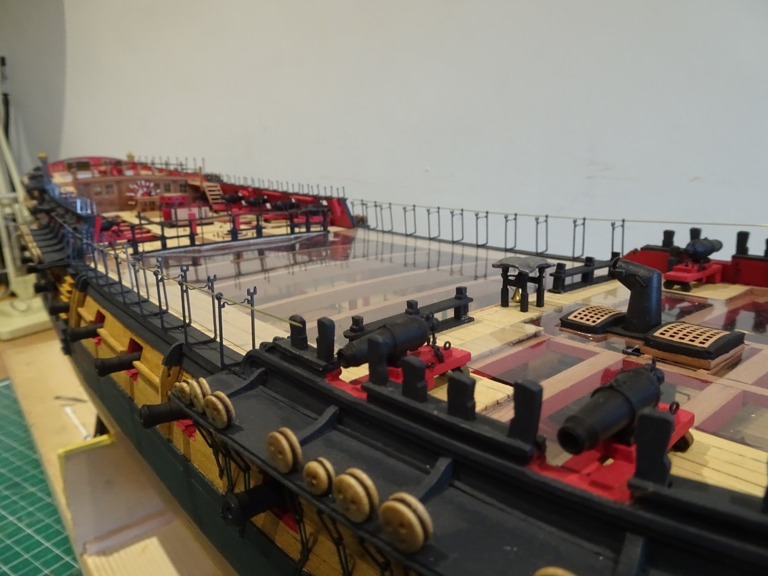
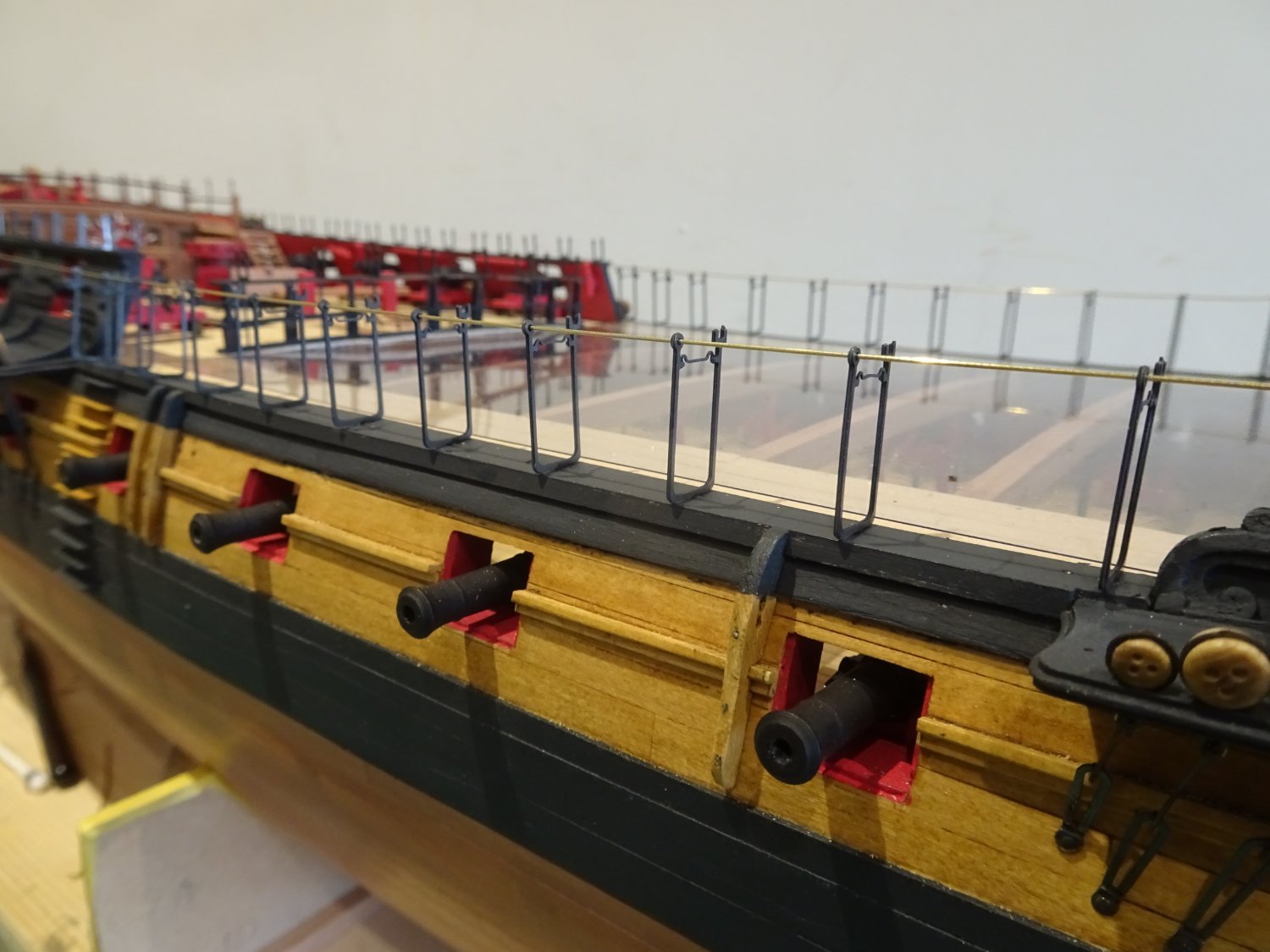
The inner guide rope stanchions (PE59) are fitted along the waist gangboards followed by a wooden rail (2X1mm Pear) atop the inner hammock crane arms, the fit into the brass etched crutches is perfect.
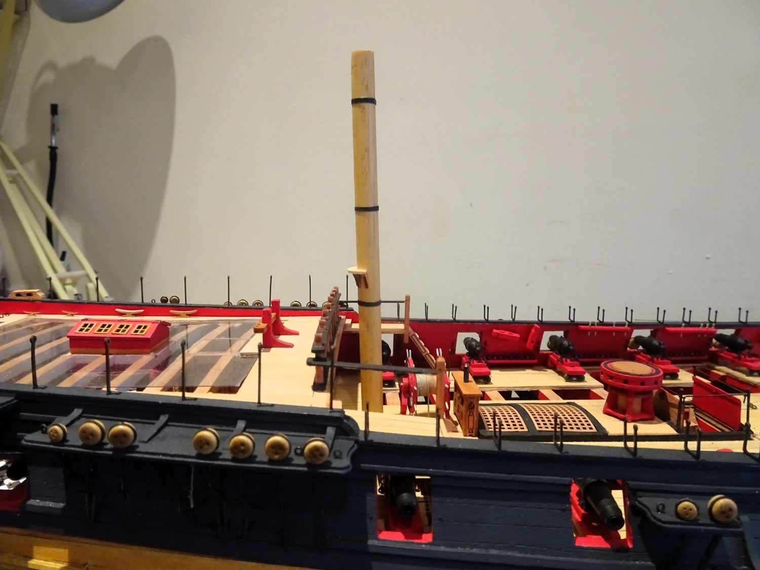
I have diverted from the plan by adding iron stanchions between the timberheads around the Fo’csle.
3953
Not provided in the kit I used spare items from the Sphinx kit- a slightly shorter stanchion.
It seemed reasonable to me that given the low height of the rails, stanchions would have been fitted.
The kit provides etched versions of the belay pins, they are a mere 8mm in length, and barely 0.8mm in width, but still have a visible shape, and I think they look quite good at the scale.

3947
3956
Blackened to give them some tooth and painted a bare wood colour I added a few to the pin rails for effect.
3949
There are quite a few eyebolts to add along the channels together with the iron work for the Main studding booms.
I dare say I will find other little additions as I continue to re-check the plans but for now I am moving onto dressing the stump masts.
B.E.
10/03/2024
-
Thankyou Yves, the drawings in the AoTS Bellona provide a good guide, and the given anchor dimensions for a Seventy-four are taken from Steele.
If your anchors match the scale the arrangement looks ok to my eye, at least on paper.
'Indy' is more problematic, ideally the anchor arm should fit between the first and second deadeyes, to bring it as close to the hull as possible, but there is no room. This accords with the Adm plan.
The aft bower is easier as it will fit as per the Bellona drawing.
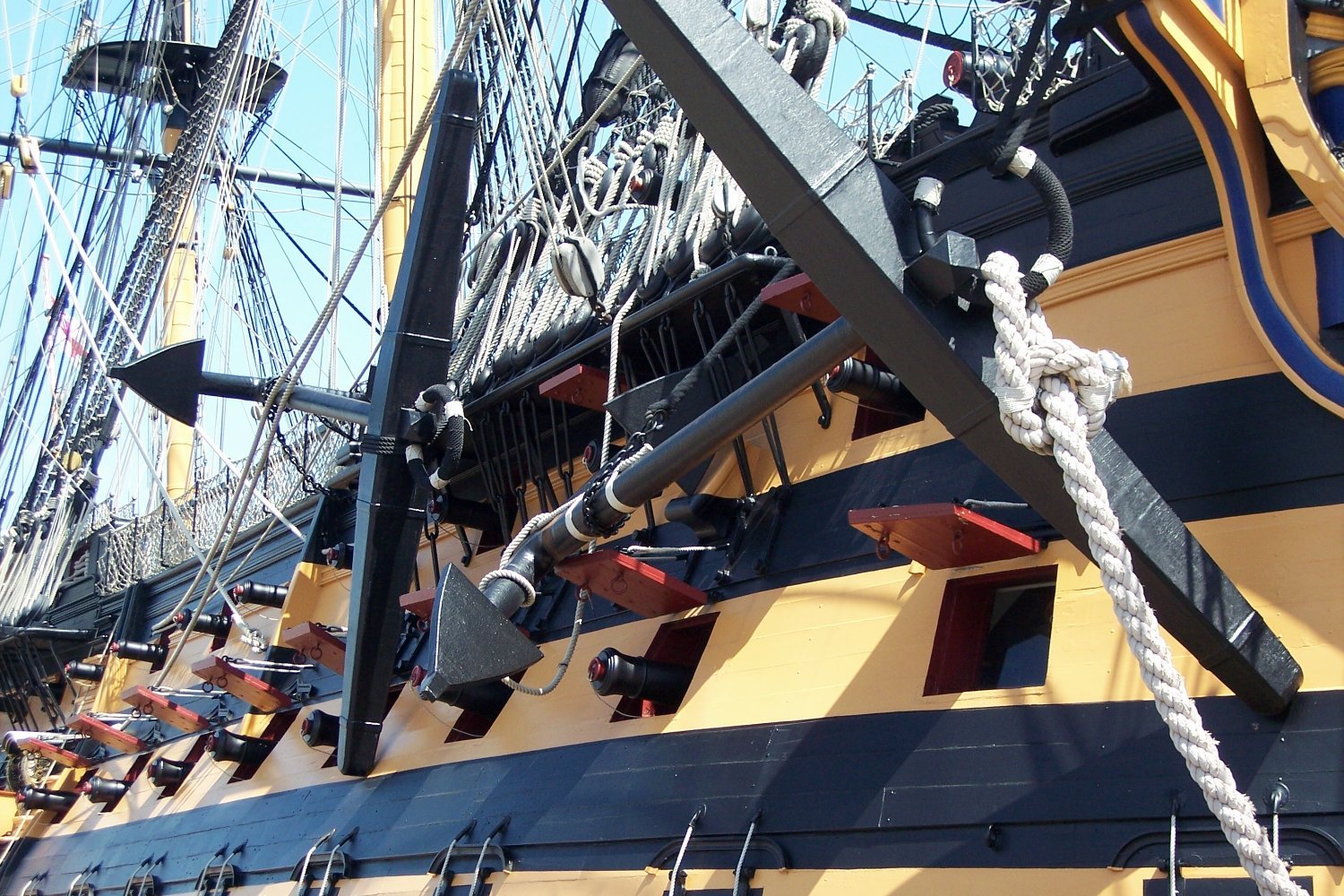
Victory had a different arrangement.

1834
Here, Billboards and linings are dispensed with and the anchor fluke sits in a heavy shoe.
How they manipulated that 81cwt lump of iron into position without marring that pristine paintwork I can only wonder at.🤔
These of course are replicas.
B.E.
- Clark, Knocklouder, CiscoH and 6 others
-
9
-
Thank you Bug, glad to see work has restarted on your Pegasus.👍
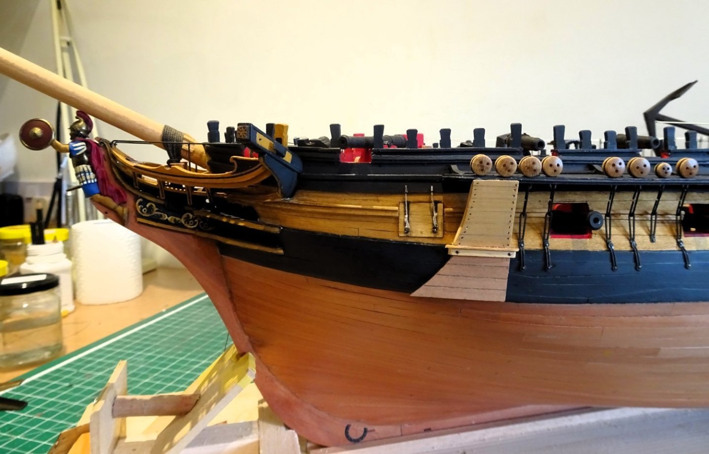
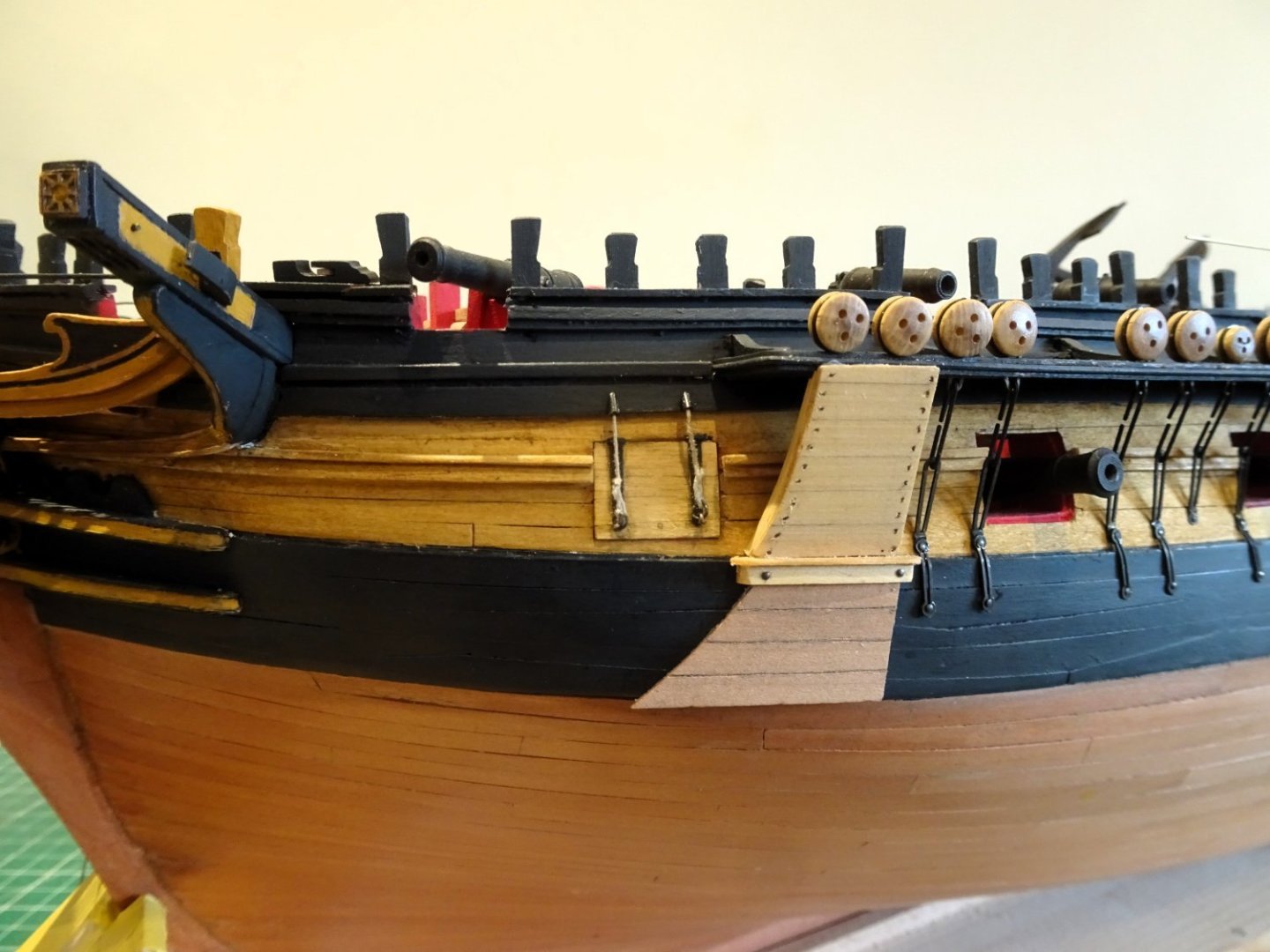
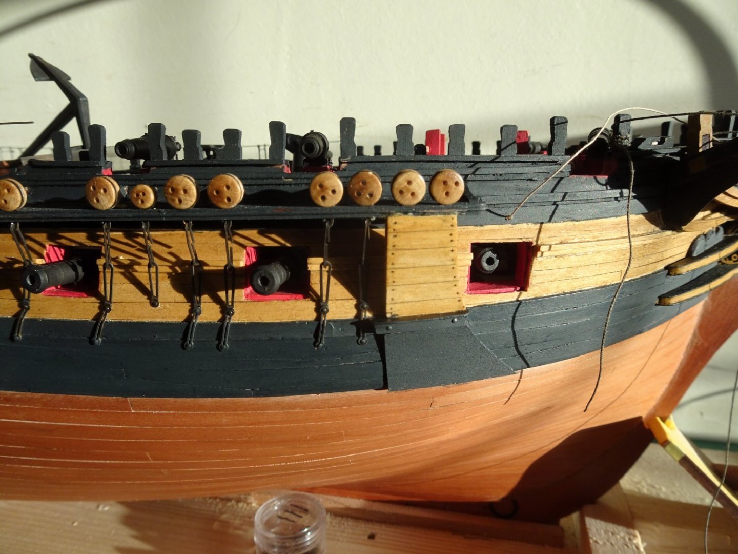
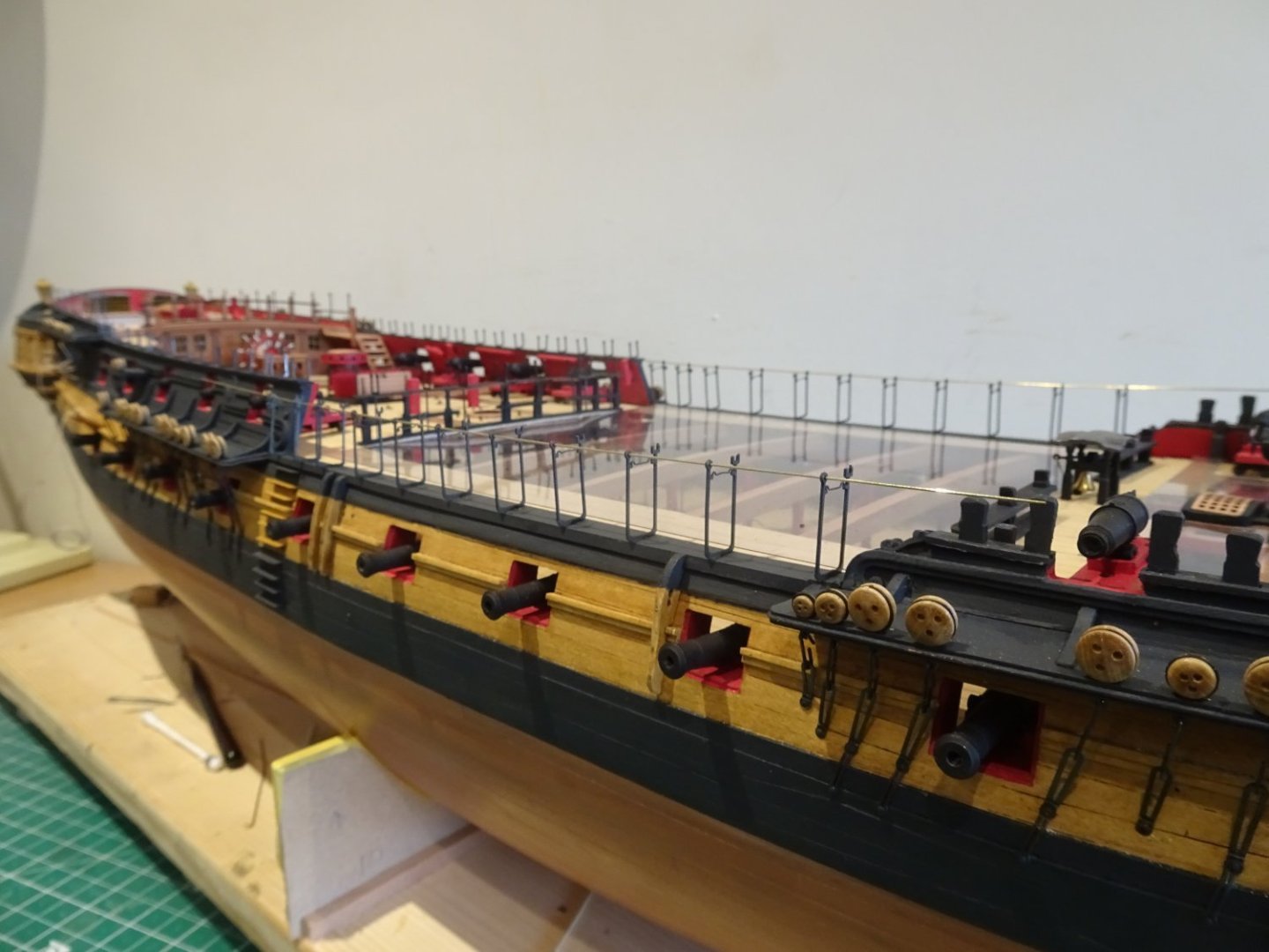
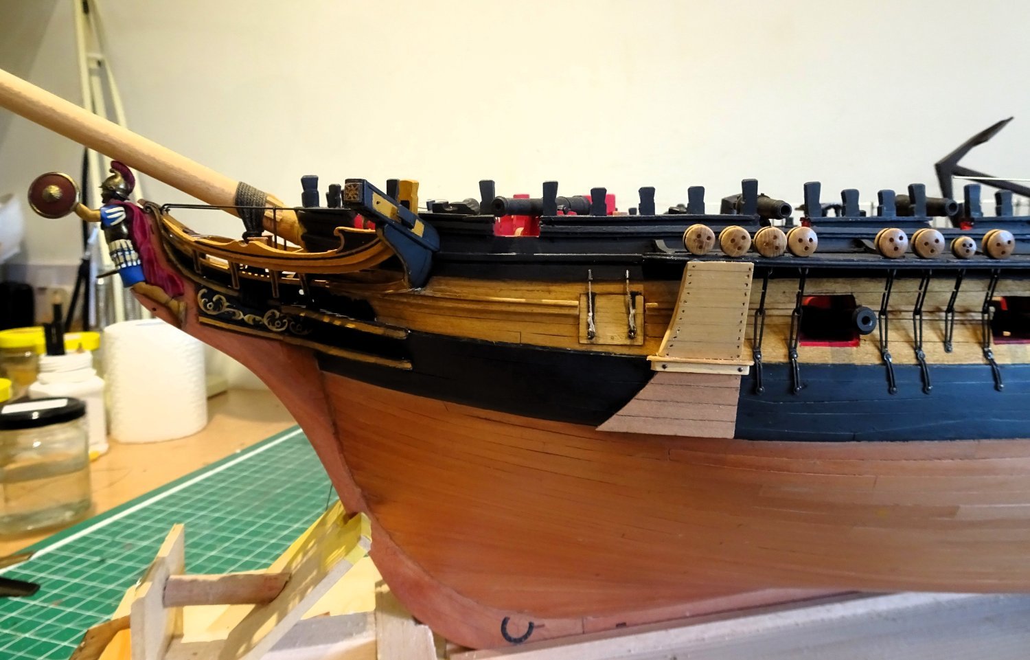
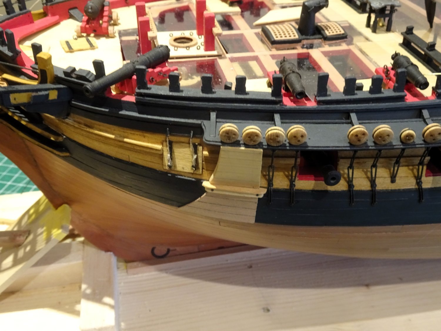
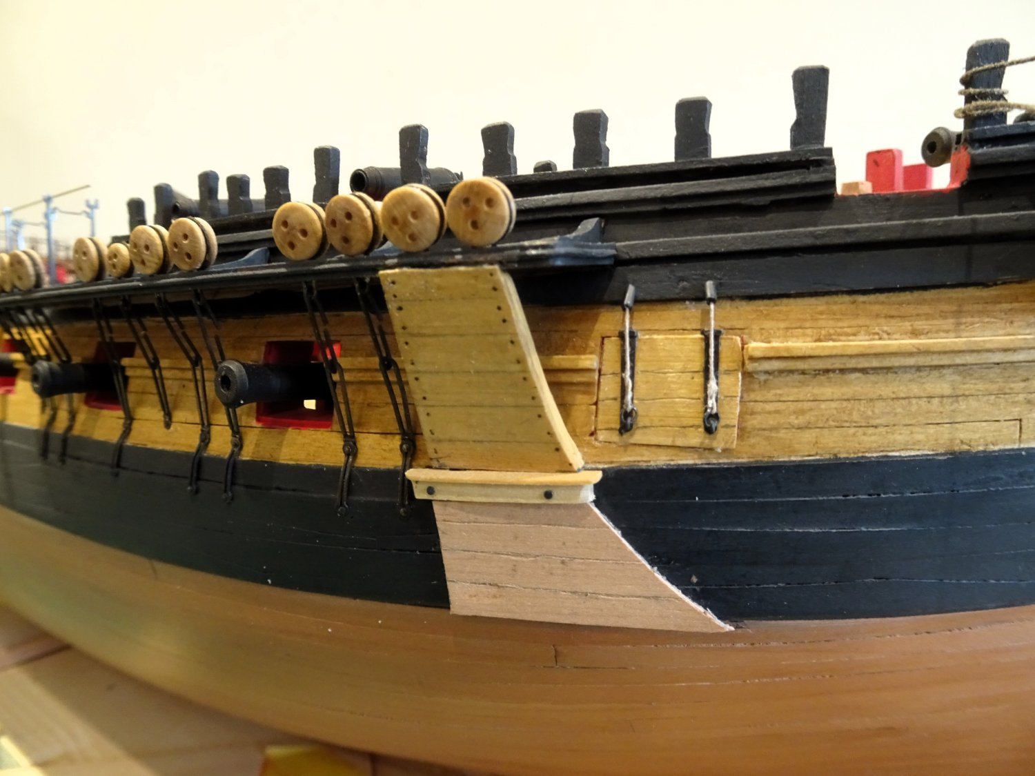
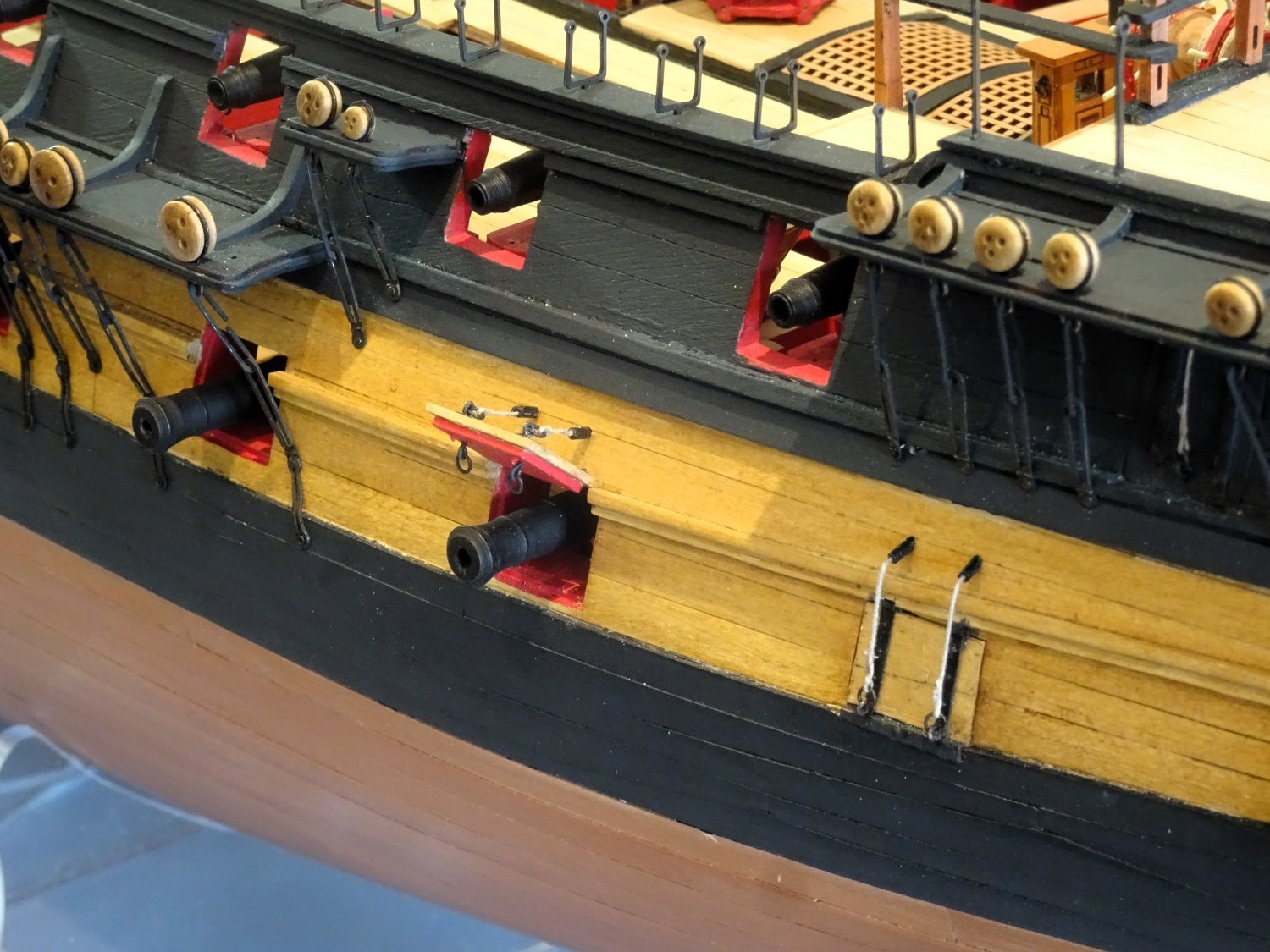
Post One Hundred and Fifty- five
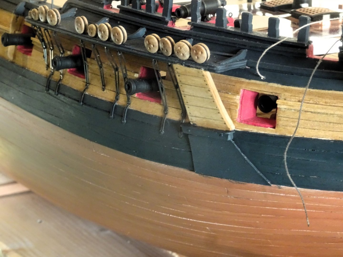
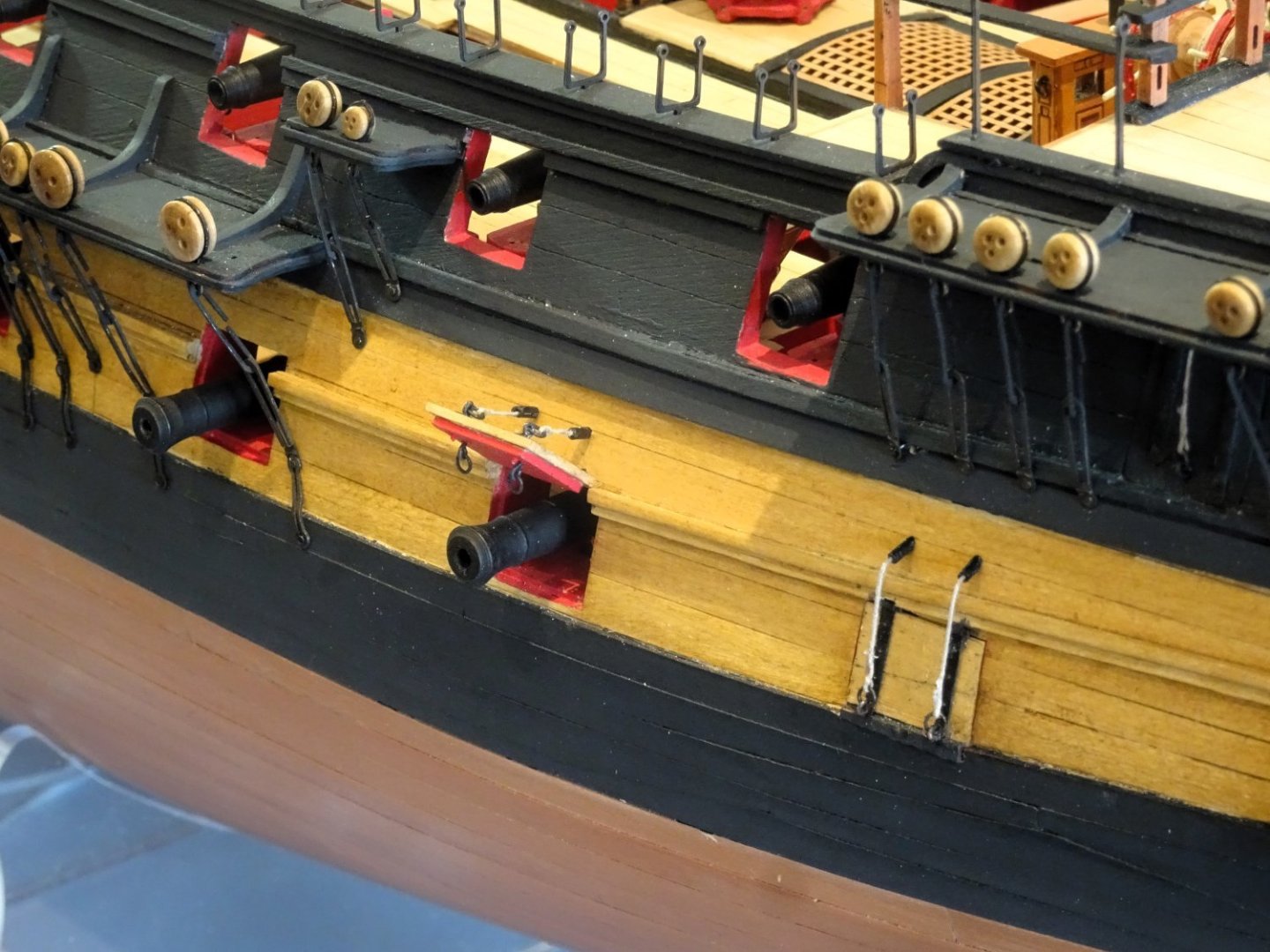
I continued to fit the Port side billboards and linings.
3939

3936
3937
I think I have made a better job of the Port side, so off came the starboard side for a re-fit.

3941
Starboard side re-done, happier now.

3942
I have also taken the opportunity to replace the bow port lid and add double lifting lanyards.
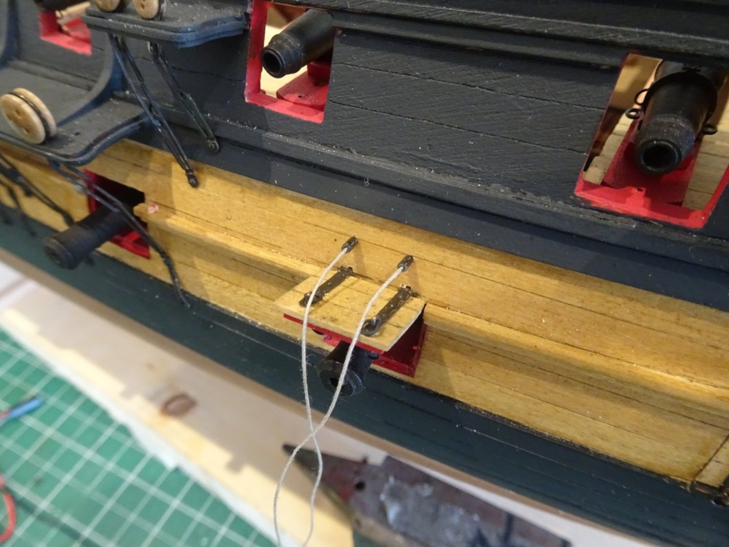
3852
Small sections of telephone wire sleeving are used to represent the port lanyard tubes, but they did need drilling through to take the 0.30mm line which was stiffened with ca for the purpose.
3932
Another small job is to add the rudder chains. I used some Caldercraft Brass chain, 18 links /per inch.
I will get around to trimming them at some point.
B.E.
08/03/2024
-
Post One Hundred and Fifty- four
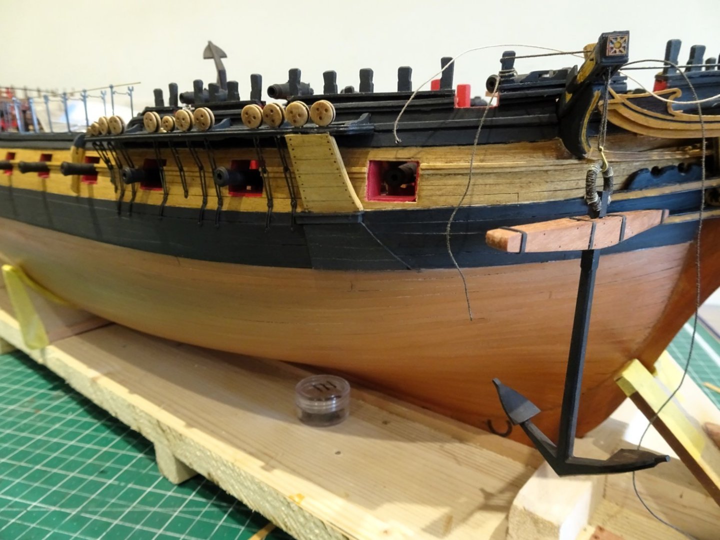
This post follows on from Post 152 having a close relationship to anchors.
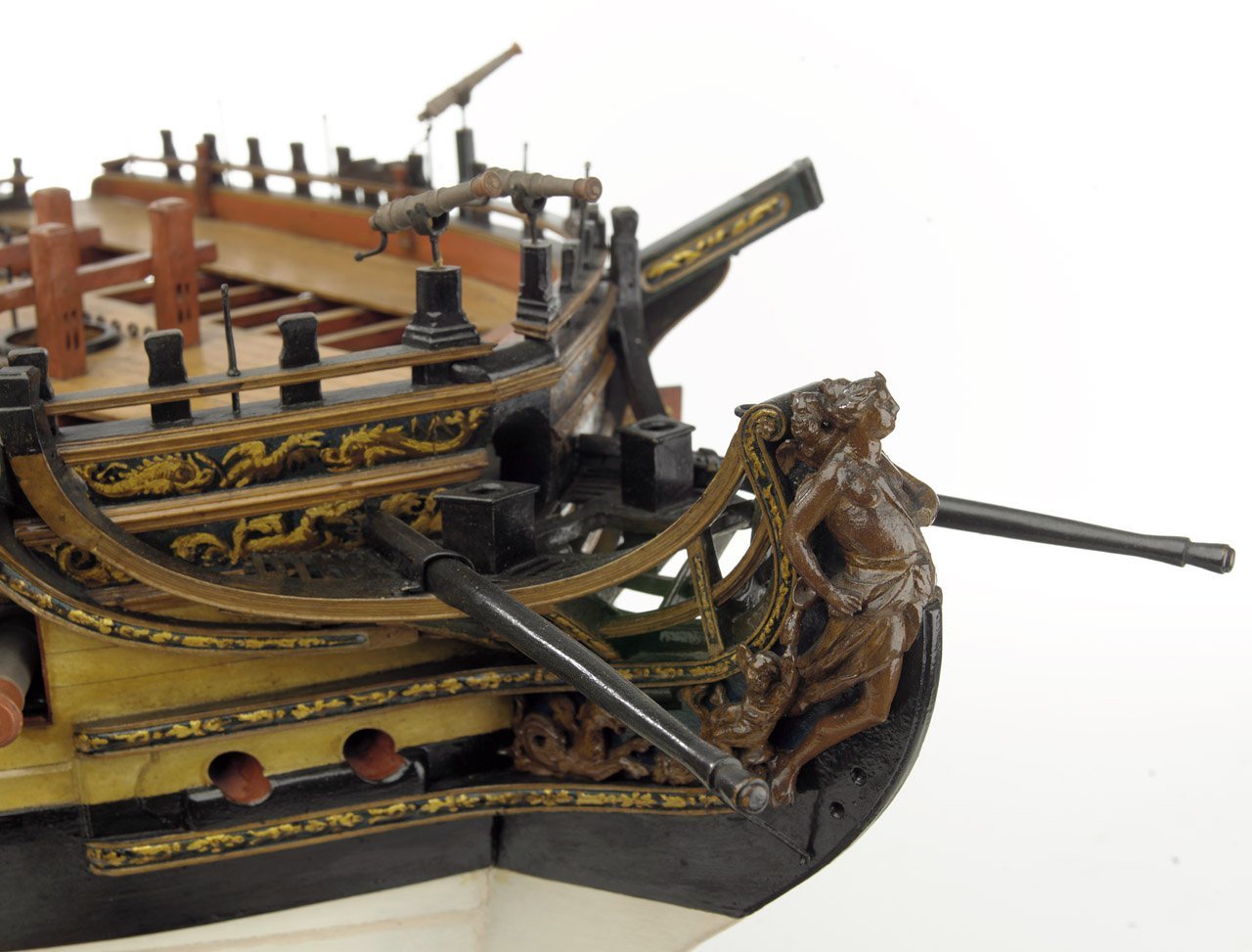
One of the reasons I made up the anchors is that I have also been thinking about anchor linings and billboards.
These do not feature with the kit and do not tend to appear on contemporary plans.
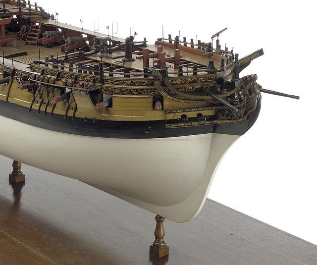
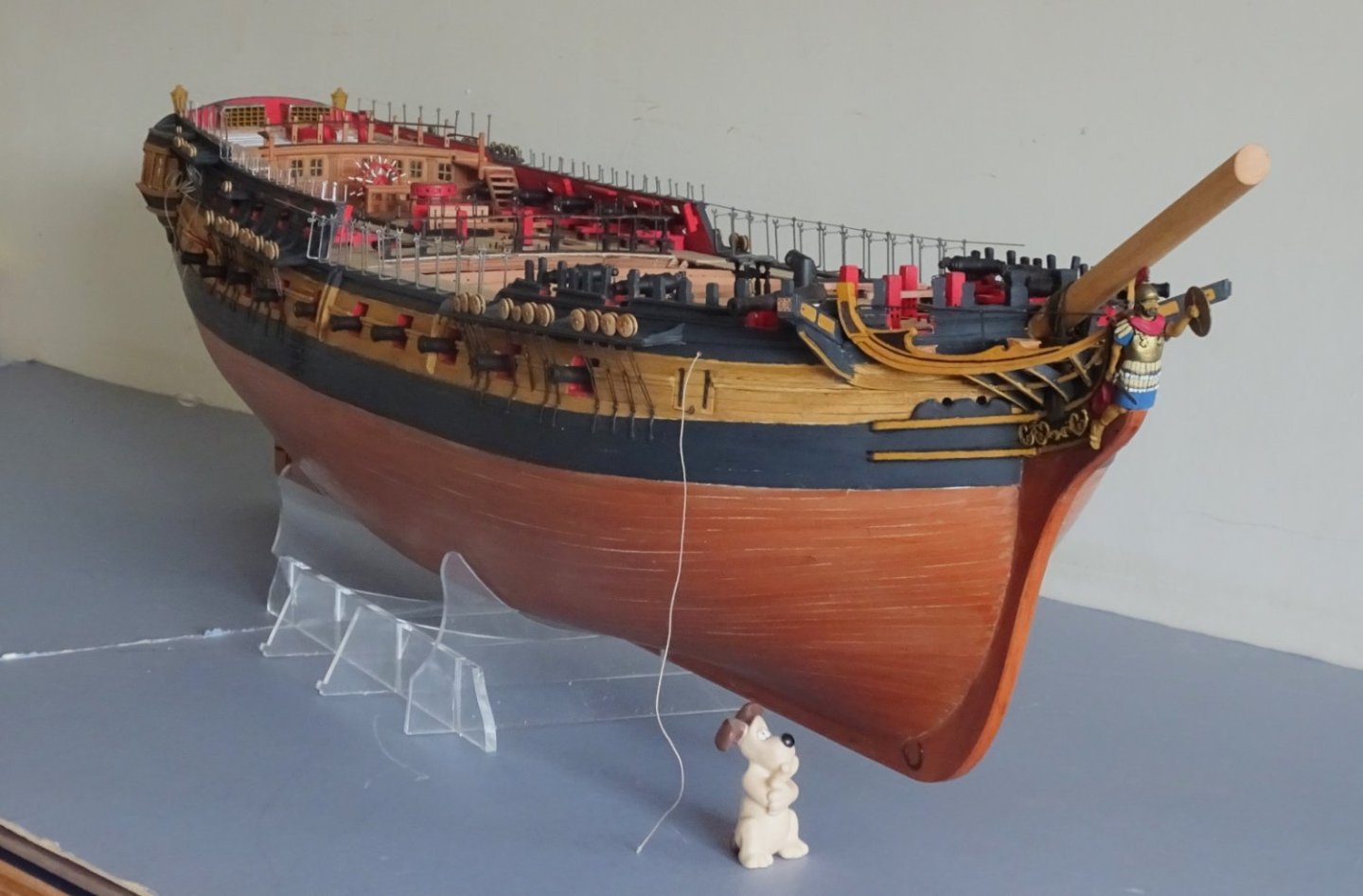
Many contemporary models show them, as on Amazon above.
They were an important feature on ships of the period to protect the hull from the anchor flukes.
Chuck’s Winnie
My go to reference, here you can see the lining running over the wale.
7396
I added billboards to my Sphinx build as above.
3906
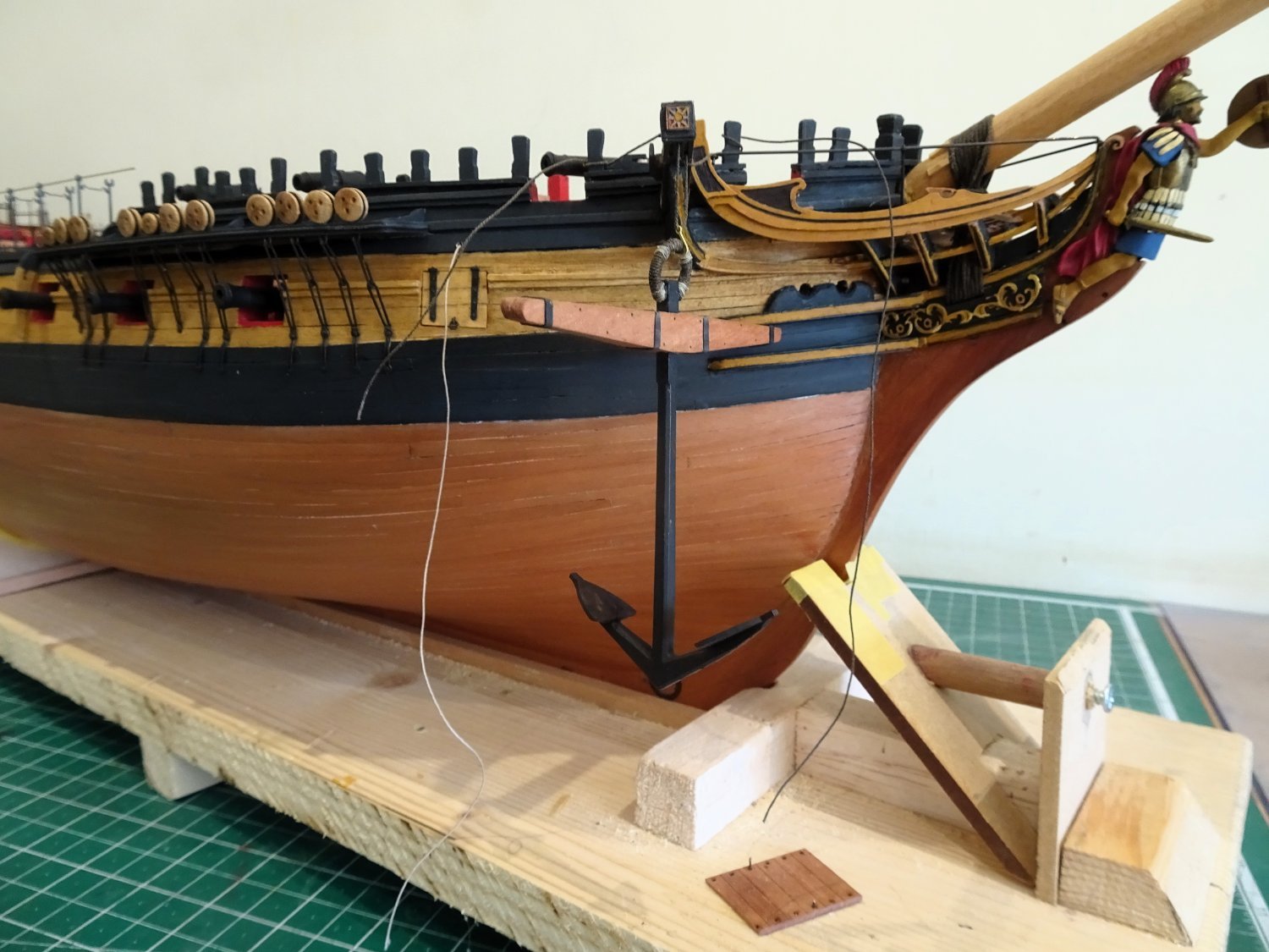
Having an anchor made up is useful in that the arc made by the anchor as it is swung horizontal from the cathead for securing, determines the position of the lining and billboards.
In considering Bolsters and Billboards for Indy I am hamstrung by the absence of specific sizes of timber to use. With Sphinx it was relatively easy having the TFFM book to refer to.
I know where these fittings were placed so it is basically down to what looks good to my eye.
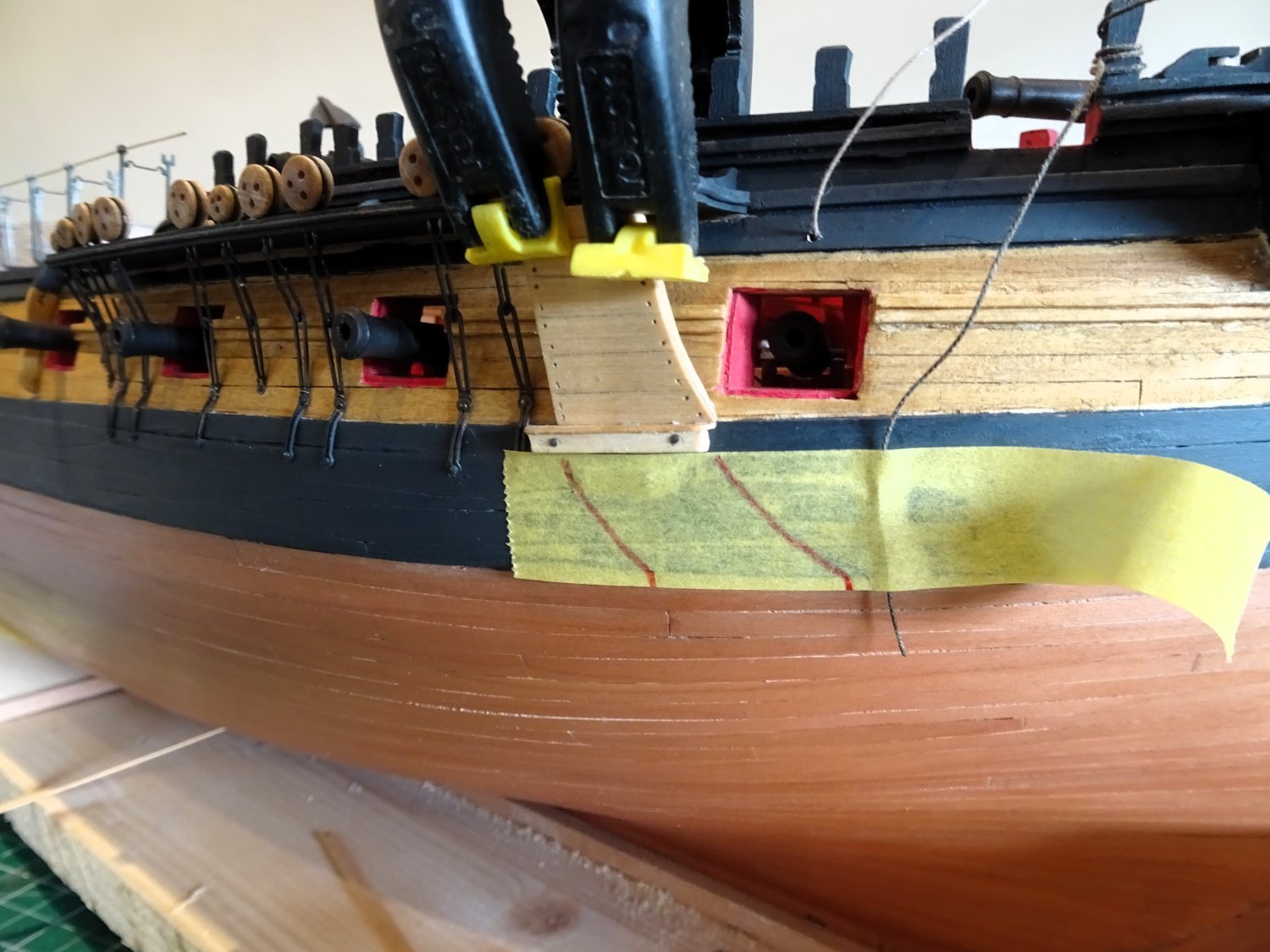
I firstly made the Bolsters using some Boxwood square stock of 2.75mm. This was topped by some 3.5 x 0.7mm boxwood strip.
3910
The length of the bolster worked out at 26mm.
Notches were cut out of the back side to fit over the first two preventer plates of the Fore channels and a slight curve was induced to match the curve of the bow.
The bolster was fixed to the Black strake only with pins.
3913
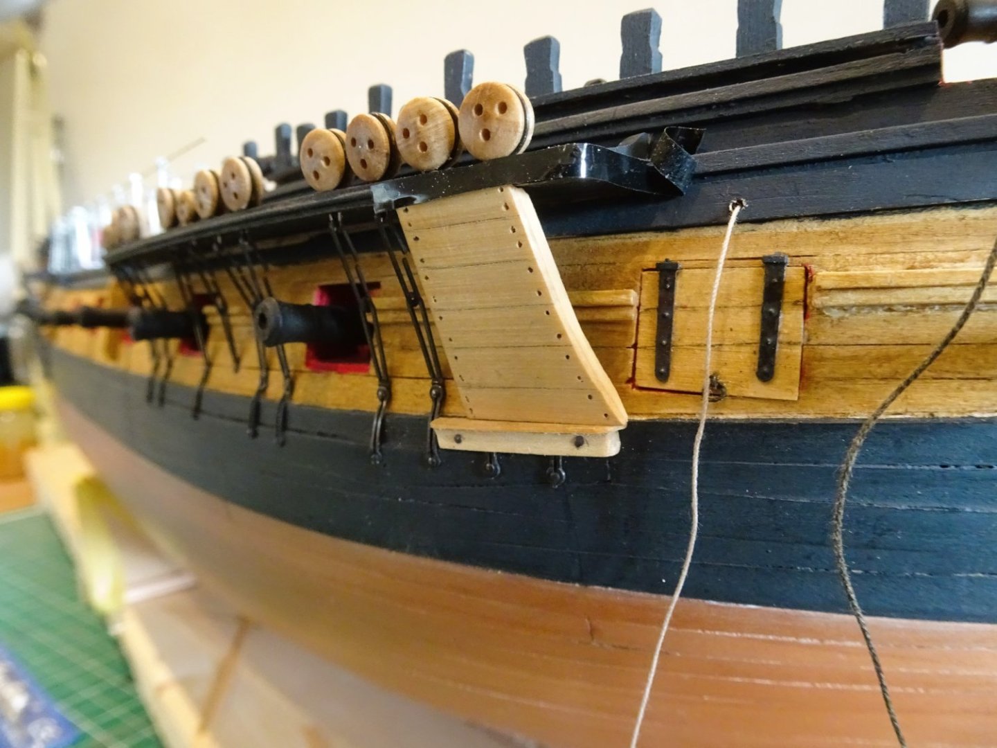
With the bolsters in place the Billboards can be made. For this I use some 1mm Boxwood scrap inscribed with 3mm wide boards which reflect the topsides planking.
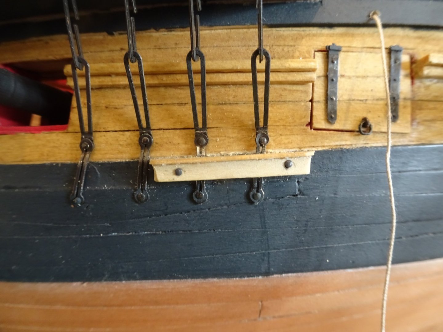
The Linings

3914
These cover the main wale in the case of Indy and scribe an arc at the fore end that follows that of the anchor swing.
I settled on using some 0.6mm Pearwood scrap which suits my eye.
3917
 3919
3919
3929
In fixing the linings I have used double sided tape. This gives me the option of easy removal if I decide I don’t like them, and the jury is still out on that.
Altho’ I’m not fitting the anchors I don’t think it will be an easy fit to get the bowers to look right.
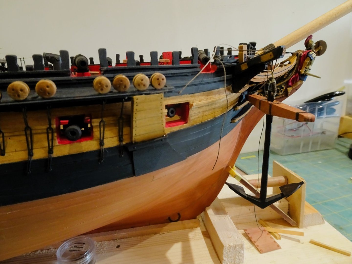
3923

3924
If the bill is to rest on the Fore channel there is little room between the deadeyes.

3930
A possible fixing with the arm atop the fore end of the channel secured with shank painters around the timberheads.
I will be interested to see how others tackle the anchor rigging.🤔
B.E.
07/03/2024
-
-
-
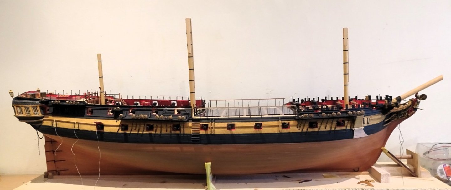
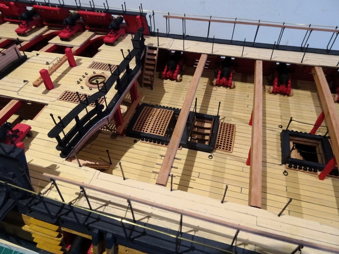
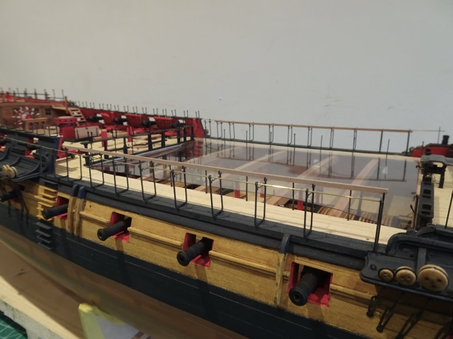
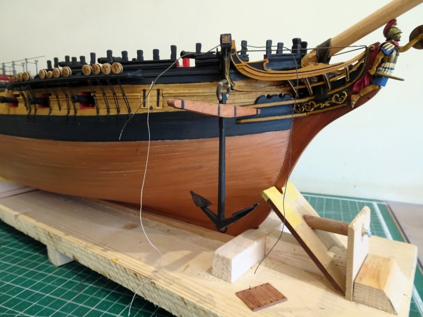
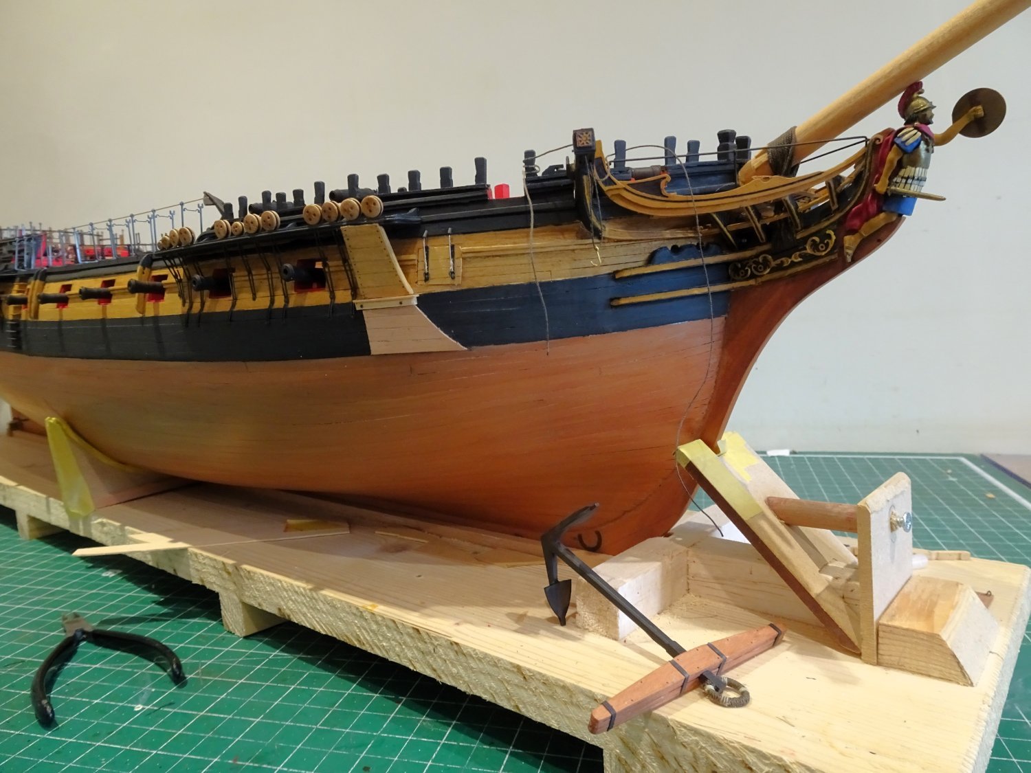
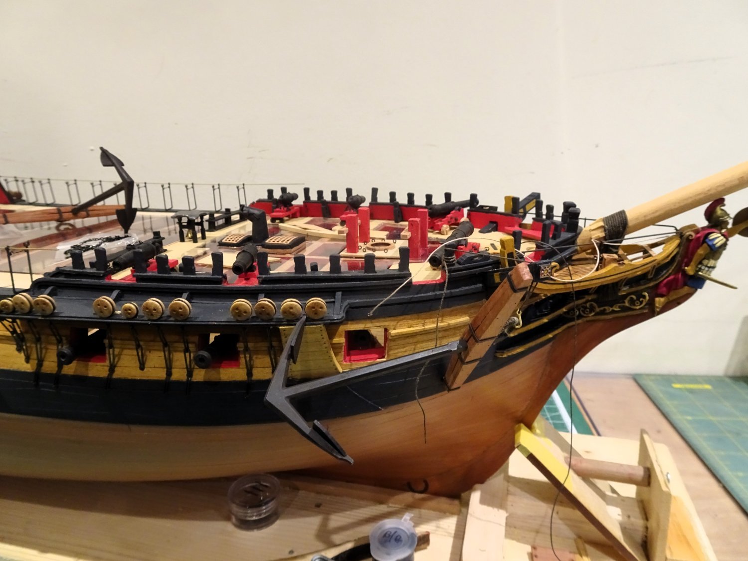
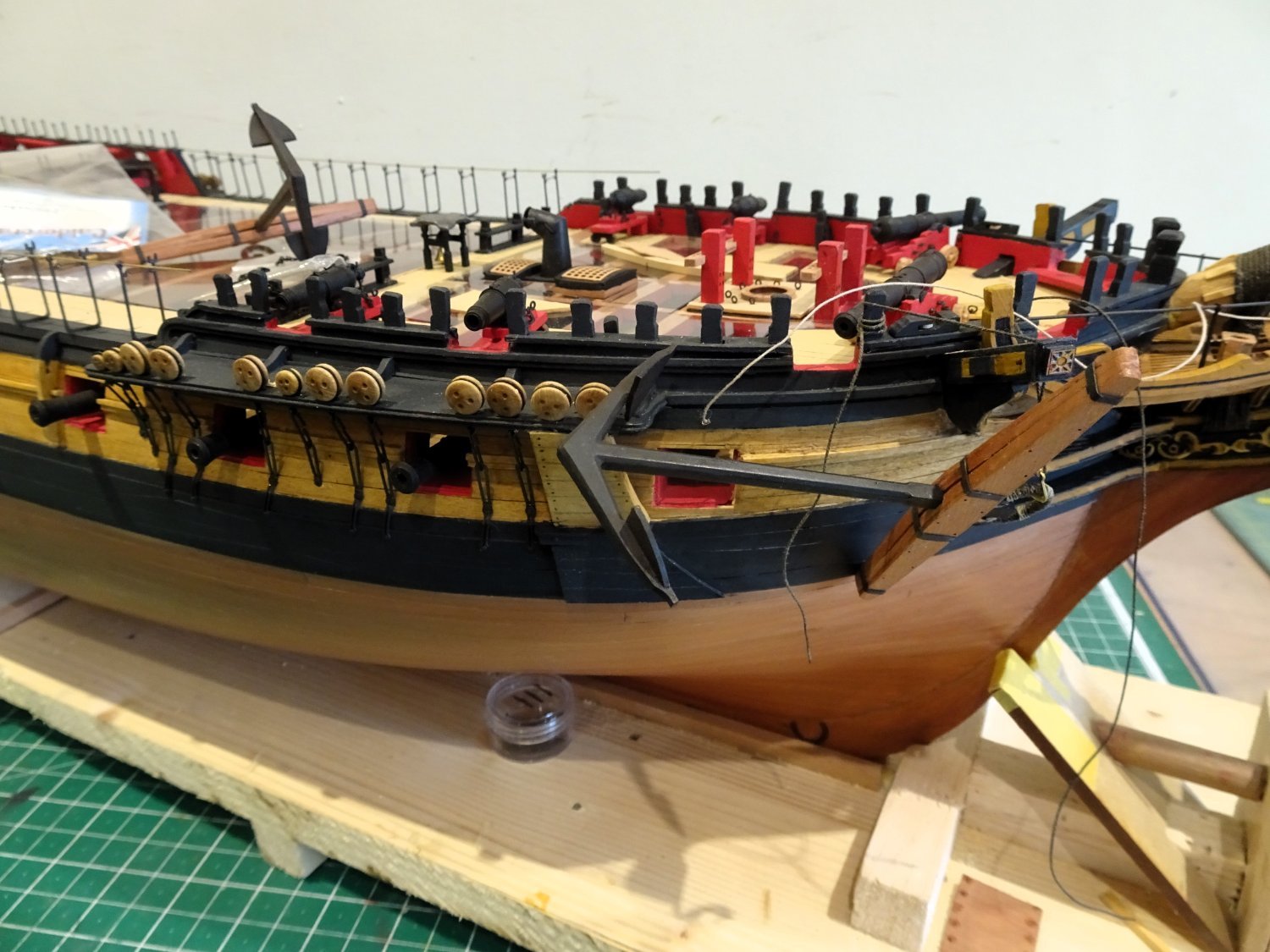
Post One Hundred and Fifty-three
Anniversary
Today marks twelve months since I started this log.
I have worked several hours, mostly each day, over the period and have included many modifications to the basic kit, some obvious, some not so, and some now hidden.
That such a large and detailed model can be constructed to this stage in such a relatively short time is all down to Chris’s planning and design and the quality of the fittings.
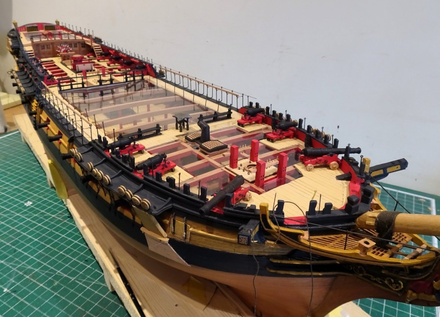
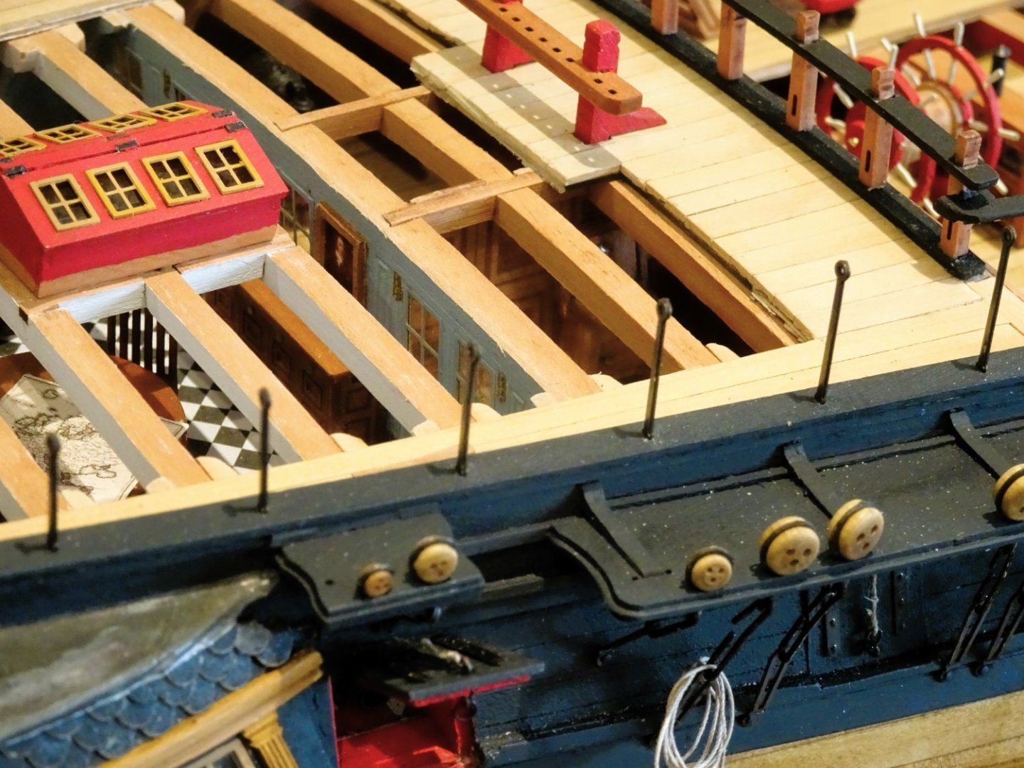
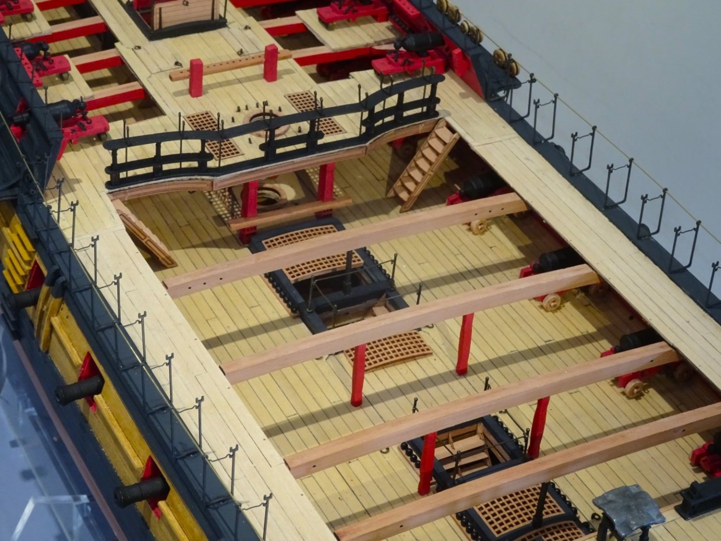
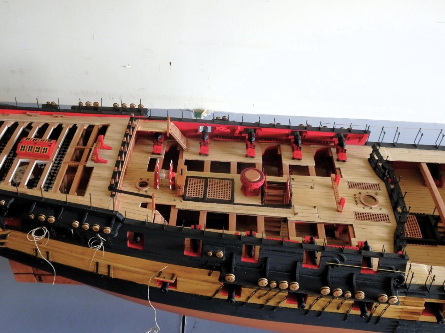
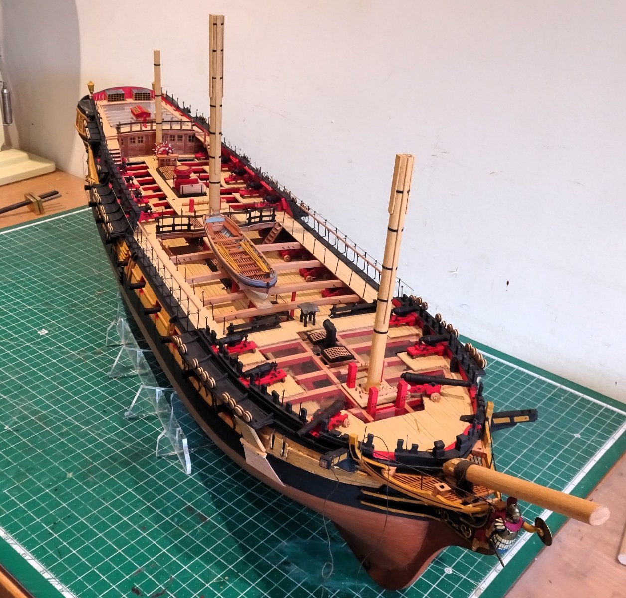
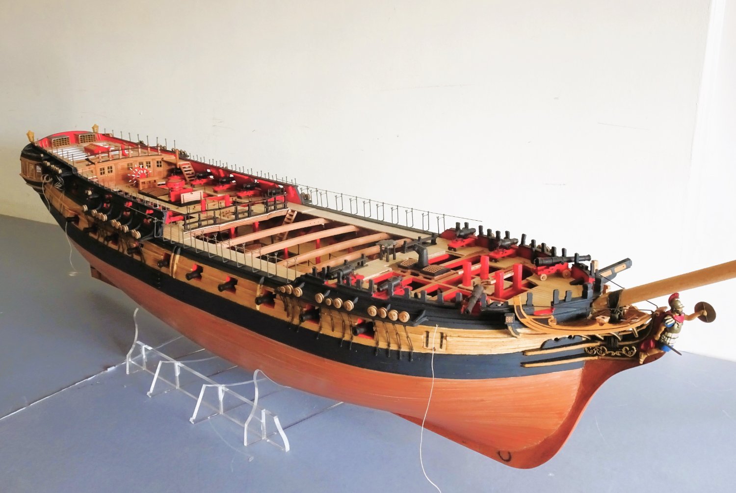
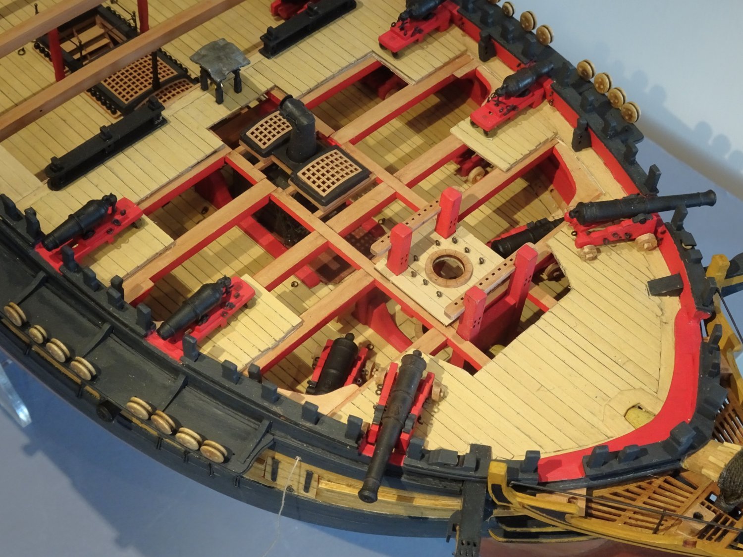
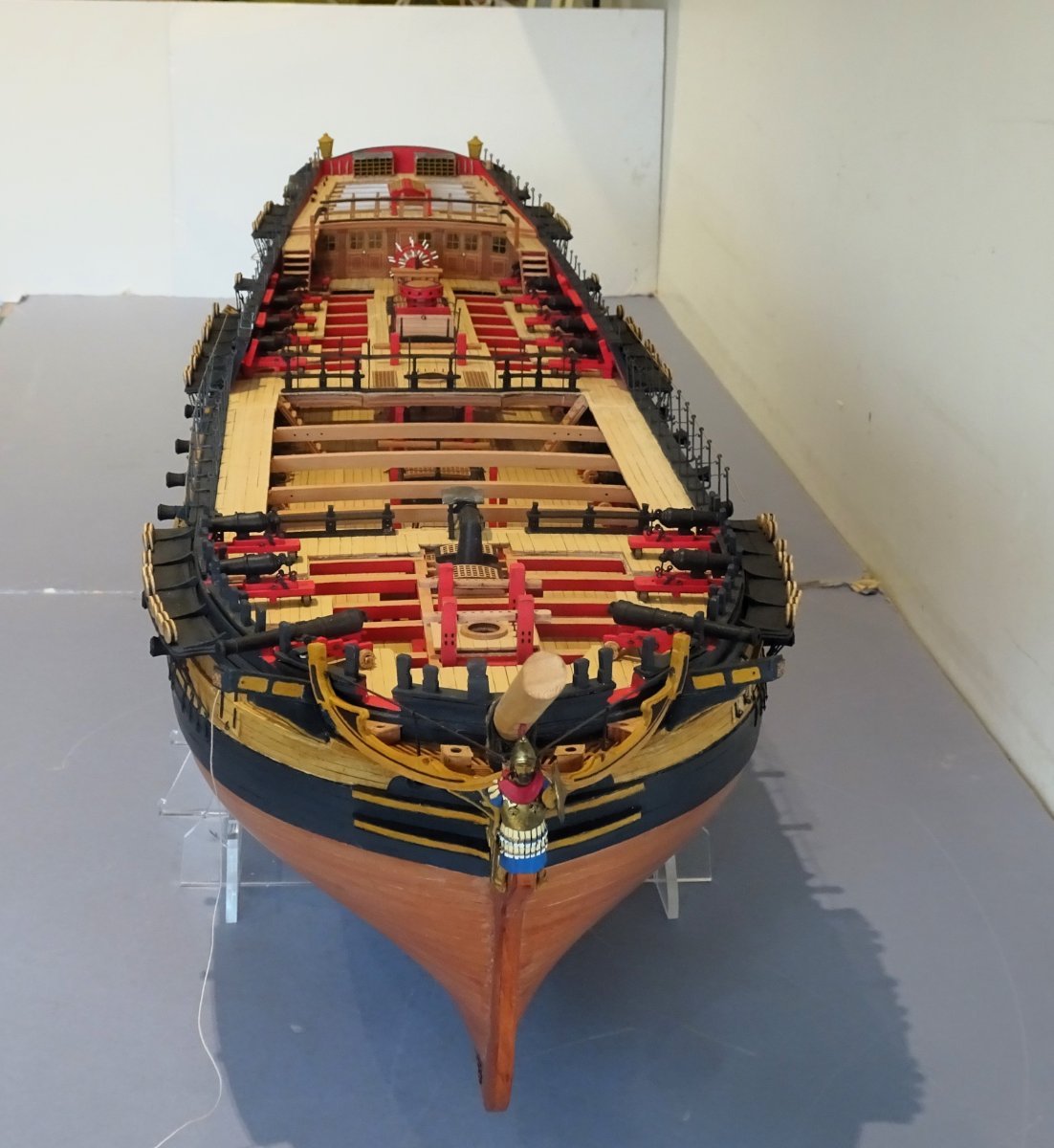
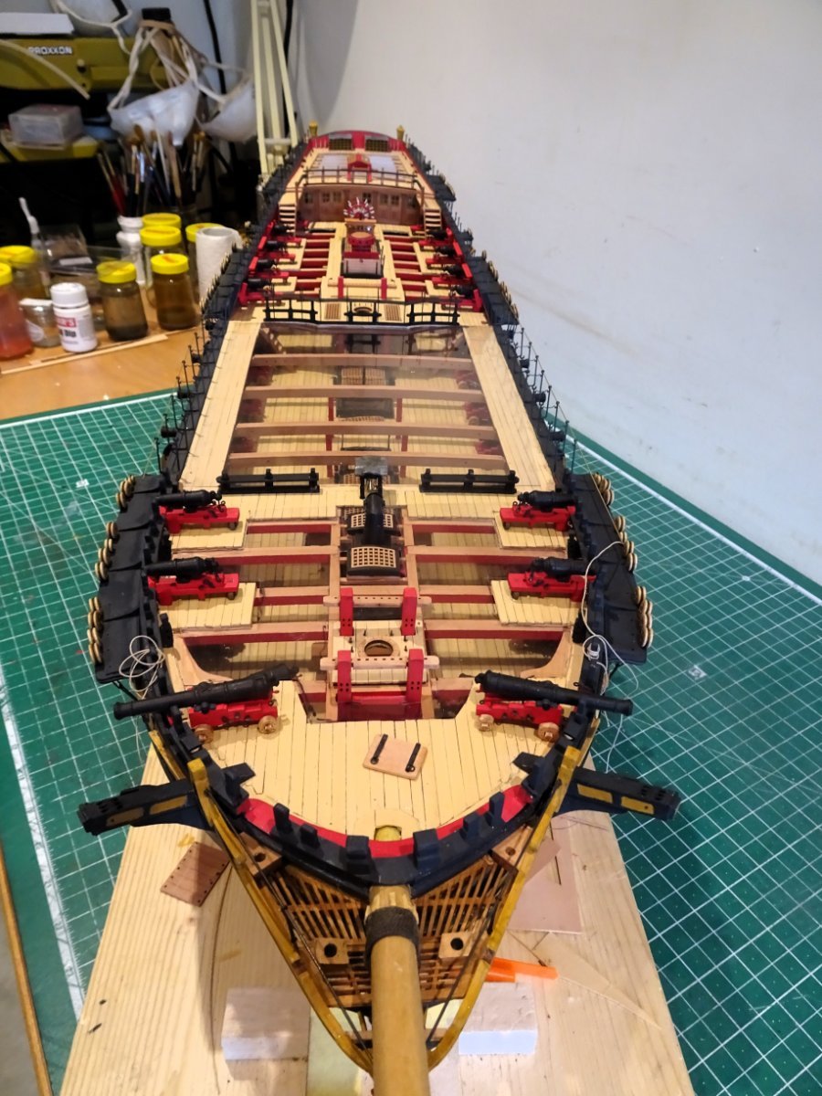
Apart from a few minor additions, the hull is effectively completed.
To mark the occasion, I cleaned up my workbench, and took some photo’s using my tripod rather than the usual handheld w-i-p shots.

3854

3899
3900
3901
3898
 3863
3863
3886
3876
 3878
3878
3889
3897

3895
3896
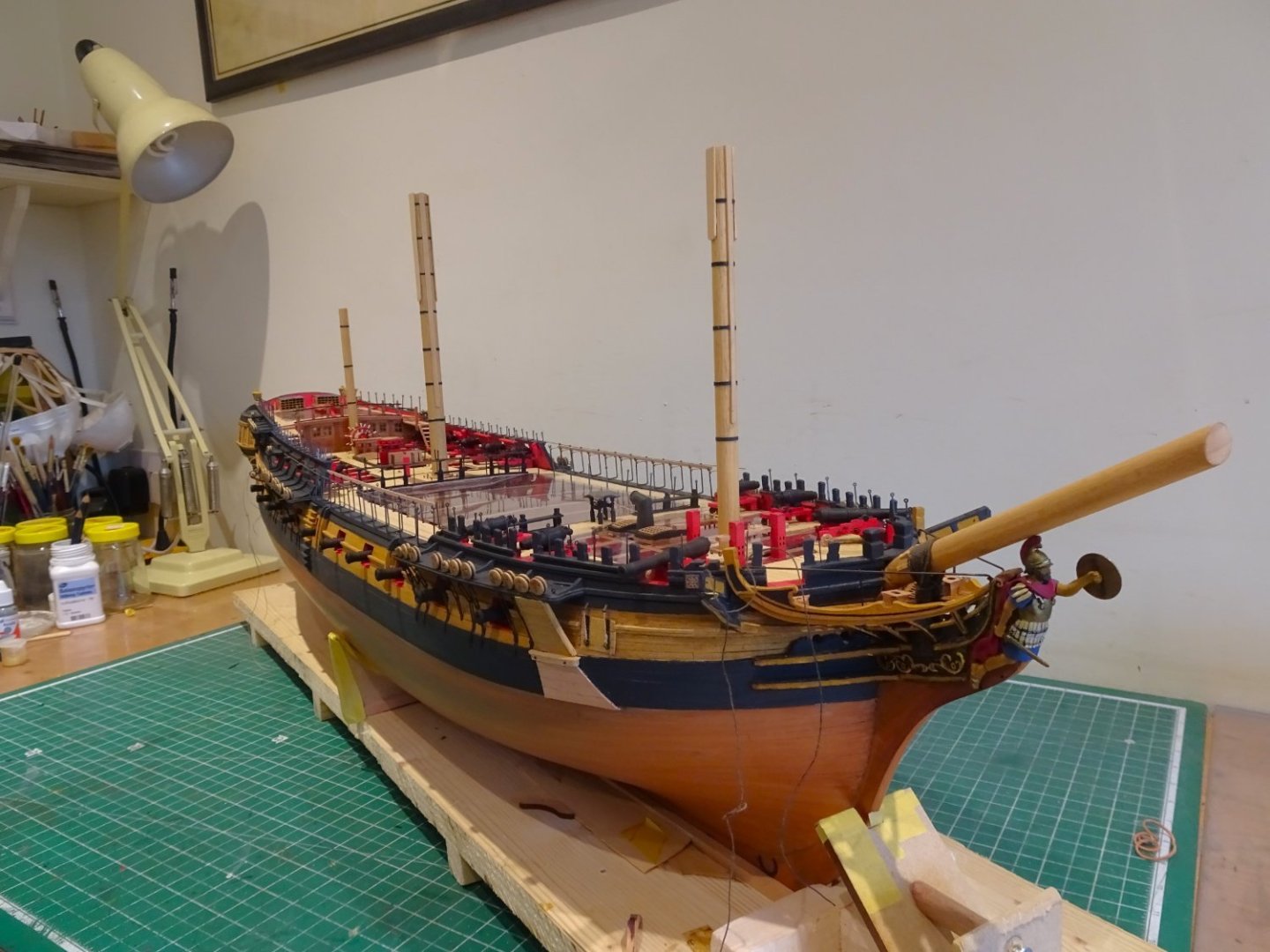
In the earlier stages of the build, I didn’t have the same sense of enjoyment I had with Sphinx, perhaps because it is a more difficult model to manoeuvre during building, it is large financial investment you don’t want to mess up, and it is a far testier challenge than Sphinx.
More recently, with the build challenges mostly behind me, I have warmed to the task, and there’s no denying the ‘Indy’ model certainly has that WOW factor.
Mrs W loves it, even if she is still asking where I’m going to put it.🫤
3905
Getting there Gov’nor, getting there.
Cheers Gromit.
B.E.
05/03/2024
-
Post One Hundred and Fifty-two
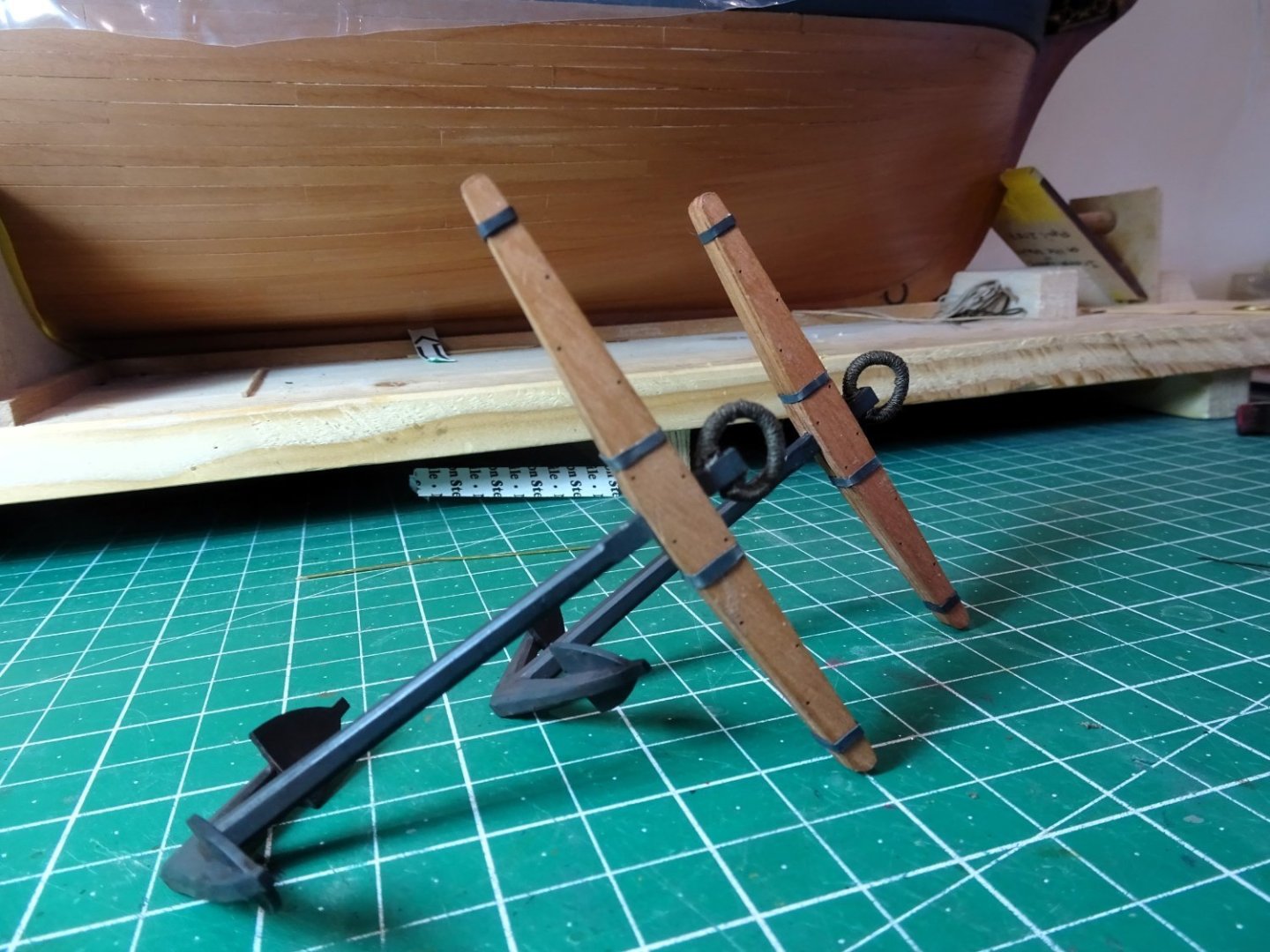
Anchors
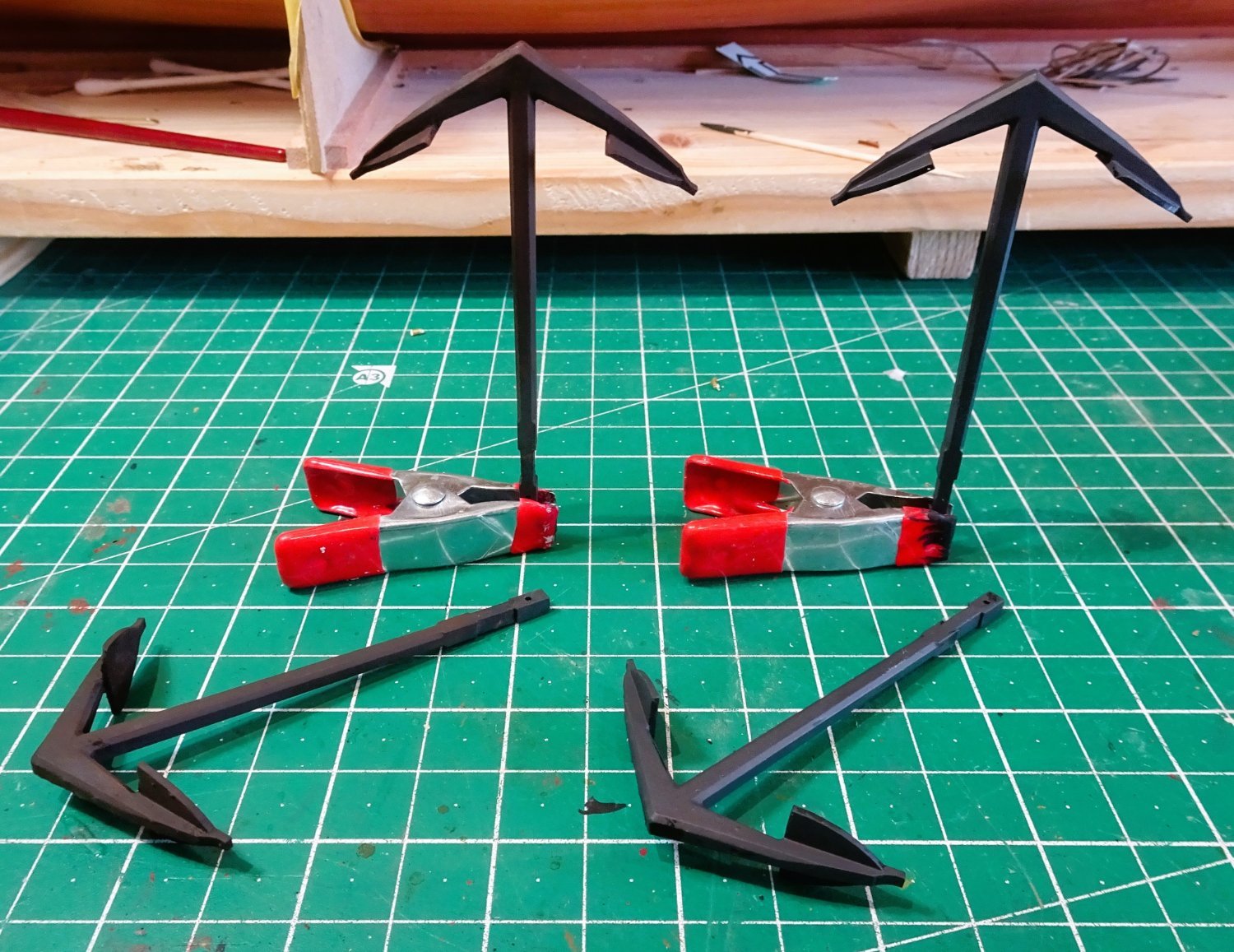
As a change of scene, I thought I would make up a couple of the anchors.
The kit includes the four main bower anchors, if the smaller stream and kedge anchors are required they are easily obtained using aftermarket suppliers.
The kit provided anchors have a scale shank length of 77mm (16’ 2”) which equates to a weight of 43cwt
This weight falls between the allocated anchor weights for 38-50-gun ships.
The outer diameter of the ring is 29” which scales to 11.5mm.
The thickness of the ring scales to 1.4mm.
A 64-gun ship had 4 bowers at 57cwt plus stream at 15cwt and a kedge of 7cwt 2qrts.
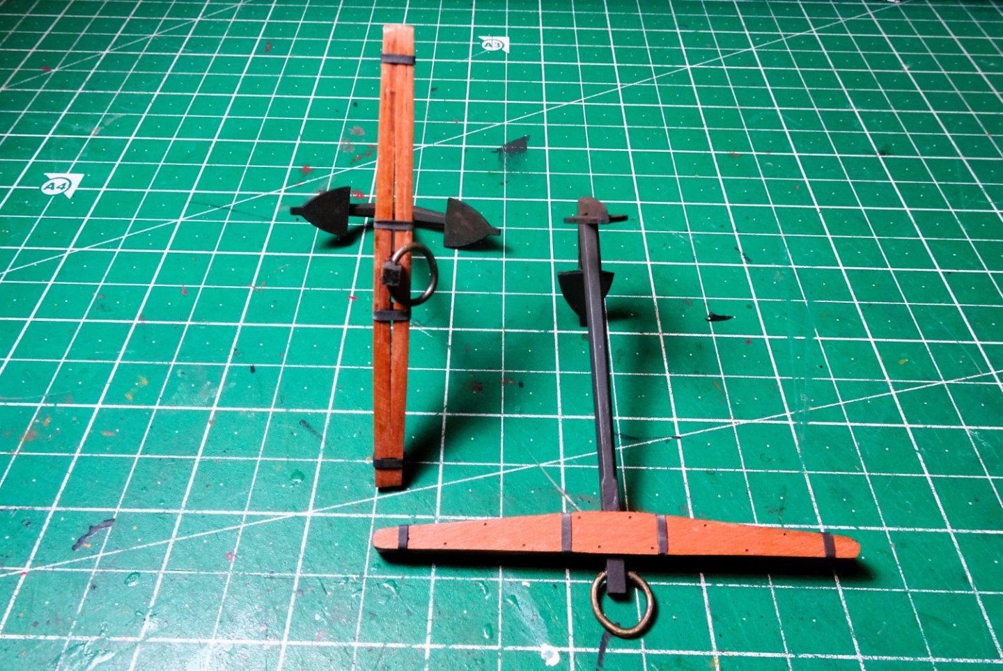
The kit anchors are 3d printed and very finely sculpted. All the subtle features are moulded into the shank and arms.
I think the day of the white metal anchor is coming to a close.
As with all resin stuff the parts need washing and priming.
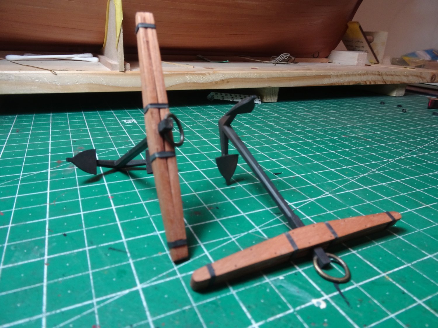
The stocks are pre-cut from Pearwood and are faced with a thinner veneer that contains the Trenails correctly positioned and with engraved markings for the iron retaining bands.

3831
The only modification I felt necessary was to taper the arms thickness a little from outside the central area towards the outer ends.
This reflects a more authentic shape.
Once primed, I used Vallejo black/grey, followed by dark brown /rust weathering powders.

3824
The anchors on the left have had the weathering treatment, those on the right as painted.
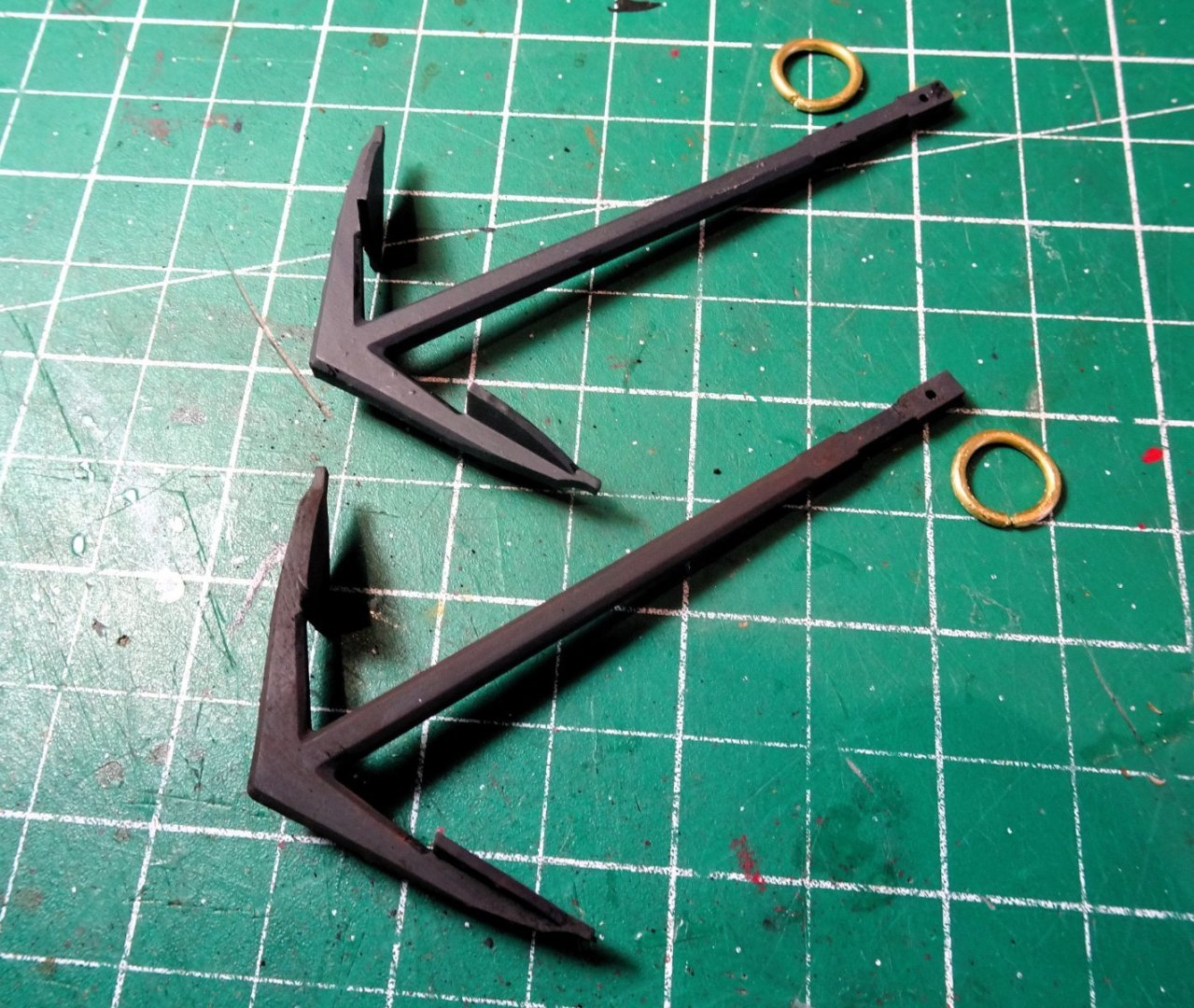
3830
Brass wire of 1.4mm ø was used to make the rings which have an outside ø of 11.5mm.

3835
The ends of the rings were reduced in size to fit the shank and chemically blackened to give a little tooth for the puddening.
The stock halves have mortises cut into the inner sides to fit against the shank. There should be a gap between them but I thought it a tad too large so I deepened the mortice somewhat.
Glued together the facings are then added.
3834
Those familiar with my stuff know that I favour heat shrink rubber tubing to represent iron hoops.
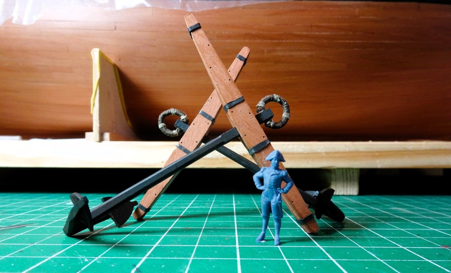
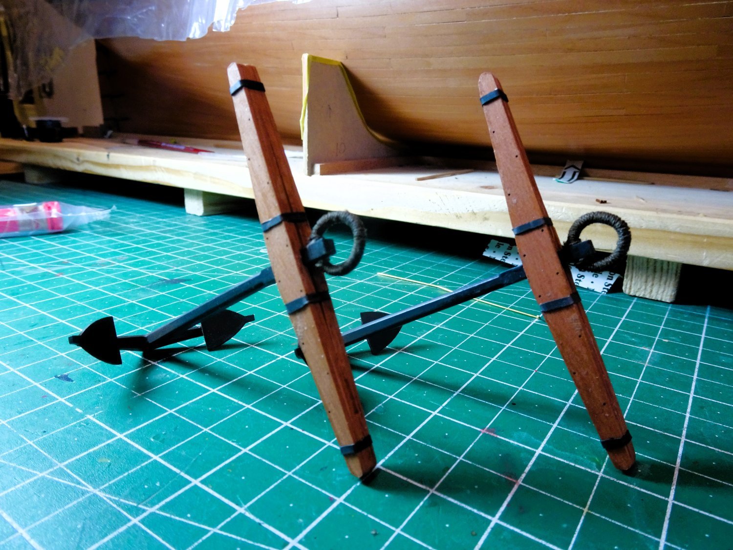
The final part is to add the puddening to the anchor ring.
I used Syren 0.45mm ø and Morope 0.1mm stuff for the seizings.
3838
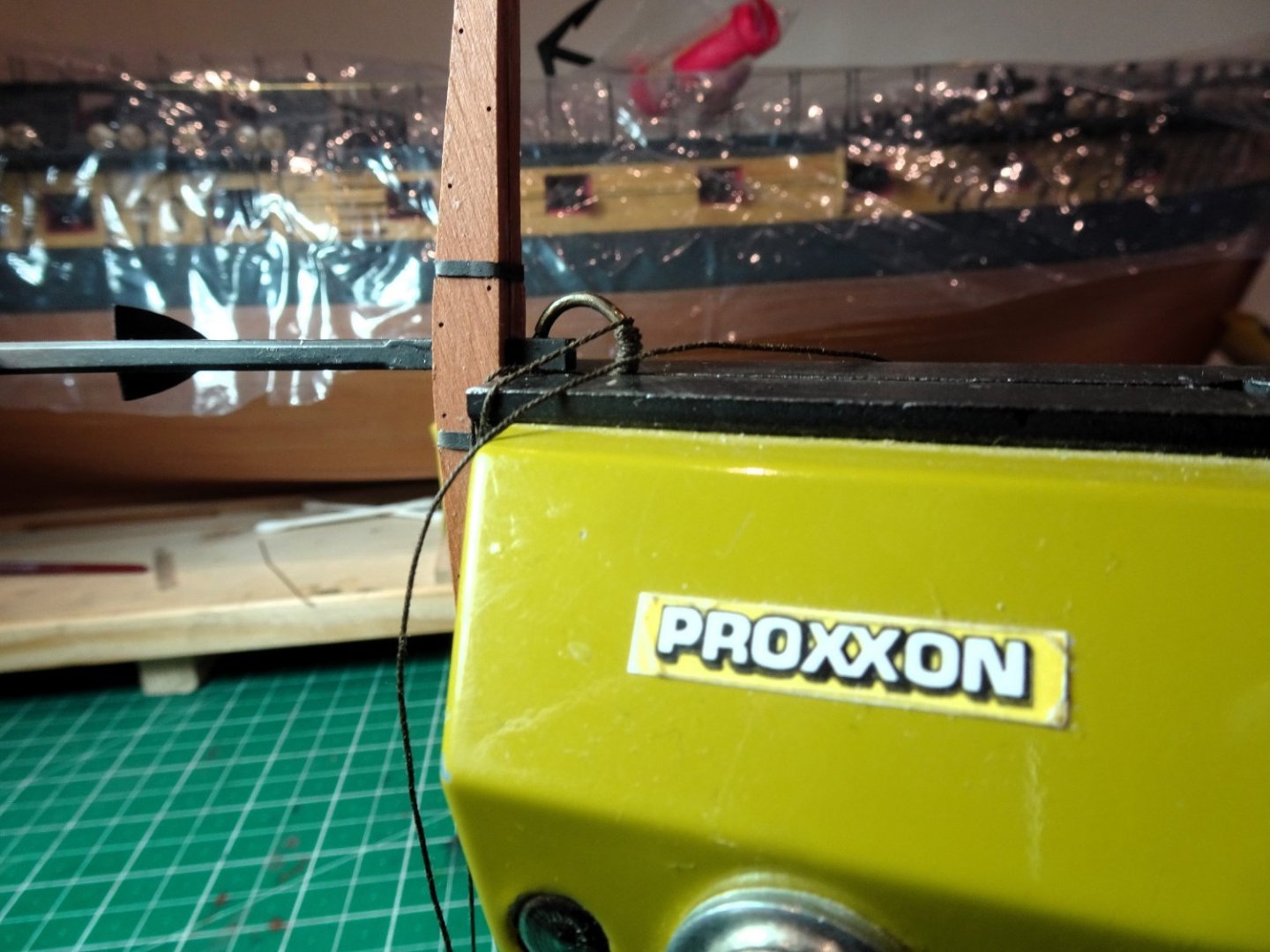
In applying the puddening unless you glue the ring in place it needs to be held steady. As I work around the ring I apply pva to help keep it in place.
3842

3847
3849
Capt. Pellew is dwarfed by Indy’s anchors.
I won’t be fitting or rigging the anchors but as far as I can see there is no reference to this in either manual or plans, so other sources will have to be found; fortunately there are many available.
B.E.
02/03/2024
- Thukydides, mtaylor, KARAVOKIRIS and 22 others
-
25
-
Neat work on the Mizen Stay Glenn,
You know you can improve the look of the mouses on the stay collars immensely simply by using formed styrene tubing or wooden dowel covered with material from a pair of your wife's old tights, but don't let her catch you cutting them up.😉
B.E.
-
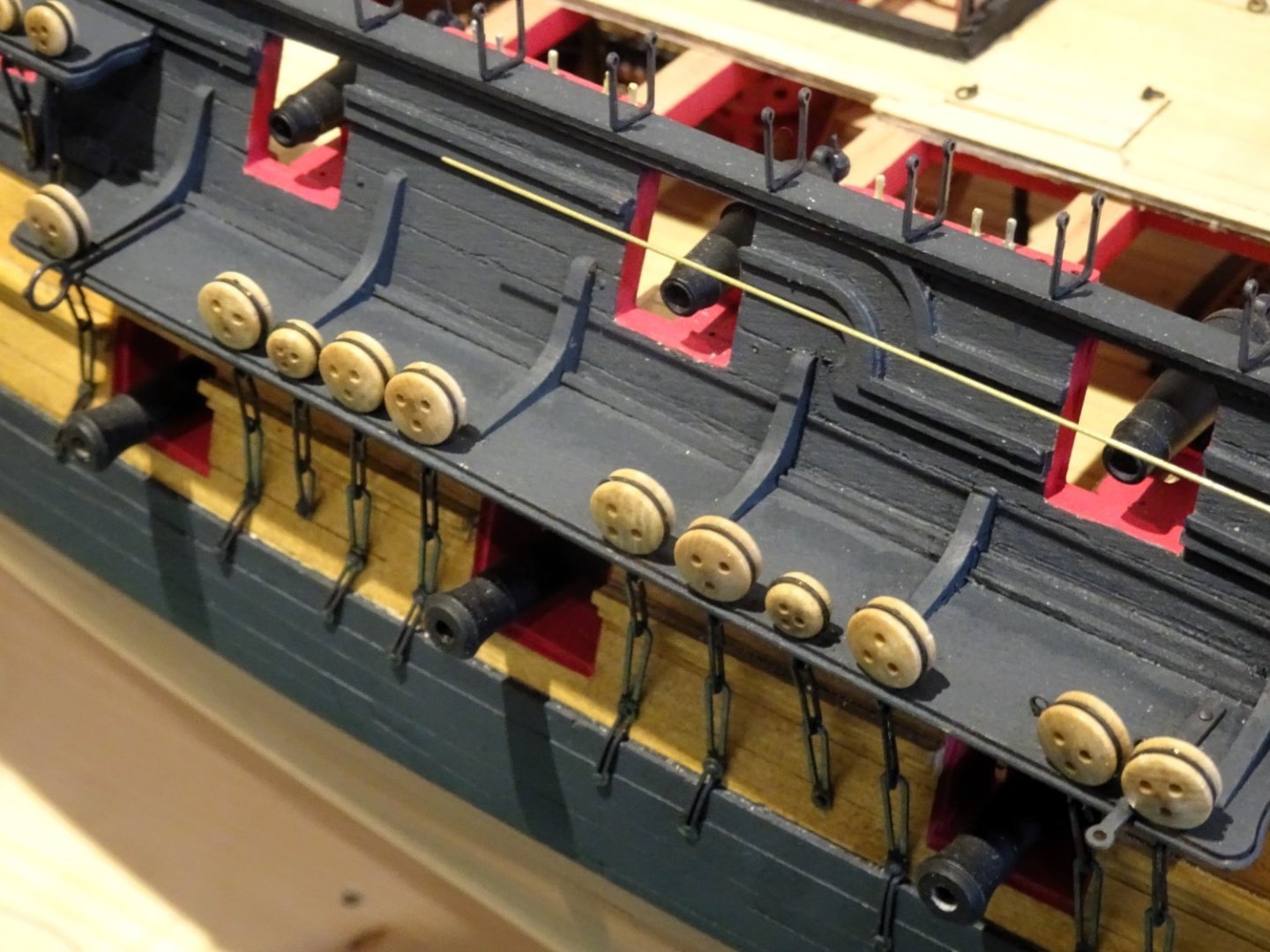
Post One Hundred and fifty-one
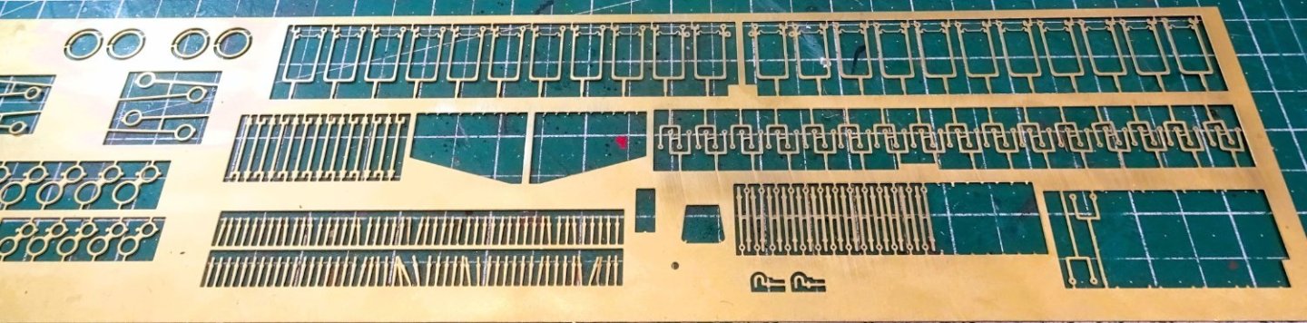
All things brass
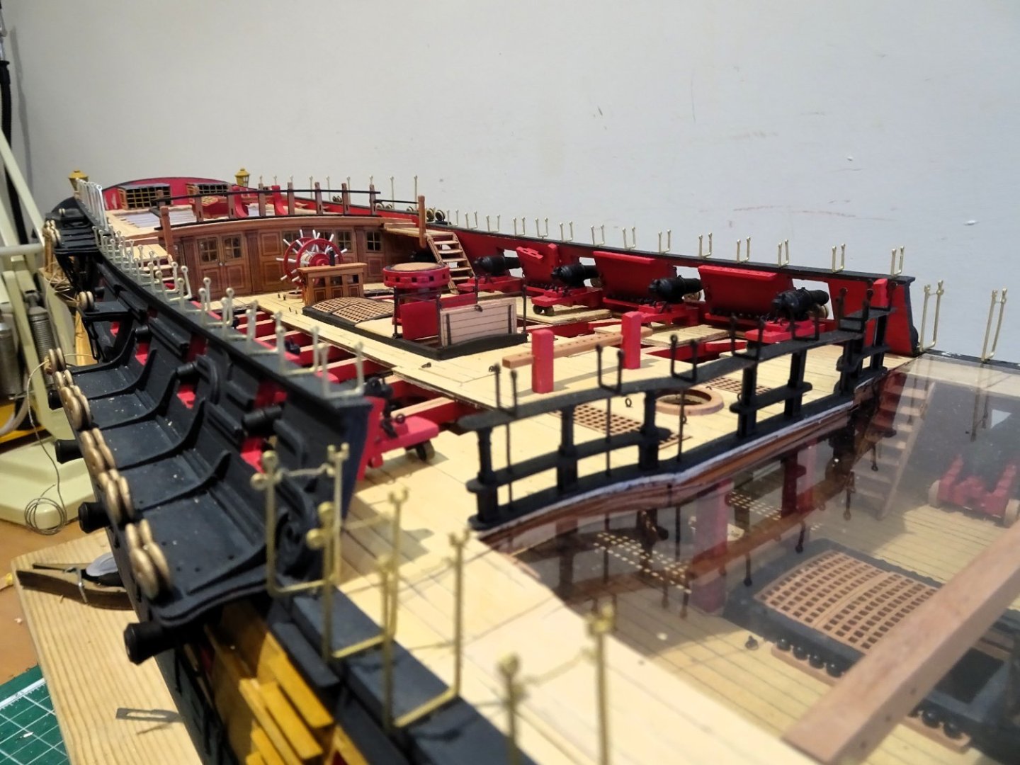
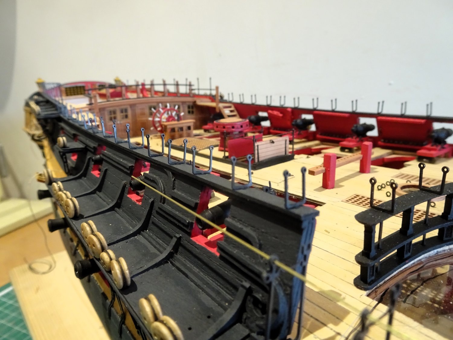
A few days taken up with the fitting of deck eyebolts, stanchions, and hammock cranes.
 3810
3810
These items are beautifully crafted by Chris particularly the waist cranes with integral retaining hooks and eyes.
Cranes also line the Qtr deck bulwark and are placed atop the Qtr deck breast rail.
Before removal from the fret I clean with fine steel wool which aids the subsequent blackening process.
3813
Once removed the Qtr deck cranes needed careful cleaning up to remove all traces of the fret nubs and are then trial fitted to reduce handling later.
They are given an acid bath, followed by the blackening procedure.

3818
3819

3814
I use 0.5mm ø brass tubing to maintain the line whilst progressively fitting the waist cranes.
3815

3816

3817

3823
I did notice that cranes or stanchions are not provided for the Fo’csle rails between the timberheads.
Should there be, I don’t know. 🤔
Victory was equipped with cranes, and the Sphinx model has stanchions around the Fo’csle.
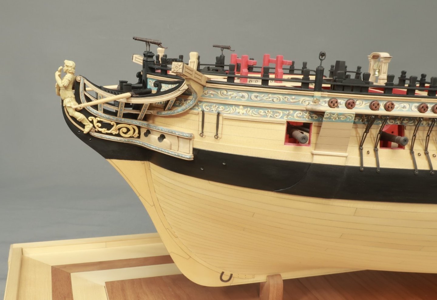
The contemporary model of Amazon (32) 1773 had stanchions around the Fo’csle between the timberheads.
I am inclined to think that 'Indy' may have had them for safety on the exposed Foc’sle, particularly as we know these razees were prone greater rolling.
I’ll have a ferret thro’ my spares box and see how they look.
B.E.
29/02/2024
- scrubbyj427, chris watton, davyboy and 29 others
-
27
-
 5
5


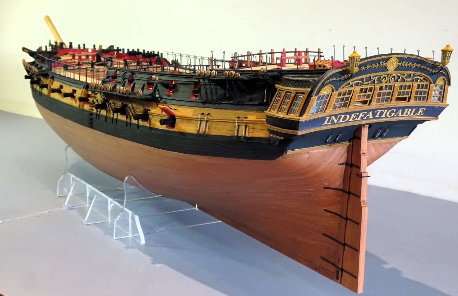
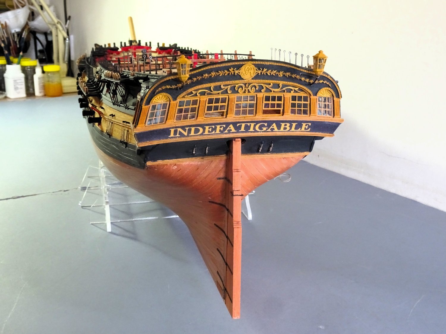


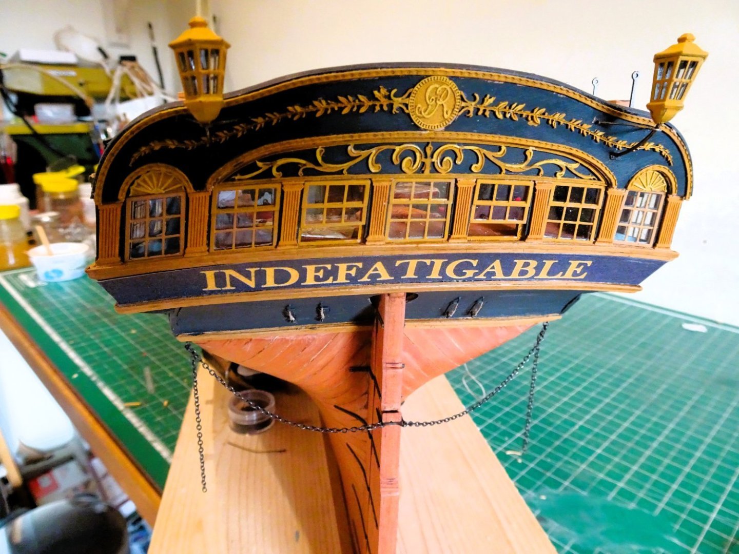
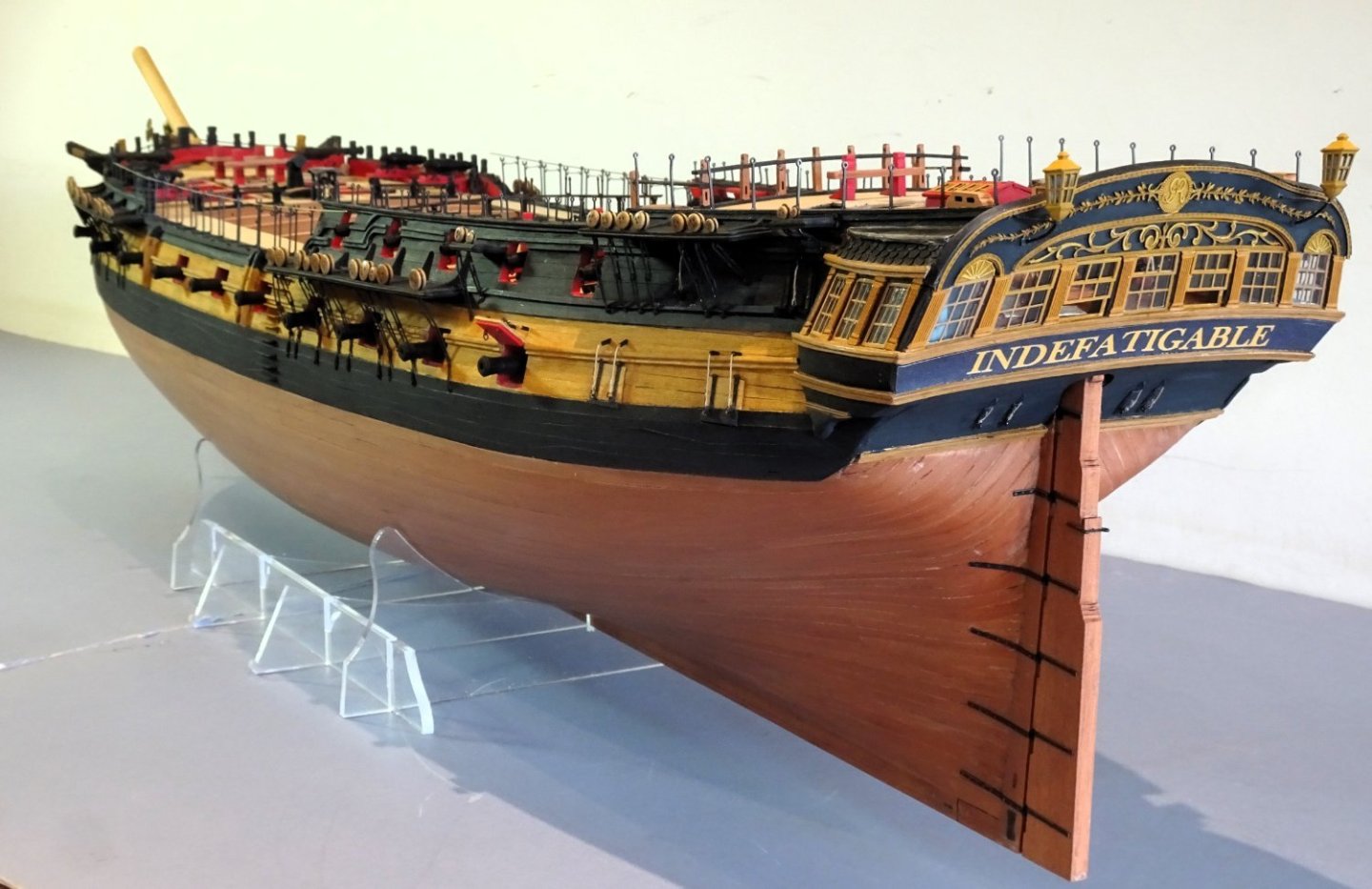
HMS Indefatigable 1794 by Blue Ensign - FINISHED - Vanguard Models - 1:64 scale
in - Kit build logs for subjects built from 1751 - 1800
Posted
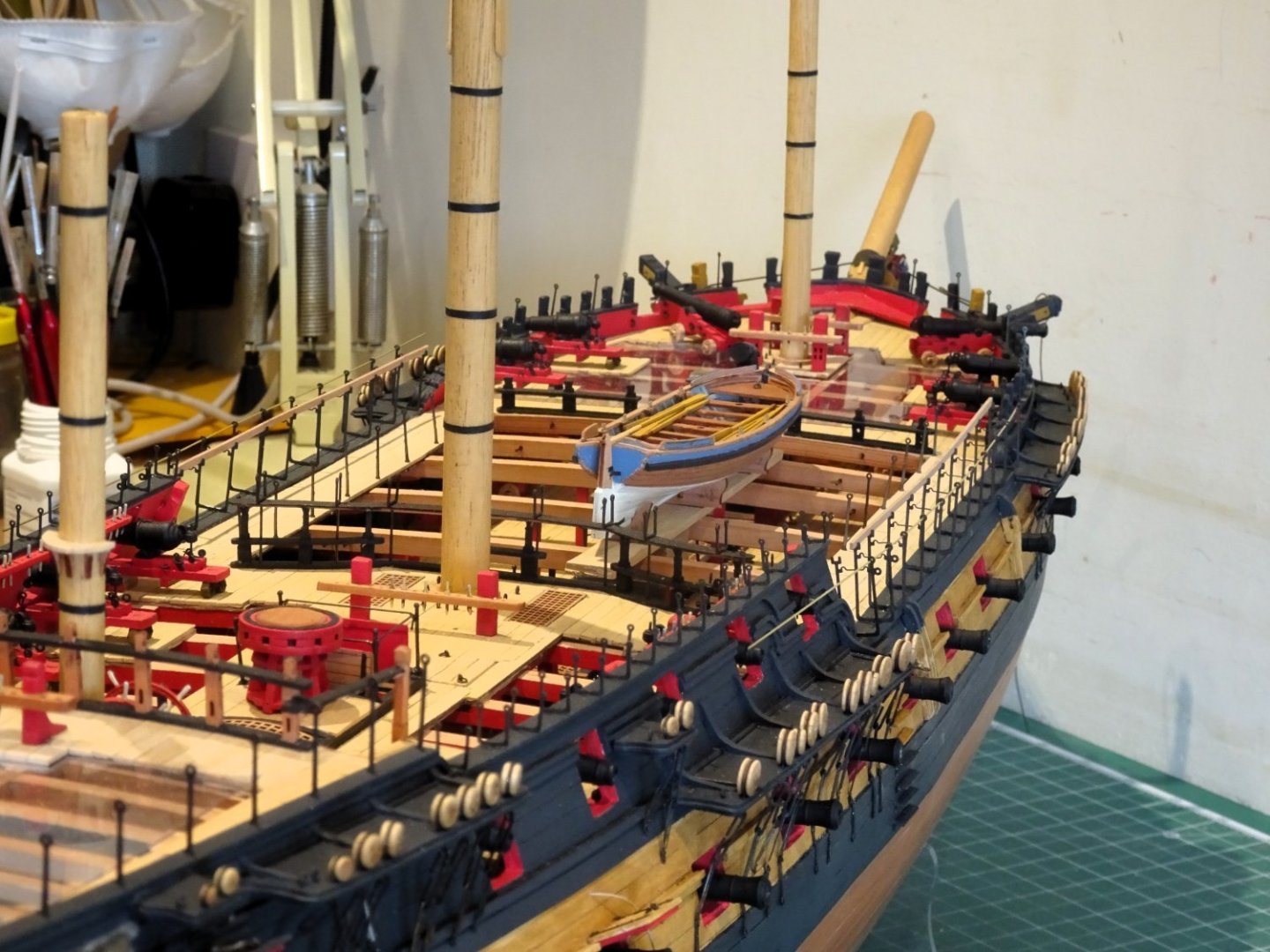
Post One Hundred and Sixty-two.
Woolding the masts
The kit indicates use of 0.5mmø line throughout.
According to Steel the wooldings for the Fore and Mainmasts are of 3” circ line, and that for the Mizen 2½” circ.
This equates to 0.37mm and 0.31mm scale diameters.
I used 0.3mm and 0.4mm cotton line from Modellbau Takelgarn in Germany.
Wooldings are generally 12” deep which scales to 4.76mm.
The method of applying as shown on the kit plans is the recognised approach to take, and will be familiar to readers of R.C. Anderson’s wordy but excellent book The Rigging of Ships in the days of the Spritsail Topmast 1600-1720
I wouldn’t be without it.
4132
4133
The line was dyed using Colron Jacobean Dark Oak wood dye which gives a less black effect than commercial black rigging line.
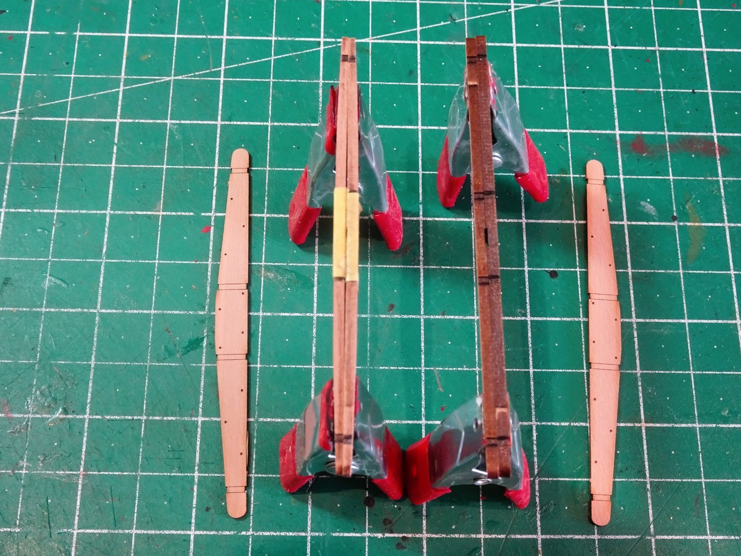
The final touch is adding the wooden hoops that contain the woolding.
4140
These are simply made using very thin strips cut from a Manilla folder.
4137
4138
4148
Nearly there! and with great timing the the display case arrived yesterday.
B.E.
28/03/2024.