testazyk
-
Posts
337 -
Joined
-
Last visited
Content Type
Profiles
Forums
Gallery
Events
Everything posted by testazyk
-
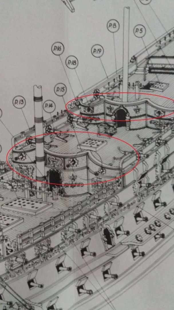
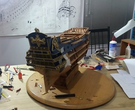
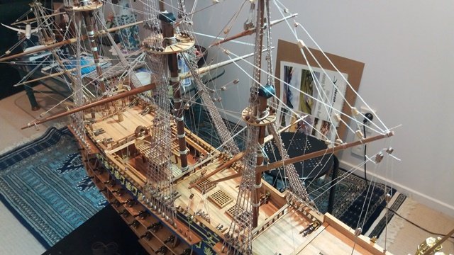
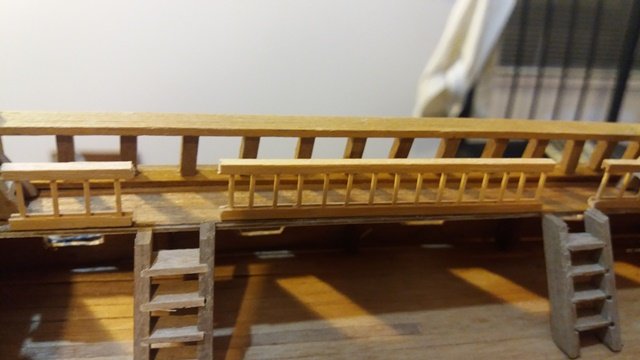
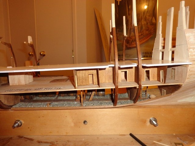
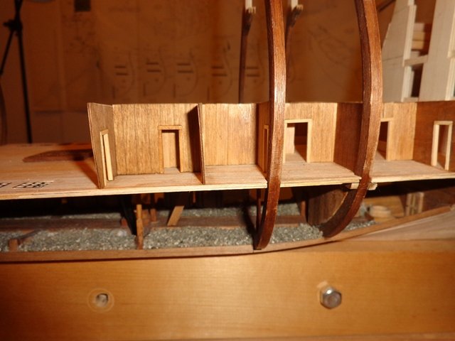
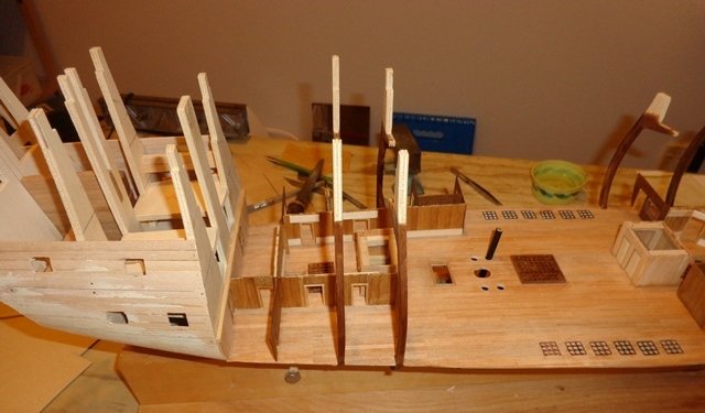
 Hi all, I'm working on the 80's vintage Mantua Sergal Sovereign of the Seas and in those days they gave you no help--not even laser cutting! I'm about to put top rails on the scalloped bulkheads and wanted to hear anyone's thoughts on the best approach. In newer kits they give you precut pieces. Ideally, I'd build them up out of 2x6 walnut strips but because the curves are so extreme I can't envision how to do with with scarfs. Plan B is to trace them from the actual ship and cut them out of ply and sand them to shape. Any suggestions or guidance would be most welcome. Attached are some pics to give you an idea of what I am describing. Thanks!
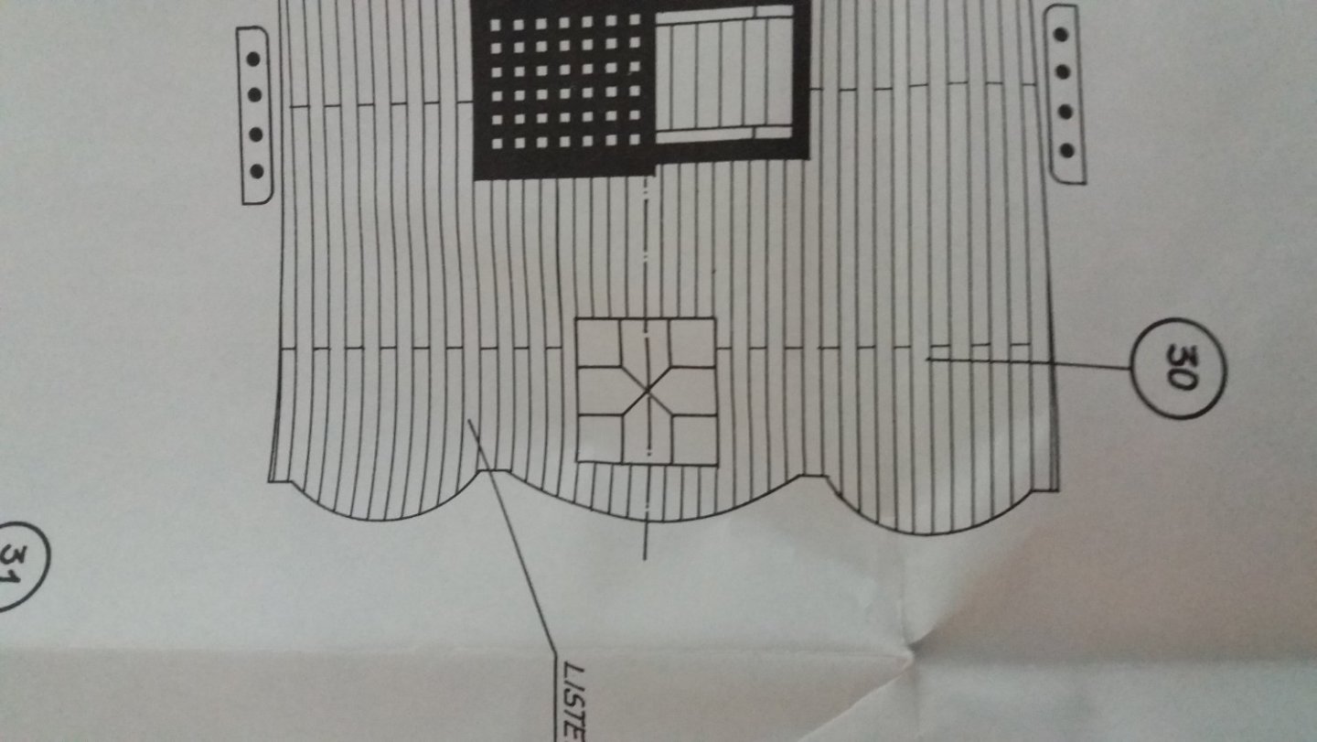
-
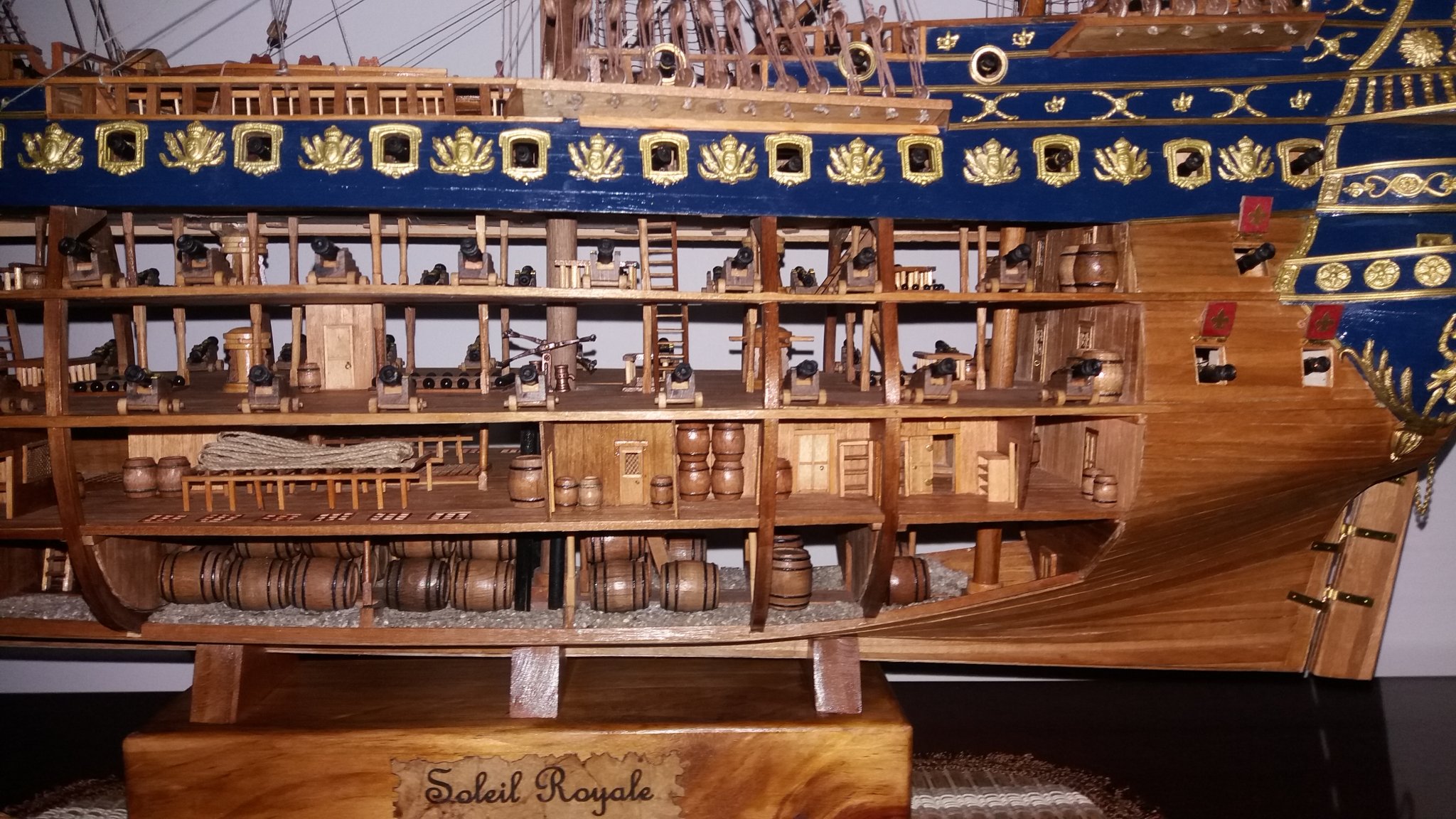
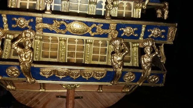
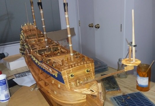
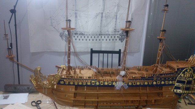
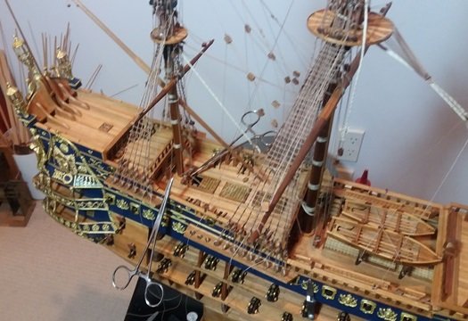
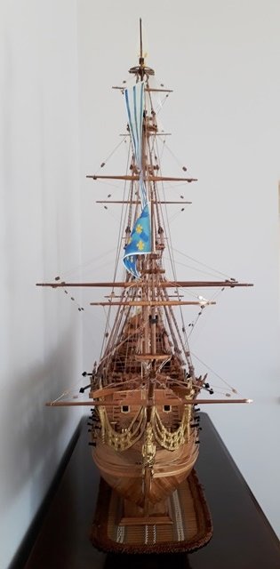
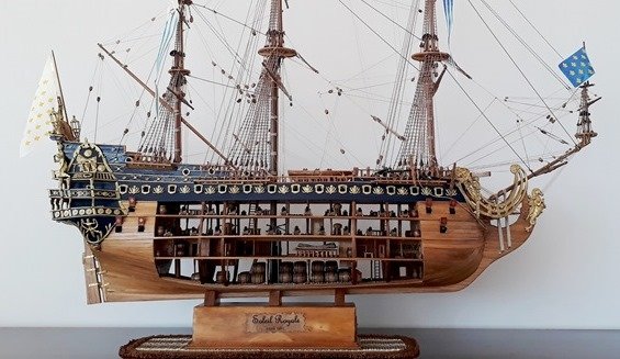
With the ship securely mounted, it was time to attach the decorative brass. I don't want to continue to talk down the quality of the kit, but the brass castings are actually quite poor. I spent hours sanding and filing off rough spots and trying to fix imperfections and then painted each piece with gold enamel. had previously sanded off any rough spots or imperfections and painted each piece with gold enamel. As far s advice on placing the pieces, in retrospect it all made sense, but I found it very hard to visualize from the plans exactly where some of the different pieces were supposed to go. In the end I accounted for each piece, figured out a logical place and put it down. I was surprised to have a few extra of some pieces so I added them in where it made sense. If you are building this kit and have a question, let me know and I can try to answer or send you a picture that might help. I don't know about you, but attaching metal bits to wood has always been a challenge. Epoxy is the best, but it's difficult to work with and easy to waste when doing a job like attaching little pieces that have to be filed to size as you go. On my last build I found some red thread locker which worked perfectly, but I can't find that brand and all the other (I tried three different ones) don't work. So the next choice is cyano glue, but I have a really bad allergy to it. I did some research and found something called Zap O Foam Odorless CA. It really is odorless and slighty less aggravating from an allergy perspective. It isn't as instant a bond as regular CA, but still very effective. With the decorative work finished, I was in the home stretch with the masts and rigging being the last big tasks. A lot has been written about how bad the rigging scheme is for this kit and there is a lot wrong with it on many levels. I decided to go with the basic scheme but I did replace some of the blocks which were grossly oversized. For rigging line, rather than use what came with the kit, I sourced light brown line in 3 sizes from Syren. I used .045 for the shrouds, .035 for the stays and .012 for the running rigging and reeving and rattling the shrouds. To take a break from knot tying, I installed the guns. As usual, during the running rigging work, everything looked like a big mess until the lines were all secured. And here are some pictures of the finished ship-- I hope you enjoyed this log. If you would like more information or to see more pictures, please see https://testazyk.com/2020/05/23/soleil-royal/ Thank you for all of your feedback and support!


- 15 replies
-
- 2
-

-
- mantua
- soleil royal
- (and 2 more)
-
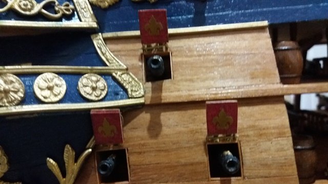
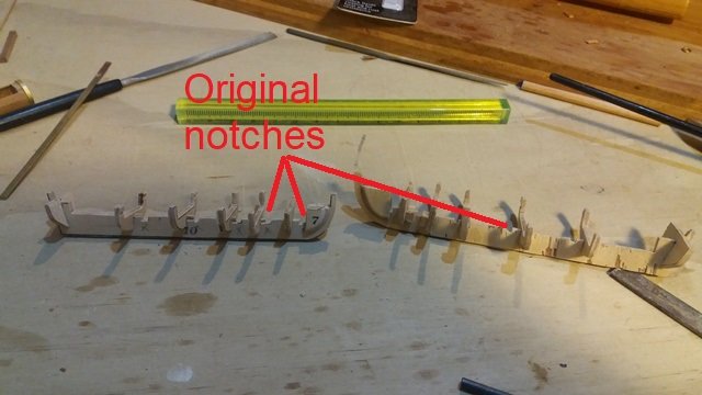
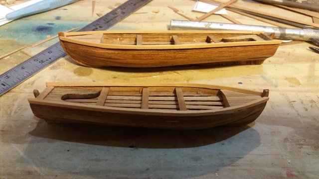
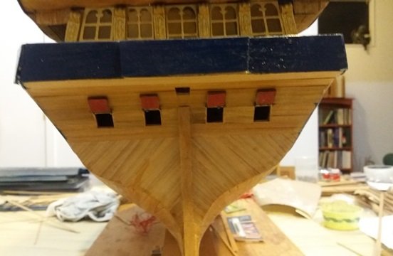
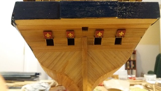
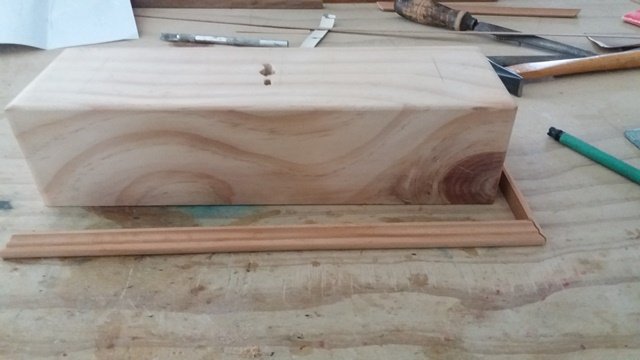
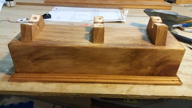
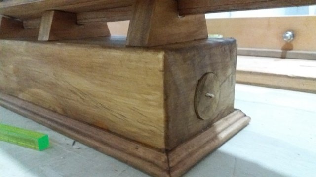
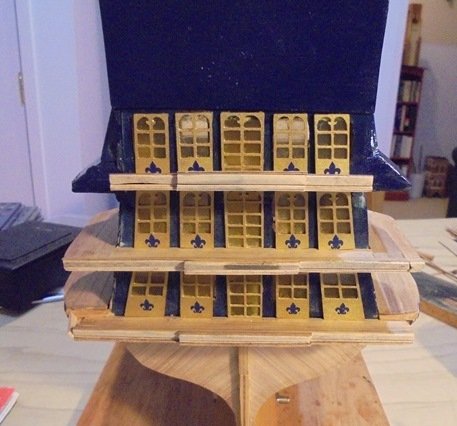
The next task was one of the biggest challenges—building the boats. This time I took a long look at the materials supplied in the kit and decided that they needed to be re-engineered in order for the boats to look at all decent. The kit provides keels and ribs but the issue is that the notches for the ribs are positioned too far forward. As a result, the planks at the bow will have an extreme curve and the boats will look like blunt nosed cucumbers. I repositioned all of the ribs to make the curves more realistic. It was time to finish off the stern and install the gun port lids. I got some gold stick on fleur de lis and added them for additional decoration. I added a few more pillars and other details to gun decks. It was now time to tackle another challenging task—the stand for the ship. Usually the stand is a fairly straightforward project but this time I had the additional challenges of concealing the power supply for the lights and also providing additional height so that it would be easier to see the lower decks where most of the detail is. I drew up a few designs involving drawers and sliding doors but finally decided to go with a simple solid block with a hollow to contain the batteries and switch. The wiring exits the bottom of the ship and threads through the middle support bracket. The batteries and switch are accessed through the round door. I want to thank my friend Alan for providing the block and for drilling the hole with his professional drill press. There was another breathless moment as the lighting was tested to make sure all the connections had survived. The next step was to tackle the brass decorations.
- 15 replies
-
- 1
-
-
- mantua
- soleil royal
- (and 2 more)
-
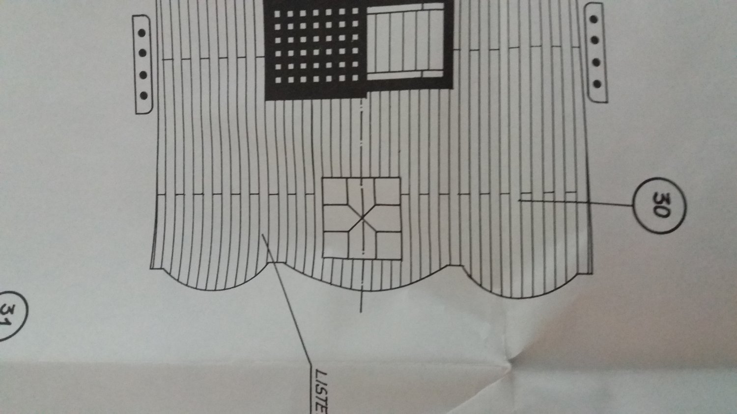
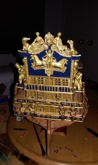
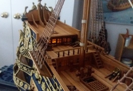
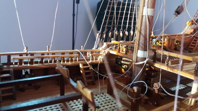
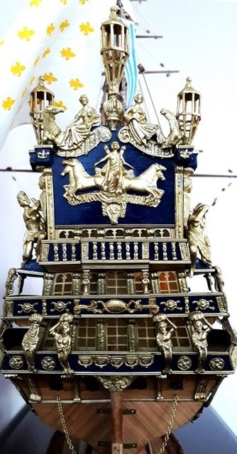
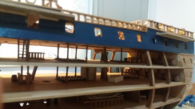
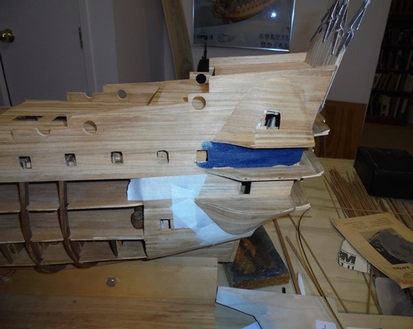
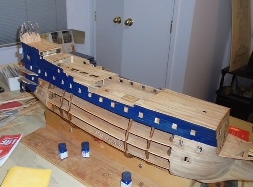
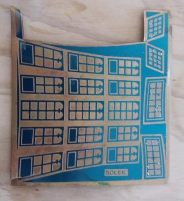
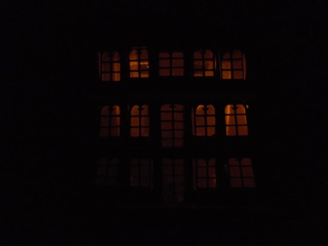
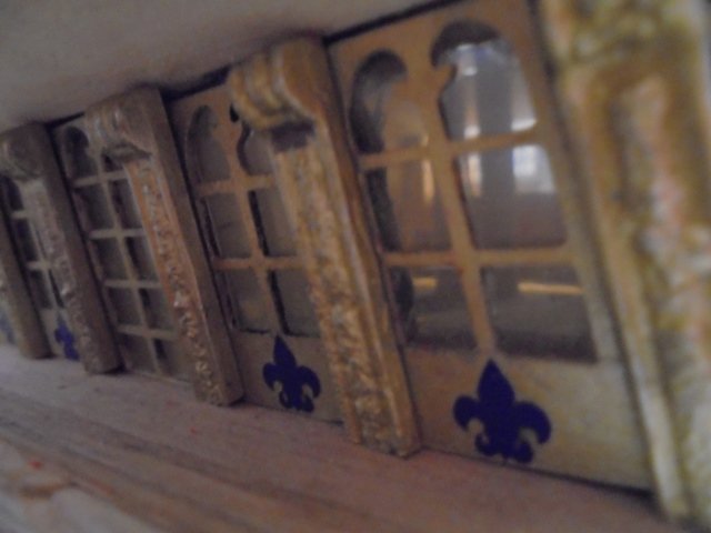
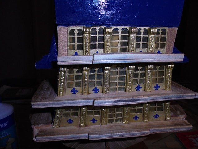
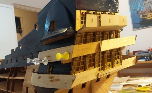
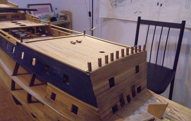
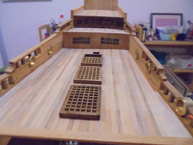
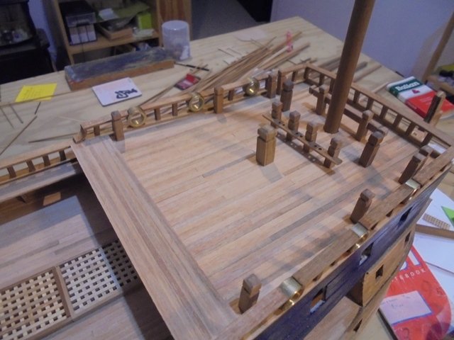
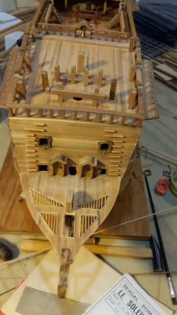
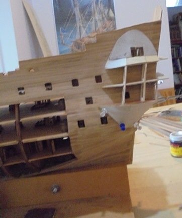
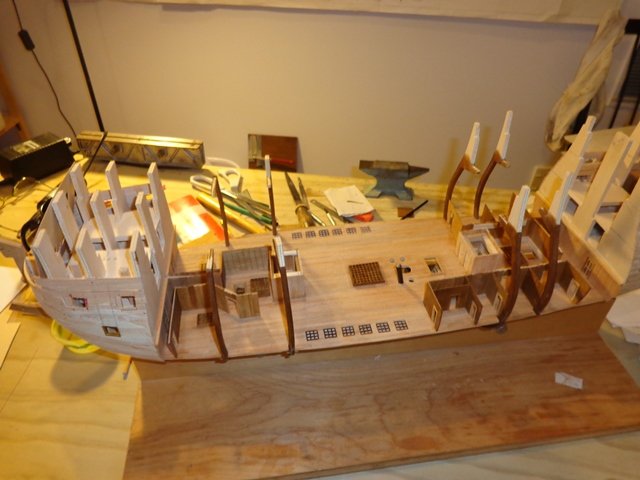
It was then time for another deep breath--painting can't be undone and it was time to paint the bulwark and gallery areas. The kit suggests a light blue, but for the Royal Sun, I decided to use ‘royal blue.’ The point of the paint is to help the gold decorative work show up so a darker colour made more sense. I masked off the area and went to work. Now was the time to tackle the stern. The first step was planking. The stern of the ship has three levels of windows and doors and as usual, the kit provided stamped metal sheets. The idea is that you cut paint the windows blue or gray to look like glass reflecting sky and water and when you rub off the excess you are left with a brass outline. That usually isn’t a bad look although it’s hardly realistic. Because the stern of the ship is so ornate and because I was installing lights, I wanted something different. Cutting out the little windows was out of the question but I found a local company who does laser cutting. I gave them a thin square of plywood and an outline of the windows on the sheet and they cut them out beautifully. I then used thin yellow plastic to simulate the horn that the windows would have been made of at that time. I’m really happy with the result: I know it will horrify the sensitivities of any purists, but in order to dress things up a bit I added the blue fleur de lys to each window. I found them on a web site selling stick on fingernail decorations! Here is a view from the main deck: And with the lights on: And this is after I added some of the brass decorations: The next step was to install the solid railings around the galleries. I used the ply supplied in the kit for the straight rails in back, but in order to get the bends in the port and starboard rails I again used the superthin ply I'd used for the raised sections above and below the railings. After making sure everything fit and was at the right angle I painted the railings. Before installing the brass decorations, I decided to do the work on the decks, staring with the railings. If you are building the ship, don't forget to leave extra space for the cat davits in the forward railing posts. I also added the bits and fife rails. According to the plans, there are no railings on the walkways connecting the quarter deck and the fo’c’sle, but I thought they would look good (and the sailors would appreciate them). And then finished off the bow work. Don't install the heads until after you've attached the brass railings to make sure they don't get in the way.
- 15 replies
-
- 1
-
-
- mantua
- soleil royal
- (and 2 more)
-
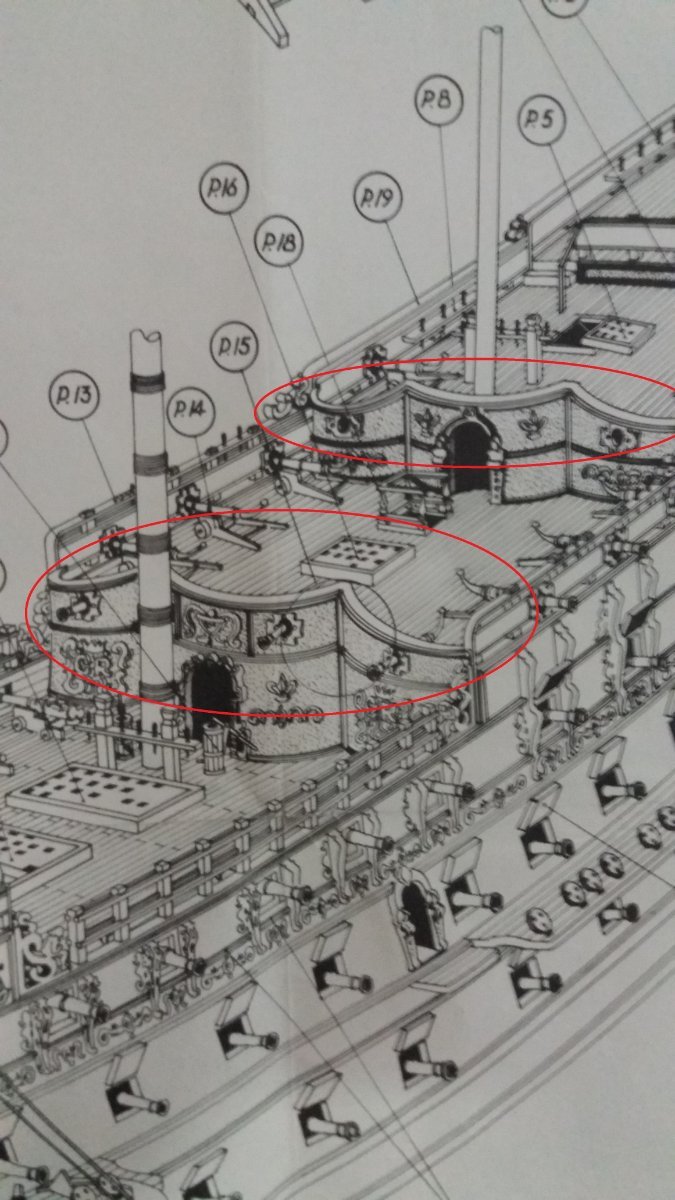
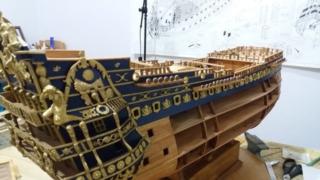
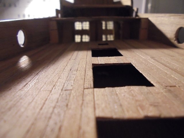
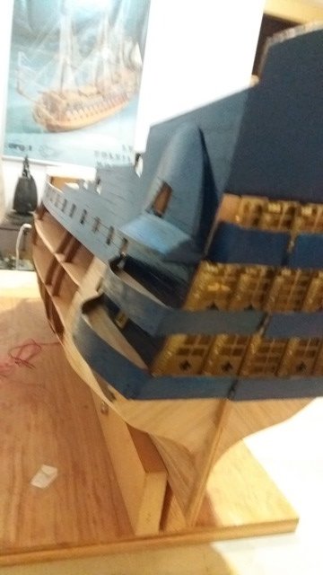
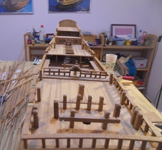
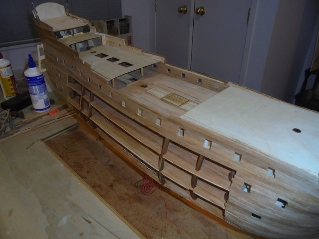
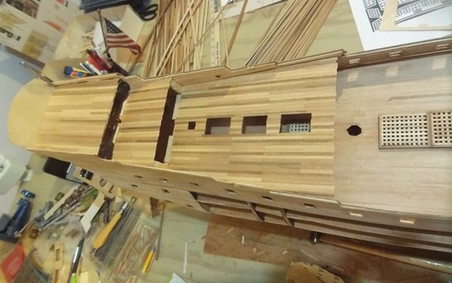
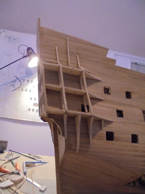
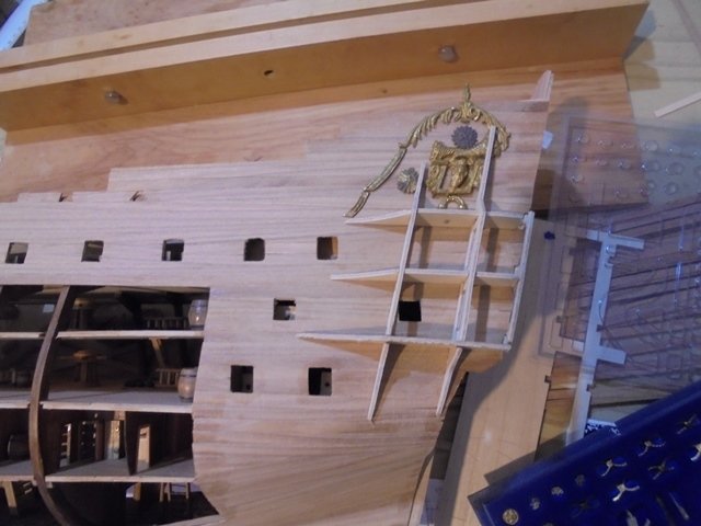
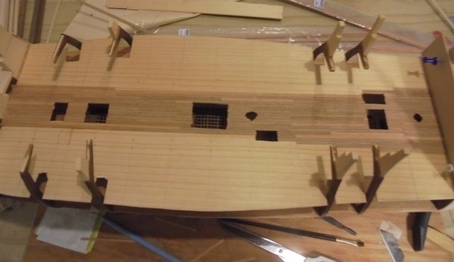
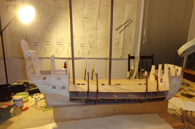
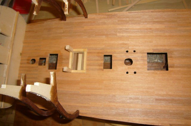
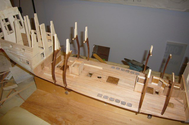
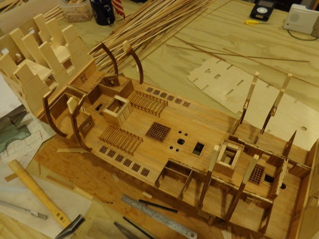
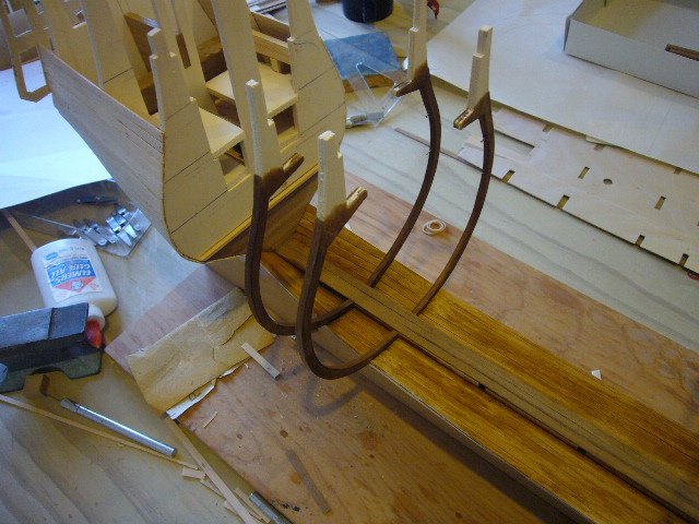
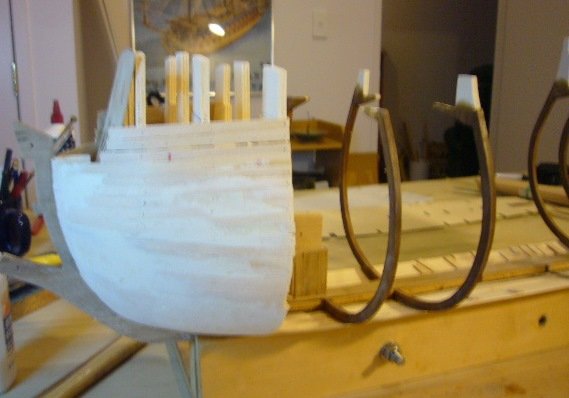
The first step was to install the upper deck which had been provided in the kit. I’d used the side frames which had supports for the deck and the upper bulwarks. And I could get an idea of how the finished ship might look! I planked the upper deck and installed grates, and then installed the quarter deck, fo’c’sle and poop decks. If you are planning to do this kit, be sure to take some time to study the deck arrangement and spacing and to fair the tops of the frames. Also, check the layout of the various guns to make sure everything fits and is aligned properly. You can see an issue with the angle of the deck above the quarter deck--it required a lot of adjustment. And built up the bulwarks. I overbuilt them because the plans are inconsistent about placement of railings. They also do not reflect reality as far as the spacing of decks, gunports, etc. so be sure to take extra time to plan everything and make sure the poop deck is angled properly and you have enough room for the circular gun ports. Then came the interesting challenge of cutting out the upper deck gunports. You have to be careful here because under the focsle some of the guns are placed in pegs and in the waist they are on carriages. If you aren't careful, you will have a gun where the bulkhead of the focsle is supposed to be. Also, the plans don't tell you to install blocks for the dummy guns under the focsle, so be sure to plan ahead for that. Also, if you are going to use the brass gunport rims that come with the ship, be sure to check each one--they aren't consistently sized or shaped. I ended up custom shaping each hole and then numbering them to the port rim that fit that particular hole. Also, the rims have a flange to fit into the hole in the bulkhead and those aren't always consistent so that the rims won't be at the same angle. It's easier to shape the hole in the bulkhead than to file the metal square. The top decks were planked: And it was time to put on the second layer of planking. Next came a series of interesting challenges. The stern of the Soleiel Royal has big wraparound galleries and also an unusual raised area under the side galleries. The kit provides precut pieces to help build the structure. If you are building the version of the kit I did, you are totally on your own as to how to do this work. The plans are no help, and the challenge is that the raised area supports the interesting metal decorations. The the best thing to do is figure out how the metal trim will fit and build up support for it. That takes some doing and you will have to bend and shape the metal pieces, especially the top and bottom wreathed arches. The big concern about bending the metal is breaking it. I heat it up over the gas stove and it becomes soft enough to bend easily. I also made jigs to lay the hot pieces on to get them to match the contours of the ship. Once everything looked right it was time to build the raised section. The kit simply advises laying thin wood planks over the frame to build up the area but I thought that would never look quite right, so I built the structures out of the thinnest plywood I could find. That would ensure that the ends were all straight and there would be no gaps. I installed the thin planks on top of the plywood and planked the roof and floors of the galleries after painting the area that would be hard to access later. Then it was time to do some painting!
- 15 replies
-
- 1
-
-
- mantua
- soleil royal
- (and 2 more)
-
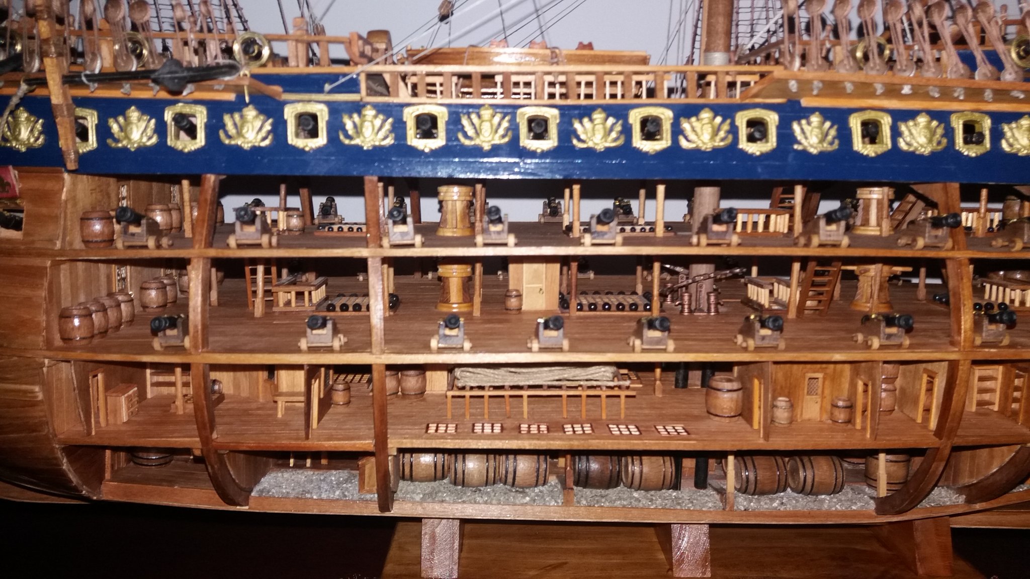
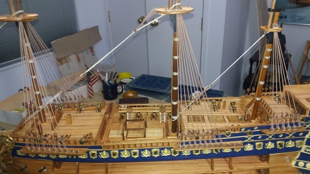
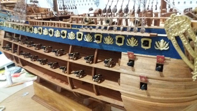
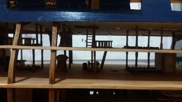
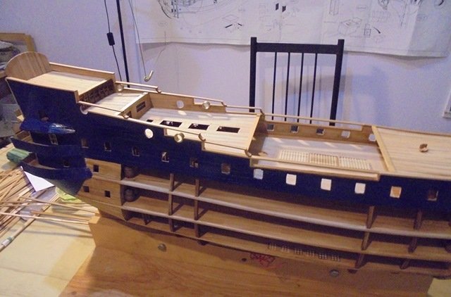
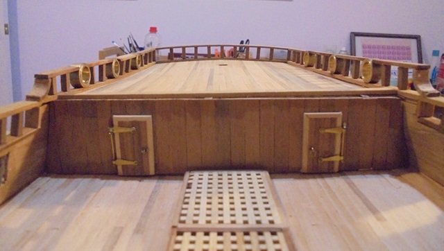
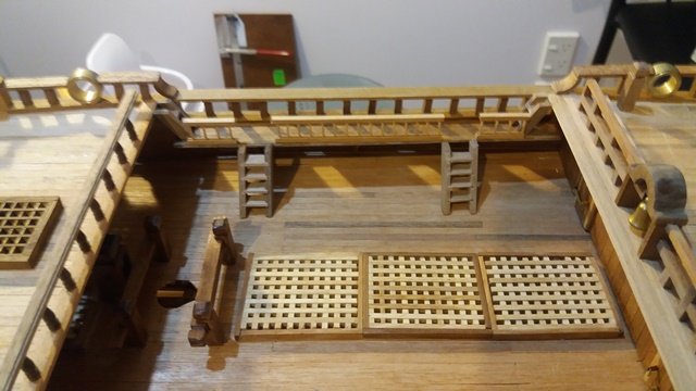
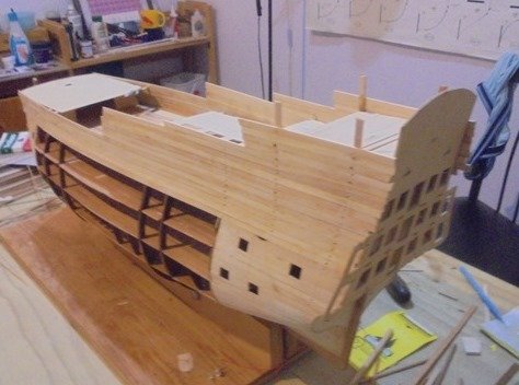
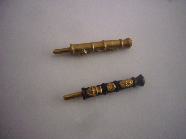
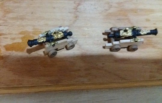
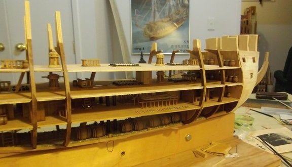
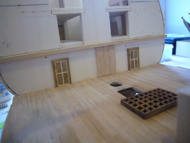
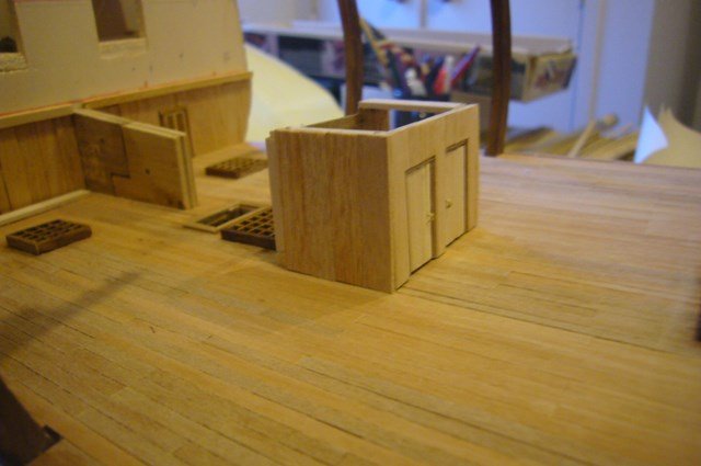
Thanks, Kevin and Learner! The gun decks would be less challenging from a technical perspective because they have much less detail, but I needed to develop logical access routes between the decks and decide how much detail to include. On a real ship, the guns would have had a lot of complicated tackle to secure them to the sides of the ship. But since this ship has no sides, there was no practical way to do all the work. In the end, I decided to just put in the guns by themselves and not include any tackle, buckets, sponges, rams, garlands, etc. Getting all of those things to the right scale and logically working them into the space available was a huge challenge and I felt that a lot of detail at the deck edge would obstruct the view into the interior. Because I was building from a kit, the guns provided were intended to be mounted in blocks inside the ship, so all you see is the ends sticking out of the gunports. They have a peg on the end to mount them in holes in the blocks. I decided to paint them to simulate the iron colour and to highlight the decorations. I sourced some gun carriages, cut off the end of the pegs and rounded them to simulate the ball at the end of each gun and mounted them. I built all of the guns and figured out where to place them but decided that attaching them in place would be one of the last things I’d do so they wouldn’t get in the way. I planked the gun deck. And then installed railings around the companionways, grates and shot garlands, capstans and the pump. It was important to make sure that the pump pipes lined up with the pump. I then installed and planked the middle gun deck. I also built the bulkheads at each end of the gun deck. These would not have existed on the actual ship—I just used them as a way of concealing the structural framework supporting the bow and stern. In retrospect I learned that the decks provided sufficient structural stability that I probably could have extended the decks fore and aft and added many interesting features, but at the time I had no engineering studies to rely on! I then added in the detail on the middle gun deck. I could now breathe a sigh of relief because technically, from now on, I would be building the ship as if I hadn’t done the interior. All of the upper works and finishing touches were based on the original kit design. But this kit was the Mantua Soleil Royal, 80s version--little did I know that the biggest challenges were still ahead!
- 15 replies
-
- 2
-
-
- mantua
- soleil royal
- (and 2 more)
-
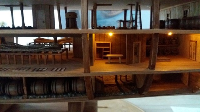
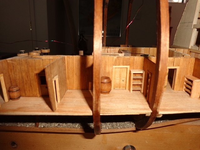
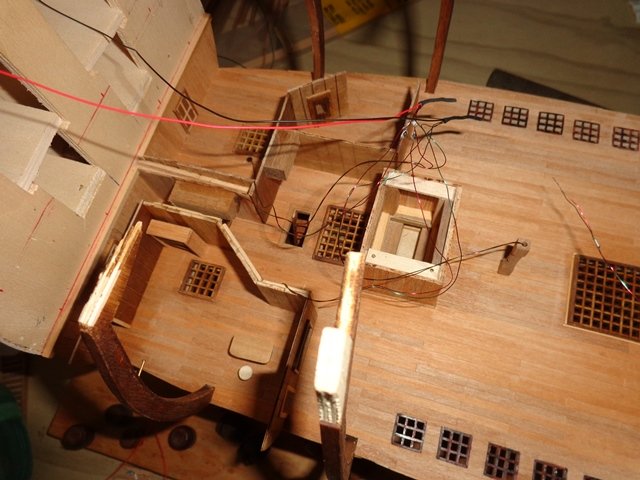
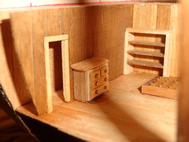
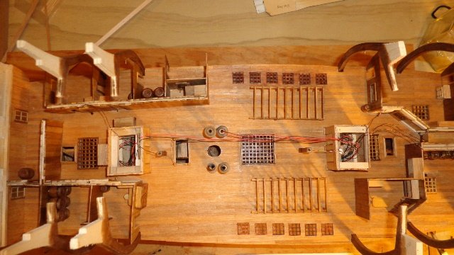
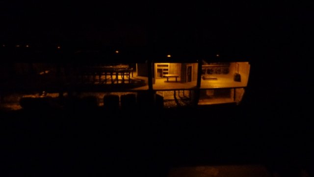
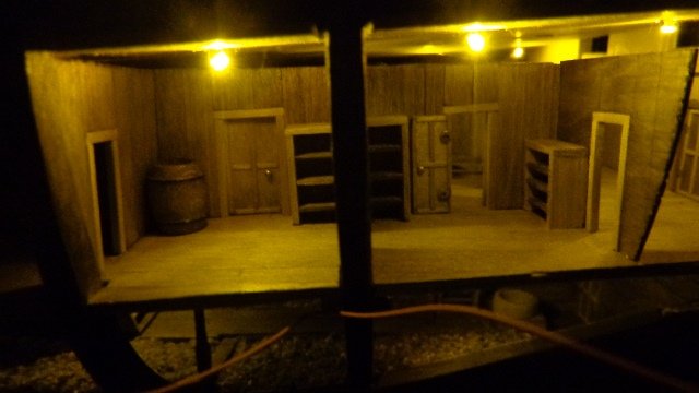
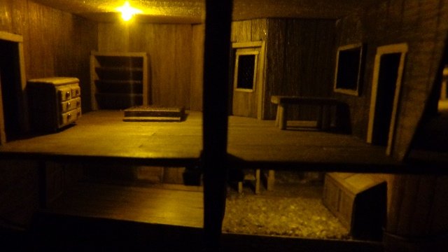
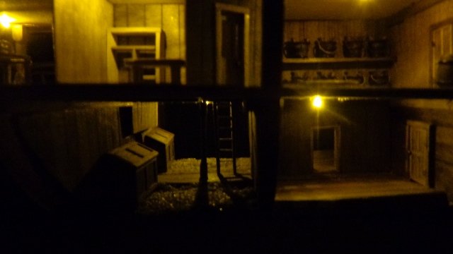
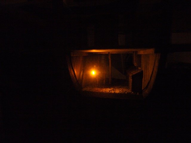
I had decided that I would put the power supply for the lights in the base of the ship and run the wires up through the bottom of the ship. I could attach the wires to the ceiling of the hold. To get the lights to the ceiling of the orlop deck, I hollowed out one of the dowels that represent the pump pipes and ran the wires up through the pipe. I could then fit the gun deck (ceiling of the orlop) and get an idea of where to put in the orlop lights. Before continuing I added some of the features to the various rooms on the deck. I then ran the wiring for the lights to the various rooms. I then cut out the gun deck and fitted it in place, making sure that the mast alignment was still correct. Then came one of the first major moments of truth—a test of the lights to see how they looked. The next step was to plan the gun deck and the guns.
- 15 replies
-
- 3
-
-
- mantua
- soleil royal
- (and 2 more)
-
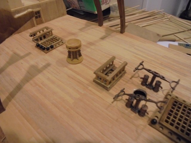
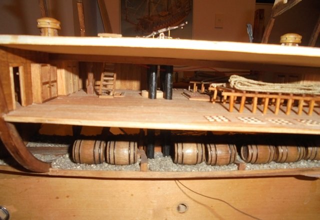
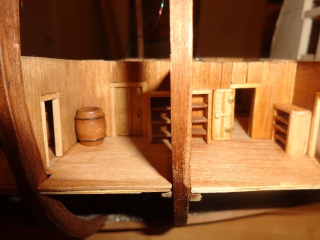
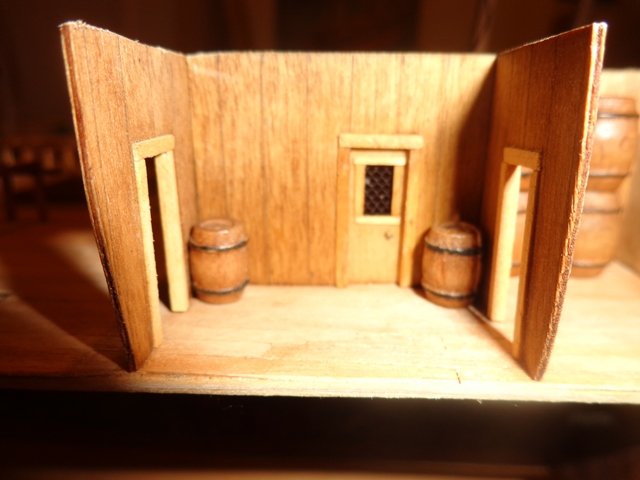
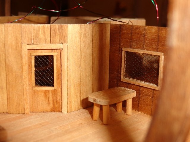
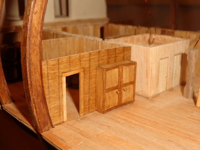
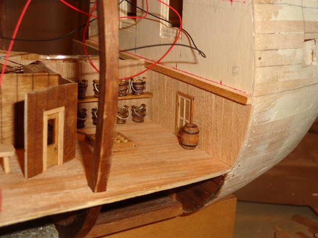
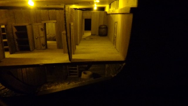
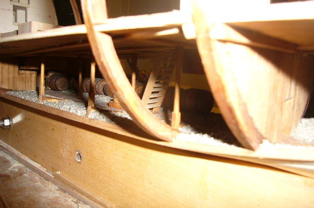
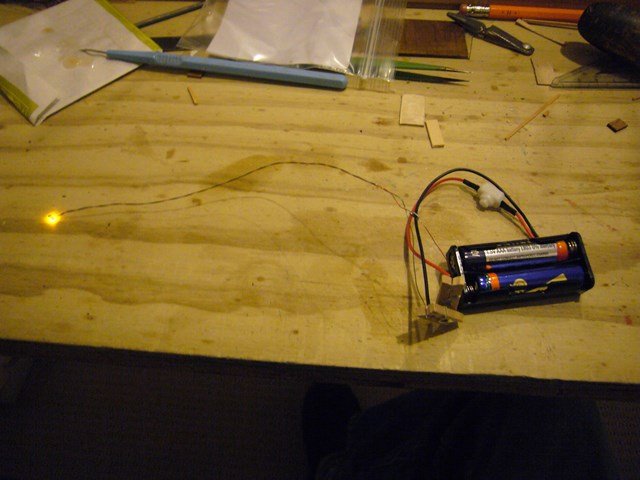
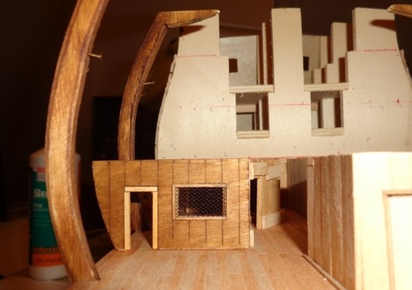
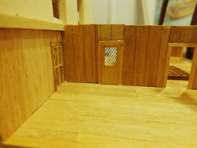
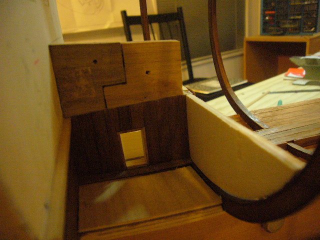
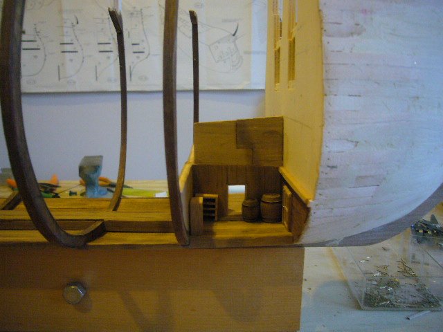
Once I installed the orlop deck I started putting in some of the fittings, including the hanging magazines. As I thought about building the rooms and structures on the orlop deck, I decided that I would try to finish off each deck as much as possible before moving up. That meant going back to the hold and adding some additional detail. It was at that point that I realized that it was going to be too dark to see much of the detail I was building. I researched model lighting and found a company that supplies tiny LEDs and lots of good advice on how to install them. I settled on the smallest yellow LEDs they provided thinking that they might simulate lantern light. I really liked the look but now I had the challenge of how to retrofit the lighting in the hold and also to wire the rooms on the orlop deck. I went ahead and planned the layout of the orlop deck and built the rooms and hallways. The next step was to plan the wiring.
- 15 replies
-
- 2
-
-
- mantua
- soleil royal
- (and 2 more)
-
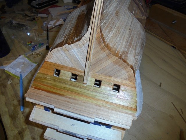
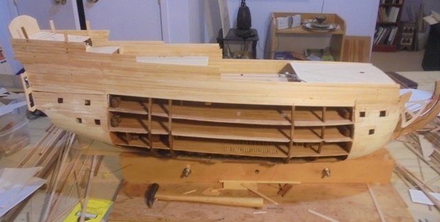
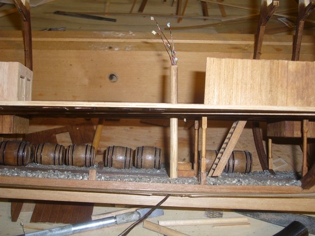
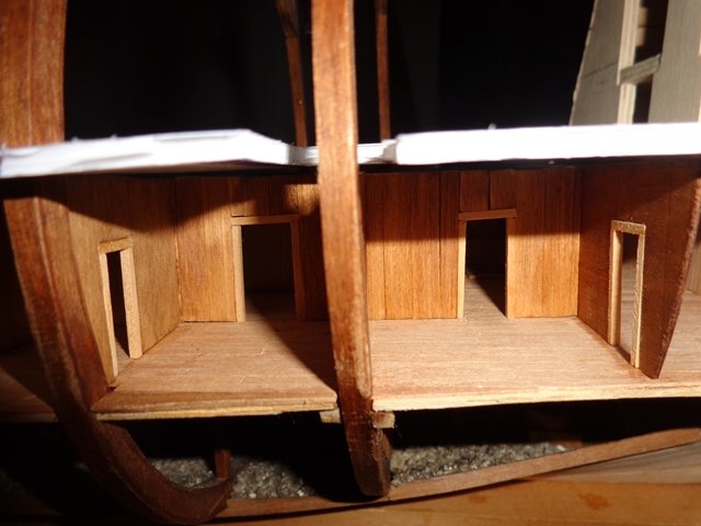
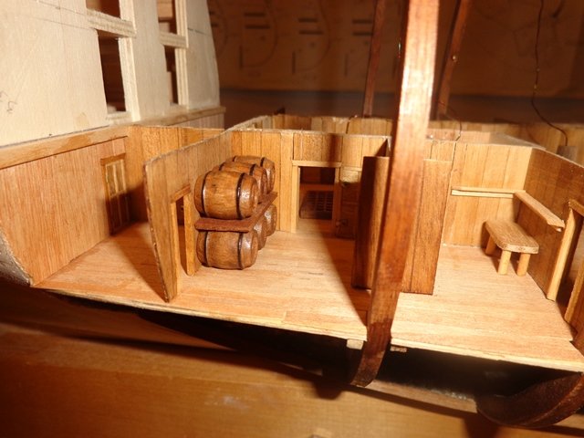
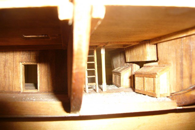
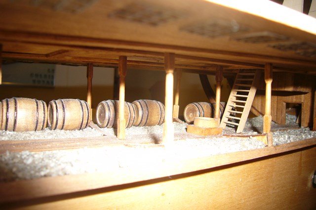
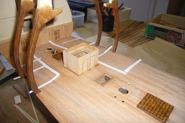
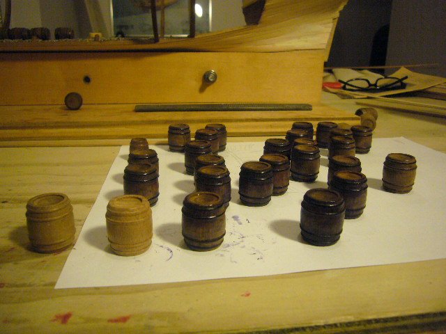
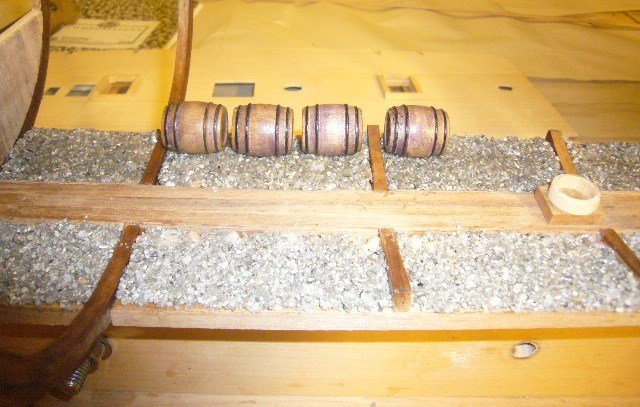
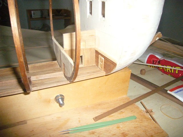
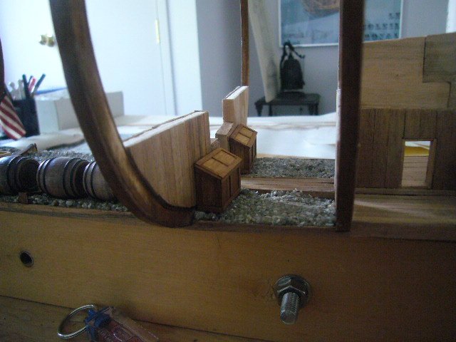
Once I'd planked the bow and stern sections, the next challenge was to determine how to build the hold. I planked the bottom of the ship and that would determine the amount of hold floor I would have to work with. I needed to figure out where the mast steps would be located and then had to allocate the available space to create a reasonable replica of how the hold in the exposed areas would look. I discovered that the first thing I needed to do was find out how the orlop deck, the first deck above the hold, was laid out. This was important because structures on the orlop deck, especially the hanging magazines, would impact the layout of the hold. There are also steps and ladders between the decks and I needed to know where to put them. At that point I cut out the orlop deck based on the plans I had drawn earlier. I had had to decide how to do the decking. I could do it the way they did when they built the ship, which is to run beams between the ribs and then lay what were known as carlings at right angles. That would form a framework over which deck beams were laid. That was a great way to do the decks but I was concerned about (1) keeping them even and (2) ensuring that the structure was solid. So I decided to cut each deck out of a sheet of plywood, cut out the openings and plank over the plywood to create the appearance of decking. To prevent warping I did run beams between the frames. I then determined where the masts and other structures would be located and cut holes in the ply. Once I was happy with the positioning of the deck, I started to put in some of the hold fittings and fixtures. I knew I’d need a lot of barrels and sourced various sizes of barrels and prepared them by painting the hoops and varnishing them. I built some walls between the two most fore and aft strakes and used aquarium gravel to simulate ballast. I kept a part of the false keel to provide additional structural support and then needed to make a number of decisions about how to use the space. I cut doorways wherever I could to reflect that the crew would have had to move through these various areas. Although technically and historically inaccurate, I thought the layout made for interesting opportunities to put in additional details. The next task was to plan the orlop deck.
- 15 replies
-
- 2
-
-
- mantua
- soleil royal
- (and 2 more)
-
Thanks Kevin!
-
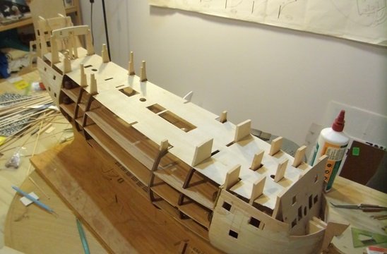
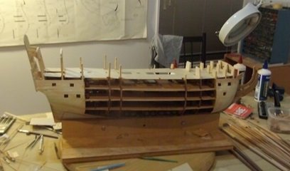
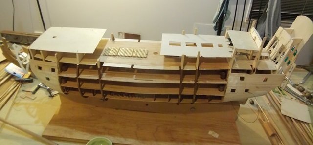
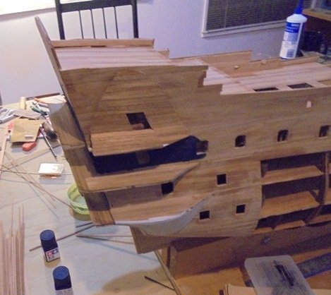
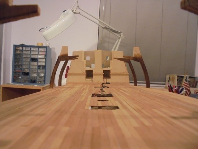
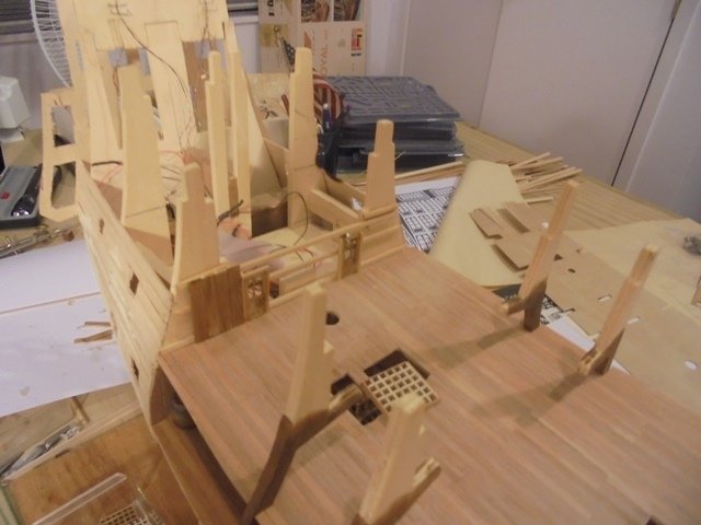
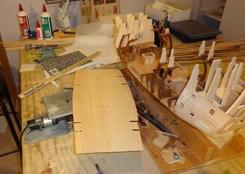
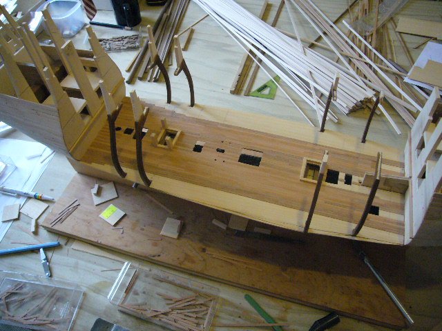
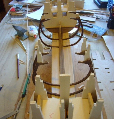
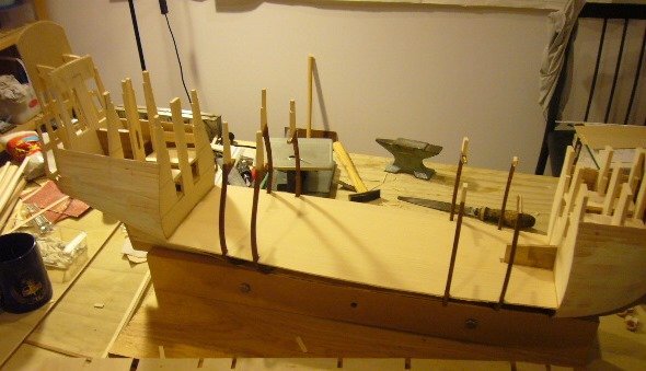
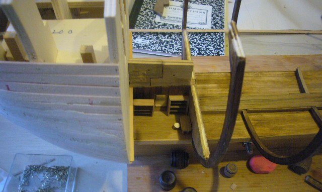
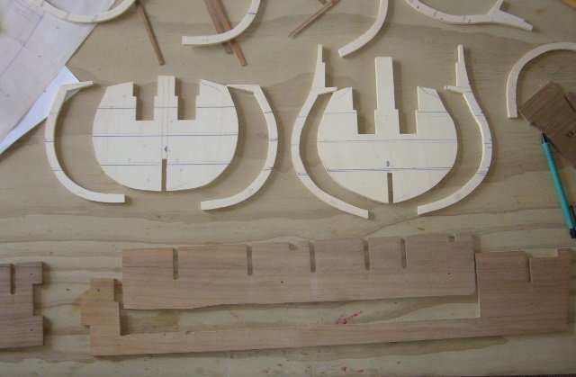
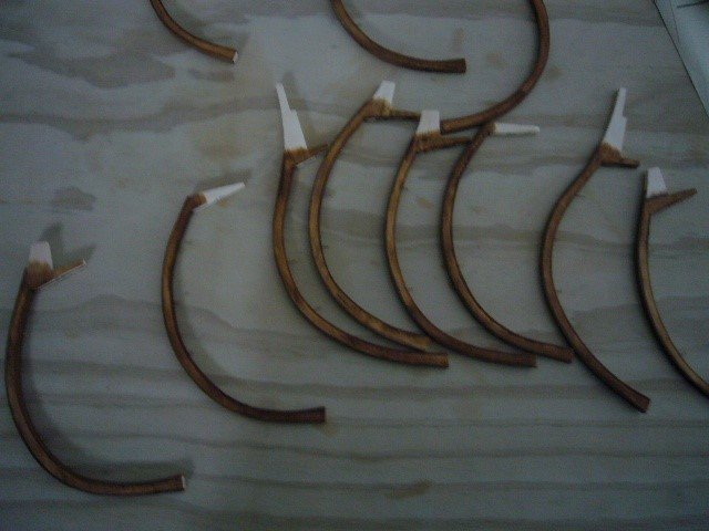
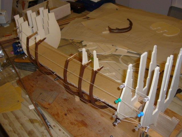
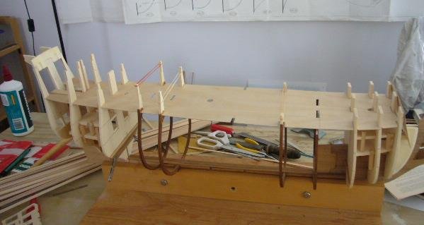
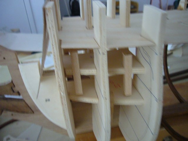
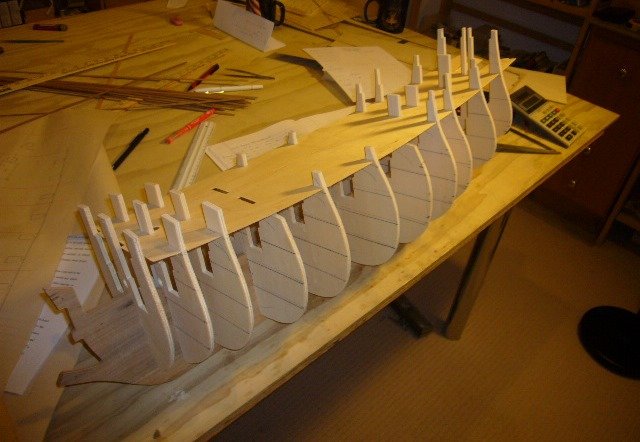
The next task was to draw the details of each deck. I did this using the Victory plans and modifying them for scale and also for features that I knew the Soleil Royal would not have. For example, the Victory had a very modern pumping system and stove that would not have been present on the Soleil Royal. I knew that there was no way I could build an exact replica and that was never my objective. I did it for the challenge and to create an interesting and attractive model. So from now on, any decisions as to historical accuracy or scale were decided based on aesthetics rather than history as well as what was practically possible given the scale and the structure I was working with. It was now time to make some difficult decisions about construction. My two big concerns as I made these decisions were (1) warping and (2) support of the decks. In the scale that I was building, the decks could be no more than 5mm thick. They would be well supported fore and aft but would have very little support midships. During construction, because I envisioned building the ship from the bottom up, there would be very little support and when building one of these models you are constantly turning them and pounding and filing and sanding. So I needed to come up with a design that would be strong but also enable me to expose the open decks as much as possible during construction. With two thirds of the hull planks removed and with no interior framework, I was concerned that there may be stresses that would distort the structure either during or after building. Closely tied to the concern about warping is the question of how to support the decks to prevent them from sagging through the unsupported middle spans. Initially I thought that I would install the masts and build the decks around the masts and that they would provide support, but there was an even bigger problem. The open area of the ship would be from the upper deck down to the hold. The walls around the quarter deck, poop decks and foc’sle needed to be intact in order to provide support for the chain wales which hold down the rigging. There is also a lot of interesting decorative work on those walls that I didn’t want to sacrifice. In order to be able to build the outside walls and to maintain the sheer and contours of the ship’s sides I needed to be able to build some sort of support for the decks. That led me to decide to use the frames supplied with the kit. I decided to cut them to make them look like the ribs that the actual ship would have. They would provide the needed support to build the walls and would also solve the problem of how to support the decks because I could attach the decks to them as I worked up. I cut the frames from the plywood pieces supplied with the kit, and planked them with walnut to hide the plywood appearance. I also had to cut out a section of the false keel that is provided by the kit because it would block the view through the hold. I then attached them to the keel to form the outline of the ship with a cardboard placeholder to check deck alignments: Securing the ribs and positioning them properly was a huge challenge and took a few tries. When I finally got them where I wanted them I decided that I had too many and took out the two in the center to open up more of the decks. I then made a template of the lowest deck above the hold (the orlop deck) to make sure that I would be able to fit in the decks with the ribs in place and also to gauge how best to support the decks when in place. All of this helped to confirm my measurements and deck layout organization. The next step was to proceed to build the ship as close to the original plans. As I mentioned, I would be building the bow and stern exactly as planned for the model. I put in the false decks and cannon blocks for the gun ports that would be planked, fitted the bow and stern structures and did the first layer of planking in the areas that would be covered.
- 15 replies
-
- 4
-
-
- mantua
- soleil royal
- (and 2 more)
-
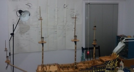
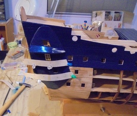
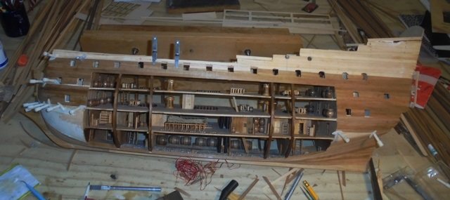
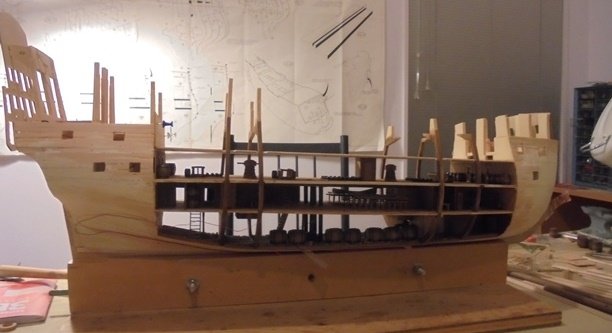
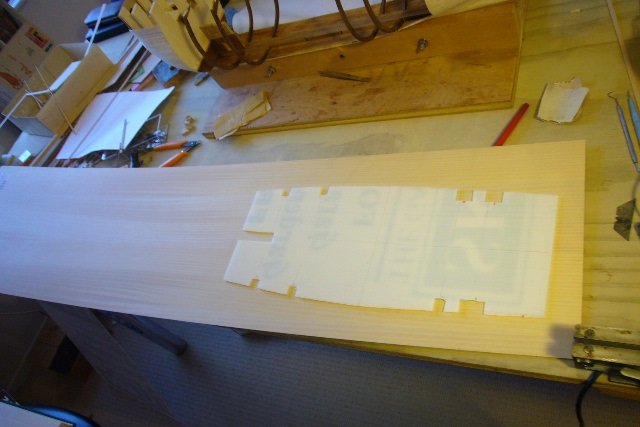
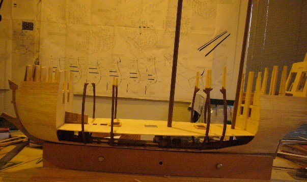
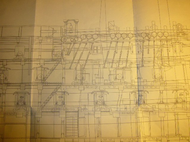
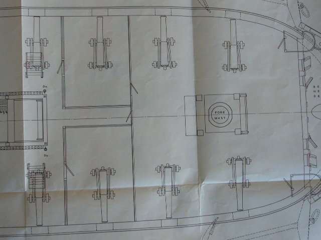
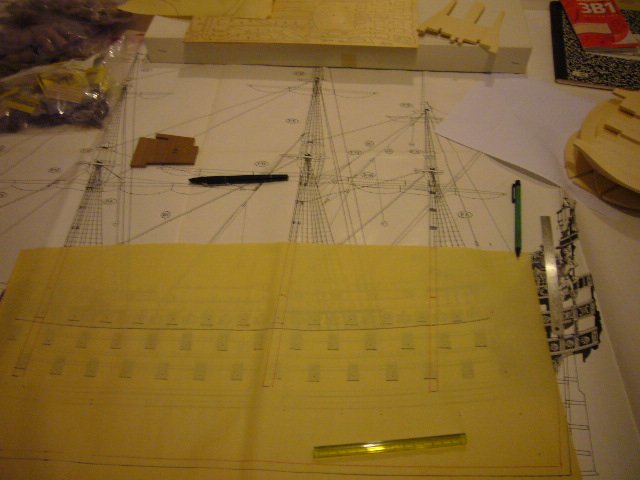
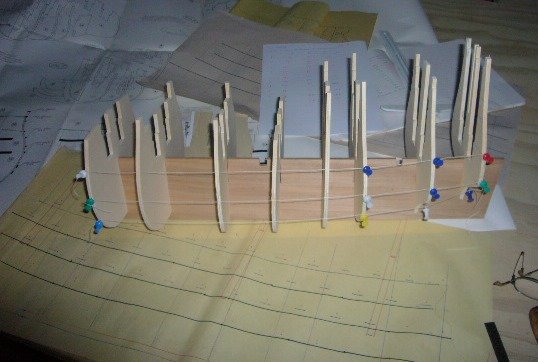
The last two ships I did were the Mantua Victory and the Panart San Felipe, and the next one in the pipeline was the Mantua Sergal Soleil Royal. Although the Soleil Royal would present a challenge in terms of complexity, it wasn’t going to be substantively different than the previous two big ships. I wanted to do something a little different. Of all of the ship models I’ve built, the one that seems to interest most people is the cross section of the USS Constitution. In a true "it seemed like a good idea at the time" moment, I decided to spice things up by building the Soleil Royal with the sides open and with the inner works displayed. I started the project a while ago and haven't done a build log because I didn't want to start a log I couldn't finish. But the good news is that I finally finished the project and I'd like to share the build experience with you. The bottom line is that I learned a lot and in retrospect would have done some things differently. But I'm happy with the end result. As you can see, I used all of the materials in the kit, so in addition to describing the cutaway work, I'd also like to share some ideas on building the Soleil. In planning the project, I had three big challenges. First, I wanted to use all the metal decorations and as much of the kit as possible, so I was limited as to size and scale. Second, I was concerned about structural support and warping, given that there wouldn't be the normal internal structure of an actual ship or model. Third, and most challenging, I had no real idea how the actual ship looked inside. There was a lot of information on ships of that period and the Wasa and Victory are available for study. I was really lucky and found a book in the Auckland Library by the guy who ran the project to restore the Victory after it was damaged by bombs during WWII. Accompanying the book is a box containing 17 (huge) sheets of plans. There is one for each deck and it was exactly what I needed. The plans had more than enough detail and with my other research I was now able to create a reasonable (but admittedly not 100% certain) picture of how the Soleil Royal may have looked inside. My first challenge was to copy the plans which I managed to do by tracing. The Victory plans are about 30% bigger than the model of the Soleil Royal so the next challenge was to draw detailed plans to scale based on the actual dimensions of the model. I needed to keep to the model dimensions because I was going to use the stern and bow decorations provided with the kit and therefore had to use the kit dimensions. Every time I thought I had solved all my problems, something new and interesting would come up. As I tried to map the dimensions of the Victory deck plans onto the Soleil Royal model plans, things weren’t making sense. I realized that the problem arose because the ship model takes certain liberties with scale in order to make the model look good. These ship models, because of their scale, necessarily have to make tradeoffs between aesthetics and historical accuracy. For one thing, the guns and gun ports are larger than they would have been on a real ship and the rigging is much less complex. Unfortunately, because I was going to use the bow and stern, as well as the quarter deck, forecastle and poop deck as provided in the model, I had to retrofit the revised dimensions to make everything look proportional. I built up a partial structure using the plywood frames provided in the kit and transferred my deck dimensions to the model: Once I got the frames and strings aligned properly I marked the deck positions on the frames. I then drew a plan of each deck looking down from the top. I drew a horizontal line depicting the keel in the center of a sheet. I then marked a vertical line at the location of each of the frames. I then laid the marked up frame centered on the horizontal line and marked the outer edge of the deck at each point. This gave me an exact outline of the area of the deck which would be exposed. I don't want to overwhelm one post with all of the history, so I will add more information in future posts.
- 15 replies
-
- 6
-
-
- mantua
- soleil royal
- (and 2 more)
-
Hi Andy--I'm late to the party as usual! Congratulations on your Sovereign of the Seas. I'm about to tackle the same project and have noticed that everyone seems to follow the instructions and delays planking the bottom part of the hull until a lot of the deck work is finished. In your build log you raised the question of whether there was a reason for that. Having done the build, was there a reason? I have a strong preference to do all the planking first and then work on the decks. The sanding and moving of the ship during planking makes me not want to do a lot of delicate work first. Would love your thoughts. Thanks! Thomas
-
Congratulations! An amazing accomplishment and I really admire your decision to tackle the carving. What's your next project. PS. I'm still behind you but only by a few days!
-
Really looking good--what advice do you have for ensuring the masts are all perfectly straight and aligned? It looks like you are building them up as you go. I like that approach but it makes keeping everything straight a challenge.
-
Thanks! That is one of the interesting challenges with bashing this kit--the actual ships that still exist like the Wasa and the Victory are 100 years earlier and later, so you have to extrapolate! Whether or not the actual ship had them, I think they are a nice addition.
-
Looking good and you're in the fun part now! I was wondering what made you decide to put the railings around the top? Haven't seen that before.
-
Thanks
-
Hi John--Looking good! How did you decide what sizes of rigging lines you need and how much you need. Thanks!
-
Hope you feel better soon! Looks like you are using the kit materials for the boats. I've always found boats one of the most challenging things to do and I'm dreading the experience with the quality of this kit. Good luck!
-
Thanks for reminding me of that amazing build. I could say that the room belongs to a junior officer who just has to deal with people using his room!