


Clark
-
Posts
238 -
Joined
-
Last visited
Content Type
Profiles
Forums
Gallery
Events
Posts posted by Clark
-
-
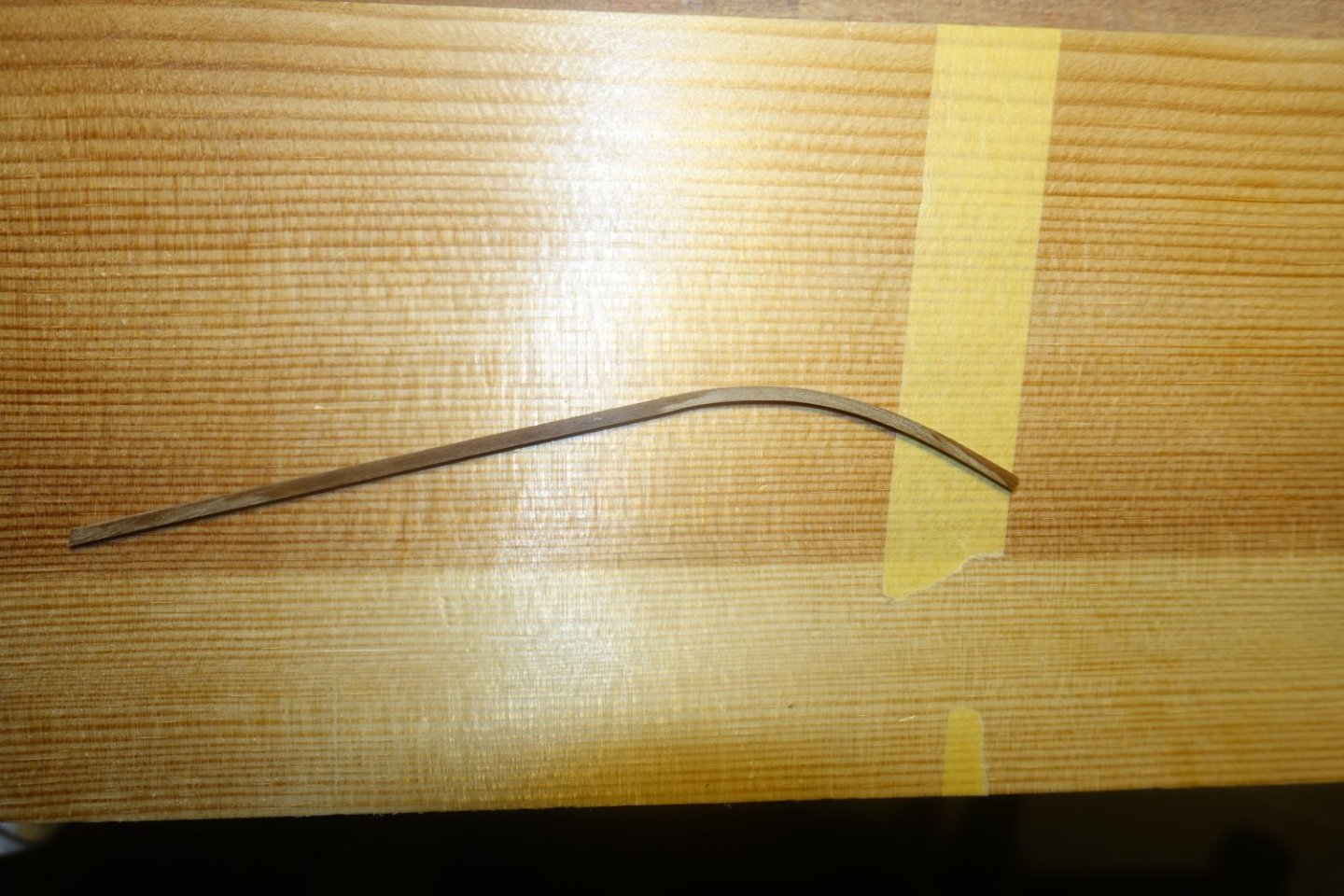
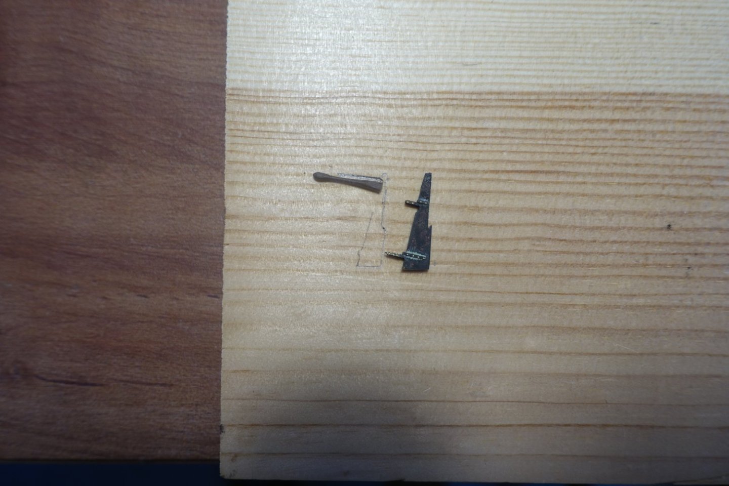
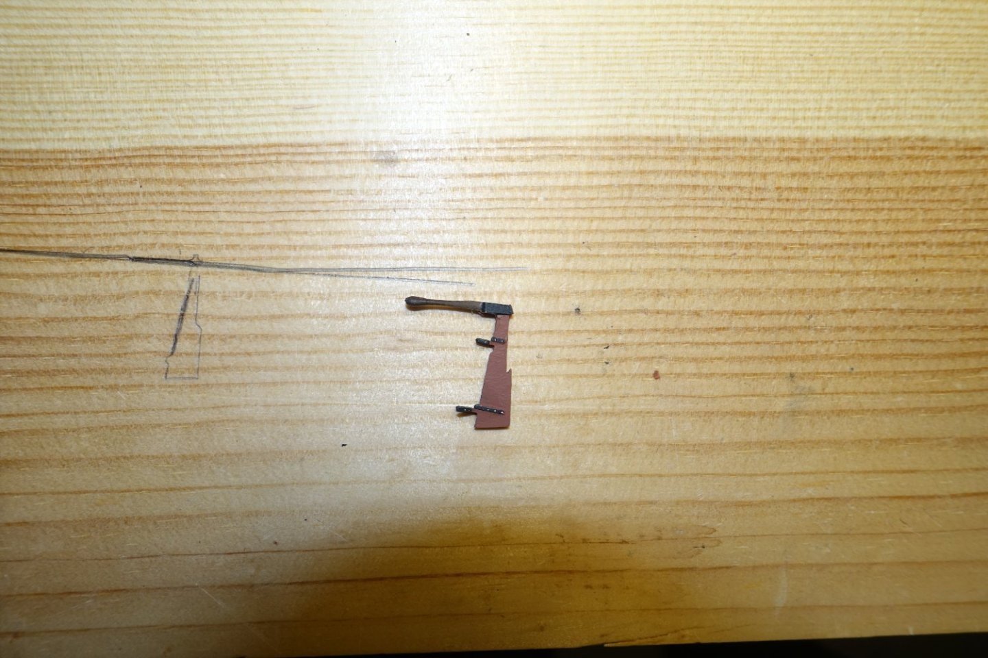
Davit and rudder
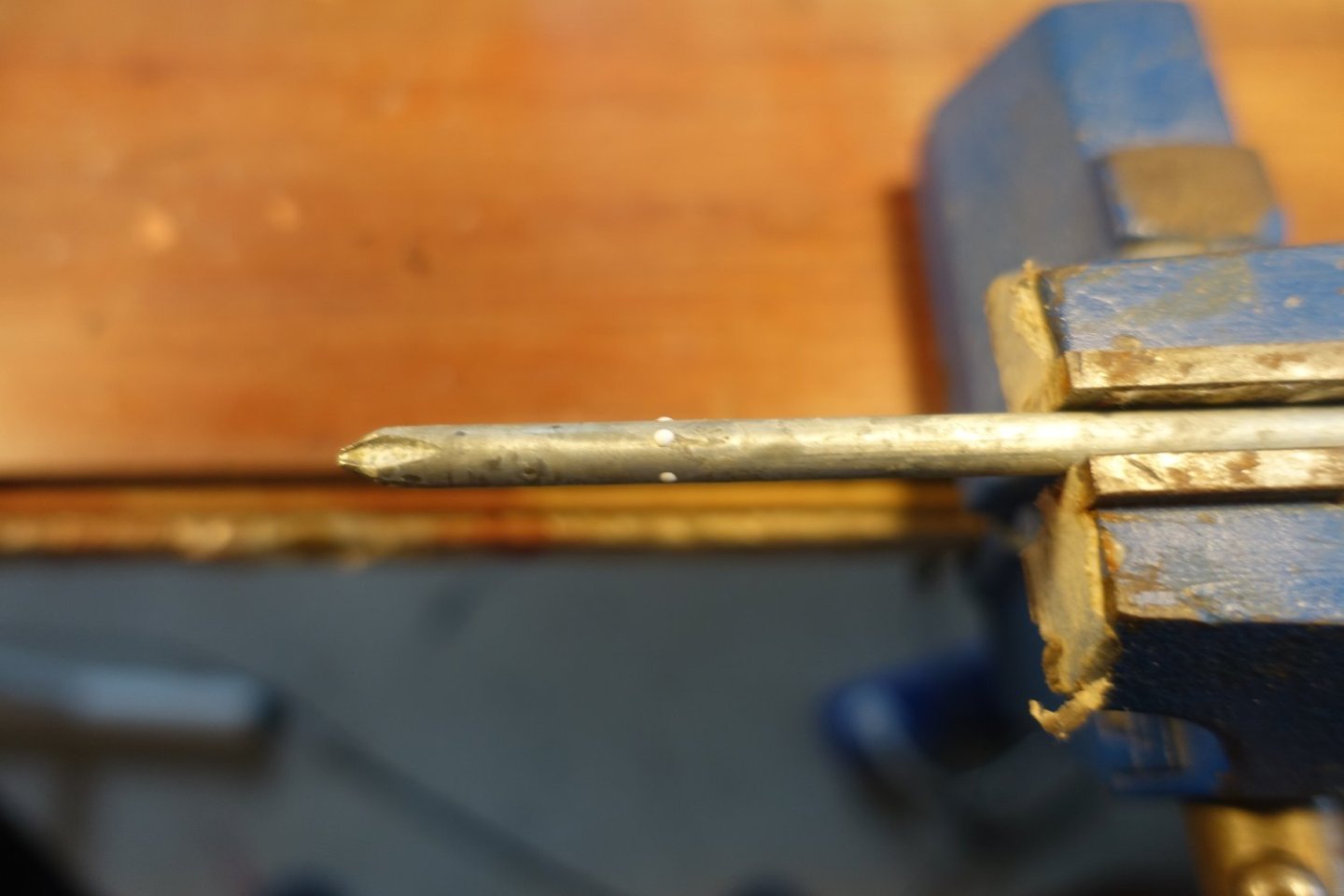
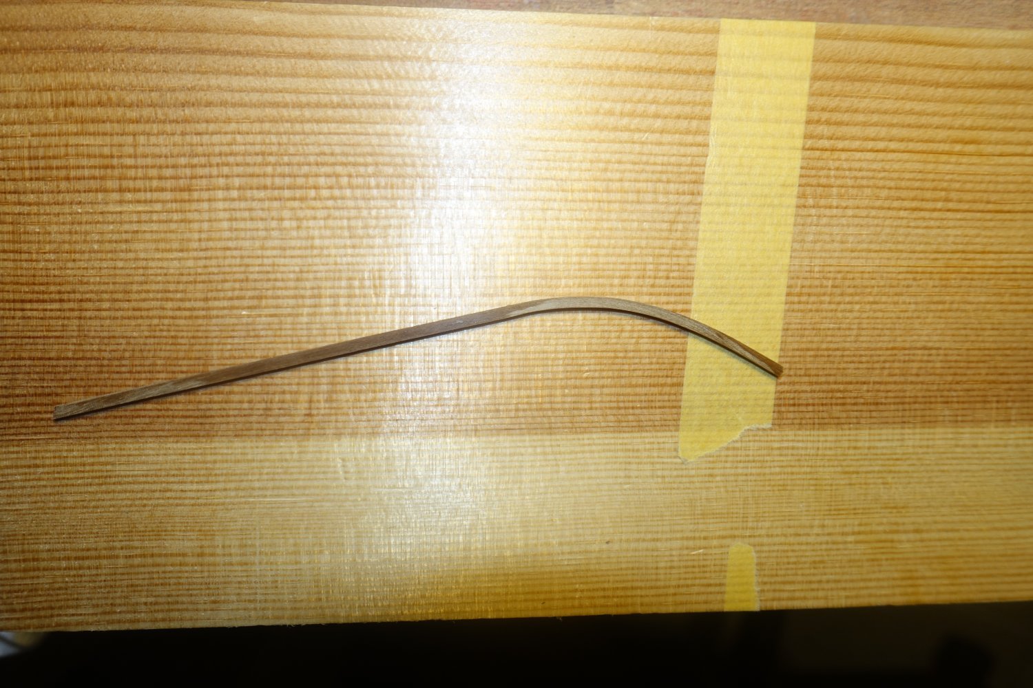
I didn't quite like the davit from the kit, since it seemed to fragile. So I bent a 2 x 2 mm strip and sanded it to size.
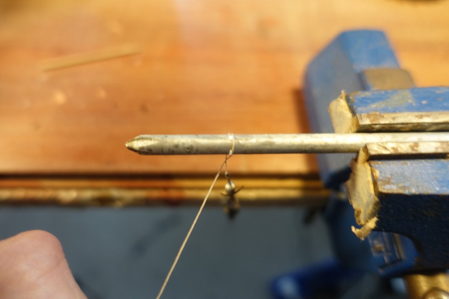
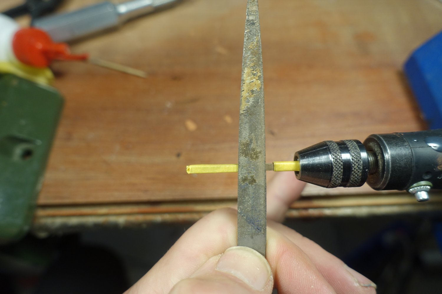
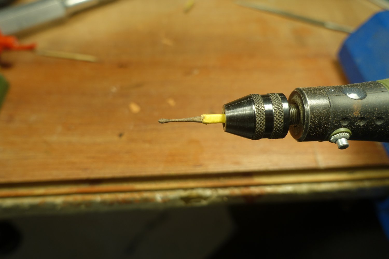
Davit with brass rod " sheave ".
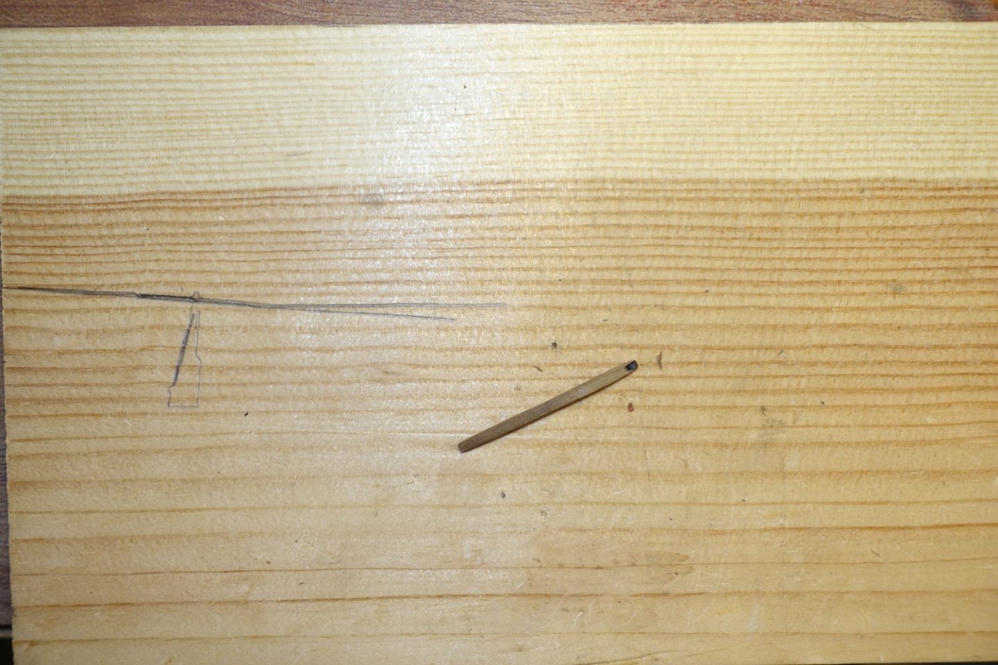
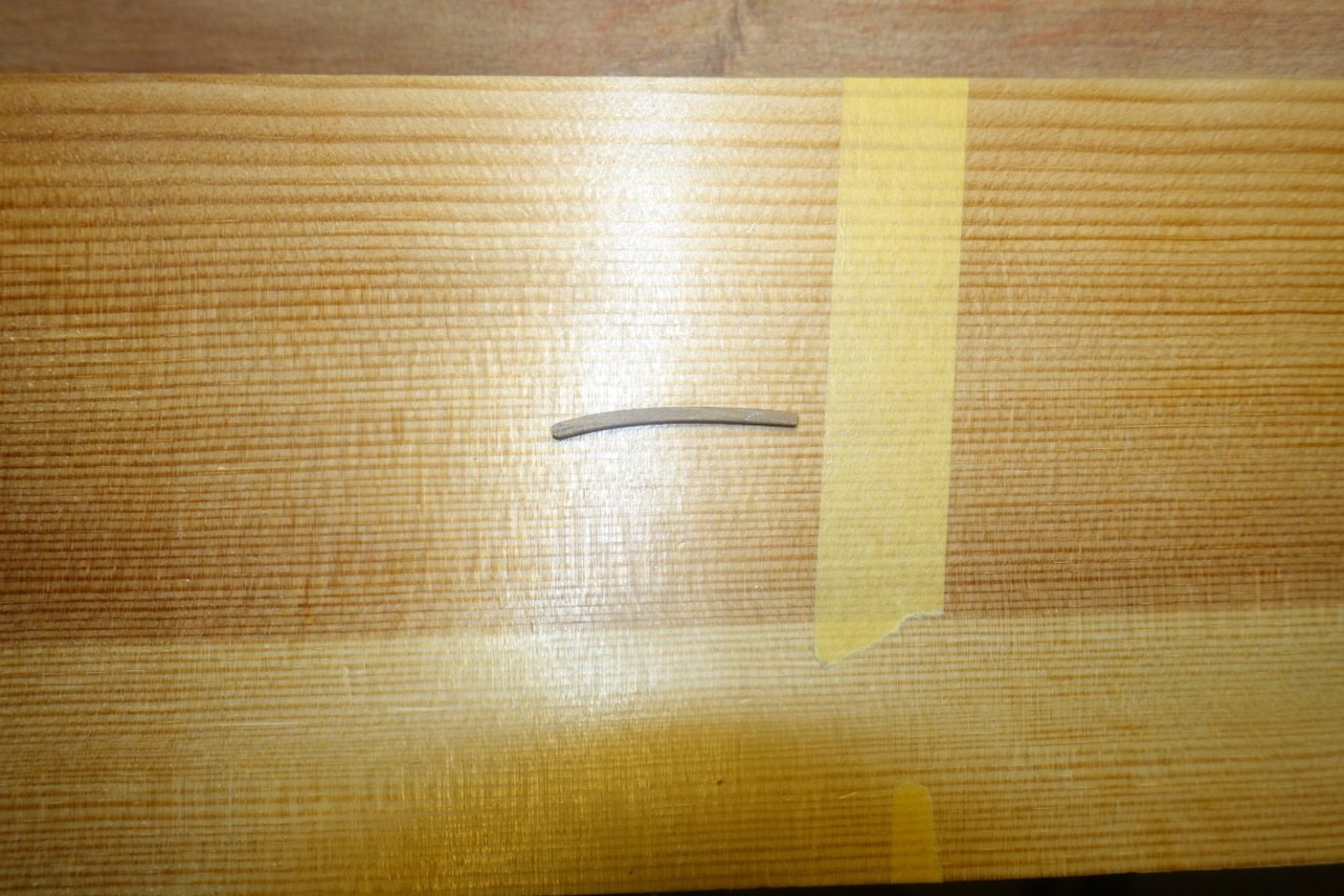
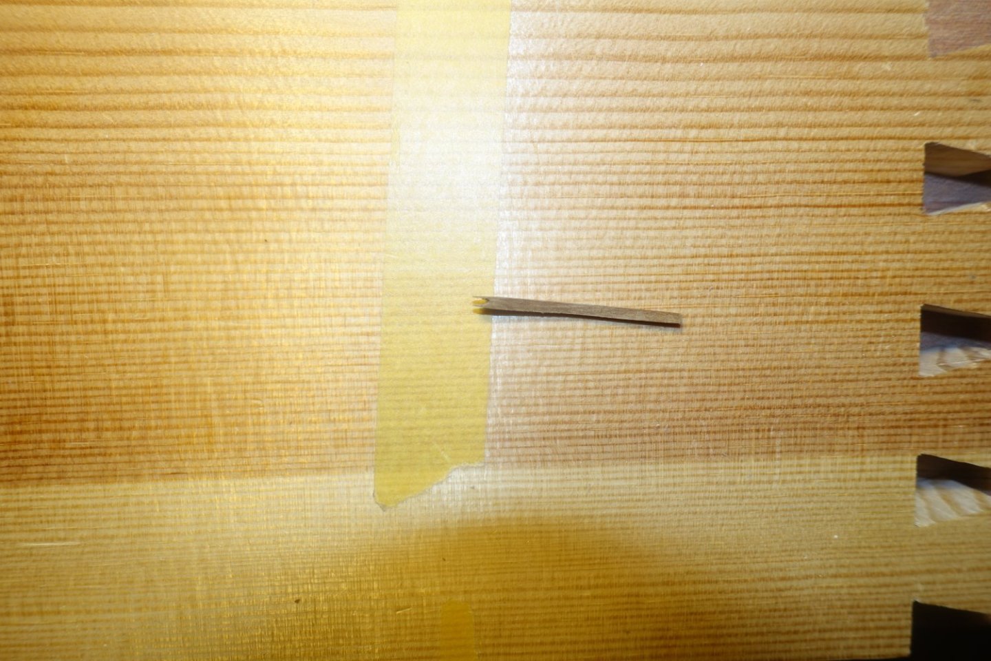
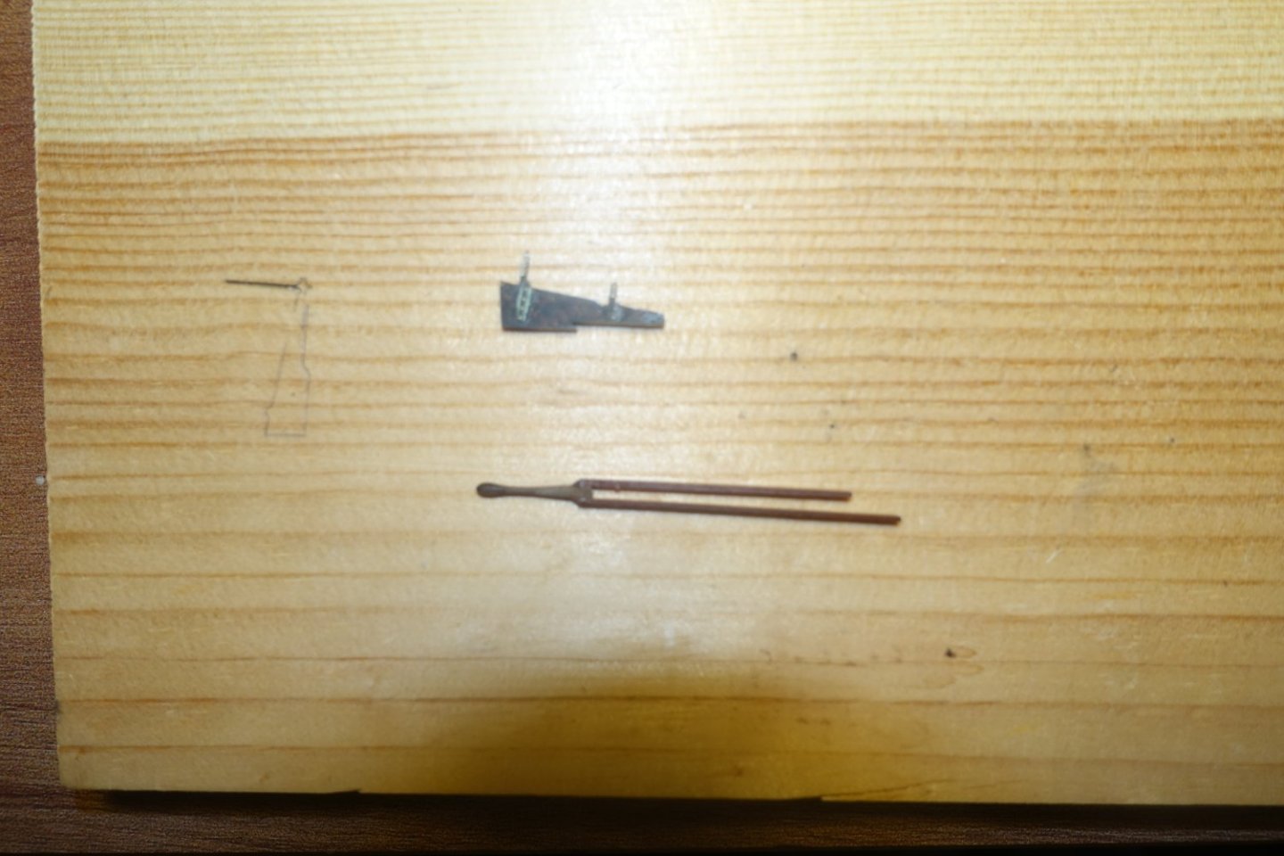
I made a rudder tiller from a 2x2mm strip, which I sanded accordingly


The tiller was filed to the width of the rudder and the bevel adjusted. In the picture, the brass rudder cover has already been treated with a blackening solution acting quickly.
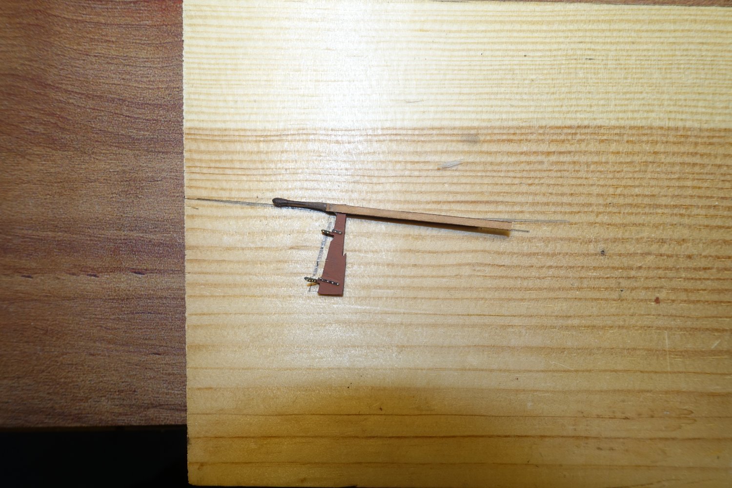
Two remaining pieces of the sit support strips were glued to the sides of the tiller
Once dry, the rudder was fitted in the strips.

A transverse strip was added at the back, the rudder was painted with mahogany wood paint, the rudder hinges and the tiller hinge black.
Rudder and davit are attached and secured.
- KARAVOKIRIS and bruce d
-
 2
2
-
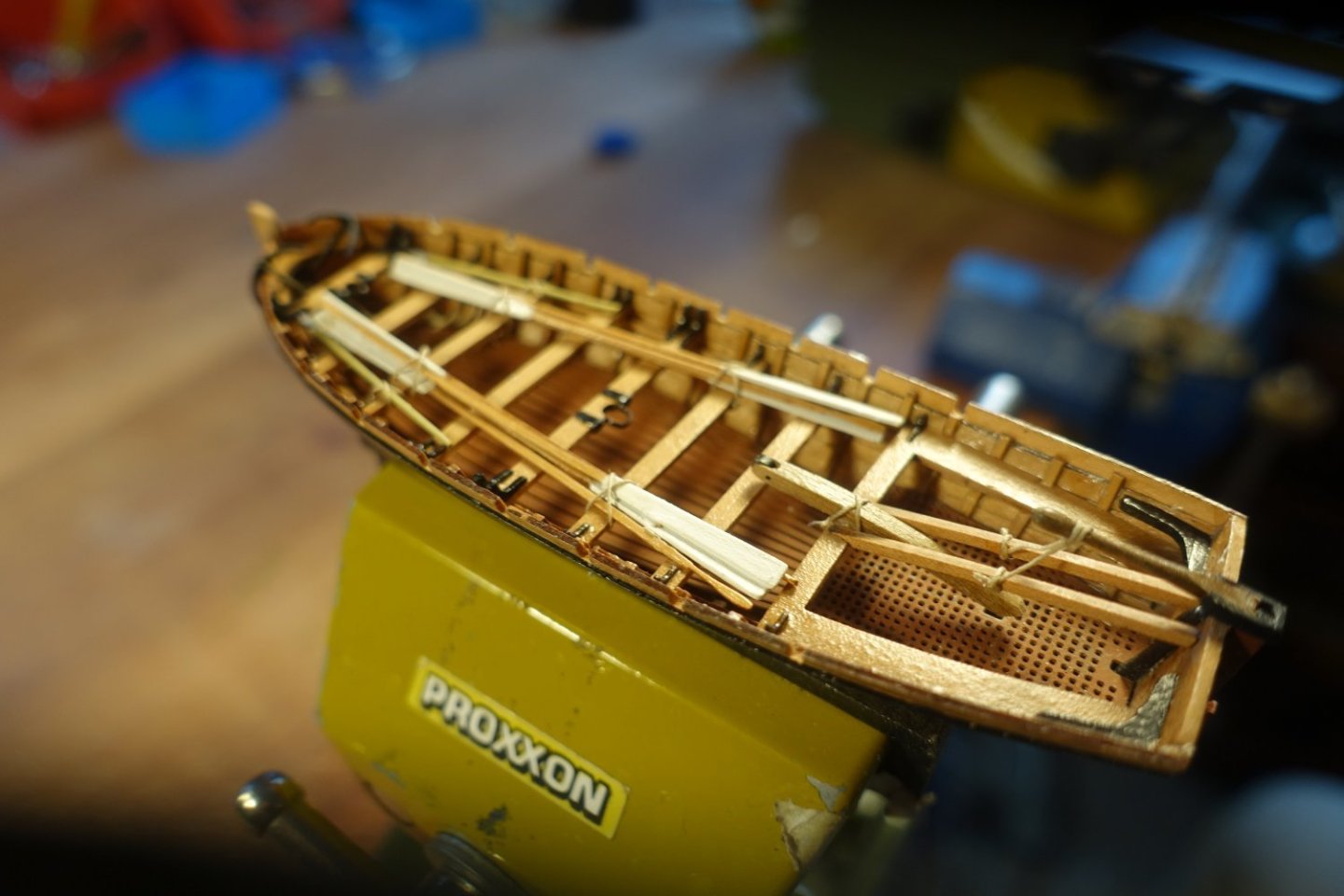
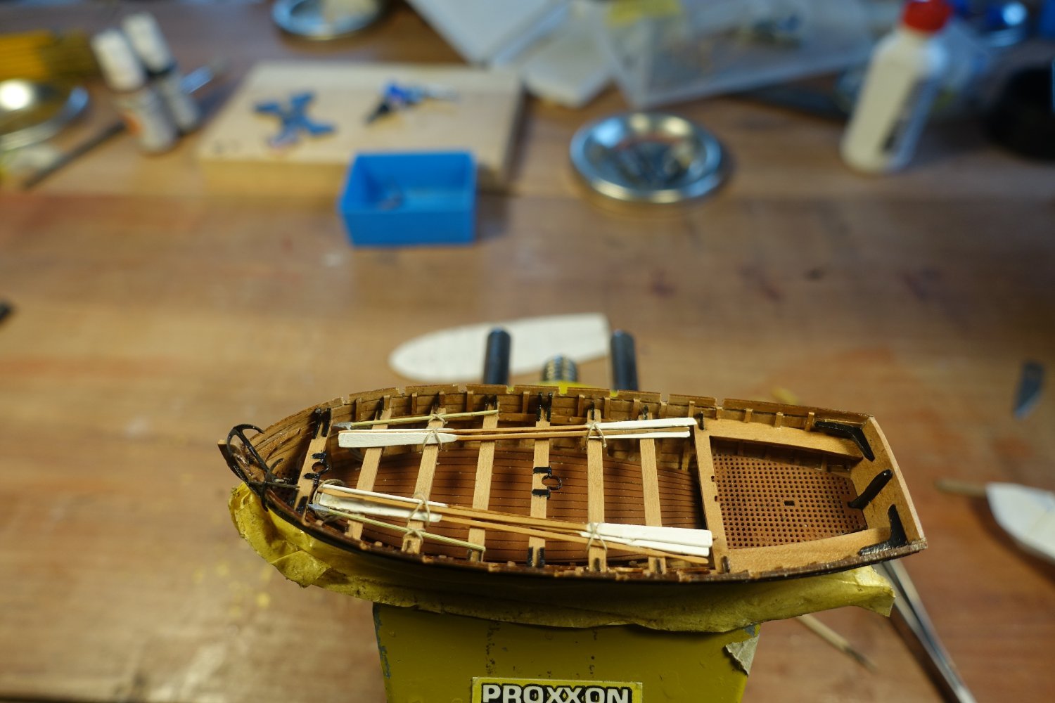
Anchors, oars and hooks
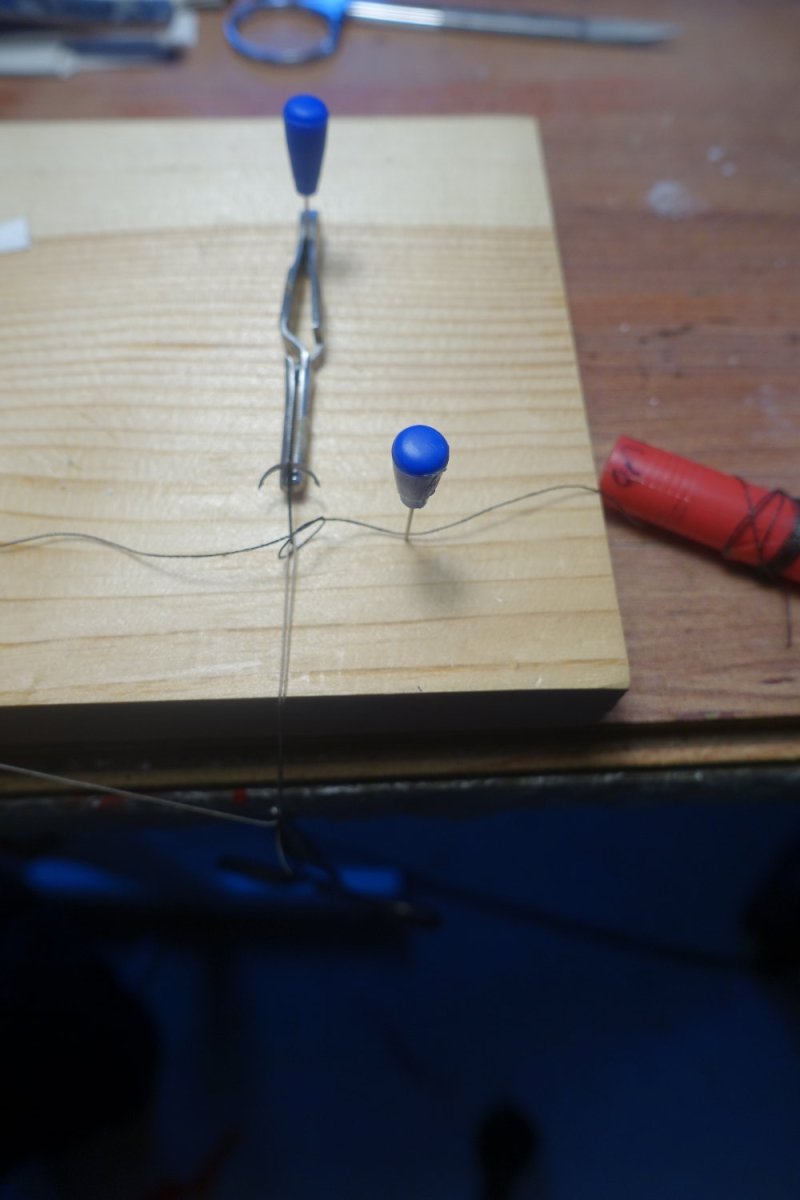
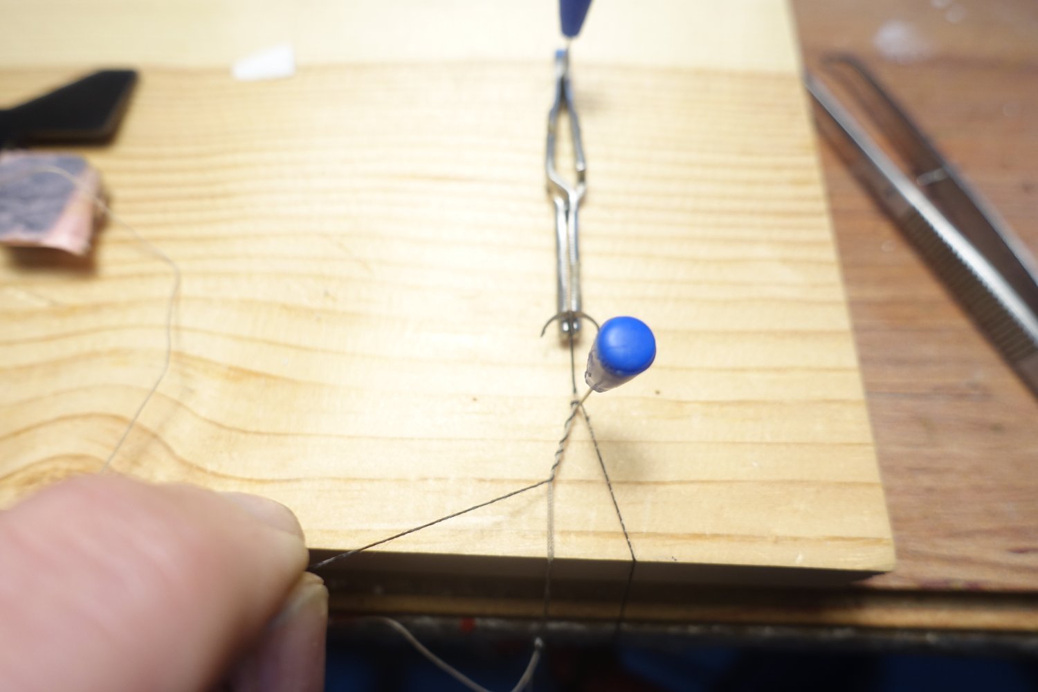
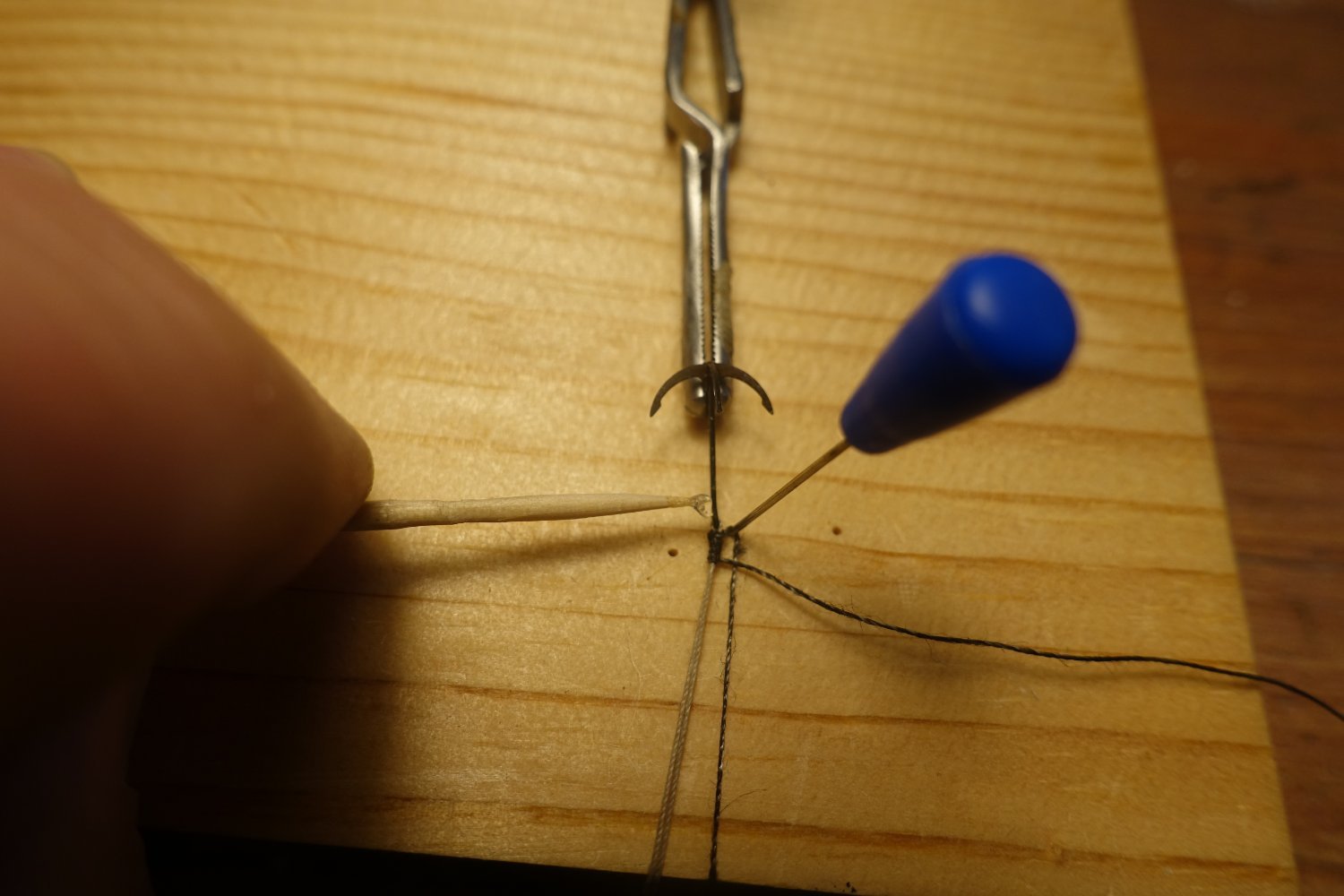
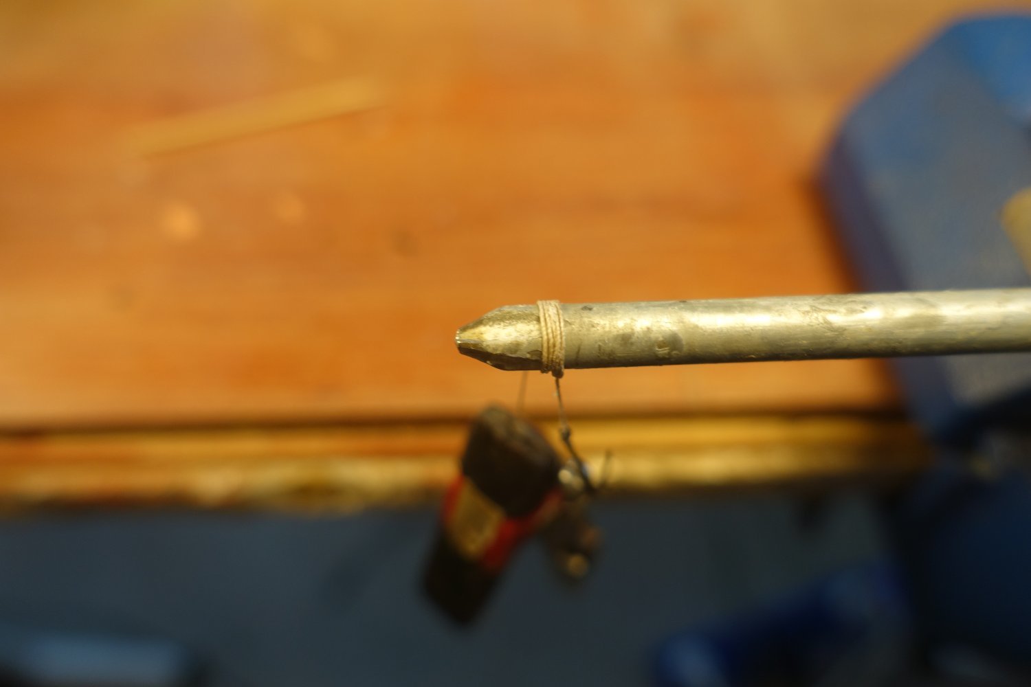
Anchors were supplied with a rope.


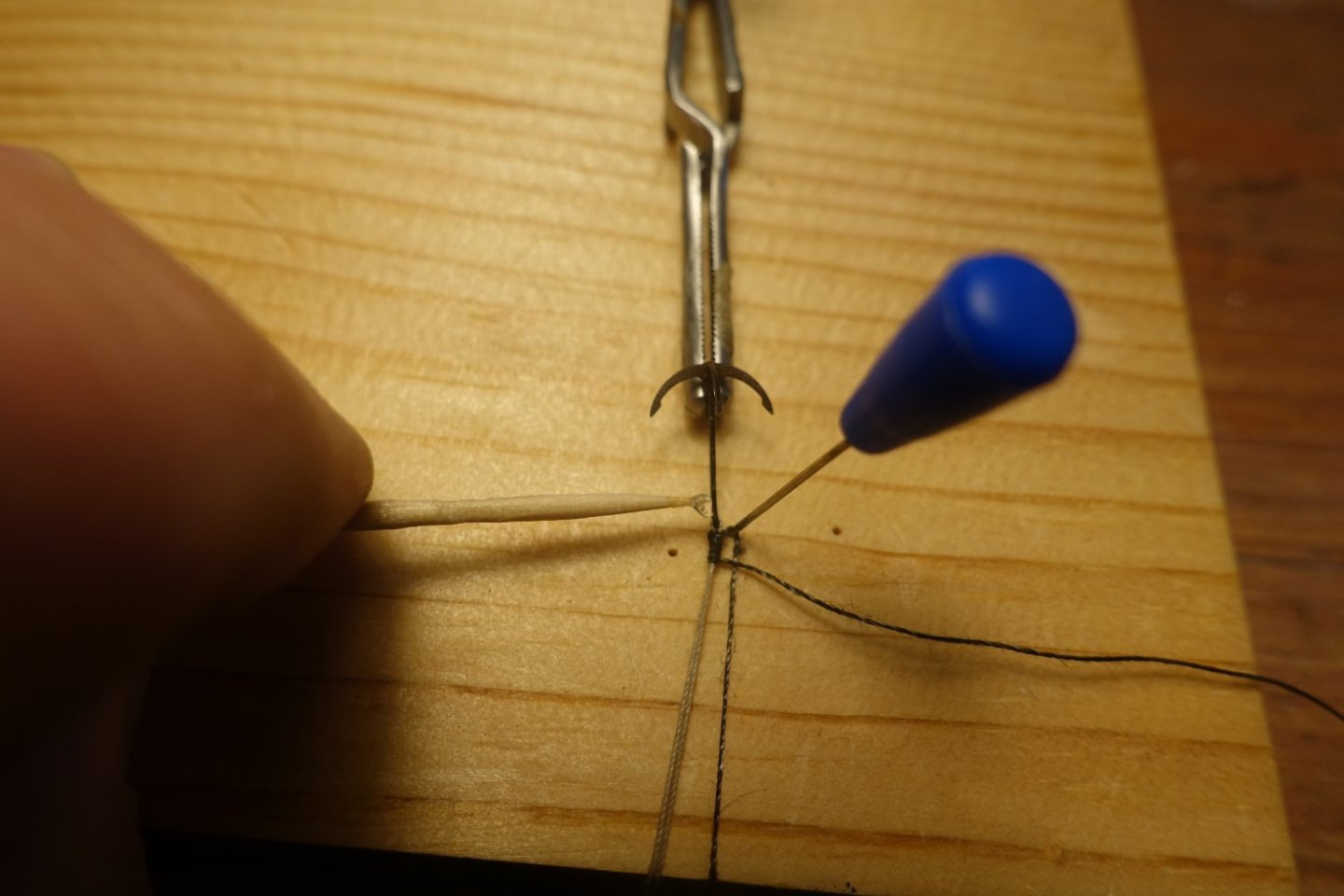
I used a screwdriver to roll up the anchor rope, put some PVA on the rod and then wrapped the anchor rope around it.

The anchors were stored in the bow area.

Oars and grappling hooks were secured on the thwarts.

- bruce d and KARAVOKIRIS
-
2
-
-
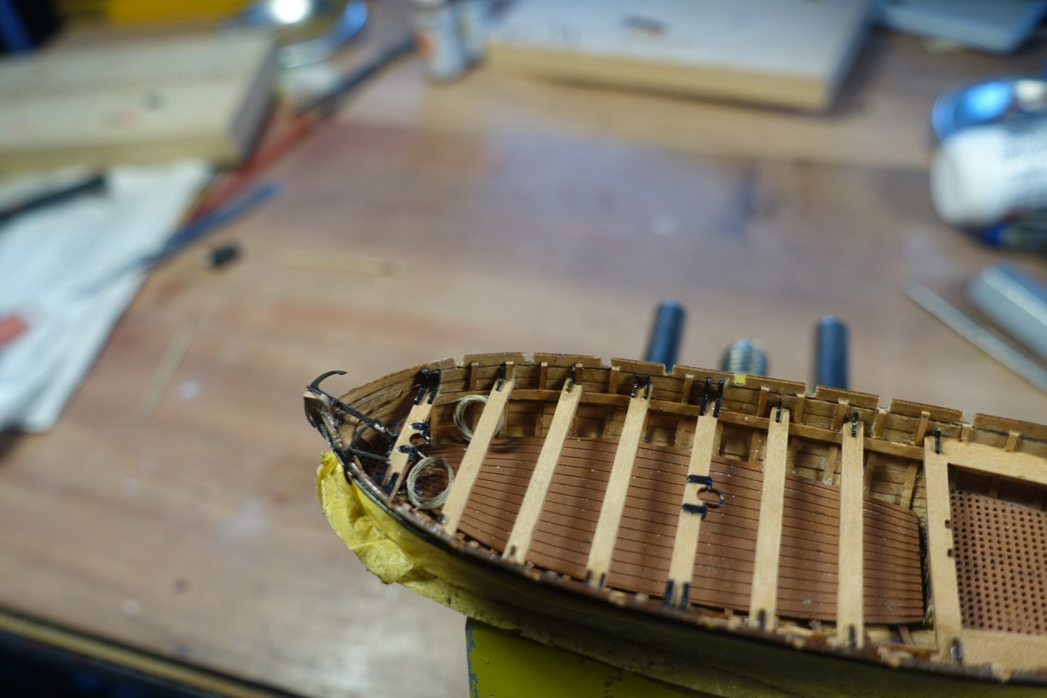
Thwarts
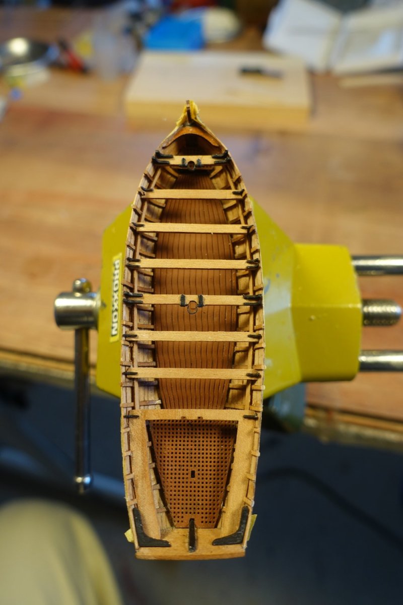
The thwarts were attached to the supports. A 1x7mm strip was used as a spacer between the thwarts. Where ribs met the middle of the thwarts, I removed the rib section above the supports. Later, knees have to be attached in the middle of the thwarts, which may come into conflict with the ribs.
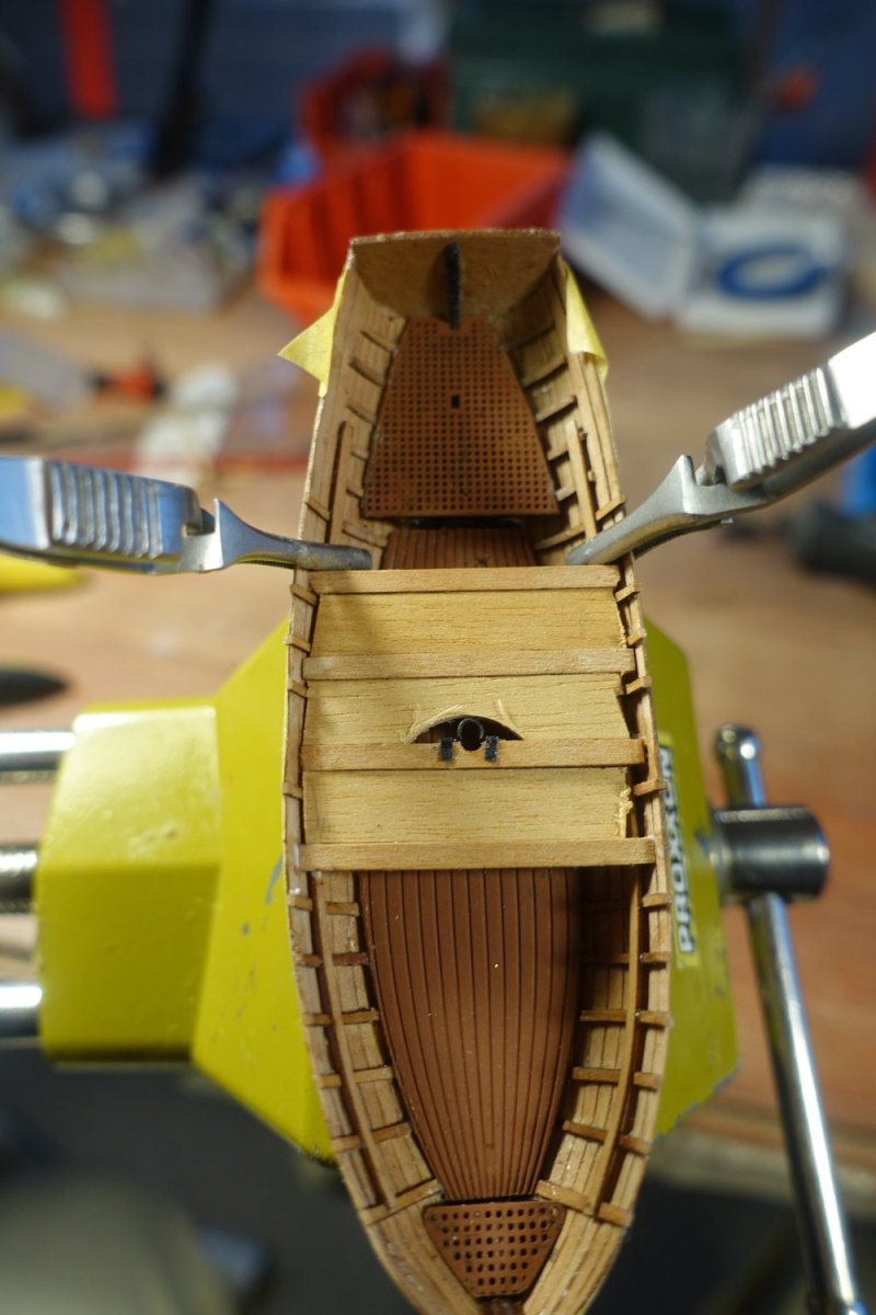
It is not shown on the plan, but Chris has prepared two mast brackets on the brass sheet. Unfortunately, one of them was swallowed by the carpet monster. Therefore I made a replacement from a brass bar of the brass sheet

Short pieces of ribs were glued to the rear seats.

The kit includes 20 knees for the thwarts. According to Chris' plan, however, 7x4 + 2, i.e. 30 knees, are required. Even if you only use two knees per thwart, that's still 16 knees, so there's not much in reserve. I painted the knees black at first.
The knees are attached. For the thwarts with the mast brackets, I used two knees on each side taken from the wood sheet of the pinasse (also part of the Sphinx kit). There are really quite few knees provided for the launch on the wood sheet. One Launch knee snapped off and I couldn't find it again.

- KARAVOKIRIS and bruce d
-
2
-
The thwarts were attached to the supports. A 1x7mm strip was used as a spacer between the thwarts. Where ribs met the middle of the thwarts, I removed the rib section above the supports. Later, knees have to be attached in the middle of the thwarts, which may come into conflict with the ribs.
It is not shown in the instructions and also not on the plan, but Chris has prepared two mast brackets on the brass sheet. Unfortunately, one of them was swallowed by the carpet monster. Therefore I made a replacement from a brass bar of the brass sheet.

Short pieces of ribs were glued to the rear seats.

The kit includes 20 knees for the thwarts. According to Chris' plan, however, 7x4 + 2, i.e. 30 knees, are required. Even if you only use two knees per thwart, that's still 16 knees, so there's not much in reserve. I painted the knees black at first.


The knees are attached. For the thwarts with the mast brackets, I used two knees on each side taken from the wood sheet of the pinasse (also part of the Sphinx kit). There are really quite few knees provided for the launch on the wood sheet. One Launch knee snapped off and I couldn't find it again.

- ccoyle, KARAVOKIRIS, chris watton and 2 others
-
5
-
20 hours ago, schooner said:
This is a great lesson on small boat kits whose ideas can be applied across many different kits and kit brands since they most of them follow the same basic construction sequence,
even lift-type hulls can still benefit from your ideas on detailing the interior.
Your techniques are very helpful since they do not require elaborate shop machines.
You have shown what planning, patience and attention to detail can accomplish - I just wish I had them.
I'll be saving this build log. Keep up the good work and thank you for taking the time to build it.
Thank you very much for the encouraging words. Once you get to grips with the peculiarities of these small boats, it really is a pleasure to build them.
Clark -
3 hours ago, allanyed said:
Clever way to have the risers (thwart supports strips) in the right location.
This one I want to remember. Thanks for sharing.
Allan
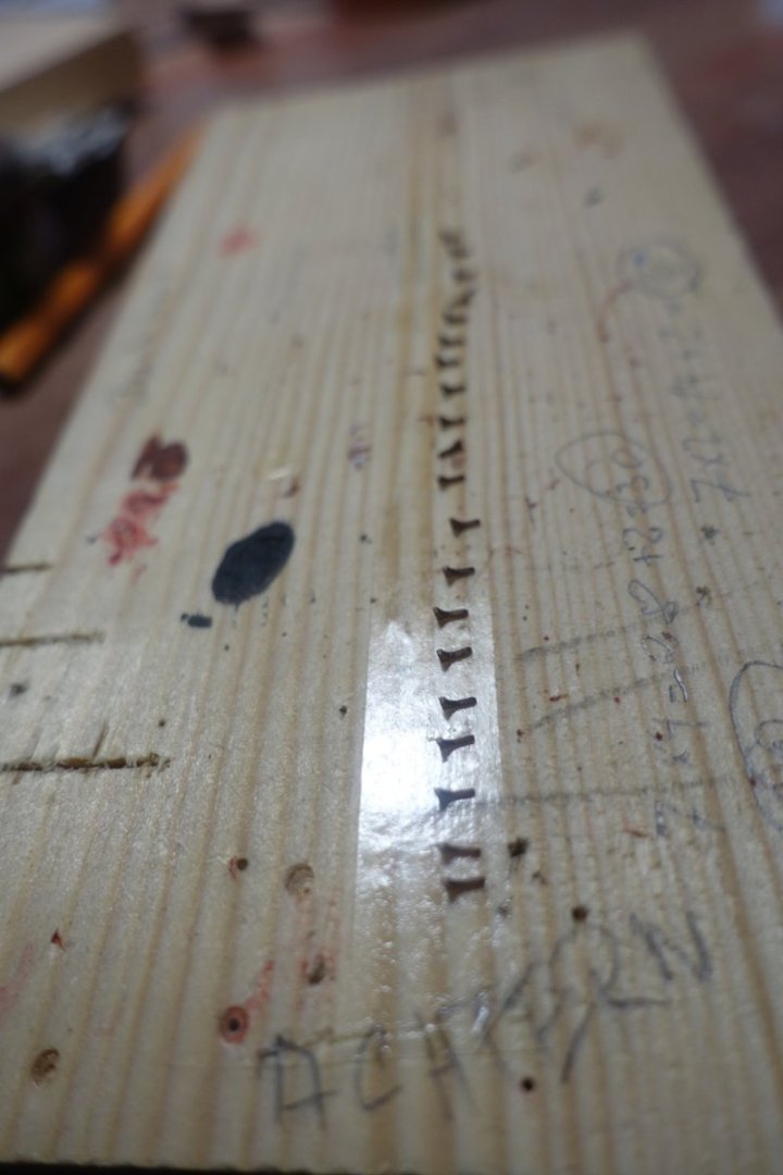
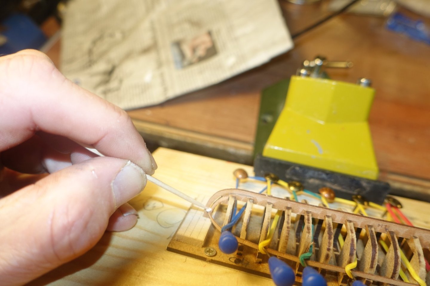
Thank you very much. I found the suggested method of pencil markings too imprecise, as the distance to the edge is difficult to mark.
Clark
-
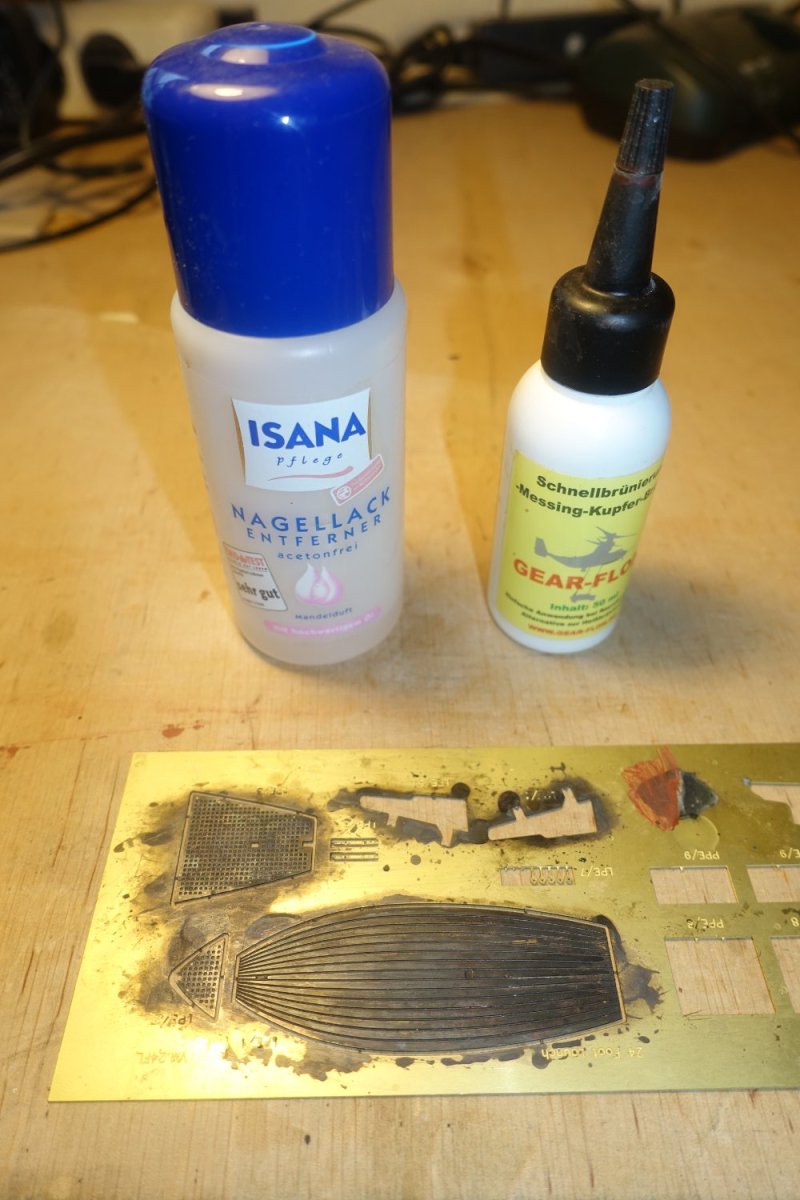
Just a short update: preparation of floor
The brass floor was first cleaned with nail polish remover and then treated with a blackening solution acting quickly. This type of solution does not produce such good results for blackening, but it does provide a base for subsequent painting.
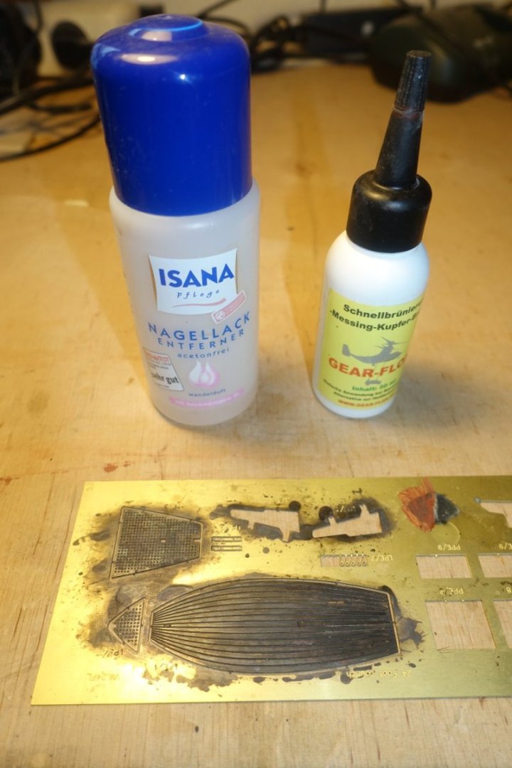
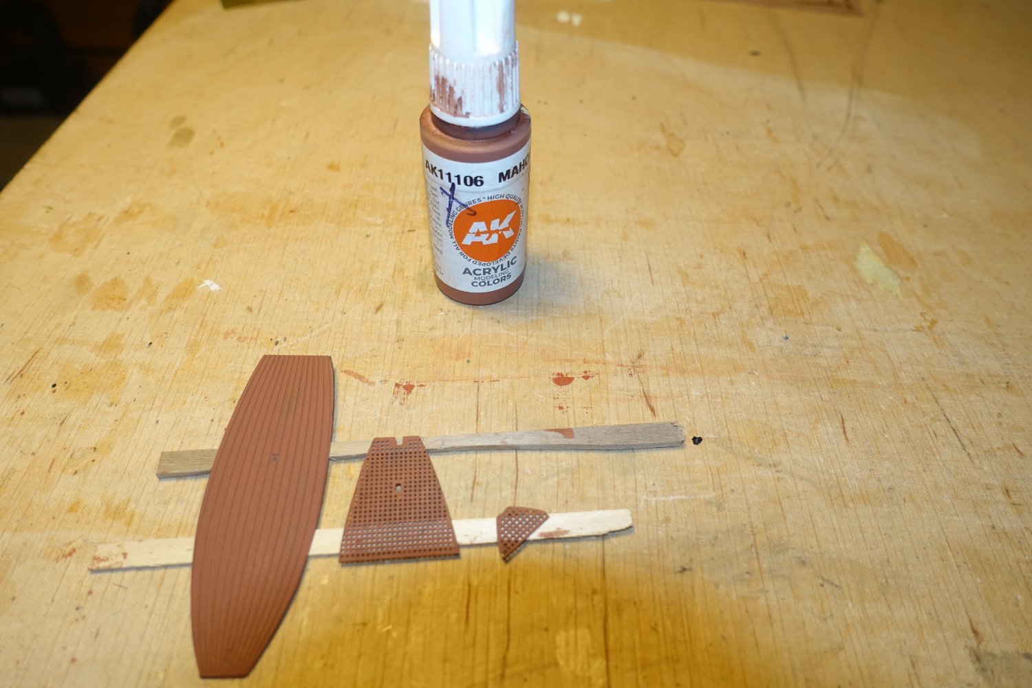
The "floorboards" were then painted mahogany.

- ccoyle, KARAVOKIRIS, bruce d and 1 other
-
4
-
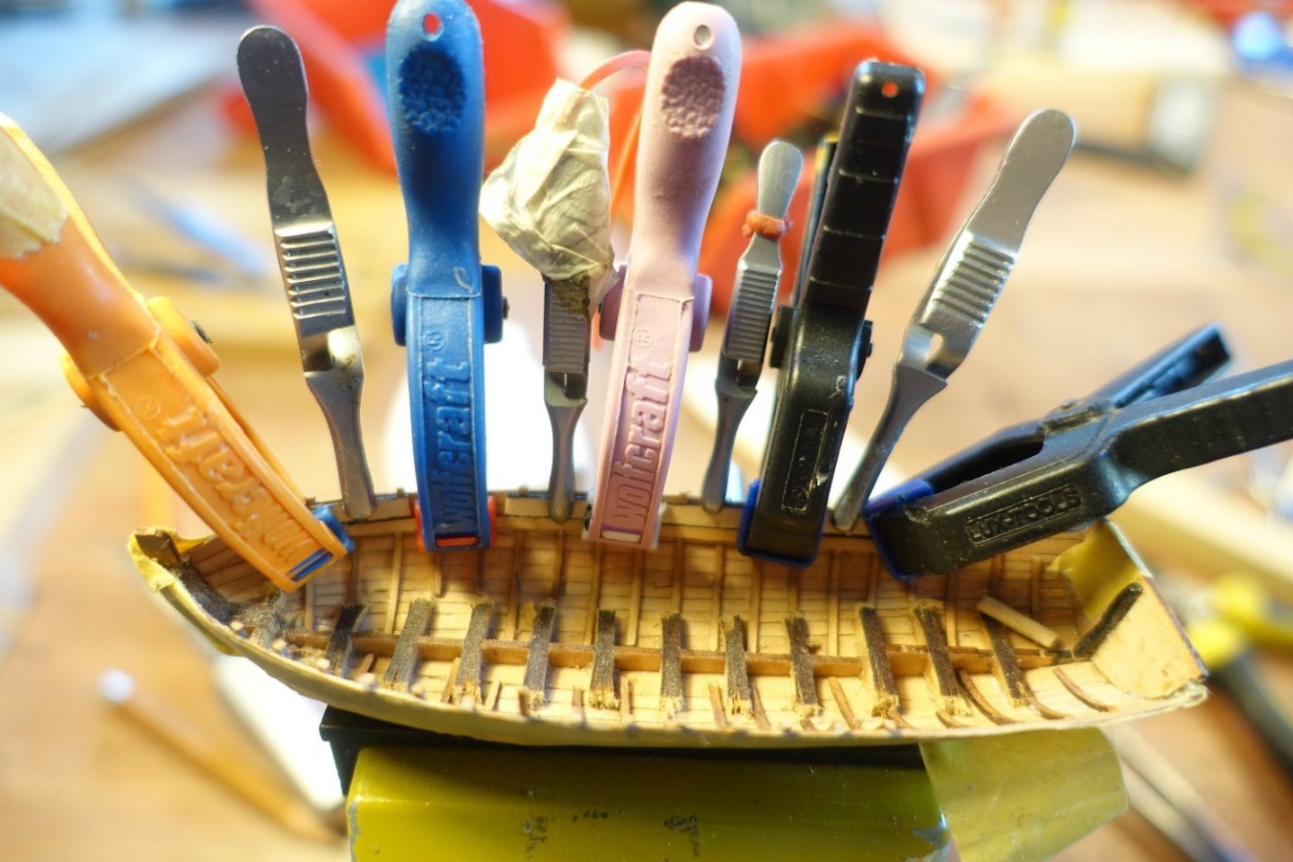
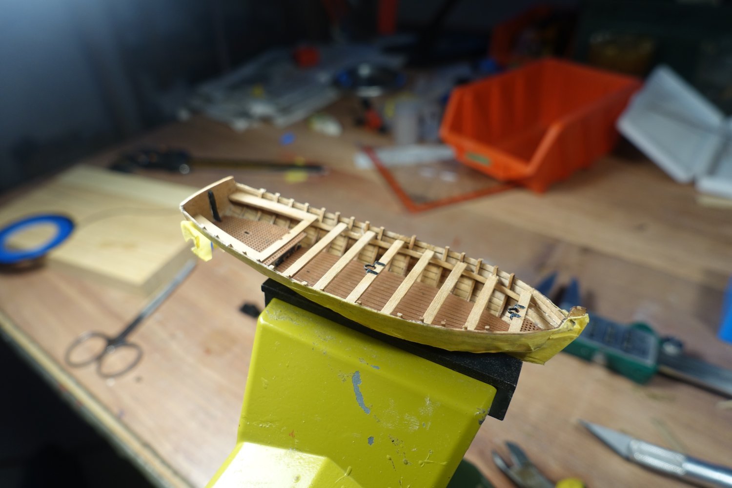
Ribs
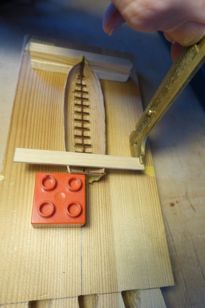
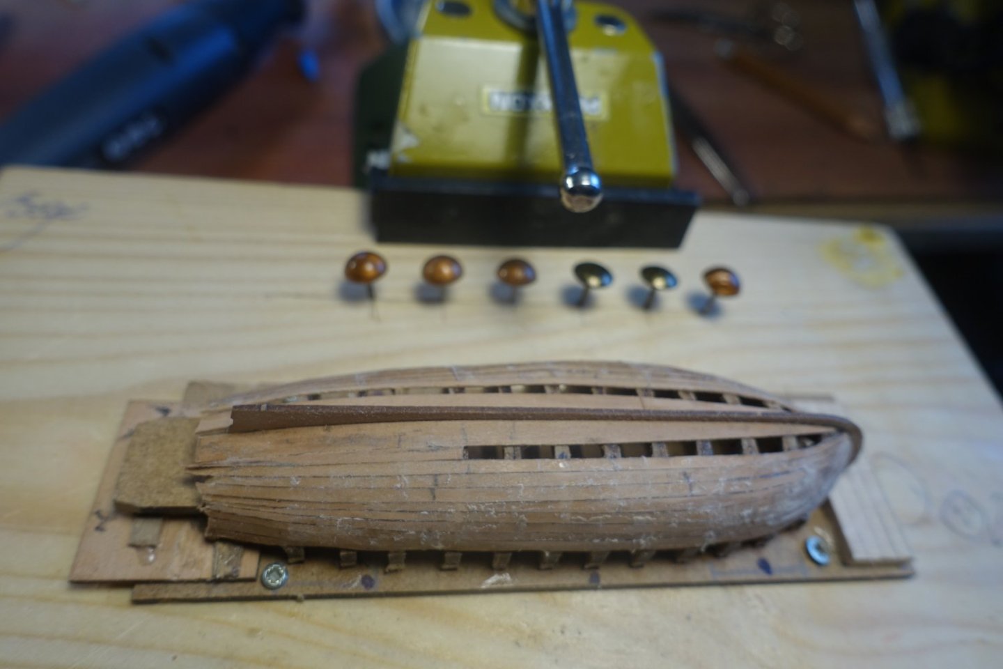
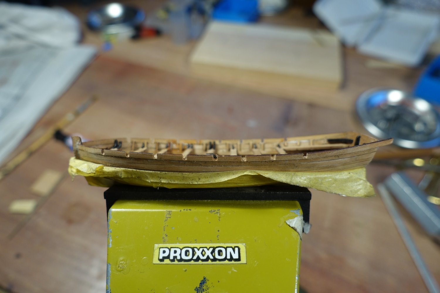
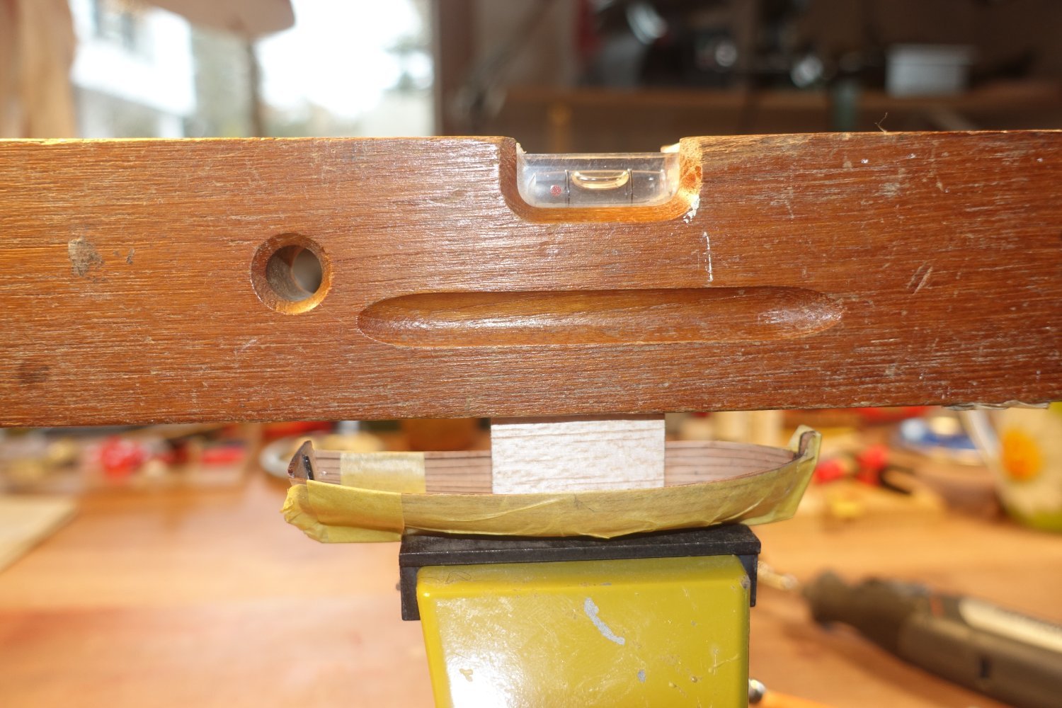
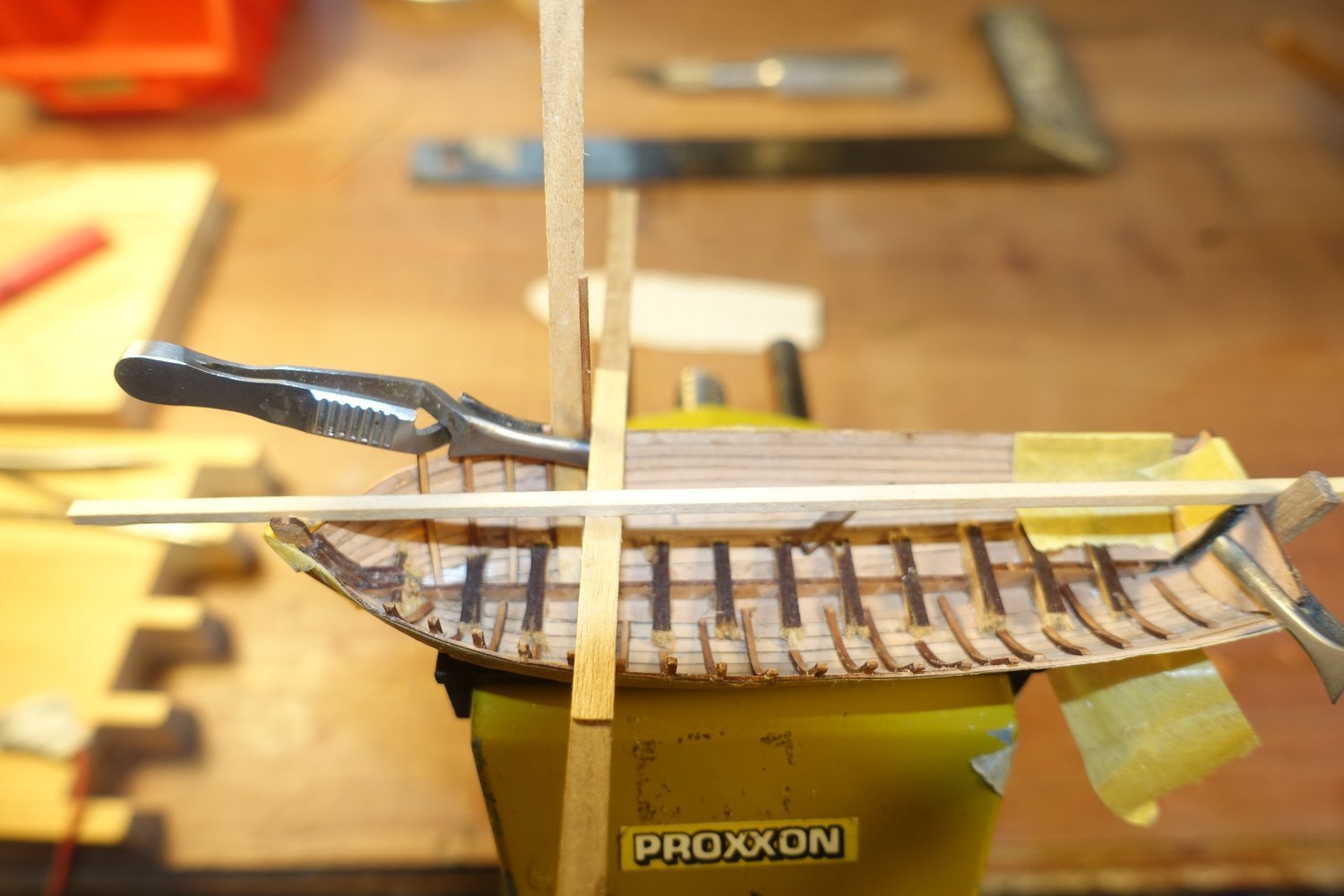
To level the starboard and port sides, I made a simple mini shipyard.

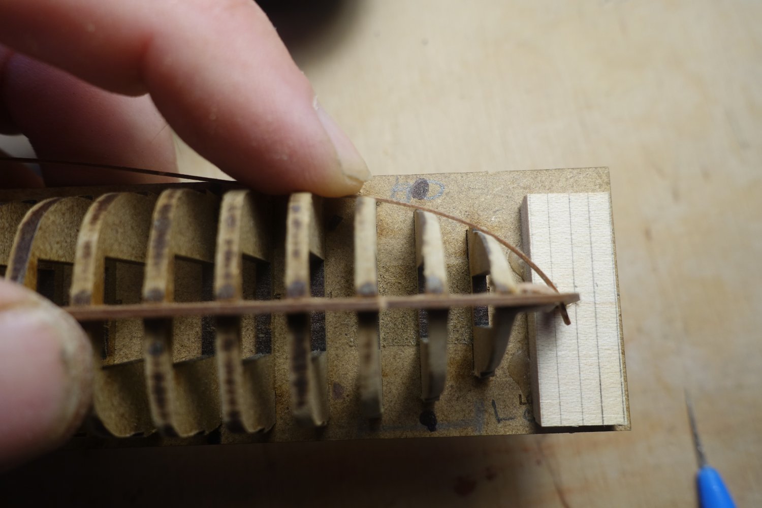
The launch is clamped in it, the vertical alignment is checked using a Duplo brick, which is brought into line with the sternpost. The distance to the bottom board is measured on both sides of the boat using a strip laid over the edges of the hull and the edge of the hull is sanded very lightly (!) if necessary. A minimal correction was only necessary in the stern area on the port side.
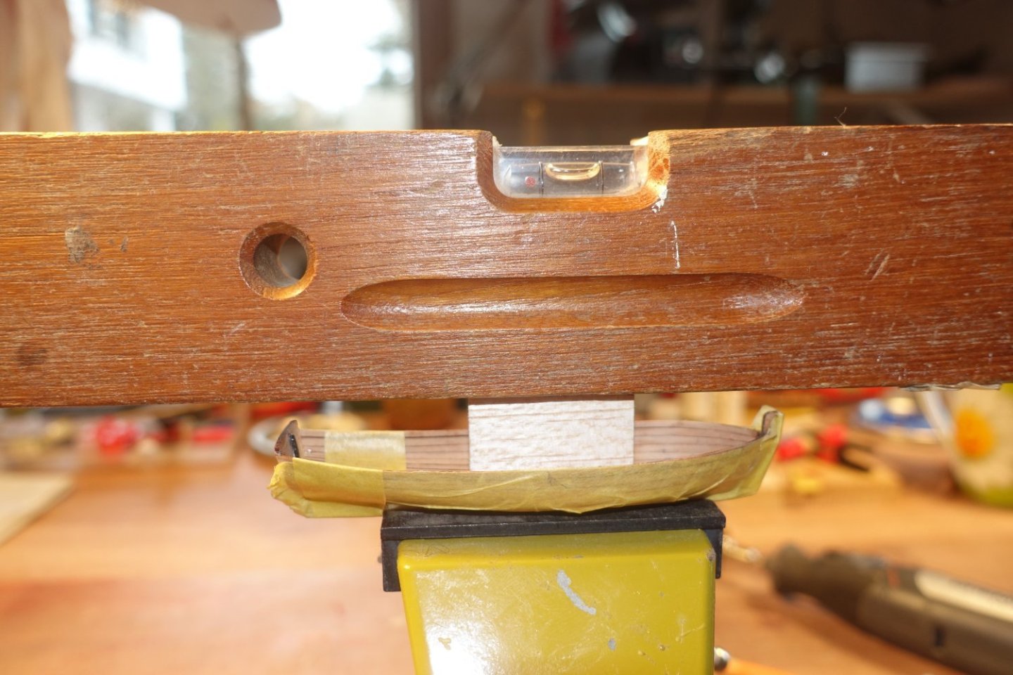
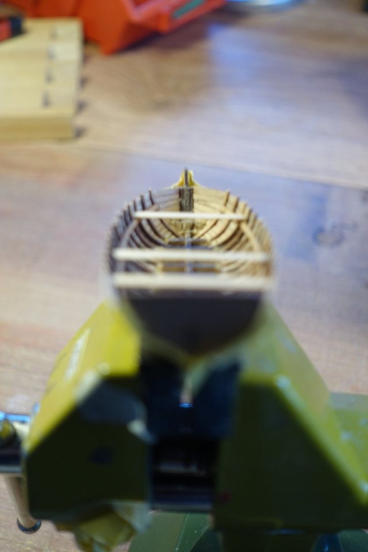
The boat was leveled along its longitudinal axis.
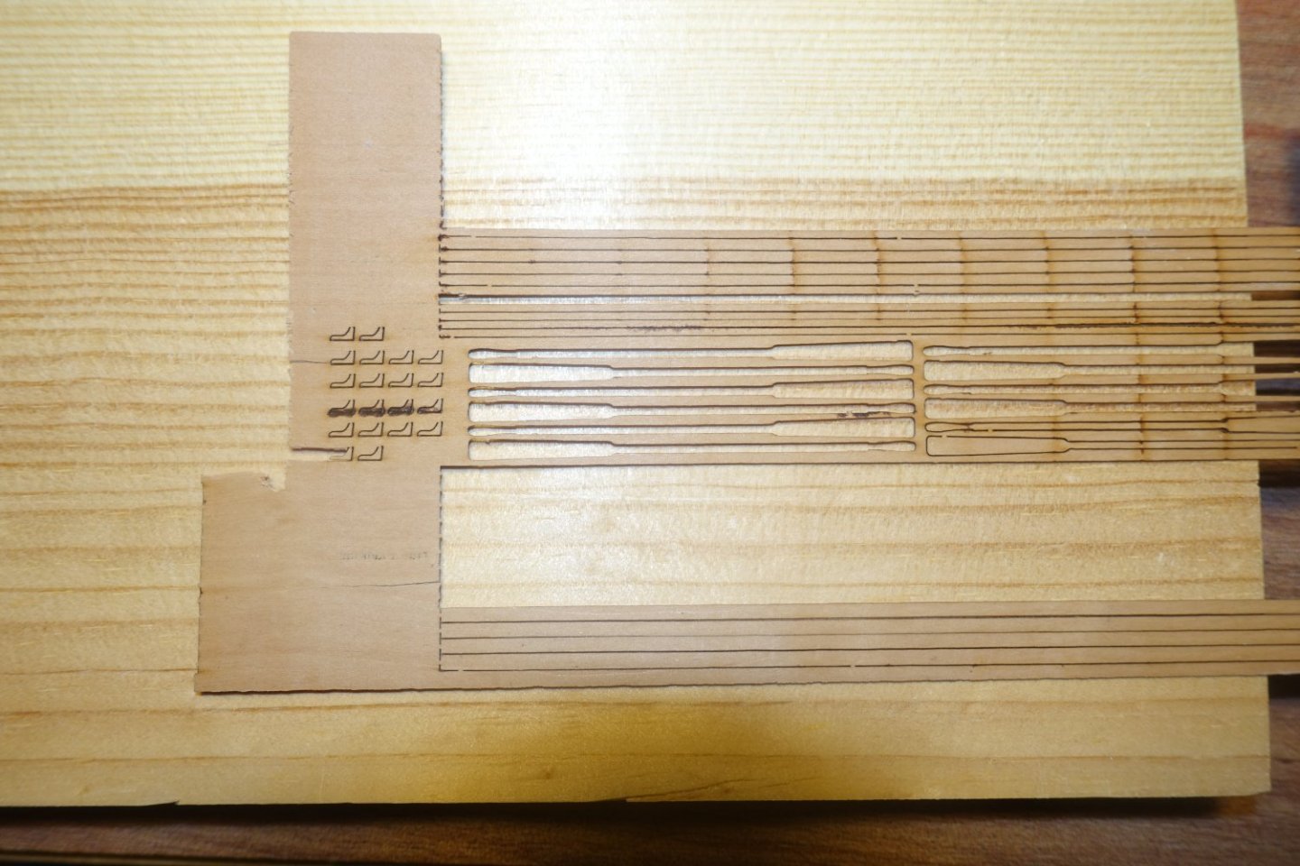
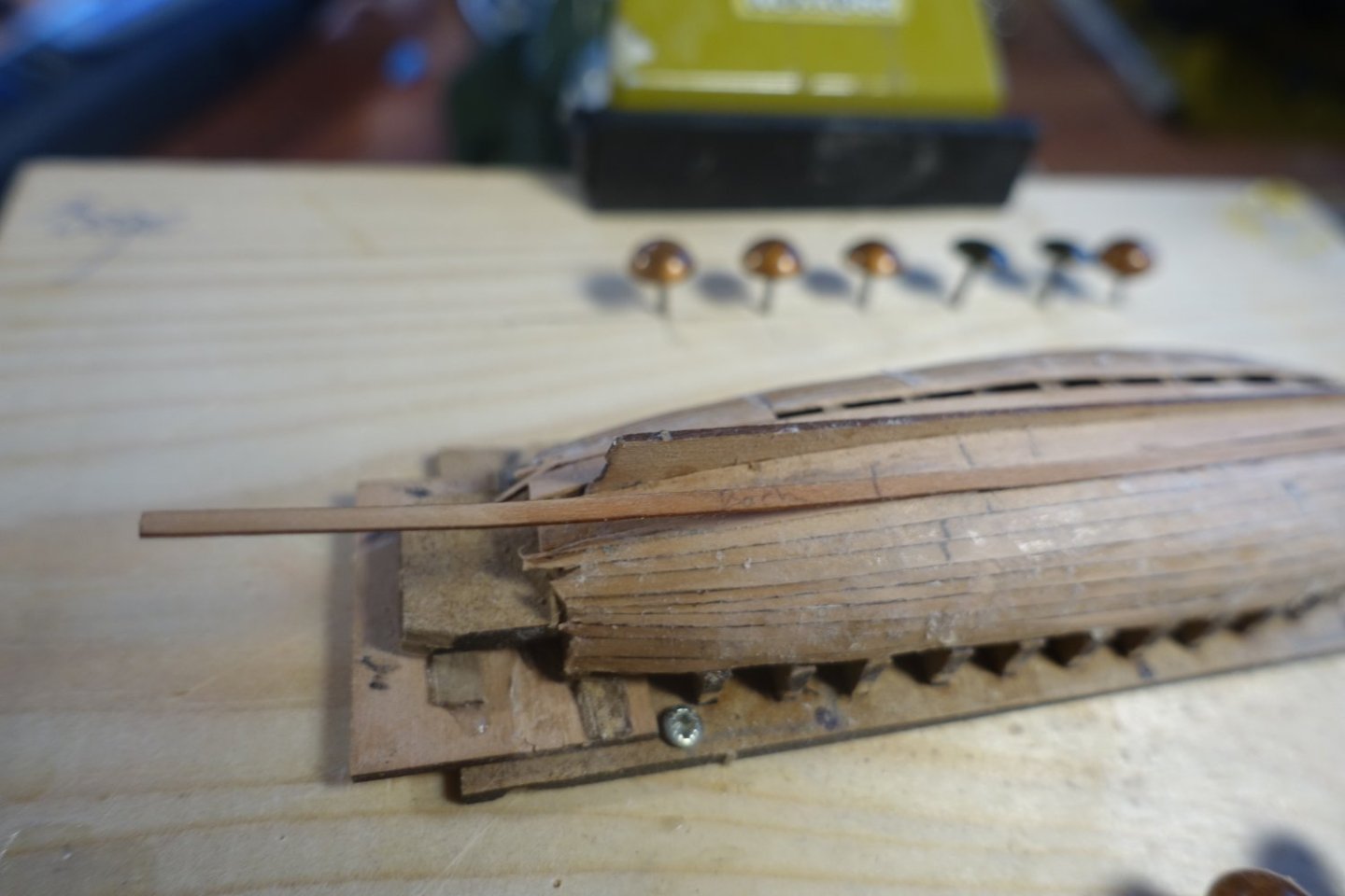
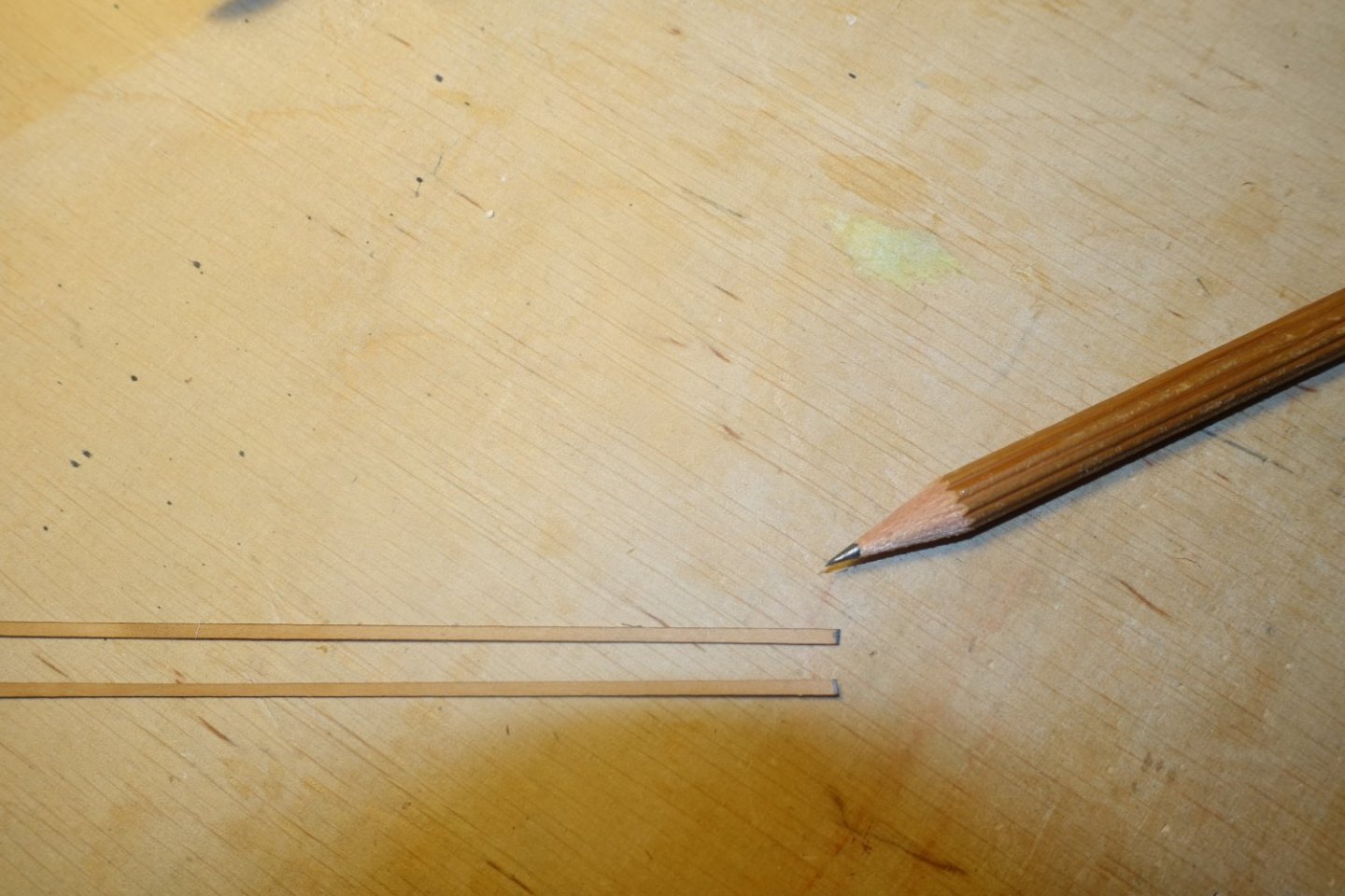
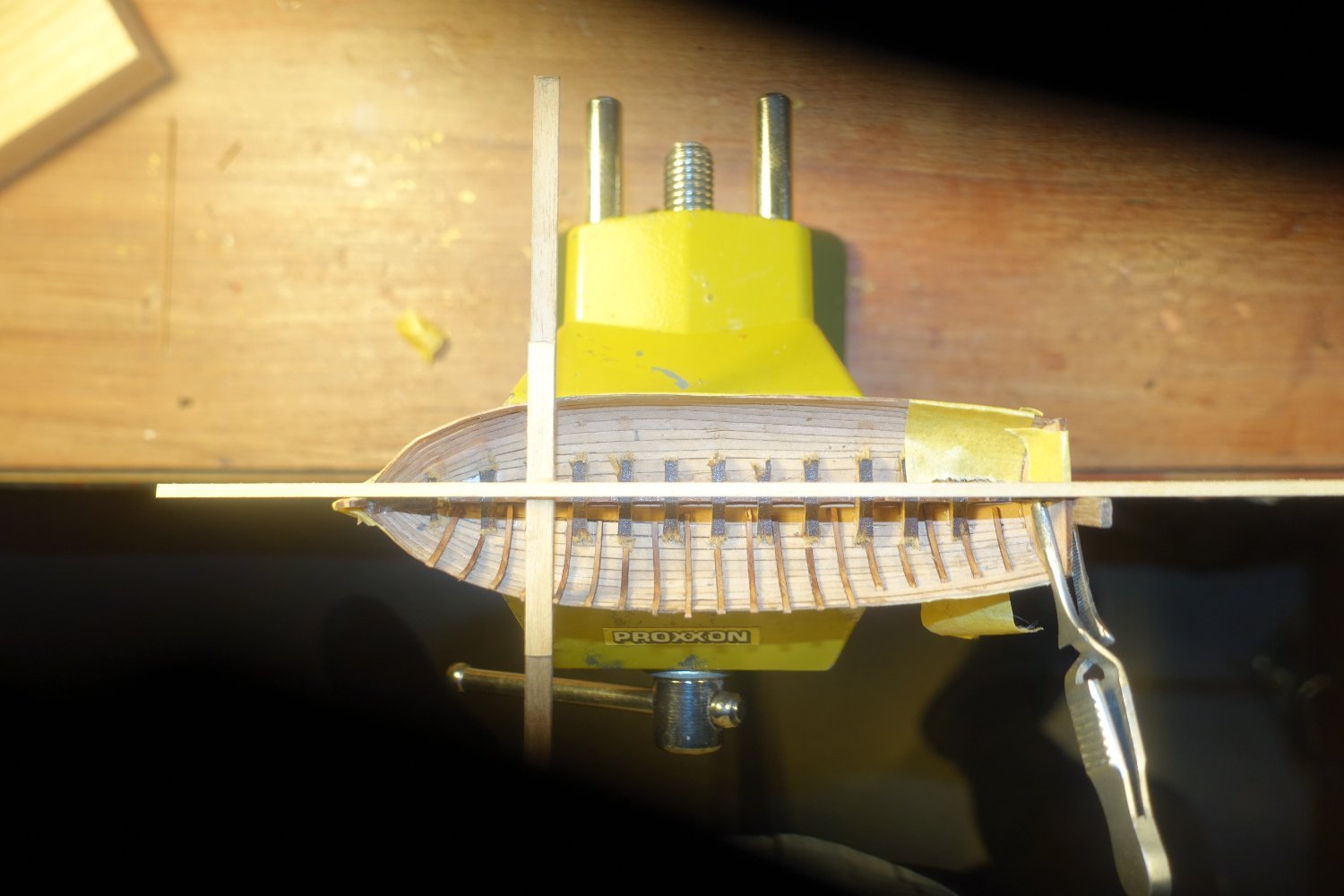
The ribs were bent at their ends using heat (top). I did the same with a 0.5x5 mm strip, which will later serve as a spacer between the ribs (bottom).

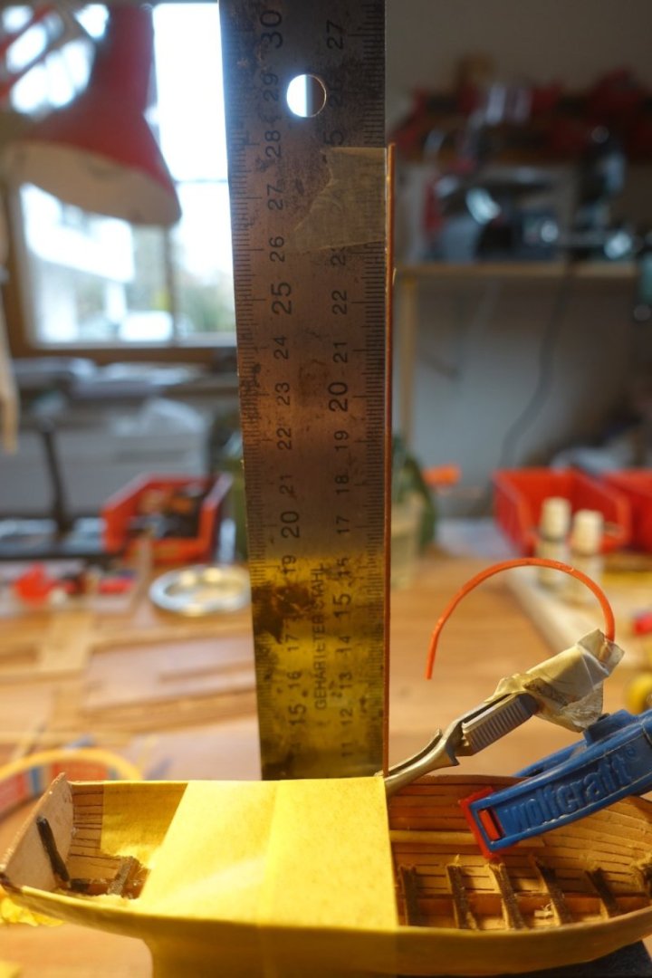
The first rib was attached with PVA, the vertical alignment was checked with the help of a right angle.
The previously bent 0.5x5mm strip was placed against the first rib and the second rib was then placed against the 0.5x5mm strip and glued to the hull.
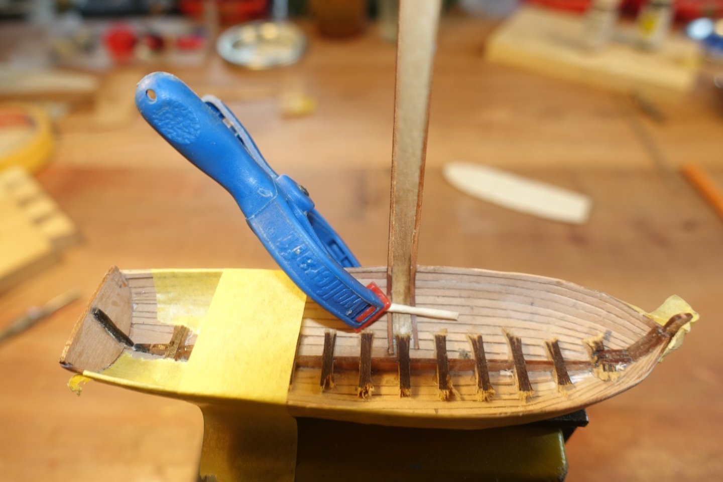
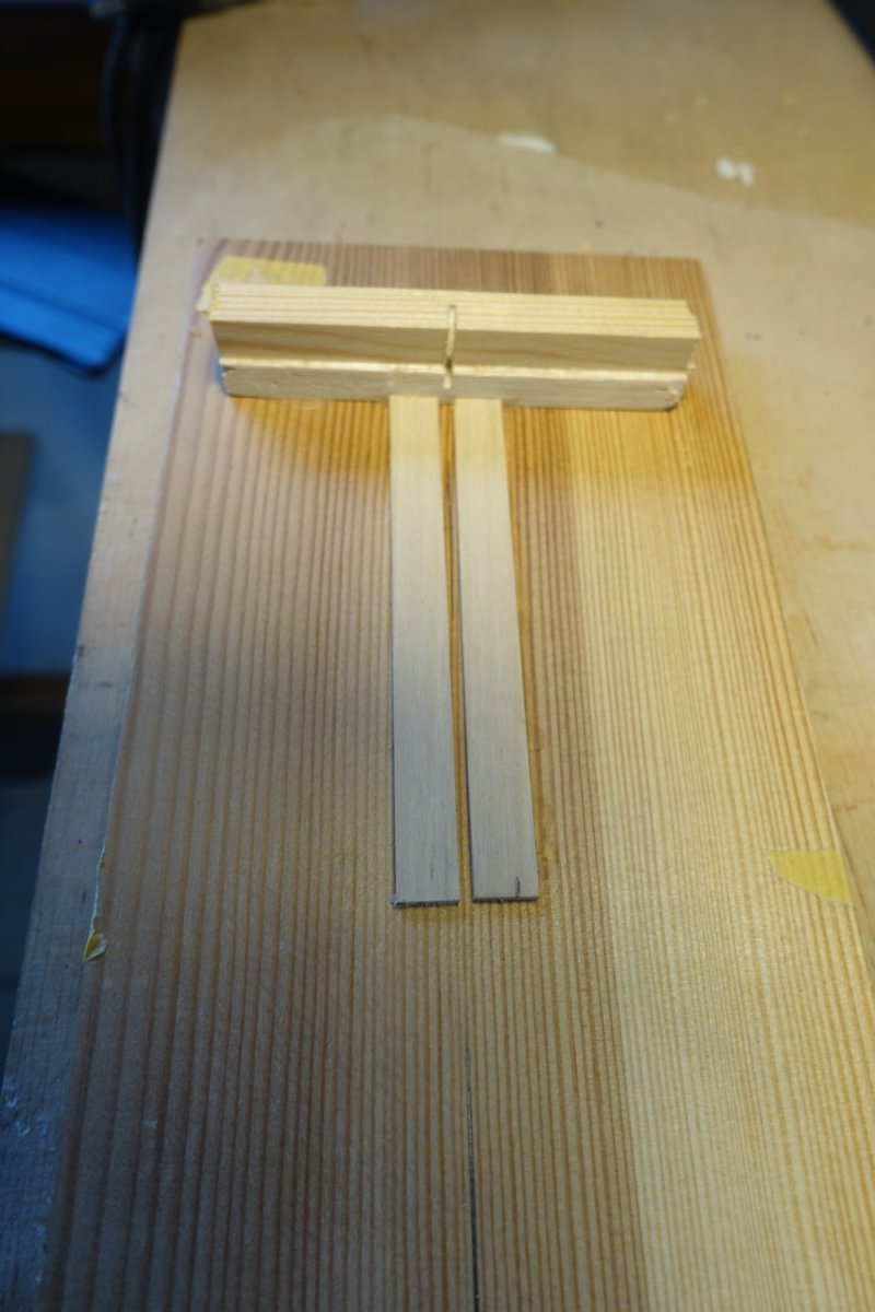
To align the ribs on the starboard side to the same position as those on the port side, I built myself a small alignment aid. A 2x5mm strip was glued at right angles to a smaller strip. This smaller strip can then be aligned with the stem and sternpost, while the 2x5mm strip is inserted between the protrusions of the ribs on the port side. I let the ribs on the port side protrude about 2-3 mm over the edge of the hull.


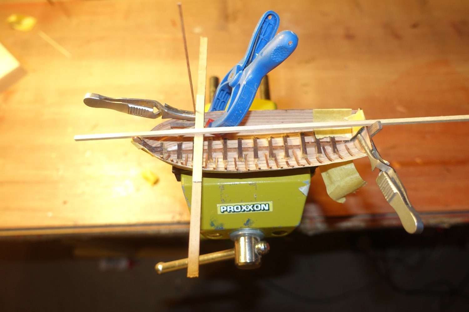
After all the ribs were attached, they were shortened. However, a 1mm overhang was left. The gunwale has to be fitted later. The overhang should serve to hold the gunwale in place.
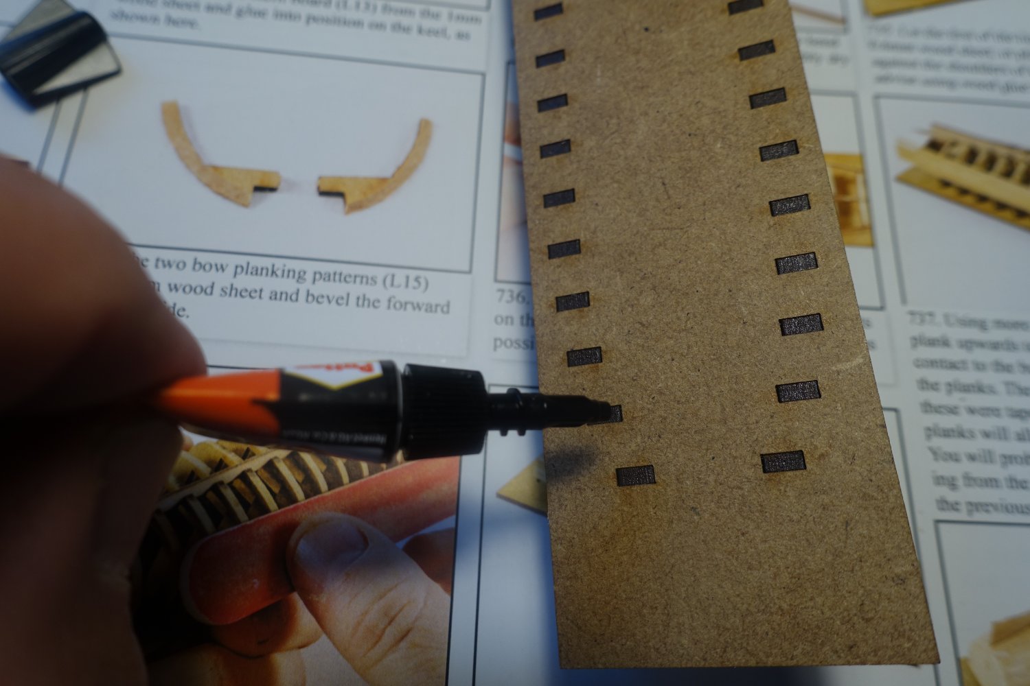
I used 3mm strips as spacers to attach the seat support strips at a distance of 3mm from the top of the bulwark.

Using these strips as a guide, the seat support was glued on.
After both supports had been fixed in this way, I checked again with strips laid across to see if the supports were correctly aligned.
- Blue Ensign, schooner, Glenn-UK and 2 others
-
5
-
6 hours ago, mugje said:
And be aware....when you are at the part of glueing it in place....don't put glue on the deck, but only at the false deck below. Because the PVA will moisture the wood causing it to swell a bit. This resulted in that the deck didn't fit anymore because I couldn't get it fast enough onto the false deck, and as a consequence...the deck became fixated in this swelled up size due to the glue that dryed. So I messed this up a bit
") Totally my own fault due to the inexperience working with thin sheets of wood. So maybe I can warn others to not make these mistakes
Totally my own fault due to the inexperience working with thin sheets of wood. So maybe I can warn others to not make these mistakes 
Even if you apply the PVA to the false deck, be careful with thinning. Let it dry slightly first. I made the same mistake.
Clark
-
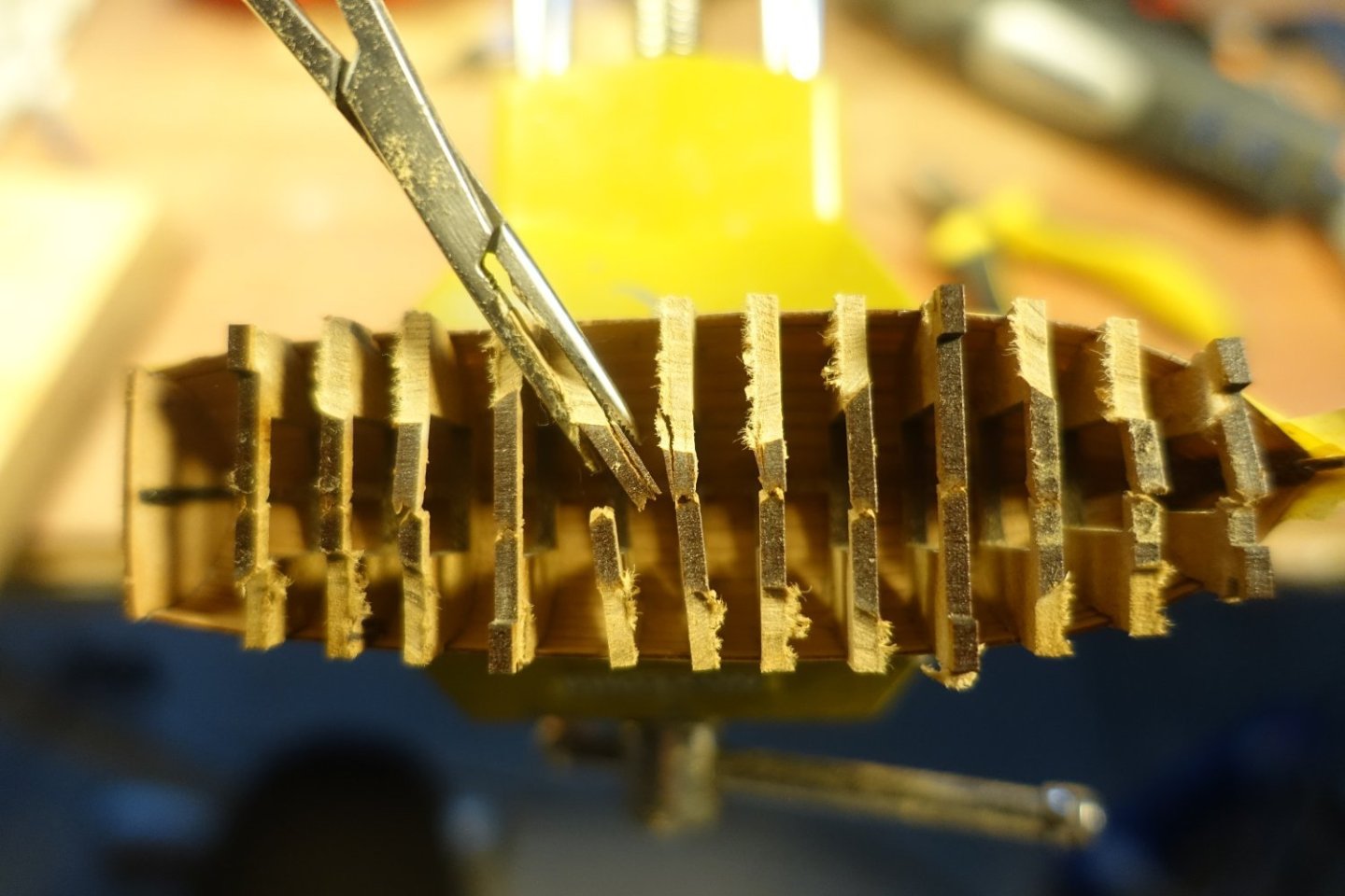
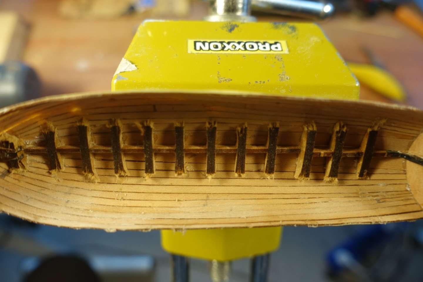
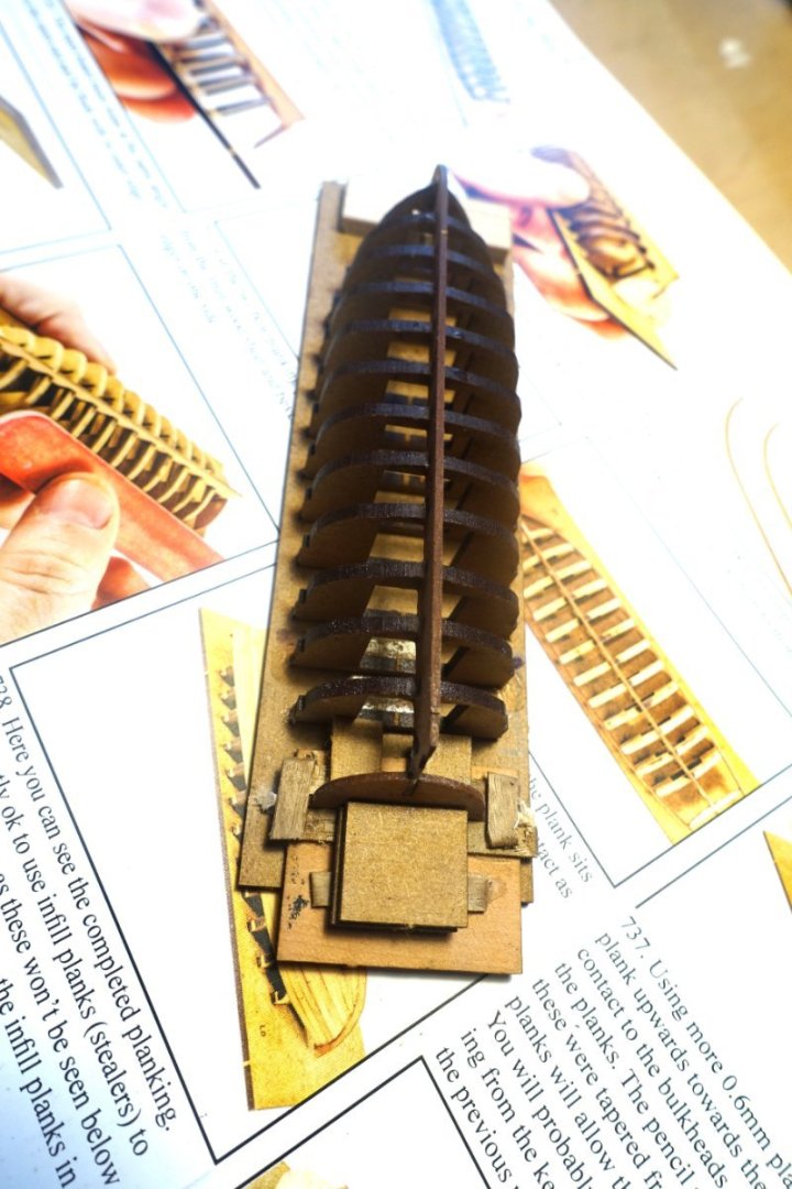
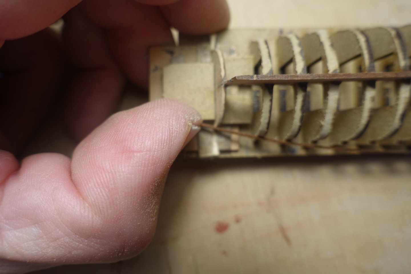
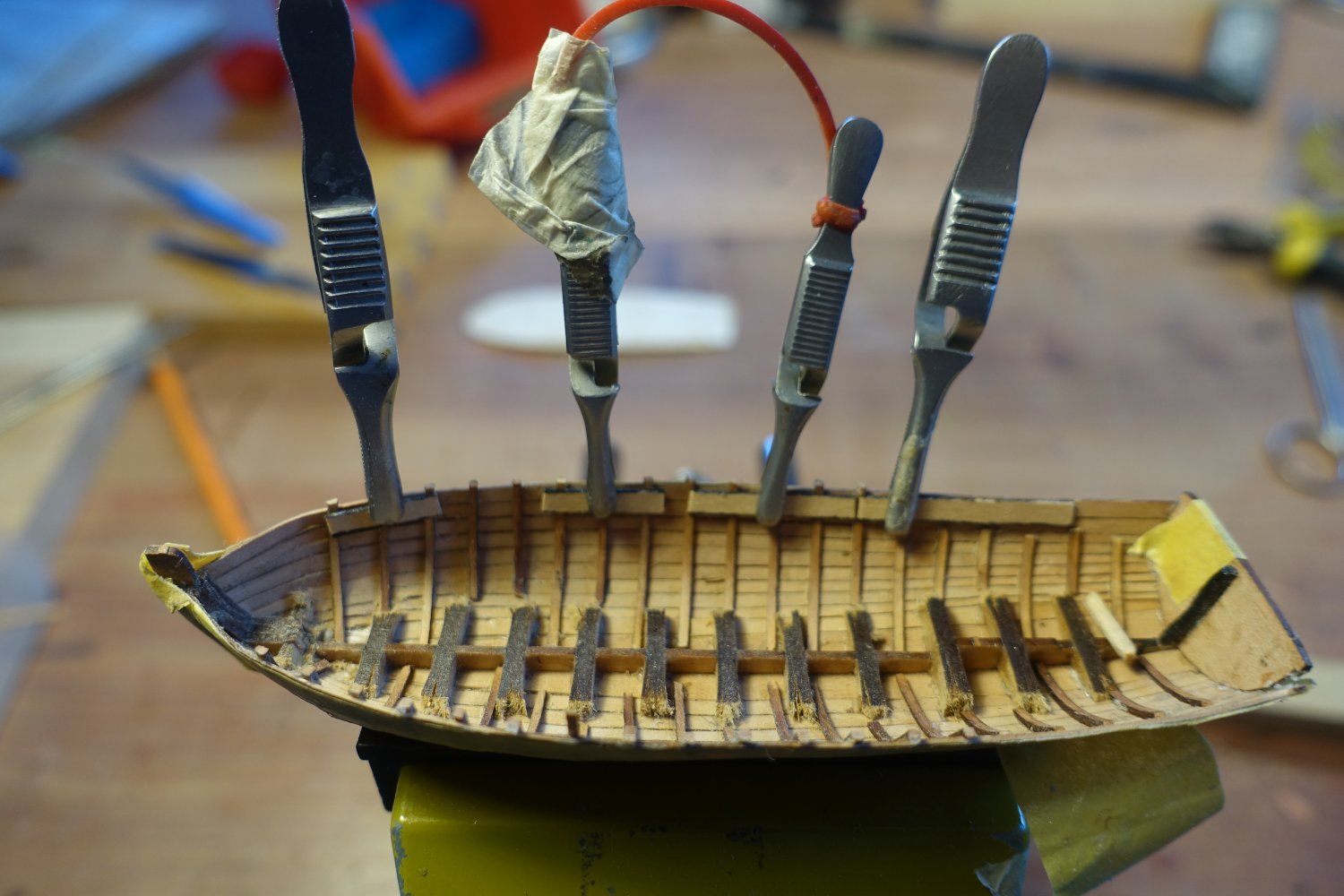
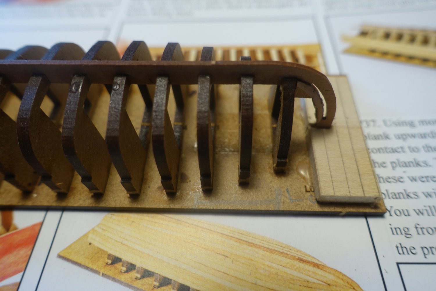
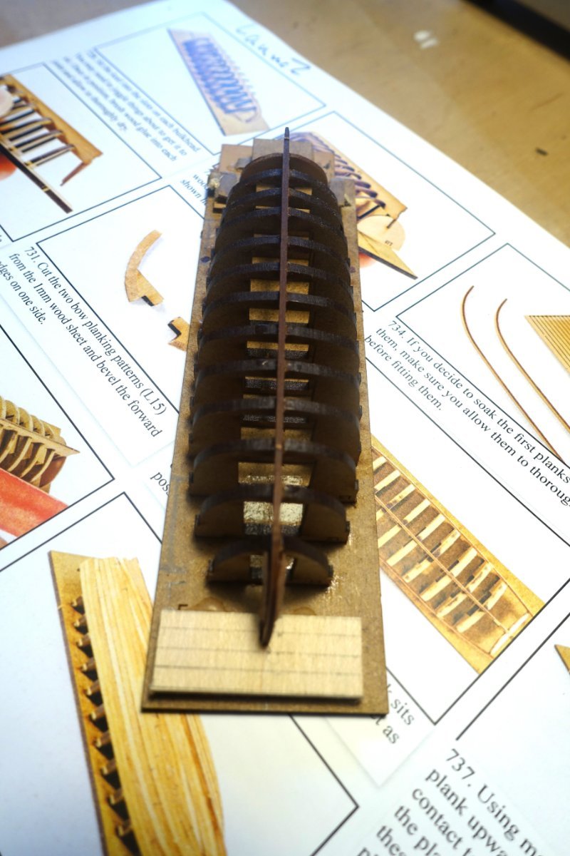
To remove the boat from its base, I first had to saw the frames that I had previously glued into the frame base.

After removing the frame base, the upper bars were cut through and then the frames were removed by turning them. As these were not glued to the planks, this was relatively easy.
There are very few traces of glueing visible inboard, only my pencil marks, which I forgot to remove before gluing the planks.
 .
.
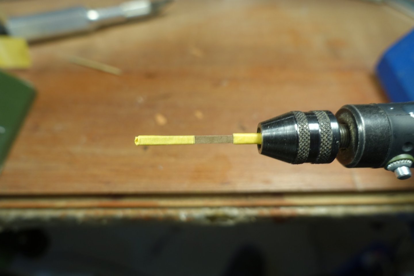
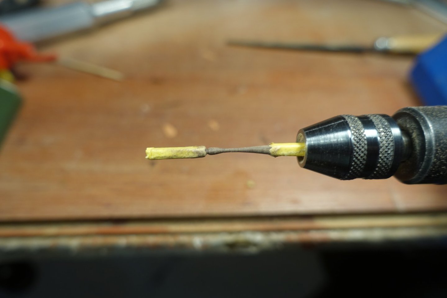
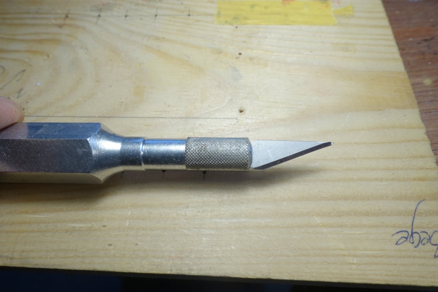
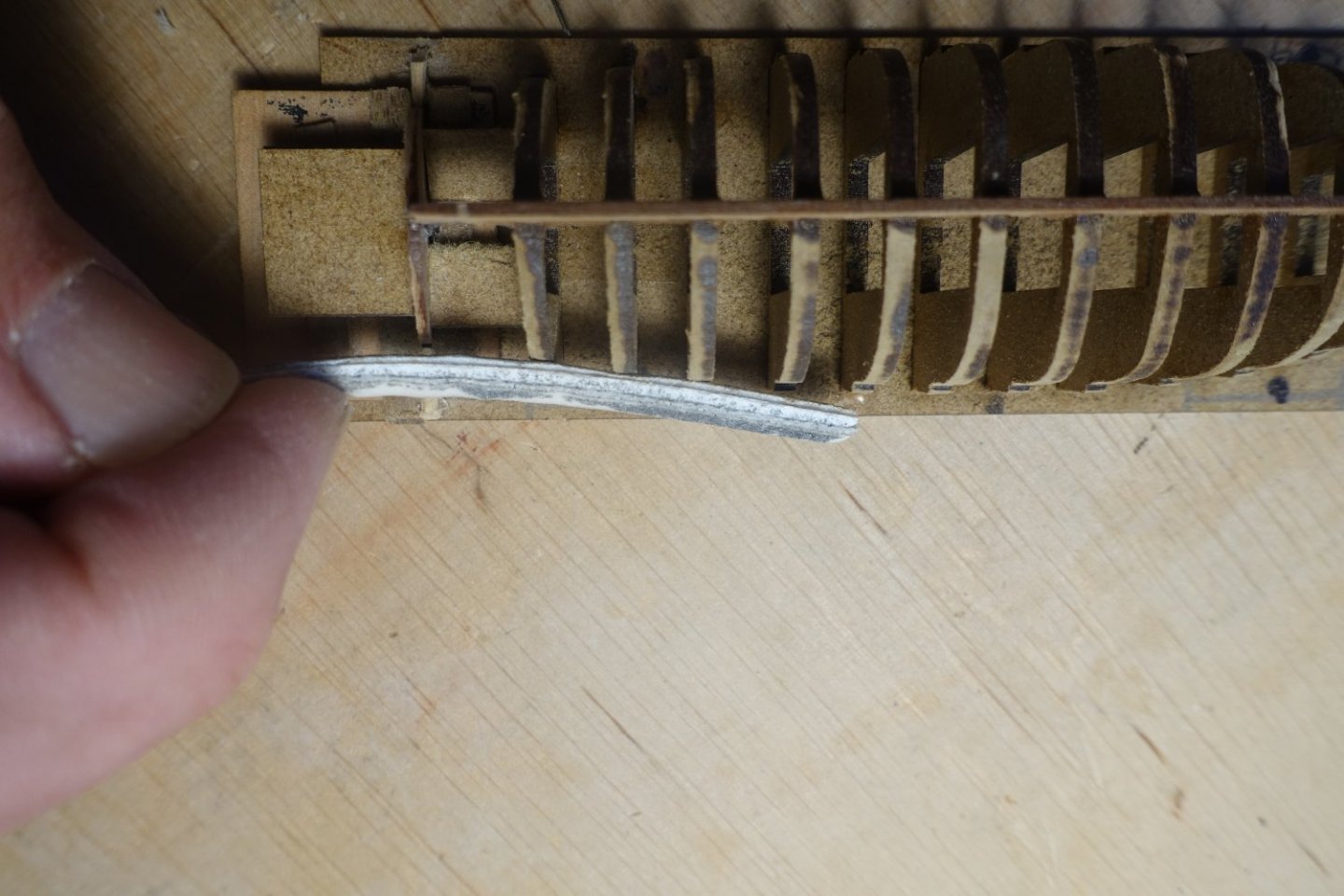
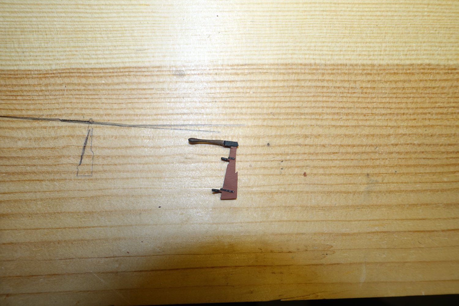
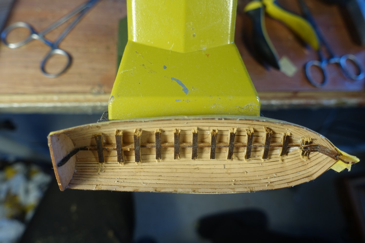
To remove the few traces of glue, I ground a mini chisel from a cutting blade (tip flattened and sharpened).
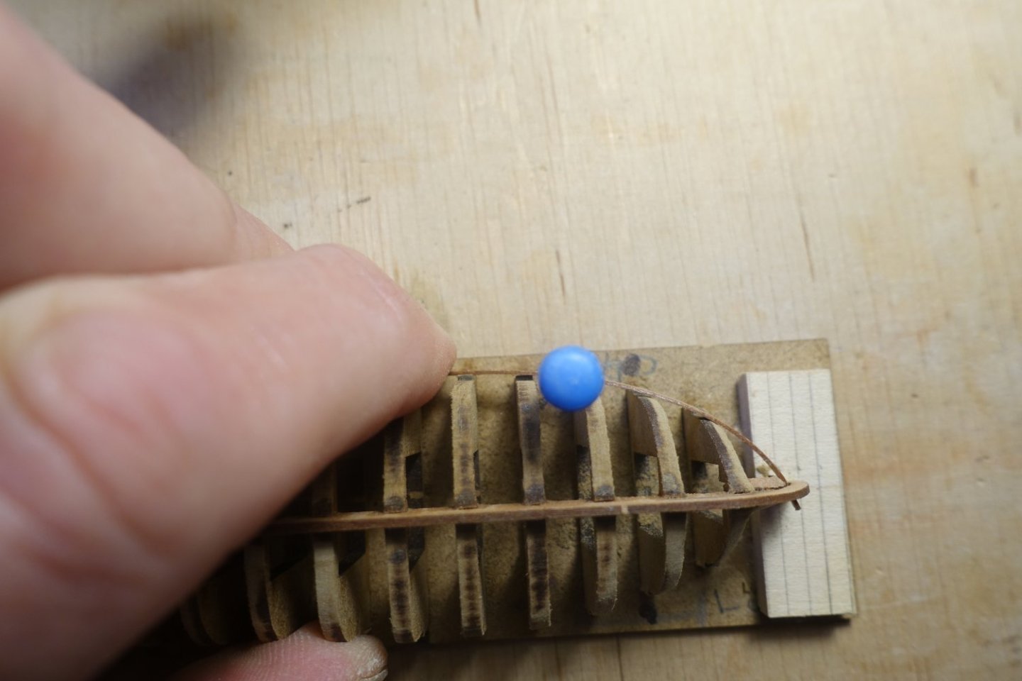
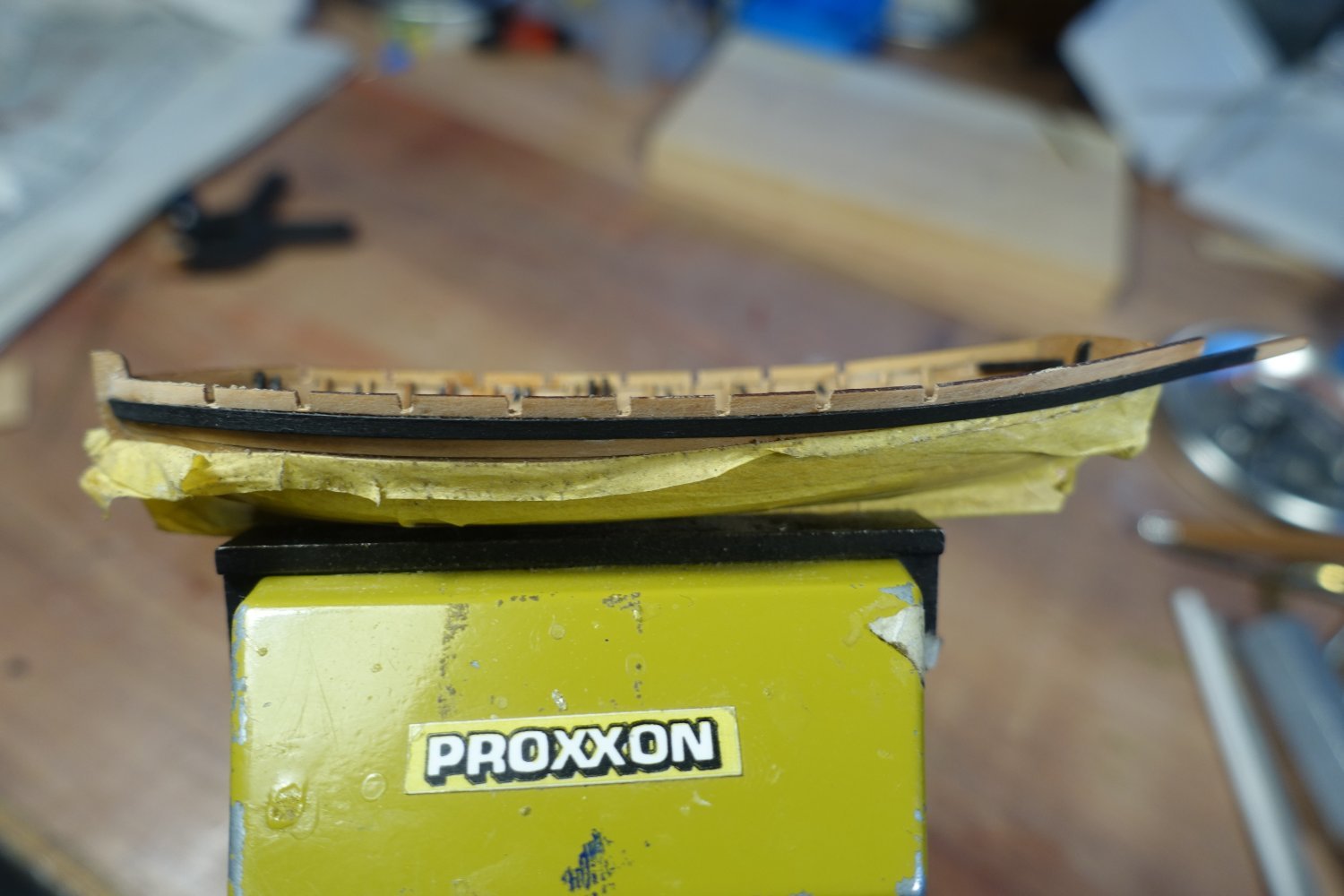
When looking at the edge of the hull, a slight indentation is noticeable on the port side at the height of the 4th frame from the rear.
The area was slightly moistened and straightened with the help of a clamp.

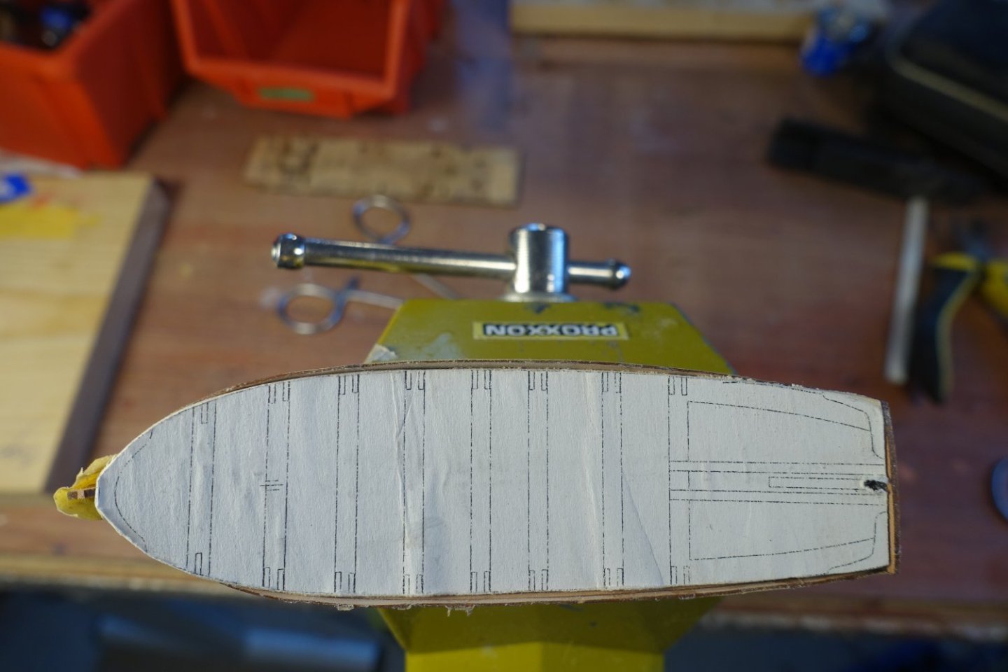
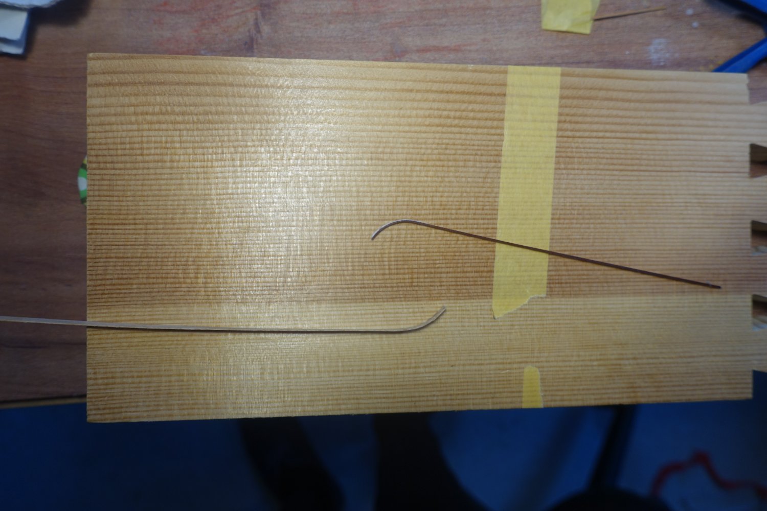
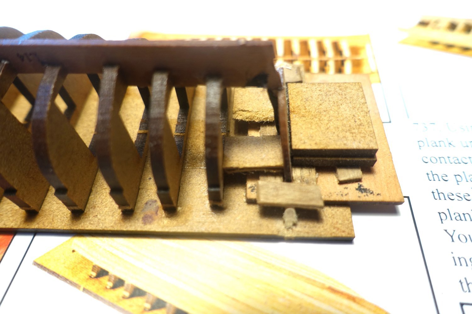
I cut a template (glued on a wood base) from the plan for further processing. This will later be used to place the ribs and the thwarts exactly.
- Paul Le Wol, Hartron, schooner and 5 others
-
8
-
18 hours ago, allanyed said:
Thanks for sharing your build!
Just a thought................. there is a build of the Portland 1770 that shows something I had not seen before and might serve well for all builds, kit or scratch. The location/breadth of the planks are laser marked on every bulkhead. It would probably be easier for kits as most are now laser cut whereas scratch is still more the old fashioned way. This should make it much easier for the builder to shape the breadth of the planks at each bulkhead so they are consistent from keel to top timber rather than having some planks very narrow and some very broad at any given bulkhead. https://modelshipworld.com/topic/34684-hms-portland-1770-by-scrubbyj427-148-4th-rate-50-gun-ship/
Allan
Thank you for stopping by.
The Portland is certainly an extremely ambitious project that will take the model builders further, also with the markings for the plank width. However, I'm not sure whether this makes sense and works with the small MDF frames of Chris' boats.
Clark -
4 minutes ago, Blue Ensign said:
That looks an excellent build of these tricky little boat hulls. 👍
B.E.
You've described the construction very well. I think you experience all the ups and downs with the small boats as you do with the larger ships.
-
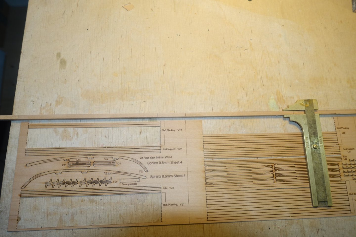
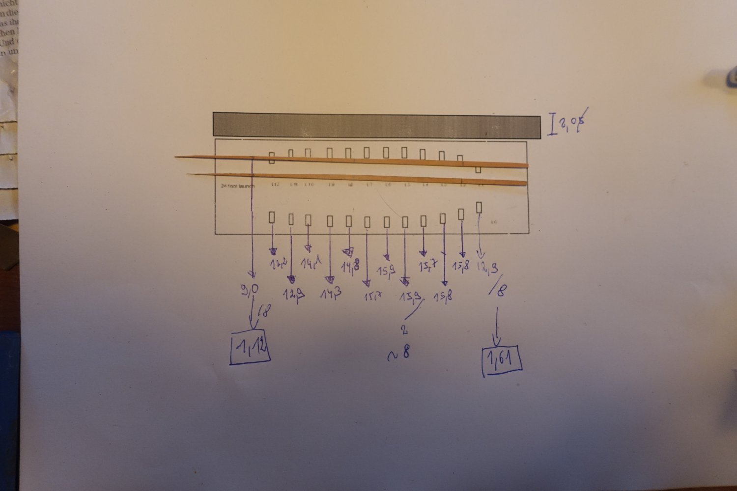
To get a rough idea of the taper still required for the planks, I measured the distance between the garboard strake and the upper planks and transferred it to the plan of the frame board.

I then proceeded in the same way as for a larger ship. The largest width in the middle of the hull is 15.9 mm, i.e. with a plank width of 2 mm, 8 planks are required here. Accordingly, a plank width in the area of the first bulkhead of 12.8/8=1.61 mm and a plank width in the area of the transom of 9.0/8=1.12(5) mm. Even if the figures seem accurate, they will certainly have to be adjusted later. In any case, I cut the next two pairs of planks according to these figures.
Only the last plank up to the garboard strake is now missing. You could try to take exact measurements of the gap. However, I have found that it is best to adjust by eye. I then adjusted this plank position in two sections (stern and bow).
The hull is still littered with white crumbs. These are the remains of the dried PVA glue. It looks bad, but will disappear completely when sanded.
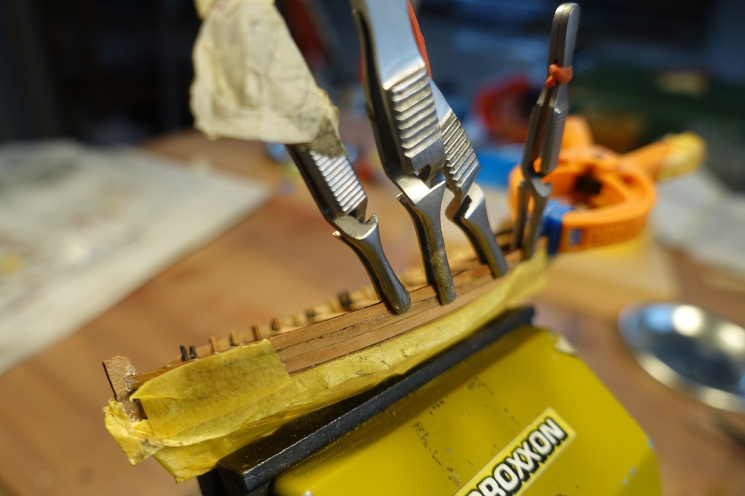
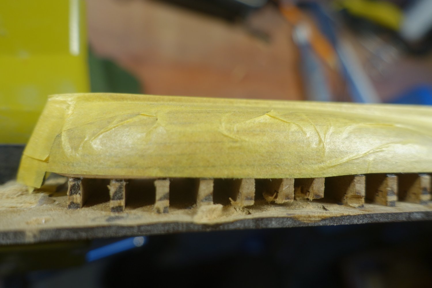
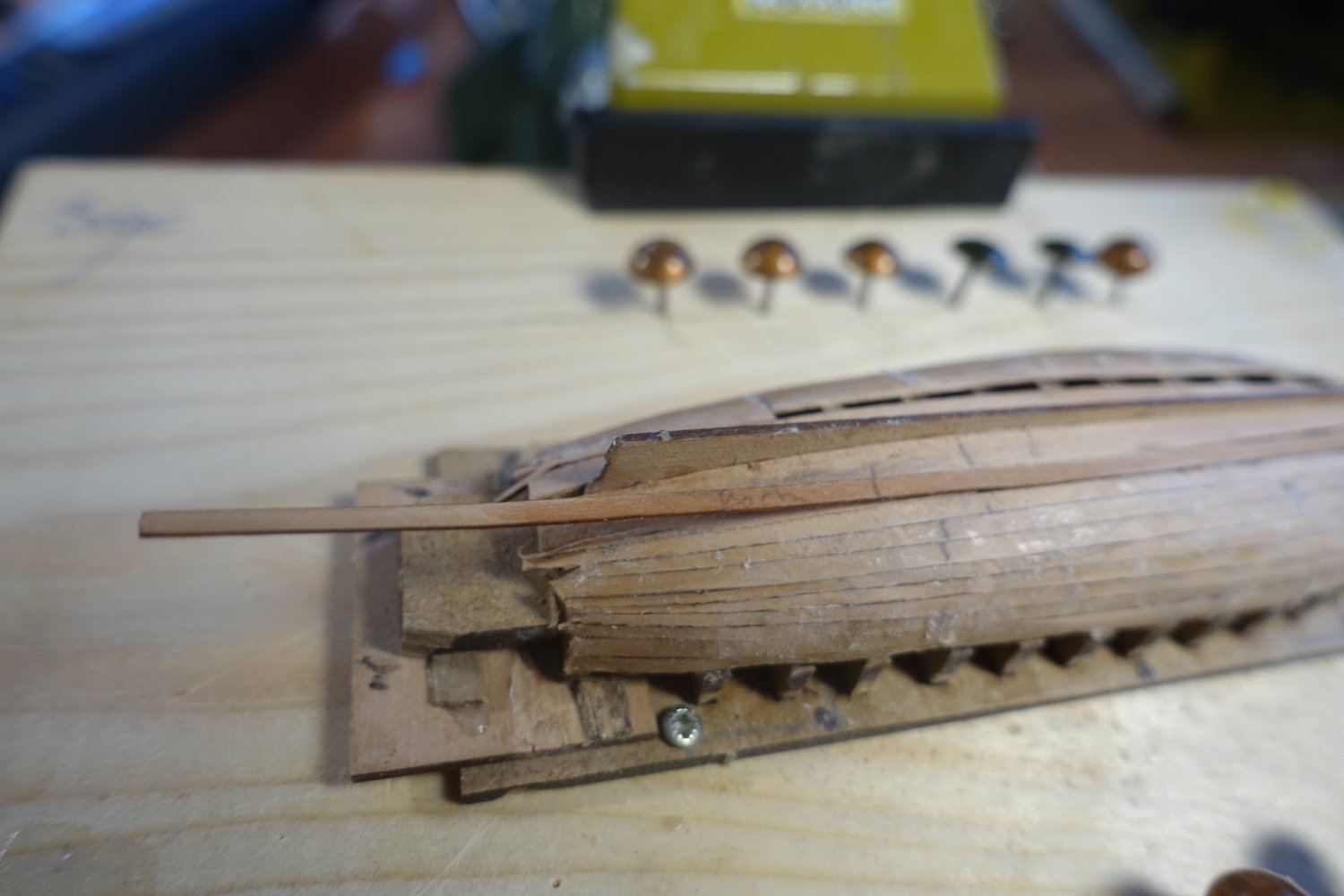
Next, I cut off or sanded the protrusions at the stern. To prevent the fine planks from splintering during sanding, I covered them with masking tape.
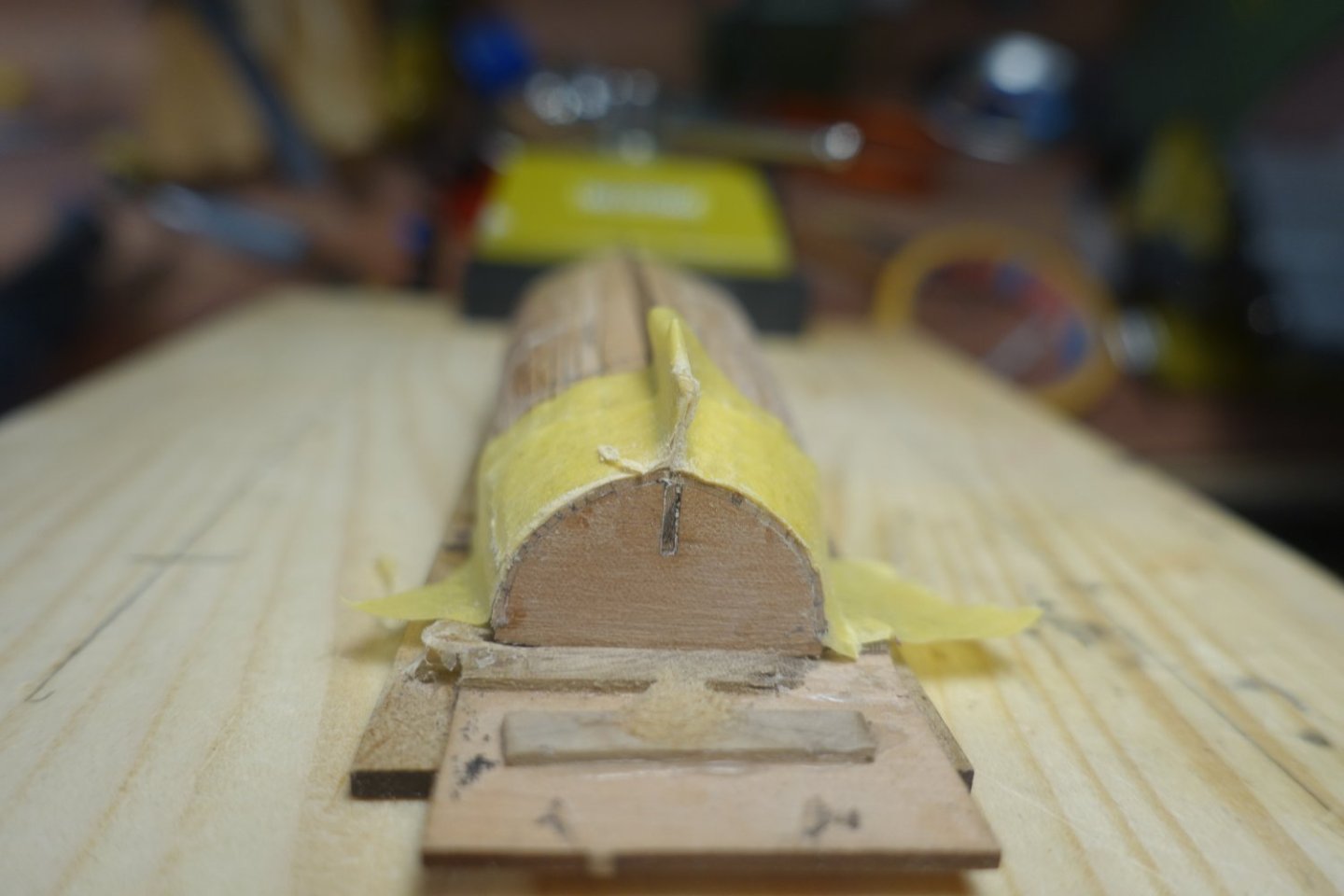
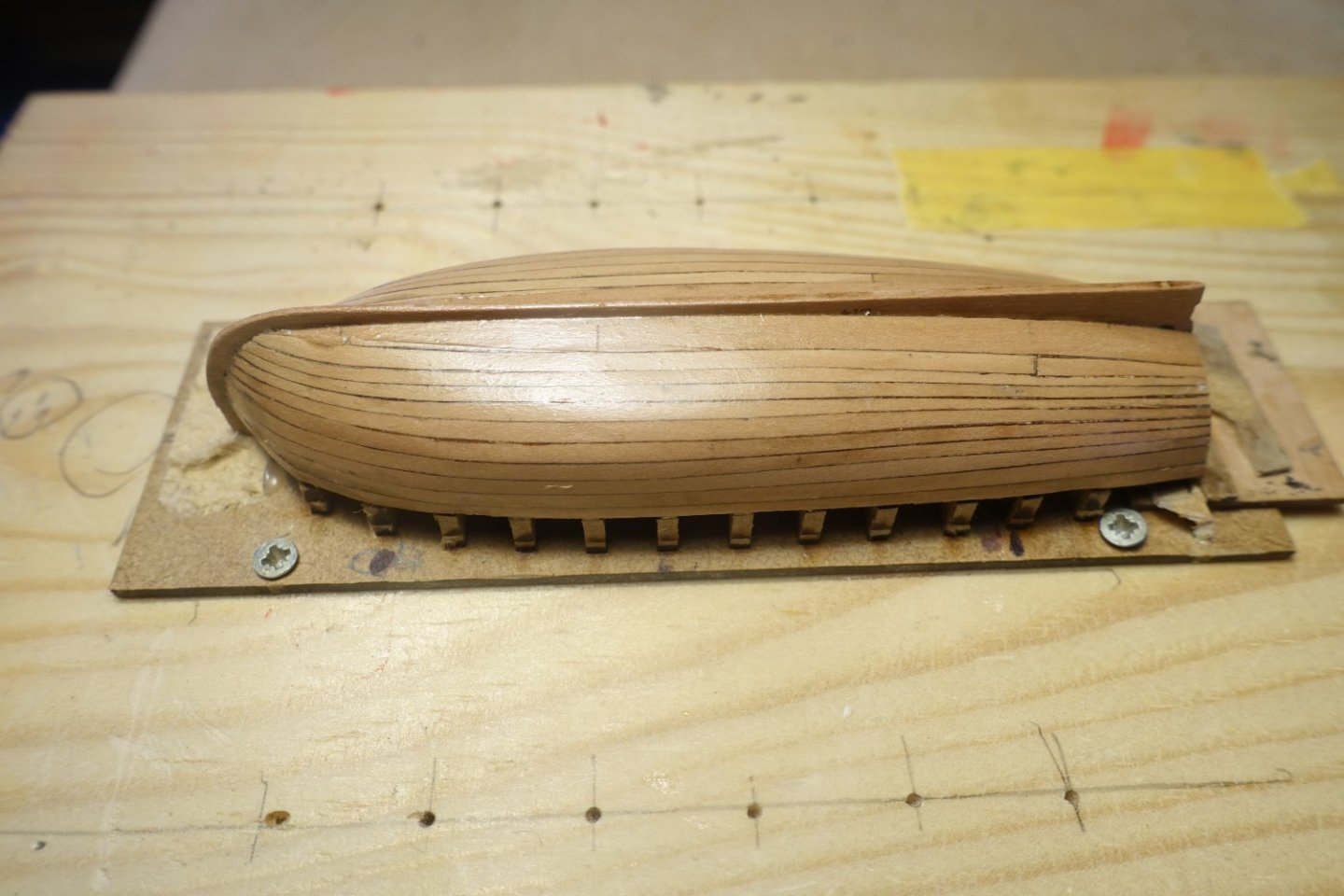
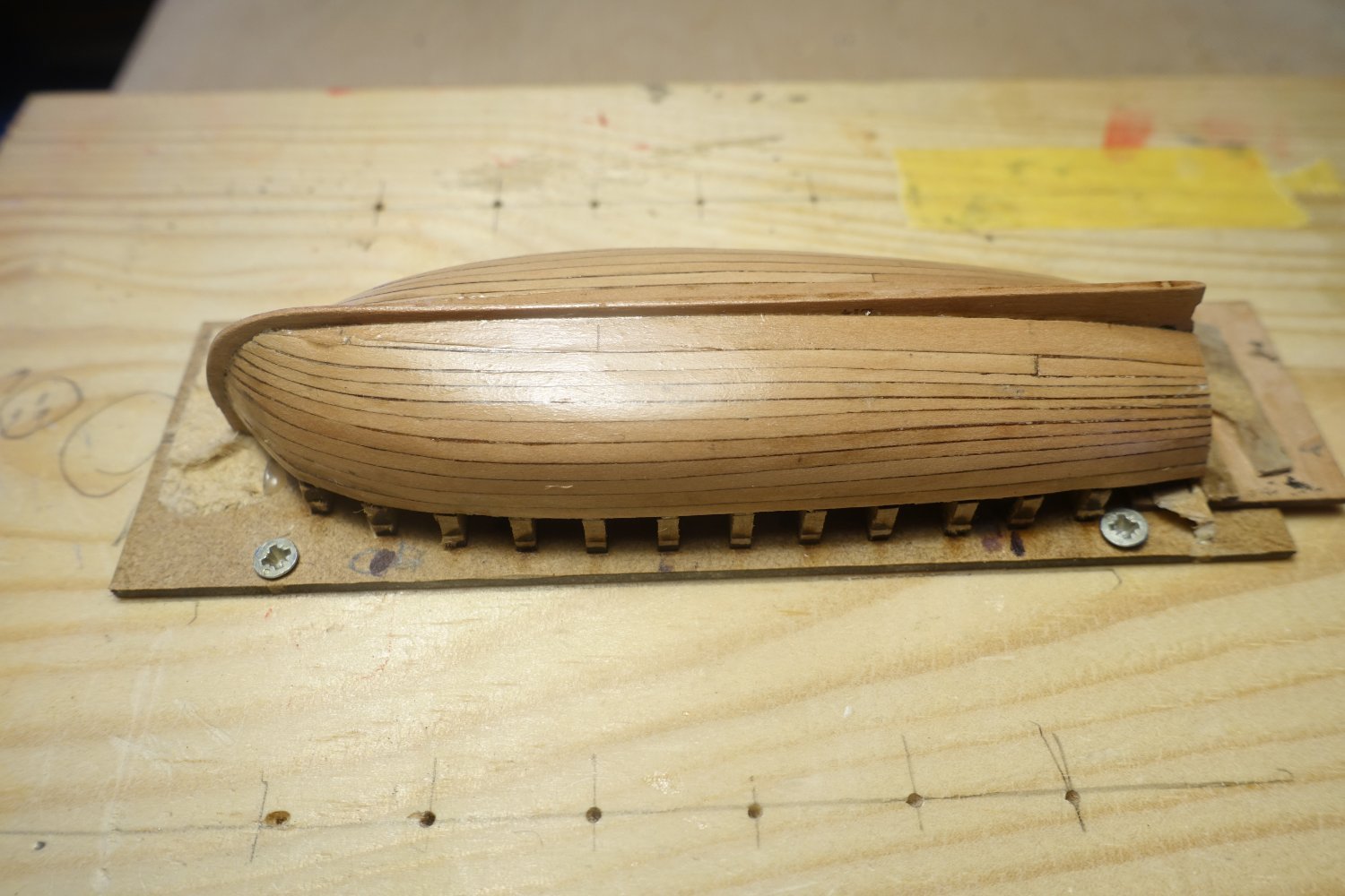
The hull was sanded. I started with 180 grit and finished with 320 grit.

I want to present the boat later without paint and also without a waterline, as I always find it nicer when the wood presents itself.
I therefore applied three coats of thinned clear varnish. Unfortunately, I missed a pencil mark on the garboard. But I won't sand it all down again, as the line will come to the bottom later and therefore won't be visible.
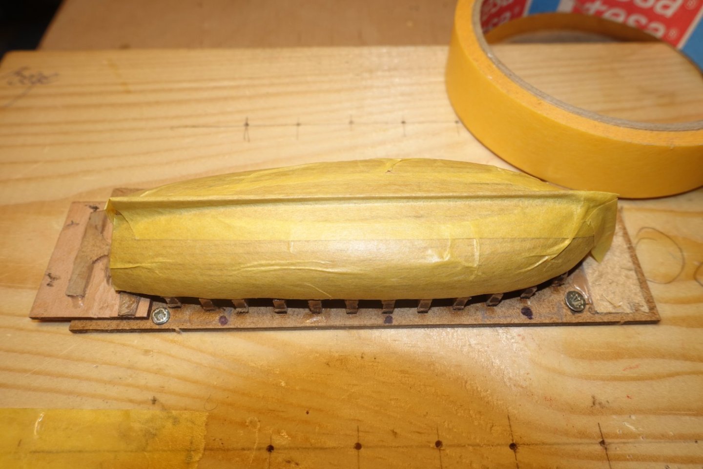
I covered the boat (including stem) with masking tape to prevent bending after removing the frames and to protect the wood.
This is the current status of the launch. Furhter posts will follow as soon as a corresponding construction phase is completed.
-
Garboard strake.
As in a ship, the strake should also have about twice the thickness of the regular planks. To make this I used the edge of the 0.6mm thick wooden sheet from the Sphinx kit and cut it off.
 the
the
I then attached the cut-off area to a 4x4 mm beech strip with double-sided adhesive tape and sanded down the overhang of the 0.6 mm thick wooden strip to the 4 mm using the beech strip as a guide. There are certainly other ways to make the garboard strake.
The garboard strake was first cut and sanded by feel in the bow area.
Both garboard strakes were then fitted with CA. The frames are in the keel area and will later be covered by the floor so that the glue is no longer visible.
- CiscoH, bruce d, JacquesCousteau and 3 others
-
6
-
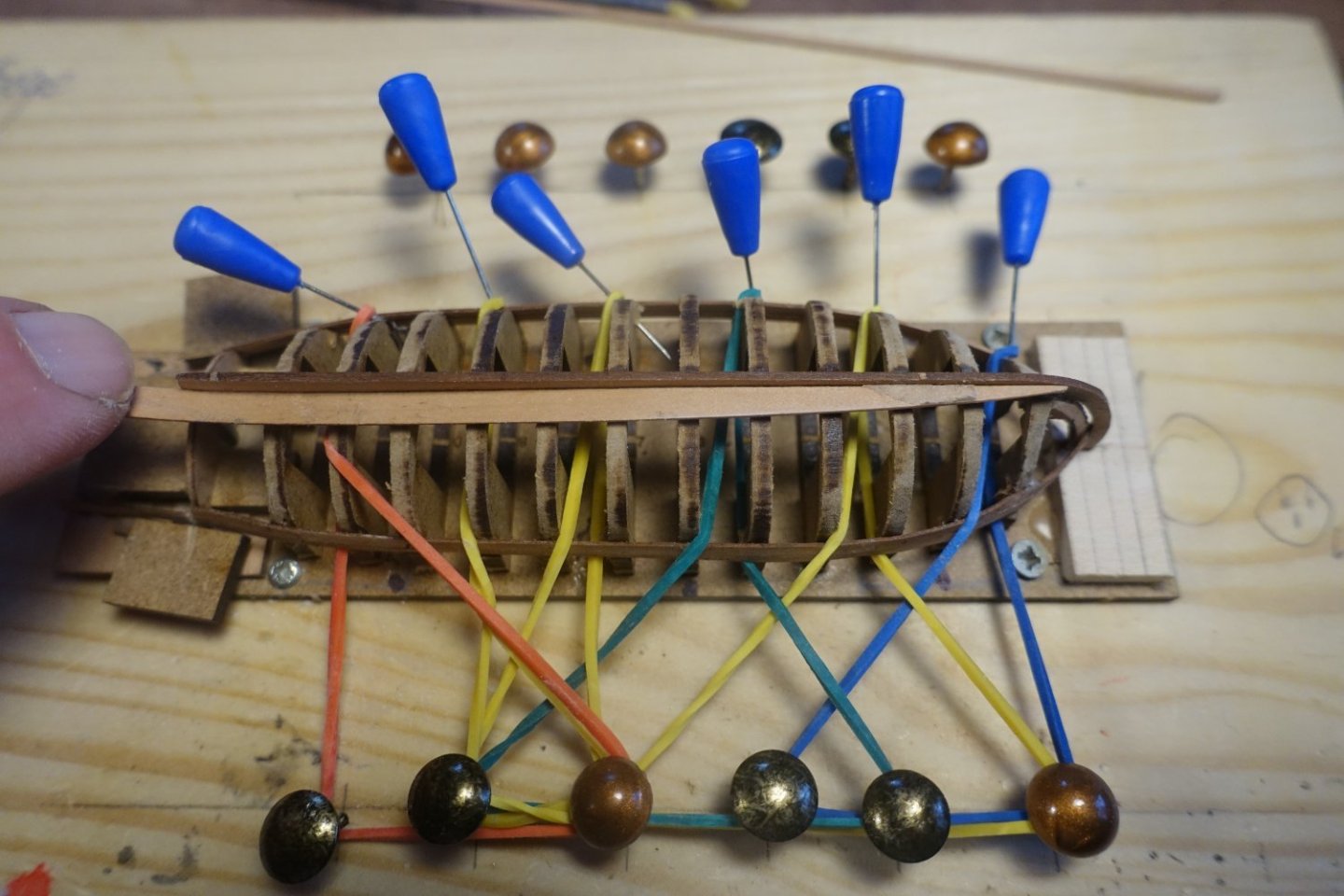
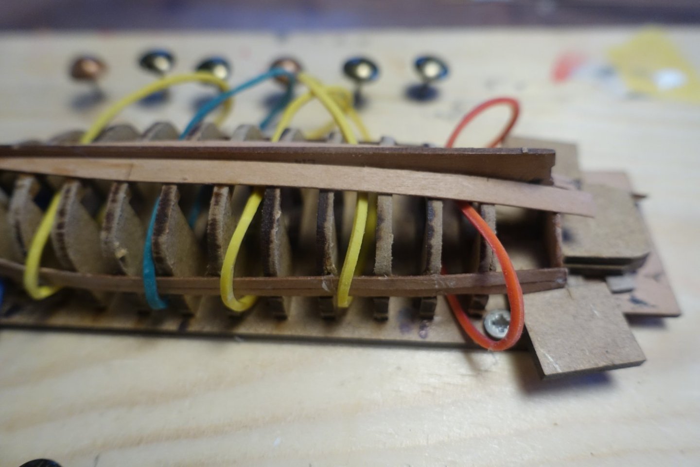
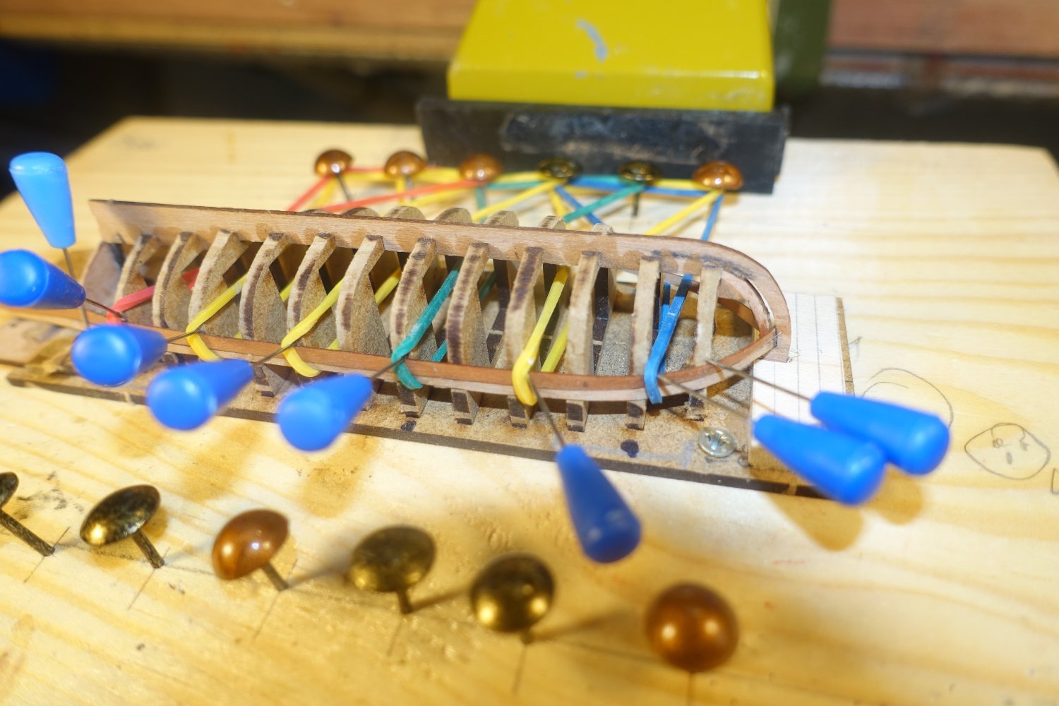
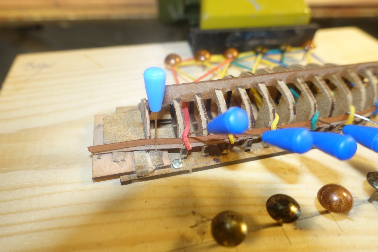
I tapered the bow area from the second strip onwards, trying to make the taper on the port side the same as on the starboard side. The frames are cut so precisely that the distances from the first strip to the keel are the same on both sides
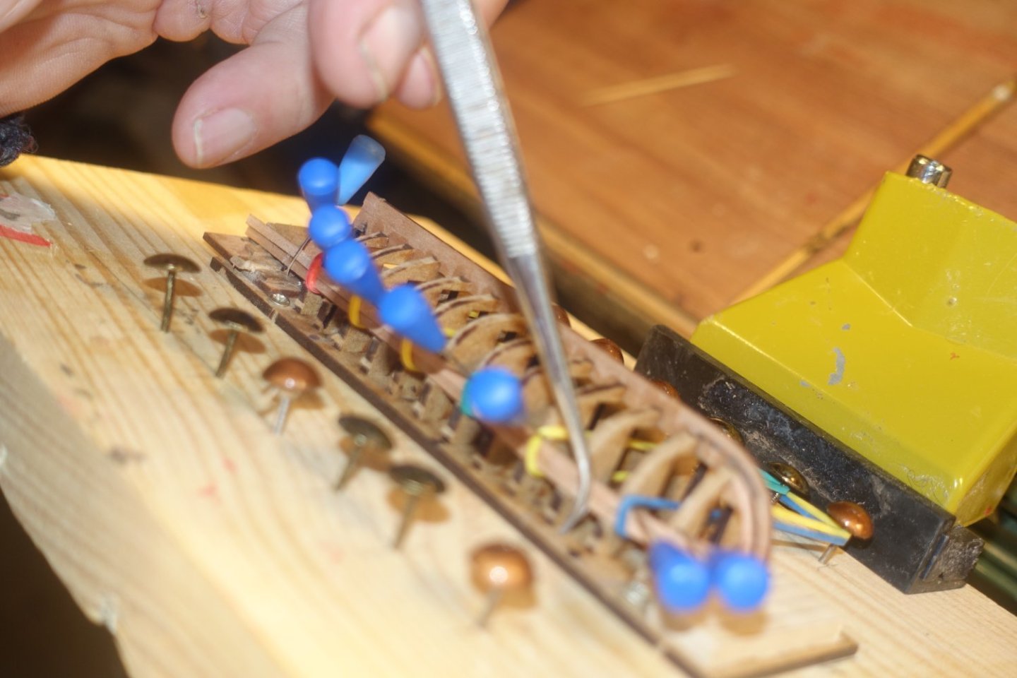
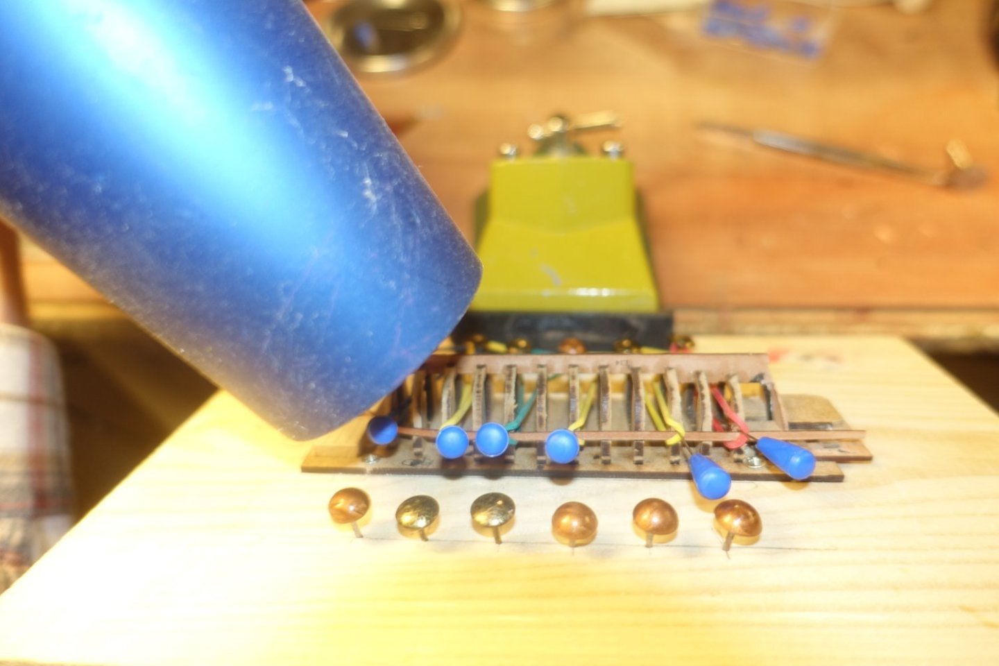
The planks were watered, laid out wet and pressed onto the frames and first strip with the help of the pins and rubber bands.
 .
.
The planks were watered, laid out wet and pressed onto the frames and first strip with the help of the pins and rubber bands.


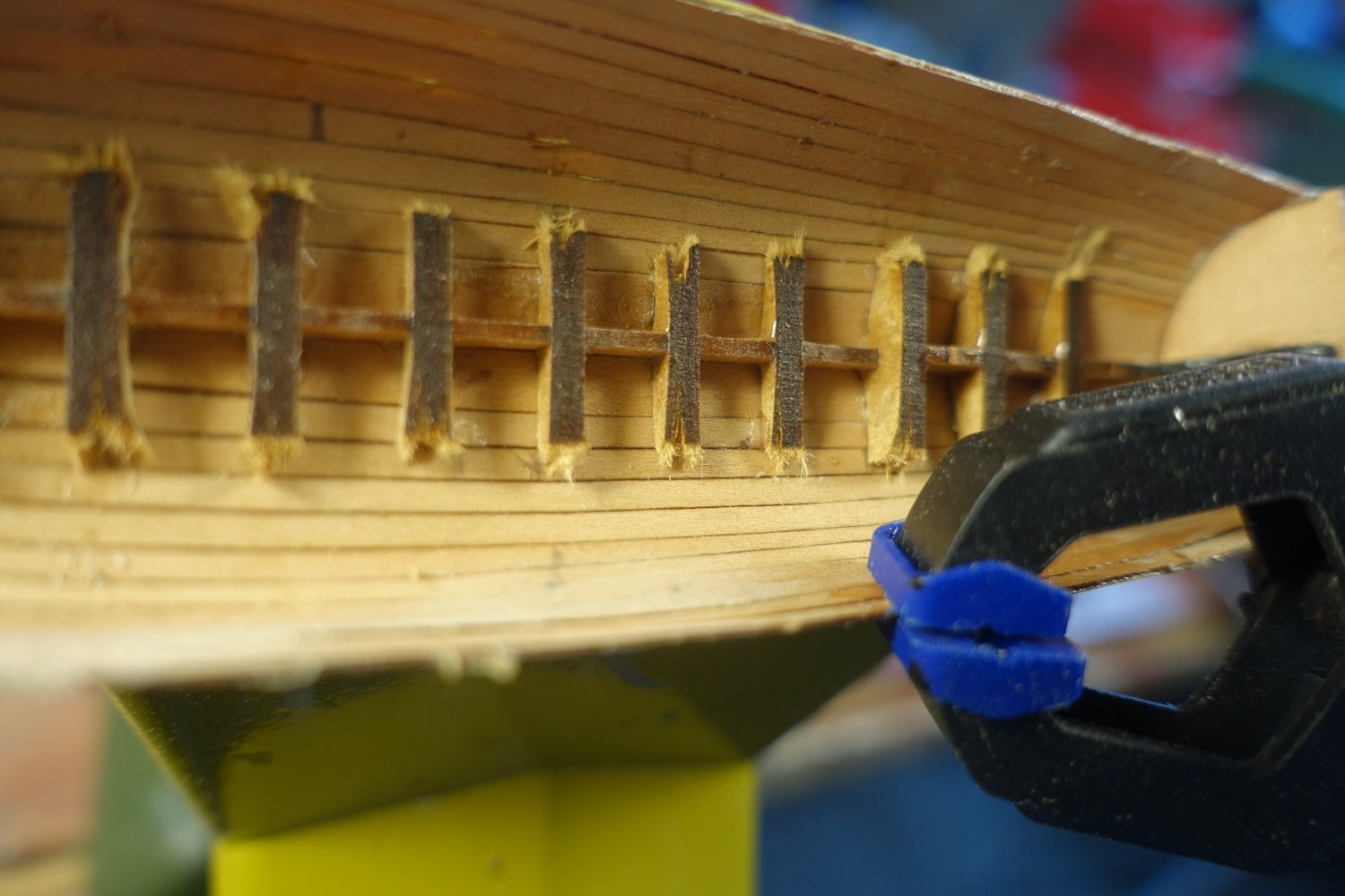
The planks were then dried again using a hair dryer (approx. 5 min). Without removing the strip, PVA glue was applied to the area between the strips.
Where the strip protruded, it was pressed against the first strip. A small amount of PVA-glue between the planks also holds the strips together (photo out of focus, sorry). The protrusions are usually very small. However, the planks are also extremely thin, which leaves little room for sanding later.
-
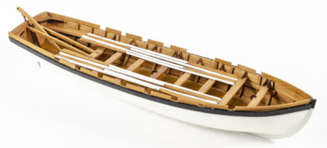
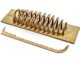
Photo taken from the building instructions of Chris/James
Chris Watton (Vanguard) has some smaller boats in his range which he offers separately and which are also part of some larger kits (Indefatigable, Sphinx). I am currently in the process of building the Sphinx and have noticed that opinions about the boats are divided here in the forum ("torture" versus "fantastic"). I would therefore like to describe the construction of the Launch in more detail. You can also find a clear description in the reports from Blue Ensign. I have of course based my description on these reports. However, I have come up with a few more tricks that - at least from my point of view - make it easier to build these small boats. Perhaps Blue Ensign's and the other reports and/or mine will encourage a few more people to build these beautiful boats. I don't want to discuss whether the model is historically accurate or not. I just want to encourage some to take a look at these boats and share my experience on how to handle these delicate little boats.
I don't have any photos of the very beginning, but this can easily be seen from Chris'/James instructions.
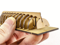
Photos taken from the building instruction of Chris/James
It seems important to me that both the bow and stern transom are well fixed. These are the most sensitive areas. I secured the transom both inboard and outboard.


I glued the frames to some points in the base plate with CA glue and marked the points so that I could cut the frames out of the base plate later if necessary. There is enough space on the top of the bulkheads to be able to use a knife or a small saw. I used CA instead of PVA to fix the frames because I want to bend the planks later with a hairdryer and the heat would soften PVA glue.

For further sanding, I used sanding sticks (100 grit) and tried to sand three frames at a time (similar to a large ship). The charring from the laser cut is a good guide. As long as there is still a lot of it visible, sanding is usually not enough
A first test with a plank shows that the first two frames have not yet been sanded sufficiently (also visible in the remaining charring).
After re-sanding, the plank fits better, but the frame still needs to be sanded a little.

When adjusting, I also beveled the transom so that the planks fit well here too (photo unfortunately a little out of focus).
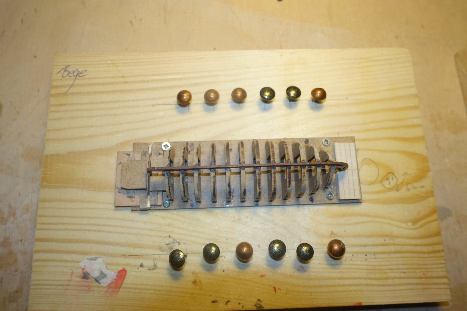
The assembly was then screwed onto a wooden board and 6 nails were driven into the starboard side and 6 nails into the port side at a distance of approx. 4 cm from the hull.

The first plank is not tapered. However, the bow end has been slightly chamfered so that it is flush with the guide slot in the stem. The planks have also been marked to show how far they can be inserted into the slot without obstructing the other side.

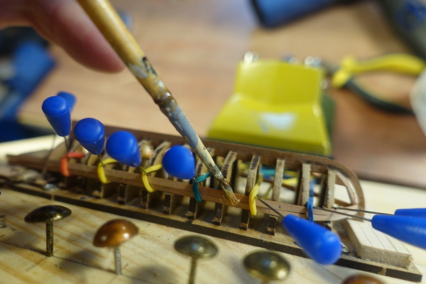
The planks were soaked in water for about 15 minutes and then fixed to the frames. The pins were guided against the keel side of the plank with very light pressure. Rubber bands were passed around the pins and tension was applied via the nails on the opposite side. The guiding around the pins ensures that the planks are pressed against the frames but do not bend.

The fixed planks were heated with a hair dryer for approx. 5 minutes. This time is usually sufficient for the planks to retain their shape and size.
In the stern area, the plank is pressed against the transom with tweezers during heating.

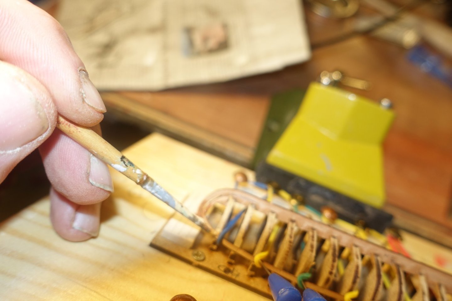
I did not remove the plank again, but applied PVA directly to the frames or the stem and finished with a slightly damp brush. PVA is only applied to the frames for the first plank, then later between the planks. I only used CA on the transom to fix the planks in place.
-
2 hours ago, chris watton said:
Cheers guys
Of course, I cannot please everyone all the time, and will always have someone not happy. Here is a snippet of an email I received earlier this week:
"I have now decided on the Sphinx kit and the kit was delivered today from a German dealer. I have to be honest but very surprised that the cannons are included in the kit in plastic. For a kit that costs 1000, - €, this is really not acceptable. Is this how the kit is delivered by you? Also, the anchors in plastic do not correspond to the otherwise flawless level of the kit."Well, I did initially offer metal cannon and anchors for Alert. The problem was that the cannon were actually oval in shape, and the monogram just a blob, and the anchor was rectangular in profile, rather than square, plus the hole for the ring was no longer a hole, and both had mismatch. Also, the octagonal winch for the Alert shrunk so much, it no longer fitted, plus that too was 'squashed'. I threw the whole lot away and initially went for cast resin, followed by 3-d printed resin. I guess the customer thinks that 'plastic' is a cheap and quick way to rip off the customer, rather than a new technology to more accurately represent the original parts, with zero shrinkage, no mismatch, and every hole perfect. The 9-Pounder cannon for Sphinx takes 3.5 hours to 3-d print 5 kits worth. In that same time, 100 kits worth can be produced if cast. Same applies to the stern decoration, which takes 7 hours to 3-d print, and you keep all the definition that is on the master file, rather than a blob of metal that wouldn't even pass muster for a children’s Clair's Accessories shop.
On a personal note, I really have never cared too much about the material used for parts, as long as the end result looks right.
I did originally sub contract the cast and 3-d printed resin parts, which was far from cheap. For example, a single 32 pounder cannon barrel cost 1 Euro. I think some do not differentiate between high volume injection moulded plastic and much lower volume cast or 3-d printed resin.
I'm also busy with the Sphinx at the moment, or rather it's keeping me busy. The cannons are of excellent quality and can be perfectly restored to their 18th century condition with enamel paints and a little powder.
- thibaultron, chris watton, Canute and 6 others
-
8
-
 1
1
-
8 hours ago, GrandpaPhil said:
Very nicely done!
Thanks, it was something for in between
- thibaultron, GrandpaPhil and mtaylor
-
3
-
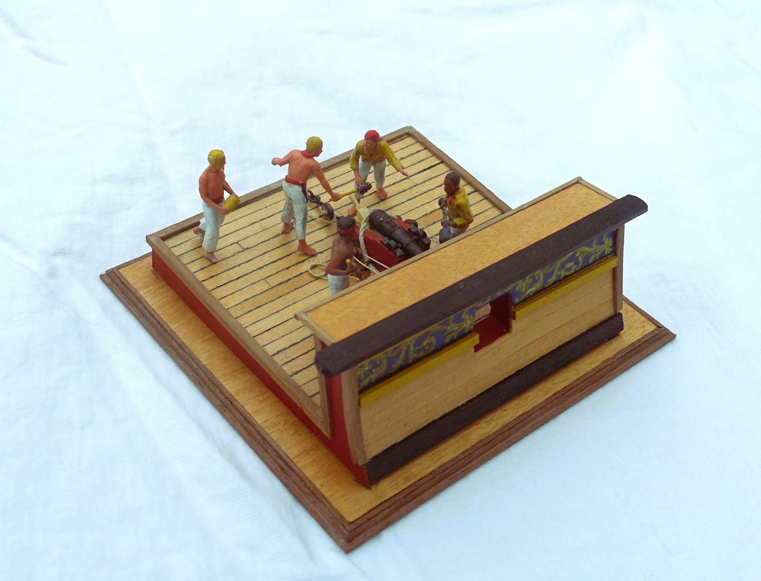
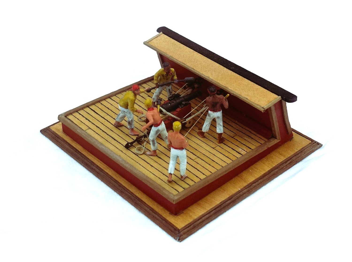
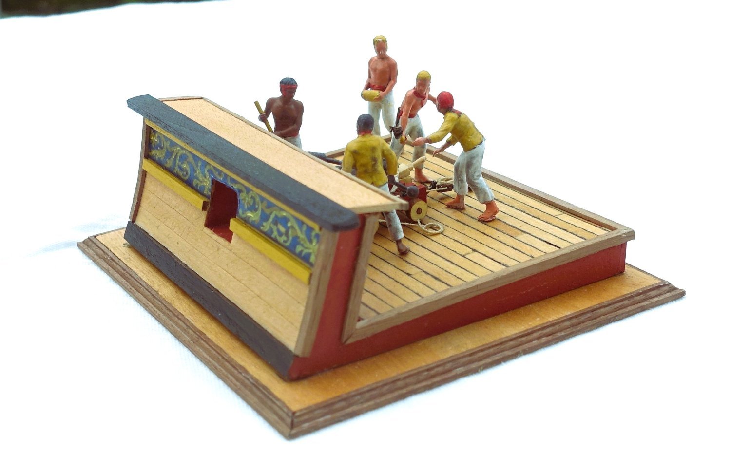
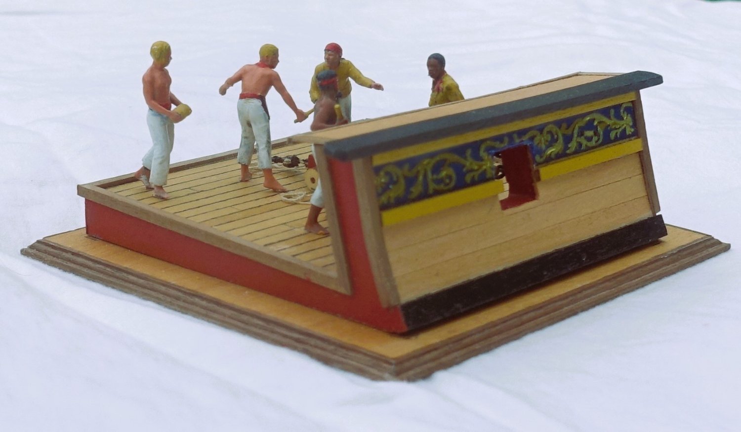
Actually I wanted to decorate the Sphinx with the wonderful figures of Chris (Vanguard models). However, I found it a pity that the crew is covered by the dinghies. So I made a cut of the ship's side with gun during the loading process. For the colouring of the crew I followed Ron's example:
-
Great to have you back in the yard. I hope you didn't get the virus too bad. It was certainly an excellent idea to order the blocks from Chuck. As far as I remember, Chuck has a description somewhere of how the blocks can be rounded in a special device. As far as coiling the ropes is concerned, I had first tried to make an eight loop like Delacroix, but there was not enough room.
Have fun,
Clark -
-
15 hours ago, GrandpaPhil said:
Congratulations! Well done!
Thanks!
-
On 12/20/2021 at 9:19 PM, safemaster said:
Well done Clark 👍. How wide is that case with the oars displayed?, looks pretty deep. I wonder how the oars would be stored when not in use?
Michael D.
Thank you very much. The width of the model including oars is 49 cm, I designed the display case for an internal width of 50.5 cm, I did not want to "consume" too much space, because I also discussed with the admiral longer where to put the display case. As for the placement of the oars, I interpreted the descriptions and the pictures that they were not hidden even with the ship under sail.
Thanks for stopping by.
Clark


24 ft Launch by Clark - FINISHED - Vanguard Models - 1:64 scale
in - Kit build logs for subjects built from 1751 - 1800
Posted
The boat is ready and waiting to be lashed to the Sphinx.
I hope that this report will encourage some people to build these nice little boats. After all, they take up very little space,