


Clark
-
Posts
238 -
Joined
-
Last visited
Content Type
Profiles
Forums
Gallery
Events
Posts posted by Clark
-
-
-
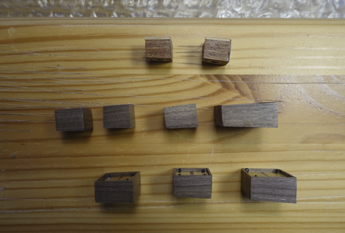
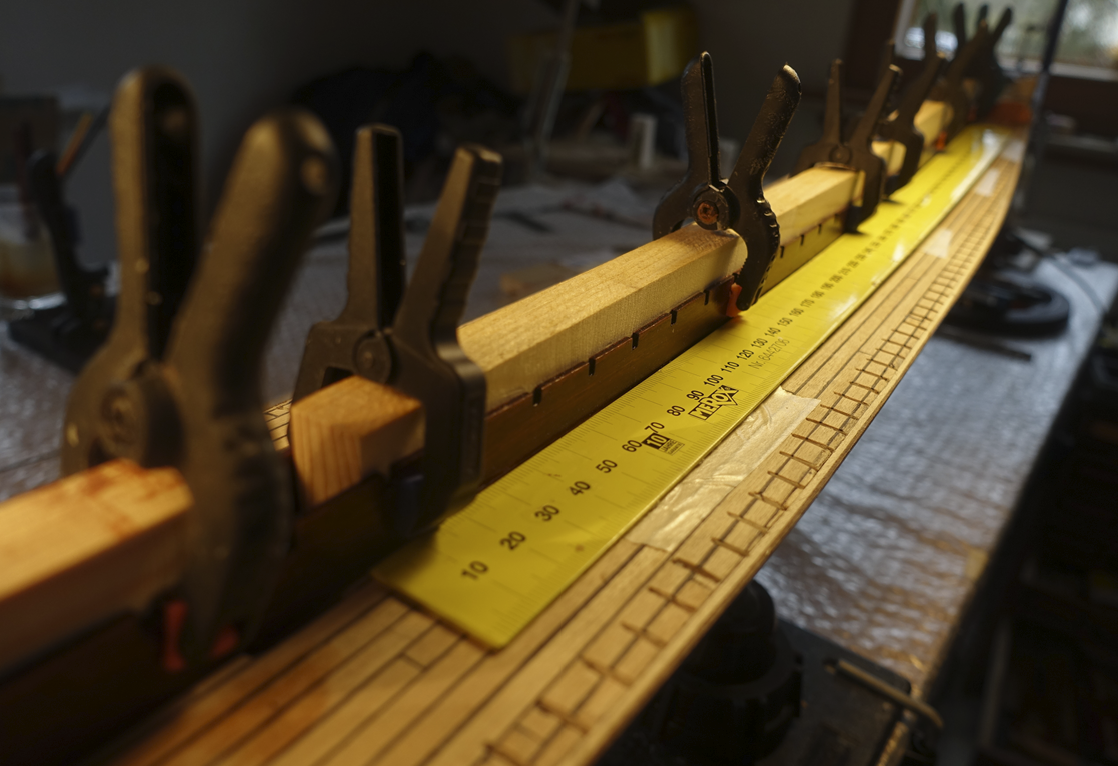
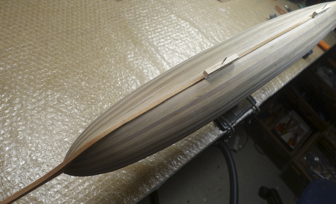
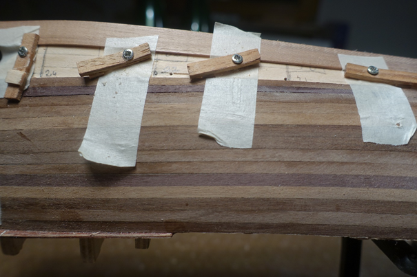
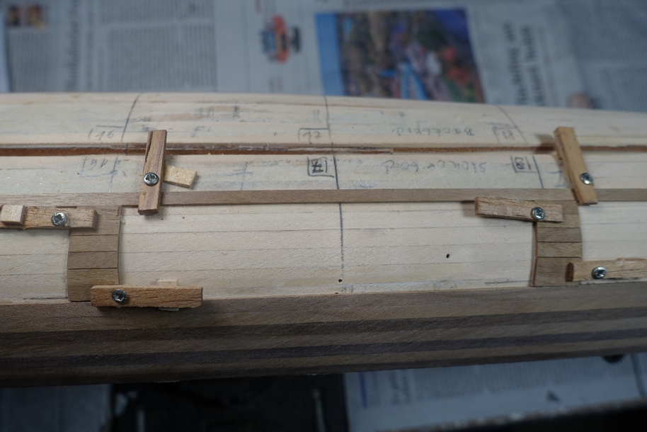
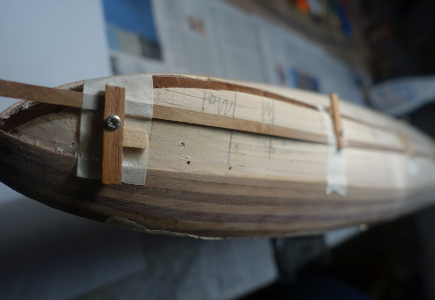
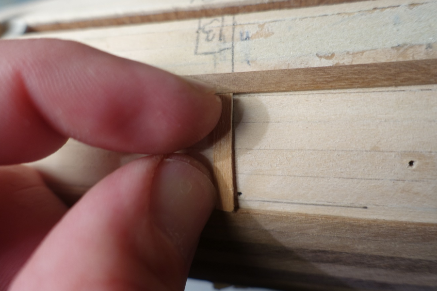
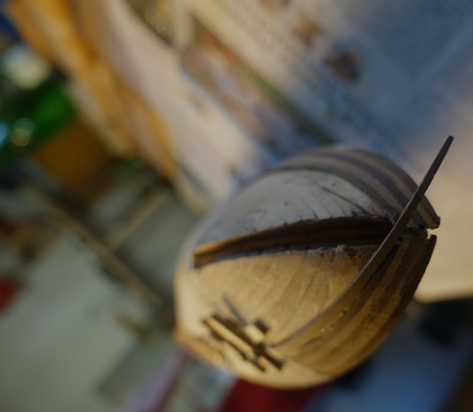
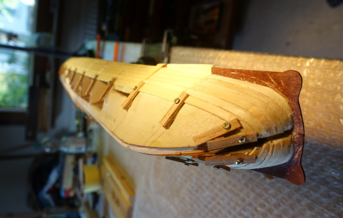
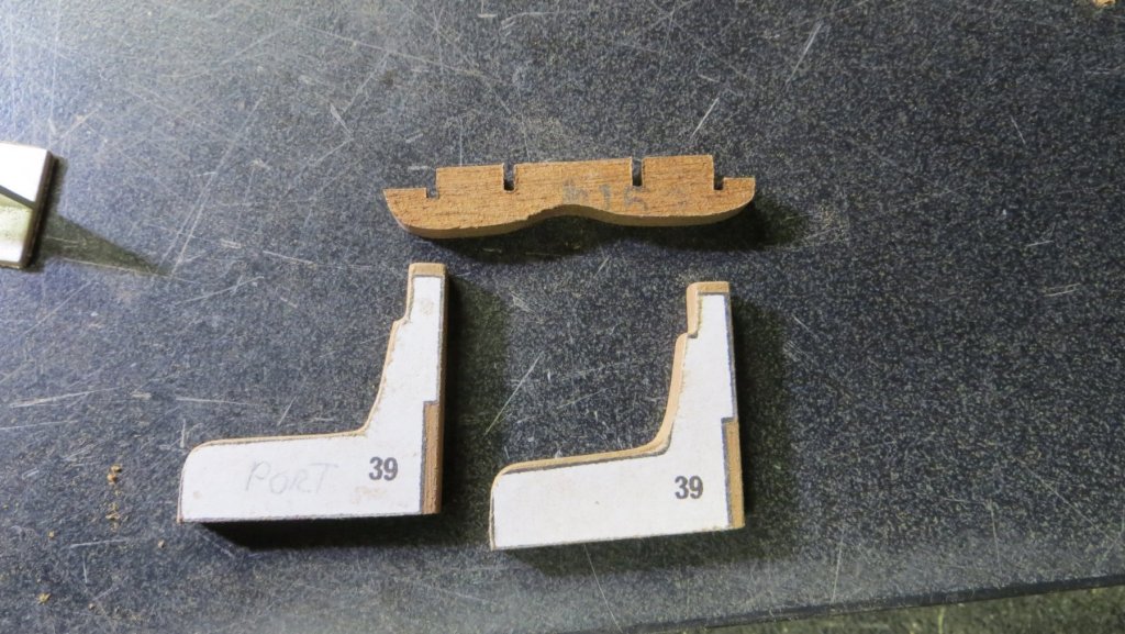
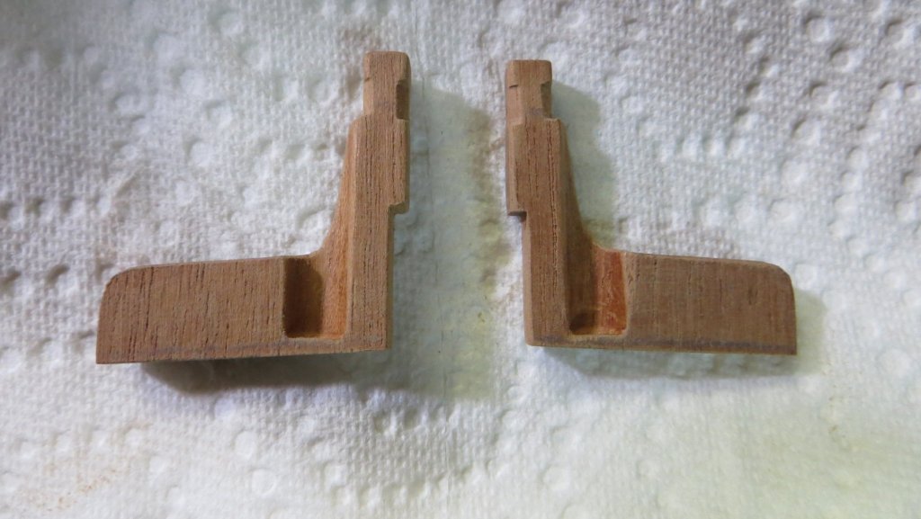
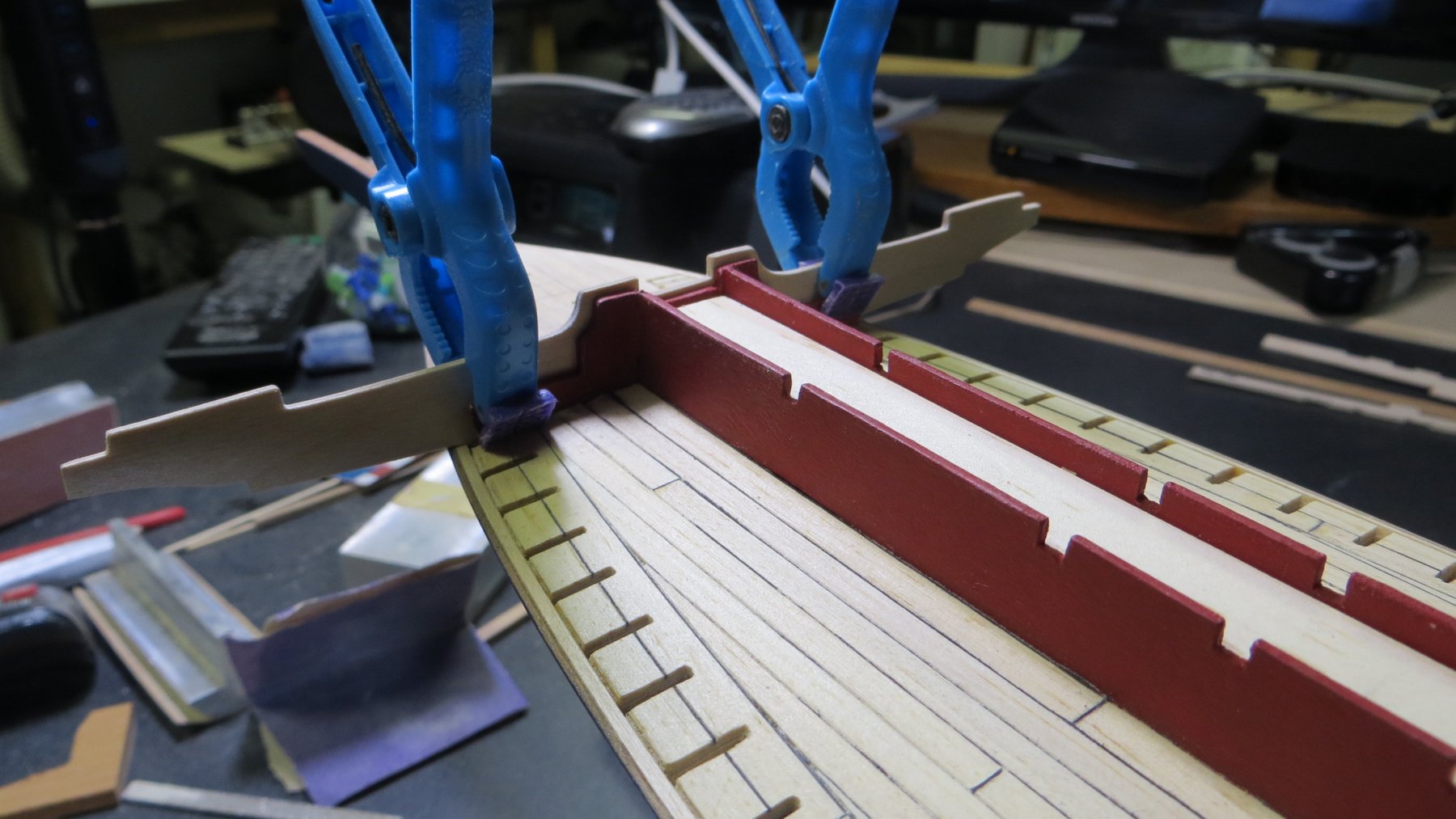
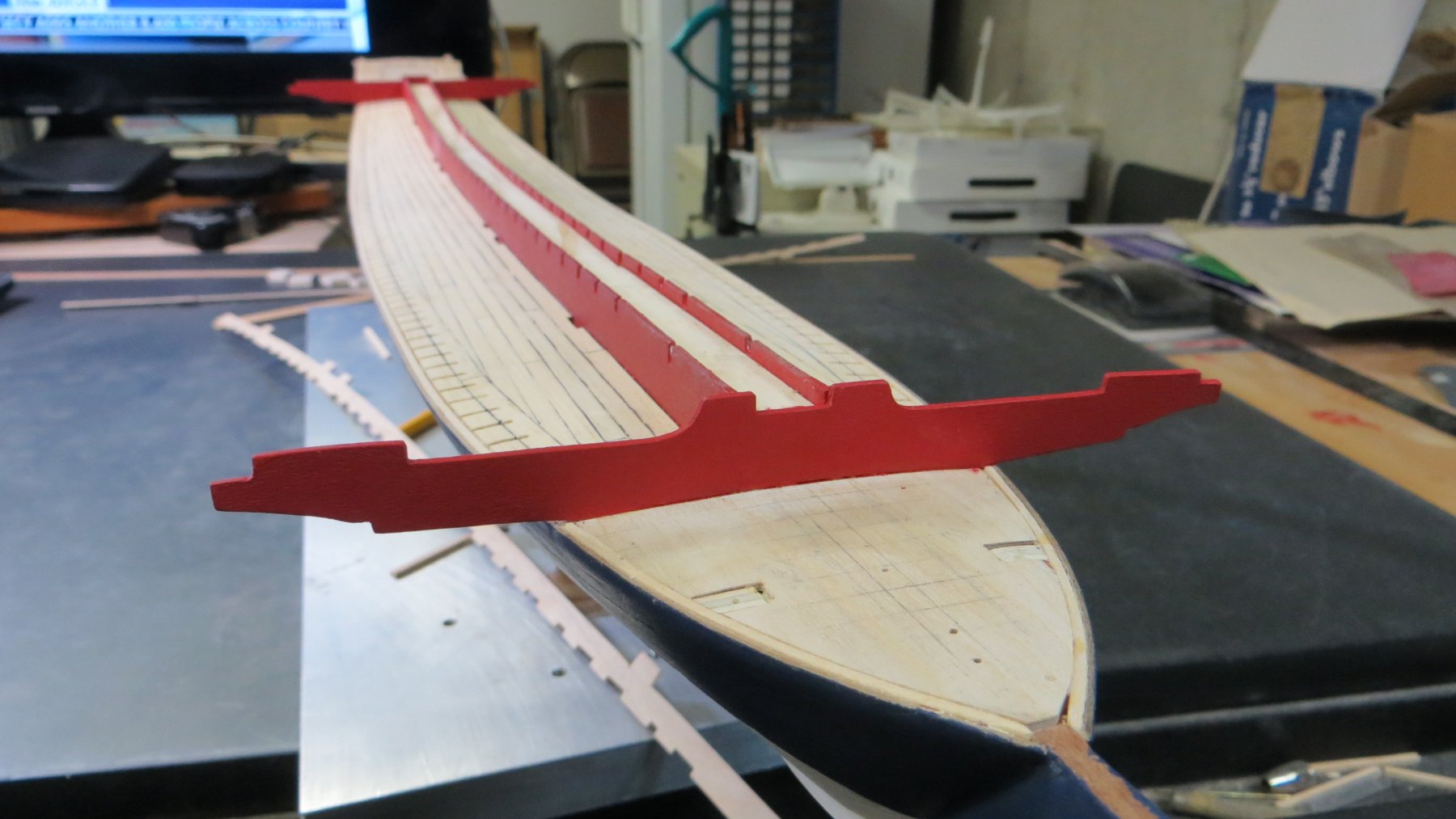
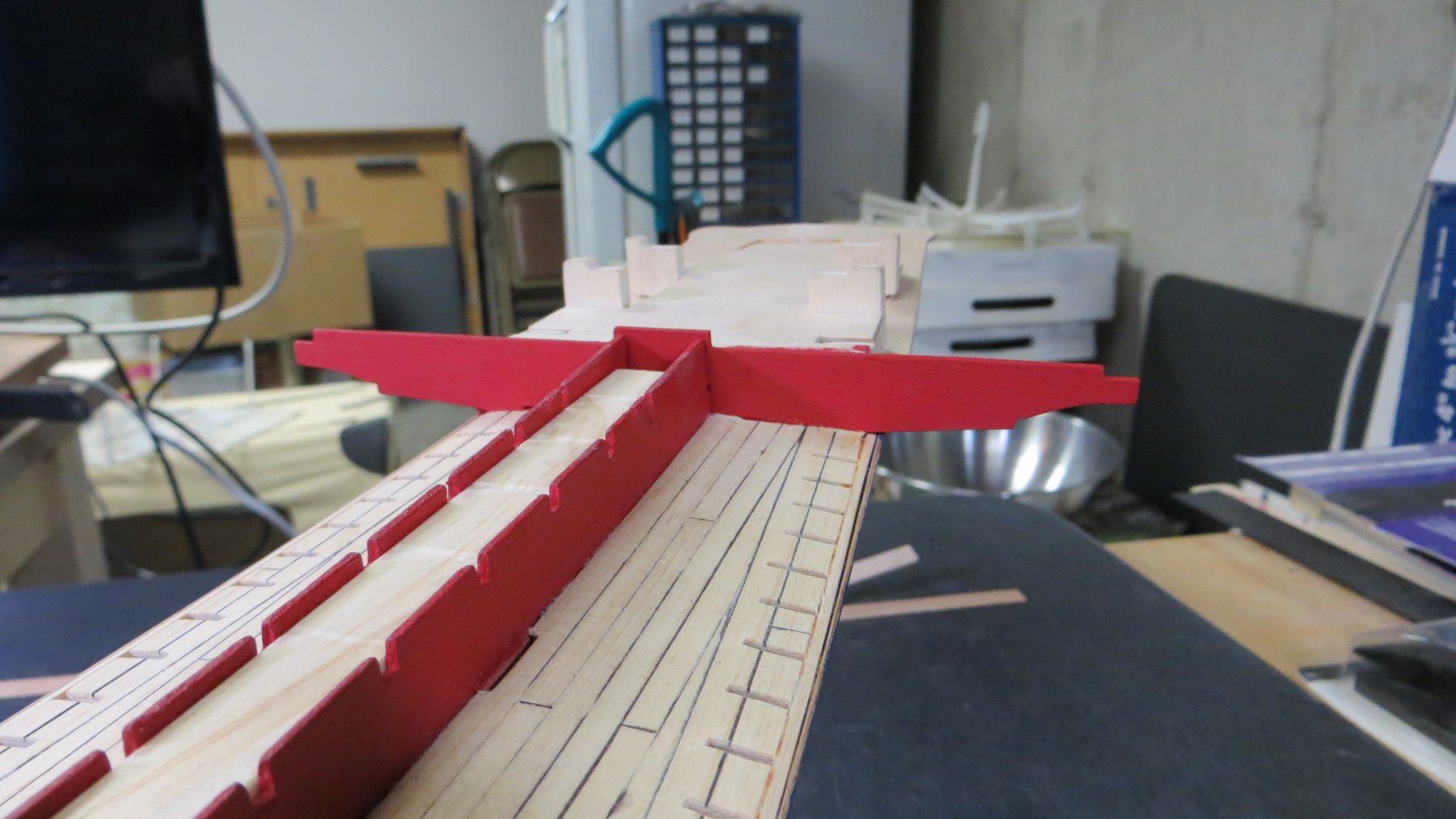
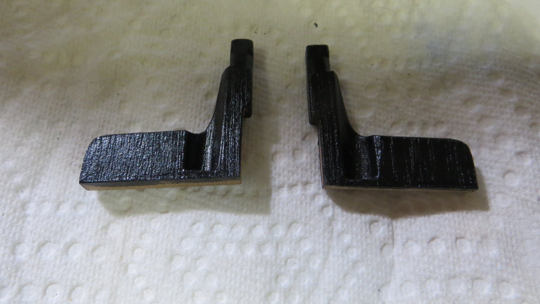
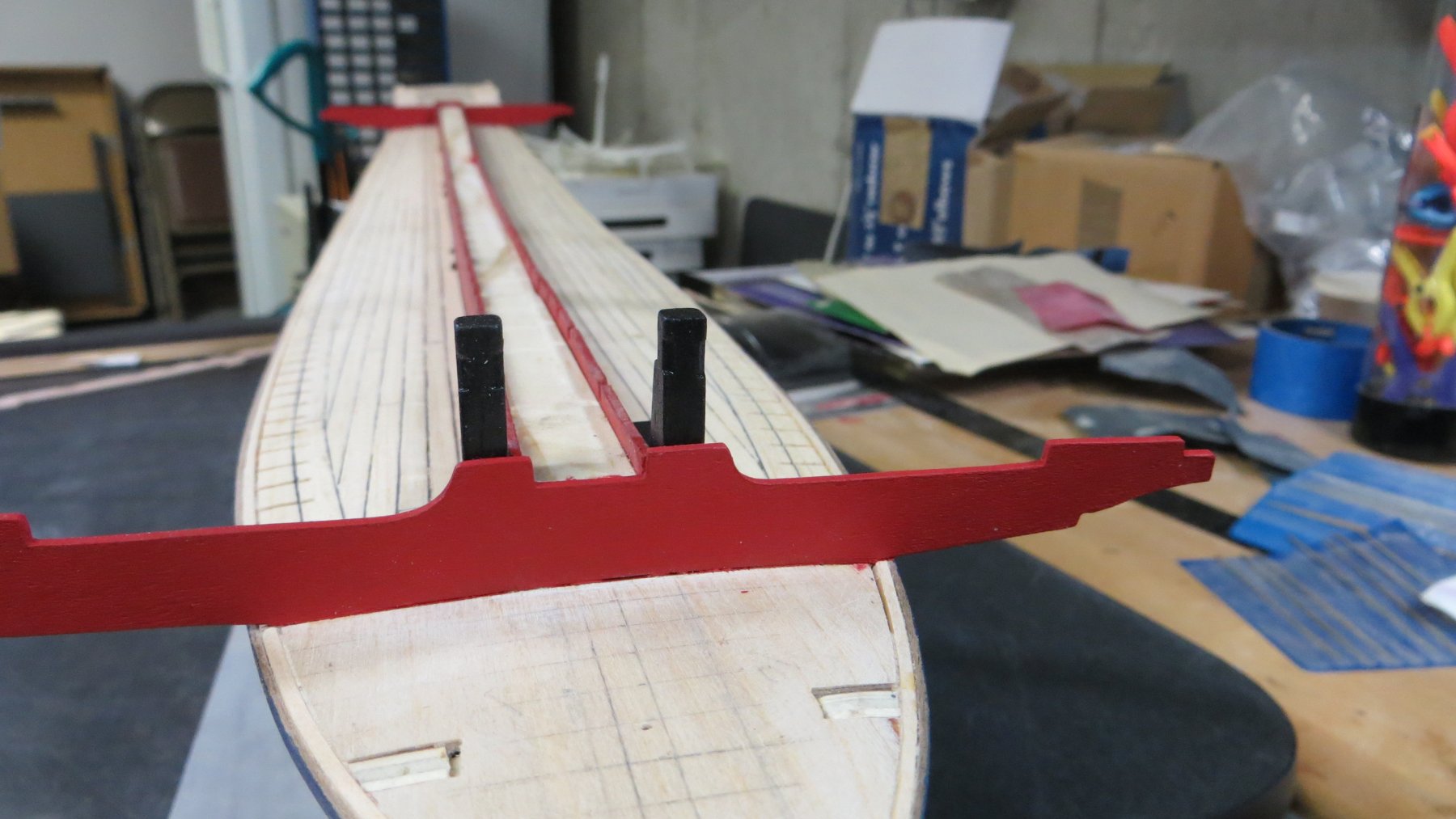
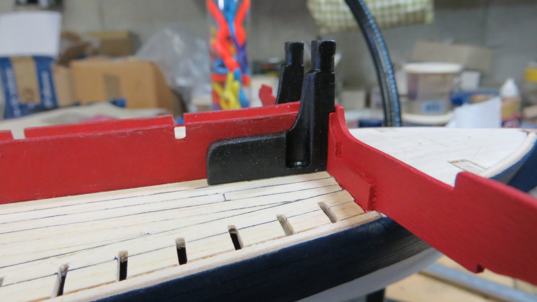
When building the hatch coamings, I put the lids at a higher position than recommended in the Corel plans. Regarding the coamings for the anchor line, it should probably only protect the hole in the deck from water flooding in. Nevertheless, the rope would be damaged if pulled along the edges. Thus I added a protection. The hatch coamings had to be tapered due to the sloping deck line in the line from the middle to the hull. It is necessary to keep the upper line of the hatch coamings horizontal since the footplates of the oarsmen will be attached later.
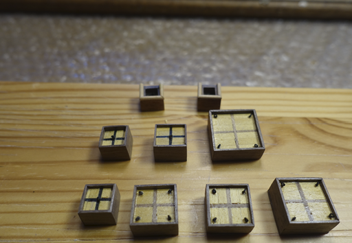
To put the coamings in place, ship had to fixed. Hull was protected with painter tape. Ship was put in the slipway, levelled again and fixed by balsa/foam supports. Since I was afraid that the long stem post might get broken (it is really a long and small hull), it was covered by balsa pieces.
- fmodajr and GrandpaPhil
-
 2
2
-
On 5/1/2020 at 1:30 PM, fmodajr said:
Hi Clark,
You are making some nice progress.
Model looks terrific so far!
Frank
Thanks a lot, Frank. Did you have the chance to get back to the bench? I am eager to read news of your progress. Your report is more than inspiring.
Clark
-
I decided to reseal the hull. I sanded it (grade 120, 180, 320) which took me about one week. It is really not the job I like.
After sanding, I sealed it with the water based diluted (~20% H2O) acrylic varnish.
Corel material of the supports for the middle gangway and thwarts is made of plywood. The best way may be to replace them by normal wood. I relied on the ones provided by Corel. I stained them mahogany to cover the plywood character a bit.
Next step is building the hatch coamings.
- GrandpaPhil, J11 and fmodajr
-
3
-
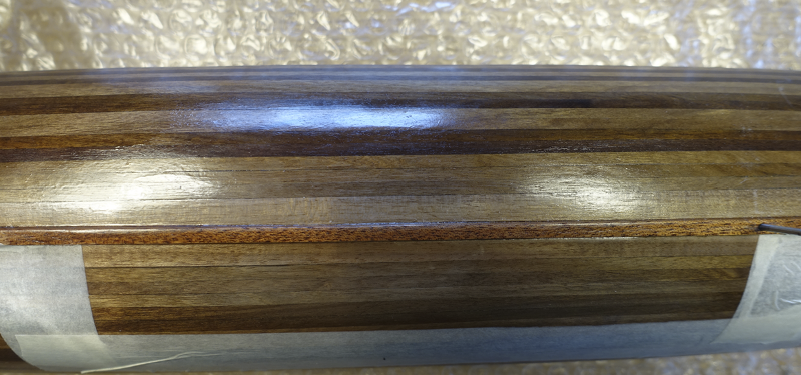
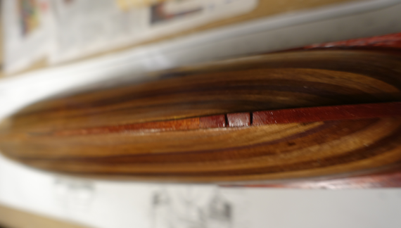
Meanwhile I have tested other varnishes and oils on walnut pieces. Finally, I found one on acrylic basis and tried it on part of the hull sanded. In the photo below, the glossy varnish (Nelson) can be seen on one side and on the other side the acrylic one (water diluted/surrounded by painter tape) on the other side . I will put the ship aside and have another glance on it.
-
19 hours ago, GrandpaPhil said:
The blue and white with the gold fleur de lis was difficult to paint when I built the Heller version. I am still going to try it when I build my replacement for it in a couple of years.
When starting the Reale, I shortly hesitated to paint it to get nearer to the orignal one. It is probably a never ending discussion if wood ships should be painted or not. I am a fan of the wood structure, thus I will probalby stain only the plywood pieces.
- Gimo and GrandpaPhil
-
2
-
2 hours ago, GrandpaPhil said:
Are you planning on painting the hull?
I like the wood structure to be visible. Thus I only want to seal the wood with varnish.
Im will probably sand the old varnish down.
Clark
-
-
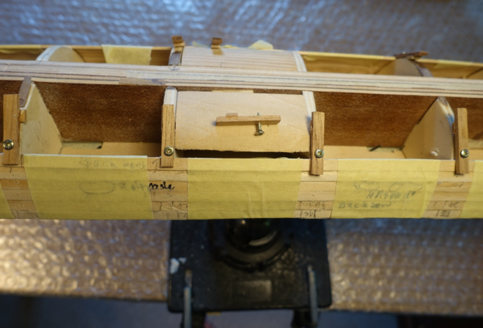
Not much progress in the meantime. But the kit and plans urges one to think not only about the next two steps.
Shortened nails were put into the keel for the (much) later fixation of the ship in the final supports.
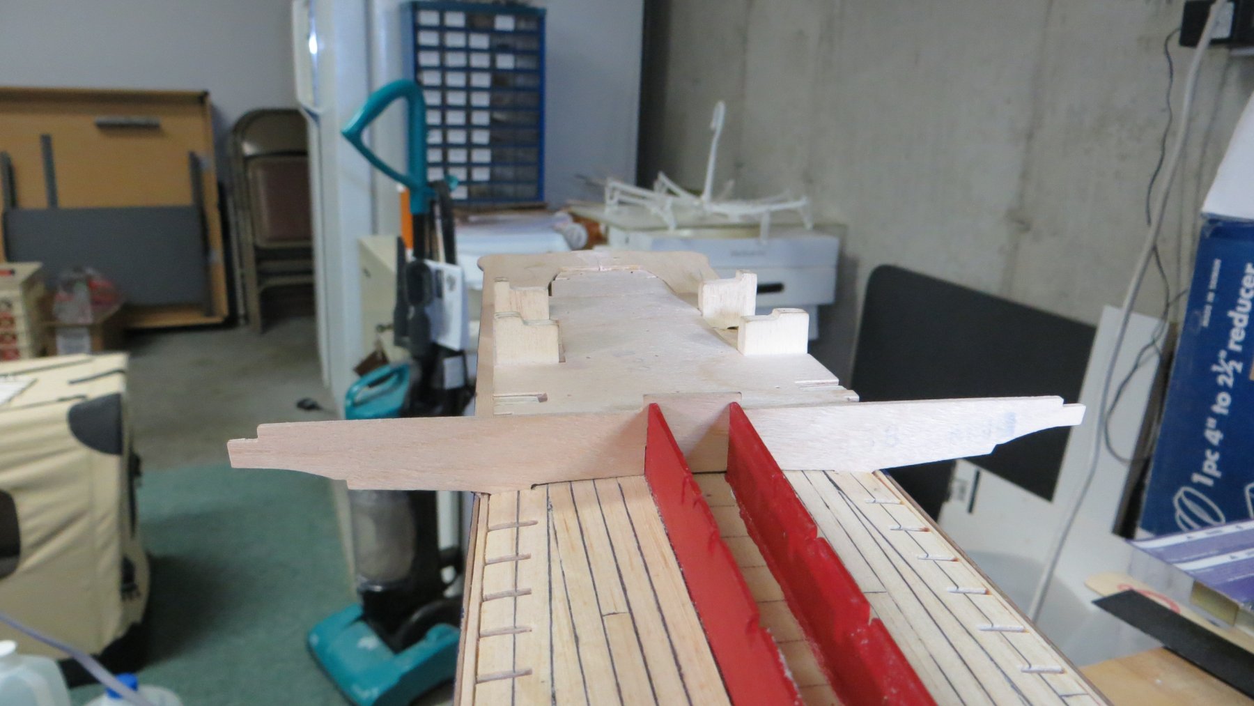
Final supports were already dry fitted since this will probably much more difficult with all the stuff on the deck. Final supports provided by Corel were covered with walnut strips on all sides to hide the plywood character. However, I am not sure if I will really use the Corel supports at the end.
Final supports were also adjusted with the ship on them. For levelling in the longitudinal axis, the difference in height between the two support points was extrapolated from the Corel plan. Same points measured on the ship when put on the supports had only a small greater difference (~0.5 mm) than in the plan. I did not correct it. Levelling in the vertical axis (starboard / portside) was a bit more tricky and done with the help of spirit levels and caliper.
Wood/foam supports were adapted for following mounting and fixation in the slipway.
- J11, GrandpaPhil and fmodajr
-
3
-
You mean the curve from stern to bow? It may be the best to test the bending proceeder on an extra plywood piece. Usually wood can be bended by applying heat. If the wood is watered, the water helps to spread the heat. I am not sure how plywood reacts.
Clark
-
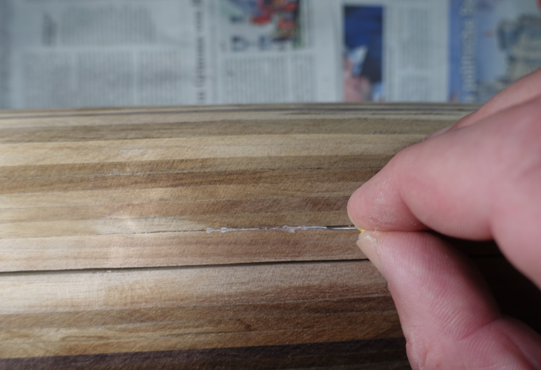
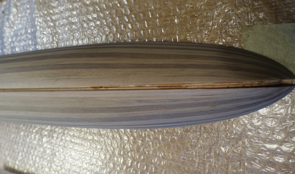
Second planking is now ready. Hull was roughly sanded. After first sanding I noticed a gap between the garboard strake and the regular planks. I probably forgot beveling of the garboard strake. Gap was filed with PVA and sanded over (the greater gap in the photo is the slot for the keel, was widened, see below).
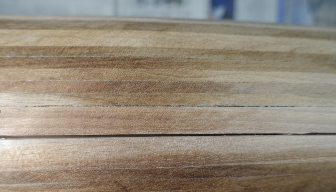
I proceeded in sanding and adapted the slots for the keel
- Zarkon, GrandpaPhil, J11 and 2 others
-
5
-
Corona gave me some time to be spent with the ship. I proceeded in planking and reading some more literature about galleys.
Regarding the ship, before attaching the last strips, size, bending and position of a “garboard” strip was tested. (I do not know if a garboard was ever used in this type of ships). Finally I decided to use a walnut strip 10 min wide as “garboard”. This because the keel is deflecting ~5mm from the middle to the bow and also to the stern which means that about 5 mm of width get lost when keeping the garboard in a straight line. After slightly attaching the garboard strip with the screw clamps, the remaining gap between the last regular strip and the garboard strip was measured according to the method described above. Garbord strip was then completely watered for about 30 min and again fixed in place to get the bending at the stern and the bow. It dried overnight and kept the bending.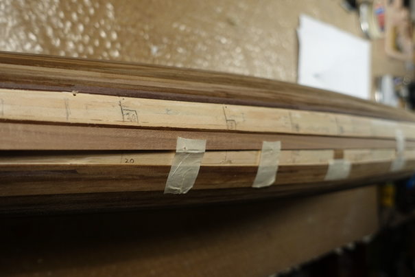
-
18 hours ago, fmodajr said:
Hello Clark,
I am away on a trip this week. When I return, I will send you some photos of the Shroud assembly plan from the Corel plan.
Basically, however, here is how Corel shows it being done.
Just above the waterline of the ship and below (underneath) the slots are 8 chain plates that are nailed to the side of the ship. (Eight on each side).
Attached to the tops of the chain plates will be chain links (supplied in the kit). These links go from the top of the chain plates, thru the slots. At the top end of the chain links, above the slots, you attach what Corel calls toggles. These toggles are what the shrouds will be fastened to. It is quite simple really, but a picture is worth a thousand words as they say and I will post some as soon as I make it back home early next week.
I hope this helps and makes sense.
Thank you everyone for the "likes" and for visiting. It is appreciated!
Frank
Hello Frank, thanks a lot. Meanwhile I browsed through the plans and found the picture showing the chain plates. I thought that the shrouds are fixed on the panks of the gangway. Thus you are completely right to enforce the planks. I am glad that you are going ahead to help me to avoid mistakes.
Clark
-
Frank, it looks perfect. I m still thinking about the holes you made for the shrouds. How were the shrouds fixed? Below the outer gangway is nothing. There are still some ropes in middle visible. Are these the ones for pulling the carriage of the main cannon. If yes, do you have any idea, where they were put on?
Still admiring your work.
Clark
-
On 2/12/2020 at 2:25 PM, fmodajr said:
Well done Clark!
I think all the effort you are putting in to the planking will be well worth it!
Frank
Thanks Frank, I will not paint the hull since I a a fan of wood structure to be visible. Regarding your blog, I can imagine that lot of patience is needed.
Clark
-
First planking is ready. I have started with the second planking.
The walnut strips for the second planking provided by Corel are of very different color. Finally I decided to put them in an almost regular color pattern which does surely not reflect the original appearance.
First strip of second planking was attached like the first strip of the first planking.
For calculating strip width of the second planking, I attached a help strip, distance from upper strip in the middle of the hull (frame 16 and 18) = width of 6 strips ~24 mm. Towards the bow the help strip was gently attached on the hull and fixed thereafter with painter tape and wood clamps. Distances between first strip and help strip were measured at the different frames by attaching and cutting small tanganjika wood strips. Measured distances were divided by 6 to get the correct width of one single strip. For calculating the width I made a width calculator with ppt according to “Planking Fan for - Lining Off a Hull” by Chuck Passaro (see http://modelshipworldforum.com/ship-model-framing-and-planking-articles.php). There are excellent hints on the same link for cutting and applying planking strips.
After gluing the first 6 strips on each side, the measuring was repeated again by attaching a help strip.
Bending of the walnut strips at the stern and the bow was done by soaking the strips in water for ~10 min and using a modelcraft electric plank bender thereafter.
The strips were dry fitted, tapered again and glued. They were fixed by using painter tape and the screw clamps. I mainly used watered PVA (~10% H2O). PVA was filled into a syringe and applied via a cannula. This method left enough time to get the tape and clamps fixed with one strip tightly attached to another. CA was only applied at the bow and stern end of the strips.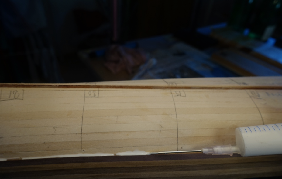
-
I can only agree Mark: perfect work. Thanks for your suggestion to enforce deck planks for shroud rigging. Regarding shroud fixation in the traditional ships, mounting in only one layer of deck planks is surely much too weak. I will probably come back to your suggestion when I am at this point (which will definitely take some time).
Clark
- fmodajr and marktiedens
-
2
-
I have started with the first hull planking. First strip of the first hull planking was tapered and glued. To fix the plank tightly to the deck line it was fixed using standard painter tape. I use painter tape very often to fix strips etc. since there are no residuals of glue when removing the tape. For keeping the strips tightly to each other, tape was used further on. For fixing the strips on the frames or on the filler, I made some small screw clamps out of 2 mm walnut wood. The screw clamps also helped to keep the bending at the stern.
- J11, stuglo, GrandpaPhil and 2 others
-
5
-
9 hours ago, fmodajr said:
Thank you Michael.
This kit is deceptive. On the surface, it doesn't seem that hard of a build, but the ship has many layers on top of layers (from deck up) and I have to be very careful to build in the correct order or layer. For instance, the plans call for building the upper bow platform over the cannon (in which I completed the framing). As I mentioned previously, I spotted blocks that needed to be added (later according to the plans). But how would I have gotten in there if I had planked over the frames I built?
Before I plank the finished frames above the carriages, I should install the cannon and the metal caps over the cannon pins. But if I install the cannon now, it will be much more difficult to place the intricate bow planking in front of the cannon because the front of the cannons would overhang, so i'll have to do the bow planking first. etc. etc.
I am slowly realizing that I can't just follow the order of the build that the kit instructions tell you to.
Having to keep thinking things through. But that's also the FUN part of the build
")
Thanks for visiting,
Frank
Hi Frank
First of all, thank you for your response regarding fixatiion and angle of foremast. I would fully agree with you that the fixation shown in the Corel plans is not strong enough. The plan of Fleur de Lis provides a much better solution. Meanwhile I tried to gather old paintings and drawings of this galley type but none of them really shows the way the foremast was fixed. I have finished a xebec last year with a very strong and multiple layered fixation of the foremast. I cannot believe that the fixatiion of the Reale foremast is much weaker than that of a xebec. Regarding the angle of formast in galleys, I found a mixture of perpendicular till almost 10 degree deflection in the paintings and drawings. Maybe one of experts in mediterrian ships may give some hints.
Hi Michael,
I have just started to build the Reale. It is really a challenge. But the excellent blogs of Frank and the others give you many hints. Moreover it makes really fun to think about the process as already mentioned by Frank.
Clark
-
-
12 hours ago, fmodajr said:
Hi Clark,
I am away this week. When I get home next week I will send you a photo of the foremast layout of the "Fleur de Lis" monograph. It shows the foremast mounted on the left or port side of the centerline. I will do the same. The Fleur de Lis plans shows only 1 hole going thru the upper deck. (The port side) NOT two openings as on the Corel plans. The opening is supported by a large knee built into the upper deck. It will be easier to explain once you see the detailed sheet. I have left room on the upper deck beams to be able to locate the hole where the foremast will go with a slight angle. I will figure the exact placement before I finish planking that upper deck.We'll discuss next week.
Thanks,
Frank
Hi Frank, thanks for answering such rapidly. Meanwhile I tried to transfer the foremast decline shown in the Encyclopédie of Diderot and d'Alembert grafic into the corel plans. Althought the waterline may be not congruent, it shows that the formast deviates 9-10 degree from the vertical axis (my degree digits on the plan are not correct, forgot to erase them). I think that deviation is necessary due to the special handling of the lateen sails. Similar deviation can be seen in xebecs and dhows. The upper left picture shows part of the Mondfeld plan of La Dracene with a similar deviation from the vertical axis. I do not know why Corel did not follow the old pictures but I think definitely that it is a mistake.
Regarding the fixation of the foremast in the main deck I cannot imagine that it is strong enough to counteract the enormous force produced by the big sail. The number of shrouds is also limited. In addition: one side of the bitt is open also weakening the fixation. Thus I am quite convinced that the plan of La Dracene is quite correct: fixation of the formast at the keel line.
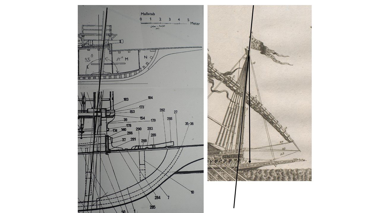
Do you know why the foremast could be both on the starboard and port side?
-
On 2/25/2019 at 10:57 PM, fmodajr said:
Hello!
I have started work on the main deck.
First was to install the forward and stern yokes.
Getting these two pieces right is important, I feel, because all the other deck supports will be positioned and aligned between these two yokes.
Trial fit of the fwd yoke

Trial fit of the stern yoke

Painted and installed yokes


Next was to make and install the 2 bitts near the bow.

The Corel plans show the beam in the photo below just laying on top of the 2 bitts.
This didn't look right to me. I check the plans on the Fleur di Lis (Gerard Delacroix) and it showed that the bitts were stepped into the upper beam. So I left the bitts 2 mm higher (as shown in the photo) and I will later notch that upper beam to accept the bitts
Finished Bitts, Painted and Installed.


Thanks for visiting,
Frank
Frank, when looking on the old plans, it seems that the foremast in galleys was not vertical but declined toward the bow. Did you calculate the decline when drilling the tubes in the bitts? The question arised when I was thinking about my best way to proceed. Morever, in the plan I saw, the foremast is fixed at the inner side of the keel. Thus there should be a hole in deck sourrounded by a support. Can you delineate that from your plans of the Fleur?
Clark
-
On 1/4/2020 at 2:31 PM, fmodajr said:
Thanks Clark,
Is this a book on the "Reale de France"?
If so, i'll try to find the book.
Thanks,
Frank
Hi Frank, the books shows and describes "La Dracène" (1675) but there is a table in the book on the cannon diameter used on galleys. As for the "Coursier", the cannon above the keel line: 36 pounds cannonball; 16.00 cm diameter cannonball; 290 cm length of barrel. // Cannons in La Reale: 36 pounds, 24 pounds (244 cm), 18 pounds (229 cm).
Link to a picture of La Reale can be found in my blog.
Clark
-
Deck is dry now fitted and glued. Filler blocks and frames were tapered again to follow the deck line.
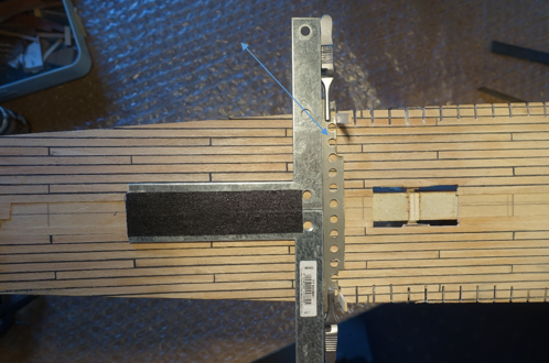
Deck was planked using the tanganjika strips provided by Corel. Unfortunately, I did not remember the difficulties, I had before with that type of taganjika strips. They are very thin (0.45 mm) and sanding has to be done with great care. Caulking is simulated by black paper (0.25 mm thickness) strips glued between the wood strips (Ratio width caulking/ width plank~1:20). After cutting the paper strips, sanding was first done in the direction from bow to stern to avoid darkening of the wood by dust of the black paper. Next the slots in the decks were cut.
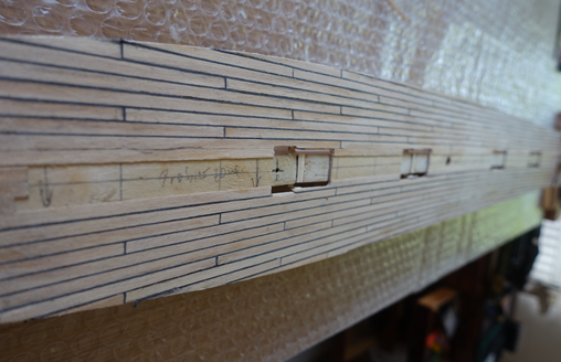
To cut the deck slots in regular intervals, a simple metal template with exactly 8.00 mm depth (=distance between the 1.5 mm slots, double arrow in the picture) was made. The metal was tightly clamped on the deck planking to avoid splintering of the wood when cutting the slots. As already said, the thin tanganjika wood is tricky. Rectangular fit and congruency between starboard and port side was controlled by a rectangular metal.
Meanwhile I got a hint to a picture of the old Reale. The ship is described in the Encyclopédie of Diderot and d'Alembert, an ancient voluminous Wikipedia. There is so called “planche” showing La Reale.
Link: https://www.e-rara.ch/zuz/content/pageview/7088914 .
Although this might not really help in building the model it gives an impression how the ship was handled and flagged. I am still wondering how the war prisoners (oarsmen) were treated. Did they have to stay at the oars day and night?

- GrandpaPhil, fmodajr, JayCub and 1 other
-
4

Reale De France by fmodajr - FINISHED - Corel - Scale 1:60
in - Kit build logs for subjects built from 1501 - 1750
Posted
Frank, which kind of paint do you want to use? Water based paint would not work, I assume. May be better to use Humbrol or any other enamel paint. But I am not sure if the sanding procedure proposed works together with this kind of paint. Any experience?
Clark