Piet
-
Posts
3,568 -
Joined
-
Last visited
Content Type
Profiles
Forums
Gallery
Events
Everything posted by Piet
-
 Hey Jeff, Thank you very much for your kind words re my father. Yes, I know he served with honor. I'm sure he'll like this model and it means much more to me then any other ship model I could build. Stop by again, please. Cheers,
 -
Thanks for dropping in Jim. Yes, it's coming along except for the minor setback with the center keel frame. There are a few things I need to take care of though, the warping problem with the poplar wood, but I have figured out a method to prevent it from happening on the actual build. More info coming soon. @ Peter, Yes indeed, they were trying times for us. Being a "guest" of the Emperor of japan was no pleasure. What camps did your parents have "the pleasure" to be in? I spend the first 9 months in Darmo Wijk, Surabaya, then most of the duration in Muntilan, formerly known as Moentilan, Central Java, then Banjubiru (Banjoebiroe), then Ambarawa camp 6 and Machalang. But here I am enjoying life and retirement in sunny Florida being part of a tremendous group of friends from all over the world. Priceless! I'm following your Zeeschouw build, looks very nice. Cheers,
-
Hey Sjors, I thought to stop by for bakkie leut and a koekie and say hello. Very nice work my friend! The planking looks great from here, seems you are catching on. Everything looks just peachy. Cheers,
-
Hello Peter, Nice looking little boat! I also love these old time fishing boats and hope to build a model of a botter or schokker sometime in the future (if I live long enough . Have seen many in years past when still living in the Netherlands. Mine will be scratch build though and a larger scale. Your model is really taking on a nice shape I'll look over your shoulder as you progress, brings back memories. Cheers,
-
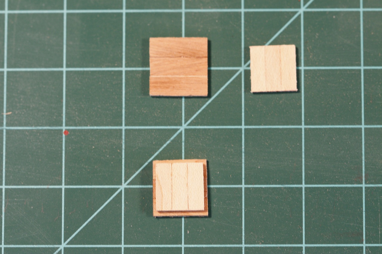
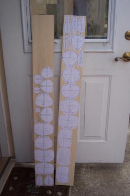
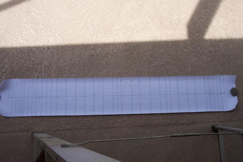
Center keel frame splice and build up with reinforcing blocks. The center/vertical keel frame is from ¼ X 4X 36 inches. This was not quite long enough for the ¼ inch thick part so I needed to spice in a piece, he figured So, I first trimmed this plank to 79 mm wide and then cut it in half. Great so far. Next I cut a small piece to splice in and spice plates from ¼ plywood. I glued and clamped everything to together with TiteBond and put the whole assembly in the dock keel. Fit great! Next I cut and glued ½ X ¾ inch blocks of pine to the vertical keel frame to prevent it from warping and to glue the bulkheads to for additional stiffness and for a true vertical guide. The following morning I removed all clamps and checked how it all looks. To my great dismay the center keel frame has a bow in it at the rear spice. Not a good thing. I tried everything possible to straighten it out but nothing doing. What happened was that the splice plates warped and bend the center keel frame. First I removed these splice plates and replaced them with oak, thinking that’ll help, but no dice, same thing. I was one ticked off dude. So, I ripped everything apart again and threw it on the scrap heap. Well actually I can still use a lot of the wood for small stuff and possible planking. Off to the store and bought a new piece of poplar. Fortunately it’s not expensive wood so I don’t really loose that much. It’s nice wood but very prone to warping and I have to constantly wet it down and put weights on it. This time though I am not going through that experience again and will splice in the thinner pieces for the bow and stern. Don’t know yet from what wood, if I have enough boxwood of the proper dimensions then that’s going to be it. It needs to taper from ¼ inch thickness to 1/16 and needs to be rather sturdy. If I can’t find what I need then a message to Jeff Hayes. I also copied the bulkheads on a few sheets of paper, cut them out and pasted them to ¼ X 4 X 36 inch poplar wood planks. Well, that’s it for now. The center/vertical keel frame splice being glued up with the bulkhead support blocks. Looking great, so far. I didn't make a picture of the disaster but onward we go and try to prevent it from happening again. Kinda hard to tell how long this model actually is. The shelf openings of the workbench are 21 inches. Bulkhead templates glued to the 1/4 inch plank, ready for sawing them out. I may have to add e few frames where the space between them is too large. Cheers,
-
Hello Yambo and welcome to my build of my father's submarine. A little bit of living history. Cheers,
-
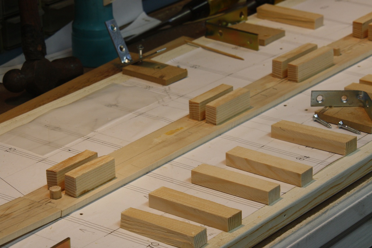
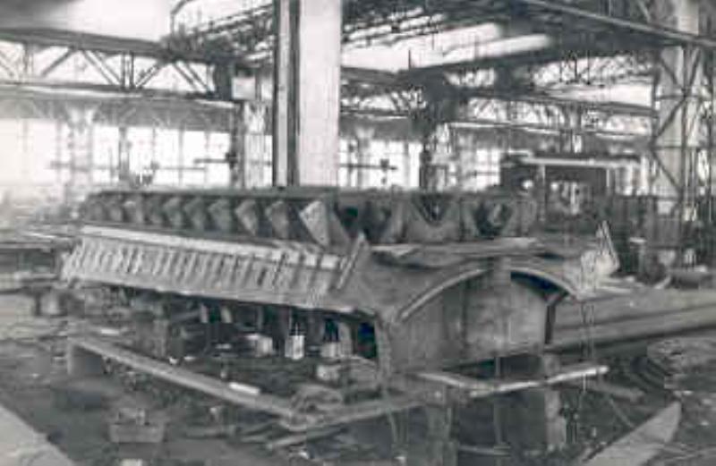
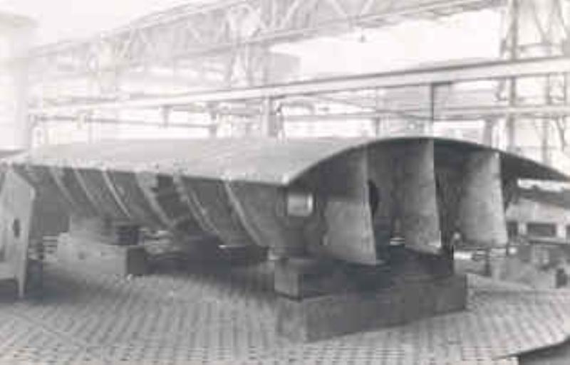
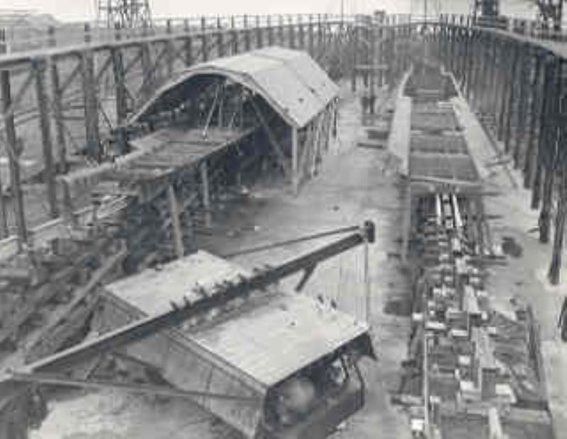
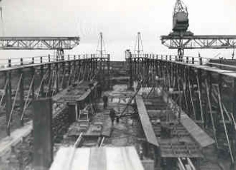
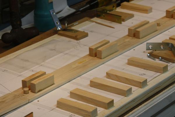
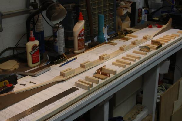
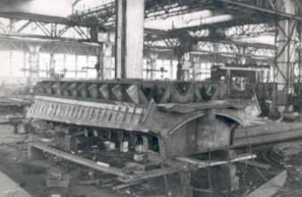
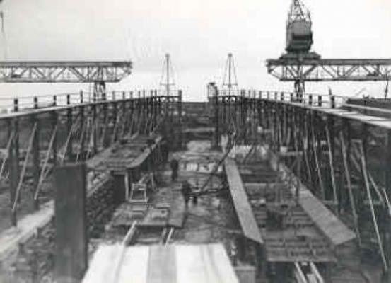
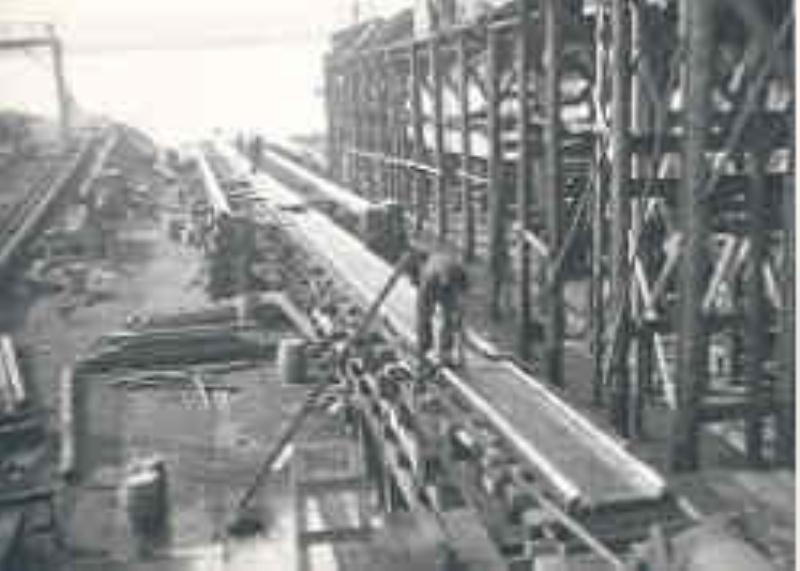
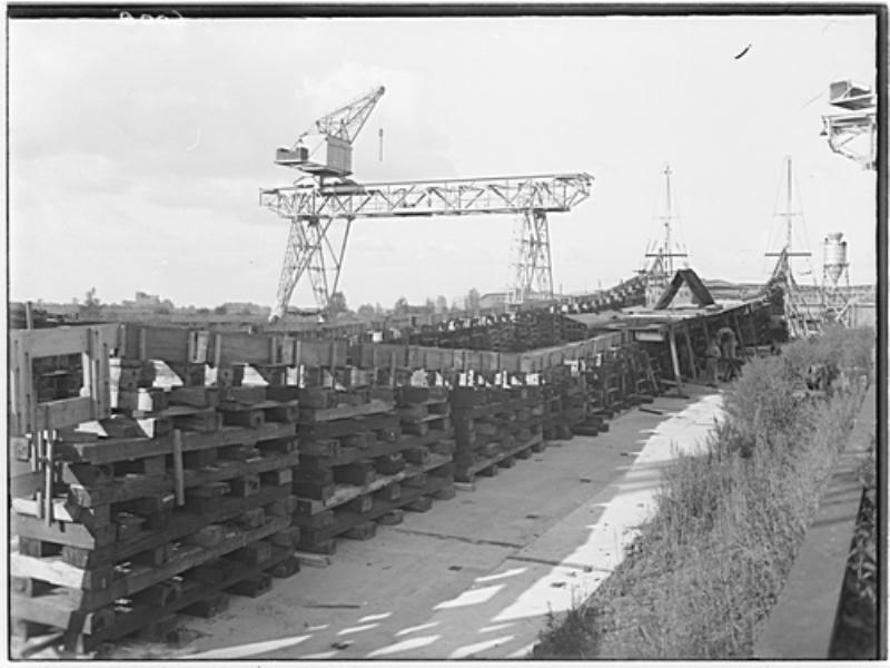
LAYING DOWN THE KEEL. I cut the separate sections of the keel from a ¼ inch poplar plank per the dimensions from my drawings. The so-called “dock keel” and the first aft part next to it are chamfered 10 degrees with the narrow part facing down. All others will be flared as necessary when the bulkheads are installed. At least I have enough photographs from Wilton Feyenoord, the builder, to come to a close approximation. The narrow and curved bow and stern keel pieces I have soaked in water and then bend to shape in the build dock. This worked great and eliminates a lot of strain. As mentioned in a previous post, the dock keel and forward and rear sections are heavy assemblies of several parts that not only house the lead ballast but also the water ballast and trim tanks. I will add a few of the original photos for clarification. In order for me to fasten the vertical keel frame centered to the dock keel I glued ½ by ¾ inch pine blocks to the keel, making double sure that they are parallel to the centerline with a ¼ inch space between. I also drilled 3/8 inch (9 mm) holes through the dock keel and into the build board for 3/8 inch dowel pieces. This is so I can remove the model any time and it will always come back in the same spot on the build board. Dock keel laid down loosely and pinned. Stiffener blocks are at the ready for the vertical keel frame and doubling as fastening support for the bulkheads. All keel pieces are loosely laid down on the keel dock. This allows me to transfer the shape to the vertical keel frame for cutting. Keel assembly made by Wilton Feyenoord. Part of the keel assembly by Wilton Feyenoord. Part of keel assembly by Wilton Feyenoord and overall picture of laying down the keel assemblies. This pictures the laying down of the keel assemblies for the O 19 and her sister the O 20. Cheers,


-
Hello Jan and Carl, Thanks for finding this build and yes, please follow along, it's different. Yup, I have finally started with my father's sub. Had to get all my ducks in line first and thanks to Remco he has been able to obtain copies from the original drawings. Challenging? Yes, in a way but more emotional, knowing that he was involved with the final six months of the build. He didn't endear himself with the boatbuilder though because he wanted inferior work redone. But that's another story. It'll be slow going though because I still want to devout some time on the VOC ship. Cheers,
-
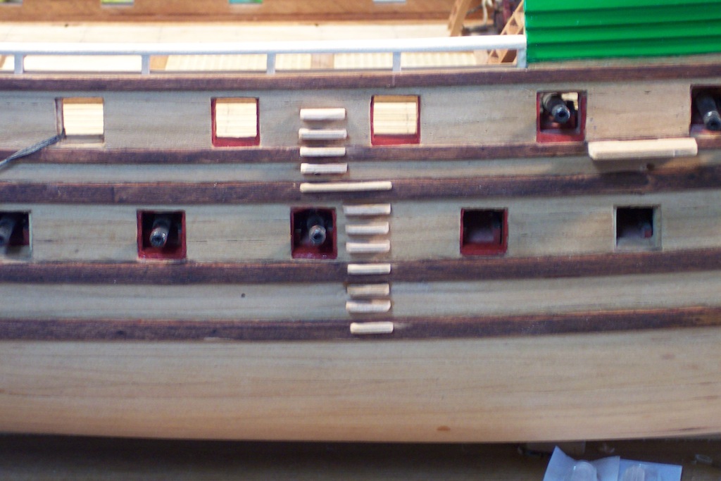
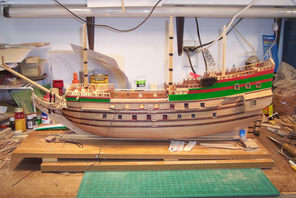
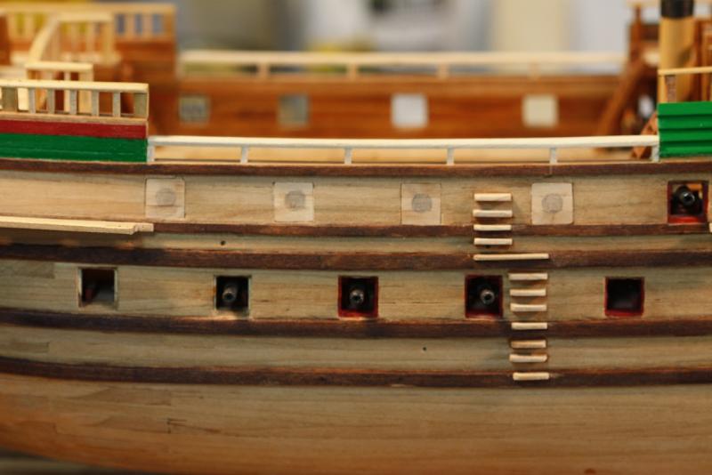
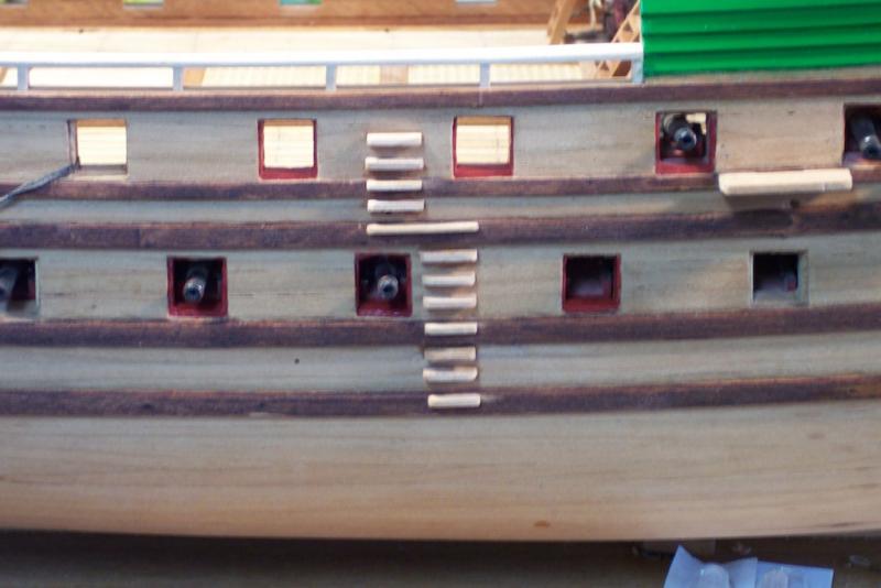
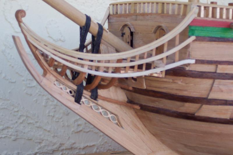
In the meantime I made the outer parts for the gun port lids and am about ready to glue them together. Then the pull cord eye bolts, and hinges. The inner planking is 10 mm square, the outer planking is 12 mm square. Both give or take a fraction. The last photo I tried something. I wanted to see how it would have looked like to just have round port holes for the smaller guns instead of the larger square holes with lids. In retrospect that’s what I should have done, I think. But it’s too late now to make a change and I’ll have to leave it this way. It does kinda fit my original idea of making this a hybrid ship, a heavily armed merchant vessel. I’m also still pondering whether I should paint the railing in the waist green to have a continuation of the green color between the forecastle and the aft end. I think it would look better. Any ideas, suggestions?? Gun port lid parts Gun port lids in gun ports for a look see Cheers,

-
Hey Sjors, Thanks for the pics and a lion with flowers on his head? Rather dainty isn't he? The second on looks rather fearsome, very nice indeed. I could use the head on the body from the one on the Batavia Jan send! Or perhaps it's the same one? Hi Jan, Wow, yes, I remember seeing that one, good looking. Like I mentioned above, I may just use the head from the one Sjors send on the body from the Batavia or the drawing from van Ijk. Need to make a few sketches and see what falls out. Needles to say I have my job cut for me (pun intended ) Thanks again for your help Cheers,
-
Hey Sherry, I've been sneaking a peak now and then. Sure hope your brother and daughter are doing well!!! All I can say about your work is, - - - how sweat it is! Take Remco's admonition at heart, "treat each part as a complete model" then you can't go wrong. One small piece at a time. Love your scroll saw too. I have a Proxxon and jewelers saws as well, use them a lot for all the small stuff in my scale. Looking forward to your progress. Cheers,
-
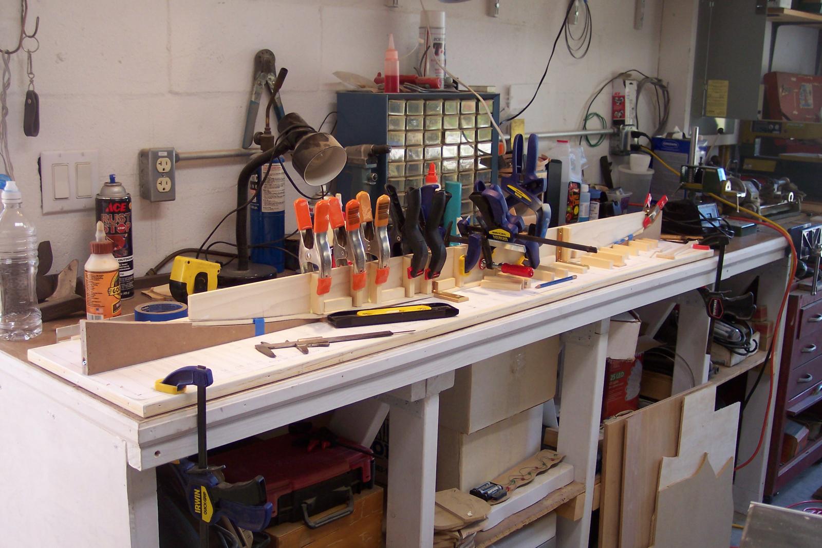
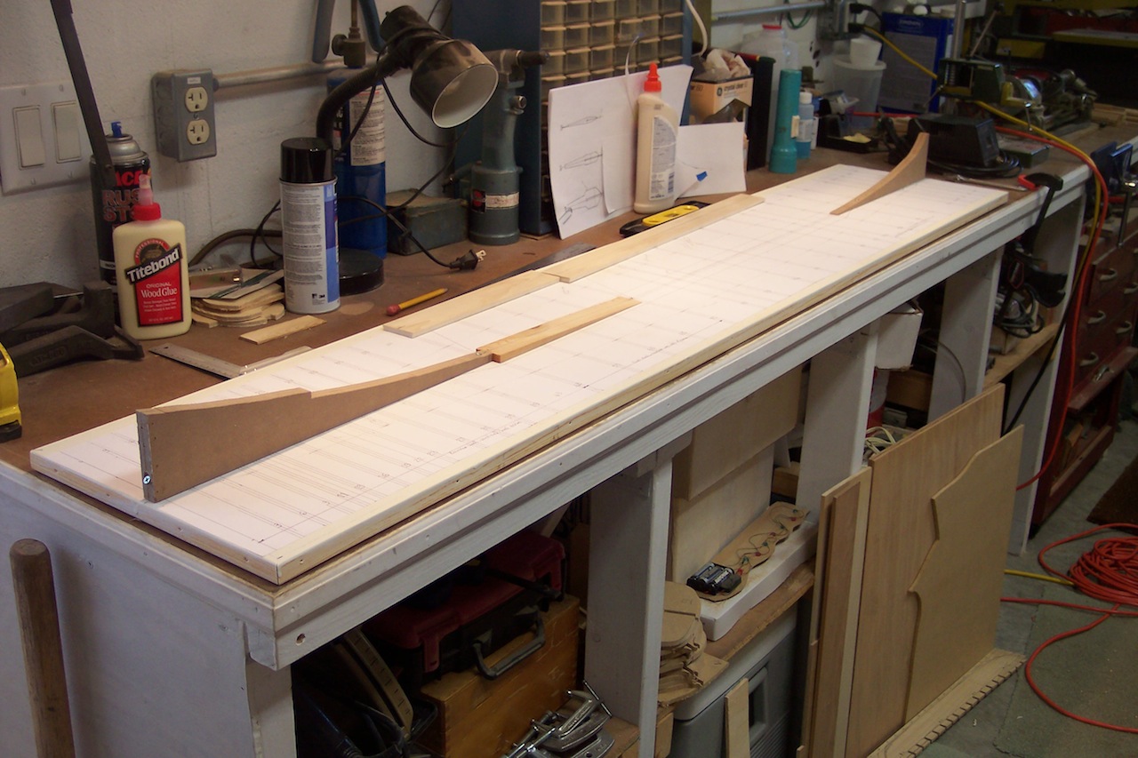
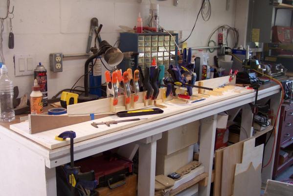
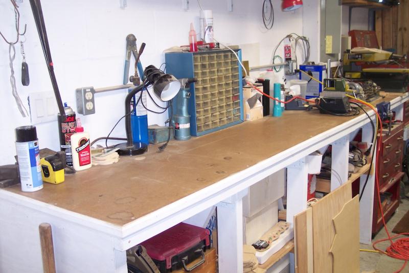
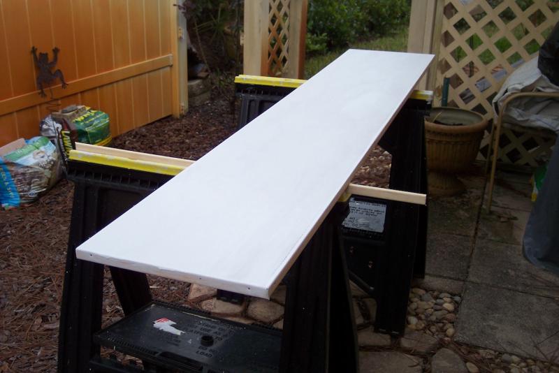
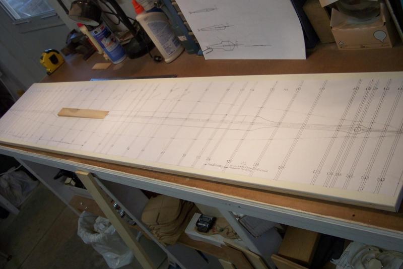
THE BUILD DOCK Well, now’s the time to start the preparation for the build dock and it’s fabrication. First I needed to make space on my home made workbench on the North wall in my garage. I moved my DB200 Unimat lathe, Proxxon drill press and solder station towards the east end and then double-checked the workbench for level. It still is! (pic 1) I cut a ¾ inch thick piece of plywood to 12 X 65 inches for the keel dock. Sanded, primed and painted it. I even screwed some nice edging to the sides. (pic 2) Then glued the keel/bulkhead layout on top. (pic 3) As can be seen in the keel layout drawing only a small portion is parallel to the waterline. (see previous post, Drawings). This is called the “dock keel,” which is a rather complicated and heavy box structure. This keel box consists of three compartments where the two outboard ones are filled with lead ingots for ballast. (See future pics) The forward part of the keel has a nice curve upwards that runs into the rounded bow. (see previous post, Drawings) The aft keel starts with a flat keel structure similar to the dock keel but angled up then going over into a smooth upward curve towards the stern end. (see previous post, Drawings) I made the keel supports forward and aft of the “dock keel” from MFD cut to the drawing curves and screwed to the plywood build board. (see pic 4) I have added the actual photographs from the boatbuilder to show how it was done for real I intend to install two dowels in the plywood build board that’ll secure the “dock keel” in place so I can remove and reinstall the hull later when needed always being sure that it’ll go back in it’s place. (see next post). Workbench for O 19 model build. Build board being prepped Build board with keel/bulkhead layout Completed model build dock. Buildup of keel dock for Hr. Ms. O 19 in 1936 Keel dock nearly completed for Hr. Ms. O 19, 1936 Keel dock completed for Hr. Ms. O 19 in 1936 Cheers,


-
Hey Remco, Just marvelous! It's a joy looking at it. I showed it to the admiral too and wow. Cheers,
-
Thanks for the pics Dirk, I can use the Witsen lion okay, looks very nice and with his tongue sticking out too! Wonder if he is doing that against the English Some modelers put the tail on each side, left and right, just to make it look similar. Hey Anthony, a root canal is minor stuff, believe me, I have had many done and all of them were a breeze. They numb you and pull the nerve out, disinfect the hole then put a pin in it and the crown or whatever. Stay away from amalgam, that's mercury and no good for your bod. Re the model work, it'll slow down a little now that I am working on two models and the admiral needs more of my attention due to her bad back. We just celebrated her 72d birthday And yes, I'll be rigging it with sails! Cheers,
-
Hey Marc, thanks for looking in and your encouraging comments. Flying Dutchman 2 eh? Are you a pilot also? That's what many folks in the past labeled me, I used to fix them, design repairs for them and flew them. The title kinda stuck. Besides coming to the USA way back in 1957 from the Netherlands. In any case, yes, I love these ships, they had character and made a tiny nation the greatest seapower in the world before England overtook them. The Valkenisse, beautiful ship and like to see you get started on that project. How soon? Cheers,
-
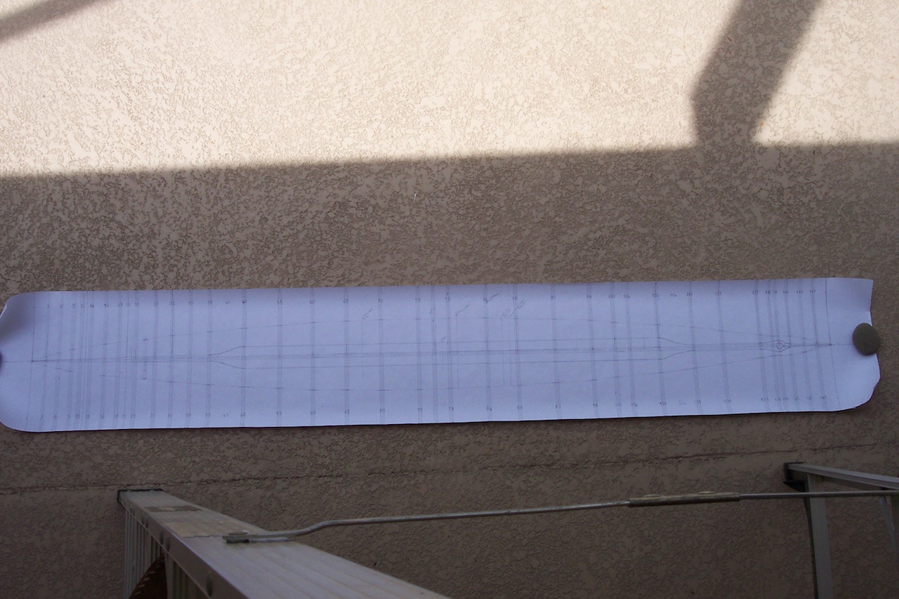
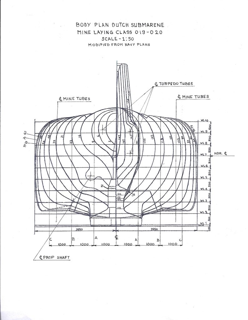
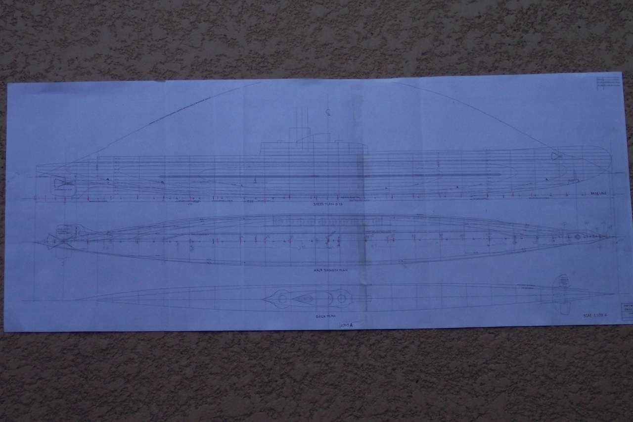
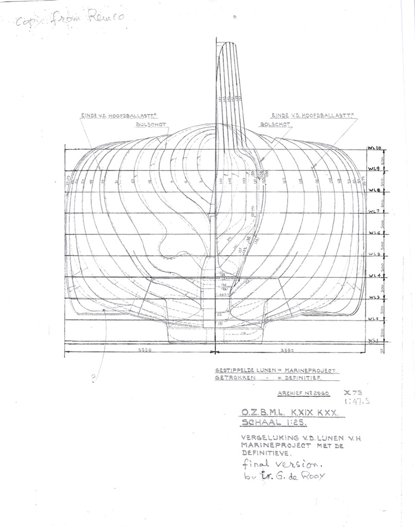
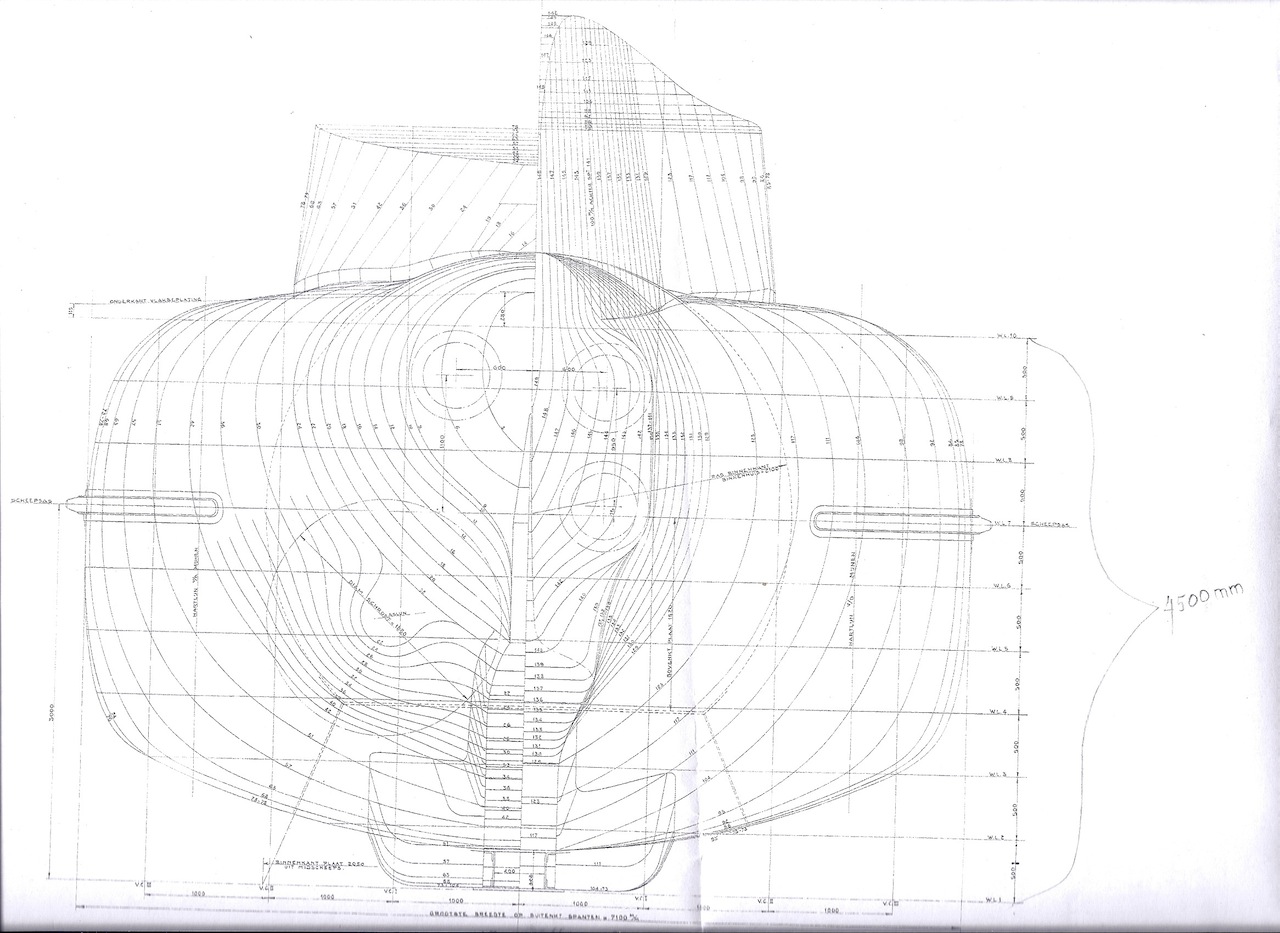
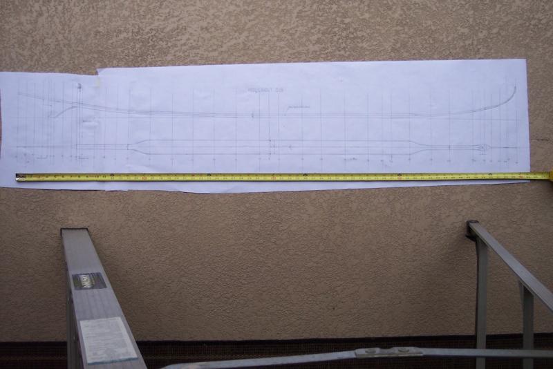
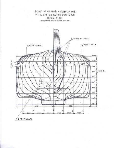
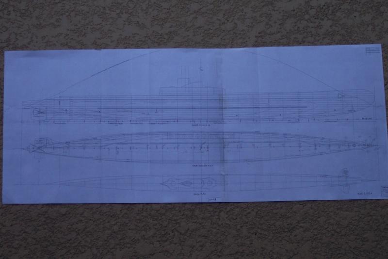
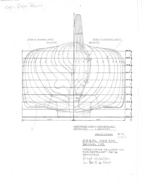
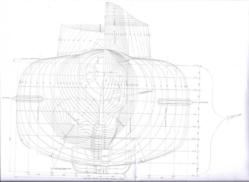
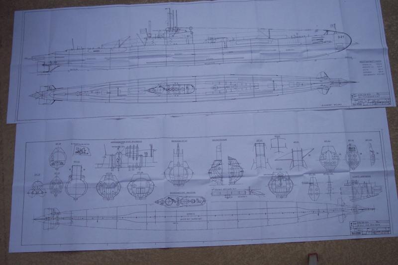
DRAWINGS In my search for drawings I learned that none were available for the O 19. First I contacted Wilton Fijenoord, the builder of the O 19 and O 20, via e-mail who told me that all their build drawings went to the Royal Navy Archives in Den Helder, the KM Navy base. I tried several times to get in touch with them and the Museum but received no answers. I mentioned my dilemma in my VOC build log and Remco contacted me via PM with a URL that had model builder drawings for the O 21 and also for the cruiser HR. Ms. Java, the ship my father was killed on. Great, so I went to the URL and I tried to place my order for these drawings but their invoicing did not accept my order. Hmmm, perhaps they don’t like Dollars, I thought and I can’t blame them. Now what. I wrote my wife’s brother in law who lives in The Hague and asked him if he could buy these drawings for me and I would reimburse him for the costs. He informed me that these drawings were no longer available because they were in the process of digitizing them and would take a few years. I mentioned this to Remco and he offered to try from his end to purchase the O 21 drawings for me on a PayPal transaction. Well, he hit pay dirt and snail mailed the drawings to me. I figured that the O 21 may have been build along the same lines as the O 19 with the exception of the external mine compartments. I could kinds, sorta, figure out the shape of the hull by looking at photographs and use the dimensions of the mines to get the approximate shape. Well, later on I learned that there were more differences that would make my attempt not really look exactly like the O 19. For one, the O 21 is a little shorter. I didn’t know that yet so I continued my research in what mines the O 19 could carry, what the dimensions are and how many and where exactly on the hull. In the meantime Remco did a lot of research himself and found that the original plans were archived in the KM Archive in The Hague. One could order any amount of drawings and they would print them out for € 10 each! Ouch! But - - - they could not do that for the foreseeable future because they were in the process of digitizing the microfilm records. Remco didn’t give up and “sweet talked” them into allowing him to come to the archive and make his own copies. I have a sneaking hunch that by mentioning my father may have softened their hearts. So, Remco went to the archive and was able to find the drawer of the microfilm for the O 19 and copied the most essential drawings for me, three versions of the body plan, the sheer, waterlines and half breadth plan, deck plans, interior layout, and mine compartment structure. In addition to finding the drawings for me he also found a URL that had many actual photographs of the construction of the O 19! I could download many and these too will be a great help in visualizing the shape in many areas, specially the bow and stern. Hurray! With these drawings and the O 21 drawings and photographs I could now build a model with a high level of confidence that it would look as my father saw it and sailed on it. I only had to change the scale of the drawings and redrew them to my 1:50 scale. Well, actually the final version of the body plan, archive number 2960, I could manipulate on my HP printer to the size I needed. All the others I had loft by hand on the floor in my studio. She’ll be a big model and the Admiral asked me “where are you going to put it?” “I’ll find a place my sweets,” I responded. End of conversation, she knows how close this is to my heart. We both have seafaring fathers and Navy men. “Oh, buy the way”, she asked, “when are you going to make a model of my dad’s ship”? “Which one, the one he made captain on in 1953 (M. S. Musi) or the one he was on when the JIN took it in March of 1942 (SS Duijmaer van Twist 3)?” I asked. He was at that time of the war a Lieutenant Commander in the Navy Reserve with the MLD (Navy Air Arm) and was ordered to report at the MLD base Kamayoran but subsequently ordered to report to Cilicap (formally spelled Tjilitjap), the southern Navy base. Kamayoran no longer exist and that section is now called Kecamatan Krembangan, in case any one wants to look it up on Coogle Earth. He was to join 300 or so military personnel as well as civilians and take them to Australia on the KPM ship “SS Duijmaer van Twist.” On the way south the JIN took this ship on 3 March of 1942. All personnel on board were taken off and made POW’s. The crew remained on board to work the ship for the Japanese who renamed her Dai Maru. She was sunk by a US bomber attack on 14 May, 1945 . “One of these days dear.” ;-) All the drawings are now made and I drew up the necessary bulkheads, keel and center vertical keel frame. It’s now just a matter of transferring it to wood, but first I have to build the build dock. This will be a piece of ¾ inch plywood 65 inches long by 12 inches wide, which should give me enough space for jigging and measuring equipment. It also needs to be primed and painted. I’ll glue the keel and bulkhead layout drawing on top of this nicely white painted board. I checked the workbench again for level and confirmed that it was still level both ways. (pics of the drawings with explanatory text) TECHNICAL SPECIFICATIONS FOR SUBMARINES O 19 AND O 20 Boat O 19 O 20 Pennant # P 19, N 54 Type Submarine minelayer for operations in home waters as well as in the colonies. Class name O 19. Named after first of class. "O" stands for "Onderzeeboot" (submarine) Laid down 15 June 1936 15 June 1936 Launched 22 Sep 1938 31 Jan 1939 Commissioned 3 July 1939 28 Aug 1939 Refit Feb 1943 - Feb 1944 - Fate 10 July 1945 scuttled 19 Dec 1941 sunk/scuttled Other names K XIX K XX (hit by mine) Design Dutch design by ir. G. de Rooy. Possibly (but not confirmed) based upon the Orzel class which was designed for the Polish Navy. Shipyard Wilton-Fijenoord, Rotterdam Le x Be x Dr 80.70 m x 7.41 m x 3.87 m *Le: W-line 80.700 m *Le: Max. 80.870 m 80.70 m x 7.41 m x 3.87 m *Be: Max. 7.411 m *Dr: Trimmed: Fw. = 3.620 m, Mid. = 3.870 m, Aft = 4.120 *Keel to: Scope wavebraker = 10.75 m, to RDF mast = 15.3 m Displacement Stnd/Surf/Subm ex K XIX / K XX : 1015 t / 1145 t / 1561 t O 19: 982 t / 1109 t / / 1491 t Displacement *Norm: 1116.464 m3 (1145.492 t ) *Subm: / 1561.083 t *Stnd: / 998.542 t (1016 Kg) *CM: / 3850 m3 (3950 t) Volume *Net: 1302.598 M3 (460.282 t) *Gross: 308.550 M3 (109.028 t) Engines Two 7-cylinder Sulzer diesel engines, 2-stroke, 2 x 2650 apk (shaft horse power) Motor Two 500 apk motors Batteries 2 x 96 cells. 5300 Ah during 5 hours. 6000 Ah total *Power grid: 175 - 260 V *Light grid: 175 V Snort 'First' class in the world equipped with a snort system, see notes Shafts 2 Speed surf/subm 19.5 kts / 9 kts Range surf/subm 10000 nm at 12 kts / 27 nm at 8.5 kts Depths *Diving: 100 m *Periscope (flush): 15.5 m (15.2 m) *Launch: 25 m Diving: 100 m Water *Drinking: 8567 ltr. *Washing: 12350 ltr (6825 m3 in AHB tank) *Distilled: 1400 ltr. not for battery and 1490 ltr. for battery Complement 40 Torpedo tubes 4 x 21" bow, 4 x 21" stern Torpedo Type O 19: Mk 8, V53, Mk IV*SD O 20: IV53, V53 Mine tubes 2 x 10 external shafts amidships on each side. Using the French Normand-Fenaux system. Each shaft contains two mines (above on another). Mine type Vickers (199 stocked in the N.E.I. in Feb. 1942). On 13 Apr 1945 she laid a line of Vickers T III T mines. Armament 14 torpedoes, incl. 6 reloads, and 40 mines Guns 1 x 8.8 cm / 45 AA. (*#3, Mar*#7) with *125 shells 2 x 40 mm Bofors in single 'disappearing' mounts, in watertight wells forward and aft of the conning tower. 1 x 12.7 mm AA. *Oerlikon 20 mm II #S9195 OLK 126 IFF 47041 #S17707 OLK #16 5W 28620, OLK 8643 .116.'6 72455 *Forward watertight well and machine-gun possibly removed during the 1943-1944 refit. Small arms *Vickers 7.9 mm, 0.303" GO #1, 1 type A, #3365, $33529, #34692 *Sub machine gun Thompson aka Tommygun 45 c 8.8 mm, 296305, 105333, 14491 mod u.o. 1941 *Automatic rifles B3896, B5329, B5470 *Pistols #1 Automatic 2B66, 3B67, 2B68, 2b69, 2B89 #3 Automatic Colt Automatic Weble & Scott Ltd #2 Mk1 7041 and #1 Mk1 28620 Semi Gogswell & Harrison Ltd. 72455 Sonar Equipped with a geruispeiler (listening device) from Atlas Werke (Bremen). In those days 'Atlas' was the best on the market. ASDIC *120B RDF *Type 291 * SPEZ.1000N II (2) # V/38033. TEL. E305N NO 67006 - 36 Fr: 1666 kc (180 m) - 75 kc (4000 m) 33.3 kc (9000 m) - 15 kc (22000 m) IFF *Possibly type 251W Echo sounder *Hughes & Son, ADM Pattern, universal type Log *SALSEL SYNLOG #4364 Radio *Transmitter: NSF svc 800 L /20, #4353/2 Fr: 15000 kc (20m) - 2500 (120m) Pw: 800 W A13, 240 W A2 and A3 Seinw: A1, A2, A3 Supply: 175, 260, 3000 *Transmitter: NSF svc 200 L /30, #4353/1 Fr: 750 kc (400) - 250 (1200) Pw: 200 W A13, 60 W A2 and A3 *Receiver: NSF MO 11/12 L/354 Fr: 14.27m = 20700 kc, 66.7 kc = 4497 m Fr: 9000 m = 33 kc, 15 kc = 22000 m Supply: AC 220 V ~ (kva), DC *Receiver: Nat. comp. USA, HRO (standard) #94B Fr: 10 m (30000 kc), 177 m (1708 kc) *Receiver: AR88 Fr: 32 - 0.535 mH Supply: AC 100 - 260 v ~, DC *Receiver: 13.29 Fr: 15 - 550 kc Supply: AC 220 v ~, DC *Receiver Amusement: 296A, Philips #3824 Notes - Often regarded as the first submarine class in the world equipped with the "getrimd diesel systeem" or "snort system". Also check the O 2, K II and O 16 class details for info on even earlier Dutch snort systems. - First Dutch class for use in home waters as well as in the colonies. After this class the distinction between 'O' boats (for home waters) and 'K' boat (for the colonies) was not used anymore. - ?Partially double hull? * = Source for this data is a WWII (possibly post 1943) personal notebook from an O 19 officer. Hr. Ms. O21 model builder plans for O 21 Model of Hr. Ms. O21 Navy Project O 17 to build a mine lying submarine, 1934. Final version design by ir. G. de Rooy in 1935. If you squint real hard you can see the dashed lines of the original Navy plan. Sheer, half breadth and deck plan for K XIX and K XX My resized body plan to scale 1:50 My lofted keel layout to the scale of 1:50 Build board keel and bulkhead layout to be glued to the build board. Cheers

-
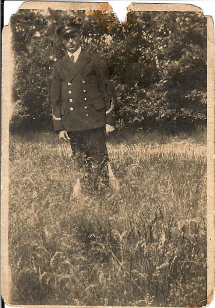
Thank you gentlemen for your kind words. And John, I am corresponding with two fellows in Australia and received a few pics of the memorial in Fremantle. Another fellow is the diver/photographer who took pictures of the wreck of Hr. Ms. Java and have now a "grave marker." This build has been a long time desire and at last I have the opportunity to build my dad's beloved boat. By the way, the picture of my father in my previous post is when he was a boatswain, way before he got married to my mother. This must have been in the late twenties. It's only one of the three pics I have of him. More stuff coming soon. Cheers,
-
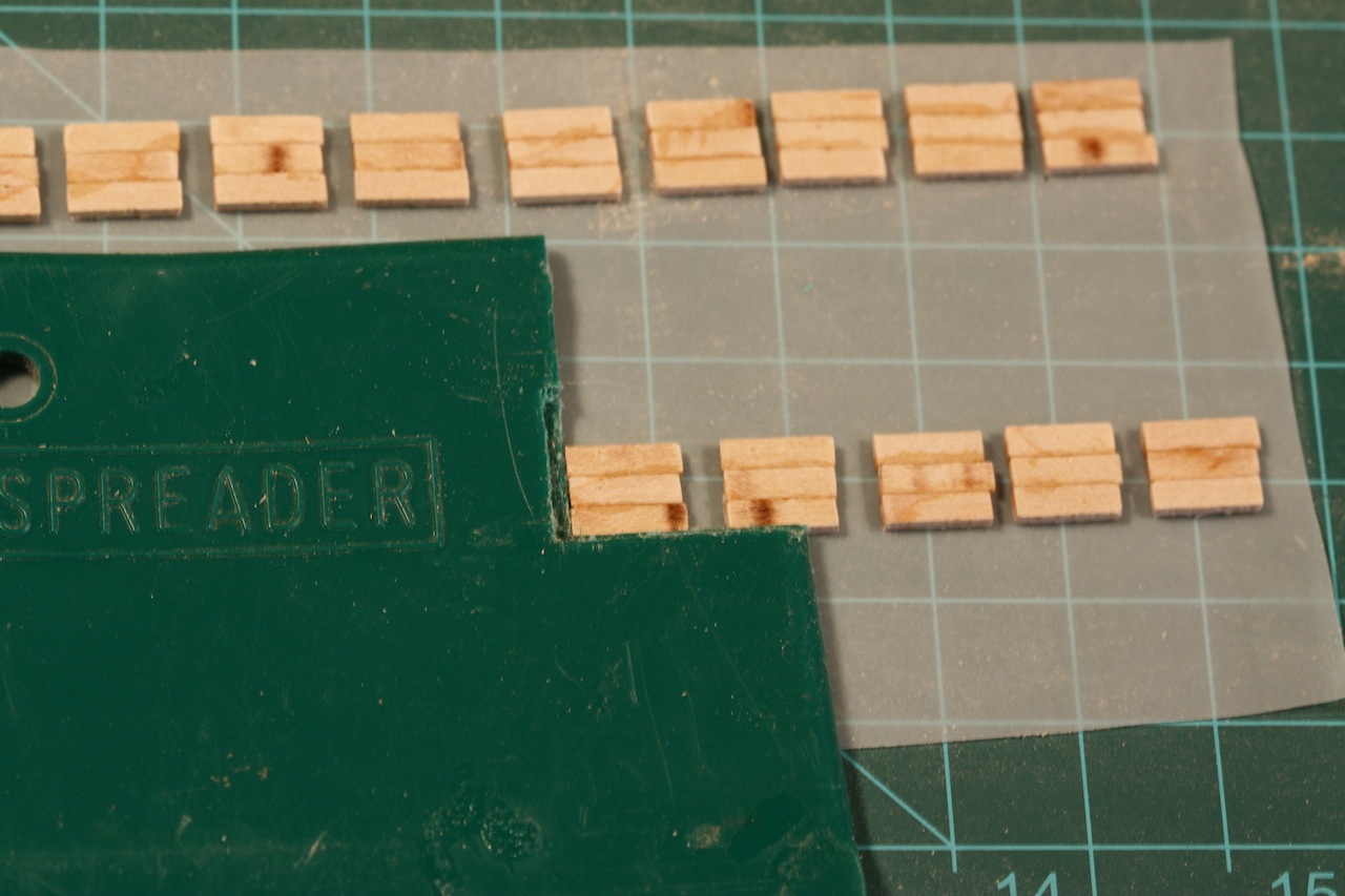
Hello all, Well, as mentioned just a few minutes ago here is a picture of the gunport lid action. I made a jig from a plastic putty spreader I had in my toolbox from de days I was actively engaged in aircraft repair. I cut a small 90 degree opening in it to hold the small pieces of maple square. The inner planks are 1 mm thick by 10 mm long and I need three for each lid. I glued then edgewise with CA. I was smart enough to make them a little larger so I can shape them nice a square and they also need to be made a little thinner. The fixture also accommodates the outer planking of cherry but I'll use regular carpenters glue for that. I'll try to make the hinges from brass sheet and brass pins for hinge pins. Hmmm, then the tiny eyebolts closeup of inner planking for gunport lids. Cheers,

-
Thanks for your approvals Dirk and Jan, really appreciate it from the "Heren 17" Yes indeed I'll be carving a lion. The ship just wont be complete without the Dutch lion! I need some examples to use for that project though. Pictures are welcome so I have a choice. Am working on the gunport lids right now, 32 total Cheers,
-
Niiiiiiiice! Did you cut the camber in or did you heat-bend it? I assume the mortices are hand cut instead on your milling attachment. Just lovely! Cheers,
-
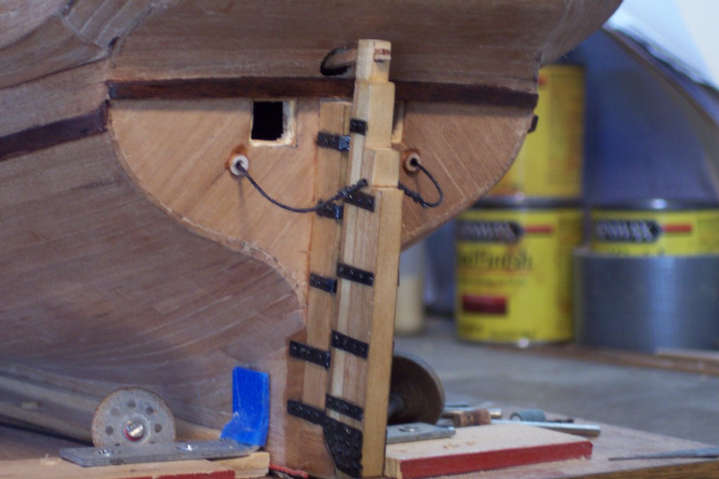
Thanks Mark and Daniel for your words of encouragement regarding my jaw. Truth is that I had very little discomfort with it all, and that's a good thing. The VOC ship is taking a backseat right now because of all the prep work for the O 19 sub log. However, I am picking a little here and there at the VOC ship. I installed the outside steps to the hull and the rudder securing cables. Next will be making the gunport lids. I need to fabricate a jig for it so I can make them assembly line fashion. I cut the wood already for them but the strips need to be planed thinner before I can cut them to the desired lengths. I have a lot of "shipyard rash" to fix up and clean I see before I can put the Danish oil on the hull. Okay, here are a few pics of what I have done in the last week. Close-up of rudder securing cables installed Close-up of boarding steps. Port side view of hull Cheers,


-
Hey Remco, Thanks for your kind words. And of course also thanks for your help in obtaining the needed drawings! Yes, they were tough times for us but I have many good memories from the times before WW II with my hero dad. I hope that this log may add a little more knowledge of seemingly insignificant events in world history. Cheers,
-
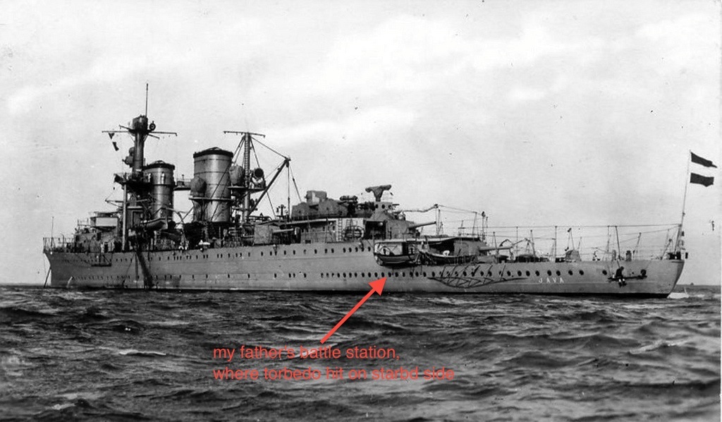
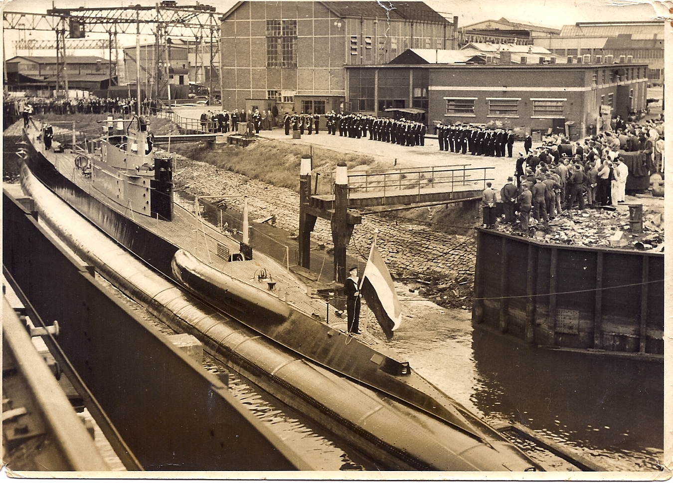
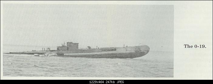
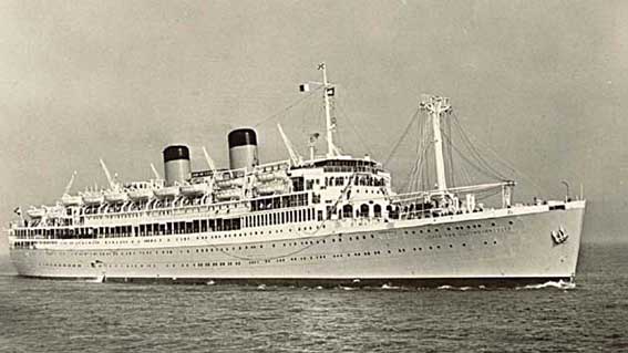
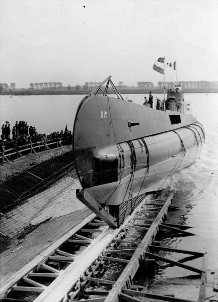
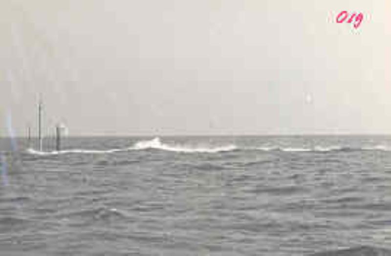
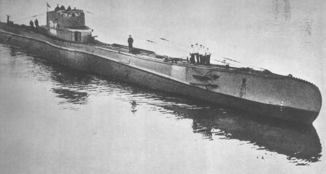
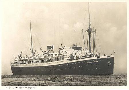
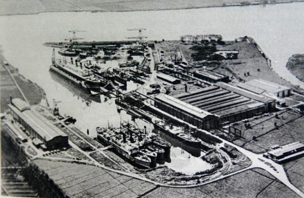
INTRODUCTION This is the build log for Hr. Ms. O 19, one of only two submarines in her class of the Koninklijke Marine (Royal Navy). Please forgive me for making this introduction very personal because she was part of my life and therefore holds a very special interest for me. My father, Opperschipper (Adjudant) Petrus W. van Warmerdam, was with her from about one year before her launch September 22, 1938 till his promotion to Opperschipper in January 1941. At the time he was placed on the build he had the rank of Schipper, with the added function of Quality Control and Assurance Inspector and liaison between the Navy and the ship builder Wilton-Fijenoord in Rotterdam, the Netherlands. His second tour of tropical duty started right after his marriage to my mother in October 7, 1931, and they started a family while in Surabaya, the former Dutch East Indies. My sister and I were born there, November 14, 1932 and April 15, 1934. When his second six-year tour of tropical duty ended in the end of 1937 he had to return to the Netherlands. Of course his family, my mother, sister and I, followed shortly after on the passenger liner M. S. Christiaan Huygens of the Stoomvaart Maatschappij Nederland, Amsterdam. When we arrived in the Netherlands we first stayed in Den Helder, the Royal Navy Base, but after hearing about the new class of submarines being build he immediately requested to be placed on them. Because of his expert technical knowledge of submarines the Royal Navy agreed and he and his family moved to Vlaardingen Ambacht, Narcisplein 3 to be exact, a small town near Schiedam, in March of 1938. Sjors and Anja know this area quite well. The shipyard was located in Schiedam, the Netherlands and the boat he was assigned to happened to be the furthest along of the two in that class, mine laying submarines. The original design concept for a mine lying submarine was completed in December, 1934 and assigned numbers O 17 and O 18. (Reference pictures can be found in the DRAWINGS section) However, the design was altered to a more squarish form amidships for better loading and discharging of the mines by engineer G. de Rooy. (Reference pictures can be found in the DRAWINGS section) Rumors have it that it is based on the design of the Polish submarine Orzel but cannot be confirmed. The Orzel was also a mine-laying sub but I believe that the mine tubes were carried inside the main hull and not on the side as the O 19 class subs. The O 19 and O 20 were also the first subs equipped with “getrimd diesel system ,” where the boat could run on diesel power while submerged to charge the batteries and for ventilation. This is commonly known as “Snorts,” or “Snorkels.” Navigation was done via the navigation periscope. The KM (short for Royal Navy in Dutch) used to classify submarines for domestic waters with O and those for the colonies with K (K stands for “Koloniën ” which means colonies). They were originally assigned the numbers K XIX and K XX, which was changed to O 19 and O 20 sometime during their fabrication. All subsequence submarines received the O designation till the end of WW II. After the war all subs received names instead of numbers. The O 19 was launched September 22, 1938 with my father onboard of course and officially commissioned on July 3, 1939, my mother, sister and I were present for that event. I was standing on extreme left of the photo, hidden behind the bow flag, next to my mother. The ensuing trial runs were successfully conducted near de Scandinavian coast and the fiords where proof diving could be done more successfully. Although the boat was designed for a maximum depth of 100 meters these proof dives were limited to 60 meters. Special tests were to be conducted on the voyage to the Netherland’s East Indies to measure geological differences in the Earth’s crust when sailing over the continuation of a mountain range underwater as well as wave action while submerged. She and her crew arrived safely and without any technical difficulties at the Navy Base in Soerabaja (old Dutch spelling) in September 1939. My mother, sister and I followed in December of 1939 on the passenger liner M. S. “Johan van Oldenbarnevelt,” of the Stoomvaart Maatschappy Nederland. Both the Christiaan Huygens and JVO served as troop transports during WW II. On January 1, 1941, my father was promoted to Opperschipper (Adjudant) and had to be transferred to a surface ship of the KM, which was the light cruiser Hr. Ms. Java. The reason for the transfer was dat that rank was not maintained on submarines. That was the second time in my short life that I saw my father shed a tear. He loved the submarine service that particular boat and the crew. As all submariners know these small crews on the subs become like a family. He hated the Java, that “old rust bucket,” as he called it and he was subsequently killed in action on that ship during the “Battle of the Java Sea,” 5 minutes before midnight on February 27, 1942. A long-range Japanese torpedo hit the Java in the rear port side just where his battle station is. Fortunately he never knew what hit him when the powder room exploded and 20 meters of that part of the ship just evaporated. I have photographs of the wrecked stern section that lies 70 meters down on the sea floor and now have closure and sort of a “grave marker.” Our lives changed dramatically shortly afterward when the Japanese successfully invaded the Dutch controlled Indonesian islands and made us “guests of the Emperor” of Japan, i.e. prisoners of war, and placed us into concentration camps for the duration of the war. Yes, even women, and children, all non military people were classified as combatants and came under military rule and in charge of the Kempeitai. Fellow ship model builders, something you may not know but the Japanese High Command gave orders in the beginning of 1945 to exterminate all POWs in September of 1945. As terrible as the two atom bombs that destroyed Hiroshima and Nagasaki are, it saved millions of lives and is the reason I am alive today with two beautiful daughters and a grandson. My wife too was a “guest of the Emperor” in a concentration camp in Semarang, Java. It is also giving me the great pleasure counting all of you as my friends. The O 19 served with distinction during the entire war and I am sure that my father would be proud of her and the crew. Well then, this model is in memory of my father and I dedicate it to him and the crew he loved. The boat is still with us today, albeit as a wreck on Ladd Reef in the South China Sea (19.93 Lat, 174.57 Long). Due to a navigational error she ran right smack in the middle of that reef at low tide. And yes, the crew survived and was rescued by the USS sub “ Cod,” which is moored permanently in Cleveland, Ohio, as a museum. There are some interesting films on “YouTube” of the rescue My model will be at a scale of 1:50 which translates to 1.6 meter and only shows the exterior of the boat, except for the side-launch torpedo tube assembly. This unit is mounted outside the main pressure hull, between the hull and the deck structure forward of the deck gun location. It will be plank on bulkhead, using poplar wood for the majority of the build. For the deck structure I may use 1/32 inch plywood over a frame of poplar, covered with epoxy resin. The simulated hull plating will be 150 lb hot pressed watercolor paper over 1.5 mm poplar planking and epoxy resin. Other materials will be brass rod, brass and copper wire, plastics, cardboard material and whatever comes to mind to achieve the desired effect. I’ll be using red Titebond glue, Elmer’s Carpenter’s WoodGlue Max, which is an interior/exterior glue and waterproof. Of course CA will also be used when appropriate. I am still doing research on the original paint scheme at the time of the commissioning but that point is still in the future. The drawing section is to follow. Cheers,


-
Hey Sjors, Good to hear from you and yes, I'm back again thanks to EdT and Remco bailing me out with the intricacies of Version 2.0. I'm taking it a little easy because I had a lengthy dentist visit today, prep for an implant. We had to do a sinus lift in the left upper jaw. 6 mm hole in the jaw bone, insert bone graft material and sewing up the gum tissue. Just a little sore. Must wait now 6 months to heal and then we drill another hole in the jaw for the actual implant. Been bust this week with needed yard work. Spring is here but temps are still rather cool though in Palm Coast, Florida. Good for yard work, even the Admiral is helping! Have also made a good start with making the build dock for my father's submarine and am finishing up writing the introduction. I was hoping to start the build log this week but it'll most likely be early next week. I have already a few pictures though I did manage to install the gammoning to the bowsprit of the VOC ship, came out okay, I think.
-
Hey Anja, Good to hear that your first interview went fine! Now let's concentrate on the second one and the Admiral and I wish you great success with that one. Bowl them over sweets! btw, great job on the HM! When are you starting with your scratch build?????? Cheers,