tppytel
-
Posts
7 -
Joined
-
Last visited


-
 Mtoriordan reacted to a post in a topic:
Chesapeake Bay Flattie by tppytel - Midwest Products - 1:32 - SMALL - First build
Mtoriordan reacted to a post in a topic:
Chesapeake Bay Flattie by tppytel - Midwest Products - 1:32 - SMALL - First build
-
SailorJohn reacted to a post in a topic:
Chesapeake Bay Flattie by tppytel - Midwest Products - 1:32 - SMALL - First build
-
Dee_Dee reacted to a post in a topic:
Chesapeake Bay Flattie by tppytel - Midwest Products - 1:32 - SMALL - First build
-
GuntherMT reacted to a post in a topic:
Chesapeake Bay Flattie by tppytel - Midwest Products - 1:32 - SMALL - First build
-
johncole reacted to a post in a topic:
Chesapeake Bay Flattie by tppytel - Midwest Products - 1:32 - SMALL - First build
-
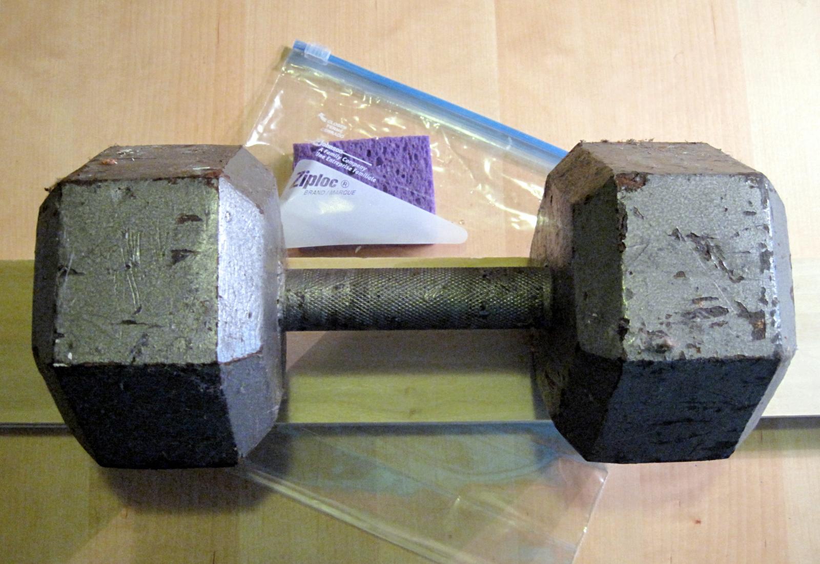
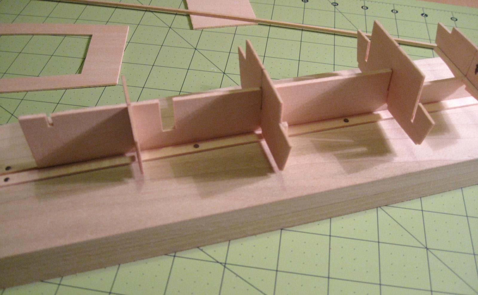
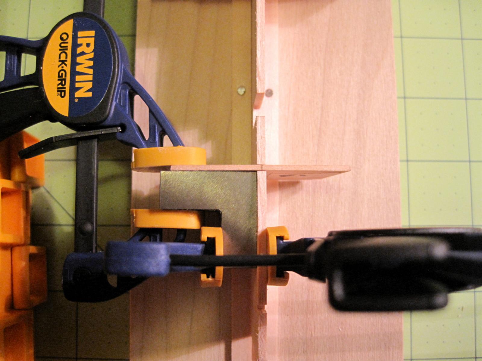
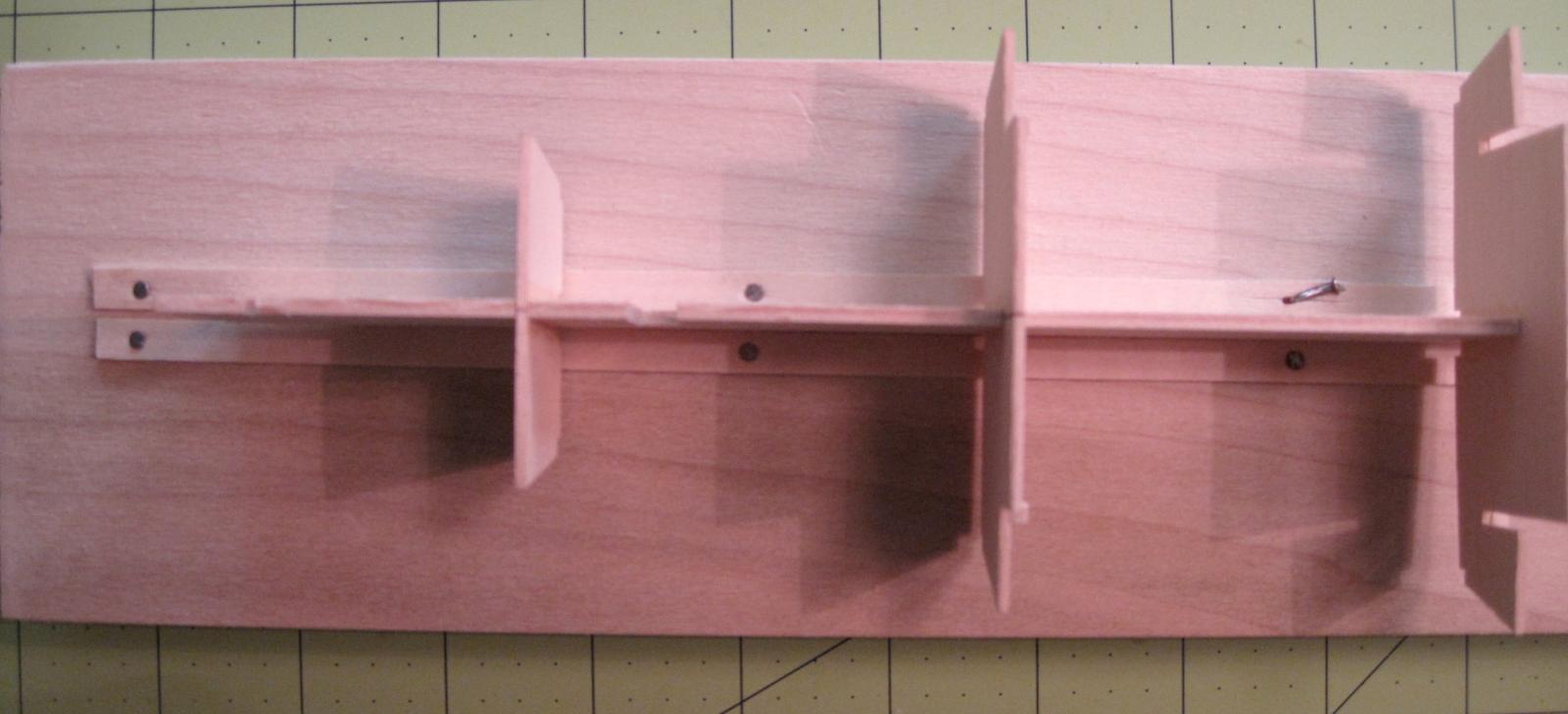
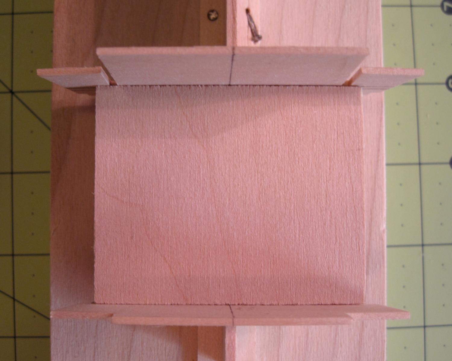
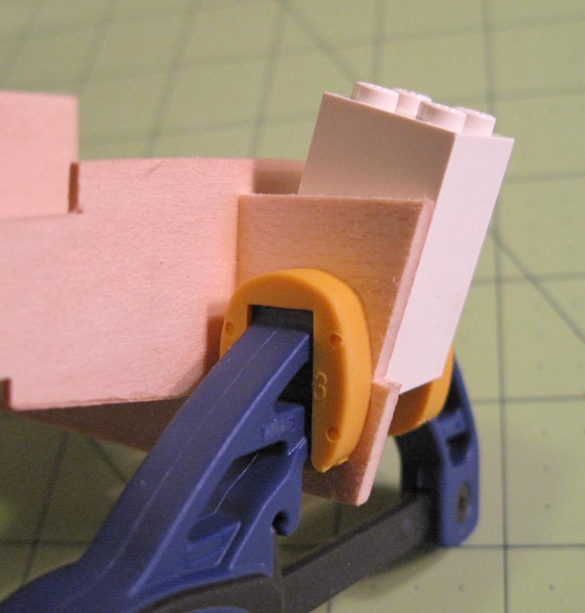
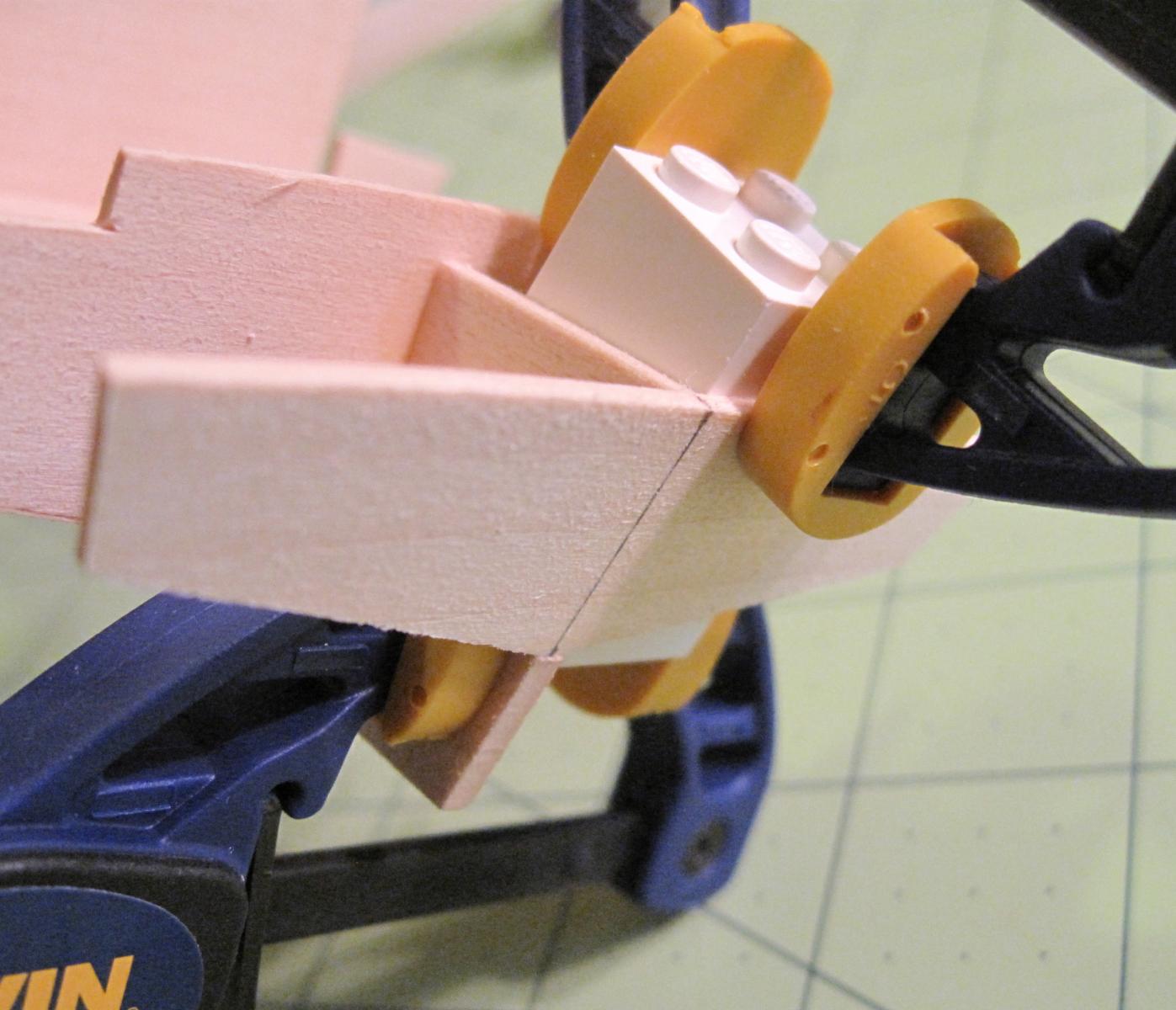
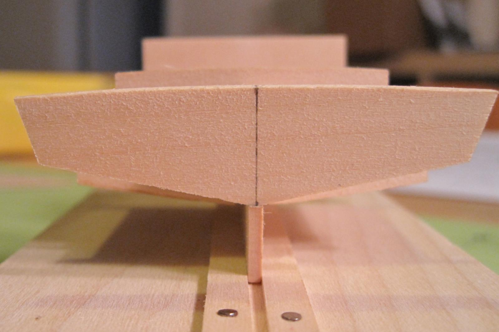
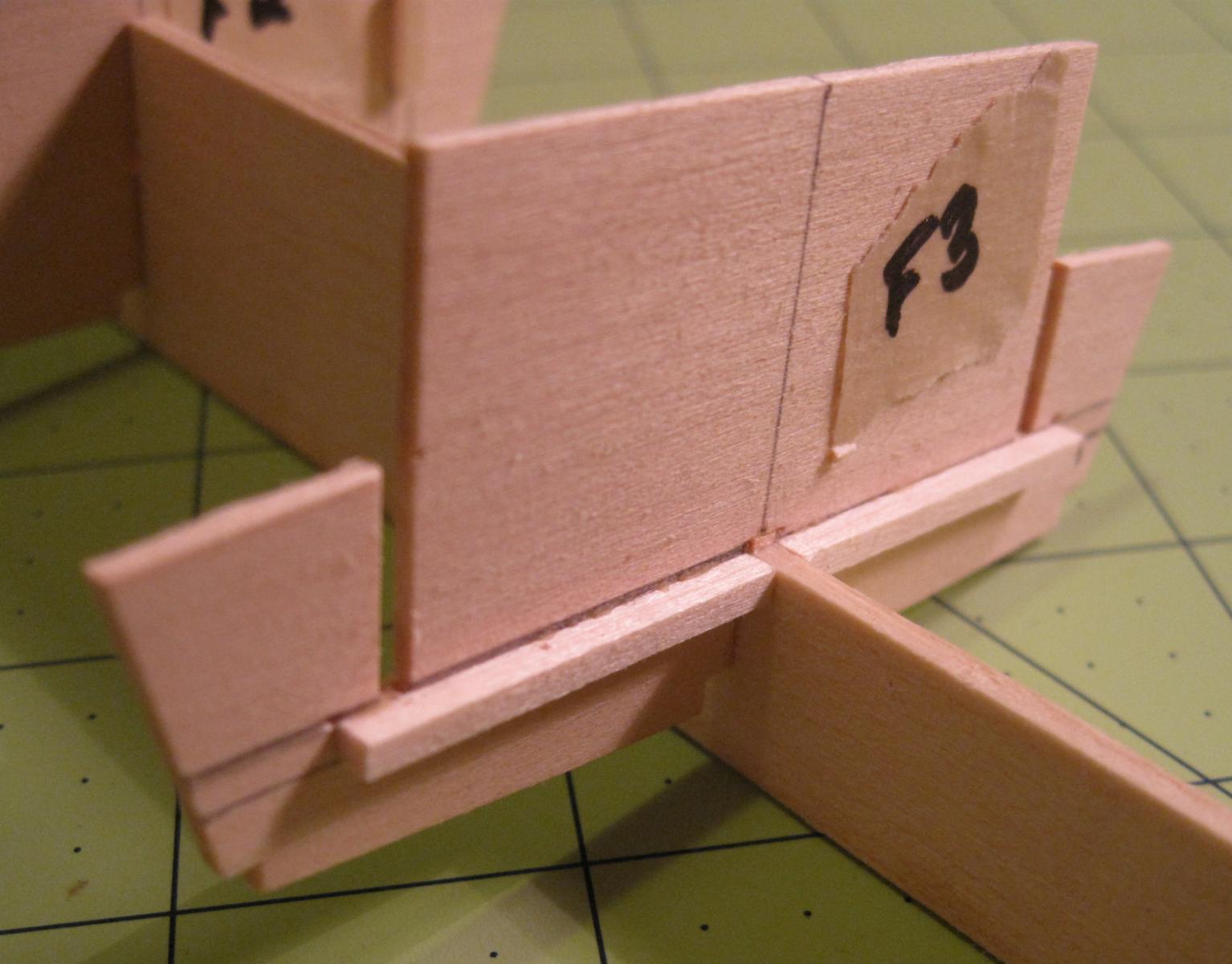
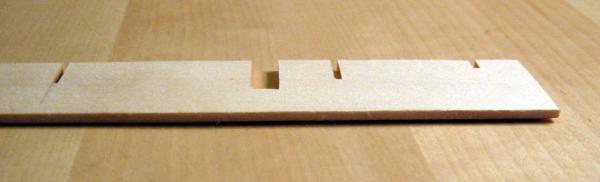
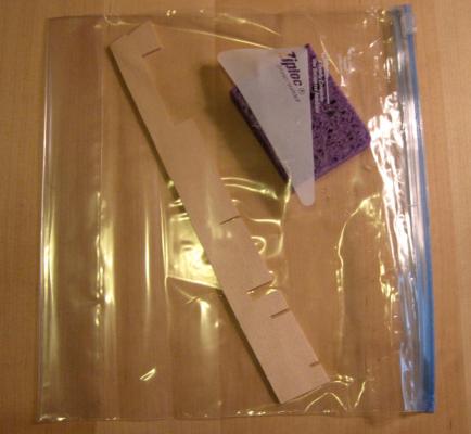
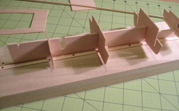
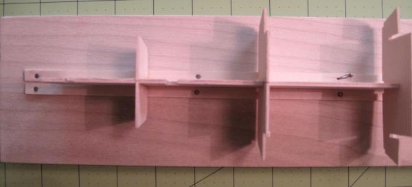
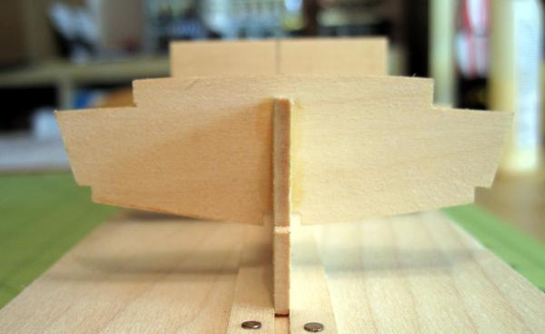
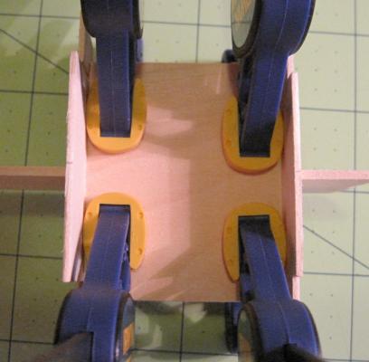
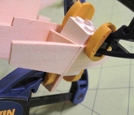
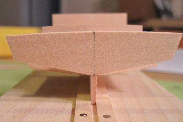
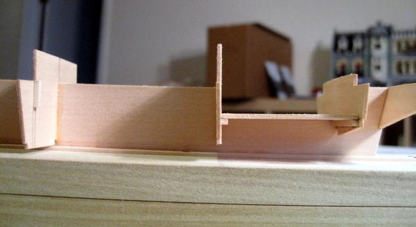
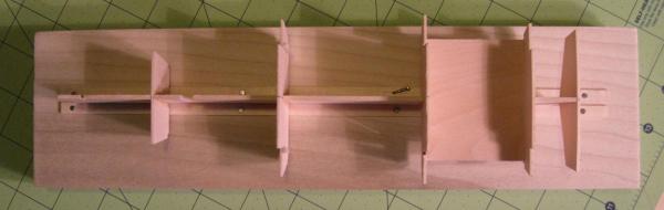
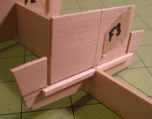
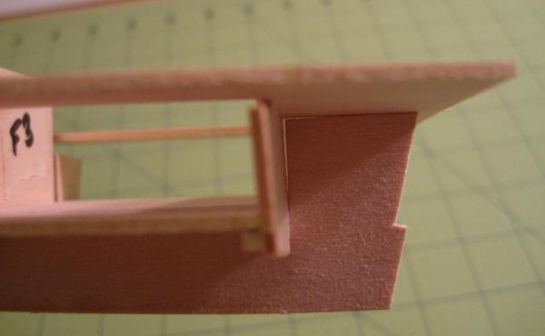
Made some progress this weekend… As I mentioned, I’m concerned that the keel is twisting just a tiny bit. In this pic, I’m lightly holding down the opposite end: Per some suggestions I found on the forums, I enclose the keel in a gallon Ziploc with a damp sponge and squash it between a couple of flat poplar boards for a few days: (In case you’re wondering, I only wish I were buff enough to handle a dumbbell like that… an ex-Navy neighbor left it behind and I appropriated it for the task.) After a few days, I remove the keel from the bag and let it dry a few more days between the weighted boards again. There’s not much of a change: It would be nice if I could get it dead straight, but I think this is as good as it’s going to get without cutting a whole new keel from plywood, and I don't really have the tools for that. There’s only so much I can ask for from 1/16” solid wood from a $25 kit. I imagine higher-end kits with their thicker plywood keels and bulkheads would do better here. In any event, I think I can eliminate the tiny twist remaining when I clamp down the deck. I also throw together a simple keel holder using one of those poplar boards and some spare basswood from the hobby shop: This could be fancier, but given the lack of real planking in the model, I don’t think I’ll need it very much after attaching the bulkheads. I just want to keep the keel straight while the glue dries. I clamp the bulkheads in place with a square angle block I got from Micromark and sparingly apply some yellow wood glue with a #2 paintbrush: After repeating that for each bulkhead over the course of an evening, I go back and apply glue to the joints that the angle block was obstructing. The results look pretty good: However, bulkhead F3 is a bit skewed relative to F2 due to the slight keel twist: Again, I’m not sure how much I can do about this without more surgery than I’m looking for in this build. I think that clamping the deck down will minimize the twist, but I’m not sure. Suggestions welcome. After taking another look at the fit of the cockpit floor, I’m not so happy with the joint or the finish of the edges, which will be quite visible in the final model: I cut another piece of basswood to size and hand sand it to fit with a sanding block. I tried using my old Delta disc sander, but it doesn’t have the precision needed to get a good square edge. Just eyeballing it turns out pretty well, a slight improvement over the original piece: Add some glue and clamp it in place after erasing and sanding off the centerlines down the cockpit bulkheads: I scrounge up a conveniently shaped Lego to help fix the transom in the correct position, add glue, and clamp it down, keeping just enough slack in the keelwise clamp to allow me to check and adjust the transom’s position: I think the results look quite nice: Cockpit floor looks good too, along with an overall shot of the skeleton: For a first attempt at precise frame-building, I’m pretty happy with this. I just wish I could completely eliminate that keel twist. It basically all happens between F2 and F3, and that area will be enclosed by the cabin. So I think I could build up some blocks to precisely fit between those bulkheads and carefully twist the keel back into alignment while clamping the ends of the blocks to the bulkheads. But I’m not sure how much it’s going to matter or how likely it is that I’ll screw something up in the process. I’ve got plenty of time to think about it, at least – work will be too busy for modeling this week and I’m off to Annapolis next weekend. So it will likely be two weeks before I touch the model again.


- 15 replies
-
- 5
-
-
- chesapeake bay flattie
- midwest products
- (and 1 more)
-
johncole reacted to a post in a topic:
Chesapeake Bay Flattie by tppytel - Midwest Products - 1:32 - SMALL - First build
-
johncole reacted to a post in a topic:
Chesapeake Bay Flattie by tppytel - Midwest Products - 1:32 - SMALL - First build
-
I wish I had that much time available, but I'm basically only going to be in town for a day and a half for my 15th year college reunion. I'll have just enough time to hit my reunion activities, take a walk around town, and visit with a former student of mine that started at the USNA this summer. In on Friday afternoon, out Sunday morning. Serious maritime research will have to wait for another visit. The build will be on hold this week as I start school (I'm a HS math teacher). The keel was a teensy bit twisted anyway, so it's getting moistened and flattened right now and I won't be ready to continue until next weekend even if I had the time.
-
ccoyle reacted to a post in a topic:
Chesapeake Bay Flattie by tppytel - Midwest Products - 1:32 - SMALL - First build
-
That's the one Dee Dee linked. It's a beautiful build, but it's clearly over my head at the moment. He's looking at the whole build and predicting how his materials and methods will contribute to the final outcome, and then adding in a bunch of custom improvements along the way. I'm just figuring out which part goes where and how to keep the whole thing square. I hope to be able to think that way at some point, but I'm not there yet and I'm OK with that. But it's certainly a great example of how you can take a small build and execute it with great expertise. Fantastic work!
-
Thanks Josh. I already ordered the book from Amazon in this case, but I'll keep abebooks in mind for the future. I buy a good number of books on various subjects and have usually found that Amazon is as good a price as anywhere else, and always more convenient. But it does look like ship modelling books might have a different economy than most - the Chapelle book is a 1 to 3 week wait at Amazon, which is hardly typical. I ordered it from a 3rd party that had it in stock for ~$35.
-
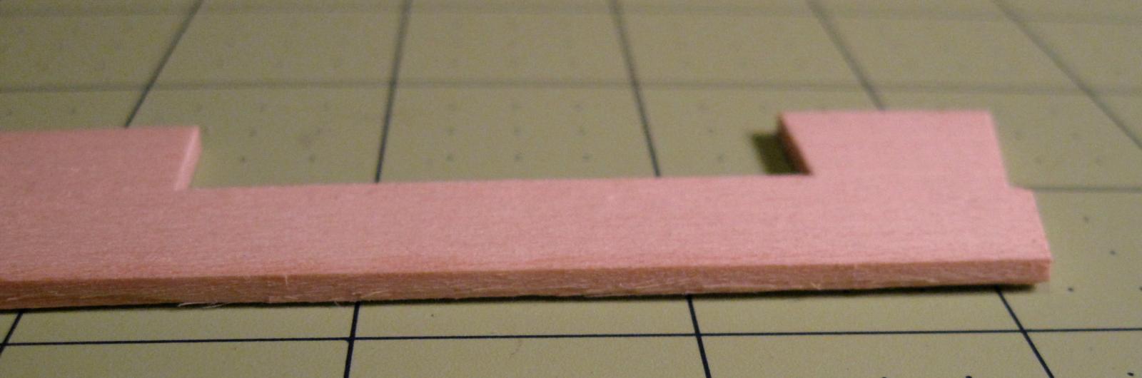
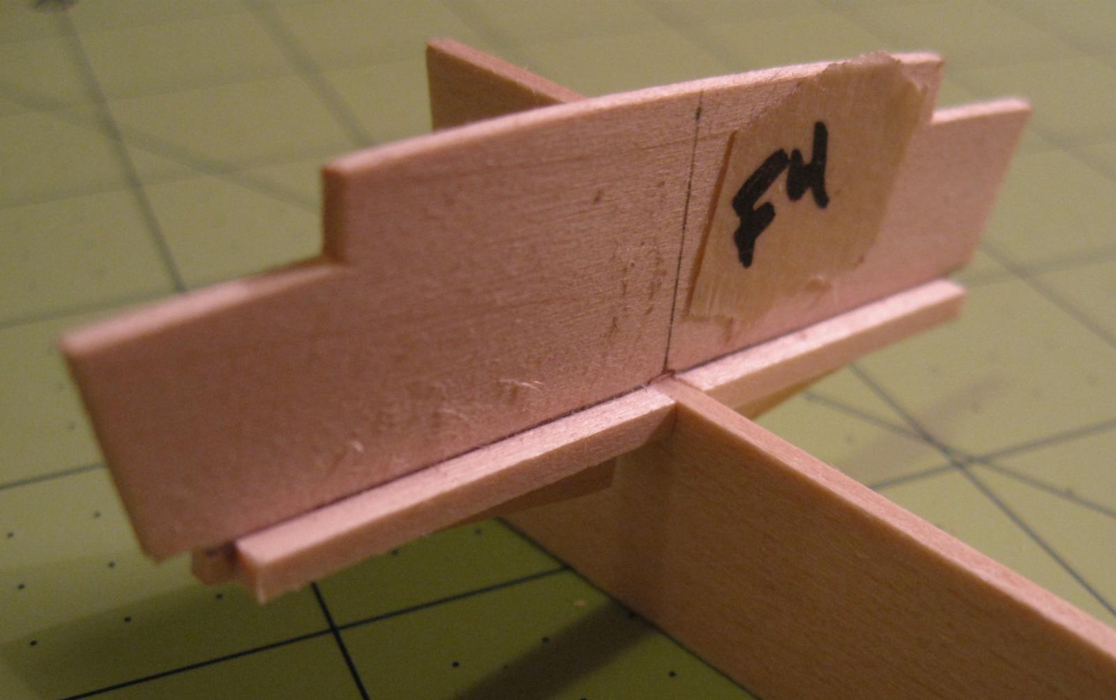
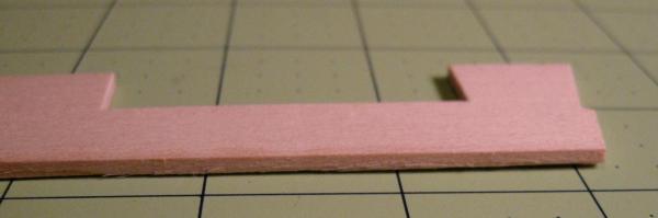
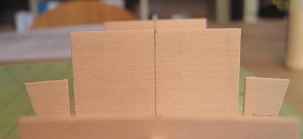
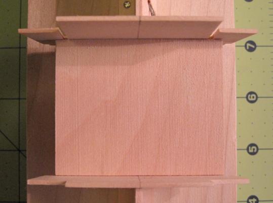
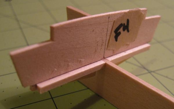
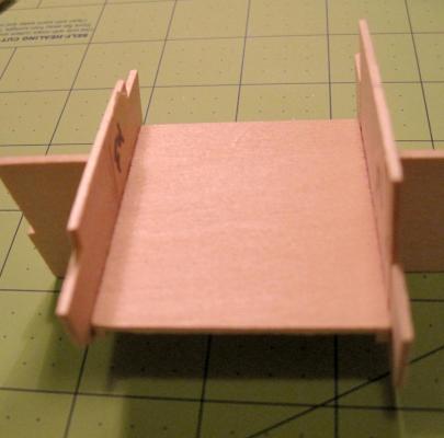
Thanks for the references Dee Dee. I've ordered the book and will check out the log. And I agree... you do feel the maritime history living in Annapolis - once you can get past all the cheesy crab merchandise, at least. For a Chicagoan like me, it was an inspiring place to live for a few years. Coincidentally, I'm going to be visiting Annapolis in just a couple of weeks. Hopefully I'll have time enough to hang out near the water a bit. The main drag around downtown is OK, but my favorite spots were some of the side streets and less-traveled spots. As for the model, I shorten the bulkhead slots with some shims and do a little more file work. The fit is much improved: I go ahead and test-fit the cockpit floor and the deck. Without the bulkhead glued in place, this is only an estimate. The floor looks OK: The floor was precut and is a tiny bit short in the top right on the pic, but I think I can live with that. This was a very inexpensive kit ($25!), so I wasn't expecting perfection going in and I don't really want to go replacing a bunch of parts unless it's absolutely necessary. The deck is a good fit side to side, but the opening is too short lengthwise and pushes the F4 bulkhead forward: I'll probably need to elongate the opening a bit, but I don't think I can do anything about it until the bulkheads are glued in place. Question: The only printed reference I've purchased so far is Mastini. He lays out several methods for ensuring perfectly square bulkheads beyond just using a square on each one individually. But it doesn't seem like any of them work here. The deck in this model is unplanked and is curved athwartships. So I can't pin through the deck (Mastini's 1st method), since any holes will be visible. And since the deck isn't planar, I can't take strips marked at the bulkhead slots in the center out to the edges (Mastini's 2nd method). I've studied the model a bit looking for some alternate method, but I'm not seeing one. Is the only choice just to square each bulkhead as closely as possible, or is there some other squaring trick I'm not seeing here?
- 15 replies
-
- 1
-
-
- chesapeake bay flattie
- midwest products
- (and 1 more)
-
Hi guys - thanks for checking in! I took another look at those last two frames and I think I glued the braces on just fine. It's just that the center slot is too deep, either because the die cut is off or because I accidentally took some wood off with the file while working on the slot width. So I added a little shim in each one and will file that back to get the braces flush to the keel. Then I should be good to move ahead with some more fitting and assembly.
-
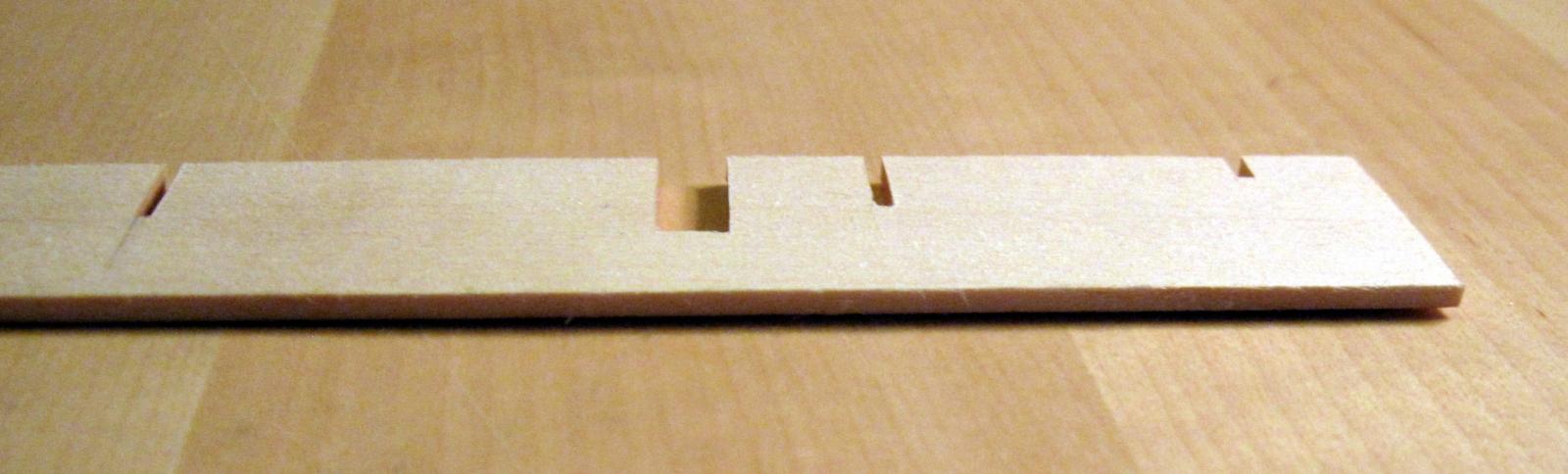
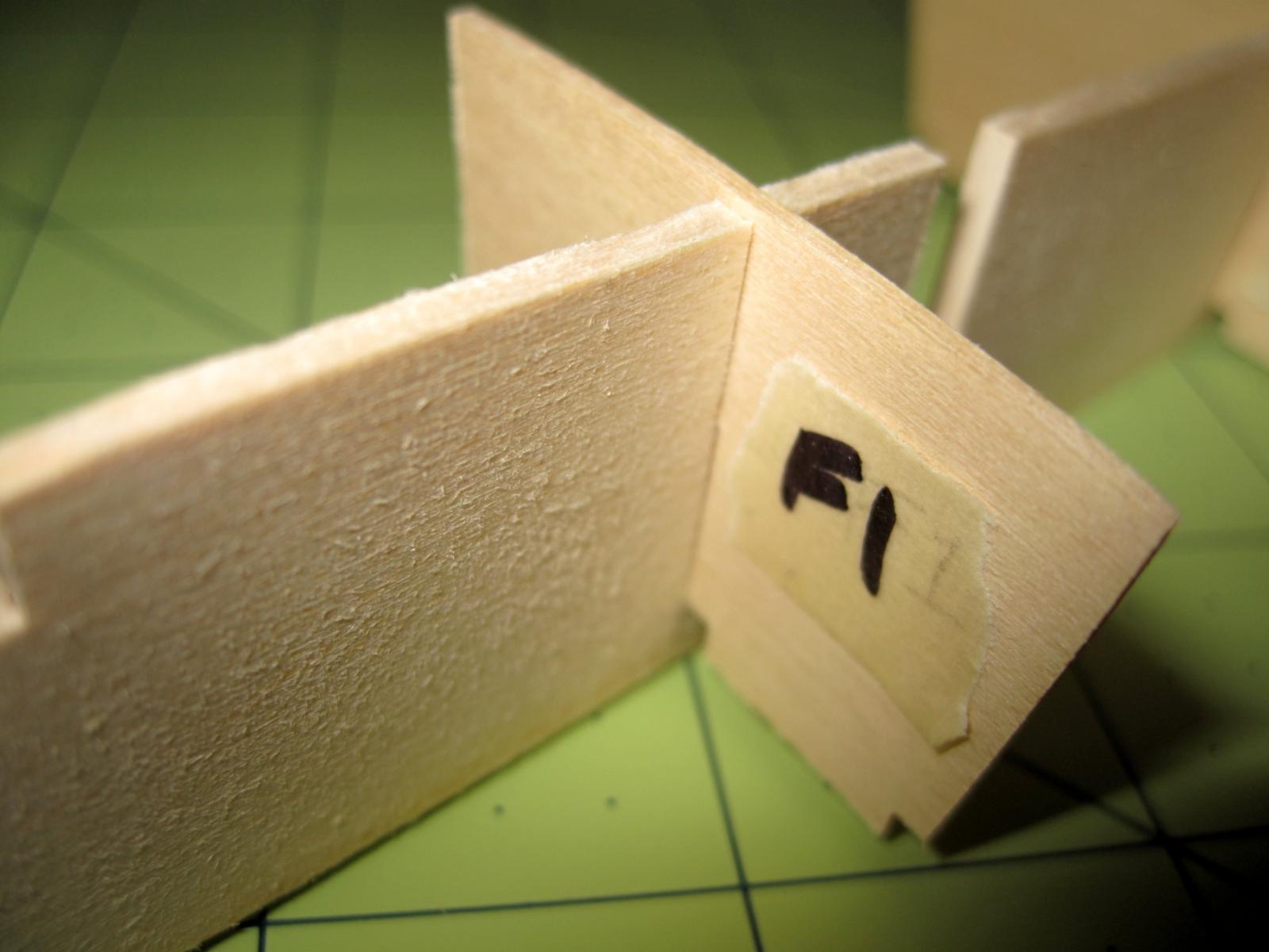
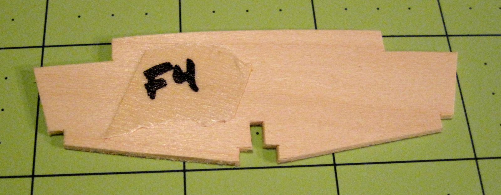
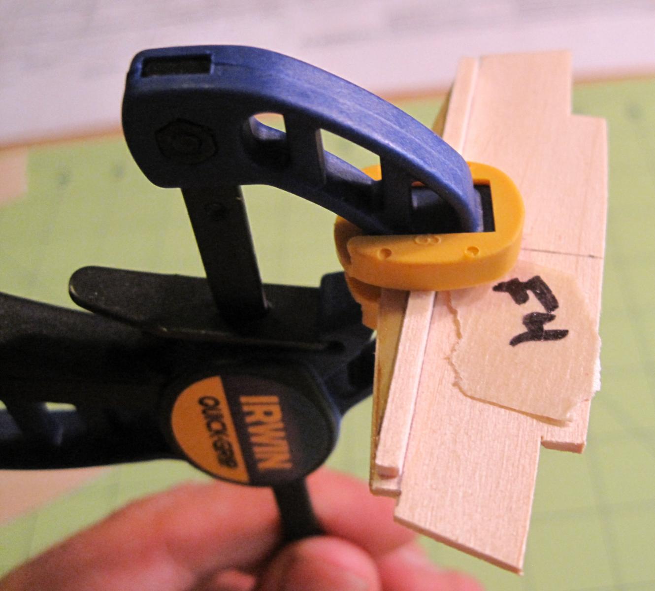
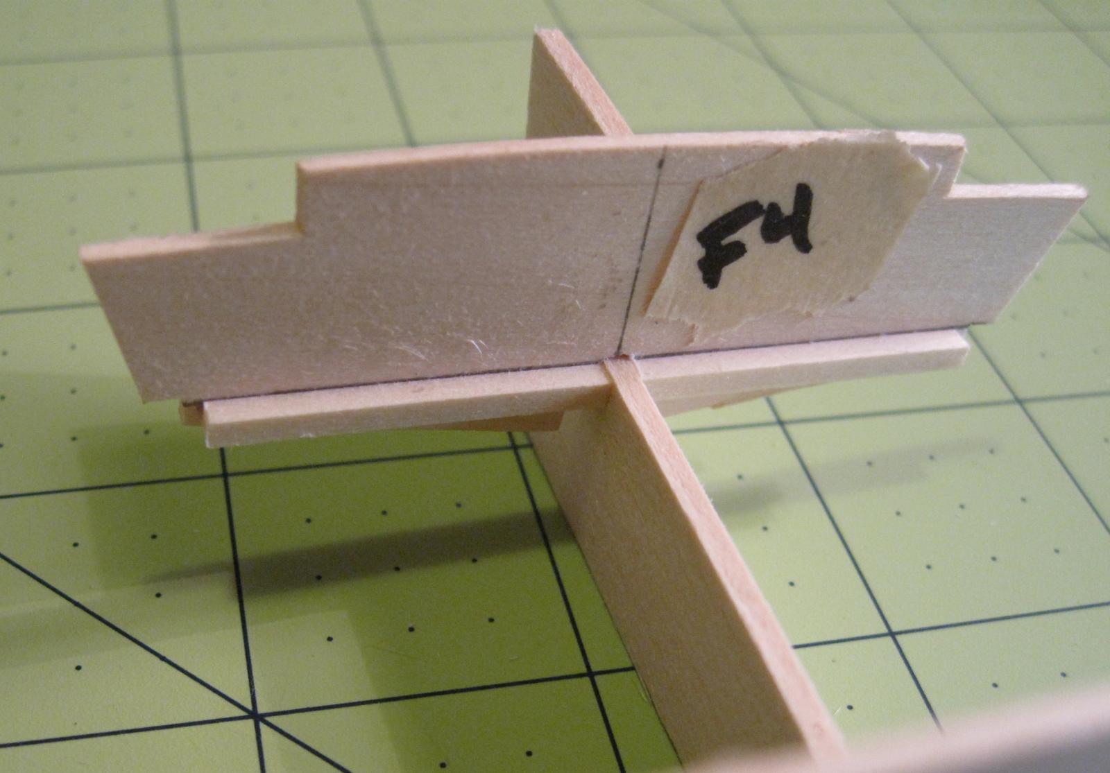
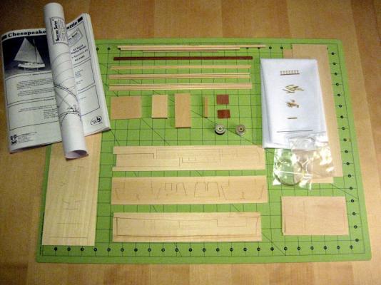
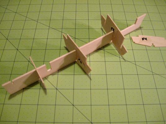
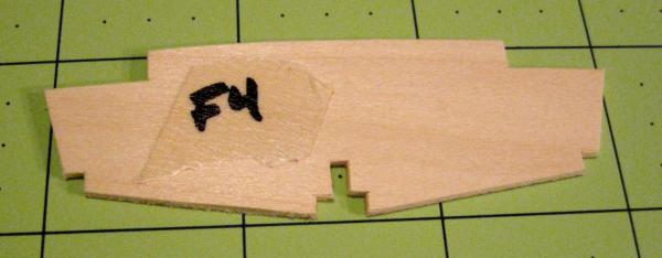
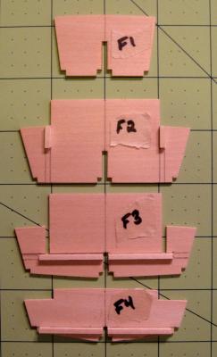
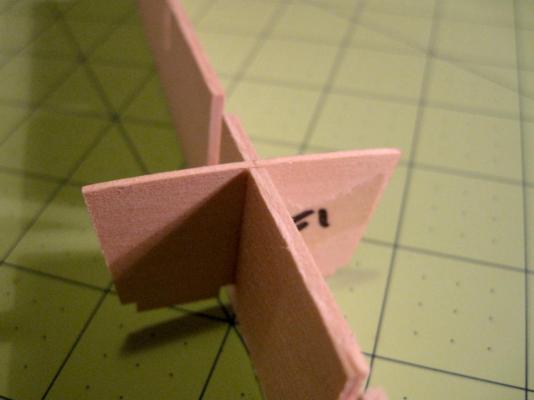
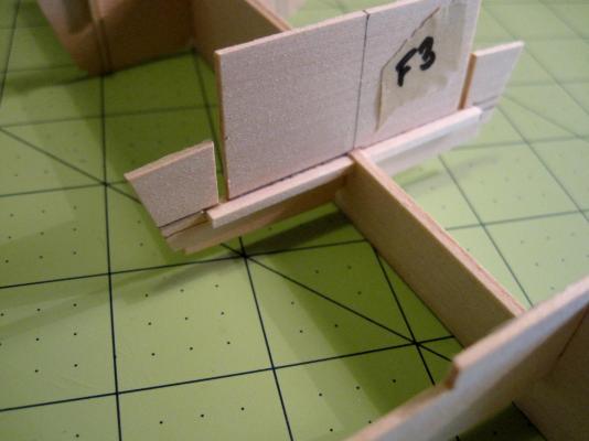
I am a complete newbie to model ship building. I've built some plastic models long ago, have painted gaming miniatures and terrain to a good standard, and have some basic carpentry and woodworking skills and tools, so blending all that together into model ship building seems approachable. For my first build, I wanted something small and simple - small so that I could be absolutely certain I'd complete it in a reasonable time, and simple so that I could concentrate on learning the basic skills well. Some web searching brought me here and also turned up a detailed tutorial on building Midwest's Flattie at themodelshipwright.com. Even though that tutorial is basically just an illustration of following the directions, it's nice to have a few extra pictures and tips. I also attended college in Annapolis (St. John's) and have spent some time on the waterways of the area, so the little Flattie speaks to me a bit. So, the Chesapeake Flattie it is! Again, a big reason for going with a small model is to focus on a doing an excellent job of the basics. So I'm especially appreciative of suggestions for improving my technique for the future. Let's get to it... here she is, fresh from Amazon: I lay the parts out for an inventory. Everything is here, and there are no obvious miscuts or damage. I read through the first few pages of instructions thoroughly at this point, and skim the rest. Nothing too surprising or intimidating here, and I'm comfortable with the flow of the build and how the various parts should fit together. Very newbie-friendly. I cut out the frames carefully, sand the edges lightly, and do a quick dry fit and inspection: Some problems show up right away. Frame F4's slot is too narrow to slide on. Frame F3's slot is too wide and allows the frame to wobble. Frame F1 rides a bit too high above the top of the keel... The quality of the die-cuts varies. Some frames are fine, but some are clearly asymmetric. F4 is the worst of the bunch - though the pic is crooked too, you can see the cuts at the bottom clearly don't match. All of these issues are resolved easily enough with a little time, either taking off extra wood with a needle file or adding a tiny shim with CA glue and filing that down. After those adjustments, the frames match the plans well and don't show any obvious asymmetries when examined against the grid on my cutting mat. (Link to a future post about Mastini's method.) I cut the square stripwood according to the plans, trace the extended lines from the plans onto the frames, glue them in place with wood glue (applied with a paintbrush), and clamp with a micro-clamp to dry: The frames prepped to go: They look pretty good. You can see a jaggie at the bottom of F4 - I didn't cut the shim to the full length of the edge because it was only the outside corner that was short. I should have just done the whole length, but I think this will be fine. F1 fits the keel correctly now: The braces on F3 and F4 are close, but not quite flush with the keel where the cabin floor will sit: The brace for F4 just needed to be glued a tiny bit higher, but I wasn't seeing clearly at the time how the brace was going to fit with the keel. The F3 brace, on the other hand, is dead flush with the side slots, but the die cuts for those slots don't quite match up with the center one. I could try to clean this up by sanding down the keel line between those frames, or by using a shim to shorten the center frame slots. Bbut I'm not sure if it's going to matter or if that could throw off the fit of any other pieces. Suggestions welcome. That's all for now. I probably won't be able to get back to building until next weekend.


- 15 replies
-
- 2
-
-
- chesapeake bay flattie
- midwest products
- (and 1 more)