craigb
-
Posts
72 -
Joined
-
Last visited
Content Type
Profiles
Forums
Gallery
Events
Everything posted by craigb
-
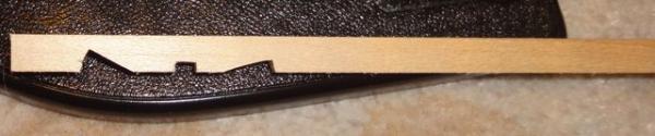
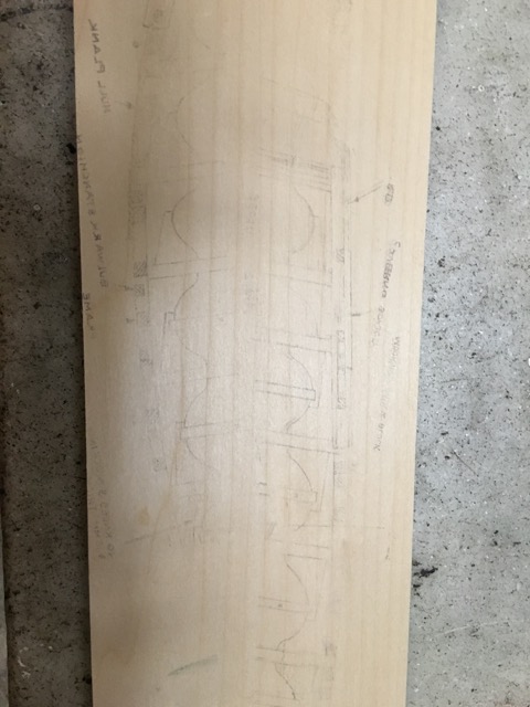
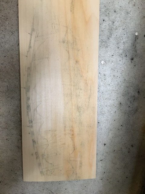
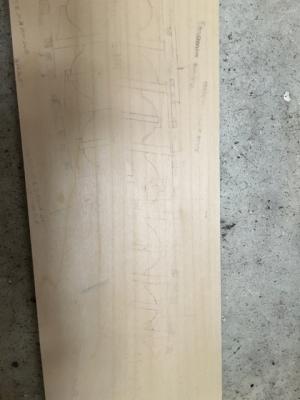
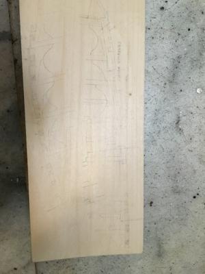
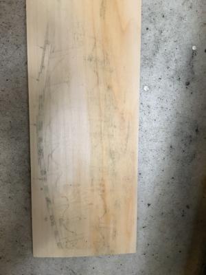
 With the interior fitted out, it is time to finish lofting the deck frames. The kit doesn’t come with the wood for that, because the pieces are a total pain to make, and will never be seen in the finished model. So I decided to make them and hide them forever. I went on down to the crafts store and got a piece of 1/8” basswood for all of $3. I love living in NYC where I can walk to places like this. The place caters to the art college across the street and is very well equipped with many sizes of wood as well as pretty much any craft supply you could think of. Lots of fountain pen stuff too, oddly, but that is a topic for another time. The knees are interesting pieces. I read somewhere that you can transfer laser printed sheets to wood by ironing them. So I scanned in the plans and printed them out on the laser printer. Then turned the iron on and went to town. Results were ok… sort of. The lines were pretty faint, a bit inconsistent but pretty crisp. I think being really aggressive with the heat (and no steam) would be best. I’ll do that next time. At “home” I have a dedicated iron for putting mylar on airplane wings. That would have been the perfect tool for this, as I wouldn’t have to worry about messing up the one I use for shirts in the morning. Then I remembered somewhere that you can use solvent (paint thinner etc.) to transfer it to wood, and thought that was worth a try. So on the other side of my piece of bass, I took my printed sheets and rubbed them with lacquer thinner. I did this out in the hallway of the building and stunk the entire place up. The results were very poor, soaked thinner into the wood to the point that I don’t want to work with it anymore. Specifically, the lines were poorly transferred and very blurry. Lessons learned: Heat transfer method is definitely best. Guess I need to take a walk and pay another $3 for some more wood now. Also, I cut out and sanded all the laser marks off some more deck beams. I’m still waffling on painting the interior, after all the work I did. But, one other builder (I forget, sorry!) said it is a working boat. It should be painted as such. Happy building --cb
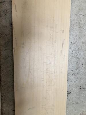
-
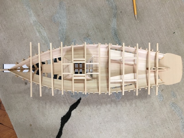
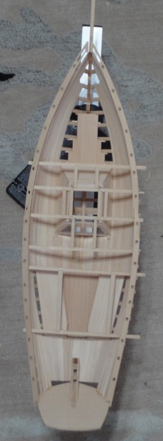
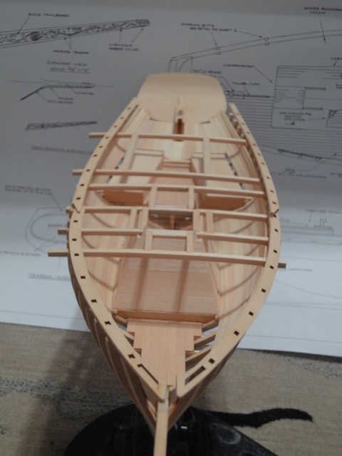
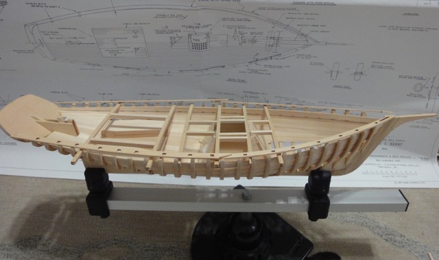
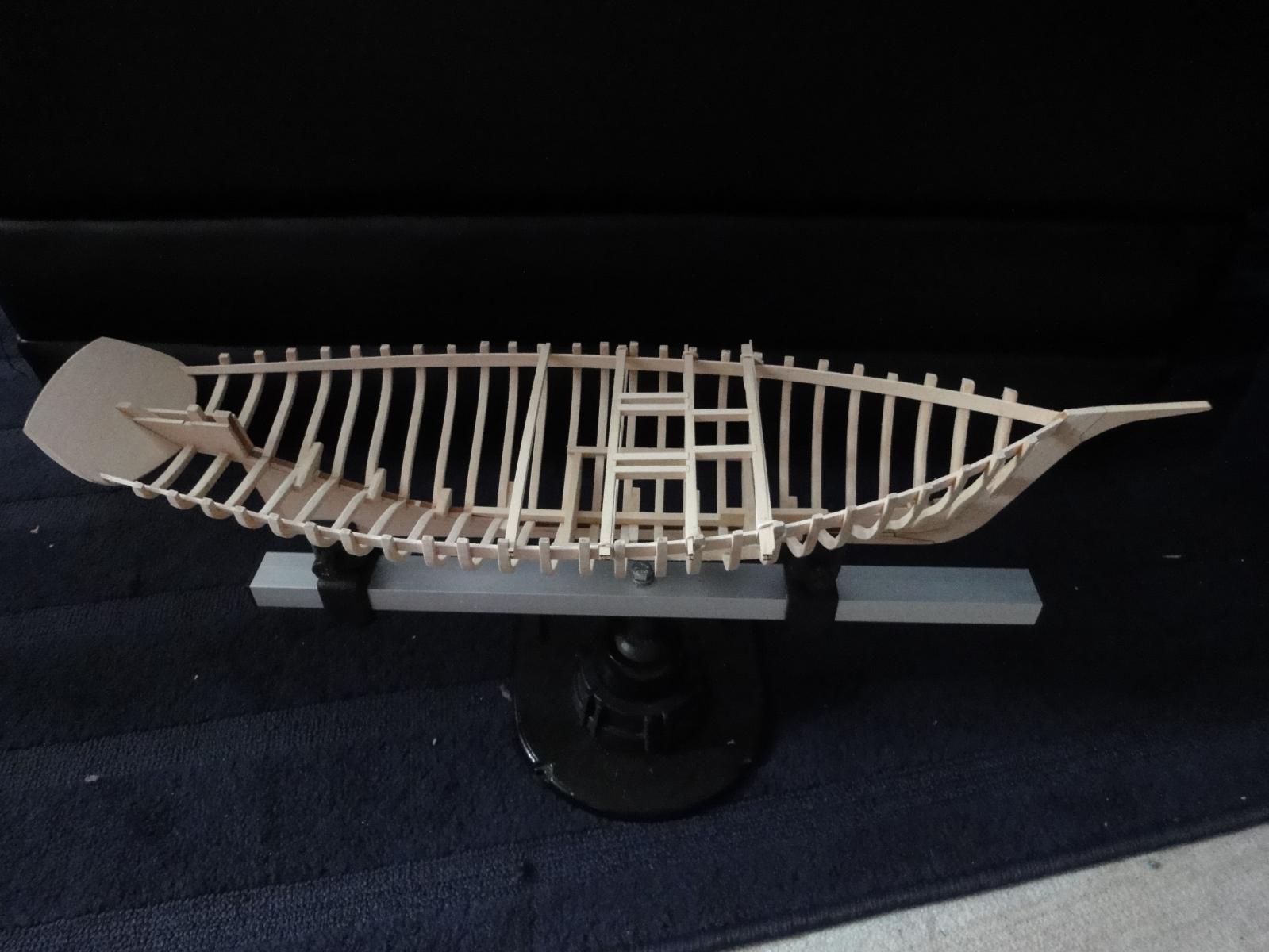
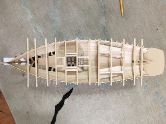
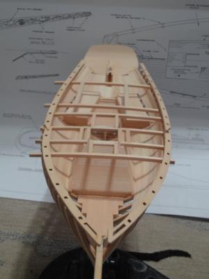
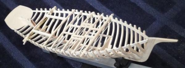
Finished fitting out the interior. Milestone accomplished. Lots of practice planking the ceilings. Next is to paint the interior, finish the deck beams, put on the covering board and build up the gunwale. Then plank the hull! Happy Building!

-
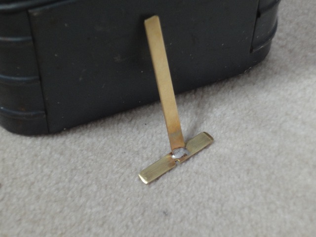
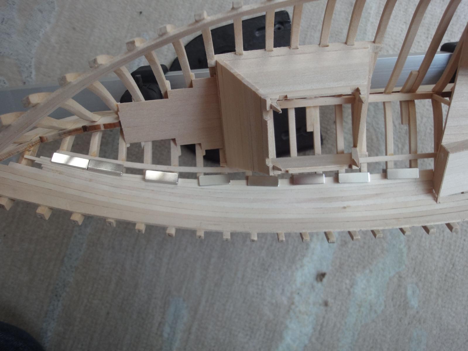
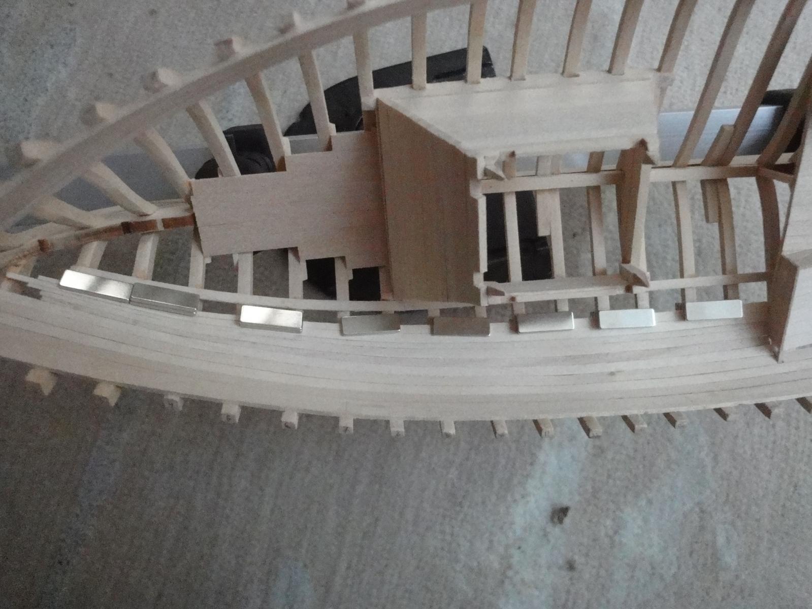
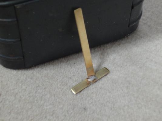
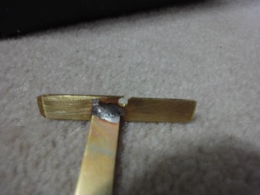
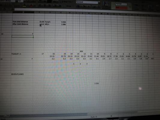
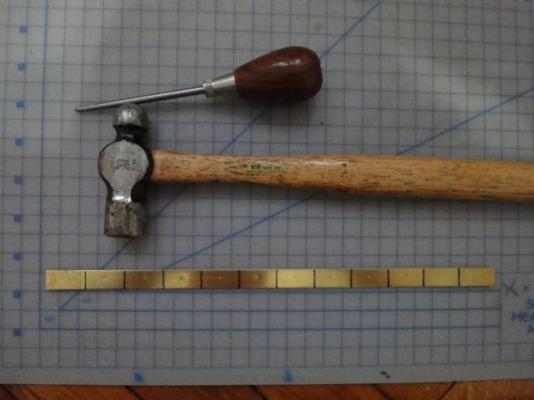
A couple of days off and rainy outside so a good time to work on the Emma. With the ceilings lofted on the larboard side, I turned my attention to the starboard side. But that seemed boring so I first took a few minutes to cobble together a teeny-tiny rabbit plane for the next step: cutting the rabbit and bearding line along the keel. I used a couple of pieces of brass strip, drilled a hole very close to the edge then opened it up with a file, creating a tiny edge. Then soldered on a handle, and good to go. Not totally beautiful, but works enough for 2 bearding lines. I hope. A couple of test passes on the now broken jig used to loft the frames, and all looks good. Then, I planked in some ceilings along the larboard side, just aft of the wet well. All the strips were the same width, so I didn’t have to spend a lot of time getting them all tapered. This left a little gap, so I took a couple of wider strips, and tapered those nearest the centerline. Then glued it all up in one go. Amazing how some things take forever and look easy and other stuff takes no time and gets results. Case in point, I finally started measuring, calculating, and sanding the tapered ceilings for the starboard side. I took the caliper, measured the gap and used an Excel spread sheet to calculate the width at all the frames. Then used the same caliper, set to those dimensions, to scribe lines on the ceiling plank and sanded to width. Once that was done I used a combination of my home made brass clams and neodyneum magnets to hold the plank in place for gluing. I’d estimate each plank was about an hour. Tomorrow I hope to finish up the starboard ceilings, and thus be done with most of the interior details I intend to model.


-
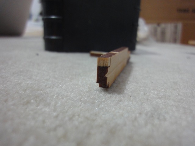
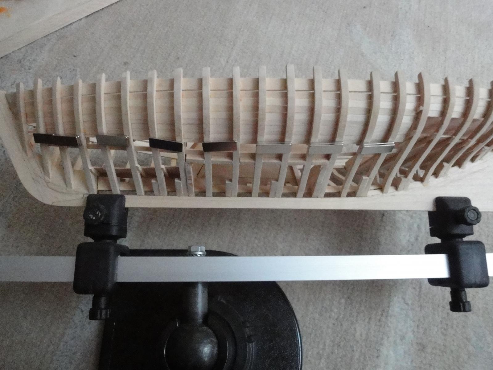
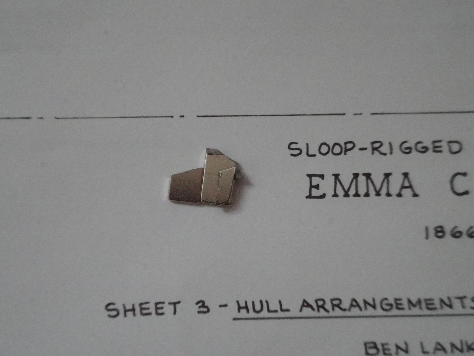
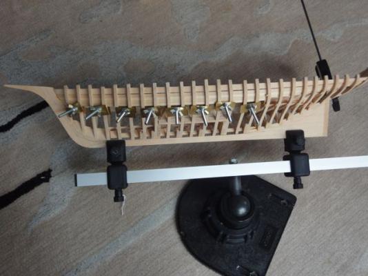
Just popped out for a gallon of milk and… holy cow! That was 2 ages ago! Work continues on the Emma. My plan to use neodymium magnets as holding devices for planking worked pretty well. Sure, the home made clamps worked a bit better because you can custom set the tension, but I think the magnets will be the way to go for holding the outer planking when the time comes. If the force isn’t good enough for you, you can always double up the magnets- that seemed to work well and you can see it a bit in the photos. I will also add a couple of warnings: 1) These are strong! Keep all your other metal stuff away or you may find the magnets flying across the desktop and grabbing stuff. 2) If one does go flying, they are really brittle and break pretty easily on impact. This has already happened (see photo) And, with that, the ceilings on the larboard side are done. The last one had to be custom sanded with a lot of trial and error, but it finally fit and looks nice. A quick sanding, and it is on to the starboard side. Getting the sides to match will be fun… Finally, at some point along the way I held it up to the light to see how tight the planking was. I won't be doing that again. Happy building.


-
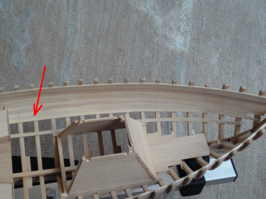
Michael: I sort of like the floor for working because it is just a big flat space after all. But my back does get tired after a while. Someday I will have a real workbench. Eamonn: Thanks for the kind words! I too get ancy when builds I’m following go stale for a while. Hamilton: I checked out your build log for the Glad Tidings and what a wonderful model! It is an inspiration for this Emma build. Good to see another non-warship. The rig looks pretty similar to Emma so I will definitely refer to your build when it comes time to rig. I also browsed the Blandford build and will get back to it in detail tonight if I get a few free minutes. It is amazing how much progress you make on your models in a short time. My Phantom took 6 months, rushing. A warship in about a year is crazy fast! **-------------------** Pretty similar progress to last time. I finished test-planking the stern over on the larboard side. That went OK. Looks nice. The blueprints say the ceilings don't extend this far back, but again, I'm doing it for practice. I also tapered a few more interior ceiling planks. I tried to get all scientific about it. The accepted method of planking seems to be measuring the frame with a slip of paper, dividing the distance and making up a “tic strip.” I will do that for the outside because 1) it is what everyone does and probably works well and 2) the way I did this didn’t work too well. I made an excel spreadsheet to do the math for me, thinking this was easier. Then I scribed the width right on the plank, sanded to the mark and glued it up. What ended up happening though was that I didn’t check the width very well after sanding to the mark (live and learn) so the planks were wider than needed and some significant “creep” started happening. I tested the remaining width and it was just right for a bit less than 5 planks as predicted. No problem right? So then I started actually measuring the taper of the plank with a digital caliper before gluing up. Of course, I over-corrected somehow, resulting in a plank that is noticeably skinnier than all its neighbors. It is kinda hard to see so I made a big red arrow. This was actually waaay too skinny and now the remaining width is just a shade wider than needed, and I will probably have to use a slightly wider plank as the last one to make up for it. Ha! Live and learn. I remind myself the whole point of test planking the interior is precisely because it won’t be seen. And I’m learning a lot! I’m now waiting for my magnets to arrive in the mail. I plan on using them to hold the planks while the glue dries. My homemade clamps won’t fit any more, and this is a good stopping point. I am also thinking of good ways to sand the exterior hull planks to shape in an efficient manner. Maybe making a master plank of brass as a sanding template? One that is very carefully measured to dimension then sort of clamp it to the wood plank to be formed as a guide? I seem to recall seeing this on the forum here some time before. I will also DEFINITELY do the tic-strip method too, that way any creep will be immediately noticed and corrected early on. Finally I will line out the hull with temporary battens and some extra narrow architectural tape to maintain a nice true planking run. Happy building!


-
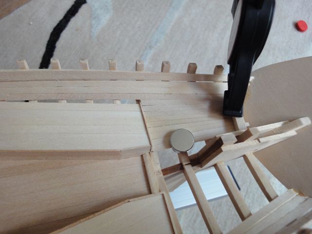
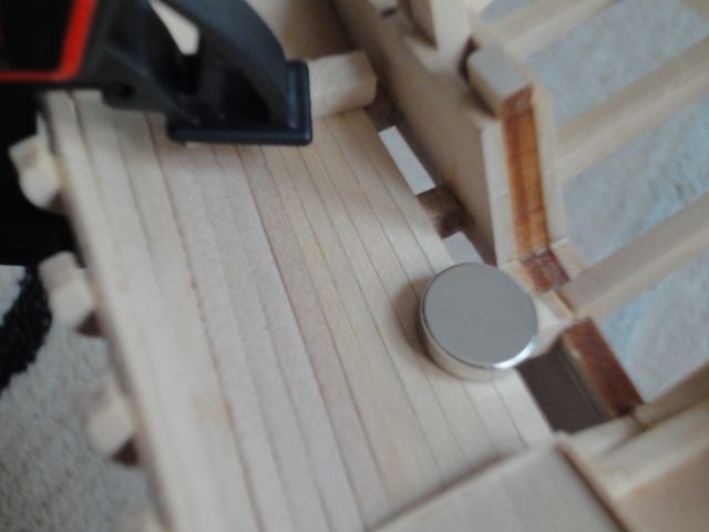
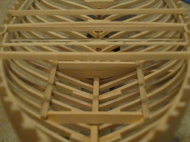
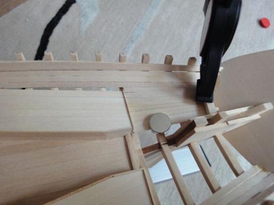
Bob: I guess MSW did some server changes or something and the photos were deleted. I re-uploaded them, and I think the build log is complete again. After the Monster Crash I have been very careful to back up everything! Nils: I plan on doing a lift-off section to allow viewing the interior of the boat. I think I will make the rear deckhouse just pop right off, but I haven’t figured out the specifics yet. I do like the diorama style showing the boat mid-repair, but several others have done that way better than I could, so I want to try something novel. That said, I do sort of like the idea of fully fitting out the interior then sealing it off forever. I recall at least one of the models in the US Naval Academy collection was of a large-ish man of war. They took a surgical flexible endoscope and found out the entire interior was fitted out, and there was absolutely no way to know that. And, thanks yet again to everyone following my build! Your words of encouragement are very much appreciated! **----------------------** With yet another life hurdle out of the way, and working a pretty light night shift, I have some day light work hours to put toward model ship work. I continued with mounting ceilings, the third on each side below the topmost “clamp.” I also took the opportunity to try my hand at some practice hull-planking in the aftermost section, aft of the bunks. I figured I could warm up and practice tapering planks to fit in an area that will probably never be seen again once the decking is in place. I carefully measured the distance to be covered, divided by the number of planks, and went about marking the width with a digital caliper and laboriously sanding the taper. The run was pretty flat, and the planks sat in nicely without much (sometimes no) need for actually clamping in place as the glue dried. Once in a while though, some creative clamping had to occur. The silver disc is a neodymium magnet with a matching one on the other side. These things are shocking strong! This was an AWESOME way to hold planks. Better than my cute brass clamps even which makes me both happy and sad. In fact, it worked so well I ordered 50 rectangular magnets from amazingmagnets.com (no financial interest in that company!) to use when I do the hull planking. Here is a close-up of the planking. It looks pretty good, if I do say so myself. It is funny, I worked from outboard to inboard, and the joints got better and better as I went. They aren’t “bad” outboard, but definitely tighter and neater inboard. I also hung another ceiling on the larboard side. I trimmed the aft ends of the finished ceilings flush with a frame using a new, sharp #11 blade going slow. Very classy! I’m pretty encouraged that hull planking will go well and I’m really glad I did this little test. The next challenge will be to match the opposite side in both number of planks used and getting the spacing to match. Finally, I test-fitted another interior ceiling along the wet-well. This is a dry-fit, and I fiddled with it quite a bit to get the compromise right between “looking good” and “avoiding as much edge-bending as possible.” I plan on using the same “measure and divide, sand to taper” method to fill in the gap. Yet more practice tapering planks before committing to the exterior hull planking. Until next time, thanks for reading and happy building!


-
As usual, excellent work and at a fast pace. Good work! I'm somewhat dreading putting in the ceilings, but you give me faith! Also, I didn't realize there was a bulkhead at frame 17... guess I need to check the plans again. I really like the weathered look. One of the old MSW 1.0 ECB builds was a wonderfully detailed diorama of Emma undergoing repairs on the shipways... your build reminds me of that one. can't wait to see it all fitted out with details. Also, it seems some of your older photos got lost... any chance you still have them? I need to fix my log too... a couple of posts worth of photos got dumped but fortunately I learned from last time and have them all backed up here on my hard drive (and the backup hard drive!) Cheers!
-
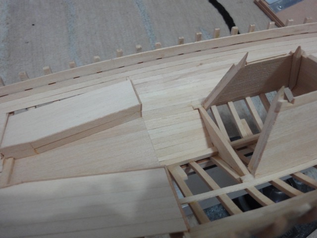
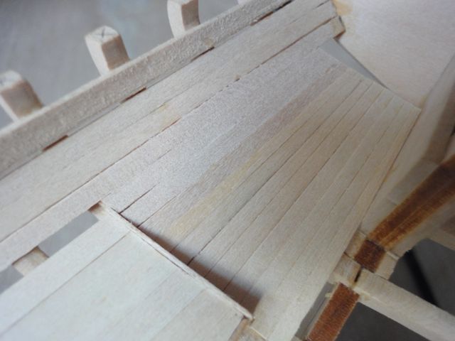
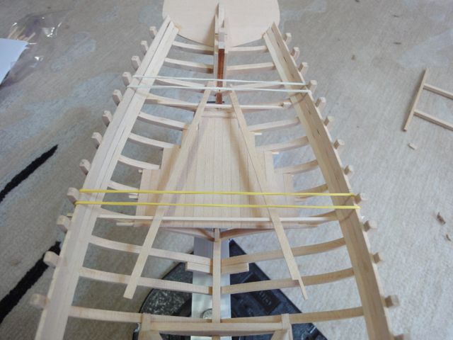
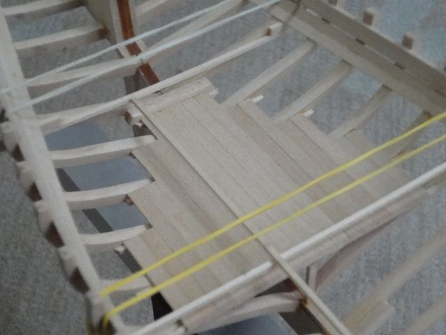
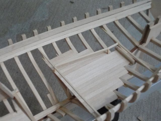
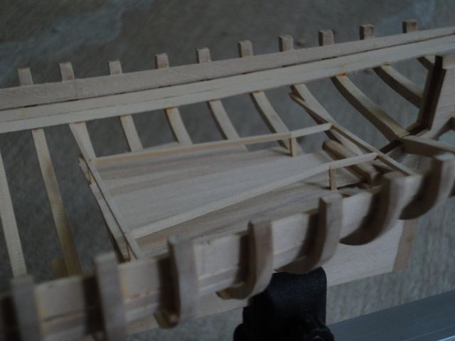
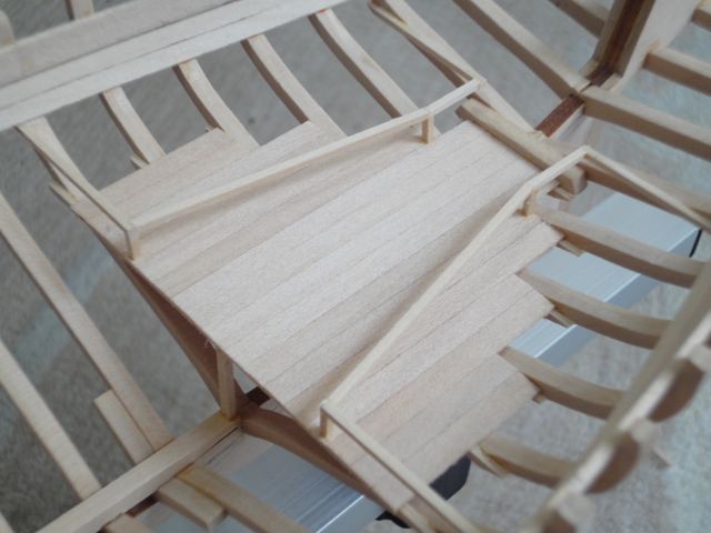
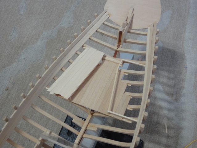
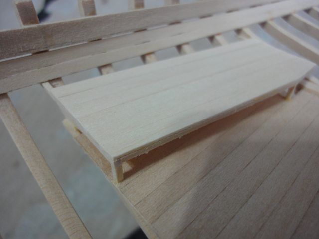
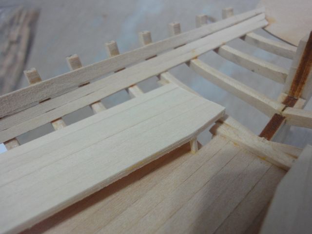
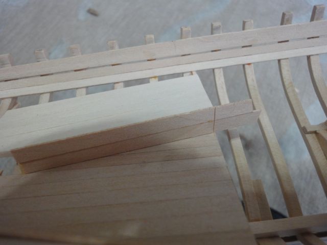
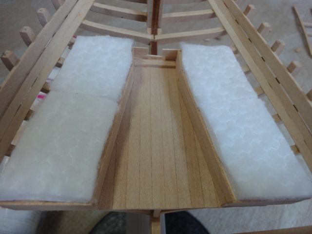
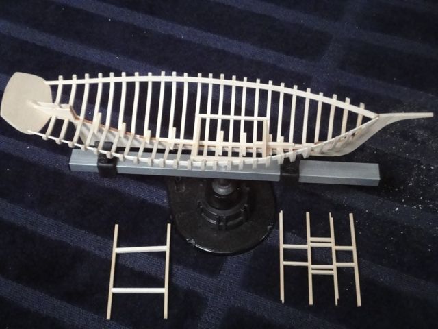
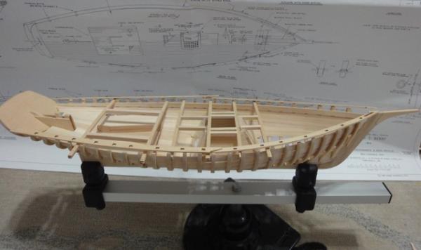
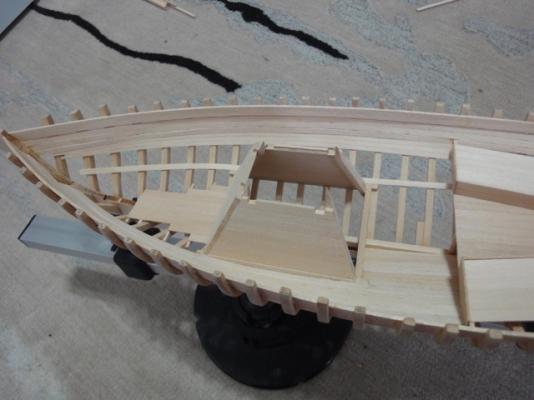
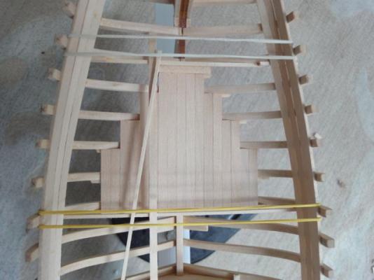
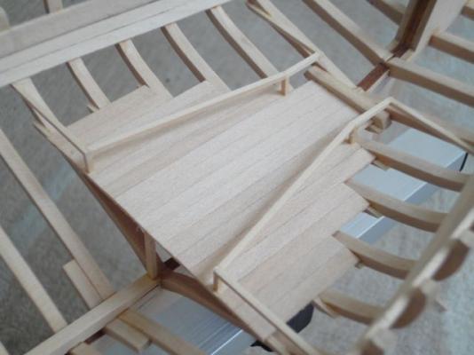
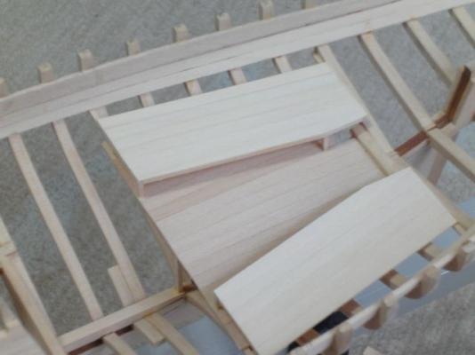
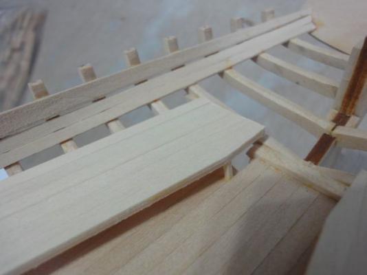
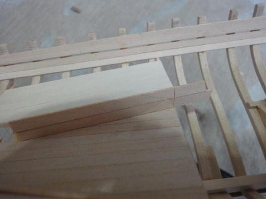
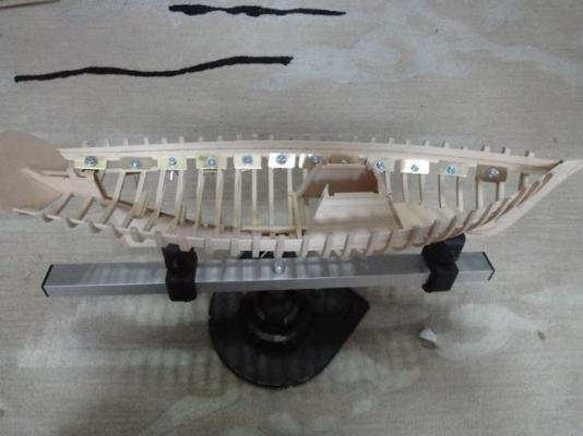
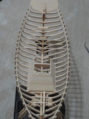
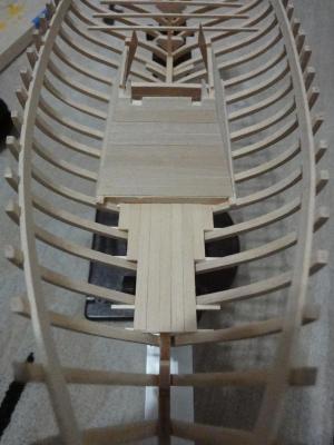
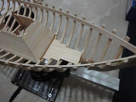
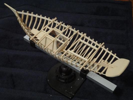
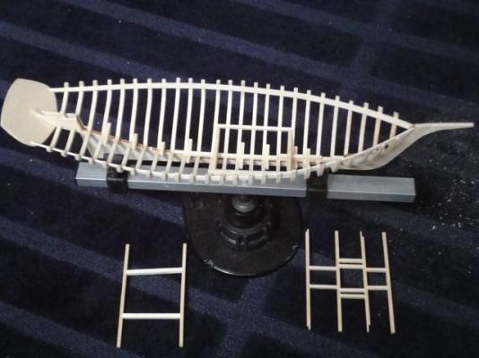
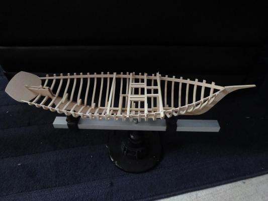
With the latest round of exams out of the way and a full weekend without chores, it was time again to return to the model shipyard with the goal of finishing off the bunks. I laid the floor beams and then planked the floor area of the rear bunk house. With some rubber bands and “test sticks” I fiddled with the layout until it looked about right. The bunks are not a straight line, and the aftermost part of the bunk has a weird little dip in, so I tried just laying some sticks out to get an idea of how that would look as well. I will also mention that the height of the bunks was set up such that two plank-widths on the edges would provide a nice little lip around the bunk. The fore and after ends of the bunk beams were done in one shot, with the goal of being to saw out the middle part after everything was built up. This would add rigidity when cutting and sawing on it, as well as assure the larboard and starboard bunks were aligned with each other. Then the weird dip-section was end-glued. It was cut short, a tiny support post fitted in place at the joint, then the length of the bunk beam siderail was fitted and glued in place. You can see little posts holding the whole thing up. There should be a little support post at every rib, and also support beams for the bunk planking, but that stuff will all be covered up, and without some serious destruction, would never be visible on the finished model. Thus, I elected to omit. Here is a shot of the completed bunk framing, sans extra bunk beams and support posts. The middle section of the end beams was then sawed out. This building method was definitely beneficial; I highly recommend it. I admit I got the idea from Chuck’s modeling of full plank-on-frame longboats and such where all the ribs have a beam that later gets broken out. I then dry-fit the bunk planking, and settled on leaving a small gap on the outboard edge. In real life, this would provide a nice place to drop your keys into the bilge. Real boats are full of this kind of stuff . Someone remind me to model a small keyring in the bilge. All the planking was glued in. I usually use just a tiny dot of glue on the ends, and nothing on the butt-edges of the neighboring plank. This provides a very clean “joint” between adjacent deck planks. The ends were then carefully shaved with a sharp hobby knife to the edge of the framing. Here is a closeup of the jointery. I liked how it looked just like this a lot, and in real life such a setup would allow you to shove stuff under the bunk. But I really wanted the edge lip around the bunks, so I settled on taking these photos and moving on. Here is what the aft part with the weird cut out looks like. At this point I was interrupted by a marathon in my front yard. Undeterred, I continued working on the boat but did yell out the window from time to time. Edge planking was fit up, the ends scored, cut, and shaved to final dimension. The starboard side is done, the larboard in progress. Here is a photo of the lip on the bunk I worked so hard on. The wetwell is in the background. Finally, I took some of my wife’s makeup remover cotton pads and cut them to simulate mattresses. A parting shot with all the deck beams replaced, and the model as it currently sits. Happy building! -craig


-
This picture is amazing, not only because it is a beautiful boat being hand-built, but it is... in the person's kitchen! I sense a very, very dedicated and tolerant partner lurking somewhere out of frame! cheers --cb
- 1,039 replies
-
- 1
-

-
- ballahoo
- caldercraft
- (and 2 more)
-
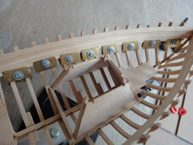
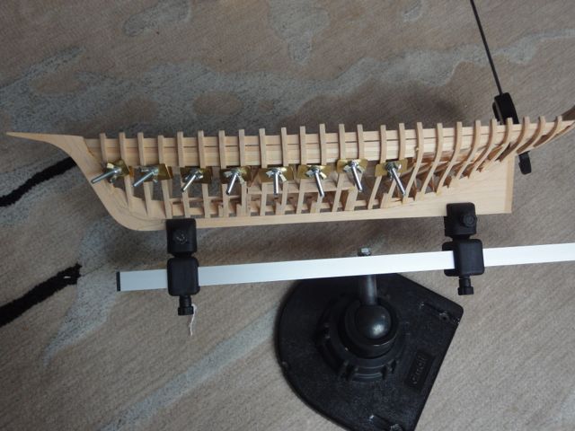
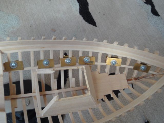
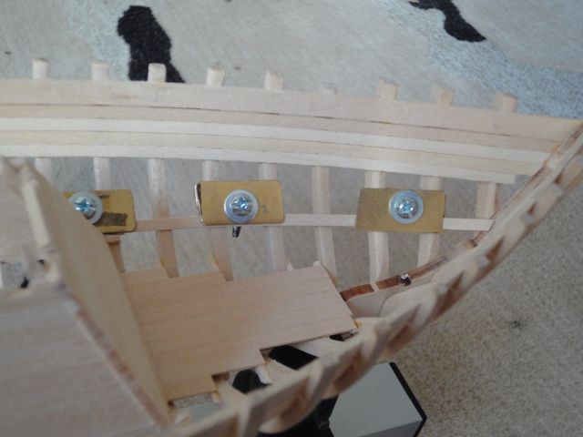
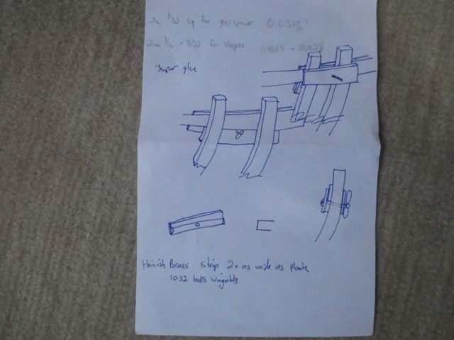
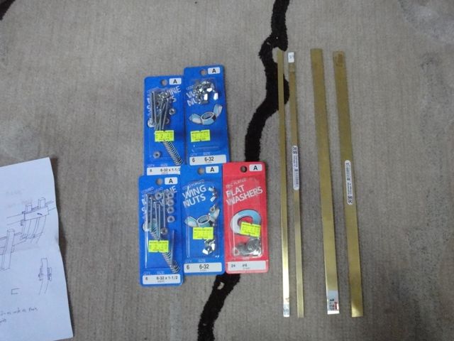
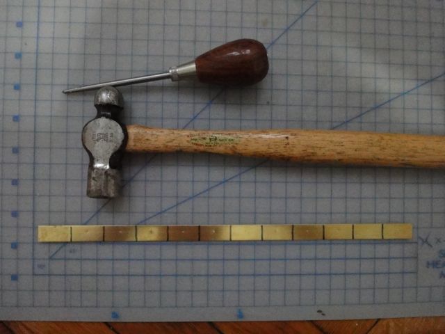
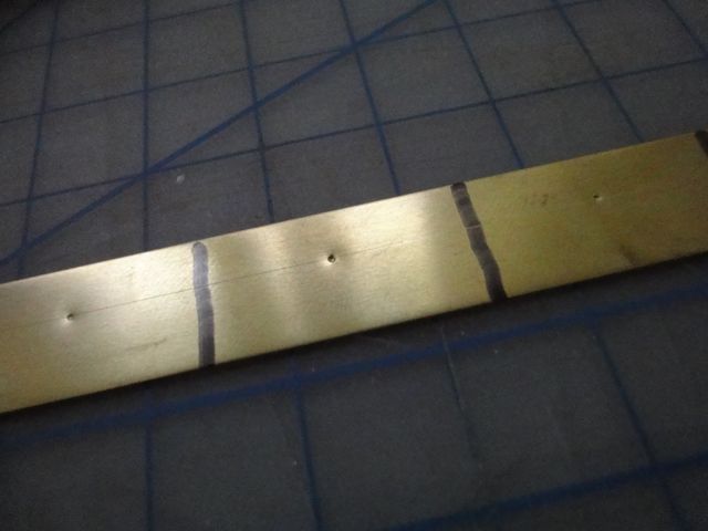
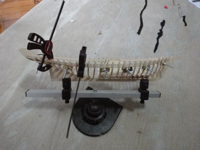
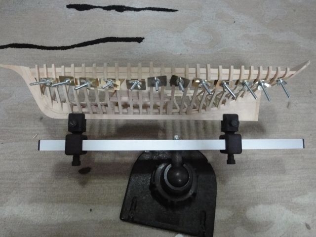
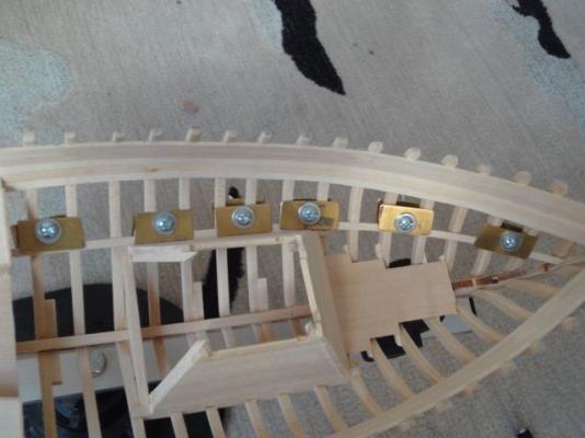
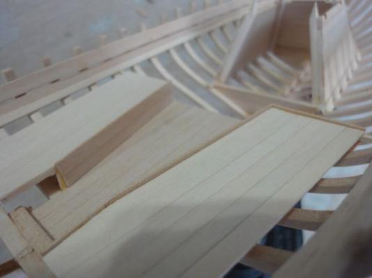
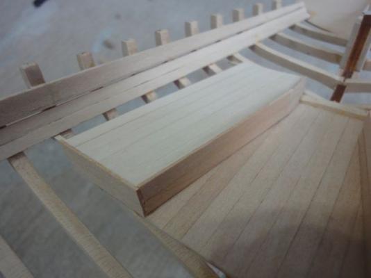
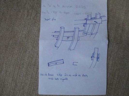
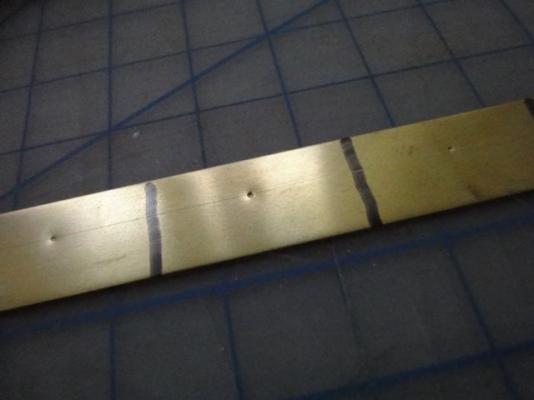
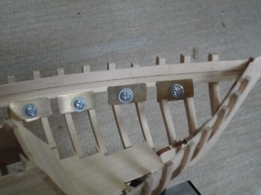
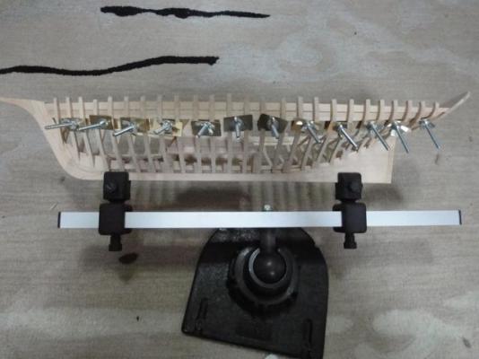
A three day weekend and the wife out of town visiting a friend means a day to work on the sailboat. I continued setting up the bunk area, but can’t figure out what height to make the bunks. To make my life easy, I decided the bunk support beams should just go under two ceiling boards. This would mean no cutting out holes in the ceilings or anything for the beams. That also meant I needed to start mounting the ceilings, which lead to a fun mini-project: Making some clamps to hold the ceilings in place. I also was going to use them to hold the hull planking in place, but a bit of thought lead to the conclusion that, with the ceilings in there, there won’t be any space to hold planks on the outside of the hull! Oh well, they are handy and kinda neat looking. And, certainly, for the next project they will come in handy. I started by making a little sketch of what I wanted them to look like. Then a trip to the hardware store and art supply store to get the necessary goodies. As a bonus, the art supply store has a full rack of K&S metal and all sorts of milled bass wood and stuff. Definitly one of the great things about NYC: all this within a couple of blocks walking distance. The metal I used was 0.5” wide, 12” long and 0.026” thick. Each strip was cut into 12 ea. 1-inch pieces, enough for 6 clamps. This was repeated to give a total of a dozen handy clamps. The metal is thin-ish, with the idea being they could be bent a bit to any needed curve. I also got some smaller but thicker (0.25” wide by 0.032” thick) metal strips, in case I wanted to make some more clamps for another reason later. This was rounded out with some bolts and washers and wingnuts. The project isn’t that impressive, basically making some rectangular, glorified, washers but it was surprising how much work it took. Everything was marked, laid out, holes centerpopped then drilled out to size in steps. The bolts themselves are about 1/8” in diameter, but wouldn’t fit through a 1/8” hole so the holes ended up being drilled 9/64” The holes are centered left-right, but are spaced 0.30” from one of the long edges, off center. The idea was to provide some increased or decreased clamping force or at least a little flexibility. In practice, it doesn’t seem to matter much. The strips of brass were cut off using a Dremel cut-off wheel. ALWAYS WEAR SAFETY GLASSES! These wheels shatter and go all over the place at high velocity. I have yet to make it through a job using this tool where I didn’t break at least 2-3 wheels, and also got hit directly in the face with the pieces. Additionally, I always always always wear safety glasses when working with metal, even when using hand tools. This is ESPECIALLY important with non-ferrous metals like brass because if you get a shaving in the eye, a magnet can’t recover the piece. Wear safety glasses when working with metal is what I’m saying. Real safety glasses with side shields. And if you don’t believe me that shavings get everywhere, here is a picture of my trusty coffee cup. I went to take a sip and, Lo, it had the twinkle of gold in it- brass shavings that made it some distance and settled in the cup. Each piece was finished by hand-filing all edges, rounding the corners, and removing burrs from the holes. I think tool-making like this is one of the most satisfying parts of the hobby. These are handy little things that look nice and will be with me forever. I probably could have bought something similar for about the same amount of money, and not spent a day doing it either. But that isn’t the point as you all well know Anyway, I first made 6 brass clamps and used them to lay the first ceiling under the clamp (the wood one on the rail of the boat!). The plans show a 1/32” gap between the clamp and the first ceiling. I considered using a 1/32” square piece of wood as a spacer, then decided that the patented Eyeball Method was a better way to go. I glued in the foreward part, let it set up, then unclamped it and finished gluing the after part. Then, I decided this was too much work, and took too long waiting for glue to dry etc, so I spent another couple of hours making another 6 brass clamps. The second ceiling thus could be glued up in one go, and looks kinda neat too! With these ceilings hung, I can now proceed with framing out the rest of the bunks. Happy building!


-
I will go the other way and say that if the model was indeed the guy's first attempt at building a ship, good for him. He got pretty far along and was still building it and presumably having fun doing it before he passed. Danny, it is very nice of you to continue the work and re-work it to your standards. You are doing an excellent job. But I disagree with the replies making fun of how the model looked. I doubt people would say such things if he had a build log on this forum and posted those pictures. They would instead do the standard (great!) MSW thing and encourage him on his build and to have fun and enjoy the hobby. So I will repeat, good job man! Sorry we didn't get to follow along with you and see you finish the project but you got a really nice guy helping for you.
-
Hi J, just got your comments over on my build log so thanks for the kind words. Please keep in mind that my wet well extends one deck beam too far forward to frame #8 instead of #9 so when you do it (correctly) it will look a bit different. I like your cut out box in the front sole too. Very neat. I marked the edges of where the mast step will go and planned to figure it out later, cutting a hole in the sole to suit. You are making very rapid progress! I'm jealous. Happy building -craig
-
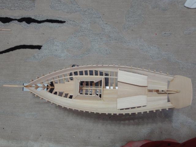
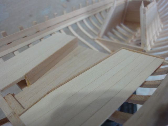
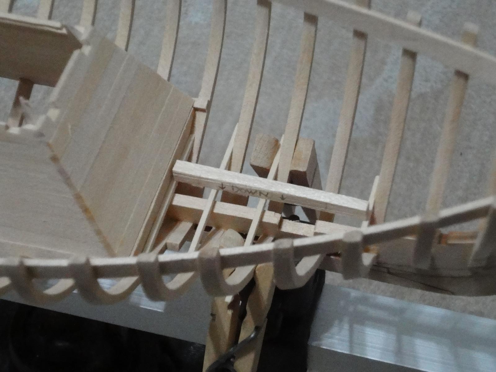
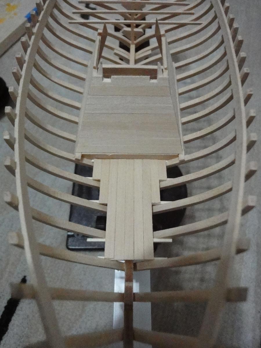
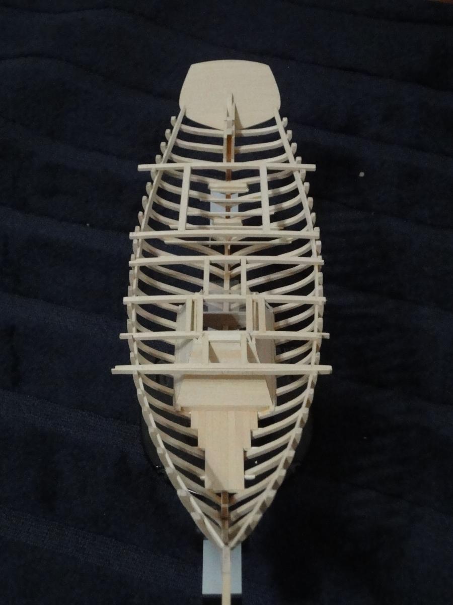
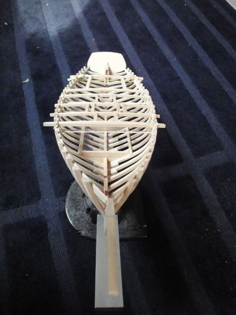
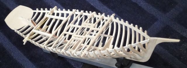
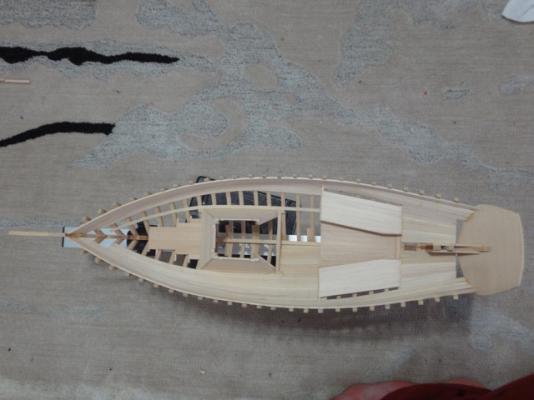
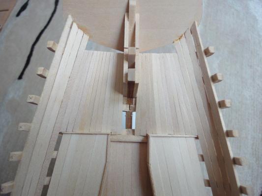
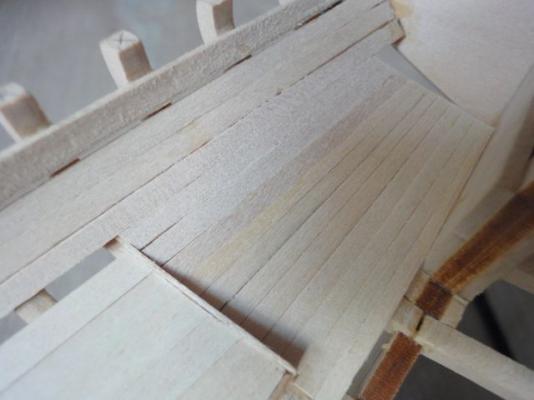
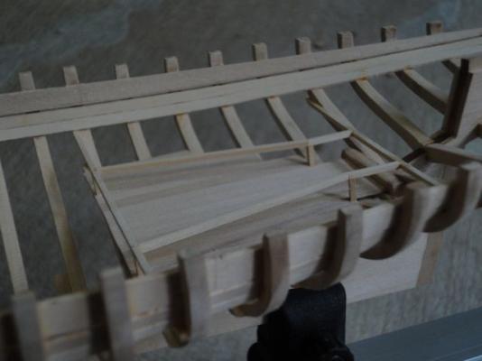
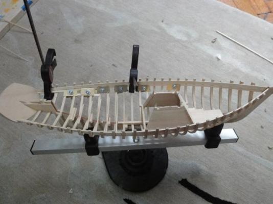
Got a few hours off this weekend and spent some time with Emma. Don't tell my wife. I continued fitting out the interior details. Aft, I installed the "sleepers" which are the beams that support the "sole" (the floor of the rear cabin). Similarly, the beams that hold the forecastle floor were installed. As an aside, any sailing vessel I've been on calls the forward storage area the "sail locker" so I will call it that. It is my boat after all and I'm the captain Here are some detail shots of laying for forward floor boards (joists if you build houses). First, the foremost and after-most beams were installed, taking care to make sure they were semi-level. Then the middle beams were installed using a "checking" plank /straight edge thing. You can see it labeled "DOWN" in the photo. Clothespins were used to hold them in place as the glue set. As another aside, clothespins have a "just right" amount of tension that doesn't dent the wood. My metal spring clamps hold like nothin' but can dent the wood. I prefer a piece that fits, and the "clamp" is simply to hold it in place as the glue dries, rather than force it in place as the glue sets. I almost NEVER use pins. They leave holes that I find unsightly and can occasionally distort the piece being glued in. Here you can see the fore and aft sleepers installed. Please note too that I continue to thank myself for making the deck beams removable. Soooooo much easier to work on the interior but still be able to locate parts according to the deck plan. After laying the joists/sleepers, I was really exited to start some deck planking. I first planked the sail locker. I really wanted to joggle the decking up in the locker there, if not for any other reason than to say "joggle" a few more times. Joggle Joggle joggle. Joggle is a funny word. Alas, I figured that if I were building a real boat, I would just cut the beam ends square, leaving a hand/arm gap so when I inevitably drop my keys down into the bilge, I at least can reach in and get them out of the muck. Here I cut all the planks to length for a fit-up. They aren't glued in yet. The instructions are notoriously poor, so I used my judgement. Then I glued them in using absolutely tiny spots of glue. It looks exactly the same as the non-glued in photo above. It occurred to me when I was stalking others' build logs that you can get lost in the details. I think I might try to end each post with a "big picture" shot or two. So here is a front-on and a port quarter shot with everything glued in and the deck beams resting in place. Cheers! -cb **post updated March 23 to include missing photos from server crash


-
Just happened across your build, and like everyone else said, it is looking great! I had some issues with the hull templates during the build too- the plans didn't match templates and I discovered it later. What is the small dingy looking boat in the background? That looks nice too! cheers -cb
-
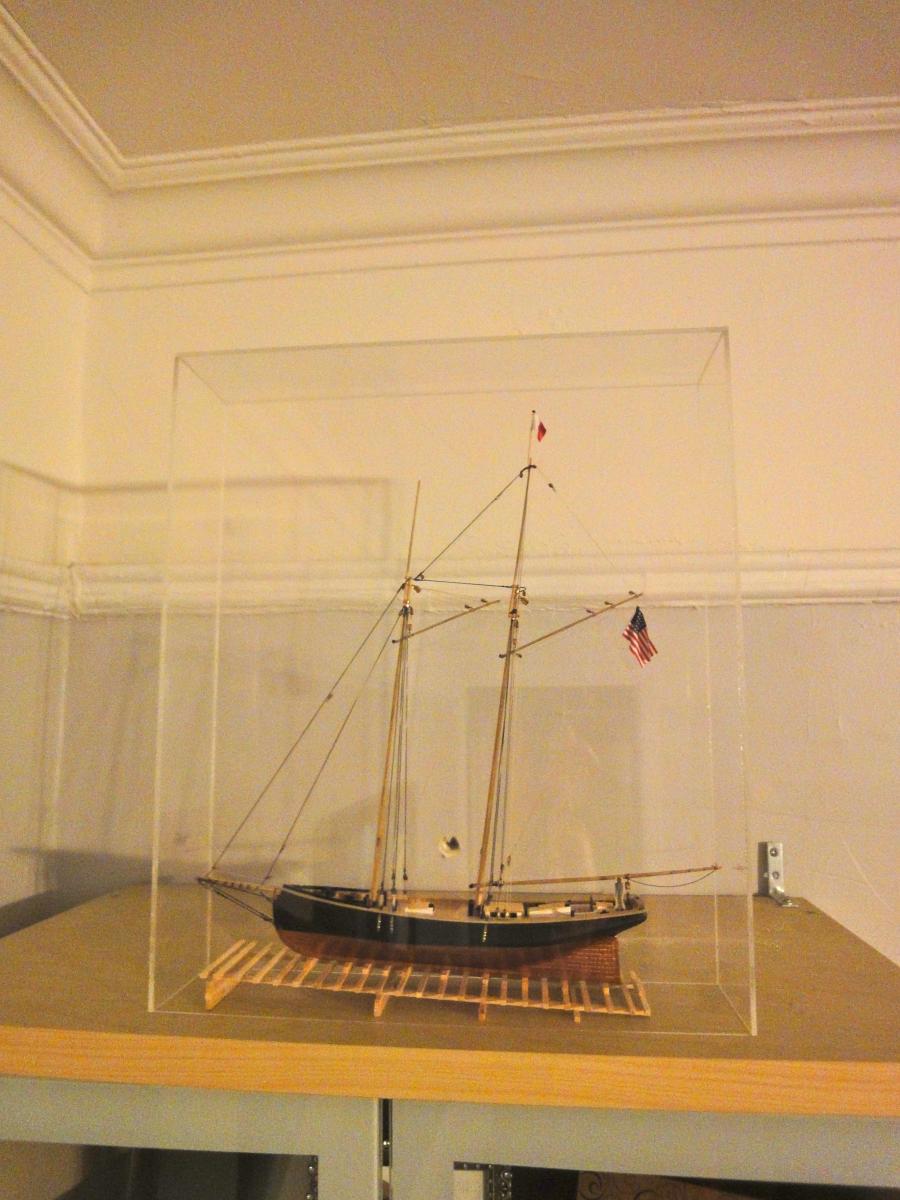
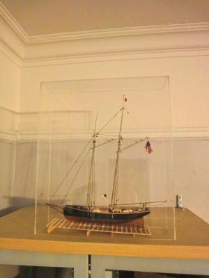
Final Post. I received the acrylic (PlexiGlas) sheet from TAP, and after the pieces collecting dust for a long time, finally glued up the case. I intended to also fashion a nice looking base, but for now, the case just sits over the model. Maybe in another few years… You can read a mini-tutorial on making your own case for cheap HERE. A final parting shot of the Phantom on top of one of our bookcases. Happy sailing.
- 20 replies
-
- 2
-
-
- phantom
- model shipways
- (and 1 more)
-
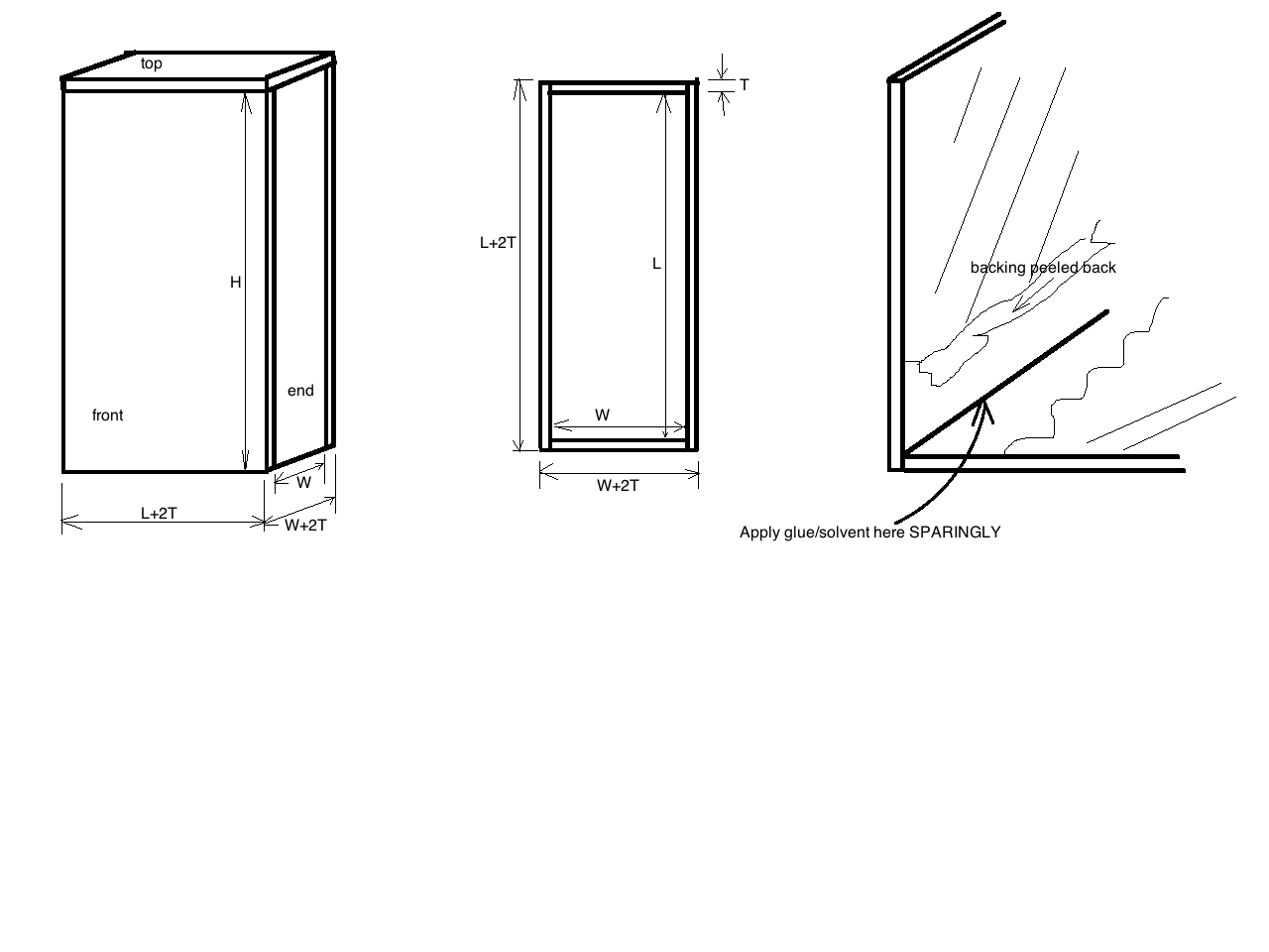
Building a Plexi-glas display case. Just the facts: 1. Measure carefully ($Free) 2. Order up some cut-to-size Plexiglas ($50 from TAP plastics online) 3. Glue it up (Weld-On 3 with applicator bottle and needle, $15 from amazon.com) Total cost: $65 and you can use the glue again next time. Ordering Plexiglas 1. Know the size of the case you want. The base dimensions will be the INSIDE dimensions of the case. -L (length) in the direction of the long axis of your model -W (width) which is the direction of the beam of your model -H (height) which is, um, the height you want. -T (thickness) of the plexiglas you want. The TOP piece will be the size you want the inside dimension of the case, plus the thickness of the Plexiglas. 1 (one) each: L+2T x W+2T The FRONT pieces (the biggest pieces, the ones you will likely view the model through) will be 2 (two) each: L+2T x H The END pieces will be 2 (two) each W x H For example, lets say you decide you want the INSIDE dimensions of your case to be L = 20 inches W = 6 inches H = 24 inches T = 3/32” Therefore you should order One TOP at 20 3/16” x 6 3/16” Two FRONTs at 20 3/16” x 24” Two ENDs at 6 x 24” Next is the actual gluing up of the case. There isn’t much to be said. Study the diagram carefully. Basically, you want to use just enough of the Weld On to be pulled into the joint by capillary action. Be careful not to drip the solvent onto anywhere but the joint. Pull some of the protective backing from the plexi sheet where your joint will be, leaving an inch or so. Leaving most of the protective sheeting in place means less chance of scratching and less chance of dripping solvent/glue onto the viewing surfaces. But if you don’t peel it back a bit from the edge, capillary action will suck the glue up onto the viewing surface between the sheet and the plexi. I used a carpenter’s square and masking tape to hold everything in place while gluing. It doesn’t seem to matter if you apply the WeldOn from the inside corner or the outside of the joint; it gets sucked into the seam really well either way. I think doing it from the outside is less chance of dripping onto the viewing surfaces of the case. Only do one joint at a time. I started with attaching the TOP to one of the FRONTs, but it doesn’t really matter. You may want to sand the edges a bit with regular sandpaper to make the edges really smooth. I did this, though I’m not sure it accomplished anything. The glue dries really fast. In about 10 minutes, you can do the next joint. The whole box took me about 1 hour to make. ----------------------------------------------------------------------------------------------------------------------------------------- Background and other Pointers: Your model ship deserves a case. I looked at my Phantom sitting on the cabinet for over a year, watching it get dusty, before I figured this out. Some quick online research and, holy cow, a custom case is about $400 to start! Wow! That is 4+ times as much as the kit cost. And it is, you know, $400! So, this option fails goal #1. I then looked about a bit more, and came across modelshipcases.com where you can buy an e-book detailing how to make your own gorgeous custom cases. So I bought that and it is a pretty good resource. Unfortunately, you really need a full woodshop or, at least, some basic woodworking tools like a table saw and some space. Maybe someday, or at least if I had a proper shop, but for right now my “shop” is the floor of my tiny NYC apartment and all of my “equipment” has to fit into a file box. So that was a fail on goal and #3, so this option didn’t work either. So, what is left? Buying one is out even though it would look the best. Making my own from the available plans would be great, but I don’t/can’t make that happen so that is out. I guess I have to make one myself, by my own design. Dimensions: Measure your boat. Several online sites suggest adding an extra 4 inches length-wise and 2 inches or so height-wise. My Phantom is a pretty small model and I think that would result in a way to big case. So I sort of settled on 14 inches long by 3.5 inches wide by 16 inches high. These are INSIDE dimensions (important!). Cutting Plexi-glas. This is where I failed. There are three options. 1. Order it cut to size. This is, by far and away, the best option even for my very cheap disposition. It will come to your door perfectly sized, edges crisp, and for about 20% more than if you bought the material yourself. Just do this. Seriously. If you really are that cheap and choose not to, read on, but be warned. 2. Cut it yourself with a scoring tool This is the first method I tried. I had previously cut some plexi for another project, and it was easy at the time so why not. But it was long enough ago that I forgot all the fine details. I purchased the raw material for $30 tax included. The scoring tool I already had but that was about $7 at Home Depot. Ordering the material cut to size (see #1 above) was $41 shipped. Honestly there isn’t much of a difference between about $37 and about $40. There was a huge difference in $40 and $400 to have someone else build one for me though. If you still want to save that $3, you can do so as follows: Use any convenient straight edge. I put the plexi on the floor right on the carpet of the living room, put a board on top of it as a straight edge, and stood on top of the board to keep it from moving. SCORE AT LEAST 10 TIMES. I cannot emphasize this enough. If you don’t, when you break off the piece the crack will go in a random direction and mess up the whole thing. Then flip the thing over and score a few times on the other side of the plexi. Another possible (likely) scenario is that you are scoring along, the first 5 or 7 scores feel good and go one right on top of another, then the eighth score takes off away from the straight edge you are using and BAM. Big ol’ nasty scratch across what had hoped would be a useable piece of Plexiglas. Into the scrap bin! But, like me, you try to salvage it, and instead of breaking cleanly along the 7 scores, it fractures across the entire sheet of raw material, and the ENTIRE thing goes into the scrap box. Just order it cut for you. 3. Cut it yourself with a table saw. If you have a table saw (I don’t) this could be a way to go. But you’d probably need a special blade, it might melt instead of cut… I don’t know. Just order it pre-cut for you.

-
Ramming a new powder charge into an incompletely swabbed gun can result in premature explosion if bits of burning embers are left in the bore. This could be most unexpected, injuring people.
-
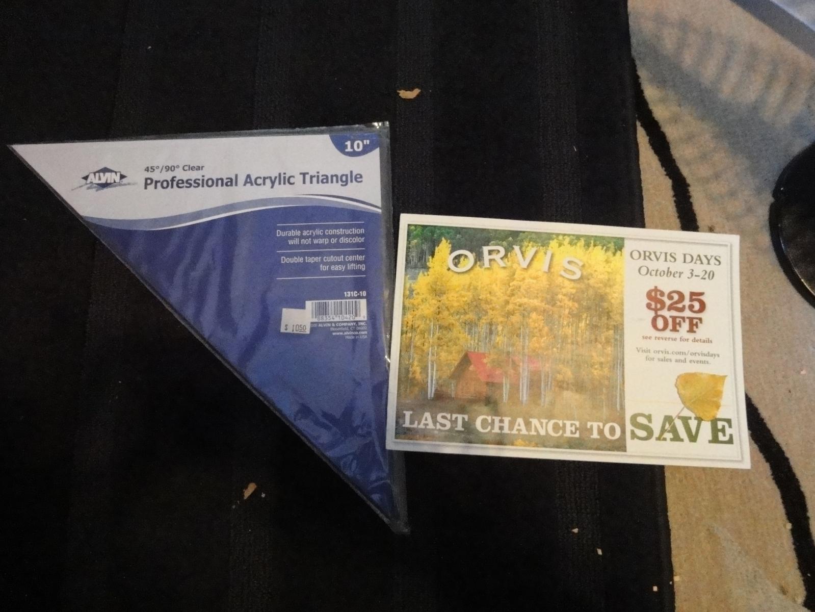
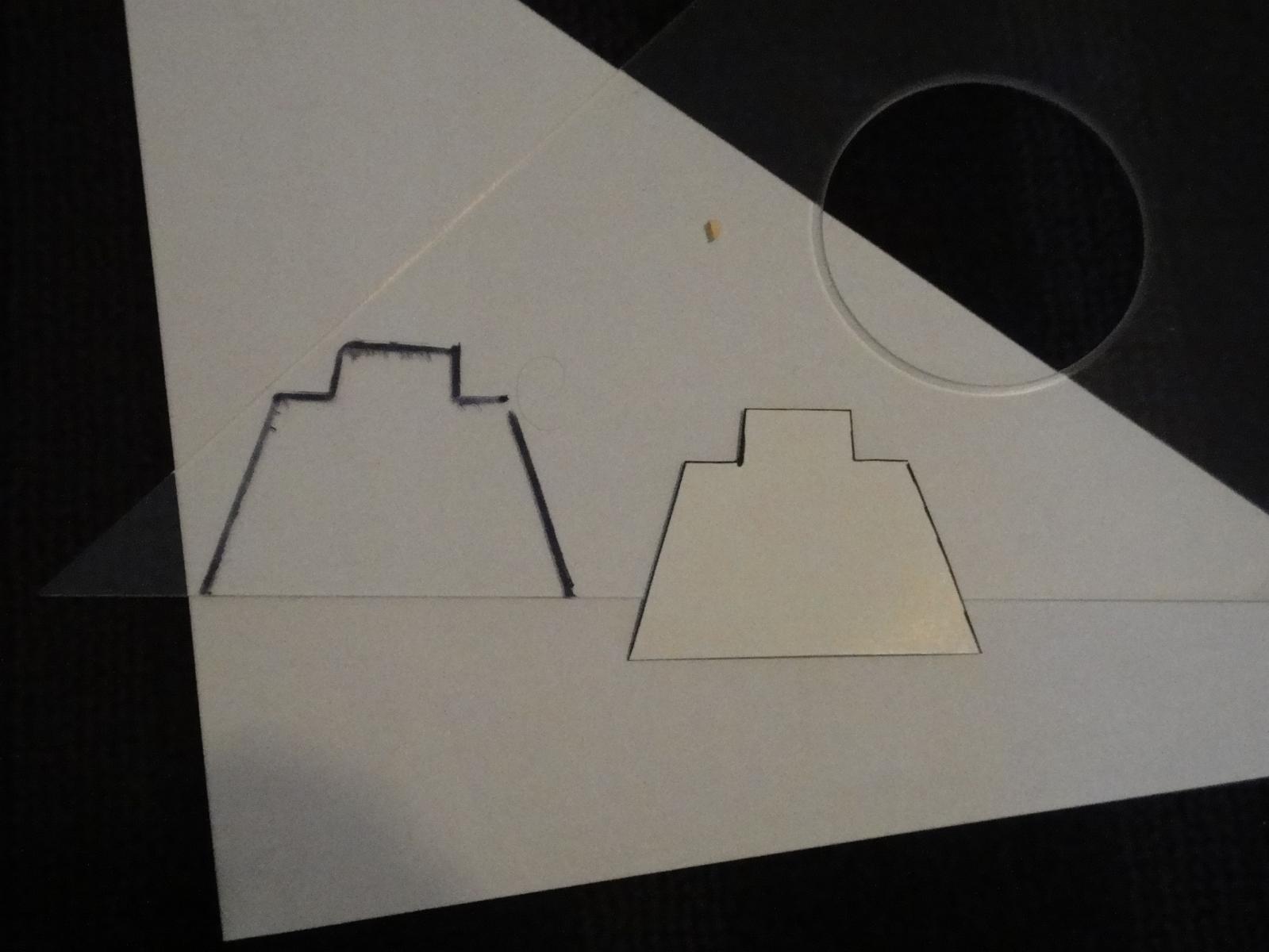
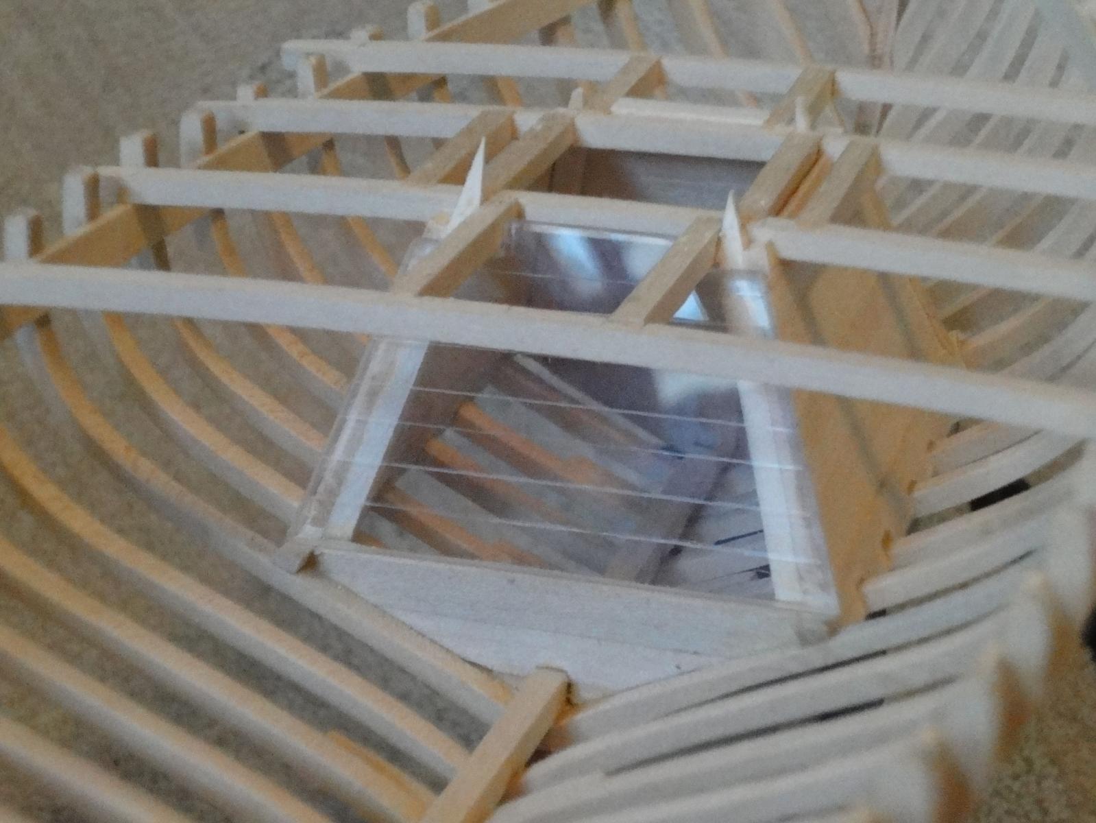
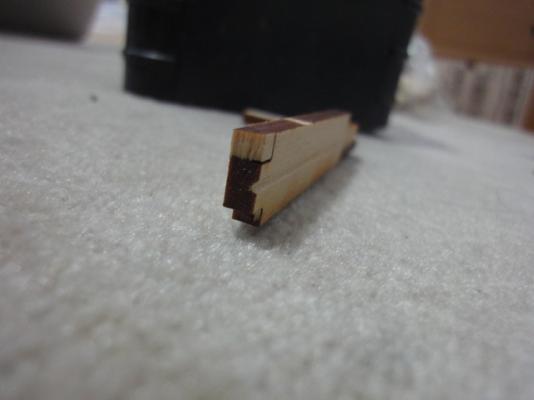
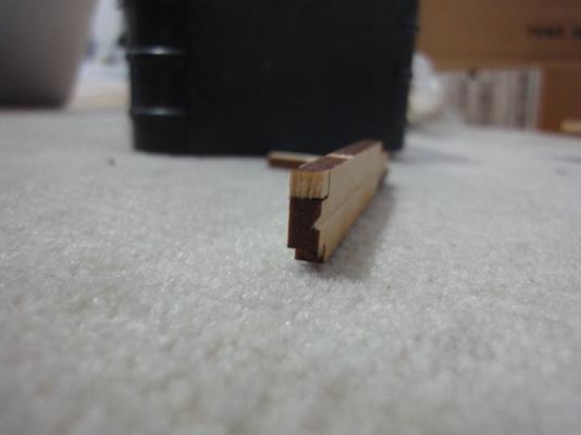
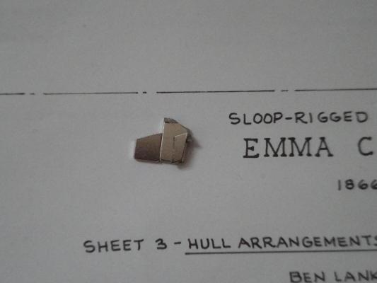
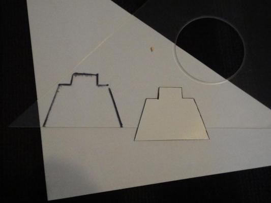
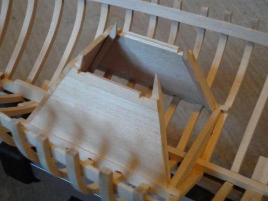
Mini How To: Making an acrylic faux-planking piece After deciding to attempt a clear “vista” section of my model, I immediately looked around for pieces left over from my last acrylic-working shenanigan debacle (As seen here). Turns out I was so peeved I threw all of it away, so off I went to the local art supply store. Turns out an approximately 4x6” piece was about $15. Yikes. So I looked around, and instead bought this architect’s triangle for “only” $10, with the idea of cutting it up and harvesting its parts. I also re-purposed a junk mail flyer for template duty. Well, junk is a strong word. I strategically avoided cutting into the coupon itself, because I’ll be damned if I’m going to miss out on $25 off a $50 purchase next time I go to Orvis. Moving on. Turns out that making the template took much longer than I expected, but going slowly I eventually ended up with a very good template that was transferred over to the acrylic sheet. Next, I used a Dremel tool with a cut off wheel (Always wear safety glasses!) to carefully rough out the shape as close to the line as I dared. Then, using a flat file, I cleaned up the edges and beveled them even. This took less time that I expected, but I expected it to take forever. It still took a long time. It was actually surprisingly easy to make the edges an angle, rather than pure 90 degrees. The bottom side, in particular, looked weird without an angle filed in, and left a big gap. All the edges were lightly chamfered, giving it a surprisingly professional appearance. I expected the whole thing to look pretty bad, but I think it looks darn right nice, much better than expected. Sometimes you even surprise yourself. Then I fitted it up, and the thing was so convincing that it looked like nothing was there at all. So I carefully marked where all the real wood planking was, and scribed some lines into the acrylic using the tip of a small round file to simulate planks. This is the same photo as my previous post.


-
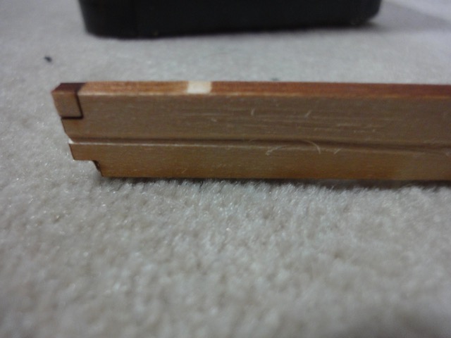
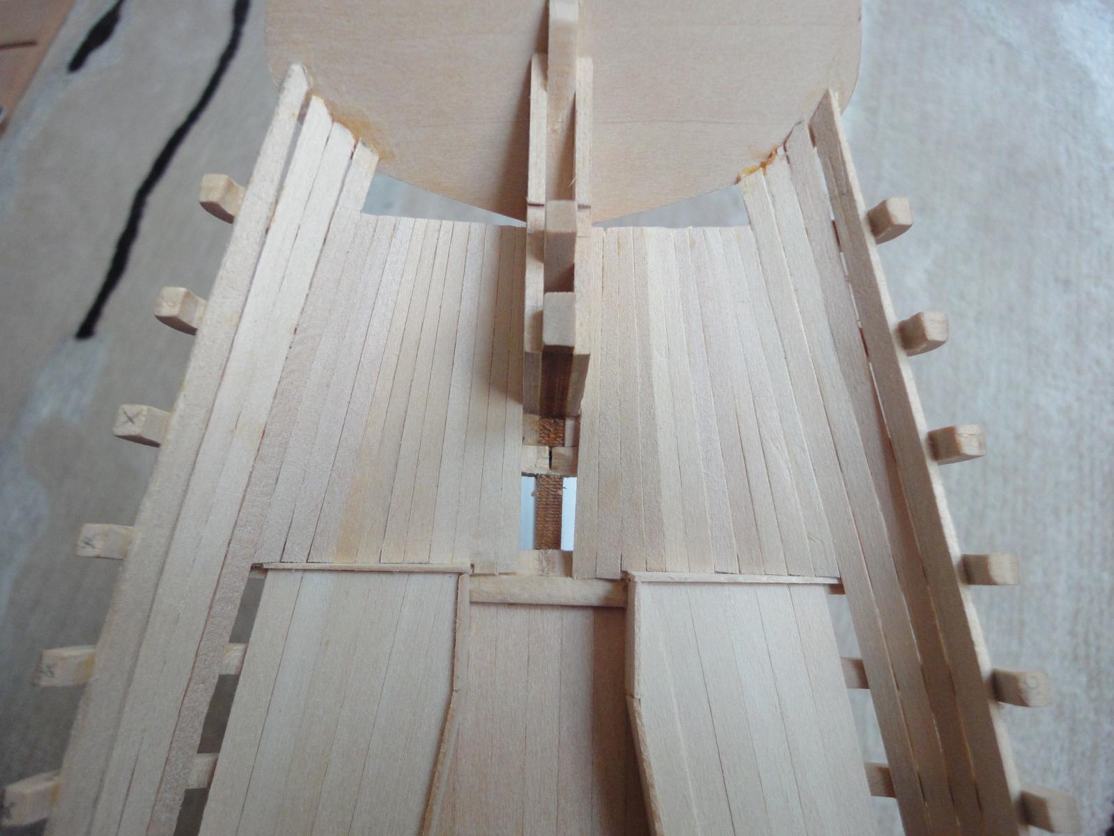
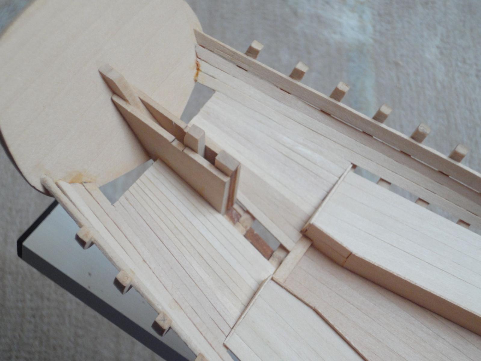
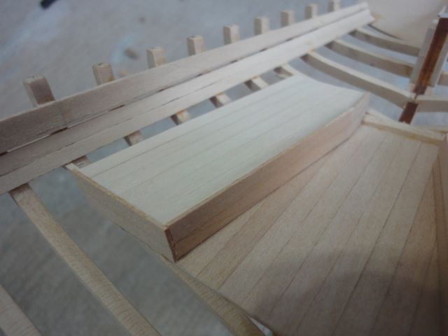
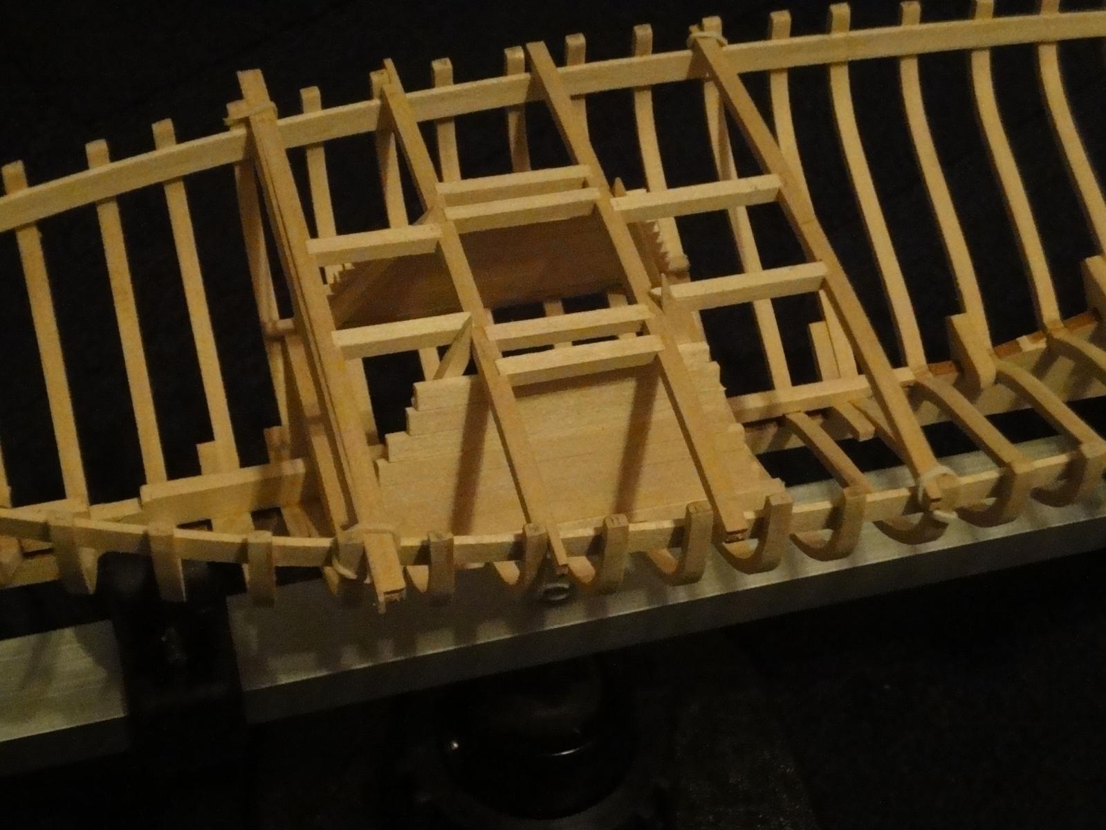
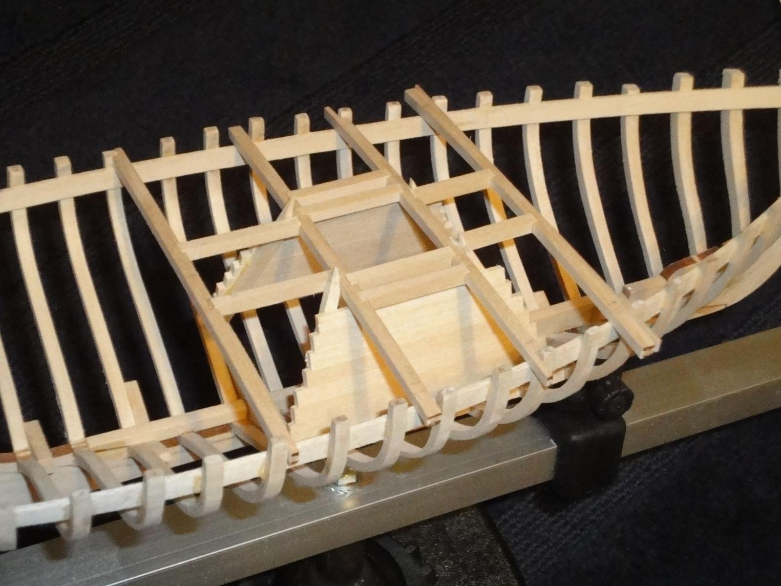
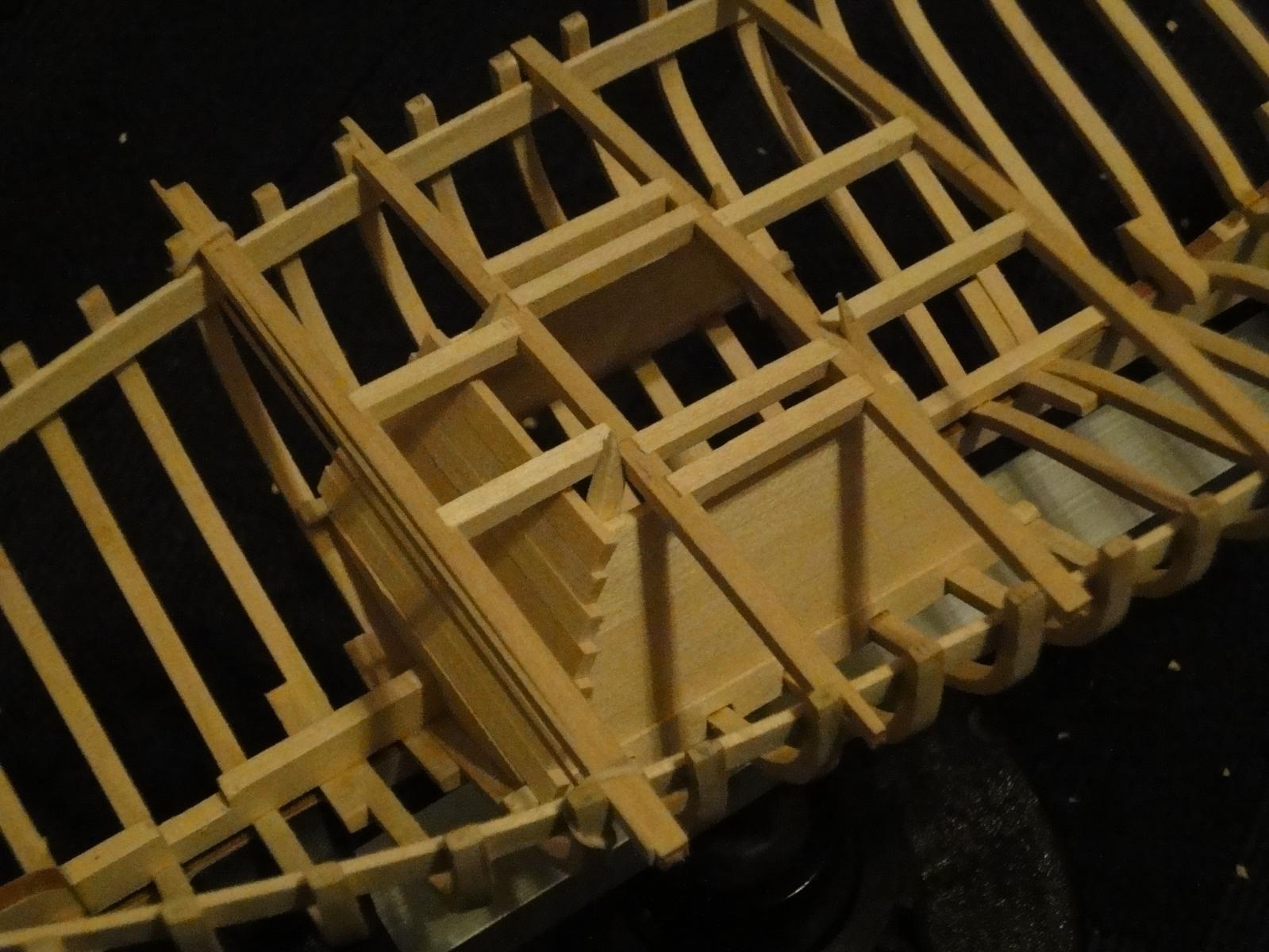
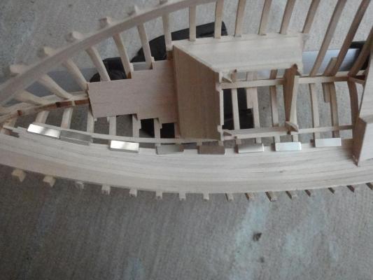
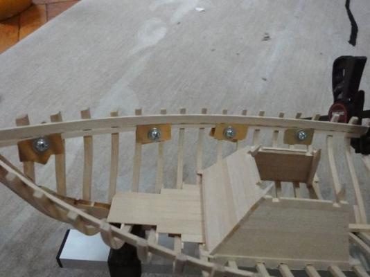
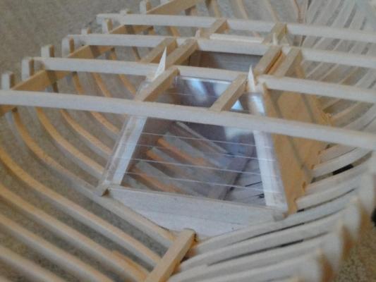
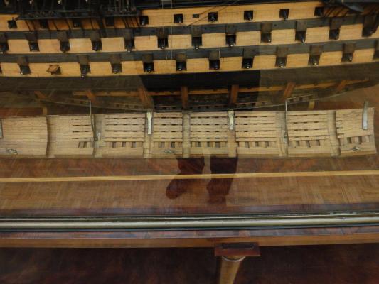
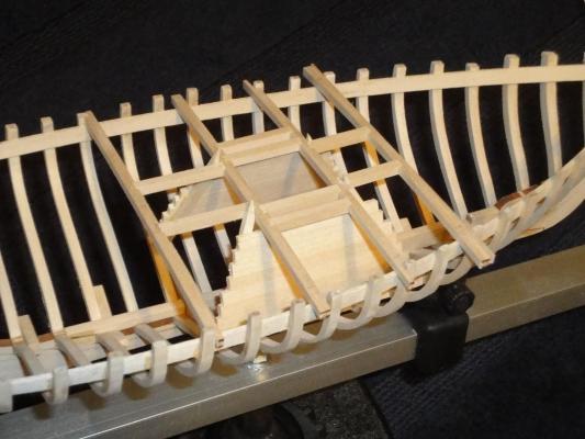
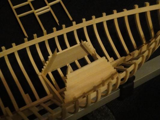
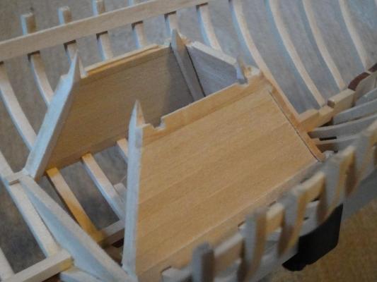
Wayne, I’ve been following your build and it looks great. I have been thinking about “unique” ways to show the work that went into a model. Here is a photo from the Muse National De Marine (something like that!) in Paris with a very elaborate cutaway system. As detailed below, I hope I came up with something subtle but effective. And now more photos and stuff. Another day off, another bit of progress on this wonderful model. This time, I tackled the wet well. As you probably know, this is a very unique feature to this particular historical boat, so I really wanted it to shine. As I mentioned above in this build log, I was considering a “lift off” section of the deck to showcase the plank-on-frame construction, while still fully fitting out the interior of the boat. Well, I decided that I definitely wanted to do that, and thought it would be a good opportunity to showcase the wet well. I will also mention that, during this point of the build, I’m really glad I didn’t glue in the deck beams, as many parts required repeated fitting that would have just been aggravating if I had to carefully snake the bits in through the ribs and deck beams. I highly recommend this method to anyone building this (or any other, really) model! Enough blah, on to the photos. Here I’ve cut the wet well planking to approximate length and simply stacked them up to see what they looked like. Here, I decided that the fit between planks was so nice with the kit wood that I would just glue the wet well planking to the corner posts, not to each other to avoid glue squeezing out and messing up the wood. This, too, was really the way to go because, in the finished shots later, my wife thought it was a solid piece of wood! Even in real life she thought that! Nice. Speaking of the corner posts, they were interesting builds, with several complex angles that had to be cut and sanded “just so” for a good joint. They are glued down at the bed logs, but “floating” on top at the deck without glue, though the are held in place quite well by the fit. Actually, sharp eyed viewers will not that the corner posts are supposed to extend fore and aft to sit directly on the frame, OUTSIDE the bedlogs. Then the wet well planking is supposed to go outside the corner posts on the port and stbd sides, but inside the corner posts on the fore and aft ends. Well, I messed it up and it was too late to fix it, so I did what I always do. Move on. I think, aside from you guys, no one will ever know! Here is a shot with the wet well planking glued on port and stbd but the deck popped off. Here I have started fitting the forward side wet well planking. At this point, I realized I didn’t have enough of the proper sized wood to plank up the after side. The, I got to thinking! Uh Oh! With the interior of the craft eventually covered in ceilings (ceilings are the equivalent of hull planking, only on the interior side of the boat) there really won’t be any way to see the hull frames, even if I have a lift-off deck section. So, what I decided to do was something more fun. I “planked” after side with a custom cut and fit piece of acrylic. This will allow one to peer in through the lift off deck into the back of the wet well, showcasing this unique feature as well as giving a glimpse of the framing inside the wet well also. Well, that is the theory at least. For a mini how-to, please see the next post! Here you can see the ends of all the planks trimmed to final dimension. I started by roughing it down with a sharp #11 blade, the realized that I had a lot of control with that, and sanding sort of de-highlighted (?) the plank ends, making it further look like a single sheet of wood instead of individual planks. So the finish you see is the result of shaving them down, not sanding. Minor detail, but (hopefully) interesting. You can also see the top-most wet well planks, and the complex shaping and fit-up needed. Again, here, having the deck NOT glued in was a godsend. Those three (P, S, and Fore) took as long to make as the rest of the wet-well put together! Finally, a parting shot of the completed wet well, with acrylic after-facing “planking” in place. Cheers and happy building -c


-
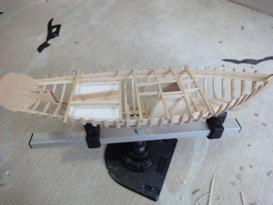
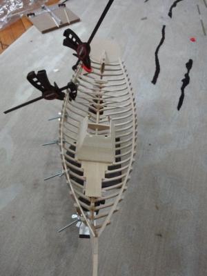
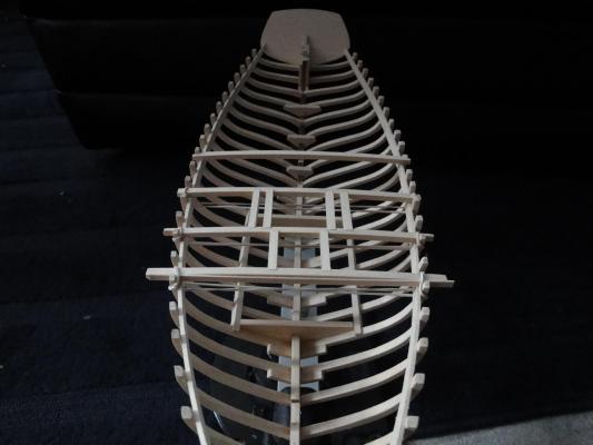
After a really long time, I finally got a day off to put a few hours into the ECB build. I made a few more deck beams and hatch grating frames. The beams and whole deck really are not attached to the hull at all. I'm doing this so that I can pop the thing off and work on the interior details without fighting very much. For now, rubber bands hold everything in places. I think the deck is constructed enough that I can get the alignment of the wet-well frames right. This construction method has me giving serious thought to leaving at least one part of the deck as a lift-off piece in the finished model so that you can see all the interior details. One school of thought is "if I built it I might as well look at it." On the other hand, I recall seeing an exhibit at, I believe, the Naval Academy model collection where they took a surgeon's endoscope and looked in a period ship model to show that the entire inside was totally fitted out with ladders, gratings, tables and chairs and everything, even though it was impossible to see in the completed model. I think this is a real quite dignity to that! The building of the model is the reward I guess! Thoughts? -cheers

-
I too went from vernier to dial and now digital. I also use it for precision metalworking. However, I must say that these instruments are lifetime investments. You will not be sad if you save up the $100 or so for a quality American or Japanese made (Starrett, Browne and Sharpe, Mitutoyo etc.) calipers. Others may disagree, but I have several precision instruments purchased by my grandfather that are as good as the day they were made. Then you can grind down one of the jaws on your old caliper (Vernier or otherwise) and have a very fine precision scribing gauge in your toolbox.
-
Don and Yves, Regarding your transom questions, I had the opportunity to take several photos of the real Emma a month or so ago, maybe they will help? http://modelshipworld.com/index.php?/topic/3221-emma-c-berry-photos-at-mystic-seaport-2013/ cheers
-
All I managed to accomplish on the Emma over the last, wow! 2 months! was framing in some hatch gratings. The deck beams are still not glued in- I plan on building the entire deck as a removable ift-off thing to make building the interior details easier later on. Only at the last minute will it be glued in. I attempted to do the true mortise shape with the little hook on the end, but it is so small I couldn't cut it without the "hook" flaking off because of the grain. Maybe with a different wood it would be easier to do? After about a half dozen tries I gave up. So I settled on simple square notches, and I think they are turning out pretty good. Of course, they will all be covered over with planking anyway... Happy building --craig
-
Veeeery slow progress for the last couple of months but I did manage to get out to the Charles Morgan launch party at Mystic Seaport. While there, I took a BUNCH of photos of the details on the Emma. Please check it out! http://modelshipworld.com/index.php?/topic/3221-emma-c-berry-photos-at-mystic-seaport-2013/
-
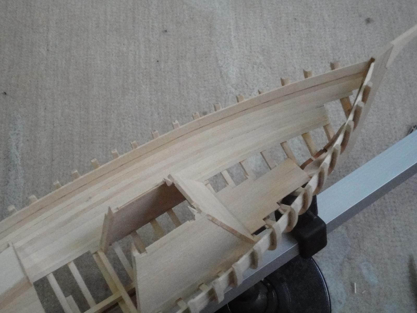
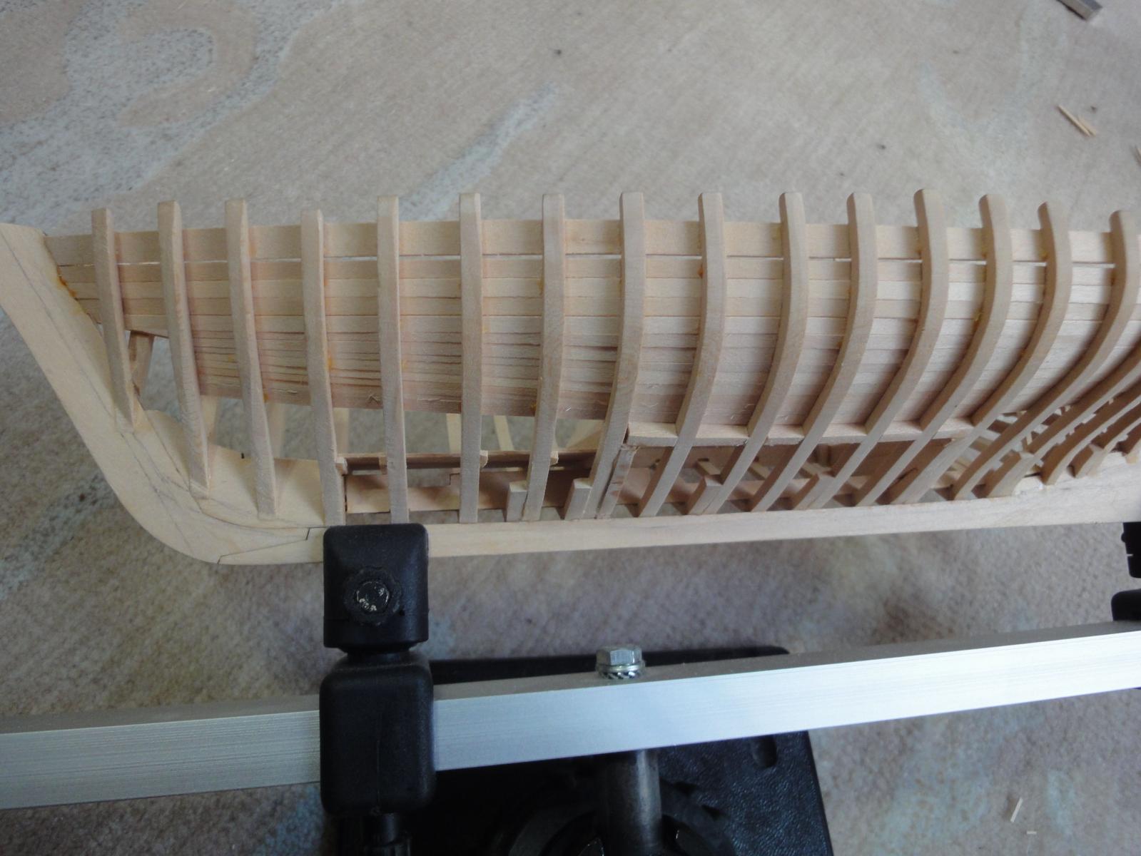
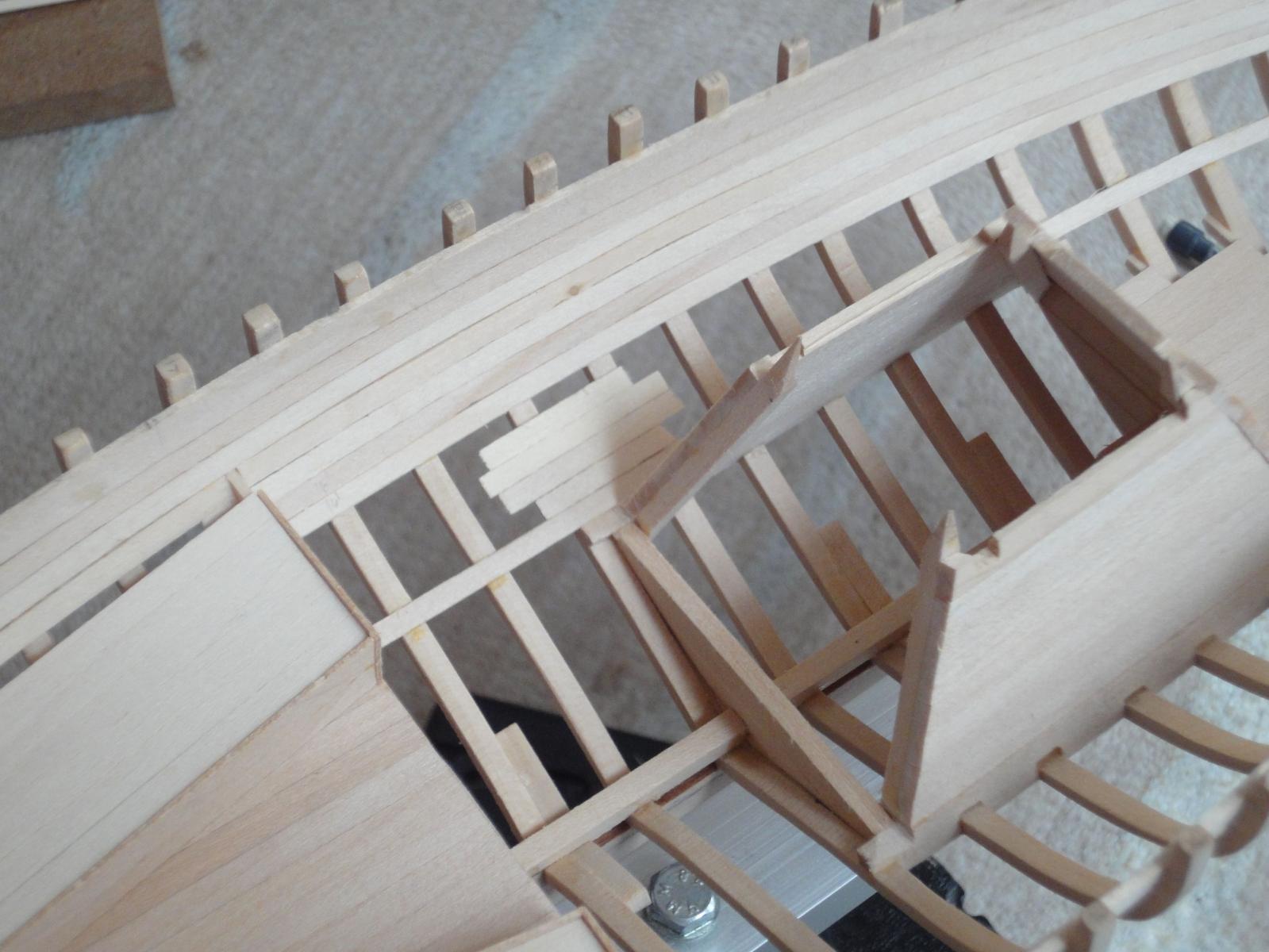
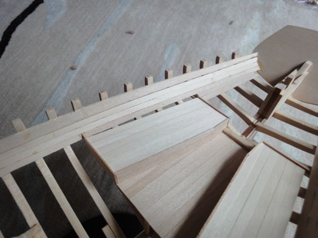
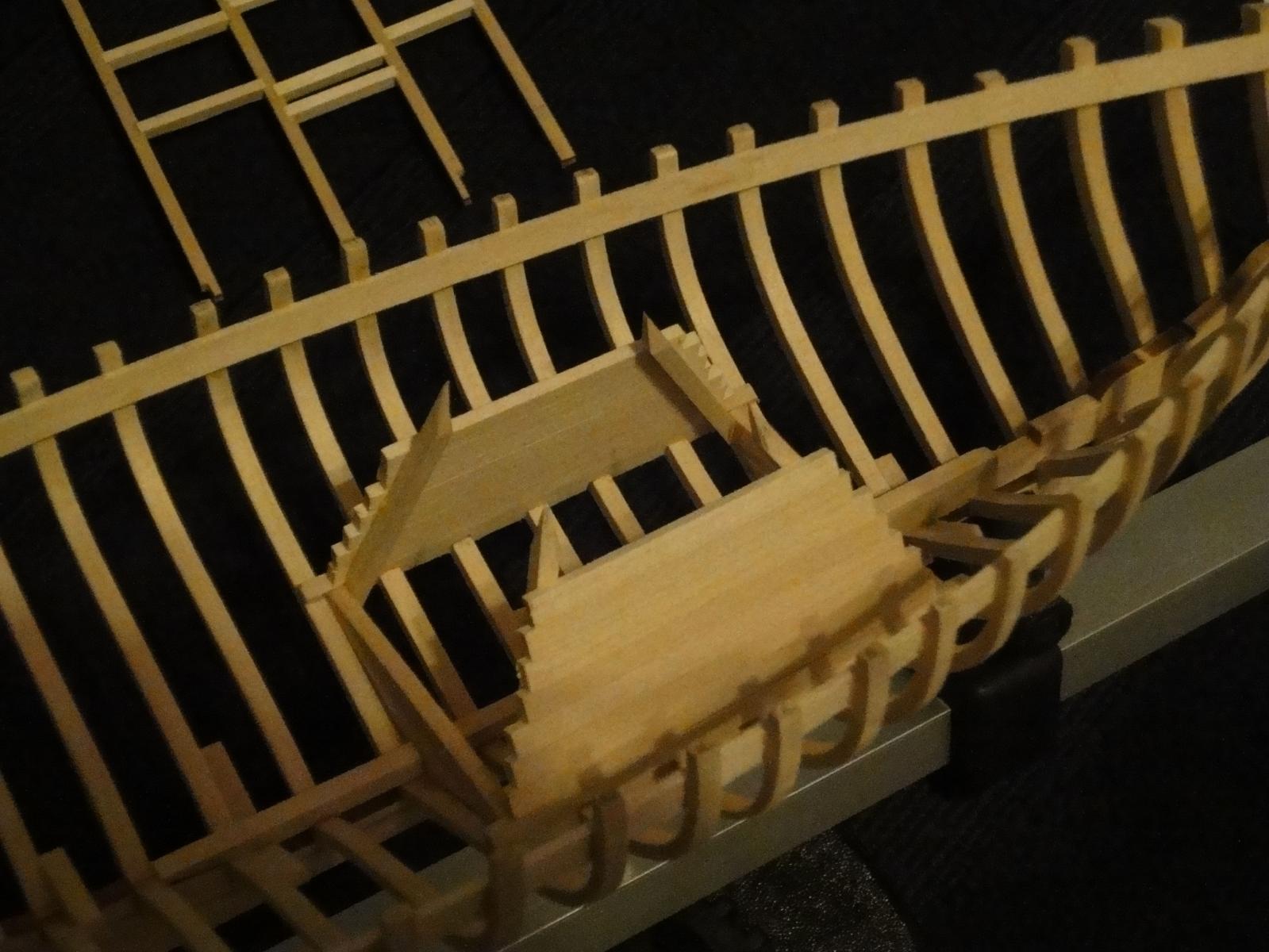
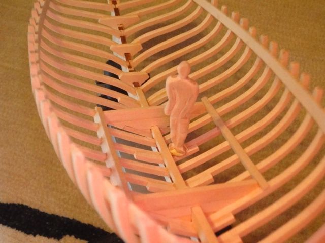
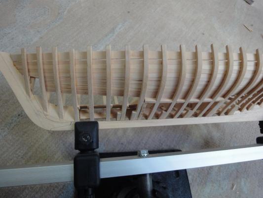
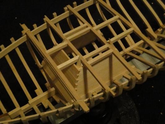
Russ: thanks for the explanation! I knew there had to be a reason. Building continues. I framed out the bottom part of the wet well which involved making a kind of interesting piece. I held the raw wood up to the frame, traced the outline with a pencil and cut it out. I fully expected to have to make a few of these before the fit was good, but lo and behold it fit up great the first time. Sweet! The end was left long to facilitate fenagling it into place. In the second photo you can see it fit into place. The deck beams aren't glued in yet- they are held in place temporarily with rubber bands. I also tried to carve up a figure so that there is a sense of scale. The pose is anything but natural, and despite trying to make a decent relief, it still looks really flat. Meh. At least it is 6 scale feet tall. After I got done framing the bow end of the wet well, I double checked the plans and noticed that I had framed the wet well to frame #8, not #9! Yikes! So, after about 30 seconds of thought, I decided that this particular ECB will simply have a bigger wet well than most. As far as I can tell, the only thing forward of the wet well is a storage locker that will barely be seen in the finished model anyway. The last step was to re-fair the outside of the hull. Until next time- Cheers! --craig