


Thistle17
-
Posts
1,042 -
Joined
-
Last visited
Content Type
Profiles
Forums
Gallery
Events
Posts posted by Thistle17
-
-
Thanks Chuck. It seems to me I am loosing some concentration in addition to being too cautious and over thinking things as you say.
Believe me I am reading the monographs, especially yours.
I came back to the model after I'd walked away for an hour and figured it out. Of course when I trim (sand) back the 'C' frames they will give me the relief I need and when I bevel and fit the fillers all should come out well. I have come to be so sensitive to the fit of the elements since if not correct it will be a disaster with the construction of the quarter galleys.
What I ended up doing to get the transom frames to have the right fit and sit well was to remove bulkhead 29 and replace them with hand made new ones. That cured almost all the problems with frames "'A' and 'B' as they were too sloppy a fit with all my prior tunning.
Joe
- Ryland Craze, glbarlow, FrankWouts and 1 other
-
 4
4
-
I believe I have reached a milestone in that I have been able to fit all the stern frames correctly and glue in most of them (save the 'C' frames). I have used just about everyones suggestions along the way to do so. Photo(s) to follow. The reason I have not glued in the 'C' frames is that thinking ahead to the quarter galley, fill pieces that will be glued to the inside of the transom element, I am a bit hesitant without asking the following:
"Knowing that the planking is 3/64" the galley fill piece edge has to butt up aginst the planking (I understand I have to taper that edge carfefully for a good fit against the hull). So I assume that one needs to account for that 3/64" plus a TBD amount so the filler creates a relatively even lip for the galley rear window. Now the galley filler inside stile is 3/32". That tells me I have to remove just about 3/64" from that stile. Am I correct?"
Joe
-
-
Thank you all for your ideas and thoughts. I intend to employ them in the next round. I ordered the kit parts this AM and have patterns cut for potential replacement bulkheads should I need to go that far. I saw a method on the Tally Ho restoration (YouTube) involving the precise layout of critical opening cutouts of covering boards on her deck that might be something worth trying out as a jig. So Edward we will see.
Joe
-
"DON'T TRY THIS AT HOME!". As one might have guessed my idea of assenbly of the transom in the manner I described while not a disaster was not a complete success. It actually fit the bulkhead slots but as I moved outward from the mid transom frames, especially the 'C' transom frames, it became an assembly in tension.
So with 'hat in hand' I reordered Chapter 1 parts again and will start the process over.
I have found this segement quite a challenge as there are so many ways that this can go wrong. Am I the only one who has tripped up on this?
Joe
- glbarlow and FrankWouts
-
2
-
Chuck I understand your doubt. I share it. I did forget to mention that I am tapering the upper stern frame fillers as the on line instructions relate and I am using the guides (1 through 5) to help in the contouring. As I proceed I am taking the partial assembly to the model and testing the fit. So far with one of the 'B' frames correcctly postioned it fits and fits comfortably. As we have discussed my start up has been unconventional and I am paying for that. It was a hard lesson learned that will not be repeated. My escape will have to be some level of do over if it is a disaster.
Joe
- glbarlow, FrankWouts, Chuck and 1 other
-
4
-
Thanks Glen for that perspective. I did wonder about how the effects of trimming to fit was going to turn out in the end, Your input gives me the caution I need to hear. Interesting comment on the U and W bulkheads. I will watch that as well,
Joe
-
Let me lead in with the following statement before I get into the methodology I have adopted for the stern framing. " In no way am I making any disparaging comments as to the fidelity of the Syren kit parts in my comments herein. I have always found the parts to be well designed and manufactured."
Having said that I think many of you might agree that the Winchelsea transom is a bit tricky to assemble and fit correctly. Simply put, it takes quite a bit of care and trial fitting to get it to come out correctly. Not withstanding it all has to take place in mid air!
Well it was a bit more of a struggle for me under my circumstances. The problem is unique to my "framing construction" and would not affect others. I only share it for some of you that may be having trouble with "in air" assembly.
After a number of attempts to fit the transom frames and fillers in place while all elements were stepwise fit together on the frame. I had to abandon that approach. Before I get further into it I should also say that sanding, chiseling and filing the stern frame slots on #28 and #29 bulkhead resulted in some loose fitting slots. That made the "in air" assembly yet more awkward.
So I resorted to an "on the bench" approach. I copied and cut out the stern layout drawing on page 1 of the drawing set. I began with stern frame(s) 'A" and the associated filler for these frames and overlayed them on the drawing cutout. There is no filler tapering required on the filler but to have the frames correctly align I did have to trim the mid filler a bit. Now before going on one has to realize that this is a 2D drawing of a slightly curved transom and has not been adjusted for the concave effects ( I believe this, as the "port holes" in the frieze or the transom covering line up quite well).
Successively I am working my way outward and at each step checking by fitting on the stern and with the transom cutout. Note in the picture that the port side filler has yet to be trimmed to fit.
I have my fingers crossed that all will come out in the end. Else I may have to repurchase some parts. That will be humbling!
Joe

- FrankWouts, westwood, Ryland Craze and 1 other
-
4
-
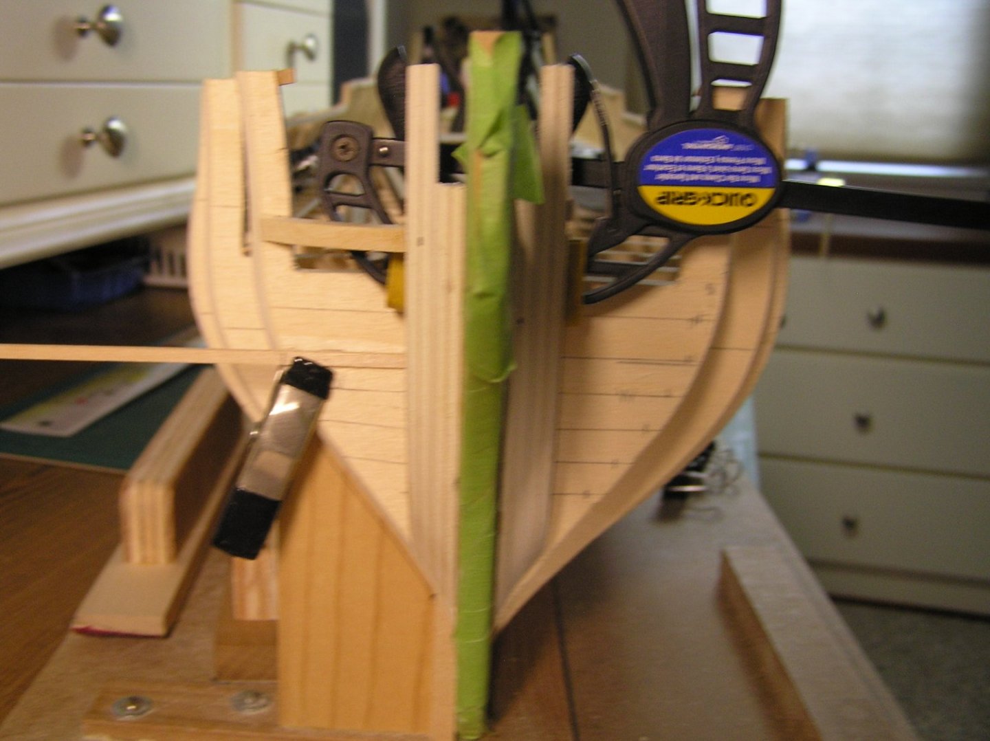
As I continue the fairing of the hull I spent some time on the bow on the starbaord side and was pleasantly surprised at how it turned out. Methodology was the key for me and the batten trials has served me well. I did extend my bow filler layout method to the port side in the following manner.
Before I permantly glued in the starbaord elements I ensured that the taper on both the exposed and backside profile of the port side matched the starboard elements. I then extended the perpendiculars I had inscribed on the starbaord topside element to bulkhead 'W' on the port side. Then using the ;story pole' shown clamped to the strabaord side I marked the taper that would 'dial me in' on port side and made the tick marks shown. In theory this will give me a near identical bow geometry to plank.
To my way of thinking this simple method nudges me away from the 'eye balling' I have done in the past that has not always turned out for me.
Joe
-
Hmmm! I didn't read the monograph thoroughly enough or should i say I did not spend enough time on line where at times more detail can be found.
Of course that explains it. Another lesson in more deliberate execution. Not an excuse but at this time I can only spend an hour at best at this and the on again, off again approach does not lend itself to the build. Thank you.
Joe
- glbarlow and FrankWouts
-
2
-
Good advice Glen.
I was playing around once again with the transom framing alignment. It is coming along but I came upon something I wonder if people can enlighten me on. I cleaned up the transom fillers and dry fitted and clamped them in place save the outer ones port and starboard. I was a bit surpirsed to find they were a bit too fat. Certainly way to fat to be tweaked. I would say they were 3/32 inch too wide. I laid them on the drawing and found that they are too wide there as well by the same amount. The drawing shows vertical lines on the pieces. Now they could be trim lines. Has anyone had to trim these per the drawing?Have I missed something here?
Joe
-
Back to fairing the hull after my stumbles with the transom frame(s) alignment. I went back to concentrating on the bow bulkheads and fillers. I find this area particularily fussy to work as one is trying to shape the bow mostly through an itterative trial fit process. The battens come in handy for this stage so they must not be neglected in the shaping effort. Observing how the batten lays against the fillers and the first two bulkheads is always a clue to the trueness of shaping.
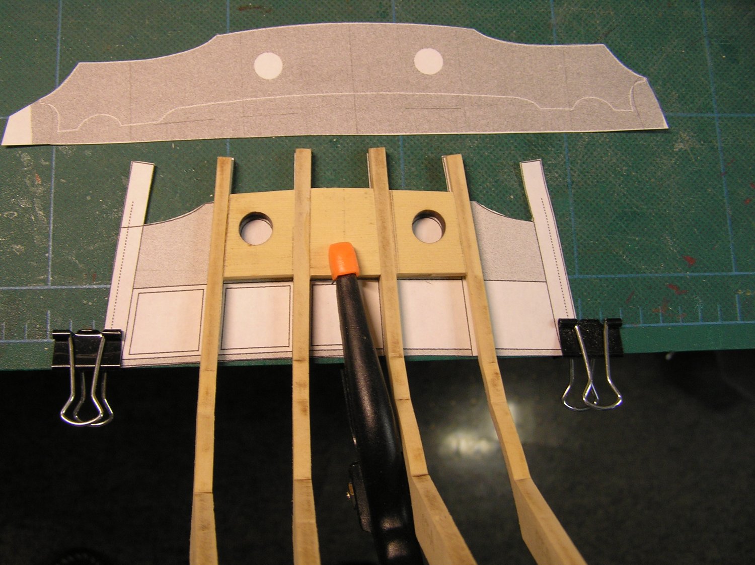
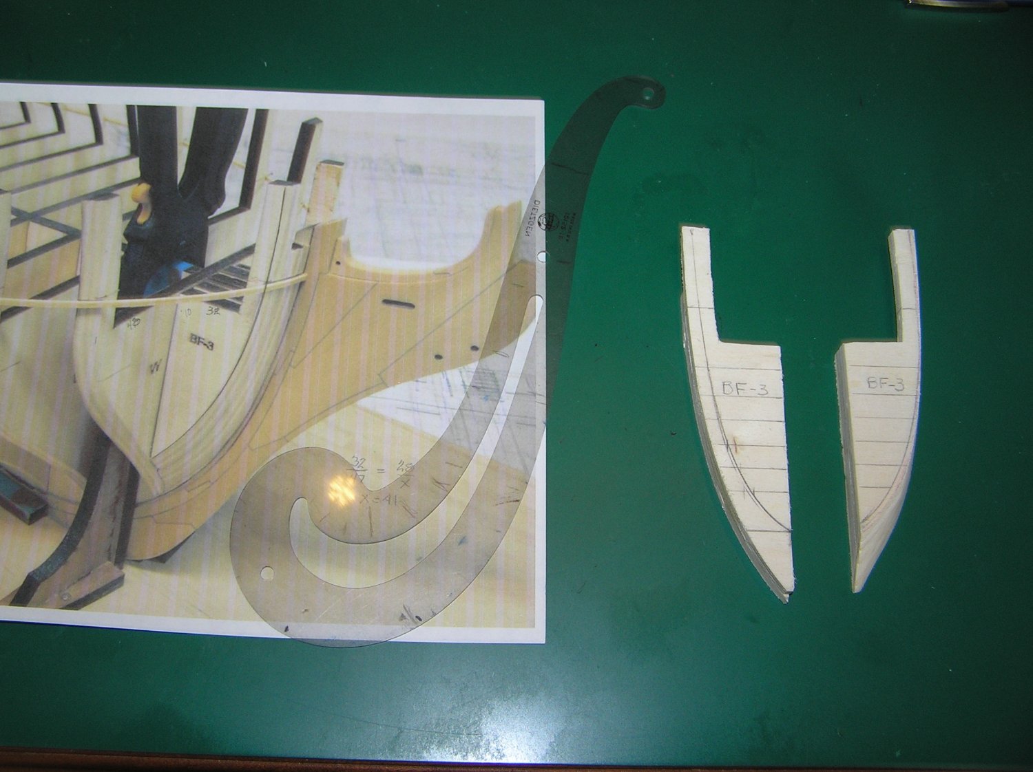
To make things just a bit more complicated the 'W' bulkhead has a mild serpentine curve at its base so that the fillers have to mimic that ever so slightly. To give myself a better chance that all will come out in the end I do not glue the fillers (BF 1 - 3) in as they are so awkward to shape whilst on the model. I start with the bulkhead shaping first ( W and U ). I shape them closely to thier prpoper bevel. In preparation for the next step. I glue fillers, BF 3 & 2 together making sure they align correctly. I then clamp that assembly to the strong back and trace the bottom and rear face of the assembly against the bevel edge of bulkhead 'W". Iteratively I sand via a Dremel with a fine drum sander attached until I get close to the desired surface contours. The process is repeated until I feel I have achieved the desired shaping. I compare my results to some of the helpful photos of Chuck's build as shown in the attachment. In that photo you may notice that I drew in a contour line on the fillers just to get an idea of the shaping trajectory. Ultimately the assembled elements are finished sanded with blocked up linear sanding.
This next step is something I learned the hard way in planking Cheerful. On the semi finished starboard filler on the right I drew perpendicular lines as replication markers for its port mate. On the starboard element I drew in a similar contour line as shown on the photo. Using the perpendicular intersects of the starboard side I marked off the port side and drew in the contour shape with a french curve. This produces a very symmetrical bow framing for planking.
Now the photo fillers appear a bit wider at the waist area. So as a sanity check I measured Chuck's photo dimensions of the photo filler waist to the distance of bulkhead 'W" from the strong back to its tapered edge and compared it to my contoured filler. I came up with a simple ratio of filler waist width to bulkhead waist width. They turn out to be almost dead on. I am thinking that the appearance difference is the angle and optics of the photo taken.
At this point I am second guessing myself and if I am not happy with the results I can always make more fillers and restart the process!!!!!!!!!
Joe

- Edwardkenway, VTHokiEE, Oldsalt1950 and 4 others
-
7
-
Thanks for sticking with me on this. After reviewing your posts on your build and studying the process from #101 on it seems so clear now. No need for an elaborate jig. I am so thankful for your help.
Joe
-
Ron et al I am not at all critical of your works as a matter of fact I marvel at your bringing the "sciences" into the realm of model building. What have we wrought in just the last few years and maybe more importantly where is it all going?
And the other sense I gather is that 3D printing may be more complicated than say CNC or laser machining. Your discussions sugest that in these cases the material brought to the machine is lessof an issue in some respects. But in 3D printing the material is somewhat "one with the machine" if you get my drift. Am I wrong?
Joe
-
Thanks scrubbyj427. It seems to be a buzzing in my head that won't go away and after thinking about it that is the direction I am heading in (I think at this point) with a jig I had built some time ago which I will adapt for the solution. I am sure people are asking themselves "why is he making this so complicated". The simple answer is it is in my DNA. I used to build homes while I worked for Habitat for Humanity. It was imparative that the foundation diagonals were never more than 1/4" off square. And then that error was made up by the foundation top plates. I carry that sense of things in my cabinetry and furniture building as well. If not, one was always be making up for it for much of the rest of the build. If my method works I will soon share it.
Joe
- Rustyj, FrankWouts, Oldsalt1950 and 1 other
-
4
-
Frank I am past the child rearing and career pursuit but I still remember those times. Family was always first. I used to steal away after the house was quite at night and try to work on models for a time. It was not the best time for me to do so. The joy in retirement is there is indeed more time but not as much as one would think. Life for us all has changed. All things equal we are more active and involved than our parents.
I may get in at most 2 hours a day during the fair months but no more. And given the standards set by the most accomplished modelers of this community I will either halt my work if running aground until I can find a way to resolve an issue. I actually find the problem solving enjoyable. Such as last night I think I came up with a way to solve the transom alignment problem that will work for me. I will experiment with it and post my results.
Joe
- FrankWouts and Ryland Craze
-
2
-
As so many of you recount, fairing the bulkheads is such a tedious and for me a boring job! To break the monotny I took a stab at the transom. After sanding and trial fitting I was not pleased with the transom frame member alignment and spacing. There are so many ways to get this wrong even with the care and deliberate bulkhead alignment of #28 and #29 that I took. I clamped the transom facade to the frames and was not surprised to find them out of alignment.
One way I thought of to aid in truing up the transom uprights is to copy the drawing of the transom on vellum and attach it to a frame (at the proper height and angle) that I can lay up against the transom and work on the alignment of the members i.e. the slots in the bulkheads. I perceive this will be a tricky method. So to those who have gone before me can you offer some idea(s) of how to go about this critical stage?
Joe
- Chuck, Ryland Craze, FrankWouts and 1 other
-
4
-
Roger I built a 45 degree mitre sled for my large shop saw using 2 inch aluminum right angle. Someone smarter than me suggested I check the "trueness" of the right angle. Sure enough I had to have it milled. At the low height of your stock it should not matter I am sure you know. Just a thought.
Joe
- Canute, mtaylor and Ryland Craze
-
3
-
You are to be complimented on your organization of a work area.
Joe
-
My model building experience started with an AJ Fisher kit in the 1980's. It was the Bluenose. I bought a number of others, both foreign and domestic pre Syren. They may never be built. Your products have been successful for so many reasons for the "average" model ship builder that they have displaced them. Product design/engineering, material quality, instruction sets and customer support are the bedrock of your enterprise. Add to that the models you build so skillfully are so inspiring! Who else delivers such a complete product?
Joe
- Ryland Craze, FrankWouts, Chuck and 1 other
-
4
-
If I may add my experience to the mix. I am just finishing a restoration of an exquiste scratch model that had ferrous parts/fittings. I estimate the model is somewhere in the 60 to 80 year age. It appears not to have been abused and shoved somewhere that was dirty and humid. Nonetheless the ferrous parts have rusted and as pointed out by others will stain the wood in the area. Another case in point. I restored an old machinist chest sometime back. It had ferrous drawer pulls and corner protectors. All the wood surrounding the ferrous parts had blackened. My advice is do not use ferrous fasteners or material for models! And as mentioned other forms of ferrous metal that do not corrode are just too hard to work with. You may not see the effects of environmental exposure in your time but your future beholders will.
Joe
-
Slow at times wins the race as they say. This build is not a contest save with myself to execute this model with the best ideas of others who have traveled before me.
I was looking at sheet 3 of the plans last eve and came up with at least 2 questions at this time.
1. The simulated rabbet stops at bulkhead 21. I was trying to envision how the planking would transition to the stern given the rabbett absence. Can anyone recall how that worked?
2. I observe that the gunports on many of the bulkheads appear to have a piece of material "let" into the face that forms the vertical of a gunport. Is that really the case? I do notice that my model ply is pretty rough on the surface so is that the reason the drawing is so?
Joe
-
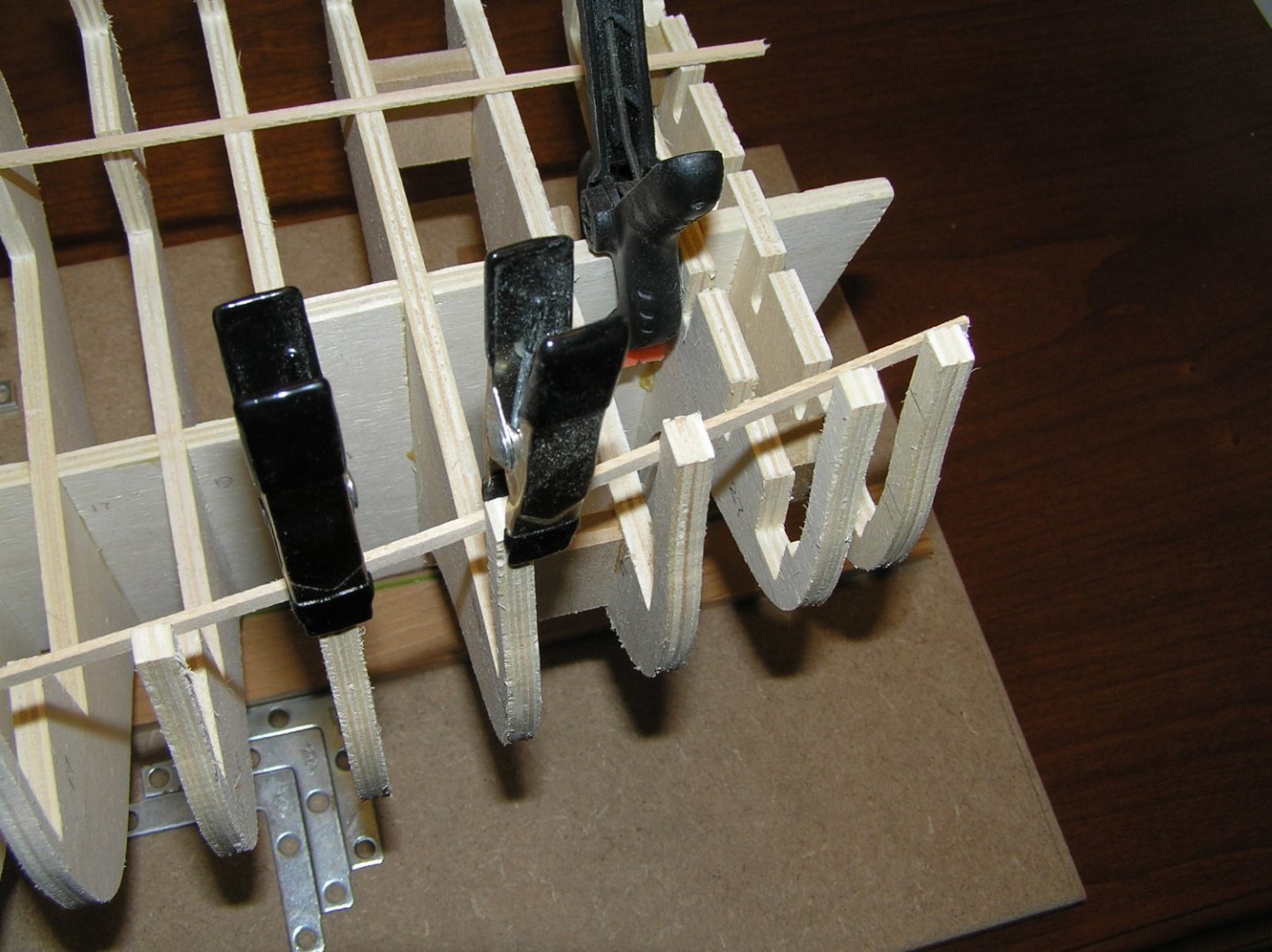
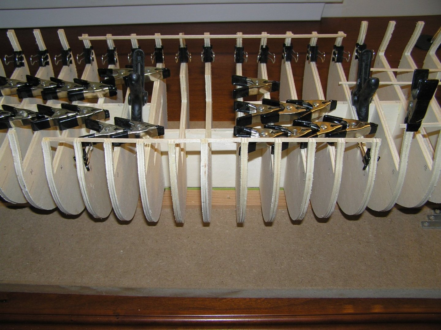
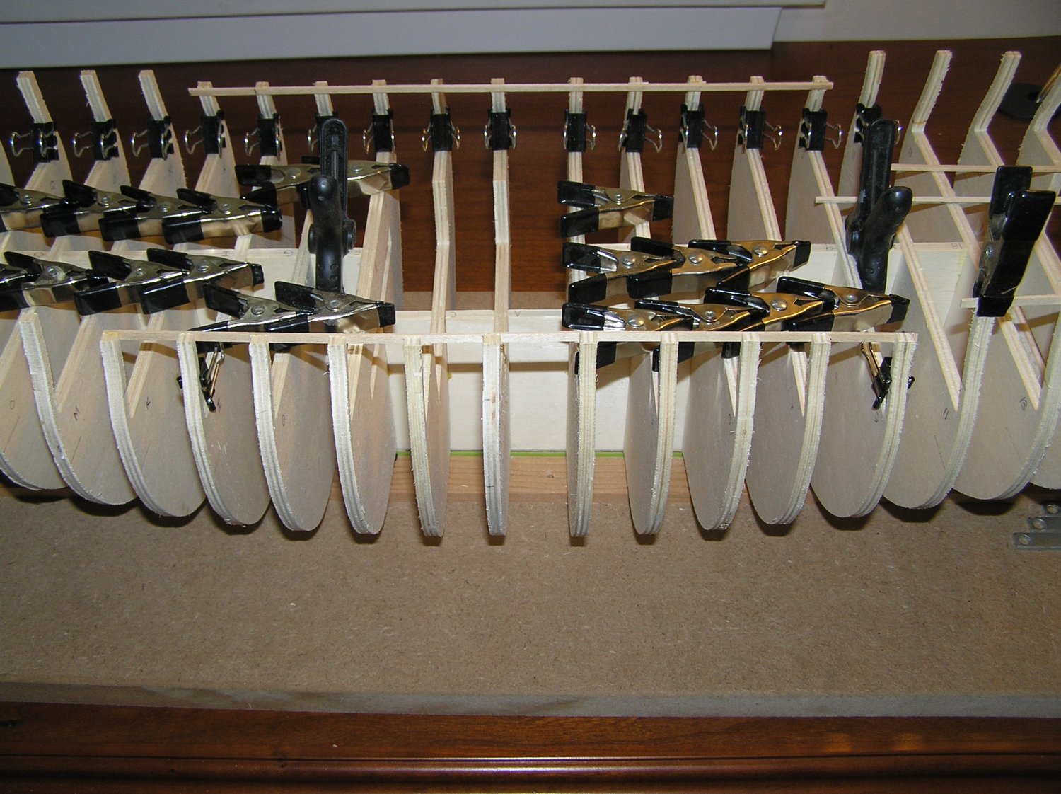
The pressure has finally built to the point where I cannot ignore this model any longer. I took it down to start some of the rudimetary work such as fairing the hull. Although I treated the prior work with respect I did have a number of the mid section uprights crack since last year. I have repaired those but i still find those upper elements quite weak and are sure to break during fairing.
One advantage of a late start is one gets to see how others have worked through their encounters. I hitch hiked on Stunt Flyer's method albeit with my own rendition shown below. I was careful not to force any of the bulkhead uprights out of their rest position as I expected they would spring back when the 1/16 X 1/8 strapping was removed later on. If needed I added a suitable scrap to keep them in their natural position. The end result is a pretty strudy upper frame area that should take sanding well. The bow and stern areas will have to be dealt with in a similar manner but the scrap build out will be a bit more elaborate.
- FrankWouts, Archi, Dave B and 6 others
-
9
-
Dilgence and determination results in a task well done. Just a remarkable beauty Mike! May I ask what are you using to photograph your work?
Joe


HMS Winchelsea 1764 by Thistle17 - 1:48
in Member Build logs for the HMS Winchelsea
Posted · Edited by Thistle17
If at first you fail to succeed try again...and again...and again!
After 2 weeks of on again off again fiddling with the transom framing I think I finally arrived. In no small measure the suggestions and even the "boot in the tail" of the 'master' were the incentives to confront my impediments and move forward. As previously mentioned one key element was the replacement of bulkhead #29. I had adjusted the slots so much of the original ones that I lost the ability for the frames to stay put during construction. So I remade them out of some mahogany that I had gotten from a pattern maker. It took a bit of deliberate hand sawing to get them precise but in the end they proved to be the solution to the loose fit problem of the frames. From that point on it was just a matter of hand tuning the stern upper fillers to get the correct curvature of the stern.
In retrospect the 'boot in the tail' also got me to reflect on my state of mind during the prior attempts. As cautioned so many times before slow and steady is the ingredient needed on this model. But I might add one needs to have the right frame of mind and concentration is a must. I just didn't have it before. I was so frutrated about a week earlier that I even ordered the Chapter 1 kit again in anticipation of starting over. It turned out it was not needed.
While I am at it I would like to comment on the Syren kit. To have the kit manufacturer design, build and create instructions in a progressive manner is not to be taken for granted. When I finished the stern framing construction I pushed back and mused that Chuck must have had me in mind when he produced the kit parts for this section. Who else adds 'spare" parts and template guides as they perceive that some folk will have trouble in this section?
So in the end I think I am where I should be on the transom. I do have some upper counter tuning to do but for the most part it all works. The transom covering piece fits nearly perfect. For me the key was to concentrate on getting the stern port distancing precise.
Joe