SketchupModeller
-
Posts
77 -
Joined
Recent Profile Visitors
1,397 profile views


-
 jchbeiner reacted to a post in a topic:
HMS Pandora (1779) CAD build log
jchbeiner reacted to a post in a topic:
HMS Pandora (1779) CAD build log
-
 Bob Cleek reacted to a post in a topic:
Cleaning Dusty Rigging
Bob Cleek reacted to a post in a topic:
Cleaning Dusty Rigging
-
Keith Black reacted to a post in a topic:
HMS Lizard 1697
-
druxey reacted to a post in a topic:
1/48 ships boat for the Bounty
-
PeteB reacted to a post in a topic:
HMS Pandora (1779) CAD build log
-
PeteB reacted to a post in a topic:
HMS Pandora (1779) CAD build log
-
PeteB reacted to a post in a topic:
HMS Pandora (1779) CAD build log
-
PeteB reacted to a post in a topic:
HMS Pandora (1779) CAD build log
-
PeteB reacted to a post in a topic:
HMS Pandora (1779) CAD build log
-
SketchupModeller reacted to a post in a topic:
Steel's Naval Architecture
-
PeteB reacted to a post in a topic:
HMS Pandora (1779) CAD build log
-
 Syren ship models has 1/64 scale 24, 12, and 6 pdr guns and wooden carriages. Perhaps these might be close to the sizes you need?
 -
Using google image search for "HMS Bounty launch drawing", I found a copy of the plan of Bounty's 23 foot launch on Wikimedia here: http://commons.wikimedia.org/wiki/File:Bounty-launch.png The quality isn't perfect, but it should be usable for a 1/64 or 1/48 model. At a minimum, it's worth looking at.
-
The divisions on the sliding and fixed parts of the caliper are, by design, not spaced identically (this is why your caliper is aligned at 5mm but not at 10mm in the first picture). This is known as a Vernier scale, and allows for precise measurement. Put simply, the human eye can tell, at a very high precision, when two lines are aligned. On a Vernier scale, at any time, there will only be one line on the slide that is aligned with a mark on the fixed part of the caliper. Depending on which lines are aligned, it is possible to read a metric caliper to the nearest 0.02 mm. Here's the best tutorial I could find quickly on how to use a vernier caliper: http://www.technologystudent.com/equip1/vernier3.htm The Wikiipedia page for Vernier scale (http://en.wikipedia.org/wiki/Vernier_scale) is also very good.
-
Druxey - probably not. It is interesting that almost all entries in the 24 pdr column fall very close to quarter-inch increments, and this was the size of gun studied in greatest detail by Robertson. From that I would guess that rounding to the nearest quarter of an inch is probably good enough.
-
In my log of HMS Pandora, I had mentioned that the carriages described in Muller's Treatise of Artillery looked incorrect for a late-18th century ship, and how I had used Harold Hahn's proportions, as provided in an earlier thread in this section. I had also lamented the lack of information about the dimensions of bolts and similar ironwork for carriages. Since then, I have found a primary source on Google Books (link below) that describes the ironwork and corroborates Hahn's proportions. This source can be downloaded as a pdf. Published in 1775, John Robertson's Treatise of such Mathematical Instruments as are usually put into a Portable Case (3rd edition) is primarily a mathematical and geometric text, but it includes the set of proportions of British naval guns, mortars, and carriages for that time. The author states that these proportions were obtained by personally measuring, to an accuracy of a hundredth of an inch, a number of guns then in use. As in Muller's treatise, directions are provided for drawing up a gun using these dimensions. The other useful point found in this work is that Muller's proposals for new guns differ considerably from the British establishment of 1775. The relevant section is Article XX of the Appendix, found on pages 206 to 233 of the book (pages 255 to 282 of the pdf). Page 219 (page 268 of the pdf) is particularly useful, as it gives the dimensions of the various parts of the carriage. Like most books digitized by Google, the plates have not been unfolded for scanning and are almost entirely useless http://books.google.ca/books?id=Ww8Fg5rD8hsC&printsec=frontcover&dq=robertson+treatise+of+mathematical+instruments&hl=en&sa=X&ei=_BPoU-DtFYWjyATihoLgDw&ved=0CCoQ6AEwAQ#v=onepage&q&f=false
-
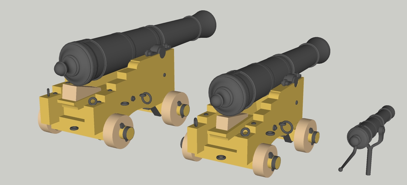
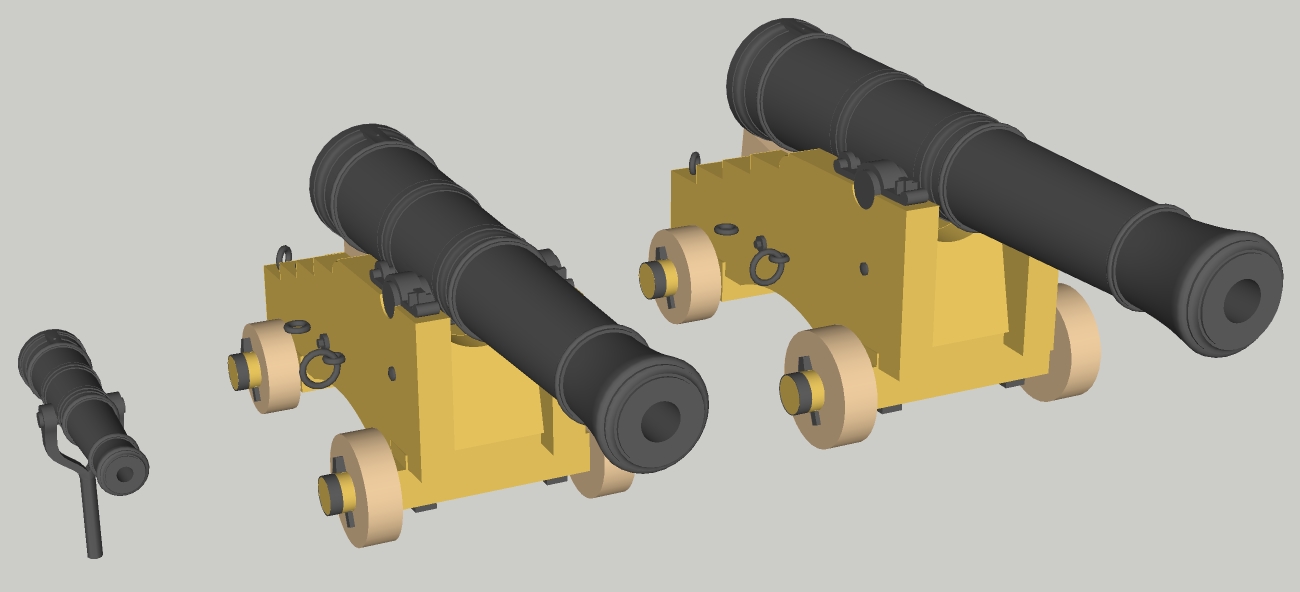
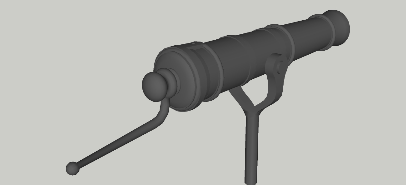
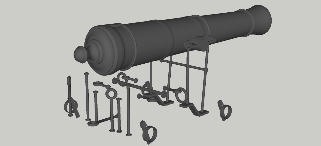
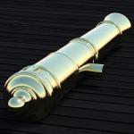
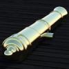
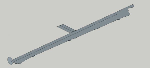
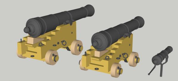
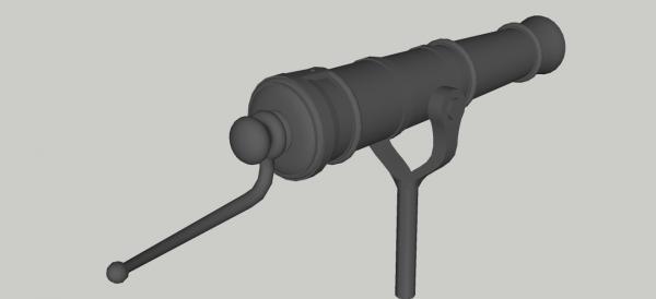
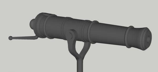
Part 8: Armament As a starting point for the second attempt at this project, I decided to draw up the armament. I will be using the original armament of the Porcupine class, that is 22 x 9 pdr on the gundeck and 2 x 6 pdr on the quarterdeck, instead of the armament of Pandora as sunk (20 x 6 pdr on the gundeck and 4 x 18 pdr carronades on the qurterdeck). This is partly because my model will be of Pandora as originally planned (e.g. Pandora's Box will not be fitted), partly because I have yet to find good references giving the dimensions of carronades, and partly (mostly) because I personally find carronades brutish and unattractive. I have chosen to use 9 pdrs of 7 feet long, and 6 pdrs of 6 feet. The barrels of the 6 and 9 pdrs were drawn using General Armstrong's proportions, as given in the 1768 edition of Muller's Treatise of Artillery. This edition is freely available from Google Books. Detailing, especially around the cascable, was heavily based on a number of photos of period guns. The carriages given in Muller's work seem date from the middle of the 18th century, and look to be a bit too long for the end of the century. Instead, I used Harold Hahn's dimensions as fournd in this thread http://modelshipworld.com/index.php/topic/6059-making-gun-carriages/, which look much better (to my eye), and seem reliable, as the dimensions of the barrels match up well with Muller's work. As an example, the 9 pdr carriage should be 63 inches long as per Muller, but only 50 inches long as per Hahn. The quoins and carriage ironwork (shown below) are only approximations, as I have not been able to find any definitive references for these parts. The 1/2 pdr swivel was taken directly from the plans given in McKay's AotS Pandora, with a number of photos again used as references. In all cases, the barrels were drawn first as a half profile, which was then rotated into a complete barrel using the 'Follow Me' tool and a circle at the muzzle end. The touchhole and trunions were then added. The last picture shows one of these profiles, with the position of the trunions marked out and the vertical circle for forming the 3D barrel.


-
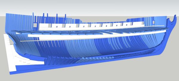
Part 7: Starting Over For the past few months, I have been working ahead at skinning over the surface and cutting out frames, and starting on the gun deck beams and framing. As shown below, this is considerably farther ahead than the previous entry here. However, a few recent developments have made me decide to terminate work on that version and start over. First, further research showed a number of significant errors. Most importantly, I had assumed that the frames were square to the load waterline, and drawn them in as such. Reading through the Shipwright's Vade-Mecum, and watching other logs. I learned that the frames should be square to the keel. This means that the shape of the body as drawn is incorrect. Next, I purchased a copy of Scantlings of the Royal Navy, which showed that a number of my measurements were woefully inaccurate (for example, the drafted keel was sided 4 inches too large, and the toptimbers were sided 3 inches too small). My next attempt will be heavily based on the dimensions given in the Scantlings book. At about the same time, I made a decision that the CAD model would (eventually) be used as a basis for a POF model. For this, I would need to increase the resolution of the hull (the previous version, while smooth enough for computer rendering, would not be adequate for use as a pattern, and certainly not at a scale of 1:48 or larger). Finally, I would like to ask any member with a copy of Steel's Naval Architecture or the Shipwrights Repository if they would be able to PM me a copy of the table of the body of the 24 gun frigate, as having that information would greatly help to accurately form the shape of the hull.
-
Don - I'm still using Sketchup 8. From Sketchup 2013, a new system of plugins, the Extension Warehouse, was introduced. This is probably where the problem you're having originated. Two articles from the Sketchup site that discuss adding plugins/extensions to Sketchup 2013 and 2014 via the Extension Warehouse and manually installing .rb files are here: http://help.sketchup.com/en/article/38583 and http://help.sketchup.com/en/article/3000050. Hopefully this will help.
-
I also don't see a problem. You have correctly cut the frames to match the pattern. When installed, the frames will be angled to sit against the ends of the transoms. When angled like this, the top ends of the frames will be closer together than they originally appear on the pattern (I think this is your main concern, please correct me if it isn't). Consider it this way: lay a book open on a table, then watch how the distance between the corners decreases as you close the book. The pattern is printed as if the 'book' were wide open, so that you cut the frame to the correct shape, and during installation the 'book' is partially closed. Hopefully this helps explain why your spacer block fits with the frames on the pattern and not with the frames installed.
-
Hello Chris, it's always good to see another CAD project around here. I agree with Russ's comment that frame timbers would be shifted to fit the ports. Also, the Hahn style of building includes a significant simplification that would interfere with frames lining up with gunports. Hahn made his frames the same thickness for their whole length, while in real life the frames would be thicker at the keel and reducing in thickness (in the fore and aft direction) towards their upper ends. For example, a frame might have been 1'-3" at the keel and reduced to 1' or less at the topsides. As a result, even if frames did not have to be shifted, it is unlikely that gunports that did lie between frames in real life would correctly lie between Hahn's frames. Because of this, I would not automatically ascribe differences between the sides of the gunports and frames, especially Hahn method frames, to inaccuracy in the original drawings. A better check for accuracy might be to compare the distance between each pair of gunports - this should be the same for every pair (although some might be different to fit around entry steps, etc.) Hopefully this will help.
-
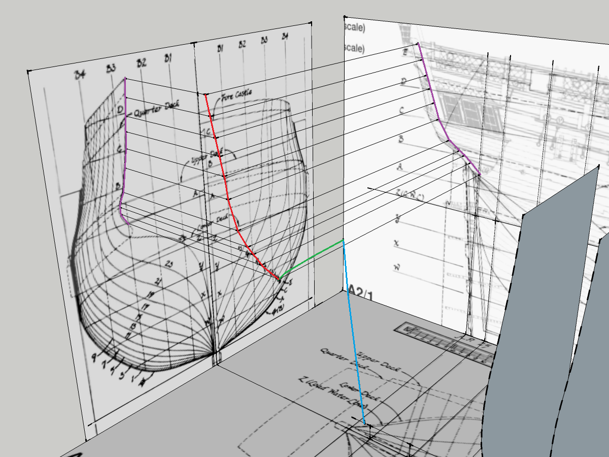
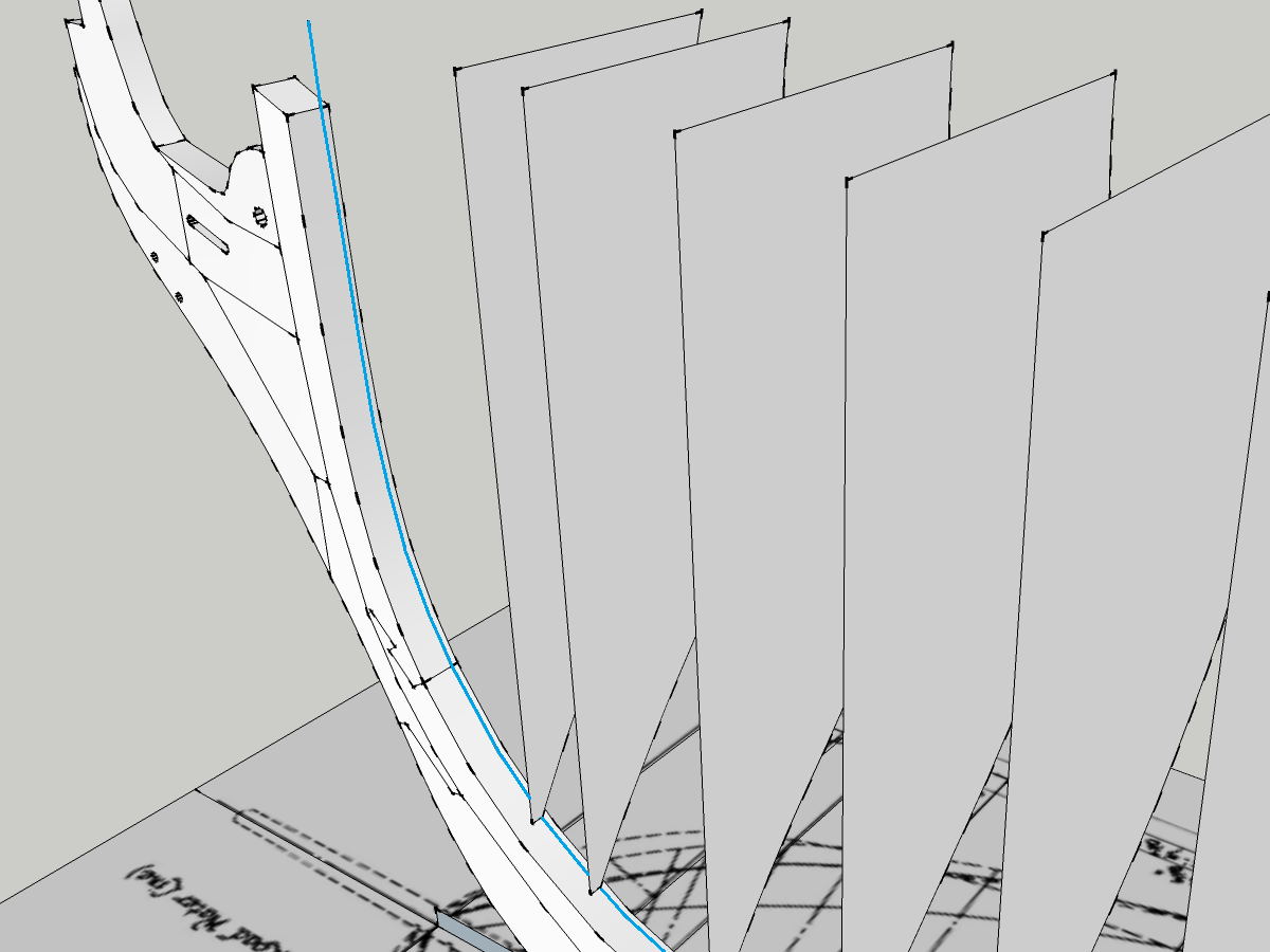
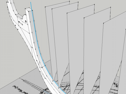
Part 6: Getting ready to form the hull After a bit of a delay, I'm back. Back on page 2 (and almost a year ago!), the stations were defined. The stern needs to be defined, and the bow and topsides still need a little work before the surface can be skinned. These will be the subjects of today's post. The edges of the transom, counter, and stern timbers were drawn in by tracing these timbers from both the body and sheer plans (purple lines) and projecting to an intersection, as shown below. The final edge is highlighted in red. The aft edge of the wing transom (green line) was traced from the framing plan, and the blue line follows the rabbet on the sternpost. Note that the last few stations have been hidden for clarity. Next, lines were drawn in to define both the lower and upper edges of the hull's shape. The lower edge is simplest, as it merely connects the bottom ends of the station lines. Forward of the foremost station, this line continues up the stem, so that it defines the profile of the hull as seen on the sheer plan. Later, this line will be used to form the rabbet. The point at which this line terminates is taken from the sheer plan. Only the forward portion is shown below, but this line (blue) continues all the way aft. Most of the upper edge was drawn in using the same method of connecting station to station and tracing from the sheer plan when needed (for example, at the scrolls). Finally, a curve was drawn in to connect the first few stations and the forward line described above. For this, I tried a number of different splines and curves included in the BezierSpline plugin until I found one that looked reasonable. The end result of all of this was the construction of a number of closed loops that together will make up the surface of the hull. The next post will discuss how to create this surface.

-
FYI, Nigel, £42.50 is closer to $80 Canadian. Still, a very fair price for that book.
-
While I don't know what the rules are for serving, I can recommend a few books that might be helpful. The first two works I would suggest are The Masting and Rigging of English Ships of War 1625-1860, by James Lees and David Steel's Elements of Mastmaking, Sailmaking and Rigging (also published as The Elements and Practice of Rigging and Seamanship). Steel's work was originally written around 1794, and describes the British practices of the time. His book is freely available online here: http://hnsa.org/doc/steel/index.htm. Admittedly, much of his language can be difficult to comprehend, but I would say it is one of the most useful. Notably, he lists the size and length of every spar, rope and line for all ships, from a cutter to a first-rate Lees's work is not freely available, but was written with the modeller, not the shipwright, in mind, and provides a comparative description of rigging at different times. His work is well illustrated, and provides some information as to the correct sizes of parts, but not as detailed as Steel's. After these works, Lennarth Petersson's Rigging Period Ship Models is helpful, as it shows where every rope is supposed to go, and can be a quick way to identify the components described in more detail by the first two works. However, he does not include any written description, and this work only describes a frigate of around 1800 (but could be applied, with caution and referring to the previous two works, to other ships of a similar timeframe). Hopefully this at least gives you some suggestions for where to start looking, and I'm sure someone else will come along and provide an answer.
-
I've used a clean, EMPTY airbrush before on plastic kits. It seems to work reasonably well and is more controllable and gentler than the compressed air used to clean computers. Start at a low pressure and work up to the highest pressure you feel is safe.
-
Keep in mind that there tends to be "scale creep" in at least some ranges of gaming figures (the figure is larger than the advertised scale e.g. a figure advertised at 28mm actually measures 30mm tall), so some 25mm figures might be more correct size-wise than 28's.