Kirby
-
Posts
35 -
Joined
-
Last visited


-
 Kirby reacted to a post in a topic:
Sultana by DanB - Model Shipways - 1:64
Kirby reacted to a post in a topic:
Sultana by DanB - Model Shipways - 1:64
-
Kirby reacted to a post in a topic:
Sultana by DanB - Model Shipways - 1:64
-
Kirby reacted to a post in a topic:
Sultana by DanB - Model Shipways - 1:64
-
Kirby reacted to a post in a topic:
Sultana by DanB - Model Shipways - 1:64
-
Kirby reacted to a post in a topic:
Constitution by Geoff Matson - Model Shipways 2040 - 1/76 scale
-
Kirby reacted to a post in a topic:
Sultana by DanB - Model Shipways - 1:64
-
Kirby reacted to a post in a topic:
Constitution by Geoff Matson - Model Shipways 2040 - 1/76 scale
-
Kirby reacted to a post in a topic:
USS Constitution by usedtosail - FINISHED - Model Shipways - scale 1/76
-
Kirby reacted to a post in a topic:
Sultana by DanB - Model Shipways - 1:64
-
Kirby reacted to a post in a topic:
USS Constitution by JSGerson - Model Shipways Kit No. MS2040
-
GrandpaPhil reacted to a post in a topic:
USS Constitution by Kirby Francis - Half-hull - Scale 1:192 From AJ Fisher Plans
-
mtaylor reacted to a post in a topic:
USS Constitution by Kirby Francis - Half-hull - Scale 1:192 From AJ Fisher Plans
-
 Hi Tim! Great to hear from you, and looking forward to getting together with everyone when the plague has finished its rounds. Thanks for the offer - any info is helpful, and multiple angles are always good to see. One of the interesting problems with this model is that there is so much information out there. I'm going with the Fisher plans for the most part, even though they are only one snapshot of the ship. Roger's point above is a good one - the lines don't match the configuration she has now, when we sailed on her a few years ago for the turnaround cruise. Thankfully, as a half-hull representation, I do feel that I can take a certain amount of license. I also am less committed because I don't have to choose a rig, or gunport locations, etc, etc. At this scale, I'm going to get close to her real lines, but not get them completely on. I'm getting to a point now where faring the hull would require certain stations to be off of the plans, anyway.
 -
mtaylor reacted to a post in a topic:
USS Constitution by Kirby Francis - Half-hull - Scale 1:192 From AJ Fisher Plans
-
Thanks, Jaager. It really is a challenging scale for this model, at least for me. There's a reason I'm using Douglas Fir, even though it's not the optimal for this purpose. I have found that Cherry, Maple, and Mahogany are all well suited to carving half-hulls, provided the piece is free of defects, and your glued-up blank has grain lines running in the same direction. Thanks for the recommended links! I will definitely check those out.
-
Siggi52 reacted to a post in a topic:
USS Constitution by Kirby Francis - Half-hull - Scale 1:192 From AJ Fisher Plans
-
mtaylor reacted to a post in a topic:
USS Constitution by Kirby Francis - Half-hull - Scale 1:192 From AJ Fisher Plans
-
Roger Pellett reacted to a post in a topic:
USS Constitution by Kirby Francis - Half-hull - Scale 1:192 From AJ Fisher Plans
-
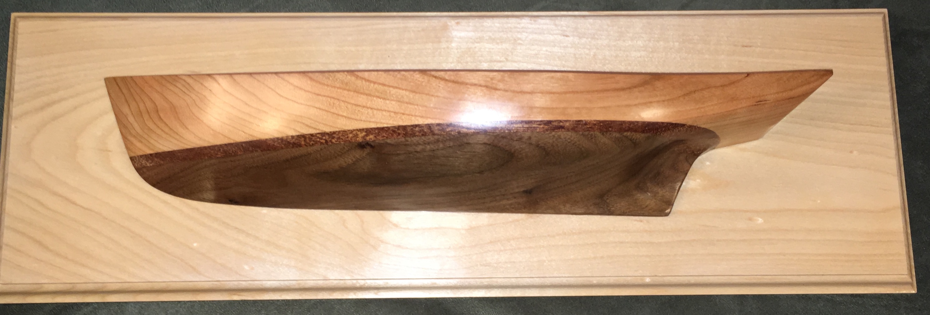
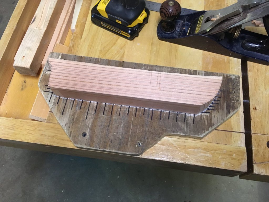
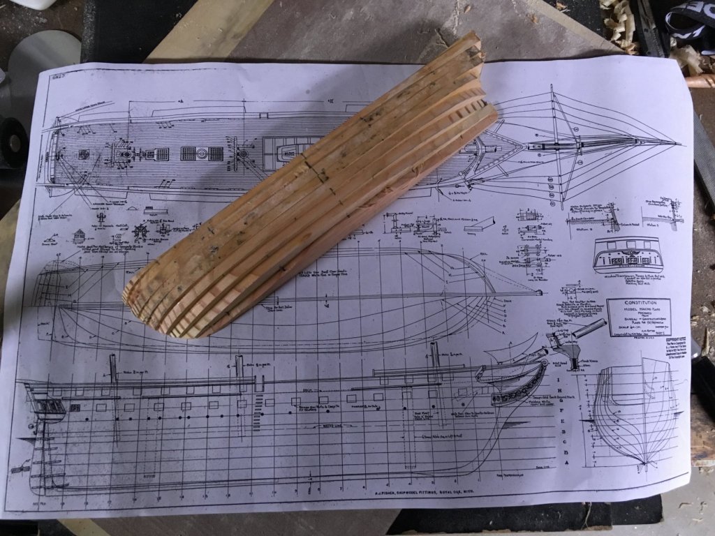
Well, it's certainly been a while on this one. So long, in fact, that I think I made significant (and unreported) progress on the new, solid hull blank. I put it away about a year and a half ago, when my business really started taking off. Surfaced this the other day while reorganizing the workshop: It's pretty close to the dimensions it should be. Which leaves me to reconsider my plan for the keel, sternpost, and rudder post strips underneath her. I have decided not to do the railing details on top. Leaning in to the historicity of half-hulls as builder's tools, the ornamentation isn't really necessarily, and may actually distract. Certainly open to suggestions on this!

-
popeye the sailor reacted to a post in a topic:
USS Constitution by usedtosail - FINISHED - Model Shipways - scale 1/76
-
Will be keeping you in prayer, Jon. Look forward to your speedy recovery!
-
You could also try tinfoil underneath the model - that way you can hear the "ping" as it drops.
-
CaptainSteve reacted to a post in a topic:
USS Constitution by Kirby Francis - Half-hull - Scale 1:192 From AJ Fisher Plans
-
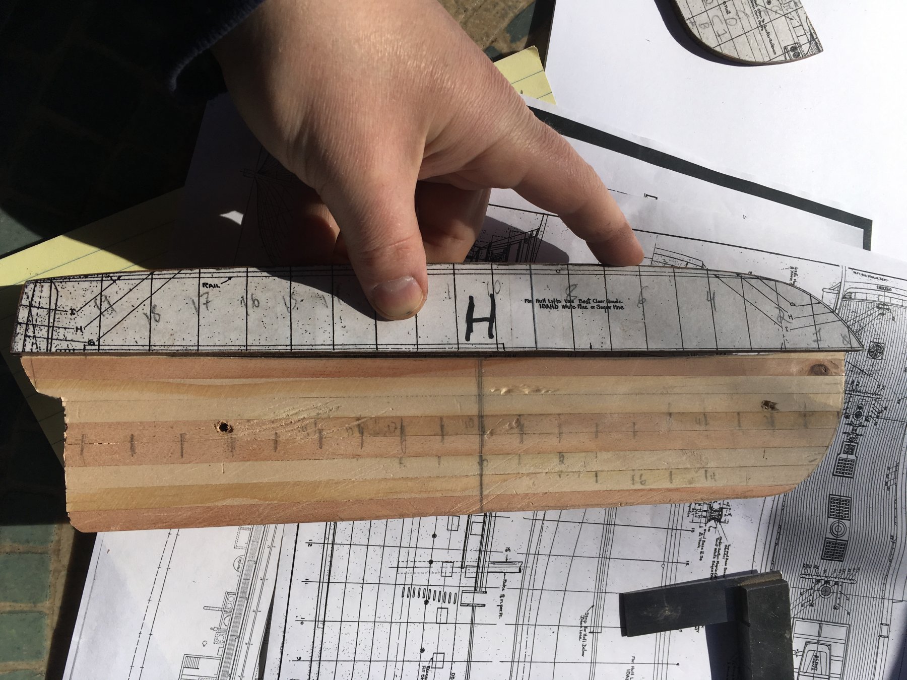
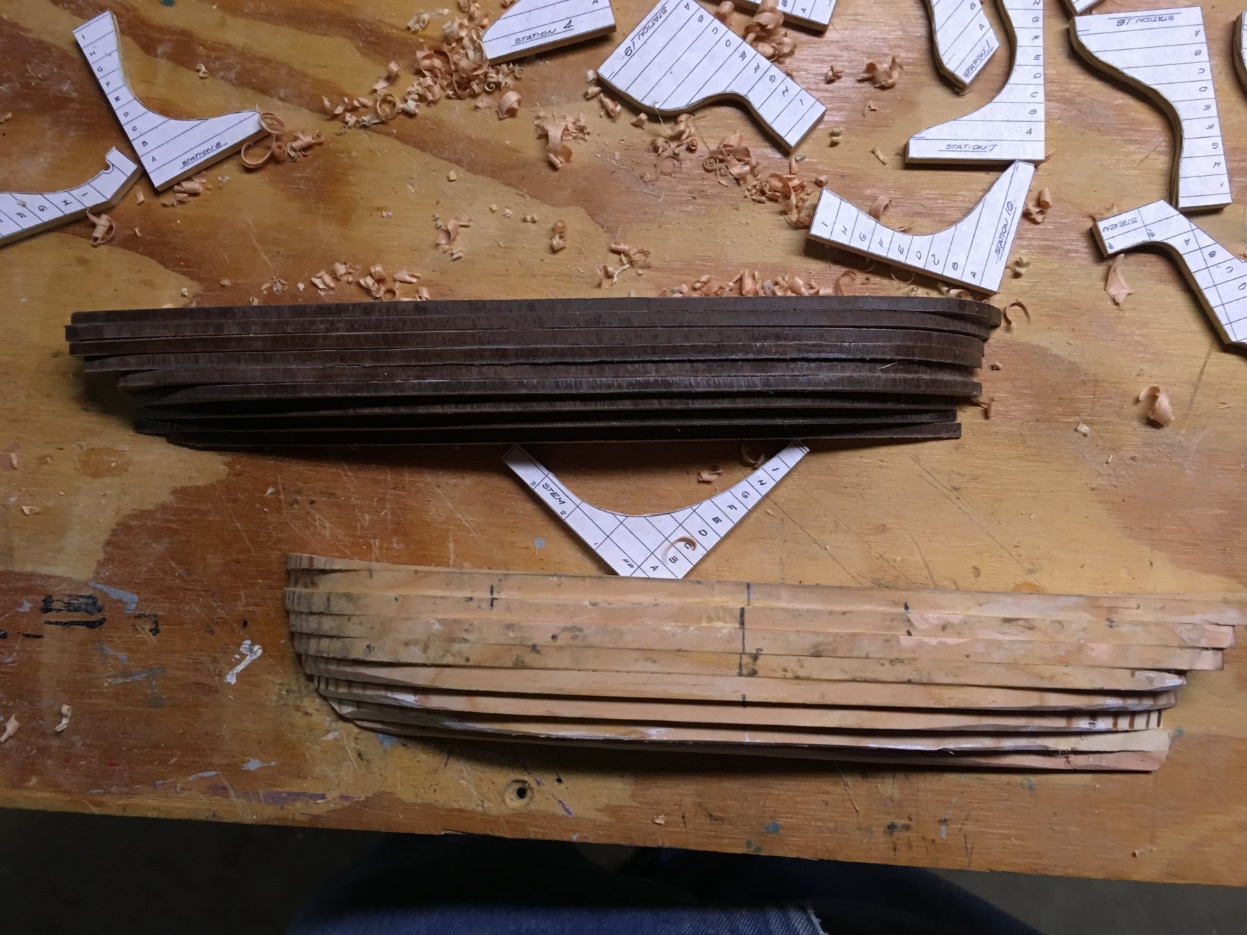
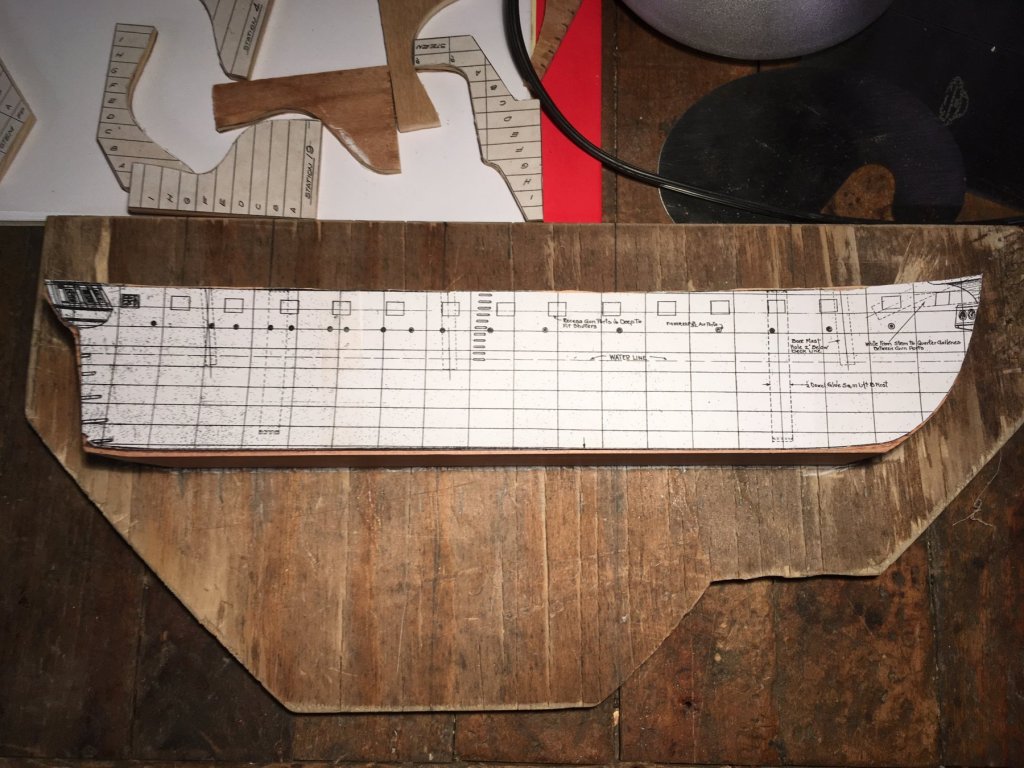
If at first you don't succeed as a wooden model shipbuilder.... at least your efforts are combustible. And there's something to this idea of learning from failure. As it turns out, the Harvard Business Review once published some great articles on that subject. I had some time on Saturday, so I sat down with the AJ Fisher plans, the Chapelle plans, and a very strong cup of coffee. What I realized, after carefully checking the hull to the plans, is that I had taken off far, far too much material in the transom area. You can see this when I compare the hull to the second to top lift, "H". What happened? Well, as the article referenced above puts it, there was an entire "Spectrum of Reasons for Failure". To be charitable, there are few half-hulls of Old Ironsides out there, and most seem to be built with some kind of moulded hull, or plank on frame. On the other side, I'm also an inexperienced ship modeler, so some of my cuts have gone awry, and too much material was trimmed off both fore and aft, even as the relative contour was kept. I have heard many experienced model makers talk about that point where they knew they needed to abandon an attempt, and start over. This first, lift-based attempt may not go in the furnace just yet, but it is going to be set aside. I am going to start over with a solid block - a carving situation with which I'm more familiar from the other half-hulls I have made. Here is the block mounted, with a carefully rendered hull copy, from the plans. Note that I actually have her bow pointing the right way this time. We're already doing better. As HBR puts it, "A process composed of many elements breaks down when it encounters novel interactions". Put another way, there are enough "novel interactions" in this build for me as it is. The lifts ended up being 1/32 off by lift "D", and then 3/32" off by lift "H", making things harder to align with the carving templates. This time, the lift and station lines were precisely scribed to the mounting board, and I can have a more true reference while removing material. One of the comforting elements of that HBR article for me is the suggestion that we ought to own the correct responsibility vis-à-vis failure. It is not our responsibility to never fail. It is our responsibility to surface, admit, and analyze failure. I'm not saying that I will never return to the lift method for this, but for now, I am going to restart with a clearer sense of how to keep the correct length for the hull, and hopefully minimize unnecessary complexity. And, I have a spare hull now to experiment on with various looks for chain plates, trailboards, etc. Back to the chisels, gouges and planes!

-
You nailed the colouring and proportions to a “T”! Glad the trip was enjoyable, and I’m sure it’s more enjoyable to sail when there’s no incoming fire from shore.
-
Thank you! Yes, the thickness sander built for instrument tops, backs and sides works well on wood for scale models, too. As does the feeling of being completely out of our depth at many stages of a project. My biggest gripe with the Fir is that even finer tools tend to rip out wood between the annular growth. The difference in density between the rings and softer wood between makes it tough to work with cutting tools. With it being painted, I think poplar would be a good choice, but for some other constraints that require Fir for this one.
-
Thanks, Rob! I appreciate your insight. While I hope to keep her hull as close to the plans as possible, having some ornamentation like chain plates, deadeyes, trailboards, quarter galleries, etc, might make up what she'll be lacking in perfect lines.
-
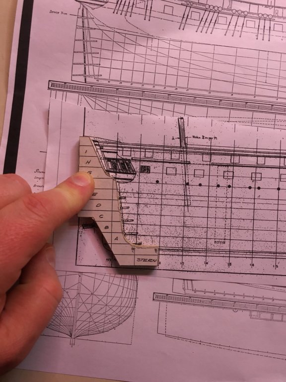
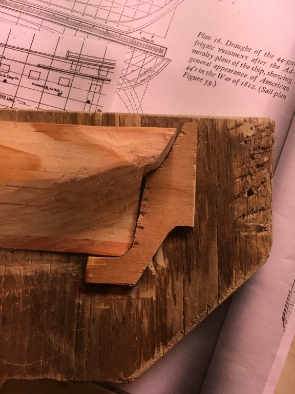
A friend at the ship club resized Chapelle's plans for the President to 1/192 for me, and the reference information is valuable in adding details to the AJ Fisher plans. At times, they disagree. For instance, I am currently working on the profile of the half-hull at the stern. Notice on the Fisher plans that the hull line which meets the sternpost actually arcs towards the keel, whereas it is straight on Chapelle's. Differences like this help me make more conscious decisions. Little by little, I'm finding that the reams of information on this ship can be used to clarify choices, instead of paralyzing me as a modeler from making them.
-
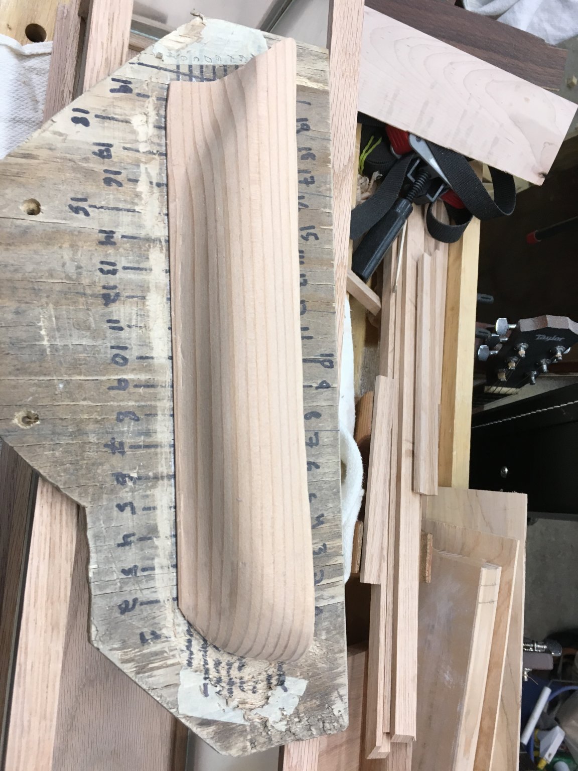
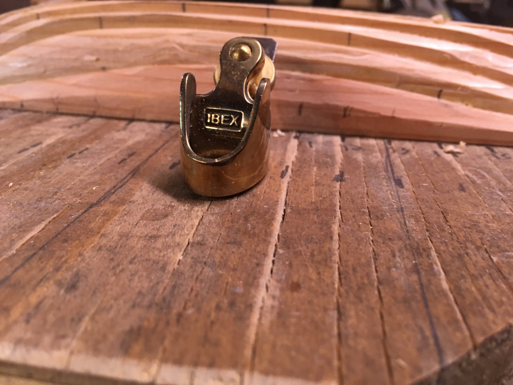
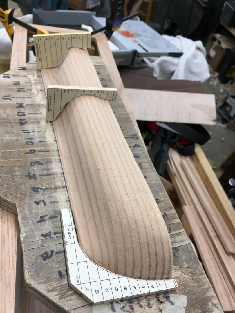
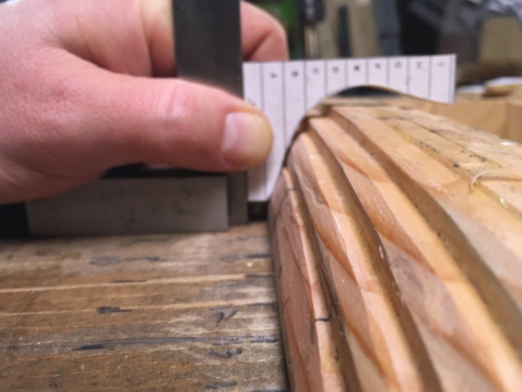
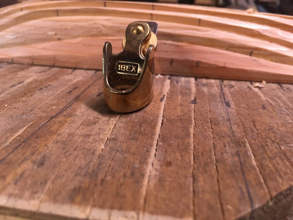
After some preliminary carving, it was time to mount the model to a temporary backboard. This allows me to secure it in a vise for carving, and carve right down to the rabbet line, etc. Good 'ole 3/4" plywood fits the bill nicely. I sanded it flat so the half-hull will sit on it in the same way as the intended mounting board. On the backboard, I can use a square to make sure my templates are hitting the hull parallel. By aligning them with the right lift, I can ease them down until they make contact. Then it's the same process as described above: mark with a chalk pencil, and carve. I'm finding that for some areas, my finger plane (which has a concave sole and blade) is helping. Otherwise, it's 3/8" and 1/4" gouges, and occasionally chisels and card scrapers to even out the mess.
-
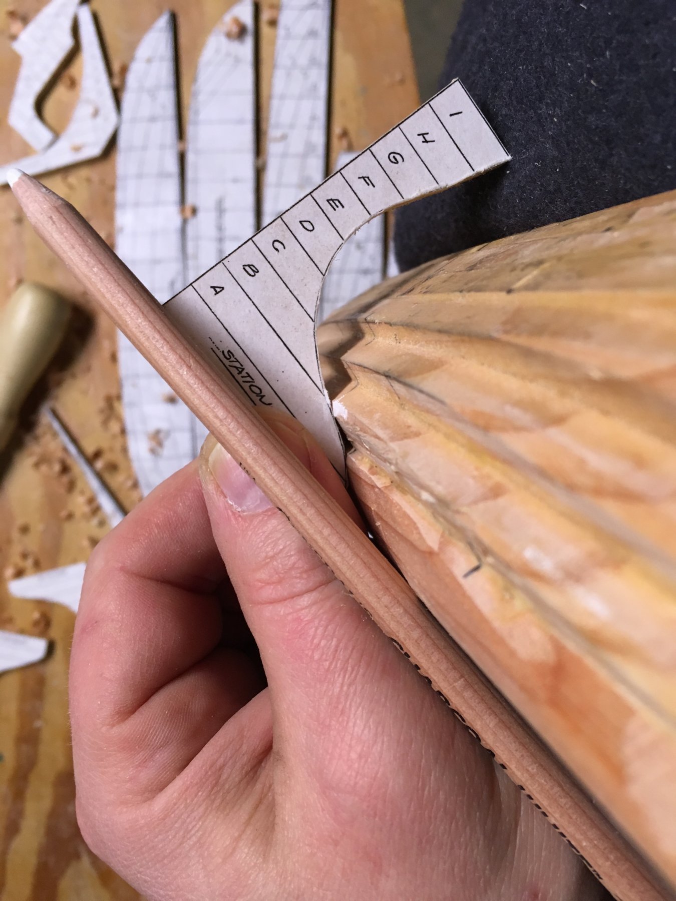
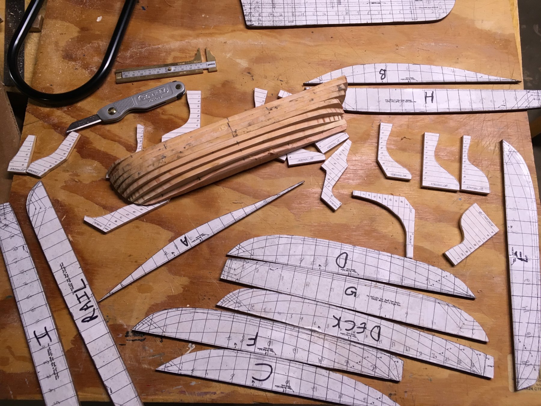
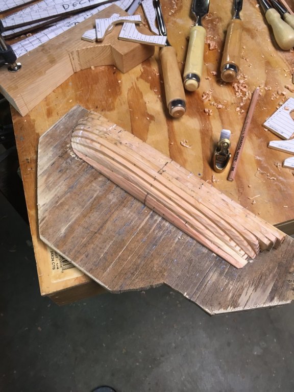
Carving the Hull On the three previous half-hulls I have made, I have essentially glued up blocks of material. I use a bandsaw to cut the sheer, the outline as seen from the top, and side profile of the hull, and then hog out the mass of material until it gets close to the station lines. There is far less mass of material to move here. And what is there to remove seems to love splintering under the chisels and gouges. There's a reason not many models are made from Douglas Fir, it appears. To carve, I hold the template up to the side of the hull at the correct station line (station lines are on the back, or flat side of the hull, and pulled around to the deck on top as well). I then use a chalk pencil to highlight which lift needs material removed. I run up and down the stations of the hull with these marks, then carve a bit. As the template touches more lifts, more get marked to have a bit of material removed.

-
Gluing Up the Lifts Using the station lines from the lift templates, I transferred station line numbers to the sides of the wooden stock as I traced the lift outlines to each one. Lifts are lettered A-I on these plans. The astute observer will note that this novice has already made his first serious mistake - the stern of the ship was meant to the on the left side of the mounting board, as per this page of the plans. Ooops. For the next one, I can reverse the lifts to orient it correctly, as you see below. Also, I was not satisfied with the fit of lift "C" - the stern side of it has too little material, which may be due to movement during glue-up, or an incorrectly numbered station line on the back of lift.

-
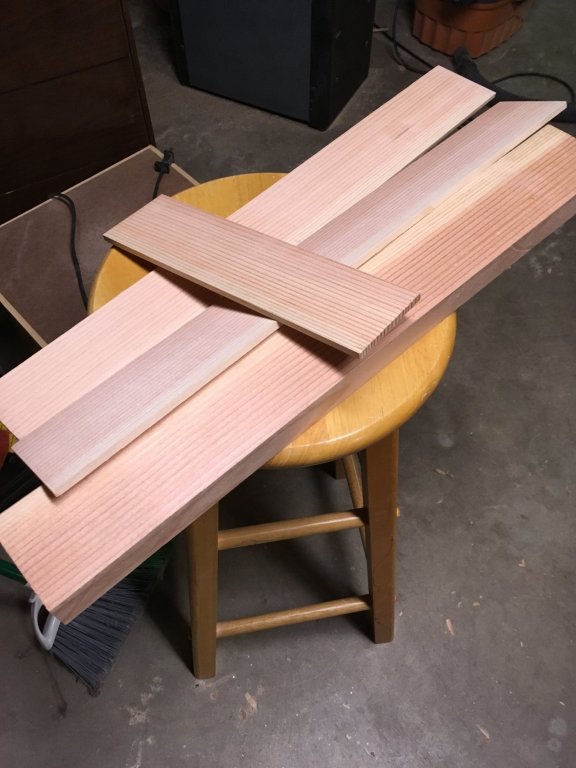
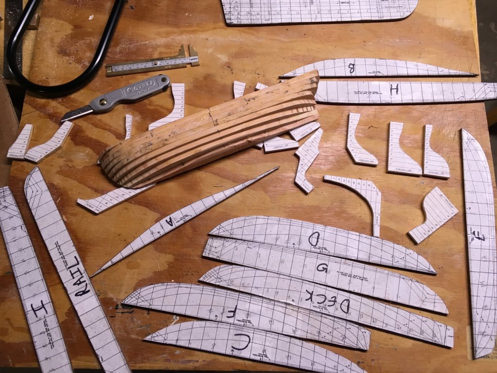
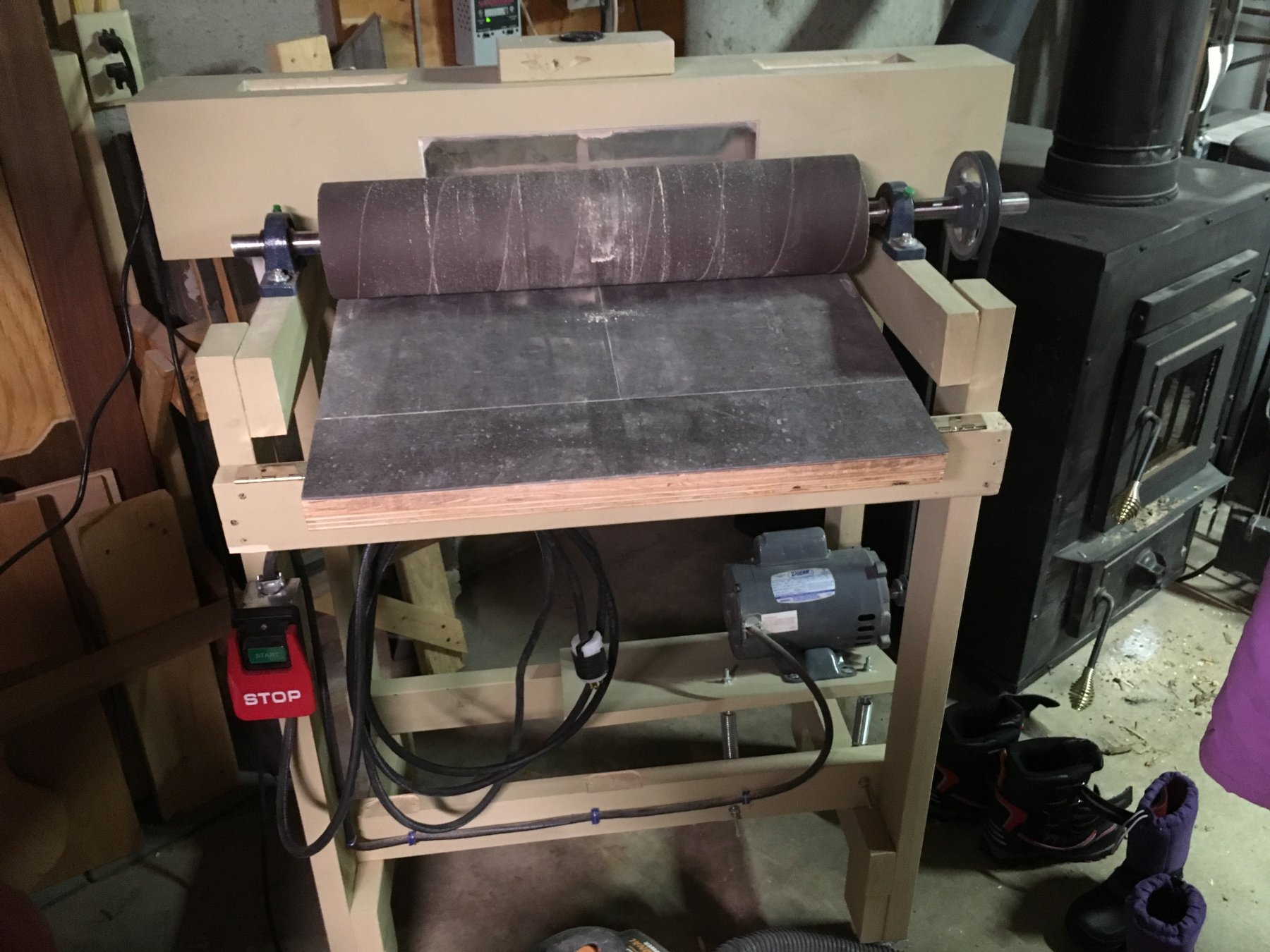
Stock Preparation and Templates Having decided to use a lift method of construction, I reduced the Douglas Fir 2x6 (left over from building a picnic table, in fact) to 1/4" planks. This was accomplished using a resaw blade in the bandsaw, and then a shop-made thickness sander. In the picture, the thickness sander dust cover sits behind the roller. With the main stock for the ship prepared, I glued cutouts of the station and lift templates, from the plans, to some scrap 1/4" plywood, and MDF I had in the shop. I went over both heavily with some spray poly, to keep the MDF especially from furring over time. The plans were cut out at the bandsaw, and tidied up on the disc sander, and with a shop-made Dremel "router table", with a sanding attachment in the Dremel. With the stock and templates ready, it was time to align, and glue up some lifts.