Timbers_B_Shiverin
-
Posts
8 -
Joined
-
Last visited
Content Type
Profiles
Forums
Gallery
Events
Everything posted by Timbers_B_Shiverin
-
 Although I haven't worked on it in a long time, I also did some work on adding lighting to my Syren. Very similar to you, I will be using pico LEDs, but I am still not sure where. Definitely below deck and maybe a couple other locations. It will be great to see how you place them. I also did some work on a small lantern:
 -
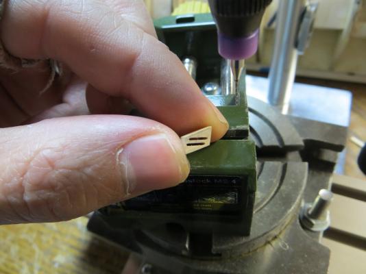
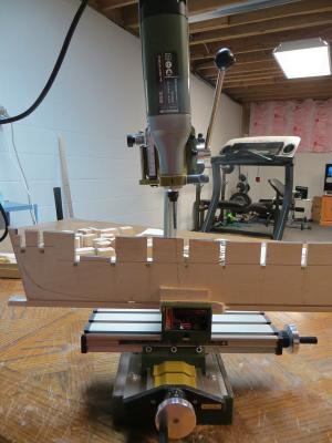
Hi Hervie, Welcome to MSW. I am enjoying your Syren build, as I am also (slowly) building one. Regarding the masts, I was also wondering when the holes should be drilled. This is my first build, so I have no experience. I decided to drill them while it was still easy to mount the model in my drill press. See post #5 in the build log below for what I did. http://modelshipworld.com/index.php/topic/9886-us-syren-by-timbers-b-shiverin-model-shipways-scale-1-64-first-wooden-ship-build/ Hope that helps. -Brian
-
Hello everyone. It's been a while since I have posted. My Syren has been build has been put on hold because I heard the call of another "syren", which I will start a build log for soon. Thought I would share some pics of where she stands for now. Towards the end of summer, I finished the treenailing the upper planking and applied a single coat of WBPU to the port side. The starboard is still un-planked at this point. Started by lining/marking the treenail locations I drilled to holes using a #70 bit, and then lightly touched the hole with a pencil to simulate a caulk line. The hole was then filled with Elmers "Golden Oak" wood filler, which seems to be a pretty good match with the castillo boxwood used for the planks. Then everything was sanded down and a coat of water based polyurethane was applied. I am pretty happy with the results for a first-timer. Where she stands now, on the shelf for a little while...


- 17 replies
-
- 9
-

-
- syren
- model shipways
- (and 1 more)
-
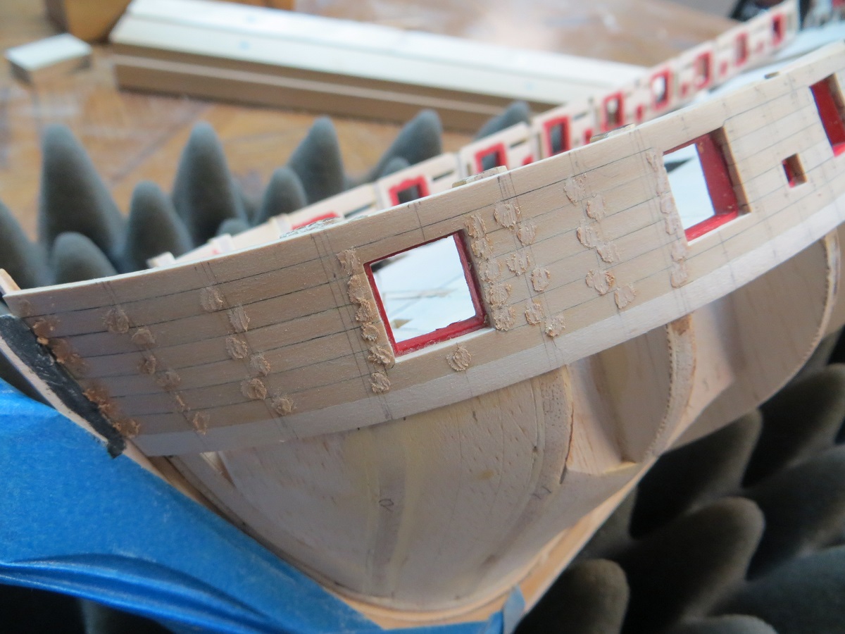
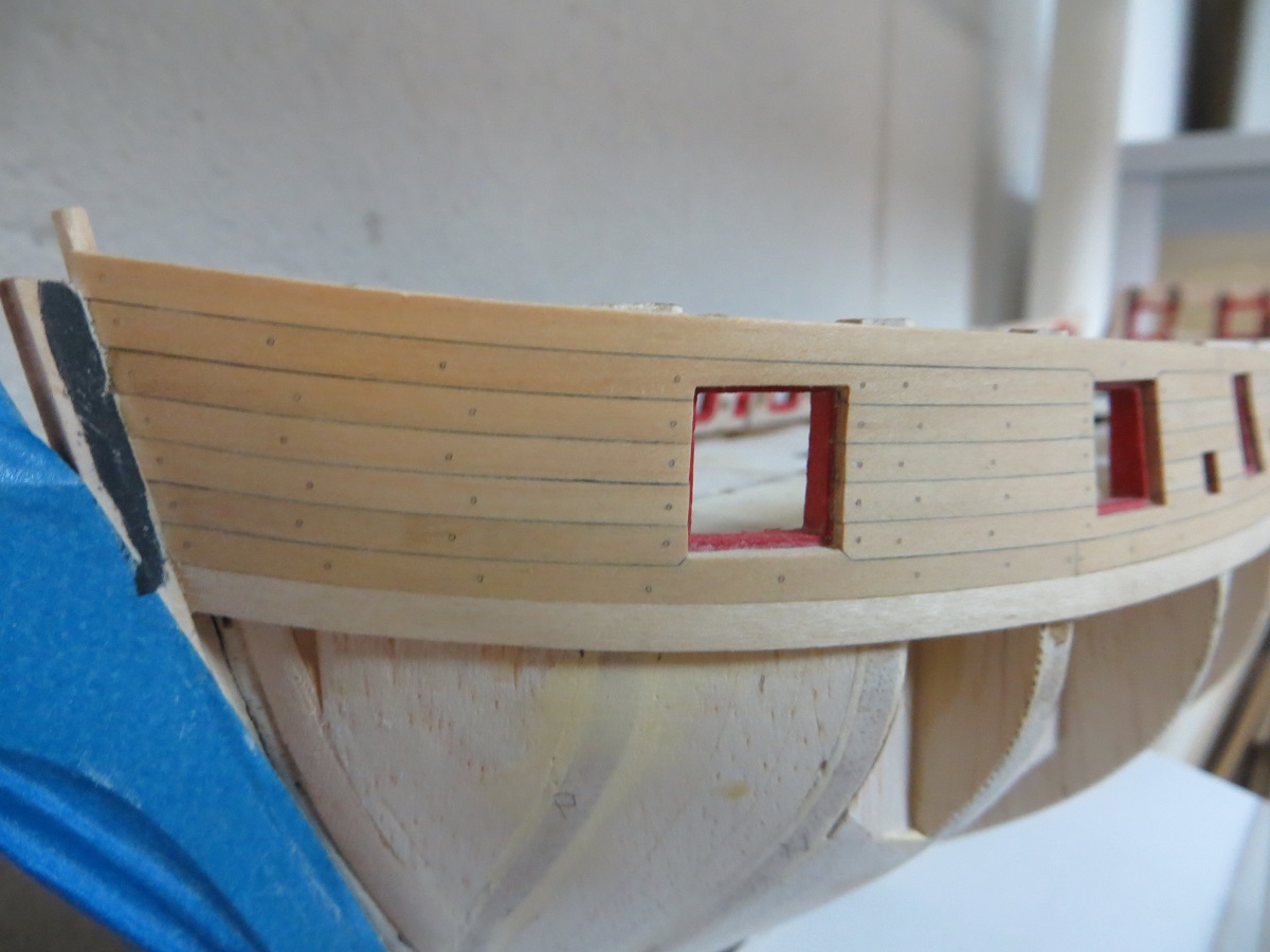
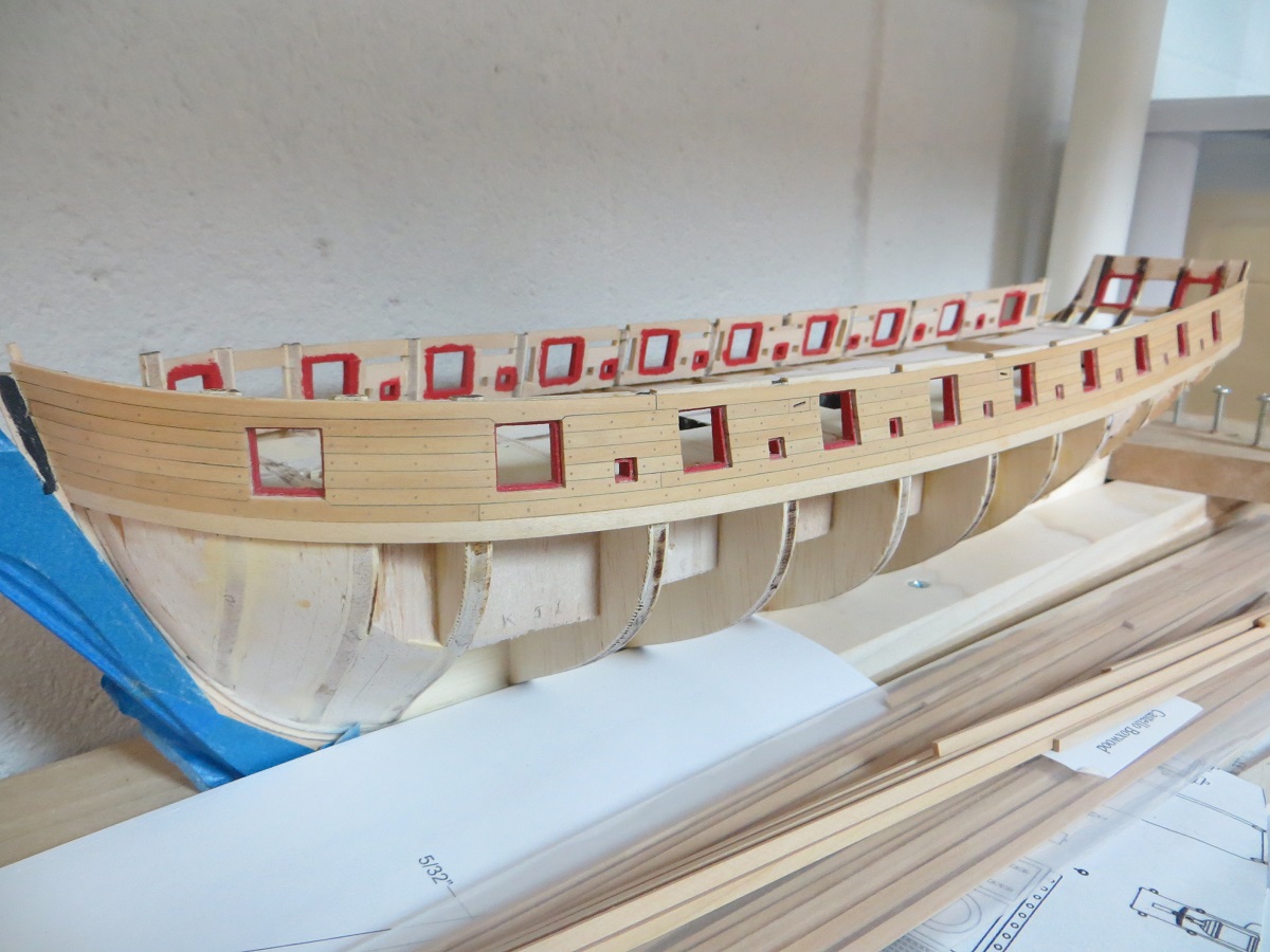
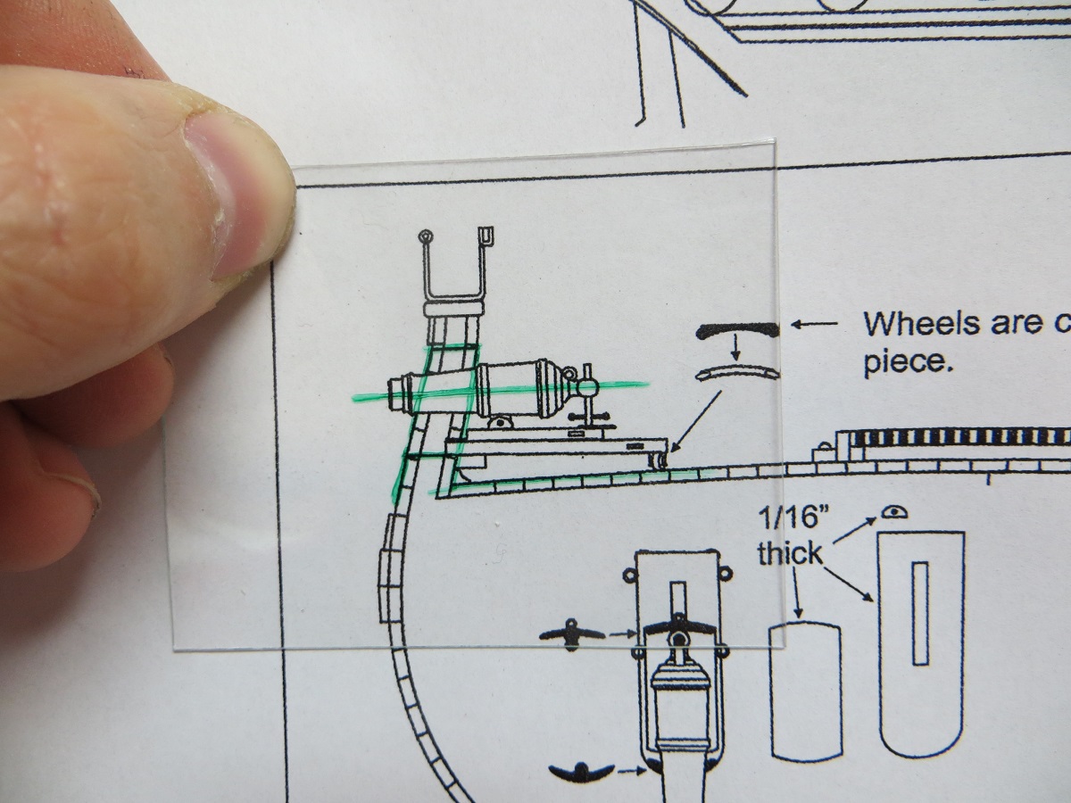
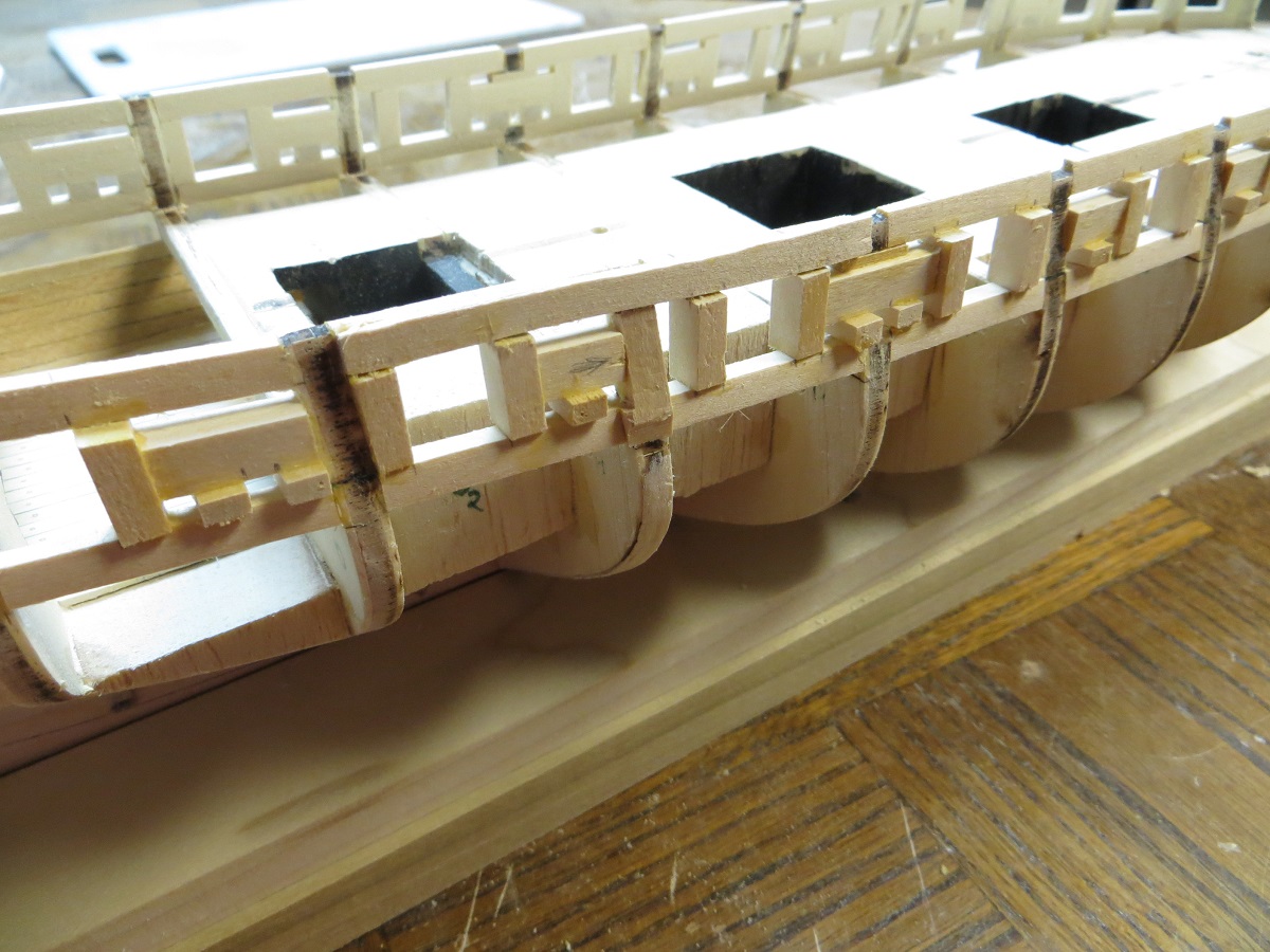
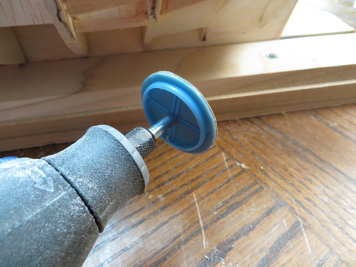
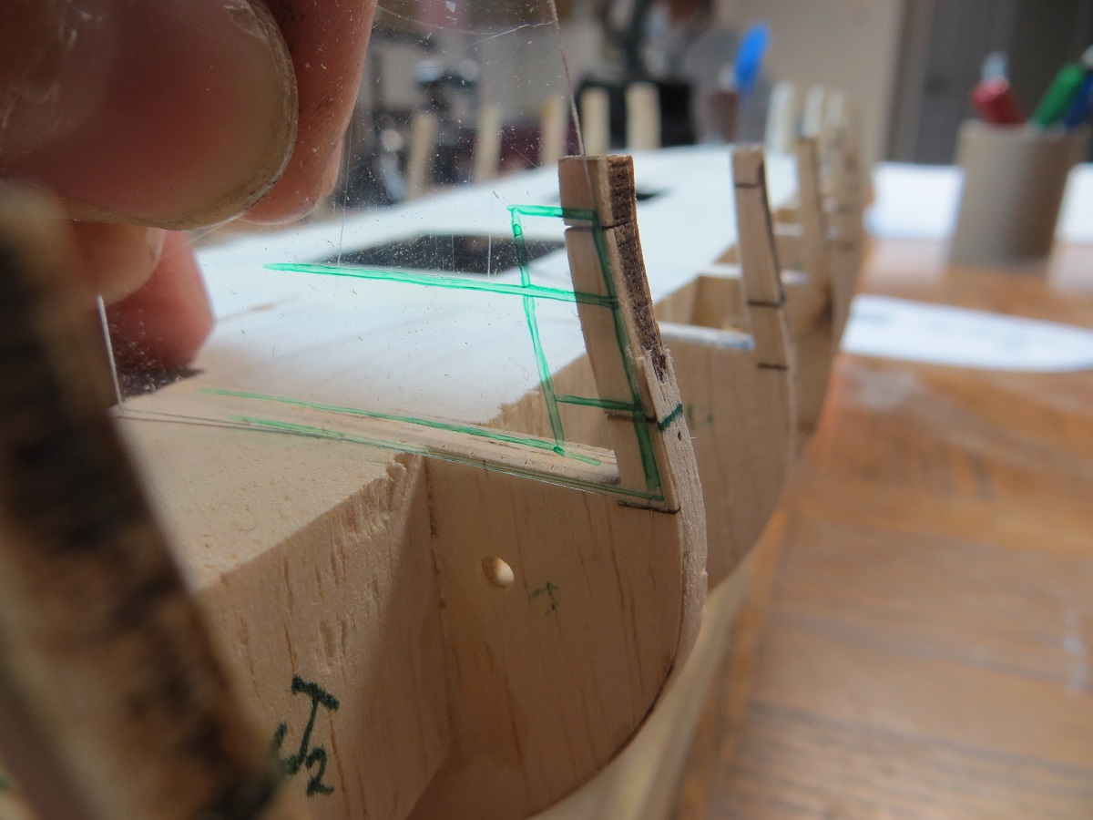
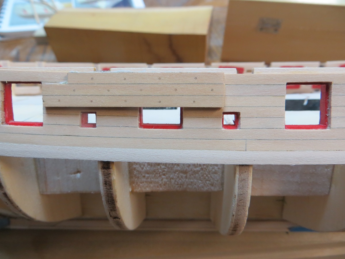
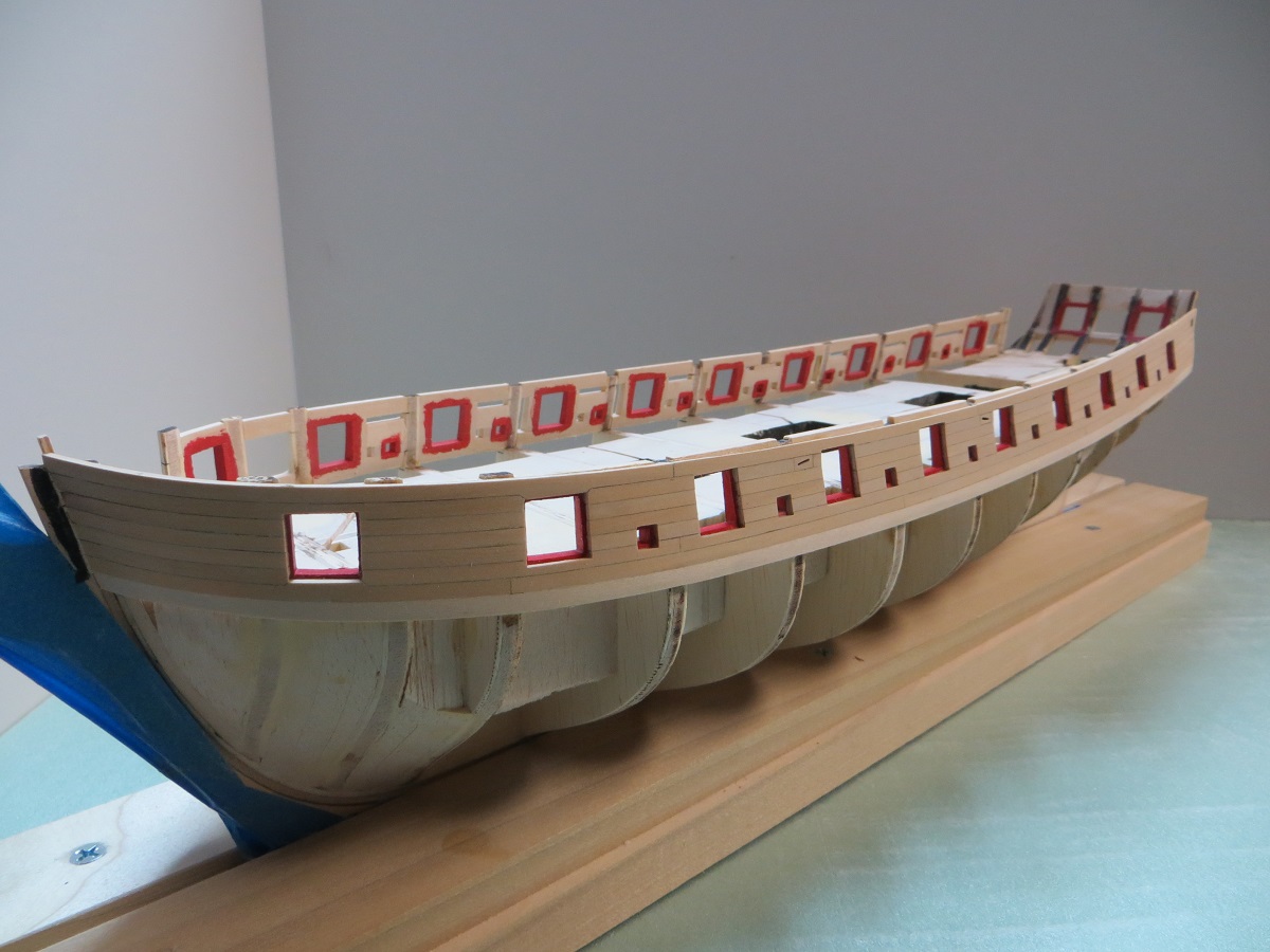
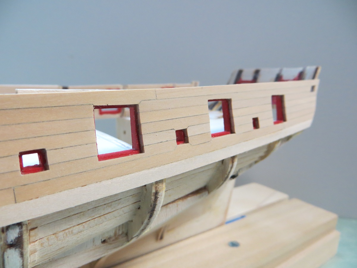
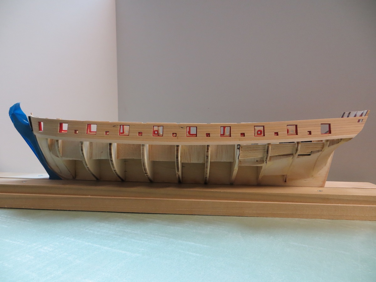
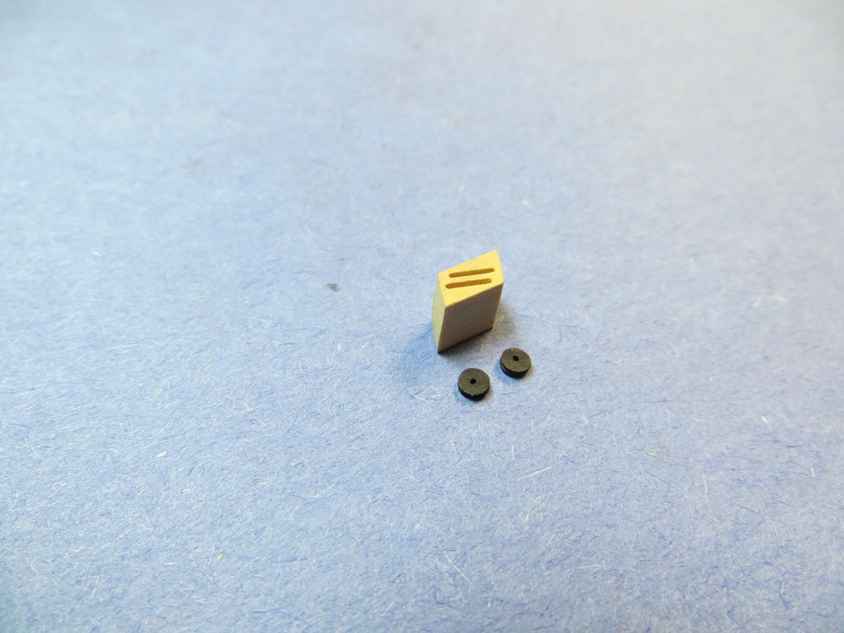
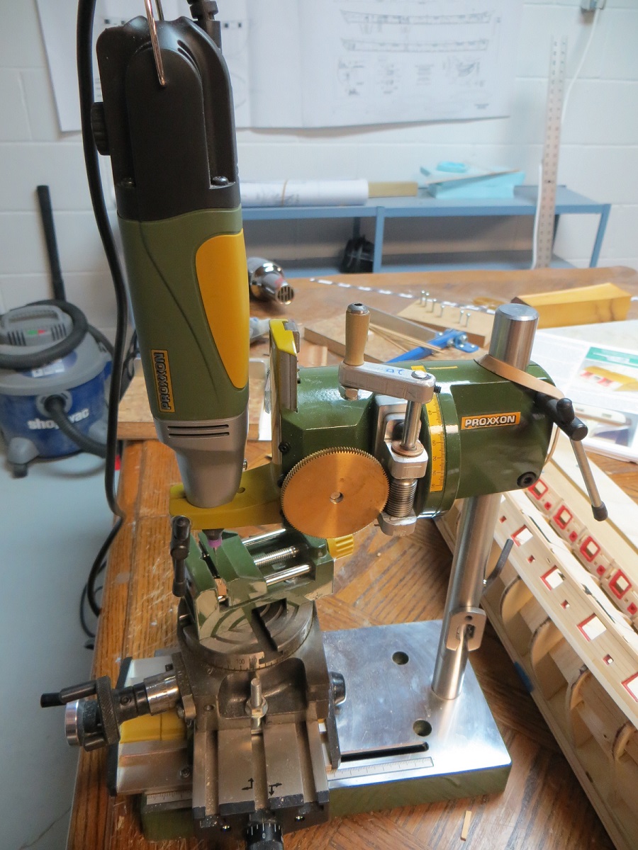
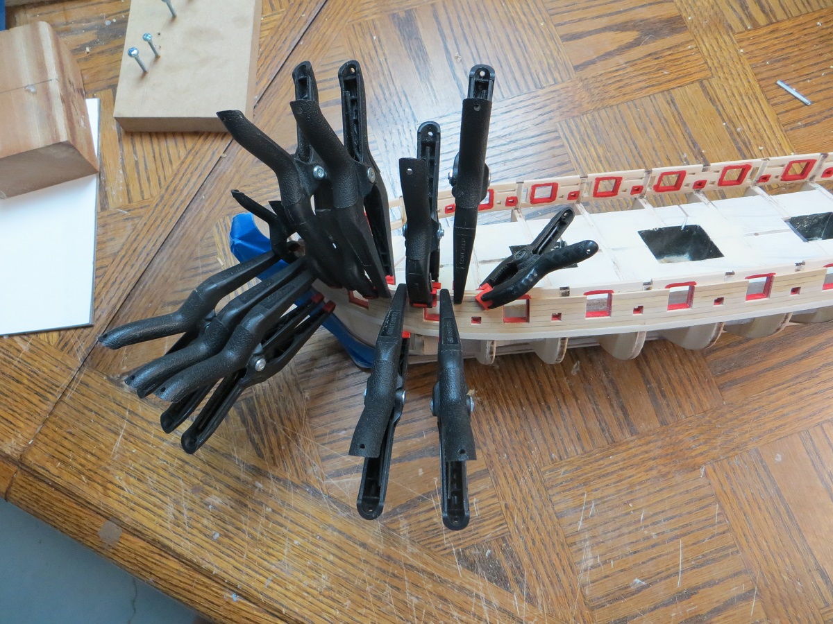
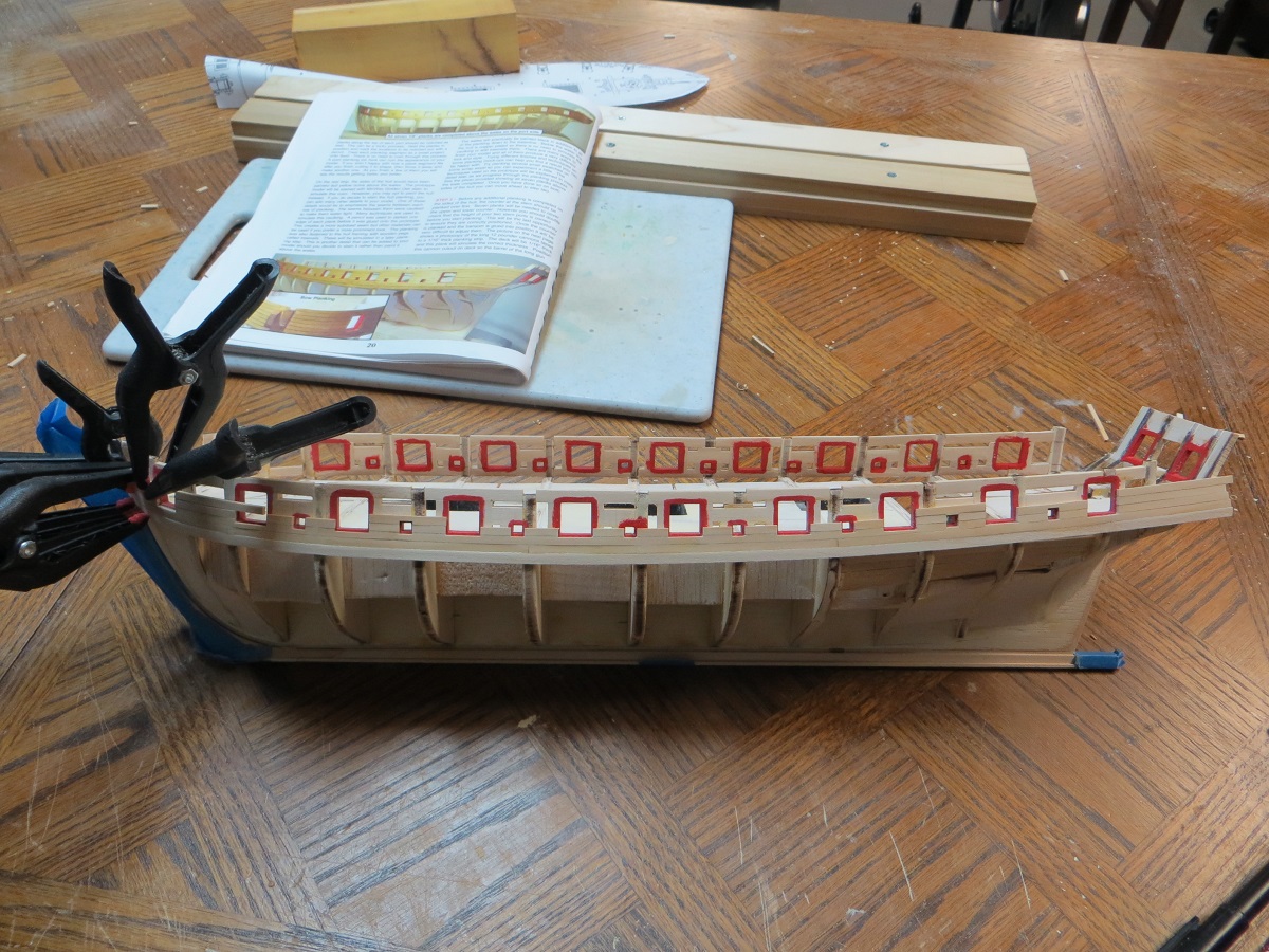
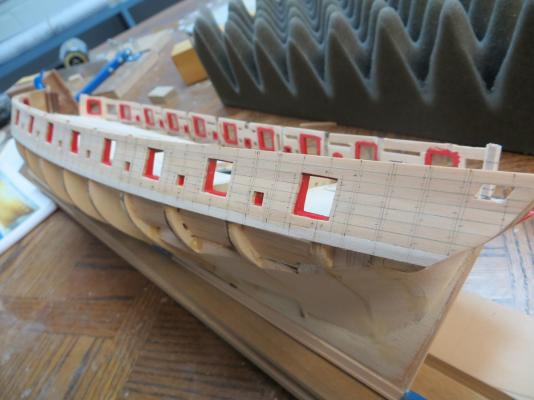
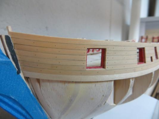
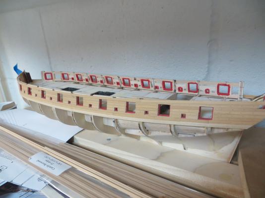
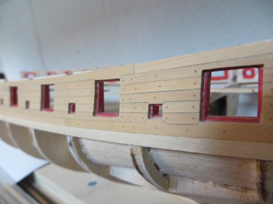
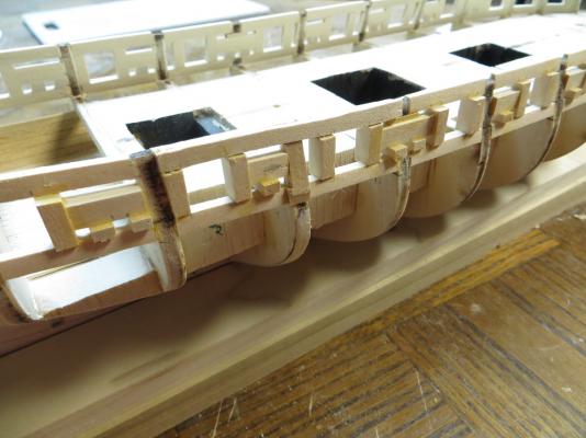
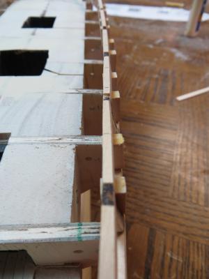
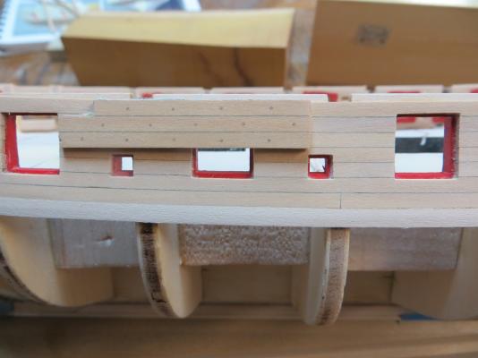
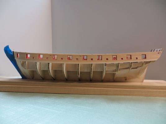
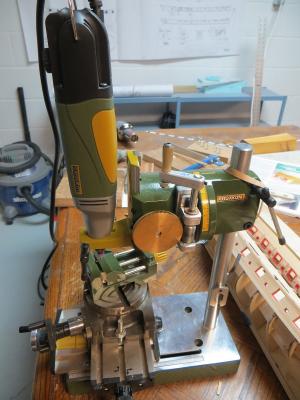
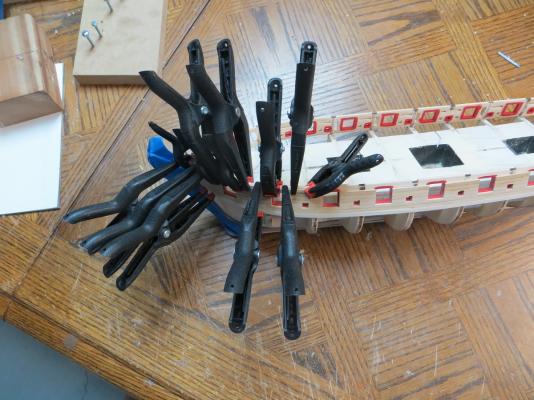
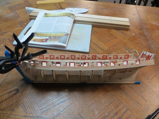
Another big update. Following the instructions, I worked on setting the sills, lintels, ports, etc... I made a template of the gunport on a clear piece of plastic sheet, so I could compare it to the model. Based on that, I know that the position of the guns in the ports may not all be at the same height. For example, in the picture below, the gun will sit slightly high compared to the port. I could have hacked away at the bulkhead to fix this but I think I would have ended up with a "lumpy" line of the gunports trying to make them line up. In the end, I decided a nice, clean line of the ports was more important, and I would worry about the detailed gun positions later. (maybe this will come back to haunt me...) Template: This gun will sit high: After all the sills, lintels and ports were in place, I noticed that some of the lines weren't flowing smoothly, so I had to add some filler materials in and sand them down to clean things up. I made this rotary sander thing for my Dremel out of a couple of milk jug lids (a few minutes of time well spent). It made quick work of sanding everything down. Slight dip in the line: Added some fillers (man- that picture looks rough): Sanding disc thingy out of a milk jug lid: Some pics of everything before planking: I decided to plank one side at a time, so I could make all my rookie mistakes on one side, and fix them for the other. I went ahead an upgraded to Castillo Boxwood for the planking above the wales. This is really nice wood to work with. My previous modeling experience with wood has been balsa and basswood, so I was completely blown away by this stuff. This boxwood is incredible for carving, shaping and holding an edge (no wonder it is popular for model ships). Partway through the planking process: It seems I cut almost every plank 2,3 or even 4 times before I got them right (-ish). Really frustrating (but fun) to re-cut a simple plank with 2 square butt several times just because that last stroke of the sandpaper took off just a bit too much. Even more frustrating to work on a really complicated piece only to mess it up on the sanding stroke. I now have a nice bin of small boxwood scrap pieces... Clamps, lots of clamps: For no good reason, I decided to machine the sheave blocks and add pulleys. Fired up my little Proxxon setup and turned the pulleys out of Hornbeam and the blocks from Castillo Boxwood. Again, I was really impressed with the boxwood for machining. Proxxon setup: Block and pulleys: There really is no need for this but it was fun anyway. Even the Admiral was impressed. Some pics of how she is now, before final sanding, treenailing and finishing: Still deciding on the treenailing method. Here is a sample using the method in the instructions, with a single coat of wipe-on poly: That's all for now.


- 17 replies
-
- 10
-
-
- syren
- model shipways
- (and 1 more)
-
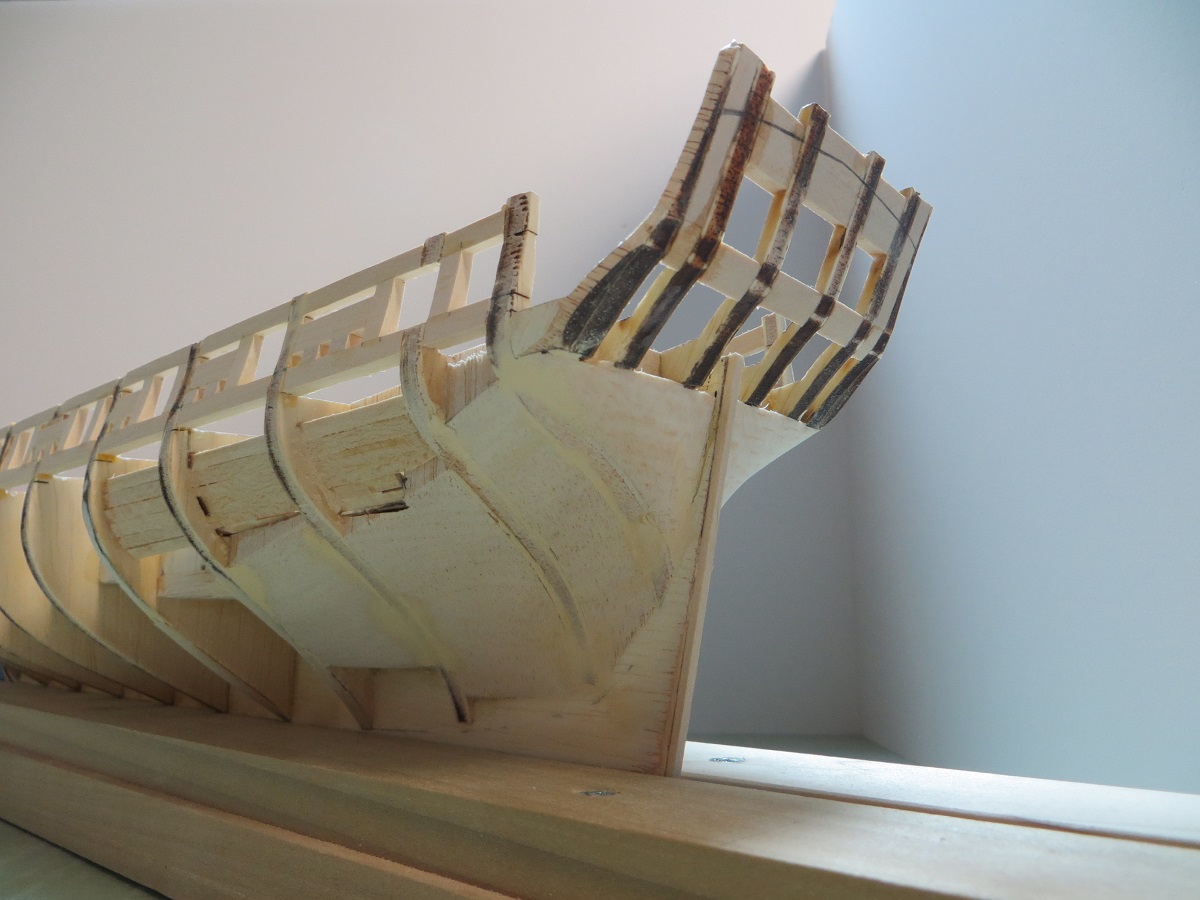
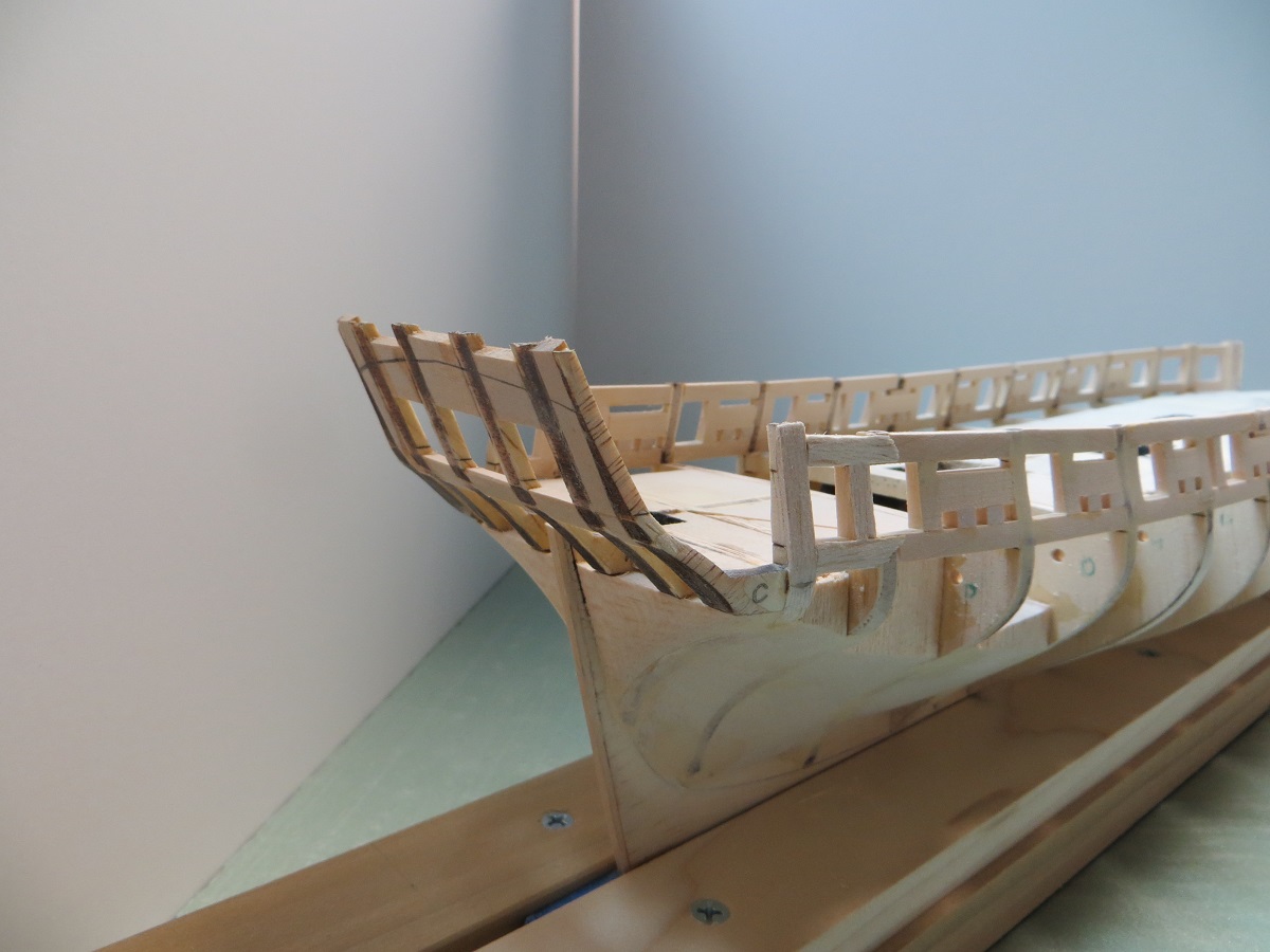
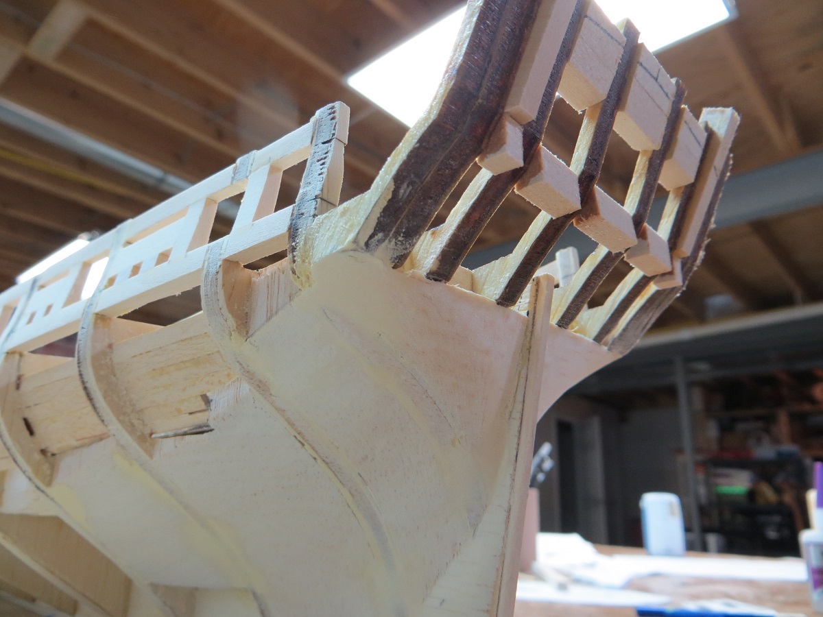
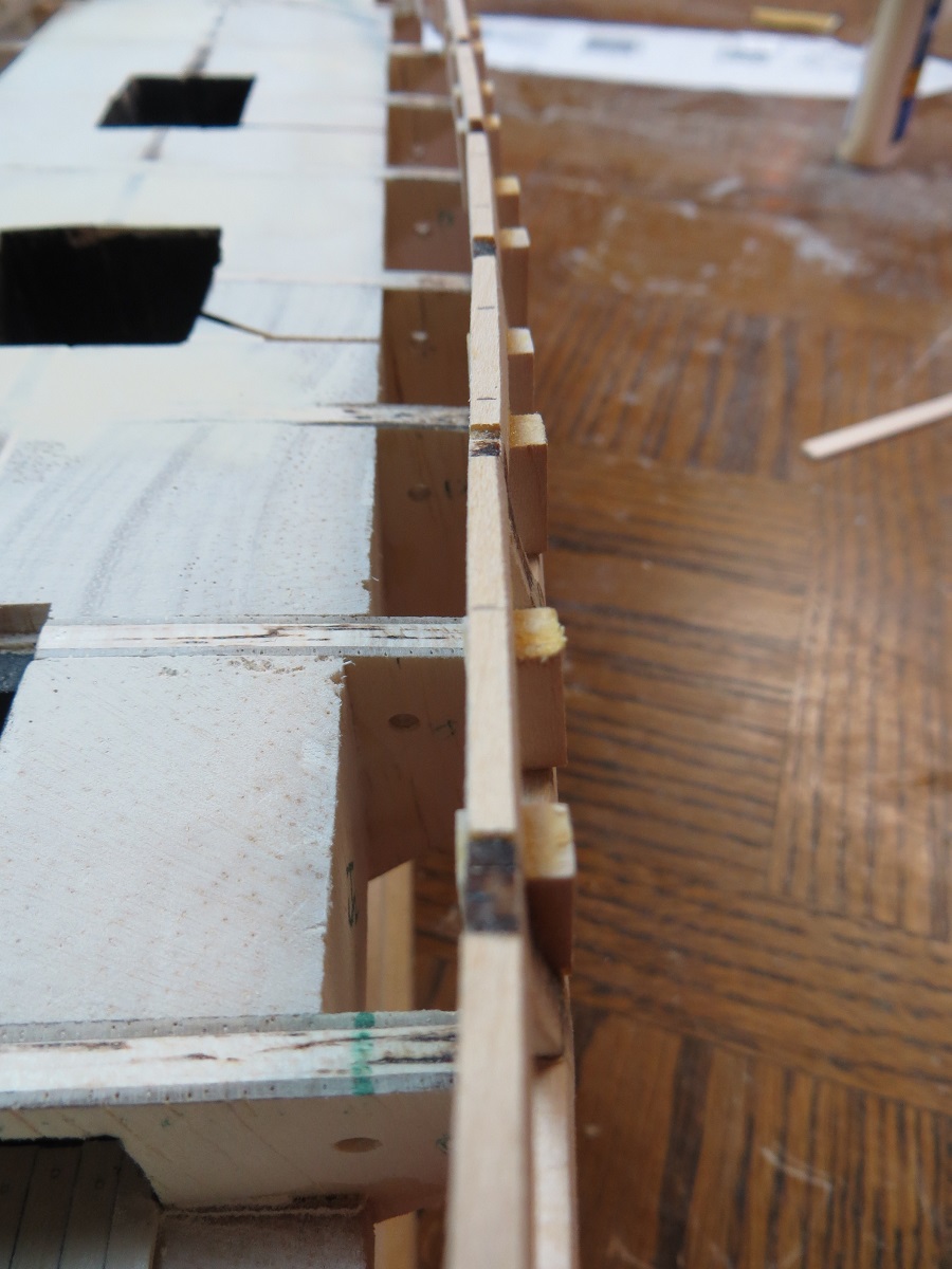
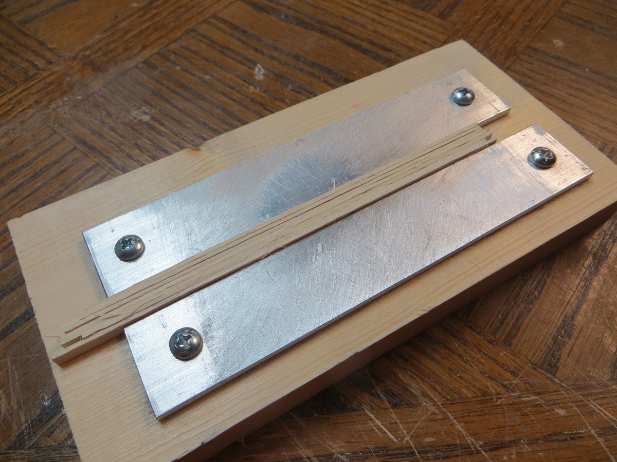
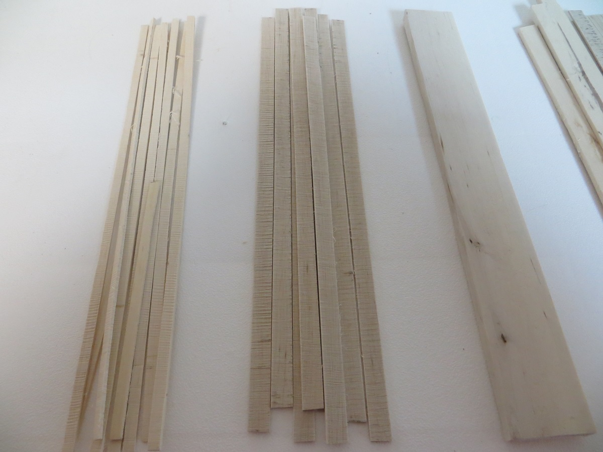
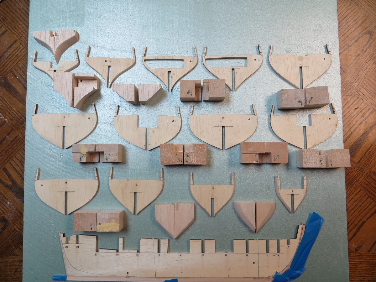
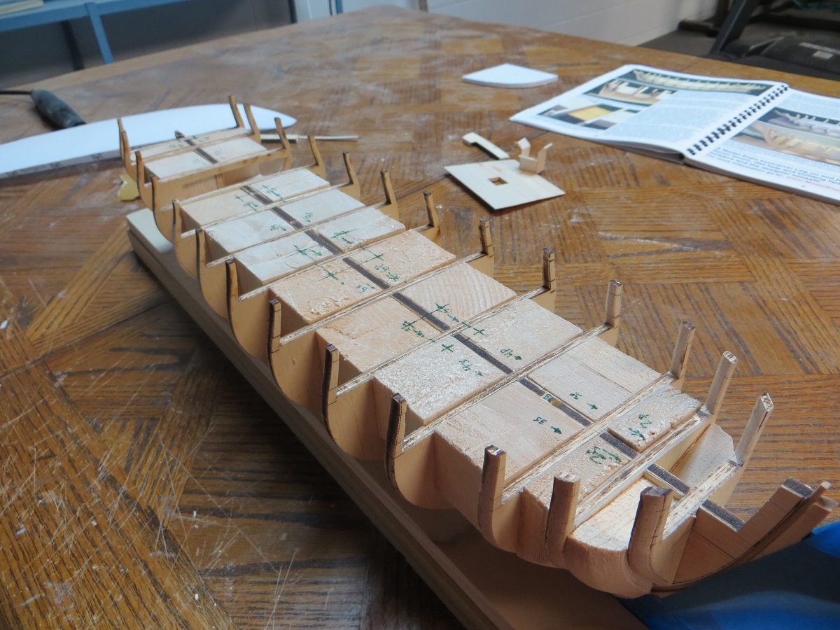
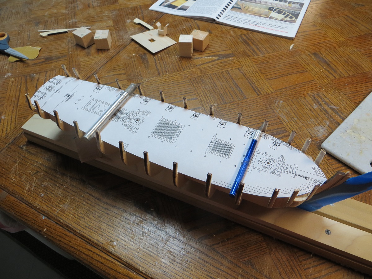
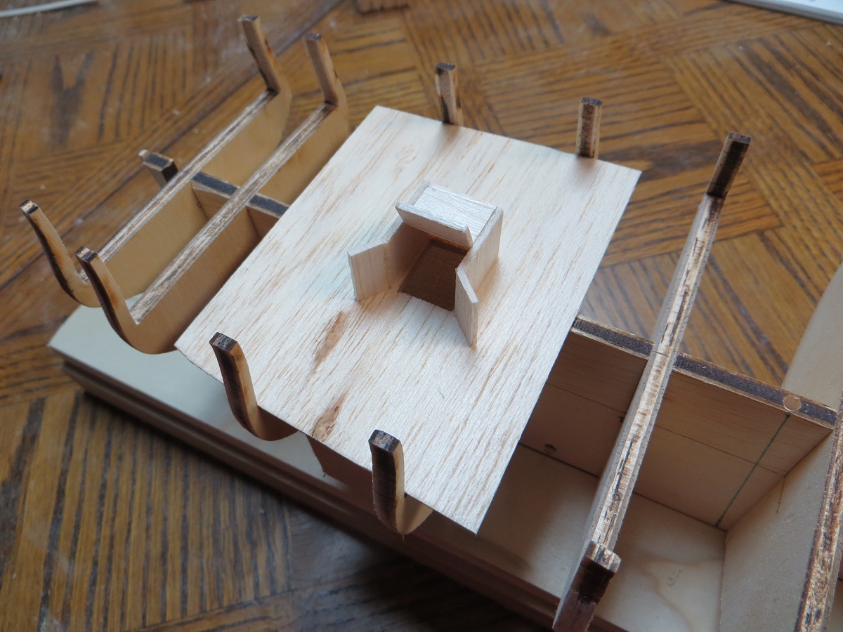
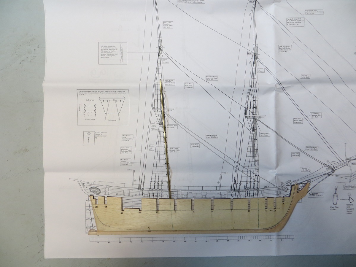
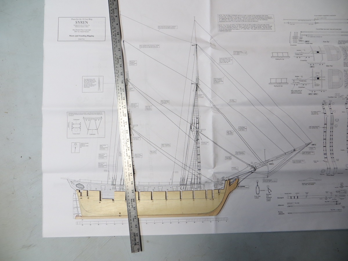
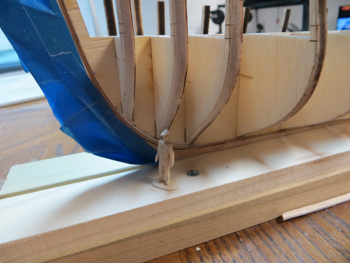
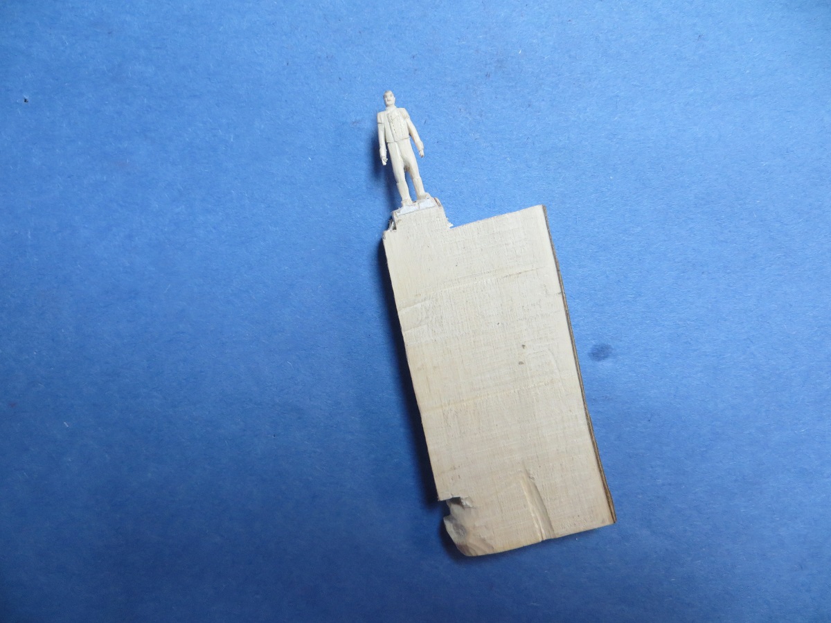
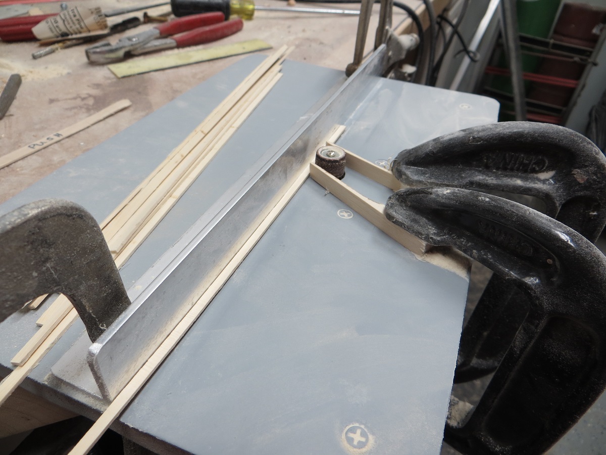
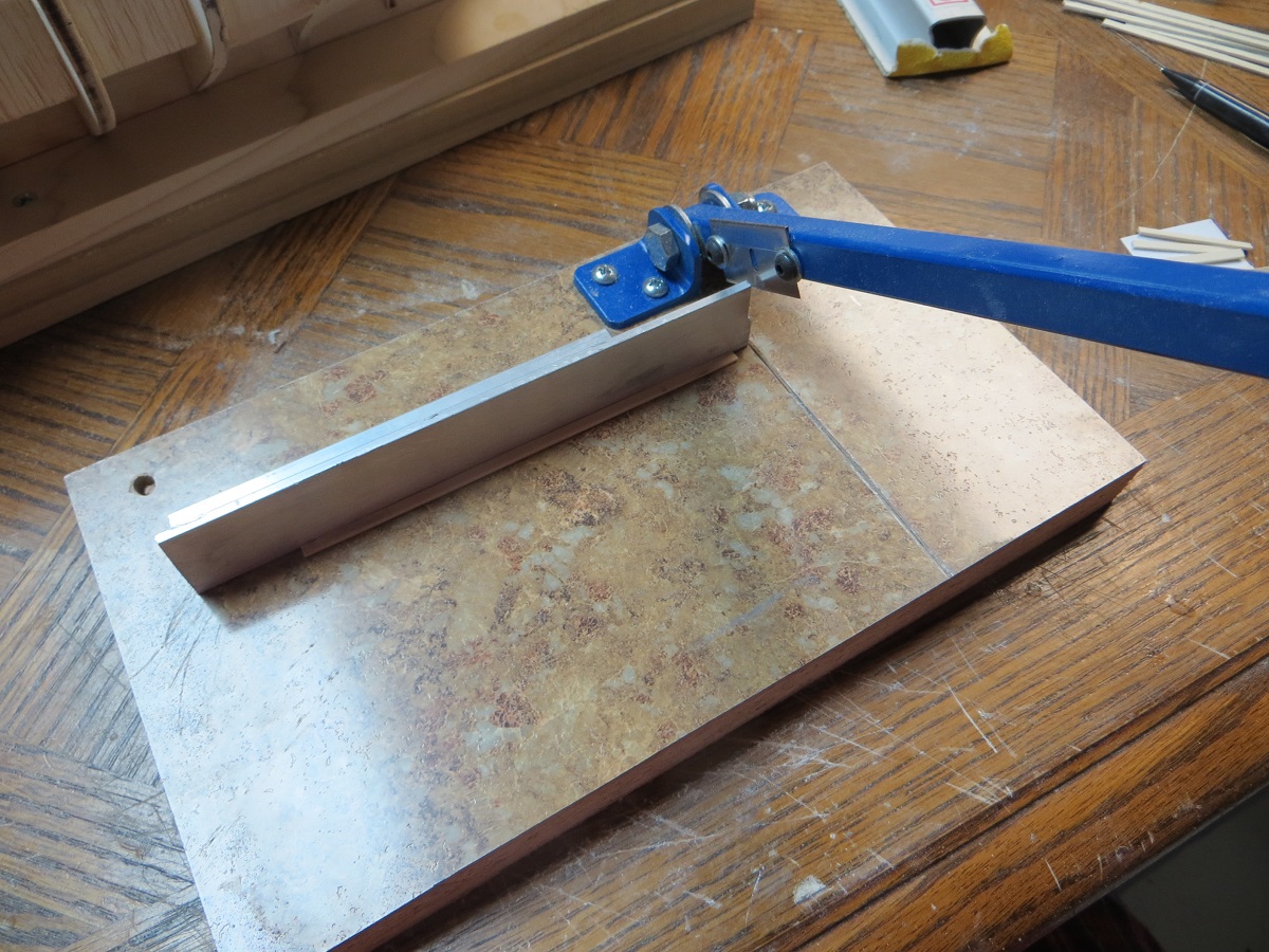
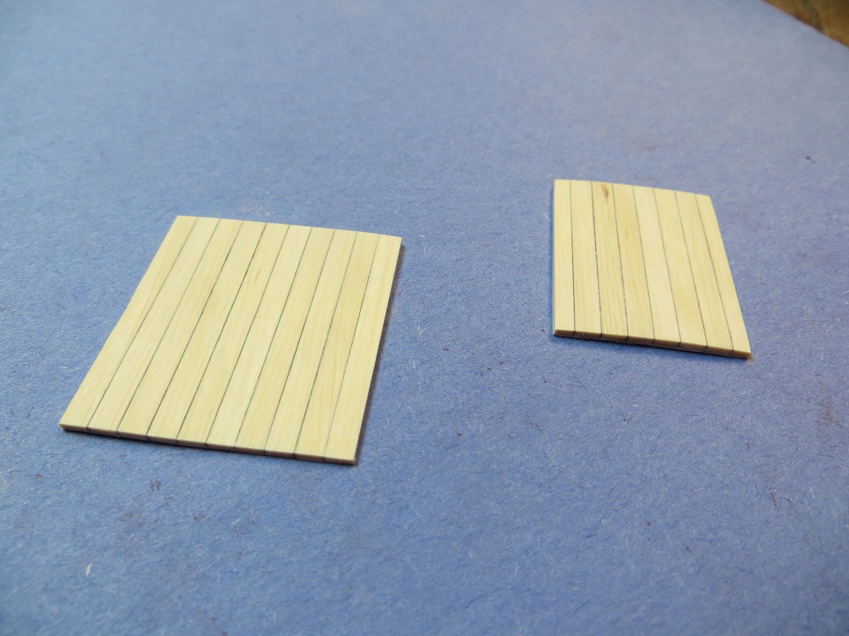
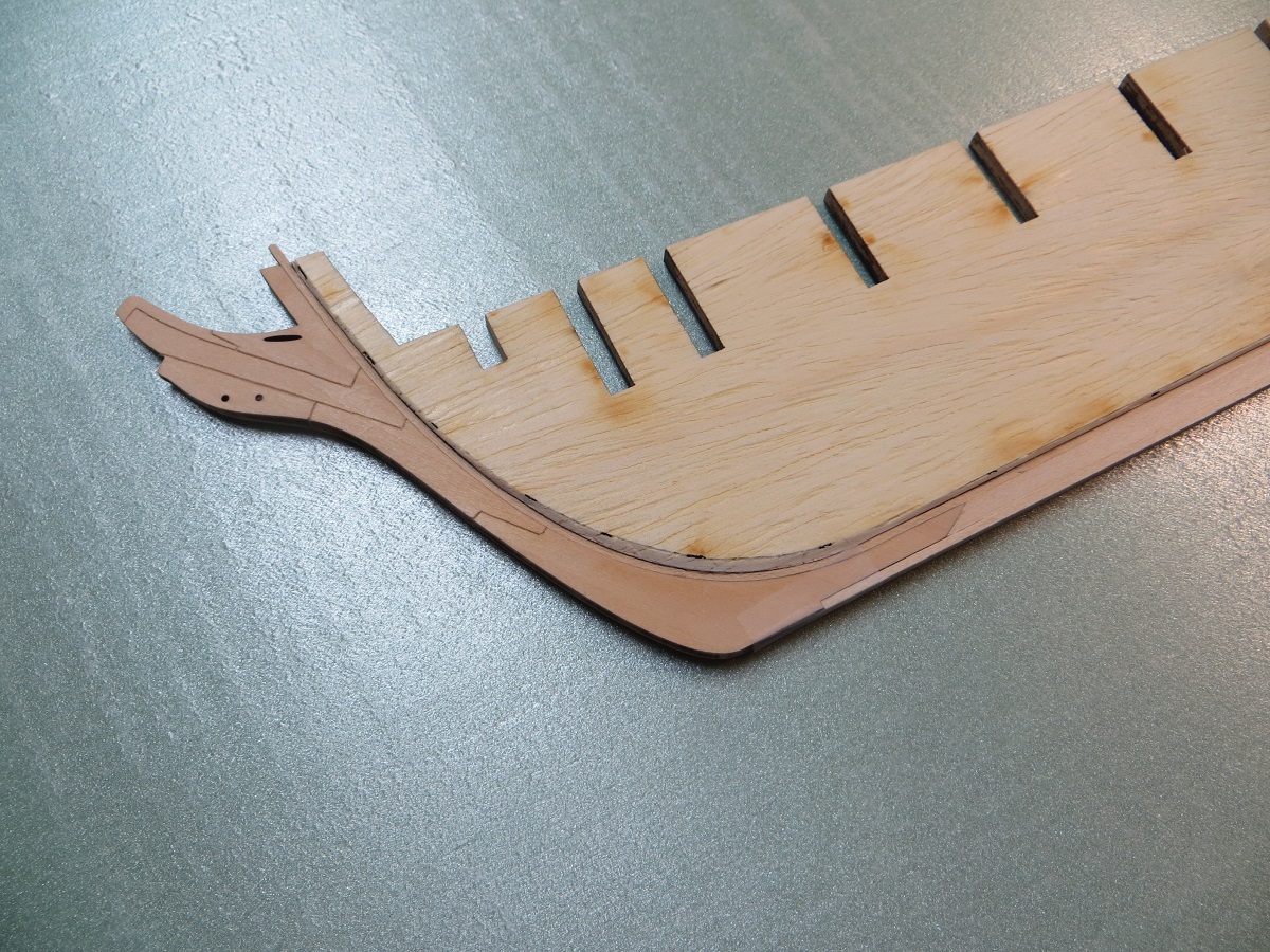
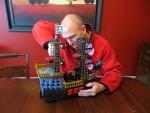
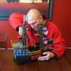
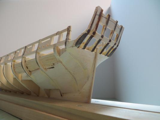
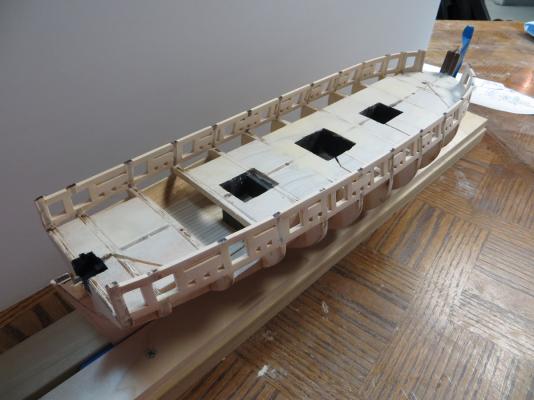
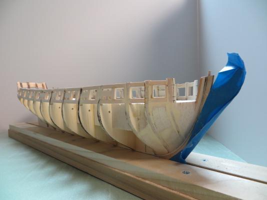
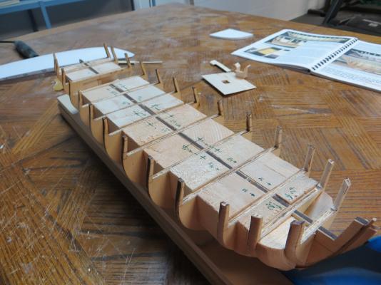
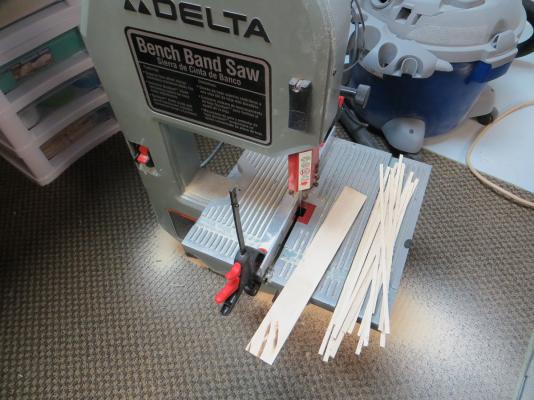
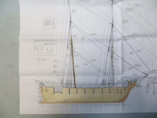
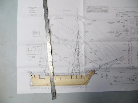
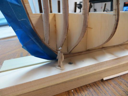
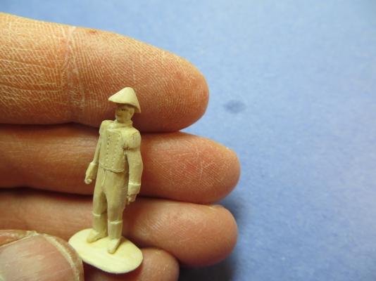
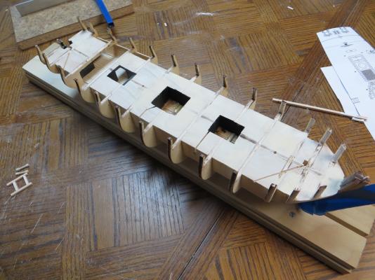
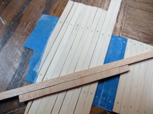
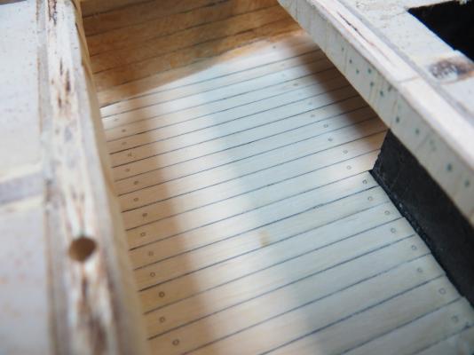
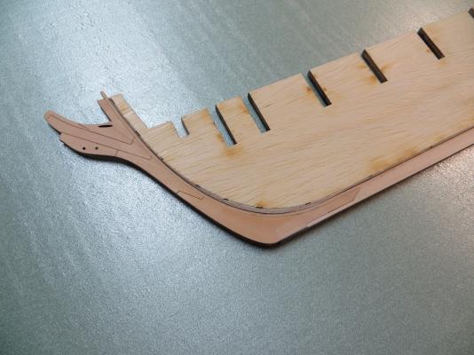
Still working on Chapter 2 of the Syren build, but I managed to collect a few pics along the way. Figure I ought to share before I get too far behind. Chapter 2 is about placing the bulkheads, filler blocks and fairing the hull. I had to complicate things a bit because I wanted to add some subtle lighting to the ship - not a disco, just some very gentle lighting. After going through it all, I don't know why I want to do this... Before I got too far on the bulkheads, I decided to drill some pilot holes for the masts into the bulkhead former. I guess it is easier and more accurate to do this now that latter on when the hull is built up. Looking forward in the instructions, I couldn't find any detail on how the masts get secured. Is it typical to just glue them to the top of the deck? Here's the former laid out on the plans to set the angle: Then the former was set up in the Proxxon drill press (the Timber's B Shiverin Shipyard finally made an investment in some tools...) and pilot holes drilled for the masts (1/8" holes I believe). A side benefit of drilling these holes is that it gave me a good reference to layout the deck plan upon. Pilot holes double-checked versus the plans with some brass rod: Because I plan to light the ship, I wanted to open up the space under the 2 main deck hatches and the small opening at the stern near the rudder. I hacked away at the formers and fillers, making a pocket that is roughly the same depth as the deck at the companionway. The pocket at the stern was not as deep, maybe only 1/2". I mocked up the hatches and lighting. The view through the hatches is very limited, only a mostly vertical view will reveal anything "below deck", so the walls are painted black. Laying out the deck plan, using the mast pilot holes for reference: Hatch locations marked: All the formers and fillers before assembly: Everything assembled, with the hatch walls painted black: I got pretty bored of making the filler blocks, and somewhere along the way got distracted by trying to practice my carving skills. I have no experience with this and I think I want to eventually try carving the figurehead and quarter badges, so I need to practice. I decided I needed someone to oversee this shipwreck, so this guy was whittled out of a piece of hornbeam (aka blue beech). He ended up pretty rough and I still need a lot more practice before I get to the figure head but you gotta start somewhere. It gives an interesting sense of scale. I think of the Syren as a fairly small ship but when you compare it to the height of an average man, you realize how big it actually was: Back on track... At the companionway, I knew that more of the below deck area would be visible with lighting, so I mocked-up the companionway with balsa, just to see how much would be visible. Based on that, I hacked away the formers and fillers in that area too. The result was that the port side needed to be planked one additional former forward, and one additional former aft of the kits basic shape. This also meant that the planking would extend into the main hatch area. Companionway mocked-up: I also decided to plank the bottom of the hatches because they are barely visible (and for some planking practice). With the basic shapes defined, I needed to work on planking. Again to complicate things, I decided I wanted to use Hornbeam for the decking. I have no experience with other woods besides the Basswood in the kit but the Hornbeam seems much better to work with. It is much harder, and cuts/sands/works well without leaving any fuzz or fibers. It is also a more white/grey-blue shade than the tan of the Basswood. Another reason to use Hornbeam is that I have a source for it - my family's woods, so that means the price is right too. My father had several pieces already cut and dried, so I proceeded to turn those into some planking. Once again, the Timber's B Shiverin Shipyard's limited budget prevents me from getting really nice stuff (I keep looking for someone to place a Byrens table saw on the curb for recycle day but it never seems to happen...) so I had to make due. Here's a picture of some Hornbeam. The right side is the rough board, the middle shows the more grey heart wood, and the left shows the lighter sap wood. I will be using the sap wood, however, the grey would make for a nice, weathered look. The plank making process goes like this: Rough board ripped on the band saw: I had to make a router table for my Dremel. It was pretty simple to make, and the accuracy is decent as long as I don't try an remove too much material in a single pass, and I replace the sanding drum regularly. I have some ideas for my belt sander but that will have to wait. Homemade Dremel router table: The planks are then chopped to a shorter length on my homemade chopper: Then sanded to final, uniform width (1/8") on this jig: The planks are then mocked into position, tape applied to the backside, and given another sanding for uniform thickness. Here are the planks for the companionway area, with a couple of sticks of Basswood on top for comparison: I also decided to treenail the companionway area, mostly for practice. I think the treenails are a little too pronounced, so I will try and tone them down in the future. I did the treenailing before final installation. The treenails and "chalking" used the method described in the instructions. Here are the plank sections for the hatch areas: Wow - that's quite a post. Maybe I should try and update more often?


- 17 replies
-
- 12
-
-
- syren
- model shipways
- (and 1 more)
-
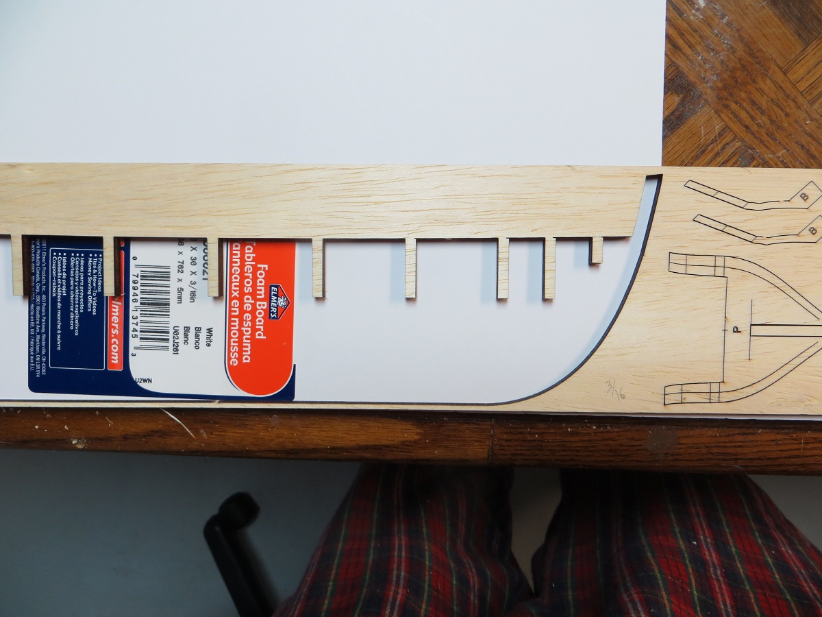
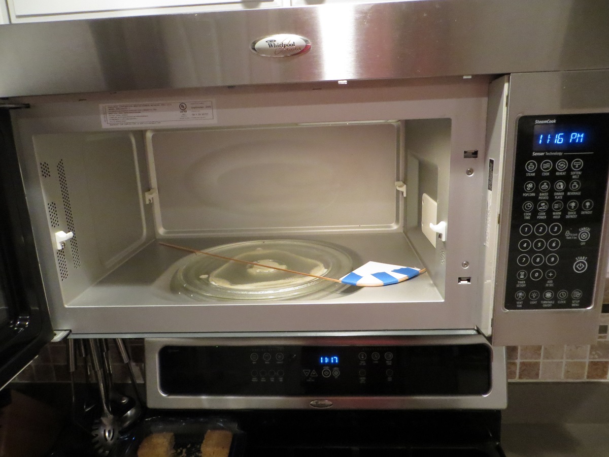
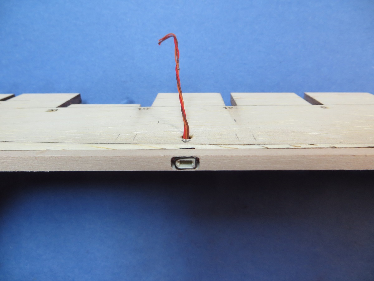
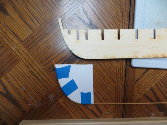
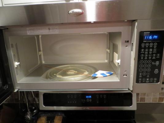
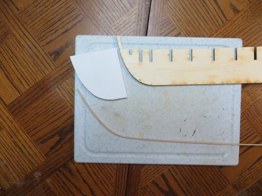
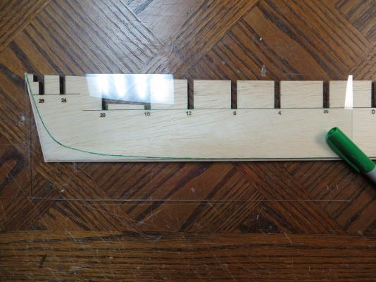
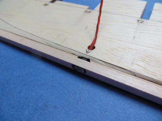
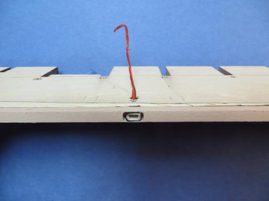
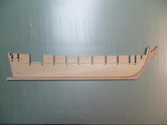
Hello everyone. Please allow me to introduce myself. My name is Brian, and this is my first model ship build. I have been playing with models (mostly RC cars and planes) for years. I have always wanted to get involved in model ships (I bought Wolfram Zu Monfelds book 20 years ago just because it was so neat) but I guess I have reached a certain maturity (?) and level of patience (I hope) to try and build one. I hope you enjoy watching a rookie hack his way through his first build via this log. Onto the build… I decided the MS Syren would be a good start point. As much as I would love the look of a muti-deck 74-gun, I think I should get my feet wet with a single deck, 2 masts and 16 guns. Also, this model has been built by quite a few people who have been generous enough to post their experiences here. Those logs have been incredibly valuable so thanks to all you folks building Syrens. After some “re-tooling” of the work area to change from planes to ships, the build began. Chapter 1: Nothing too special here – just following the instructions. I did a few things differently though: 1. I built the keel holder first. I used it right from the beginning of the build. It was nice to have when placing the rabbet strip. 2. When it was time to bend the rabbet strip up the bow, I used a tip from my airplane days. Perhaps this method has already been shown here? I soaked the strip in water for 10 or 15 minutes. While it was soaking, I used the bulkhead former to trace the bow shape onto some foam board. I cut out the foam board, and then taped the soaked strip to it. I then popped it into the “admirals” weapon of choice (microwave – don’t tell her I said that) for about 30-45 seconds. That took a lot of the fight out of the strip, and it allowed me to easily hold it in place and glue it with medium CA. 3. When it was time to carve the bearding line onto the port side, I traced the laser-marked starboard side onto a clear piece of plastic from some clear packaging I found. I then cut that out and traced it onto the port side. Looking back, there were probably enough laser-marks through the bulkhead former that I didn’t need to do this . 4. I want to add some lighting to the ship. I have already been goofing around with some LED lanterns (http://modelshipworld.com/index.php/topic/9526-164-deck-lantern-lighted/). I would like to light the holds, companionway, binnacal and maybe some random lanterns on the deck. My plan is to run the wiring through the display stand, and up to a connector at the keel. Placing it at the keel allows me to cover the connector with the false keel, should I decide not to do the lighting. I used the thinnest connector I had but it still pokes just slightly through the rabbet. I don’t think this will be a problem for the planking later on. 5. Like some others have done, I added some detail to the stem knee. Not historically accurate, just a mash-up of something from Zu Monfeld's book. Here's the progress so far (I guess I took this pic before the electrical install): On to Chapter 2...

- 17 replies
-
- 6
-
-
- syren
- model shipways
- (and 1 more)
-
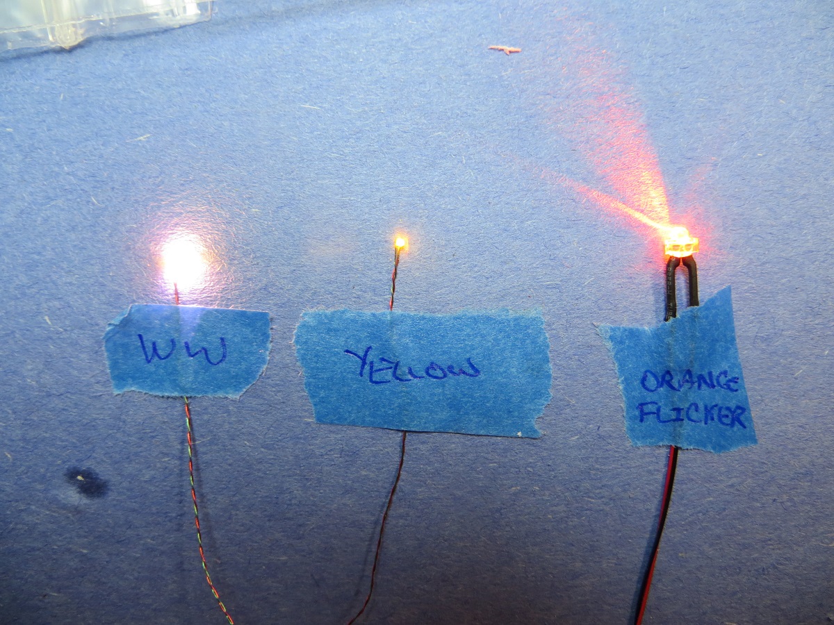
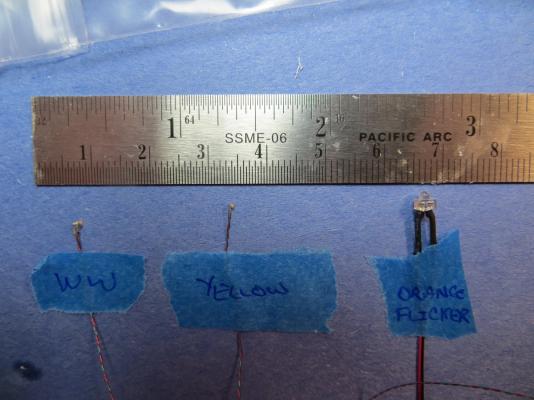
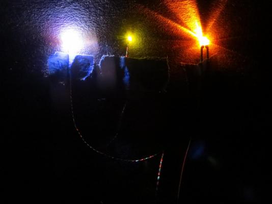
Thanks for the replies everyone. It's a fun little project. @mtaylor: Thanks for the link to the database - I hadn't found that yet. This site is a wealth of knowledge. Still so much to learn... @CaptainSteve and gjdale: The Timbers_B_Shiverin' shipyard is located at the corner of "Cheap" and "Dirtry" streets, across from the junkyard and downstairs from the worst bar in town. That explains the level of equipment and the disposition of the lead shipwright. Feel free to stop by anytime, and I can personally add one of these lanterns (and a lousy beer if you like) to your cart. Regarding the lighting, the vendor that I bought the lights from has quite a variety, so I went on a bit of an LED spending spree and bought a little of everything. The "pico" LED I used is "yellow". I also bought a "warm white" version for comparison. They also offer flickering LEDs, but not in the pico size (they offer it in a larger 1.8mm size, so it wouldn't fit inside this size lantern). I bought some of those in orange, thinking I can hide them in the hull. They offer a yellow, which I think would work better to simulate a lantern (orange looks more like fire). No resistors or other circuitry are required, just plug-and-play with a 3V source. Here are the "Pico" warm-white, yellow and 1.8mm orange flicker side-by-side (unlit, lit, and no ambient light). I have noticed that the intensity of light from the pico LEDs varies from part-to-part, so I will have to sample a few pieces to match the level I am looking for.

-
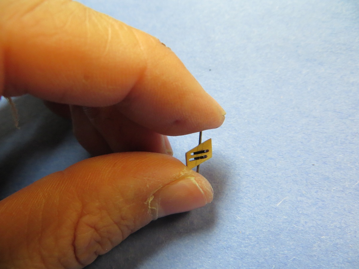
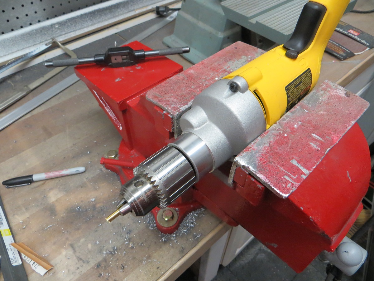
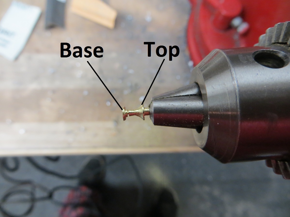
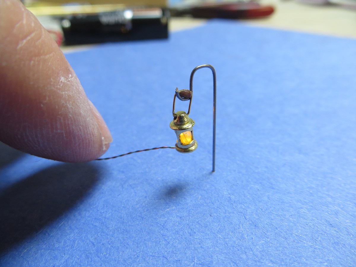
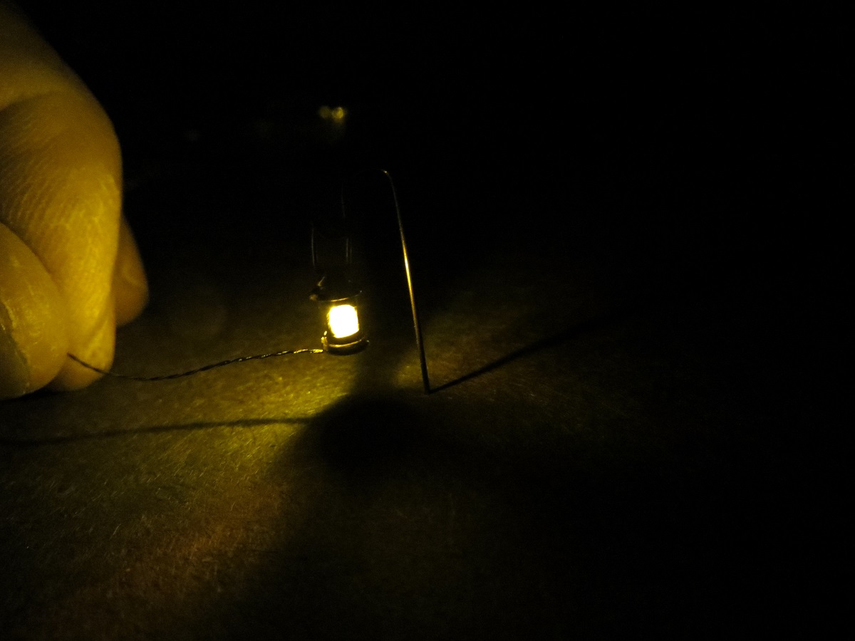
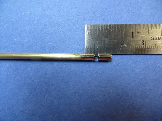
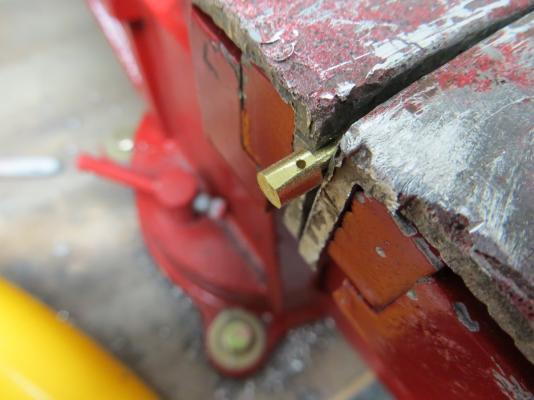
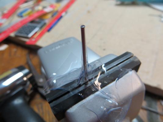
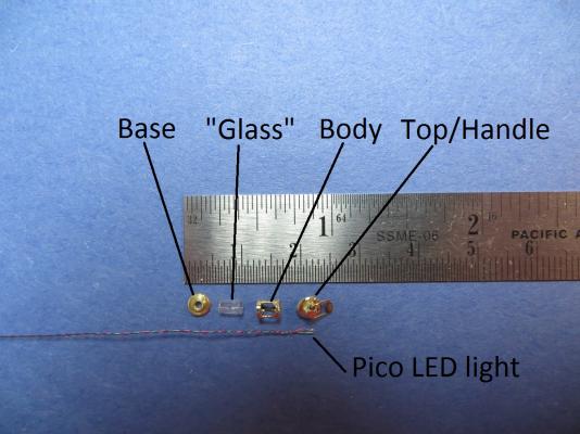
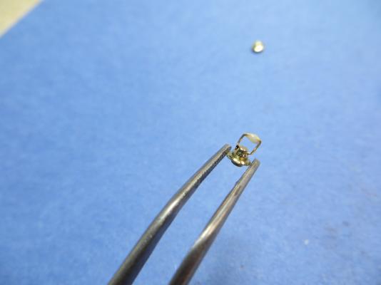
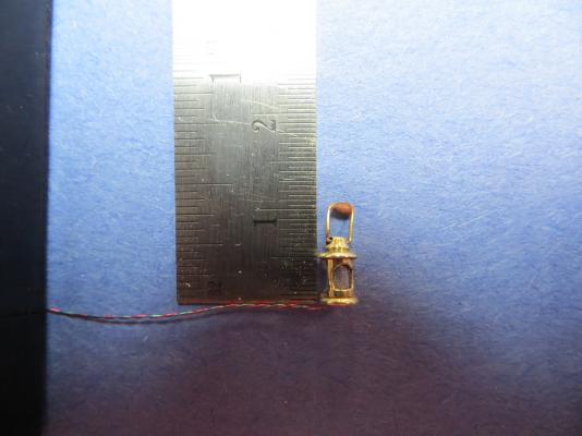
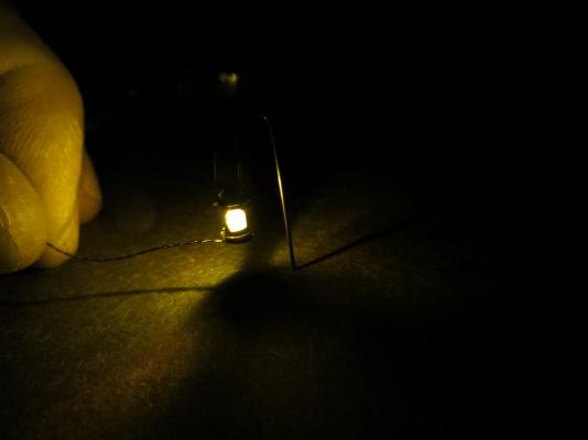
Hello everyone. This is my first post here and new to model ship building. This is supposed to be the start of a build log for a Brig Syren by Model Shipways (yes - another one for the armada) but seems like myself and everyone else in the model ship building community decided to order kits at the end of last year, which means mine is currently back-ordered. So in the meantime, I thought I would hack away at a detail - a few deck lanterns. The idea was to make a lantern that would be carried by hand or hung on a fixture on the deck. I have seen pictures of historical ships that have lanterns hanging from the ceilings but I assume they must have had other portable lanterns for working on-deck during the night. Any of you naval experts know of if/how this was done? If it wasn't done this way, then this was just a fun exercise in making really tiny brass stuff, which should be helpful when my ship actually arrives... Here is how I made a prototype. Hope it isn't too much for a post. I assumed that a lantern was roughly about 14" tall, which in 1:64 works out to about 5.5mm tall. I needed to make a body, top, base, glass, handle and lighting. I suppose most of this could have been made out a single piece of brass and turned on a lathe, but that would have taken away the fun of trying to hold a fiddly little piece of brass in your fingers. Here are the final pieces before assembly: For the body, I started with 1/8" brass tube, and filed 3 slots for the "windows" of the lantern. I left it attached to the base tube for as long as possible to make it easier to work on. This took files, Dremel tools, and carving with a knife. it was then lightly polished. The top and base were turned from a single solid rod of brass using my highly accurate Dewalt vise lathe: I needed to drill a hole in the top to allow for the handle later on, which is much easier to at this stage instead of waiting until it was nearly finish turned. Fortunately, my Dewalt vise lathe also has a milling and pin-drill bit attachment, so I proceeded to slowly consume most of my pin drill bits making a tiny hole: More by luck than skill, I was able to turn both the top and the base at the same time: All the brass parts where then polished. I then needed to make the "glass", which I decided to make using a heat-and-stretch method with plastic. I found some thin, clear packaging plastic (I think it was from a package of 5-minute epoxy). Then I used a drill bit slightly smaller than the ID of the brass lantern body. Using my heat gun, I heated the plastic and then quickly stretched it over the top of the drill bit to form a cylinder. This took some trial and error but I finally ended up with something close. (Later on, I remembered that a lot of paint brushes at the art store come with little protective sleeves for the bristles, which might work just as well.) Brass wire was bent into a handle shape, and a small blob of epoxy was added and painted to simulate a grip. After looking at the macro pictures, it seems like this grip is too large, so I will probably file it down and repaint again later. Lighting was done with "Pico" sized LED, which is really, amazingly tiny. I found mine here: www.modeltrainsoftware.com For this lantern, I have the wires coming out of the bottom, assuming it would be set on top of some surface that would hide the wires. I also think I could route the wires out of the top and hide them in the handle so that the lantern could also be hanging. I assembled the pieces using clear glue. The final piece is about 7mm long, which is 1.5mm longer than I hoped (scales to ~17"), so future try 2 or 3 or 4 may get it right. Here it is with the LED on with the ambient lights on/off. Power comes from 2 "AA" batterys. I think in future iterations I might try to dim the light a little. (The LED instructions recommend a small coat of paint on the LED to reduce the intensity). That's all. Happy building! -Brian


- 11 replies
-
- 15
-