tartane
-
Posts
60 -
Joined
-
Last visited
Recent Profile Visitors
934 profile views


-
 Glen McGuire reacted to a post in a topic:
The San Marco mosaic ship c. 1150 by Louie da fly - 1:75
Glen McGuire reacted to a post in a topic:
The San Marco mosaic ship c. 1150 by Louie da fly - 1:75
-
Glen McGuire reacted to a post in a topic:
The San Marco mosaic ship c. 1150 by Louie da fly - 1:75
-
I'm going to stop this discussion because I'm not going to talk to anyone who says I'm dead wrong. Now there is no room left to talk about it. The message I sent was for Steven and I would like to hear his opinion. I wish Steven the best of luck with the model. He is building a nice model and I'm looking forward to him managing to make a working latin rig out of it. Constant
-
mtaylor reacted to a post in a topic:
The San Marco mosaic ship c. 1150 by Louie da fly - 1:75
-
mtaylor reacted to a post in a topic:
The San Marco mosaic ship c. 1150 by Louie da fly - 1:75
-
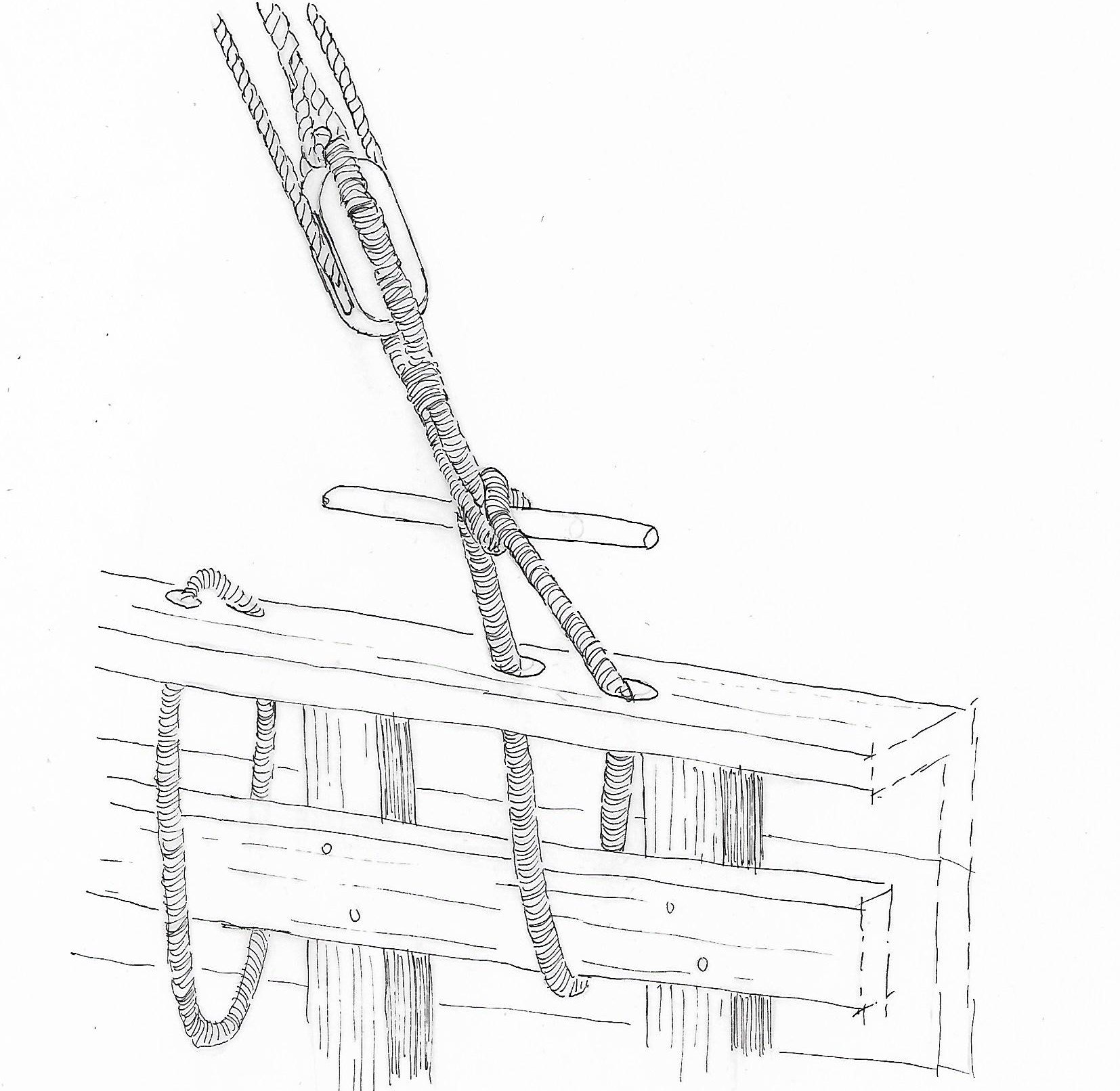
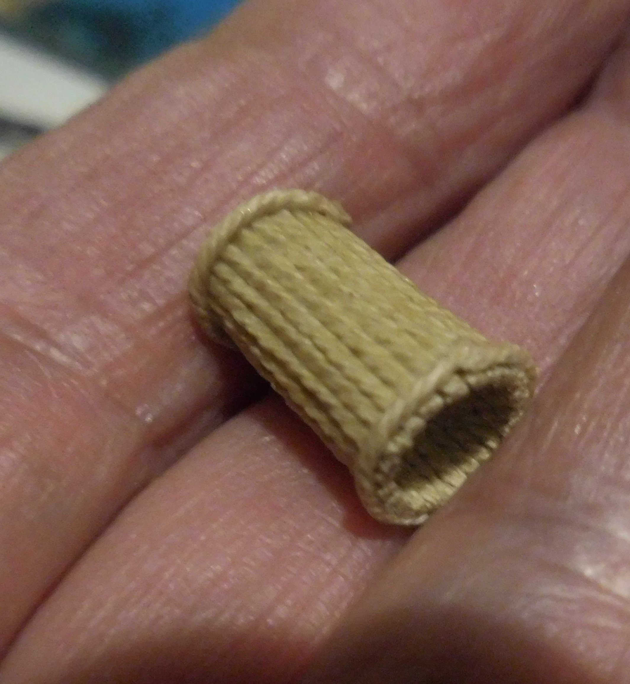
Something went wrong and I had not the opportunity to place a second picture, but here it is. This is a knevel. Constant

-
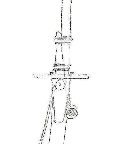
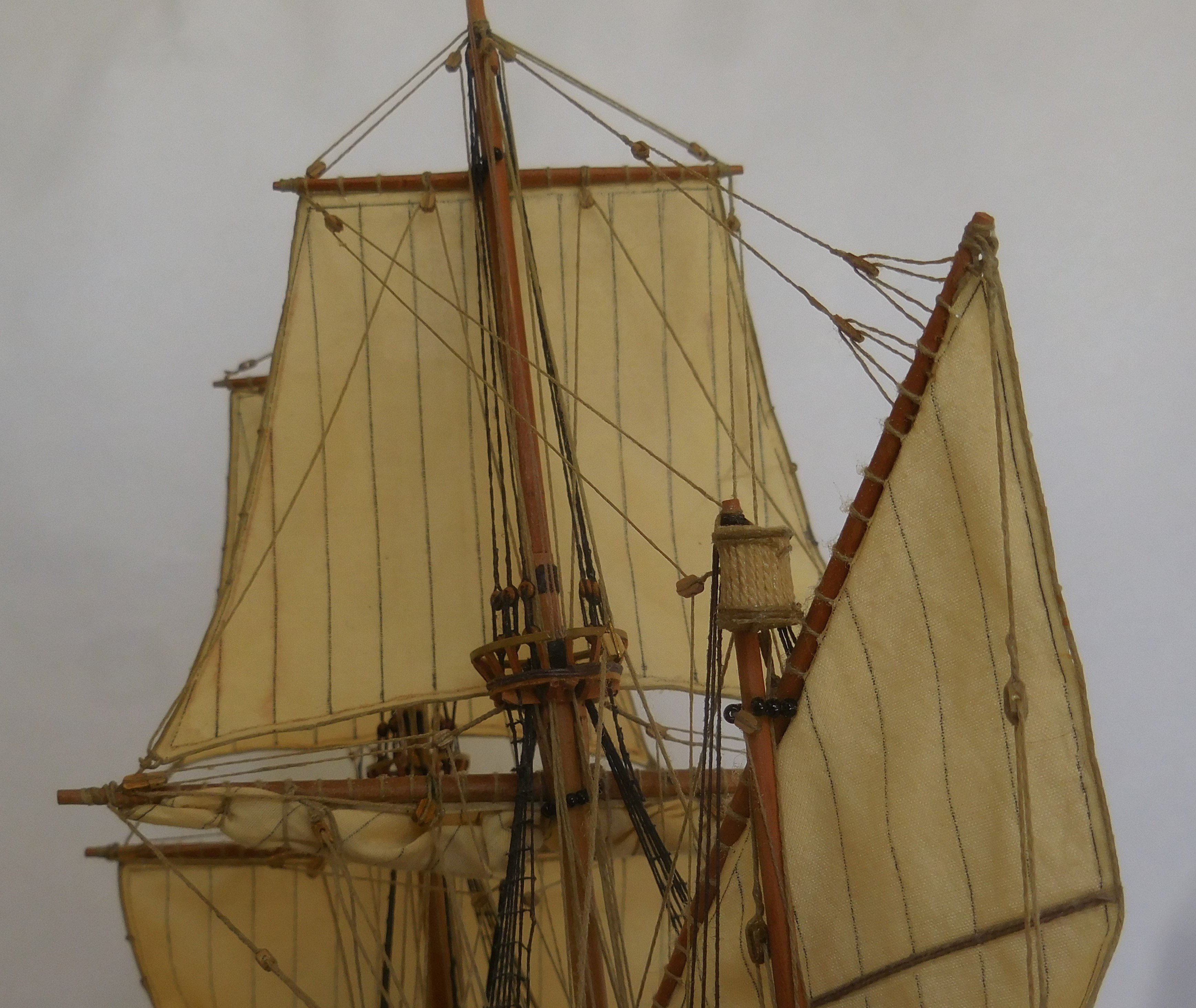
Steven Why do you make latin sails on your model? In all the images you show from antiquity, I only see square-rigged ships. To make these drawings more vivid, the draughtsmen used sails that were not quite quadrangular, and therefore they look like Latin sails. But they were quadrangular. Ships with latin sails never have crow's nests, which would make it almost impossible to convert the sails to port or starboard. If a latin rigged ship tacks, the rod and sail had to be turned around the front of the mast. That was a major operation in which all the shrouds were removed and all the ropes that were attached to the rod and sails. I have made several Latin-rigged ship models and did a lot of research on them beforehand. Also, latin-rigged ships did not have rope ladders and stays, which also had to do with the conversion of the sails and rods. The rigging of your ship most closely resembles the rigging of a cog. There I would also make so-called Knevels, I don't know the English word. They ensured that the shrouds could be removed quickly. By brassing the sails, cogs could sail quite sharply to the wind, and that is also the case with your model, for that you needed those knevels. I'll show you a picture of a cog I built from 1240, there you can see the knevels and also that the shrouds on the leeward side (here starboard) have been loosened for half, they hang along the mast. On the windward side you needed all the shrouds. This allowed the sail to rotate sharply without touching the shrouds. So far we know cogs had no rope ladders. See also https://modelshipworld.com/topic/36314-kogge-van-tartane-schaal-by-tartane-finished-187-reconstruction/ I'll also show you a drawing of a knevel, as they are still used on Latin-rigged ships in the Gulf of Oman to this day. I have made that construction on all my Latin rigged ships and also on the cog I don't want to interfere with your ideas about the construction of the model, but I'm a bit afraid that you will get stuck when you start making latin sails. You make a very nice detailed model! Constant
-
Old Collingwood reacted to a post in a topic:
Mary Rose by Baker - scale 1/50 - "Your Noblest Shippe"
-
Old Collingwood reacted to a post in a topic:
Mary Rose by Baker - scale 1/50 - "Your Noblest Shippe"
-
Old Collingwood reacted to a post in a topic:
Mary Rose by Baker - scale 1/50 - "Your Noblest Shippe"
-
Old Collingwood reacted to a post in a topic:
Mary Rose by Baker - scale 1/50 - "Your Noblest Shippe"
-
tartane reacted to a post in a topic:
Mary Rose by Baker - scale 1/50 - "Your Noblest Shippe"
-
mtaylor reacted to a post in a topic:
Mary Rose by Baker - scale 1/50 - "Your Noblest Shippe"
-
mtaylor reacted to a post in a topic:
Mary Rose by Baker - scale 1/50 - "Your Noblest Shippe"
-
 tartane reacted to a post in a topic:
Trireme Olympias by Richard Braithwaite
tartane reacted to a post in a topic:
Trireme Olympias by Richard Braithwaite
-
 tartane reacted to a post in a topic:
DUTCH PINAS 1590 by tartane - FINISHED - scale 1:87 - reconstruction
tartane reacted to a post in a topic:
DUTCH PINAS 1590 by tartane - FINISHED - scale 1:87 - reconstruction
-
tartane reacted to a post in a topic:
Mary Rose by Baker - scale 1/50 - "Your Noblest Shippe"
-
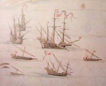
correction, Those images from the mid 16th century and earlier, Constant
-
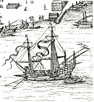
If you look for images from the 15th century, you will also come across this. There the bow is considerably lower and that seems logical to me in many respects. The captain and the helmsman now have a good view forward, which seems to me to be very useful in a naval battle. The bow now catches less wind. The excessively high bow of the MR seems to me very clumsy when boarding an enemy. The soldiers have to jump from very high to get on the deck of the other ship, I think I would break my legs. The highest guns have to shoot down, which seems to me to be rather impossible with the primitive cannons of the time. Constant
.jpg.a0c1c7a6d6a9502140c38ef2155a0958.jpg)
-
LˇAmarante by marsalv - 1:36 - POF
tartane replied to marsalv's topic in - Build logs for subjects built 1501 - 1750
Is it possible to post some photographs of the ship and his history? Constant -
tartane reacted to a post in a topic:
The Flying Dutchman by BLACK VIKING - first scratch build
-
tartane reacted to a post in a topic:
DUTCH PINAS 1590 by tartane - FINISHED - scale 1:87 - reconstruction
-
tartane reacted to a post in a topic:
DUTCH PINAS 1590 by tartane - FINISHED - scale 1:87 - reconstruction
-
tartane reacted to a post in a topic:
Cat Esther by GrandpaPhil - 1/64 - CARD
-
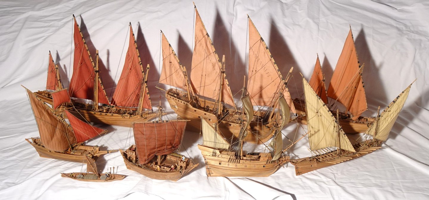
10, Pictures of the early Pinas. All ship models together so far. All on a scale of 1 : 87. Top from left to right; Chebec, Venetian Pinque, Ghanjah (Oman) Under; Tartane, Swelhals, Cog, Pinas, Galeotta. Not in the picture; Egyptian (Pharao time) merchant ship, English Canalboat, Stadsaeck (Zutphen 1684) See also; www.constantwillems.nl Constant


-
I am busy with the last episode. I show the photos in short time. Constant
-
Patric, To find out as much as possible, I think you have to divide the images that exist into two categories. The first is the collection of images depicting the ships actually sailing around, i.e. in the 16th century. The second is the collection of images that were made after the ships disappeared. So those drawings are based on the drawings that were already there and if they were not right, the imagination went further and further. So you shouldn't take that second category seriously I have experienced this clearly in my long-term research on the chebec, a Latin-rigged ship that sailed in the Mediterranean from about the year 1700 to about 1840. The drawings that were made at that time were very correct, and were made by a few draughtsmen who had also sailed on them. But after 1840 there are fanciful depictions of painters who were not familiar with these ships but who sketched a romantic and very exaggerated picture from the existing drawings. This was the reason why models of these ships were suddenly made long after 1840, which also ended up in the maritime museum in Paris. Those models were wrong and can still be seen there. There are curious flaws in it. Unfortunately, manufacturers of construction kits then started measuring those models, so that there are now construction kits on the market that give a completely wrong picture of those ships. There are a lot of things wrong and I never understand why the builders themselves don't see this. This also came up again and again in my research into the cog. If you wish, I would like to help you in this search. I admire your work in details. Constant
-
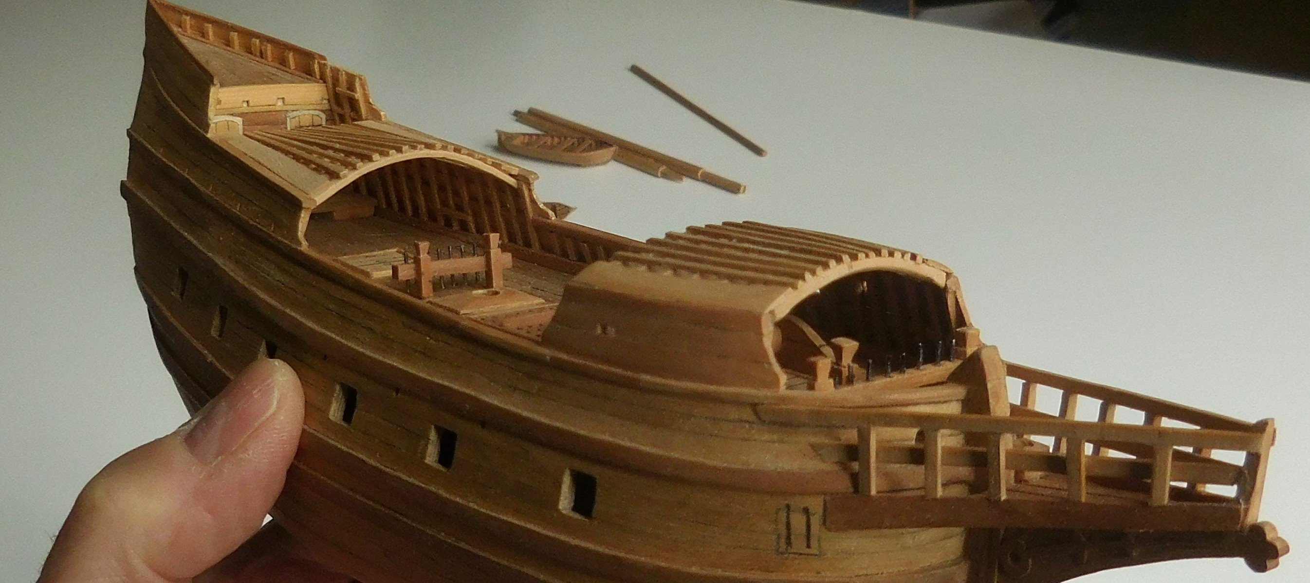
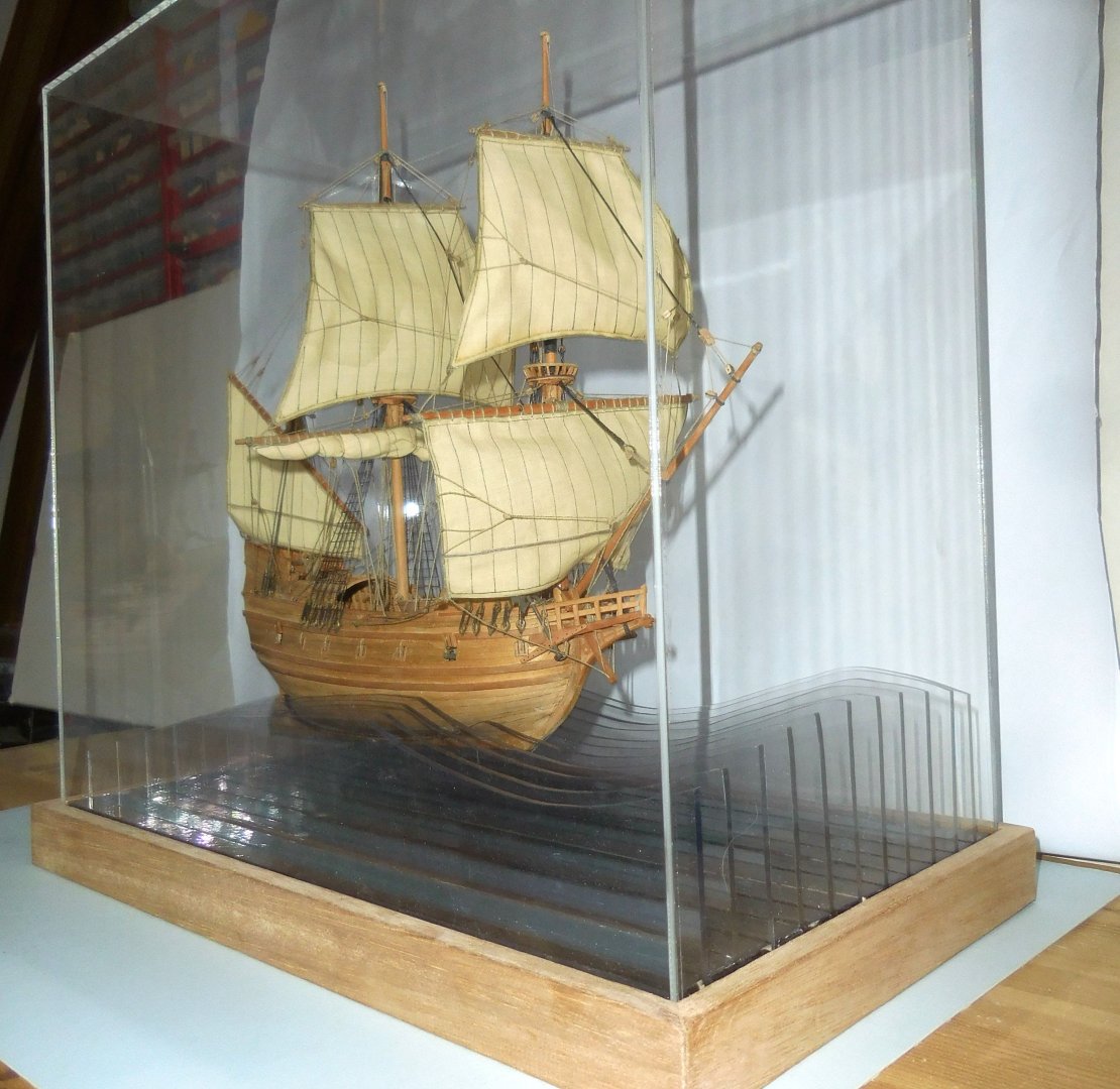
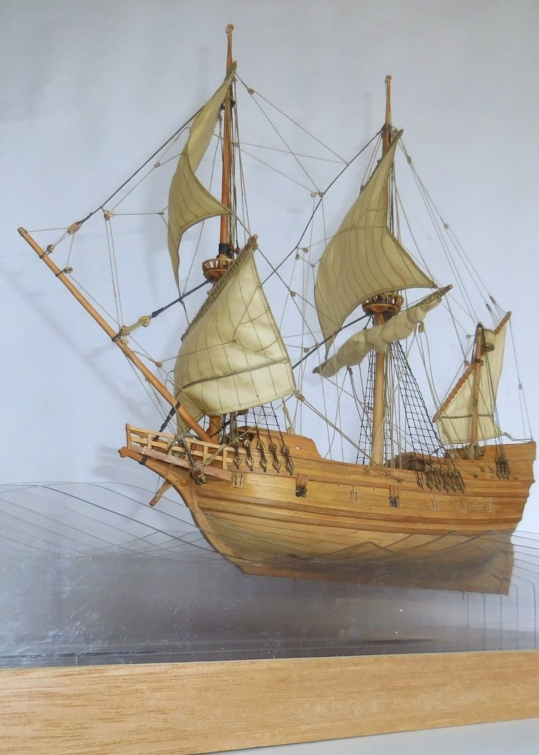
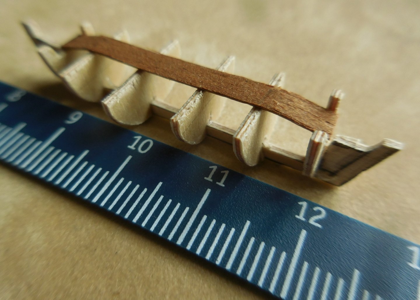
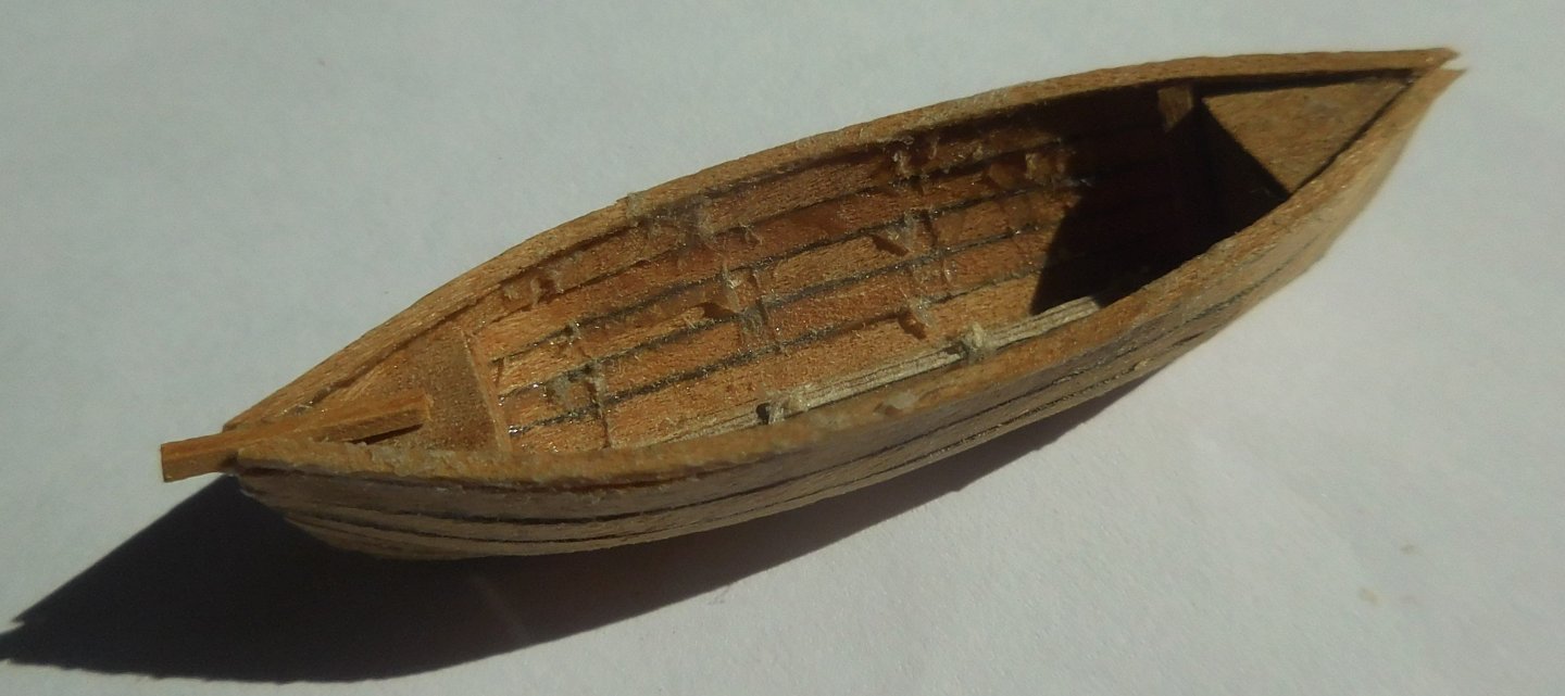
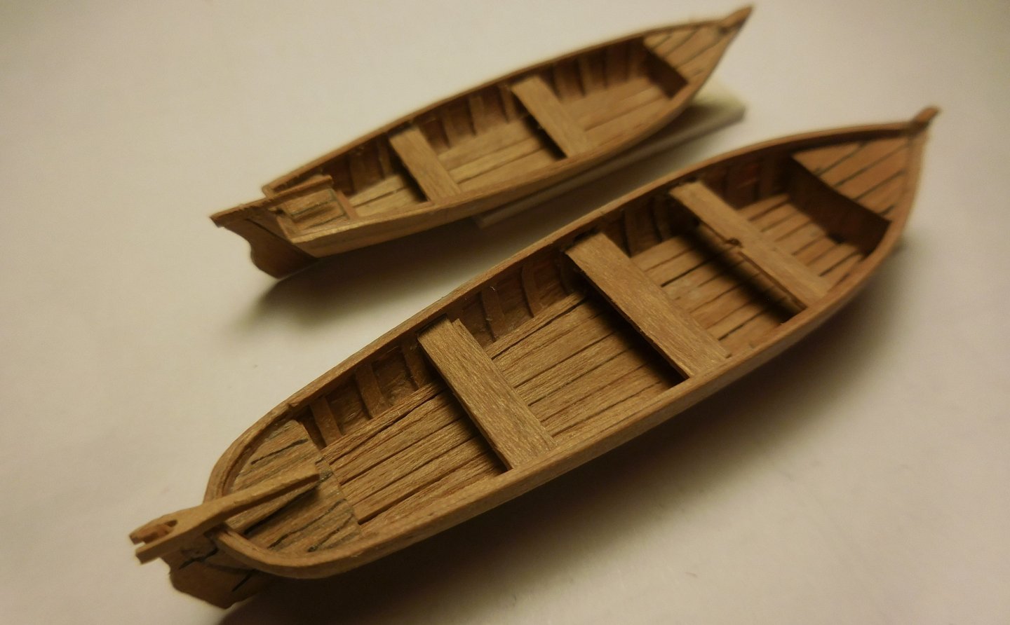
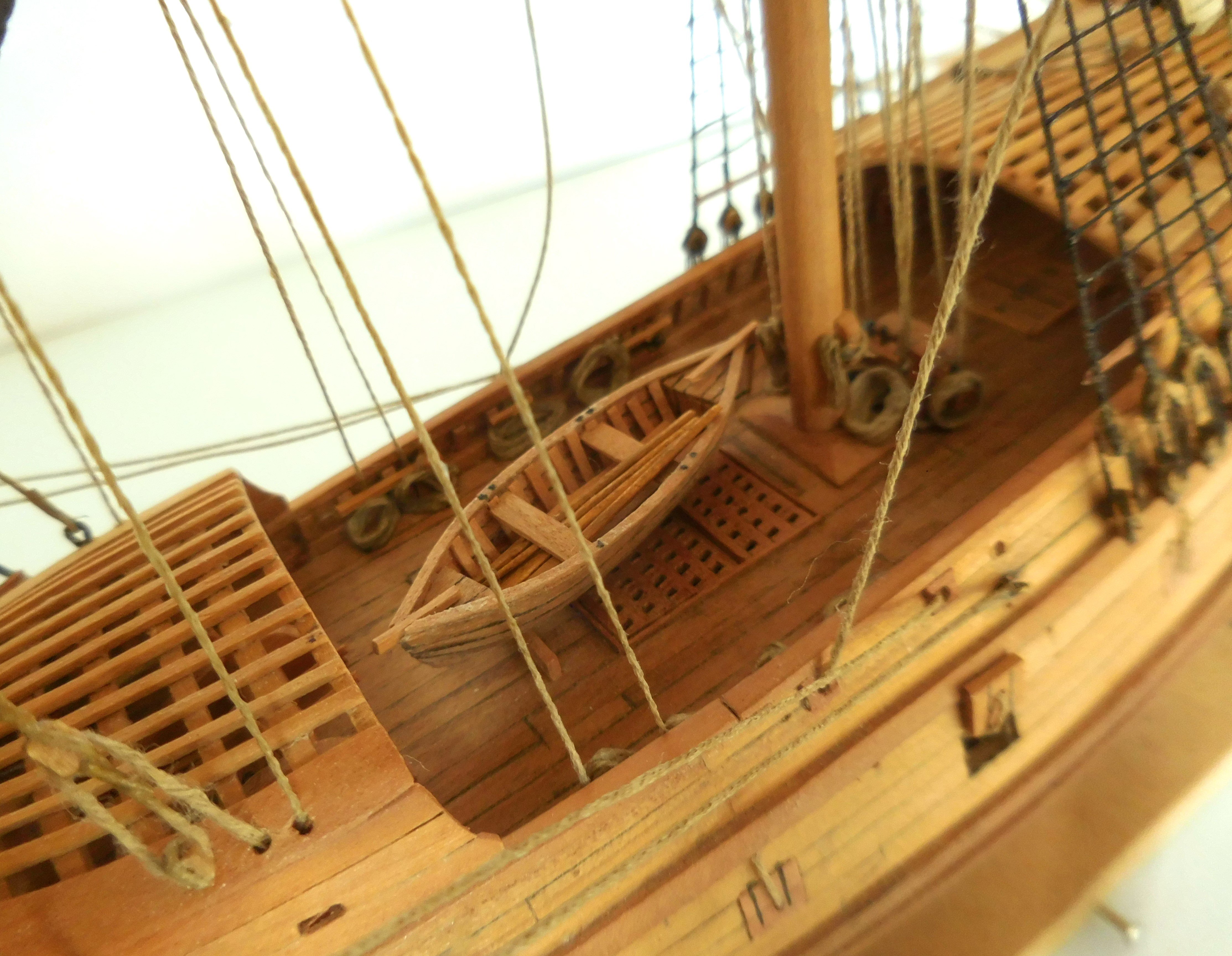
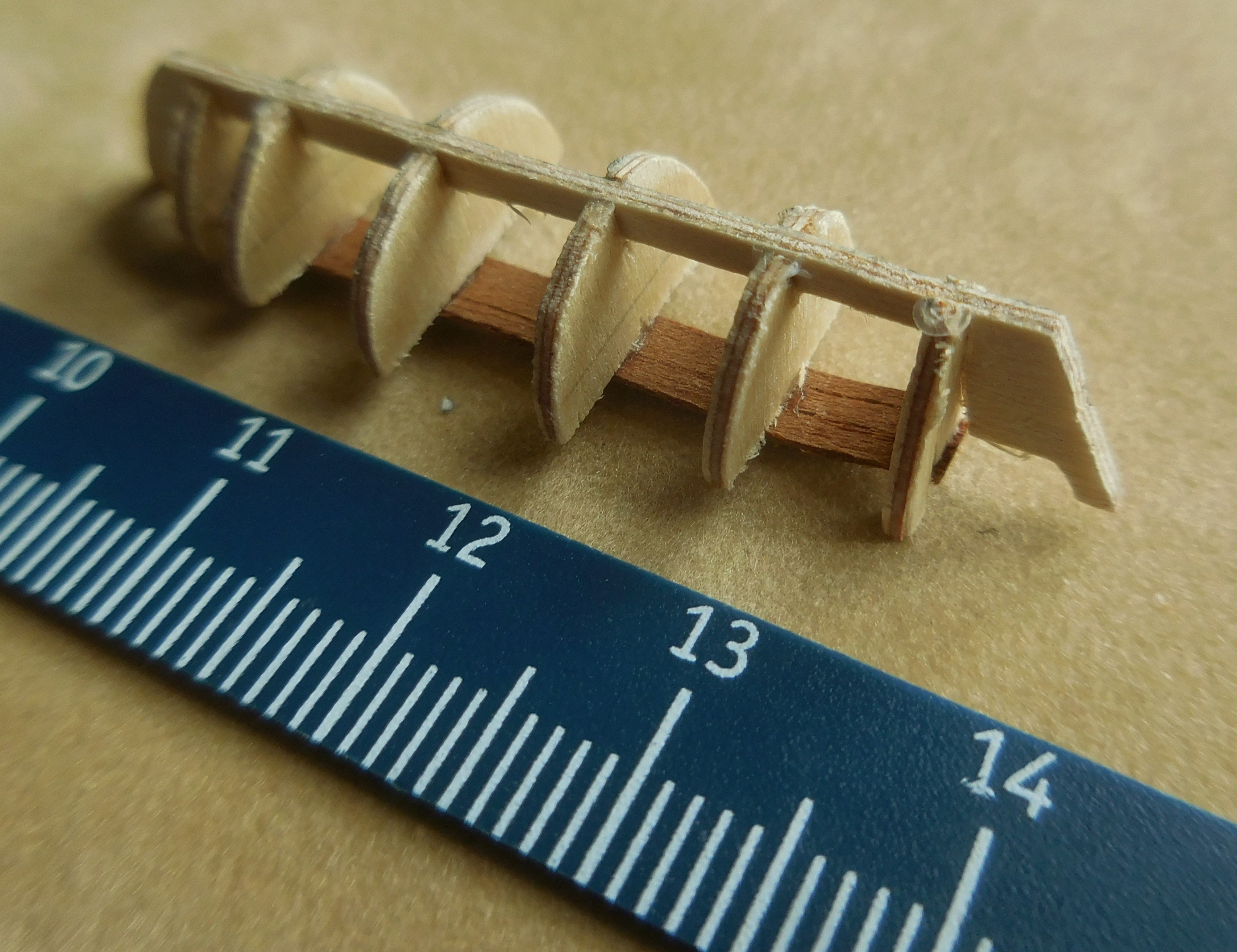
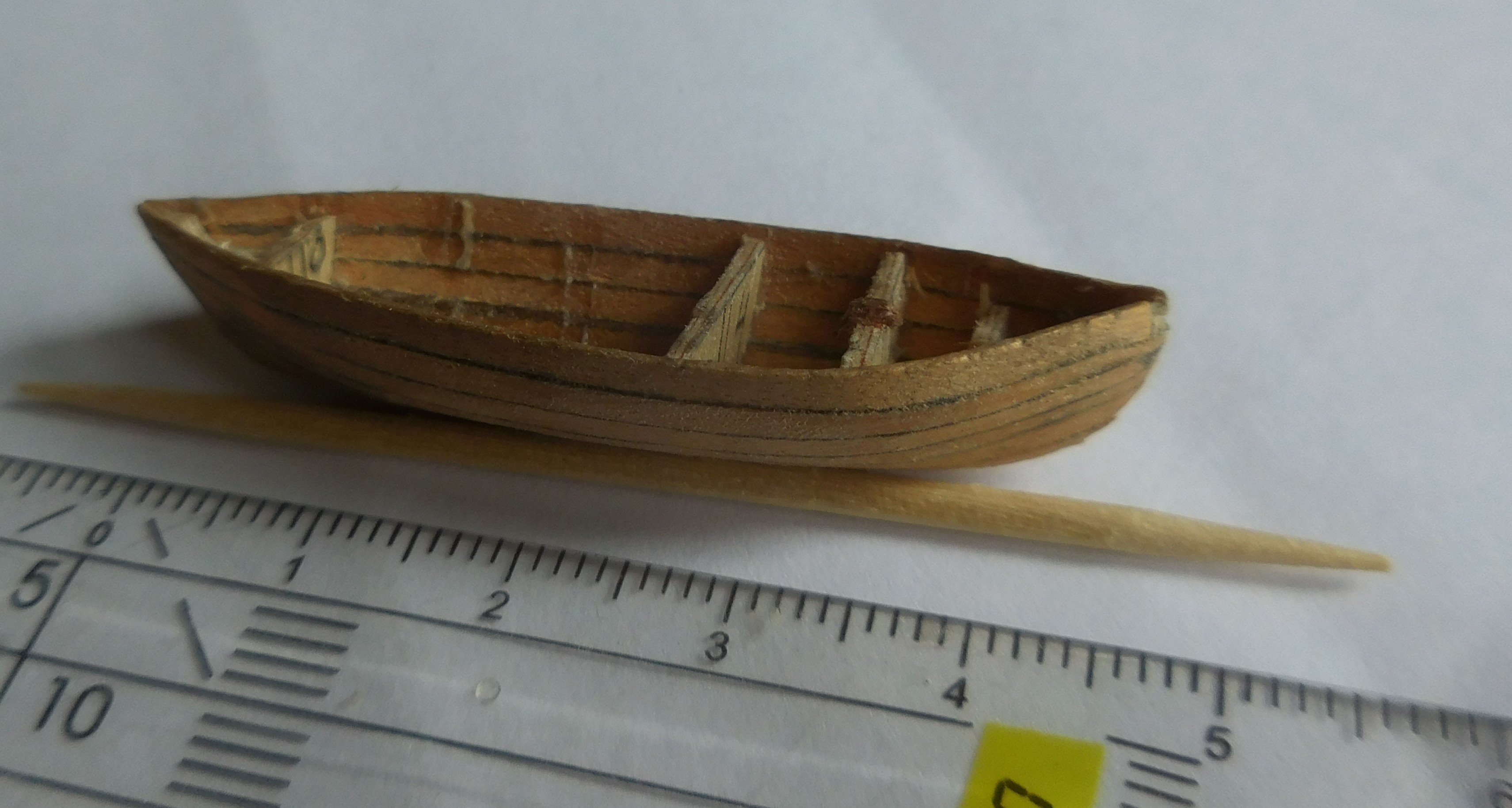
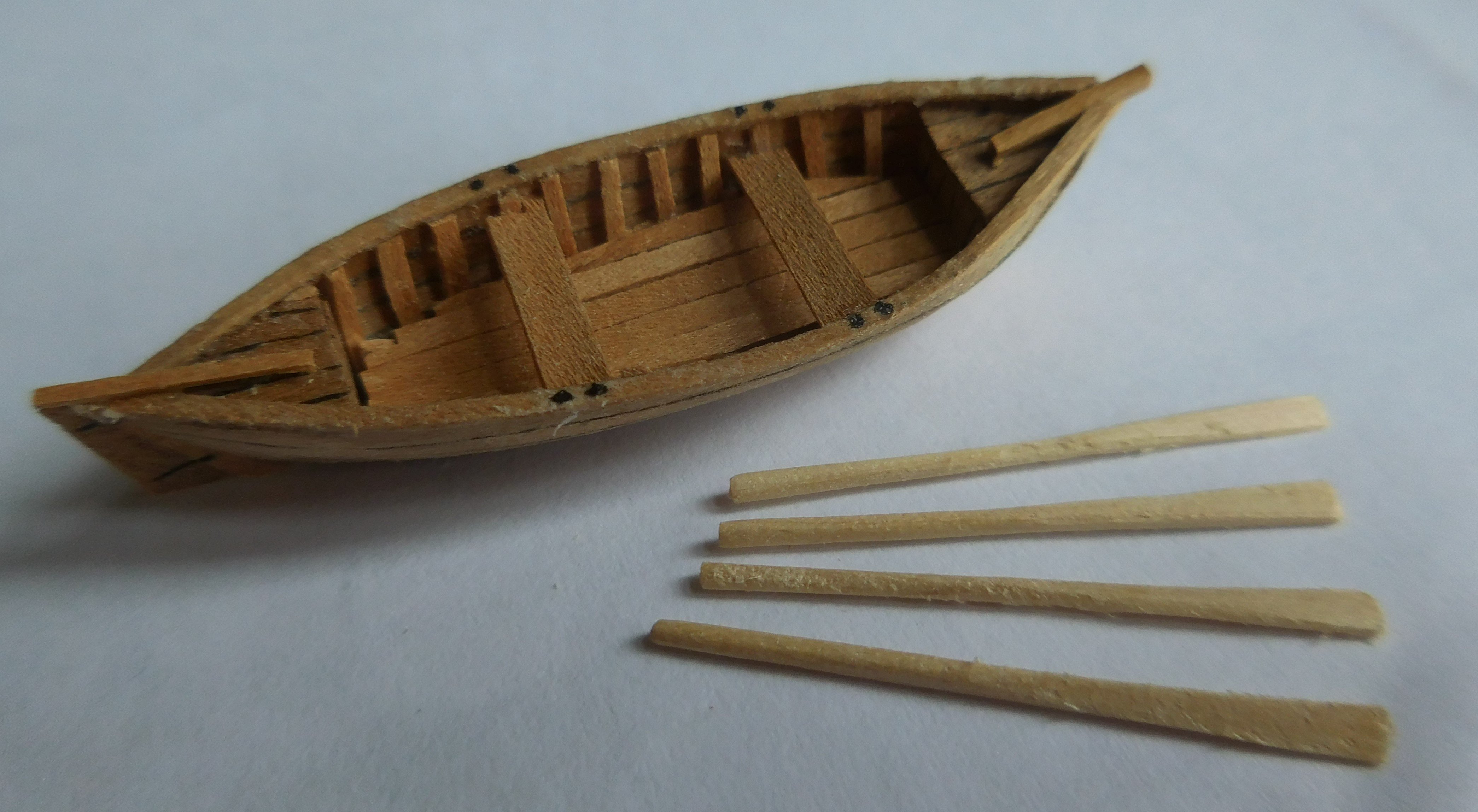
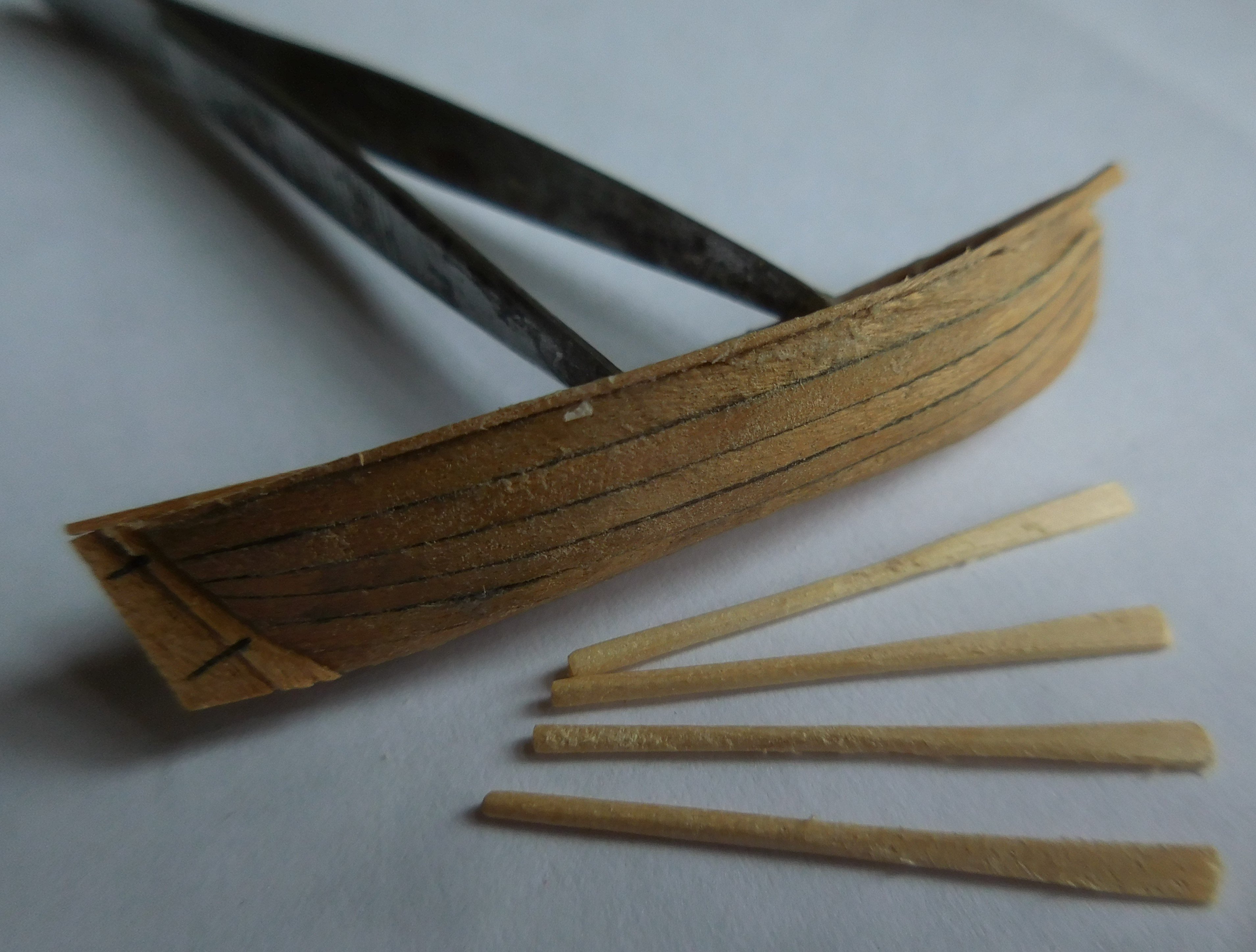
9 The boat. Like most ships at the time, a pinas also had a boat. It is often claimed that these were towed, but on the open sea in stormy weather they could easily be lost. So usually they were on board, and were only put out when necessary. First I made the trusts out of thin plywood and glued it together. The planks were attached to it of thin ash veneer, after which a few trusses of plywood were very carefully removed from it A fore and a rear deck were then put in, and the last plywood trusses disappeared Finally, the real trusses were glued in and the bottom and rowing benches were installed, as well as the rudder. Finally came the oars, made of very thin toothpicks. By flattening the end with a hammer and providing it with glue, the blades could be formed. The boat has a length of 42 mm. After this, it had to be carefully sanded. I have made several boats for other models before, all on the same scale and on the same construction method. The showcase and stand The model is placed in a glass showcase that was made by a company. At the bottom of it I made a stand consisting of perspex discs. For its construction, see my topic: “Making a “wet” stand for your model” march 19 2024.


-
 tartane reacted to a post in a topic:
Mary Rose by Baker - scale 1/50 - "Your Noblest Shippe"
tartane reacted to a post in a topic:
Mary Rose by Baker - scale 1/50 - "Your Noblest Shippe"
-
tartane reacted to a post in a topic:
Mary Rose by Baker - scale 1/50 - "Your Noblest Shippe"
-
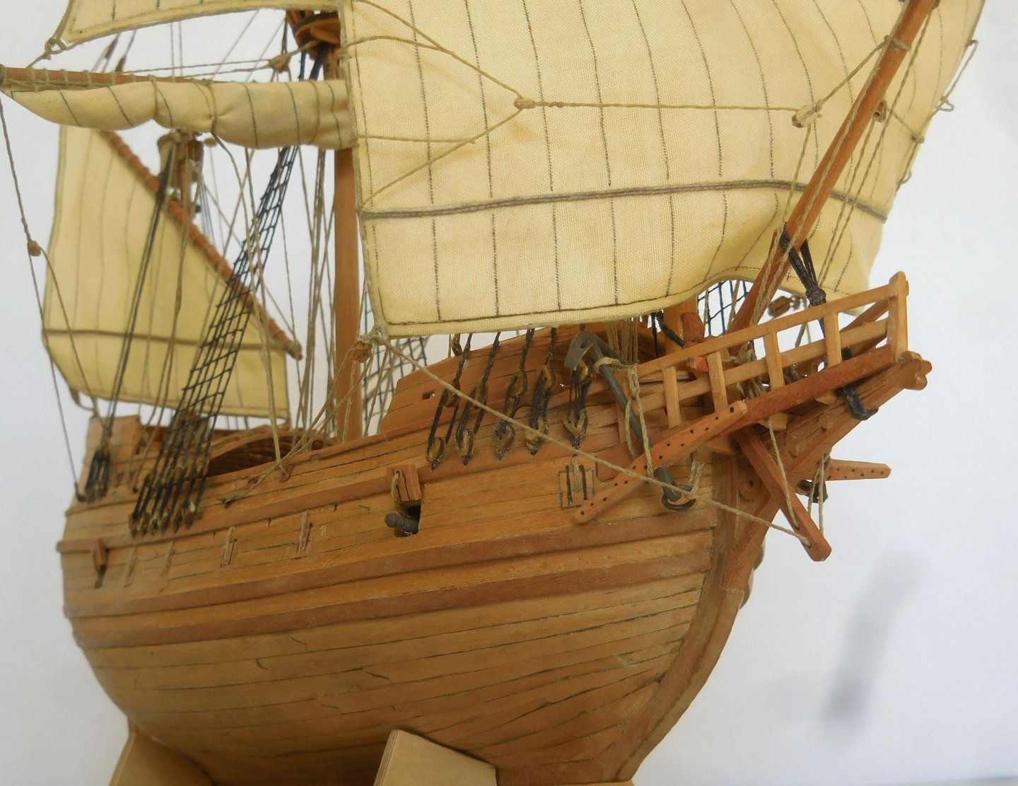
All those images don't convince me. We will have to wait until a wreck is excavated where the fore castle is still visible. At the time that these images were made, it was customary to depict everything more proudly and it was unimportant whether it was correct. See also, for example, the Mataro ship in Rotterdam, where it has been established that it could not sail in that form at all. Constant
-
What I yhink very curious is the enormous height of the fore castle. I can't imagine that a shipbuilder dared to go that high and indeed the ship seems to have tilted as a result. It also catches a huge amount of wind. Isn't the drawing that exists of it a very exaggerated representation of reality? That was often the custom at that time. Wouldn't it be advisable to reconstruct the height to the human scale? So the deck heights do not exceed 170 cm, then with those three decks you get to a height of 510 cm plus the beam thicknesses that were still in between. Then it will be at most 60 cm higher. I would never go higher than 510 cm. But maybe that's also the height you calculated yourself because I don't know the scale exactly. Constant
-
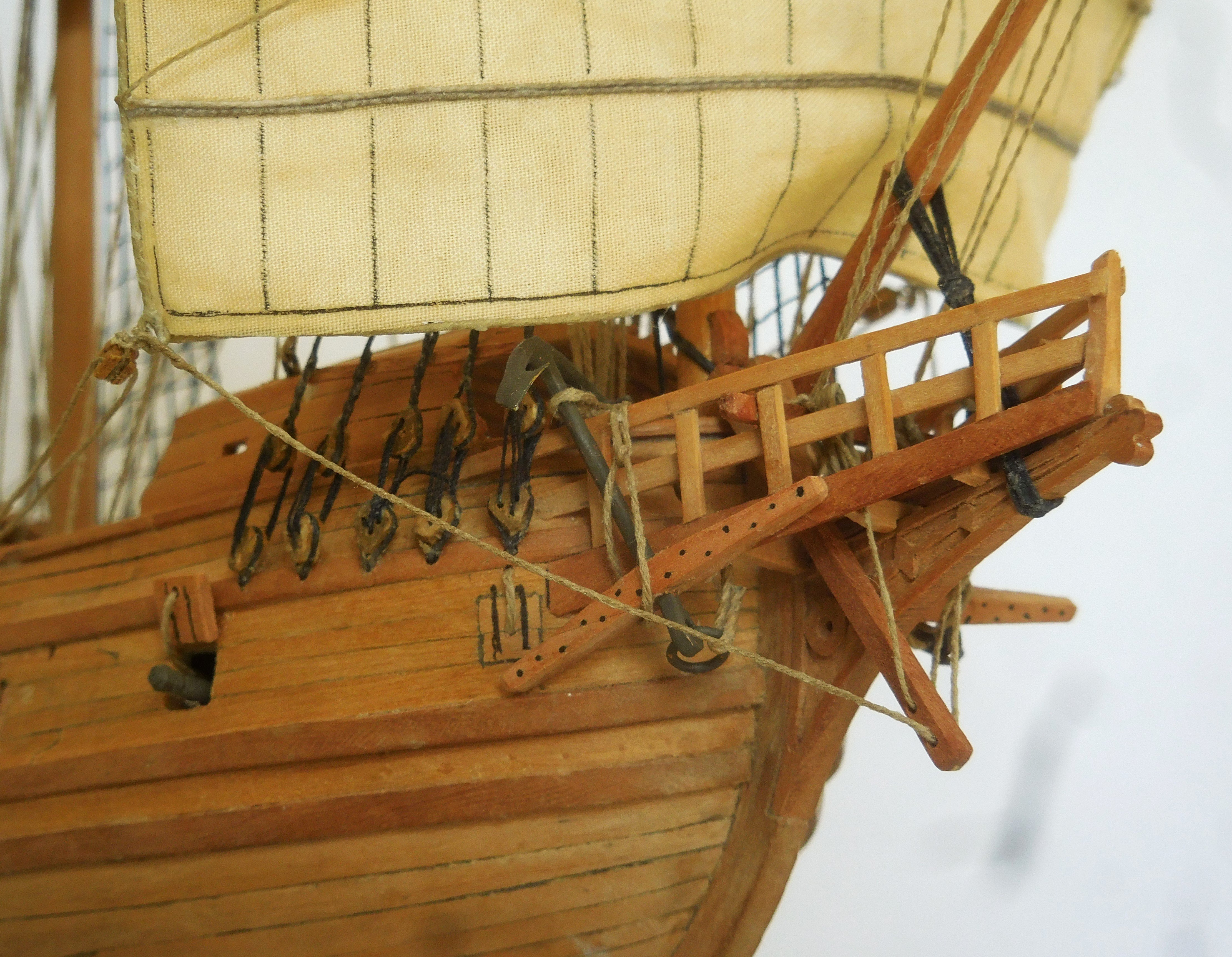
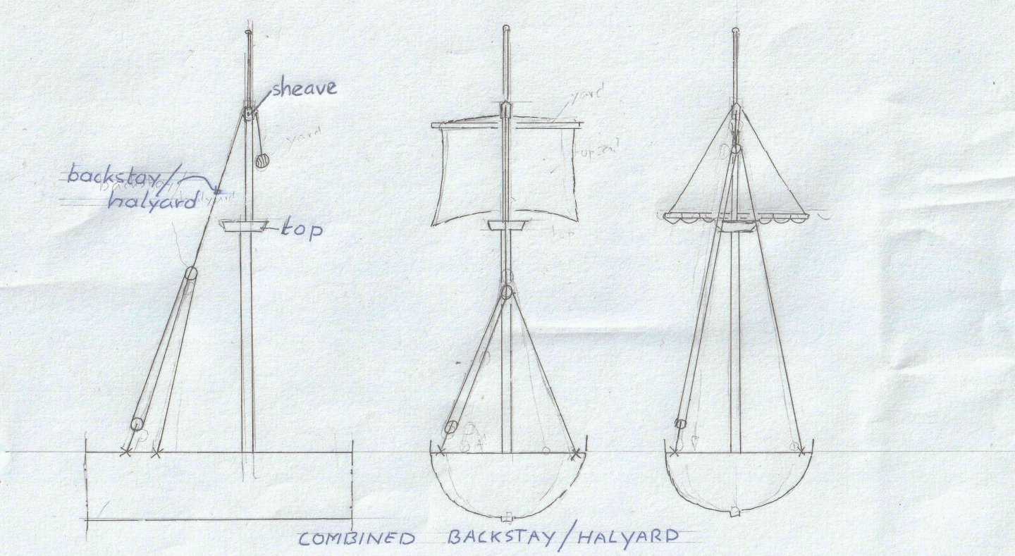
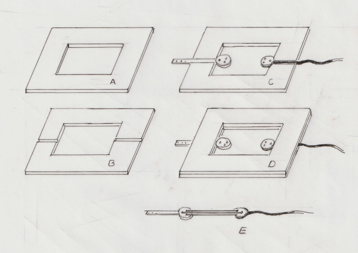
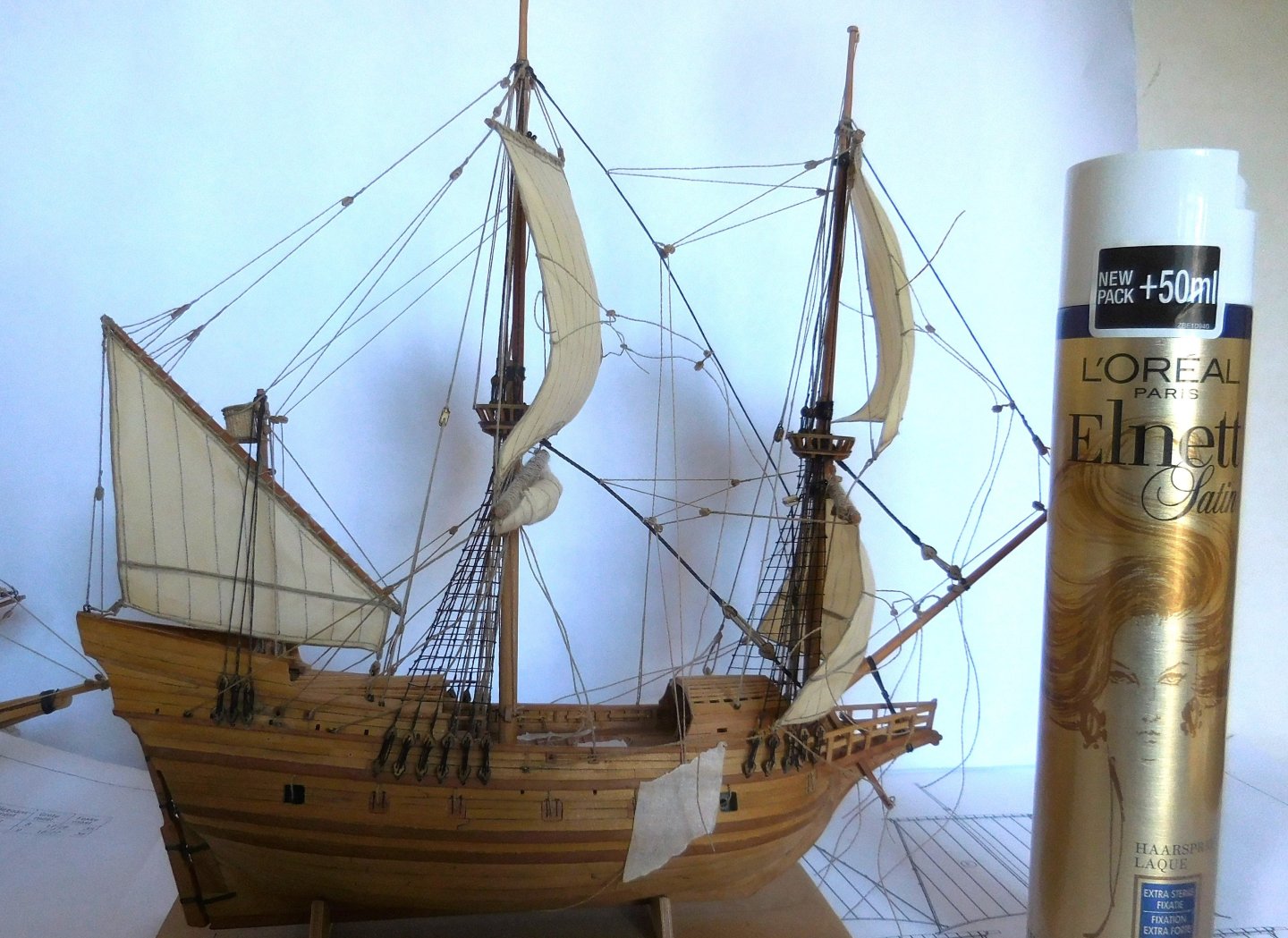
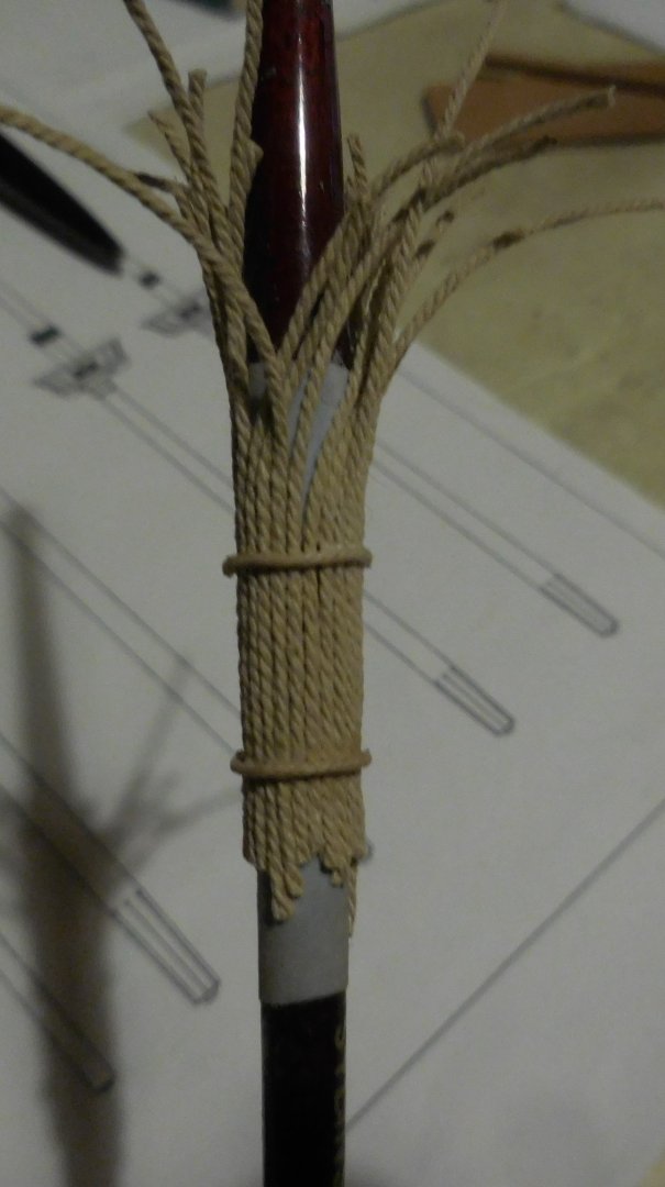
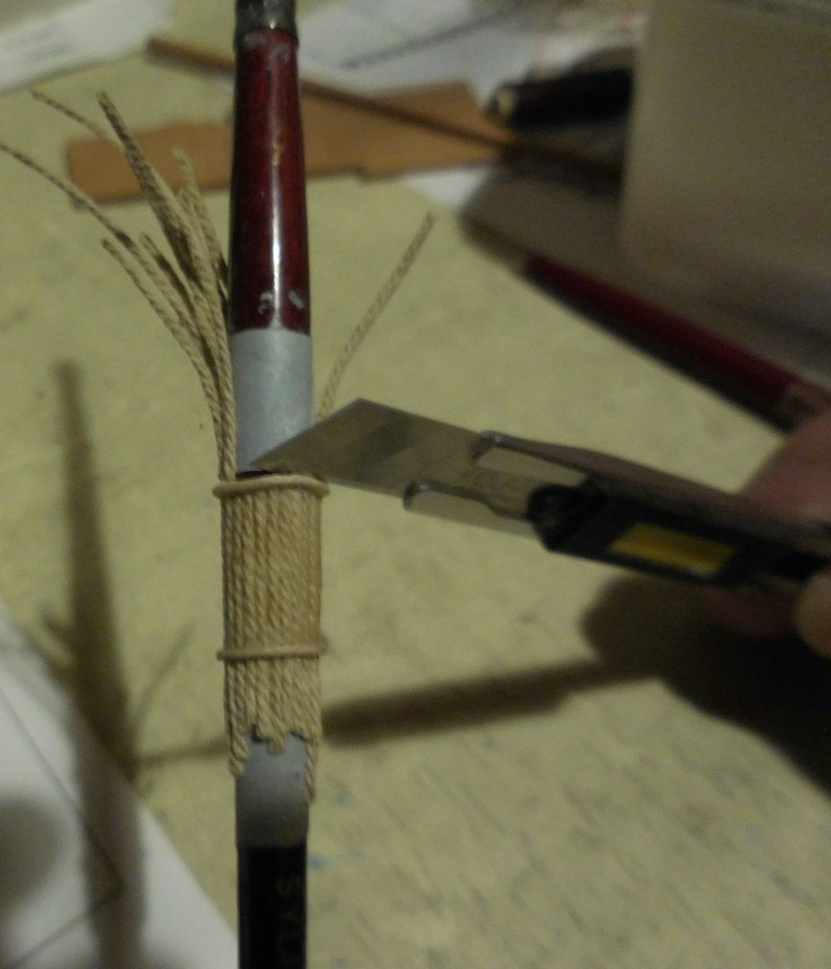
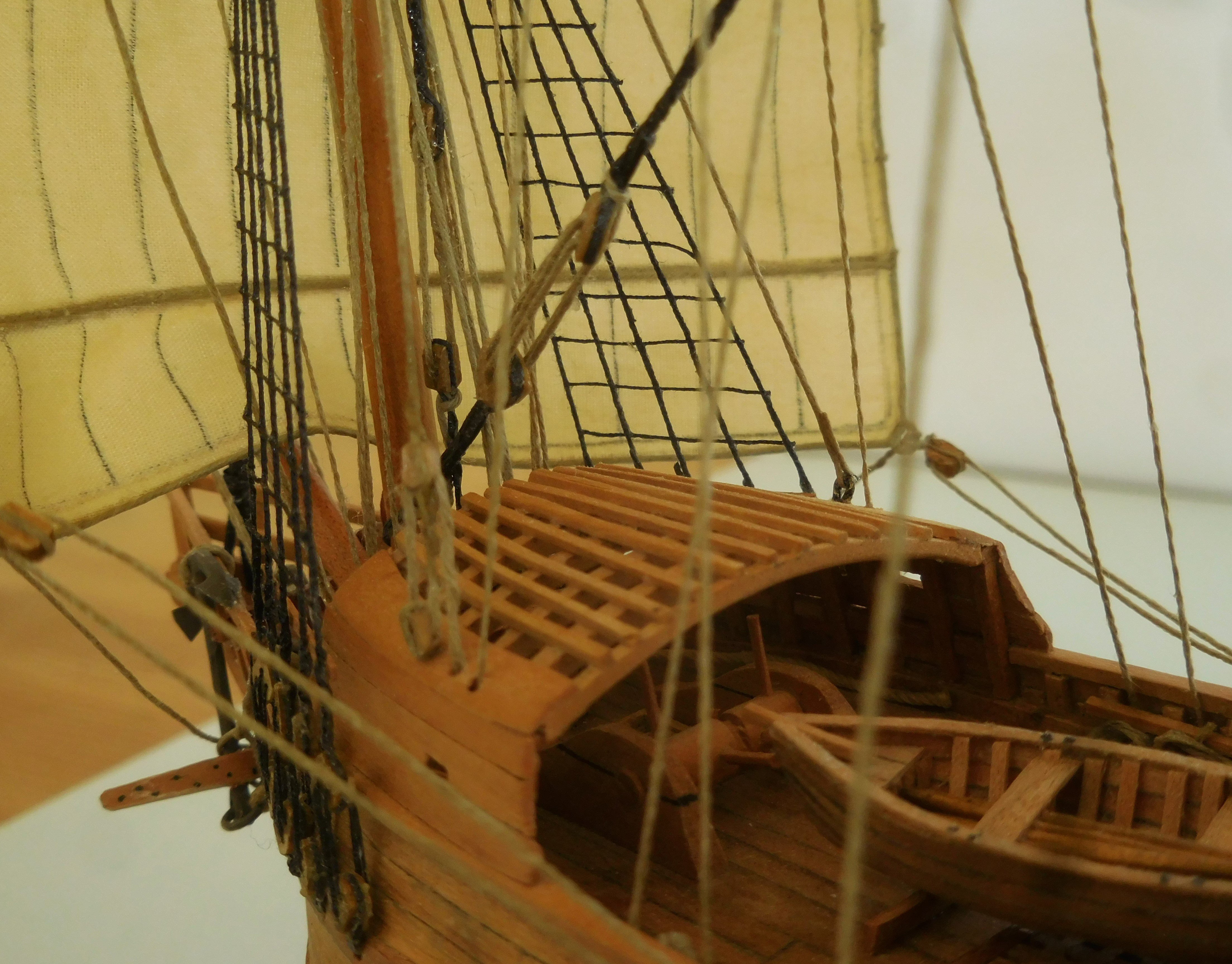
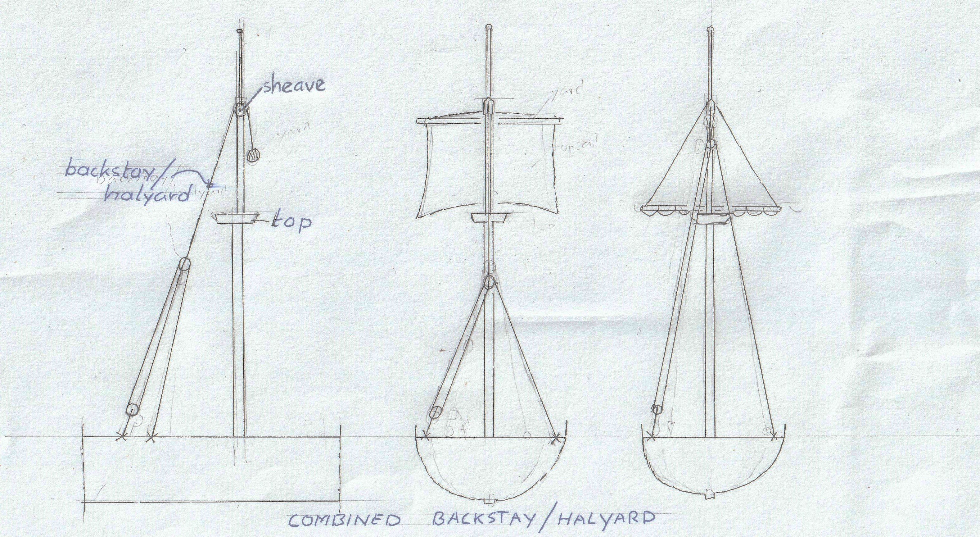
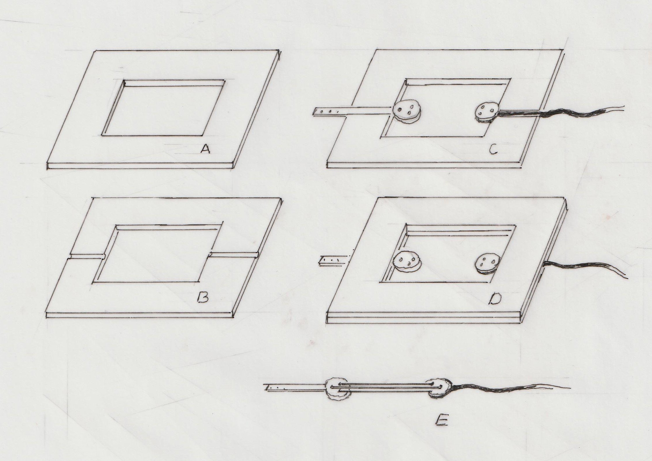
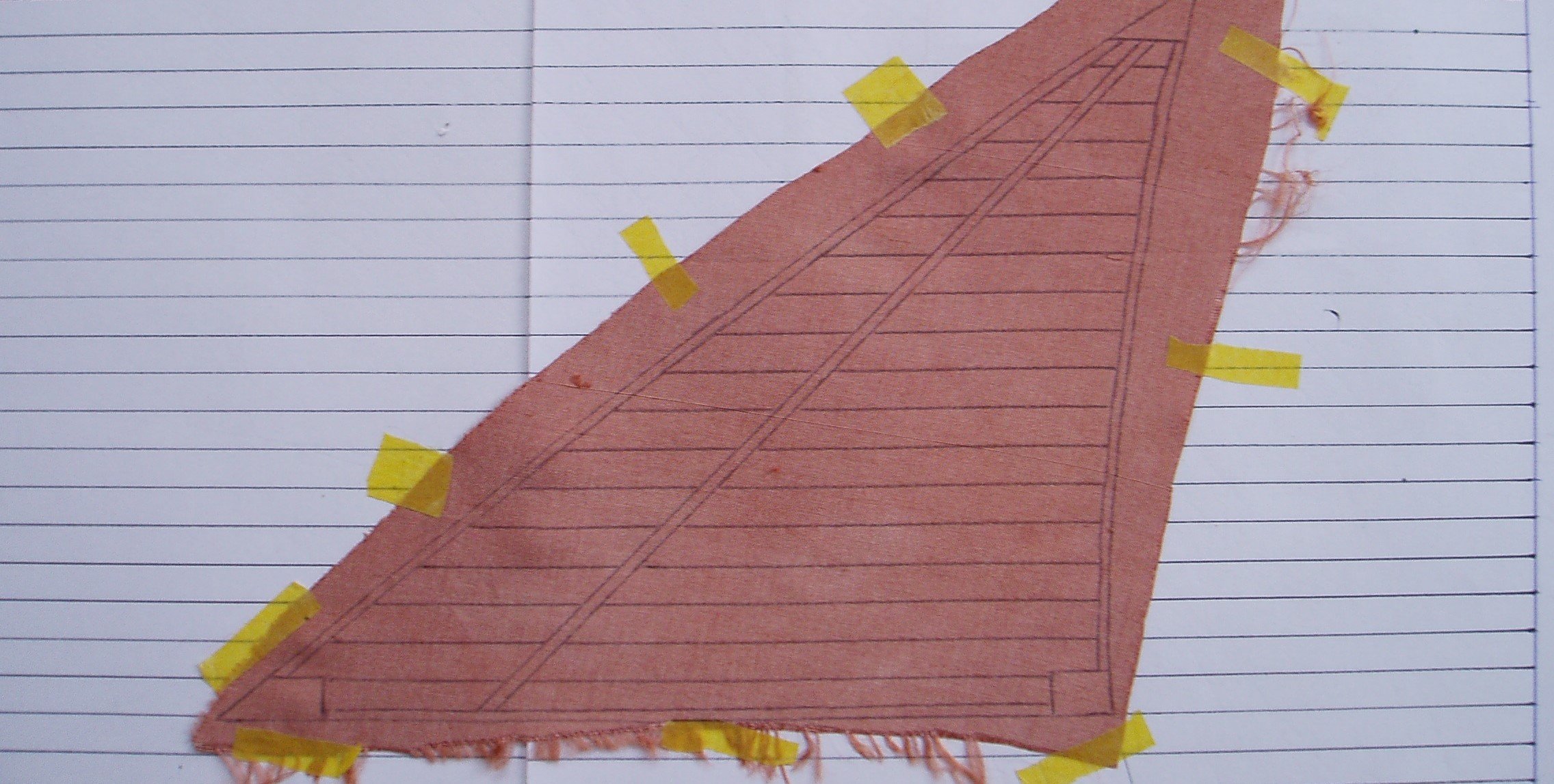
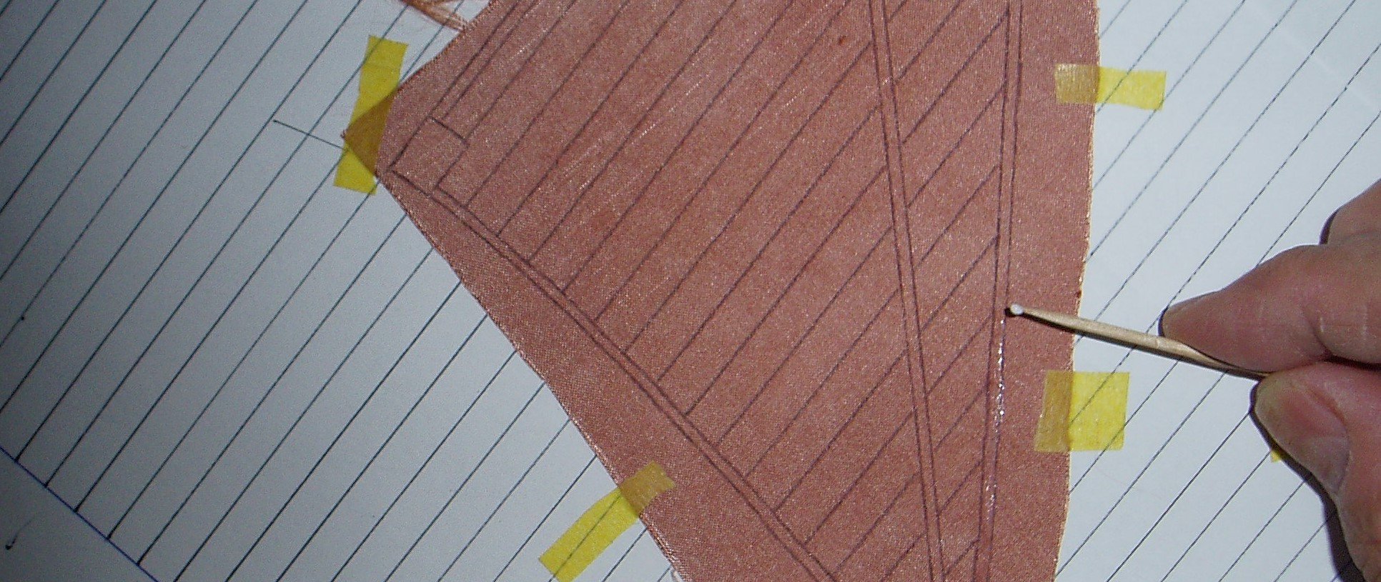
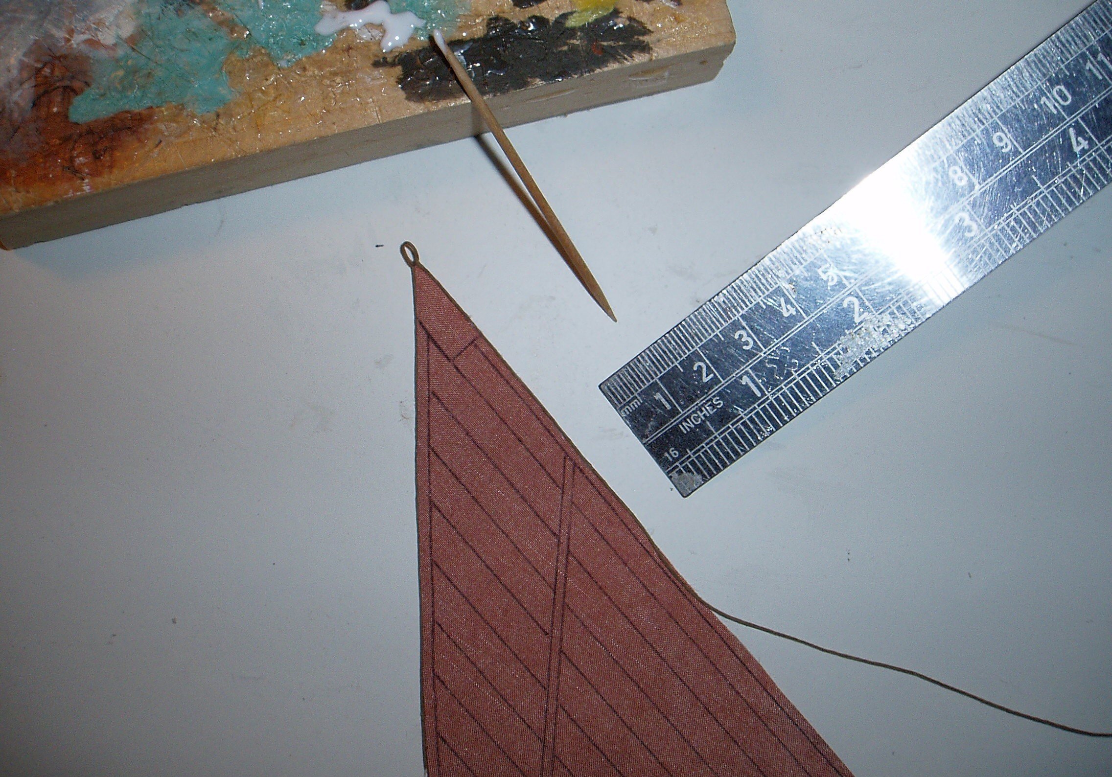
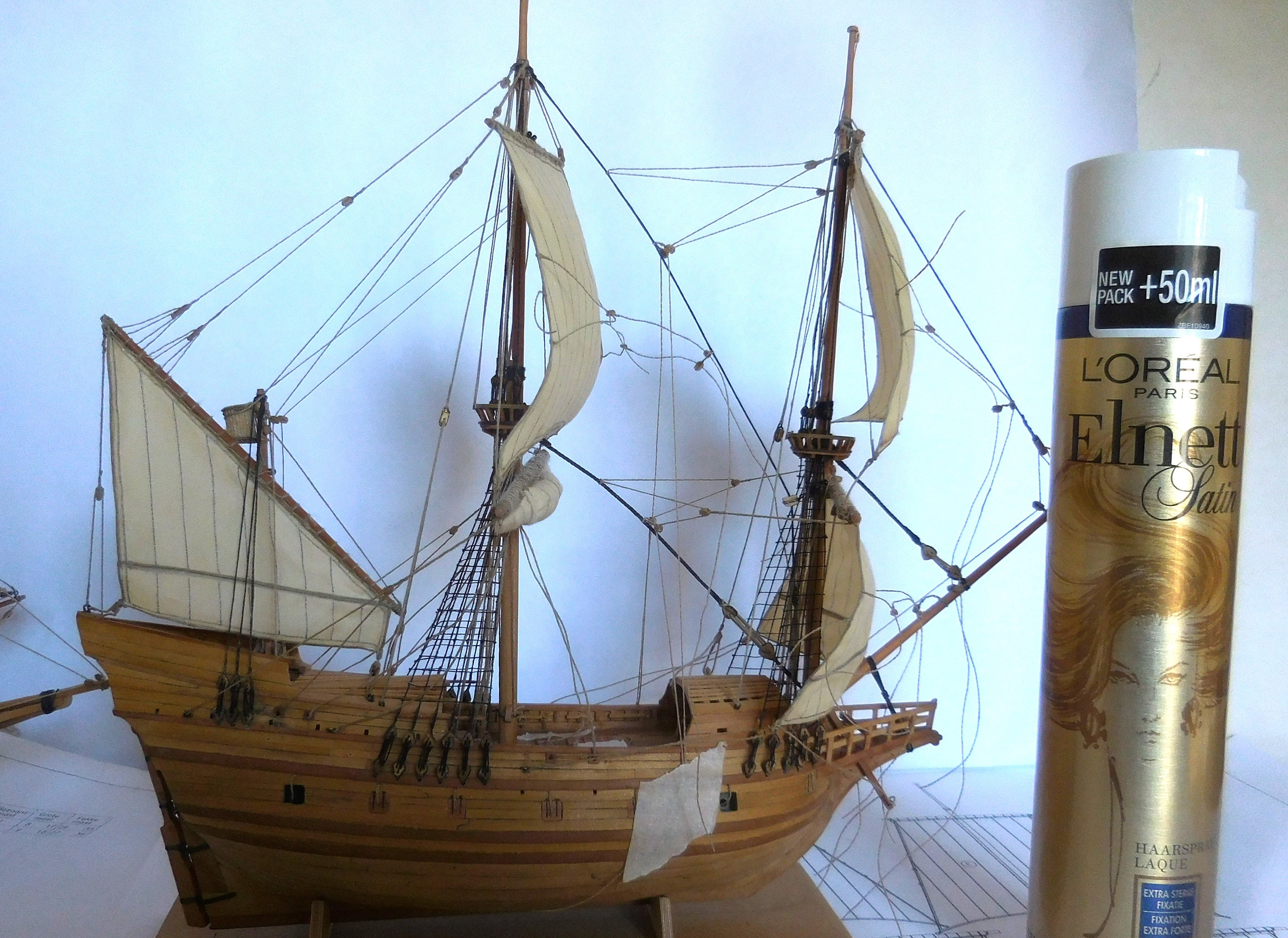
8 The rigging. During rigging, it was a seemingly confusing tangle of wires. This work often caused problems. This is the first square rigged ship I built. The previous ships I made were latin rigged. Their rigging is considerably simpler than the rigging of this ship and is also completely different. The lower yards were lowered onto the railing, the rahout. This was no longer done in the 17th century, where the sails were tied to the yards just below the tops. The upper yards were lowered onto the tops. On the model the mainsail on the mainmast is tied up, which was done at deck height and then the yard was hoisted up to below the top. Since the 17th century, in order to moor the masts at a great height to prevent them from bending forward, the masts have had back stays, which were attached on the deck. On this ship, the back stays and the halyards for hoisting the topyards are still combined into one rope. Exactly how this worked is not entirely clear. Ab Hoving left it entirely up to me to find a solution. The topyards were hoisted from the top. This is only possible with a haliard and a sheave in the mast. The halyard was fitted with a block and tacle was attached to port and starboard. Once the yard was hoisted, it automatically became a backstay, a rope that held the top of the mast in place at the back to prevent it from bending. So this is a possibility as it could have been made. On large ships after 1600 it can be seen that there were ratlines on the shrouds everywhere. On ships before 1600, there are only four shrouds with ratlines. Only from the deck to the tops of the foremast and mainmast. This can also be seen in the drawings of Gerrit de Veer. These were attached about 40 cm apart. I glued the ratlines to the shrouds with superglue. In fact, all the ropes on the model were far too thin compared to the rope available in model shops. This meant that the available rope had to be split again and again. This also meant that different thicknesses of rope had to be made. I only used rope that had absolutely no plastic in it. This rope is not stretchable and can also be glued very well with wood glue. In addition, each piece of rope was pre-glued to prevent the fibers of the rope from sticking out and thus not attracting dust. The running rigging was made of brown rope, the standing rigging was made black (tarred). The smallest commercially available blocks had to be purchased. It became a search on the internet for the various suppliers. A number of blocks had to be made even smaller, which could be done by cutting and filing. The smallest blocks are located in the tops of the masts, in fact the blocks that were needed to hoist the flags. Some blocks were composed like the blocks at the ends of the yards. These were created after gluing two blocks together. Some of the blocks had a somewhat different shape, like the lift at the top of the mizzen yard. The first blocks from the tops that are needed for the lifts of the yards are also different. They had to be made manually from a piece of wood. I avoided to place round deadeyes. At that time, the deadeyes were triangular in shape. I filed round deadeyes in the right shape. Making deadeyes and lanyards Usually on shipmodels the deadeyes and lanyards are made when the lower deadeyes are already mounted. Because the scale of this ship is very small, I made the deadeyes and lanyards separately with the accompanying shrouds. I designed the following method: I sawed two equal sheets of plywood 2 mm thick with the same rectangular hole in the middle (A and B). The length of this hole is the length that corresponds to the total size of deadeyes with lanyards. In the sheed B, two grooves come next to each other. The chain plate will be attached to one deadeye and the shroud will be attached to a second deadeye. Both blocks are now placed in the grooves, picture C. On top of that comes the sheet without grooves, picture D. Both plates can now temporarily attached to each other with tape. Inside the opening, the threading can now begin and be secured. After removing the tape, the ready-made deadeyes with lanyards appear (E). They can now be attached to the model. There are 38 deadeyes with lanyards of two different lengths attached to the model. So that requires sawing the plates twice again. This ship was not yet equipped with channels, that only came a few years later. The chain plates, possibly ordinary rope, were attached to the a wale. Here I chose the method of replacing the chain plates with rope. It took quite a bit of effort to get the thin strings through the tiny holes of the blocks. Often these passages still had to be drilled out with very small drills. The end of such a rope was reinforced with some superglue so that a thin sharp needle was created that could easily go through the hole. The sails. The sails were made of cotton that was as thin as possible. It was difficult to get to a fabric store there, so I went to a second hand store and dived between the women's blouses hung there. After some searching, under the hilarity of ladies present, and comparing, I found the thinnest possible white cotton that I was going to use for the sails. The dimensions of the sails were copied from the drawings and coloured The pattern of the strips was applied by means of a Rotring pin. To imitate the bolt-rope on the sails, I glue rope against the side. I always use this method when making the sails of my models. The photo shows how this works (on the sails of a chebec). I use regular wood glue. The edges of the sails are first provided with highly diluted glue, which should not shine after drying. So first make test pieces until the glue is so diluted that the shine is gone. Apply the glue with a toothpick After drying the glue, the outline must be carefully cut out, the glue will prevent the fabric from fraying The pre-glued rope is then glued to it in pieces of about 30 mm by pressing it with a metal plate, for example a steel ruler. See also my website; www.constantwillems.nl After most of the rigging and the sails were attached, I wanted to make a natural bulge of the sails. With a fan I blew the sails into a nice position and then added hairspray with a spray can. After some time I stopped with the fan and the sails remained in a natural position.
.thumb.JPG.0c8b1ee91105688e1cdc9787c3393761.JPG)

-kopie.thumb.JPG.7e095a1306d20b0e14d8842d89bf13c0.JPG)


.thumb.JPG.711b863b39c3b48814ef2807e7782772.JPG)
-
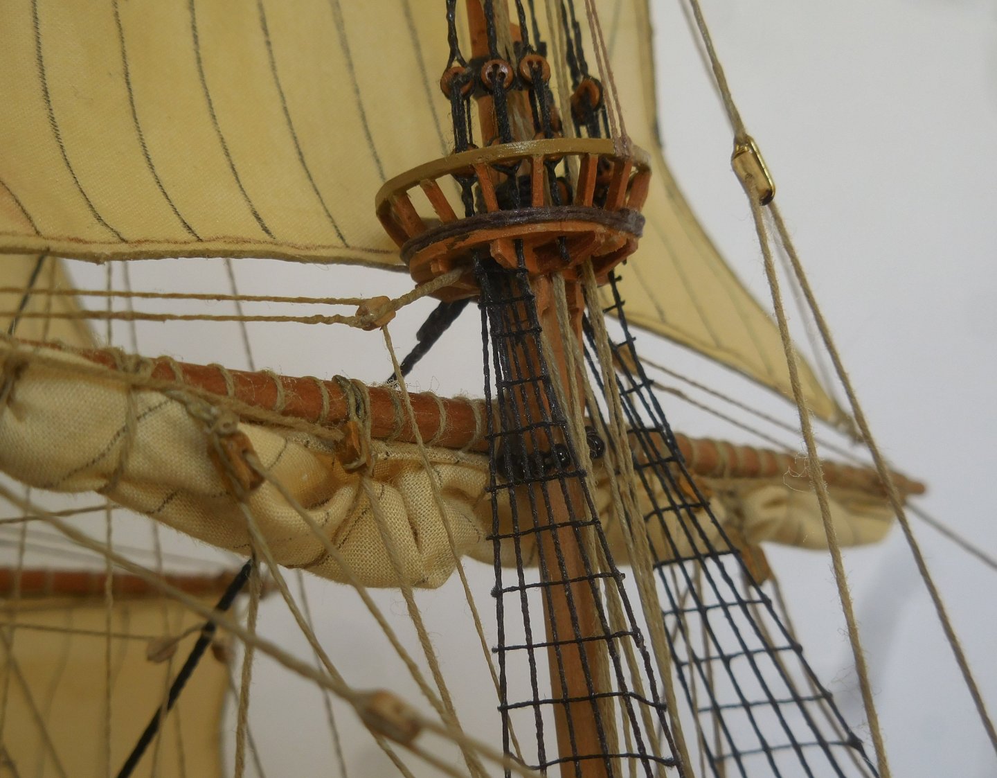
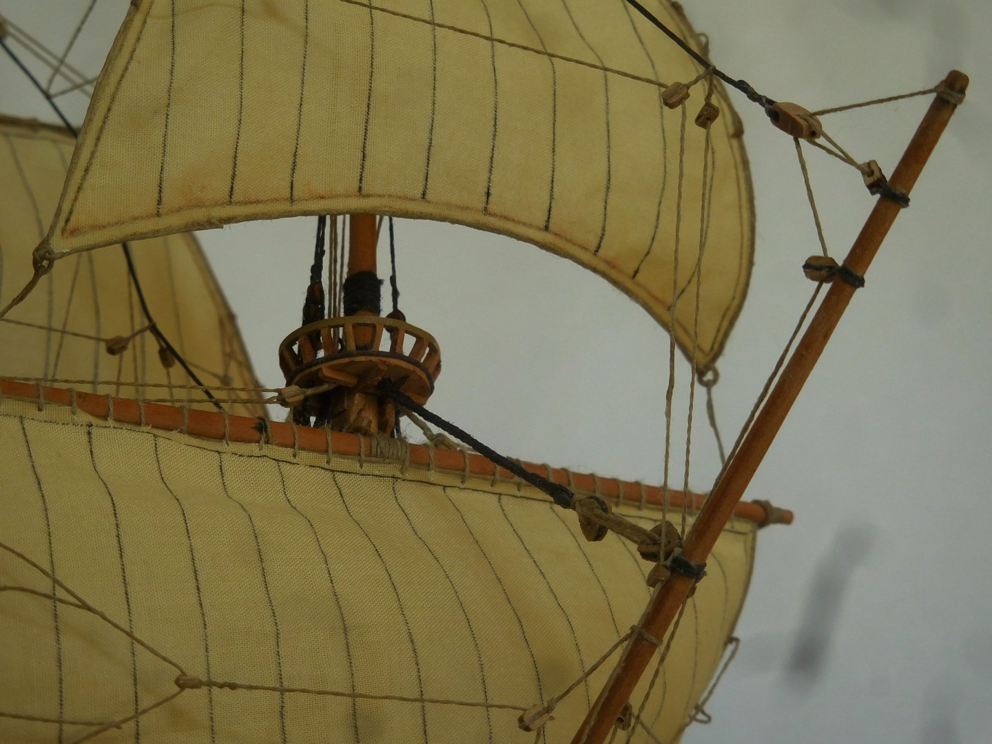
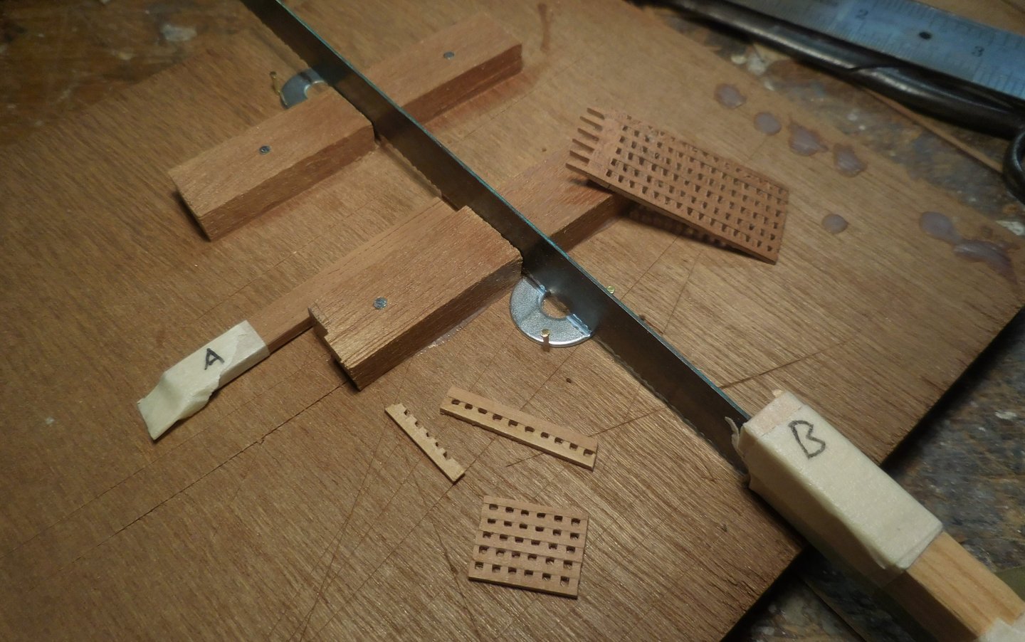
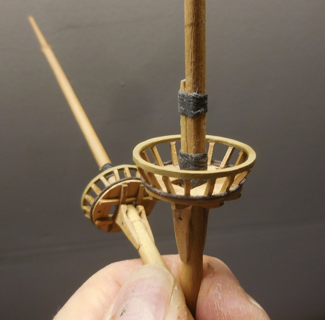
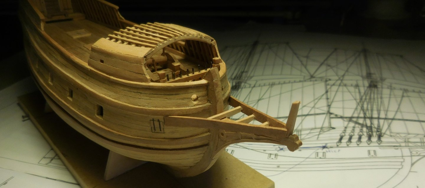
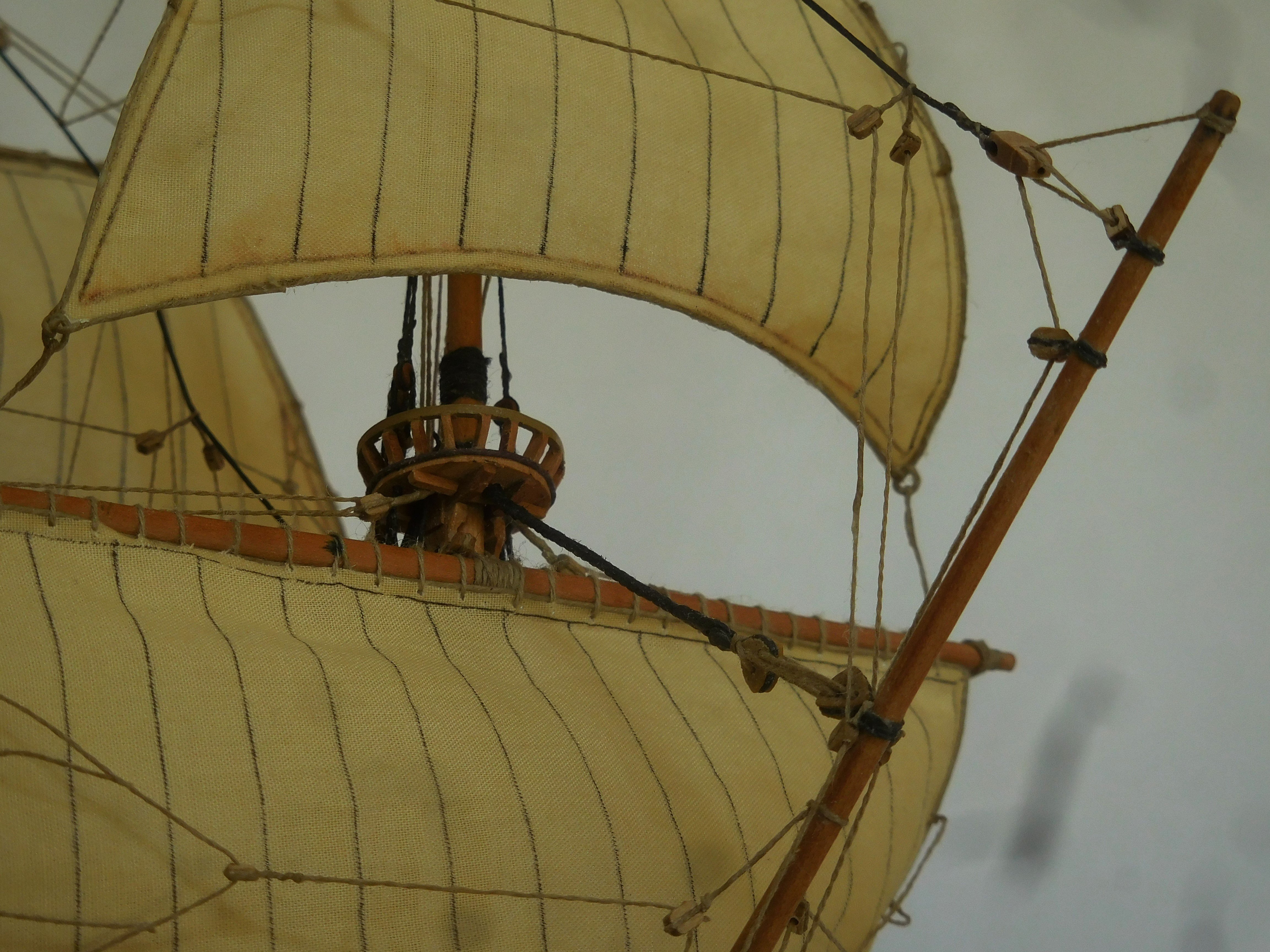
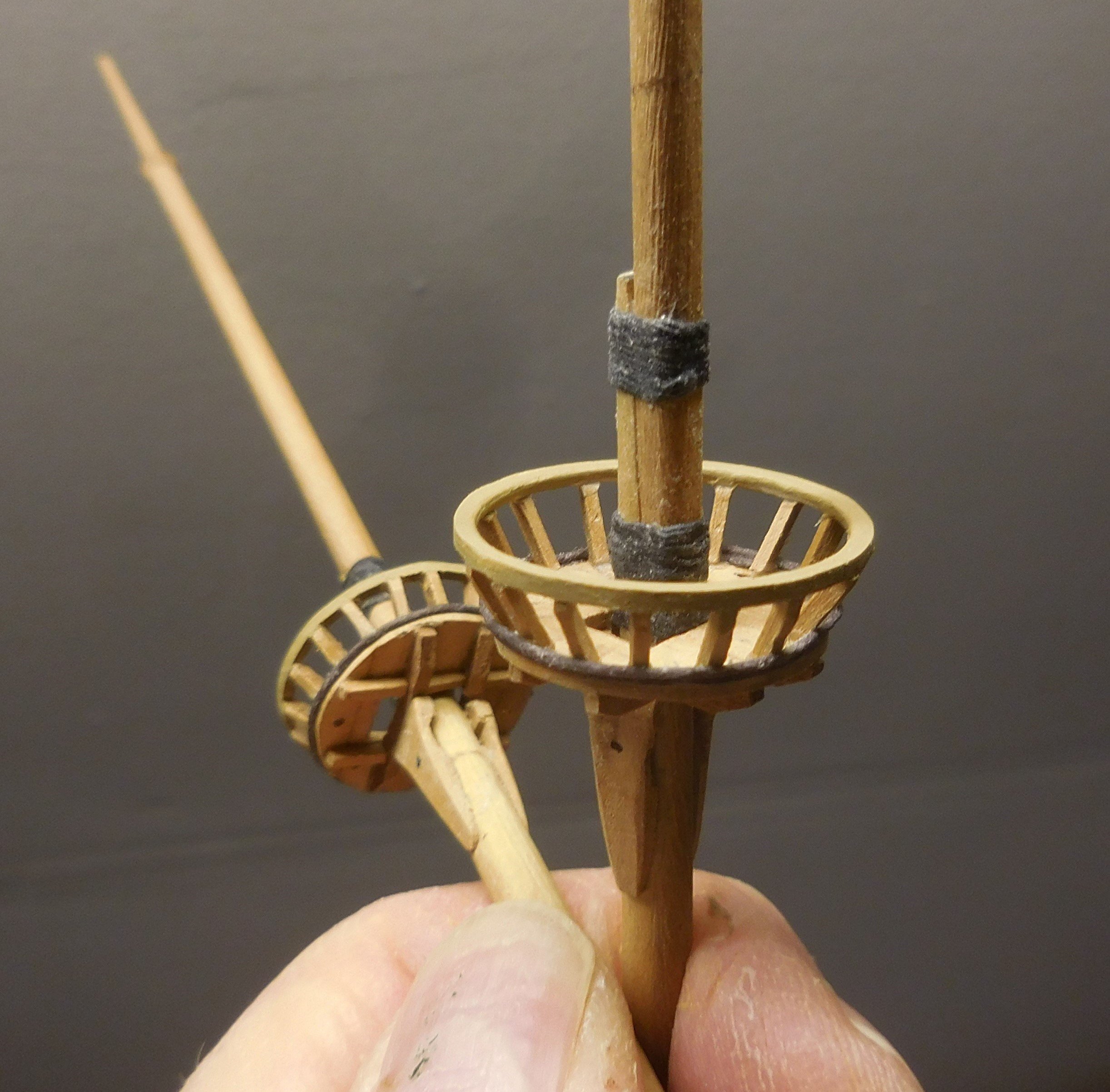
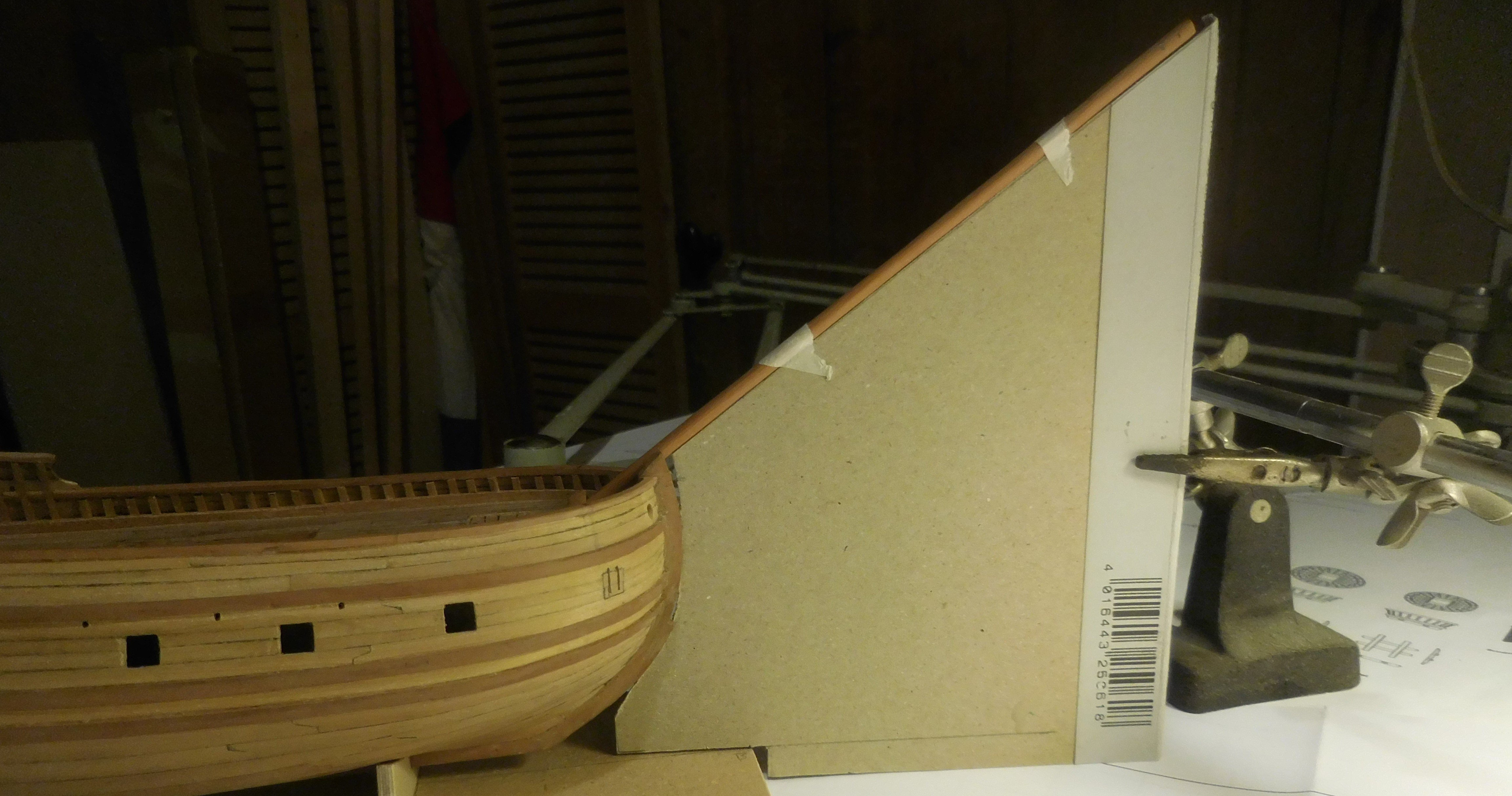
7 Hatches with gratings. The ship has two hatches with gratings, both of which are located amidships, separated by an intermediate beam. B is the blue blade of a large hacksaw, with a slat to protect my fingers. That saw has a thickness of just under 1 mm, which can be used to make a trench of width converted to the scale 1 : 87 is .7,5 cm The holes in a grating should never be larger than 7.5 cm, otherwise the crew will break their ankles when they walk over them. I made a guide through which I slided a bundle of slats (A) of 2.5 x 0.8 mm. Slots were then carefully sawn in them that neatly stop at the thickness of the two metal rings that are under the saw. If a little too much is sawn away on those rings, I could turn those rings in a different position In this way, thin planks with slots are created, which glued together, form a grid. The masts, bowsprit and the yards. Nowadays we know almost everything about the rigging and masts of the ships after 1600. This is only partly the case with ships from before that time, to which this ship also belongs. For that reason, a few things had to be thought of myself, as if I were in the shoes of the skipper at the time. These will be discussed in the course of the story. The foremast and the mainmast are keel-stepped, the mizzenmast stops in the deck above the tiller. The mizzen mast is in fact pulled backwards when the shrouds are attached, because this type from before 1600 did not use a mizzenstay. This mast had to be supported backwards. I solved this by putting a wooden bobbin between the mast and the front of the cabin. The three masts, the yards and the bowsprit are made of pear wood, cut and filed to the right thicknesses and tapered. On 17th century ships, it was customary to make the topmasts extendable, a novelty that was applied at the end of the 16th century. This ship may have had sewn topmasts on the foremast and the mainmast. However, the replica that was built in Harlingen, and was completed in 2023, has extendable topmasts. The connection between the mast and the top mast is not extendable. The angle of the bowsprit in relation to the waterline was accurately transferred to a piece of cardboard, after which the bowsprit was glued into the hole and support provided for this purpose. In the photo above, the lack of the mizzenstay is clearly visible. Apparently, a basket was attached to the top of the mizzenmast, which can be seen in the drawings of Gerrit de Veer. I made the basket by attaching glued rope to a plastic pen, a ballpoint pen. Above and below the basket, the pen was covered with double-sided tape, to keep the ropes in place. After drying, the basket could be cut loose and a bottom, also made of rope, was added. On the drawings of Gerrit de Veer it is not clearly visible whether a gammoning has been applied between the bowsprit and the head knee. In order to relieve the pull on the bowsprit upwards, this seems to be necessary, as later ships in particular show. In any case, I applied it, just like with the replica in Harlingen.

.thumb.JPG.72feebe3af52597d4cd57ddcbaaa938c.JPG)

.thumb.JPG.8d26134da008c59942548bf3f14f7c01.JPG)
-
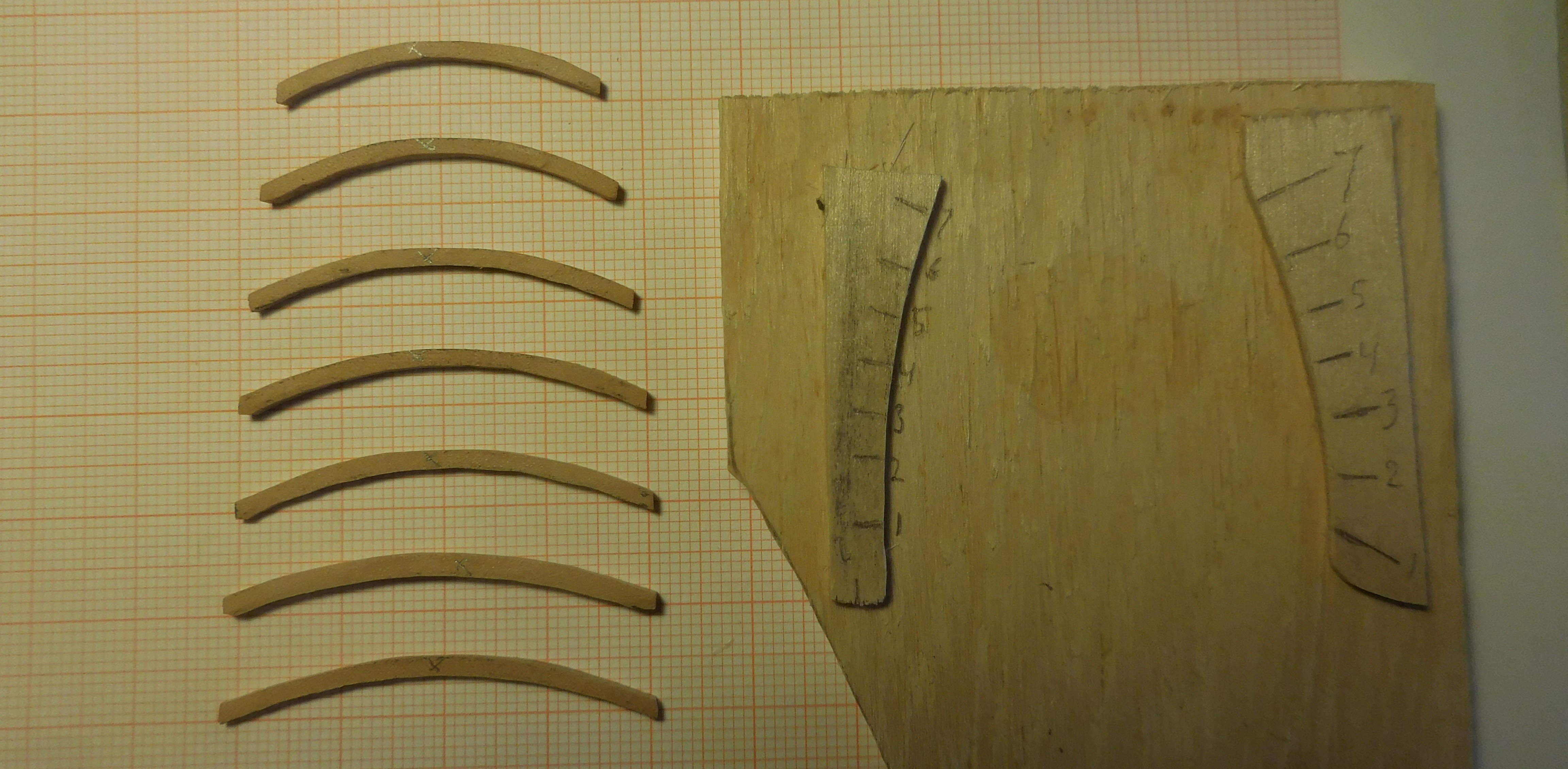
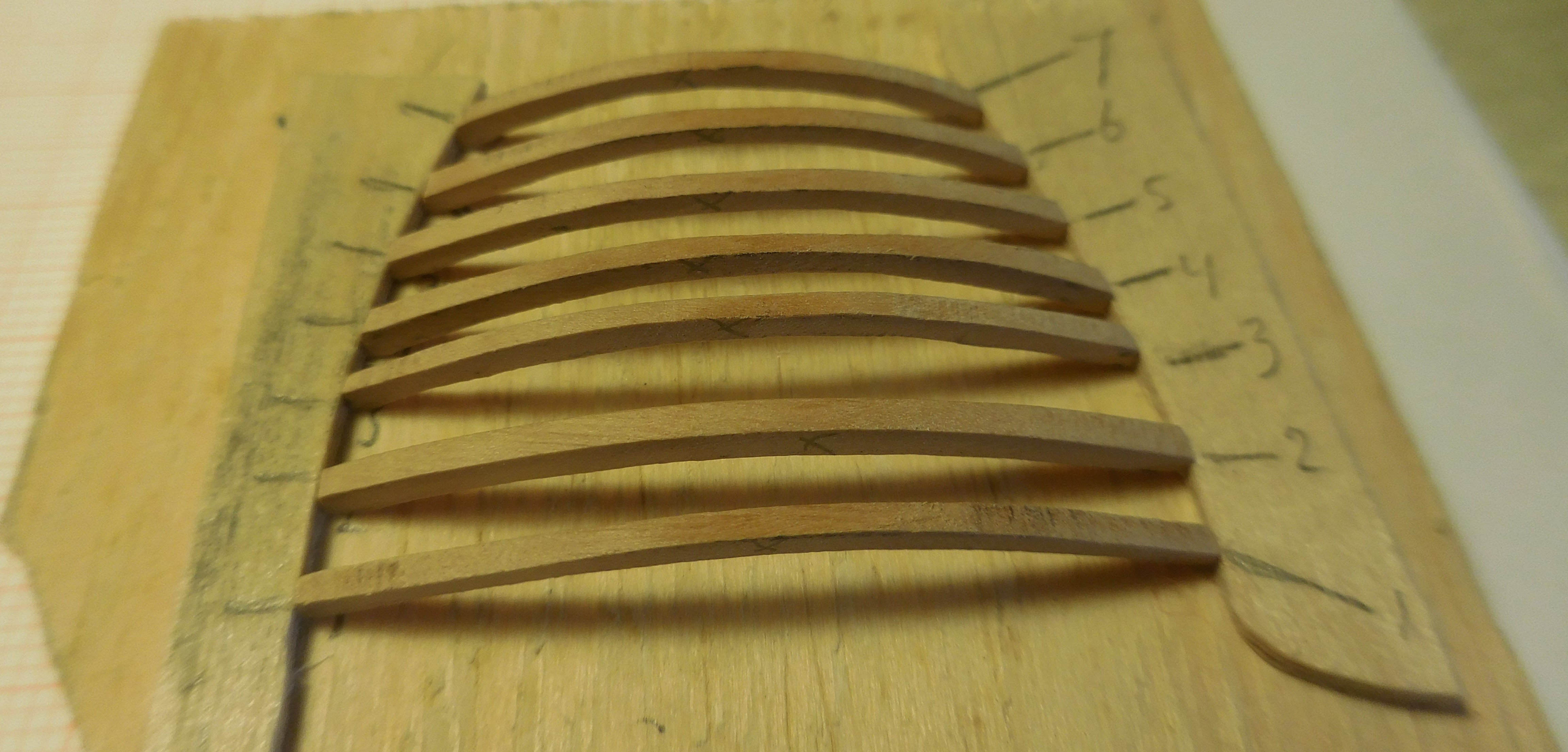
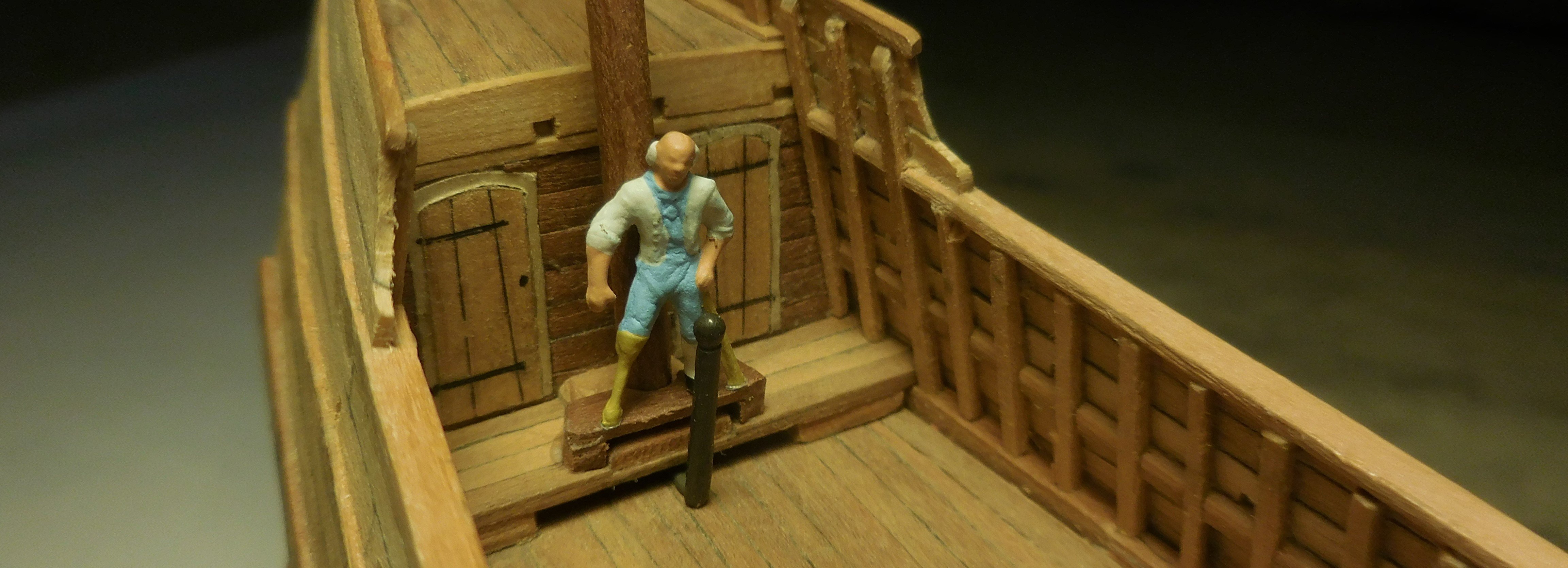
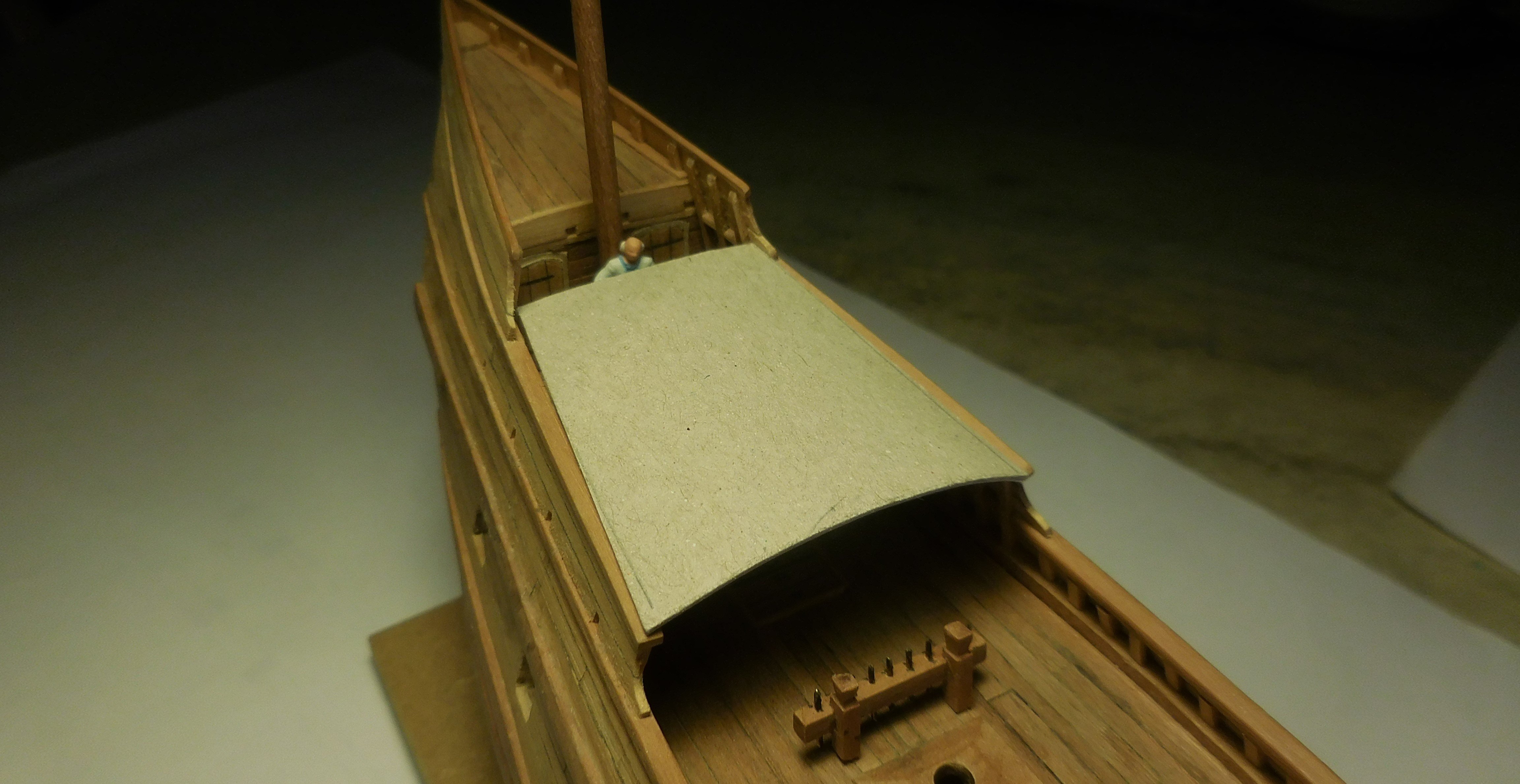
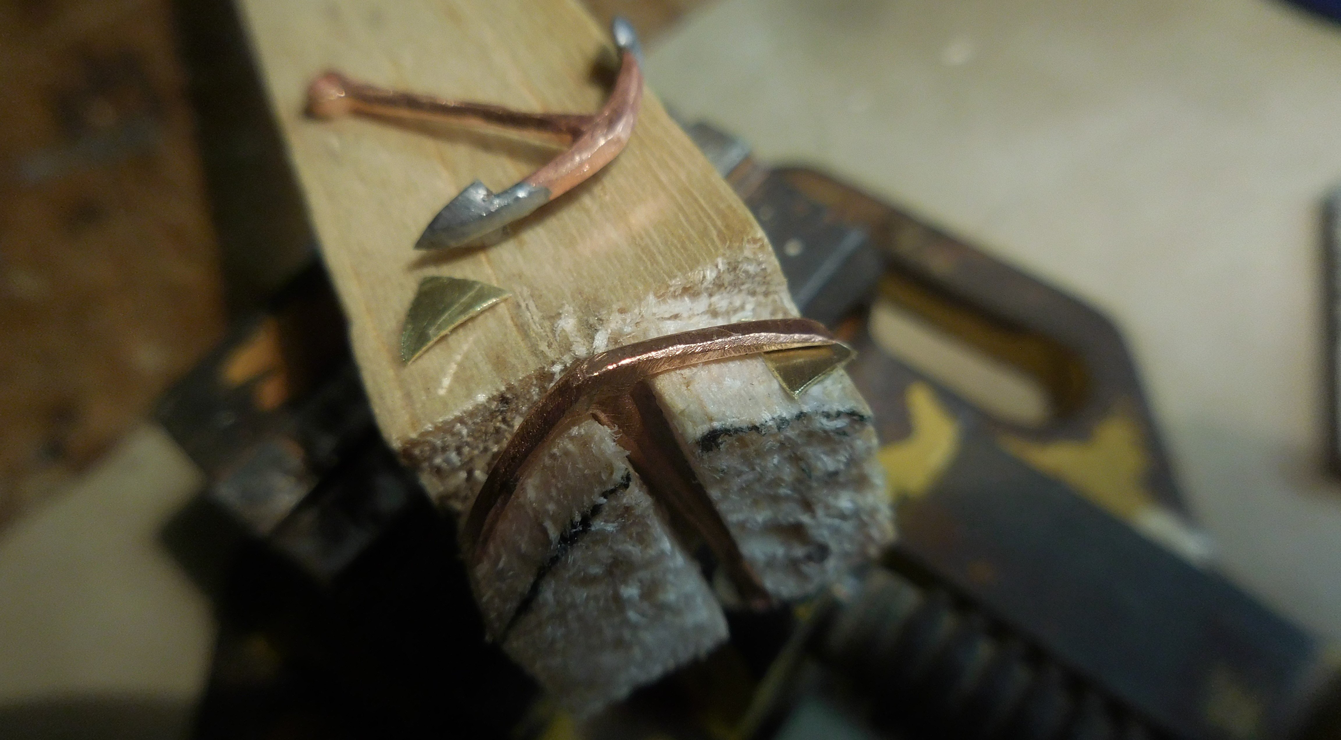
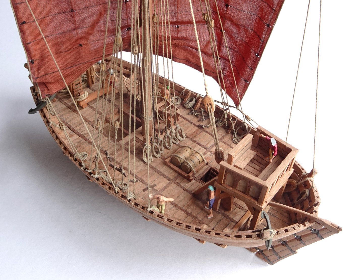
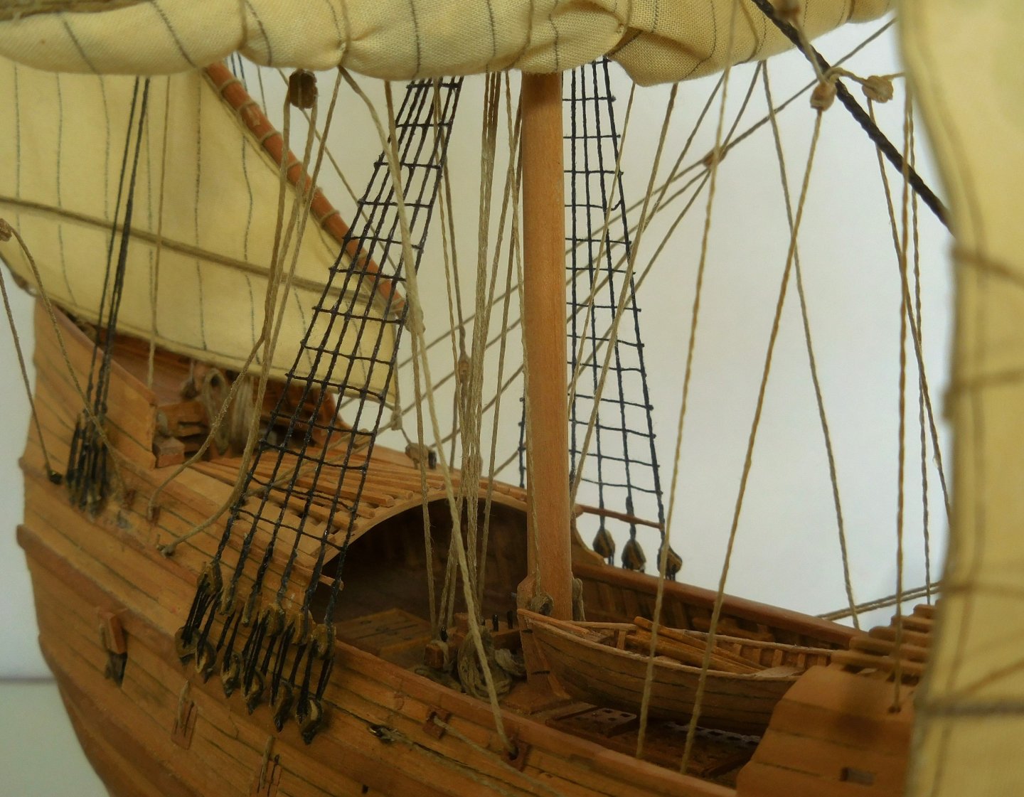
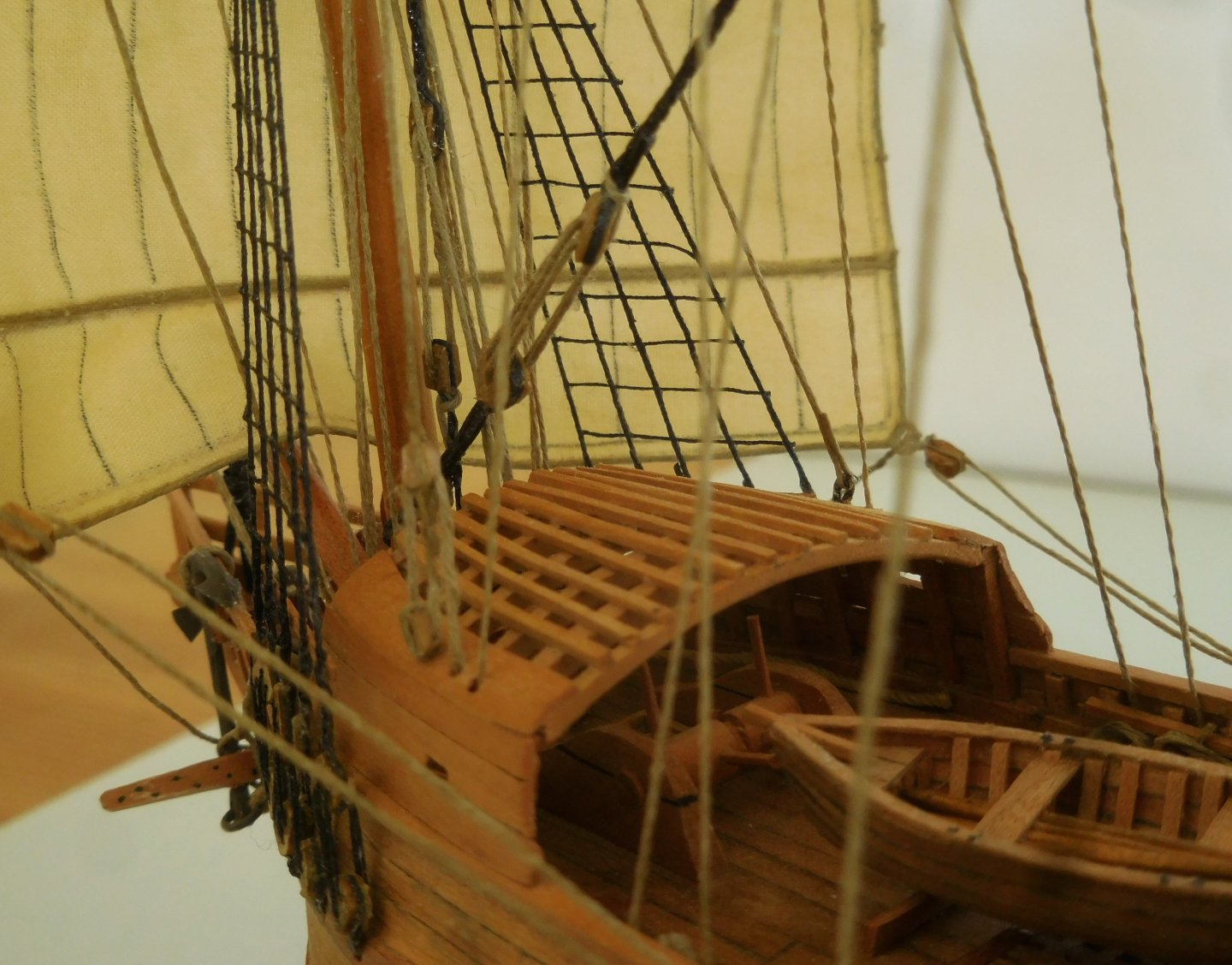
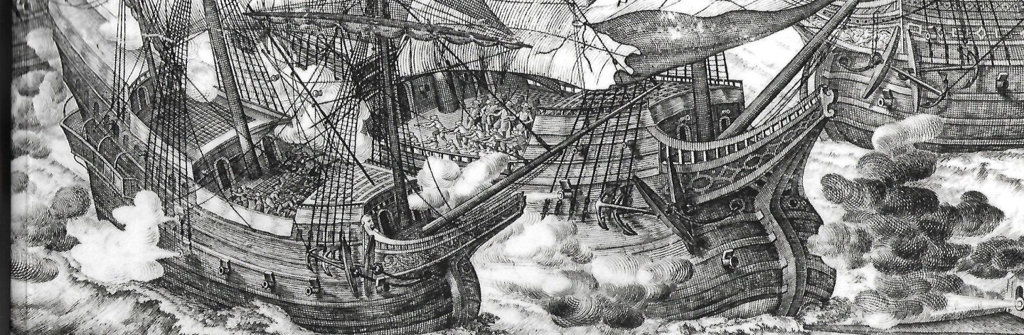
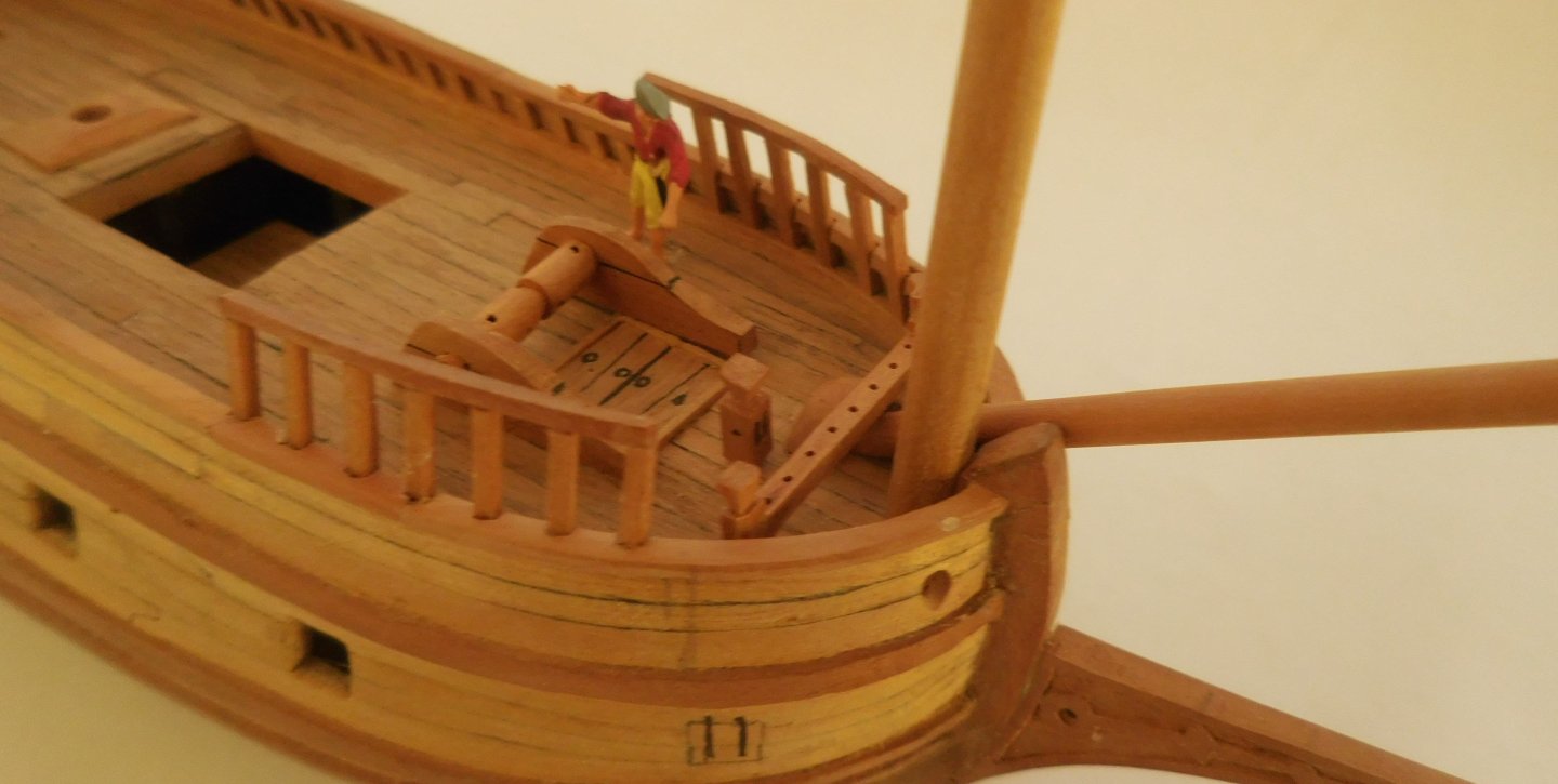
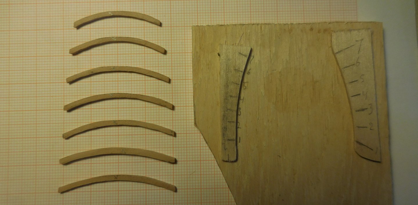
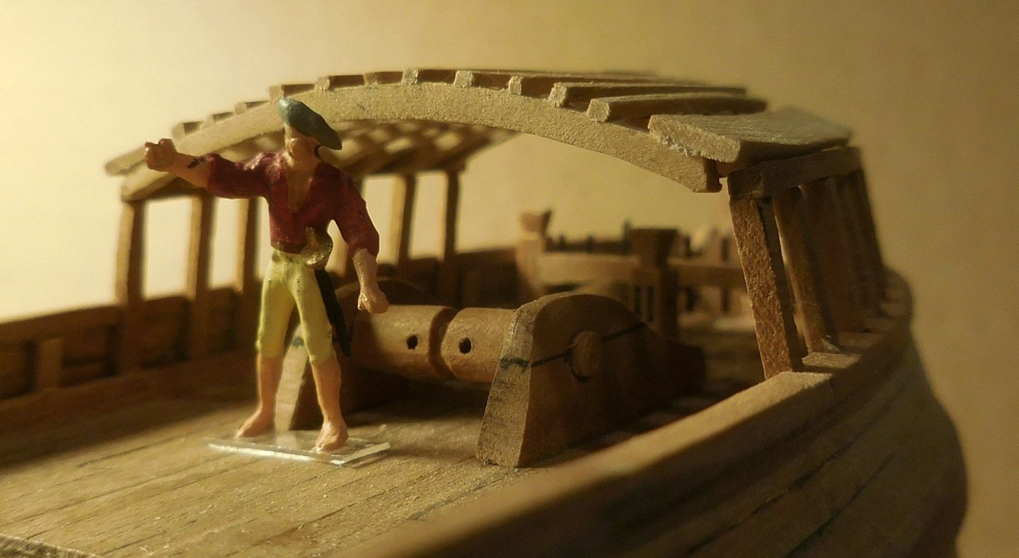
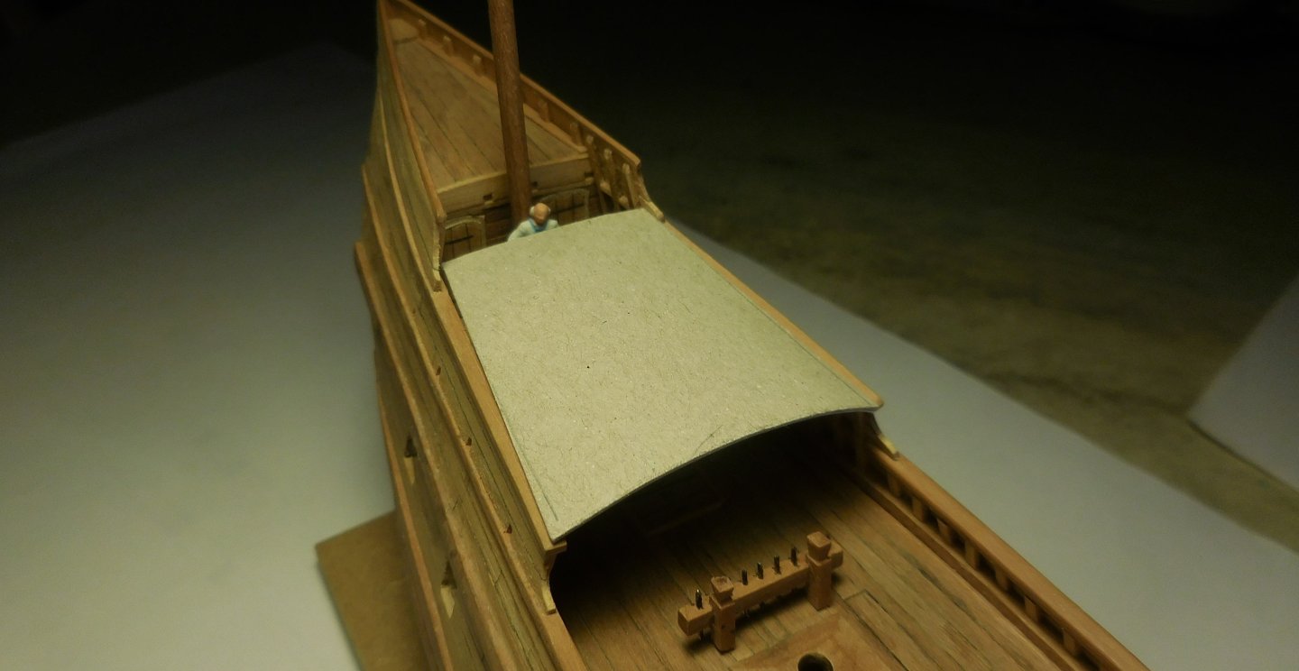
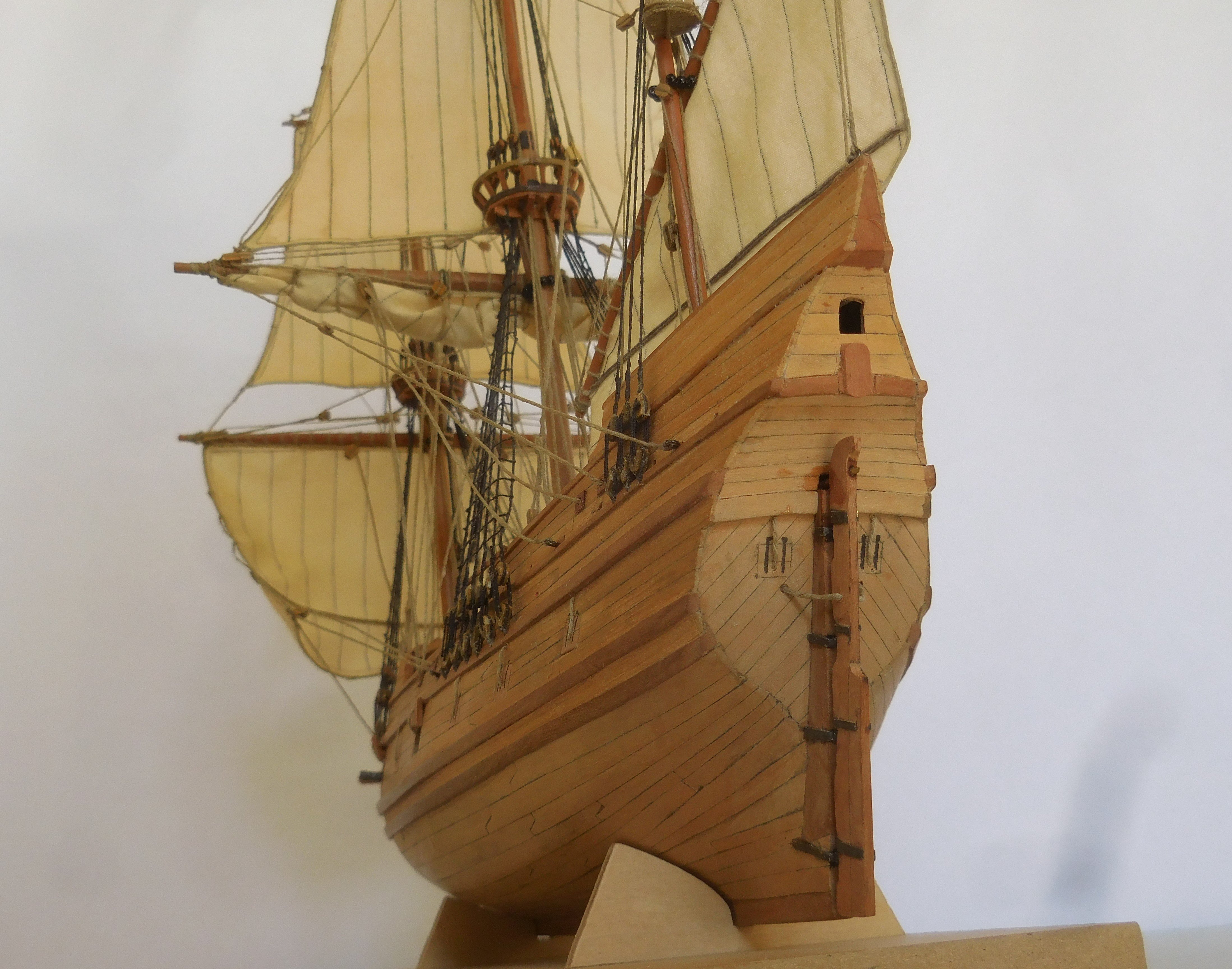
6 On the forcastle, and midships, I built a lattice as can be seen on this old picture of the battle at Bantam in 1601. This lattice was a feature which was common on merchant ships at the time. It had to be a defense system in case the ship would be boarded by pirates. Initially, it was a net of heavy ropes, but later it became a wooden lattice. I only know the Dutch name for this construction "boevennet". If you were to translate it, it would become "crook's net" The holes in the grid were such that they could be used to poke with spikes to target the attacker on the net from below. Much later, this completely disappeared and the lattice became a permanent deck. On each side I attached stanchions which had to support the lattice over the forcastle. The lattice must then be placed on top of this, consisting of a number of curved beams with slats attached transversely. The beams do not have the same width, but they must have the same height. Each beam had to be calculated and drawn separately, and sawn from thin pear wood. On the shelf next to it, the mold is made that corresponds to the tops of the stanchions. To determine how high the lattice should be, a HO figure of a sailor was placed underneath before attaching the construction. It looks like a tall construction, but the headroom underneath is barely 170 cm in the middle. In order to be able to determine the correct shape of the lattice midships, a helmsman was placed who had to be able to see just over the lattice It turned out that the construction became almost horizontal at the rear and curved at the front. This shape was adopted on the rafters that were placed on the edges midships. A ship of that size usually carried three anchors. I made two of them, of different sizes. They are sawn from a brass plate of 2 mm thick, on which I first glued the paper with the right circumference, and then filed it into the right shape. Both palms are made of very thin brass and cut into that shape. The parts are soldered together. This was simply not possible because of the conduction of the heat. A tool was made with a block of balsawood in which the contours of the bottom of the anchor were filed. By clamping the anchor on top of it and sliding the palms underneath, it became a solid unit that could easily be soldered. After that, sticks were made from two halves of pear wood. Then I painted them in a color: Revell 46 matt. The cannon barrels were also given that colour. Both anchors were placed on the bow. Catheads wer not used at that time. I didn't think it was realistic to equip all gun ports with cannons. Only two of them were fitted with sawn-off cannon barrels. Furthermore, I left two gates open, the others were closed. Channels on which the deadeyes for the shrouds were mounted were not in use in that time. They were attached on a wale. As can be seen on illustrations.


.JPG.4d4653ce497f41316f5f0a5d5bf4f454.JPG)
-kopie.JPG.9474df526e145b7a9fdbb8071810dbf0.JPG)
.JPG.5759e67d5d2453cf30c71a31c9d97465.JPG)

.JPG.6788aa9f6ebf3ae179c7135e5ddaa6bc.JPG)


.JPG.4d94e990131f99377e1d0b53e330e294.JPG)