


SteveLarsen
-
Posts
41 -
Joined
-
Last visited
Content Type
Profiles
Forums
Gallery
Events
Posts posted by SteveLarsen
-
-
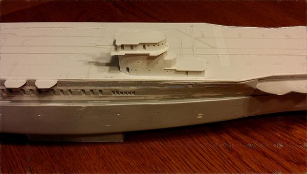
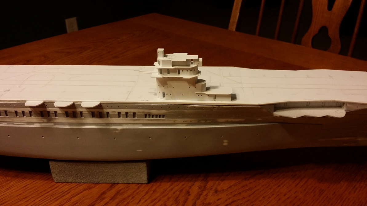
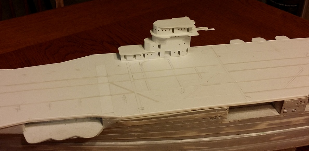
Flag Bridge (above the Navigating Bridge) and Air Defense Bridge (highest level) coming together.


- hexnut, gieb8688, GrandpaPhil and 3 others
-
 6
6
-
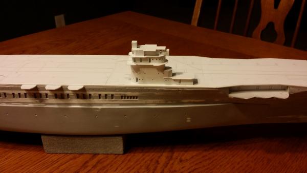
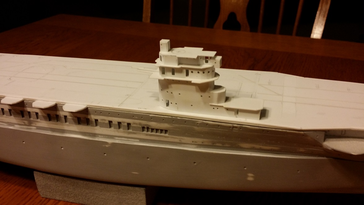
Conning tower work continues. The Navigating Bridge (with Pilot House up front) is now on top. Two more levels upwards to go.
Port side:
Starboard side:
- mtaylor, GrandpaPhil, gieb8688 and 3 others
-
6
-
-
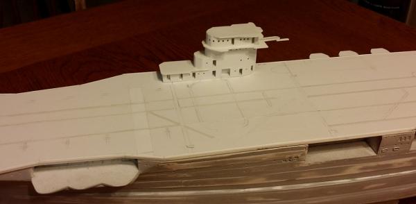
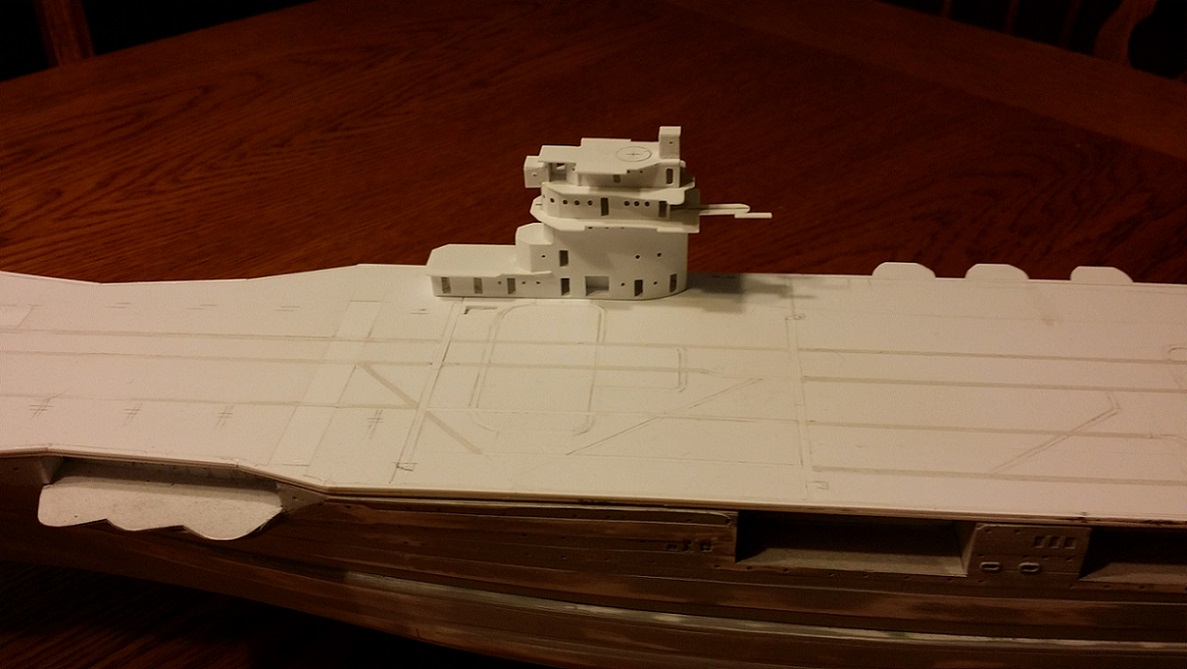
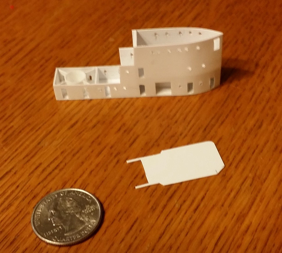
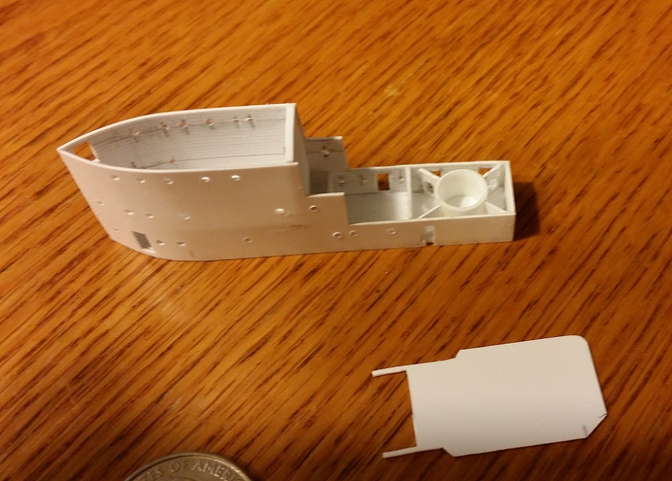
Here the lower three levels of the conning tower's hatches have been opened up.
Since open hatches make any major interior features visible, it was necessary to build and install the barbette for a twin 5-inch mount and its associated radial bulkheads. Each of the four bulkheads has a passage cut into it. The real ship had six bulkheads but two will not be visible when the conning tower is complete so I omitted them.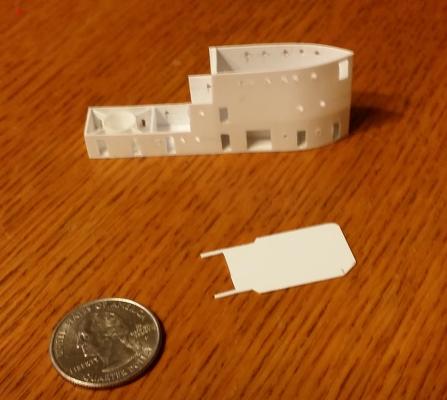

-
Starting to work on the Conning Tower. The base and internal stiffener are .40 thou. styrene sheet for strength. The sides are .20 thou V-groove with the horizontal grooves on the interior of the tower. I have found that using the grooves as guides helps assure aligned portholes, platforms, hatches, etc.
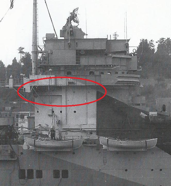
If you look closely at the top row of portholes on the starboard side, you will notice that I cut the aft-most two portholes a bit elevated compared to those forward of them. This is deliberate and consistent with the actual ship. On the exterior of the real conning tower side, there is a prominent exterior cable conduit just under these two portholes. Behind these portholes on the real ship was a radar control compartment. Presumably, the conduit contained cables associated with the ship's radars or other electronic gear.
-
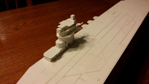
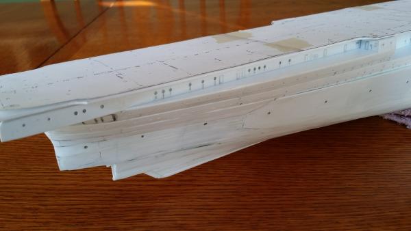
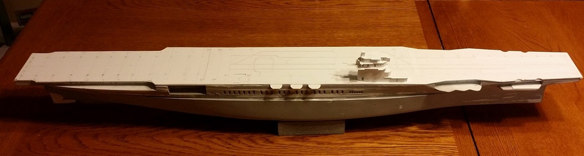
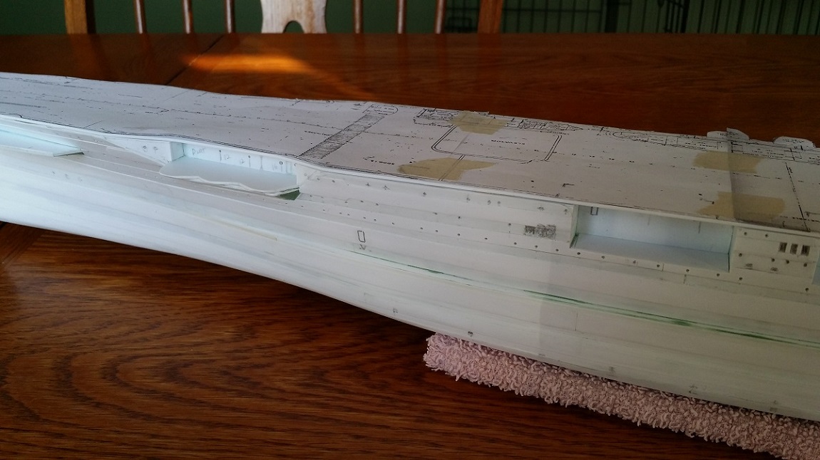
Flight Deck. This is the flight deck with major structures in place but still very rough.
Much cleanup to be done but you can see
1. complex planking patterns.
2. the location of the floatplane tracks consistent with available photos.
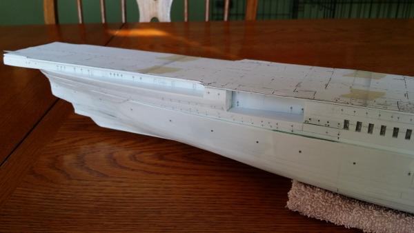
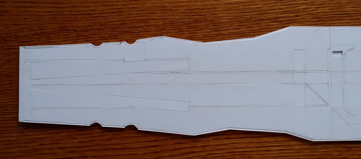
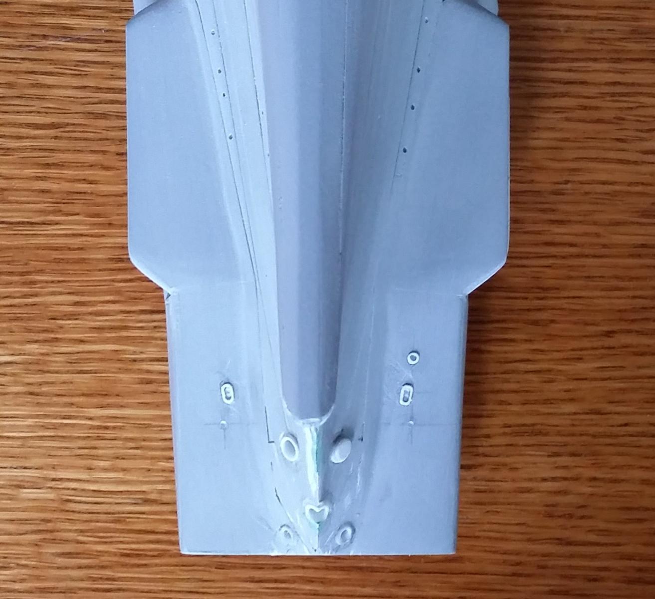
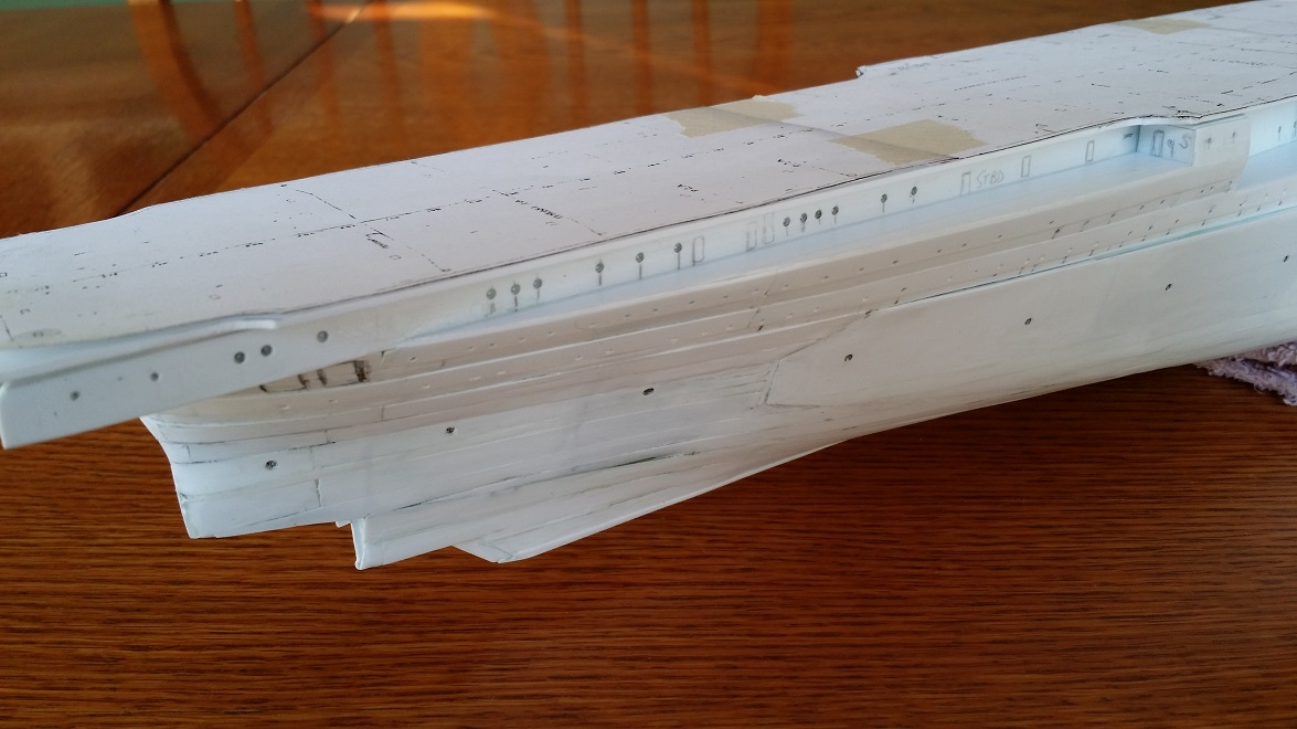
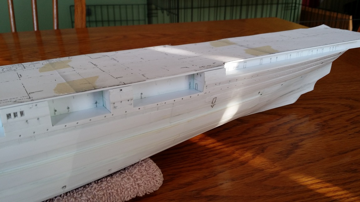
3. the deck-edge waterways are installed.Bow. Deck-edge waterways are present. The deck-edge cutouts are clearance for quad Bofors mounts positioned one deck below on sponsons. The major structures are all in place. It needs some cleanup and seam-filling. The elevation of the floatplane tracks needs to be evened out and matched to the planked flight deck. That will be done with putty.
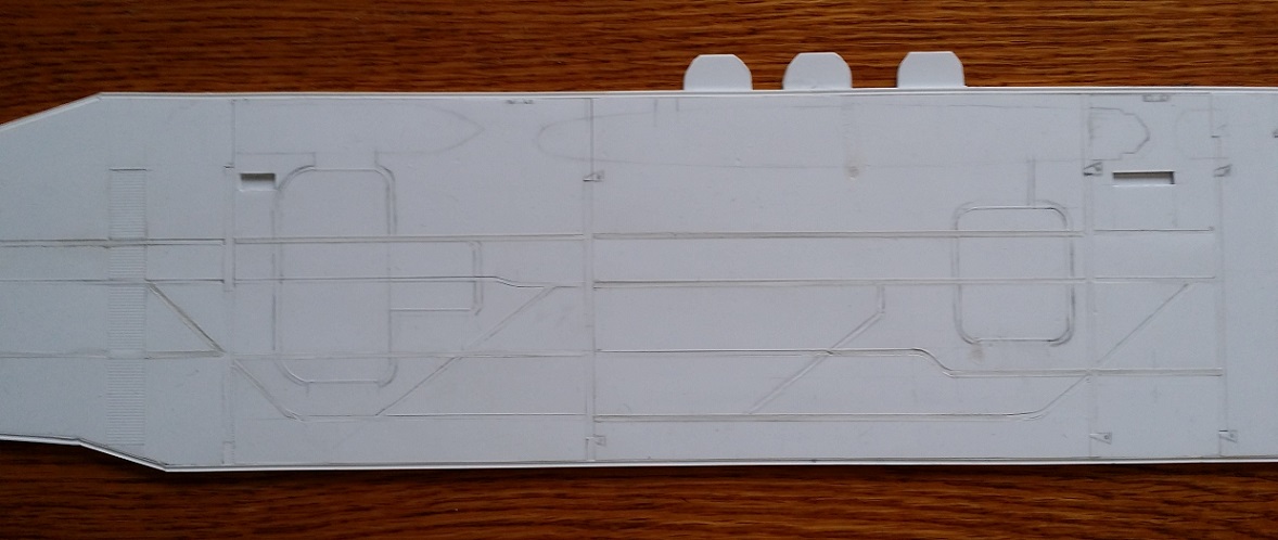
Midships. Bow to left. Open bomb and torpedo elevators. There is still some cleanup and filling here to do. And the floatplane tracks need some evening out to match their height with the planked flight deck surface. That will be done with putty.
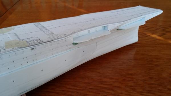
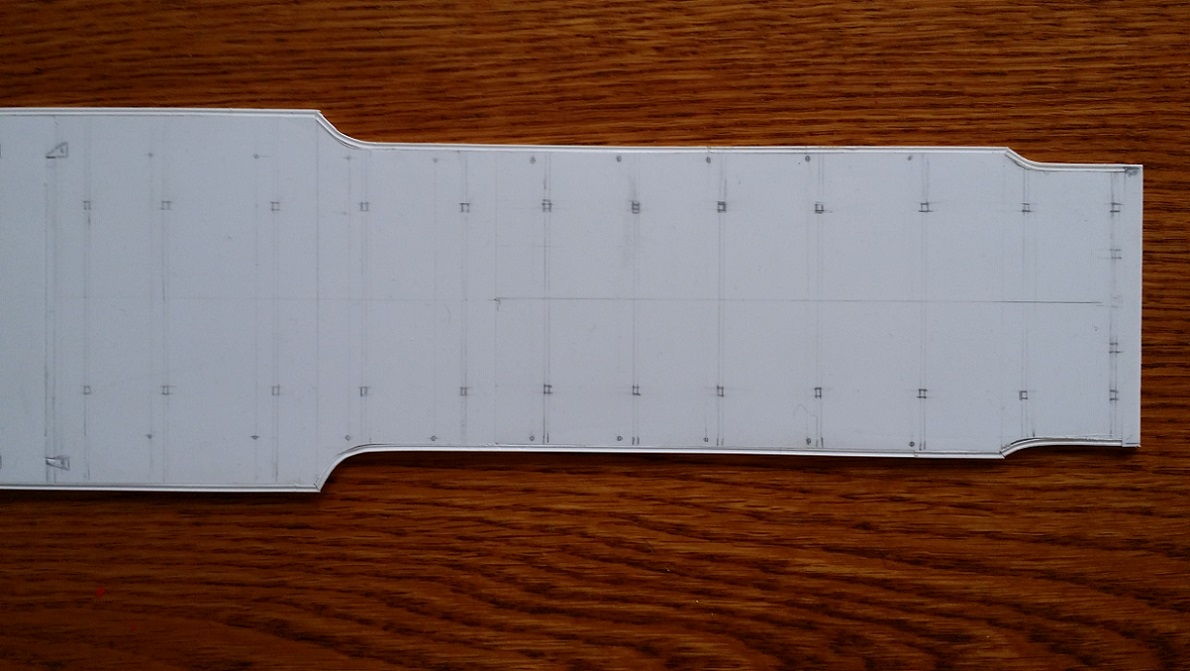
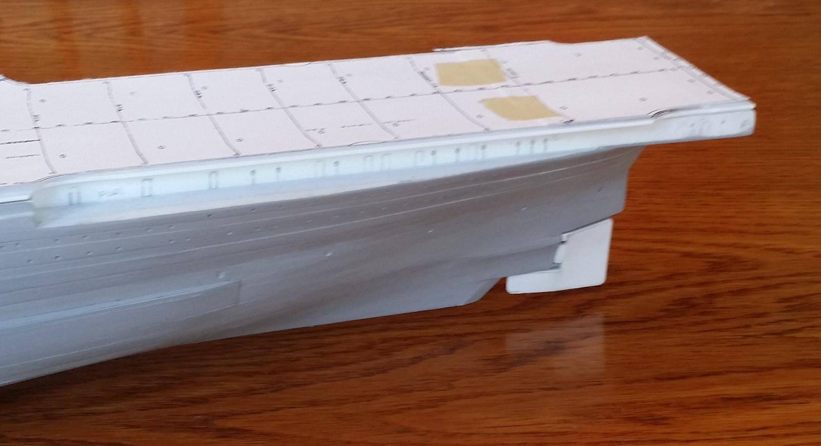
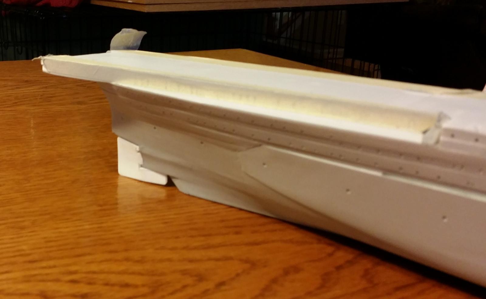
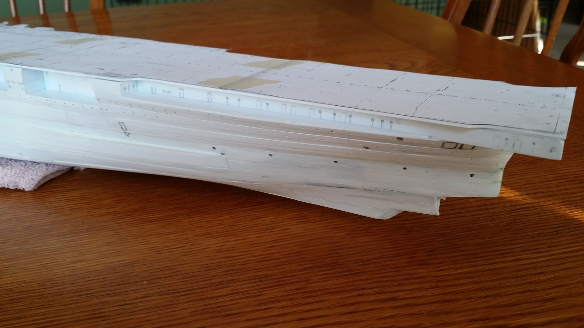
Aft. Compared to an Essex, the flight deck, particularly here, is quite narrow. There is some waterway adjustment and filling to do here but it's starting to look like it should.
Arrestor cable anchor point details to be added next. Note for carrier model builders: a common error modelers make is the laying of the arrestor cables on the wrong side of the anchor points. The arrestor cables on US Navy carriers lay on the aft side of the anchor points.
Also next, three quad Bofors mount platform bases and splinter shielding to be built next to the funner base. Round downs need more work but they're getting there.
Conning tower and funnel coming soon.- GrandpaPhil, ScottRC, mtaylor and 4 others
-
7
-
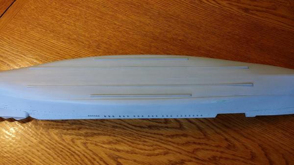
Here's an excerpt from the 1936 design showing the asymmetrical hull to good effect as well as the proper, and structurally logical, location of the docking keels. The hull bottom is not flat but has a subtle deadrise.
Notice the starboard stability blister. Here at midships, the outboard blister side is vertical and extends a considerable distance from the side of the hull. Also note that the starboard side has no bilge keel. The port side bilge keel is present.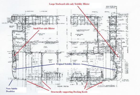
-
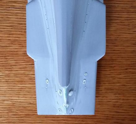
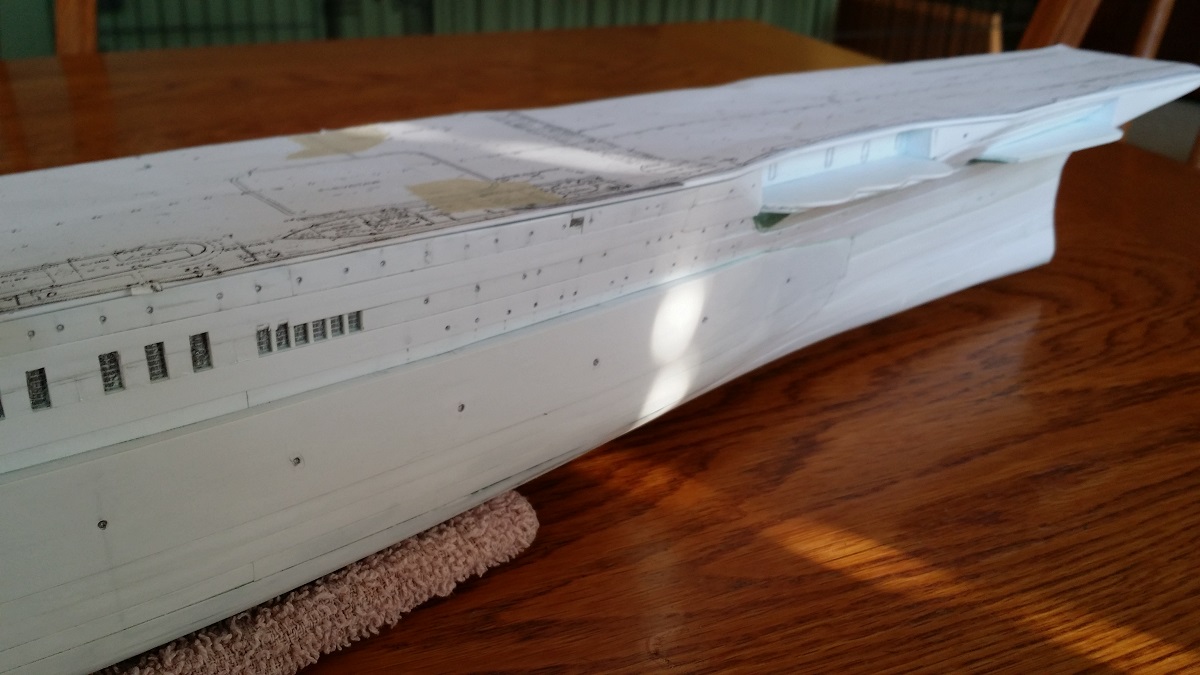
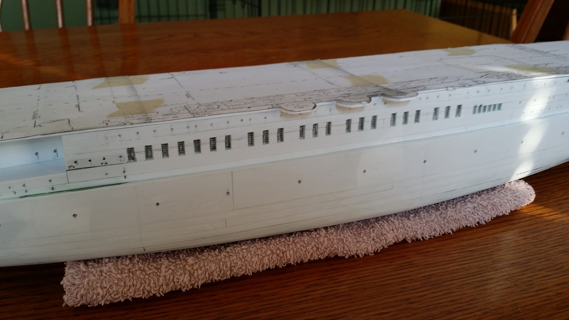
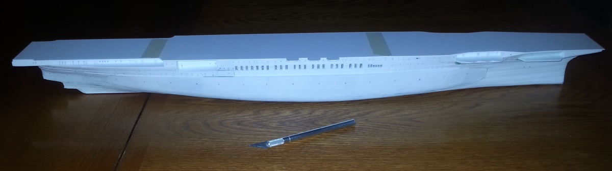
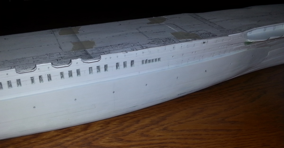
Here you can see that chocks and hawse pipes have been roughed in, docking keels have been installed, and the hull has been primed. In 1942, Saratoga's starboard main anchor hawse pipe had been conspicuously plated over. Next installations include propeller shaft housings and port-side bilge keel (no starboard-side bilge keel after the installation of the large starboard side stability blister).
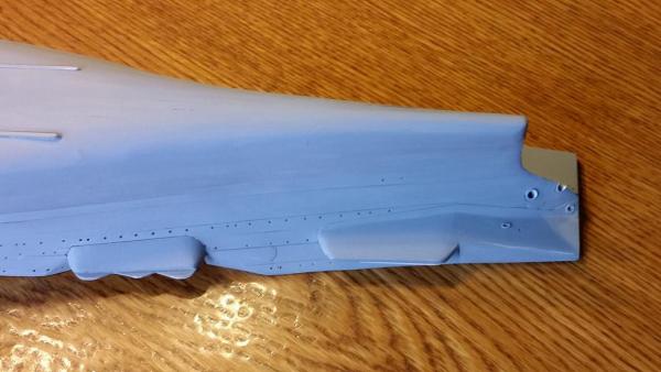
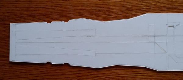
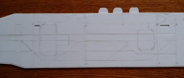
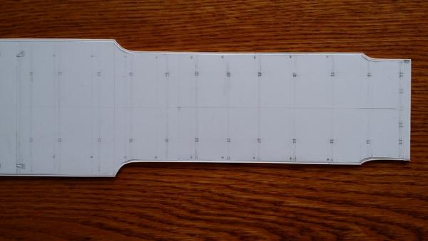
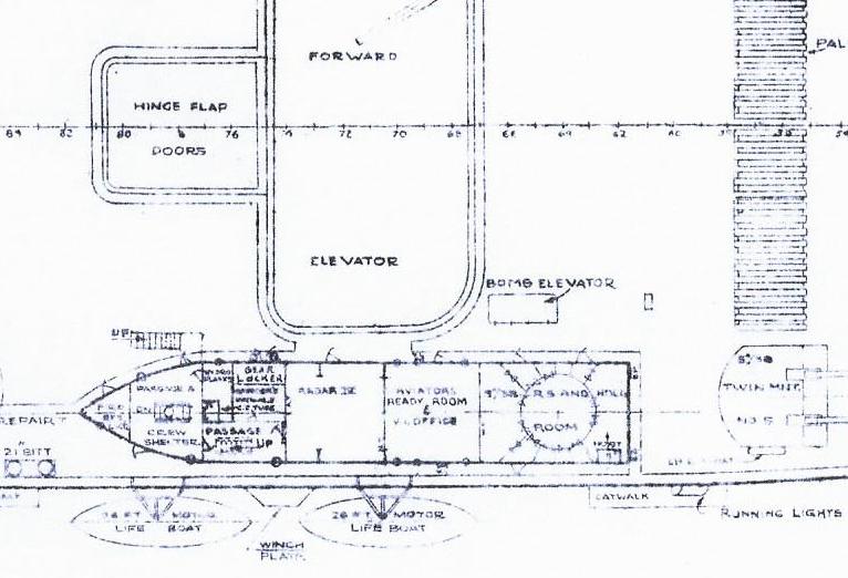
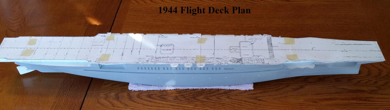
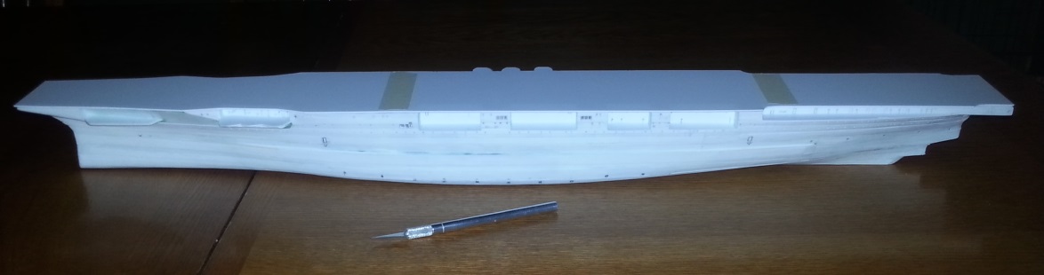
Taking a break from further detailing the hull, Flight Deck work has begun. The flight deck's major structures and details for 1944 have been penciled on the styrene deck. Plans for the 1944 flight deck and 1945 flight deck lay alongside for comparison purposes.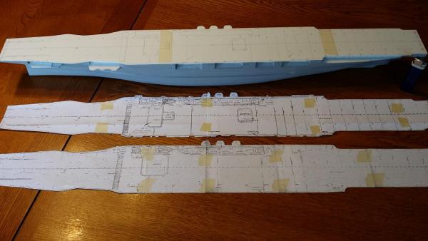
- GrandpaPhil, mtaylor, qwerty2008 and 3 others
-
6
-
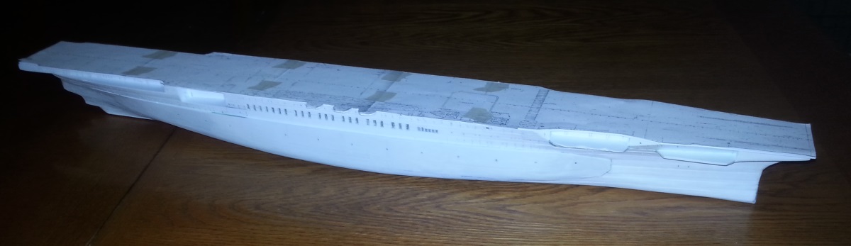
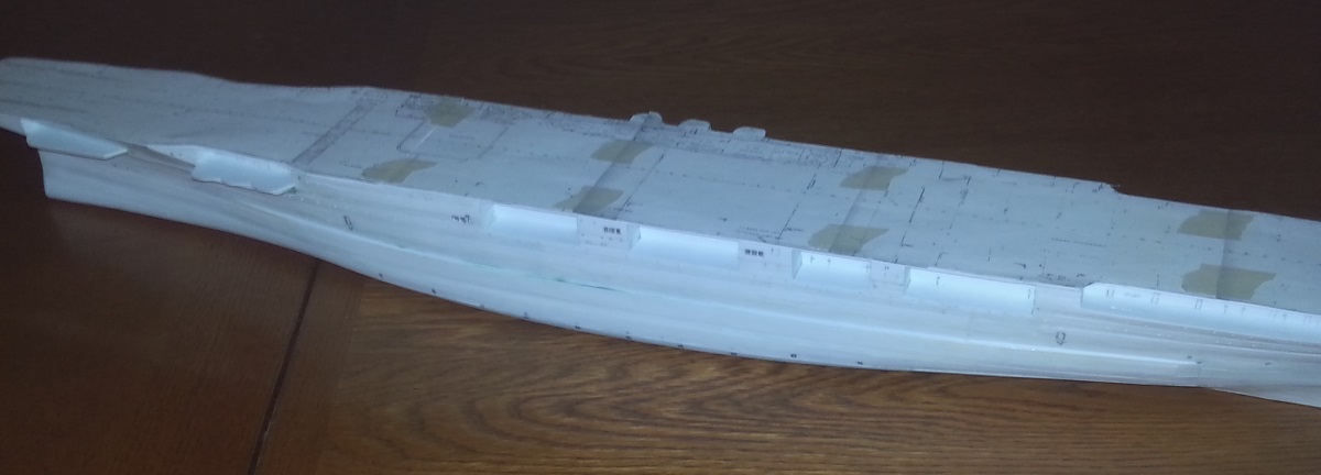
Compare the 1944 flight deck plan laid on top the model with the 1945 post-Kamikaze refit flight deck plan.
During repairs following the Kamikaze strikes, the forward elevator was replaced with a much-anticipated larger elevator. The aft elevator was deleted.
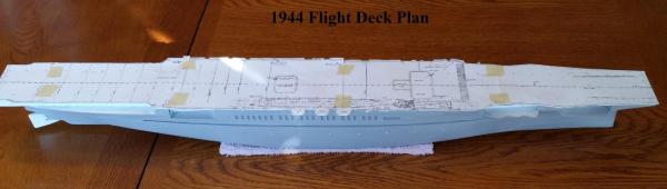
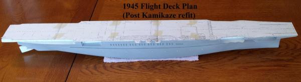
The model is being built according to the ship's late 1944 appearance with two aircraft elevators.
- hexnut, GrandpaPhil, mtaylor and 4 others
-
7
-
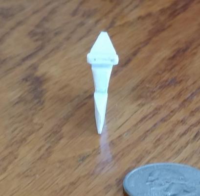
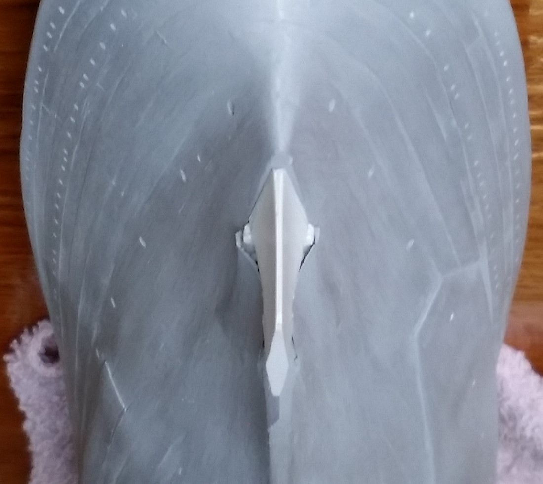
Here is the rudder placed on the hull. It is not yet cemented into position.


-
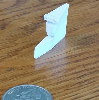
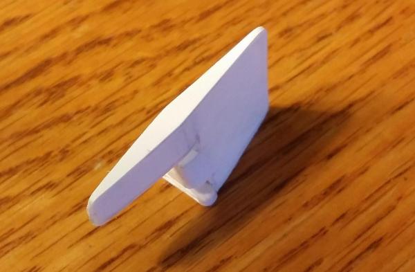
One of the most interesting features of the two sisters of the Lexington class is the rudder. It has a distinct flare at the top that conforms to the shape of the hull and the bottom is in the shape of a diamond. Also interesting, the rams which operate the rudder are partially exposed. I have tried to capture the complex shape of the original rudder.

Compare the effort above with the 1/350 scale Trumpeter kit rudder below which appears to be accurate in profile but wholly inaccurate in shape.
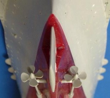
The aft end of the starboard stability blister is just visible in the first photo. At this end, the outboard blister side tightly conforms with the contour of the hull. At midships, the outboard side is vertical and extends a considerable distance from the side of the hull.
Strake detail is also visible in the top photo. It was a swine to get to look good and considerable study of photos of the actual ship was necessary to identify, locate, measure and position each strake. This was only possible thanks to Tracy, Dave Doyle, and the hull sections on sheets 18 and 19 of the 1936 plans.More photos of the scratch-built rudder:
- gieb8688, mtaylor, GrandpaPhil and 5 others
-
8
-
Starboard side:


Port side:


-
The hull under construction.


- hexnut, Old Collingwood, GuntherMT and 4 others
-
7
-
-
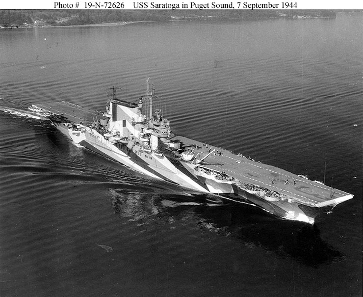
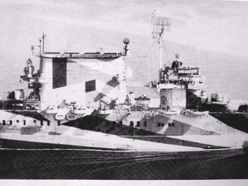
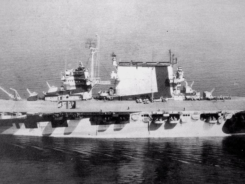
Scratchbuilding USS Saratoga CV-3, 1944 in 1/350 scale.
This model will depict Saratoga late war with asymmetrical hull, cut-down funnel, and heavy AA fit. It is NOT being converted from the Trumpeter kit.
Jim Russell did convert the Trumpeter kit into a 1944 Saratoga beautifully. You can see his conversion here: http://www.shipmodels.info/mws_forum/viewtopic.php?f=59&t=39515&start=0
Actual ship length overall: 910' - 1-3/4"
Model Length: 31.205 inches (79.26 cm).
Material: Evergreen polystyrene sheet, strips, tubing, rods, H-sections, etc.
Hull construction method: double plank on frame
Plans and References:
1. US Navy Booklet of General Plans dated 1942 (implemented following Kamikaze damage sustained on February 21, 1945), available from Floating Drydock
2. US Navy Booklet of General Plans dated April 23, 1936 (implemented during a refit in December, 1943, plans updated Aug., 1944 to include cross sections - vitally important for this build).
3. US Navy Booklet of General Plans for USS Lexington CV-2, dated 1936, for comparison
4. detail photos and comments posted by Tracy White (invaluable)
5. photos from USS Saratoga Squadron at Sea by David Doyle (Tracy contributed much to that effort).
6. hull sections for USS Lexington CV-2, drawn by Thomas Walkowiak, available from Floating Drydock.
Technique inspiration:
Paul Budzik's masterful scratch-built USS Enterprise CV-6 http://paulbudzik.com/current-projects/Enterprise%20Scratch/Enterprise_Scratch.html
Finish inspiration:
Martin Quinn’s exquisite prewar USS Lexington CV-2:
http://www.modelshipgallery.com/gallery/cv/cv-02/350-mq/mq-index.html
Your advice, constructive criticism and comments are most welcome and appreciated.
- hexnut and Rik Thistle
-
2


USS Saratoga by Steve Larsen - PLASTIC - 1:350 as she appeared in 1944
in - Build logs for subjects built 1901 - Present Day
Posted
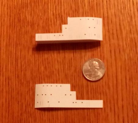
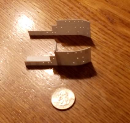
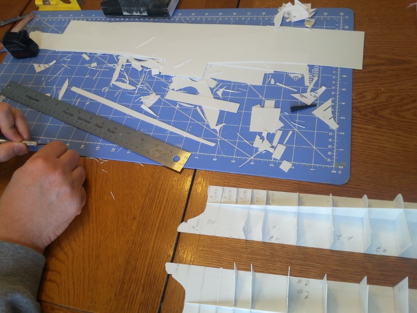
Here are some photos of the uptake casing placed on the flight deck. Around the casing will be built the funnel. The casing replicates the real ship's four enormous boiler uptakes (the words "uptakes" and "smoke pipes" are both used in the Navy plans). It is essentially a compartmentalized box made from 0.040" Evergreen V-groove sheet styrene. The thickness provides the funnel with internal strength and stiffness while the V-groove helps with alignment.
The four, large rectangular openings at the top are the uptake exhausts and will be open with visible interiors when the funnel is complete. Therefore, the smooth side of the V-groove is used to form each of the four uptakes' interior. The grooves will all be hidden once the funnel is built up. The pencil marks on the casing exterior show the path of the uptakes.
The model is starting to be recognizable as Saratoga.