
Robert29
-
Posts
375 -
Joined
-
Last visited
Content Type
Profiles
Forums
Gallery
Events
Everything posted by Robert29
-
 Hi Graham, as always you come up with brilliant ideas how to tackle certain jobs. Those decorative scrolls are beautiful. I had also made some changes to the scrolls on my model, but your idea is impressive. Keep up you good work. Robert
 -
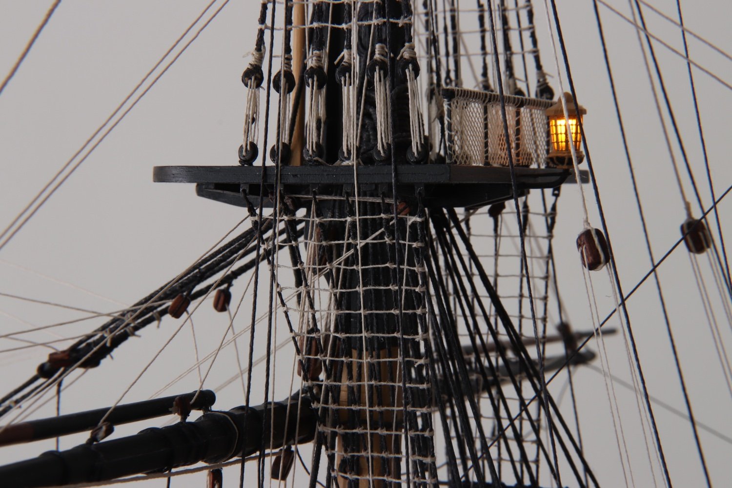
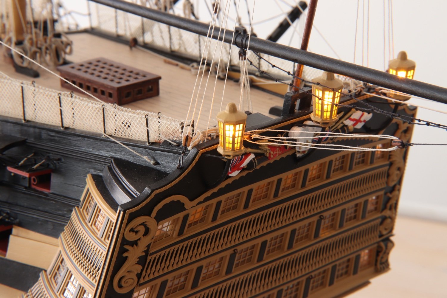
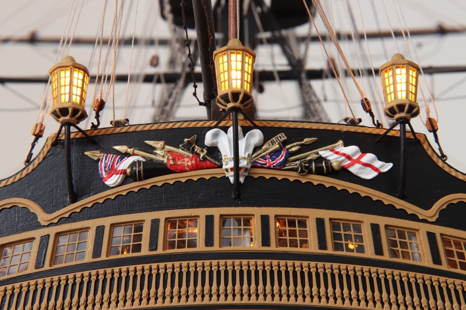
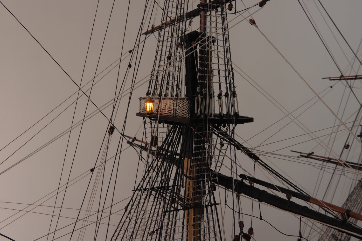
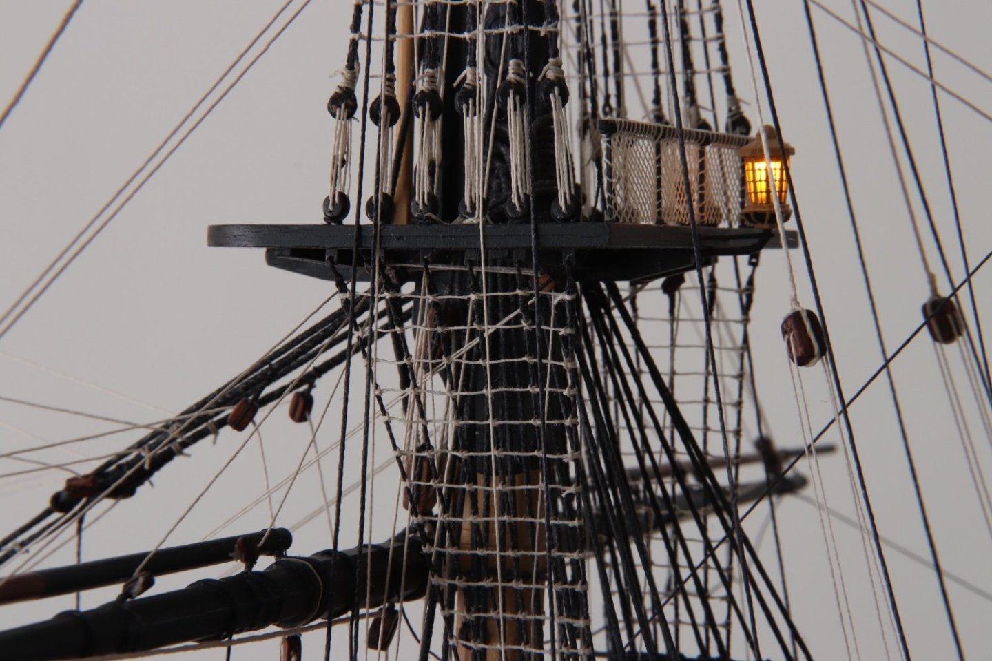
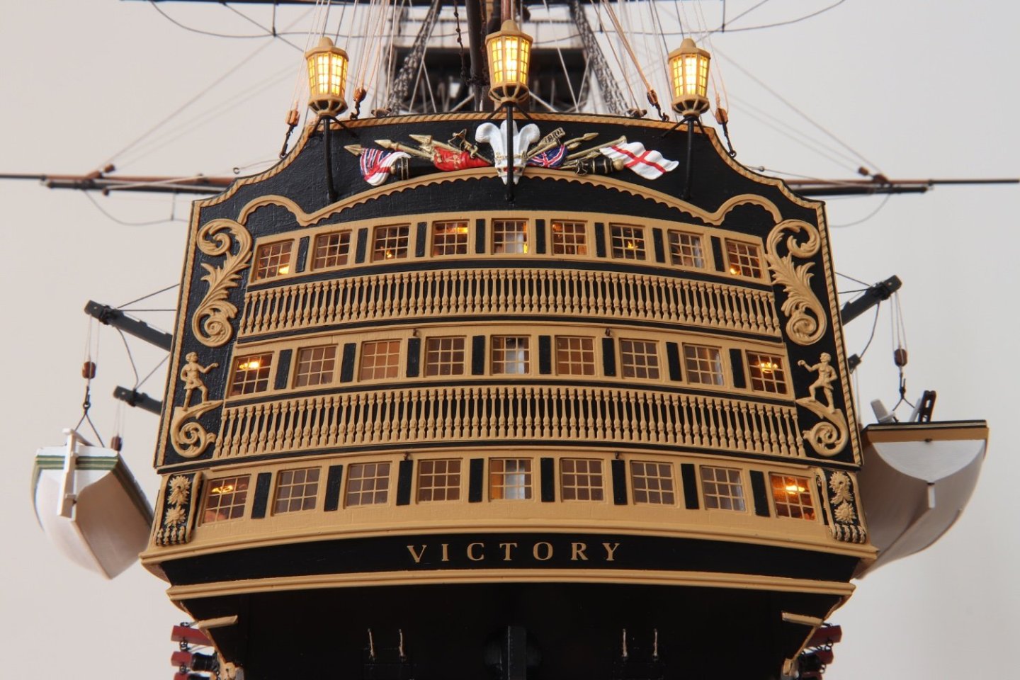
Thank you all for the comments. Bruce, As for the lighting, electronic wise I tried to keep it as simple as possible. Anything that goes wrong you cannot repair inside the model. The system only involves led's, a resistor for each led and wired them in parallel so I can put as much led's as I want to, just calculate the total amperage of the led's, and make sure the power supply (transformer, its practically impossible to run all those led's on batteries) has the adequate amperage. The other advantage of having them in parallel is that if any led or resistor is burnt, which is very unlikely, will not effect the others. Where possible I also wired them in a ring circuit so that if I have a wire becoming disconnected they will still have the voltage supply on them. My main concern was that I did not want to let any wiring showing, not even the once going out to the power supply. A thing I wish I would have done is have added just a few hanging lanterns on the quarterdeck and the bow so when lit in the dark more details could be seen. This would have been more difficult to hide the wiring. All in all I am quite satisfied with the result, but obviously there are always some things you would do differently if you had to do them agin. Robert
- 521 replies
-
- 4
-

-
- caldercraft
- victory
- (and 1 more)
-
Very nicely done Graham. Robert
-
Andrew, Chris, Graham, Sjors, Ian, Julian, Mort, Malcolm, B.E., Anthony, Mugje, thank you all for your coments. Also thank you for all the likes. Robert
- 521 replies
-
- 1
-
-
- caldercraft
- victory
- (and 1 more)
-
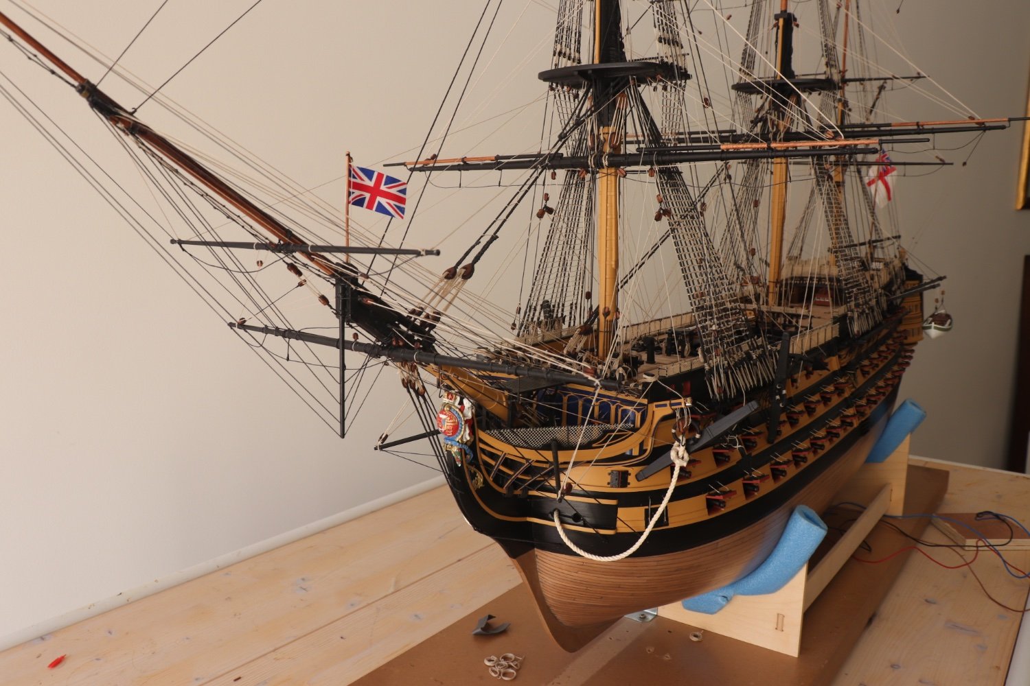
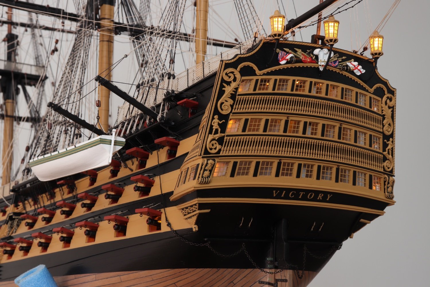
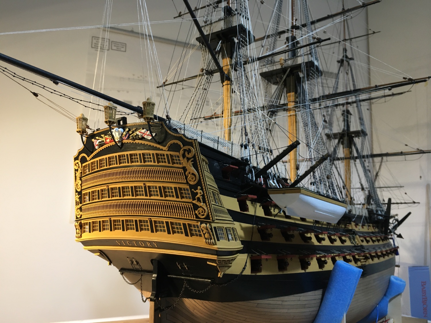
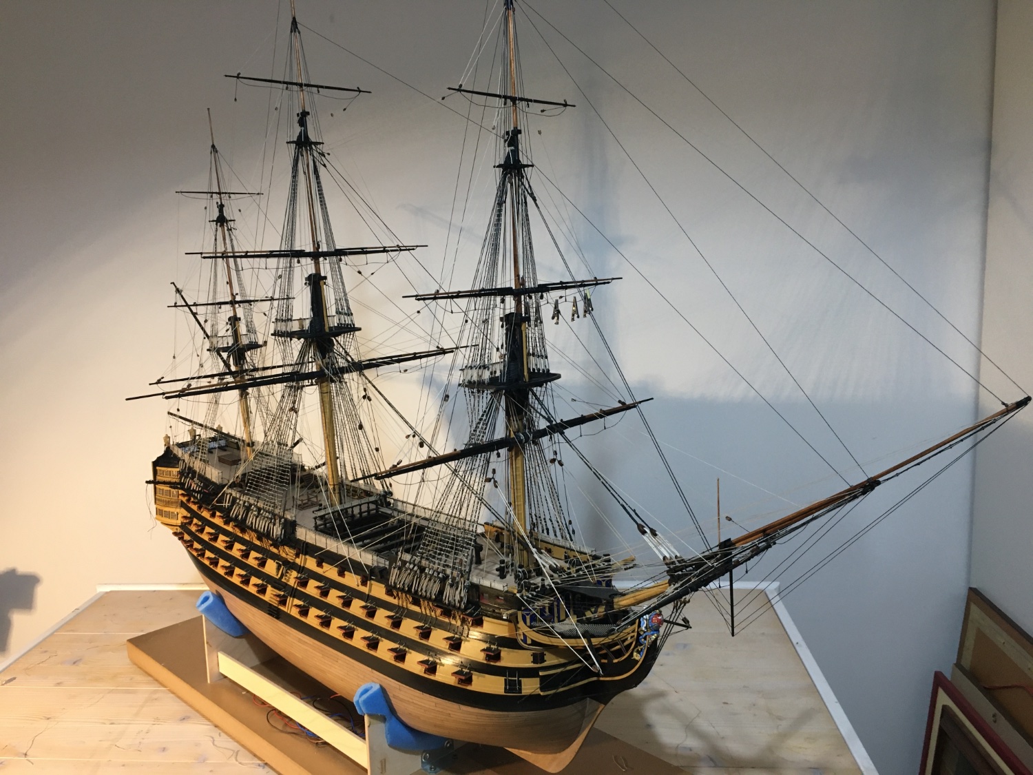
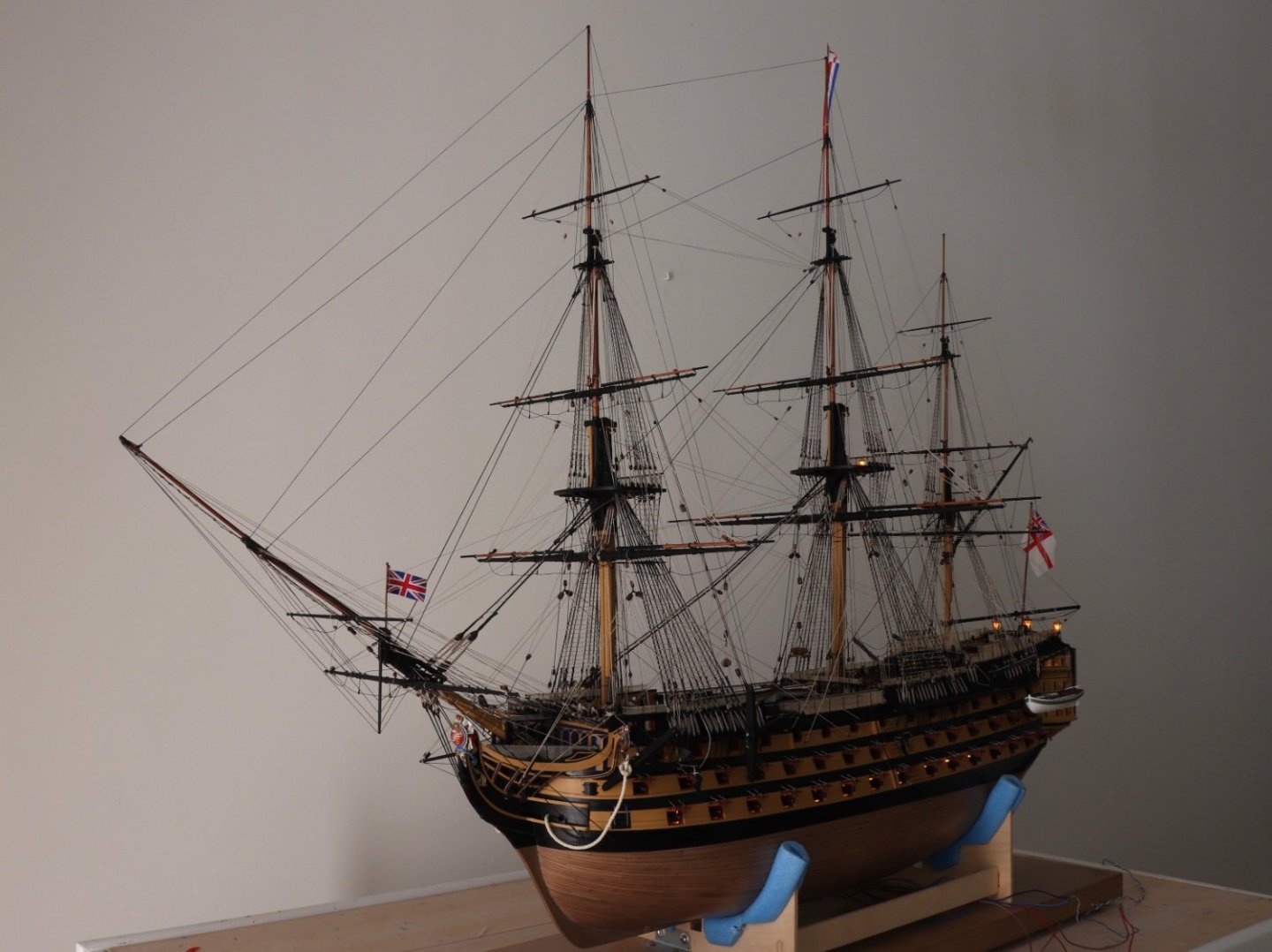
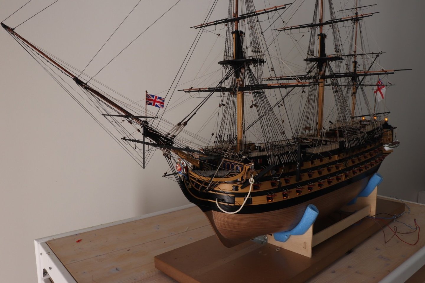
Finally HMS Victory long voyage comes to an end. I have posted a few photos but first of all I would like to thank all those who in any way contributed to my build, those who posted directly into my log, those who's logs I visited and took countless ideas, my log's followers and those who contributed with their encouraging comments and likes. I hope that my build would be of help to other builders, like so many others have been to me. Now I have to order an acrylic case to cover it and a table. I will post an image of it when I have it ready. Images with the lights on. Robert


- 521 replies
-
- 22
-

-
-
- caldercraft
- victory
- (and 1 more)
-
Some more detail to the Main Stay tackle Pendants. Robert The main stay fore tackle need some more tensioning. Robert

- 521 replies
-
- 10
-
-
-
- caldercraft
- victory
- (and 1 more)
-
Looking good Ron. Yes 0.5mm is quite thin and especially where the planks get narrower they break quite easily. Wetting and heating helps to minimise the problem. Robert
-
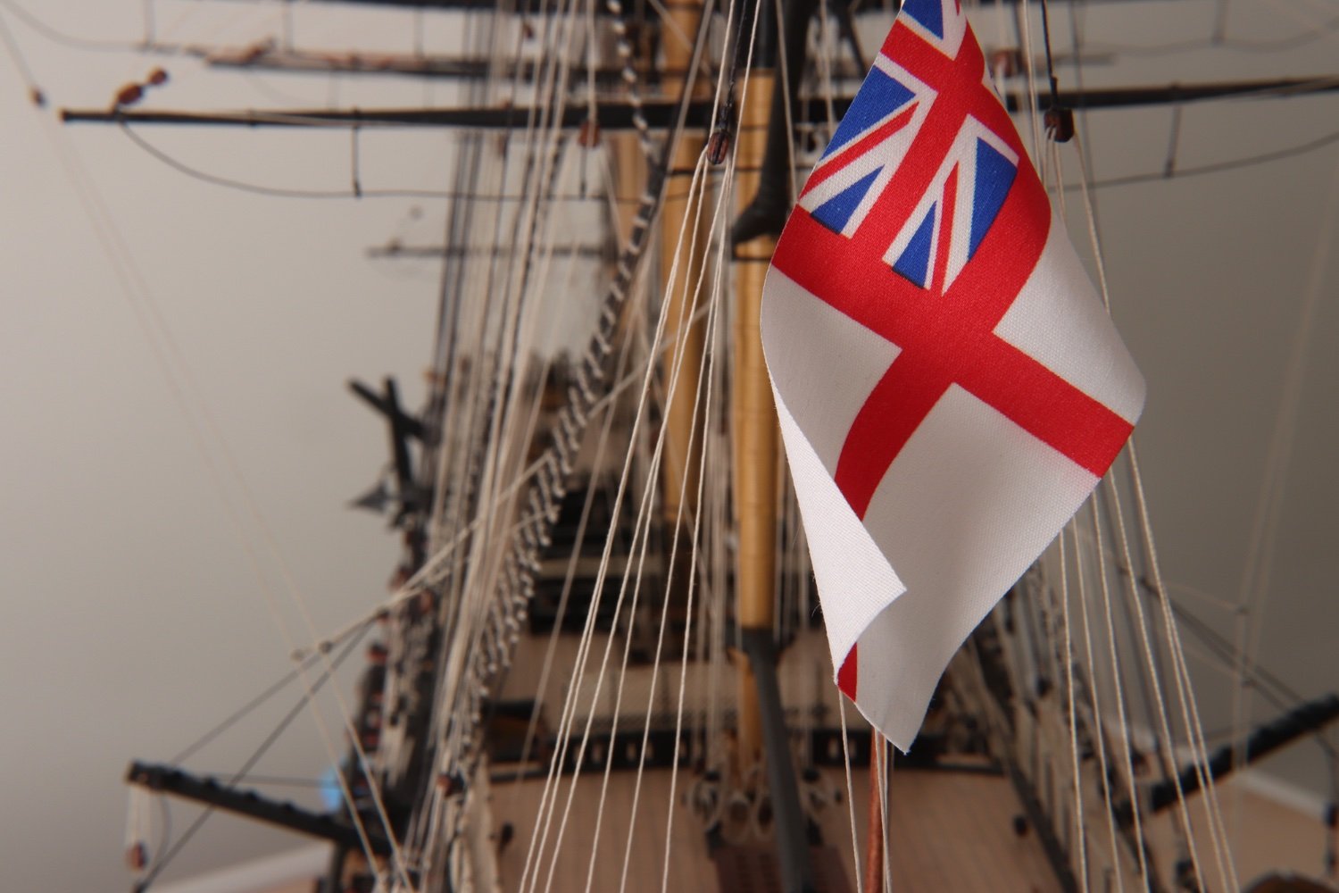
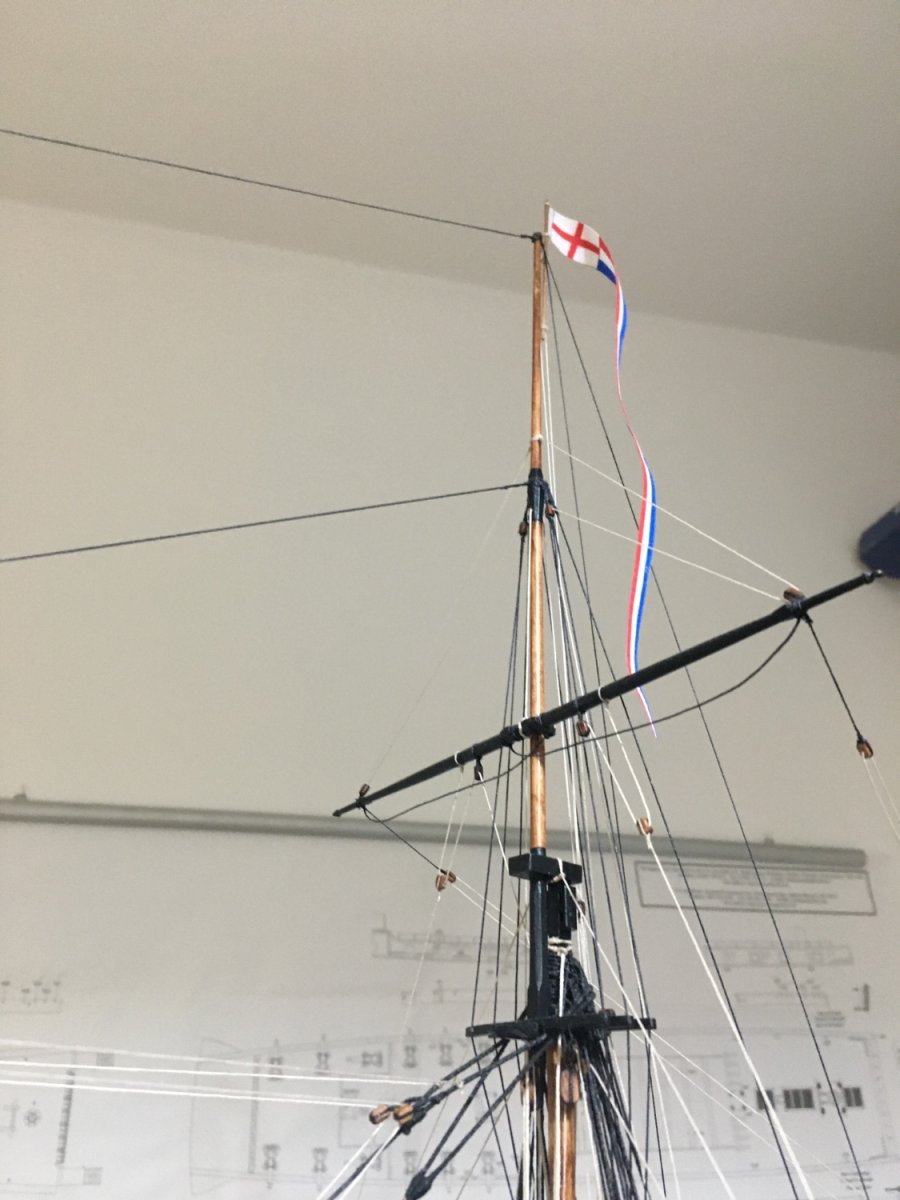
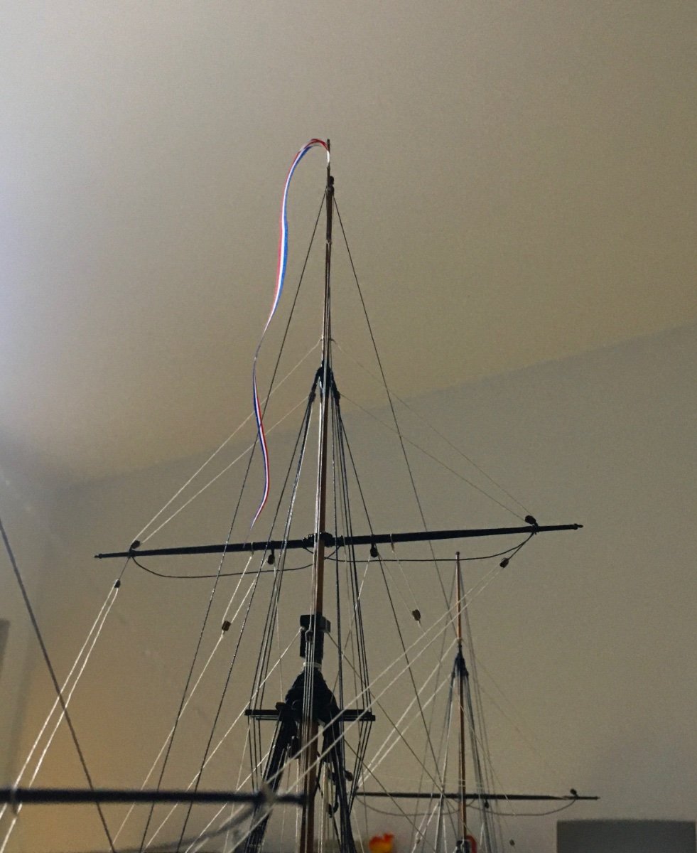
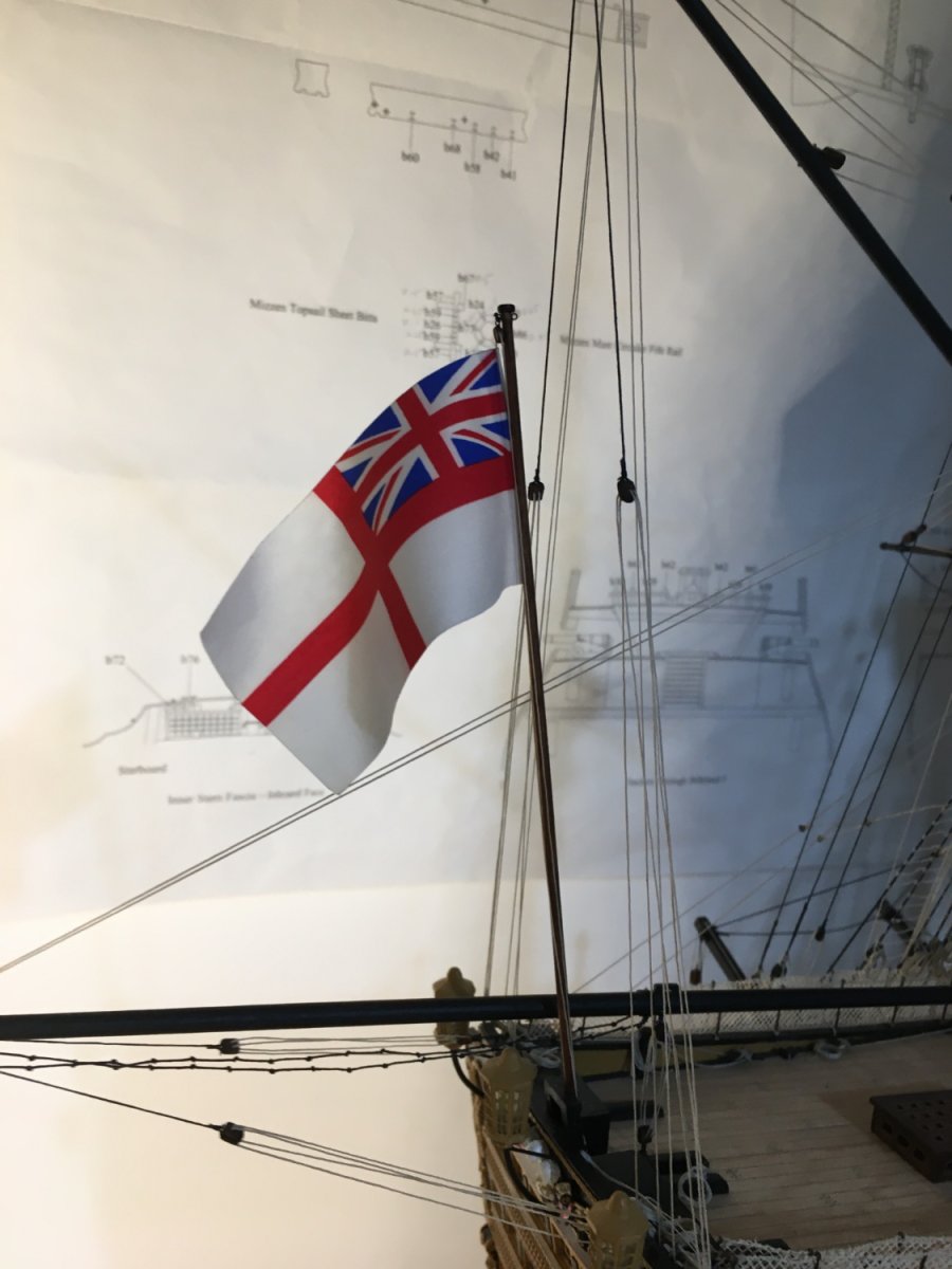
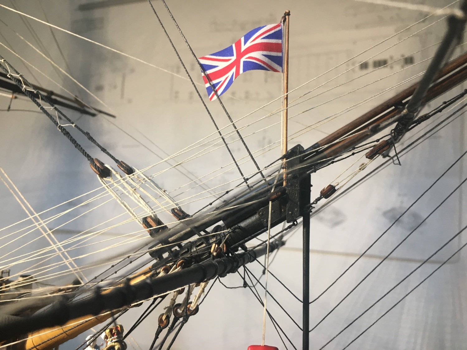
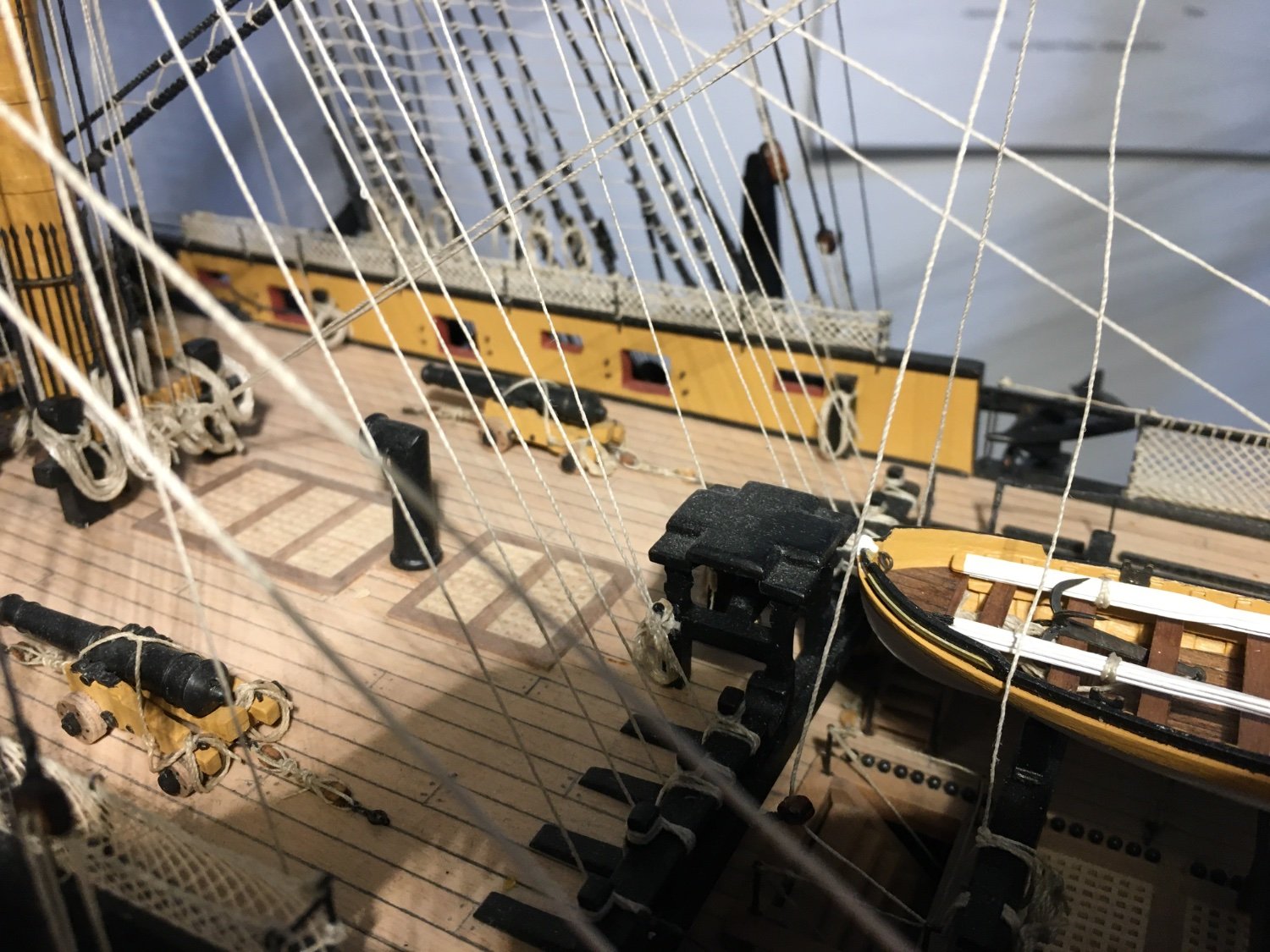
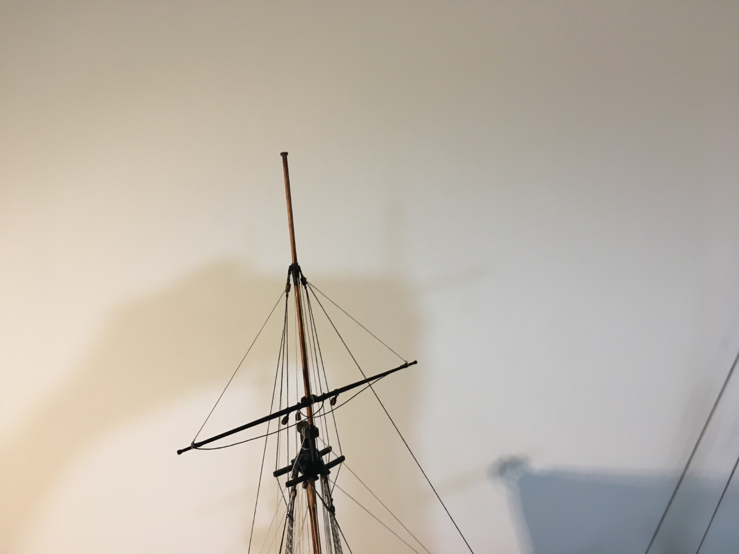
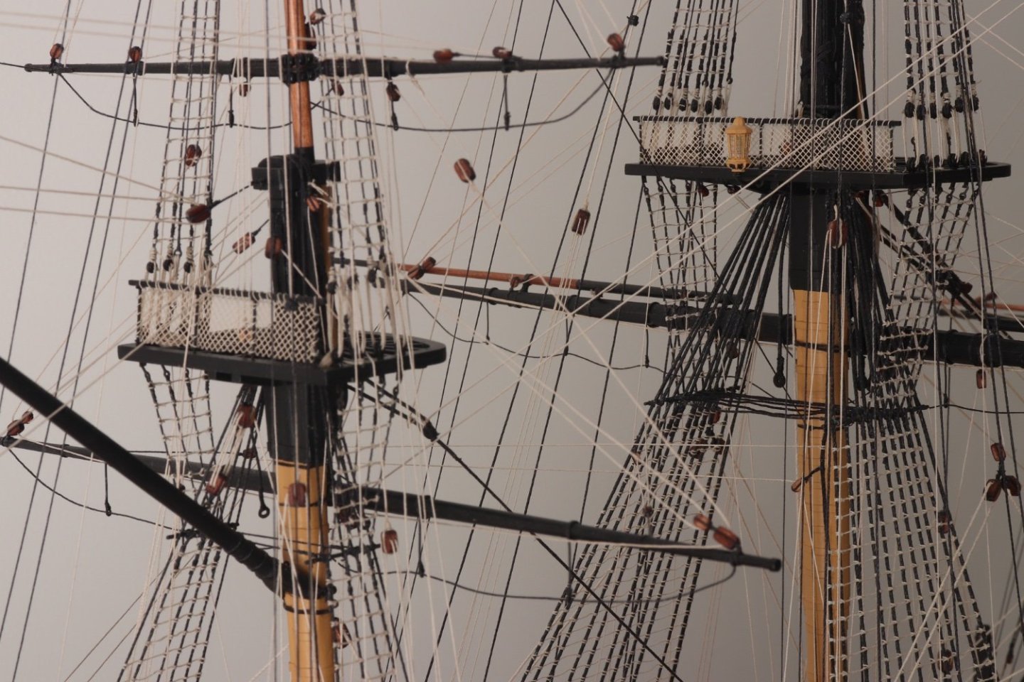
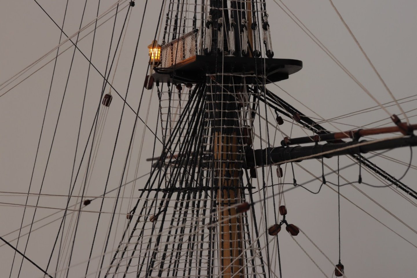
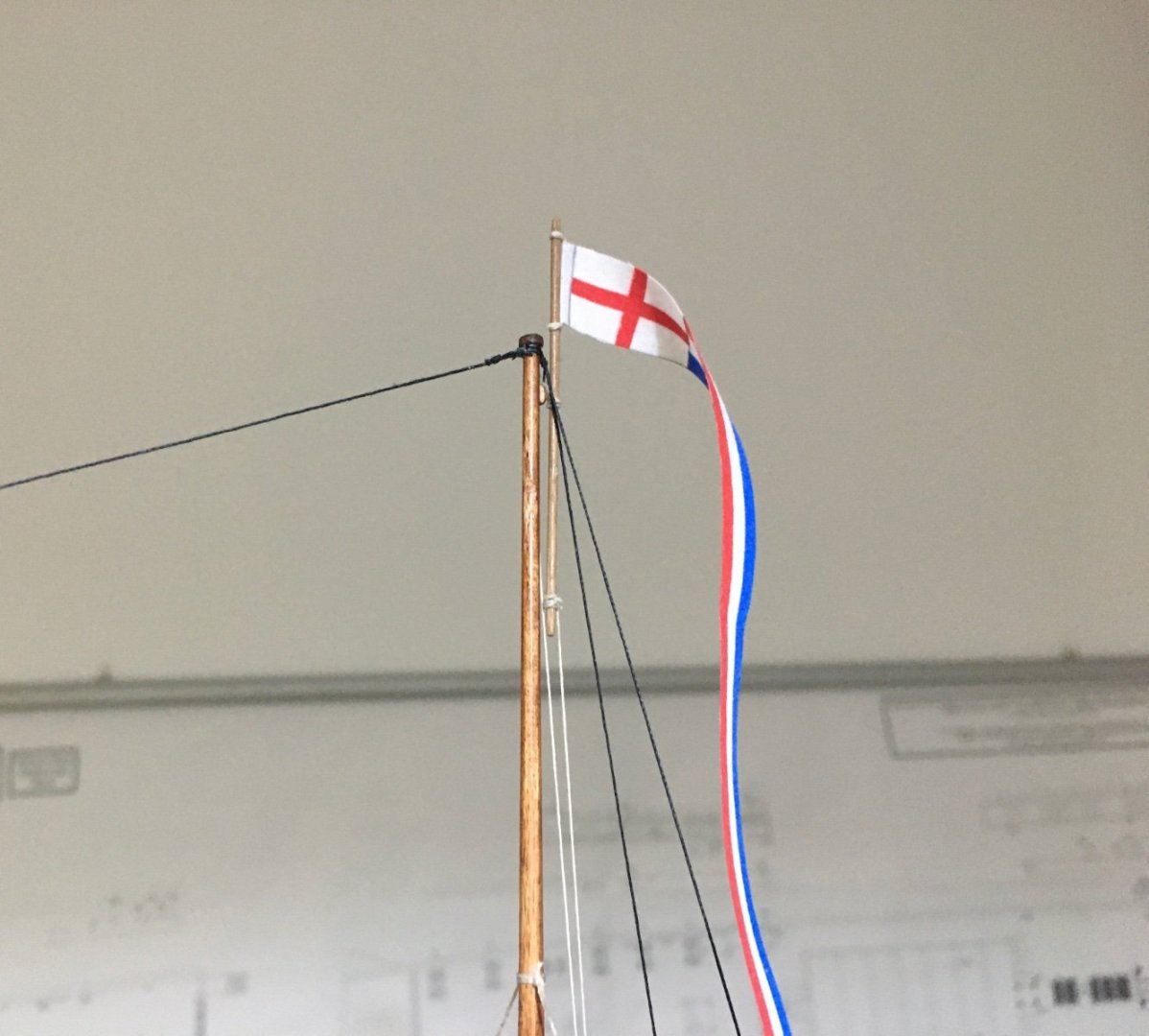
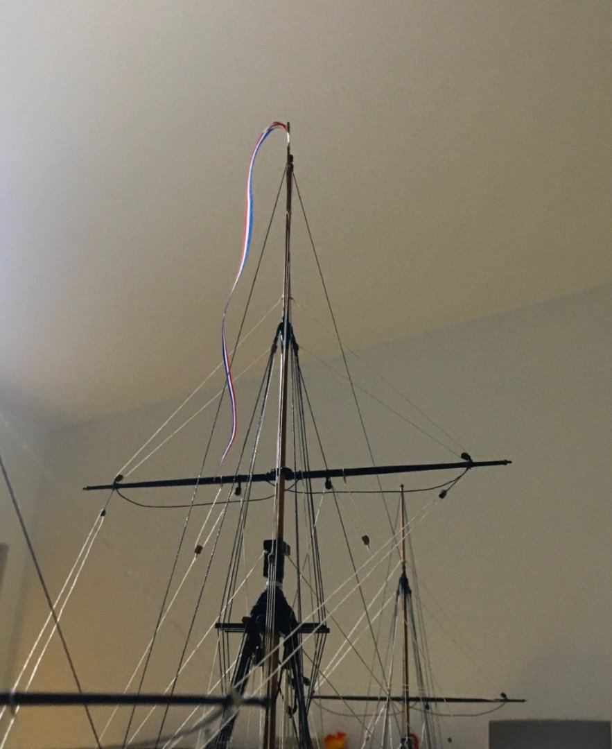
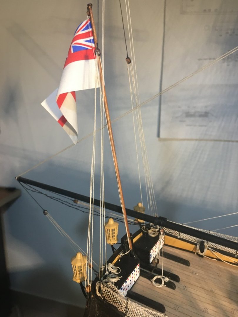
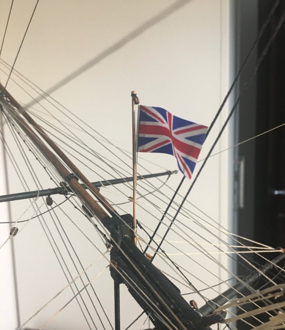
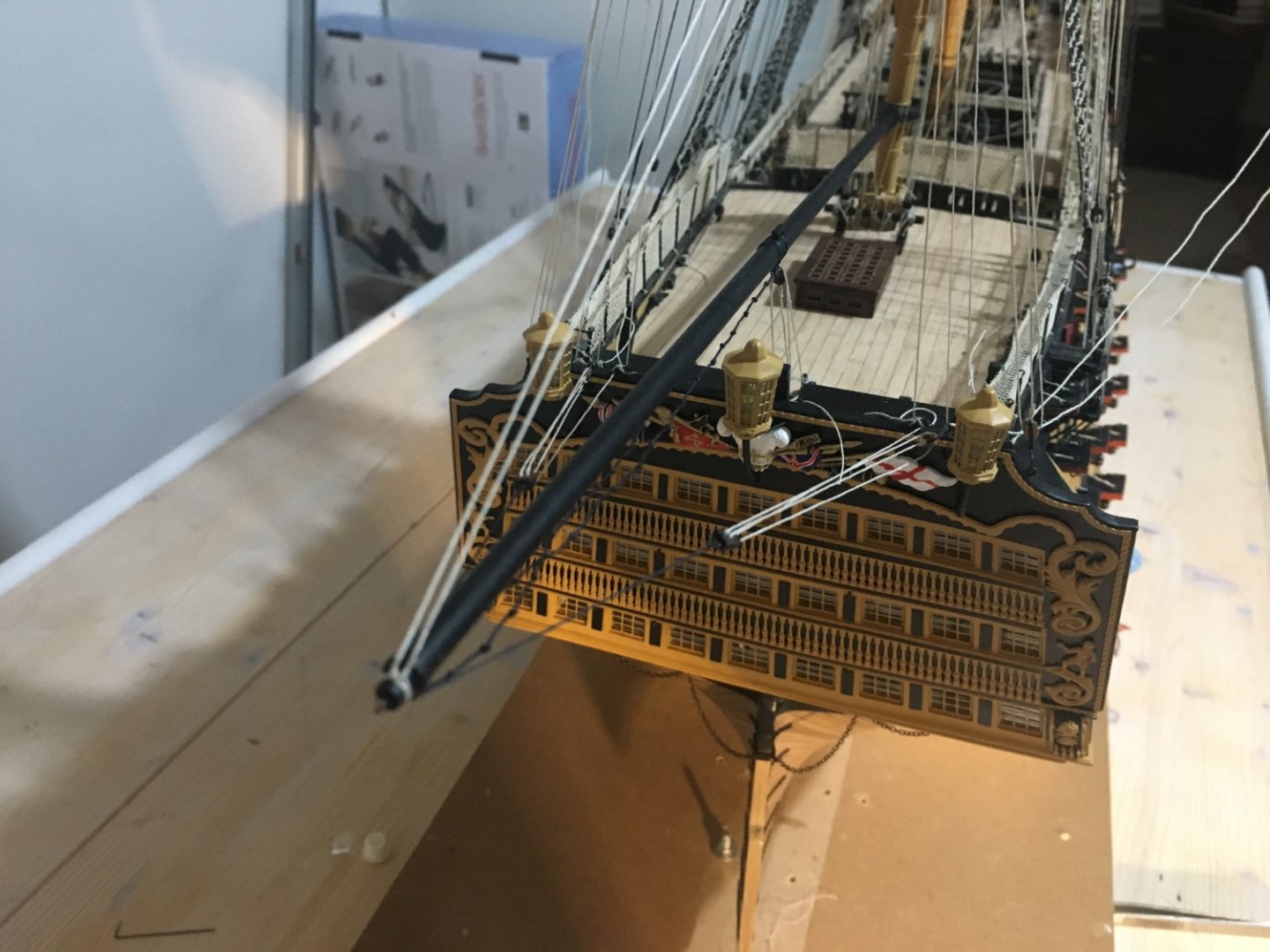
Thank you Ron, glad my build log is of some help to others like other build logs have been of great help to me. Case in point flying the pennant flag. I was wondering how to fit the pennant on the main mast and couldn't really find any details on the internet. Then I remembered seeing something on Gil Middleton's great build log. Gil had details how pig sticks were used and I used the same idea. The pig stick is hoisted above the mast head so that the flag is not fouled by the stays. The hoisting halyards are secured to the top. Also secured the kedge anchor on the starboard mizzen channel. Some more finishing touches to go. Robert

- 521 replies
-
- 12
-
-
- caldercraft
- victory
- (and 1 more)
-
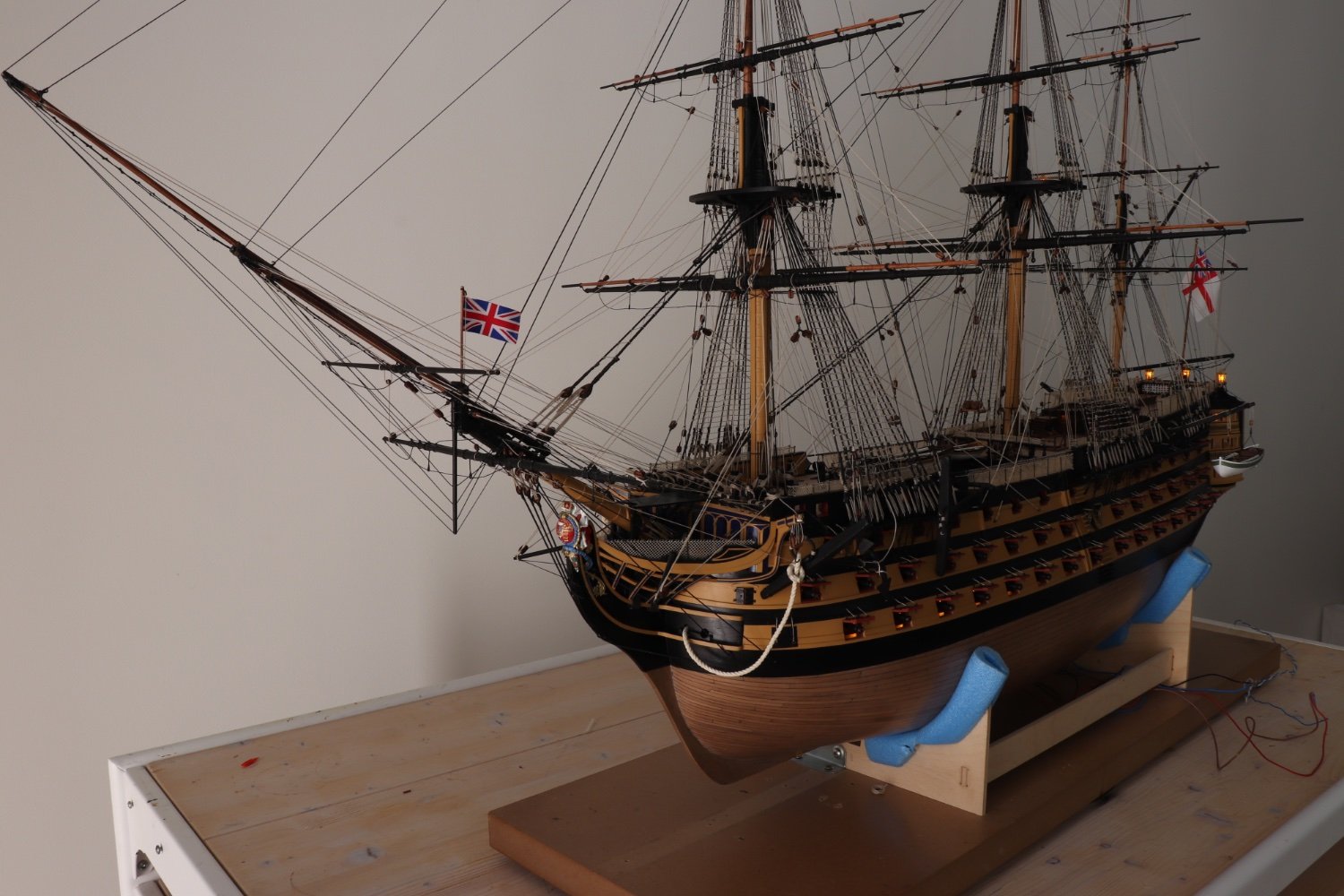
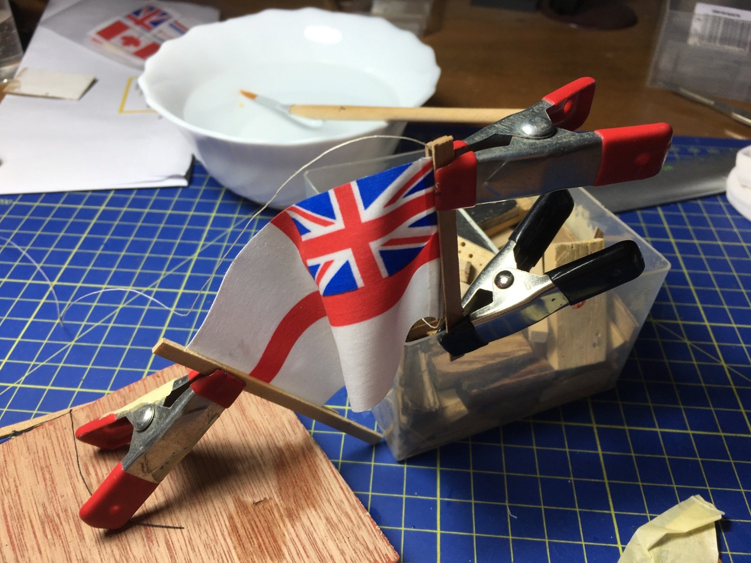
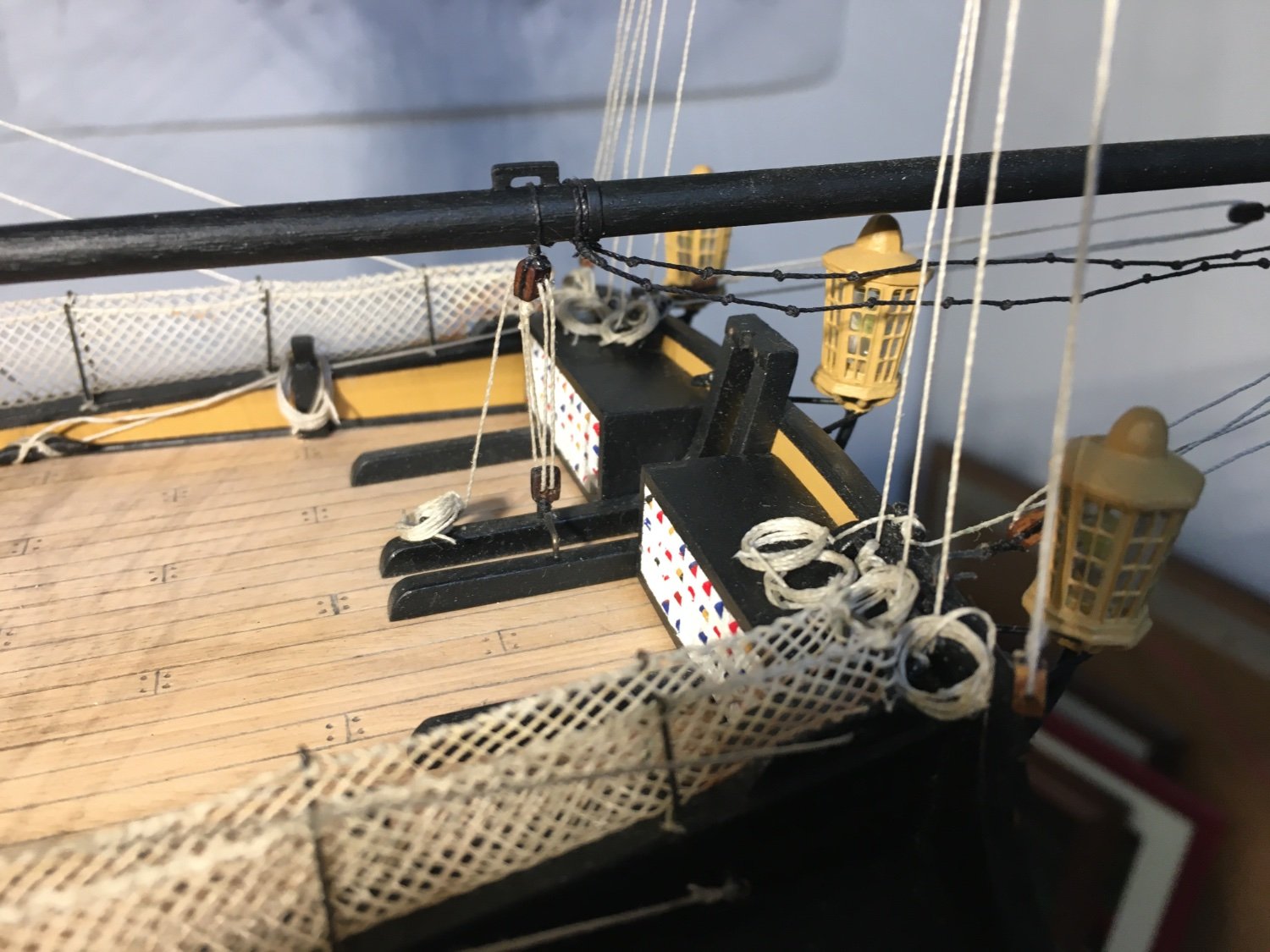
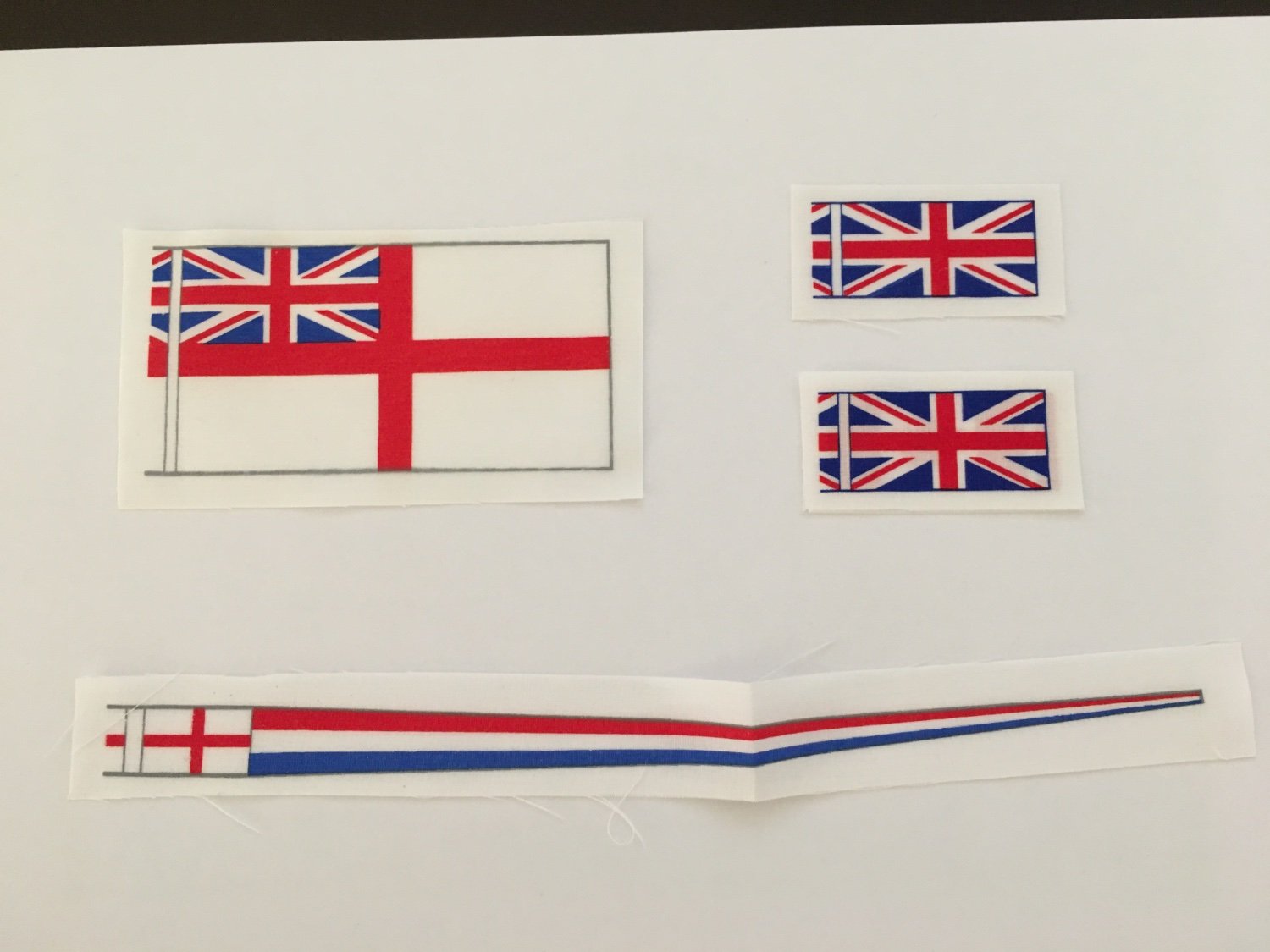
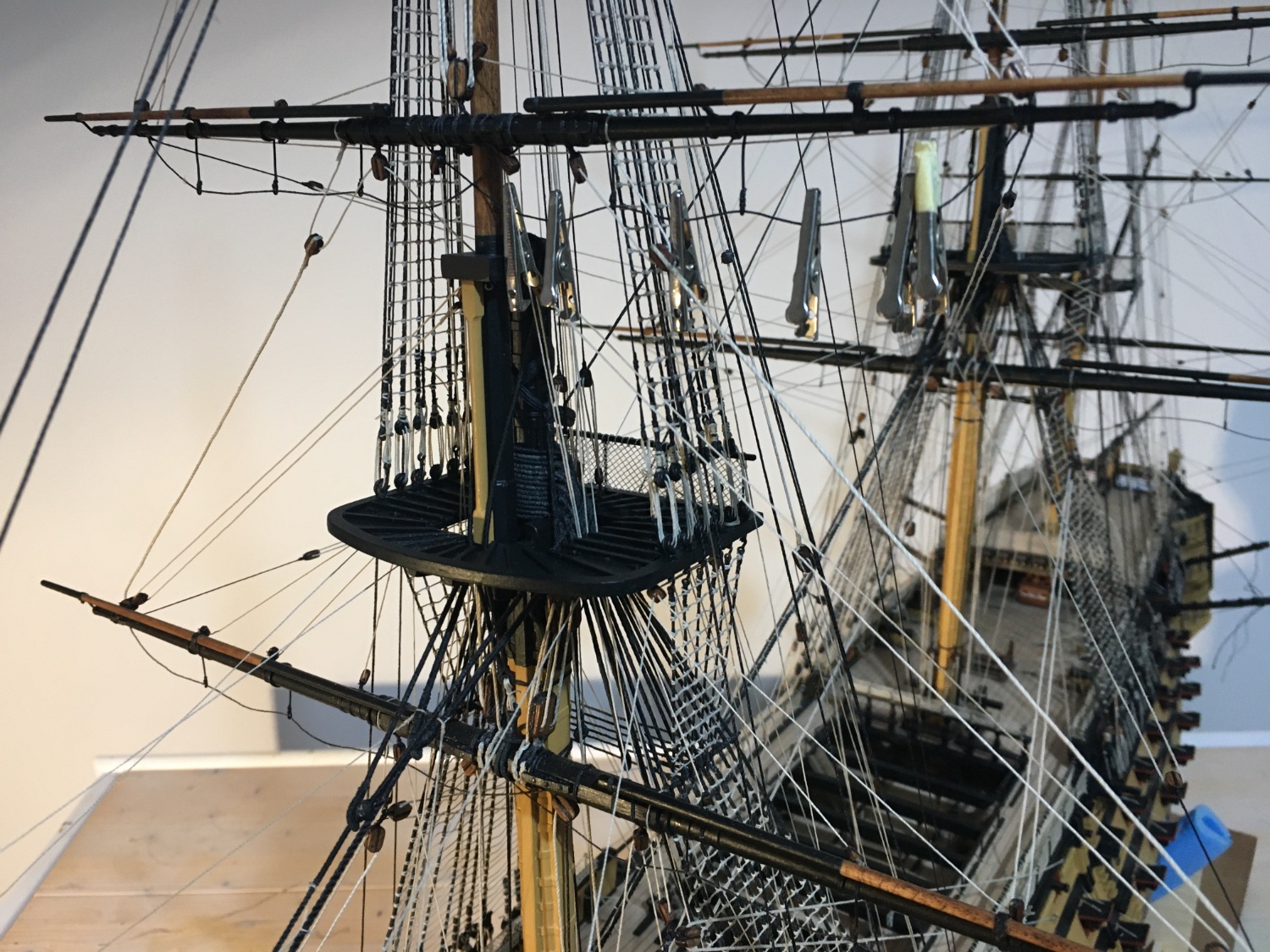
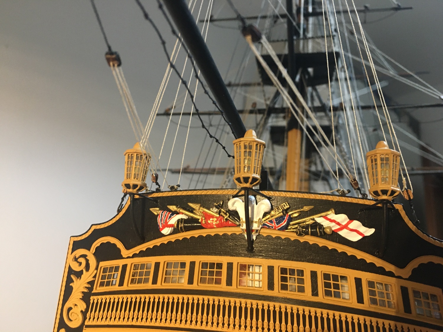
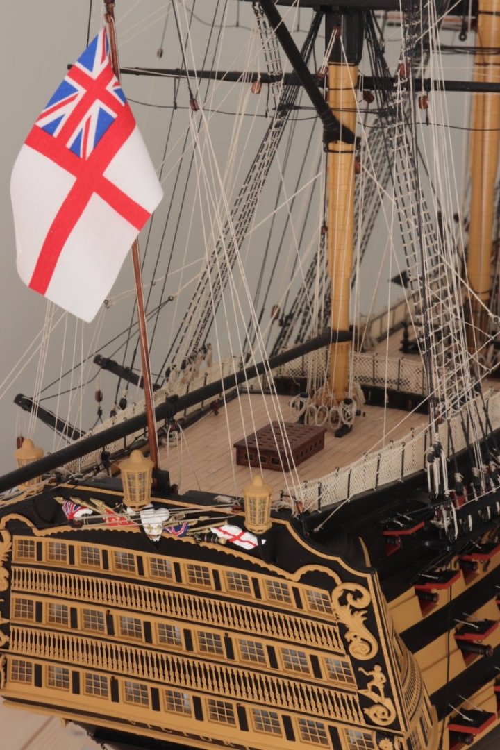
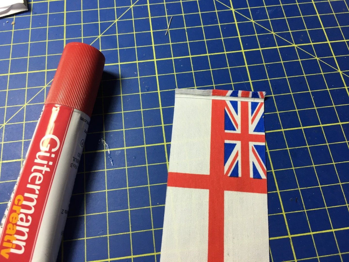
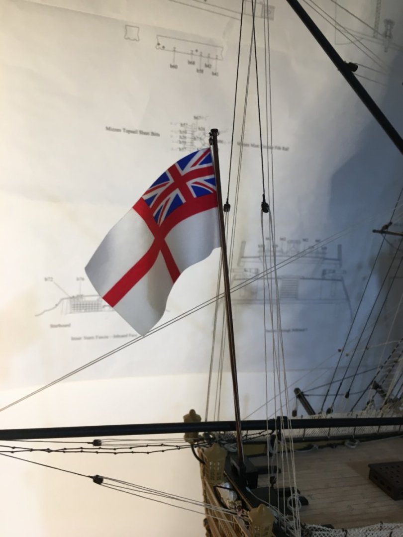
Thank you Ian and Graham. Getting closer to the finish. Fitted two flags and tried to make them look as realistic as possible. I used glue purposely for fabric. The brand is Guttermann, had used it on sails for another model, very good stuff. Didn't want to risk other glue, so for that very little bit I had to buy a new one, as the previous one I had, had dried up. Put glue on one side, placed the thread and attached the two faces. With a couple of clips I arranged the flag to look like it is sort of flying, then. with a brush I wetted it all with water and let it dry again. When I removed the clips it kept the shape. The ensign staff fitted in place and the ensign hoisted in place. The Union Jack also hoisted in place on the Jackstaff. Still have to fit the pennant. But first I have to check exactly where it goes and how it is fitted. Robert


- 521 replies
-
- 13
-
-
-
- caldercraft
- victory
- (and 1 more)
-
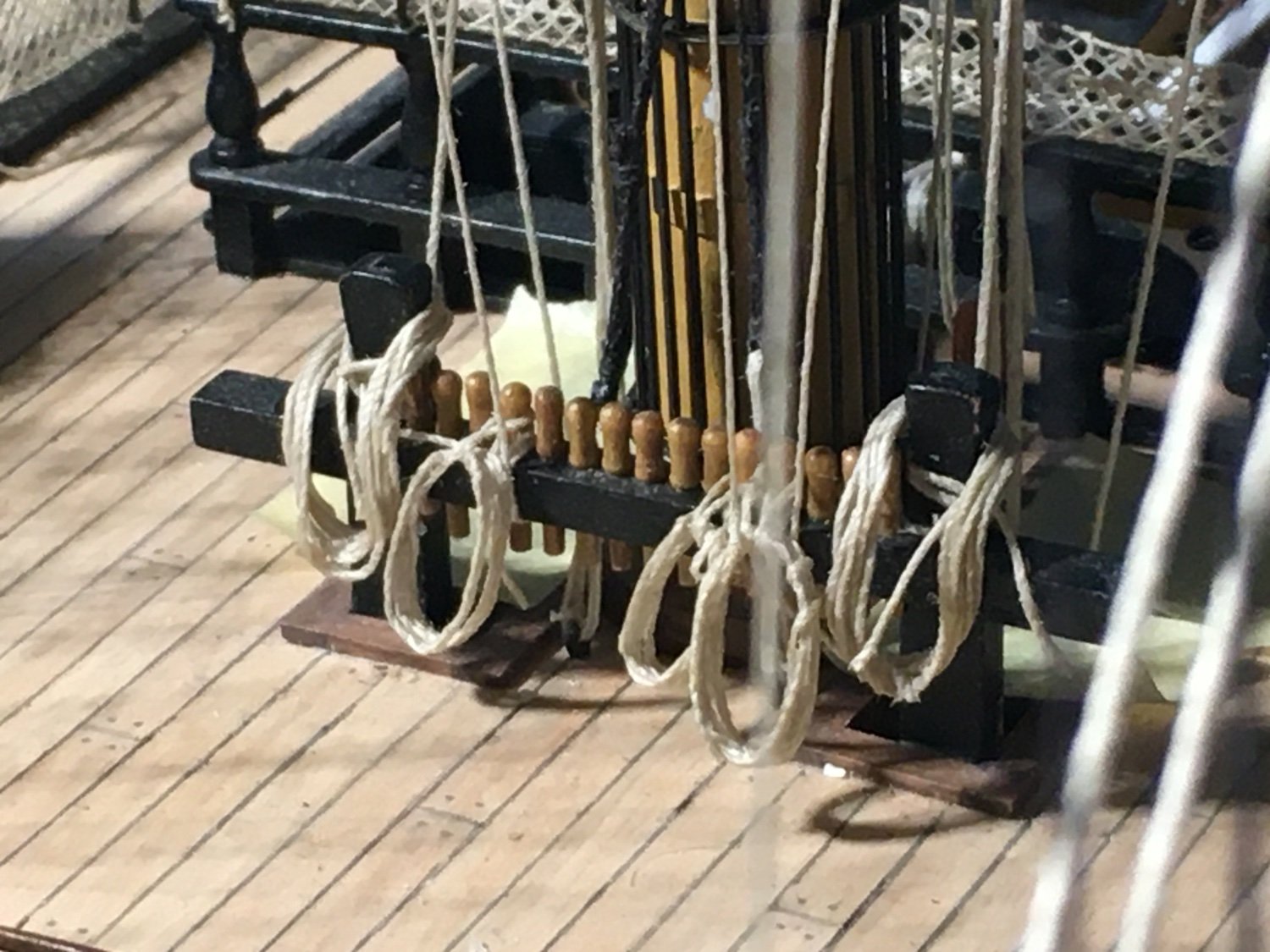
Long overdue update. I had other priorities and things have been moving extremely slow. When I found the time I was doing the rope coils. Here are a few images. I have ordered and received some flags which I will put up soon. So basically a few more coils, the flags, some fine rigging adjustments, a good cleanup and the Victory should be finished. Robert


- 521 replies
-
- 11
-
-
-
- caldercraft
- victory
- (and 1 more)
-
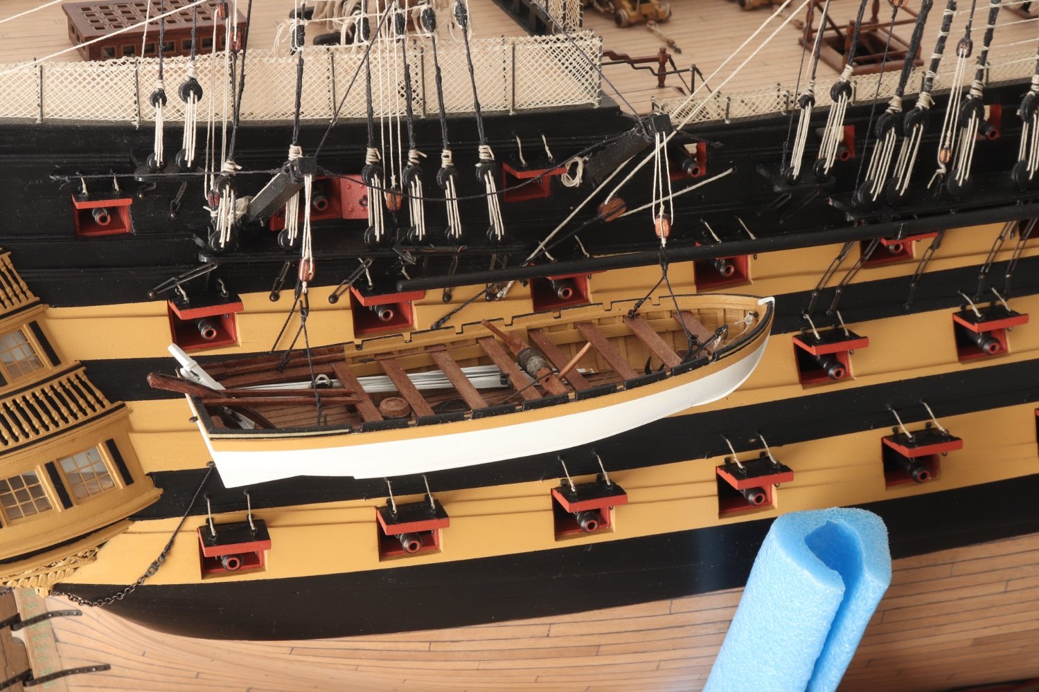
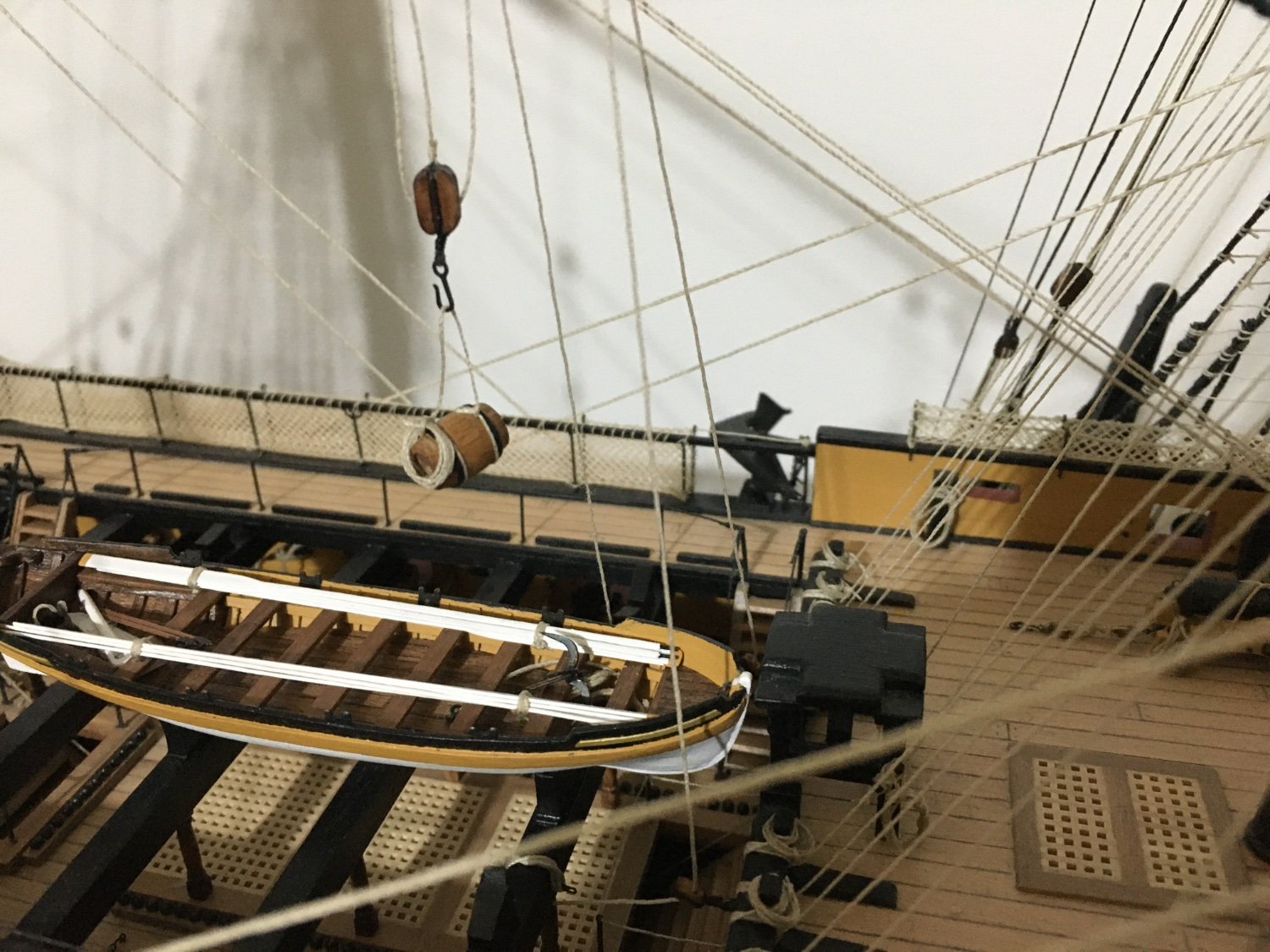
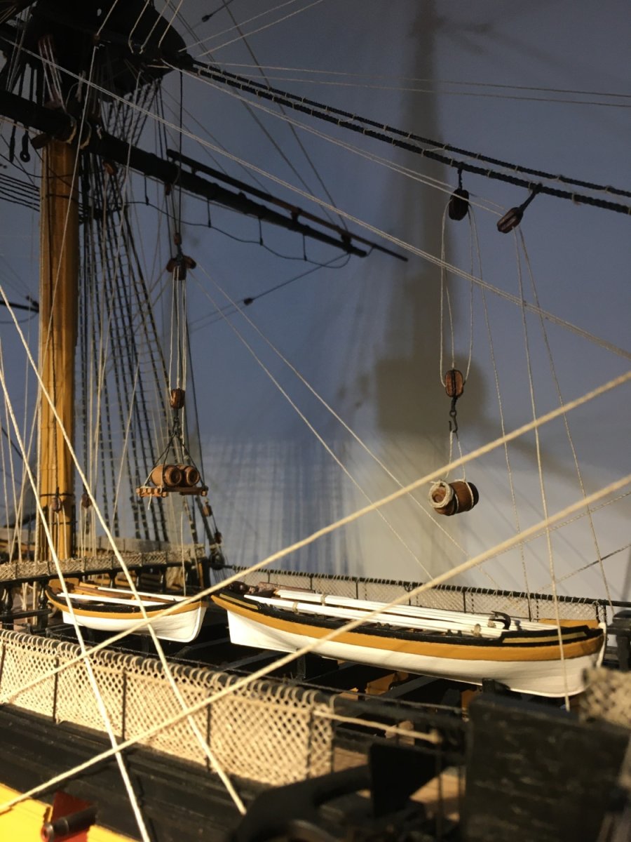
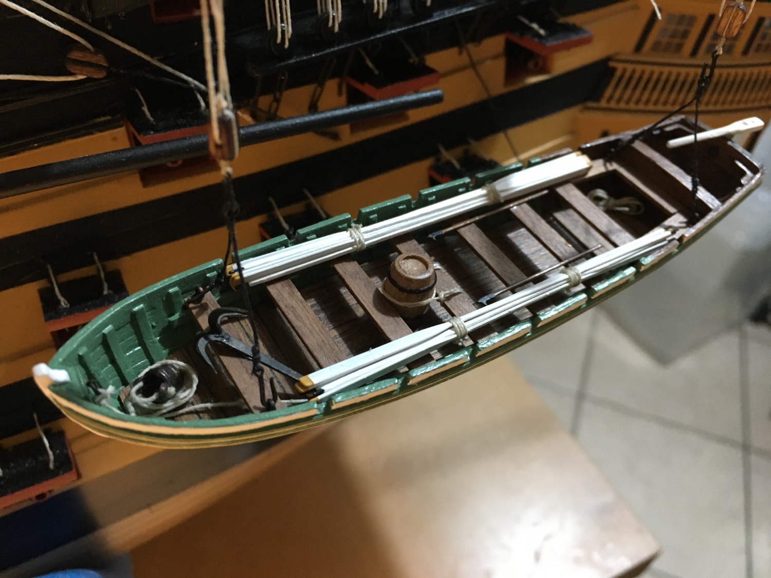
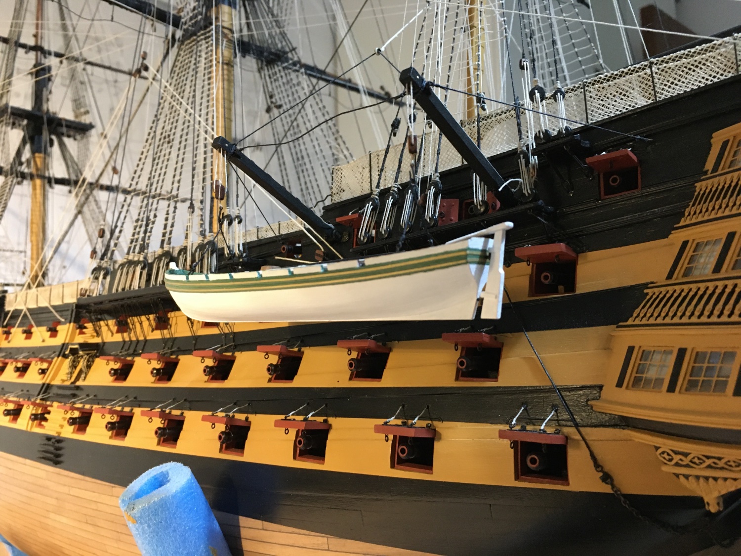
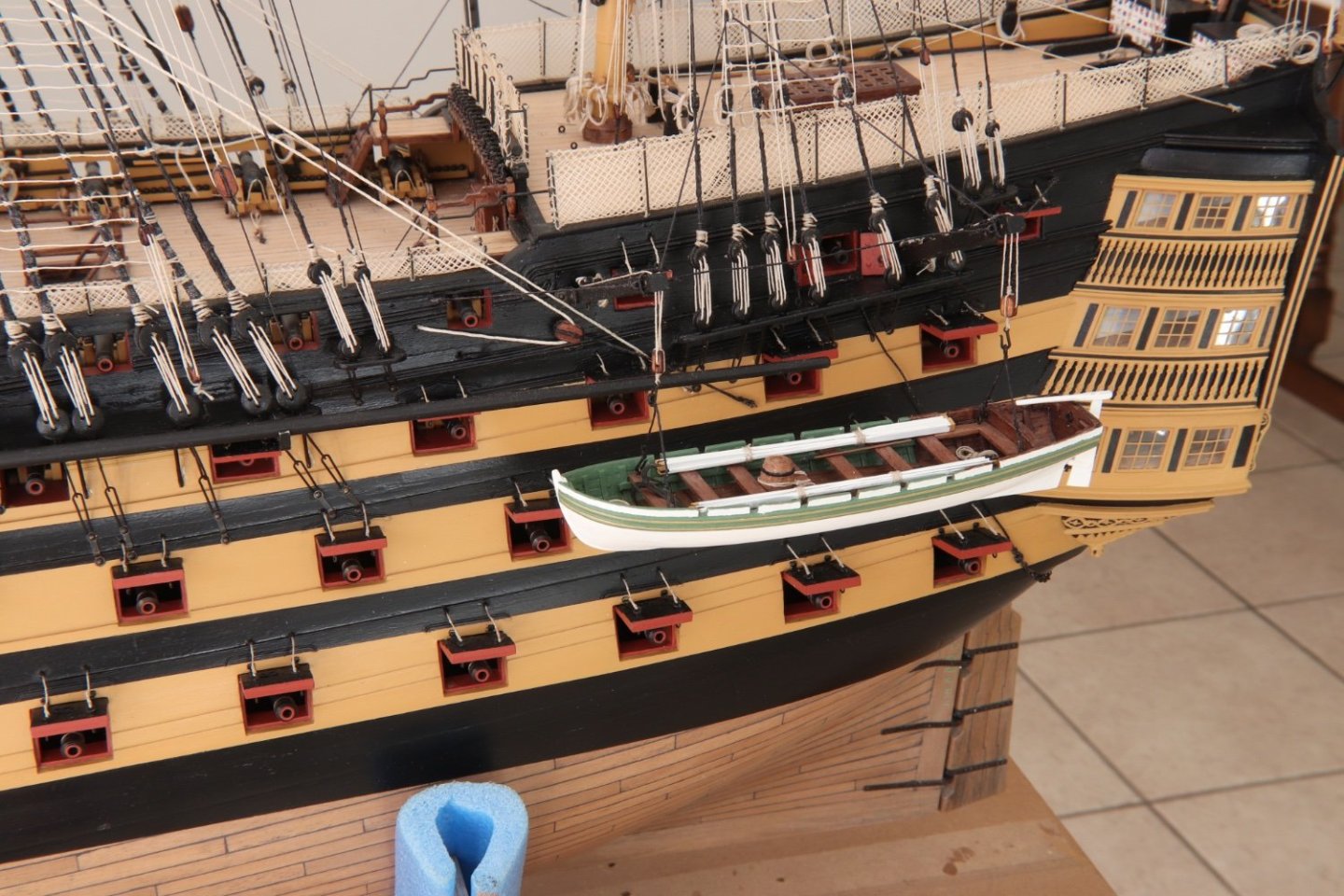
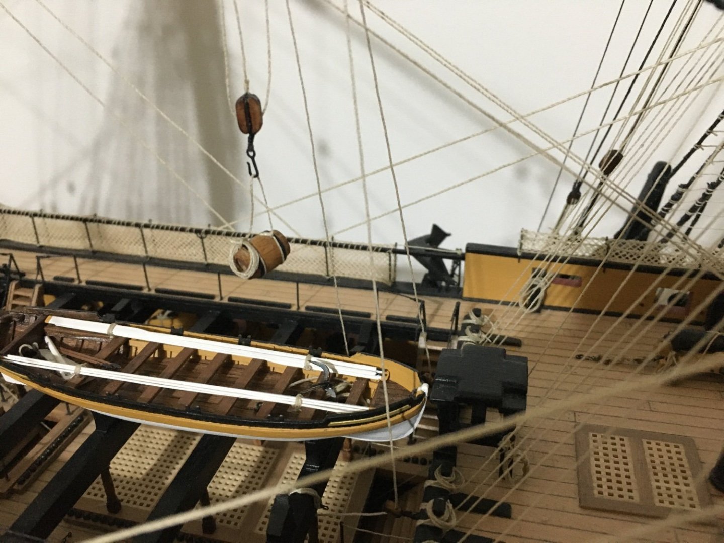
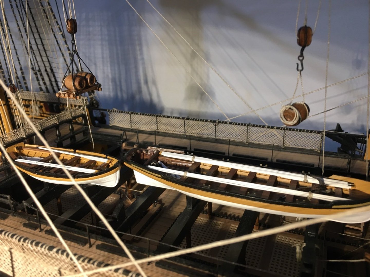
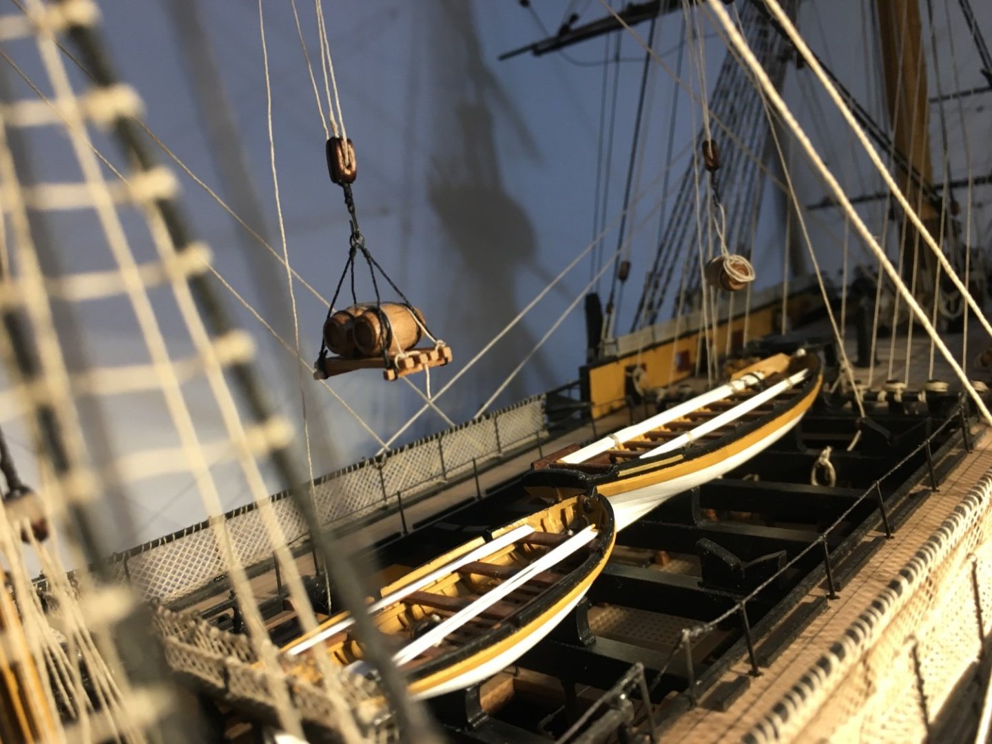
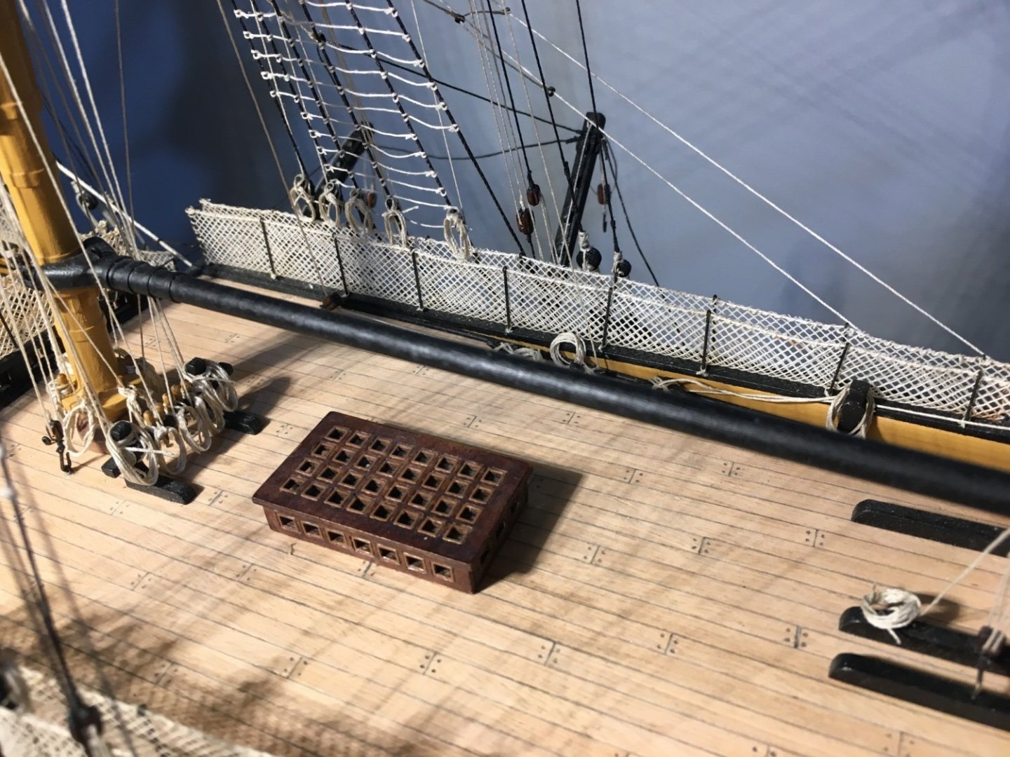
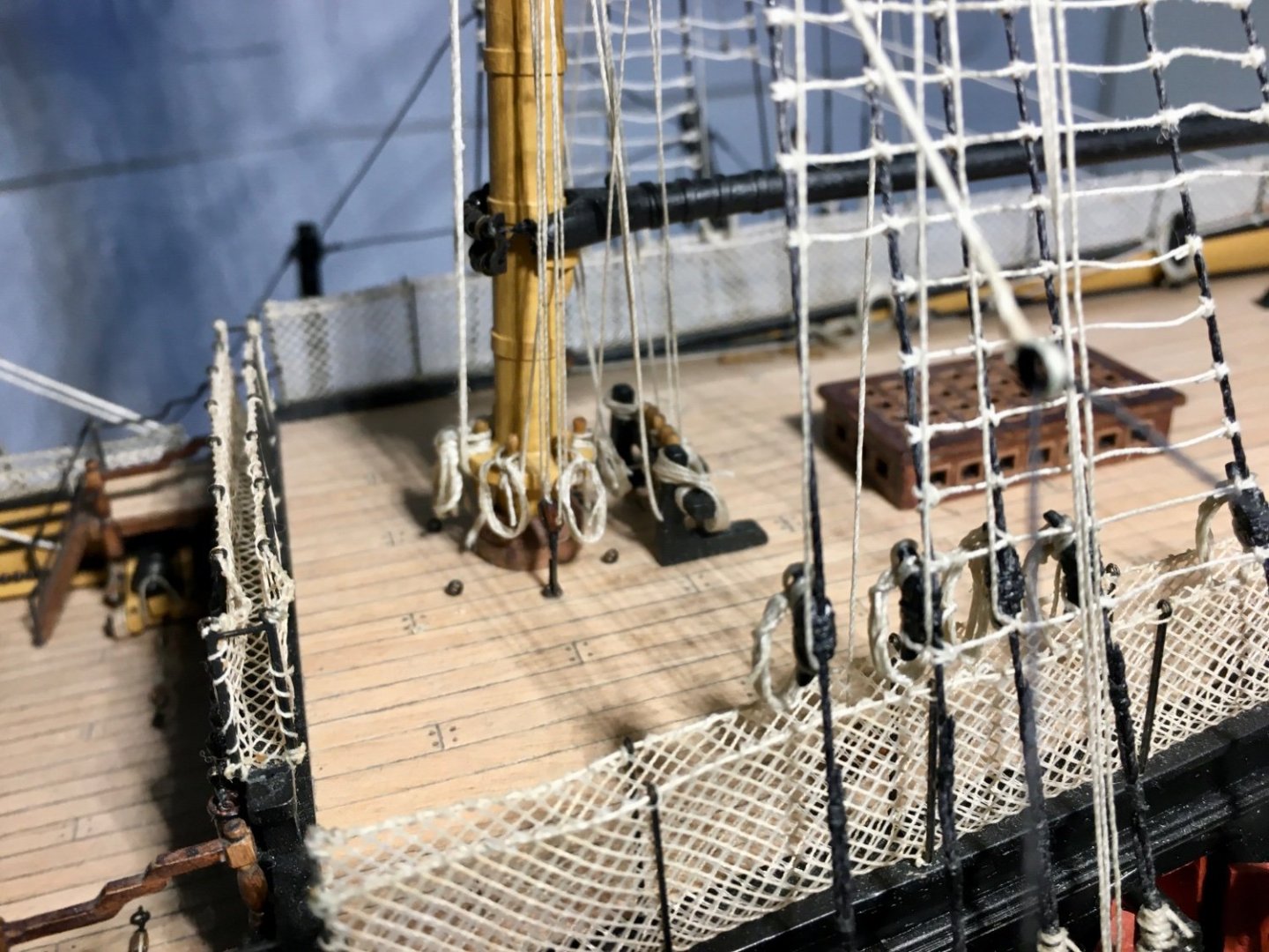
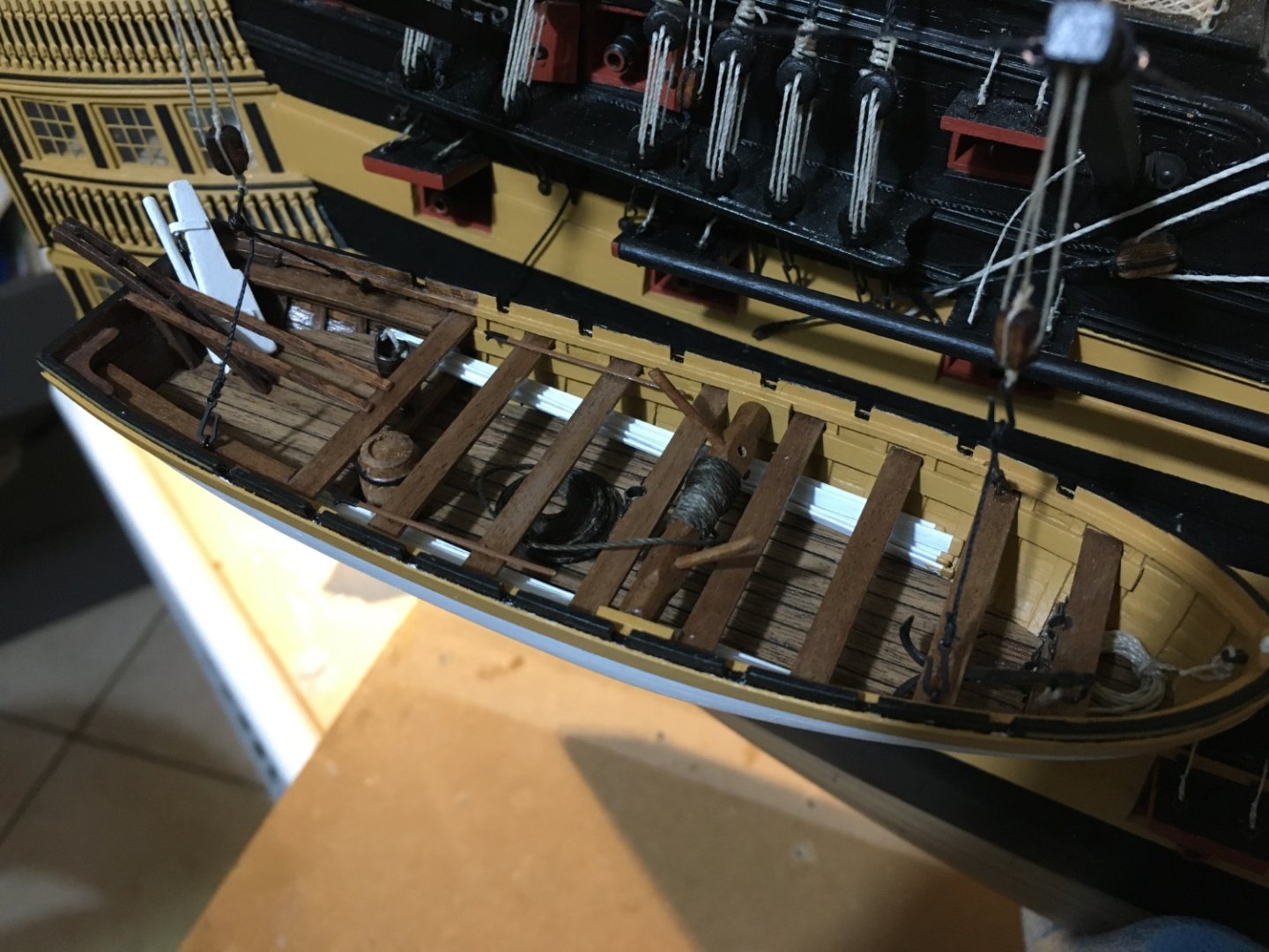
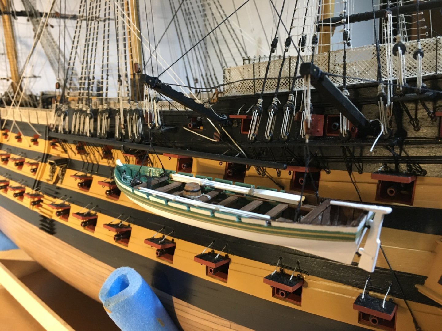
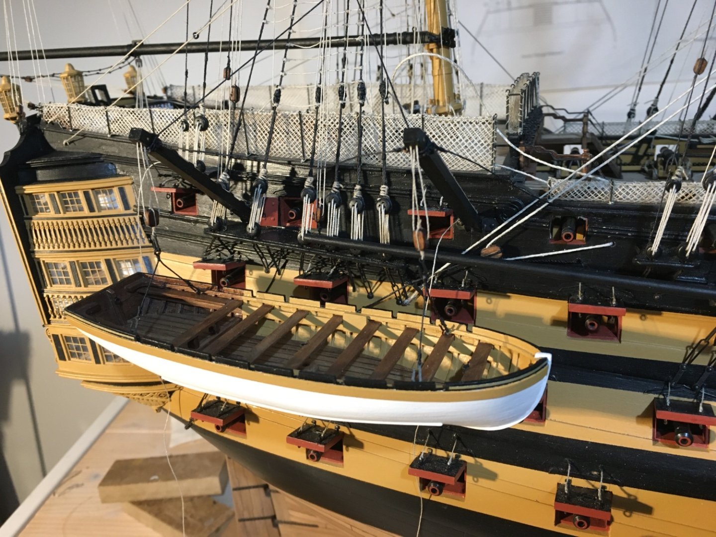
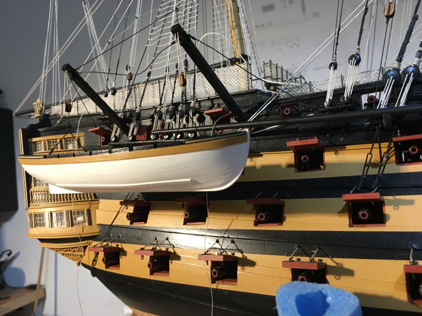
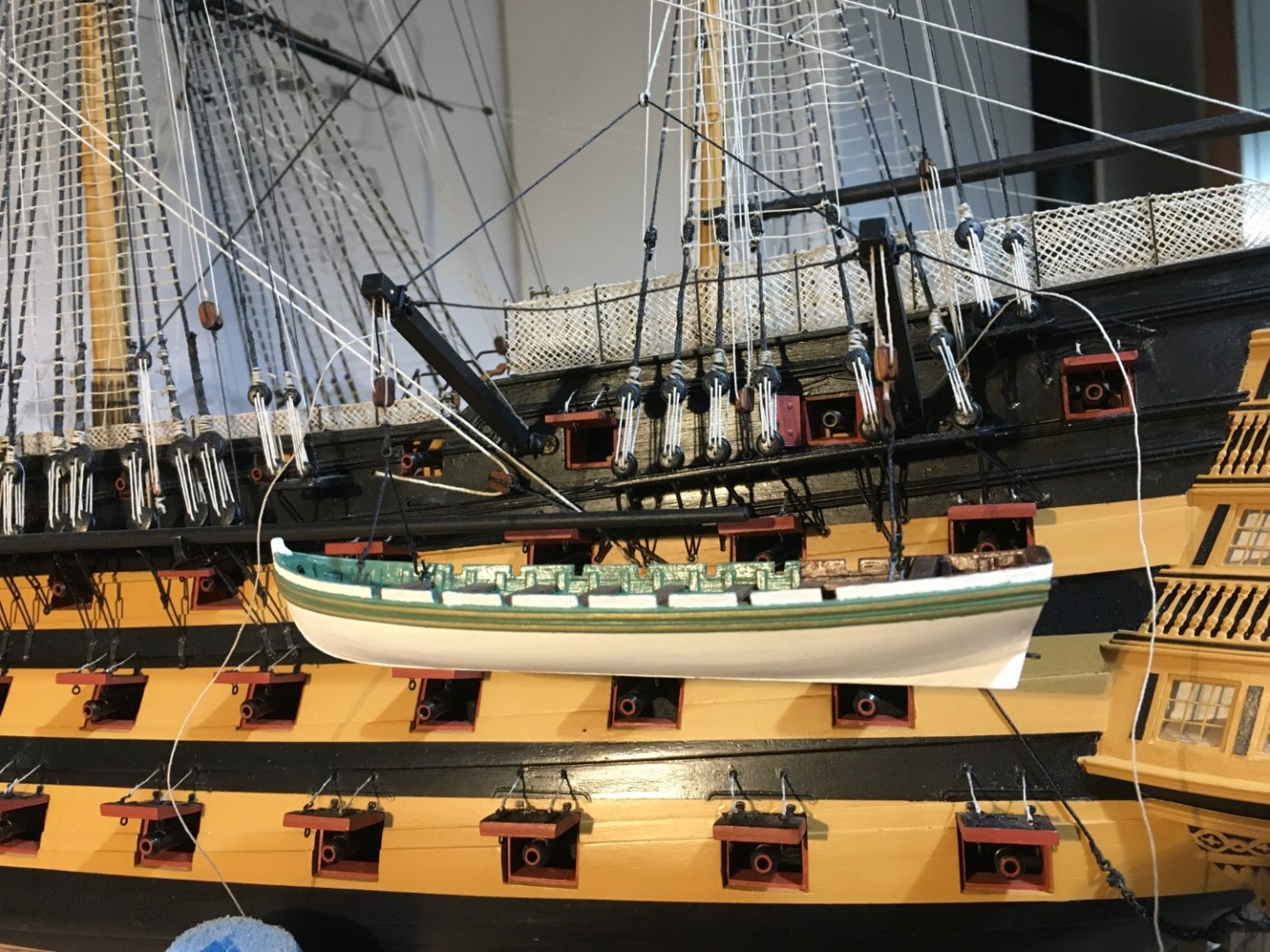
More work on the boats on the Davits. I fitted the accessories in the boats. Apart from the once supplied with the kit I added some, such as the bucket and the barrel. The Launch The Barge Robert


- 521 replies
-
- 14
-
-
-
- caldercraft
- victory
- (and 1 more)
-
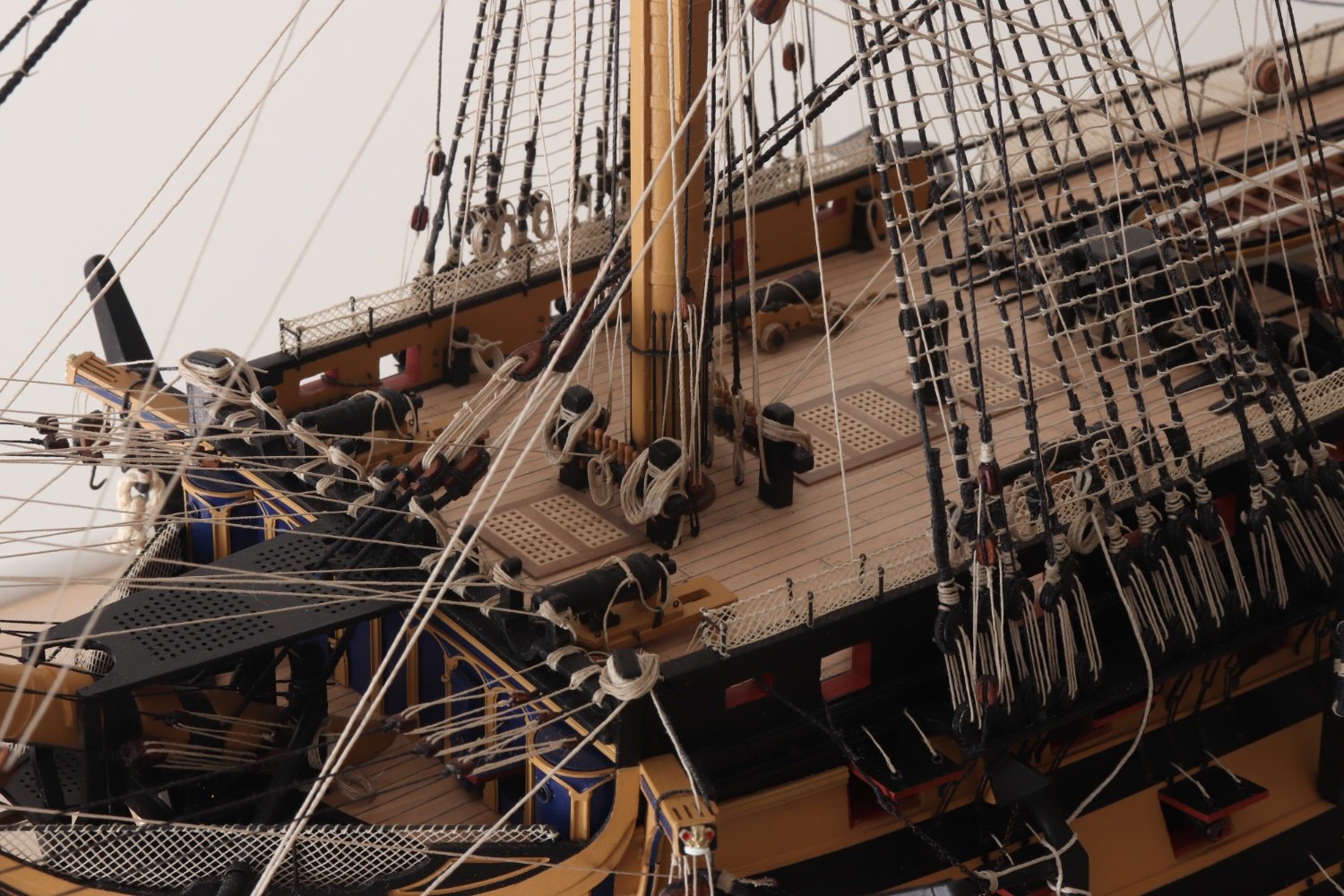
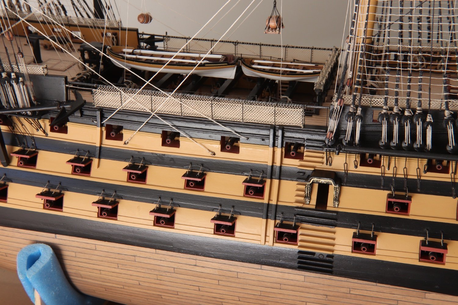
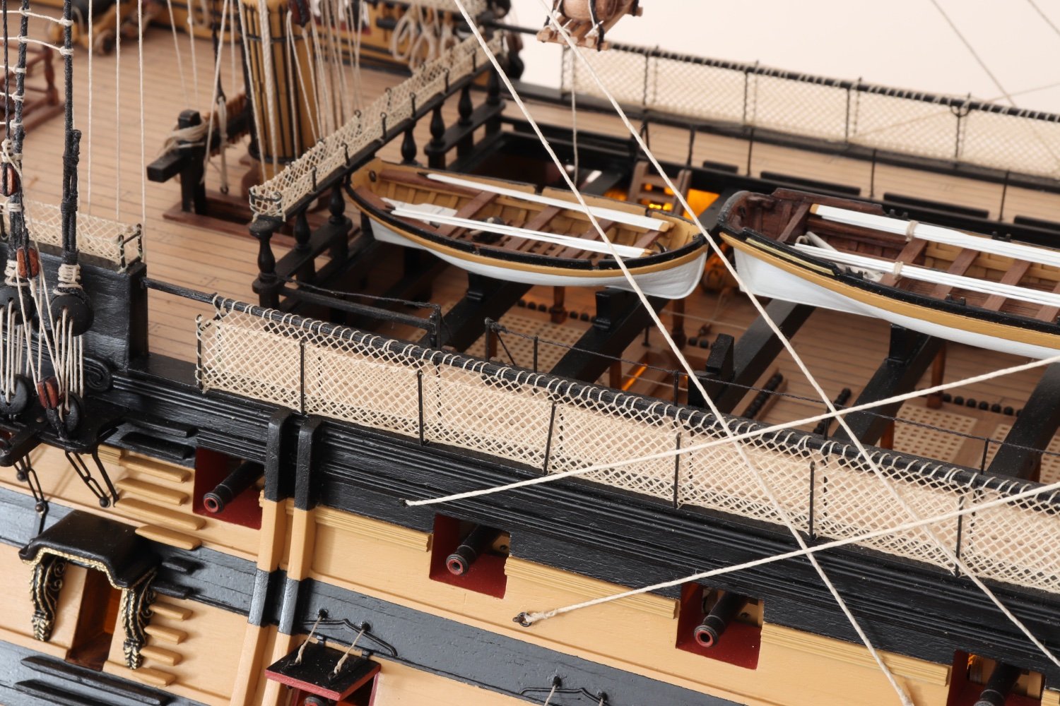
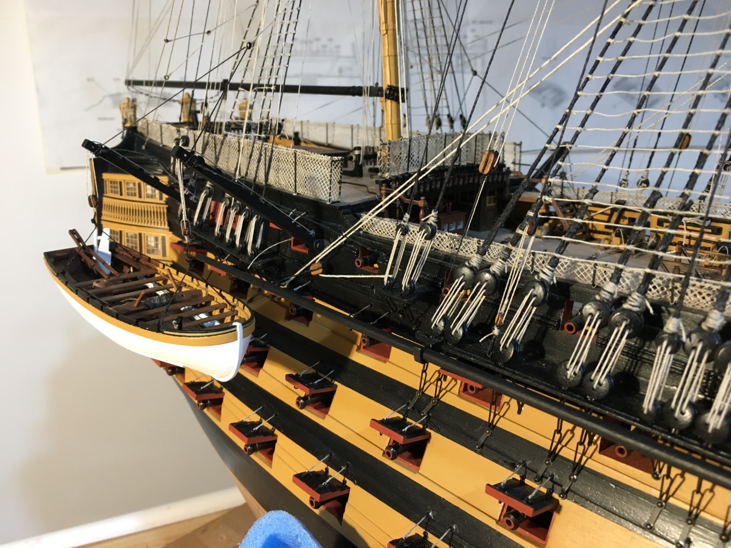
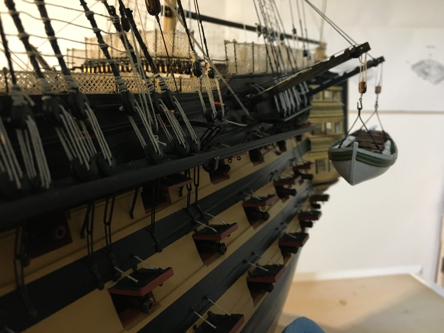
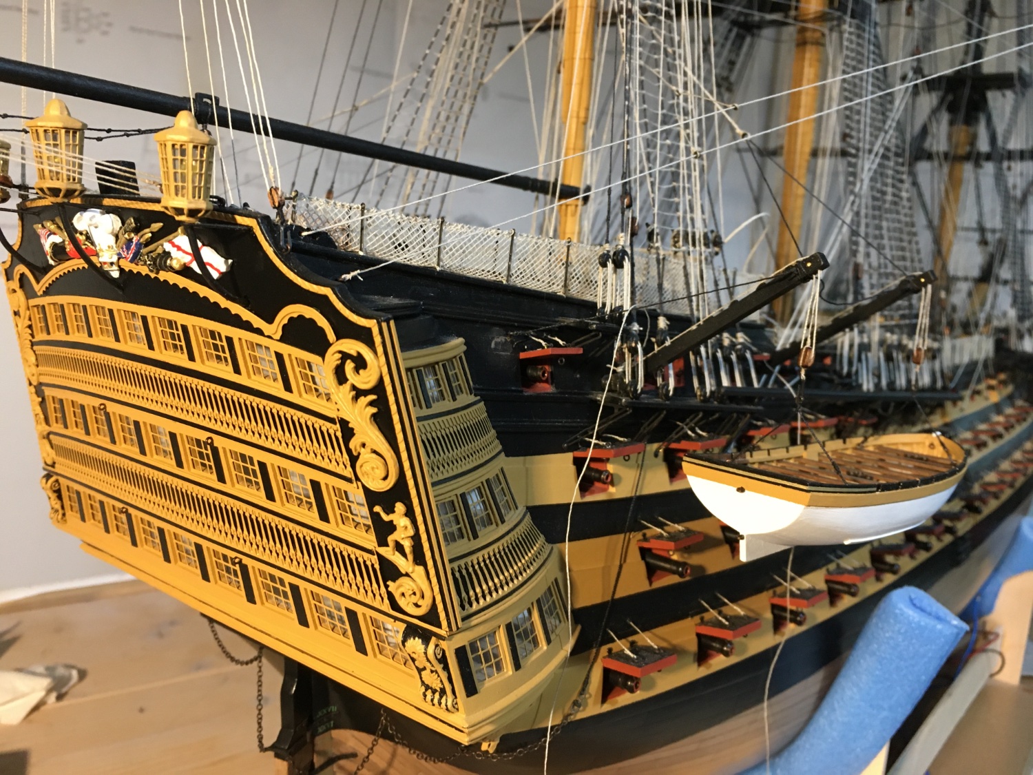
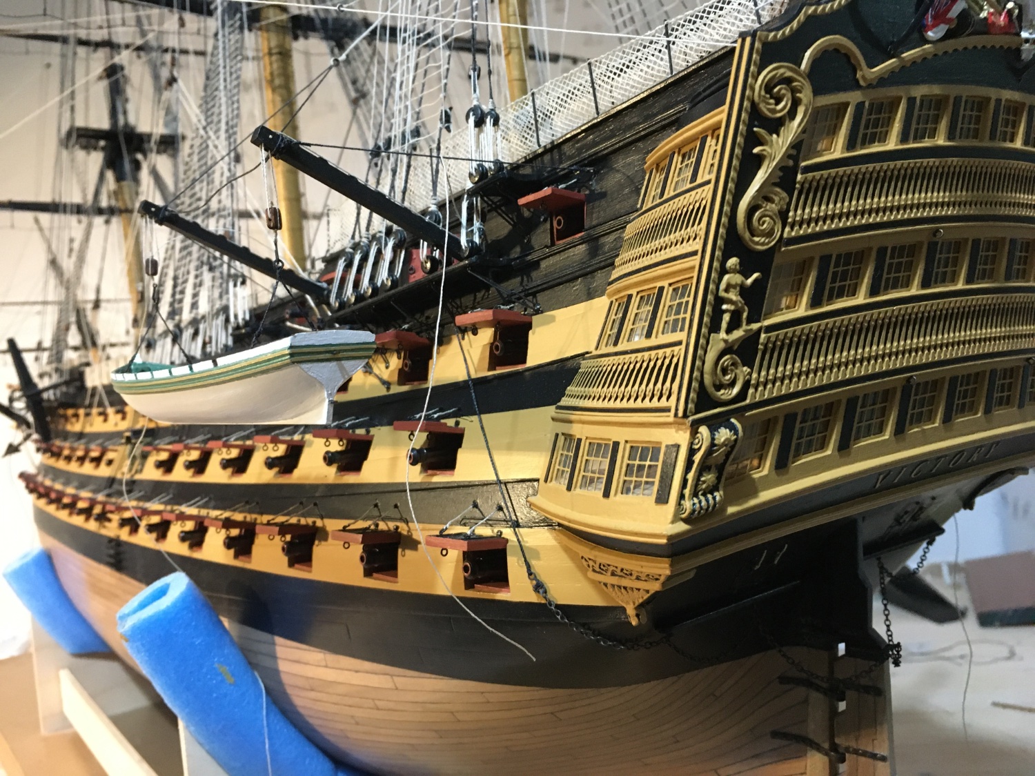
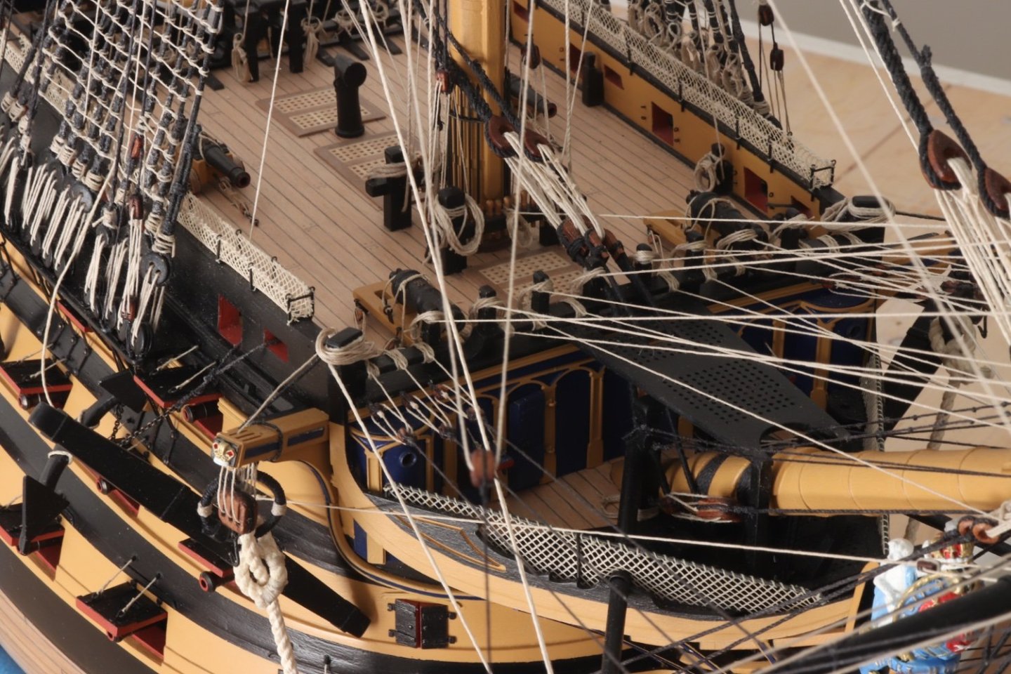
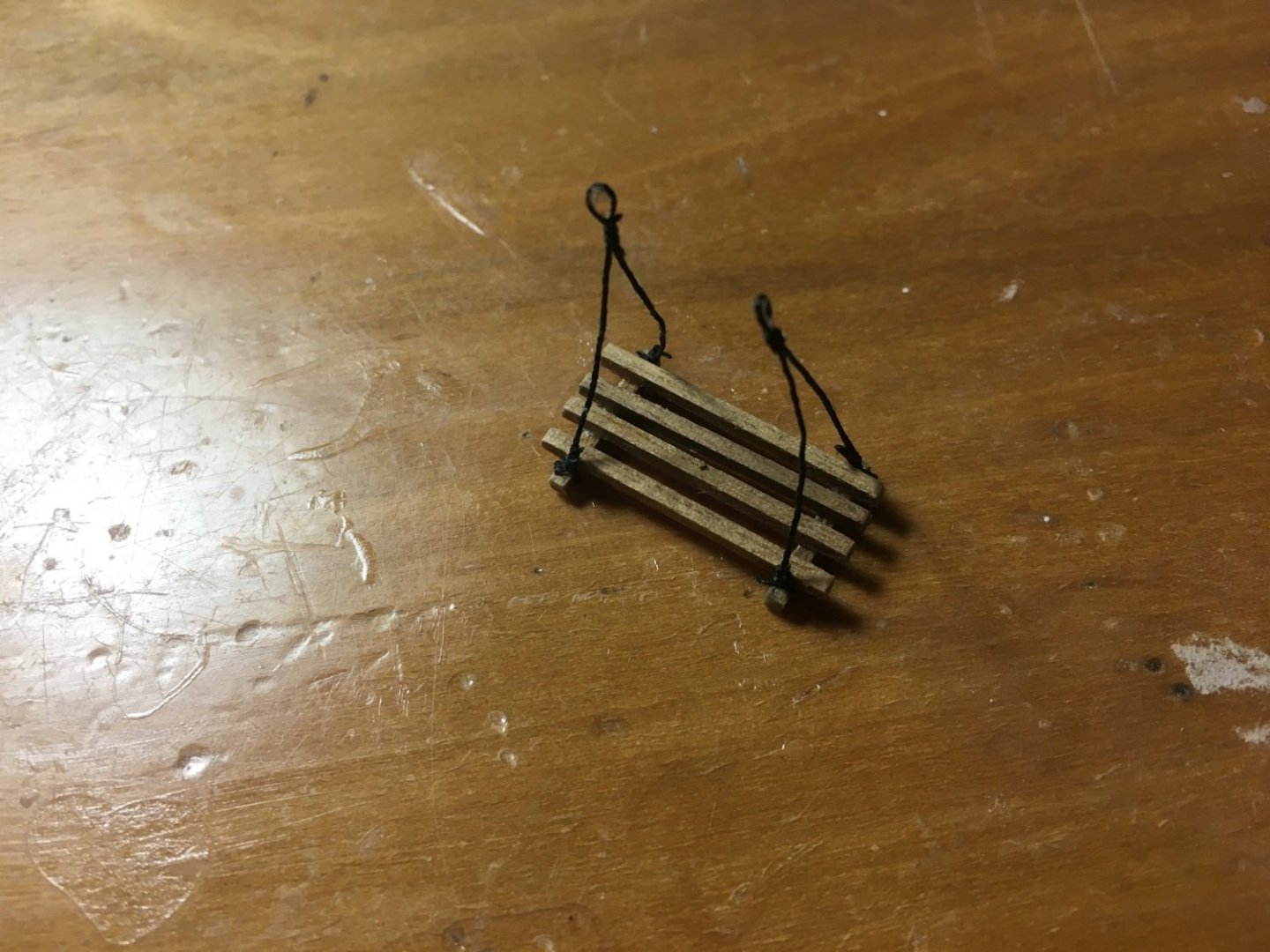
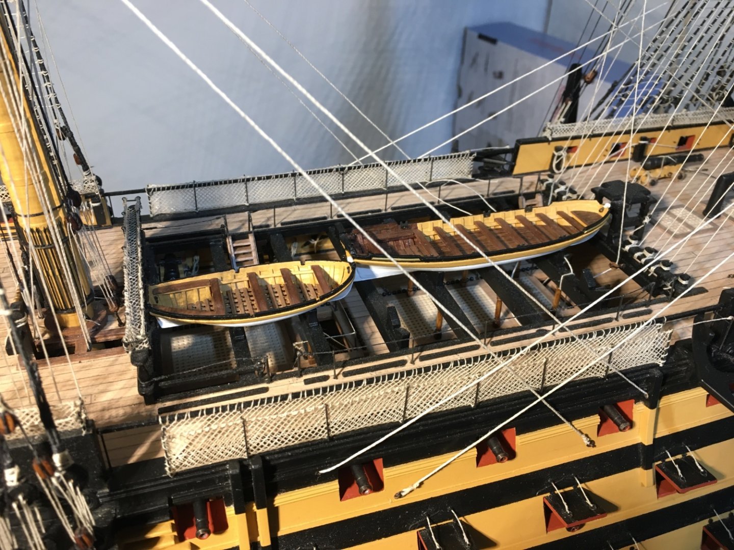
Ian, thank you again for your feedback. Even though I included the cathead stopper, I will leave the tackle as well. Sjor, thank you for your comment. I try my best as well. There are great and very skilful builders in this forum from whom I have learn a lot. Although I haven't completely rigged the anchors I continued some rigging on the davits. I had decided not to fit all four boats on deck, on the skid beams otherwise the only area that is still showing of the upper gun deck, will be obscured by the boats as well. Two of them I am hanging on the davits. The Launch and the Barge are the two boats going on the davits. I hooked them in place to find the right positions of the davit rigging and the of the tackles. I will unhook them again to add the fittings (oars, anchors, etc.) in them, which I have ready, just fit them in. The Launch on the starboard side. The Barge on the port side. The Pinnace and the Cutter to be rigged on the skid beams. I am not rigging them for now. I will leave them for the last minute as before I rig them in place I need to dust the deck under them. Fittings still to be adde in the boats as well. It's unbelievable the amount of dust the model accumulates. When finished I have to go over every inch of the model with a brush. Robert


- 521 replies
-
- 10
-
-
-
- caldercraft
- victory
- (and 1 more)
-
Thank you Ian for your reply and the images. That's what I think as well, that the large timberhead at the end of the bulkhead is the most obvious place to belay the cathead tackle. Sometimes soucing some detail is not so straight forward. Sometimes you can't find any and sometimes you find different and conflicting details. So sometimes you have to use your own judgment and go by that. But all in all the Internet is an incredible source of information. Robert
- 521 replies
-
- 1
-
-
- caldercraft
- victory
- (and 1 more)
-
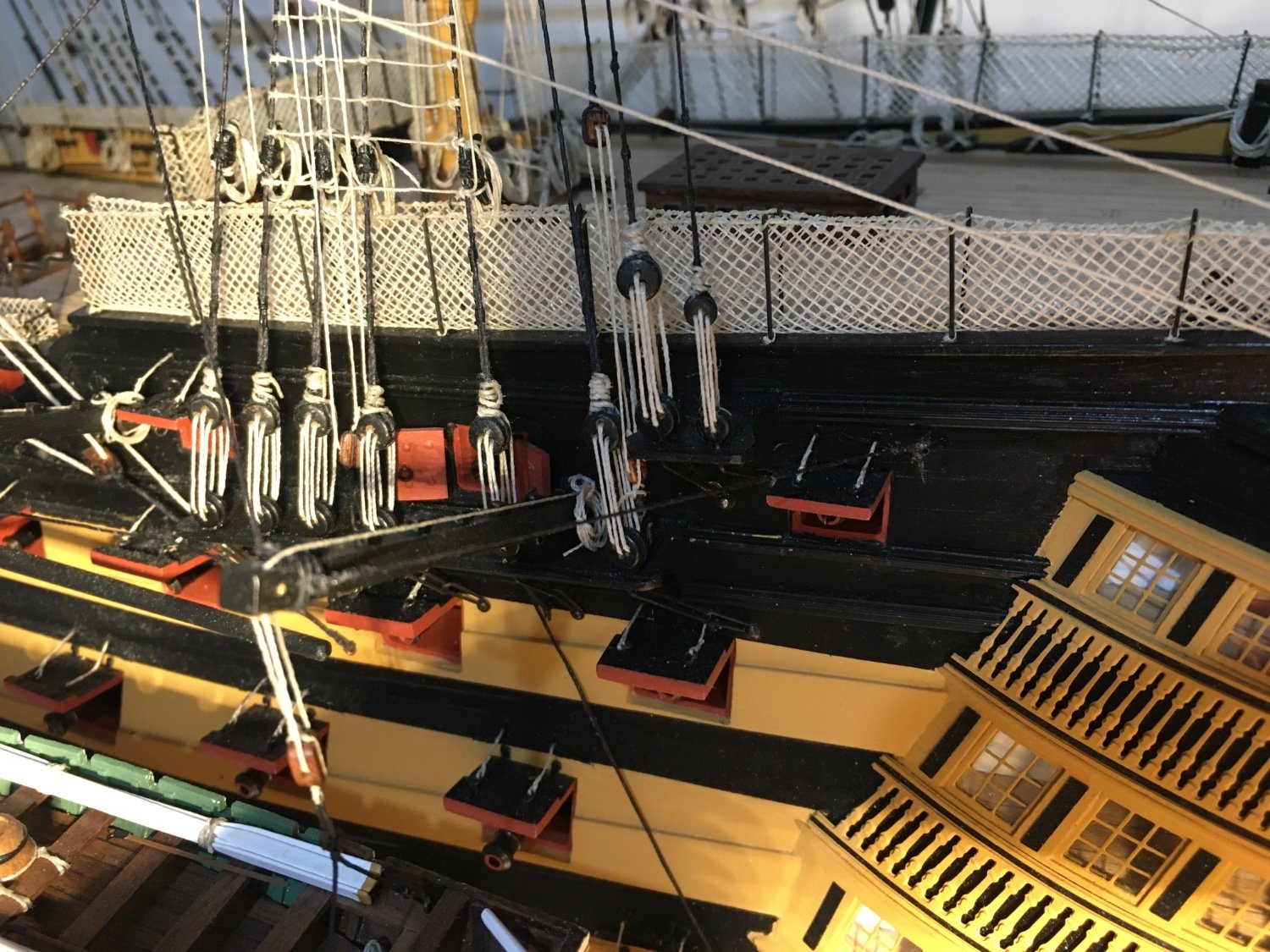
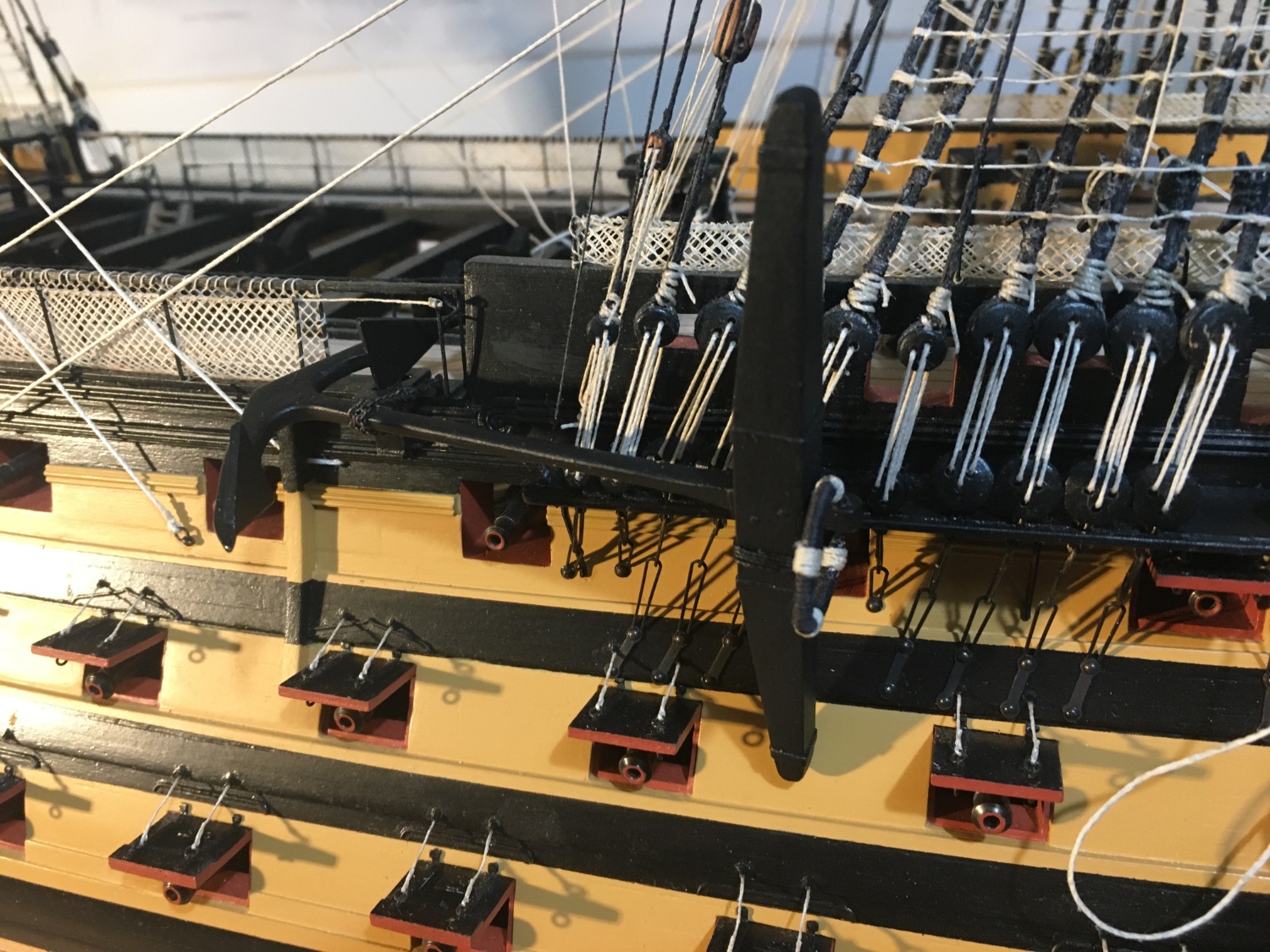
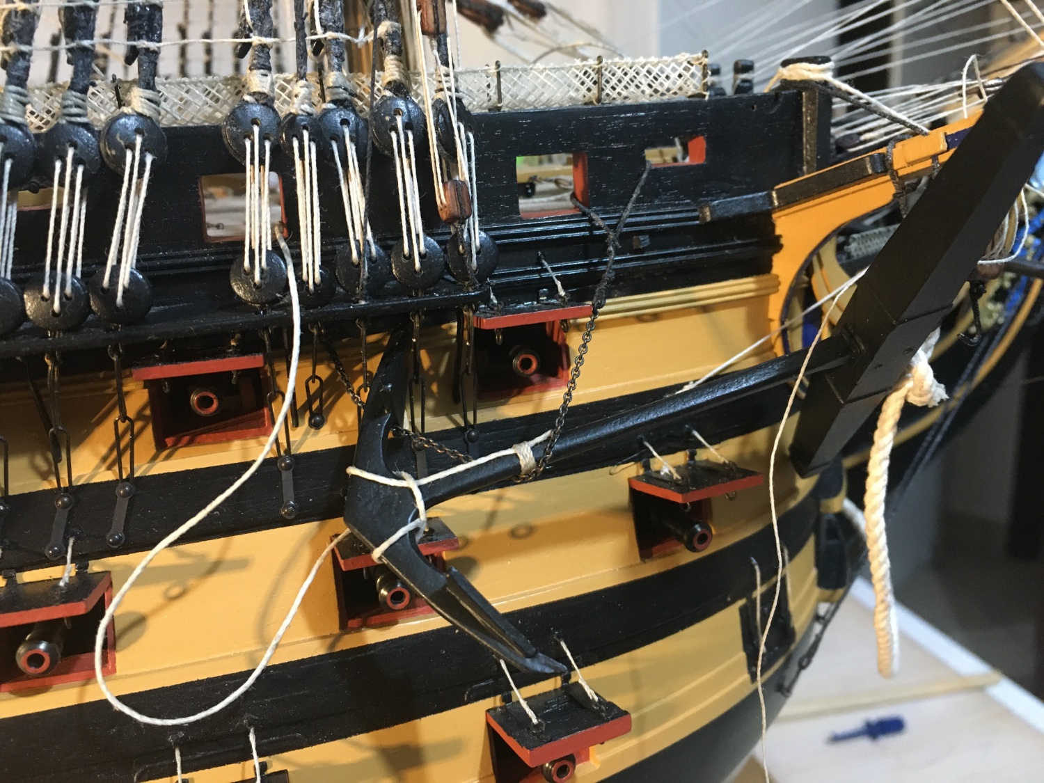
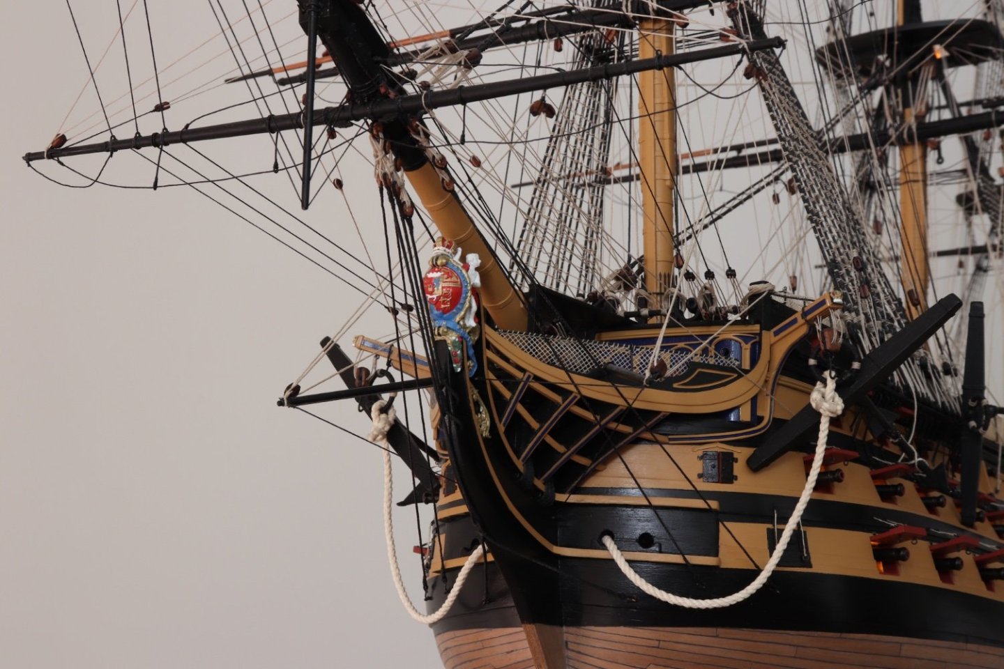
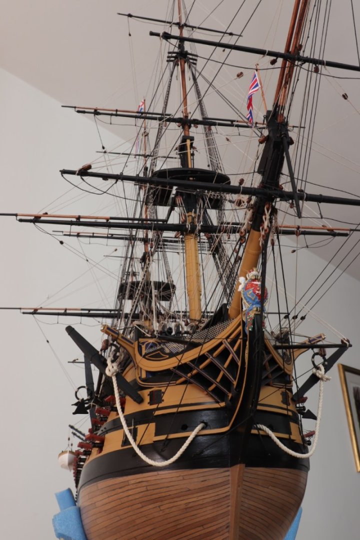
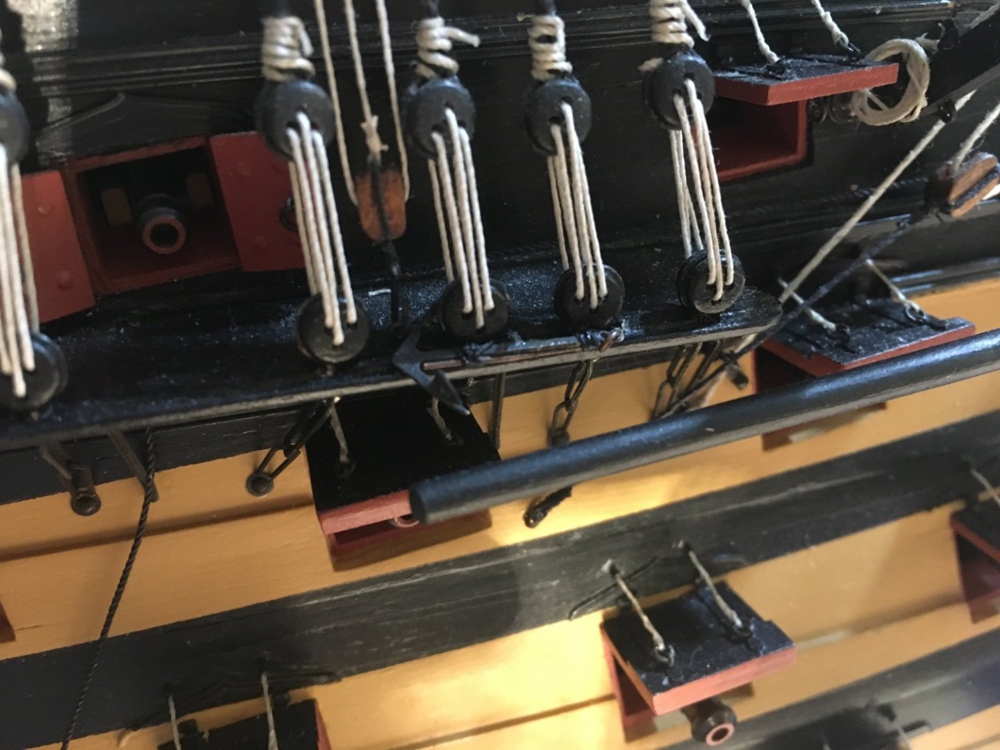
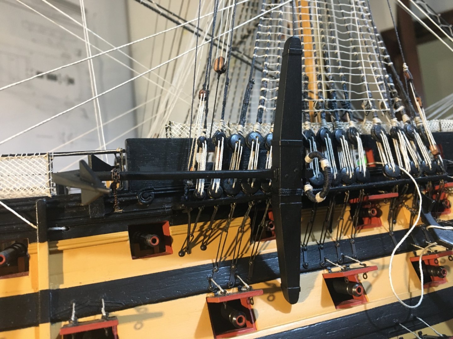
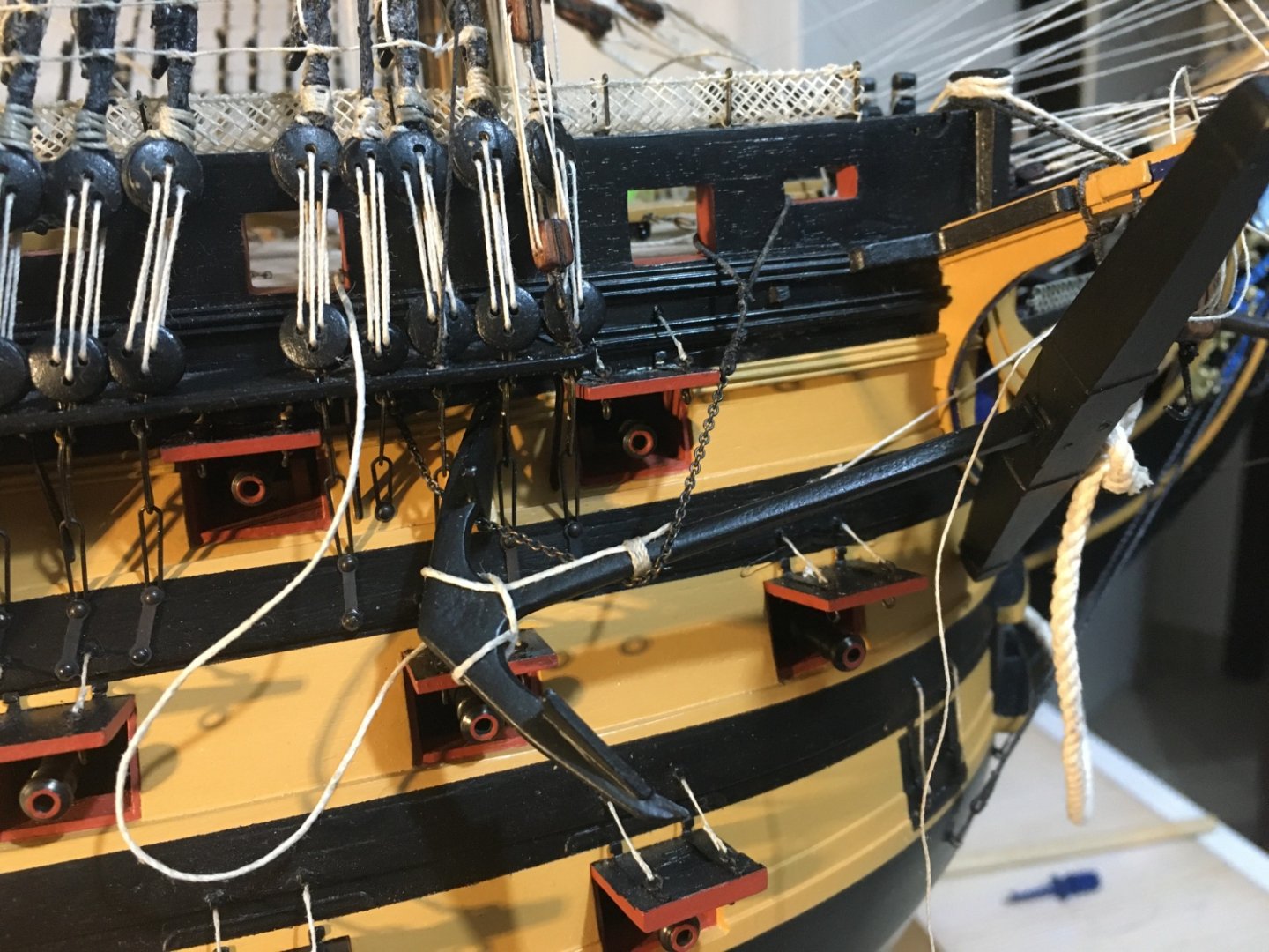
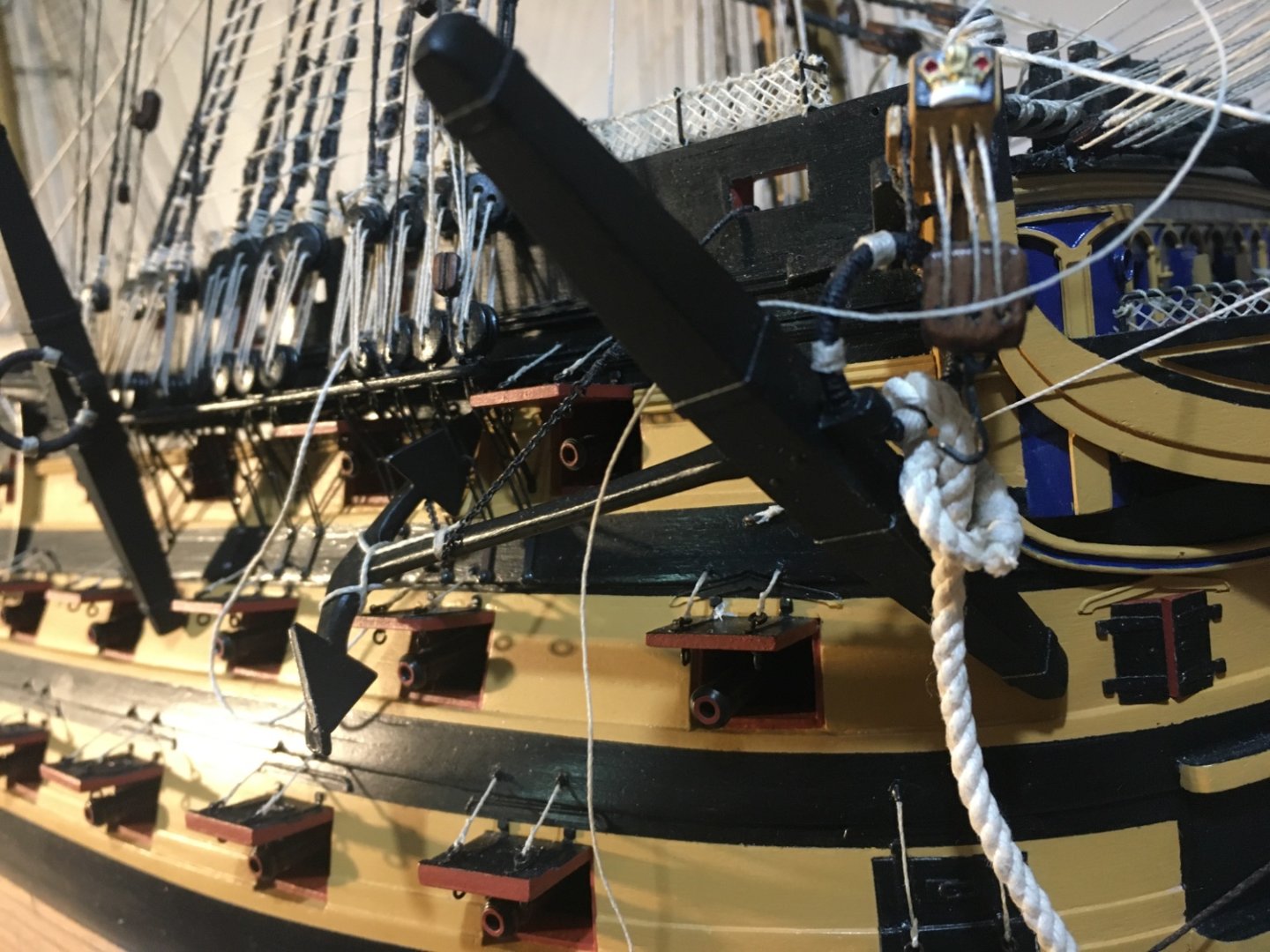
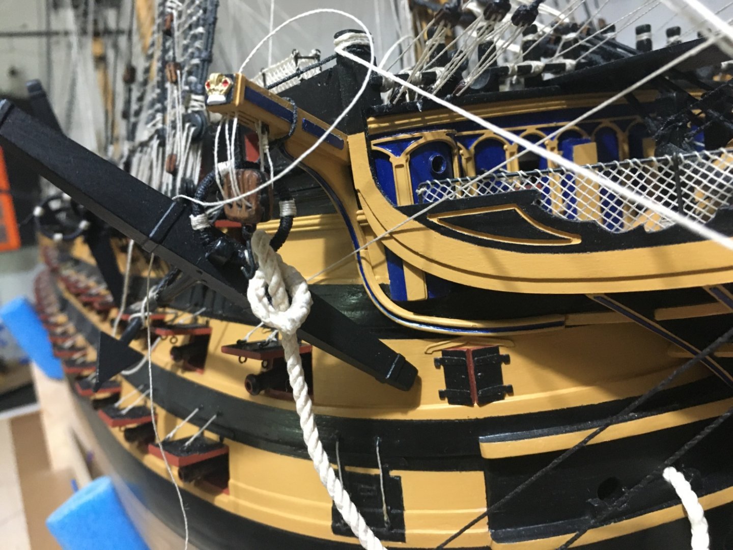
Thank you Graham. Hope it could be an idea to other builders. I found so many ideas in this forum from other builders in building my Victory. Anchors rigged in place as well. I deviated a bit from the manual's instructions on how the anchors are secured. I included some chain as seen in many of the pictures I sourced. Starboard Sheet Anchor. The Bower Starboard Anchor. Apart from the chain I also added the rope tied the the lower end of the anchor. Button I have no clue where the other end of this rope is belayed. The same with the running end of the cat head tackle line. The manual says it is to be belayed around the cathead at the cathead cleat. Shouldn't it be belayed somewhere on board behind the bulwark!!! Maybe I am wrong, I am no expert, any suggestions would be appreciated. Robert


- 521 replies
-
- 12
-
-
-
- caldercraft
- victory
- (and 1 more)
-
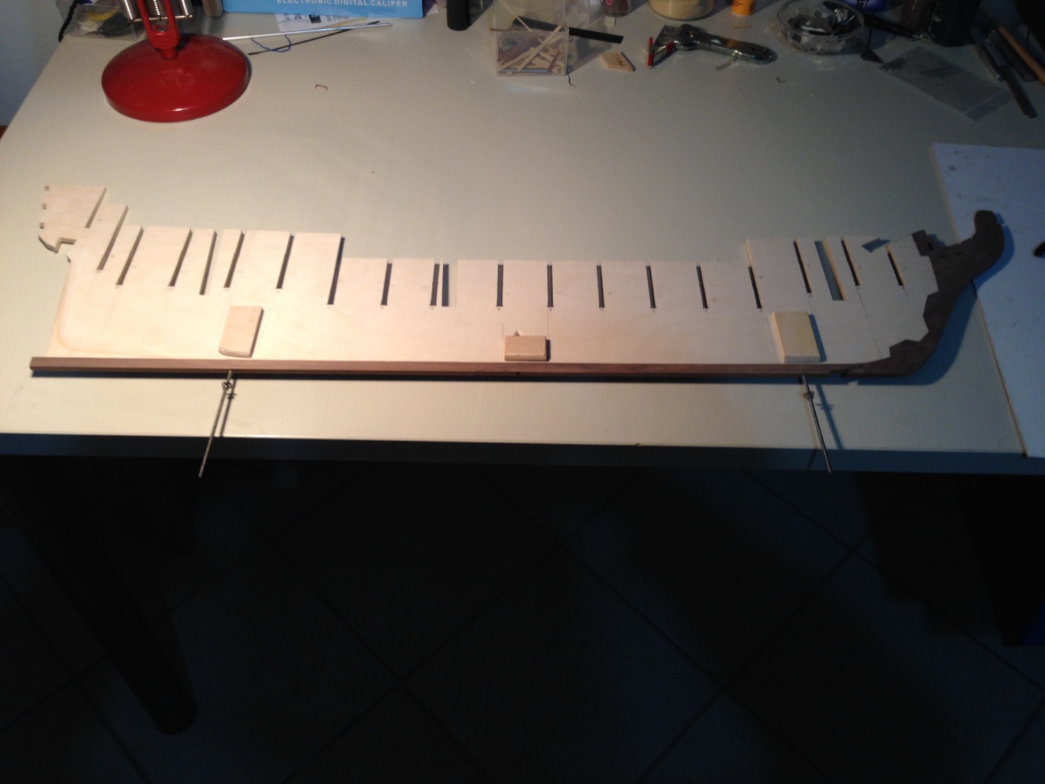
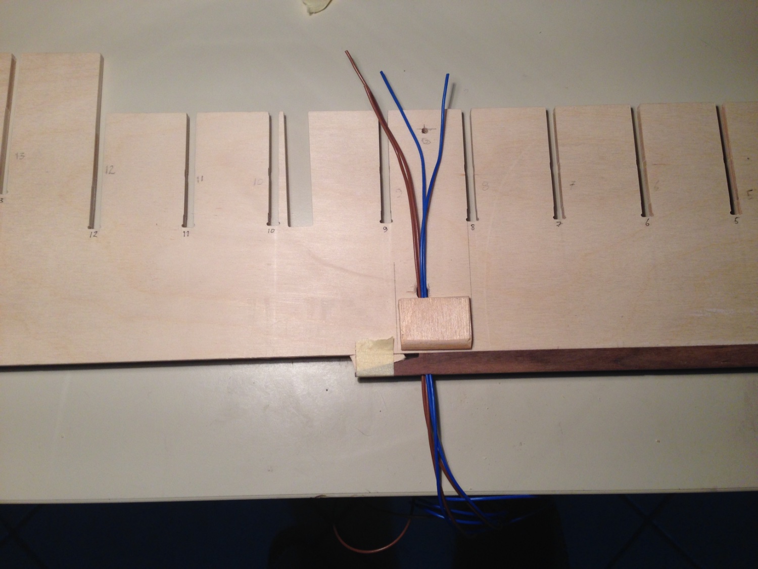
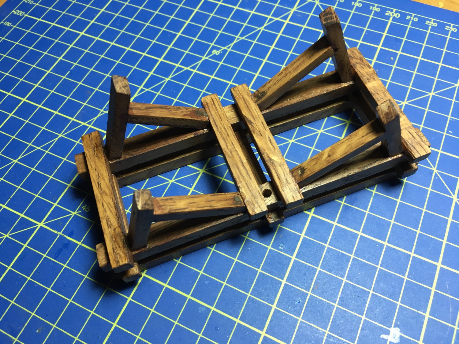
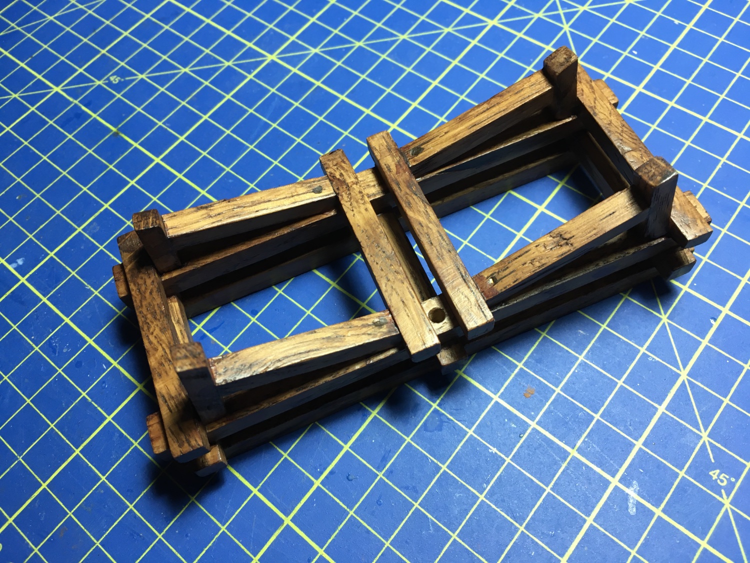
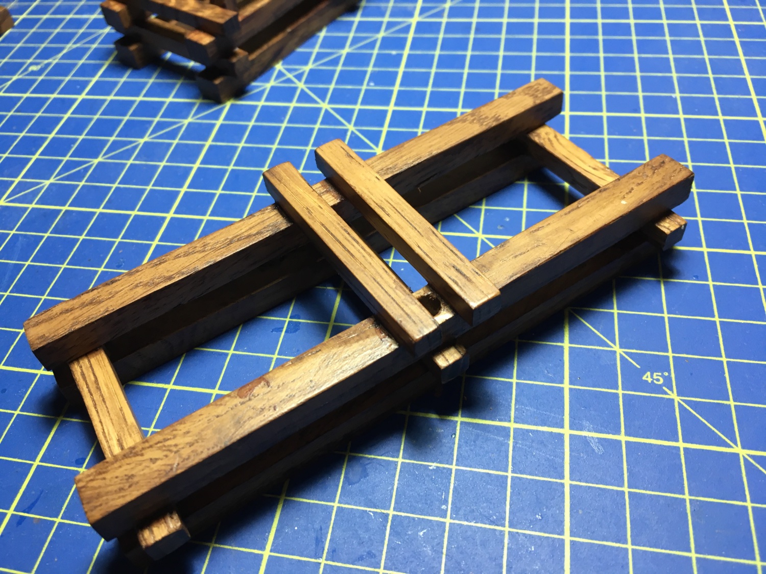
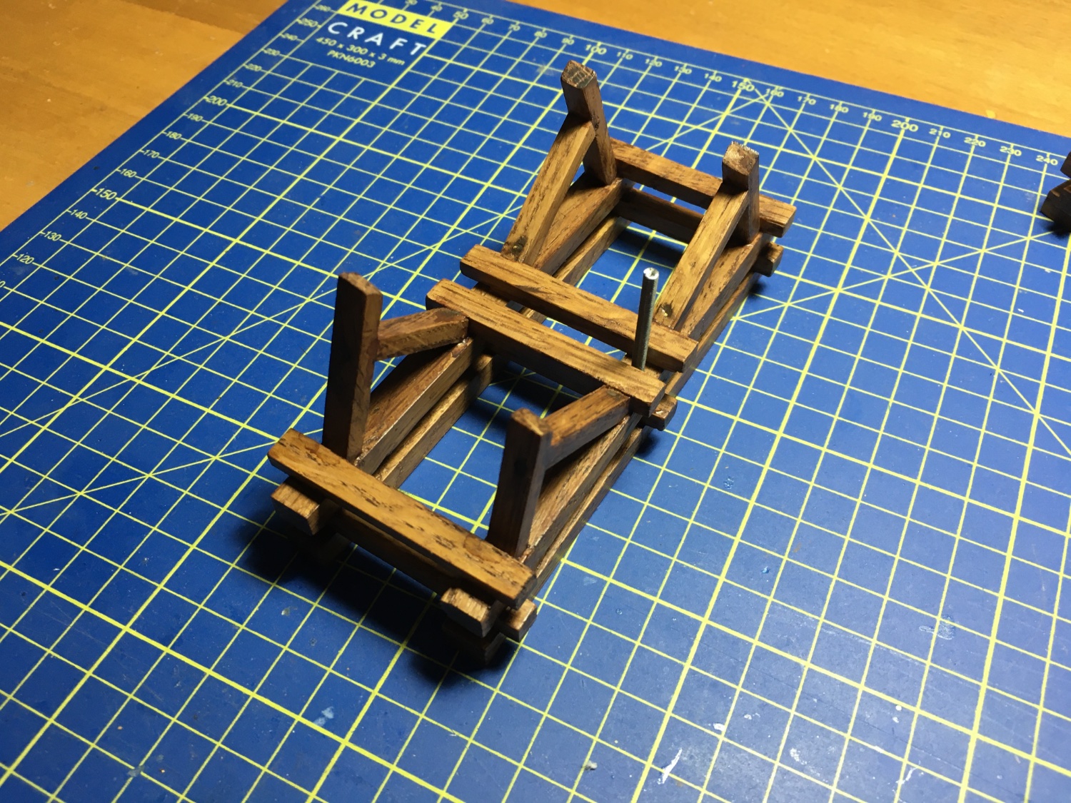
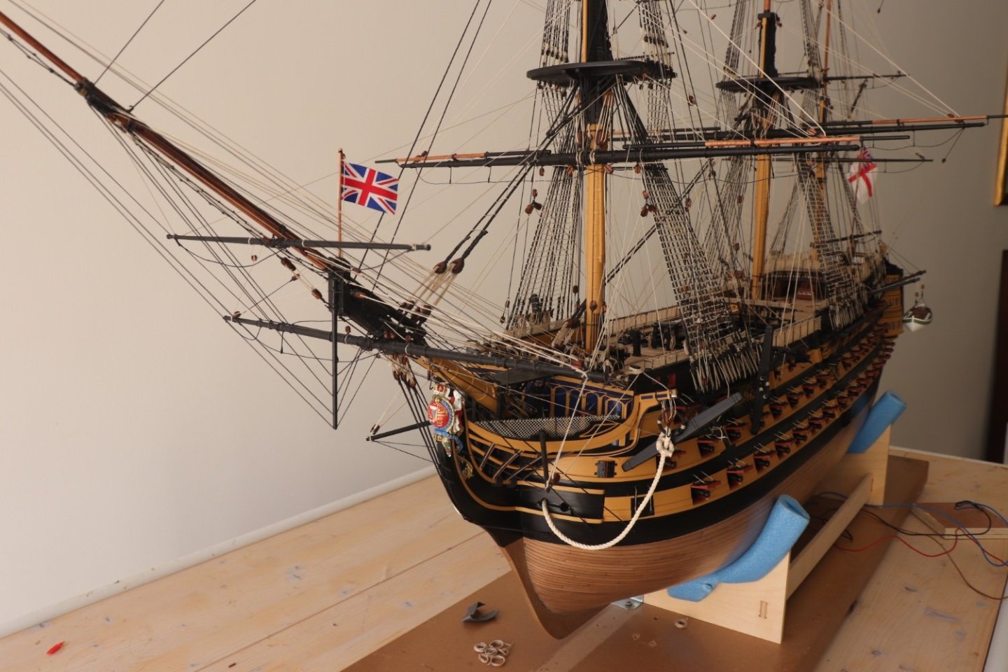
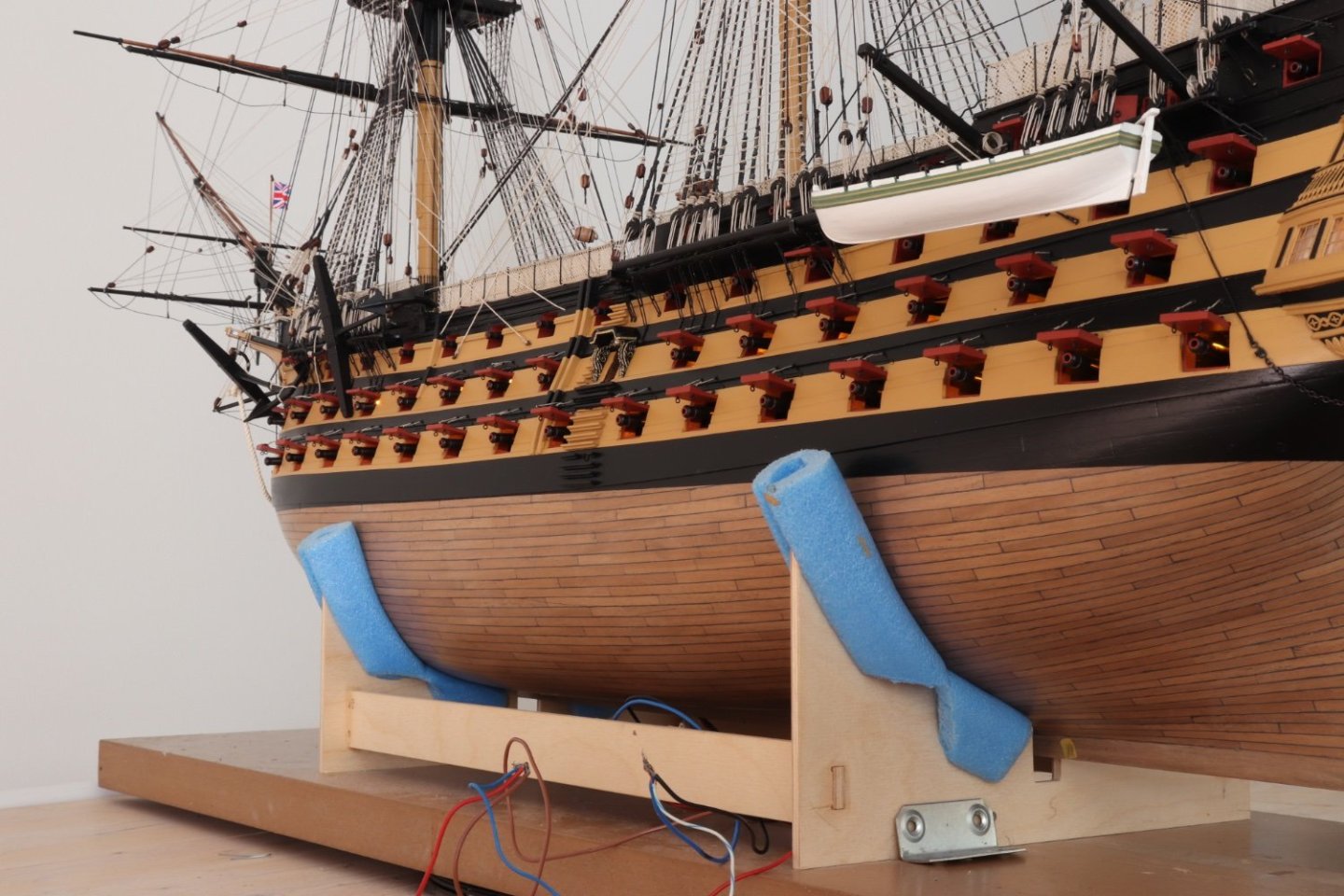
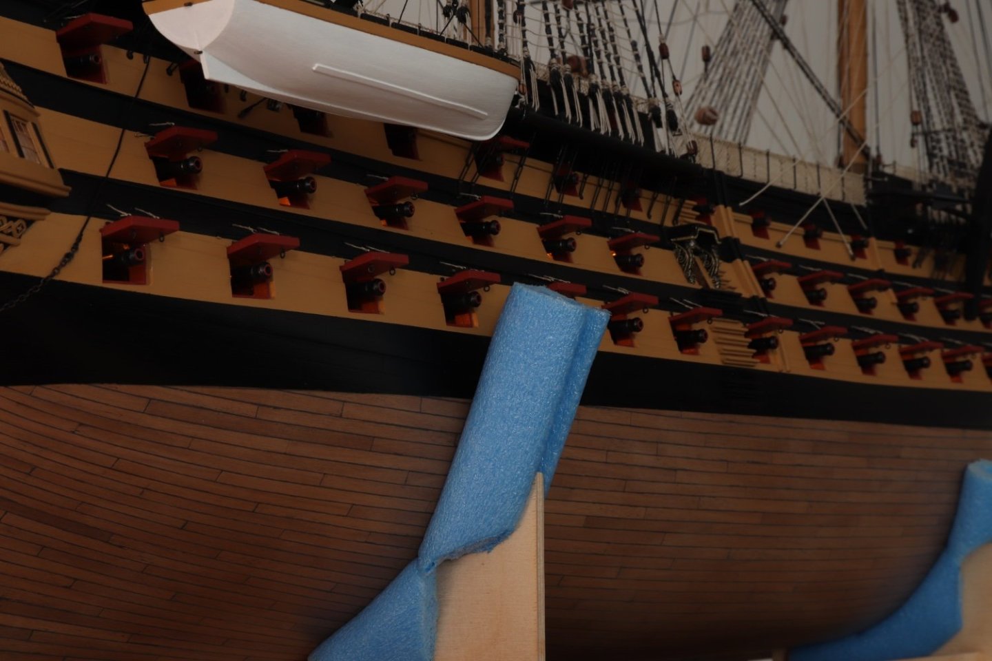
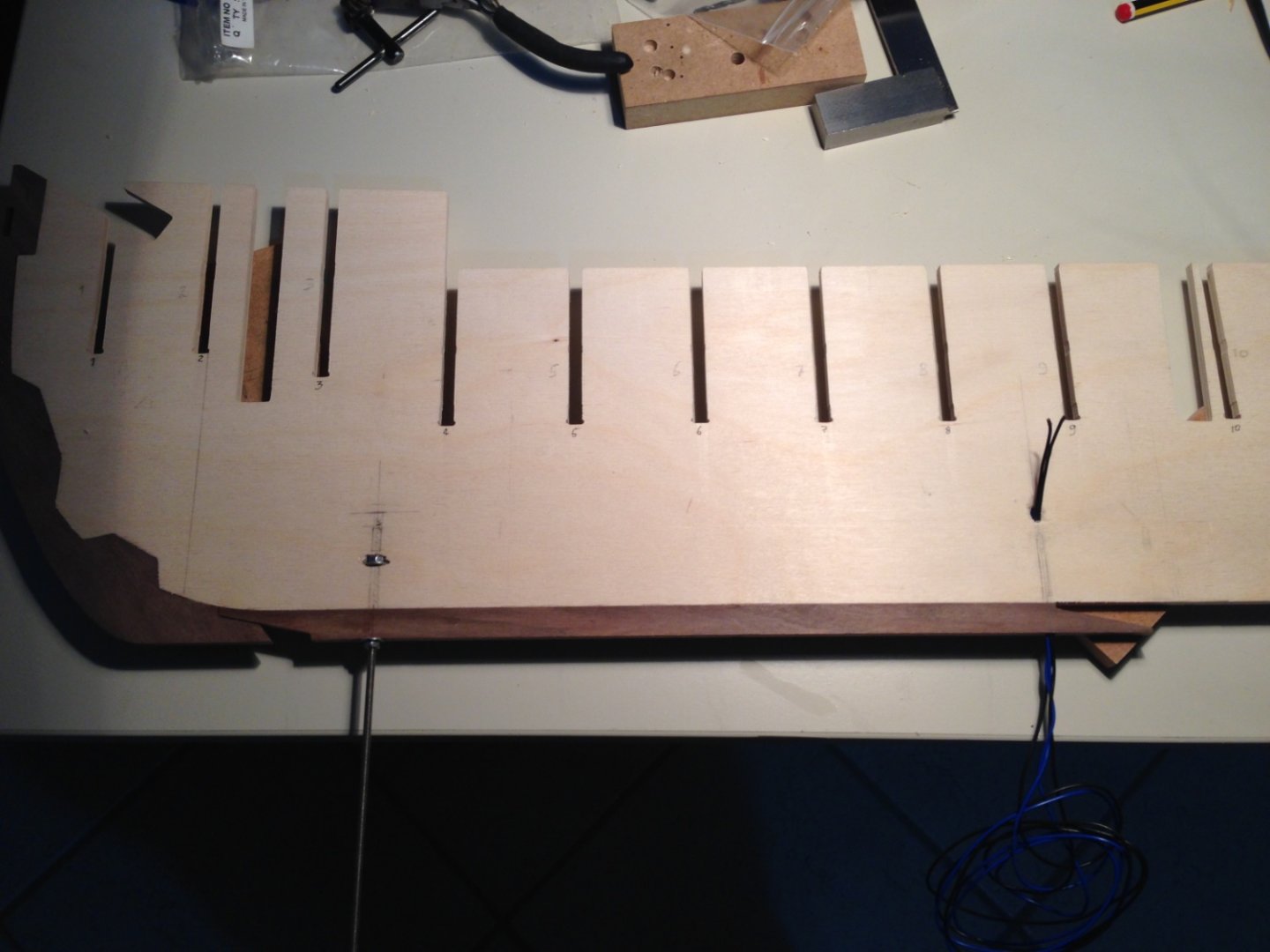
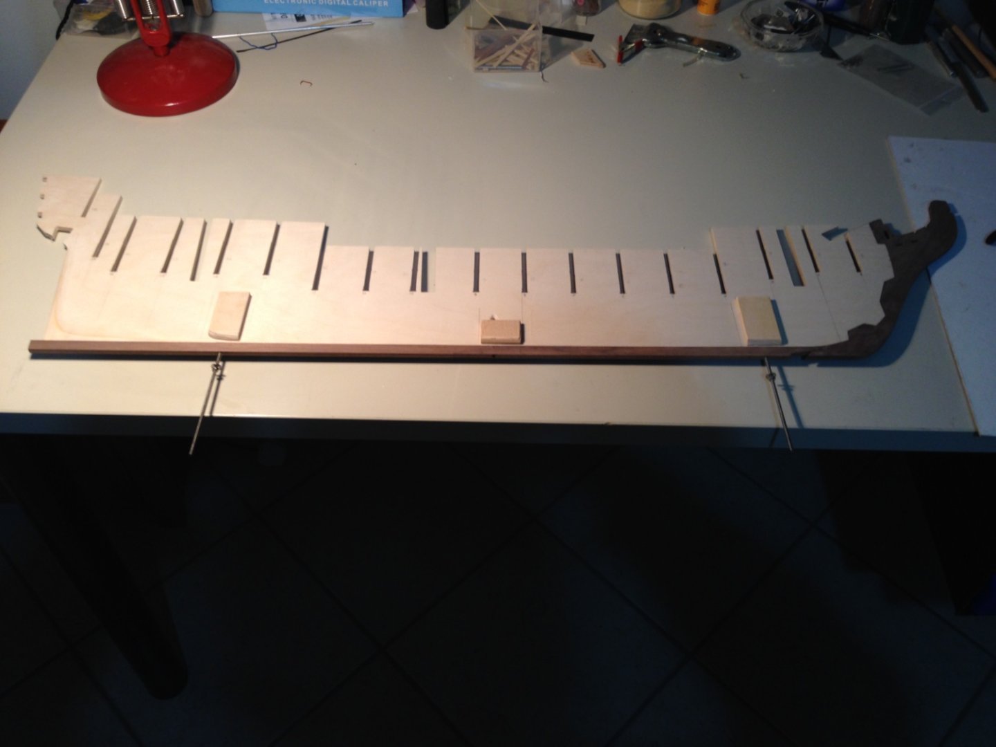
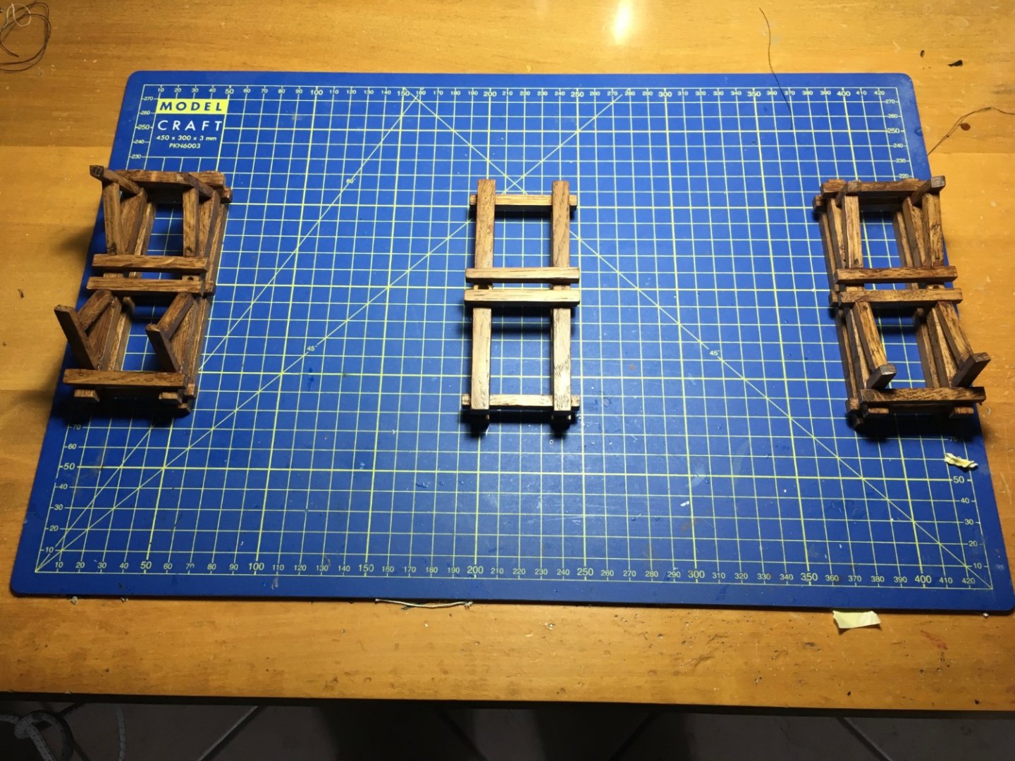
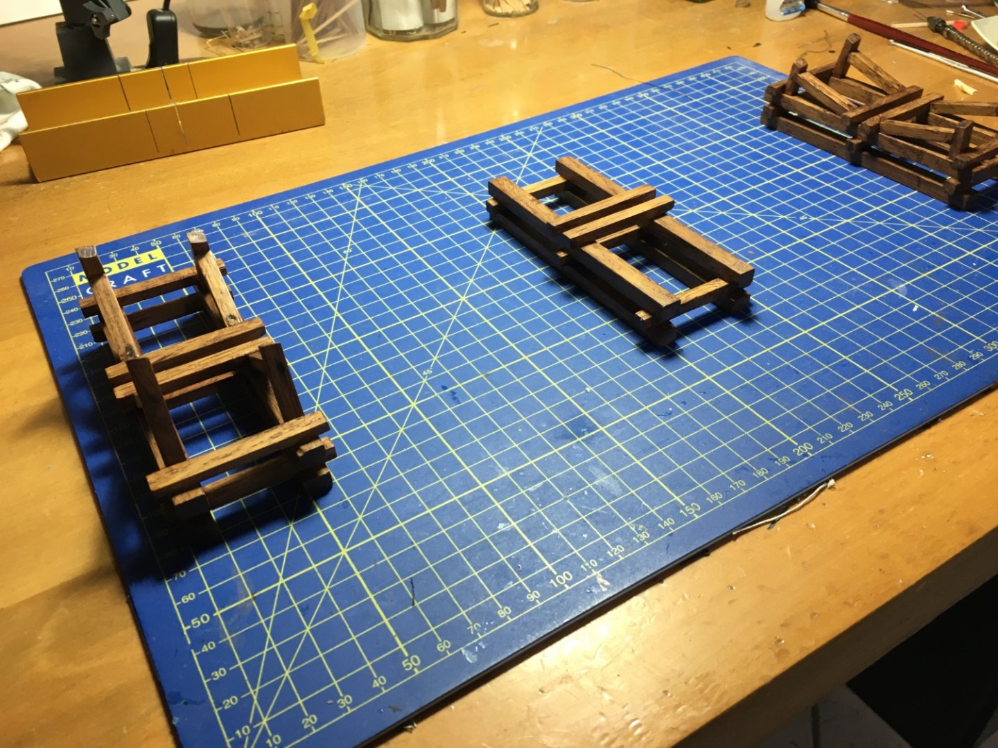
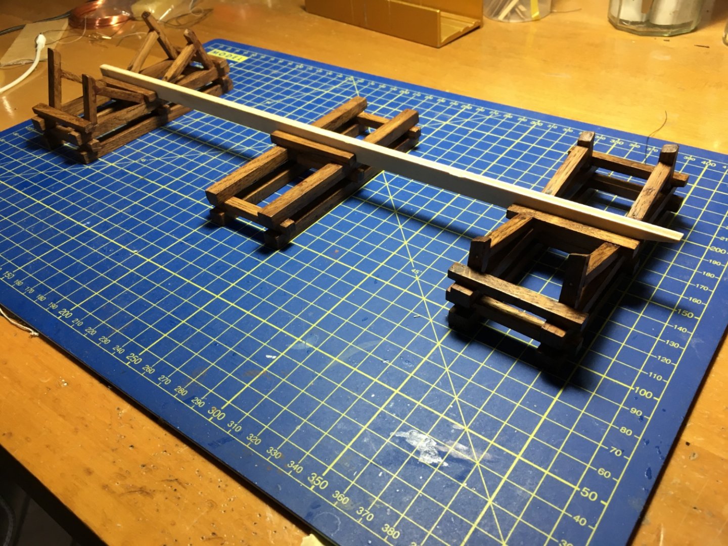
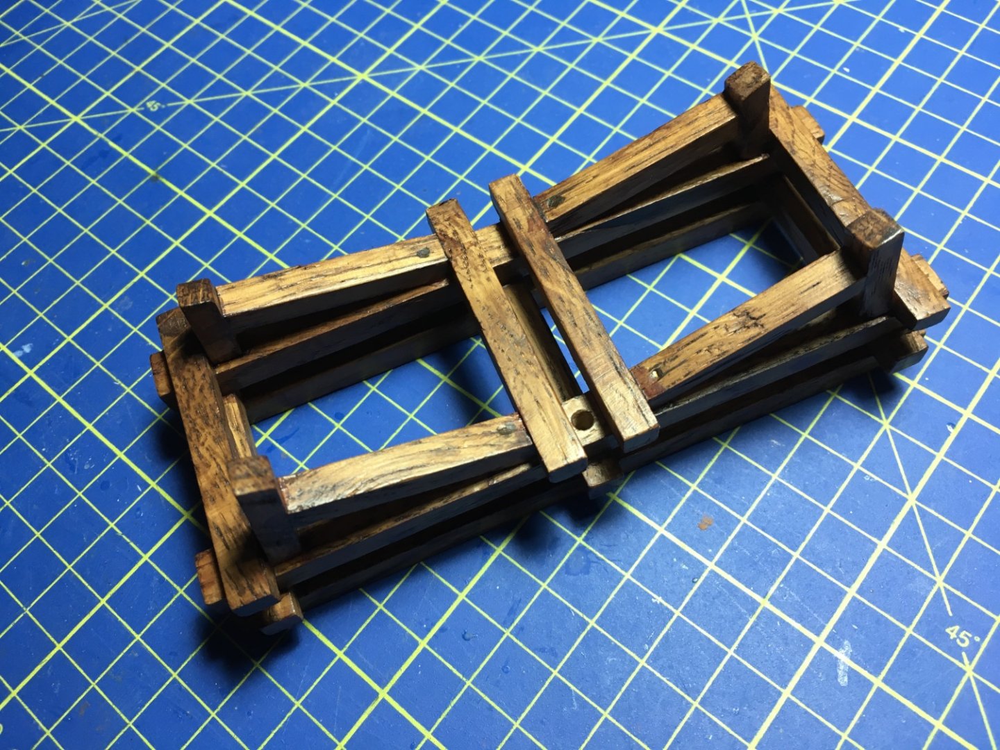
Thank you Captain Hook, yes it is a lot of work, and now that I am nearing the finish I am really eager to see how it looks when its in a showcase that I still have to make. It's been a long time with no updates. For the last month I had other priorities. End of November I went to visit my daughter and my grandson who live in Stratford-Upon-Avon in the UK. Christmas time they came to Malta and were staying with me, so basically I did not have much time for the Victory. At the moment I am fitting the anchors, for which I will soon have some photos to upload. For quite some time I have been thinking what am I going to rest the Victory on when its in the showcase. I did no want to make any curly fancy stands and I came up with the following idea. I had some wooden strips which were left over trimmings from another house project and decided to use them. In the very beginning of the project, in the kit manual it was advised to drill holes though the keel and embed a nut inside to take a threaded rod which then can pass through whatever stand is used and again through a base/table top and secured with another nut on that end. Apart from the holes for the threaded rods I also drilled another hole for the supply wires for the led lights I installed. The keel will rest on the stands in between the wooden bars to hold it in place. The supports on the sides are made to the exact measurements to support the hull and keep the ship from leaning to any side. This is the stand on the stern side. A hole is drilled on one side through which the threaded rod coming out of the keel will pass through and secured to the base. This way the threaded rod will be completely hidden. Same thing with the stand on the bow side. This is the stand in the middle. I did not really need this stand, but I needed something to hide the supply wires coming out of the keel which are to be connected to a transformer hidden under the display table. I drilled a hole on one side through which the wires will pass through. There are no visible wires feeding the led lights throughout the ship, not even the supply wires now. Hoping to be back soon with photos showing the anchors, Robert


- 521 replies
-
- 8
-
-

-
- caldercraft
- victory
- (and 1 more)
-
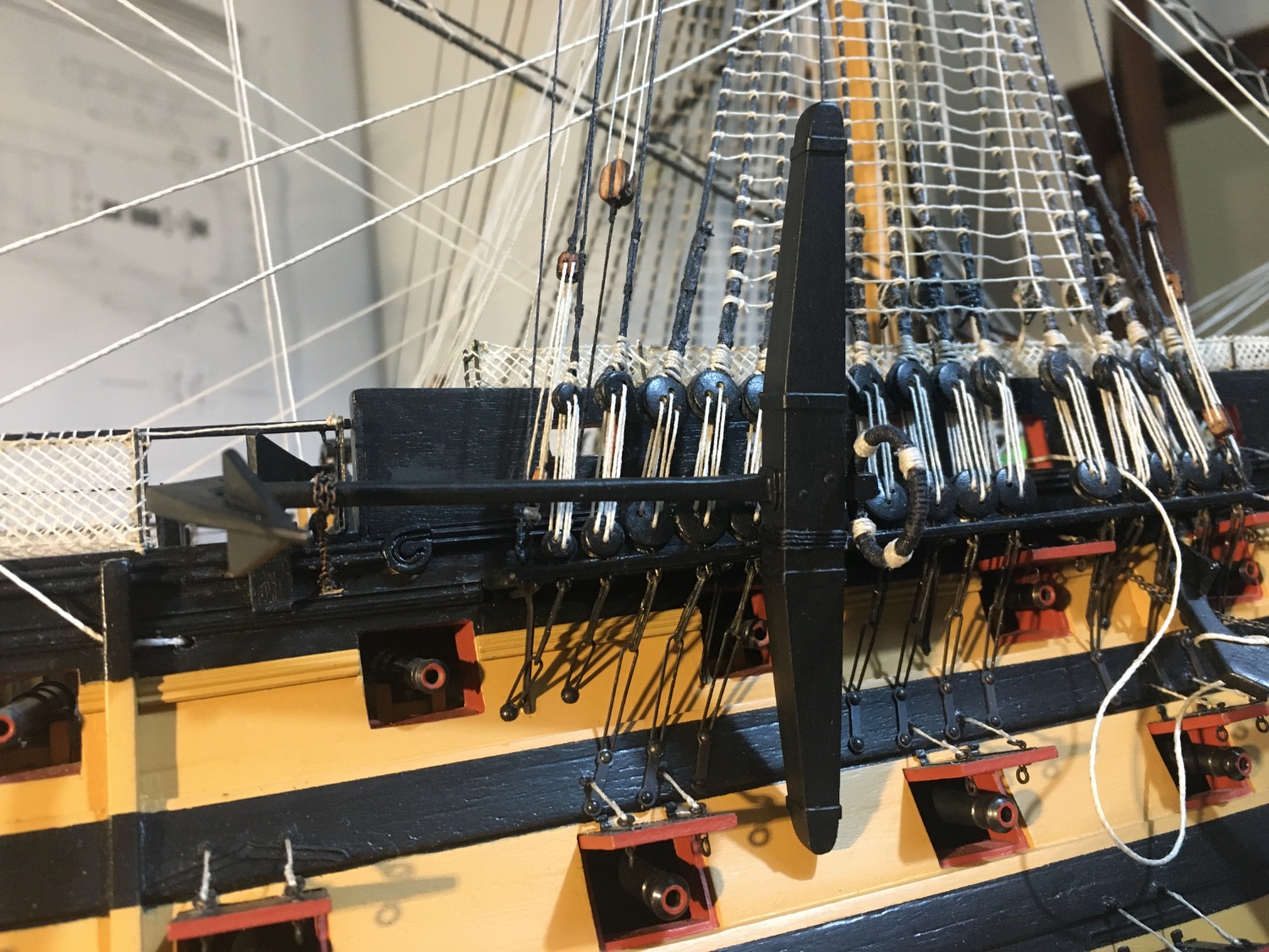
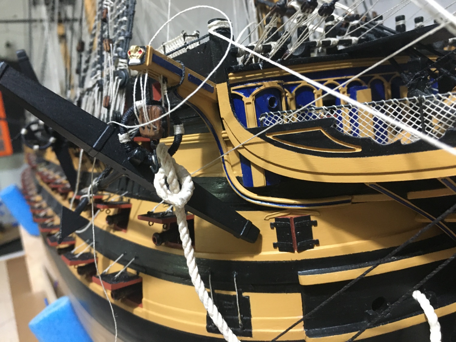
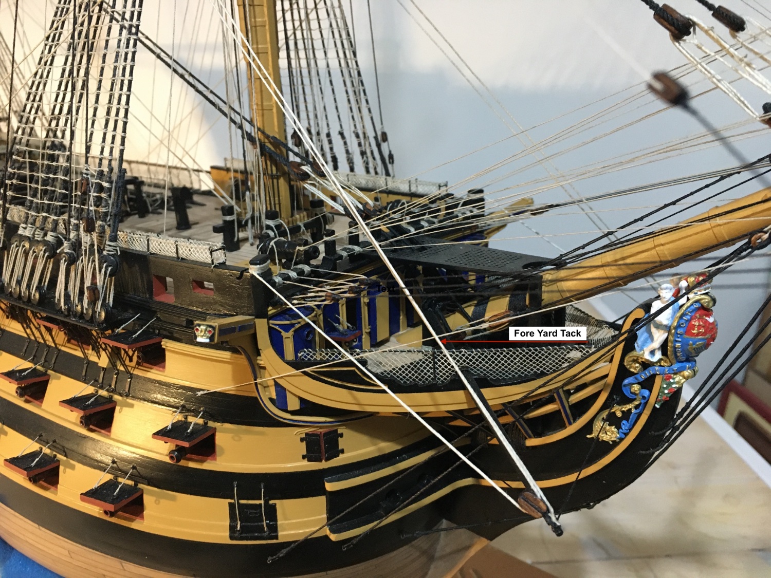
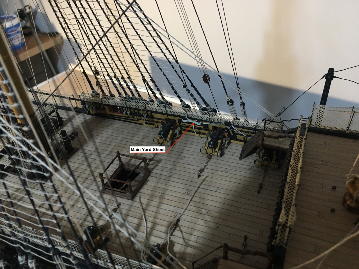
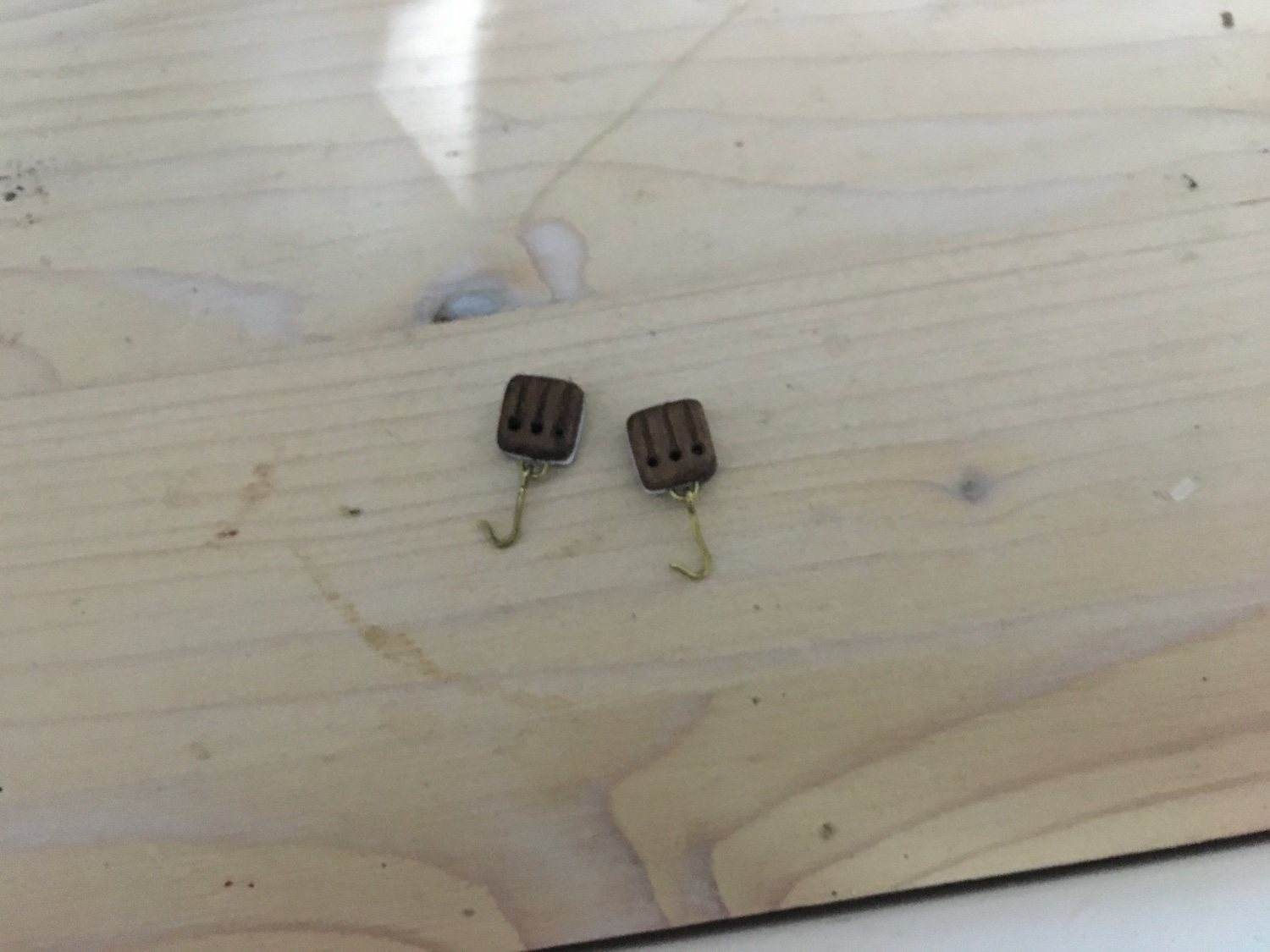
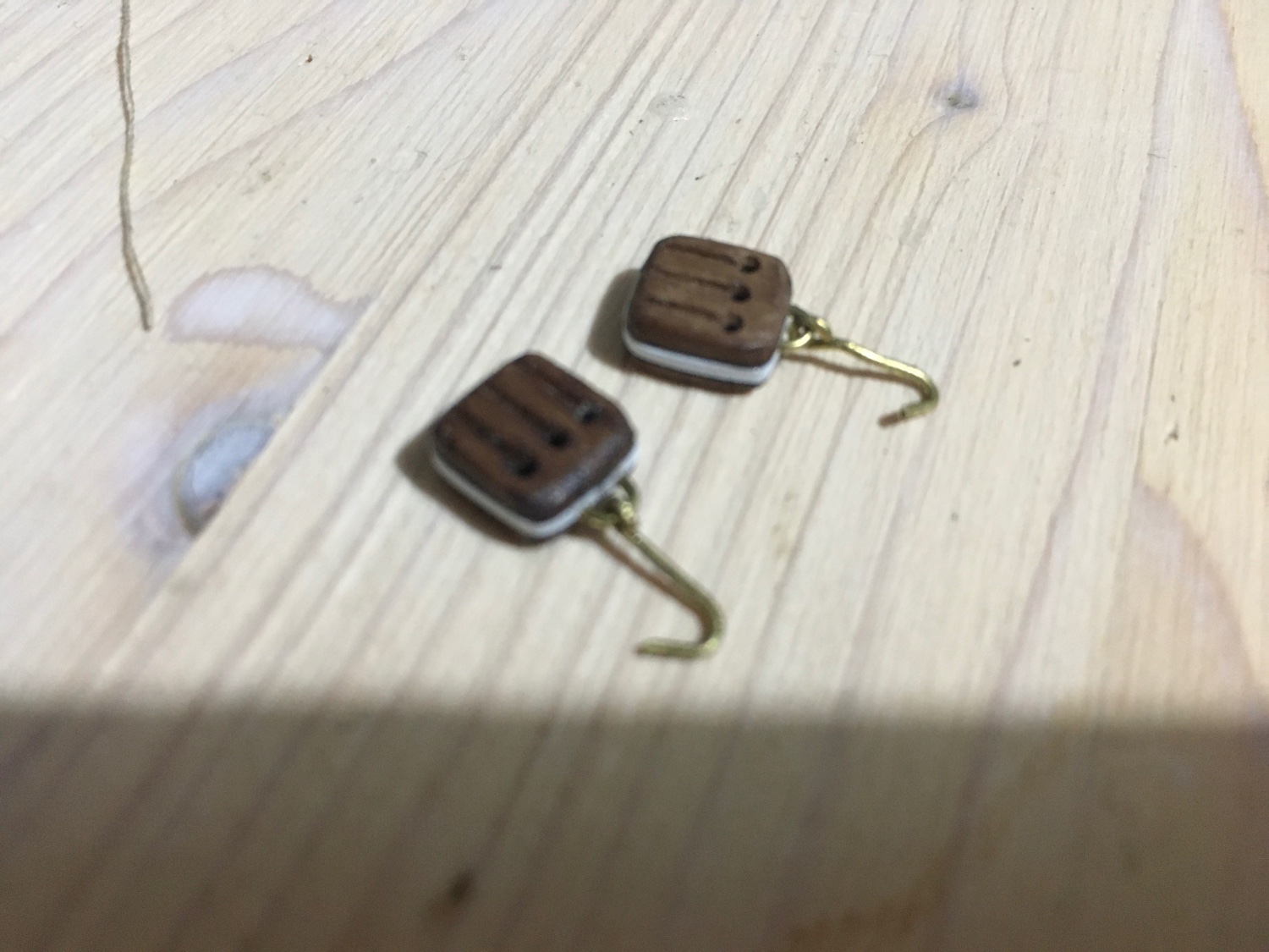
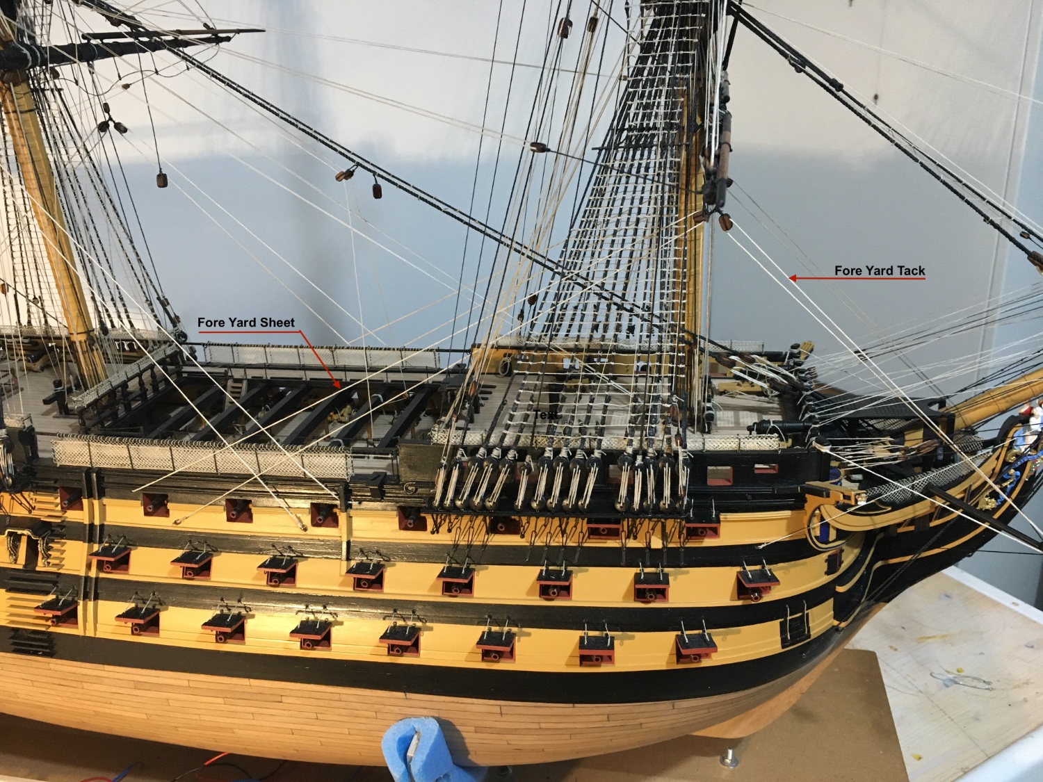
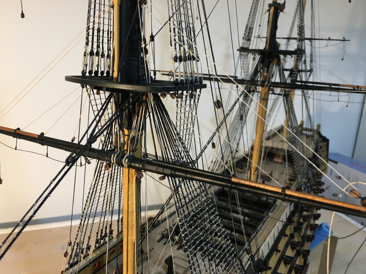
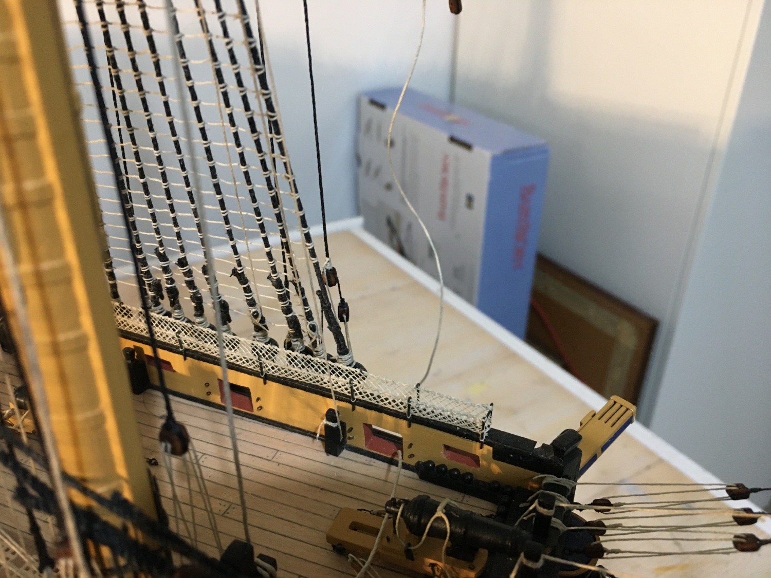
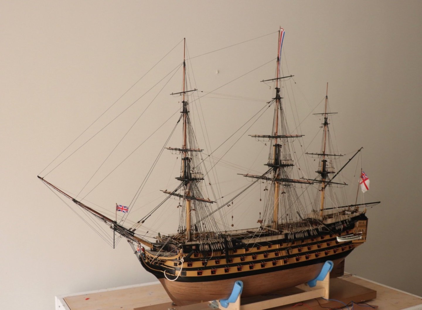
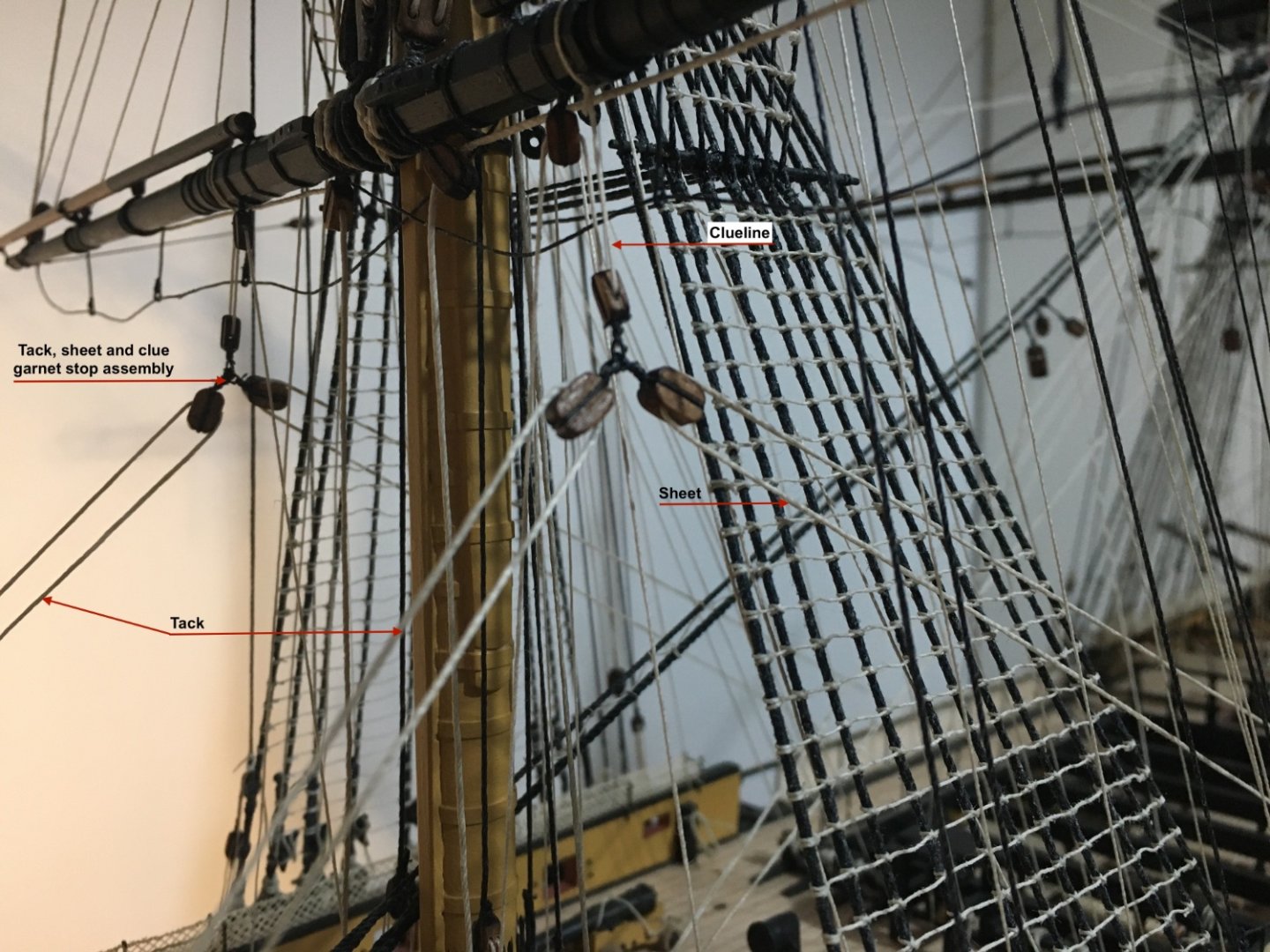
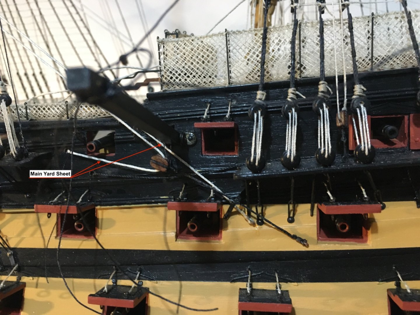
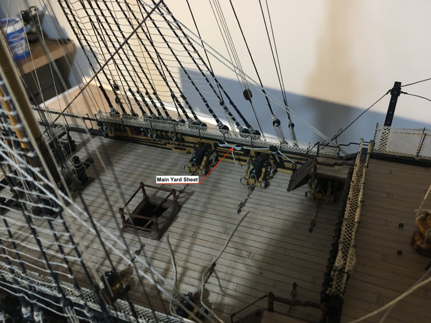
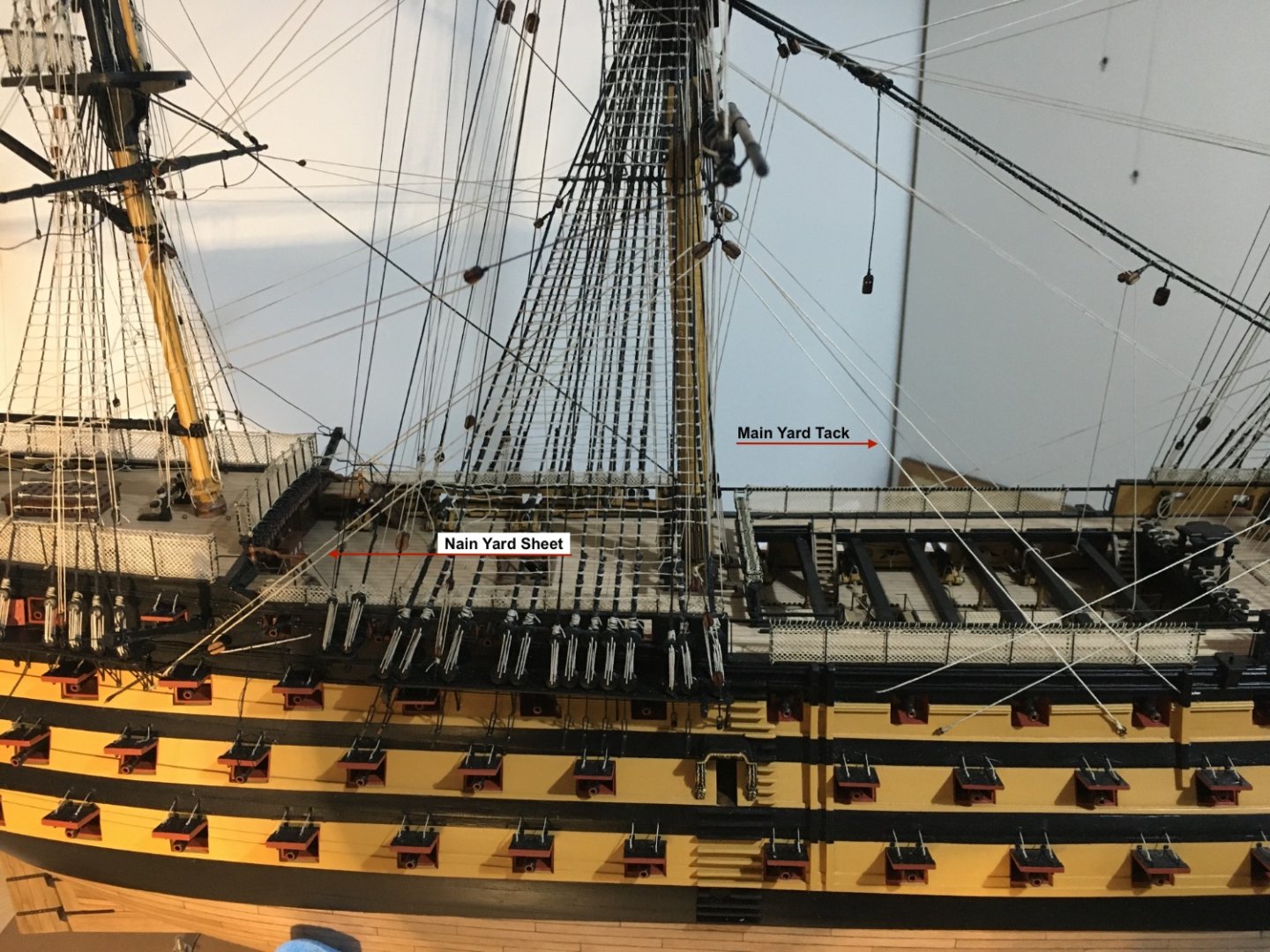
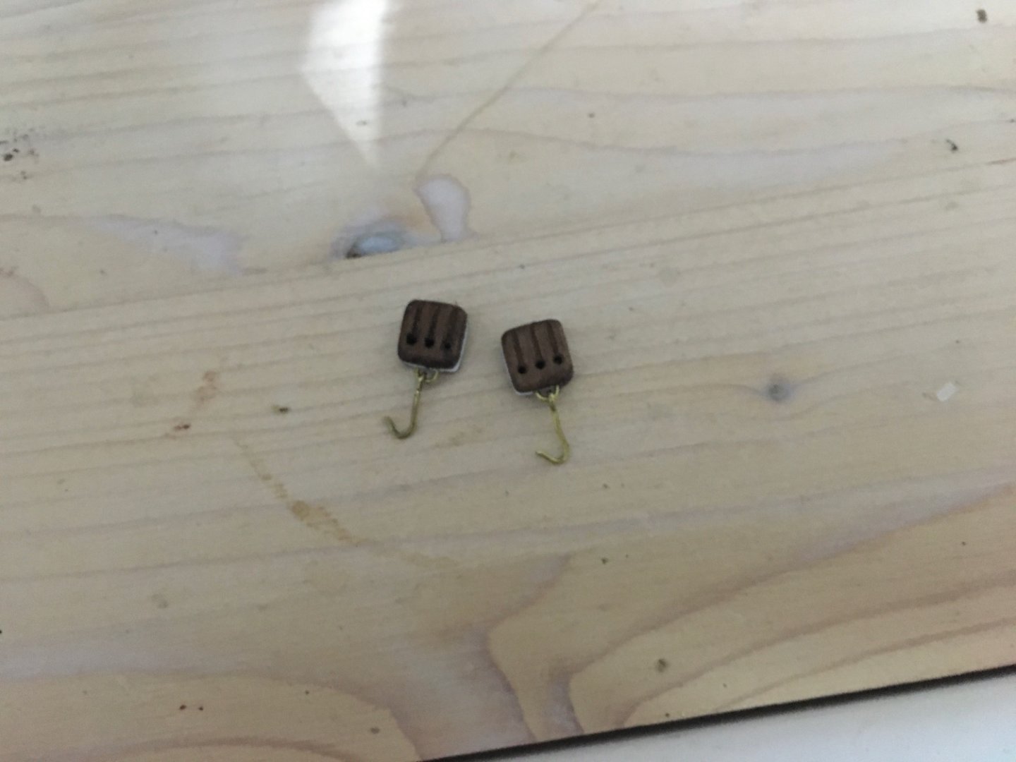
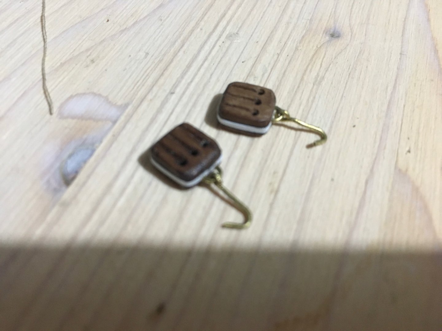
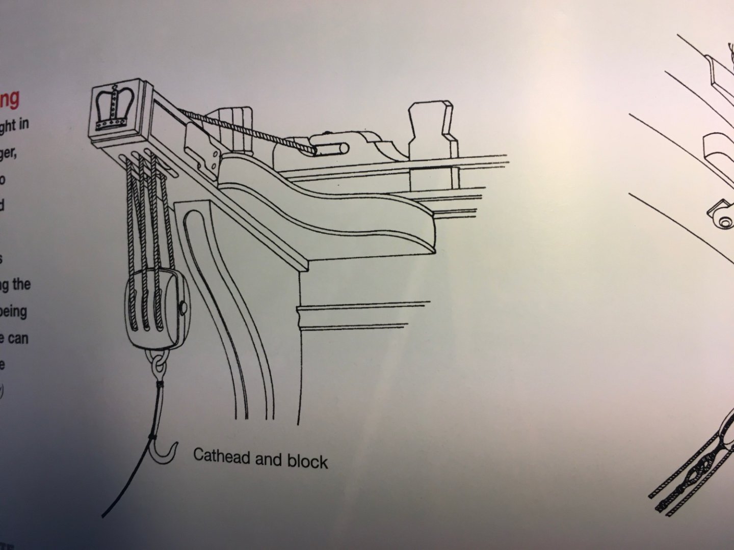
Thank you for the Likes. Fore and Main Mast Yard clue lines, sheets and tacks rigged in. Tack, Sheet and Clue garnet strop assembly. Fore Yard Tack made fast to the end of the boomkin, up to the 7mm single tack block on the strop assembly, down through another 7mm single block seized to the boomkin and belays to the top of the headrail. The Yard Sheet standing end is made fast to an eyelet on the hull up to the 7mm single block, back to the hull and passes through the ships side to the upper gun deck where it belays to a large cleat. Main Yard Tack is tied to an eye on the hull up to the single block, down to the side of the hull again, first passing through a hole on the side of the chesstree then through a sheave hole on the side of the hull to the upper gundeck where it is belayed to a large cleat. The Main Yard Sheet is tied to an eyelet below the spider, up to the 7mm single block, down again through another single block held in a pendant (standing end of pendant is tied to an eyelet behind the spider and passes through the ring of the spider) then up again and passes through a sheave hole in the hull to the quarter deck and belayed to the staghorn. Main Yard Sheet coming in through the sheave hole just behind the poop deck stairs and belayed to the staghorn. Now it is also time to start adjusting the yard horses and giving them that sagging look. I am using small clips to weigh down the line, brush over the line with PVA glue, heavily diluted with water, let it dry and remove clips. The clips jaws are not clamped on the horse line, otherwise it will distort the line. There is an open space just behind the jaws. Result is quite satisfactory. If you look at the Fore Yard horses which are already done, and at the Main Yard horses, not yet done, you can see the difference. An overall image how she looks at the moment. Also started looking how to hang the anchors to the sides of the hull and the cathead falls. The first thing I noticed was that erroneously, when forming the the triple blocks I formed a groove around them to take the rope. They are not seized to any rope. After sourcing some information on the internet I found that the end of the falls is tied to an eye on the underside of the cathead, and a tackle is formed between the cathead and the block. The block itself has an iron bar going around it with an eye formed at the bottom and a hook attached to it. To simulate the iron band I glued a strip of styrene around the block, at the same time covering the groove I had previously made. Formed a hook and a U shape with a piece of a brass rod and glued the U shaped rod in two holes drilled on the underside of the block. Band, hook and eye will be painted black. Robert


- 521 replies
-
- 11
-
-
- caldercraft
- victory
- (and 1 more)
-
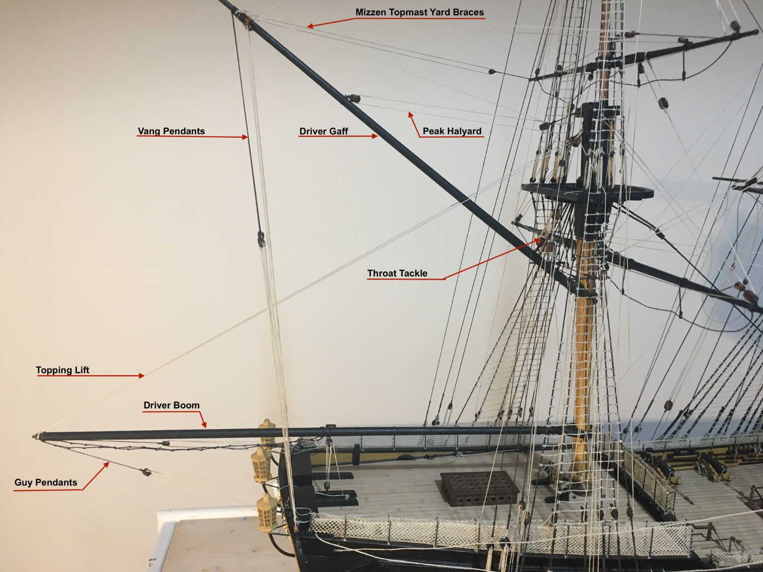
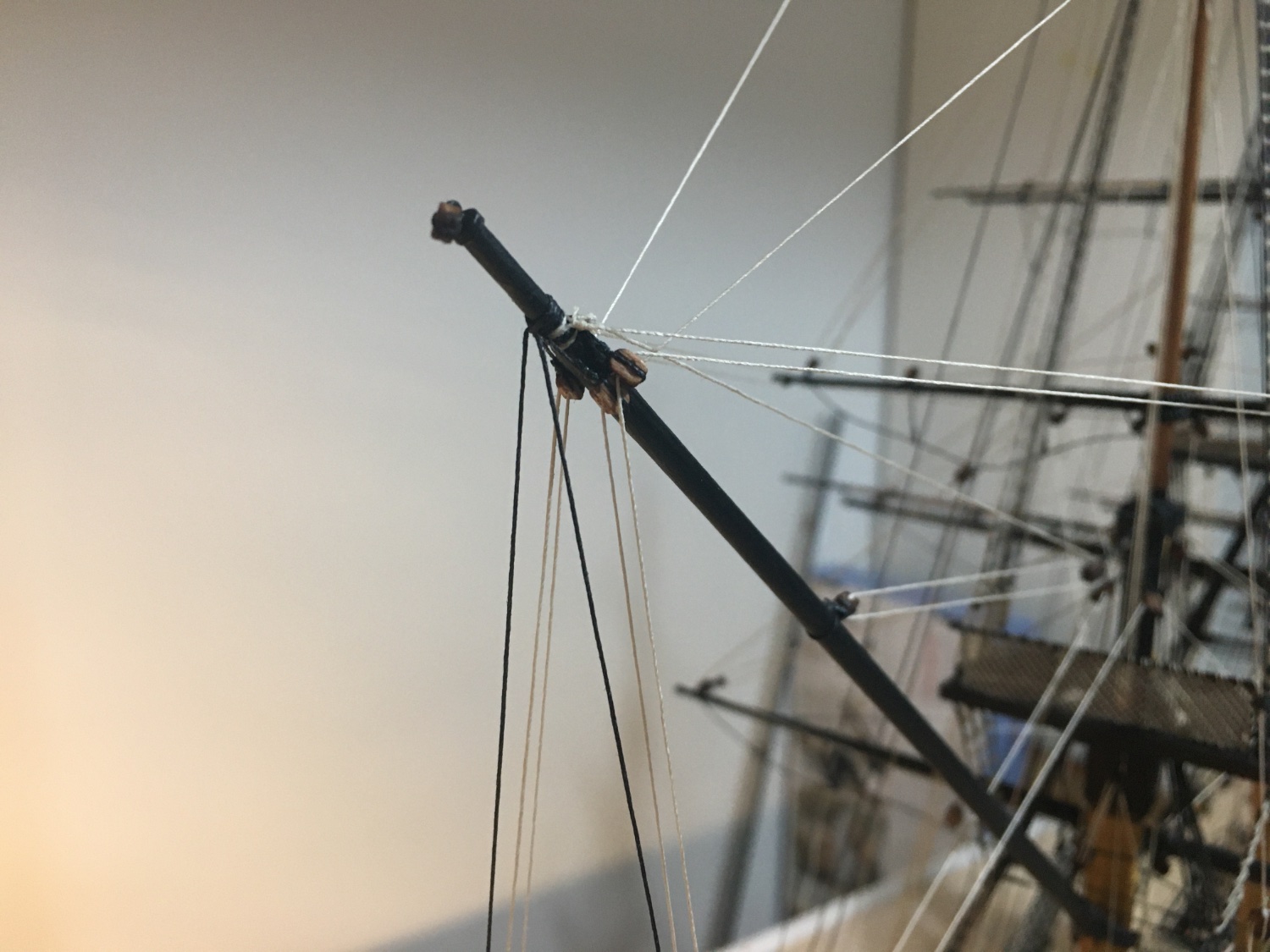
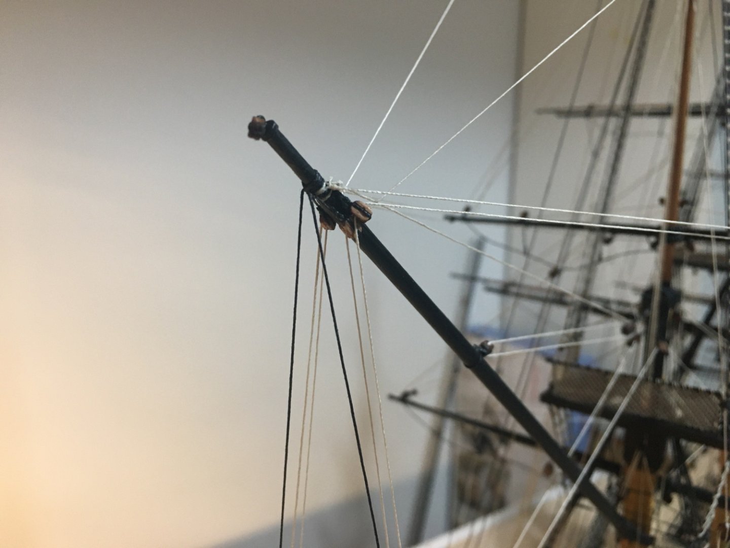
Driver Gaff and Driver Boom shipped in place. End of Driver Gaff End of Driver Boom Tops railings in place. For the moment only dry fitted just in case I need to remove them. Next step is the rigging of the clue lines, sheets and tacks for the Fore Yard and the Main Yard. I can also start adjusting the yard horses to a sagging look and find a method to start doing the rope coils for all the belaying ends. Robert


- 521 replies
-
- 10
-
-
-
- caldercraft
- victory
- (and 1 more)
-
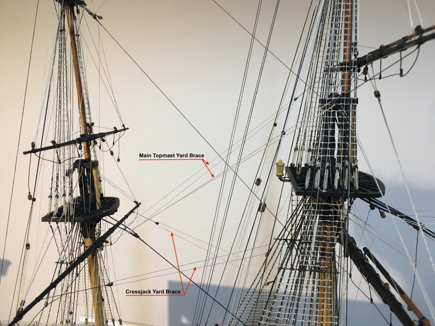
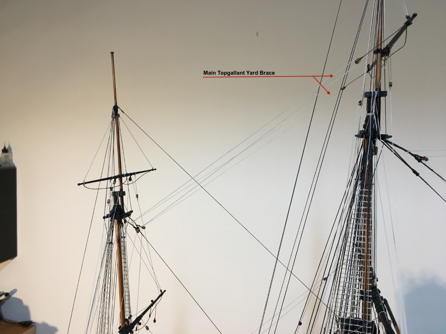
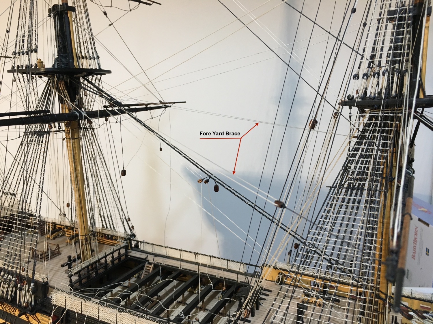
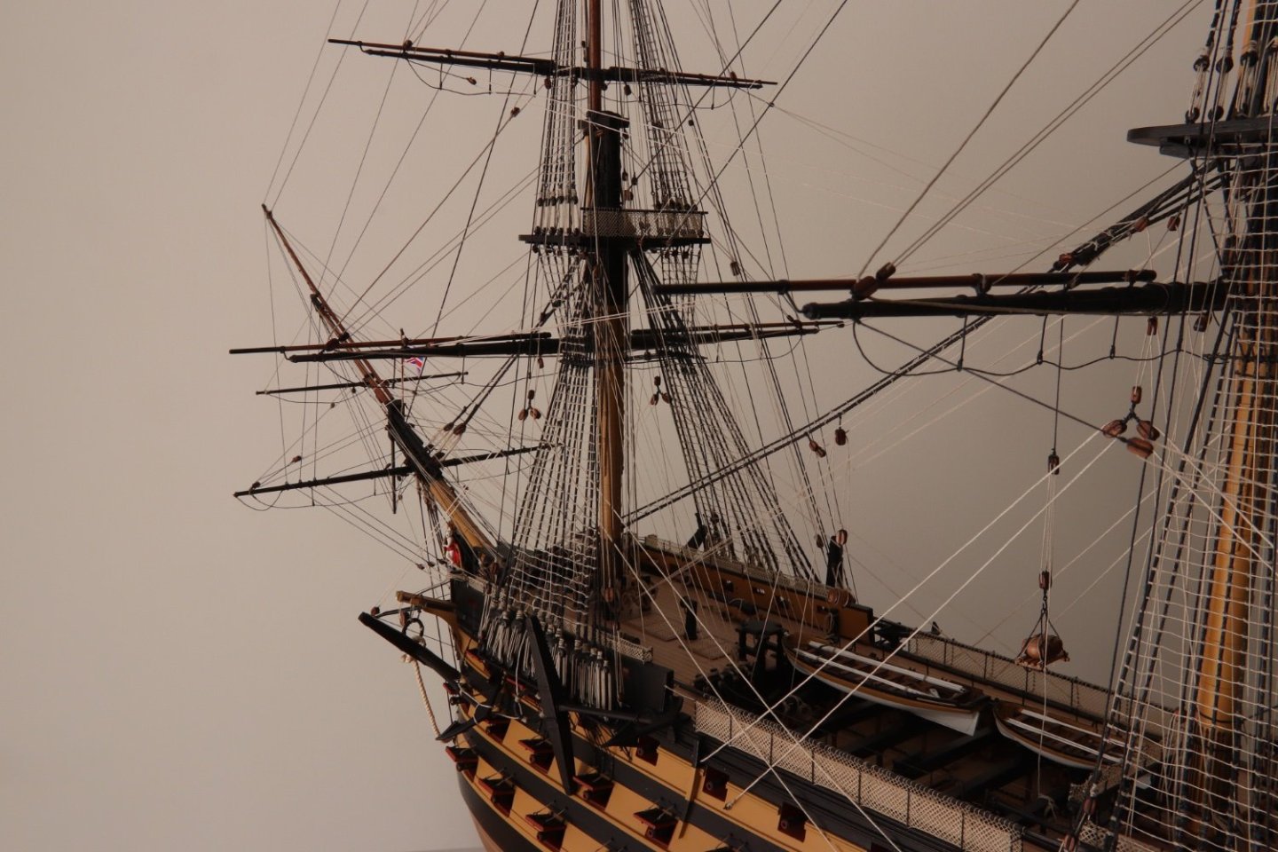
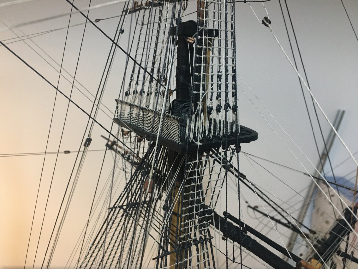
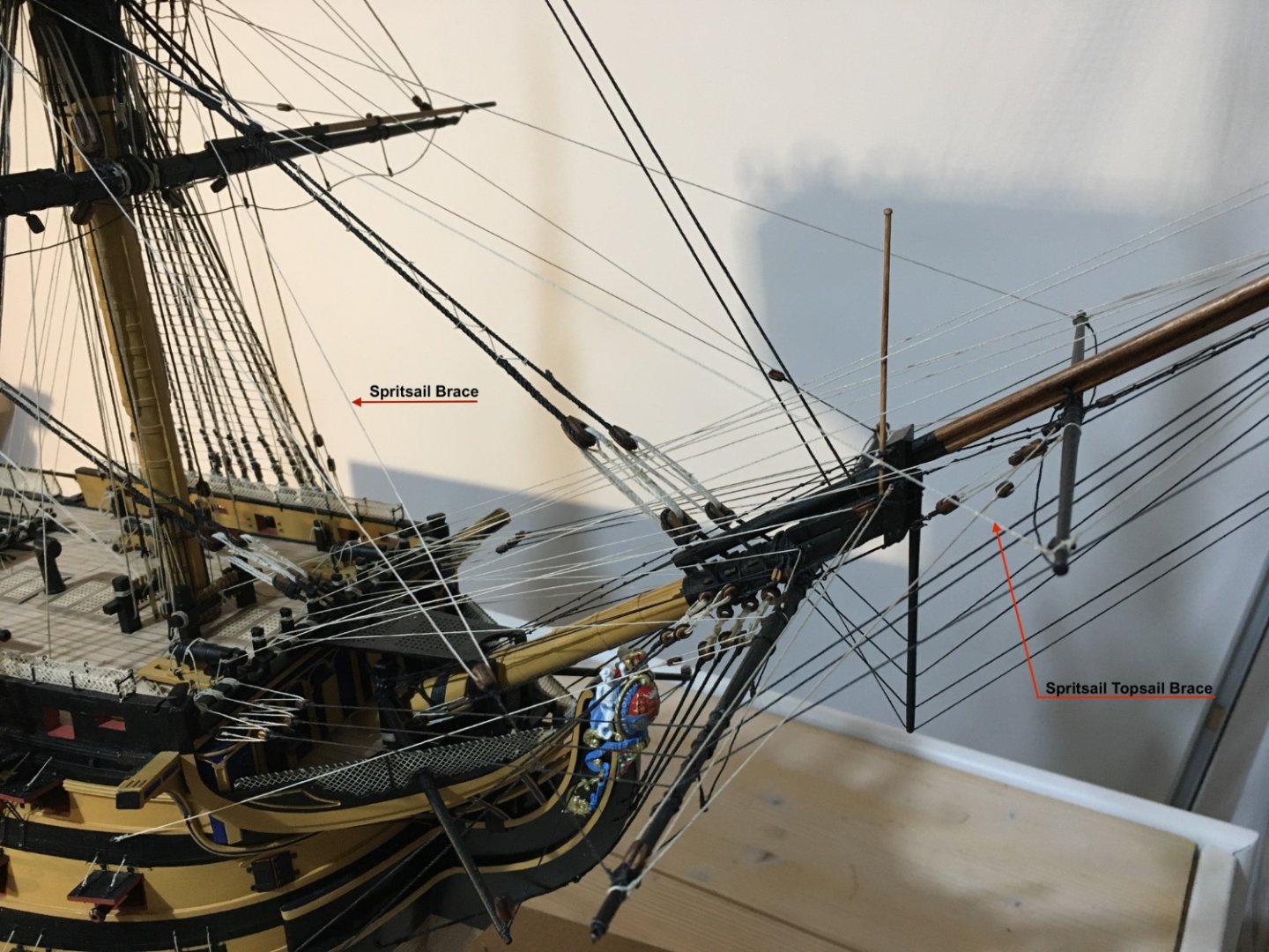
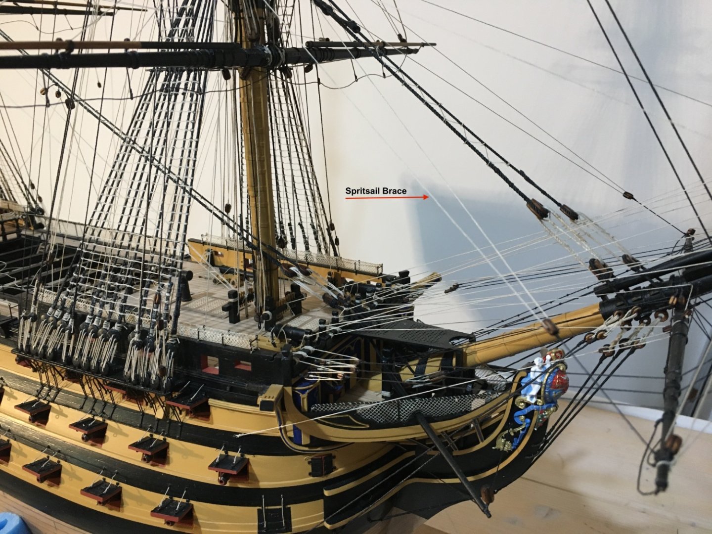
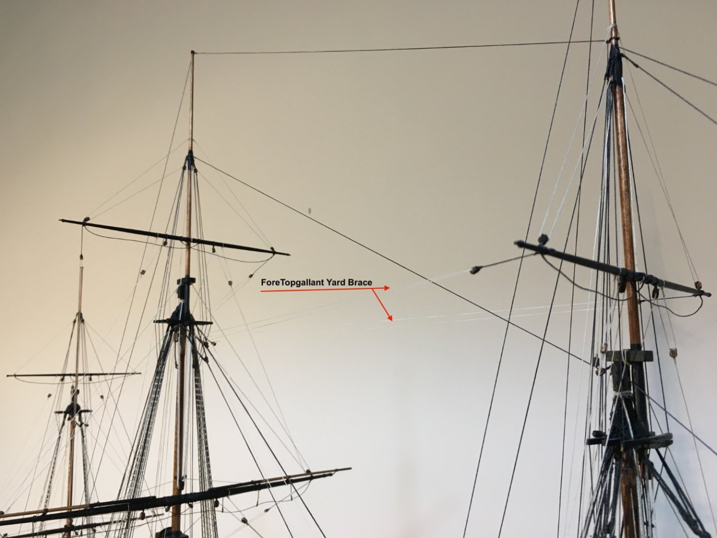
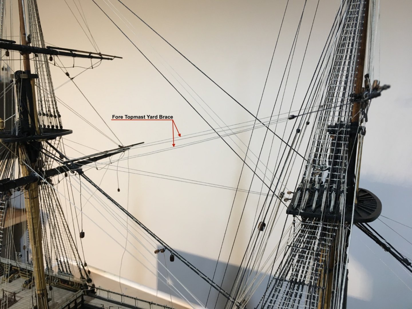
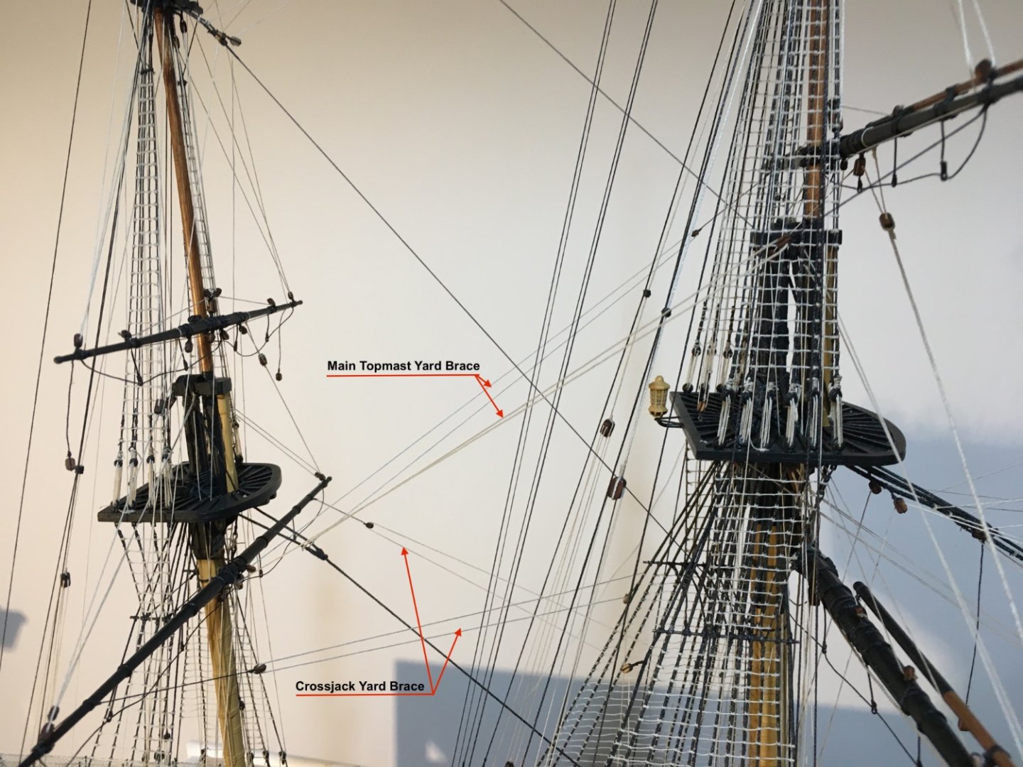
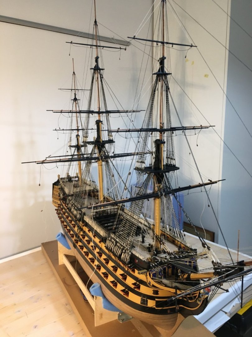
Most of the Braces in place. Spritsail Yard Braces and Spritsail Topmast Braces rigged in place. Fore Yard Braces Fore Topmast Braces Fore Topgallant Braces Main Topmast Yard Brace and Crossjack Brace. Note how the Crossjack Braces cross each other. Main Topgallant Brace. I left the main yard braces loose for the moment as otherwise they will be a bit in the way when installing the Driver Gaff and the Driver Boom. Now I have started work on the Driver Gaff and the Driver Boom which will also enable me to finish the main yard braces, the mizzen topmast braces and the topgallant braces. At the moment the yard horses are haywire, going in every direction. Whilst rigging I keep hitting them so I might as well leave them and adjust them, giving them that hanging effect, when I have all the rigging finished. Robert.


- 521 replies
-
- 12
-
-
-
- caldercraft
- victory
- (and 1 more)
-
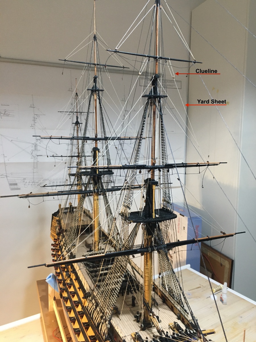
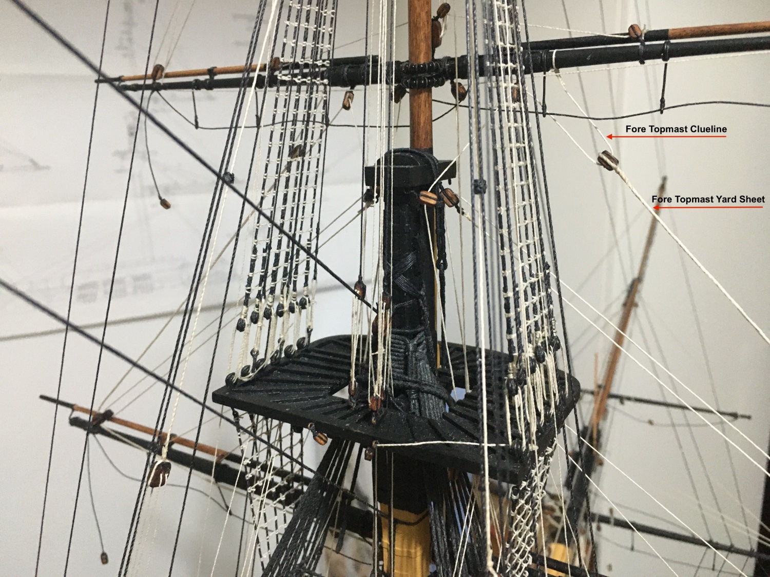
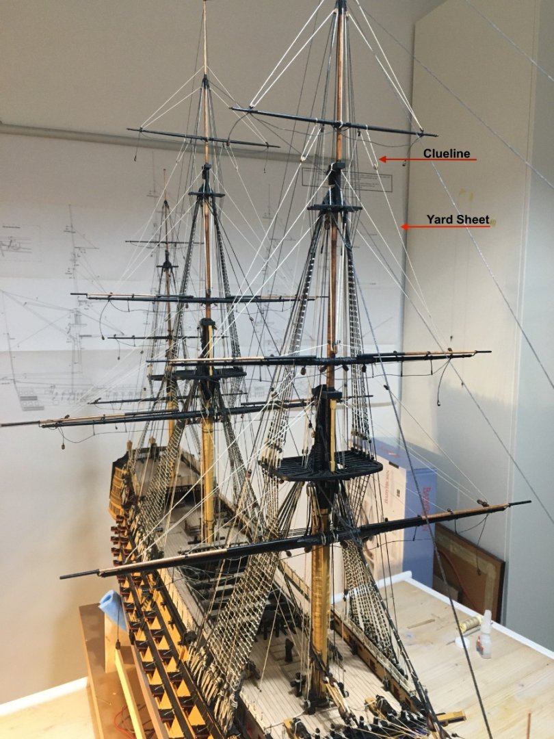
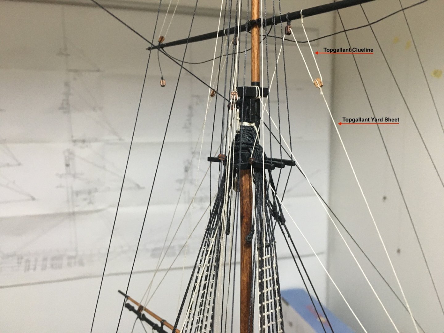
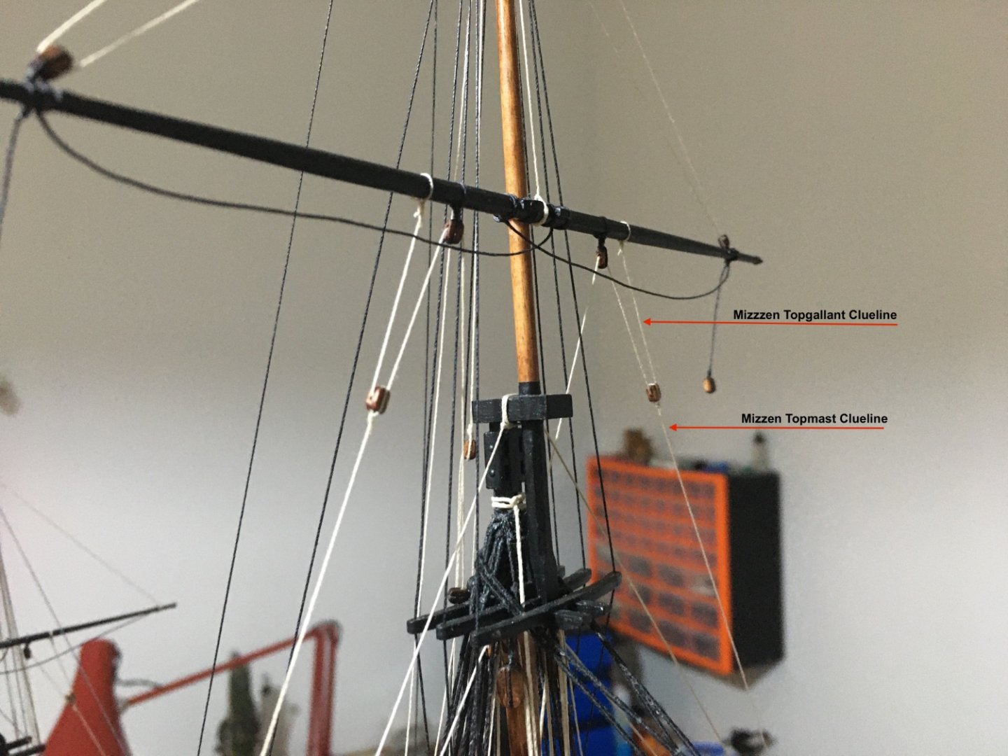
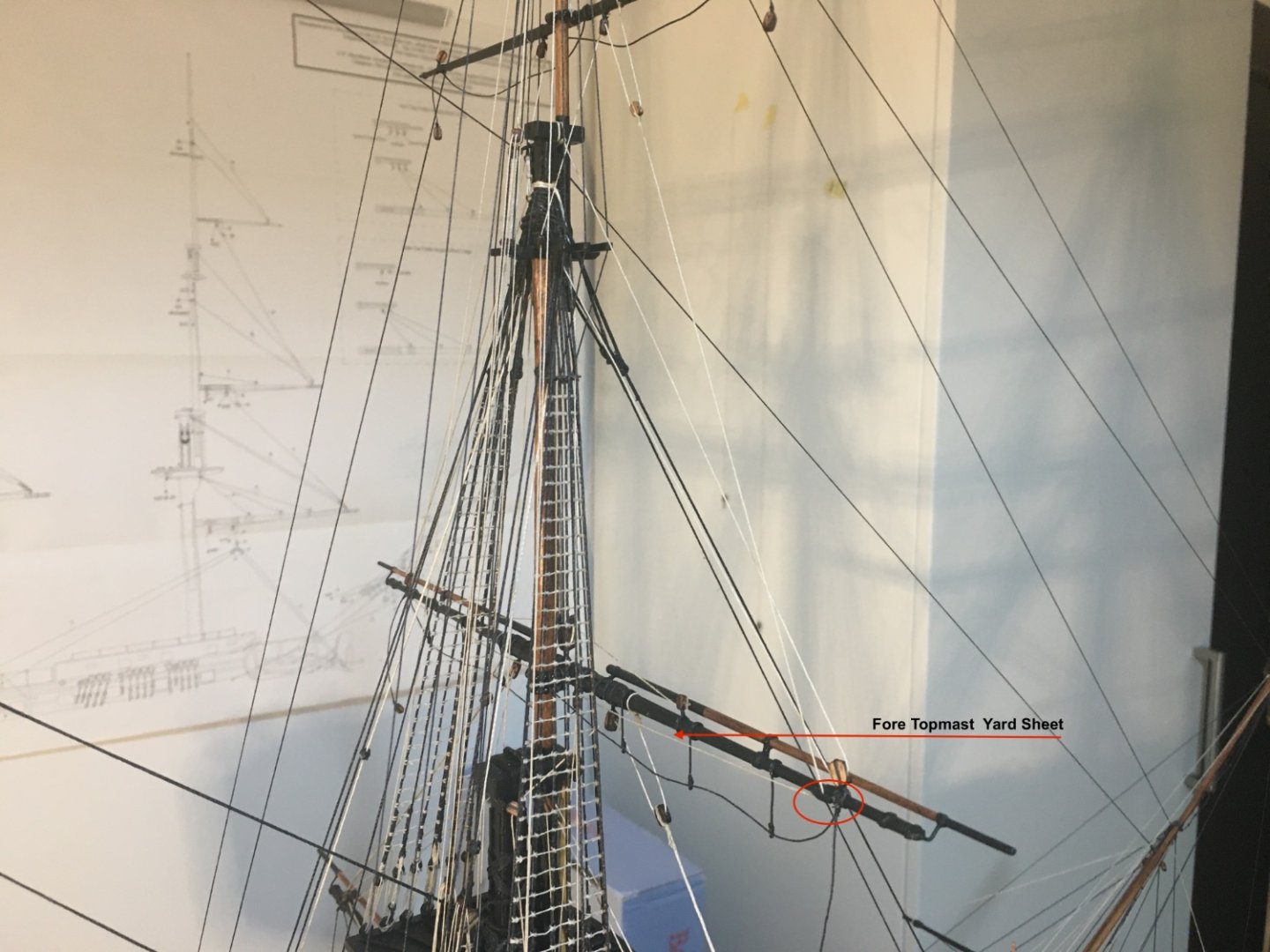
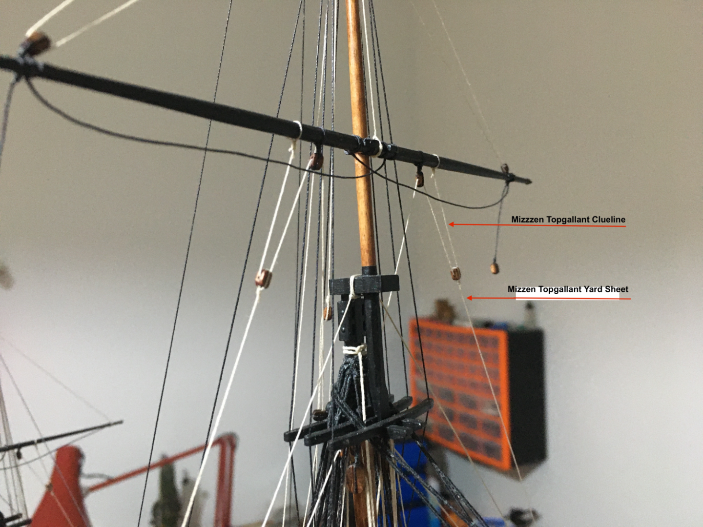
Richard and Malcolm, thank you for your comments and thank you all for your likes. Topmast and Topgallant Yard Sheets and Cluelines ready. Fore Topgallant Yard Sheet and Clueline from the rear. Fore Topmast Yard Sheet and Clueline from the rear. Fore Topmast Yard Sheet. Main Topmast Yard Sheets and Cluelines. Main Topmast Yard Sheet and Clueline from the rear. Mizzen Topgallant Yard Sheet and Clueline. Mizzen Topmast and Topgallant Yard Sheets and Cluelines Now I have to decide if I my next step will be rigging the Yard Braces or else start working on the rope coils. I am thinking that if I don't start fitting the rope coils now it might be much more difficult to reach the pins and cleats when there are more ropes rigged in. Robert.


- 521 replies
-
- 13
-
-
-
- caldercraft
- victory
- (and 1 more)
-
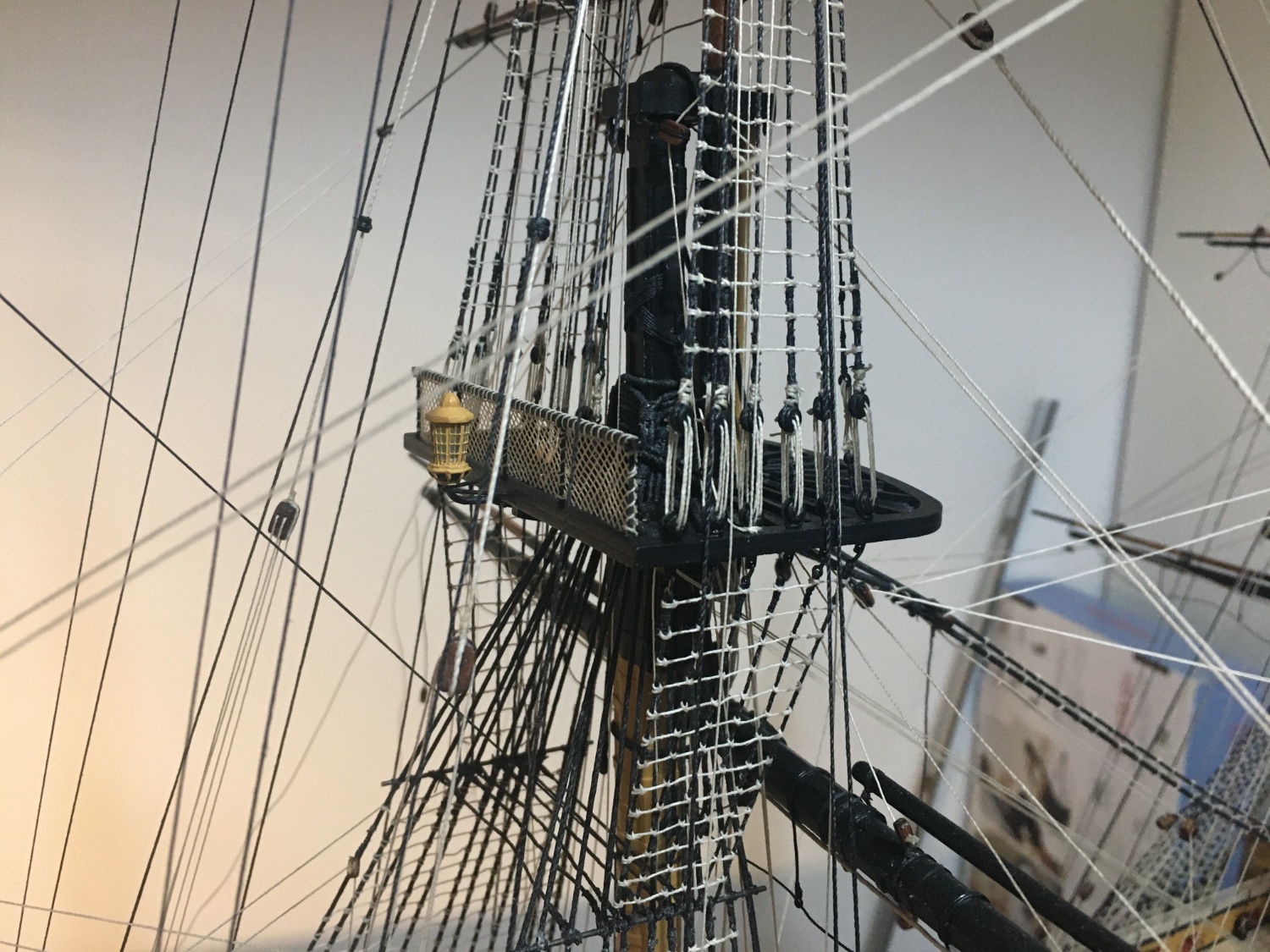
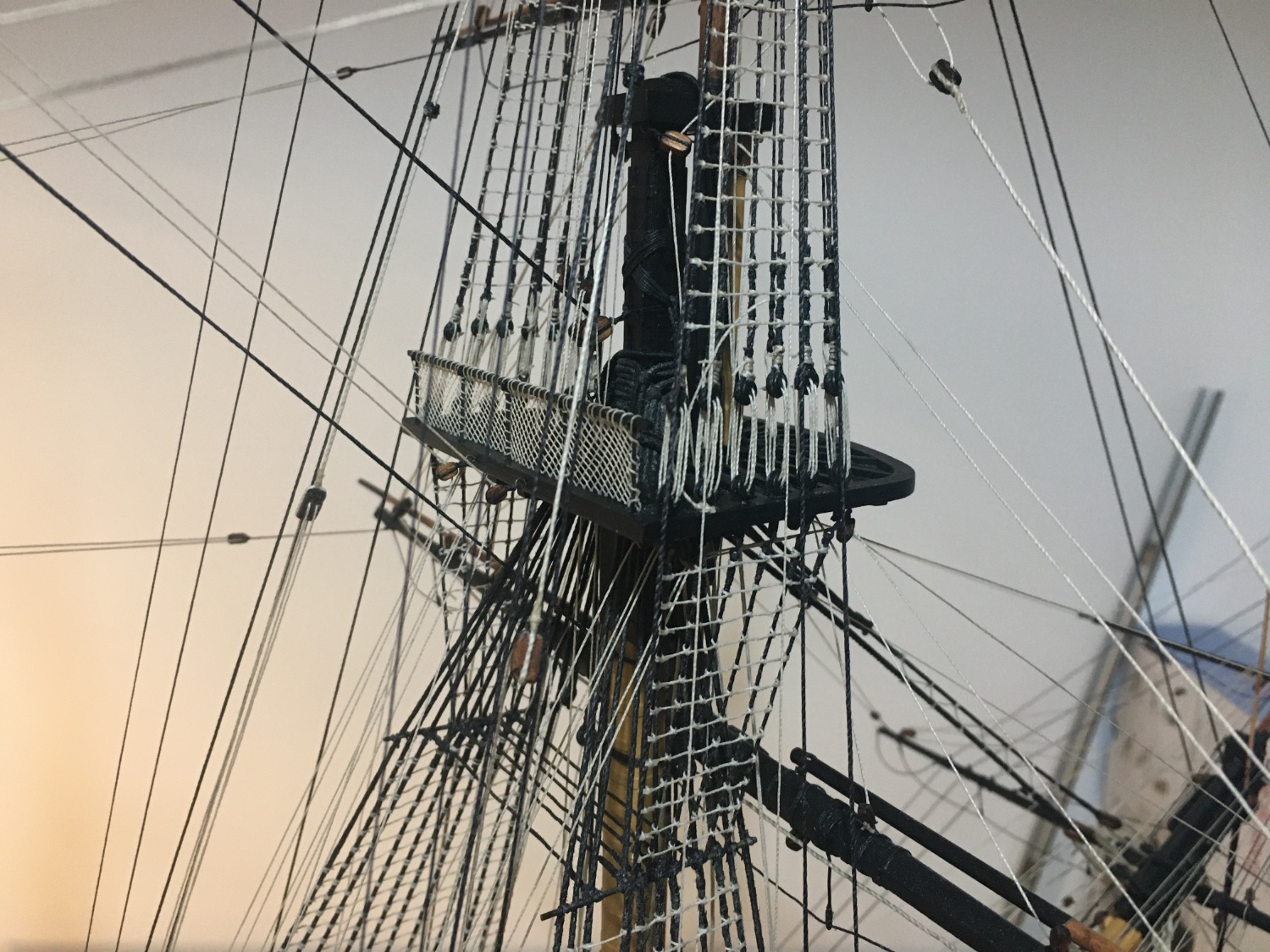
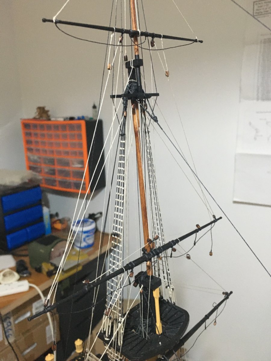
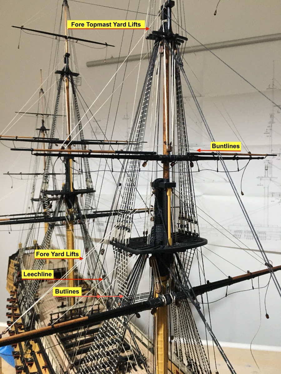
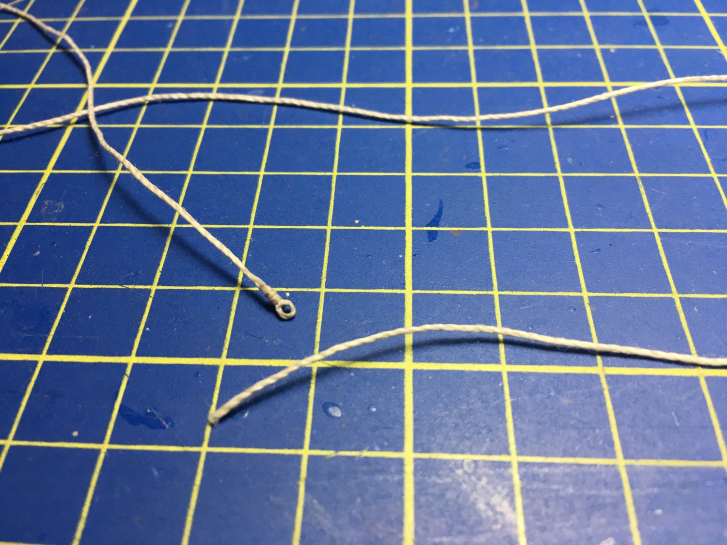
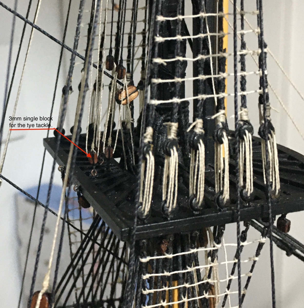
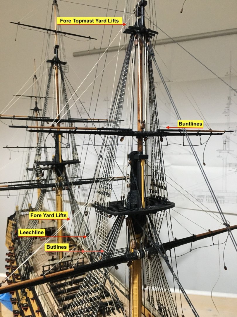
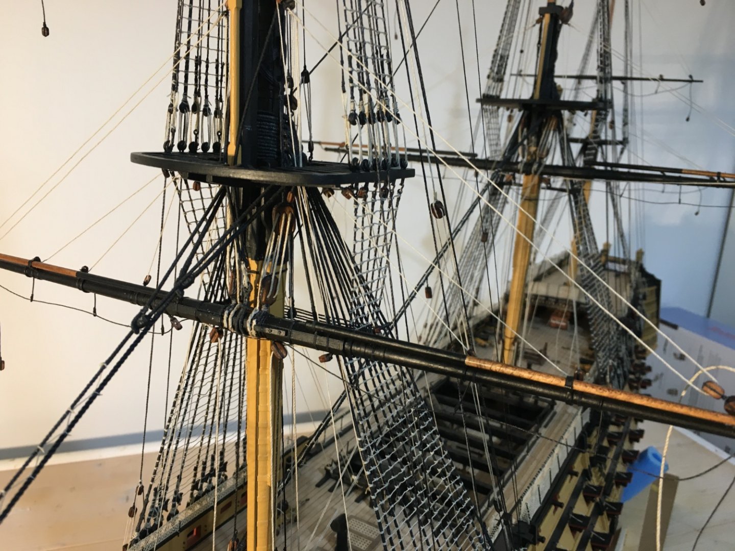
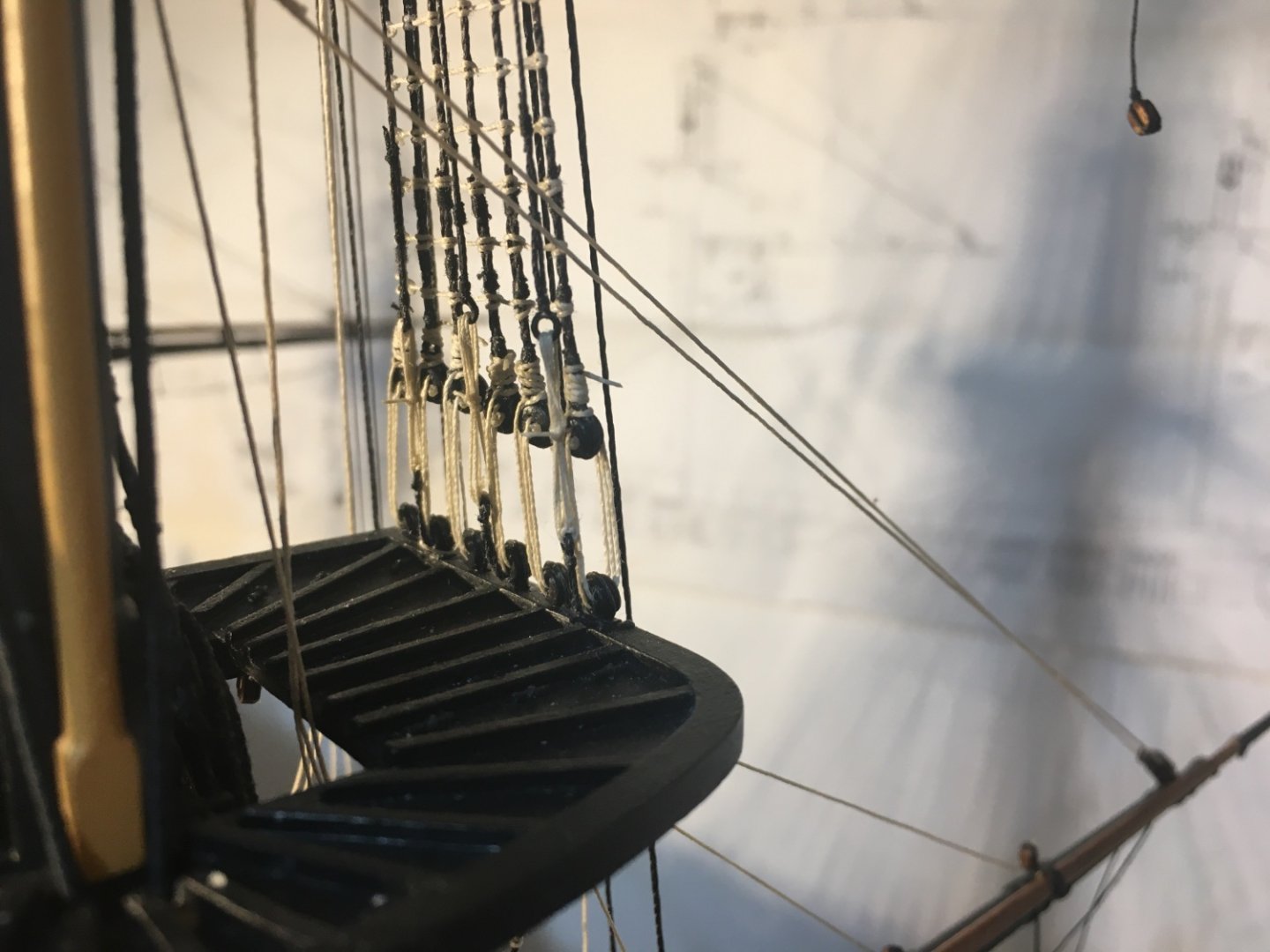
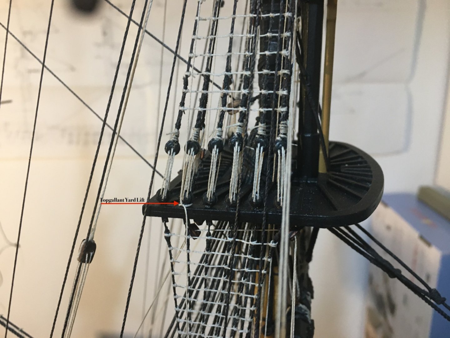
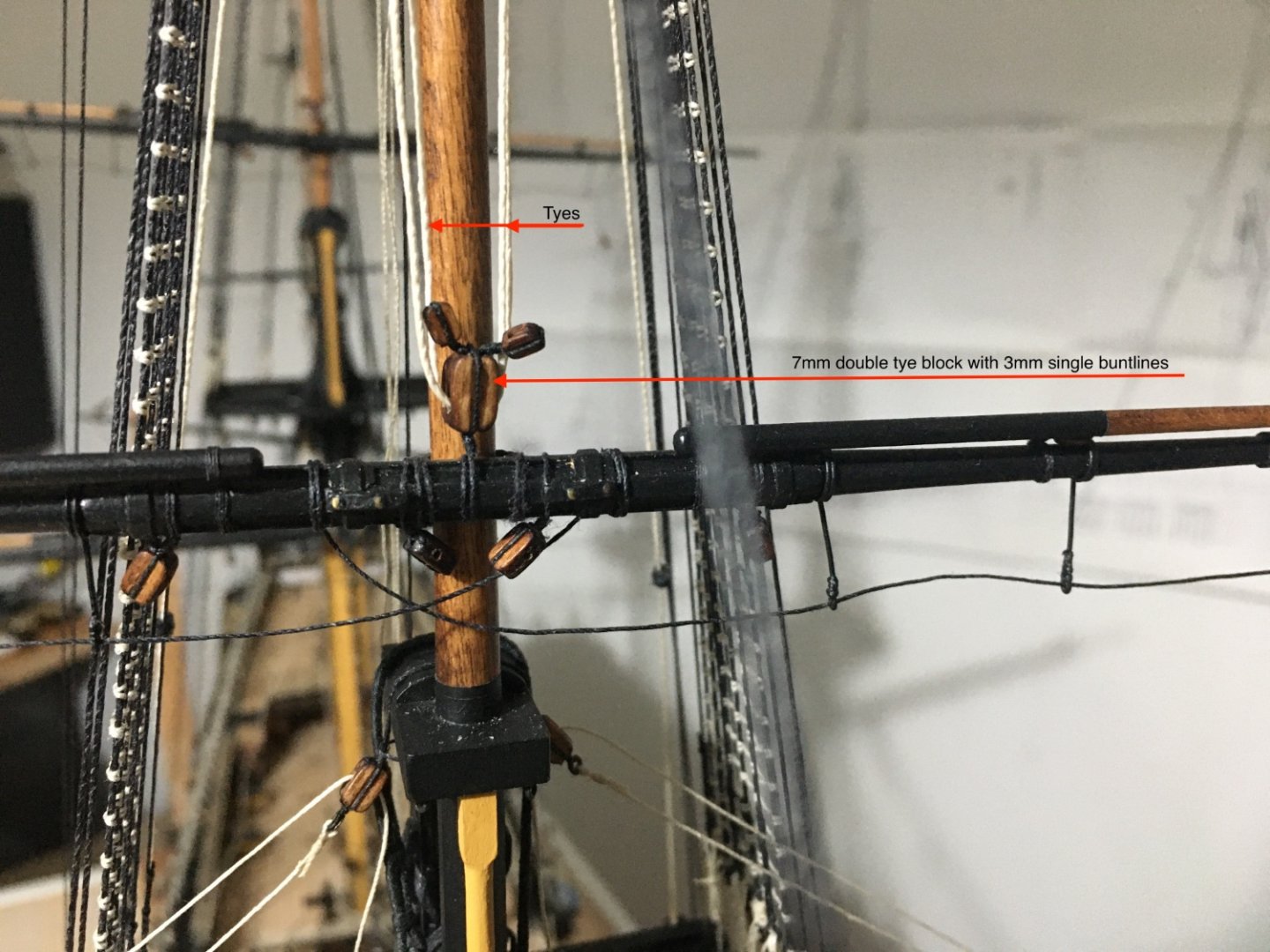
Thank you Bill and thank you all for the likes. Bill, if you go for the LED lights on your Soleli Royal, on the internet you will find a lot of diagrams showing how to wire the LED's, resistors and supply. The major problem is how to install the lights in such small places and avoid any wiring showing. Yard Lifts, Buntlines and Leechlines for the three masts all rigged. Here are a few images. Image showing Yard Lifts, Buntlines and Leechlines on Fore Yard and Fore Topmast Yard. Main Topgallant Yard Lift Fore Yard Lifts, Buntlines and Leechlines. Fore Yard Lifts are belayed to the foremost Kevel on the forecastle. Fore Topmast Lifts and Buntline ends belayed to shroud cleats. Belaying on the Forecastle Breast Beam. Fore Topmast Buntlines, starting with a toggle at the 3mm blocked lashed on the yard. pass through the 3mm single buntline blocks held in a span to the tye block, up to 3mm blocks lashed to the crosstrees and down to be belayed to the shroud cleats. I found it very difficult belaying thread to cleats on the inside of the shrouds. Next step is to rig the yard sheets and the cluelines.


- 521 replies
-
- 10
-
-
-
- caldercraft
- victory
- (and 1 more)
-
Bill / Ian, Thank you so much for your help. Bill your rigging is outstanding. Many times I sourced help from your log, details exchanged between you and Ian, especially when I was doing the bowsprit and decided to go for the jibboom and flying jib travellers which were not even mentioned in the kit manual. Yes, Ian is right, scale makes a lot of difference. Caldercraft Victory is 1:72 and it does help to add more detail. The first kit I did was 1:200 and some detail there is no way you can replicate. Back to the Victory, so although I have cleats on the lower mast shrouds, to use the same size on the Topmast shrouds will look too big, and to make smaller once and rig them I think it is difficult, so probably I will belay round a deadeye. In my opinion, sometimes it is better to omit some detail when its too small to replicate then to do it and doesn't look good or very out of scale. Thanks again Robert
-
Bill and Ian, thank you for your reply. I do have a copy of Lonridge and it has been indispensable for me. Ian, I am under the impression that the lashing you described is just for the Topgallant Shrouds (standing Rigging). In fact that is the way I did the Topgallant Shrouds as per Longridge, totally different from the Kit manual instructions. Thimbles are no problem because I found a way to make them myself from very small brass tubes. The one I am enquiring about is the Lift Ropes coming down from a block seized between the first and second topgallant shrouds. In Longridge the lifts come down from a thimble seized between the first and second topgallant shrouds. But now it is too late for me to change it from a block (as advised in kit manual) to a thimble (as described in Longridge). In Longridge, page 249, subheading Lifts, last sentence, .......leads down into the top and belays round a deadeye. Lifts being a part of the running rigging I think it should be in a way that it can be untied and adjusted anytime. So I am unsure whether to do it same as for Topgallant shrouds or belay it to round a deadeye strop. Robert
-
Great work on your rigging Bill. I am still struggling with the rigging on my Victory, I am just a little, or maybe a bit more than just a little, behind you. So from time to time, especially when I am stuck, I visit your log to seek help. Maybe you can help me with this one. I am presently rigging the yards and I just fitted the Lifts for the Fore Topgallant Yard and am in a bit of a dilemma where the end of the lift should be belayed. In the kit manual it says (....and is secured to a futtock strop on the fore top.). In the Longridge it says (....and belayed round a deadeye.) So I am assuming this is where it should be belayed on the Fore Top. Can you please confirm if I am right. If so I will belay them there and leave some sort of a coil as well. Hope you don't mind me posting an image on your log, if you want I can remove it. Thanks. Robert
-
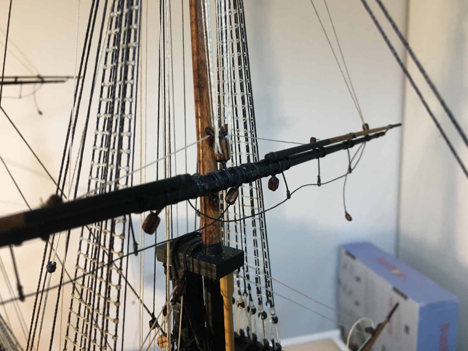
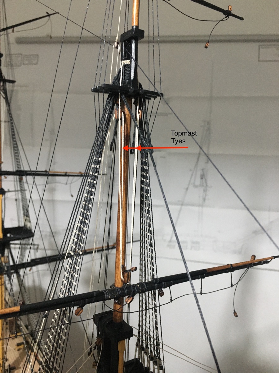
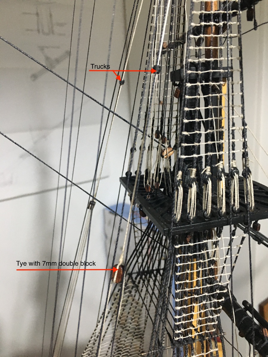
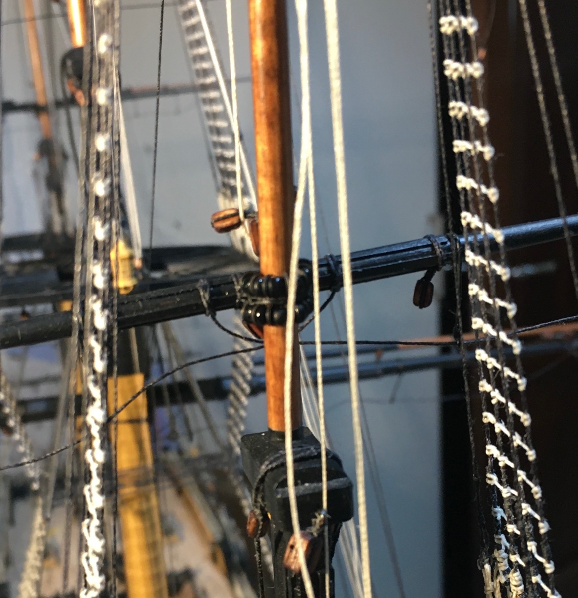
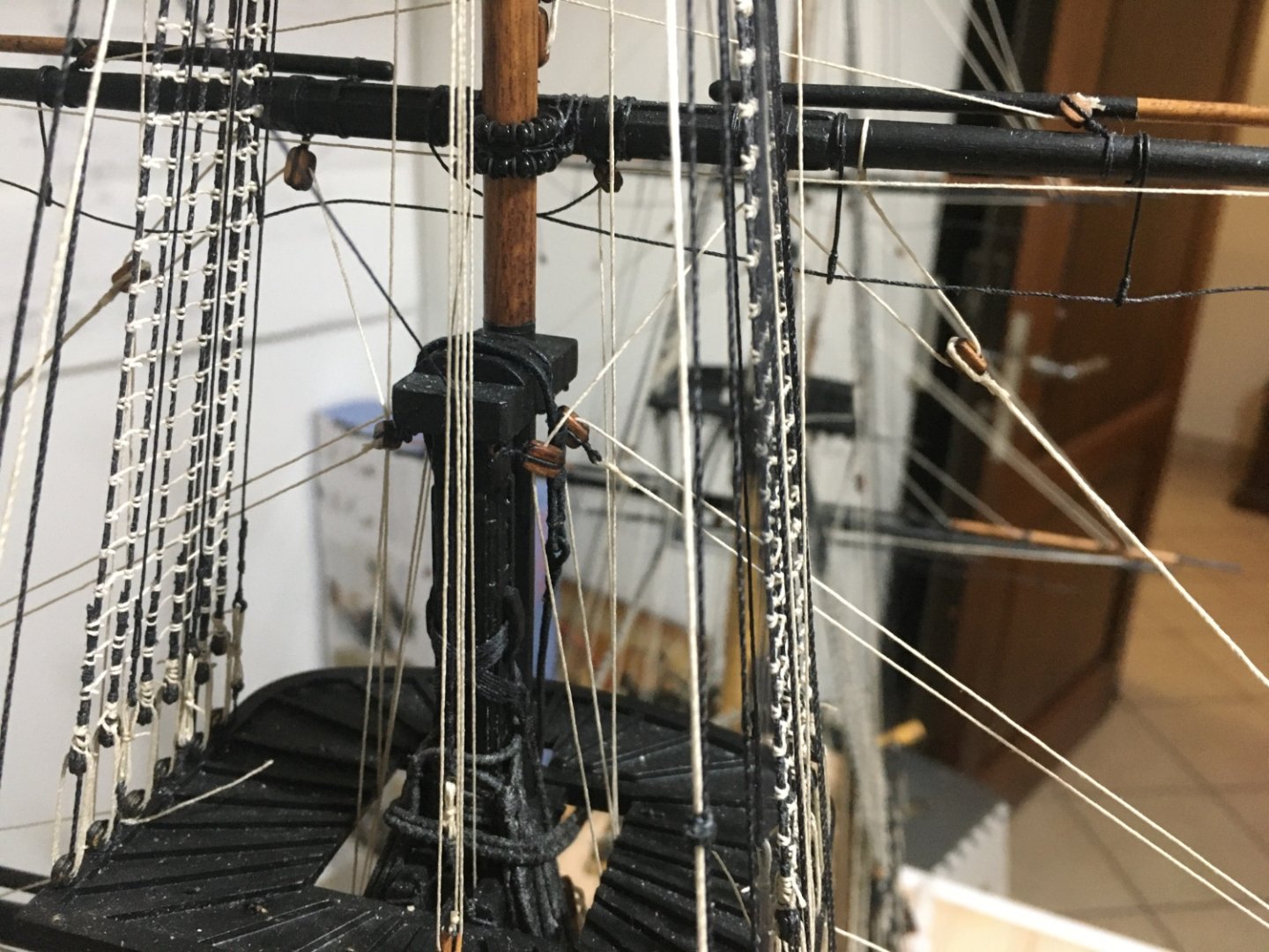
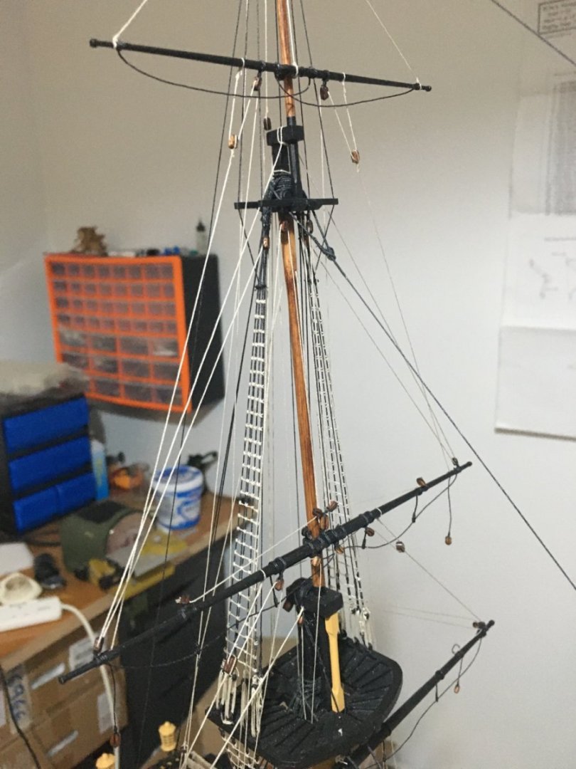
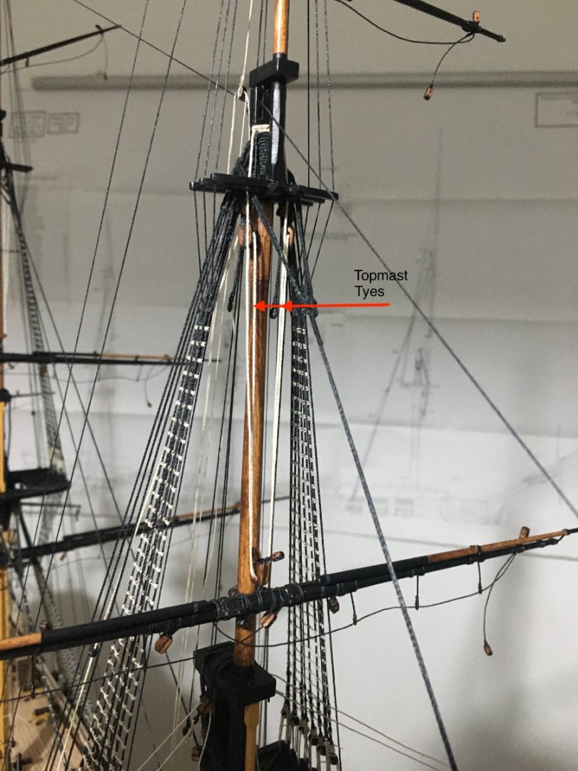
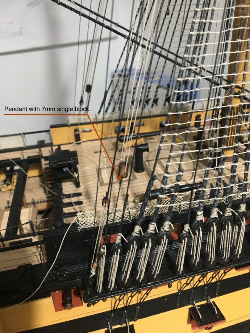
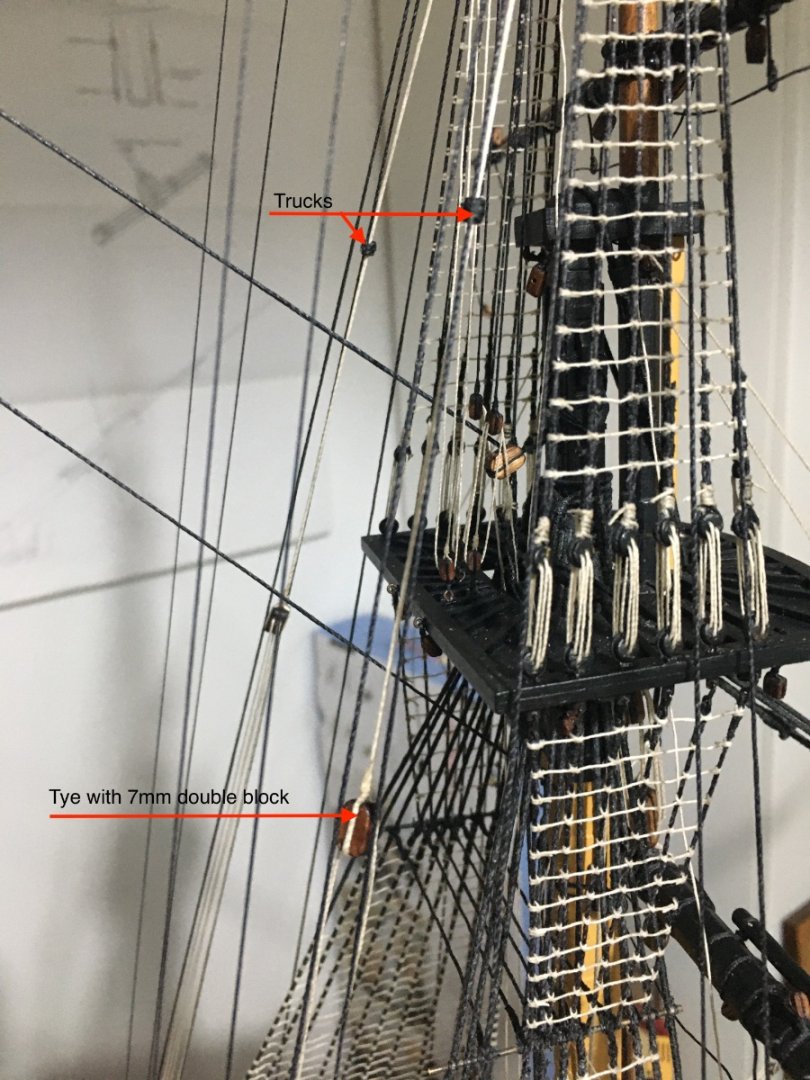
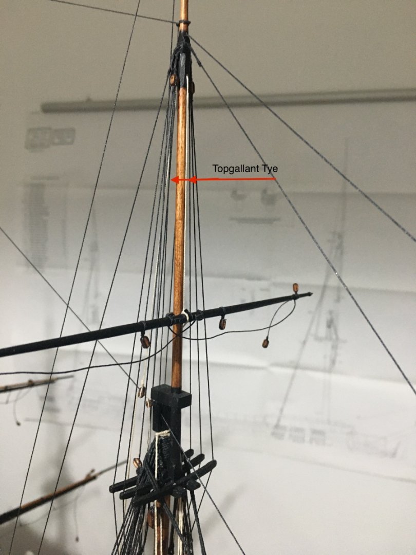
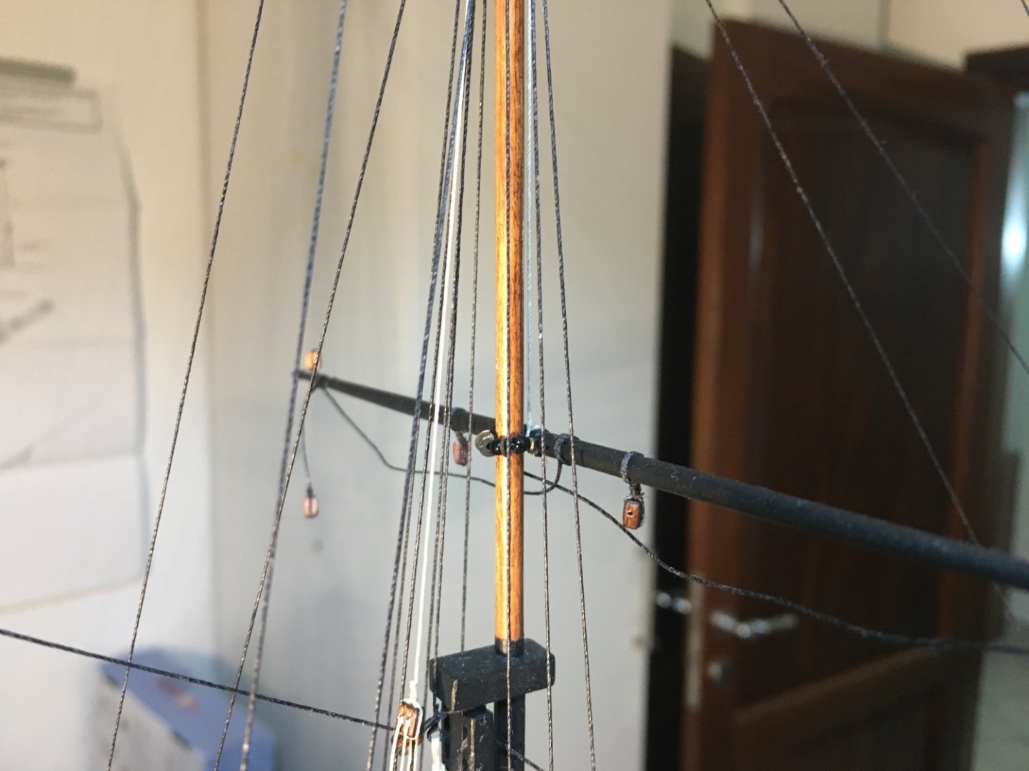
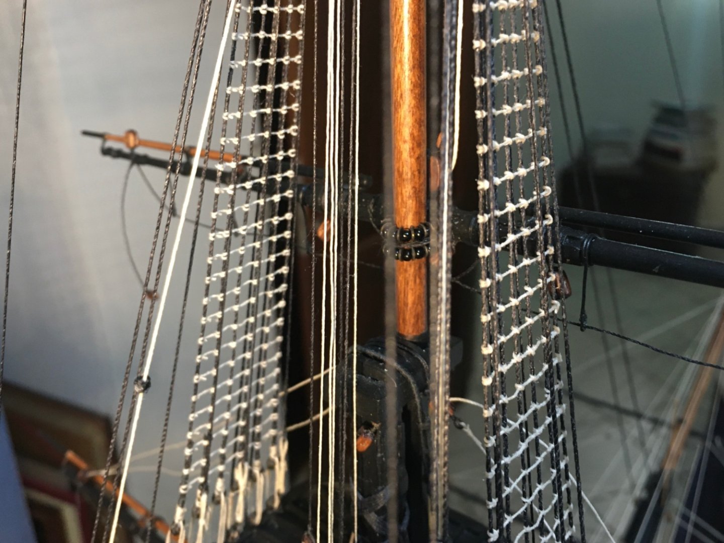
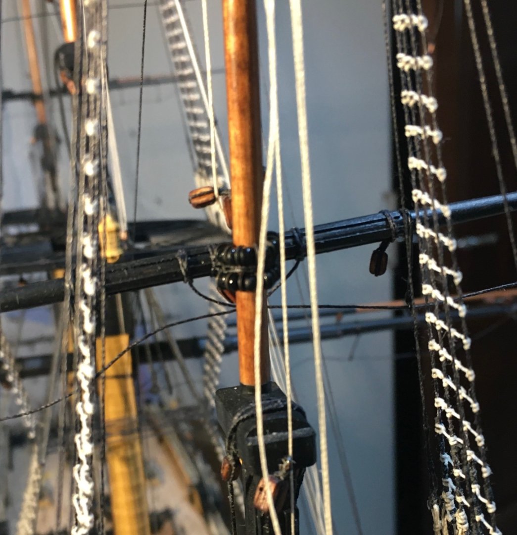
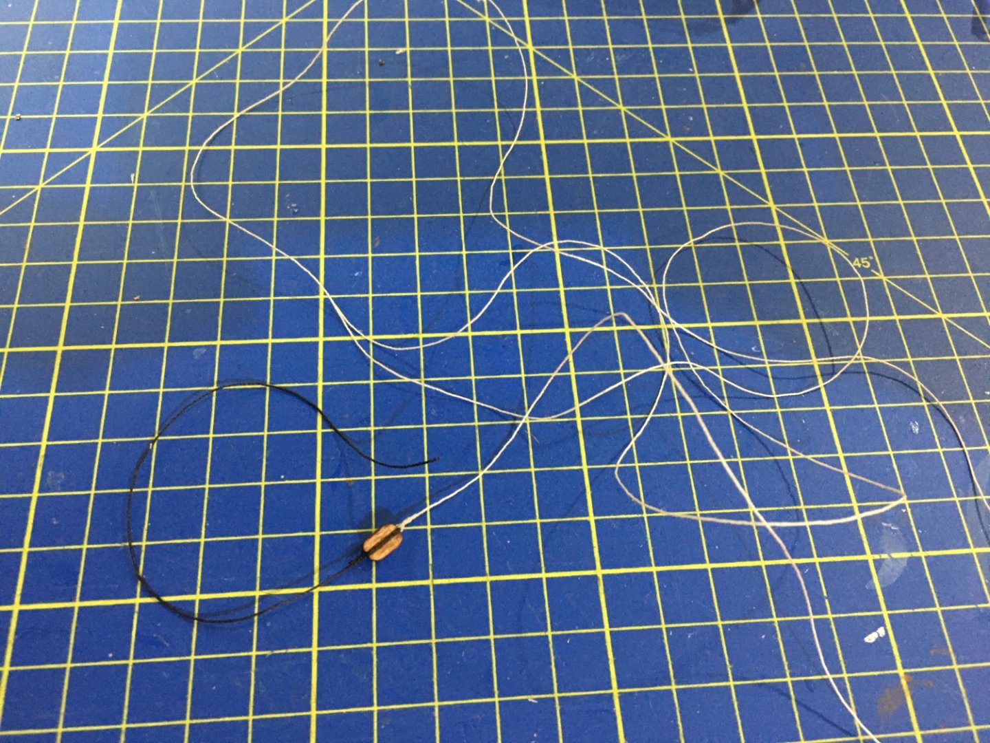
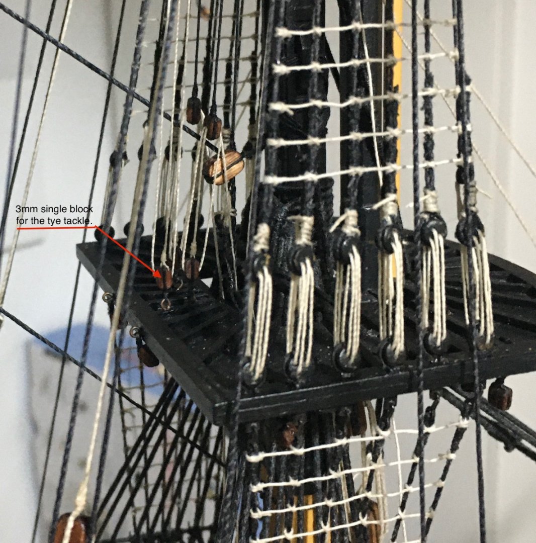
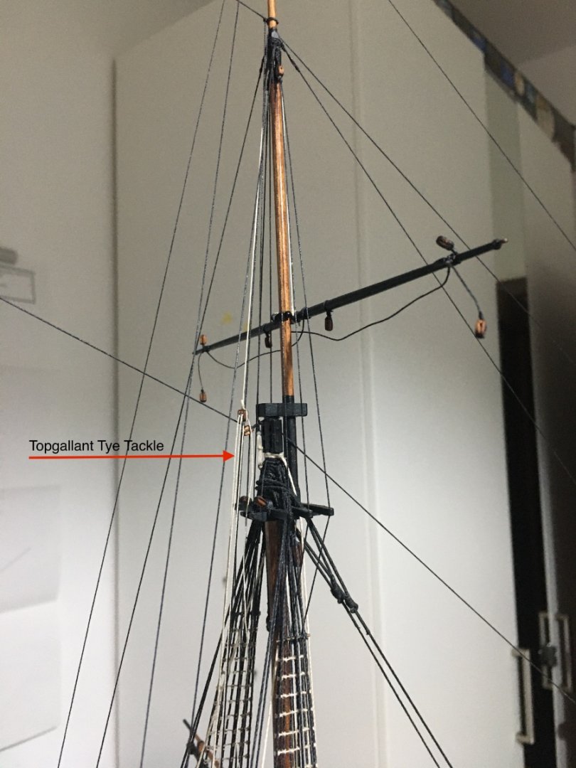
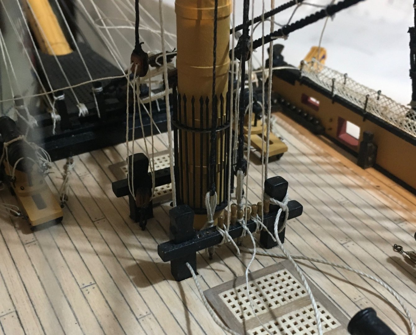
More work on the yards. All yards for the three masts in place and their respective rigging in progress. Still a long way to go, but little by little getting there. Belaying the lines to the bitts is taking me ages. If anyone has a good idea how to do them is more than welcomed to share it. Basically now I have all the truss pendants, jeers, parrells and ties for all yards in place, except that some of them still need their ends to be belayed. I think I will not belay them for now until I rig the lifts, which will keep the yards more stable and in place. For now I am also not bothering about the exact sagging effect of the yard horses as while doing the rest of the rigging I keep hitting them and, so I will set them later on. Fore Topmast Parrells. Mizzen Topmast Parrells Fore Togallant Parrells Topmast Tyes prepared with an eye at one end so that it will be looped to the mast. Pendant prepared for the tye tackle. Tyes secured to mast, go down to the 7mm tye block, up again to a 7mm block, down again through a truck. Tye passes through truck attached t the topmast standing backstay and a 7mm double block seized at the end of it. Pendant seized in place to the eylet at the rear of the channel and a tackle is formed. Foremast Topgallant Tye tied to the middle of the yard, up and through a hole drilled in the hounds, down again and a 3mm double block is tied to the end of the tye. Block on Fore Top to form tackle. End of tackle goes down through the top to the deck. Belayed to the 7th pin. The rest of the Tyes are rigged more or less the same way, with obviously some difference such as belaying positions. I am missing one truck so the tye for the Mizzen Topgallant has to be put on hold until I receive a new one. My next step is to work on the lifts, buntlines and leeches but I think I will take a short break, working through all those lines I am starting to see double.🤩 Robert

- 521 replies
-
- 11
-
-
-
-
- caldercraft
- victory
- (and 1 more)
-
Wow, great work on the stern fascia and the quarter galleries. Glad you took the extra work on the quarter galleries to create that bit of depth in the windows. It makes such a difference. When I was doing mine as per manual instructions I was so disappointed with the result and just couldn't leave it like that. Keep up the great work Graham. Robert