


Roger Pellett
-
Posts
4,519 -
Joined
-
Last visited
Content Type
Profiles
Forums
Gallery
Events
Posts posted by Roger Pellett
-
-
I highly recommend the book Gondola, An Extraordinary Naval Architecture, by Carlo Donatelli (listed in Wefalk’s comprehensive bibliography above). This large, beautifully produced book covers gondola design and construction in detail. The book was originally published in Italian but my copy is an English translation.
The book mentions a set of gondola plans in the Museo Storico di Venezia that the author translated into a CAD file.
Roger
-
Copper sheathing was attached to ships’ hulls with copper nails, not rivets. At a scale of 1:64 a 1/2in nail head would scale less than .01in diameter (less than .25mm) and the head would barely protrude from the surface of the plate. The embossed nail heads on the plates that you show above are way over scale. At this scale, I would question to show fastenings at all.
Roger
-
-
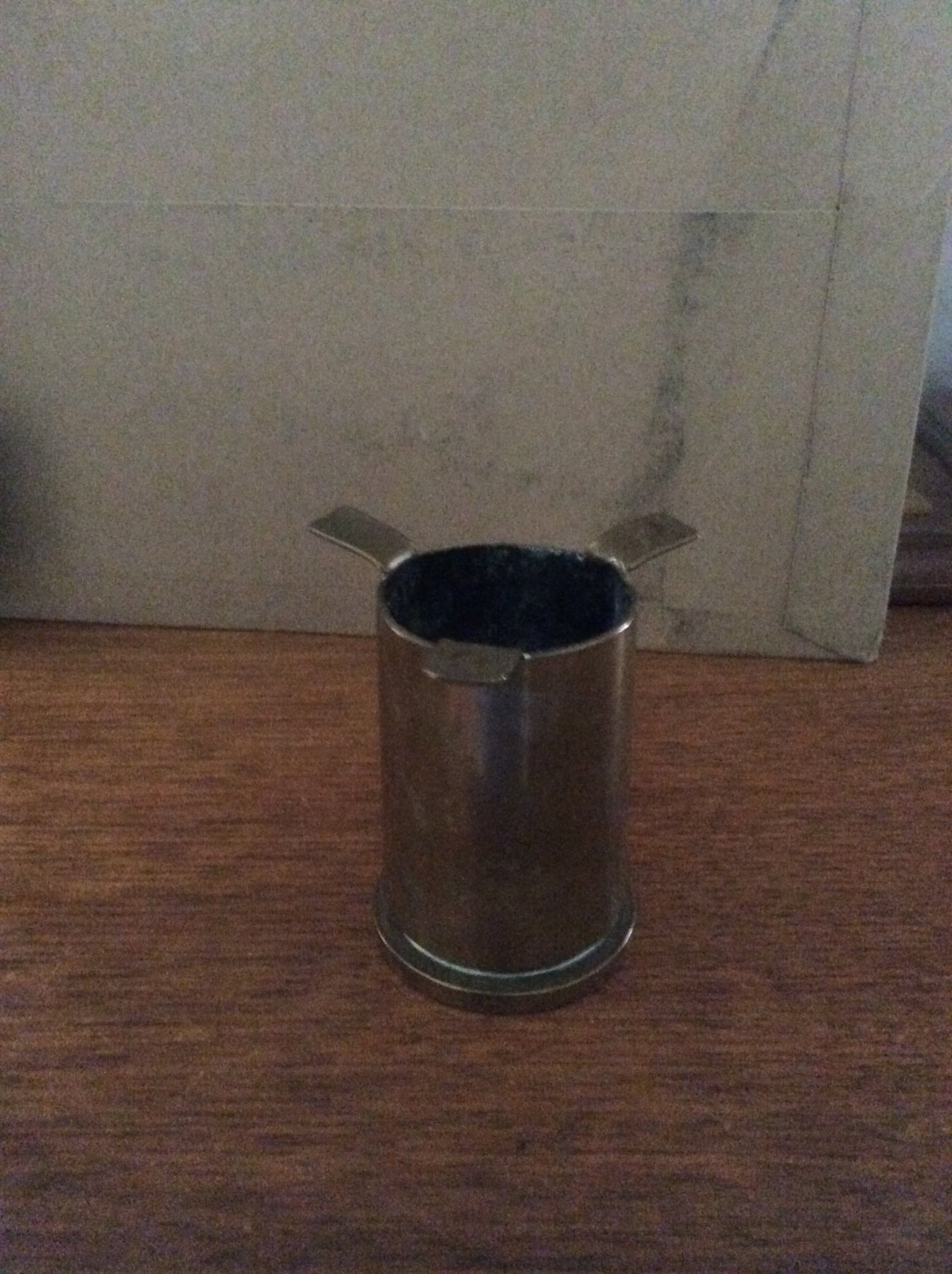
Some of them were made into ash trays. My father-in-law brought this one back from Florida Island in the South Pacific at the end of WW II.

- popeye the sailor, Omega1234, Canute and 1 other
-
 4
4
-
Iron oxide pigment was available in the 1700’s and still is used to produce a cheap construction primer. During my working career it was used as a temporary coating for industrial prefabricated piping that would be insulated after erection on site. It produces the typical “barn red” color. When the VOC regulations were implemented suppliers were able to produce it as a water based product. It cost about $14 a gallon gallon compared to $36 for more high tech products.
Roger
-
How did the model come into your possession.
Roger
- Omega1234, thibaultron and mtaylor
-
3
-
-
I am pleased to announce the publication today by Wayne State University Press of my first ( and last) book, Whaleback Ships and the American Steel Barge Company. As the title suggests this is a comprehensive history of the design and construction of the 44 whaleback barges and steamships. The book is based on original design drawings, company records, and extensive examination of SS Meteor, the only surviving example of a whaleback ship. Copies are available from the Press, Barnes and Noble and Amazon.
Roger
-
-
Since you live in the US, why bother to change to metric. At 1:96 scale, 1/8in represents 1ft. 6in is half of a ft or 1/16 in at scale. 1/16 in basswood sheet stock should be readily available at most hobby outlets to be ripped into planks.
What about the extra inch? Planking is 7in, not 6in. 1in at scale is 1/96in, about the thickness of a sheet of paper. I personally would not worry about this small difference in order to be able to use readily available commercially available sheet stock.
For general measuring, I agree with druxey, buy an inexpensive architect’s scale. The triangular type available at office supply stores will include a 1/8 inch (1:96) scale.
Roger
-
There is a series of posts for a rebuilding of a model of Constitution built from this same kit. The author of this series is Jersey City Frankie. He really turns a derelict into a piece of art.
Roger
- JerseyCity Frankie, Canute, mtaylor and 2 others
-
5
-
The design, construction, and history of USS Maine is well covered in American Battleships 1886-1923 by Reilly and Scheina. This book includes a photo and outboard profile of Maine’s Torpedo Boat. The authors state that when the boat failed to make its design speed of 18kts it was towed to the Newport, RI torpedo station and used for a while as a training vessel. Unfortunately, the authors do not attribute this statement.
The book’s bibliography includes two references specific to Maine:
”Contract Trial of the Machinery of USS Maine,” ASNE Journal 8 (February 1896)
”The Steel Ships of the United States Navy” SNAME Transactions, Volume 1 (1893)
Roger
-
-
Maybe you don’t consider it to be one of your best but it’s one of my favorites.
Roger
- Mirabell61, BETAQDAVE, mtaylor and 3 others
-
6
-
Where did you find the lines drawing for the torpedo Boats?
Roger
- lmagna, popeye the sailor, mtaylor and 4 others
-
7
-
Look into easels for children. Places like Blick Art have them. Also Melissa and Doug. We bought these for our granddaughters and while the idea mat sound a bit silly, they are sturdily built and stable.
Roger
- Landlubber Mike, trippwj, alde and 5 others
-
8
-
Here in the US the Naval Institute Press recently published The Life and aship Models of Norman Ough. I assume that this is the same book that you are reading and I really enjoyed it. Although some of his techniques are somewhat archaic by today’s standards he achieved remarkable results. Ough was a master of the diorama type display and I particularly enjoyed his discussion of the many small points, some unique to the Royal Navy that can liven up a model.
Roger
- mtaylor, paulsutcliffe and Canute
-
3
-
-
Welfalk,
In the case of my Sherline, I don’t agree. First of all, the arbor that the chuck threads on to has a drawbolt that passes through the hollow headstock shaft that securely locks the chuck in place. Without this drawbolt side forces would cause the chuck to come loose. As to the chuck itself the workpiece is locked into the chuck with the chuck key, and the lathe itself is not intended for heavy cuts in hard materials.
Roger
-
Since there has been considerable discussion of lathes, milking machines direct read outs, and CNC lately I thought it might be worthwhile to present some thoughts on the way that I have used machine tools. For a number of years I have been interested in building a series of warships’ boats to a common scale of 1:32. My comments apply to scratch building of these models. If you are say turning a set of identical cannon barrels your needs may be completely different.
Almost 20 years ago I bought a Sherline long bed lathe and milling column to replace an ancient Sears metal lathe that had died. The Sears lathe did have two features that I thought that I wanted that the Sherline lacked: power feed, and a tail stock that could be set over to turn a taper. As it has turned out I have not needed either of these features. I have also found that that my work has not required a vast assortment of accessories.
Chucks and hold downs:
For most of my work, I use a 1/2 in Jacobs chuck attached to a Morse tapered shank that fits into the headstock. I also have a Sherline three jaw chuck but have only needed to use it two or three times.
I also have a set of fractional collet chucks that are great for machining fractional sizes of brass rod. If I have rod that matches one of these collets I use it.
Another highly useful and inexpensive accessory is a set of T nuts and hold downs. While their application to the mill is obvious they can also be used for making fixtures, sometimes from plywood that can be clamped to the tool post. I recently needed to drill a hole longitudinally down an oar shaft to fit a handle. Freehand made a mess of things. I made a U shaped bracket from plywood and mdf, held down to the toolpost with T nuts. A drill equal to the oar shaft diameter was chucked in the headstock and by moving the toolpost was drilled through the two uprights of the U. This hole was now centered on the headstock. A smaller drill equal to the handle diameter was chucked and by feeding the oar shank through the holes in the U bracket a hole concentric to the center of the oar shaft resulted.
Drilling:
Many projects involve drilling a hole, and for this a tail stock chuck is essential. I also use the sensitive drilling attachment in the milling column whenever I can.
Turning:
I have a vertical sanding machine with a 1in wide belt ( a linisher to our British friends) that I prefer for grinding lathe tools. I find this to be easier to use than a bench grinder. A parting tool is essential, but I also have a miniature one made from 1/4 in bar stock that accepts a piece of an Exacto blade. While the regular lathe tools are used for turning stock to a diameter or tapering, much detailing is done freehand with needle files.
Calibration:
For much work, I find that cut and try using simple plywood gages is easier than using the calibrated handwheels. For example I recently made a set of belaying pins. The raw material was 1/16 in brass rod. First this was chucked in a 1/16in collet chuck and the shank was turned to 1/32in, the diameter checked with a 1/32in hole drilled in a piece of thin model plywood. It was necessary to turn a short section of rod to its required diameter, then loosen the collet and to feed out another section until the entire shank had been turned. Otherwise it would have collapsed. The head of pin was then shaped with needle files and the pin was cut off with a razor saw. With some ingenuity there are all sorts of simple gages that can be made to produce work of sufficient accuracy.
Roger
-
Ok, I’ll try to explain. The centerboard is under tension caused by the weight of the board trying to pivot it about its pivot pin. We’ll call the tension T. A rope transmits this tension along its length. By changing the direction of the rope a block or pulley fixed to the boat’s structure changes the direction of T but not it’s magnitude. As rigged the force required to raise the centerboard is still T. In fact it is somewhat more than T due to the friction in the pulleys and blocks.
Now, attach the block to the pendent so that it can move back and forth as the centerboard pivots up and down. The force on the end of the block attached to the pendent is still T and while,the TOTAL force on the opposite end of the block must be equal and acting in the opposite direction, it is equally distributed between each of the “legs” of the tackle, in this case Five. The tension in each leg of the tackle including the leg that is secured to the cleat is therefore T/5. We would therefore say that this tackle has a mechanical advantage of 5.
There is however no free lunch. Although the force to lift the board is now 1/5 of what it would have been without the tackle it now requires 5 times the length of pull (length of rope) as before.
I hope that all of this makes sense.
Roger
- cog, thibaultron, Omega1234 and 6 others
-
9
-
-
Civil War warship guns are well covered in Arming the Fleet by Spencer Tucker. Another excellent source is Ordnance Instructions for the U.S. Navy. Copies of the 1866 version is available in reprinted form and online. If you decide to buy a reprint, the Michigan Historical Reprint Series by the University of Michigan are “top of the line.”
Roger
-
Frank,
A beautiful model of an interesting subject. Well done!
A bit of a minor quibble. I don’t understand the centerboard tackle. With the pendant led through the two double bolcks both fixed to the cabin roof the mechanical advantage would be lost. Shouldn’t the pendant be spliced into the end of the forward double block?
The Kit-Basher's Guide To The Galaxy
in Discussion for a Ship's Deck Furniture, Guns, boats and other Fittings
Posted · Edited by Roger Pellett
Re: Stacked Boats
i don’t know what period the above Constitution model represents but by mid Nineteenth Century US practice was to nest the cutters in the 1st and 2nd launches. All of the thwarts in the launches were removable. When in use thwarts were fastened by iron pins into heavy clamps worked into the boat’s interior structure. This allowed the stack of boats to be considerably lowered.
See: William Brady, The Kedge Anchor.
Roger