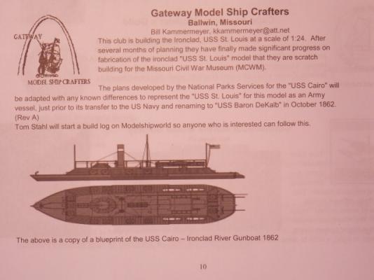
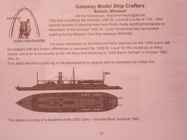
Civil War Ironclad, USS St. Louis - !:24
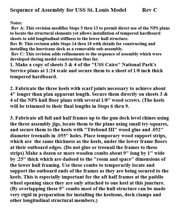
Sequence of Assembly for USS St. Louis Model Rev C
Notes:
Rev A: This revision modifies Steps 5 thru 13 to permit direct use of the NPS plans to locate the structural elements yet allows installation of tempered hardboard sheets to add longitudinal stiffness to the lower hull structure.
Rev B: This revision adds Steps 14 thru 18 with details for constructing and installing the hurricane deck as a removable sub-assembly.
Rev 😄 This revision adds refinements to the sequence of assembly which were developed during model construction thus far.
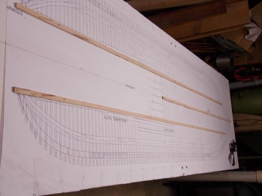
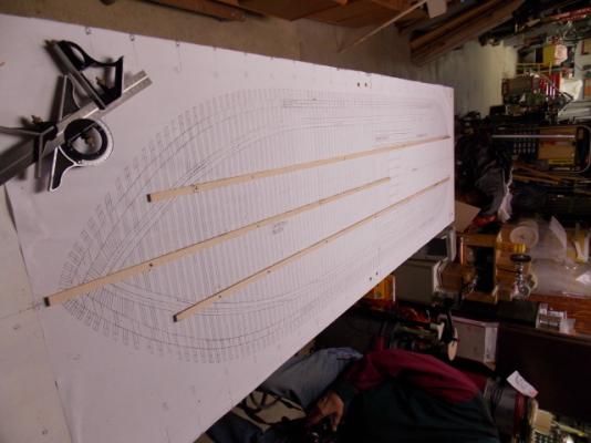
1. Make a copy of sheets 3 & 4 of the "USS Cairo" National Park's Service plans at 1:24 scale and secure them to a sheet of 1/8 inch thick tempered hardboard.
2. Fabricate the three keels with scarf joints necessary to achieve about 4" longer than plan apparent length. Secure them directly on sheets 3 & 4 of the NPS hull floor plans with several 1/8" wood screws. (The keels will be trimmed to their final lengths in Steps 6 thru 9.
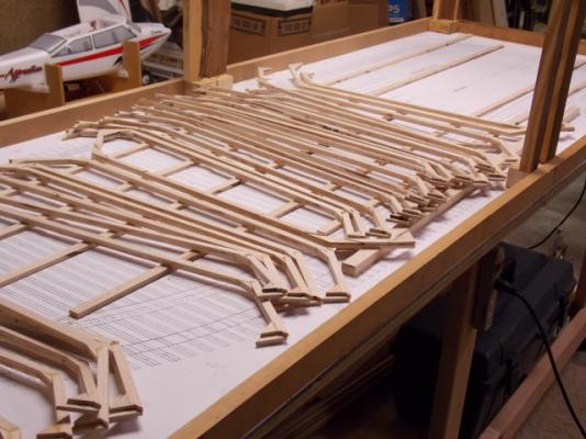
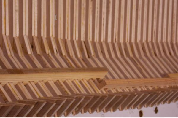
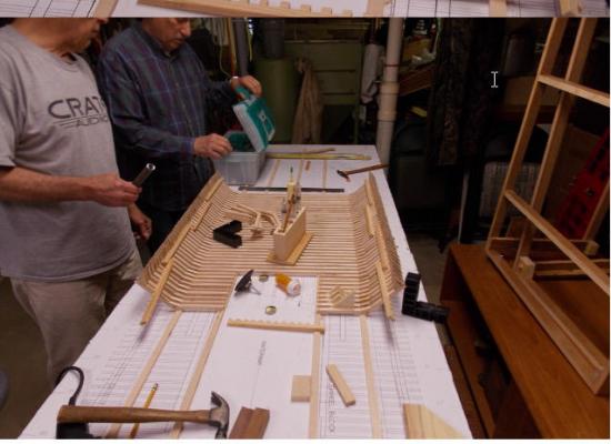
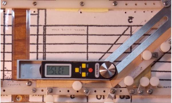
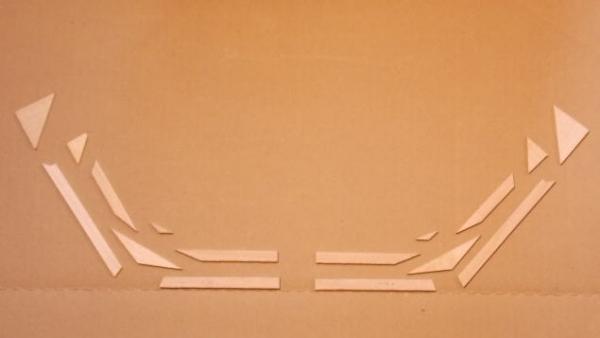
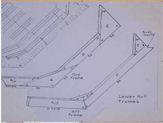
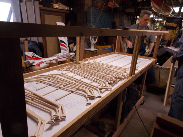
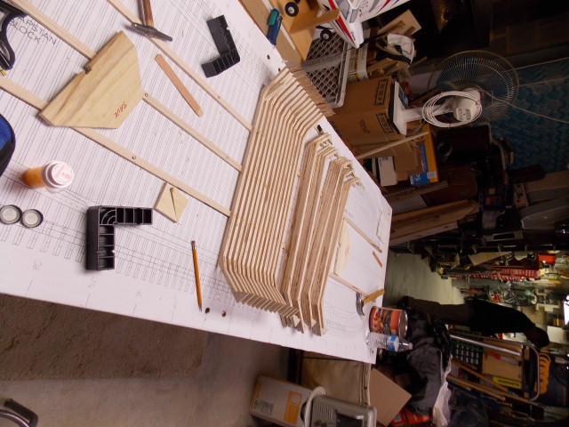
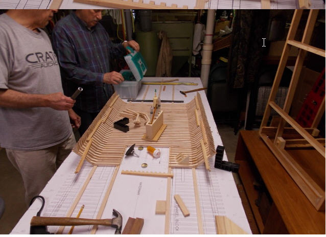
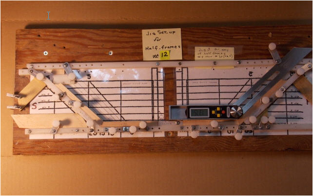
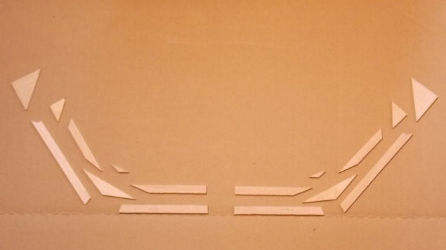
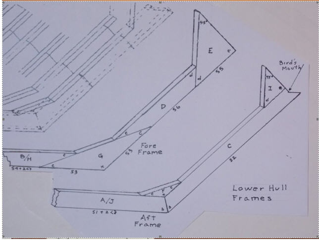
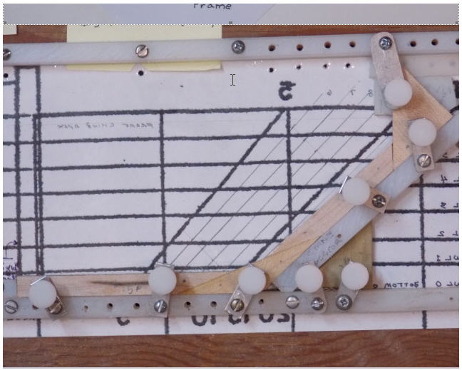
3. Fabricate all full and half frames up to the gun deck level chines using the three assembly jigs, locate them to the plans using small try-squares, and secure them to the keels with "Titebond III" wood glue and .052" diameter treenails in .055" holes. Place temporary wood support strips, which are the same thickness as the keels, under the lower frame floors at their outboard edges. (Do not glue or treenail the frames to these strips) Make a dozen or more wooden combs about 9" long by 1" wide by .25" thick which are dadoed to the "room and space" dimensions of the lower hull framing. Use these combs to temporarily locate and support the outboard ends of the frames as they are being secured to the keels. This is especially important for the aft half frames at the paddle wheel opening since they are only attached to one keel at this juncture. (By overlapping these 9" combs most of the hull structure can be made very rigid in preparation for installing the keelsons, deck clamps and other longitudinal structural members.)
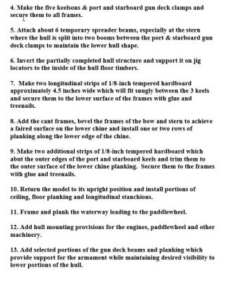
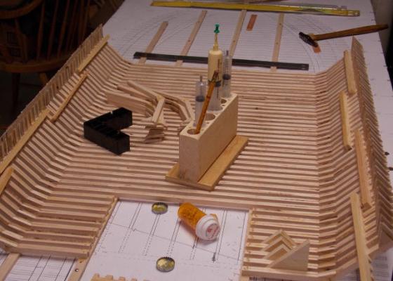
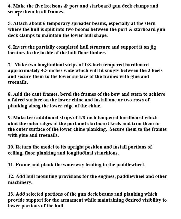
4. Make the five keelsons & port and starboard gun deck clamps and secure them to all frames.
5. Attach about 6 temporary spreader beams, especially at the stern where the hull is split into two booms between the port & starboard gun deck clamps to maintain the lower hull shape.
6. Invert the partially completed hull structure and support it on jig locators to the inside of the hull floor timbers.
7. Make two longitudinal strips of 1/8-inch tempered hardboard approximately 4.5 inches wide which will fit snugly between the 3 keels and secure them to the lower surface of the frames with glue and treenails.
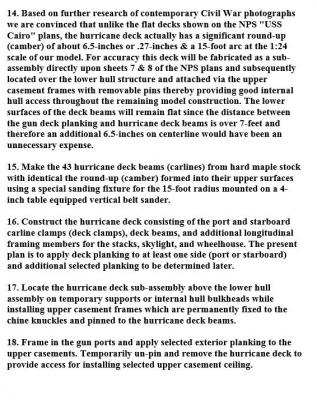
8. Add the cant frames, bevel the frames of the bow and stern to achieve a faired surface on the lower chine and install one or two rows of planking along the lower edge of the chine.
9. Make two additional strips of 1/8-inch tempered hardboard which abut the outer edges of the port and starboard keels and trim them to the outer surface of the lower chine planking. Secure them to the frames with glue and treenails.
10. Return the model to its upright position and install portions of ceiling, floor planking and longitudinal stanchions.
11. Frame and plank the waterway leading to the paddlewheel.
12. Add hull mounting provisions for the engines, paddlewheel and other machinery.
13. Add selected portions of the gun deck beams and planking which provide support for the armament while maintaining desired visibility to lower portions of the hull.
14. Based on further research of contemporary Civil War photographs we are convinced that unlike the flat decks shown on the NPS "USS Cairo" plans, the hurricane deck actually has a significant round-up (camber) of about 6.5-inches or .27-inches & a 15-foot arc at the 1:24 scale of our model. For accuracy this deck will be fabricated as a sub-assembly directly upon sheets 7 & 8 of the NPS plans and subsequently located over the lower hull structure and attached via the upper casement frames with removable pins thereby providing good internal hull access throughout the remaining model construction. The lower surfaces of the deck beams will remain flat since the distance between the gun deck planking and hurricane deck beams is over 7-feet and therefore an additional 6.5-inches on centerline would have been an unnecessary expense.
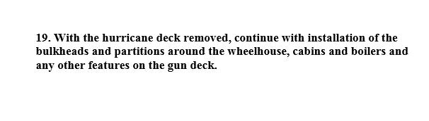
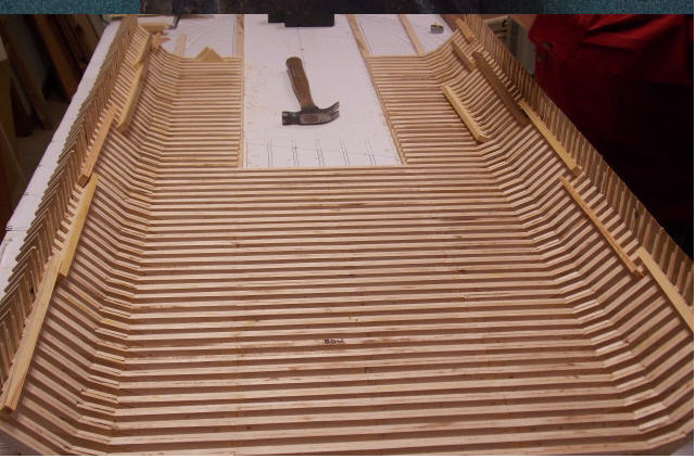
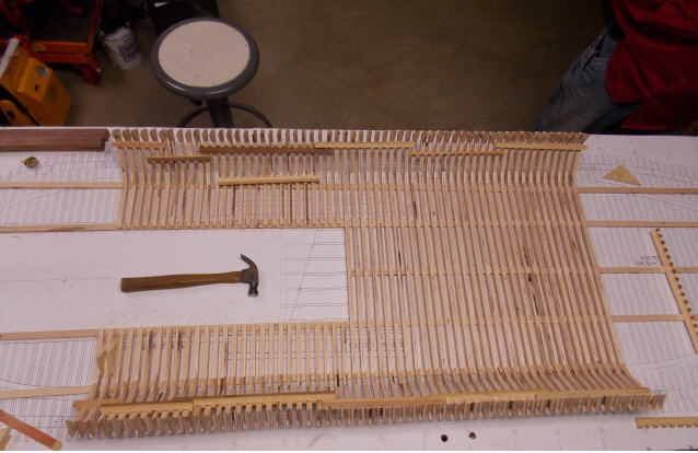
15. Make the 43 hurricane deck beams (carlines) from hard maple stock with identical the round-up (camber) formed into their upper surfaces using a special sanding fixture for the 15-foot radius mounted on a 4-inch table equipped vertical belt sander.
16. Construct the hurricane deck consisting of the port and starboard carline clamps (deck clamps), deck beams, and additional longitudinal framing members for the stacks, skylight, and wheelhouse. The present plan is to apply deck planking to at least one side (port or starboard) and additional selected planking to be determined later.
17. Locate the hurricane deck sub-assembly above the lower hull assembly on temporary supports or internal hull bulkheads while installing upper casement frames which are permanently fixed to the chine knuckles and pinned to the hurricane deck beams.
18. Frame in the gun ports and apply selected exterior planking to the upper casements. Temporarily un-pin and remove the hurricane deck to provide access for installing selected upper casement ceiling.
19. With the hurricane deck removed, continue with installation of the bulkheads and partitions around the wheelhouse, cabins and boilers and any other features on the gun deck.
Method used to Construct the Lower Hull Frames (Rev A).doc
Snap26.bmp
Snap27.bmp
Snap28.bmp
Snap29.bmp
Jig #3 Set-Up and Procedure for Use 26 Mar 2015.doc
Method used to Construct the Lower Hull Frames (Rev A).doc
Snap1.bmp
Snap2.bmp
Snap3.bmp
Snap5.bmp
Snap6.bmp
Snap7.bmp