Francesca
-
Posts
18 -
Joined
-
Last visited
Content Type
Profiles
Forums
Gallery
Events
Everything posted by Francesca
-
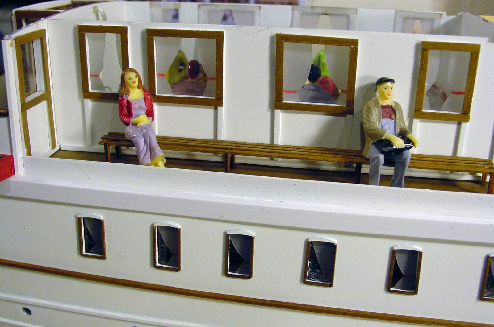
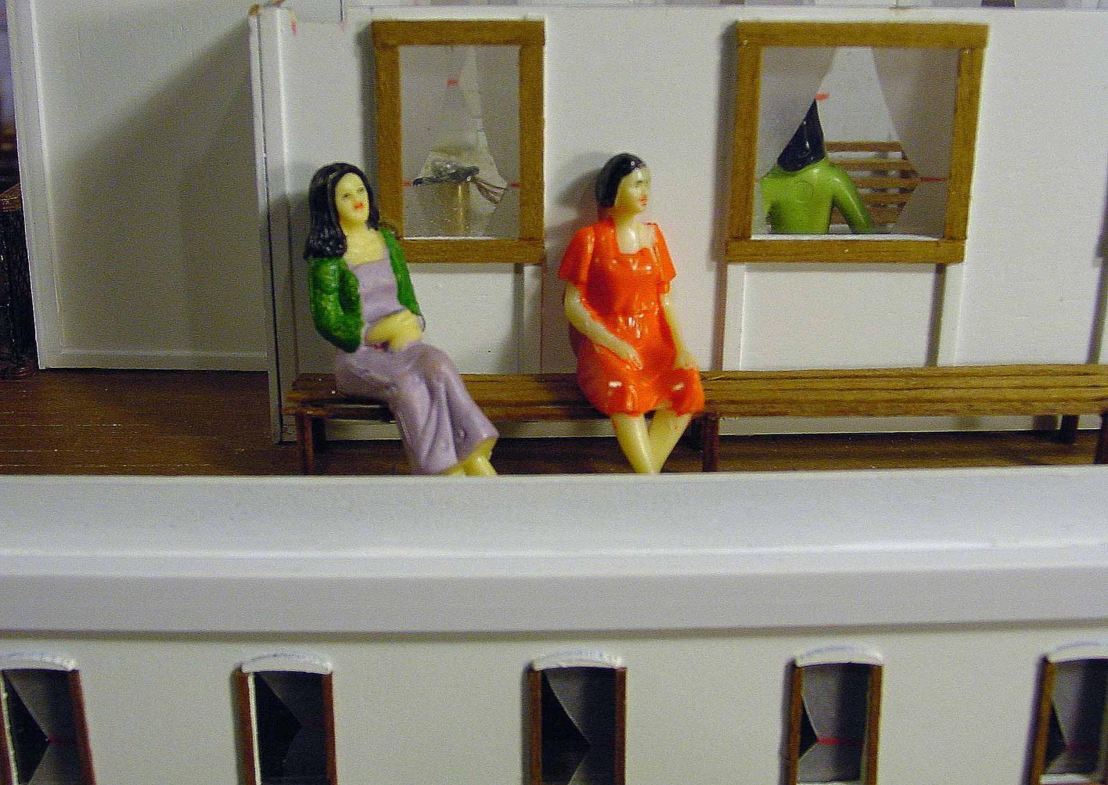
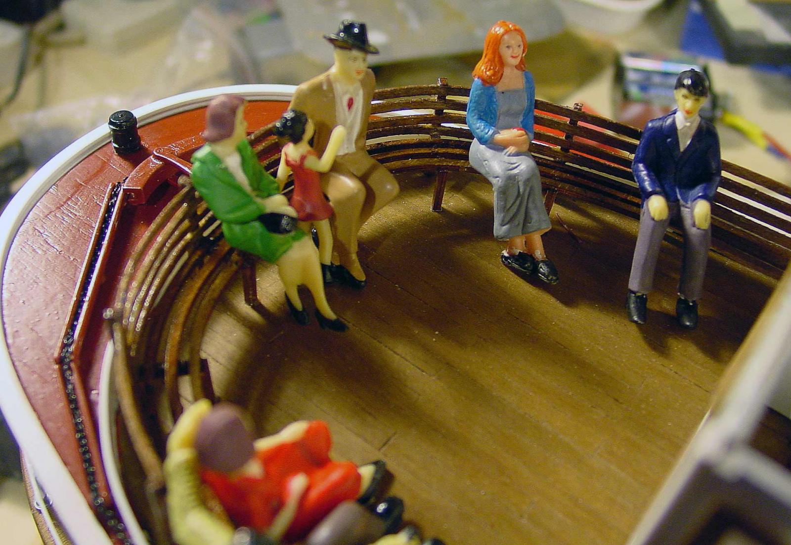
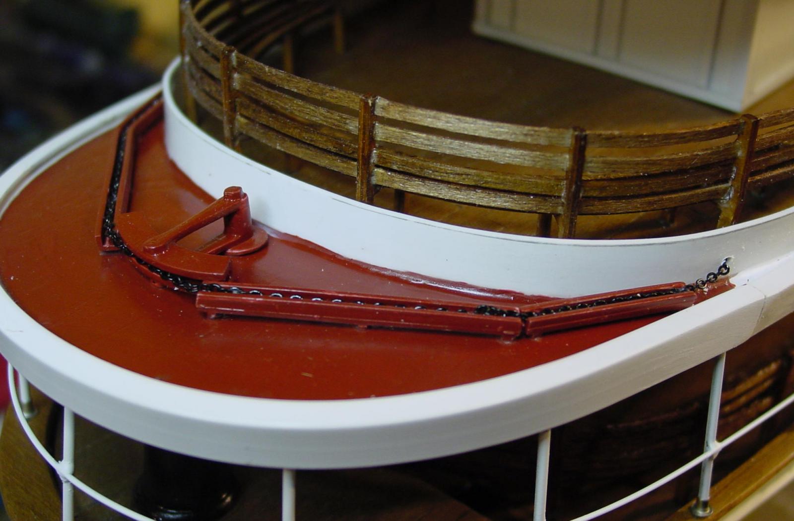
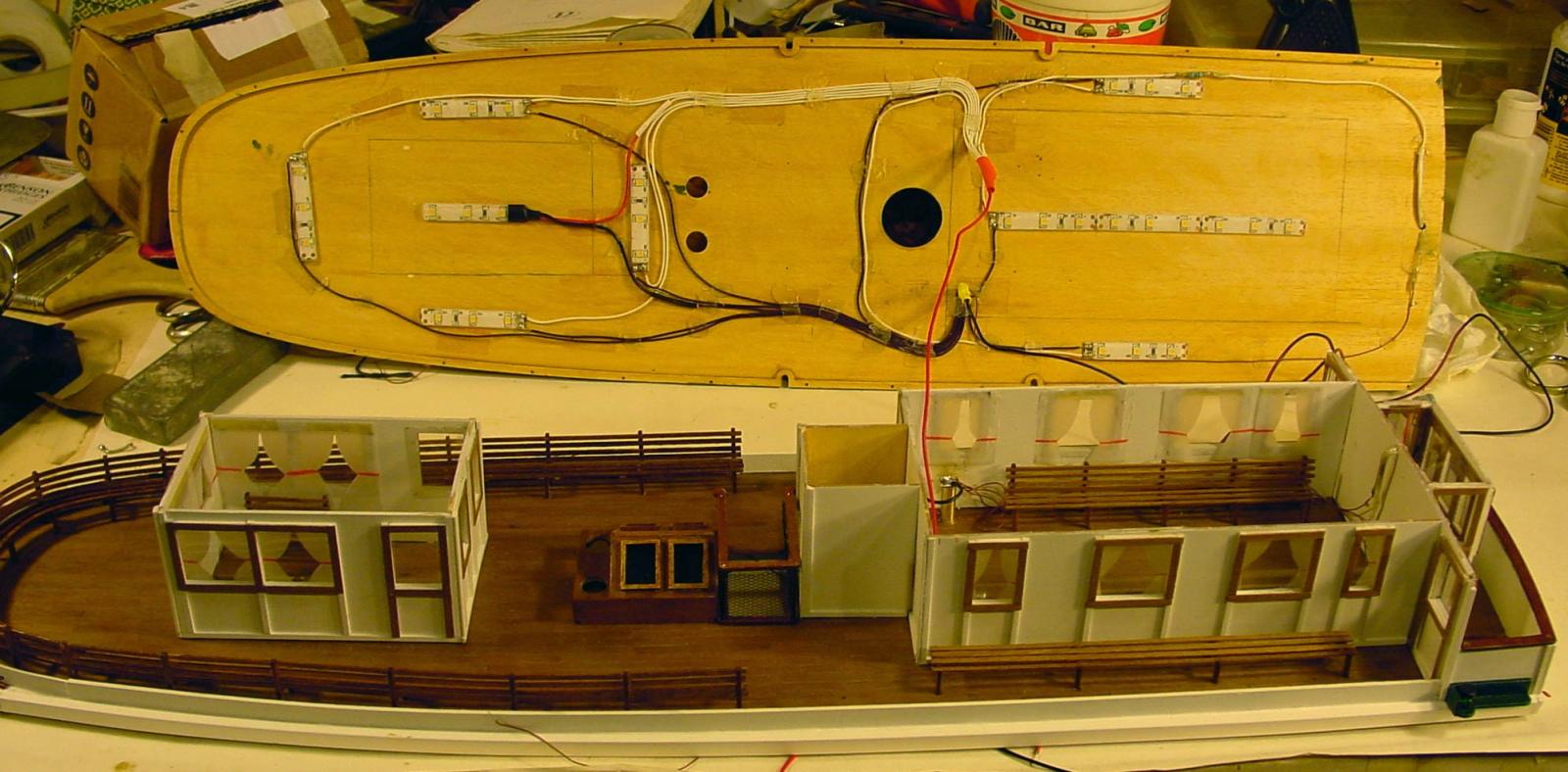
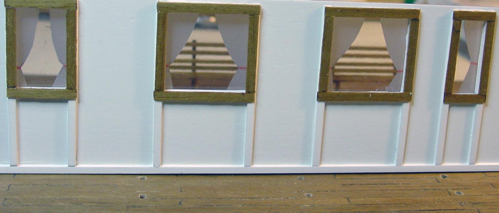
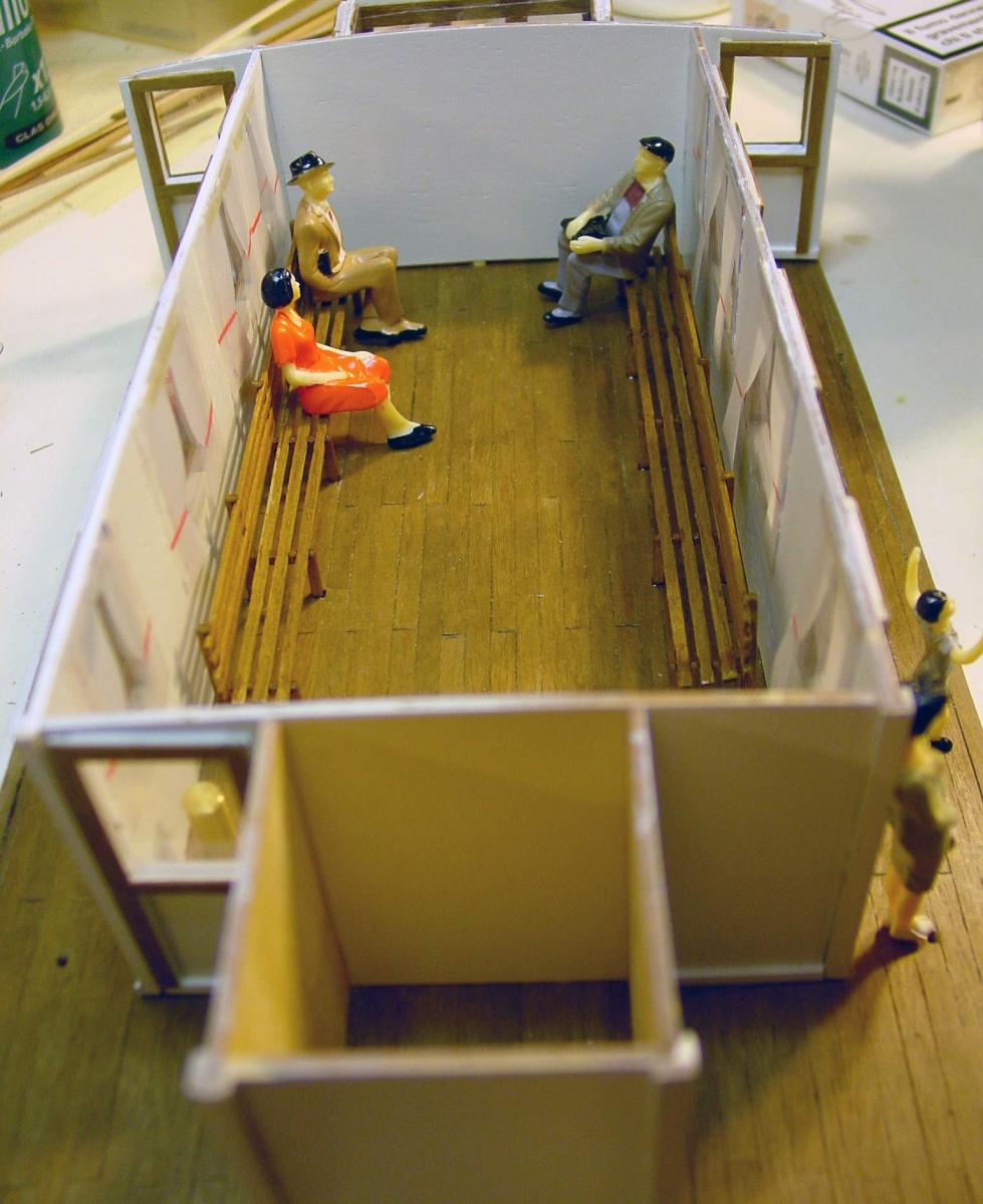
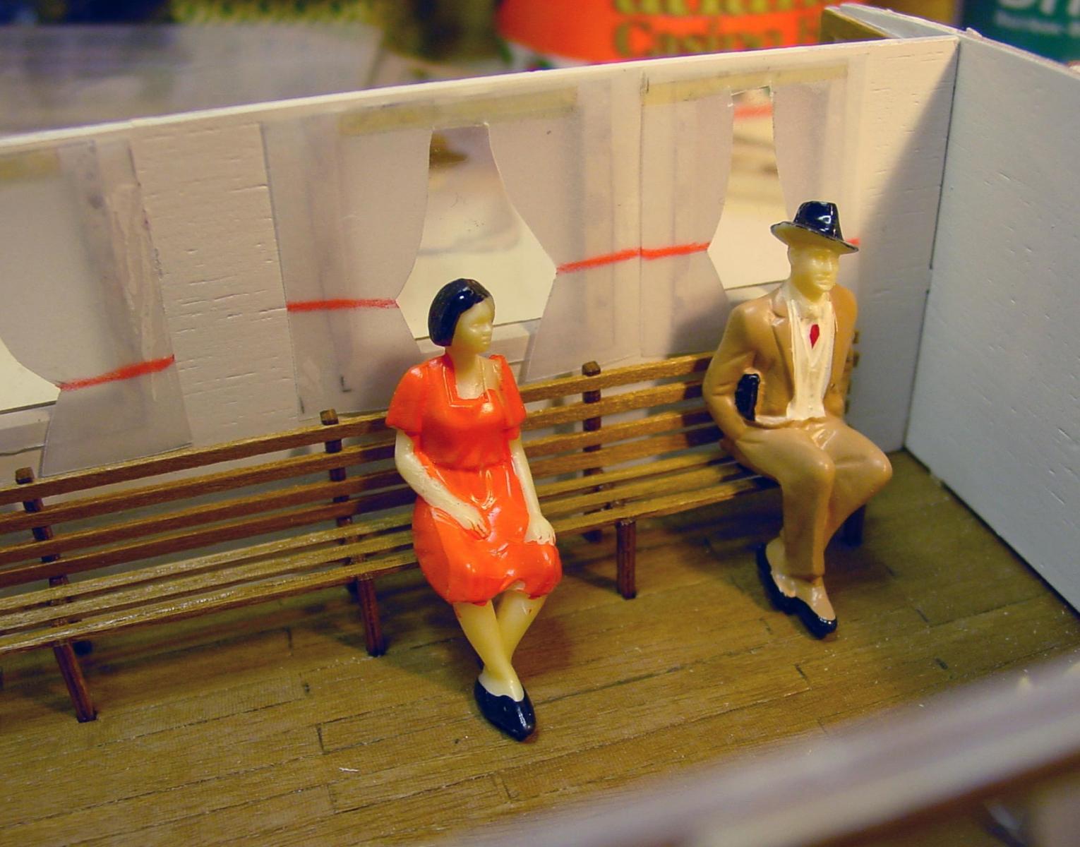
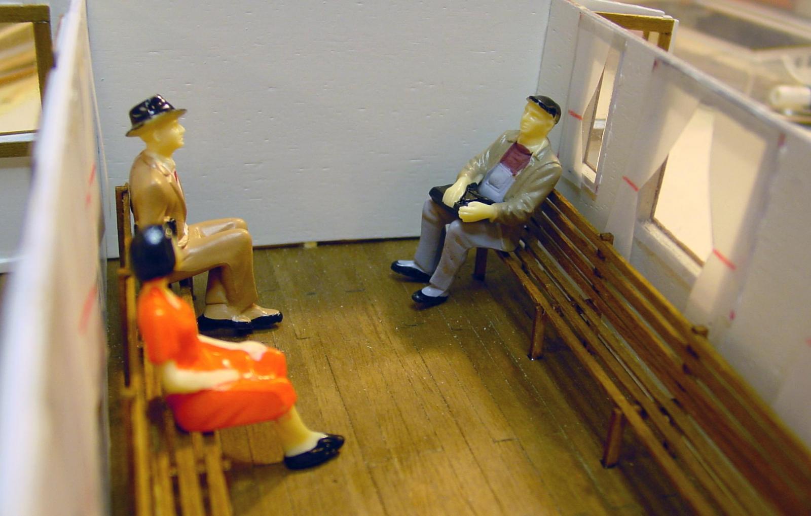
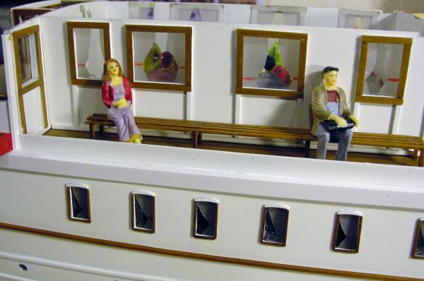
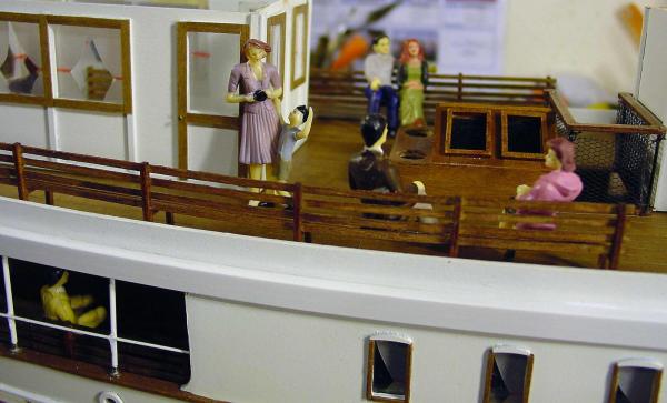
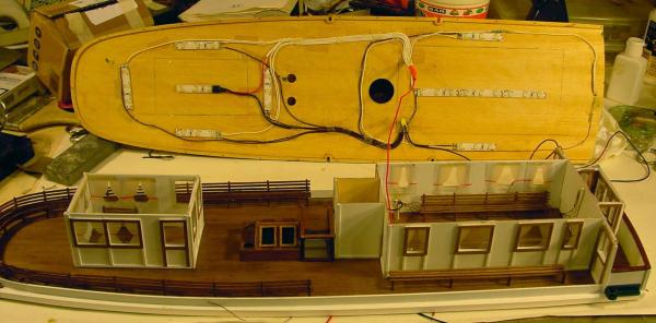
I forgot! After glued the glass in the windows (transparent acetate), I made curtains with opaque engineers paper. Then, on the upper deck and on the low deck, I added the passengers sitting on benches and standing. The rudder control mechanism (not working), the rudder will be operating below deck. Soon I will tell you something about the lighting with leds builded to have no cables and connectors between the hull and the removable upper deck. Bye Francesca


-
Thanks, Mark. Yes indeed, at pages 1 and 2 of this topic, you can see all Francesca
-
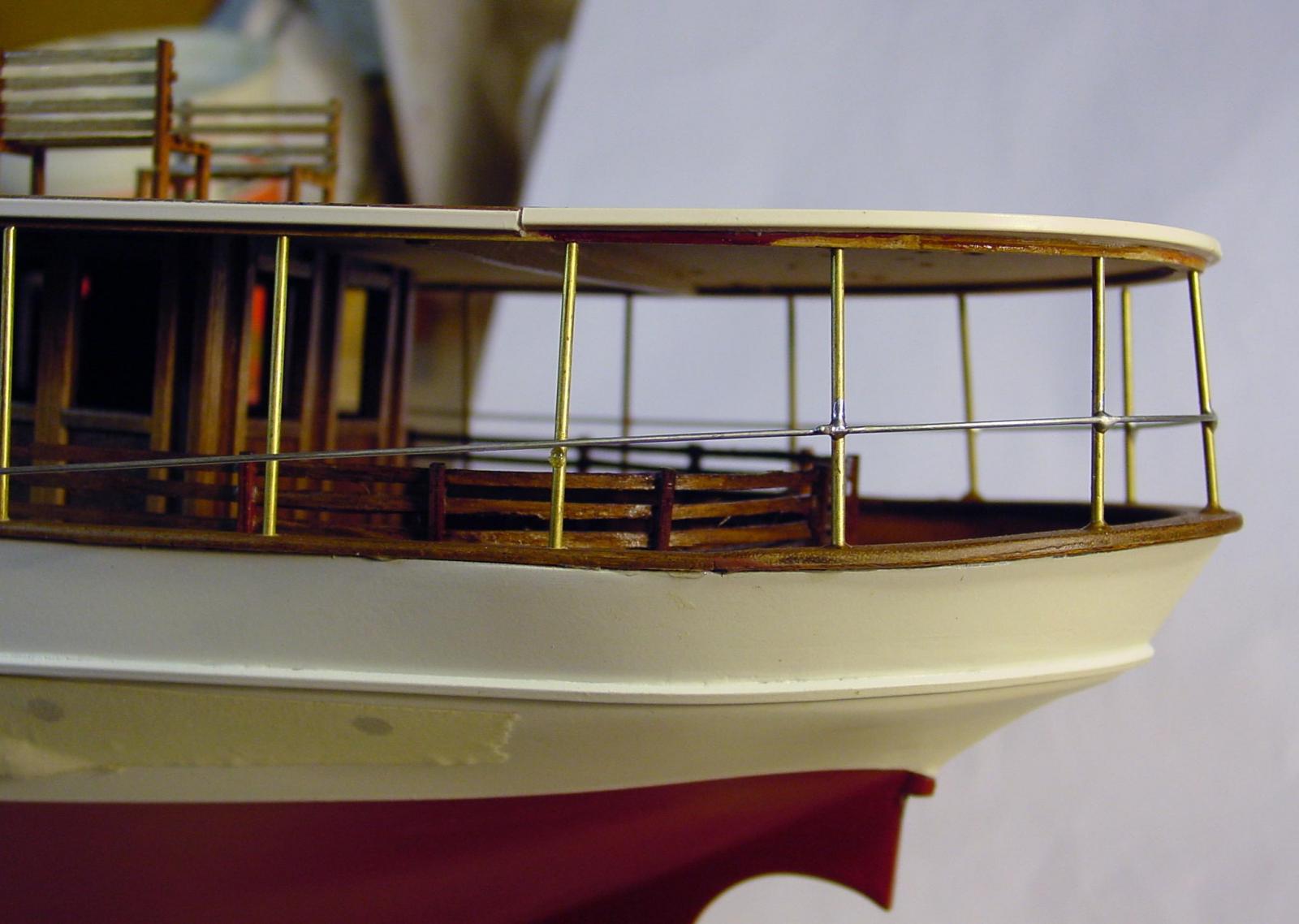
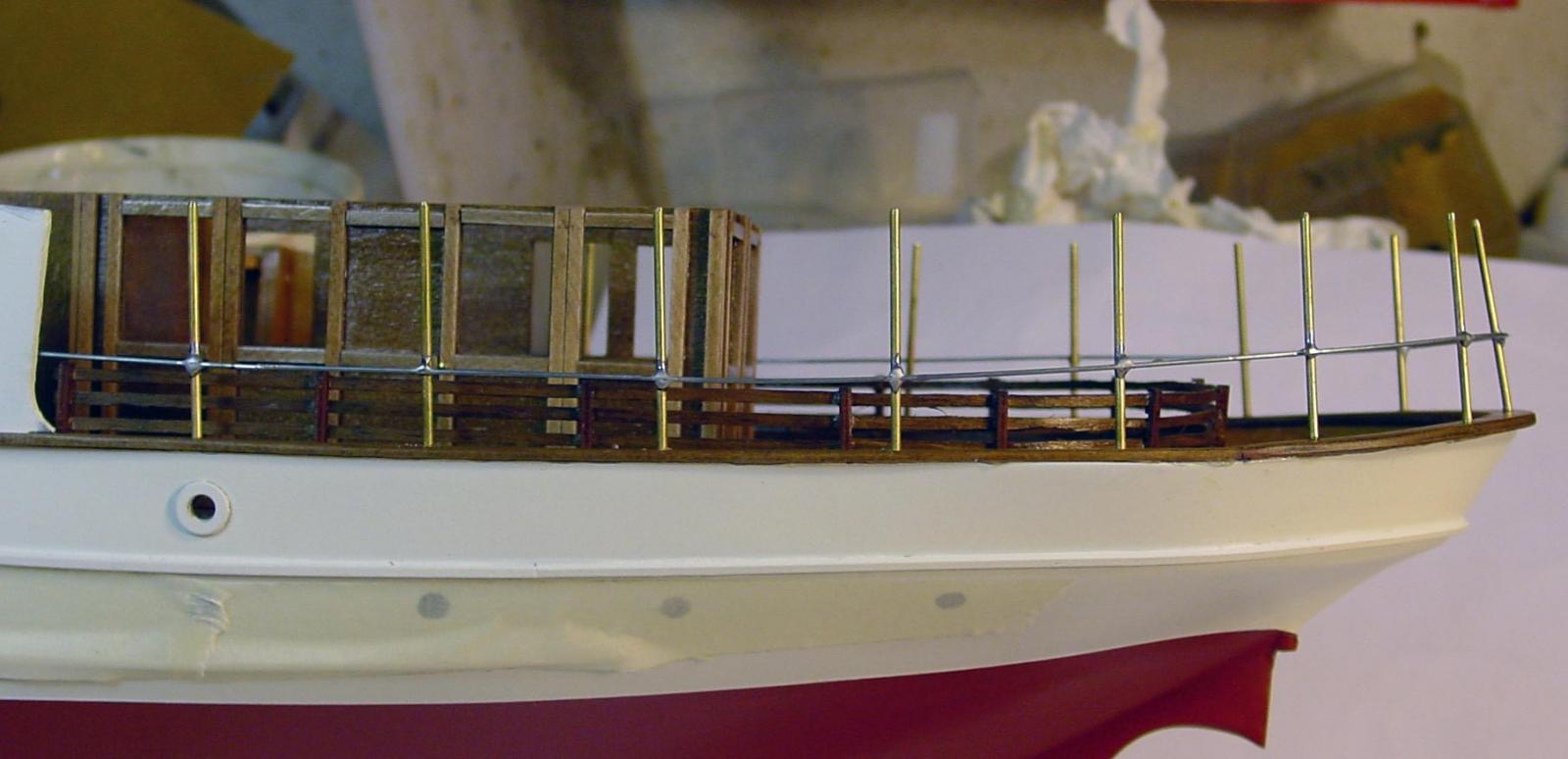
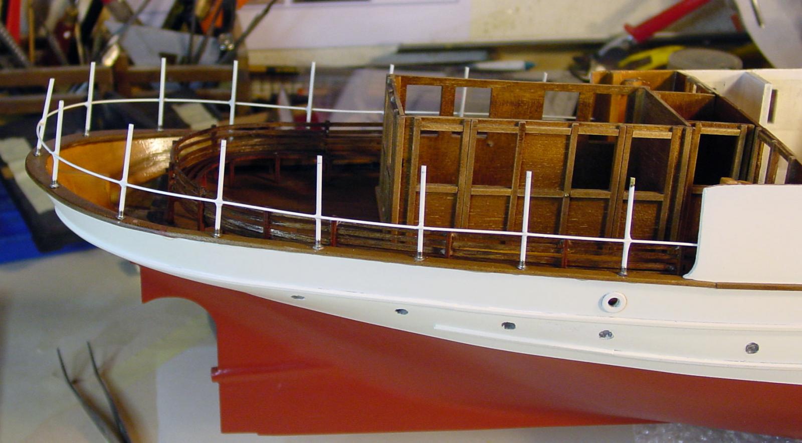
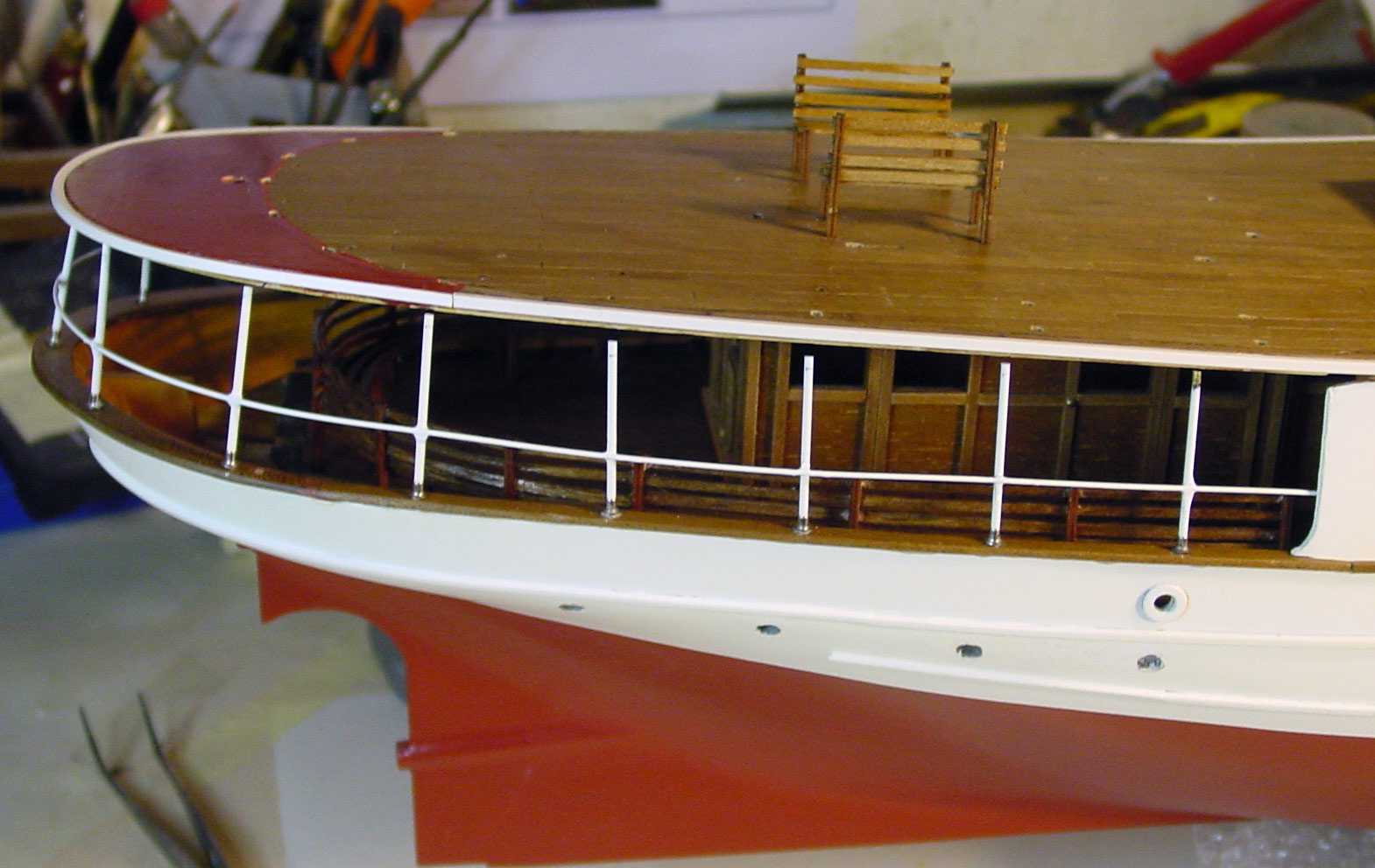
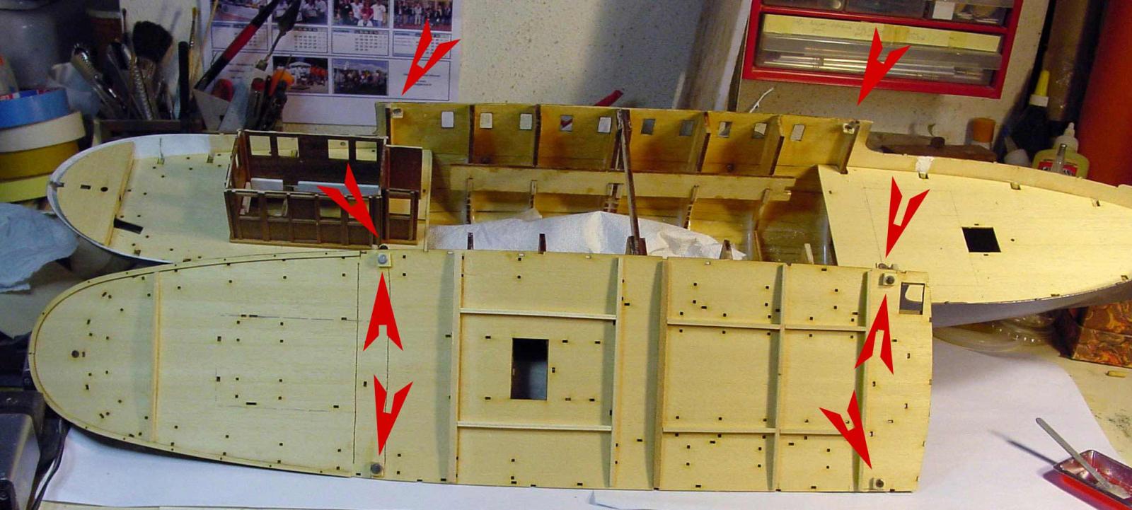
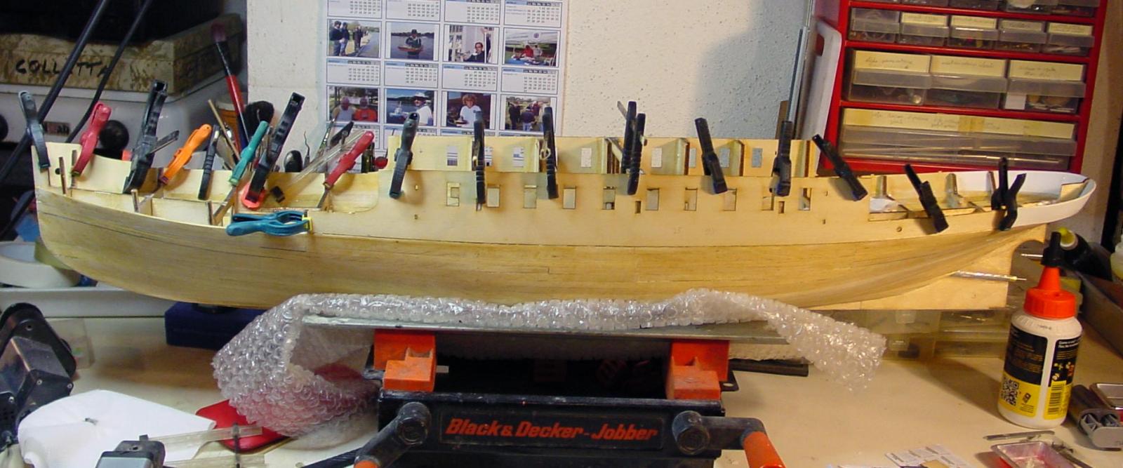
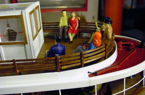
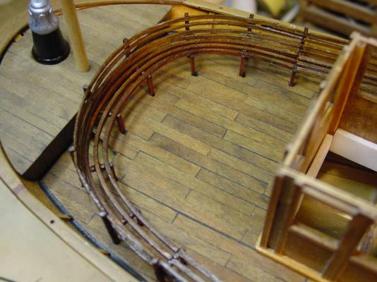
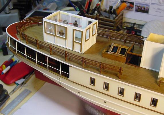
I'm here Sorry for silence, but I did very busy last times… Realization of stern benches Realization of metal uprights between the lower bridge and the upper, obtained with brass wire of 1.5 mm. on which I soldered the steel wire provided by the kit, all painted in matt white. The uprights are glued only on the lower side to permit removal of the upper part. Finally, I painted all in white matte spray. I, then, fix the guardrail bow: as mentioned above, provided by the candlesticks in white metal kits were truly horrendous and fragile, so I replaced them with others of the same size that I already had, in turned brass (when I can, I buy in low price inventory of accessories that can always serve ...); the wire passing from the kit supplied is 0.5 mm spring steel and I did not like because there was no way to straighten it: I replaced it with a 0.5 mm brass wire, straightened by pulling with forceps by a solid bench clamp. Candlesticks and thread were painted before laying, with spray white opaque. The whole was then glued into the holes with cyanoacrylate (superglue). Other picts... Lighting... We feel after the next post, thanks all you Realiz


-
Thanks very much, friends! But I would see also critical comments: it's very important for increase and improve
-
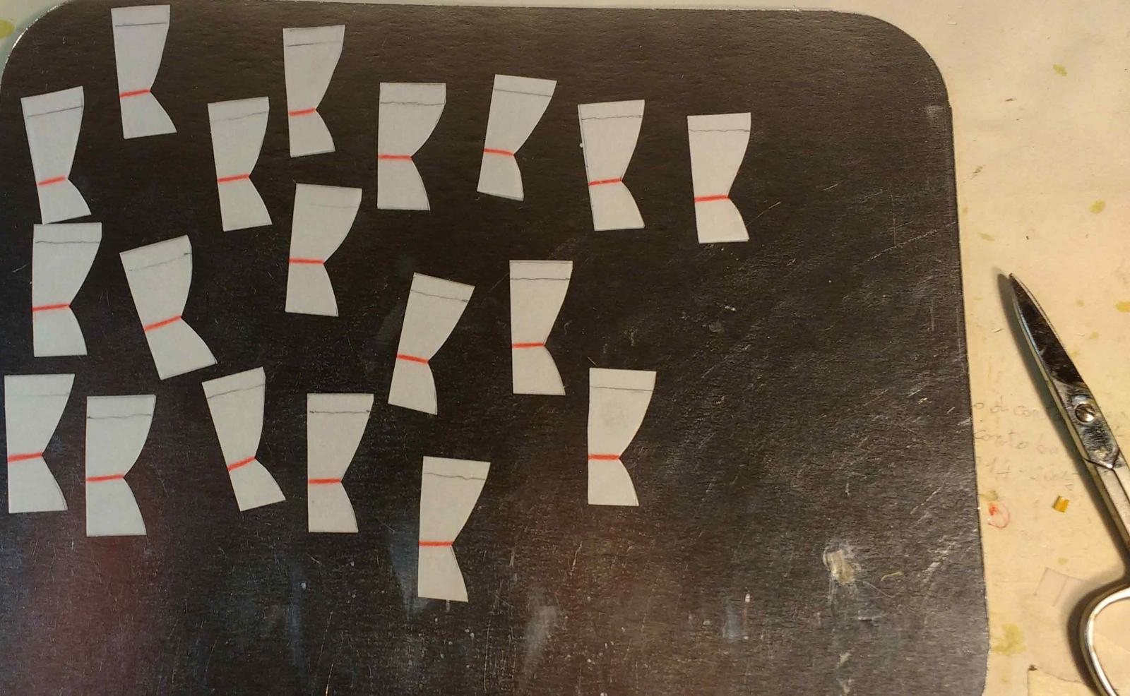
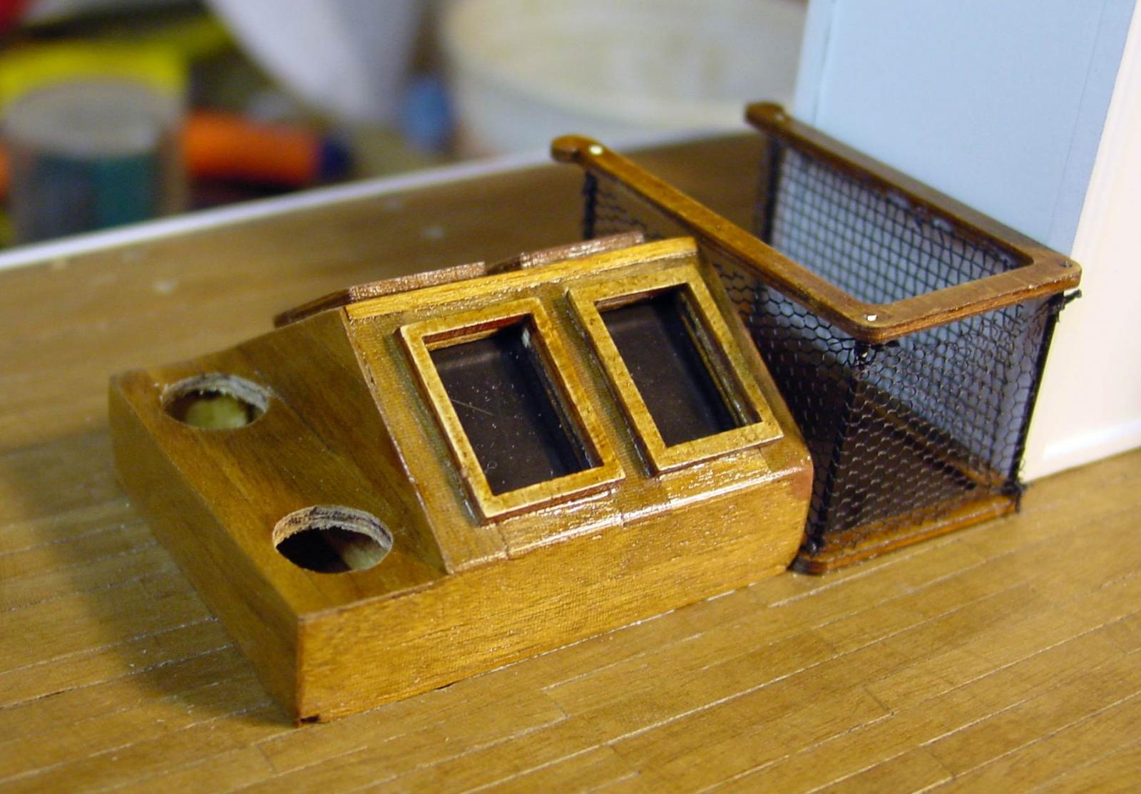
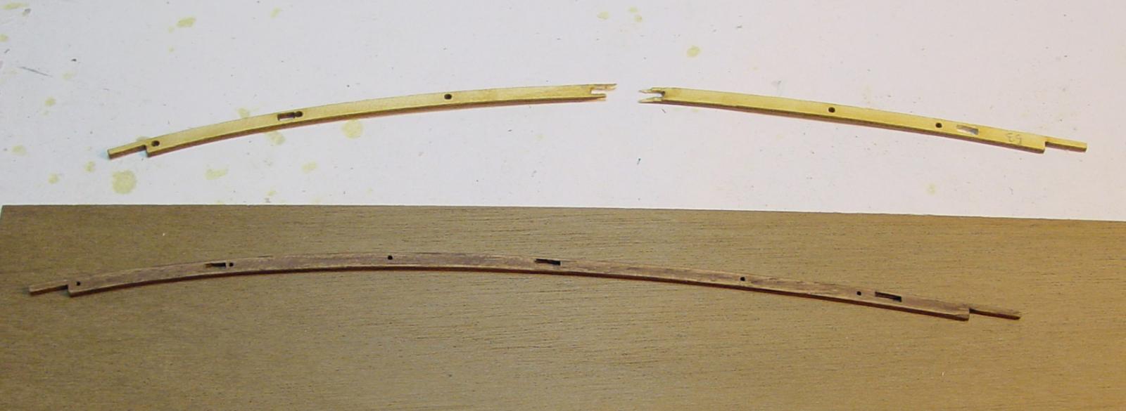
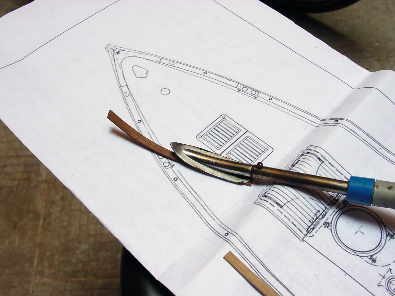
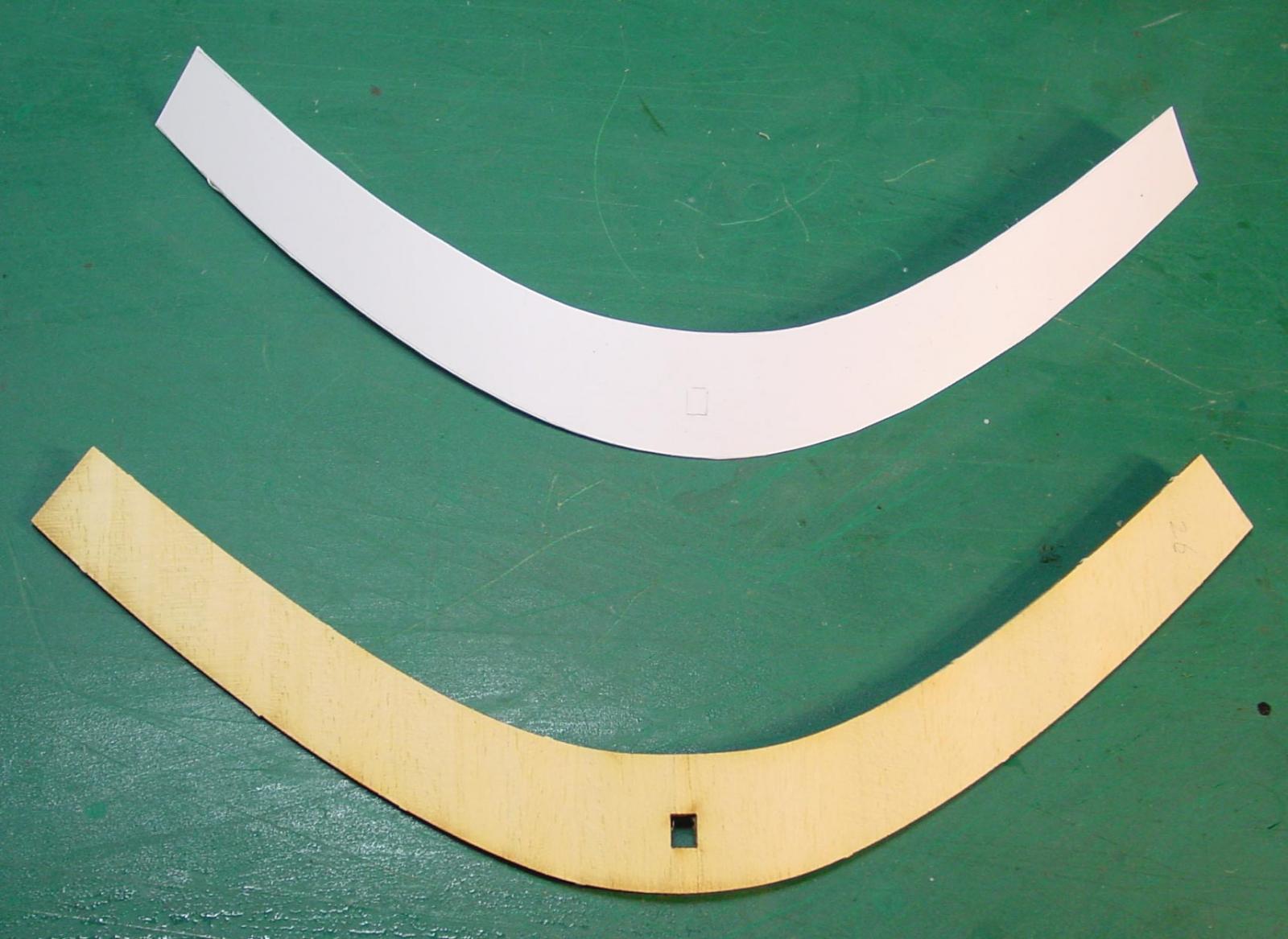
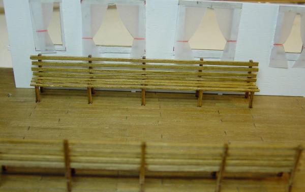
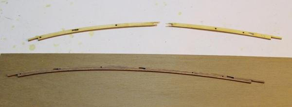
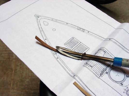
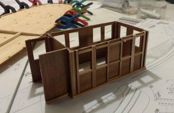
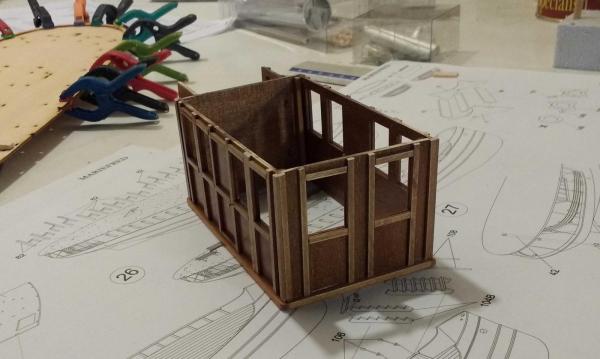
Hallo ! Finished the interior of the cabin with wooden benches, the glass in the windows with acetate, curtains with tracing paper and red pencil for finish. I tried people sitting inside (from China...). At this point I gave up, for now, the construction of the upper deck and started the construction of the lower deck. Shelves that overhang the sides: in the kit are pre-cut to laser plywood 1 mm., Also of rectangular holes which are used to fix them in place on the teeth that protrude from the sides. I do not like all that because the joints are seen . So, I reconstructed them with a walnut strip curved with a hot iron


-
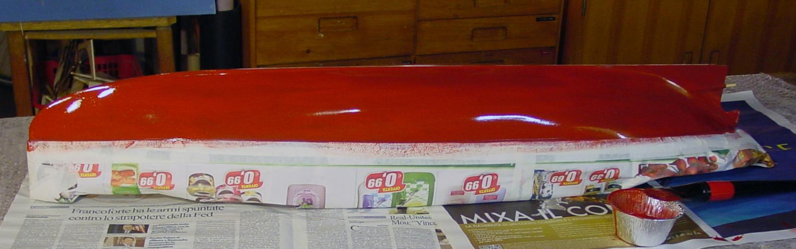
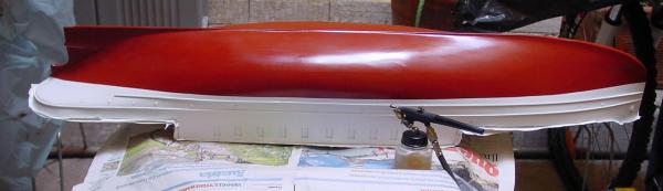
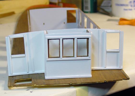
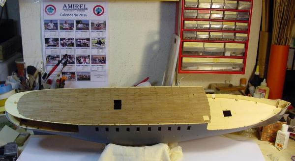
It 's time to paint the hull. After protecting the topsides and all over the top, including the bridge with tapes and newspapers, I gave a first-hand live on the work of red satin enamel rust, diluted with white spirit. Everything with brush. Then I finished the painting topsides white matt. At this point I noticed that the color of the hull had excessive disparity in appearance: the red satin was too shiny and opaque white was too opaque. So, to even out the whole painting, I decided to give transparent satin glaze on the whole with the airbrush. The painting of the hull is finished. Removed all the masking, finally the hull is in its final livery! While I waited for paint dries though, I indulged with the construction of the cabins on the upper deck. After applying all the strips around windows and doors I have given two coats of spray paint matt white.


-
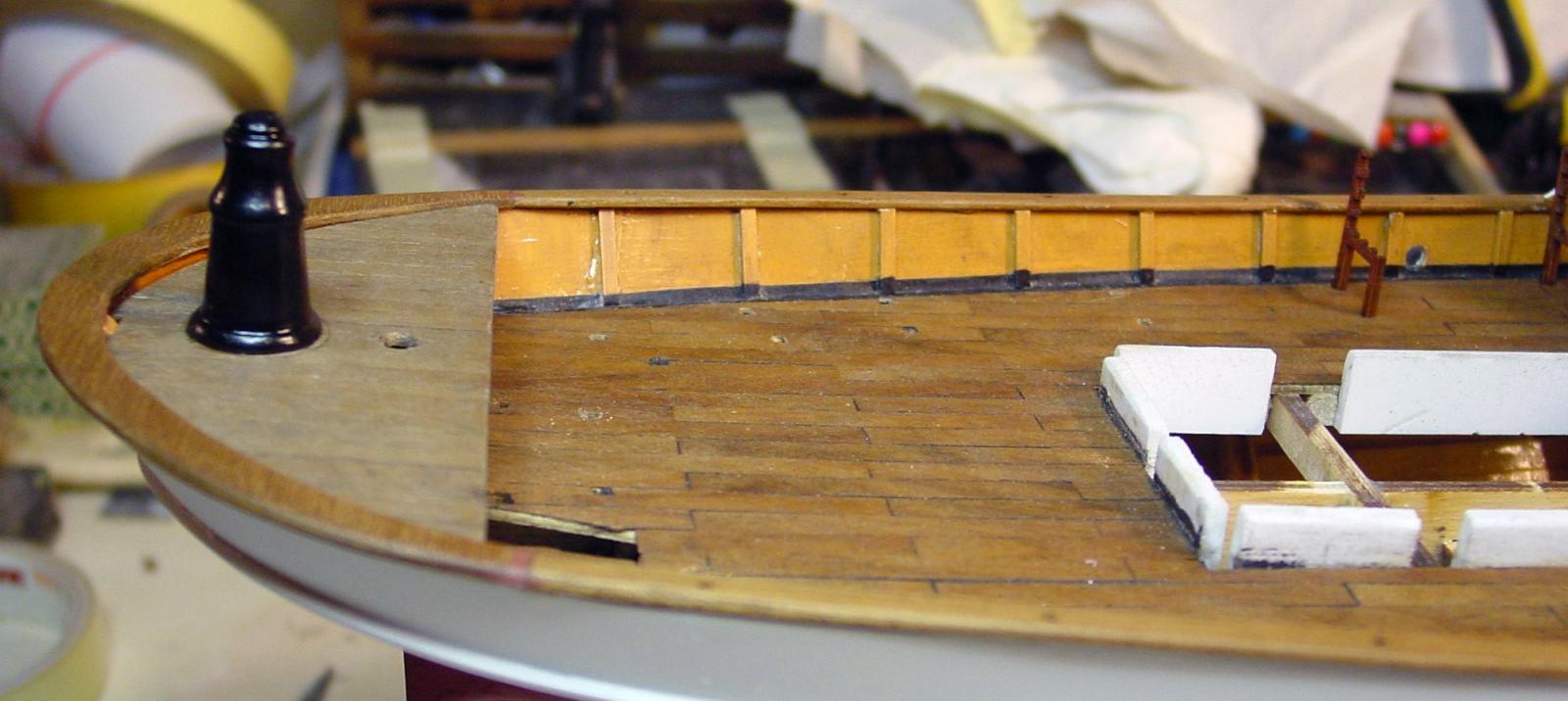
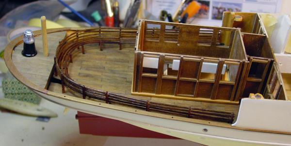
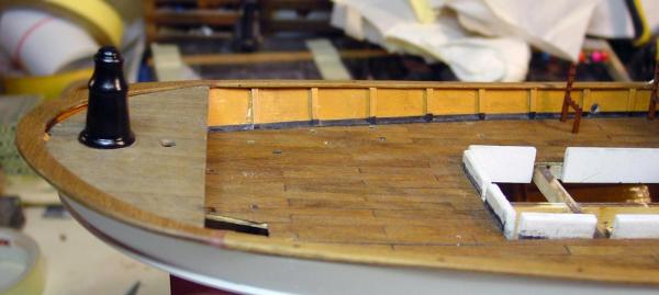
I go head in my bad english ,but I'm happy because I can see you understand. So, now I built the planks of the lower deck with walnut strips (not in the kit). First I painted the inside bulwarks, after finding a pict on the web. I covered all lower decks with walnut strips. All for today


-
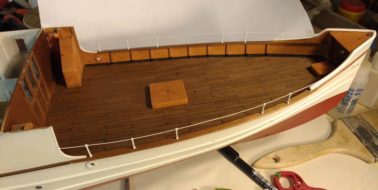
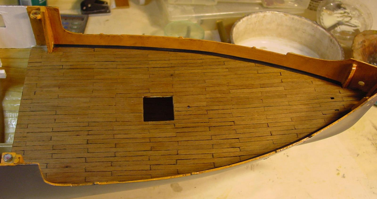
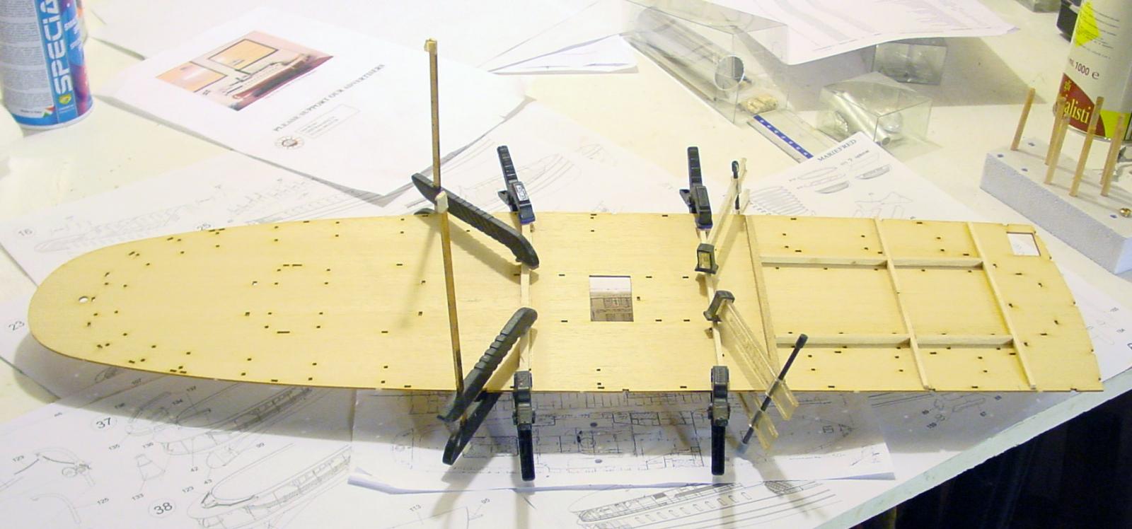
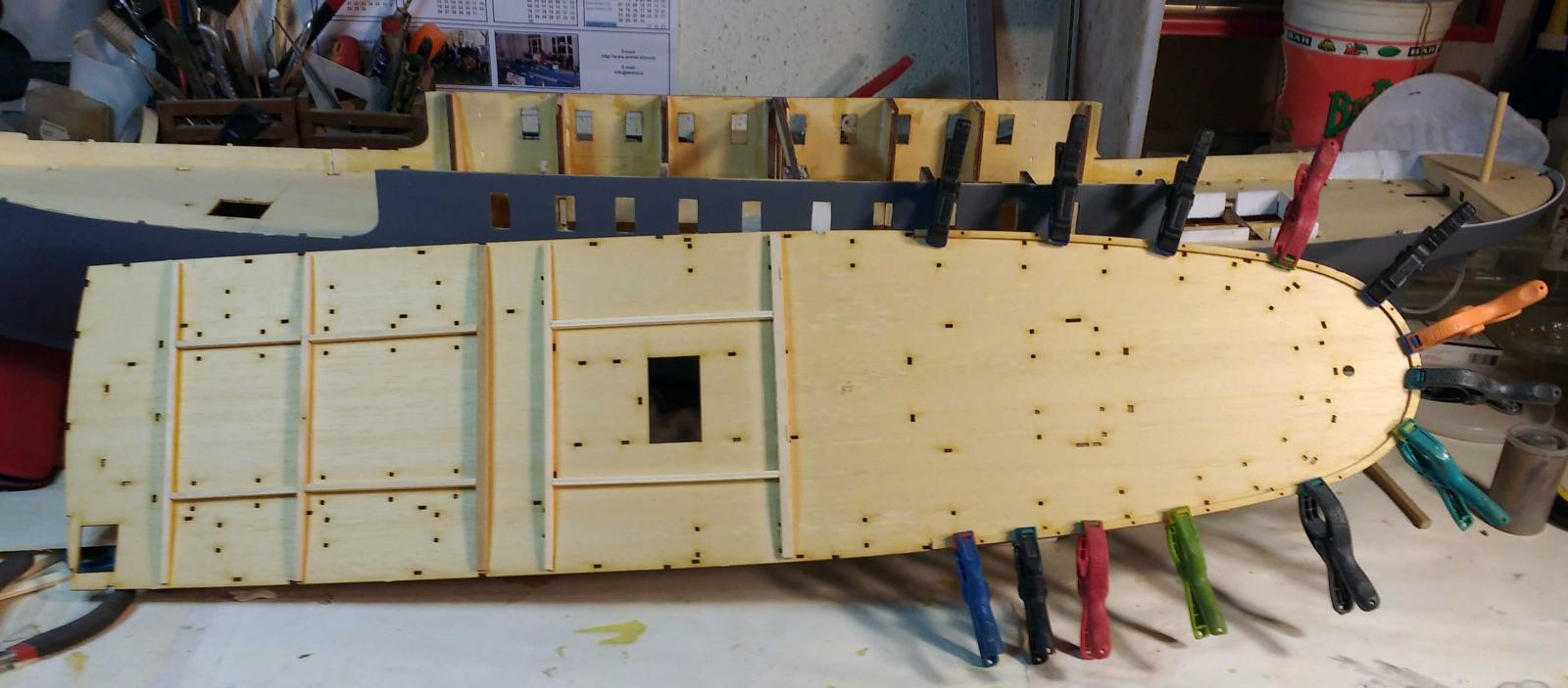
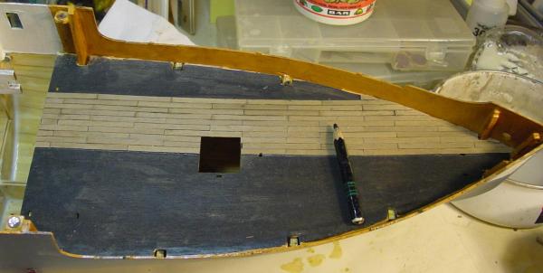
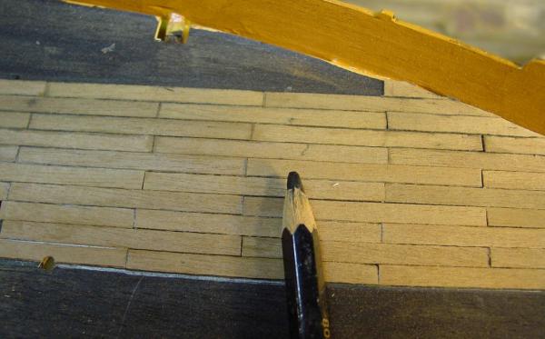
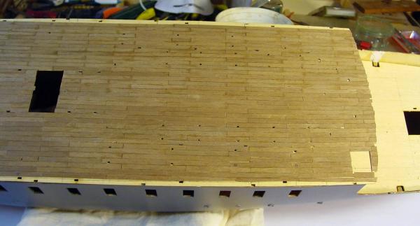
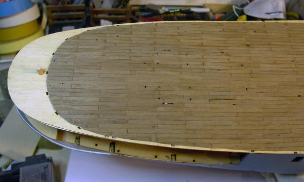
Now I started to think to the removable upper bridge. In the project, all is glued. It would be easy! Since all must be adapted to the underlying profiles, slightly curved, I began to realize ribs and spars to make it all fit and strong. I built the aft cabin on the lower deck Because this bridge must be easily removable, I installed an glued with epoxy resin eight neodymium magnets. After I covered the upper bridge with walnut strips wide 4 mm., 5 cm long. thickness 0.5 mm., alternating with half of each course and glued with quick vynil glue. I will stop for now


-
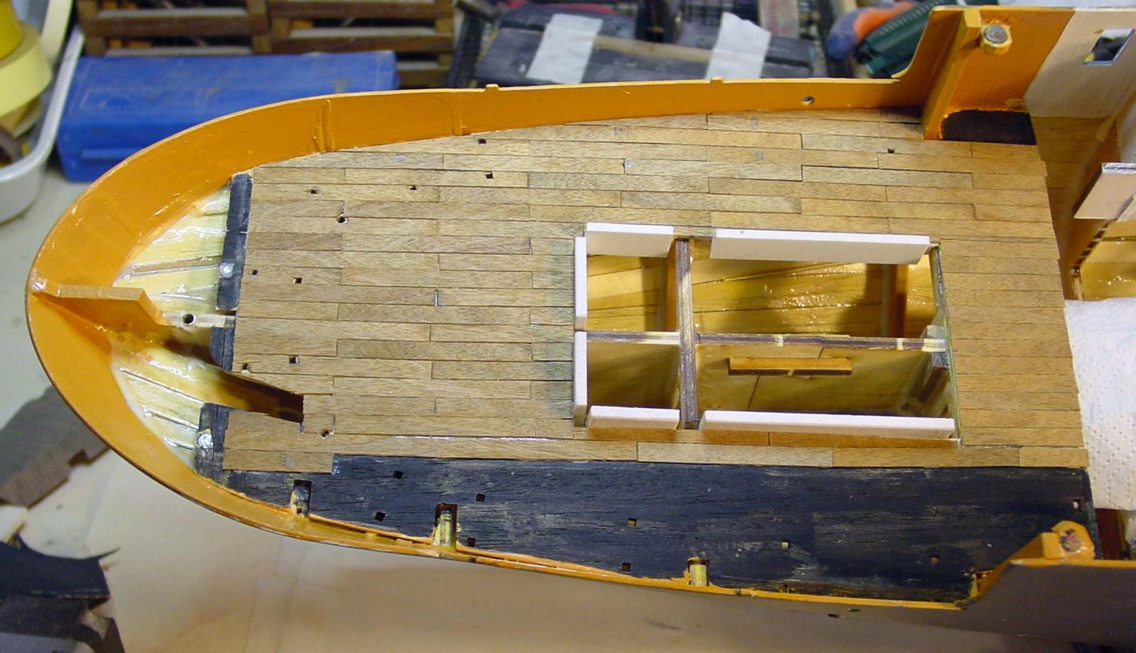
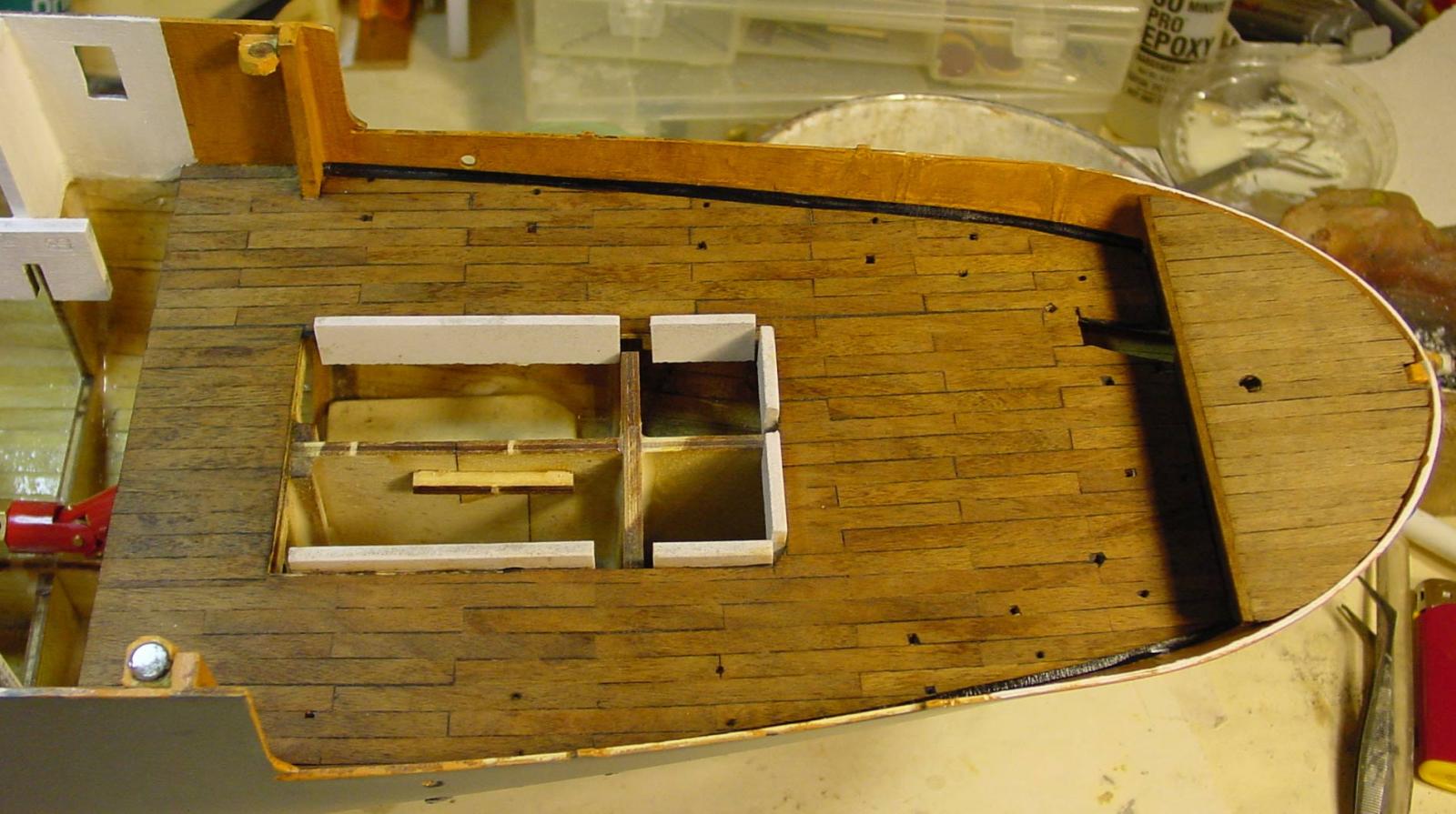
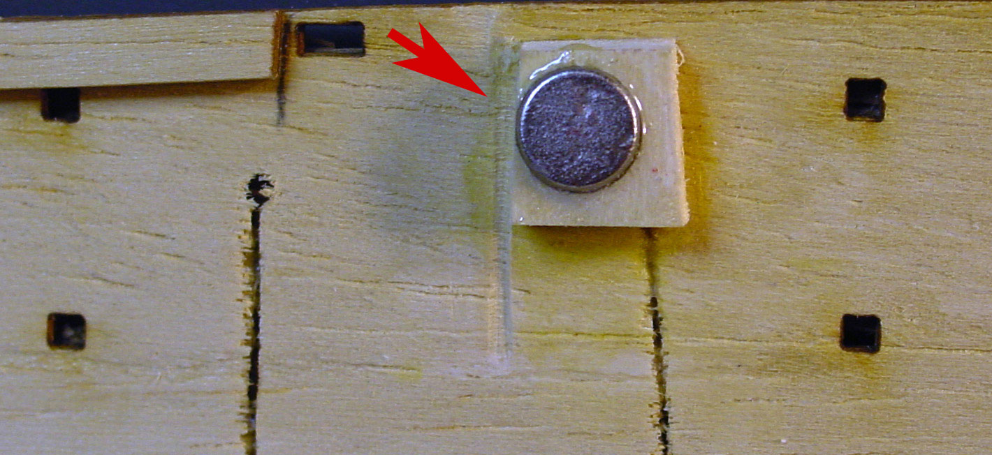
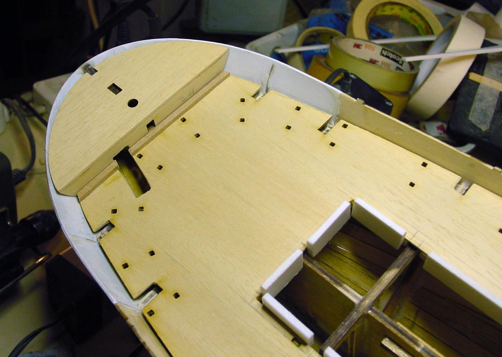
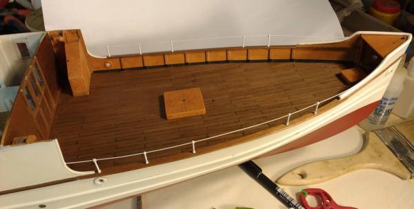
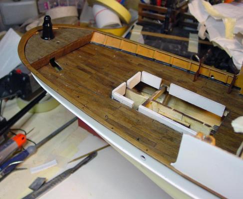
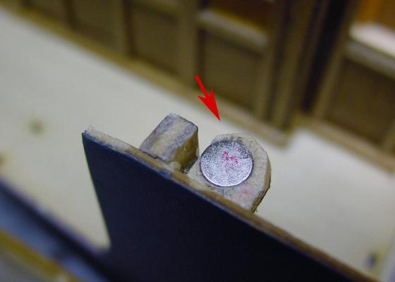
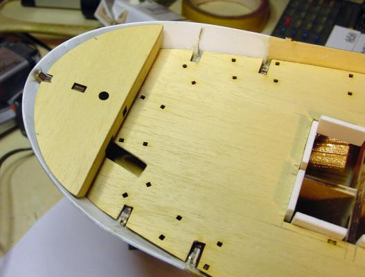
I decided to proceed with the lower deck previously prepared. I had already arranged on the deck, not only the cabin access , but also the opening for access to the rudder horn. On the deck, near the rudder horn, there is an upside that in the original project must be glued. Obviously I don't glued, because the compartment must be inspected. So I inserted neodymium chinese magnets very powerful but microscopic (6mm dia. X 2 mm. thick) to easily open and close this compartment. At this point, check the openings, confirming that everything fits well, I glued the aft deck. Ciao for today

-
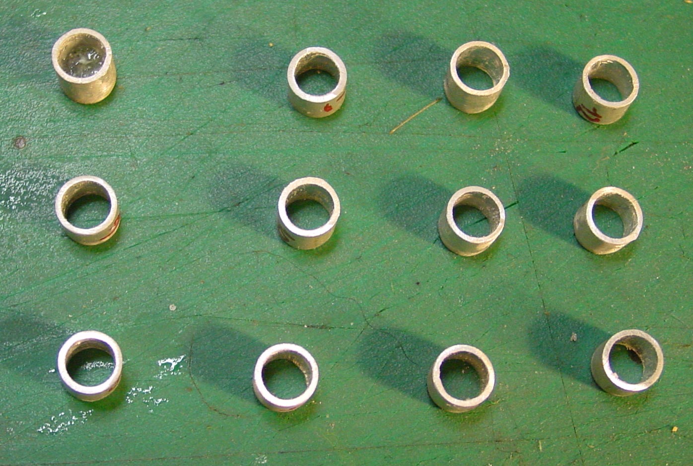
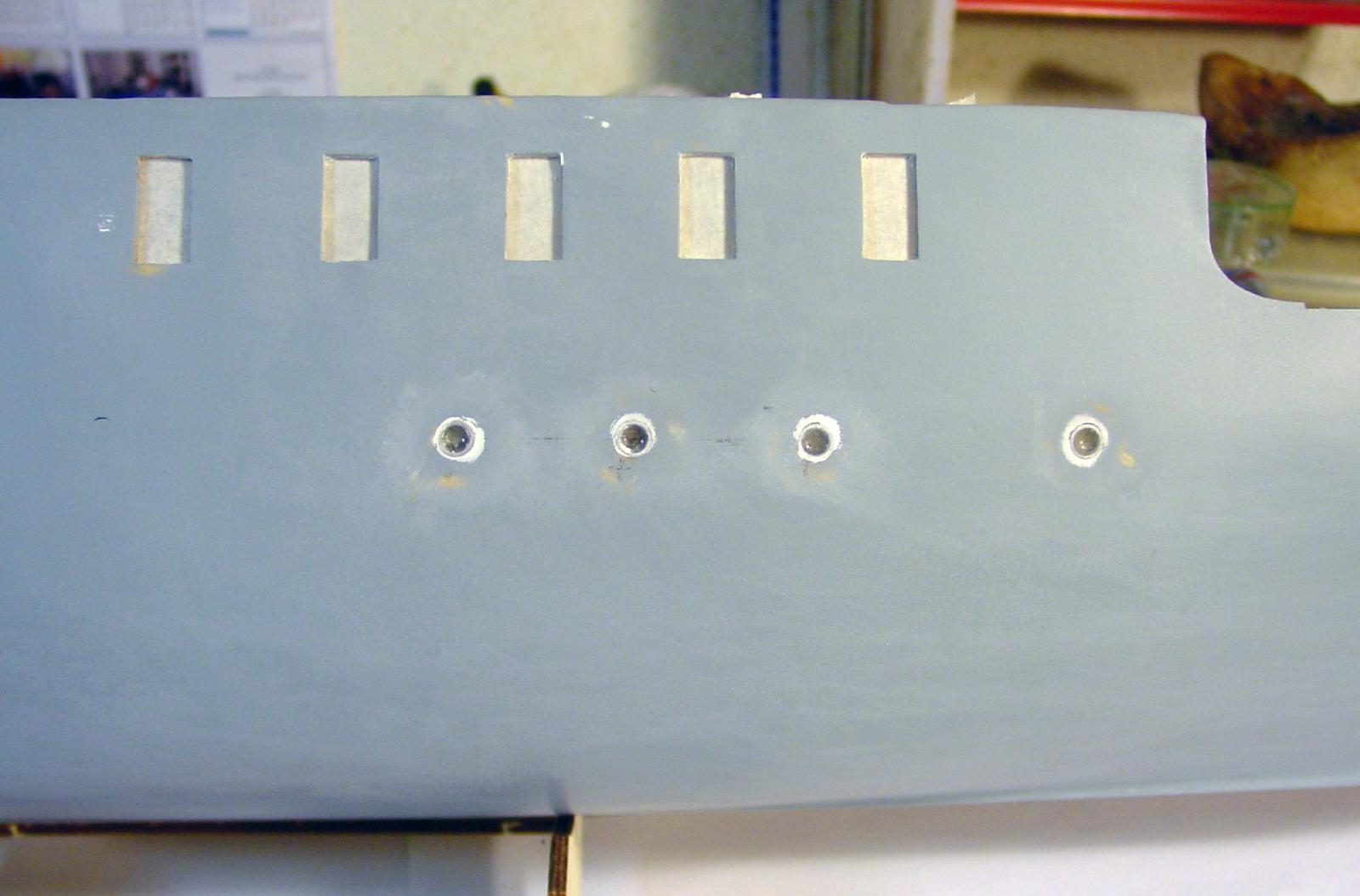
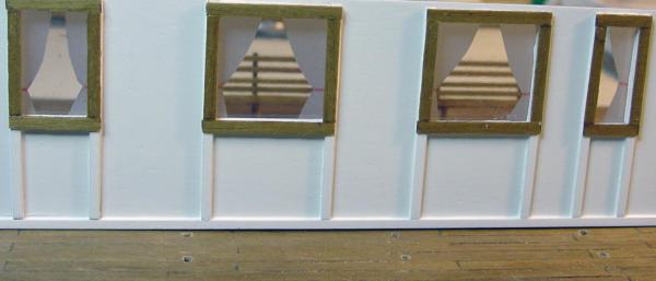
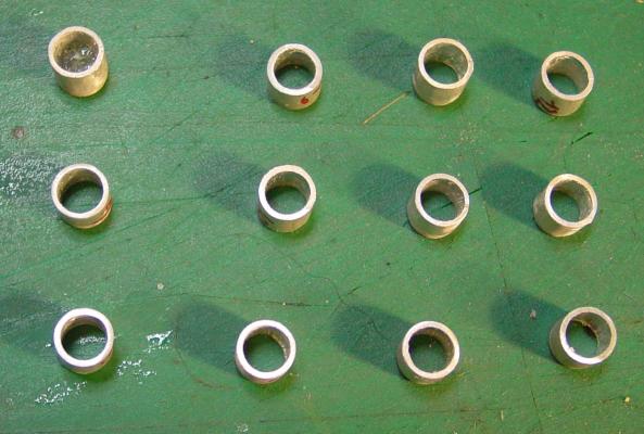
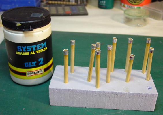
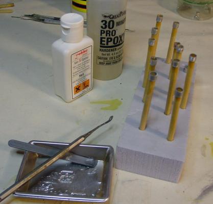
I go ahead quickly because I started this model several months ago and are far ahead in building. At this point I realize the portholes before gluing the bridges because they are below deck. From the photos finded on the web, I saw that the portholes are flangeless, wide side. From a aluminon tube diam. external 6 mm. I cut 24 slices 5mm., filed and clean with limes and fine emery paper, try in their holes. The depth of 5 mm., Greater than the thickness of the plating, I need to handle them better, once inserted under the bridge, the greater thickness is not seen. Now is the time to make the glass portholes: I cut 12 pieces of wooden rod with a diameter equal to the inner diameter of the portholes and prepared suitable holes in a piece of foam, surplus of previous work (but would be fine also a piece of wood or of any material not tough and easy to be drilled). This it will serve as the support for the rods of wood which, in turn, will support section to hold vertically the portholes. I smeared on the well-polished wooden rods Teflon grease (okay, however, any type of fat) and tucked portholes. After that, the tip of the portholes I filled with epoxy resin and, subsequently, pulled a little 'back the rods of wood, so that the resin is lowered, forming a slide convex. This will serve me then, during the coating phase, to tuck it in a ball of paper or other material to protect it from paint. When the resin has polymerized almost, I extracted with ease rods of wood and ... voila! Portholes with their slides transparent wire side are ready to be inserted and glued in place.

-
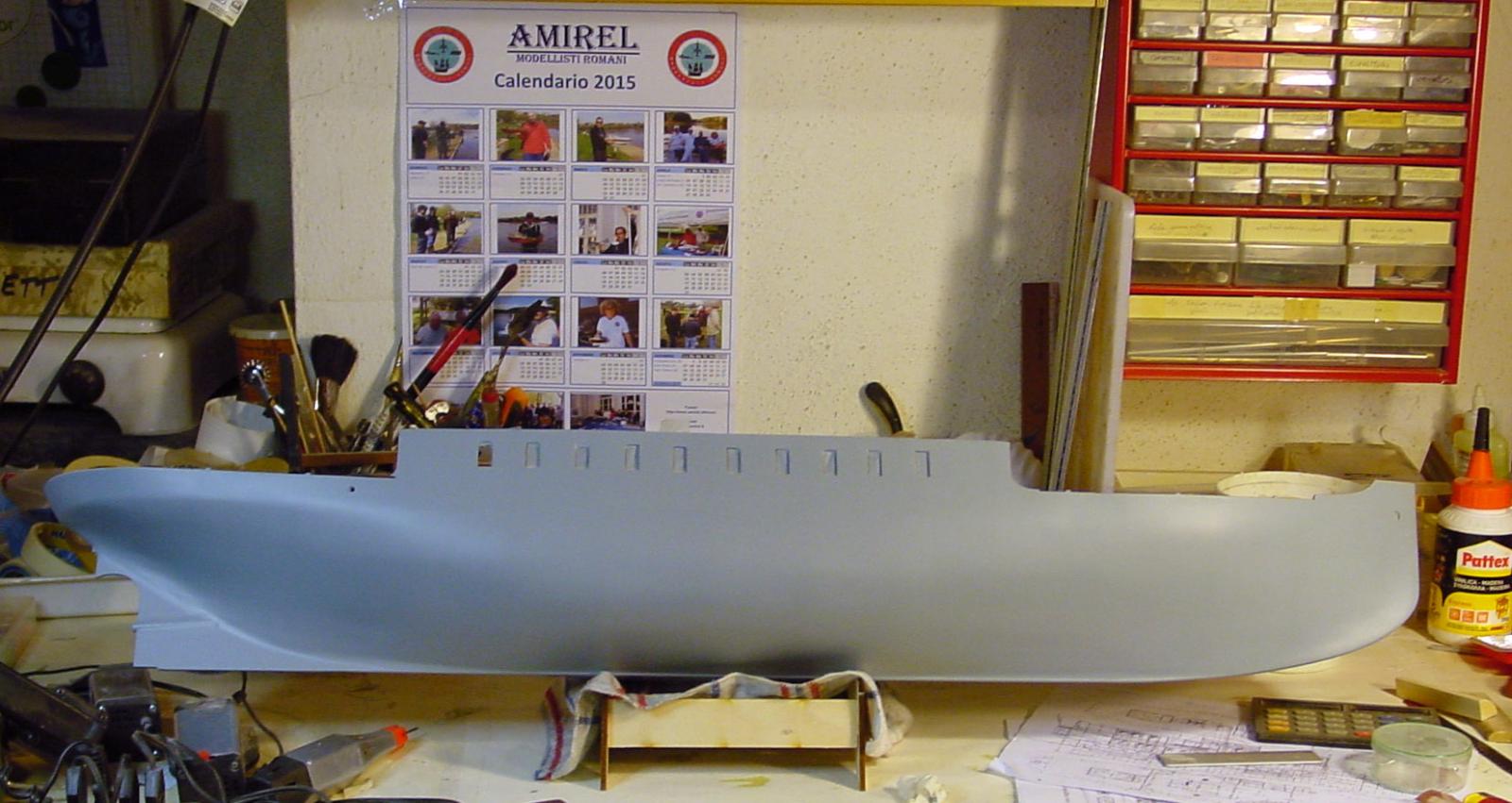
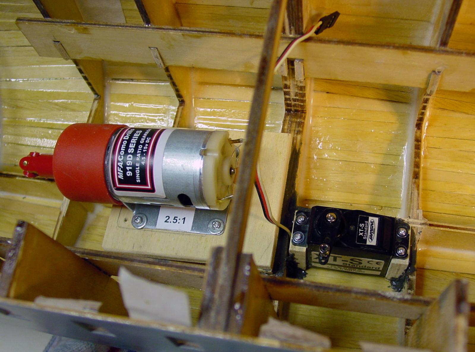
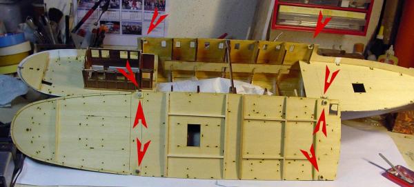
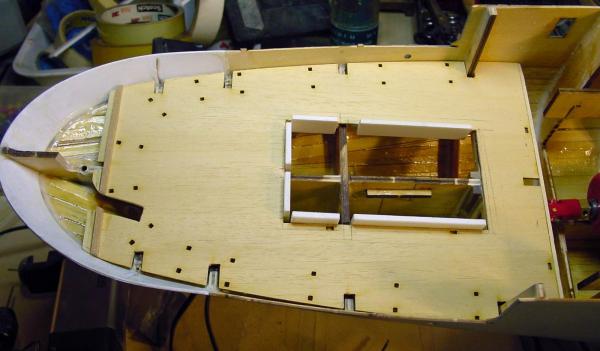
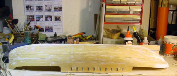
Now: first coat of gray primer. At this point I started to prepare the lower deck. Obviously the kit plan to paste the bridge as it is provided all glued without any opening. But having to build model RC, I created an opening at the cab and I cut the back end to access the rudder horn. Positioning the lower deck aft, I realized that a mistake made earlier: the opening of the cabin does not allow access to the servo steering, too small opening. So I moved the servo much further back, near the motor and I had to redo his support. Now everything should be ok. Finally, I realized from construction drawings and even watercolor shown on the box, and from the photos of the boat sailing, there are portholes in the side !! Sure! There are more living rooms below deck. In the kit are not expected. So, I proceeded to do all the holes for the portholes. Good nigh, for me is deep night, I go sleep


-
Thanks Bob, I hope so because I have already experienced this configuration on other models.
-
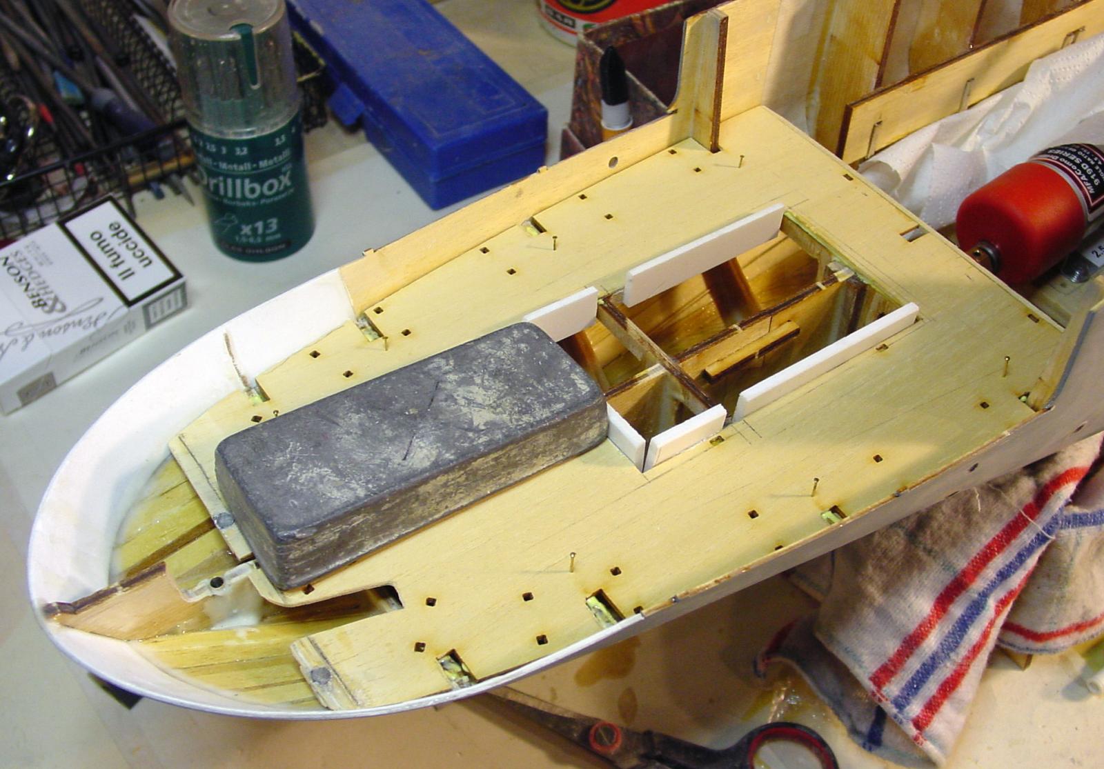
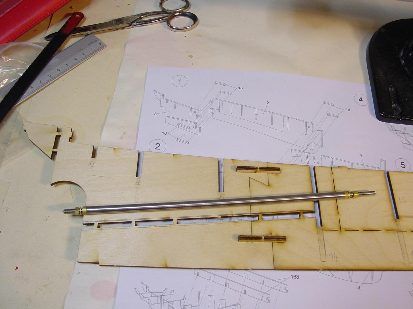
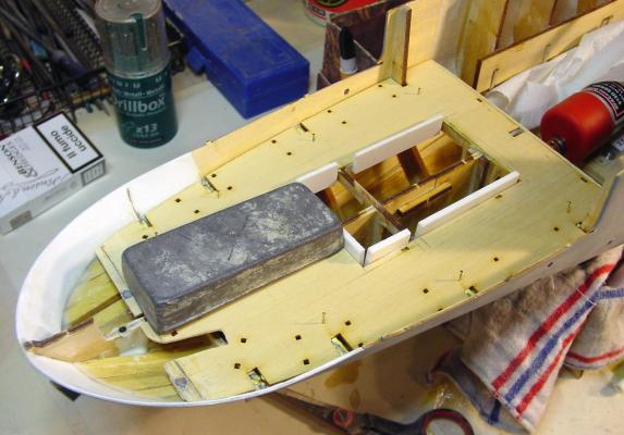
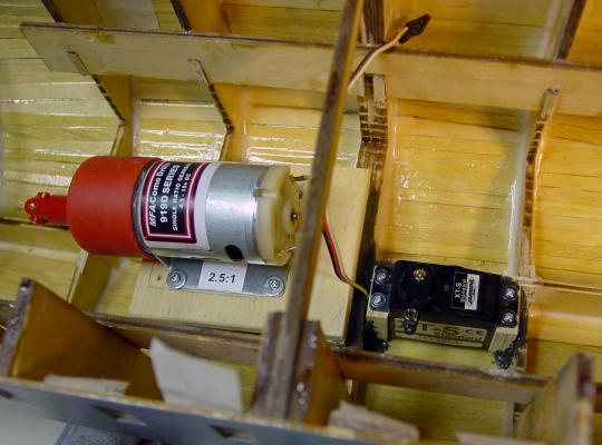
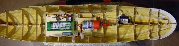
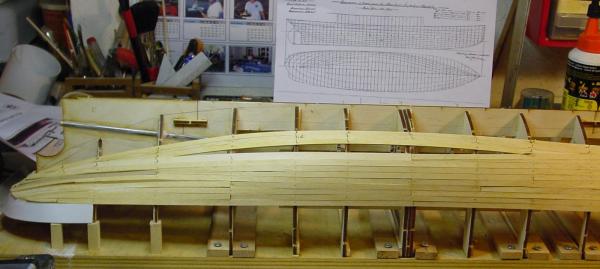
And here is some small progress. After giving a coat of epoxy resin inside and outside of the hull, I sanded it all with all the tools at my disposal: electric sander three heads articulated type razor (fits all curves ), disc sander, files and rasps manuals of all forms, finally sandpaper hand. At this point, before proceeding with the construction, I have prepared the arrangement of the elements motorization. The axis with its tube (which I had already inserted and glued with epoxy resin with glass beads) is Caldercraft Fine Line 4mm. steel M4. On the tube, in the end part inside the hull, after having drilled a hole, I inserted a small brass tube 3 mm. soldered with tin and steel-reinforced liquid (epoxy). All this works to grease the shaft, just push the fat with a syringe into the tube. The electric motor is reduced to 2.5: 1 is an MFA 950D 385 English that can be powered from 6 to 15 V. I think it will feed with a NiMH battery 7.2 V. The universal joint between the axle and the 'shaft is a universal type with inserts of the righteous diameters. The rudder servo is Jamara Standard. After this important step, I continued building still following my logical succession and never that of the original instructions that are to a static model. For now I glued the high walls of the passenger cabin below and the sides of the bow and stern. After a good sanding, I plastered all remained uneven with epoxy filler and then sanded again. Finish for now, after next progress...

-
Hi, burnside, I saw your topic and I appreciate your building that was very useful to me. But I think that Nordic Class was powerful in the faithful reproduction so I have to add details that are not in the kit. Besides that I have to invent solutions for RC
-
Yes, right, Nils, me too sometime I used this method but this time I forgot...
-
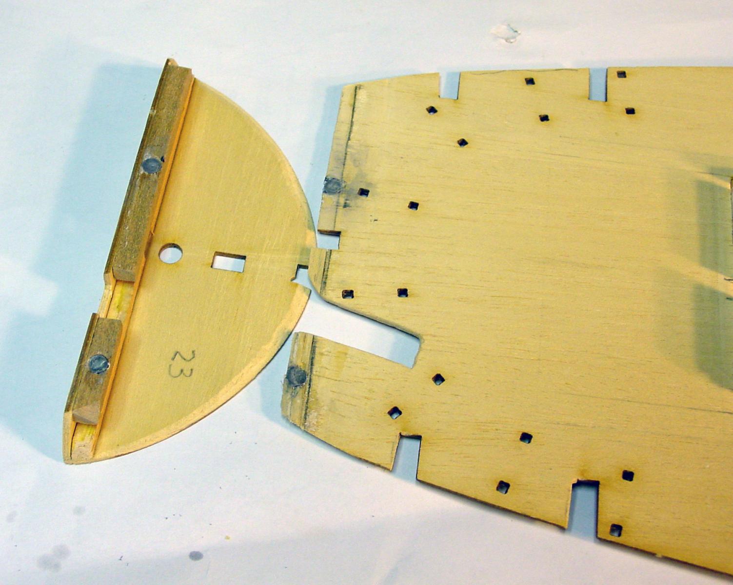
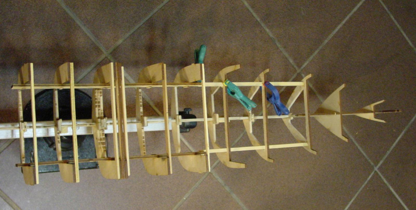
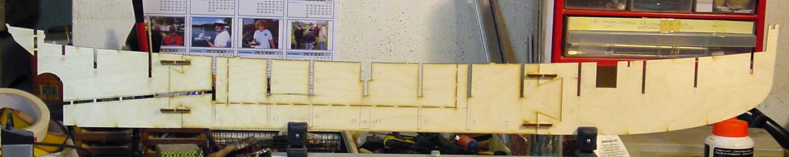
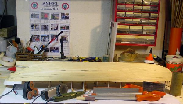
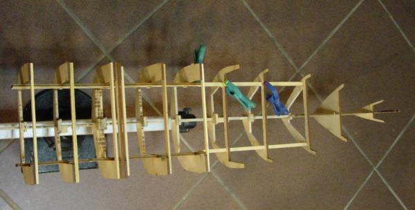
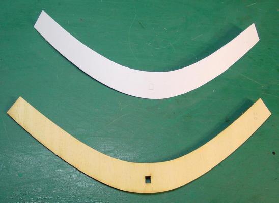
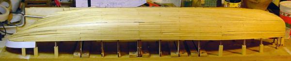
Thanks to everybody for the kind words . I emptied the ordinates to lighten the weight an also to allow the passages of cables and linkages. Then, after building a structure, I started laying the planking with strips of basswood. At this point, I realized that at the stern, in order to glue the strips , I had to stick the side of the stern. In the kit is 1,5 mm. plywood. I kept it in water overnight and, the next day, when I tried to bend it gently (the curve is very strong), it broke immediately! So I decided to use another material: polystyrene that bends very easily. After I proceeded with the planking.


-
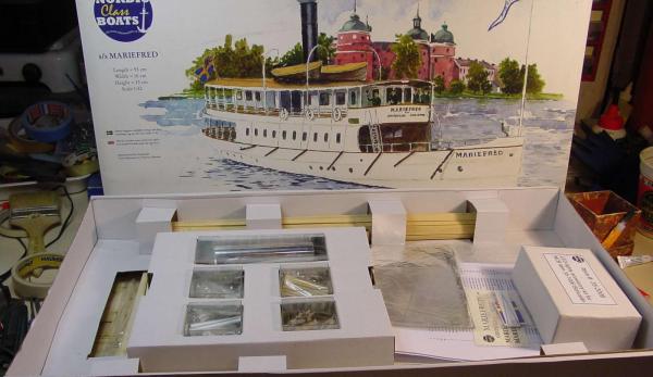
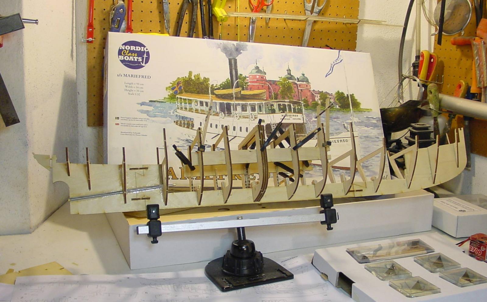
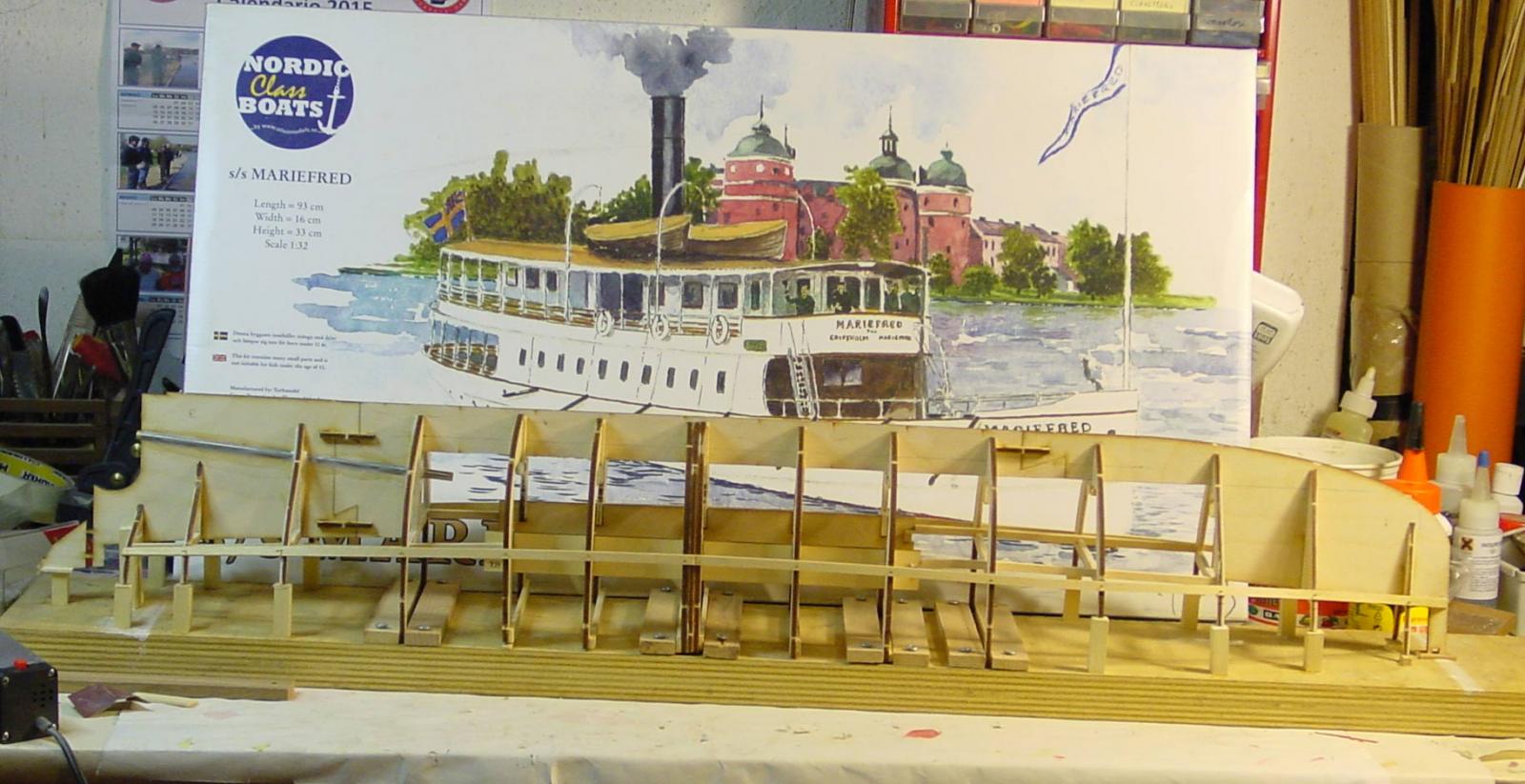
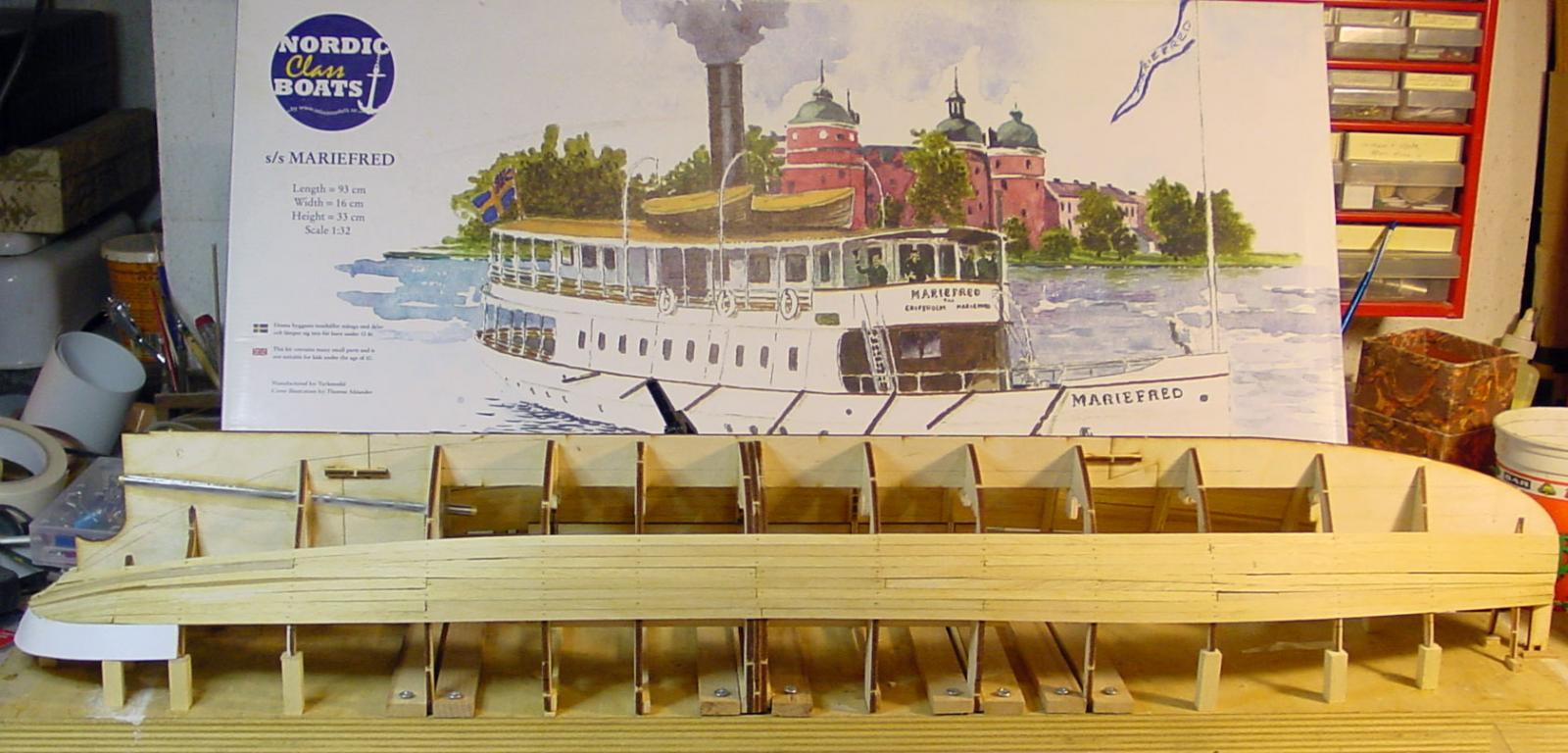
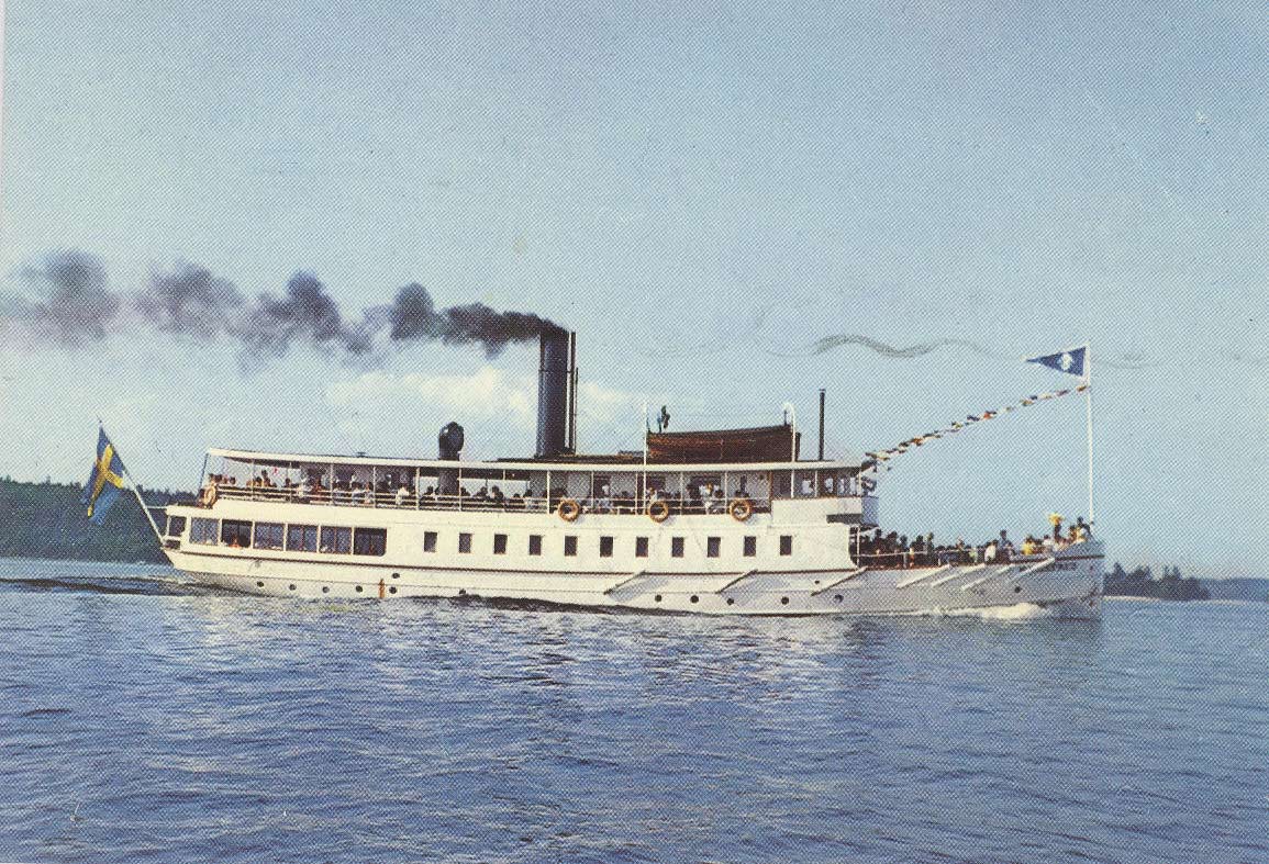
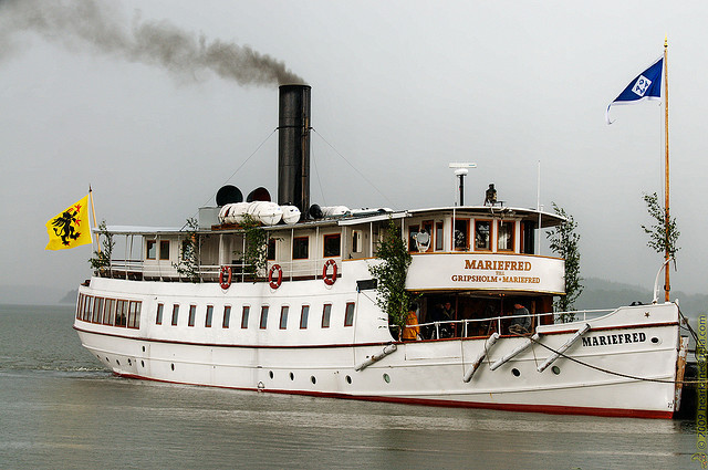
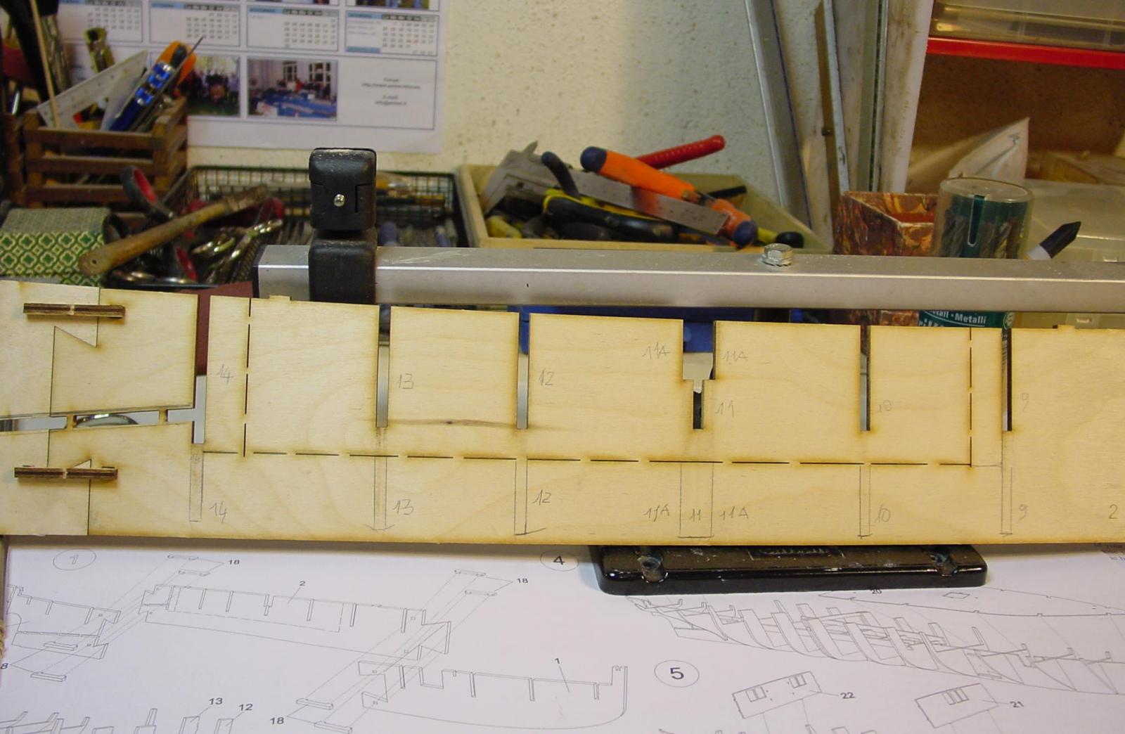
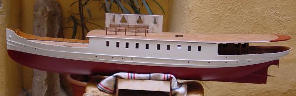
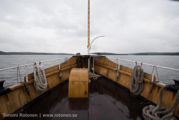
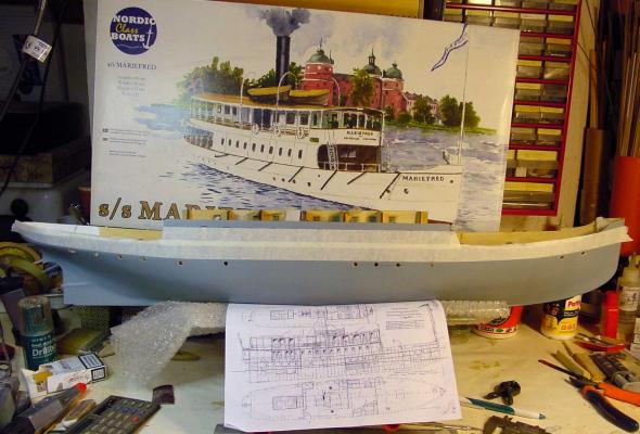
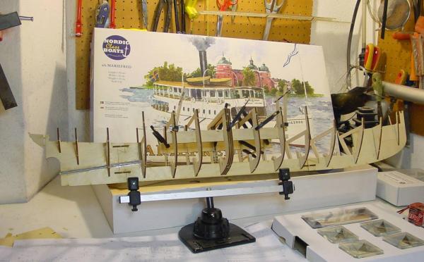
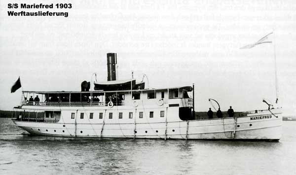
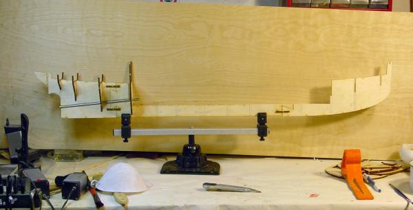
Some time ago I bought the kit of the Nordic Class Boat, produced by Turk Model, steamship Mariefred Sweden in 1/32 scale. So, now, I decided to open this new yard. Before beginning, I did a lot of research on the web, to keep records as accurate as possible about the history of this vessel. Here is the report. Built in 1903 on construction Wilialm Linbergs Varfs in Stockholm, Sweden, this boat, with dozens of others, it was freight and passengers between the capital Stockholm and the small but important city of Mariefred Lake Malarem. The distance between Mariefred and Stockholm is 33 miles. Around the '30s, especially mercantile traffic began to unfold on the road. This boat like many others, was, in those years, sold as scrap. Thanks to Nordic culture that preserves and restores the old boats,ship Mariefred and many others, were bought back by private groups, preserved and restored. Steam ship Mariefred today is still under way for sightseeing and is notable for having maintained the original steam engine. Compared to the ship in 1903, to date, only the first bridge at the stern has been modified with the addition of panels with windows closed on the passenger cabin, also wood lifeboats have been replaced with modern inflatable boats. 1903 1960 2000 And now we come to the substance of this kit and to its realization RC. The kit does not correspond at all to the states, not at all prepared for RC. It does not provide removable elements. It would be decent for the realization static interlocking millimeter, accessories a bit ugly, but acceptable from a neophyte. Too bad, though, that the instructions do not give ikea illuminations on how to proceed to the plating at the bow and stern, almost impossible with the strips. I will have to invent something. But it is unacceptable that a kit, which costs several dollars, is so much lacking and bad. I founded originals plans so I can understand more Piani1.tiff Piani2.tiff Now I begin the construction. Certainly not as instructed, who say to mount on the keel and paste the sides of the passenger cabin and the first two bridges! Here are picts: Keel assembled and glued and others... Ok, I'll see tomorrow


-
I'll try to post my work in progress of my RC Mariefred from Nordic Class Boats. It's a kit declared as Rc running. But it is not so. Forgive the mistakes in English, if you prefer, I speak in italian language, let me know... But important above all is picts and picts ands yours comments and suggestions! Good