

Gbmodeler
-
Posts
464 -
Joined
-
Last visited
Content Type
Profiles
Forums
Gallery
Events
Posts posted by Gbmodeler
-
-
Just waiting for the 48 star U.S. flag I ordered to come in the mail from Canada....
- NavyShooter, Paul Le Wol, KeithAug and 15 others
-
 13
13
-
 1
1
-
 4
4
-
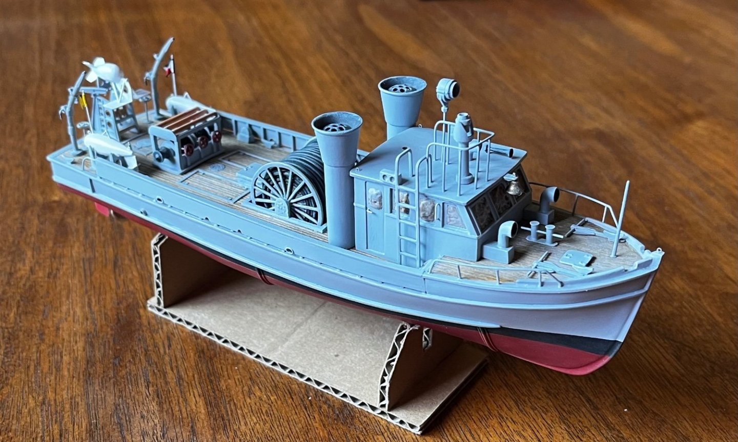
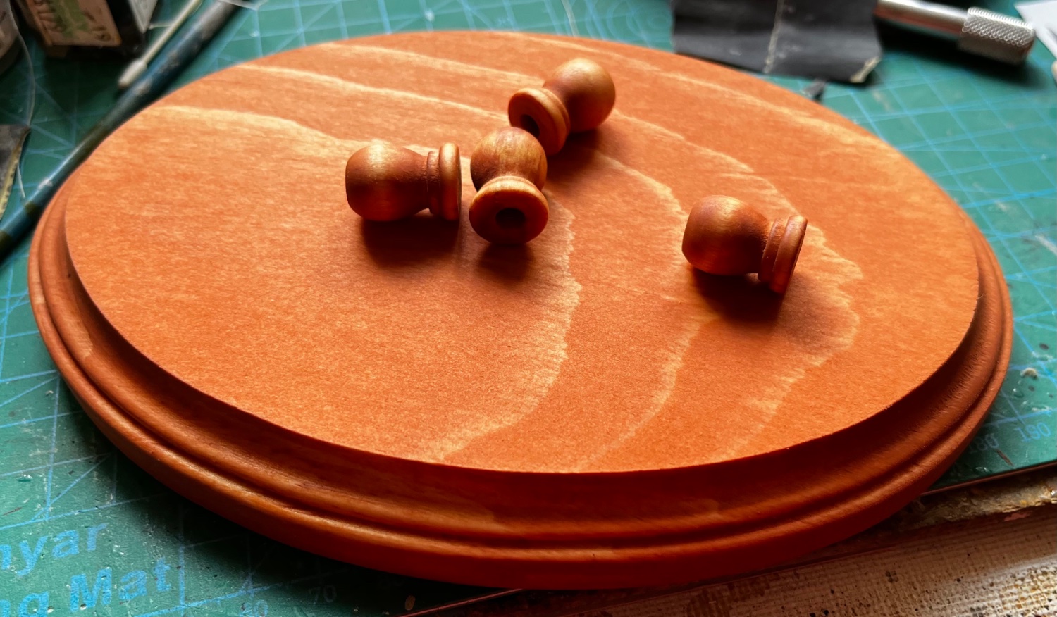
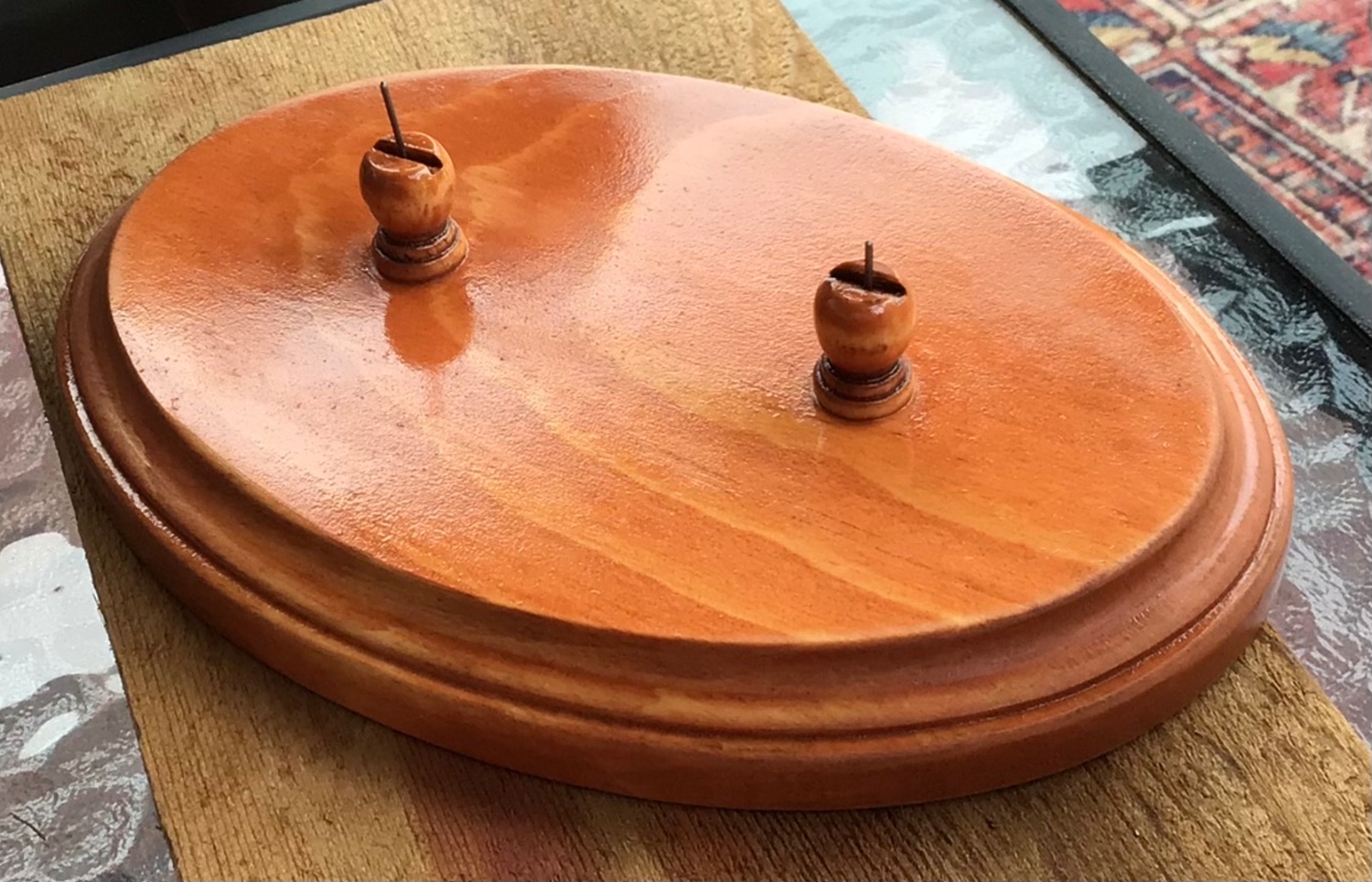
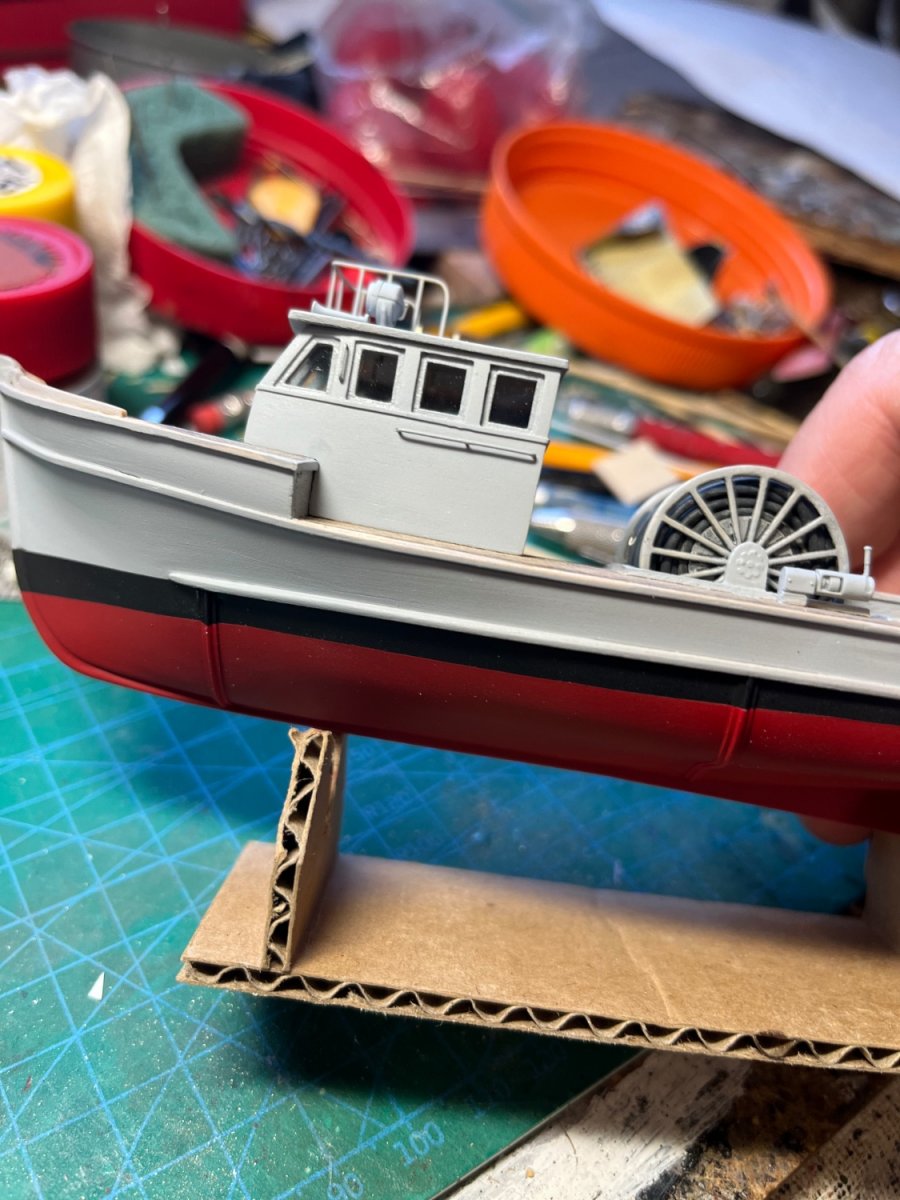
Started building the display base using a $1.99 pine plaque and some decorative finials from the local craft store. Strong piano wire will pass through the stand and into the boat via holes drilled through the keel. I also notched the finials to accommodate the keel....

Letting the stain soak in....

Some little details I did not mention earlier: a compass-looking decal in the pilot house stand, coated with Testor's Clear Parts Cement; a little cleat (from wire) and rope (invisible thread monofilament) on the jackstaff, and; an MV Products lens in the search light...
-
I completed the rigging and applied the decals. Then I applied a pin wash of black artist oil paint heavily diluted with mineral spirits. The base coat of paint is acrylic, so the excess from the oil based pin wash can be removed fairly easily. It can darken/stain the acrylic paint, but an acrylic gloss coat over the base paint helps prevent that. I like the way the pin wash brings-out the tiny details, that would otherwise go un-noticed...

-
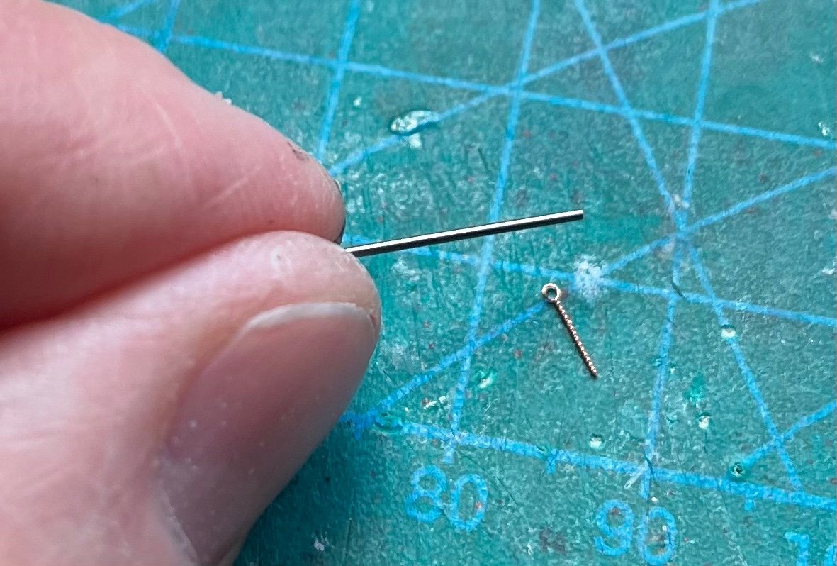
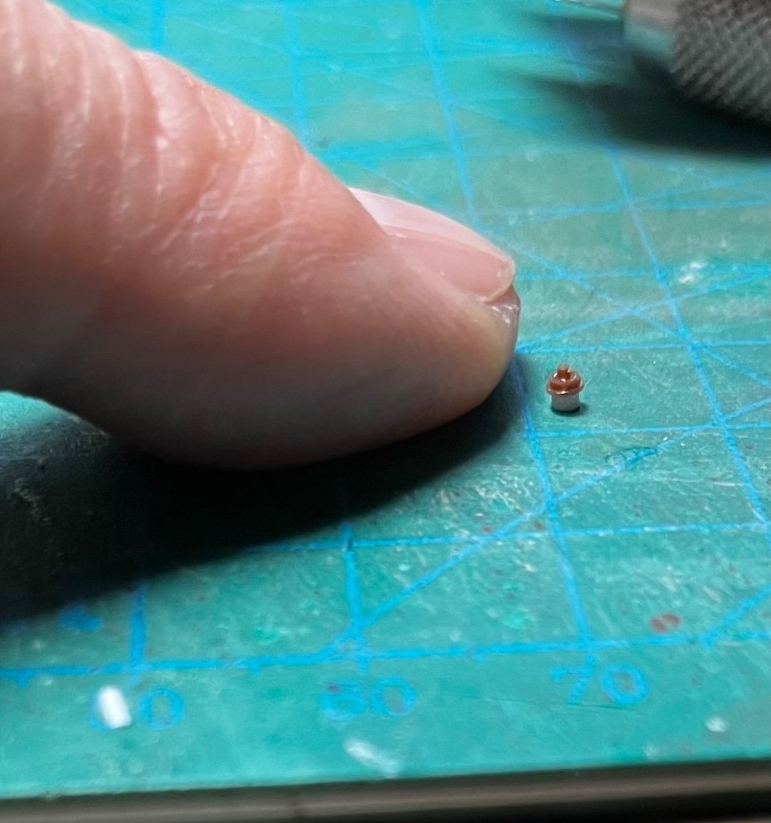
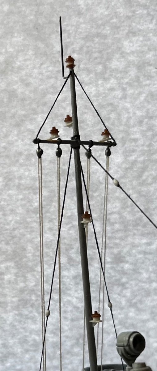
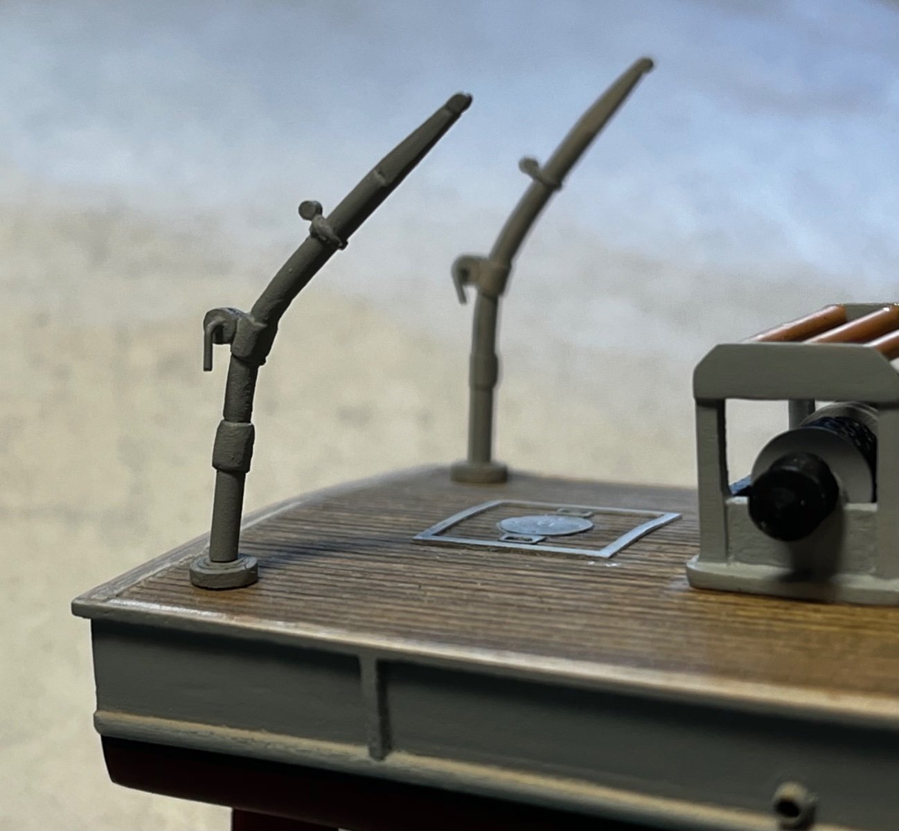
Making hooks for the cranes, and running lights for the mast...
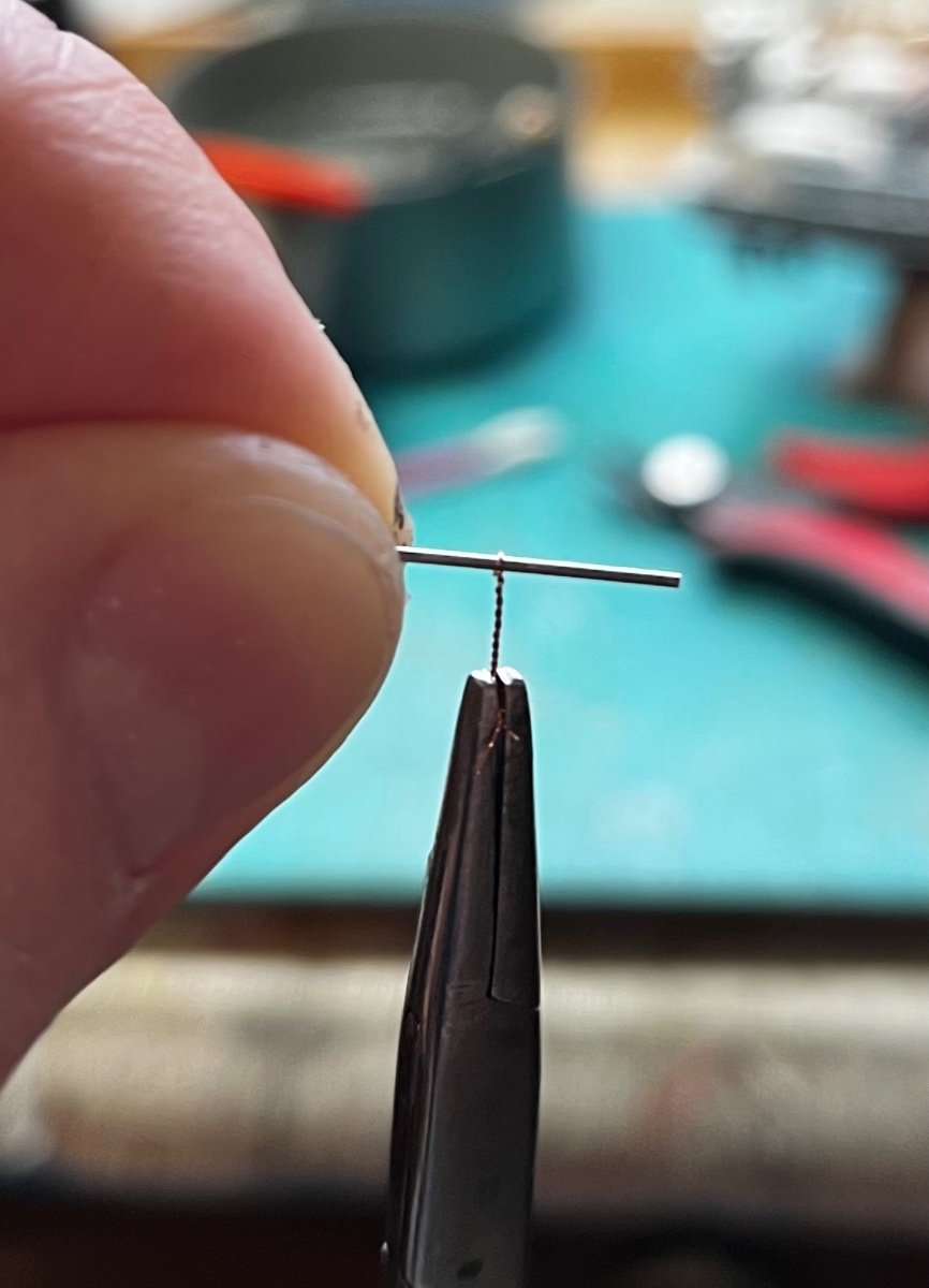
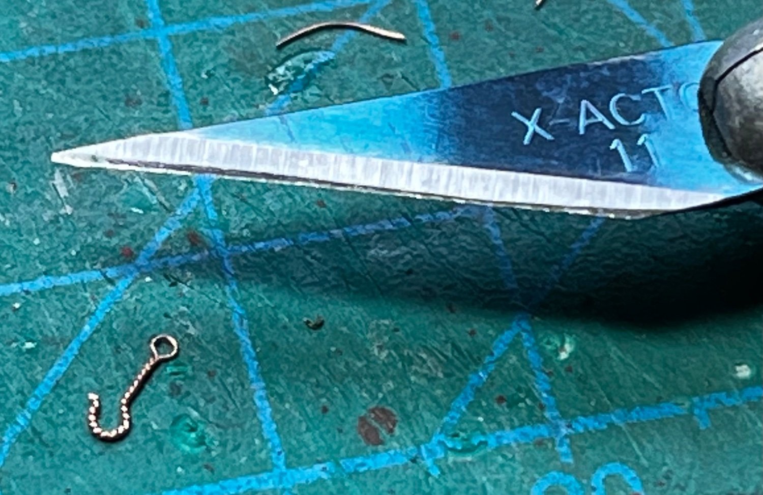
Hooks start life as a hair-thin piece of copper wire. The wire is twisted around a pin-vise bit and then bent to shape as shown below...


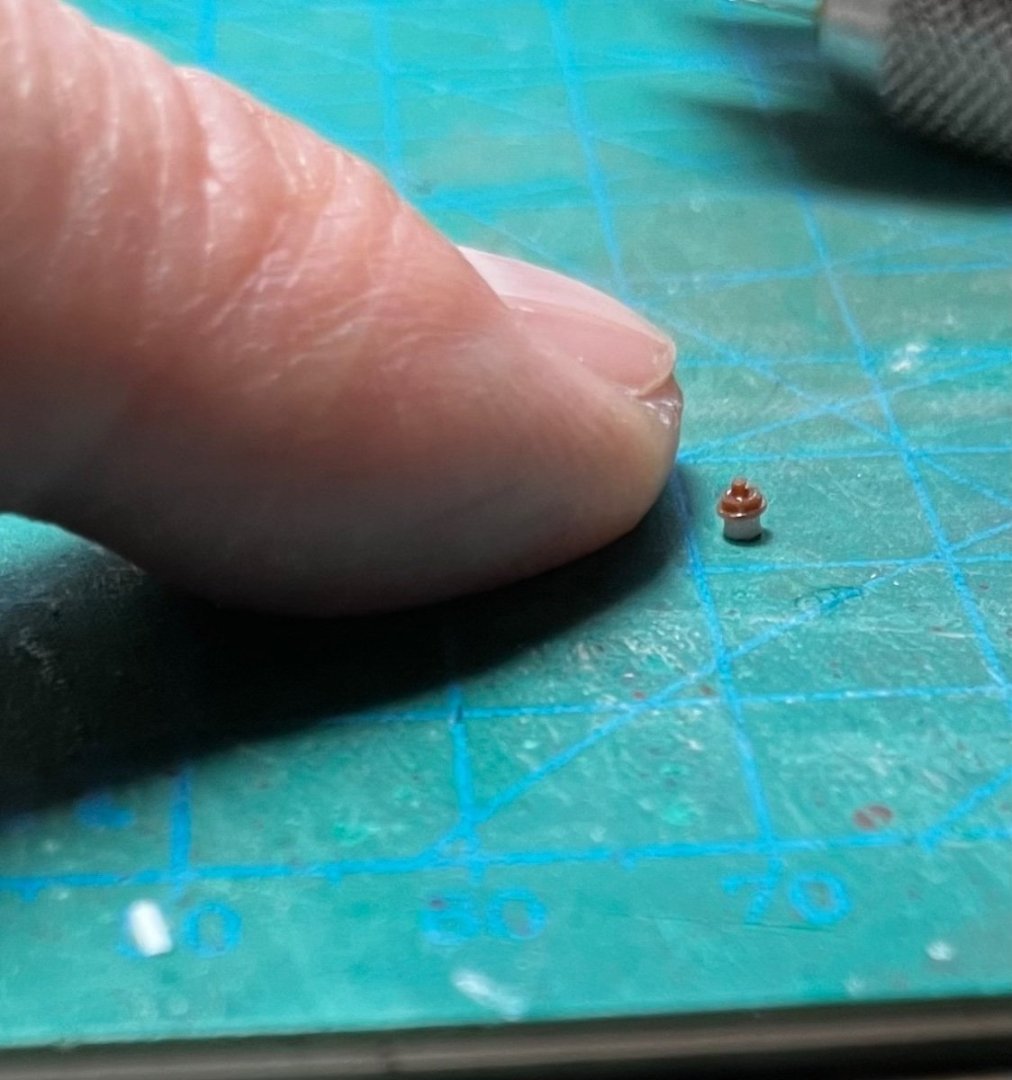
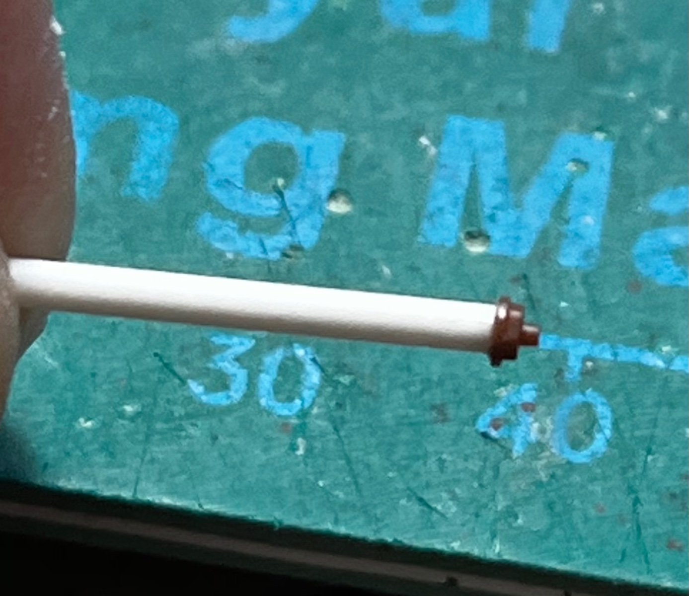
The running lights were made from styrene rod and strip, along with plastic model railroad bolts. The bolts look like the light covers I saw in photos of the real thing...
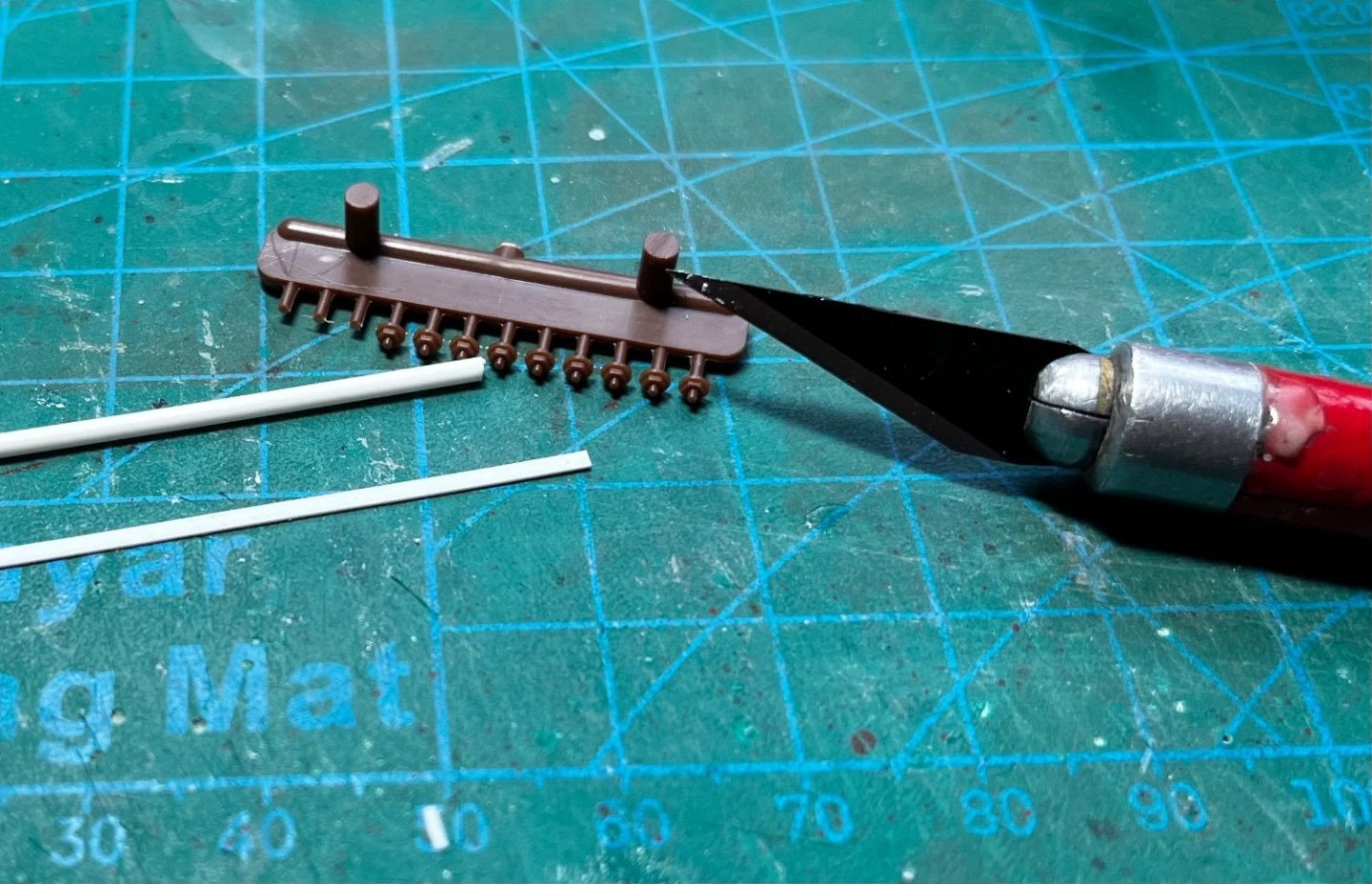
The bolt was glued to the end of the rod with plastic cement...

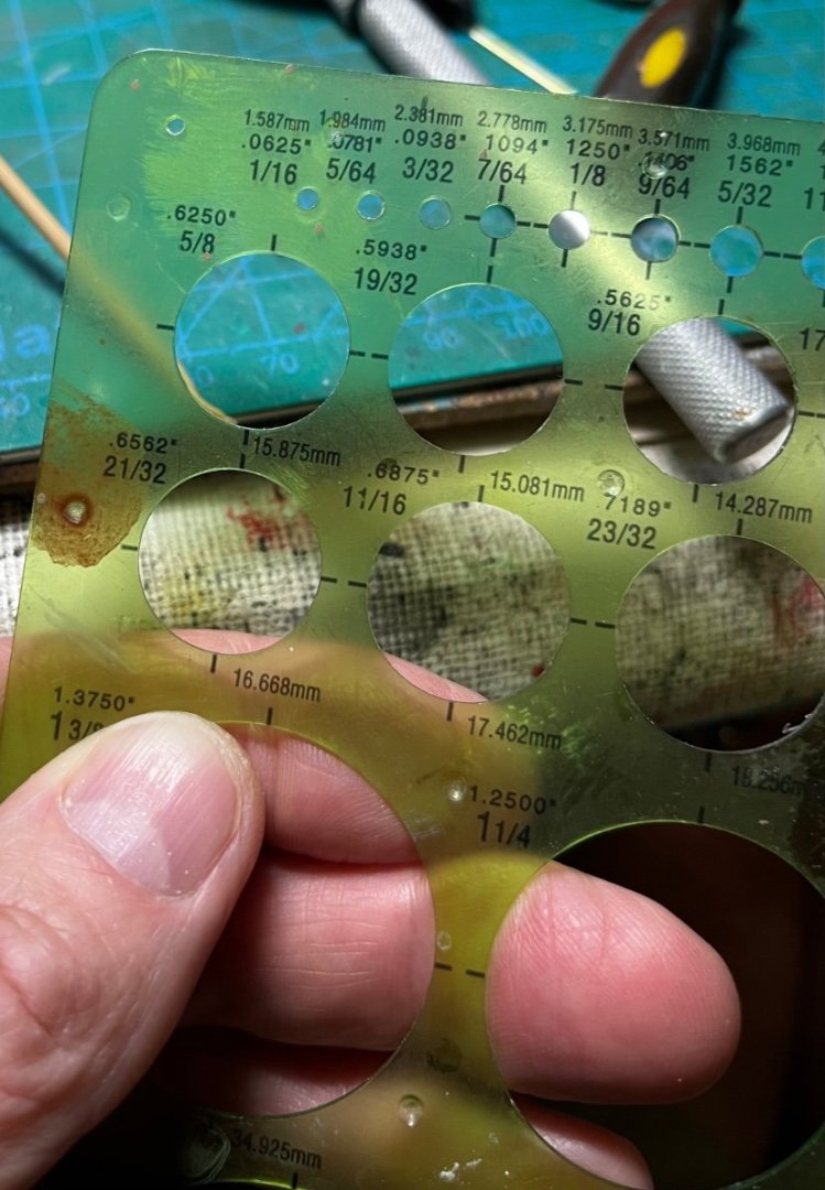
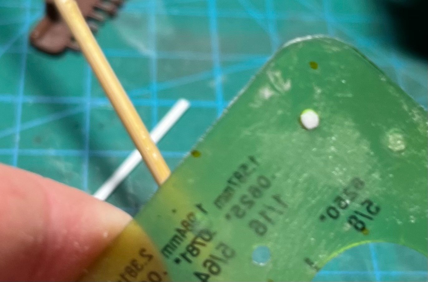
Then, in an attempt to make all the lights the same height, I put the rod through a circle gauge and filed off anything that stuck out. The smallest hole in the circle gauge was too large, so I had to drill my own...
The plastic strip was used for platforms, and glued to the mast. A little wedge of plastic sheet formed the support bracket...

-
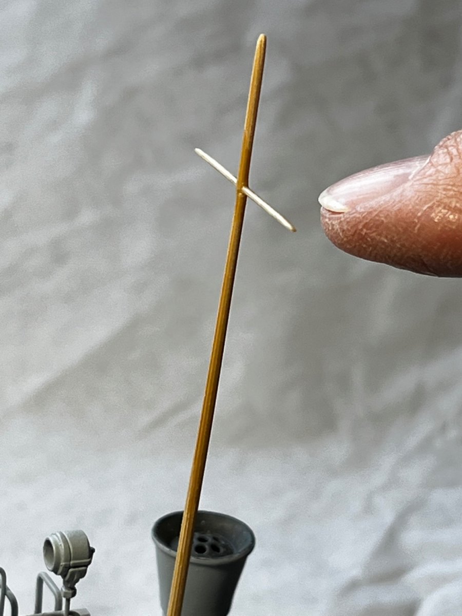
Starting work on the mast, which was made out of a sanded-down and tapered bamboo skewer. A small sliver of turned basswood was used for the cross-tree, and inserted through a hole drilled in the mast. To strengthen the cross-tree and its junction with the mast, it was saturated in very thin CA glue.

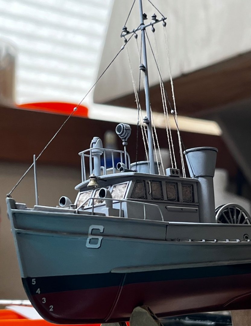
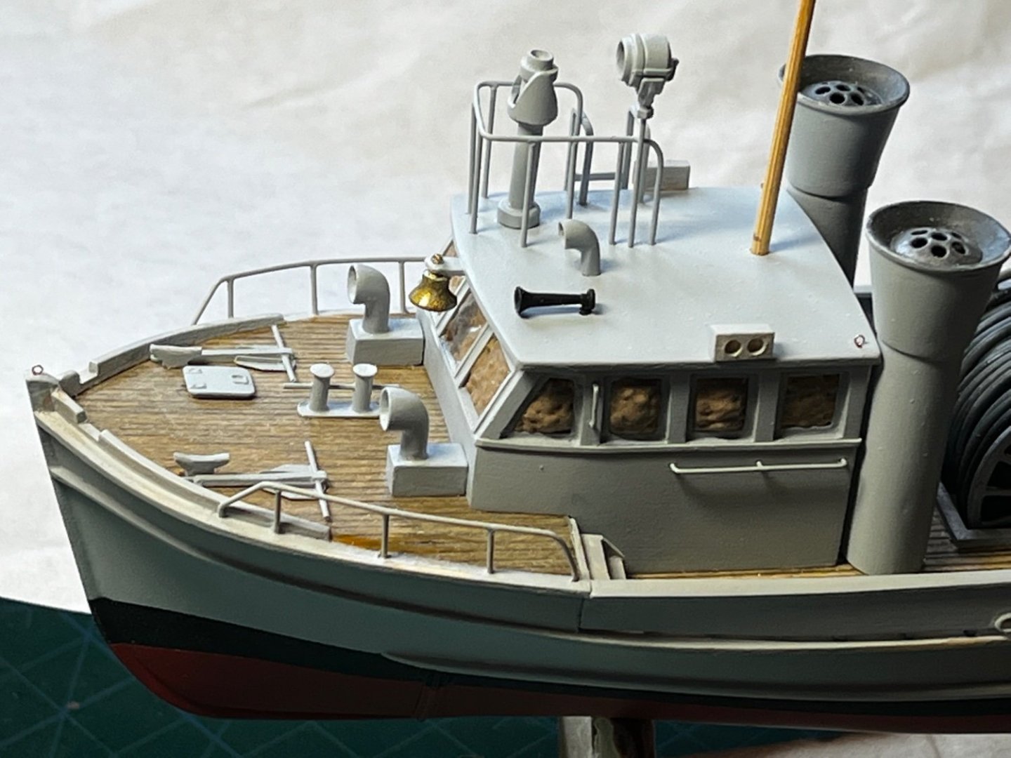
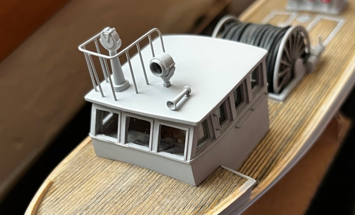
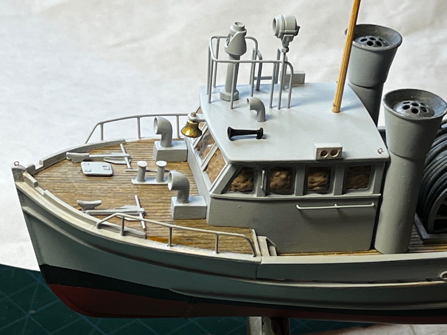
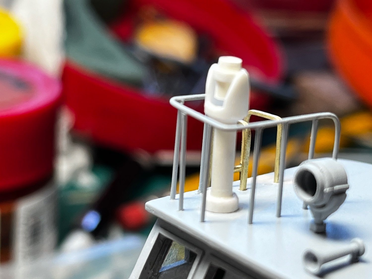
Further research of the Number 6 boat showed I had to change some things around. The pilot house spotlight had to be elevated by the railing and a small air vent was situated in its old position near the center of the roof. You can see how the windows are masked with "Silly Putty" to protect the "glass" from future gloss-coat and dull-coat paint applications. The gloss-coat will be applied to facilitate decal application, and before the mast and rigging are installed. The dull-coat application will be last, to finish off the model. You will also notice the model railroad bell I installed earlier, but forgot to mention...
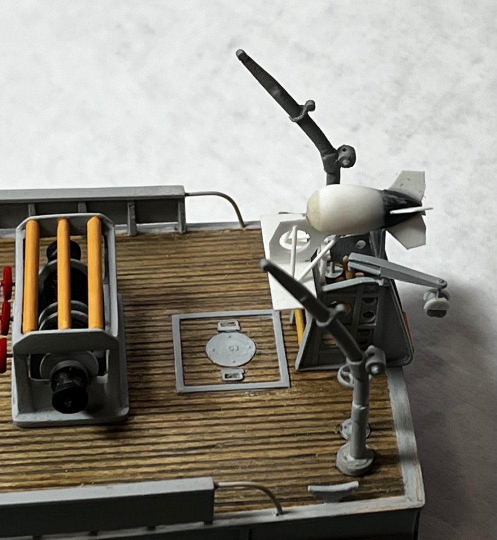
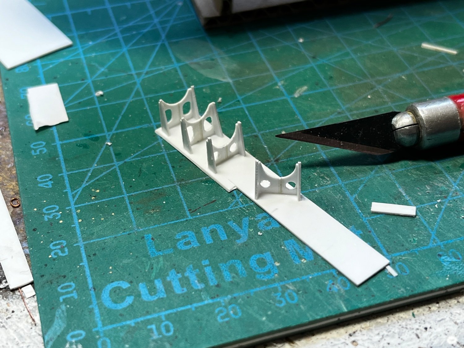
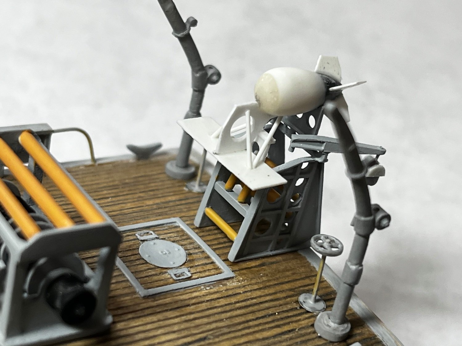
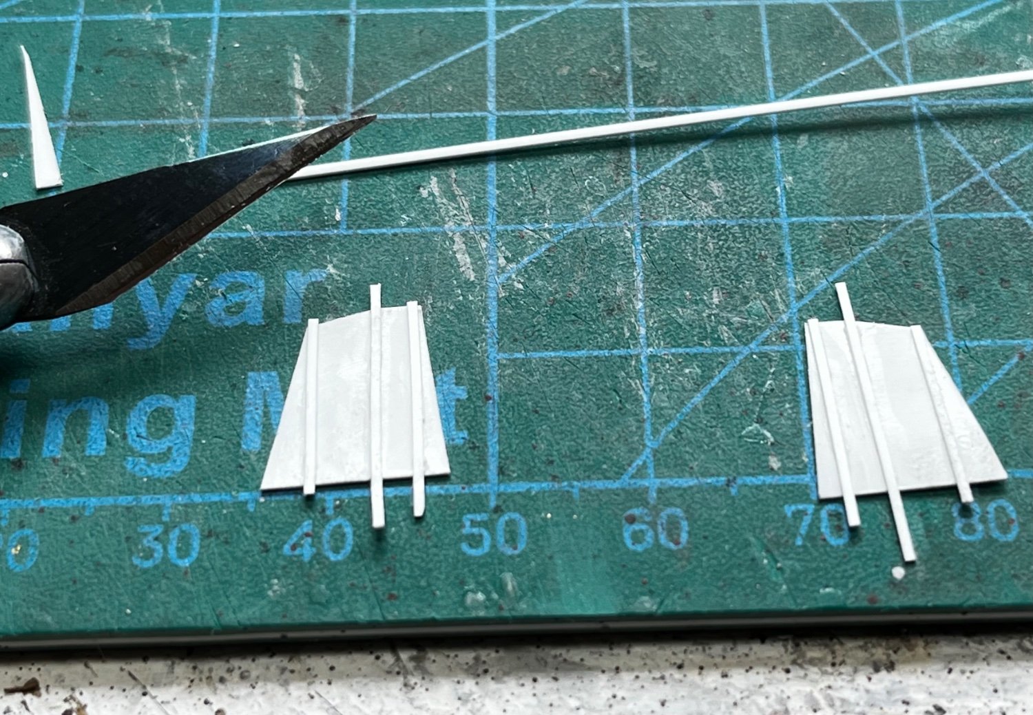
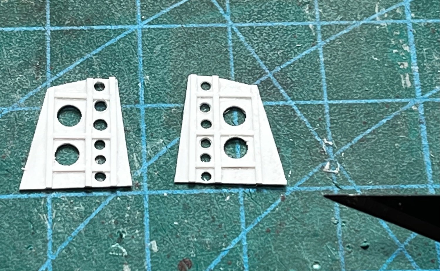
Besides the mast and rigging, the last structures to complete were the racks for the oropesa floats. These were made from plastic sheet. I built them on a plastic sheet base, and the cut them out later...

Here are the floats mounted on their racks. The flags are made from paper...
After a little light dry-brushing, I think she's ready for the gloss-coat and decals!

- Knocklouder, GrandpaPhil, KeithAug and 13 others
-
11
-
1
-
4
-
4 hours ago, Roger Pellett said:
Your model just keeps looking better and better.
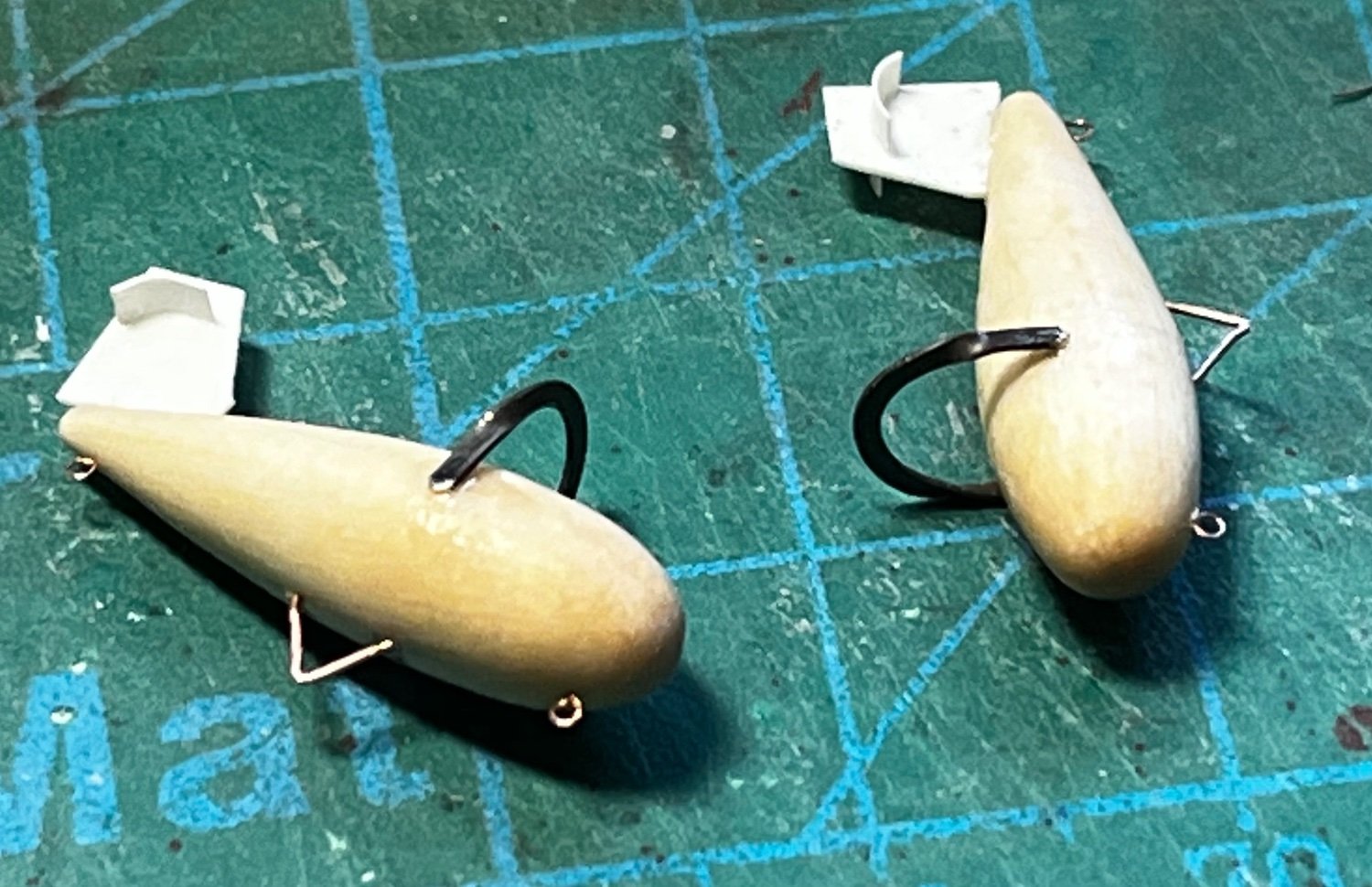
Strictly speaking those are not paravanes. Paravanes included the depth control, splaying out, and mine cable cutting functions in one unit. They were used to protect ships not engaged in minesweeping in waters where mines could be present.
The short, fat, item is a “hammer box.” Towed behind the boat, it created noise to set off acoustic mines.
The other two are floats that were attached to the ends of the sweep cable when sweeping contact mines. These floats would have performed two of the three functions of paravanes; depth control and splaying the sweep cable outboard from the vessel doing the sweeping. They often were had little flags on top to give those conning the vessel a visual reference. As I posted earlier, the actual cutting of the mine’s mooring cable was performed by cutters fastened along the sweep cable.
Roger
Thanks Roger! I was hoping someone would give me more info on the equipment!
-
More little projects that are filling my days: First, the boxes for the side-lights were pretty easy. Scraps of left-over basswood plywood from the keel and frame seemed like just the right thickness. I plan to find or build some lenses for the lights later...
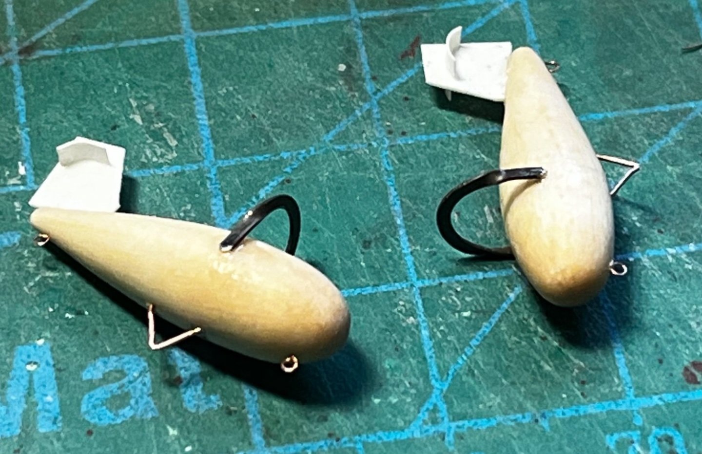
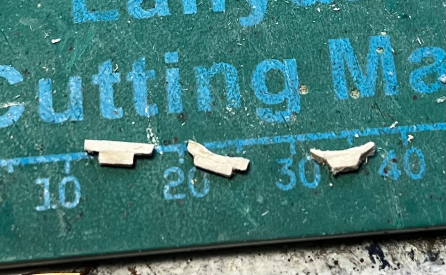
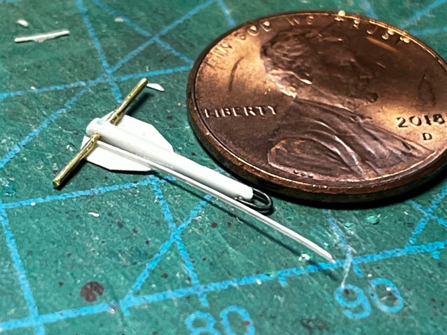
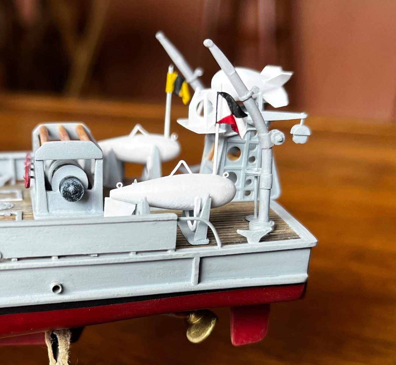
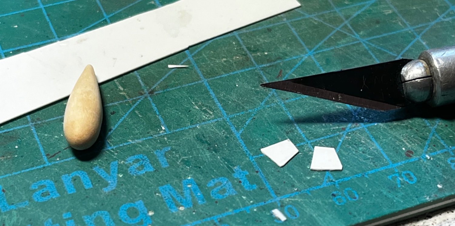
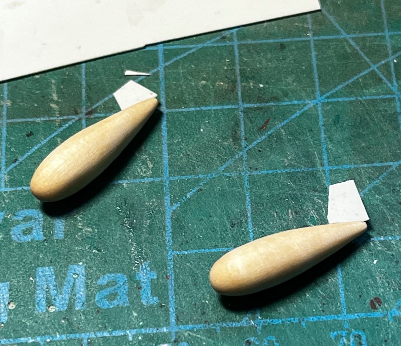
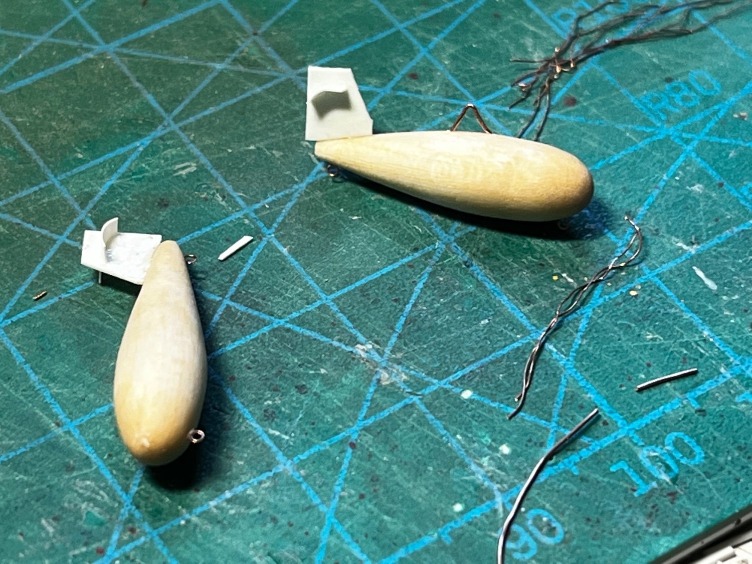
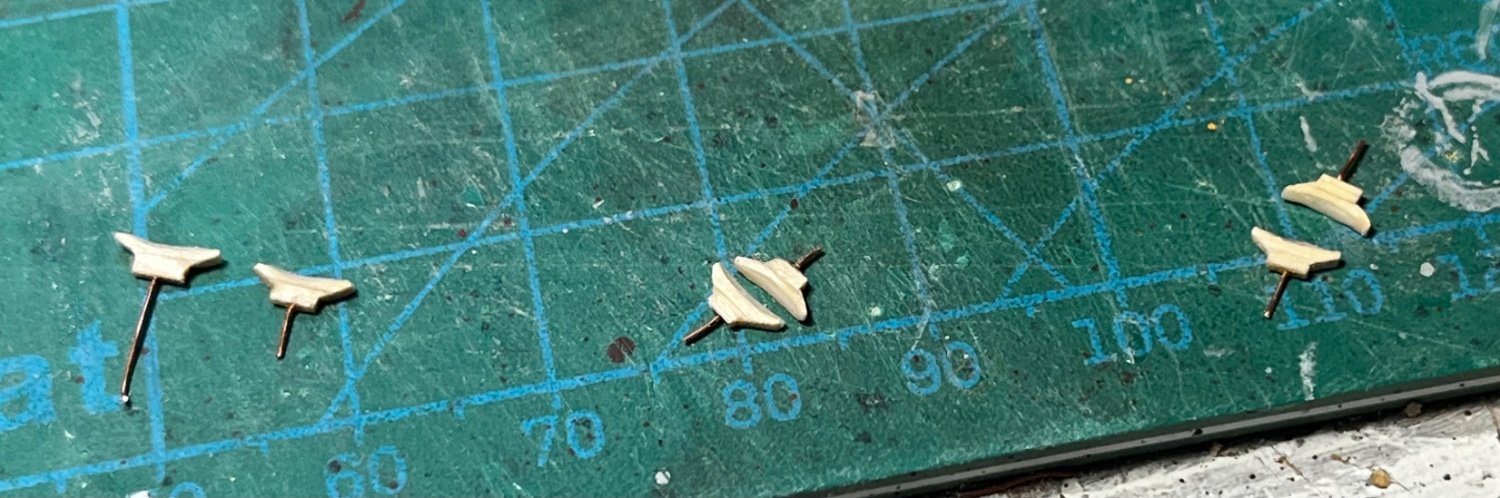
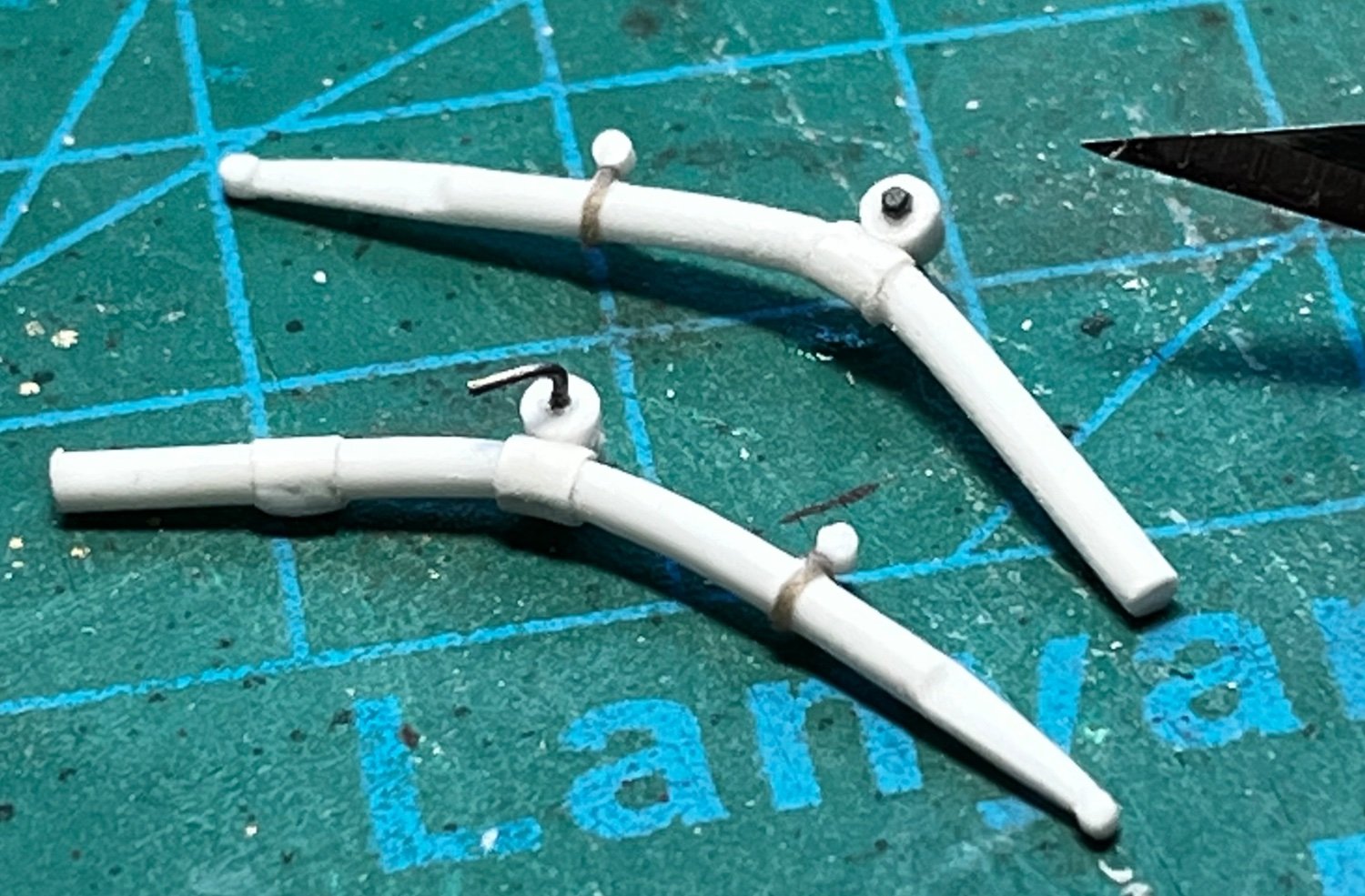
The paravanes were much more daunting. I built the body for the short, stubby one from styrene tube. The tube was plugged with glue and old model sprue, then shaped by hand with files, emery boards, and sandpaper. Fins and wings were crafted from styrene sheet and rod. A bit of wire will be used for the lift ring...

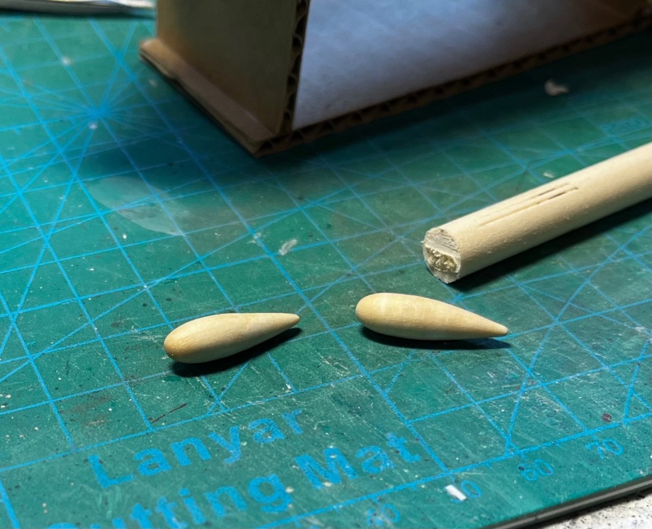
The side paravanes were shaped from soft wood dowel (I think a very soft pine). Again, plastic sheet was used for fins, and bits of wire for lift rings, etc. Pictures of the real thing show them with a flat, twisted loop of metal on the bottom. This might be a mine-cable cutter? Anyway, I was able to re-create it with a thin brass strip. The metal was first heated to take out the temper and make it more pliable. Glad we have a gas stove....😁


- GrandpaPhil, Canute, mtaylor and 7 others
-
10
-
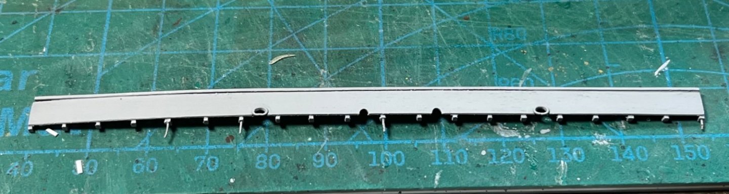
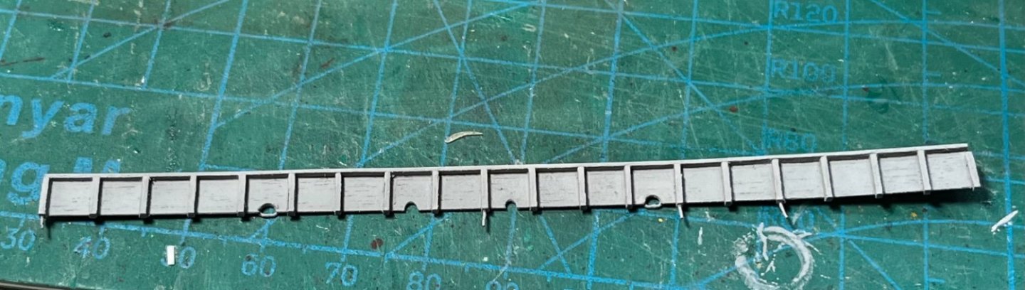
The bulwarks were a little problem because of their design. In real life, they were constructed like most bulwarks, except a thin strake at the deck line was omitted to form scuppers. That was contrary to what I usually build.
Normally, I would continue planking above the deck line to form the bulwarks, and the scuppers are drilled out later. This method usually creates strong bulwarks attached to the planks below. I add false "ribs" (or frames) along the bulwark, later.
However, on this boat, there is a missing strake along the deck lines. How can I attach the bulwark to the hull without frames. I was a little afraid that by omitting a strake along the deck line, and using false frames, the bulwarks would be weakly attached, fragile, and easily damaged. However, it appears to be okay, even though I used false frames along the bulwark...
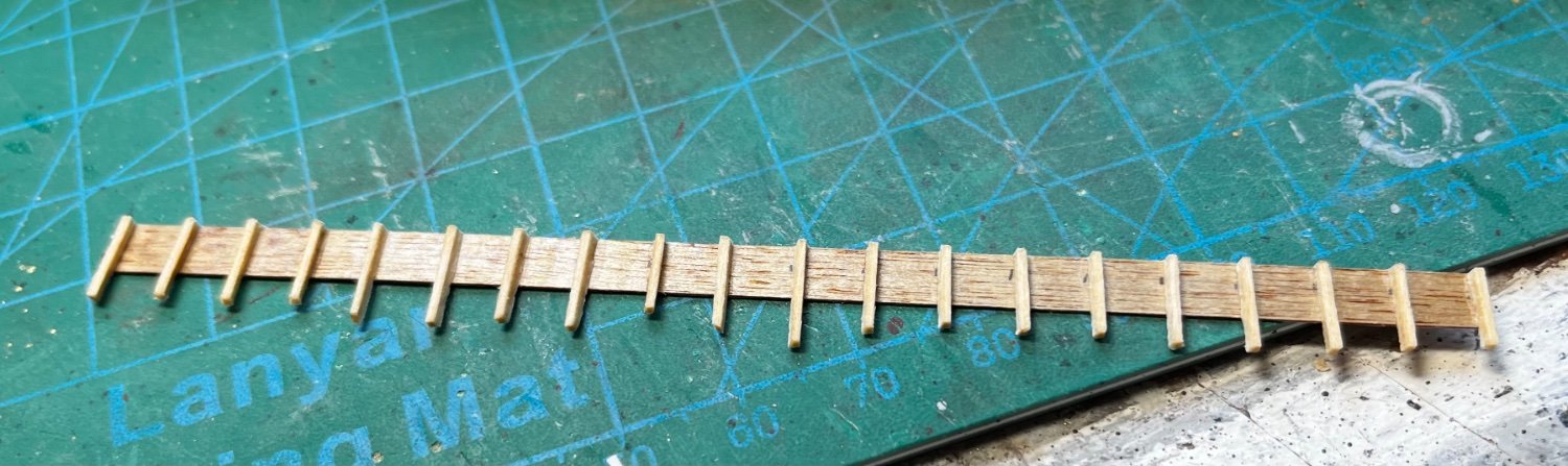
The bulwark plank was made from thin birch plywood, like is used in model airplane construction. False basswood frames were attached with PA glue.
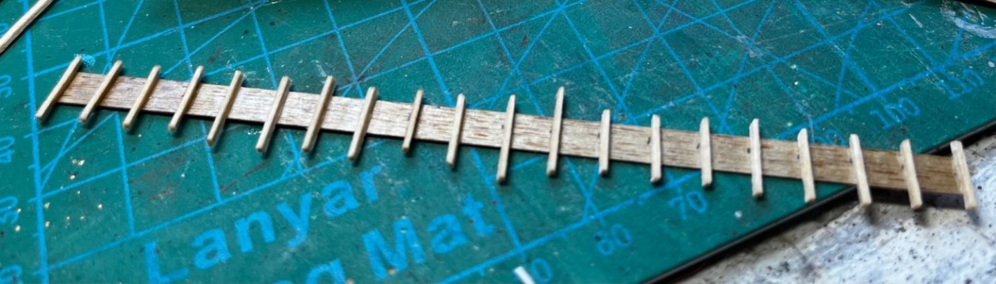
The top of the ribs were cut off and sanded smooth to the plywood...

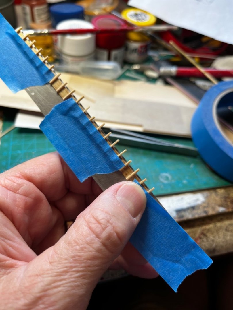
The bulwark was tightly taped to a metal ruler so I could make the lower portion of the frames all the same length. The excess wood was snipped off with sprue cutters and sanded smooth to the ruler...
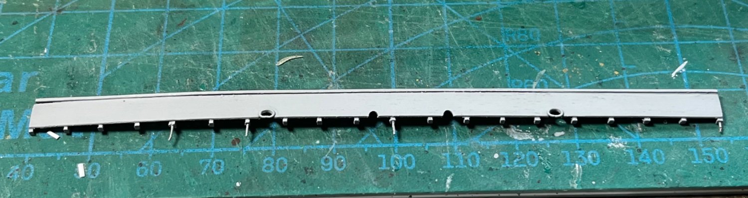
The bulkhead being tested for fit...
Howser holes and other openings were cut out, and thin copper wire was shaped to form frames around the hawser holes. Small copper wires were inserted in some ribs to help install the bulwark, give it strength, and shape it to the lines of the hull. I then primed the parts...
Holes drilled in the top plank received the wire pegs, and each frame was hit with CA glue. Here's the final installation...

- GrandpaPhil, lmagna, mtaylor and 10 others
-
13
-
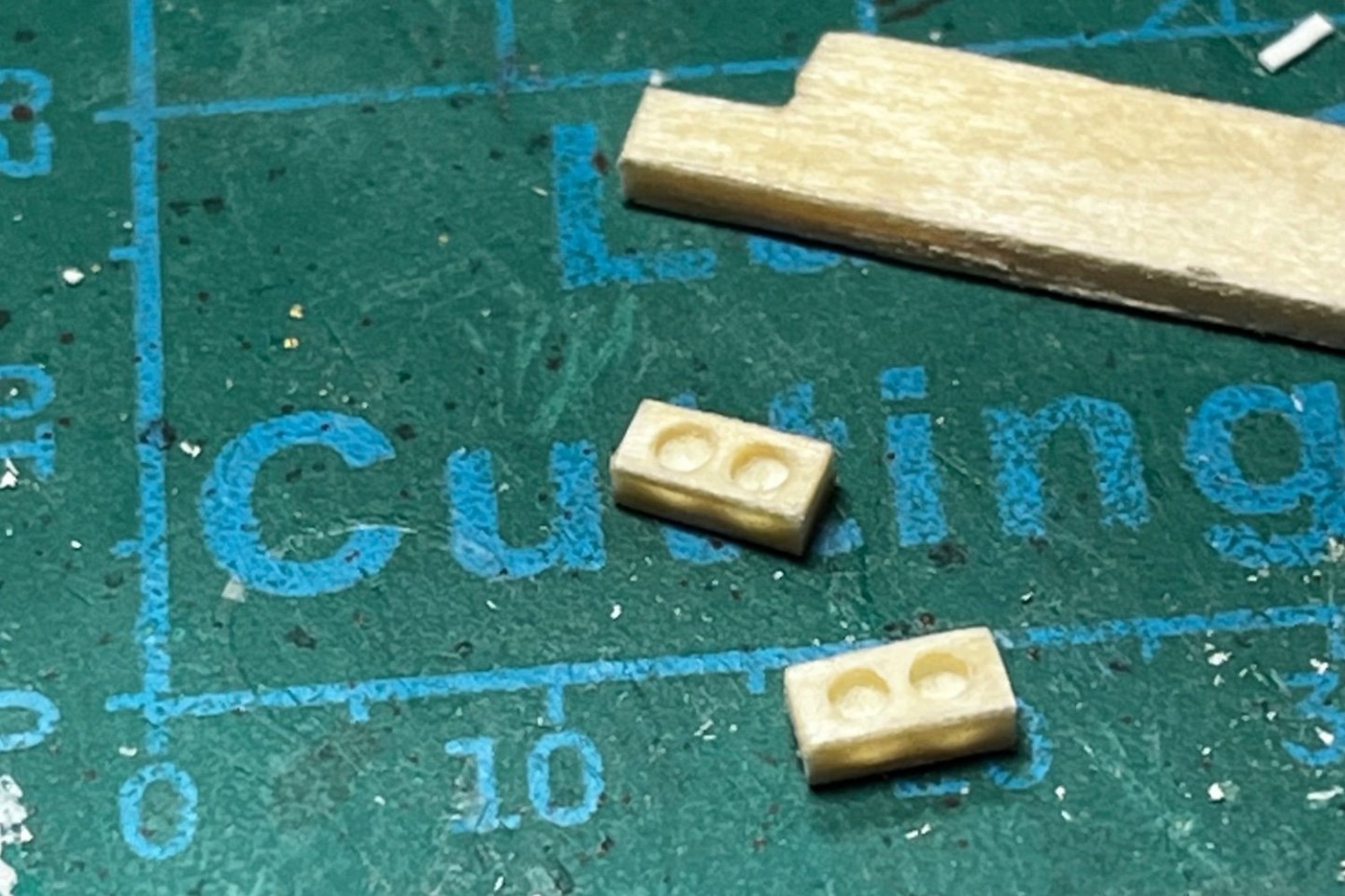
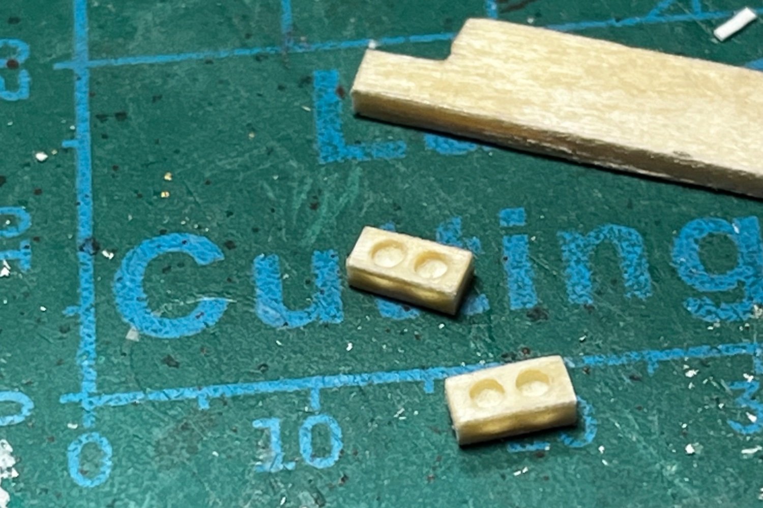
Making cleats out of basswood strips cut from a 1/32" sheet. The process starts with a long and short strip glued together with PA. Filing is done with a small round file and emery board (nail file). Little copper wire is then inserted into holes drilled in the bottom. Hopefully, this will keep them in place, even if rigging is tied to them. I also coated them with extra thin CA glue for added strength....


-
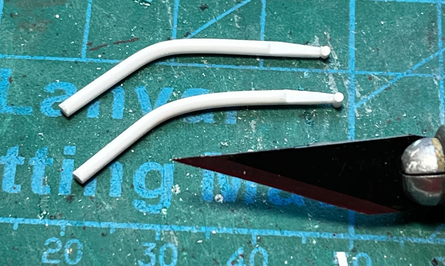
The cranes on the rear of the boat are a notable feature. They were not large, and used a hand crank, making them look a little like a fishing reel and rod. I made mine from various sizes of styrene rod, plastic strip, Grandt Line bolts, string, and some wire for reel handles. I also drilled holes in the reels so I could "wire" the cables, later...
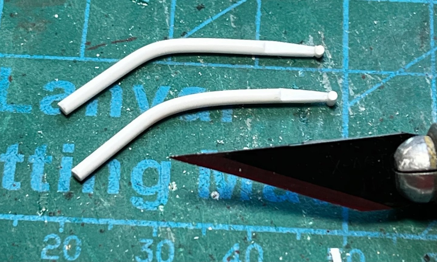
First I bent the plastic rod to shape after holding it in boiling water briefly (with tongs) to soften it...
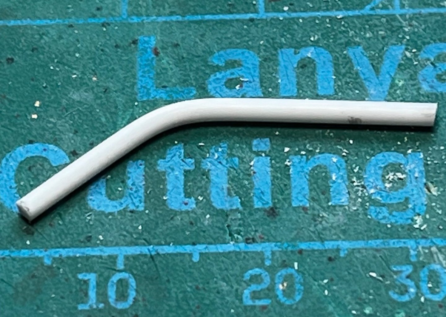
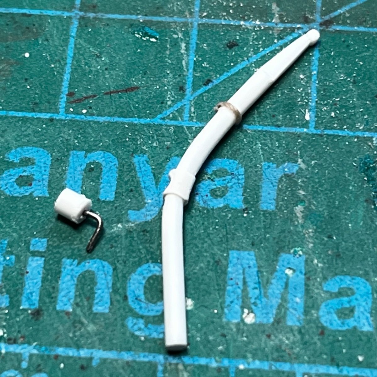
The ends were then tapered and shaped, with "pulleys" added...
Plastic strip was wrapped around the rod to represent braces; string was used for pulley straps, and; the reel was built...


Lastly, bases were made from larger plastic rod, and the cranes were painted and installed...

- Canute, Ras Ambrioso, mtaylor and 6 others
-
9
-
-
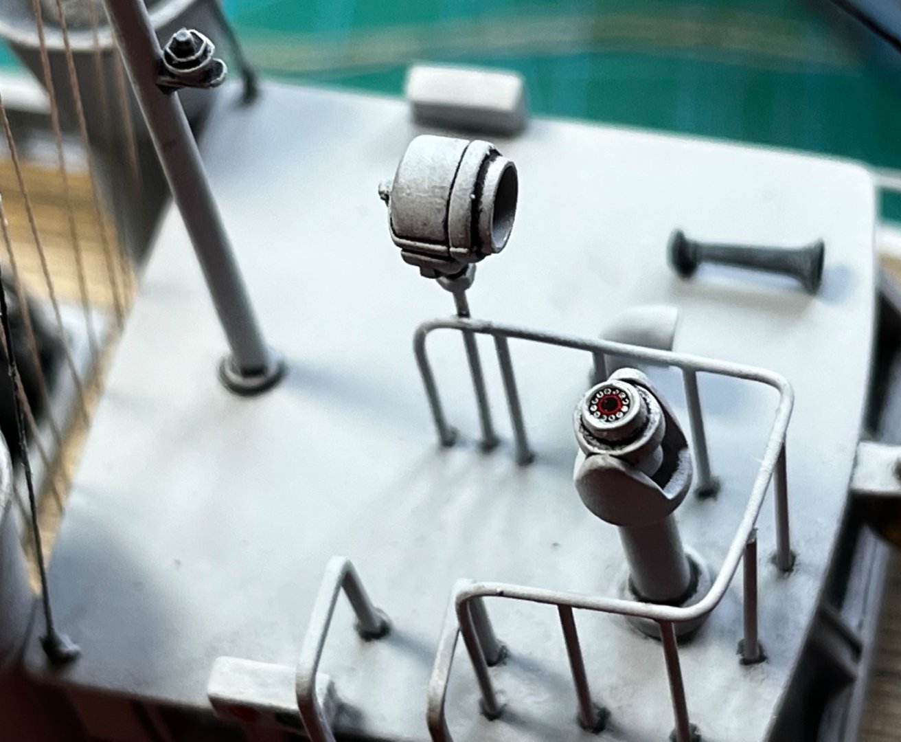
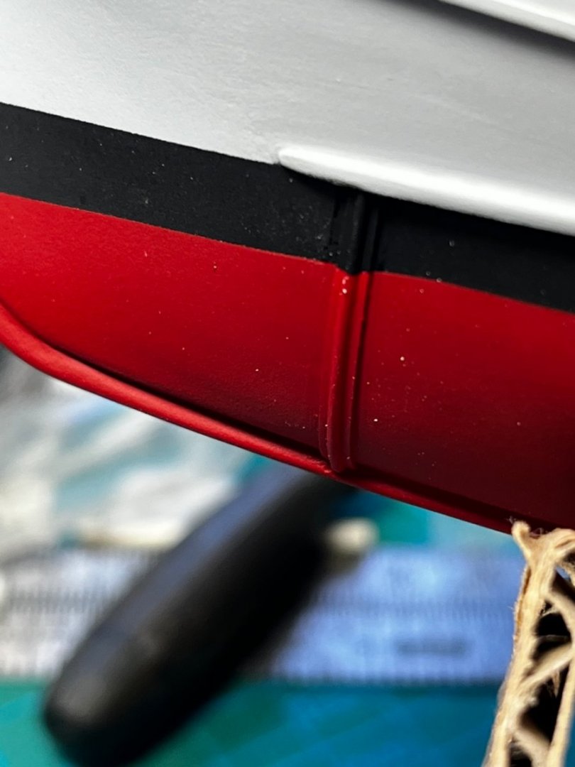
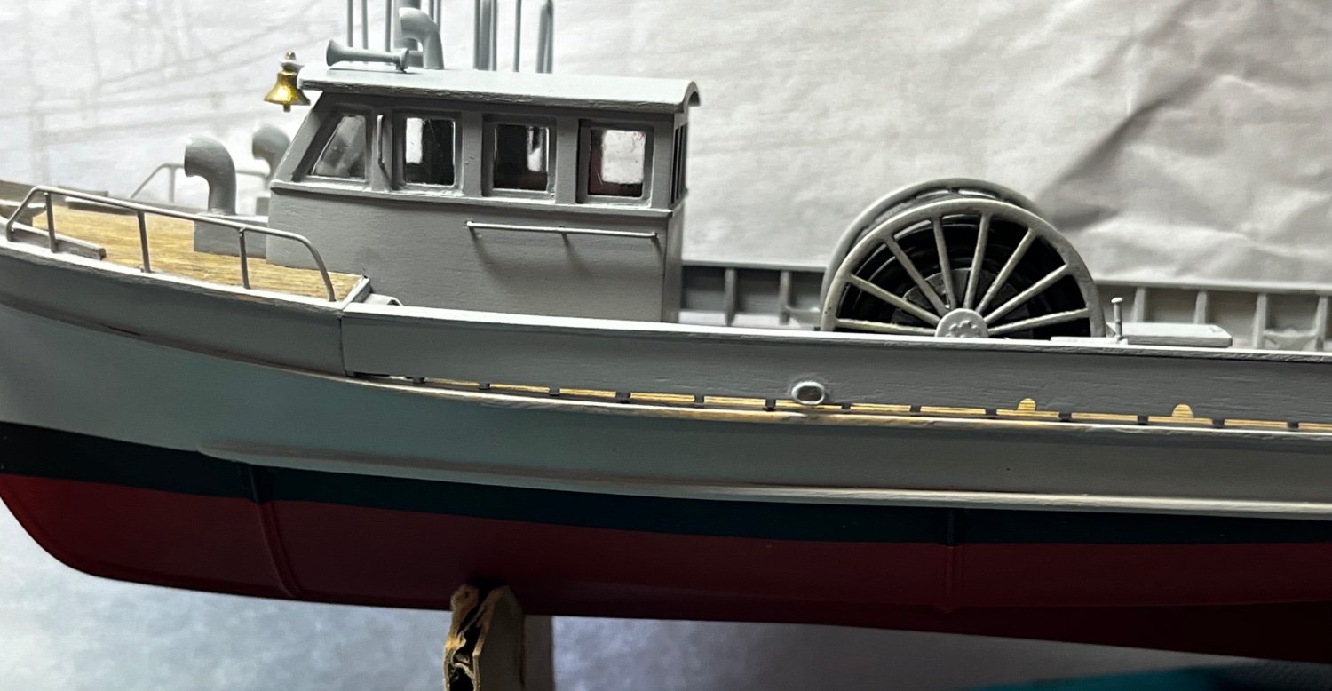
An interesting feature of these boats were the masker air-emitter belts. Two band of half-round pipes created bubbles to mask boat noises from acoustic mines. I was fortunate to find close-up photos of these pipes on the internet, and they were easy to make from plastic strip and half-round tubing. The hard part was re-painting the hull, since I put them on as an after thought....🙄

-
Here's the re-tooled alidade/pelorus instrument.

- GrandpaPhil, yvesvidal, Ras Ambrioso and 6 others
-
8
-
1
-
I think Roger and Imagna solved the WIS mystery for me. The photo Imagna posted looks very much like what I'm seeing in my long-distant, fuzzy photos. Photos of pelorus instruments do too. So, regardless of whether it was a alidade or a pelorus instrument, I now know what it looks like close up. I think that's it!
I can' t tell you all who provide information, how appreciated it is!
-
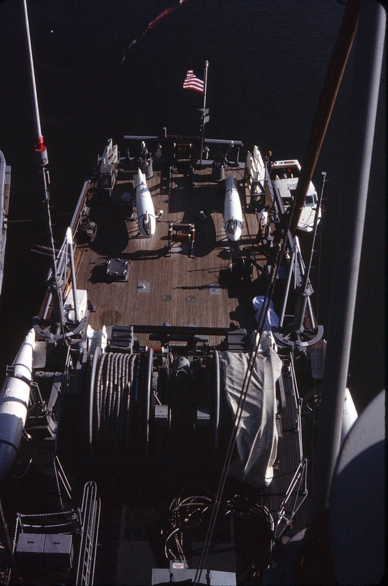
21 minutes ago, Shotlocker said:
GB,
Nice looking vessel you've built! I've also not heard of an MSB even though I was a radioman operator onboard three different
MSO's on the east coast. One comment about the cable on the reel - the cables on board our ships all had segmented floats on
them. The photo is the stern of the USS Alacrity, 1969, as an example. Sure don't know if those river boats had them tho'.
Gary
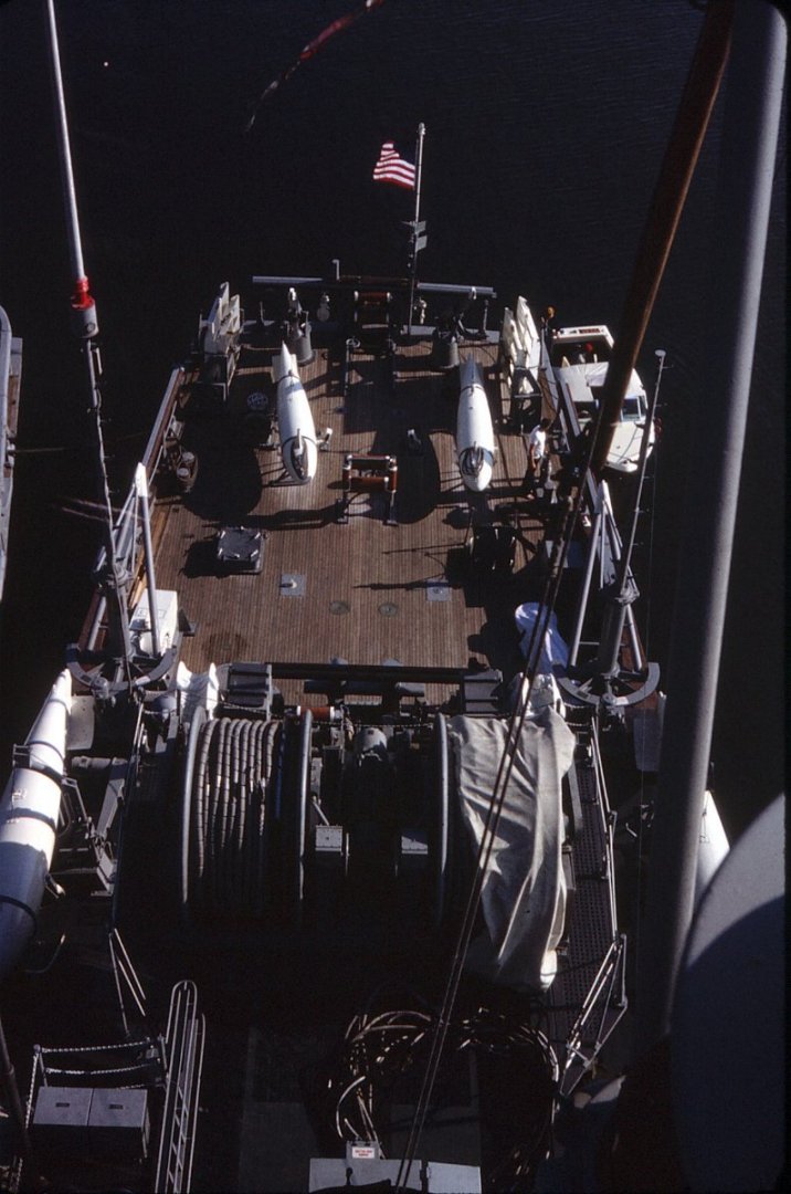
Thanks Shotlocker! I haven't seen the segmented floats before. In the photos I've seen of the MSBs, the cables look smooth🤔...
-
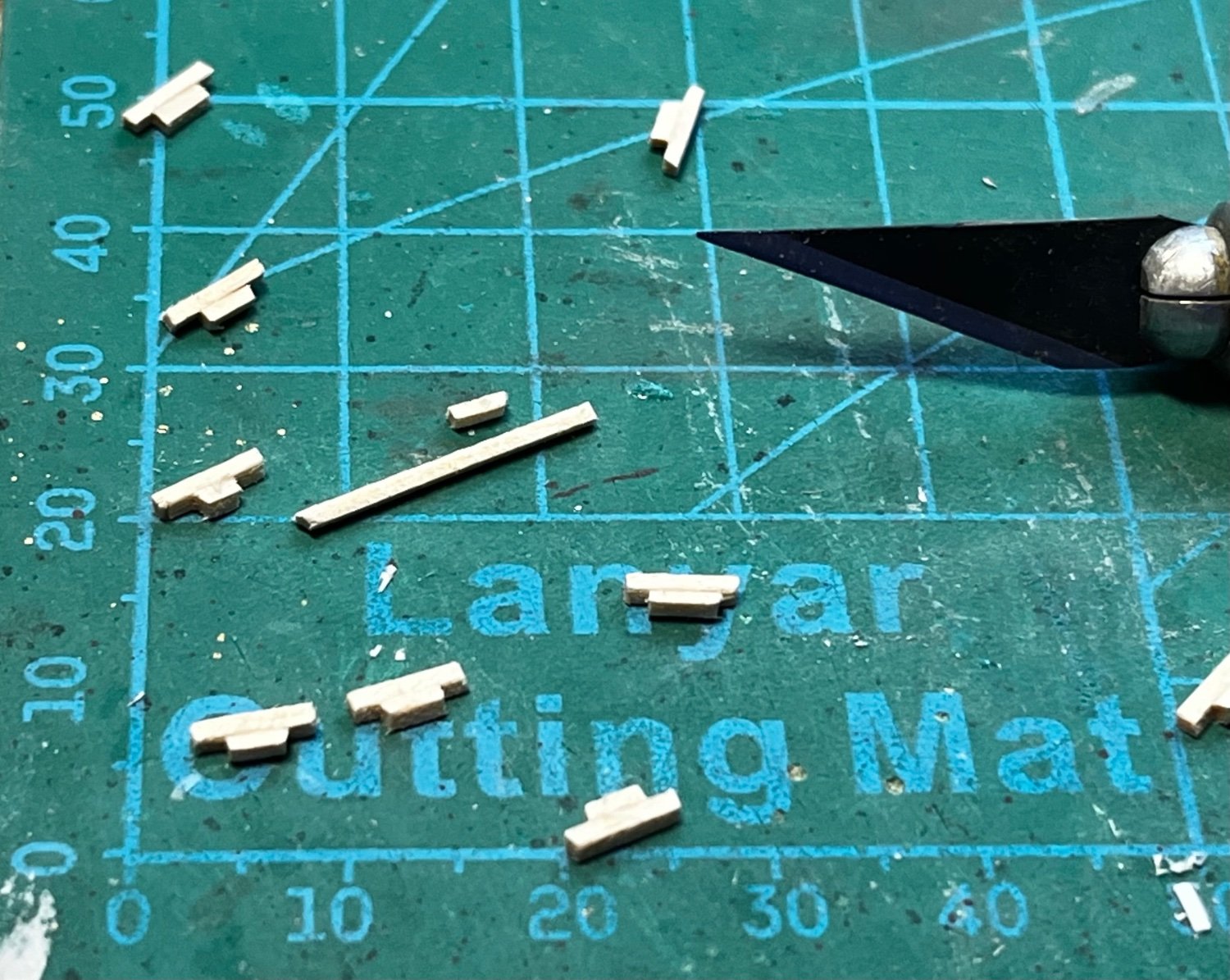
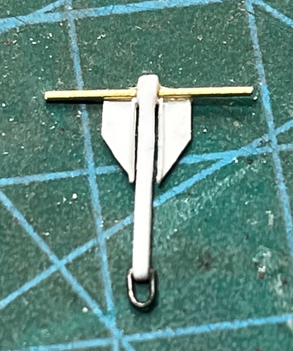
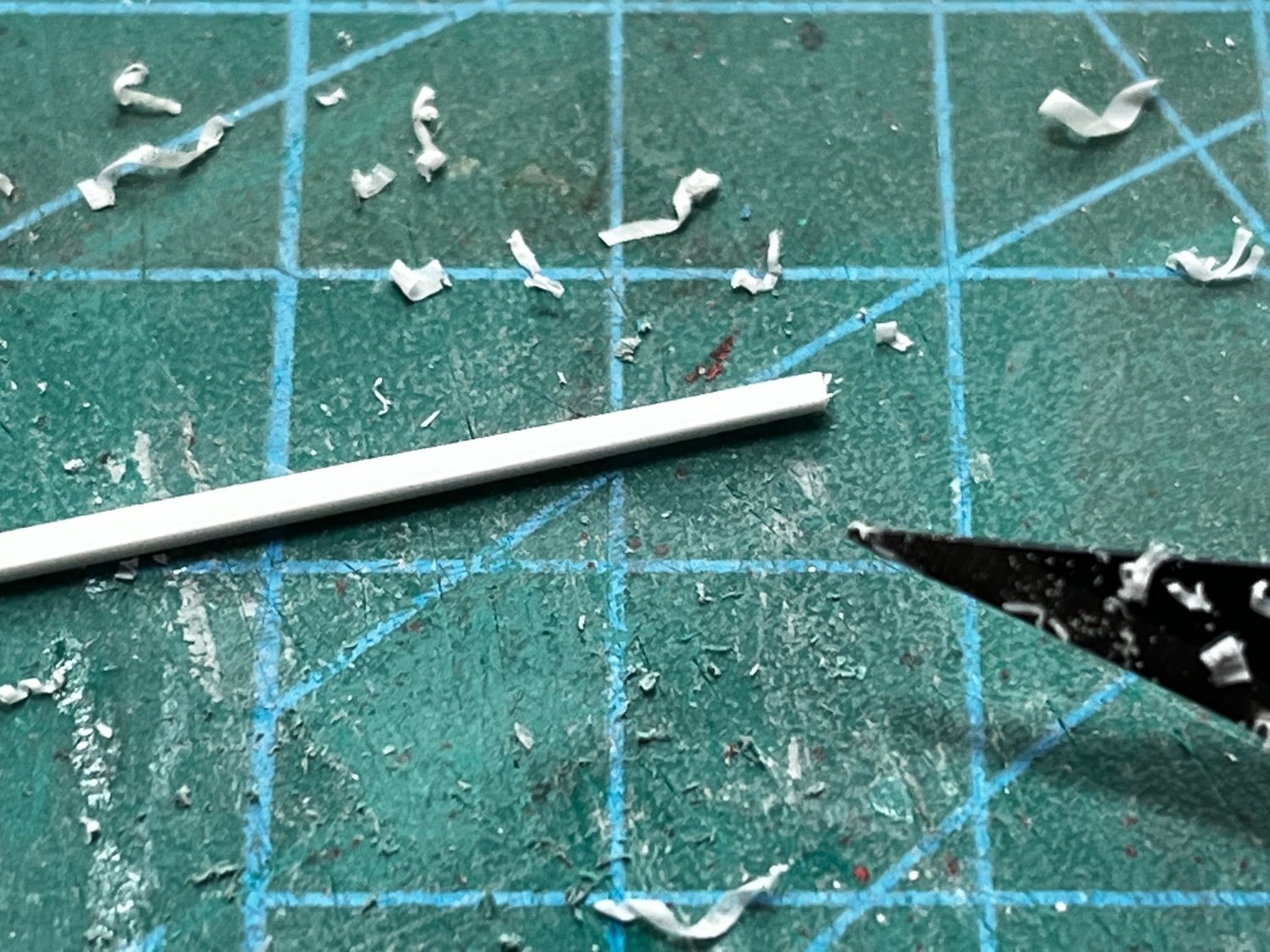
I thought I'd weigh-in on anchors 😁. I really couldn't find any after-market parts that would be both the proper size and type. The US Navy boat anchors appear to have been (are) a fluke style. Anyway, experimenting with wire, plastic strip, brass rod, and styrene sheet (the thickness of a thin sheet of paper), I got the results I wanted.
Here are most of the parts and tools (not counting very thin plastic glue and cyanoacrylate):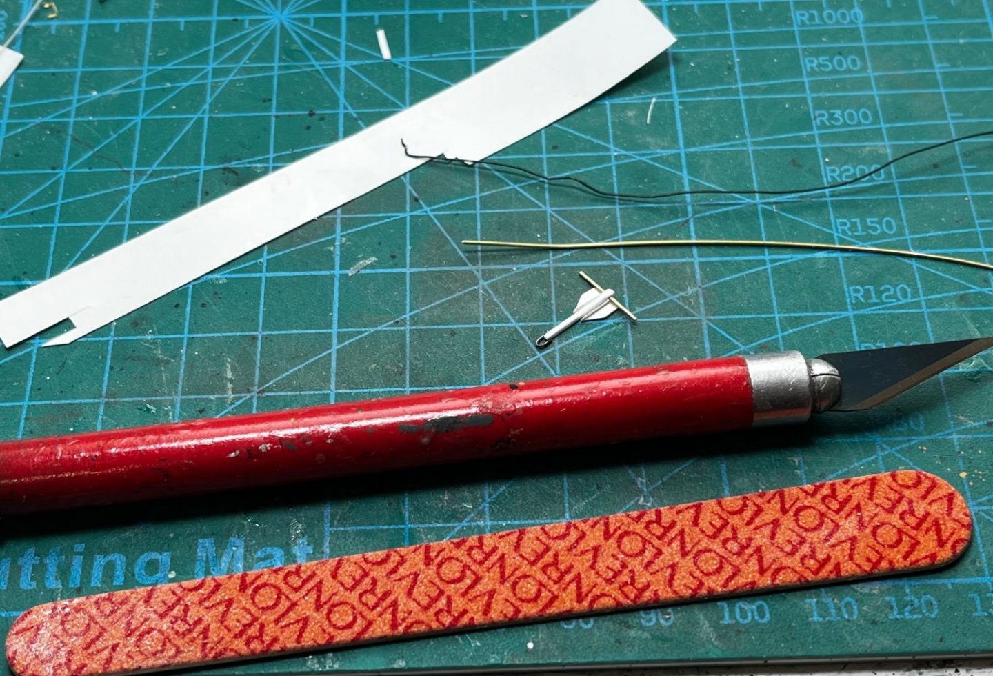
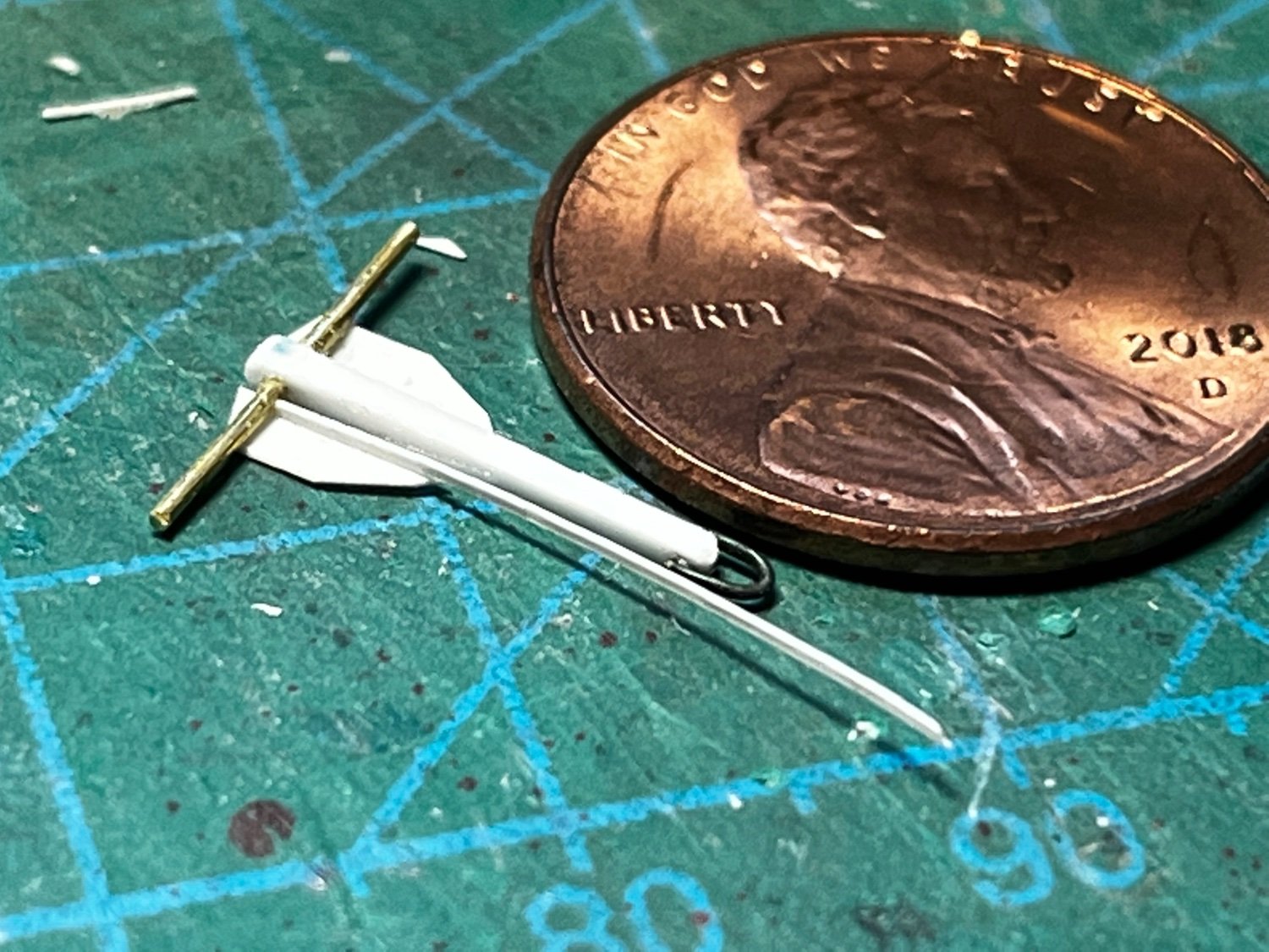
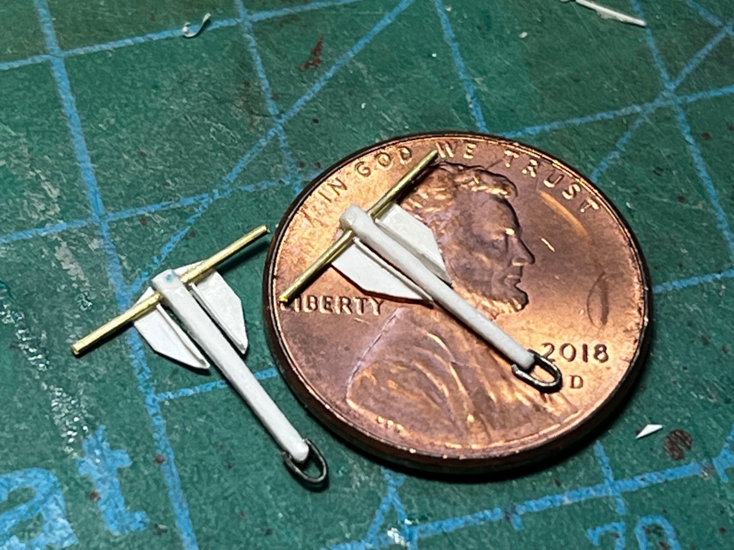
Here's a finished anchor:

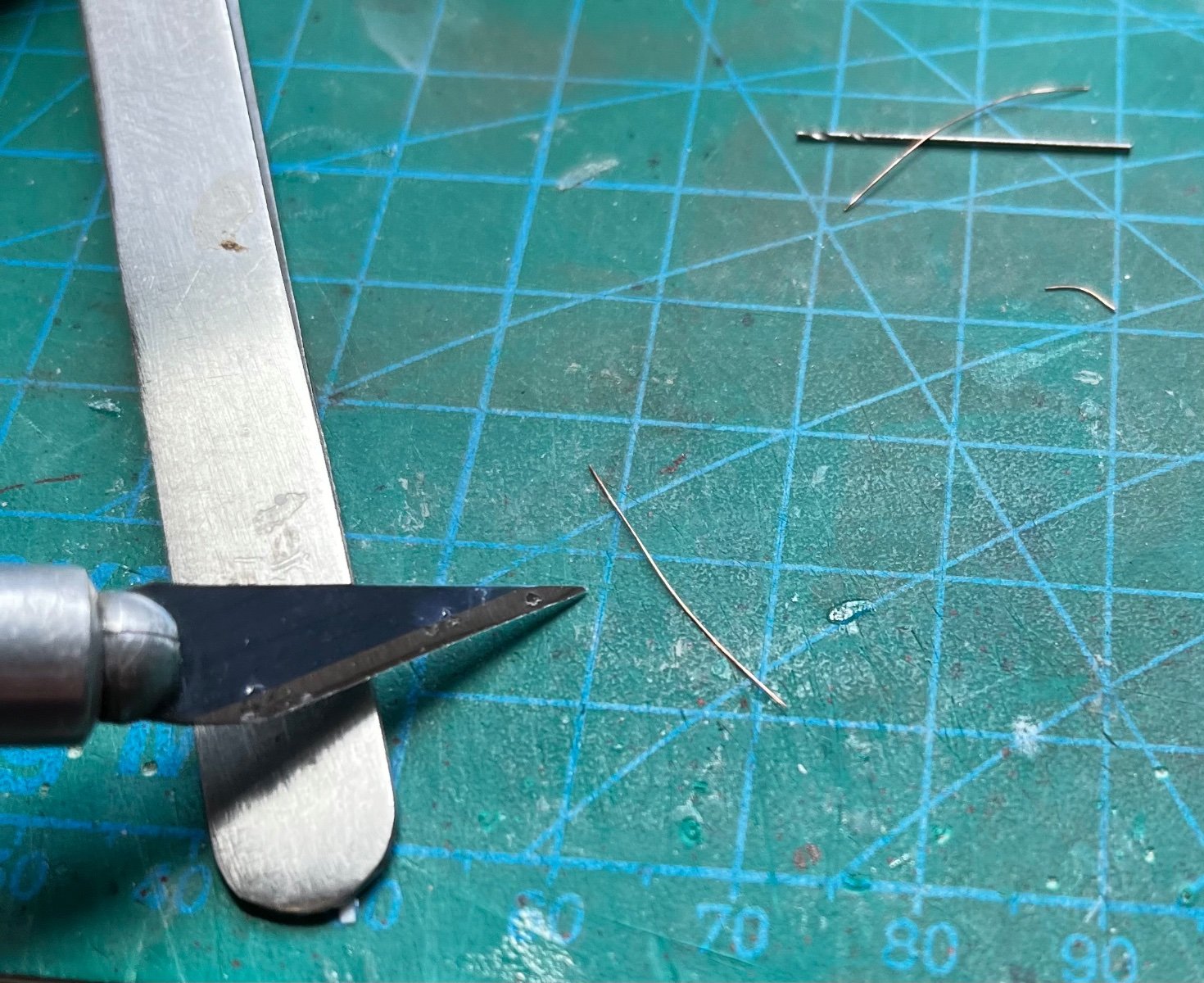
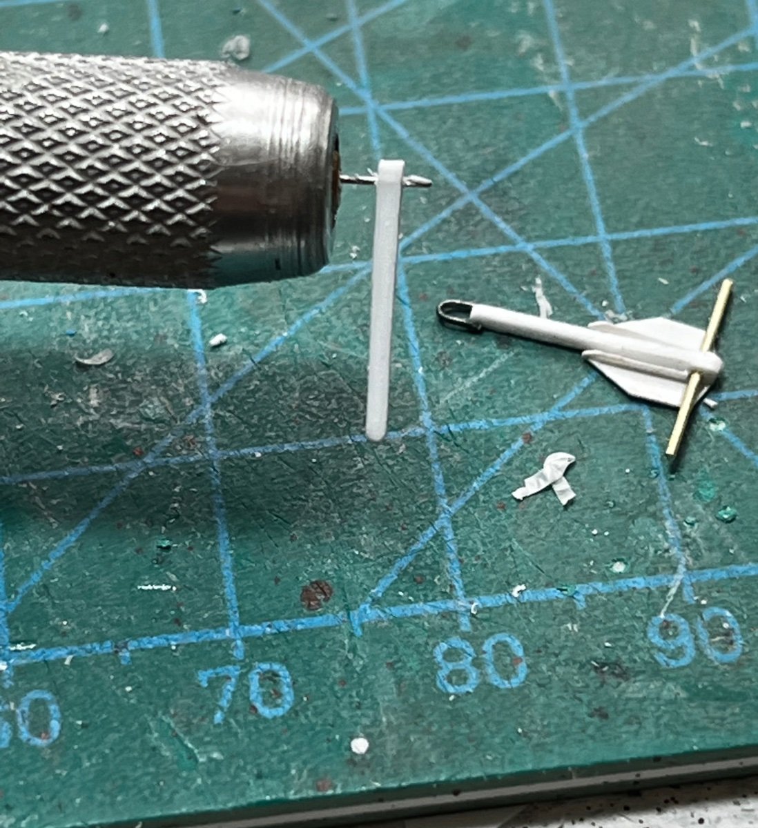
I started by tapering a small square styrene strip by shaving it with a hobby knife...

Then I used wire for the head ring, and brass rod for the stock...
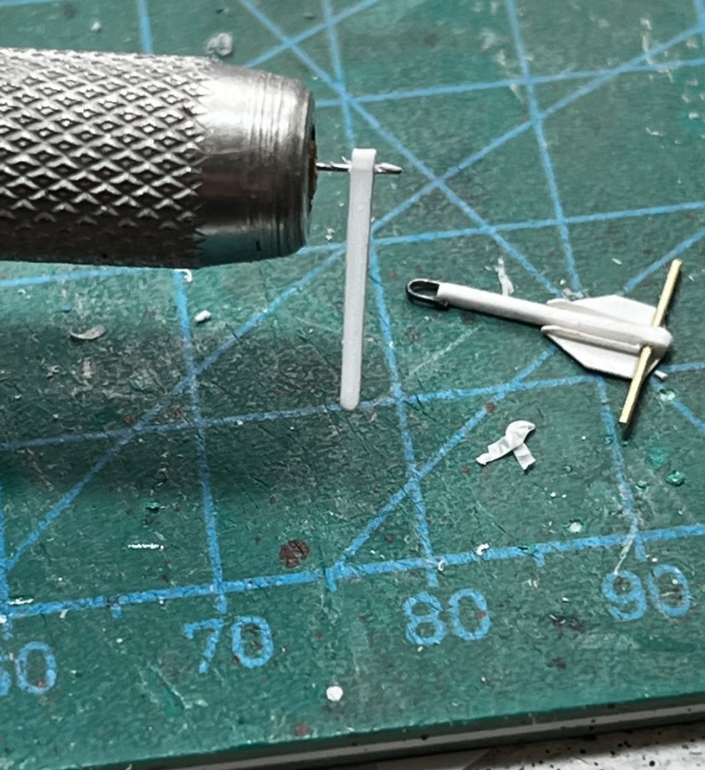
Plastic sheet made the flukes...
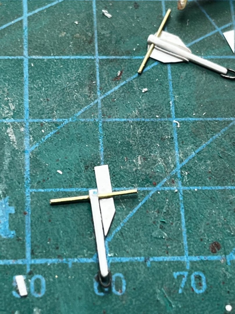
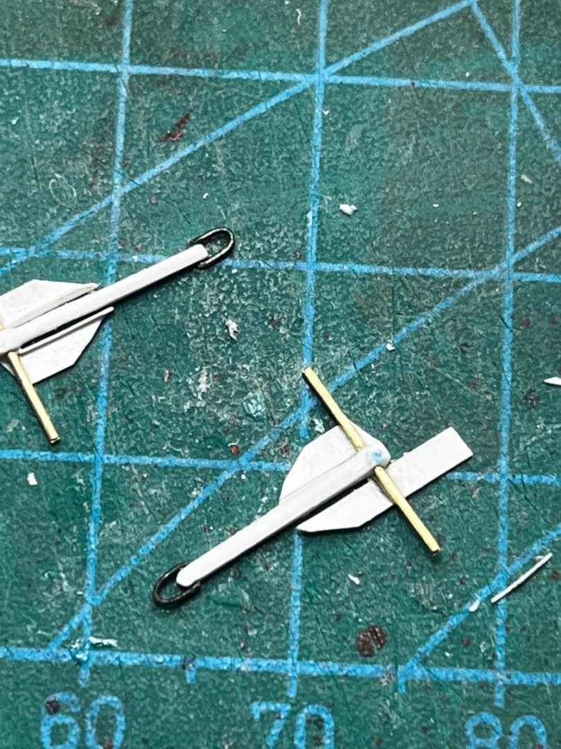
Little slivers of plastic sheet were needed to finish the flukes...
Anchors Away!

-
Thanks for the comments on the WIS (Whatever-It-Is)😃. I can't tell from the photos. Although I used an old "telegraph" part to represent the WIS, the real WIS looks more like a large, perpendicular tube in a cradle as seen in the color photos at https://www.minedivision112.com/early-history/ Maybe it is a binnacle. Anyway, I will probably change my WIS after I try to study it more... Anybody's thoughts would be greatly appreciated!
-
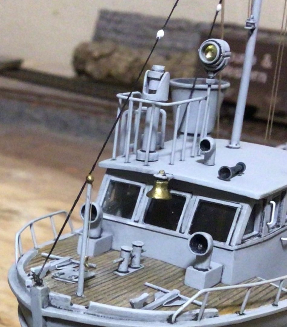
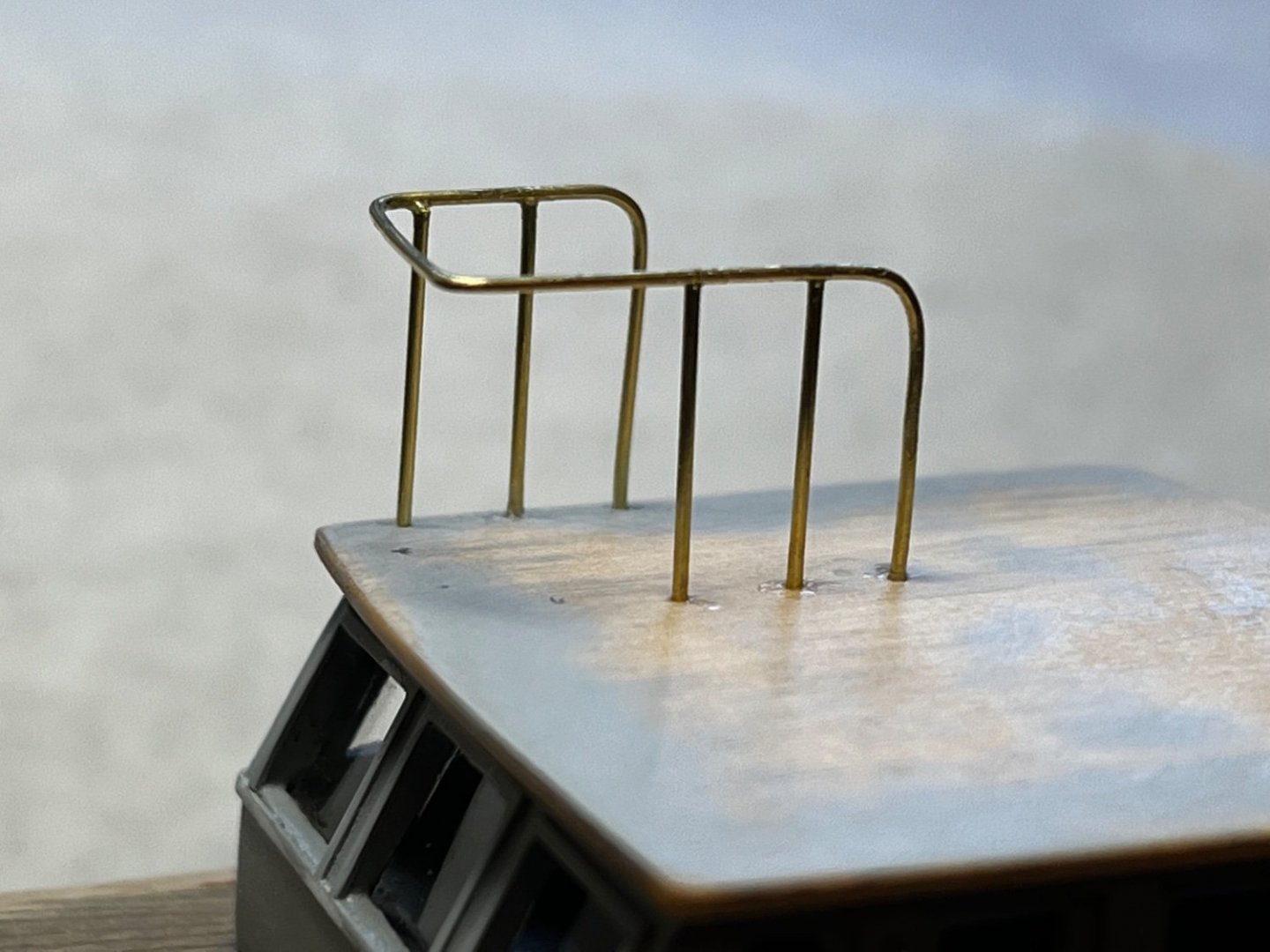
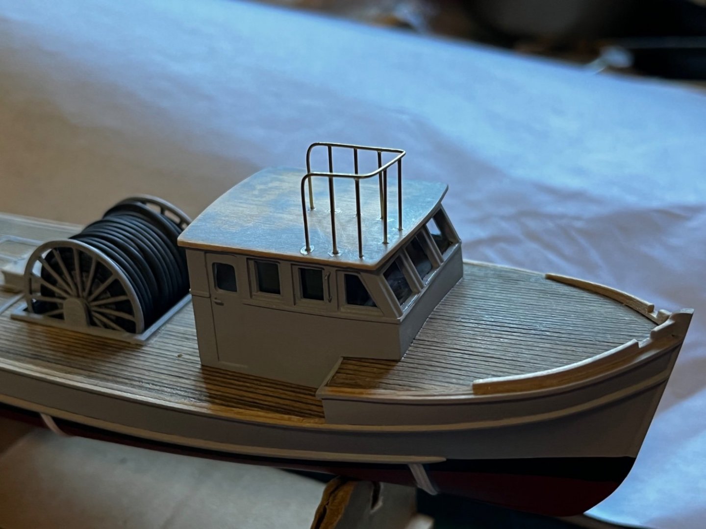
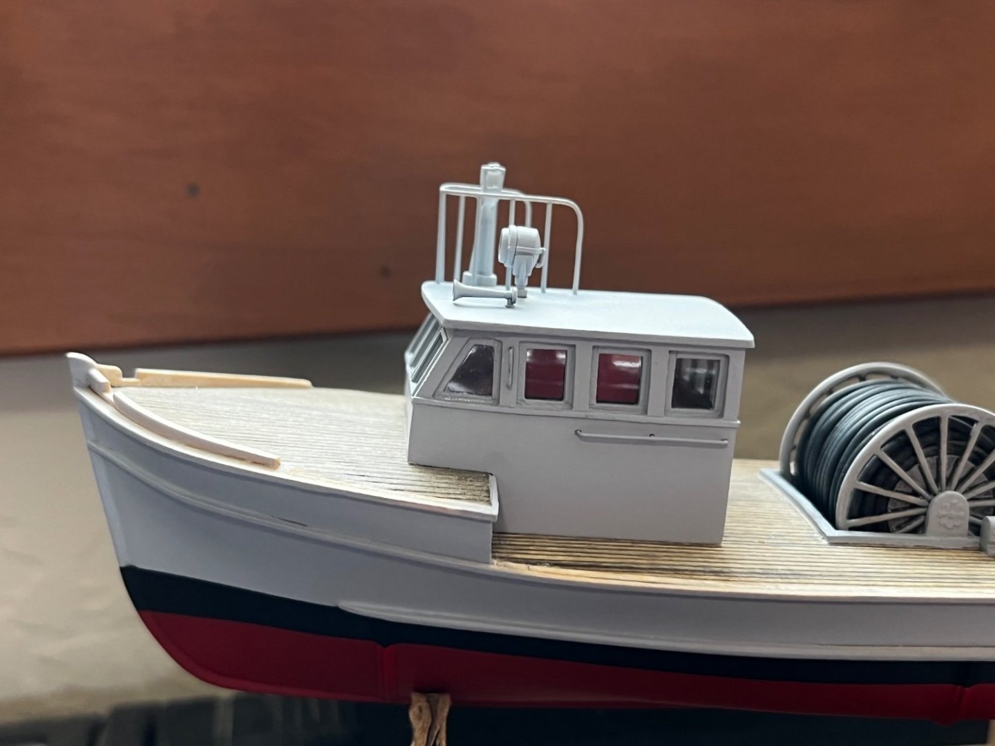
The pilot house roof has some equipment and railing. I decided to make the railing out of small brass rod. The majority was bent (painstakingly) to shape and installed. Then, the supporting stanchions were located and fitted using super glue. Other bits and pieces came from various sources (HO scale diesel horn; 1/35 scale Panzer 3 spotlight; and "what-ever-it-is" from the Lindberg lightship model). They all represent roof items seen in photos of the real boats, in both size and location. I just don't know what the "what-ever-it-is" is on the real boat...
-
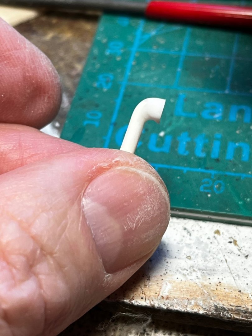
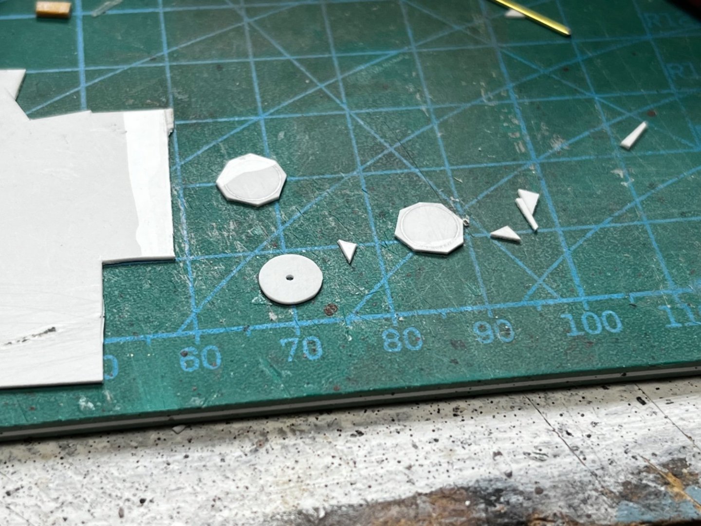
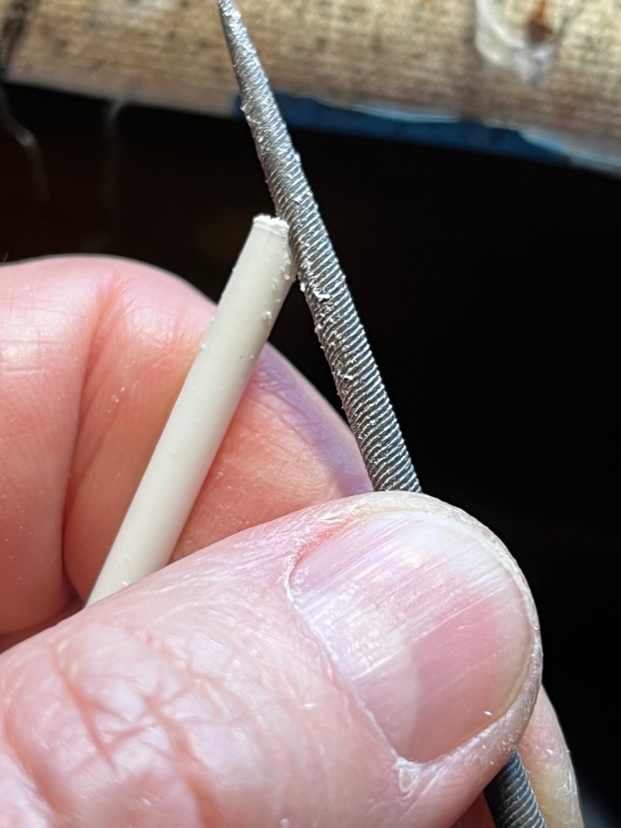
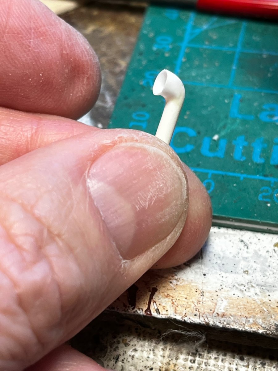
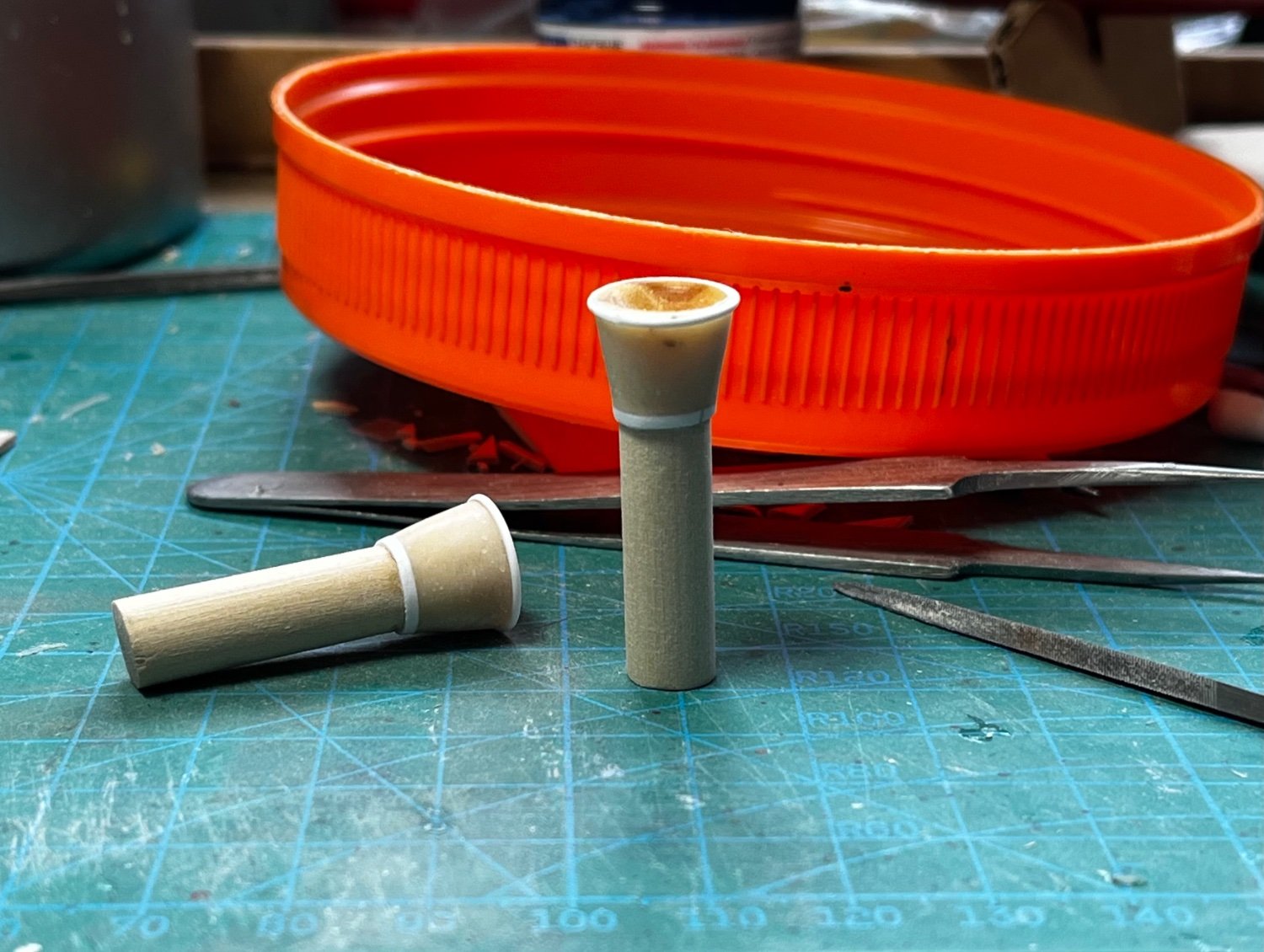
One of the little details needed are air vents. They were small on the real boat, and really tiny in 1/96 scale. However, the vents were clearly visible in front of the pilot house, and sat on small dorade boxes. Here's how I made the air vents from styrene tubes...
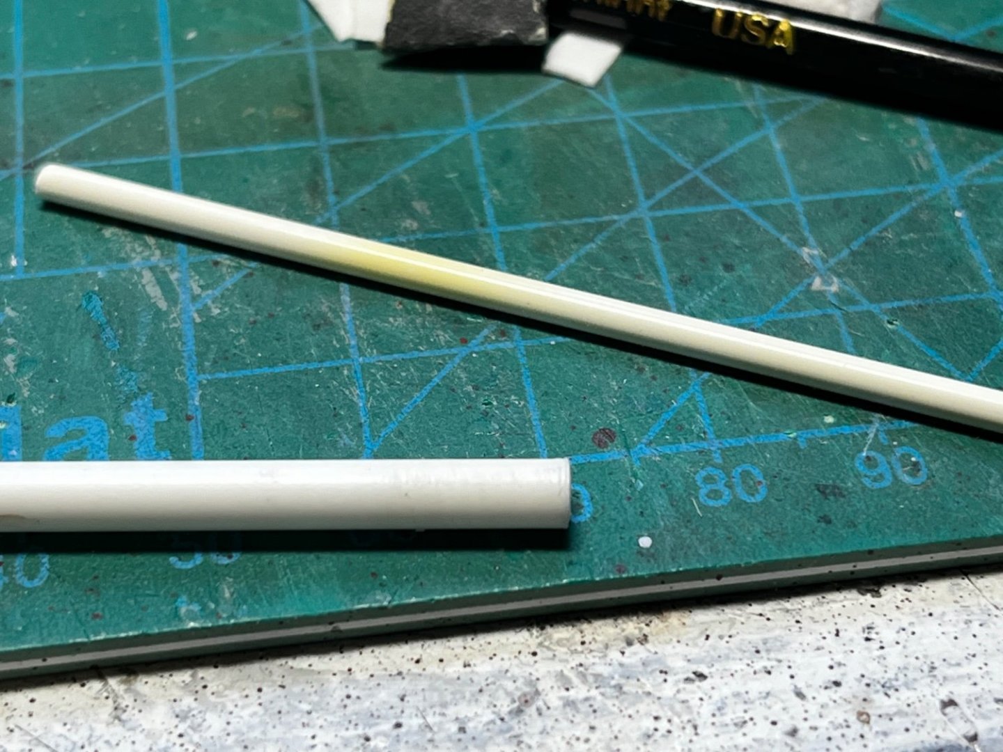
Two sizes were needed to make the flared vent...

Using a round file I formed a half circle notch on one side of the large tube...
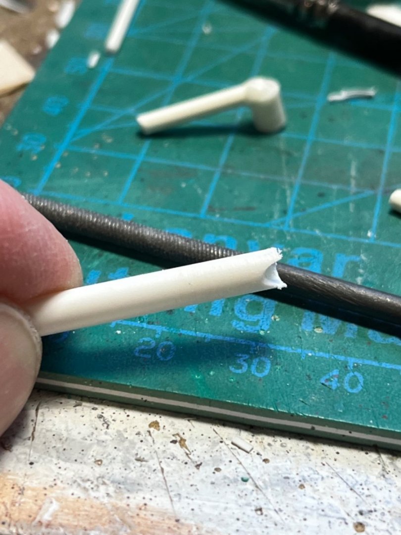
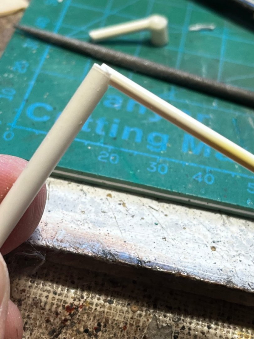
The smaller tube was glued into the notch at a right angle. Then, filler is used to build-up a bulb around the joint...
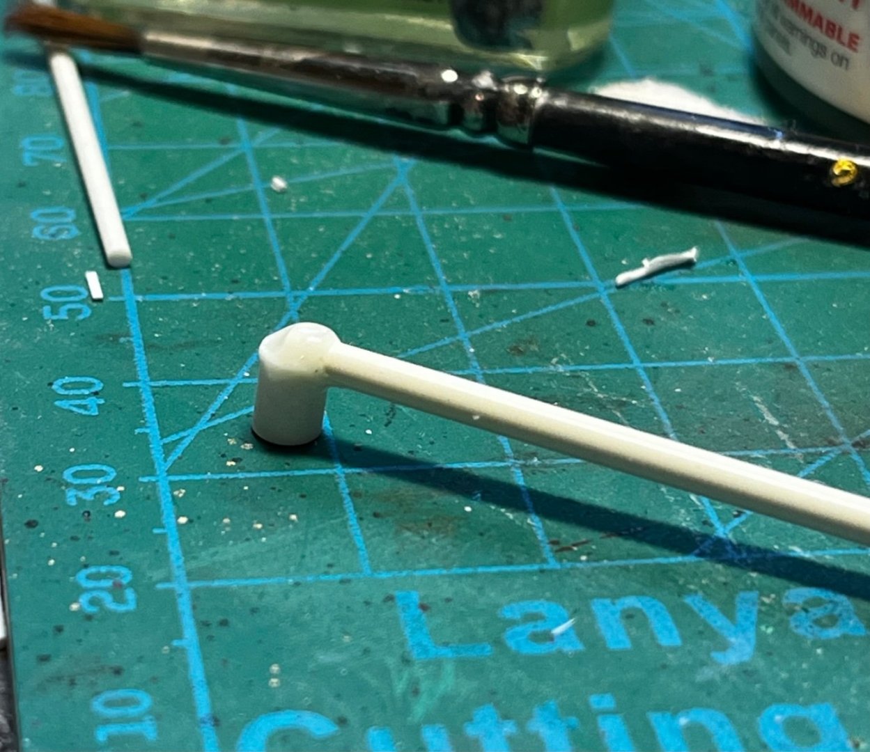
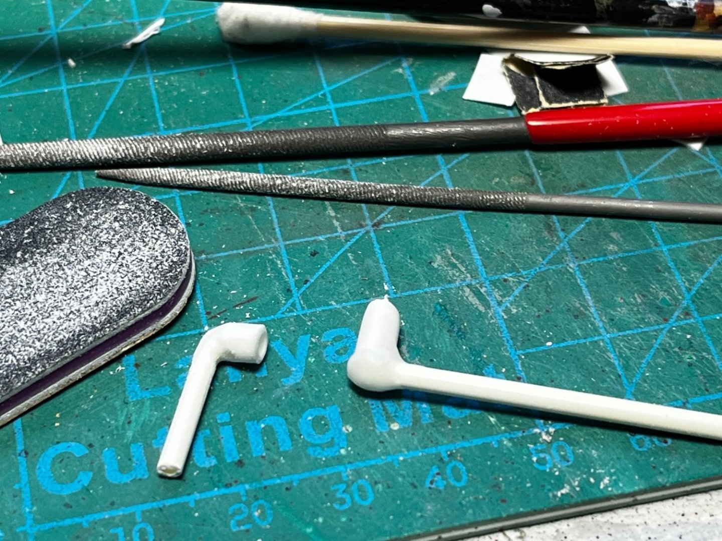
The vent is then filed and sanded to it's final shape...

- Paul Le Wol, Glen McGuire, lmagna and 10 others
-
9
-
4
-
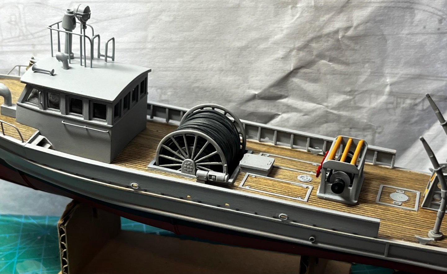
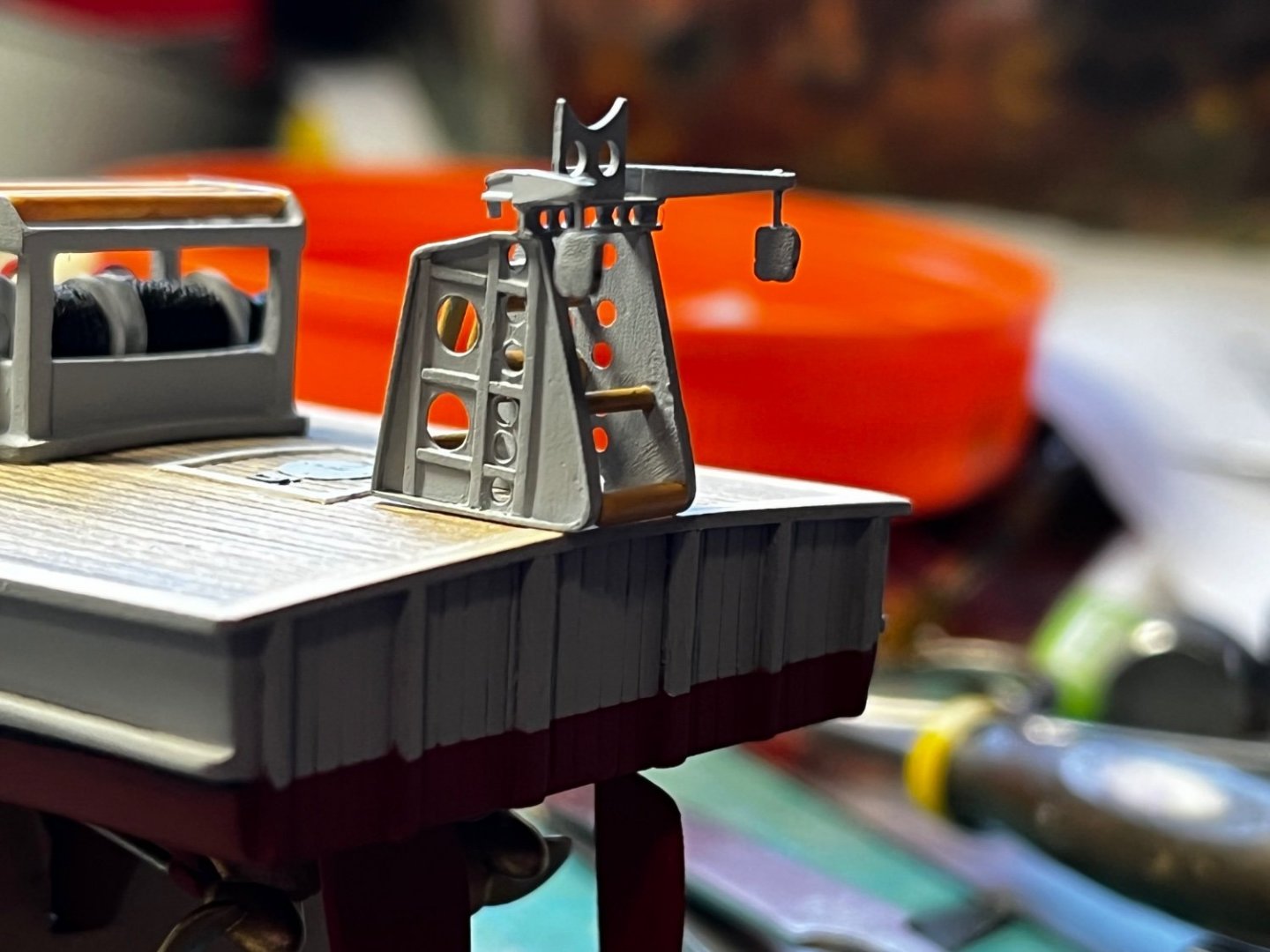
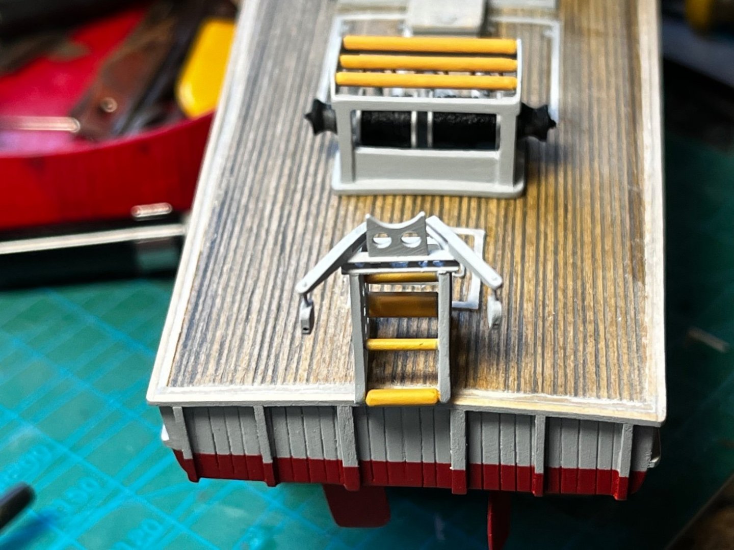
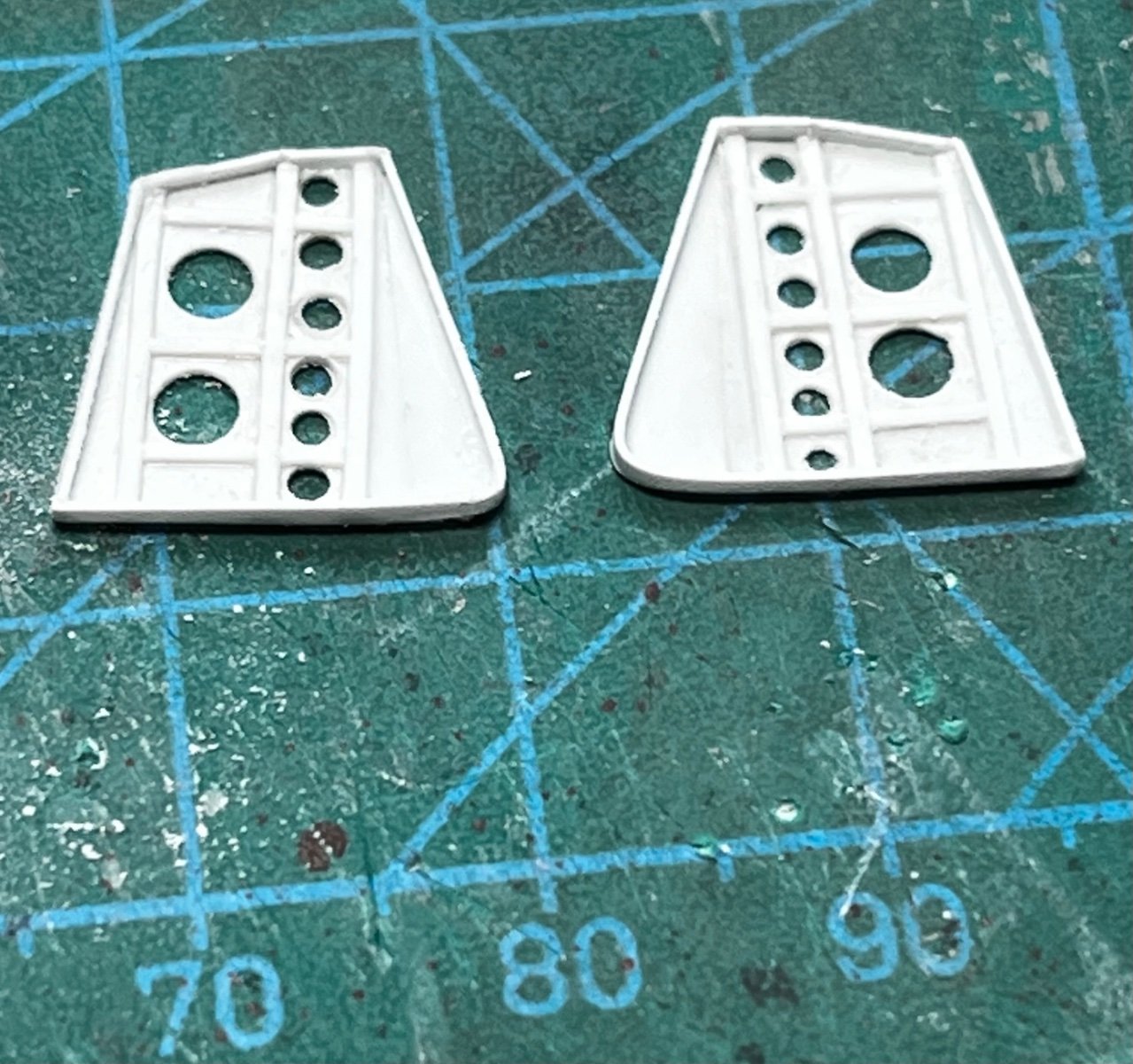
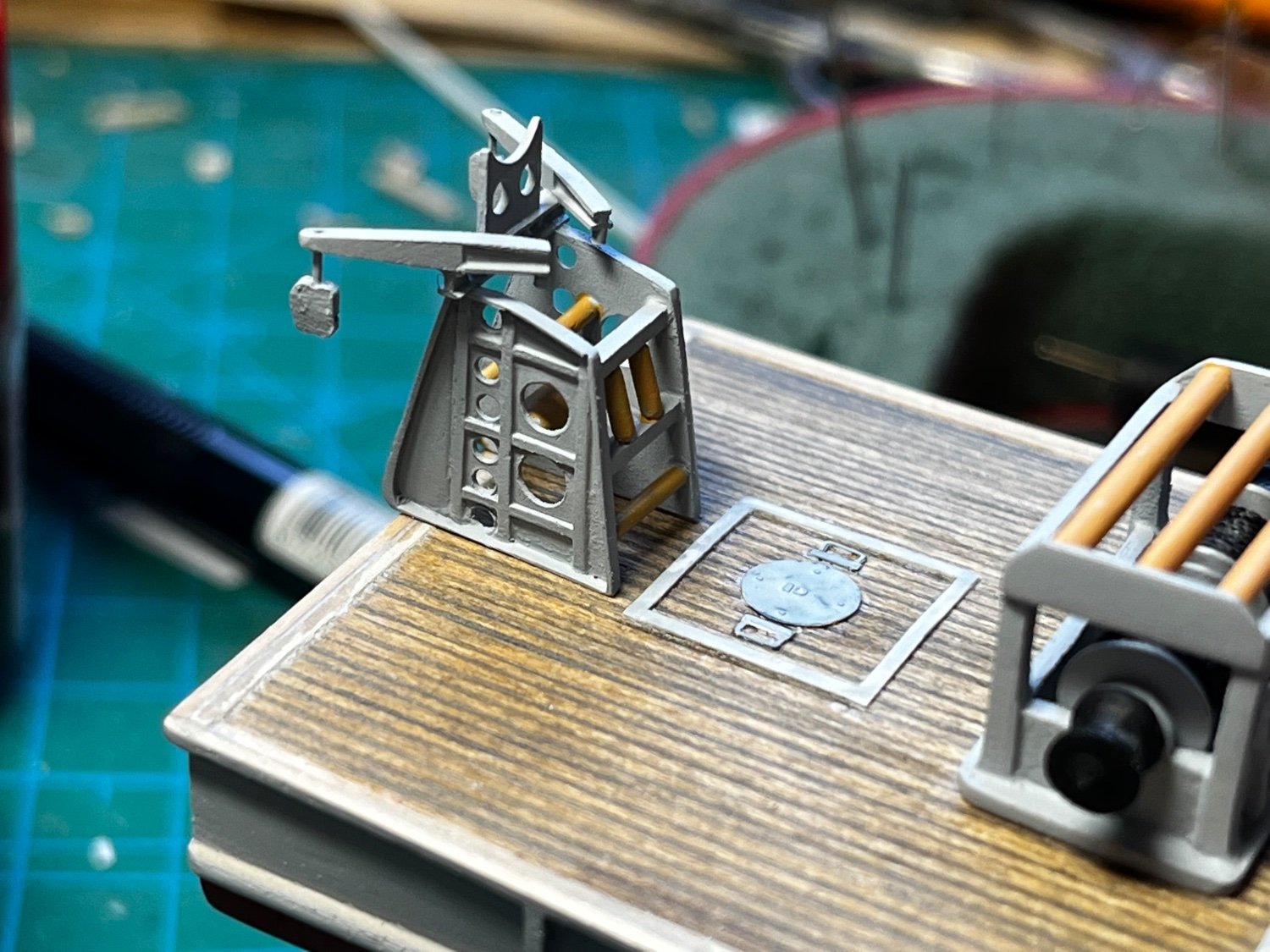
At the stern end of the boat sits a framework of rollers and pulleys that are used to play-out the cables. My photos show these had different configurations, probably due to modifications or improvements made over time. However the basic framework looks the same. With the small scale I'm working in, and because this structure is relatively small, complex, and made of metal, I decided to make it out of styrene. The following photos show a little of the construction and how it will appear on the boat, although it is not yet glued-on. I also have to touch-up the paint a little....


-
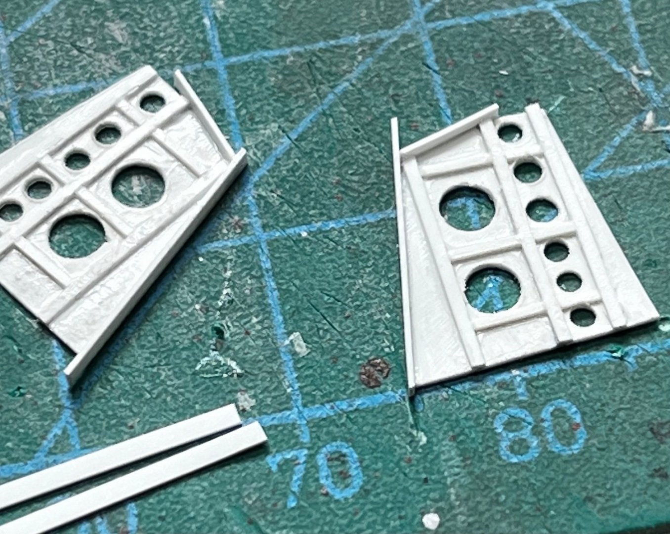
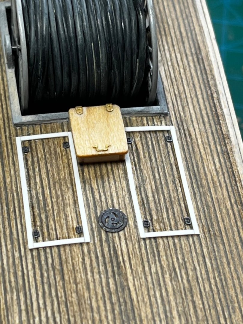
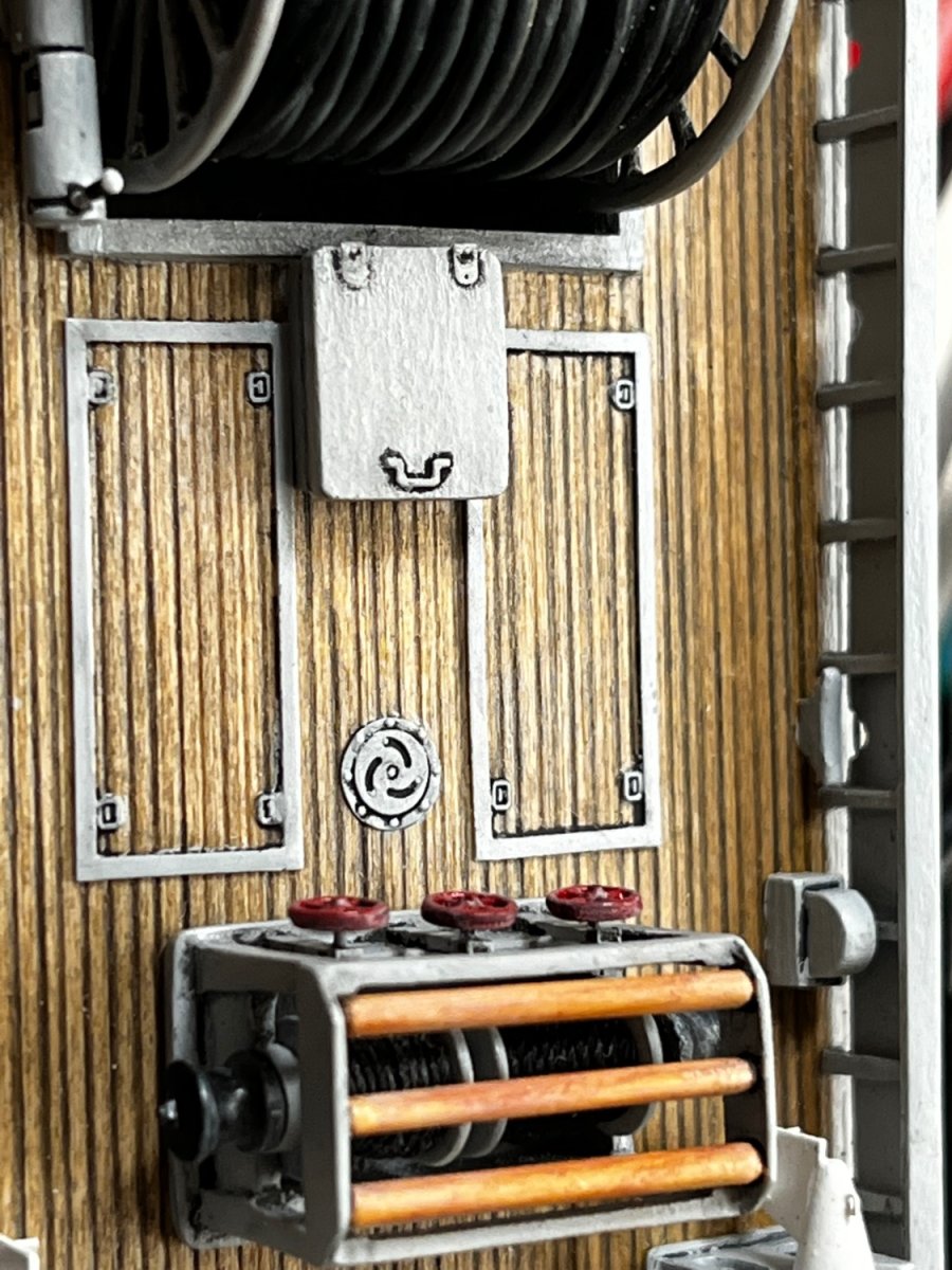
So, the detail work begins with hatches on the main deck. Plastic strip and my endless photo-etch supply are called to service for the panels flush to the deck, etc. Photo-etch and basswood bits make the raised hatch and combings.
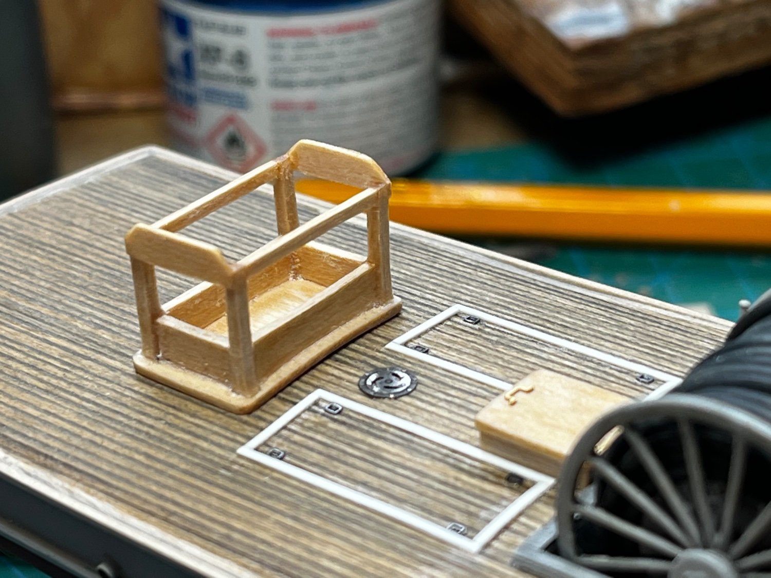
Basswood is also used for the small cable reel station. Again, careful study of photos from the internet provide a basis for construction.

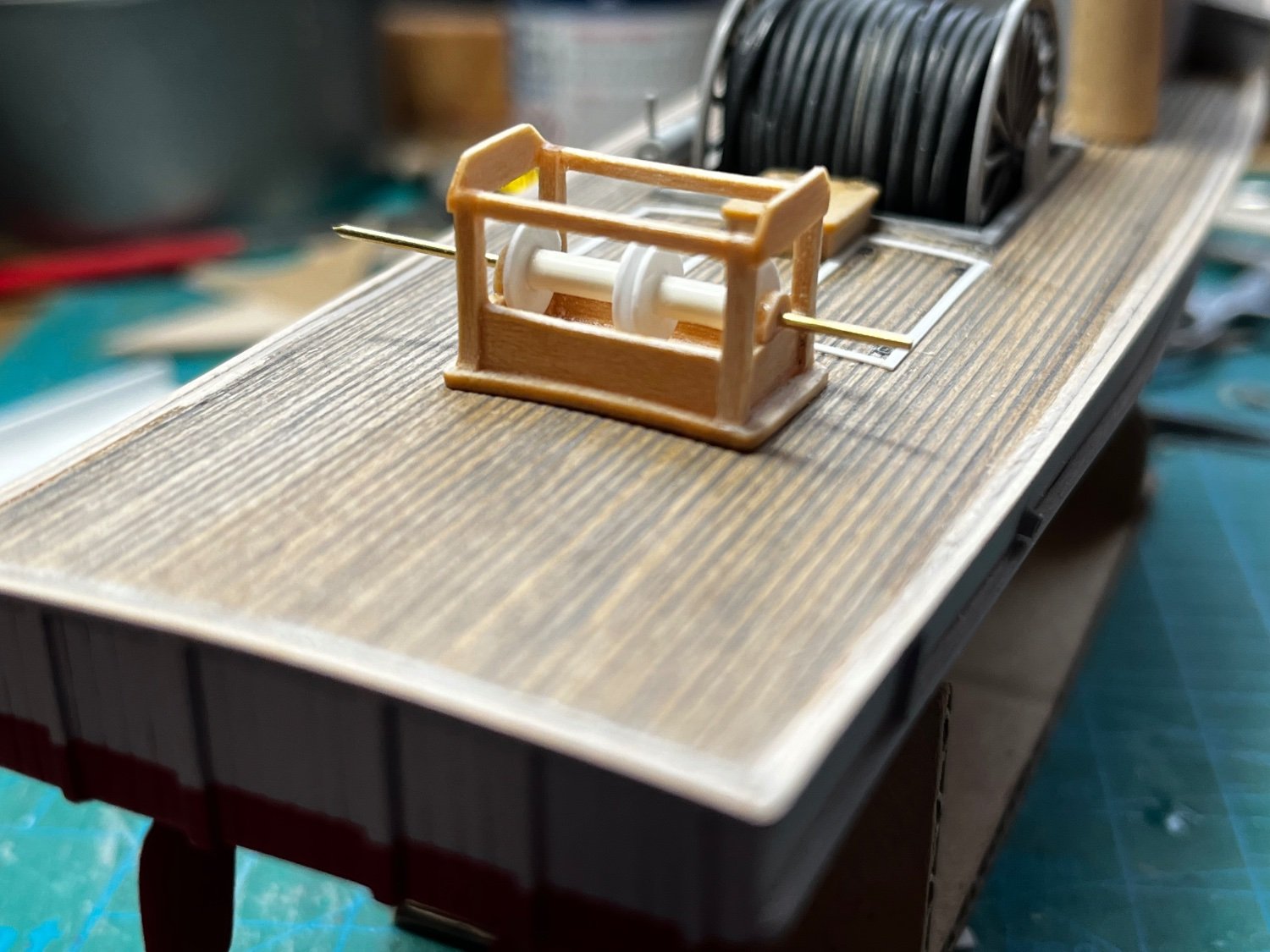
The framework for the small cable reel station....

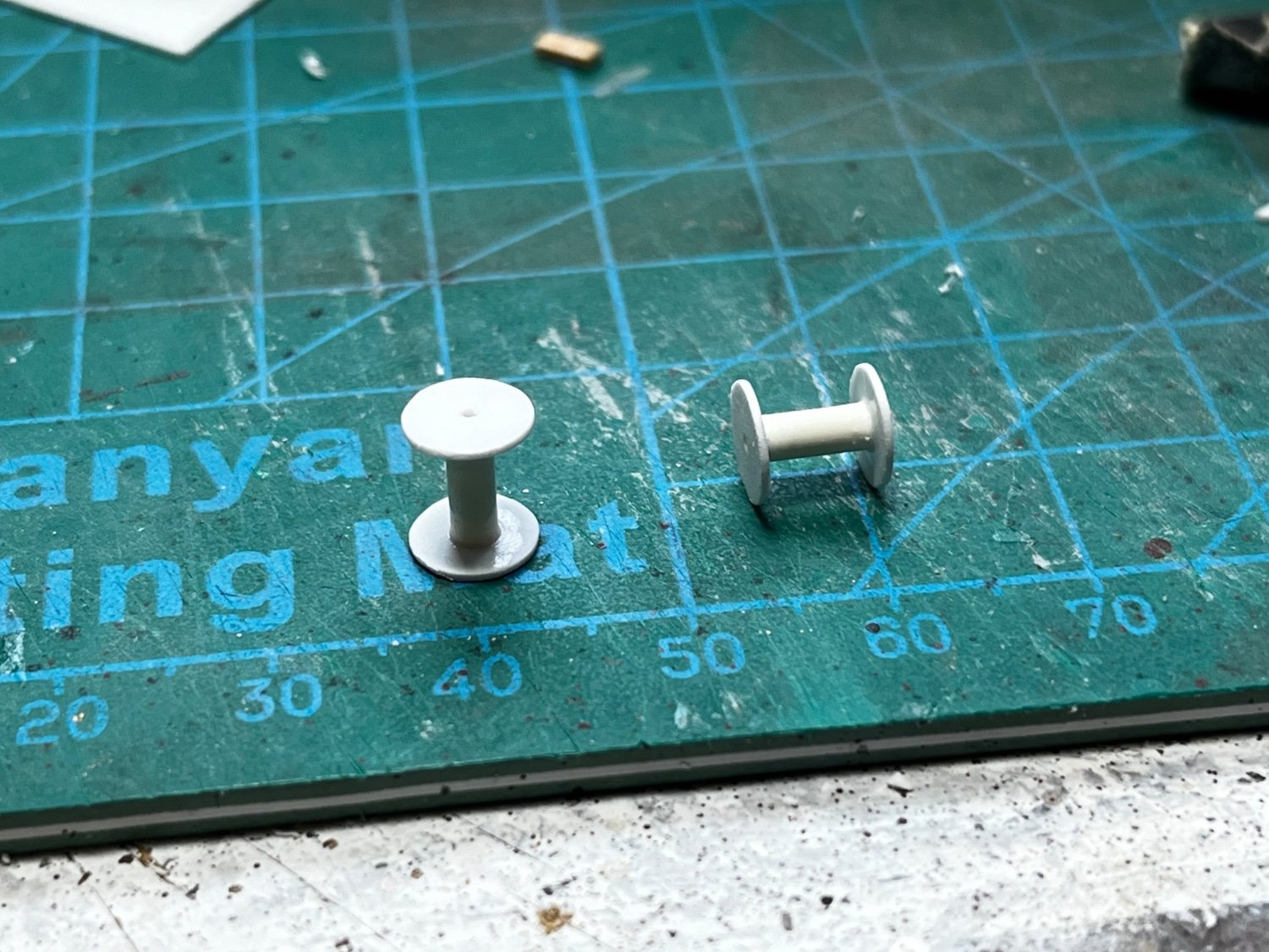
Cable reels under construction from plastic sheet and tubing...
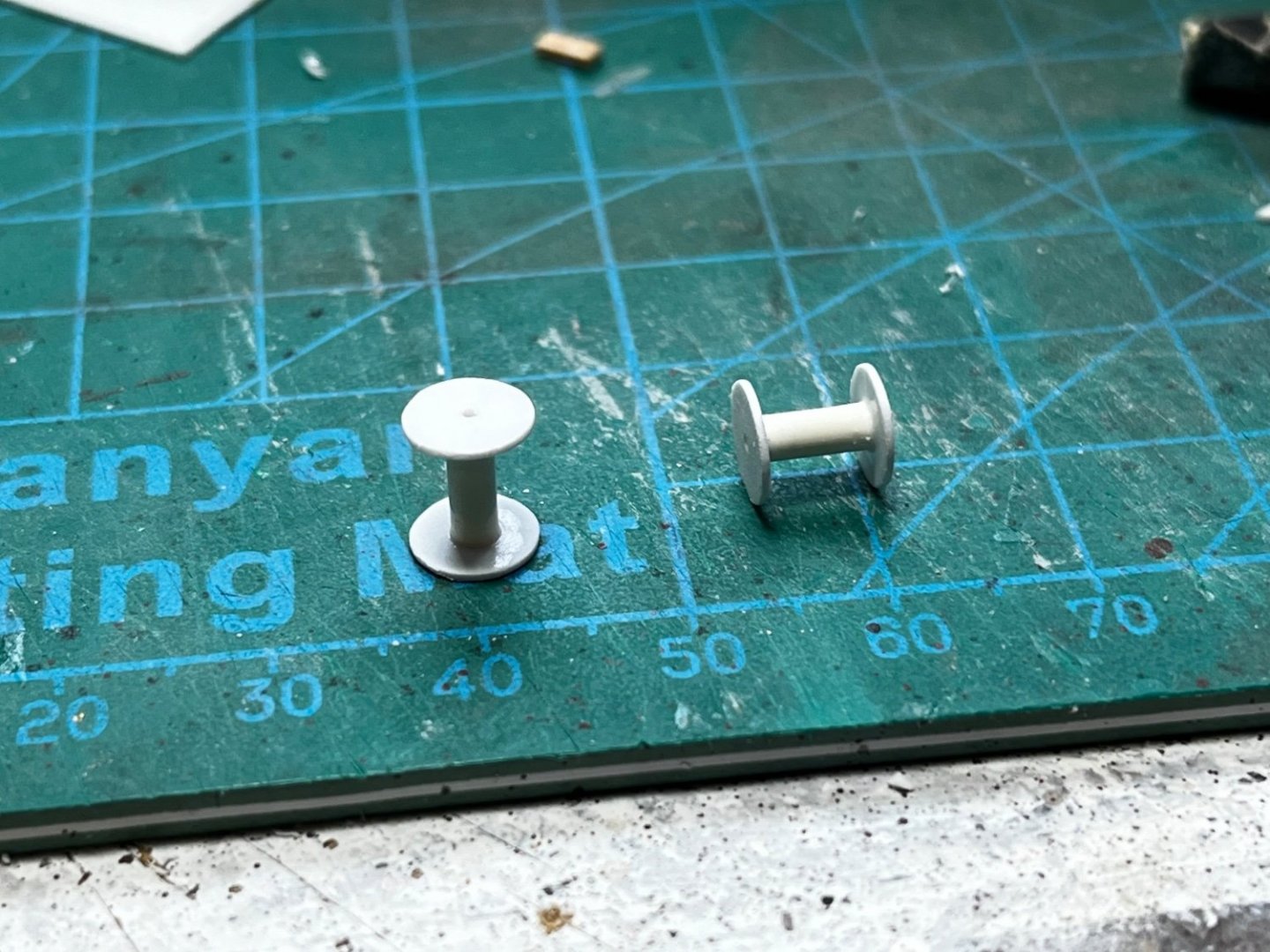

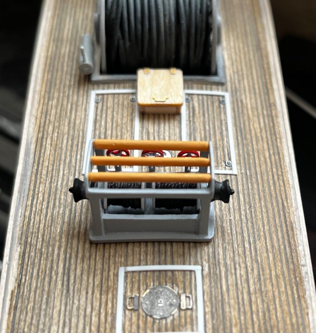
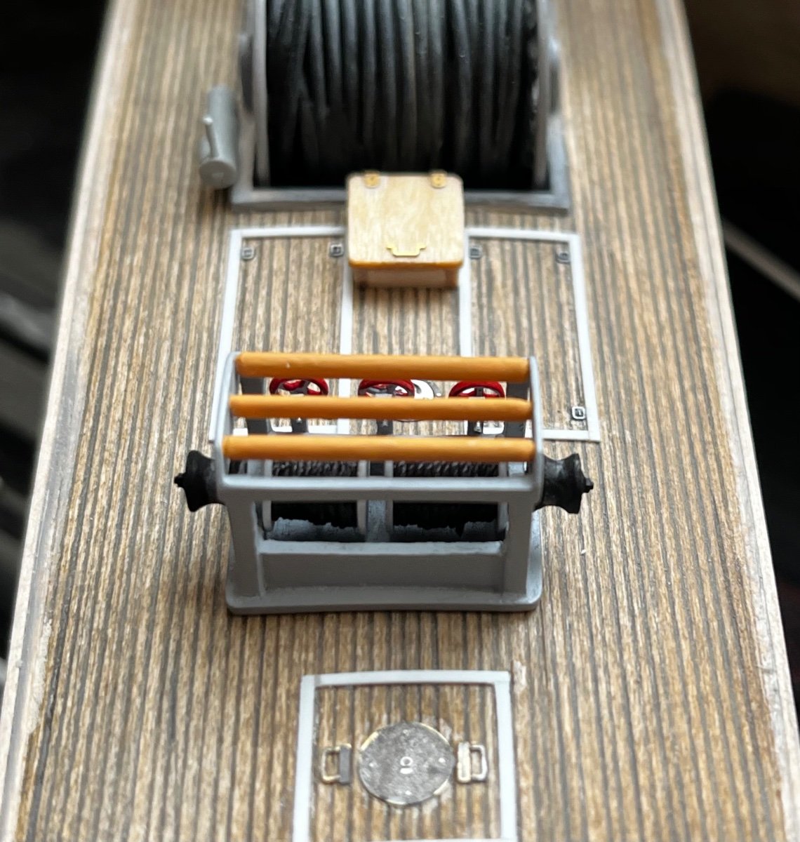
The final product; the tan tubes on top of the structure are rollers...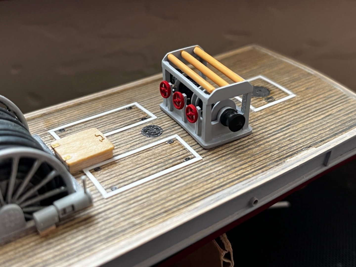
The cable station is not yet glued in place, so it looks a little off center in this photo...
-
1 hour ago, Roger Pellett said:
Very nice work on an interesting subject.
Unfortunately mine warfare seems to be one of those things forgotten about by our navy until there is a crisis. The fleet of minesweepers from the 1950’s was built in response to the Navy being stymied by mines sowed by North Korea off Wonson during the Korean War. I spent the summer of 1964 as a Naval Reserve Midshipman aboard a coastal (MSC) and an Ocean Going Minesweeper (MSO) operating in the coastal waters of Japan.
The large reel on the boat that you are modeling held an electric, not an electronic cable for sweeping magnetic mines. The idea was simple; an engine powered a generator that passed a current through the cable towed behind the vessel. The field from the electric current set off the mine- hopefully far enough behind the ship to avoid sinking it. The passage of the “ship” and its supposed size could be mimicked by varying the voltage or current in the cable; I don’t remember which. This was done by varying the speed of the engine powering the generator with a cam that varied the throttle setting. I believe that there were different cams to mock up different situations. When sweeping, the sound of the engines running the generators speeding up and slowing down in the cam driven pattern could be heard throughout the ship.
Roger
Great information! Thanks!
- Canute, Roger Pellett and mtaylor
-
3
-
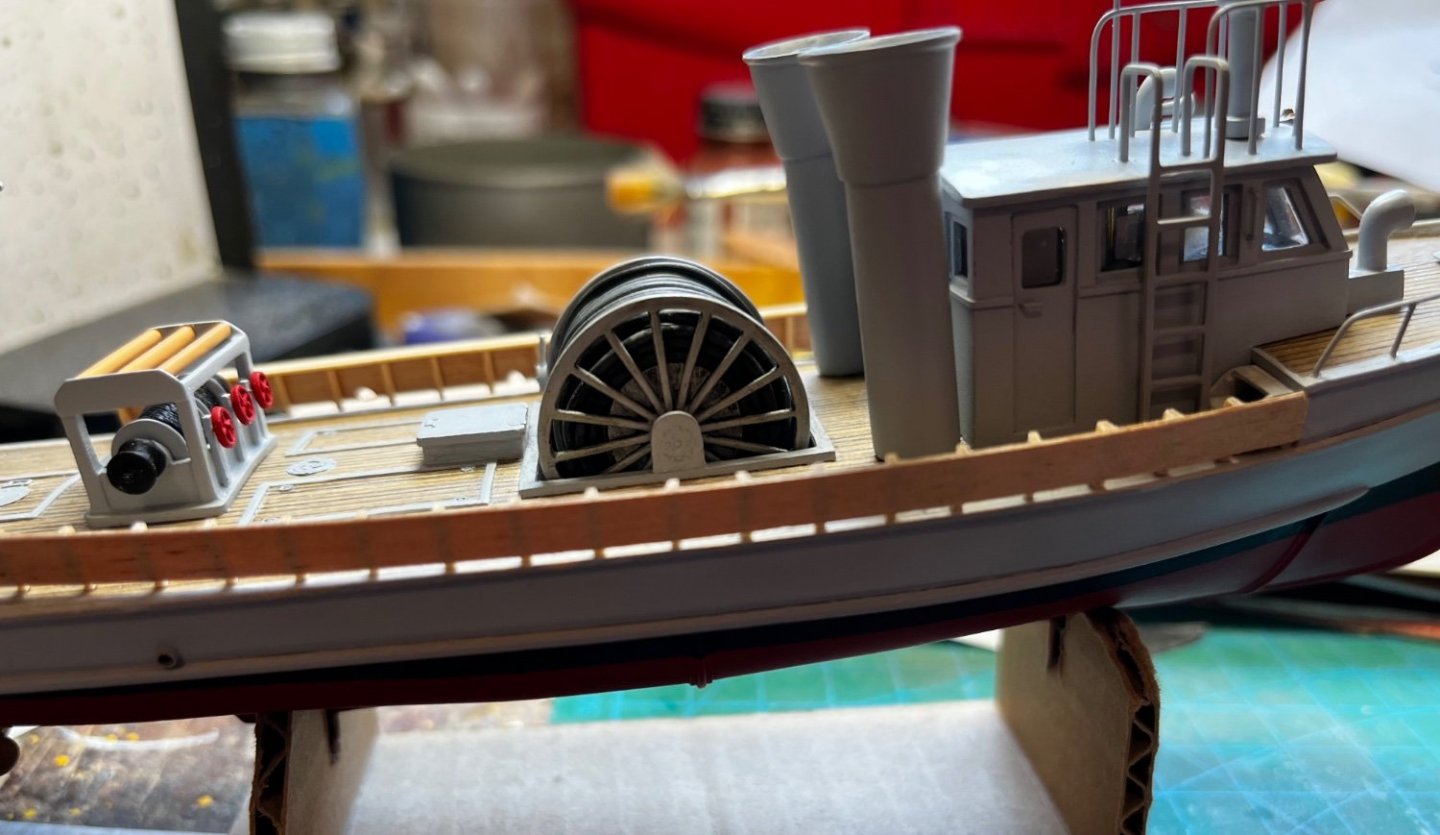
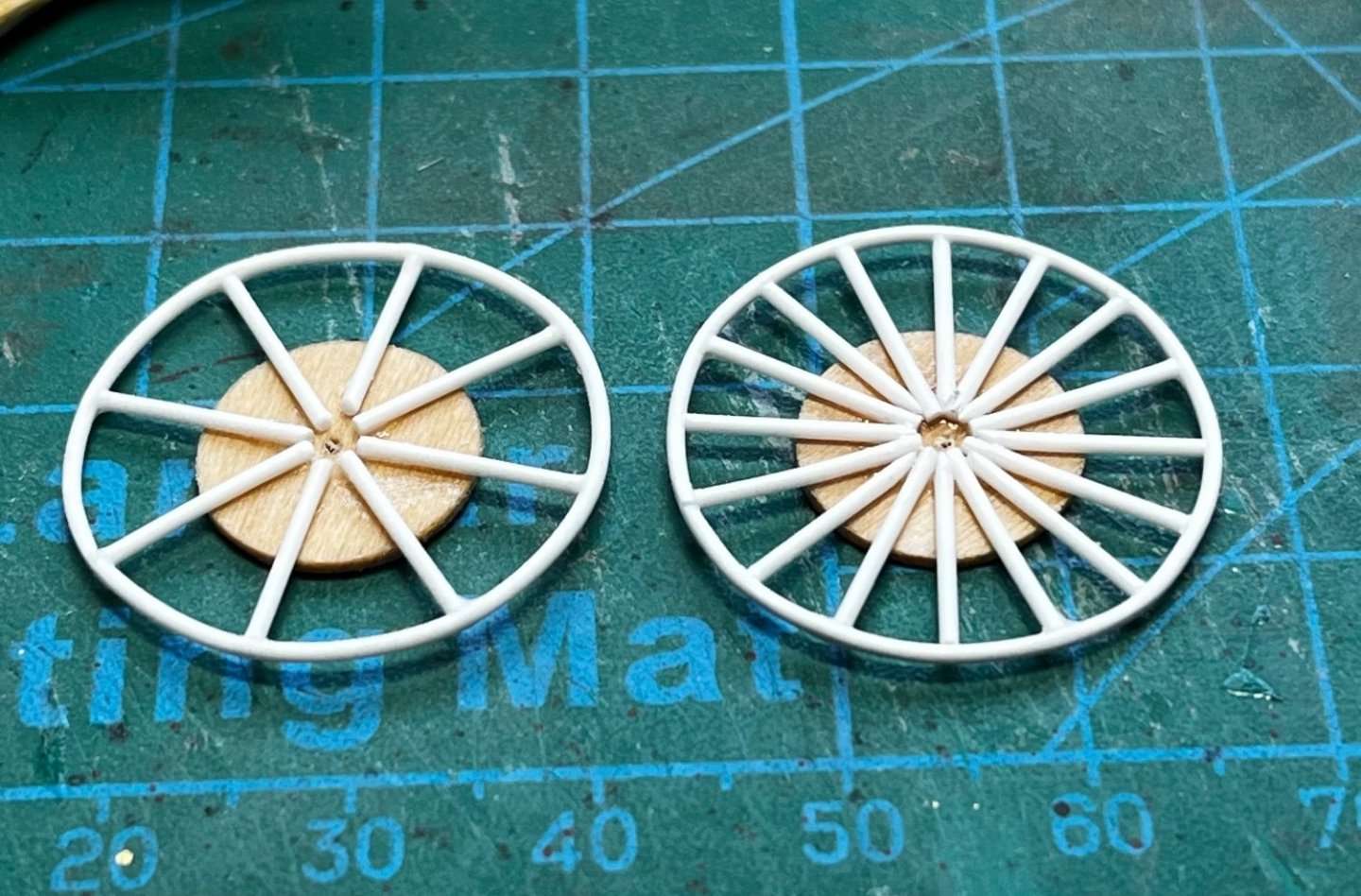
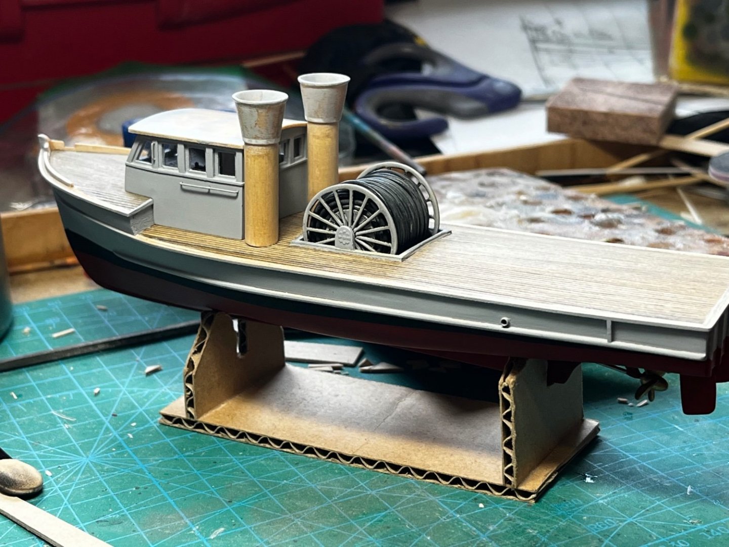
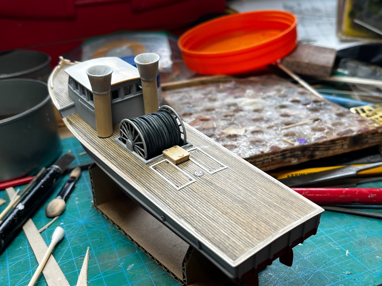
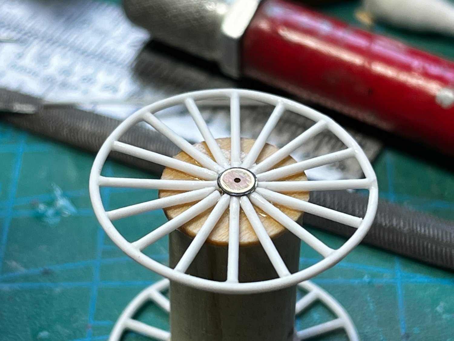
The next big challenge was building the large reel for the electronic mine sweeping cable. I find it difficult to draw or make perfect circles, and that's exactly the shape of the reel! Constriction started with a wood disk cut from the 1/32" basswood sheet. A circle gauge helped me get the disc close. Then, carefully measured spokes for the reel were attached, made from styrene rod. The same rod was used to wraparound the outer edge of the spokes. The result was not perfect, but presentable... . Again, old photo-etch was used for the reel hubs. To represent the smooth cable, I used black insulated copper wire. The reel is mounted on piano wire and can really turn (don't know why; it doesn't have to for the purpose of the model).
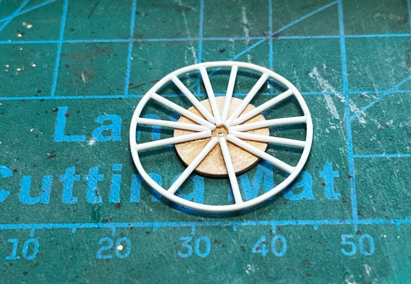
The outer rod was placed after the initial set of eight spokes were attached. The second set of eight spokes were added later...
A wood dowel was used for the core of the reel...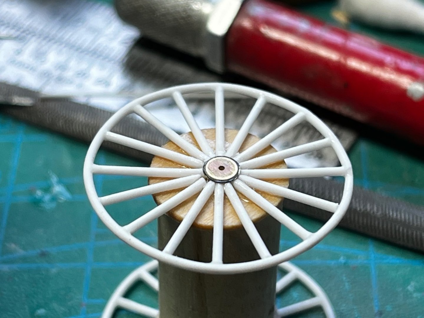
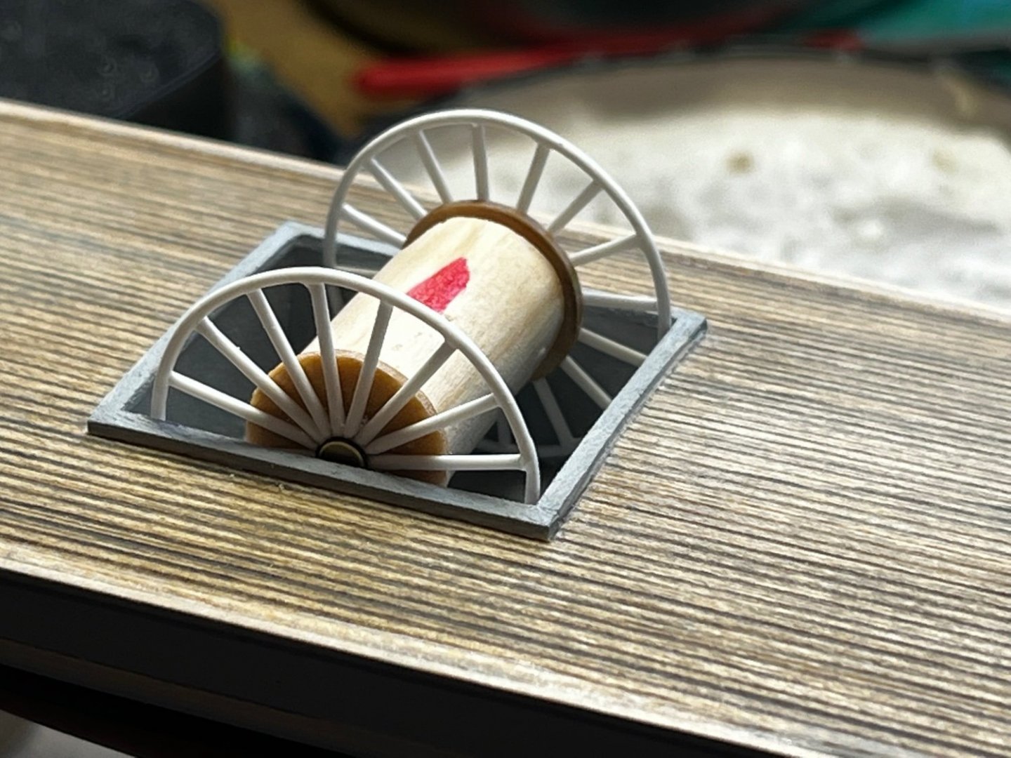
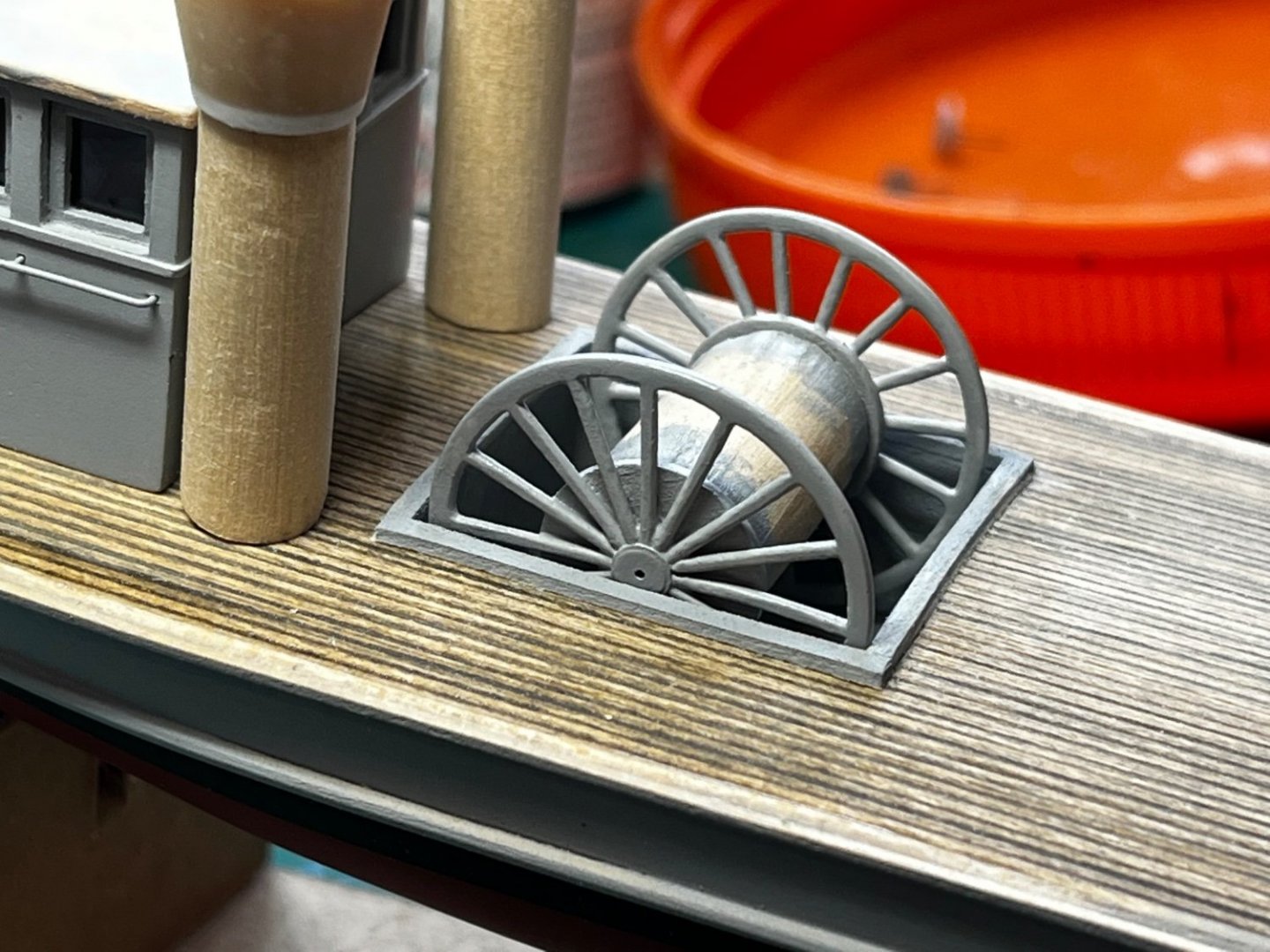
The double exhaust stacks for the gas-turbine were also a "head-scratcher." Although the boat was powered by twin diesel engines, a gas turbine was used to produce electricity for the electronic mine sweeping gear. I first tried to make the conical tops out of rolled sheet styrene, but that didn't work. So, I ended up carving them from wood dowel. The lower tubes are also wood dowel. Some styrene strip was used for trim...

These were the three big challenges I worried about the most: the pilot house, the reel, and the gas turbine exhaust stacks. The rest of the boat's details might be tedious, but I really love the detail work!
- ccoyle, Roger Pellett, yvesvidal and 10 others
-
13
-
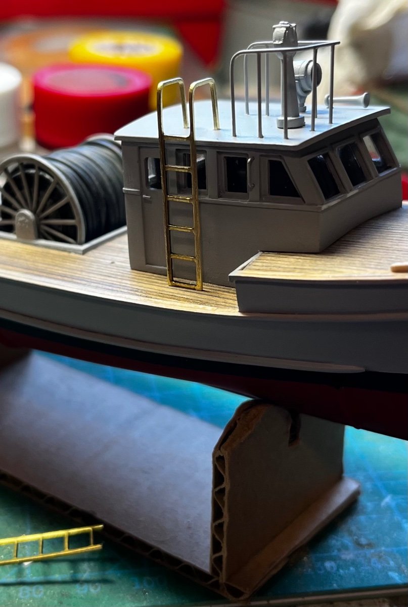
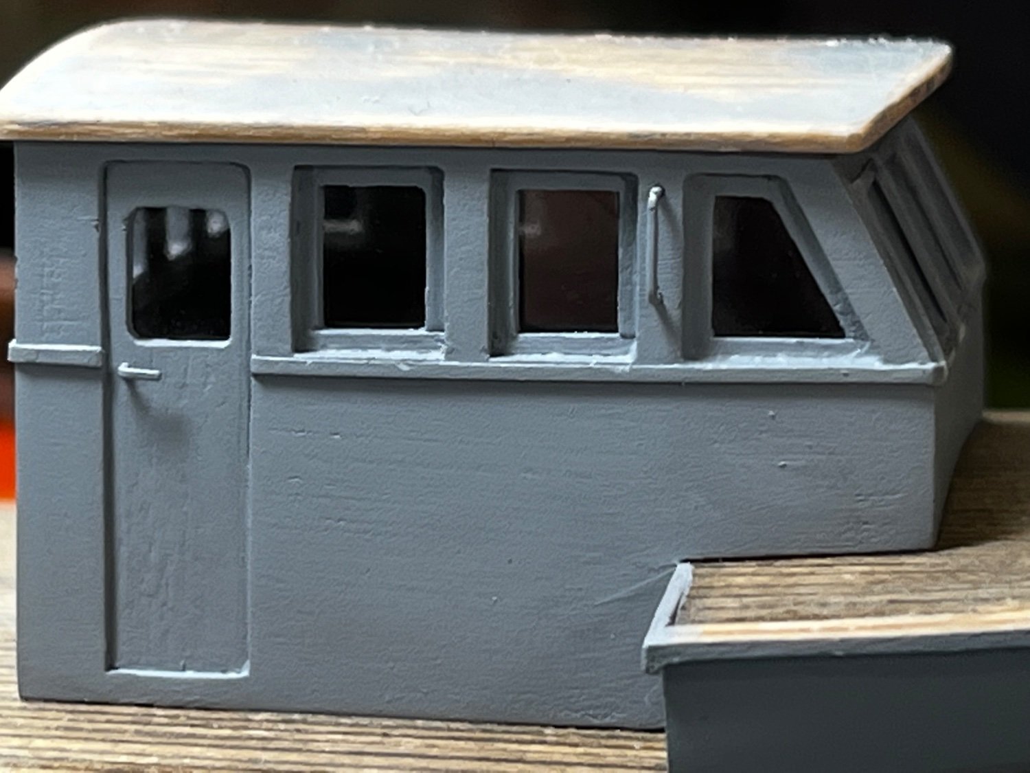
Here's the pilot house after the "glass" and roof were applied. You can also see the finished door...


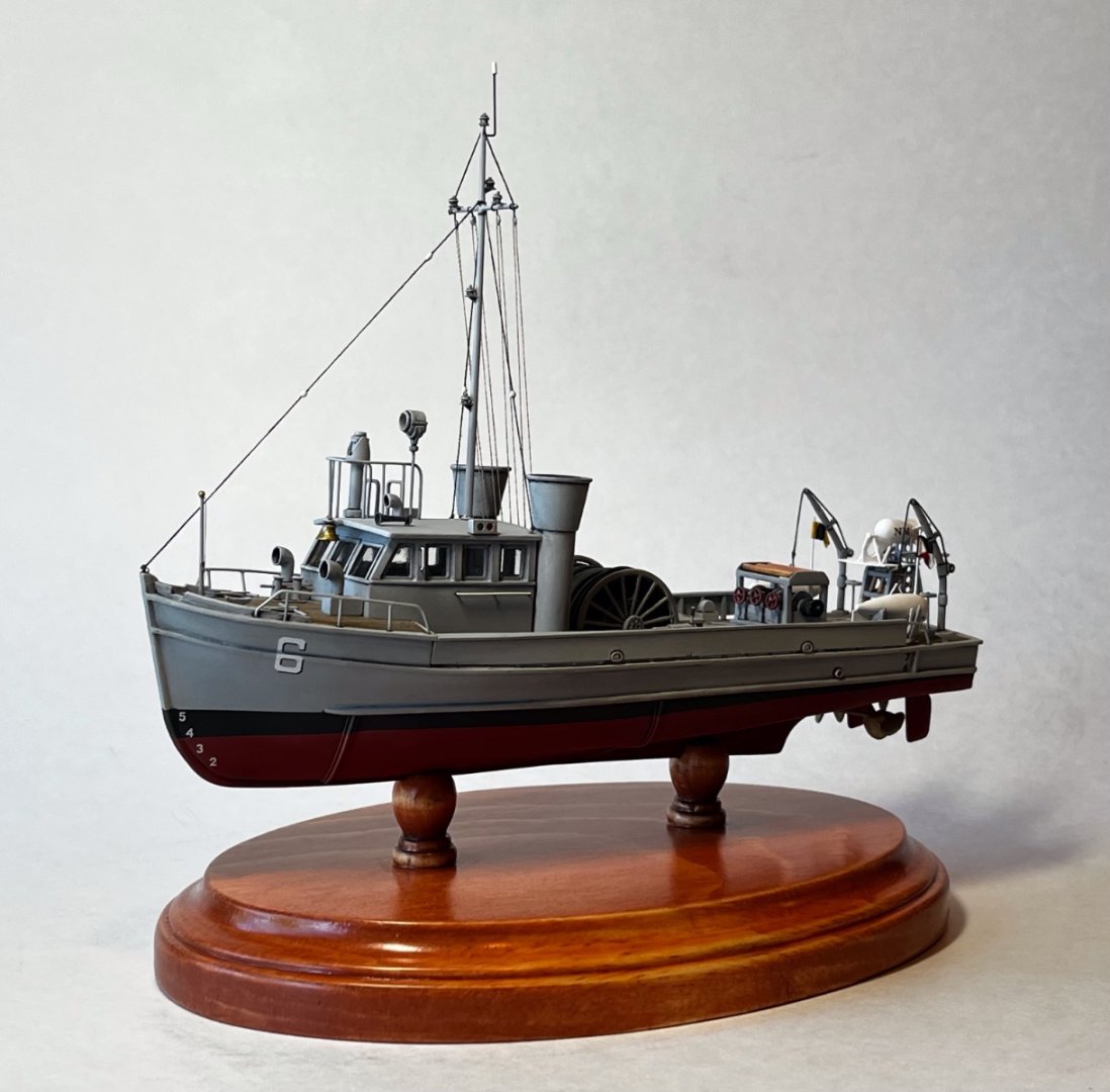
MSB 6 by Gbmodeler - FINISHED - 1/96 scale - 1952 United States Mine Sweeping Boat
in - Build logs for subjects built 1901 - Present Day
Posted
She's finished! A gallery of photos is at