


PeteB
-
Posts
183 -
Joined
-
Last visited
Content Type
Profiles
Forums
Gallery
Events
Posts posted by PeteB
-
-
On 12/4/2022 at 3:42 AM, hollowneck said:
The secret sauce on my sharpening rig is the two-sided grit "diamond stone"
Hi Ron can see one side is 1000 grit - could you let me in on the secret sauce recipe by whispering what grit you have on the reverse? Cheers Pete
- thibaultron and Canute
-
 1
1
-
 1
1
-
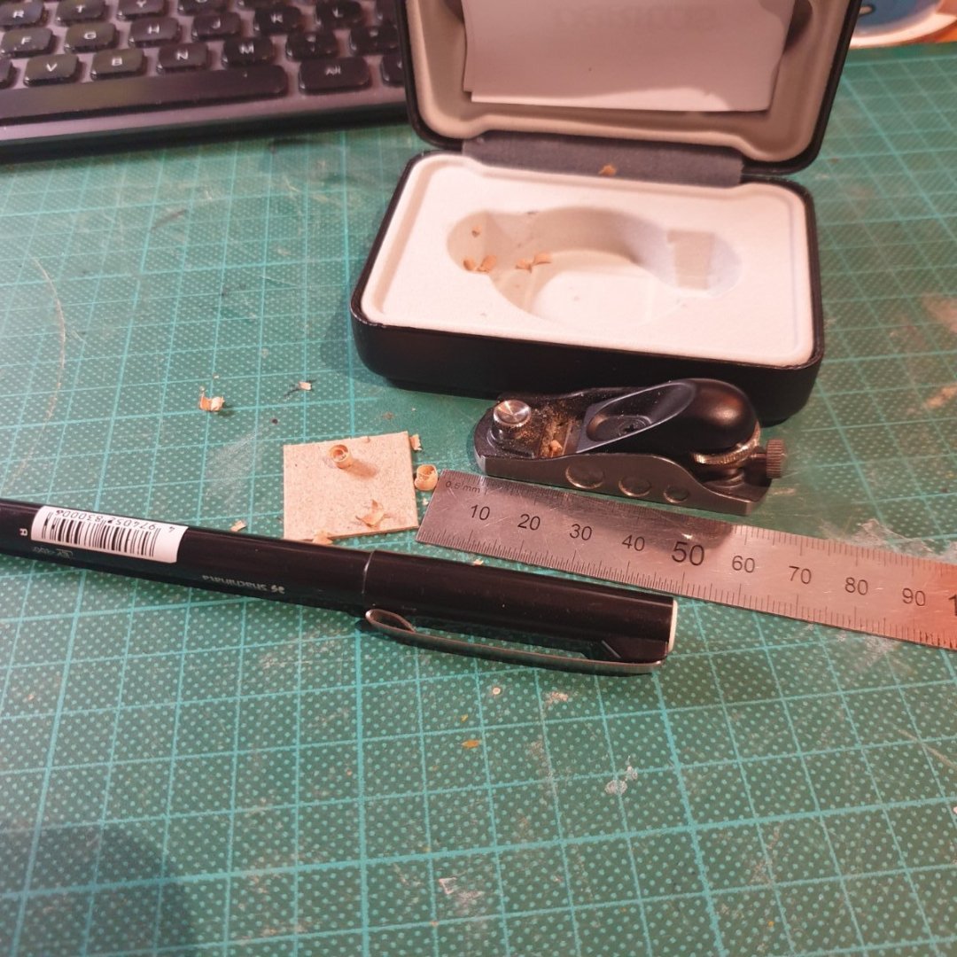
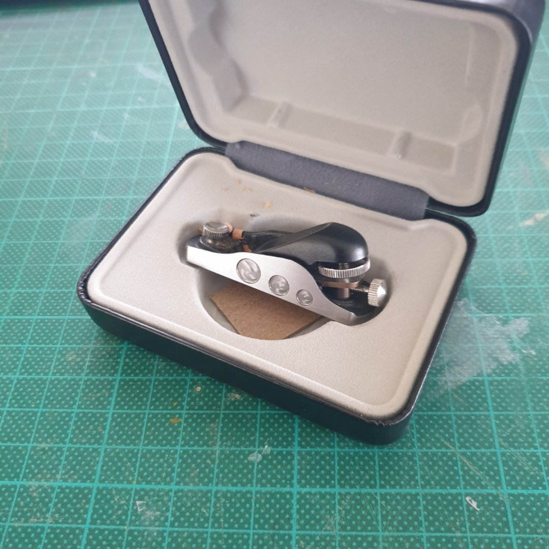
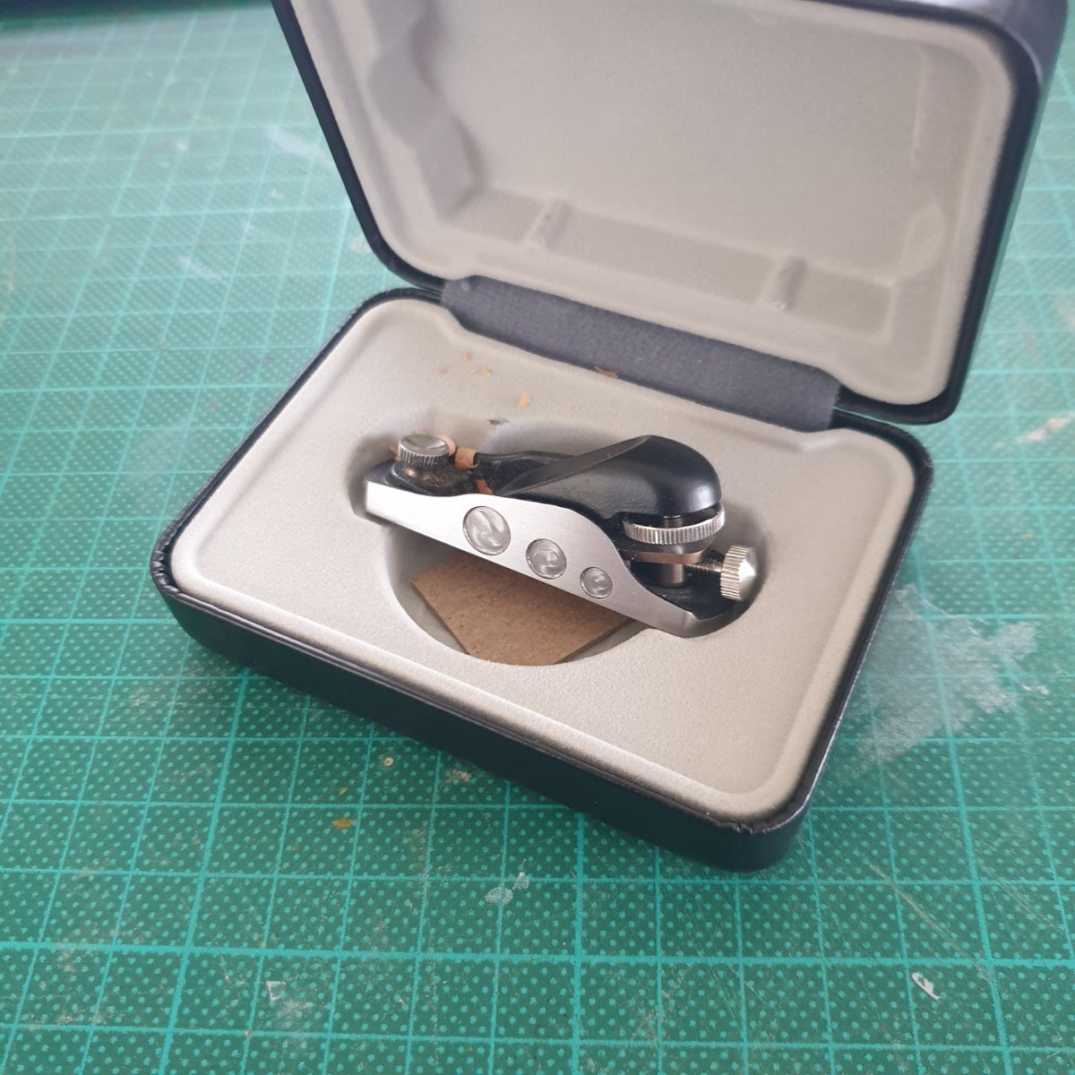
My Veritas Miniature low angle Block Plan arrived yesterday and it is a little ripper - I wasn't sure just how practicable it was going to be but a few trial strokes on some swiss pear straight out of the box convinced me, with shavings peeling away with little effort. I don't have small hands yet it was a natural fit into the mitt - so to speak - can see plenty of use for this and wasn't at all expensive costing me just $79au. Well worth the price of admission.
Cheers Pete
PS If you buy one don't throw the little cardboard square out - It is, quoting the instructions "a corrosion inhibiting chip offering continuous corrosion protection for up to two years"
-
Hi Keith - mate I bought them off evilbay just to see what they were like, at $35au they aren't .005 tolerance but for my purposes that isn't needed. As mentioned I used the Mark 2 eyeball and not a dial gauge to measure runout but to the eye and a trial step cut with the 3mm, 5mm and 7mm into Swiss Pear it looked ok to me. There were quite a few stating they were within a .005mm tolerance for not a lot more. Cheers Pete
https://www.ebay.com.au/itm/385040245651?hash=item59a62fe393:g:9WYAAOSwf2li6jHN
-
-
I’ve been looking for a solution to the Proxxon 3.2mm max shank size limitation for some time as there are very few standard profiles available in this size and I didn’t want to try and turn down shanks given the hardened metal alloys they are manufactured from.
I recently came across a replacement Spindle kit manufactured by a German Firm Usovo which will accept ER 11 collets – 1mm to 7mm - have purchased and installed the new Spindle and very happy so far.
The install is very straightforward but I had one gotcha involving the removal of the original Proxxon drive collar. The collar is retained by a 3mm Phillips Head which rounded first try and had to be drilled out.
This isn’t really a problem as the intention is for the original spindle to be discarded but I used an 2mm easy out to remove the remaining part of the screw after I removed the original spindle so as to retain it as a spare.
When fitting the new spindle, I used a new 3mm Hex socket head machine screw to replace the OEM Phillips Head - just a heads up as it isn’t part of the kit. The offending screw is shown in the instruction sheet photo step 5.
Photo 1 - Instruction sheet – see step 5 and 10 for a better view of the retaining screw and drive grommet.
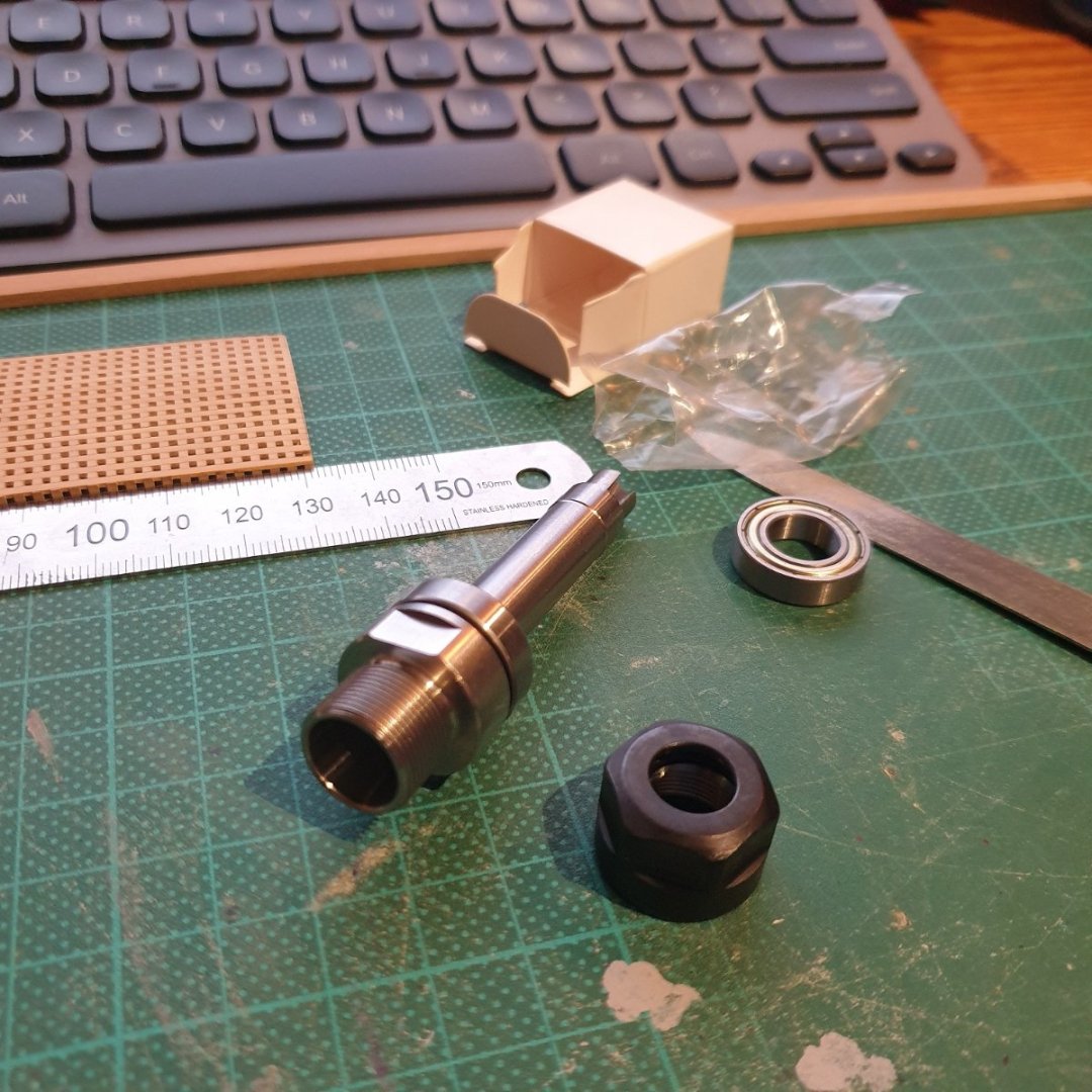
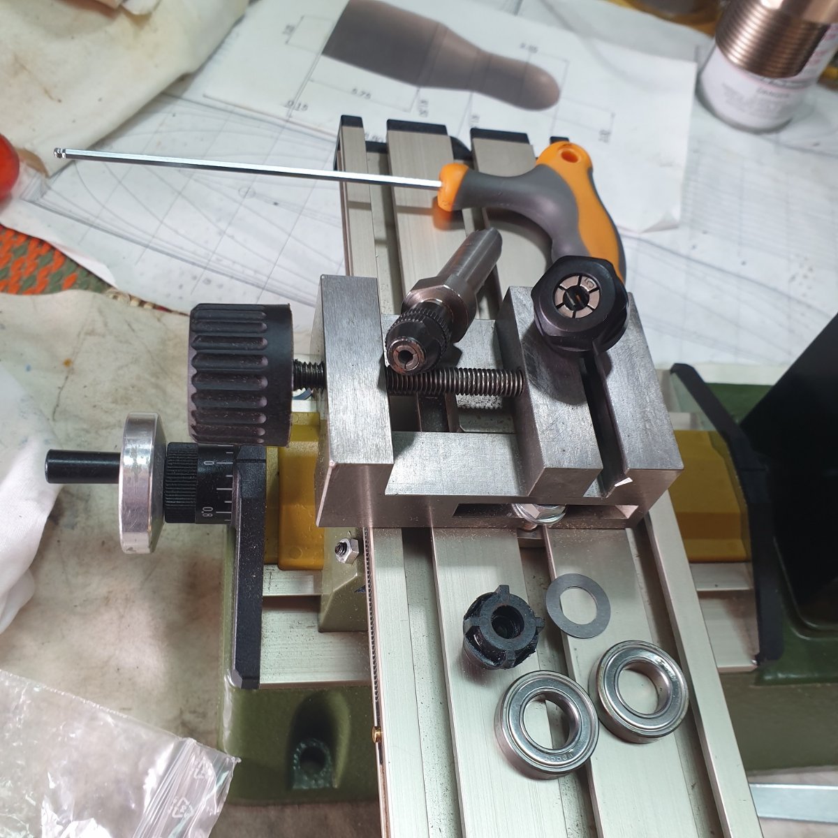
Photo 2 - shows the original Proxxon Spindle, bearings and the Drive collar. I was pretty disappointed to note the pitting and rough machining of the original spindle in what is a new and not inexpensive machine, especially when compared with the kit spindle machining shown in photo 3.
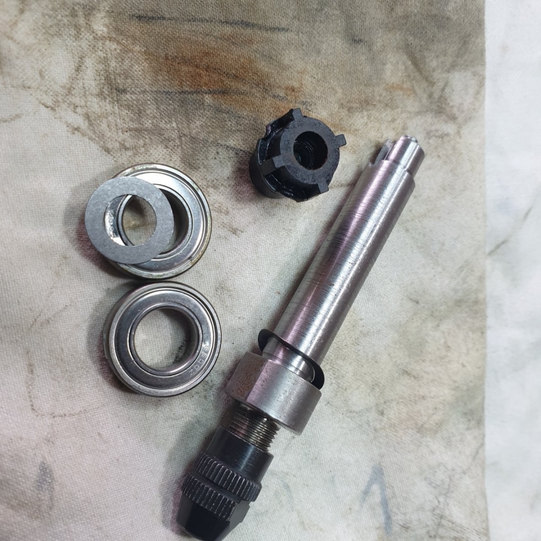
Photo 3 - Kit contents – note the lower ball race is already pressed in place on the new spindle. Also note the instructions don’t mention the obvious ie that the old bearings have to be removed.
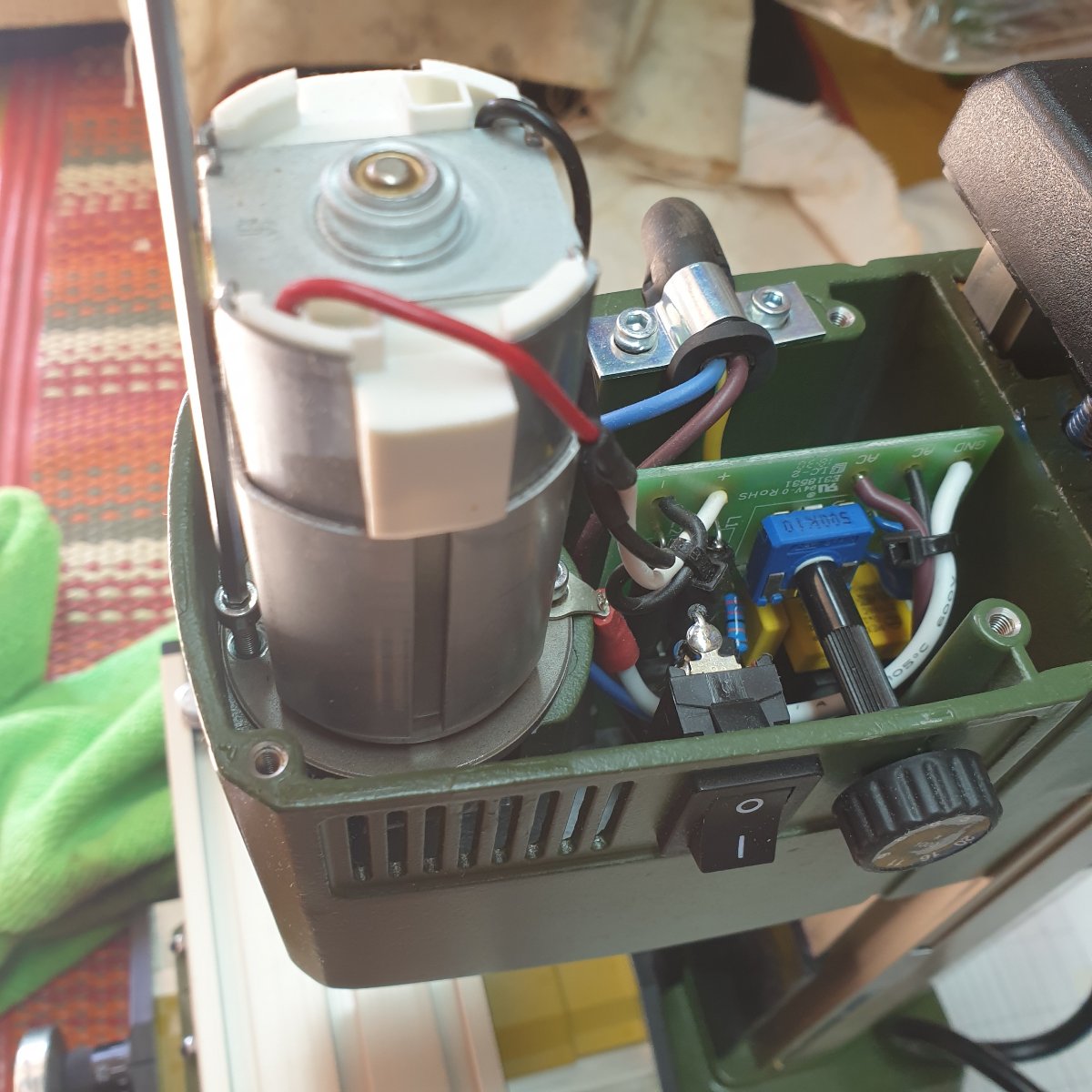
Photo 4 - shows the Hex Head Machine screws used to retain the motor so why didn’t they use one for the drive collar retainer instead of a Phillips head??
Photo 5 – Comparison of Collet holders and old bits removed. The black plastic drive collar is shown but there is a more flexible grommet not shown which press fits over the top of the drive collar
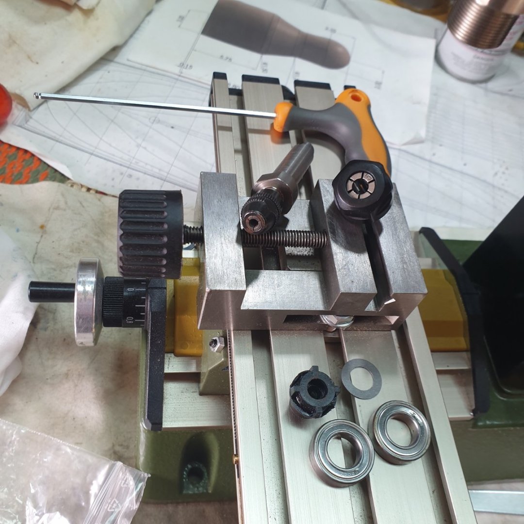
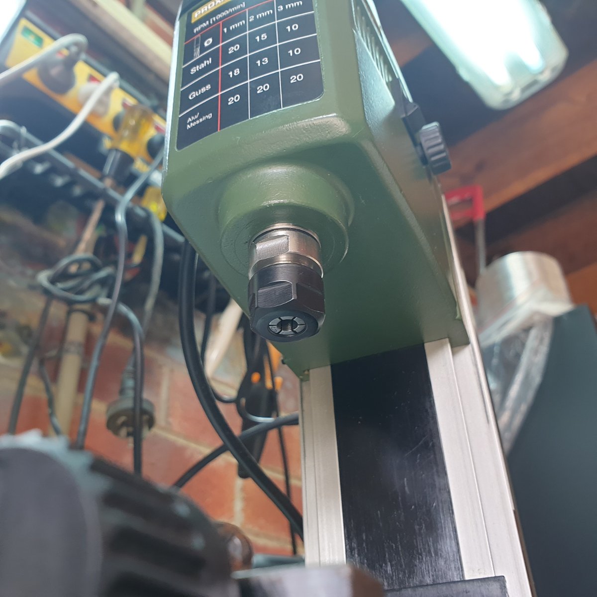
Photo 6 - New spindle installed with collet holder and a 5mm collet. The first run was noticeably quieter with no discernible runout. Very happy so far.
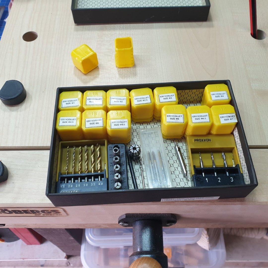
Photo 7 – Range of ER 11 collets 1mm – 7mm. Bought these on line for just under $40 and despite the homey labels they were nicely machined and supplied in individual oil filled plastic bags. Comparison of the 3mm Proxxon to the 3mm ER11 collet.
When using the larger mill bits, one has to have regard to the limited torque available and take shallower cuts but to me this is a easy limitation to accept for the far greater Type and range of standard milling bits available to the ER11 collets than the 3.2mm Proxxon max.
The link to the spindle kit is https://www.usovo.de/en/c/cnc-technology/proxxon-mf70-accessories they were great to deal with and while not cheap at 99 euro for me it offered value for money. There are two versions available for mill serial numbers above or below serial 22852.They also offer a beautiful planetary reduction gearbox for the earlier serials to give more torque for the larger mill bits – would love one for mine, a later serial, but not in the works at the moment unfortunately.
I have no financial nor any interest in the firm just posted as a heads up for many of us that have the machine. Hope this is of use to others. Cheers Pete.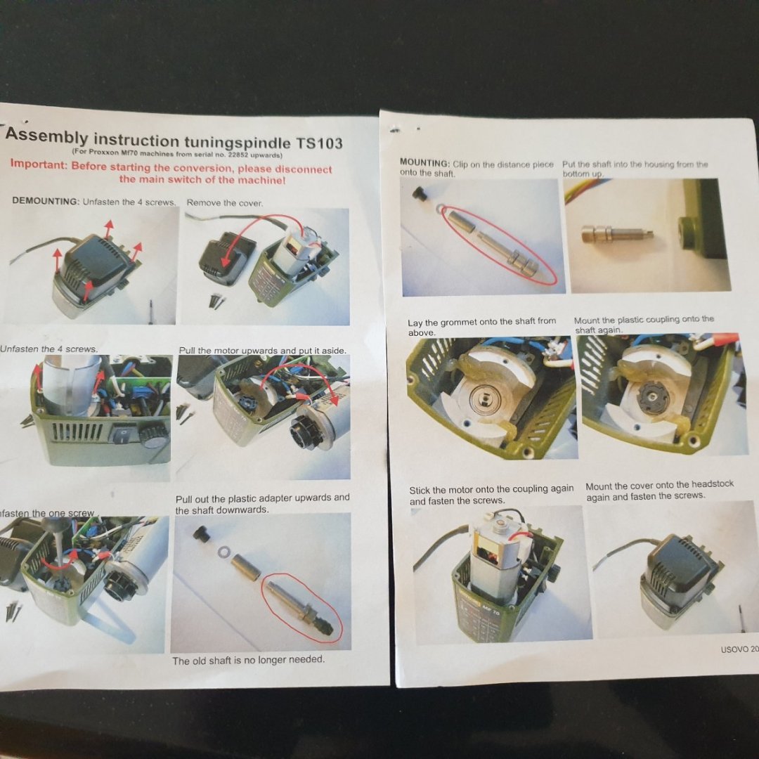


- Boccherini, John Cheevers, wefalck and 6 others
-
8
-
 1
1
-
that's the one 👍 happy building Cheers Pete
-
Ed at the risk of stating the obvious maybe I should have added that the ply parts 46, 48 and 49 will need to be steamed to match the deck camber before you try and pin them in place for a trial set up.
Once this is done and your happy with the fit - you can sand and/or pack Part 47 as required to match the camber and space between your pined parts 46 and 48.
Cheers Pete
ps - like your Sherman M4A3E8 nicely done. (in another life served in Centurions RAAC 69-71 SVN)
-
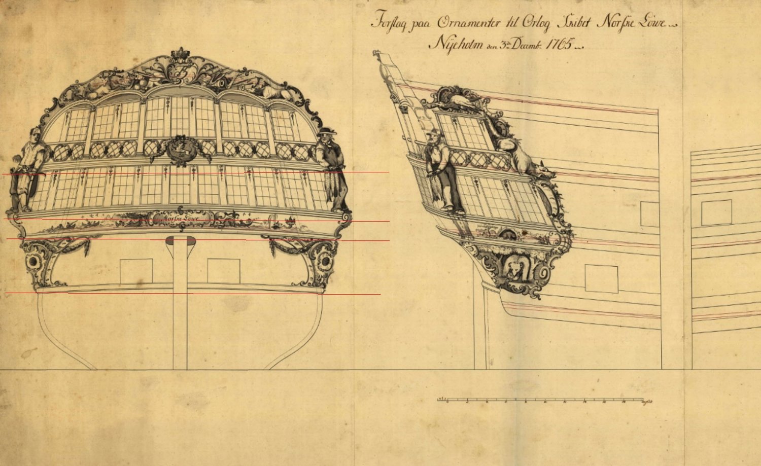
Hi Ed - don't bash yourself up you're doing pretty well getting to where you are with things looking pretty shipshape. I think the low number of completed models of the Norske on the www shows that a lot of guys have put it back into the cupboard and gone on with something simpler but you’re still in the game.
Perhaps I could offer a heads up on a couple of parts that tripped me up - right around where you are now?
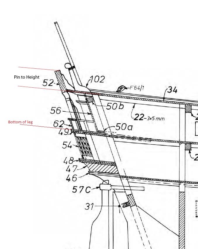
At first glance part 47 (the lower stern gallery filler piece) appears to be flat if you just look at the sectioned sheer plan or at least it did to me, but in fact when looking from astern the gallery floors curve down from amidships to each outer corner which in turn sets the height of the gallery wings. I didn't notice first time round and had to strip it out and make another.
Suggest maybe you use the large Gallery board ? - part 52 - and pin that in place first by referencing the height above the upper deck on the sheer plan. Once you’ve got that in place the legs should then give you the level of the upper gallery deck to pin in place amidships having regard to the deck camber and then the sheer plan showing both the upper deck wings and lower gallery windows sloping down to the waist in line with the Wales.
Get the above sorted and you’re home and hosed. Enjoy the rest of your build.

Cheers Pete
-
Hi Giampie -Fabulous work as always - Looking forward to your next post and seeing my first ever 1/36 skeleton - let me see... an average femure diameter say 2.4cm at 1/36 about 6.6mm "No Pressure" 🙂 Cheers Pete
- Ian_Grant, popash42 and garyshipwright
-
3
-
-
6 hours ago, Richard Dunn said:
Hi All,
Here is the link to the Webinar I held on the 23rd December. This is for all of you who are after a copy and attended or anyone who was not able to attend.
https://www.dropbox.com/s/nq8liinoh9e4gqf/Hull Form Basics in Rhino.mp4?dl=0
Regards
Richard
Hi Richard -Thanks for all your time putting the workshop together and the Time spent editing - Happy New Year to you and Yours. Cheers Pete
-
Hi Giampiero - Mate you are a “Machine”. First the beautiful “L'Amarante” at 1:30 then you follow it up with the superb “La Venus at 1:96 and to just to make it a bit more interesting you launch her in 12 months no less.
And without taking a breath here we are already on page 3 of your HMS Pegasus build log, 7588 nails later (you haven't got any of Santas Elves working off-season in your workshop have you? ). Mate that’s what gets you the title of a “Machine” down my way 🙂 – all absolutely beautiful work that I admire each time I read a post. -
No pressure but we are expecting perfection this time 😉 Stay safe Cheers Pete
- billocrates, mtaylor, giampieroricci and 1 other
-
3
-
1
-
Hi Richard Thanks from me as well - best 5 hrs I've spent acquiring CAD skills specific to our hobby . Gave me good insight into where I've been going wrong and the advantages Rhino offers in hull construction simplicity once you know the rules. Much appreciate you giving up some of your family time so close to Xmas. Best wishes to you and yours, Cheers Pete
-
-
-
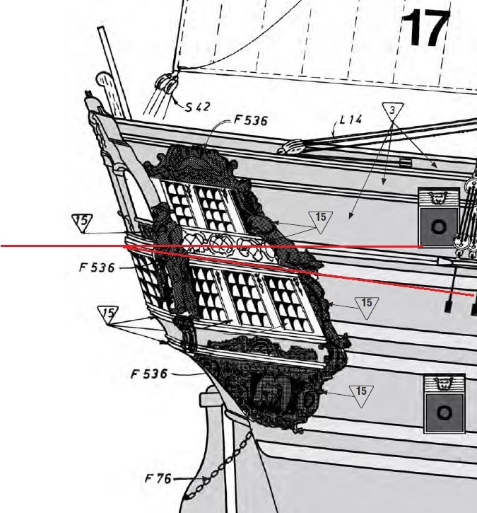
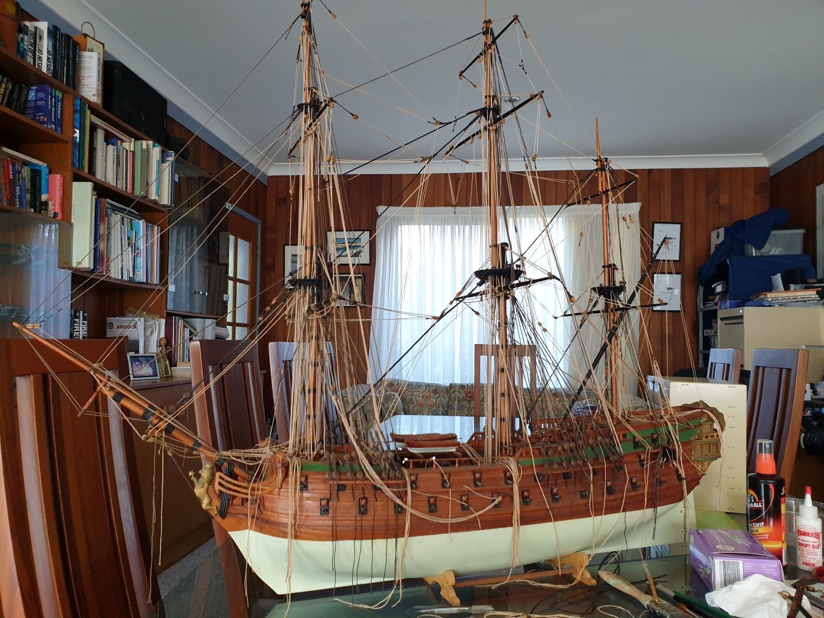
Hi Ed - been following your build with interest and see its coming along nicely. I started mine in 1983 and nearly gave it a Viking burial a few years back but decided to give it another shot and have nearly finished cleaning years of accumulated dust and gunk away.
I see you are getting close to fitting the stern gallery and walks which was an area where I really had to wrestle with the beast - so just a call out to take your time and trial fit before committing. I ended up having to put in a curved filler piece to get the spacing right for the lower quarter decoration pieces, the kit at that time was a DIY cut out so its possible I may have cut something wrong.
The other area are the Head Rails which in my kit were only supplied as flat ply and really let the rest of the model down. They are really a feature of any model and if they are the same in the current kit you might like to consider using them as templates and construct some more 3D rails out of Box or Pear. Whilst I didn't want to start a rebuild and just want to finish off the rigging - mine bug me so much I am actively considering rebuilding them.
Lastly attached a pic of mine to raise the issue of Real Estate needed, once you put up all the poles your going to need plenty. Looking forward to watching your build. Cheers
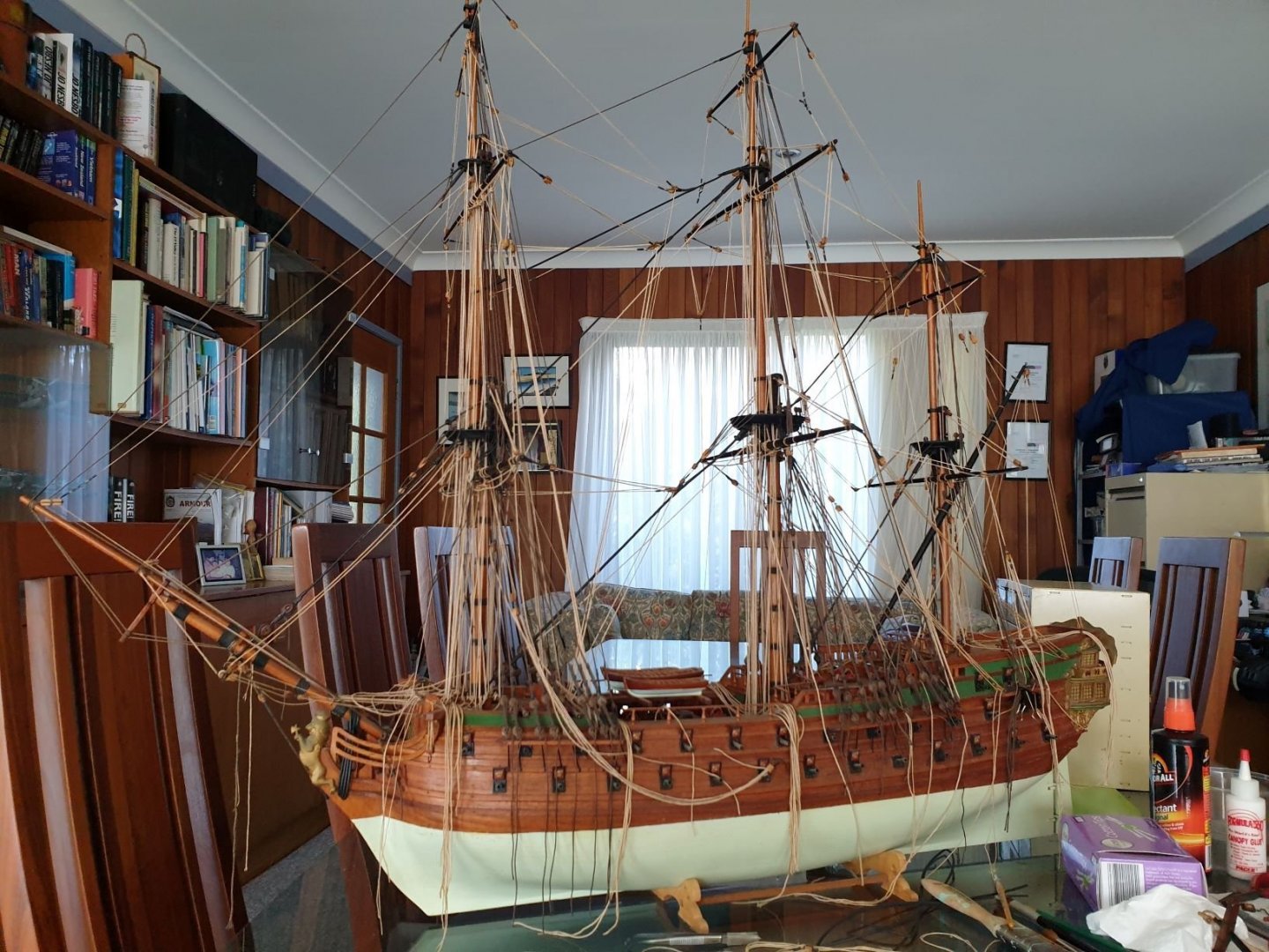 Pete
Pete
-
Hi Guys
Just went to make a donation and the donate button opened a new page being Paypal with a banner that reads
"This organisation is currently ineligible to receive donations."
any ideas ??
Cheers Pete
-
16 hours ago, No Idea said:
The only tool that I have found that I use lower is my thickness sander. I place this on a metal cupboard that is 670mm high as I like to be over the top of this tool when I'm using it
Thanks for that just what I was after, any specials I should consider. Many thanks
12 hours ago, RichardG said:We do. Recommended reading "A Shed of One's Own" by Marcus Berkmann.
Thanks for your comments Richard - put the book on my Library Order in list, though reading a review leads me to think I should have read it 20 years ago to ease into old age where I now find myself. Cheers
7 hours ago, grsjax said:I am one of the height challenged at 5'7". I find a bench height of 30" works well for sitting and one 36" for standing.
I now regret mentioning the height challenged - my apologies grsjax . Thanks for your input its much appreciated. Cheers.
5 hours ago, RichardG said:One of the problems I find is how the heights of tools vary. For example I have a scroll saw with a table and a spindle sander also with table - about 8" higher than the saw.
The various tool heights had been in my mind before posting.
5 hours ago, RichardG said:And while we're talking about annoyances, I have 5 power tools with 4 different sizes of dust port
I hear what you are saying I was mulling having to join various pvc tube myself until I discovered these adapters at our local hardware

I've set up a temp bench this morning and find around 950mm or 38"in the old money looks like it would be ok for general joinery and hull work using the lathe mill and disc sander but as @no idea pointed out the thickness sander and table saw might benefit from being a bit lower. So I think Ill set up the first bench at 950mm and trial some lower benches heights before the final fix the two others on the stud wall side.
Thank you all for responding - nice to have the benefit of your experience. Stay safe and happy modelling.
Cheers Pete
-
Hi Guys - I have taken possession of 4.2 x 3.5metres of our tandem garage by "force majeur" for a man cave the end of which I will close off with a Stud wall.
I have potentially 10 metres + of bench space after subtracting for a door, a free standing Band saw and a desk and would appreciate some advice as to how to calculate a good bench height to mix and match the rest of my bench tools if your experience suggests differing heights are desirable for the different activities.
Seeking to place - Byrnes table saw & thickness sander, Proxxon - 230 lathe, MF 70 Mill and scroll saw - Bench disc and belt sander Ryobi Bench Drill Press and 150mm bench grinder. Your thoughts would be much appreciated.
Should say I'm not height challenged at 6ft 1 and a range for various activities would be fine.
Cheers Pete
-
-
Hi Johnny Mike - I'm a bit late to the party but I've been after a table that size for a while and haven't seen on like that before. IKEA have a larger model which looks ok but the want your first born for it. Could you tell me where you purchased it ? Cheers Pete
- thibaultron, Canute and Jasseji
-
3
-
-
Hi Marsalv - Just been catching up and was about to say that every time I look in the work keeps getting better and better but realized that isn't the case your work has been at this extraordinary level of precision right from the start.
I don't often have cause to say this, but for me I genuinely find your build inspiring and/or aspiring (not sure of my english here) even though I have no illusions of being able to replicate the same result - thank you. One question if I may ? in your earlier post you show your plank caulking method - is it thin card stock you are using or are they very thin hornbeam strips ?
I'll keep you from your work no longer - Stay safe - Cheers Pete
On 3/27/2020 at 7:44 PM, marsalv said:Some deck details - inner waterways, binding strake, carlings and ledges.
-


My laser cut planks
in Building, Framing, Planking and plating a ships hull and deck
Posted
Hi Gregory - which 20W /40W Blue diode laser would you recommend looking at having regard to our modelling needs? Cheers Pete