


mbp521
-
Posts
934 -
Joined
-
Last visited


-
 mtaylor reacted to a post in a topic:
Caroline N by mbp521 - Scale 1:64 - Mississippi River Towboat
mtaylor reacted to a post in a topic:
Caroline N by mbp521 - Scale 1:64 - Mississippi River Towboat
-
mtaylor reacted to a post in a topic:
Caroline N by mbp521 - Scale 1:64 - Mississippi River Towboat
-
mtaylor reacted to a post in a topic:
Caroline N by mbp521 - Scale 1:64 - Mississippi River Towboat
-
 mtaylor reacted to a post in a topic:
Caroline N by mbp521 - Scale 1:64 - Mississippi River Towboat
mtaylor reacted to a post in a topic:
Caroline N by mbp521 - Scale 1:64 - Mississippi River Towboat
-
mtaylor reacted to a post in a topic:
Peerless by Cathead - 1:87 - 1893 sternwheel Missouri River steamboat
-
mtaylor reacted to a post in a topic:
SMS WESPE 1876 by wefalck – 1/160 scale - Armoured Gunboat (1876) of the Imperial German Navy as first commissioned
-
GrandpaPhil reacted to a post in a topic:
Caroline N by mbp521 - Scale 1:64 - Mississippi River Towboat
-
Ras Ambrioso reacted to a post in a topic:
Peerless by Cathead - 1:87 - 1893 sternwheel Missouri River steamboat
-
Canute reacted to a post in a topic:
Peerless by Cathead - 1:87 - 1893 sternwheel Missouri River steamboat
-
 Definitely a lot of work went into the ensign, but the results are spectacular and well worth it. -Brian
 -
mbp521 reacted to a post in a topic:
SMS WESPE 1876 by wefalck – 1/160 scale - Armoured Gunboat (1876) of the Imperial German Navy as first commissioned
-
mbp521 reacted to a post in a topic:
Caroline N by mbp521 - Scale 1:64 - Mississippi River Towboat
-
mbp521 reacted to a post in a topic:
Caroline N by mbp521 - Scale 1:64 - Mississippi River Towboat
-
Hardly Eric. Each boat you build is beautiful tribute to some of the lesser known vessels of the Western rivers. I love the fact that the subject of each of your scratch builds are some of the more obscure boats rather than one that tends to be overbuilt. Add in the fact that you try your best to mill your own lumber sourced from your property whenever possible. I say nothing downhill about that. In my eyes they are all works of art. -Brian
-
mbp521 reacted to a post in a topic:
Peerless by Cathead - 1:87 - 1893 sternwheel Missouri River steamboat
-
mbp521 reacted to a post in a topic:
Peerless by Cathead - 1:87 - 1893 sternwheel Missouri River steamboat
-
mbp521 reacted to a post in a topic:
Peerless by Cathead - 1:87 - 1893 sternwheel Missouri River steamboat
-
Thank you Kurt for chiming in with that detailed explanation. Being a complete novice in this era of ships, I was only able to explain what I read about while researching the rudder design. I didn’t delve too much into the science behind it, but it all makes sense. I can only imagine the enjoyment you got showing up the pilots with the RC boats. I used to be into RC planes and it was a similar situation when actual pilots would show up to the model air fields thinking that if they could fly an actual plane, an RC one would be a piece of cake. I never had the opportunity to show a pilot up myself, but at some of the model air shows I attended I saw it happen more than once. Fortunately I never saw any of the attempts end in disaster. Most of the RC pilots only allowed them to fly with a trainer lead attached to their remotes. -Brian
-
mbp521 reacted to a post in a topic:
Caroline N by mbp521 - Scale 1:64 - Mississippi River Towboat
-
 mbp521 reacted to a post in a topic:
Caroline N by mbp521 - Scale 1:64 - Mississippi River Towboat
mbp521 reacted to a post in a topic:
Caroline N by mbp521 - Scale 1:64 - Mississippi River Towboat
-
mbp521 reacted to a post in a topic:
Caroline N by mbp521 - Scale 1:64 - Mississippi River Towboat
-
mbp521 reacted to a post in a topic:
Caroline N by mbp521 - Scale 1:64 - Mississippi River Towboat
-
Thank you Eberhard, I have the same setup and keep all of my photos on a backup drive and generally back them up monthly. When I take pictures of my builds I put them in a different folder that contains all my research and other documents. I have to scale them down, otherwise the files are too big and MSW website will not upload them. Once my build is completed I save the entire folder on the hard drive as well to free up storage space. This folder is also backed up monthly. Unfortunately, my old laptop died before I could back it up and lost some of the pictures, but I was fortunate enough that most of them were still on my phone. Keith, Eberhard, this rudder arrangement is pretty standard on this type of towboat. They are called flanking rudders and are used to add maneuverability to the boats when setting up the tows and to help with navigating the twists and turns of the narrow, shallow rivers. They help the main rudders at times by providing sideways force to help swing the tows around, which can get to more than 1000' long. I am definitely considering it. Since I am building this one for somebody else, I'll need to make sure that there will be enough room where he plans on displaying it. Going to a Mac was the best computer move I ever made. I wish I would have converted sooner. I've already filled my complementary iCloud storage and had to purchase more. Still worth it. -Brian
-
Thank you Keith. I am definitely happy with the way the underside of the hull turned out. Lots of little details going on there that I am not used to. I may have to look into installing a mirror under the hull once I’m finished. Right now my plan is to only have her sitting about an inch off the base, so I’m not sure how much would be visible in a mirror, but that plan can change. One never knows. I still think there were more photos of my progress that I had on my old laptop that I was not able to recover. Fortunately it died before I downloaded all of them off my phone so I managed to hang on to the bulk of them. - Brian
-
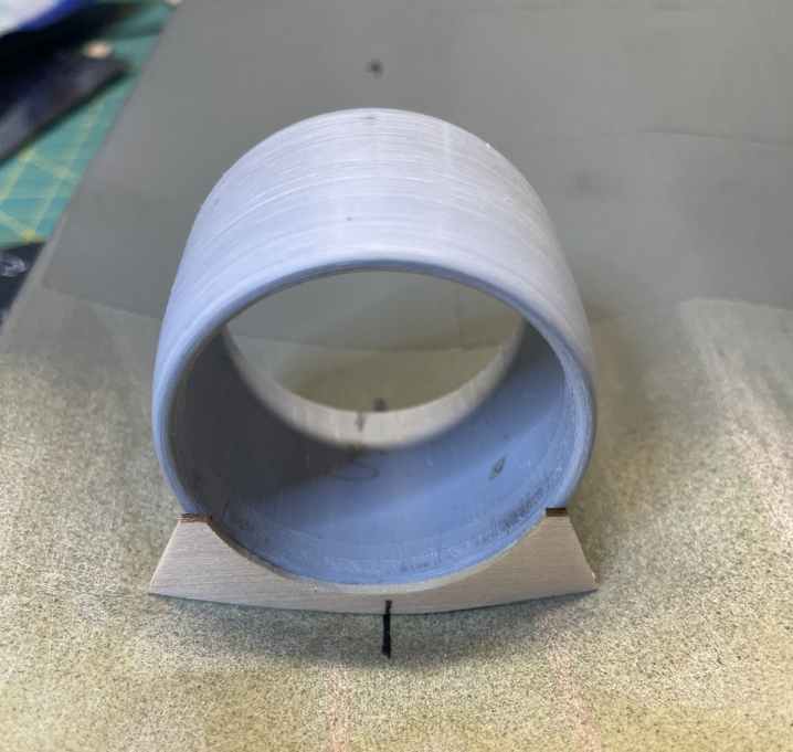
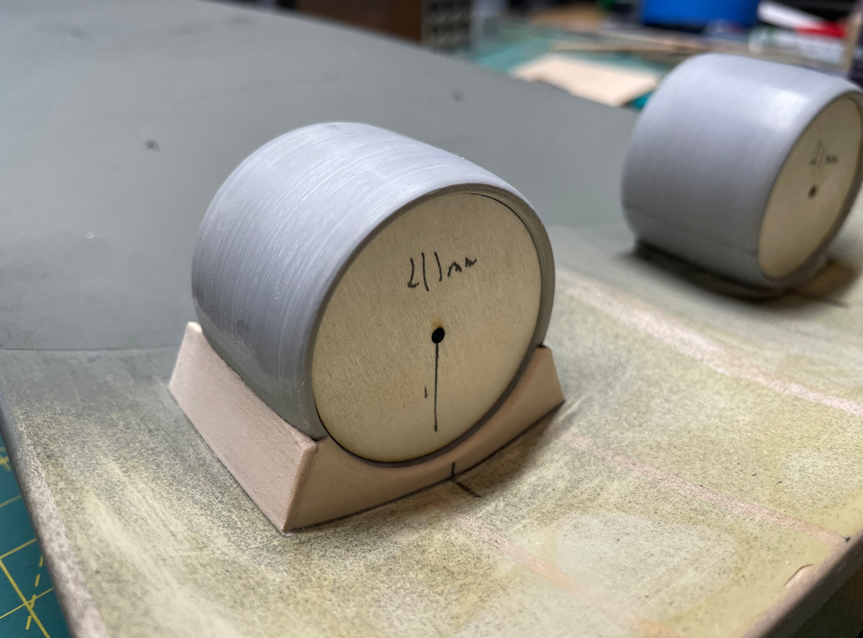
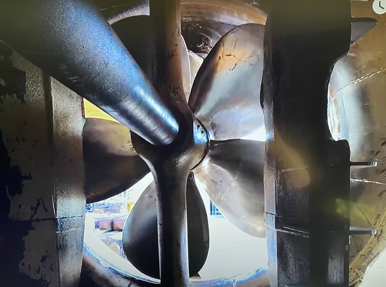
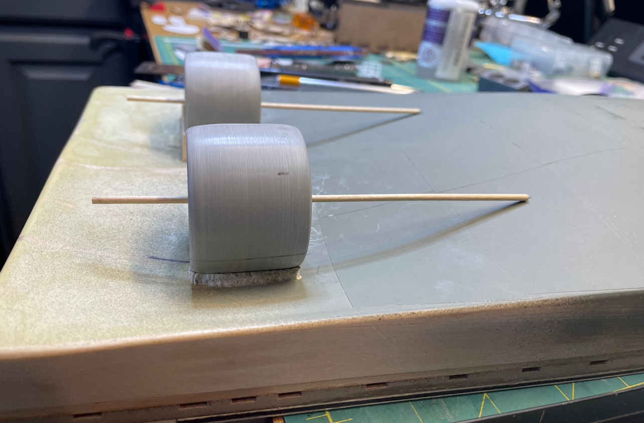
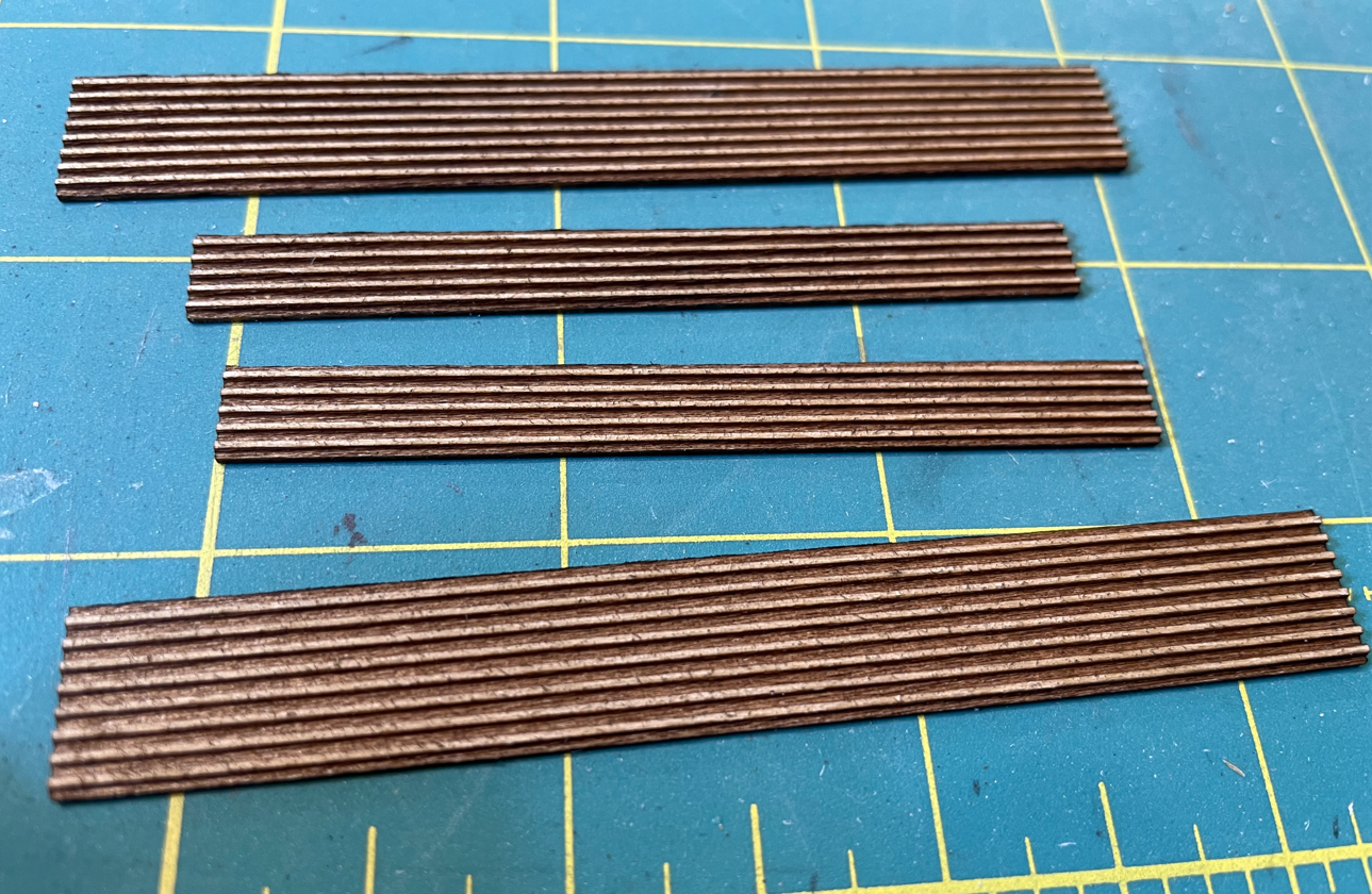
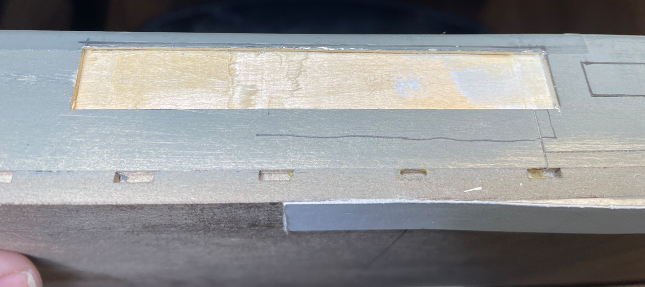
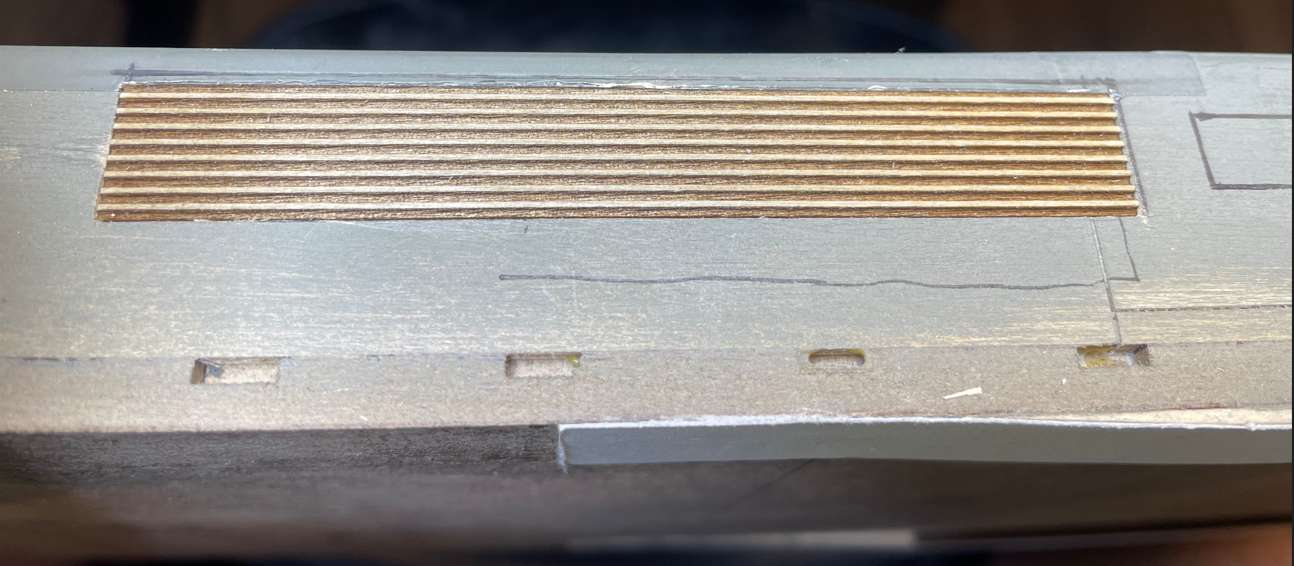
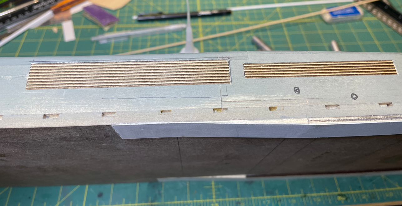
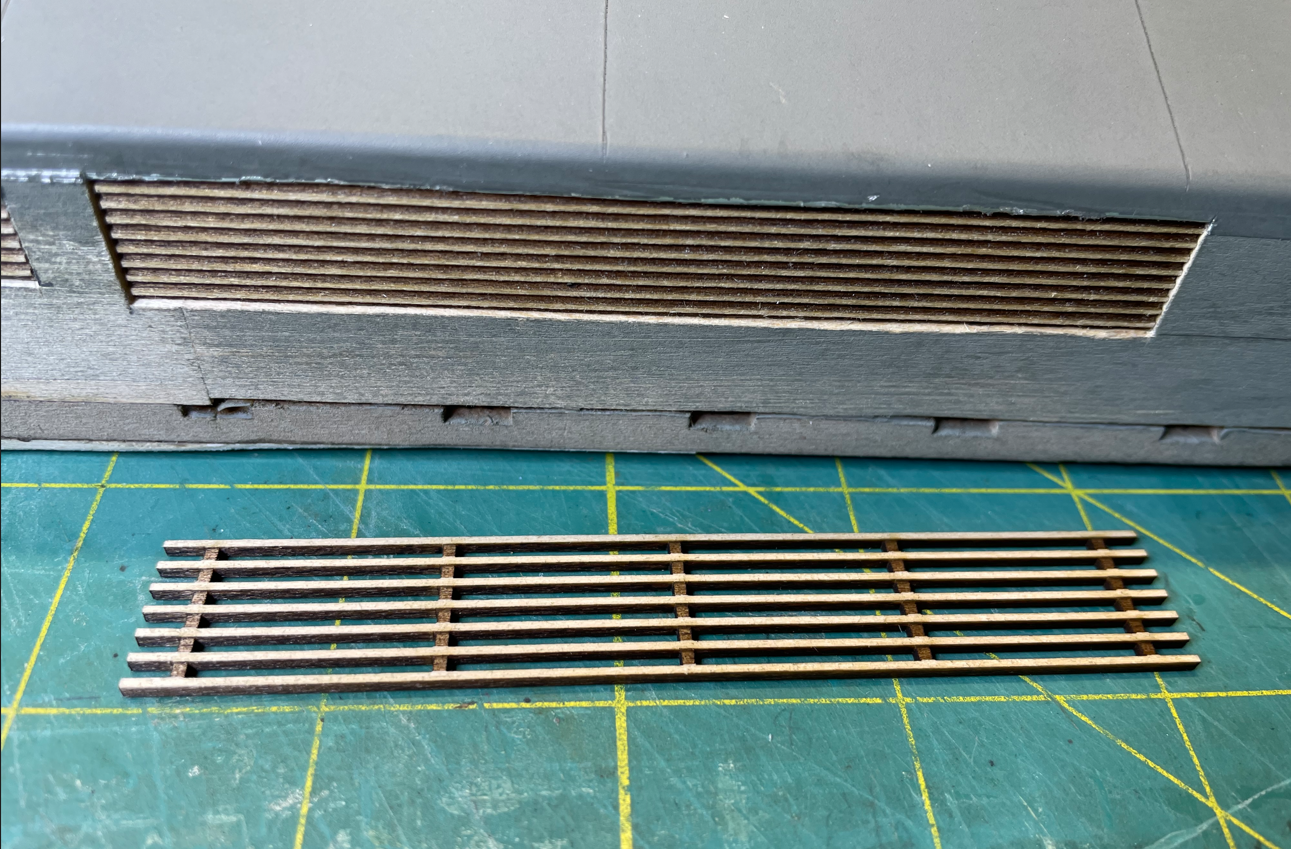
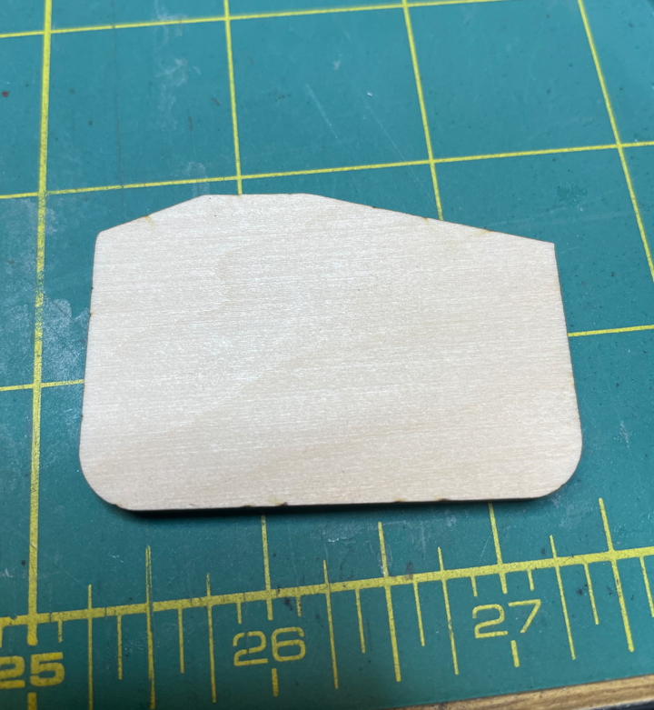
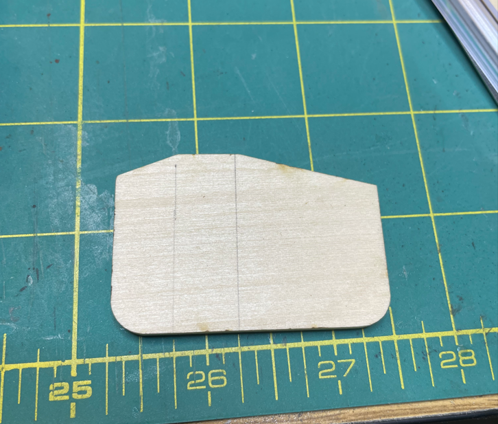
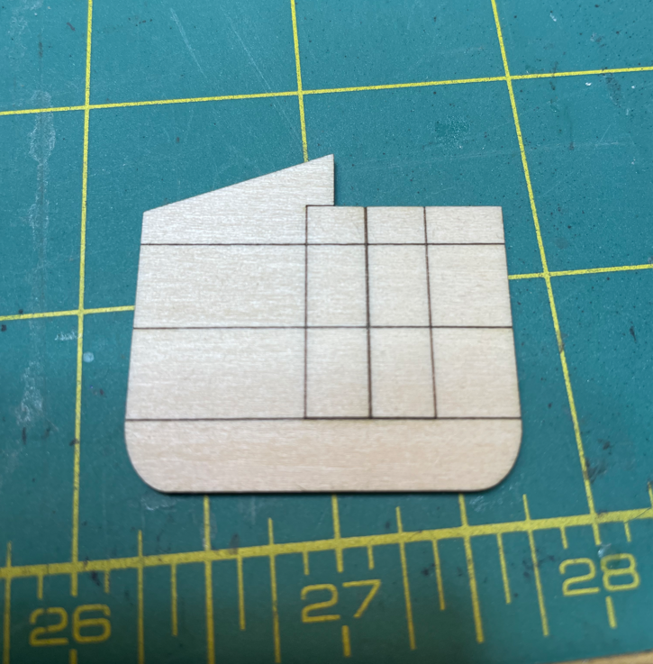
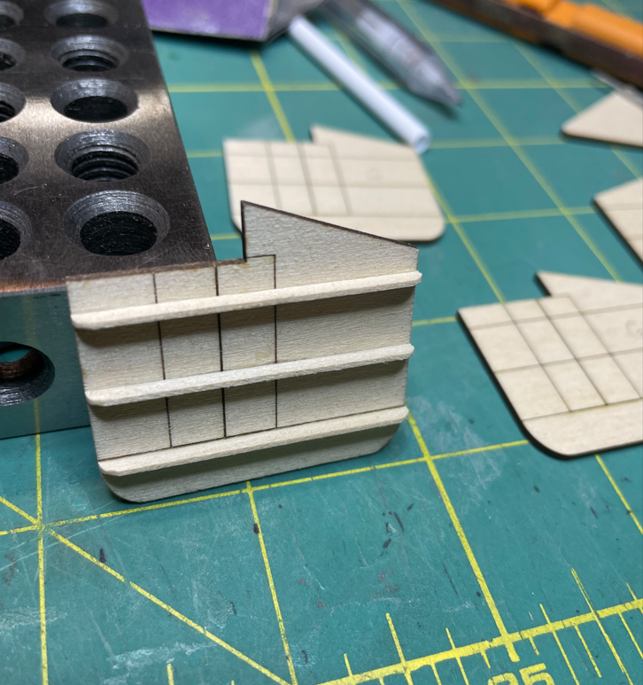
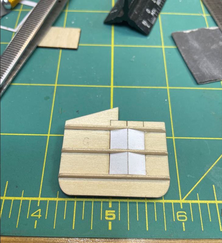
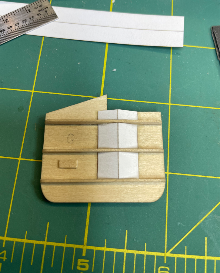
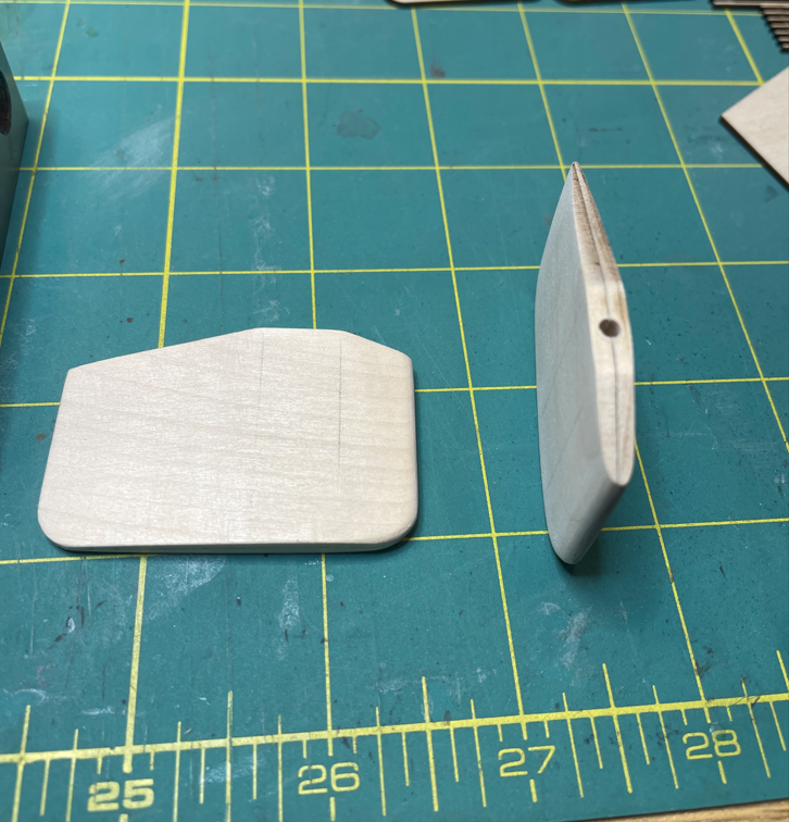
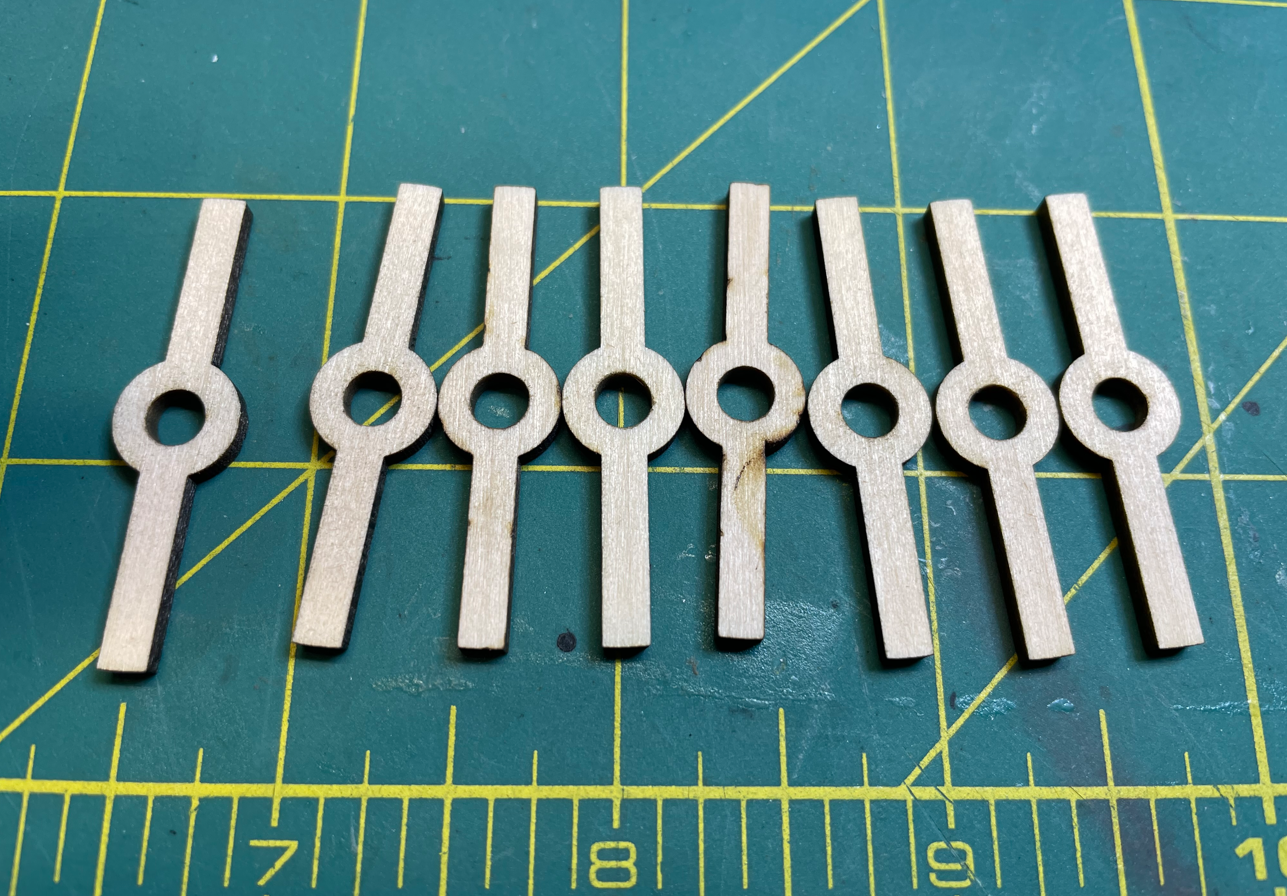
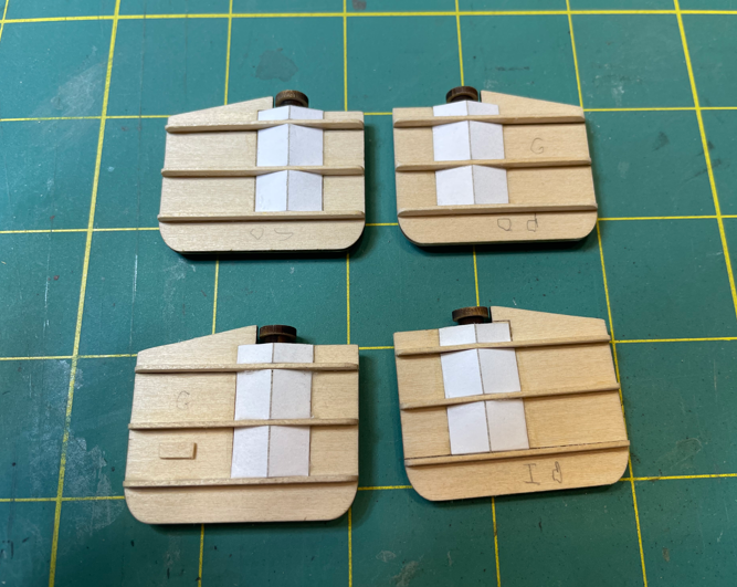
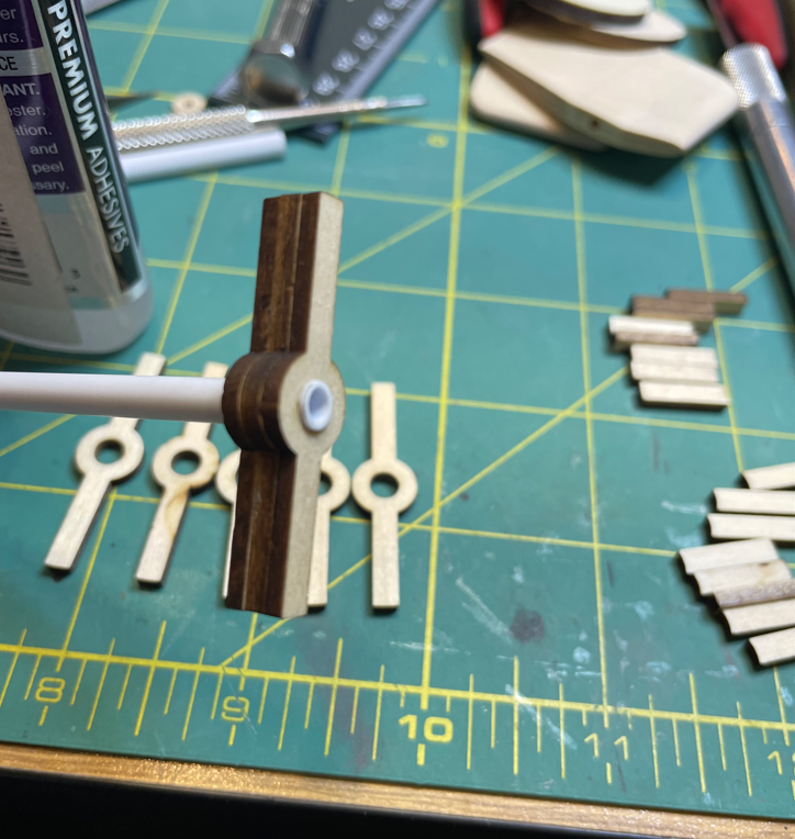
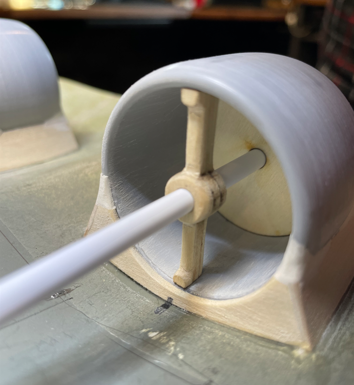
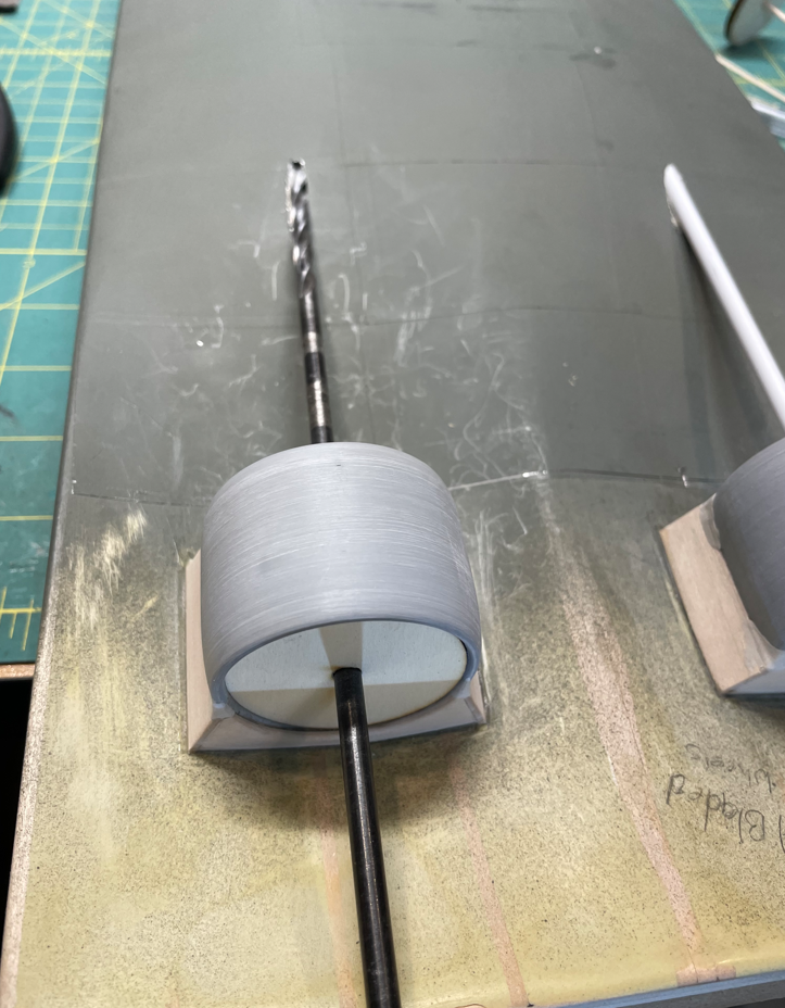
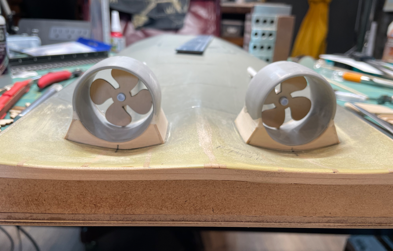
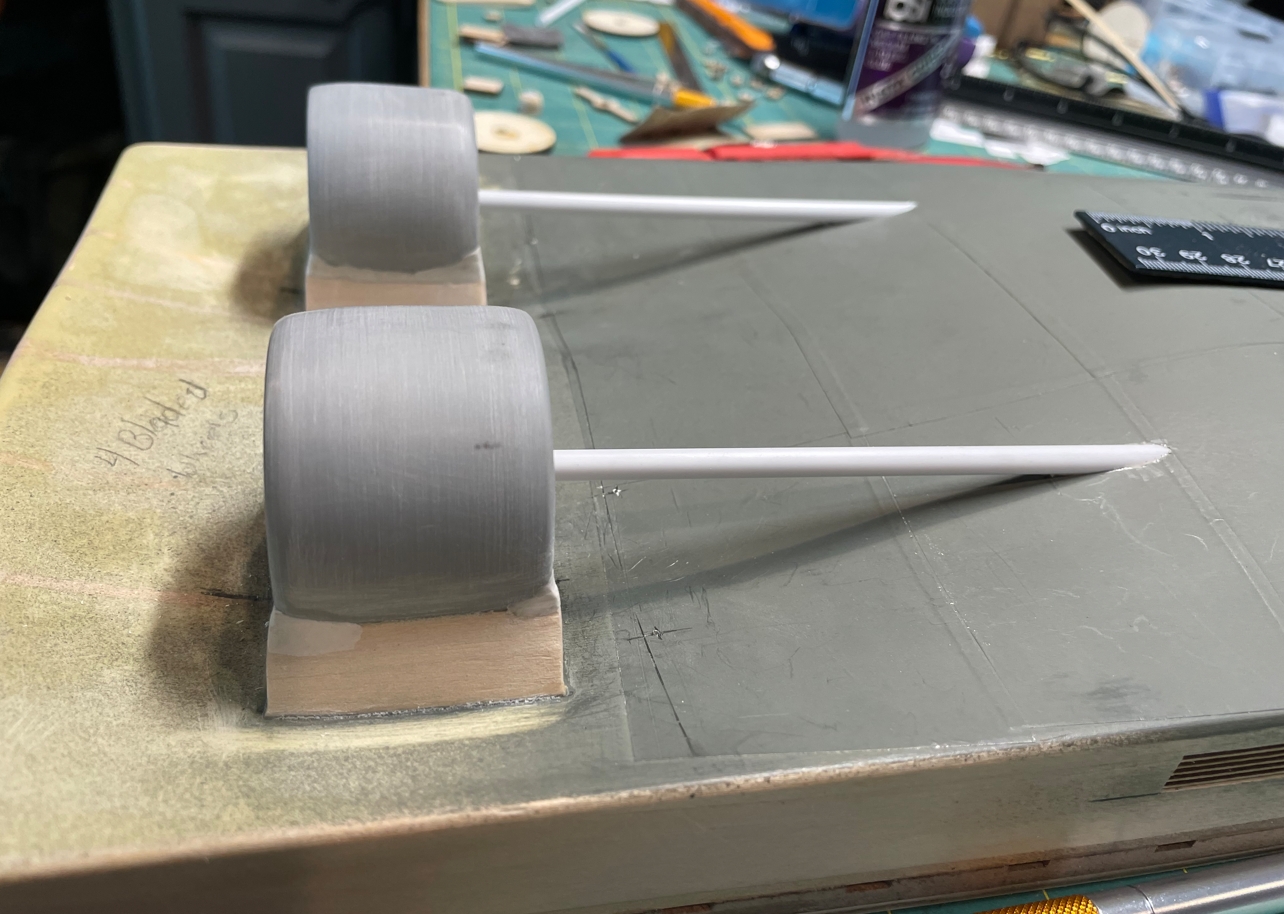
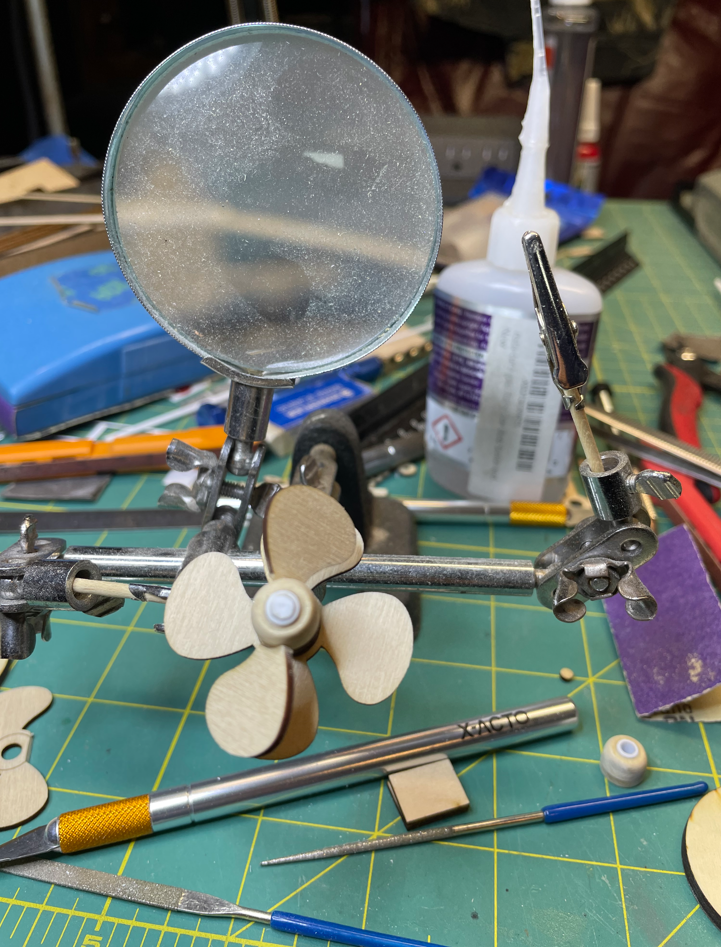
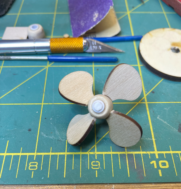
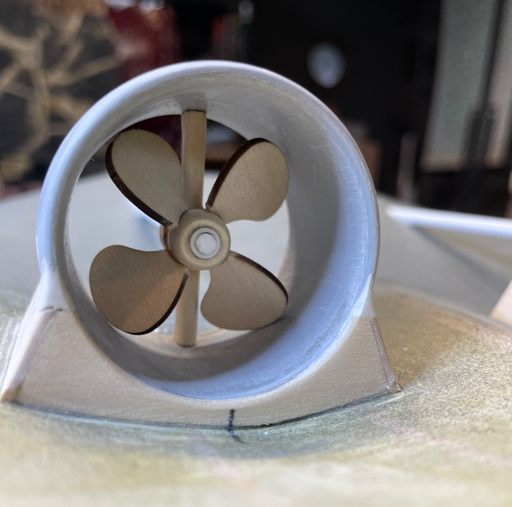
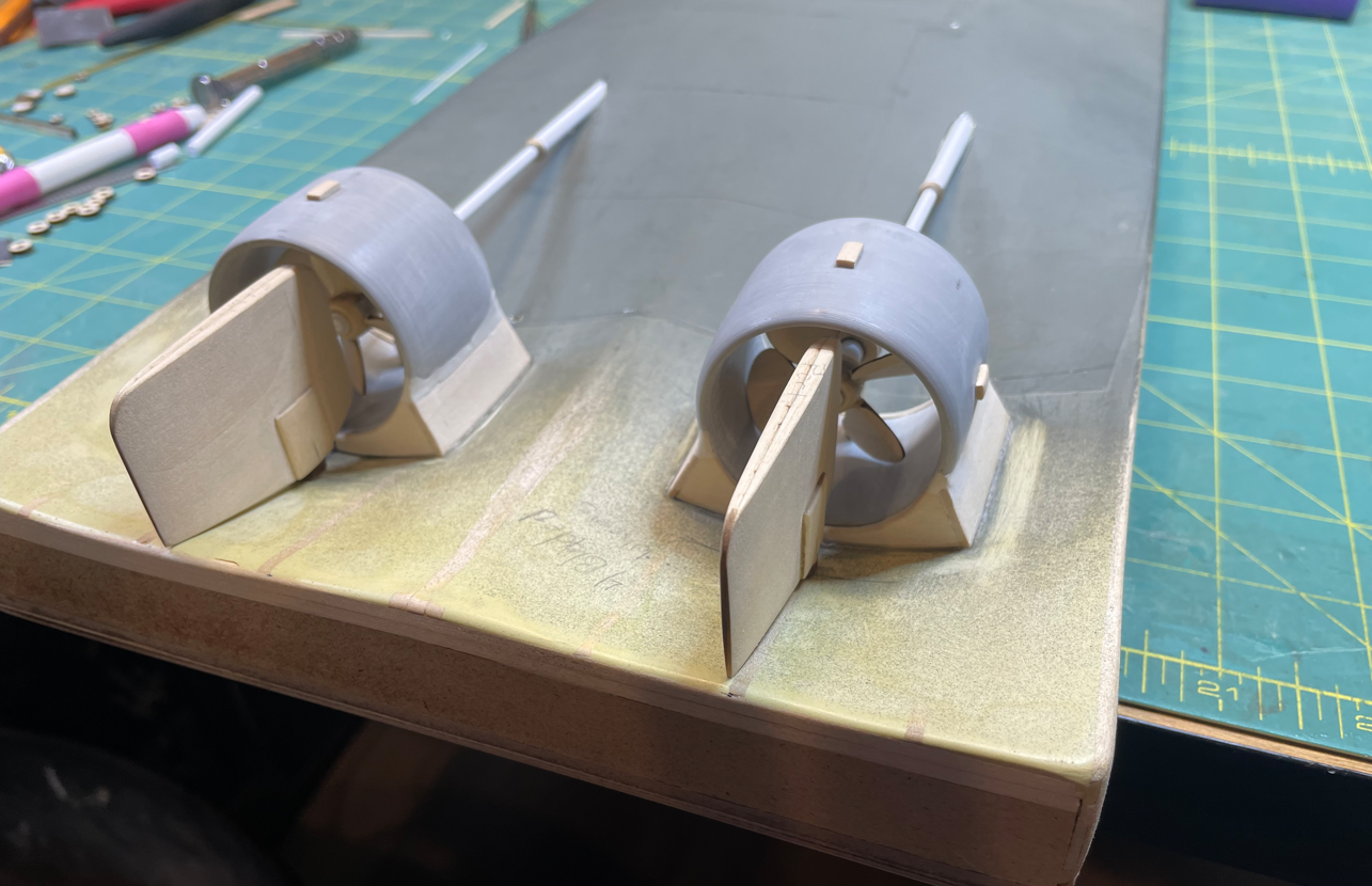
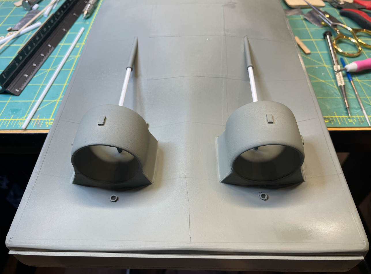
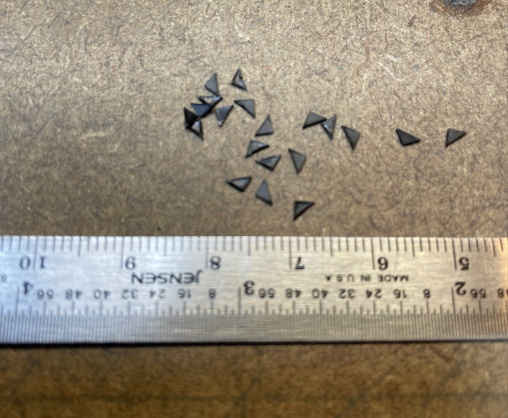
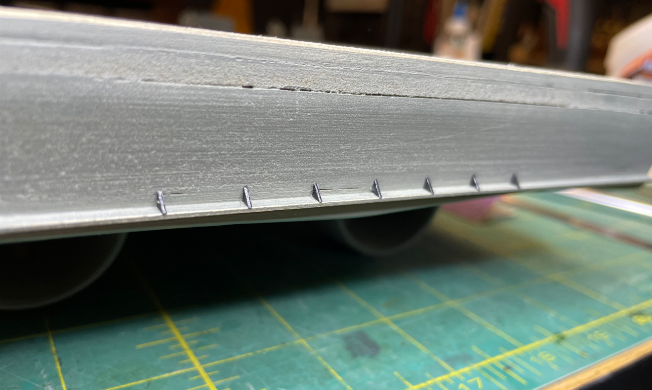
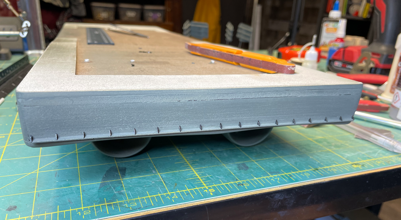
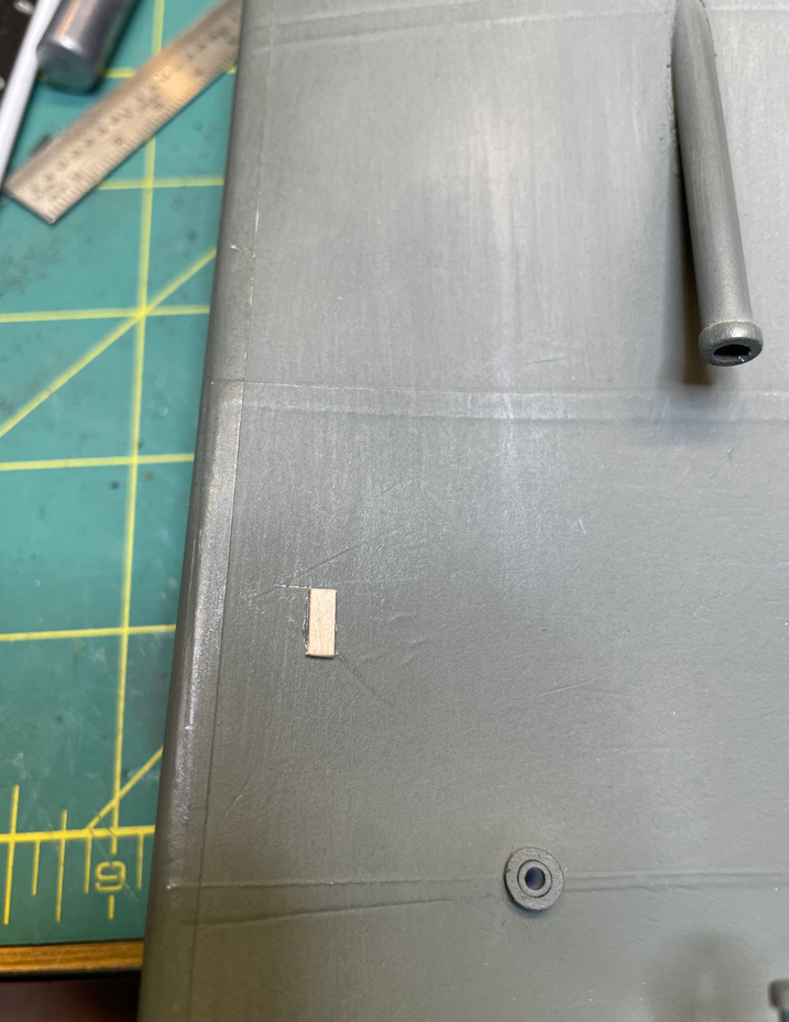
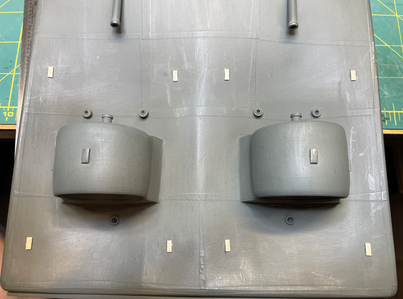
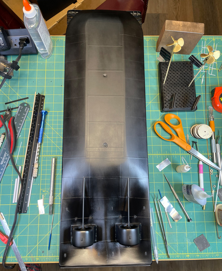
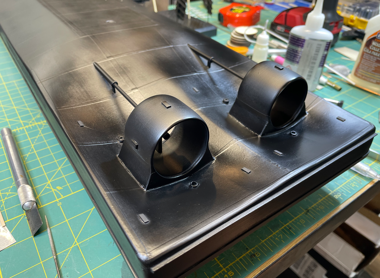
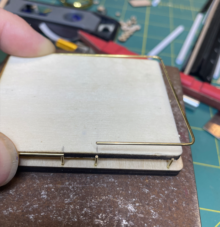
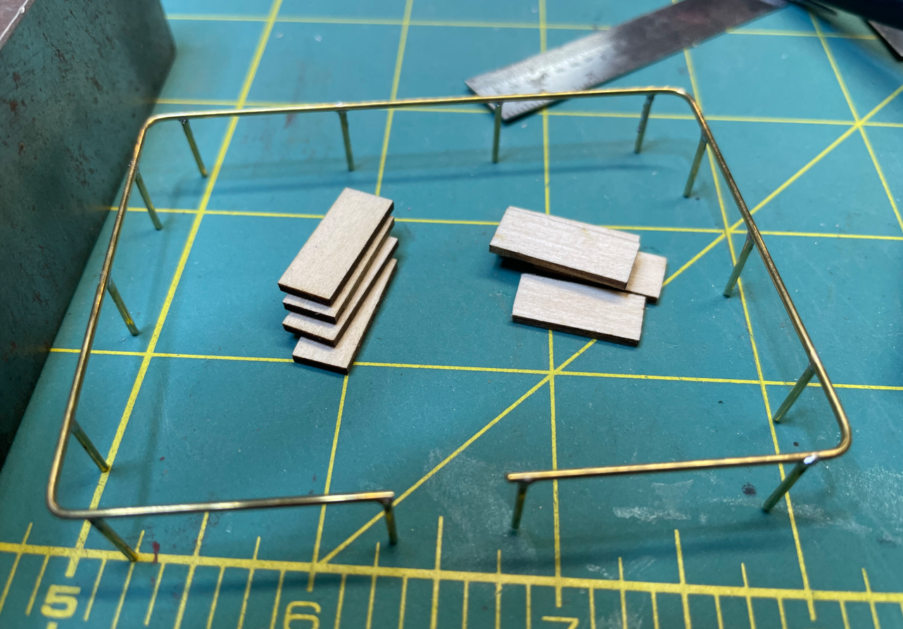
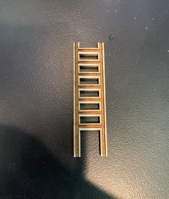
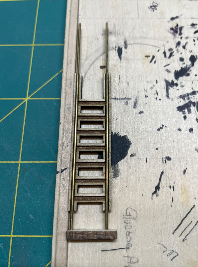
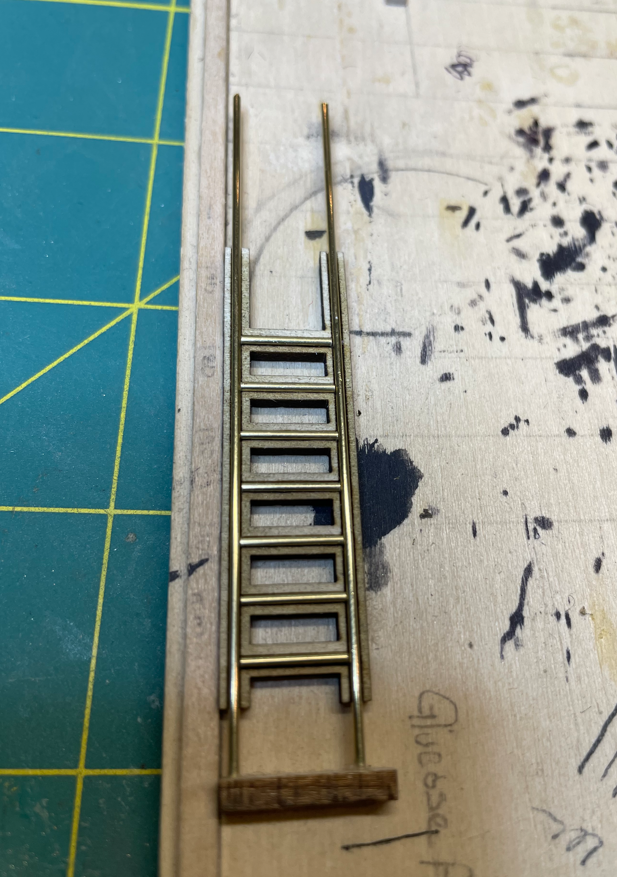
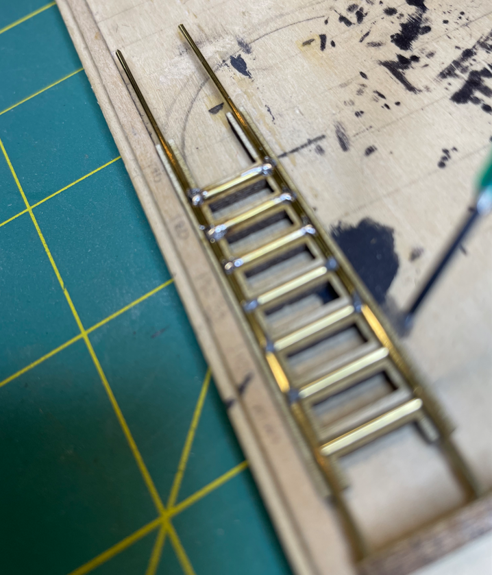
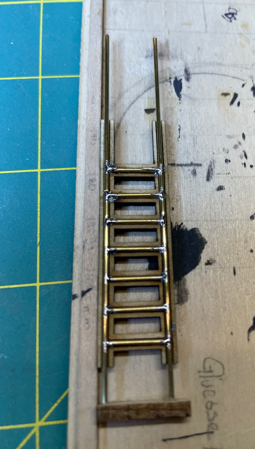
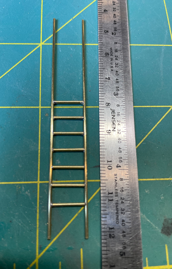
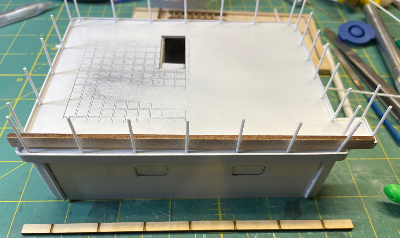
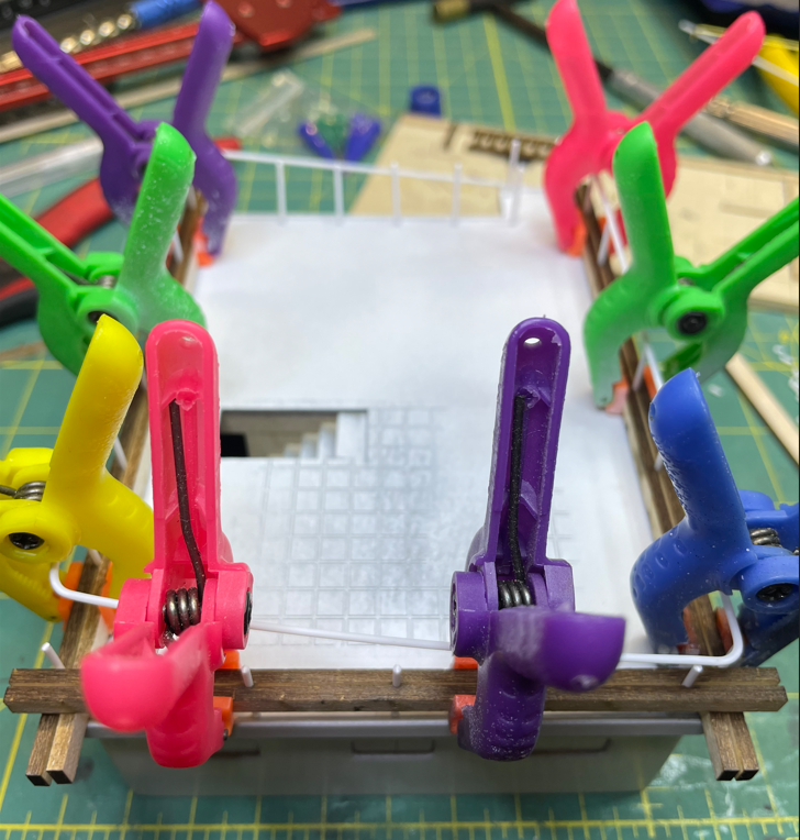
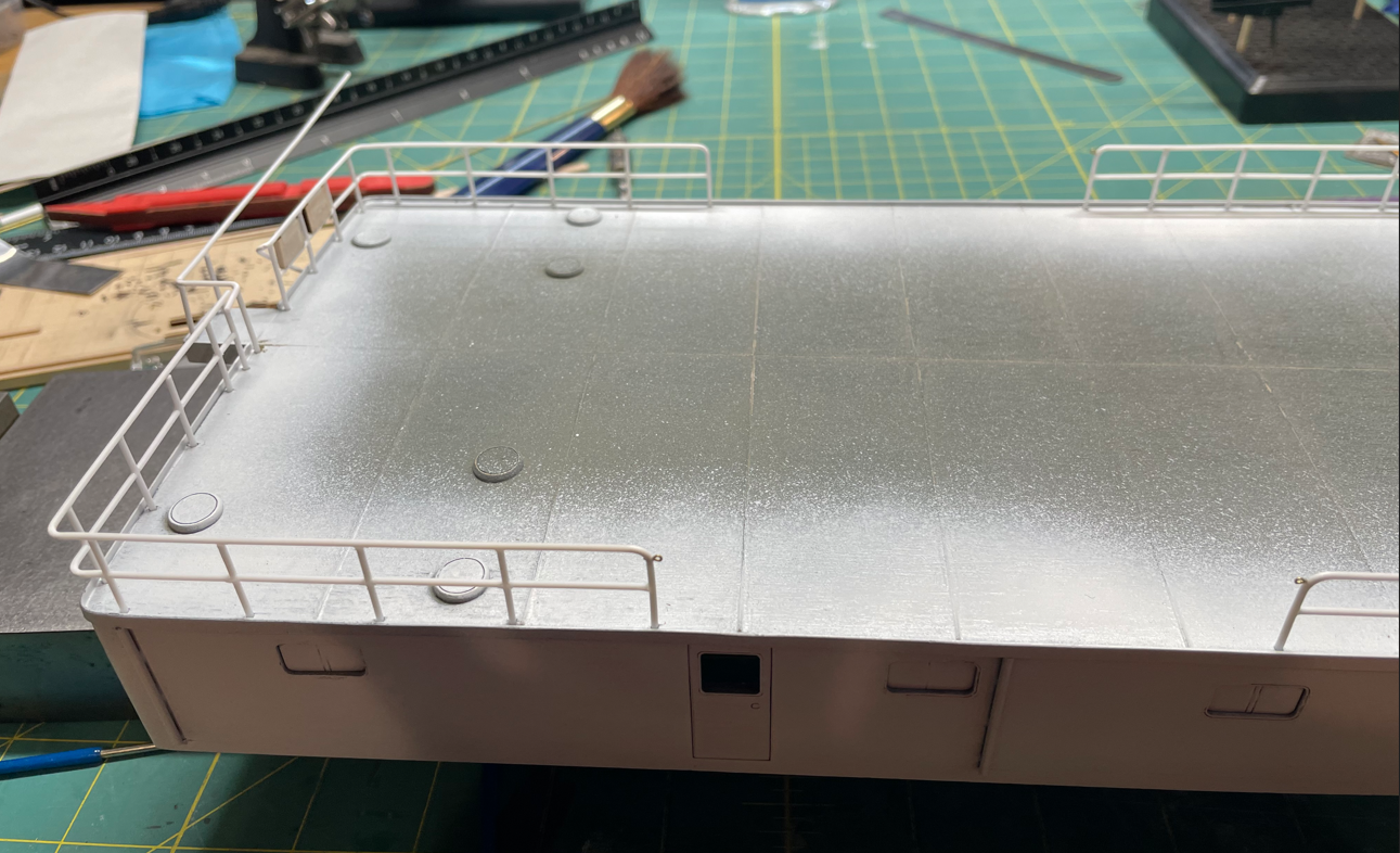
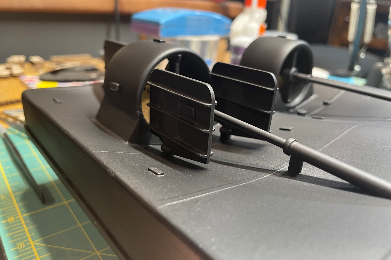
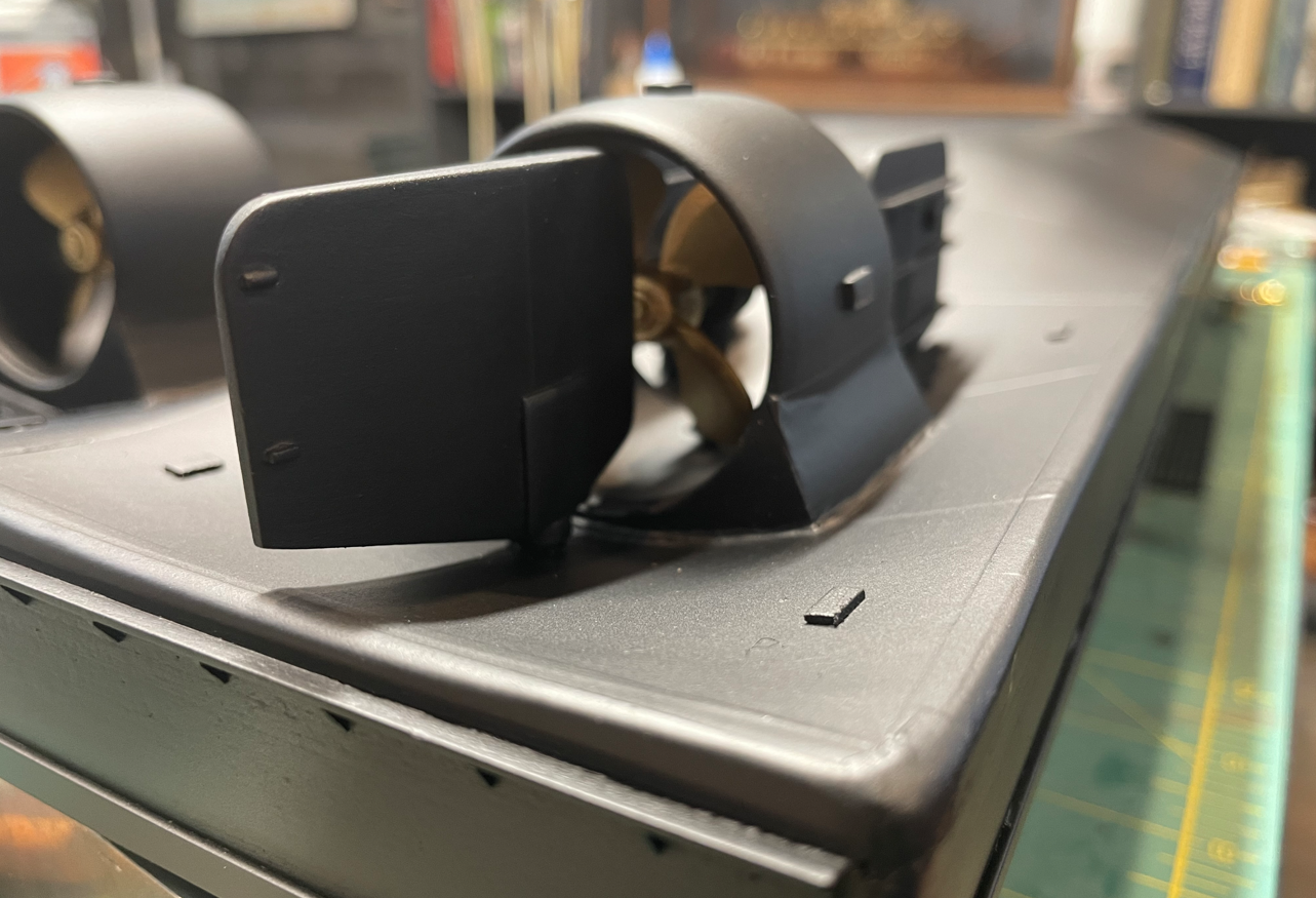
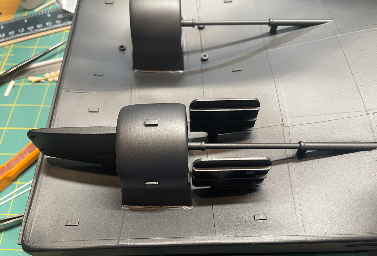
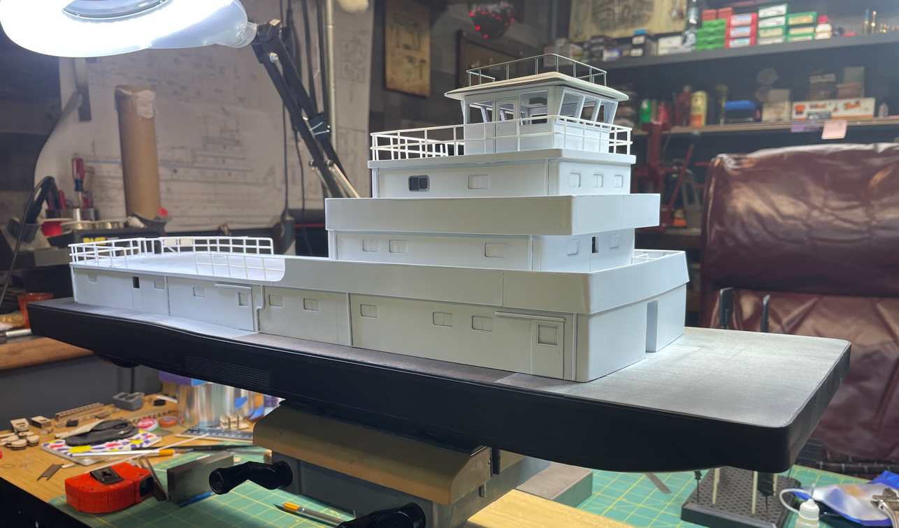
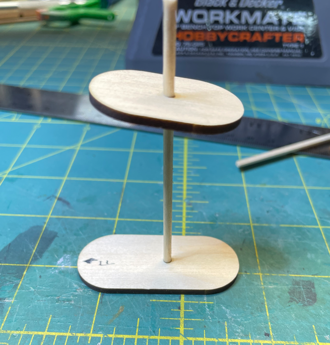
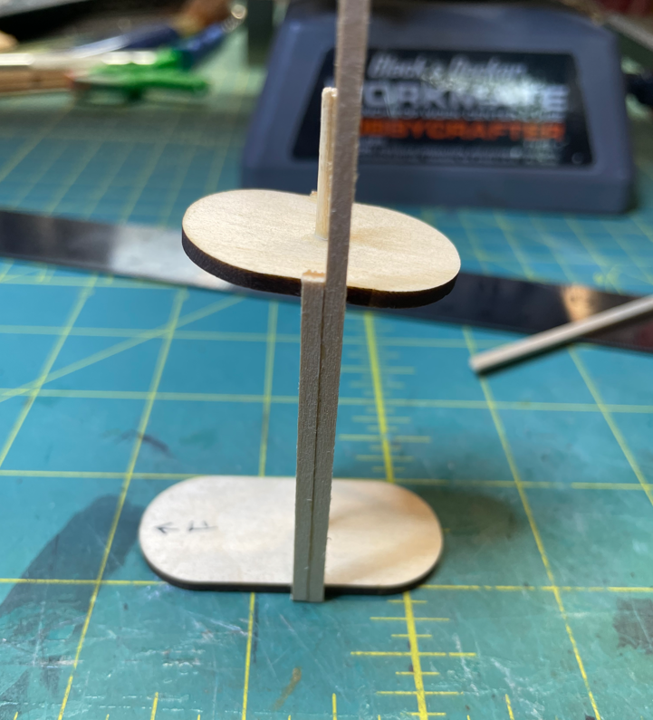
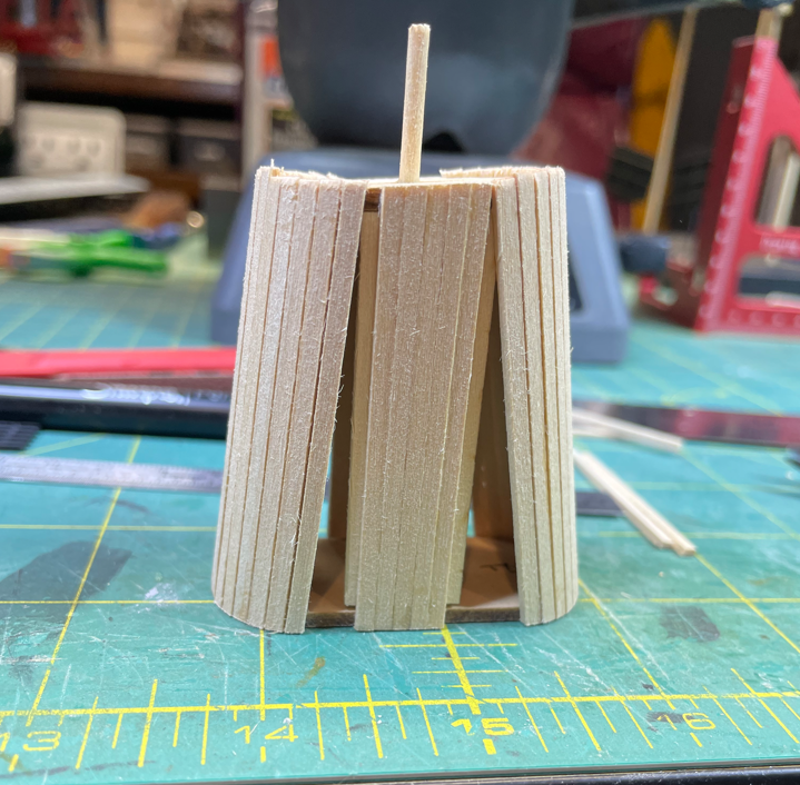
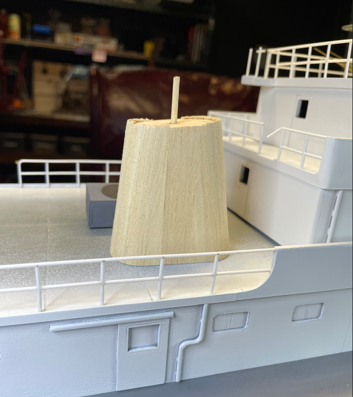
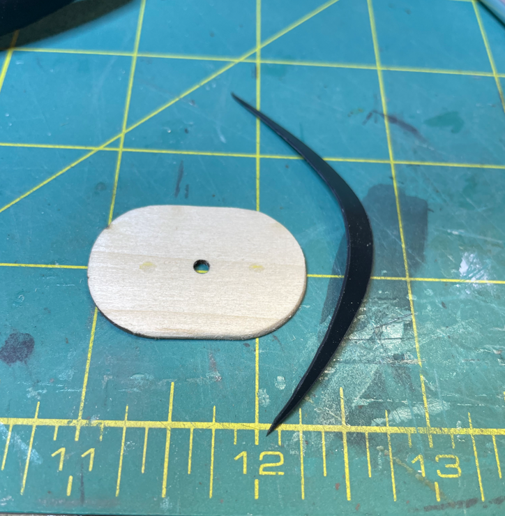
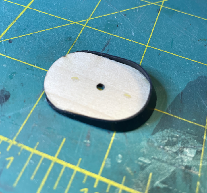
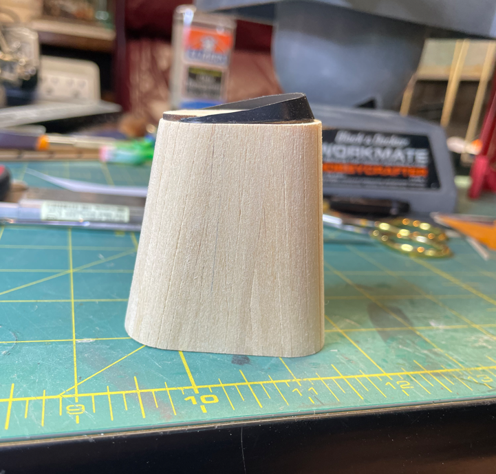
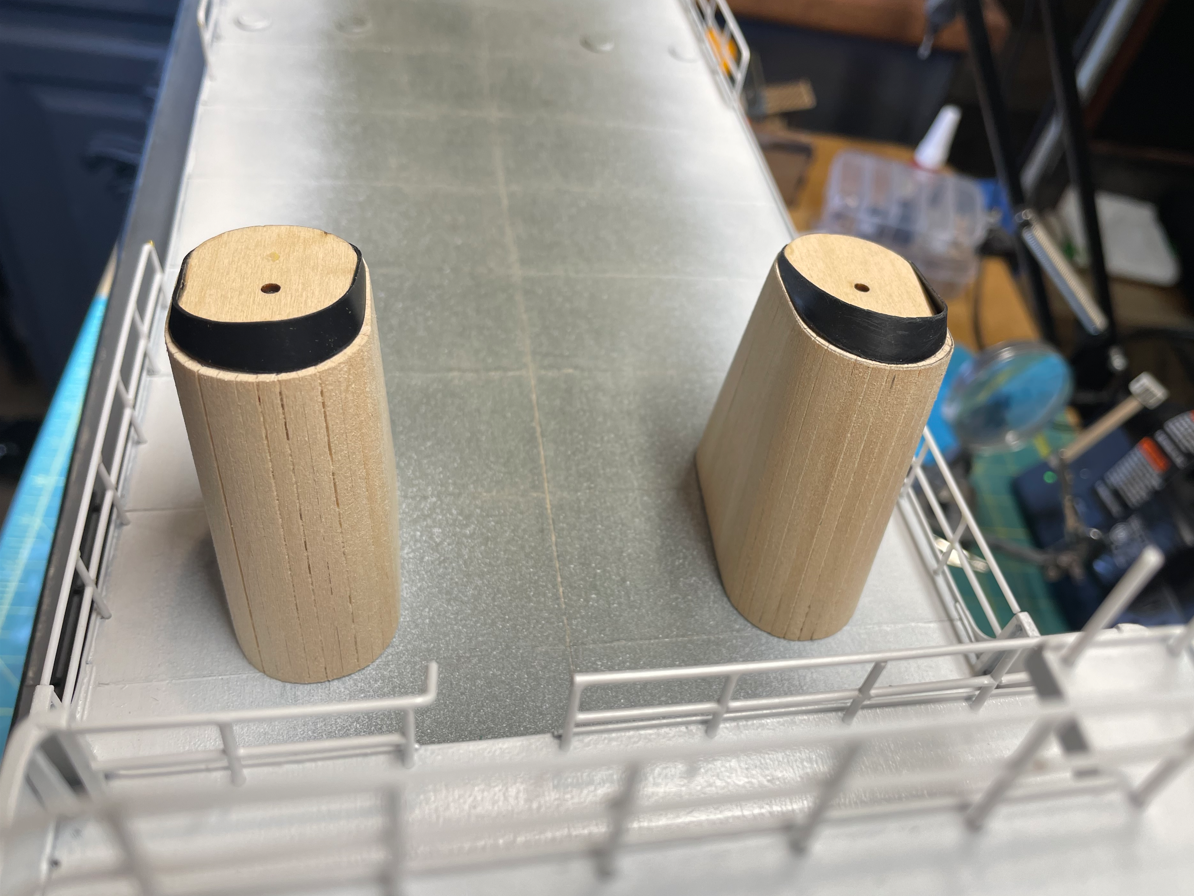
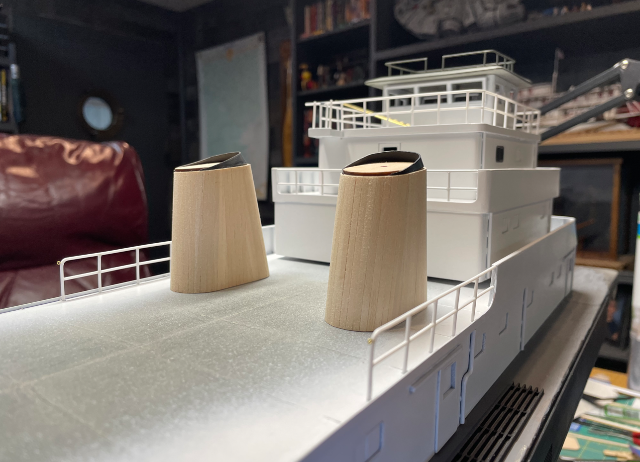
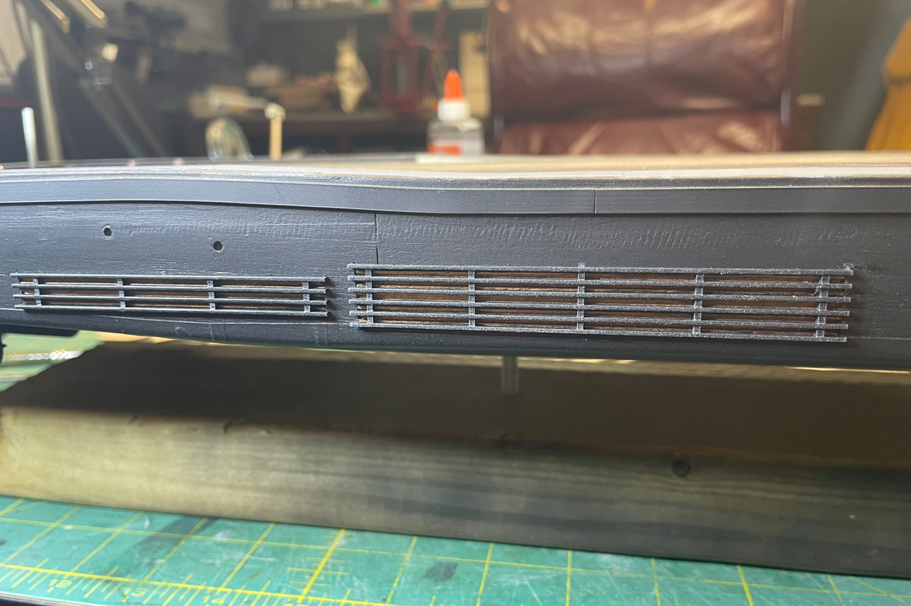
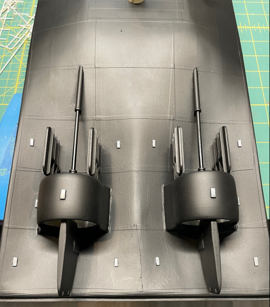
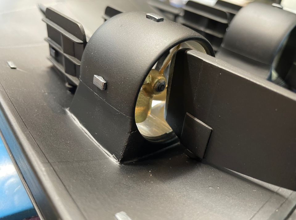
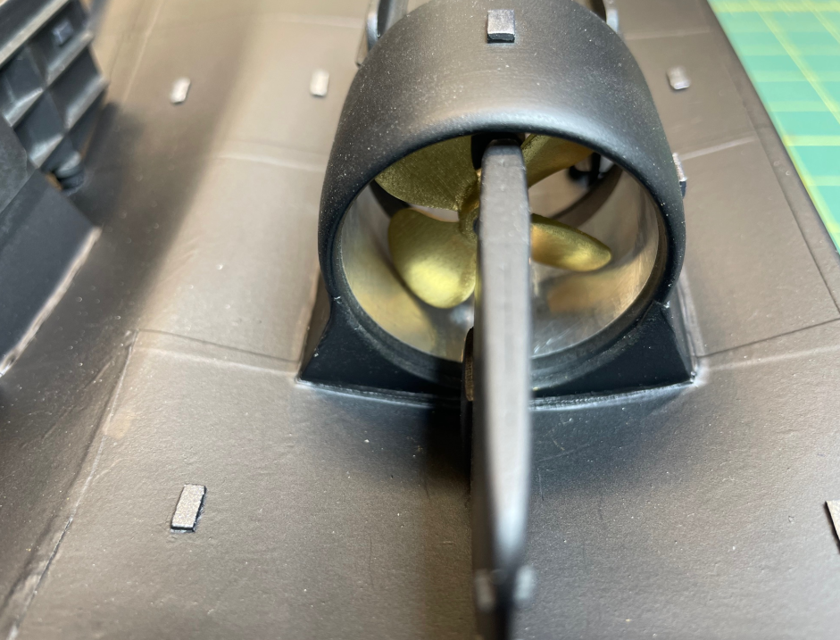
Hello again everyone, it has been way too long since my last update. I have been busy, I have just been dealing with computer problems. My old laptop decided to give up the ghost so I had to purchase a new one. Well after being a Windows guy for 30 years, I finally converted to the dark side and got a Mac. I knew there would be a learning curve to get used to a new style of computering, but it took me little longer than I had planned to get things moved over from my old laptop and figure out how to use the new style of apps. But I persevered and finally got it all moved over and I am ready to go. So pull up a chair, grab a drink and get ready for a major photo dump of progress. So on my last update I was having difficulty trying to solder my railings and had decided to go with the styrene method. While I pondered how to do the small railing on top of the pilothouse, I worked on the lower sections of railing. Here is the railing that surrounds the pilothouse going together. I couldn't get the small jig that I had previously made up to get a consistent results, and I was having a hard time getting the stanchions to stand straight up. So I made up a different jig that had slots cut in at the correct spacing and clamped the two halves together. This held the vertical stanchions perfectly upright and steady while I glued the top rail in place. Once this section was complete I removed the section of railing, placed it on my mat then used a small piece of scrap wood cut to the correct spacing to add the lower rail. I forgot to take pictures of this part, but in the next picture you can see a couple of the pieces of scrap wood on the railing show how it was spaced. More of the lower deck railings. Then it was on to the smaller railing. I took @KeithAug advice of making a jig with my Xtool to frame up the ladder as a test piece. So far so good. Then I cut the brass rod pieces and placed them into the jig. I decided to give the solder paste a try, and it didn't let me down. This was so much easier than trying to flux and solder the pieces together in the jig. After a little filing and cleanup I am very pleased with the outcome. Since the ladder was a success, I decided to use the solder paste on the pilothouse railing. For this one, I made up another jig that gave me the proper spacing for the height of the rail and soldered each stanchion one by one. Again, I am completely satisfied with the results. Now I'll just need to tie the ladder in with the railing, but that will have to come once I get the decks secured in place. After competing the railing, it was time to work on the hull features. I wanted to get everything on the underside of the hull done so I could get it mounted to a temporary base and work on everything upright. So I started with the Korts and wheels. On my previous post I had already cut and shaped the Korts and temp mounted them in place. Now it was time to install the fairings where they tie to the hull. Nothing out of the ordinary here, just cut a few pieces of wood sheets to match the contour of the Korts and hull. Then I made a couple of plugs with centering holes so that I knew where to align the wheel shafts. The centering plugs also helped me mark where the wheel shafts will penetrate the hull. Once the penetration points were marked, it was time to do a little drilling. Wheel shafts temp installed to test their alignment. Then the wheel shafts were cut and mock wheels made to make sure that I had the centering and clearances correct. Once the holes were drilled and the shafts cut, it was time to work on the shaft supports. I cut out several pieces to layer up the supports and carve them down. Three layers was just about right, now its time to carve them down. Roughly shaped, and testing the fit. This is the look that I am going for. On to the wheels. I used the mock patterns that I had previously made to align each blade. I made the hub in the same manner that I made the supports. I cut out several layers and sanded them to shape. I didn't take pictures of this process as well, but you can see end results of the hubs in this photo. I then cut out another pattern of the wheels and separated the blades from the hub and proceeded to glue them at the proper angle on the shaped hubs. One of the completed wheels. And temp installed in the Kort. Just a little sanding, shaping and paint and they should be good. Next it was time to work on the rudders. I started with the main rudders. These were cut from pieces of wood sheeting. I didn't have any materials thick enough for the completed rudder so I layered these as well. Here is the initial shape. The two layers glued together. Shaping to get the correct contour. Rudders temp installed to test their alignment. I also threw in another little detail with the addition of a galvanic anodes. These were place in various places along the hull, rudder and Korts to help with corrosion prevention. Time for the flanking rudders. Same process, these were also cut out of wood sheets, but there is not any contour to these. They are fairly flat and need to have a narrow profile since they are rarely used when the boat is going forward. This low profile reduces drag and prevents the disruption of water flow through the Korts. There is some cross bracing to help stabilize any flex from the water flowing across it. Here is the initial pattern. Cross bracing installed. More bracing. This is used to streamline the water flow around the rudder shaft. More galvanic anodes installed on these rudders as well. All four rudders completed. While perusing the internet for more study material I ran across an another little detail that was built into the boats. I'm not sure what it's called and my searches were coming up empty, but that is not saying much because its sometimes hard to look something up if you don't know what to call it. Anyway, I noticed from some of the videos of towboats in dry dock that there was this fairing attached to aft section of the hull. My best guess is that its purpose is to help keep the turbulent water from coming over the aft deck. So I glued on a thin strip of wood and installed these very tiny gussets cut from .020 ABS sheets. Here are the gussets. Gussets going in. The finished fairing Time to get it all premiered up and ready for some paint. And more galvanic anodes going in. Next up was the installation of the coil coolers. These were radiators of sorts installed on the hull sides that uses river water to cool copper fins that circulate engine and clutch oil through. The coolers are mounted recessed in the hull and a protective grill installed on the outside to protect the fins from river debris. Here are the cooling fins that I cut out on the laser cutter. Recesses cut into the hull for the cooling fins. Fins installed in the hull Here is the protective grill alongside the hull and coolers. These will get attached after the hull is painted and the cooler fins coated with a touch of copper paint. Painting of the hull, wheels and rudders. Flanking rudders installed. Main rudders temp installed to test for clearance. Port rudders aligned All rudders installed and anodes painted up. Up close shots showing details. Time to flip it over and install the coil cooler guards. It wasn't until I posted this photo that I noticed the gap in the wood planks on the hull. I'll need to go back and fix that. Here she is in her correct, upright position with all decks sitting in place. One final feature that was almost completed that I wanted to add to this update was the construction of the stacks. I started with a basic framework of a base and top with a center support to maintain the correct height of the stacks. Then it was time to cover the frame with strips of wood. Here is the first strip going in. More progress. Starting to take shape. Completely covered with a light sanding to smooth out the edges of the planks. Here is the cap and fairing that will sit on top of the stack The two pieces assembled. And the cap installed on the stack and a final sanding. Both stacks completed and temp installed. Another view. I will take these and cover them with some body filler to fill in the gaps and give the top pairing its final shape. Hopefully that will be done by my next update . Well that is it for this update, I hope to be a little more timely with my next one. Thank you all for sticking with me on this and stopping by. As always I appreciate all the kind words and input. -Brian
-
Very nice progress Eric! I agree with Keith and John, she is truly beginning to look like the photos of her and your work on the canvas looks great. As for your paddlewheel, that is one of my favorite parts to build. Just the details that go into them add to the beauty of these boats. -Brian
-
If I said this never happened to me and you believed it, we need to talk about some ocean front property in Arizona that I'd like to sell you . It may not have happened on the tarpaper roof, but I have made this mistake in other areas on other builds. At least with the masking tape it's a little bit easier to repair. With silkspan and Modge Podge there is a lot more sanding involved. Great job on the recovery though John. -Brian
-
USS Cairo by Zetec - 1/50 scale
mbp521 replied to Zetec's topic in - Build logs for subjects built 1851 - 1900
Beautiful work as always John! Glad to see more progress. I would have to say that the paddlewheel was one of the more complex parts of the build, but also one of the most enjoyable and satisfying parts. -Brian -
Thanks for the Maggie update Keith. Glad to hear she is progressing nicely. We’ll still continue to send healing prayers your way. Google is a wonderful resource for recipes, I’ve tried several out myself with some success. And happy belated birthday, hopefully you celebrated it with a nice long nap. 😁 -Brian
-
Looking good Eric. I may have to look into getting me one of those magnetic squaring jigs. Looks pretty handy. -Brian
-
Gotta love all those battens 😁. They really test your patience. Great work John! -Brian
-
Roger, I envy you and your master skills with soldering miniature pieces. -Brian