.JPG.3b858ae7db6d3e5e48507bb4328943a5.JPG)
jlefever
-
Posts
156 -
Joined
-
Last visited
1 Follower
Recent Profile Visitors
966 profile views


.jpg.d84ec4dad1d7791e855dca06210ab6f3.thumb.jpg.f45209242e851d4409eca1a09293165b.jpg)
-
 BETAQDAVE reacted to a post in a topic:
Phantom 1868 by victory78 - New York pilot boat
BETAQDAVE reacted to a post in a topic:
Phantom 1868 by victory78 - New York pilot boat
-
jlefever reacted to a post in a topic:
Smuggler by juhu - FINISHED - BlueJacket Shipcrafters- 1:48
-
 Roger Pellett reacted to a post in a topic:
Modeling a seine boat for the mackerel fishery
Roger Pellett reacted to a post in a topic:
Modeling a seine boat for the mackerel fishery
-
bruce d reacted to a post in a topic:
Modeling a seine boat for the mackerel fishery
-
longshanks reacted to a post in a topic:
Modeling a seine boat for the mackerel fishery
-
Elia reacted to a post in a topic:
Modeling a seine boat for the mackerel fishery
-
Canute reacted to a post in a topic:
Dremel rotary tool?
-
The Proxxon tool sounds interesting, but I have used a Dremel for years. I use it for drilling wood, plastic, brass and white metal and generally find the mid-range speeds handle the finest high-speed bits wonderfully. I had used the traditional pin vise but with my too heavy hand was constantly breaking bits, with the Dremel, I can work quicker and almost never break a bit. I also use it with a cut off wheel or drum sander to shape metal and occasionally with a dental style burr for wood carving (although it's not as capable as I'd like). I suspect hand-held it wouldn't work well for something like a rabbit. Jim Anchors shaped from 1/16" brass with various Dremel tools.

-
 Looks like a solid model and things are going well. Keep up the good work. Jim
- 37 replies
-
- 1
-
-
- Glad Tidings
- Model Shipways
- (and 1 more)
-
A really nice project. Looking forward to seeing it finished. JIm
-
Looking good. I'm enjoying following your work. Jim
-
Looking nice and clean, keep up the good work. Jim
- 37 replies
-
- 1
-
-
- Glad Tidings
- Model Shipways
- (and 1 more)
-
Even with good filters, there are plenty of sources of dust in a home, carpet, furniture, skin and hair, pets... notwithstanding the exterior sources such as northwest trees or here in southern CA, winds, traffic and your neighborhood brush fire. If you want to keep your model in good shape, some sort of dust cover seems a good investment. In my case, the case also affords extra protection from the family cats. I think a nice cover can even enhance the model presentation a bit. ...of course, unless you are really handy with plex or glass a case can be pretty expensive. My general sense is that with a decent kit the orders of magnitude cost are about equal thirds: The cost of the kit. Paint, glue, added modeling materials and so on. The case Hope this helps a bit. Jim
-
Really nice fittings and finishes. Well on your way to a fine model Nils. Jim
- 180 replies
-
- 2
-
-
- pilot boat
- Elbe 5
- (and 3 more)
-
Nicely done! She will be a fine model. Jim
-
There's no reason you can't rotate the side elevation so that the keel will be parallel to the edge of your block, however since the station lines will not be vertical, but slightly rotated off plumb, the length of the plan drawn on top of the block will change slightly. It should get just a tiny bit longer but, perhaps not enough to cause a significant problem. Project the rotated station lines to the top of the block and across then check their spacing against these on the ship's plan. Jim
-
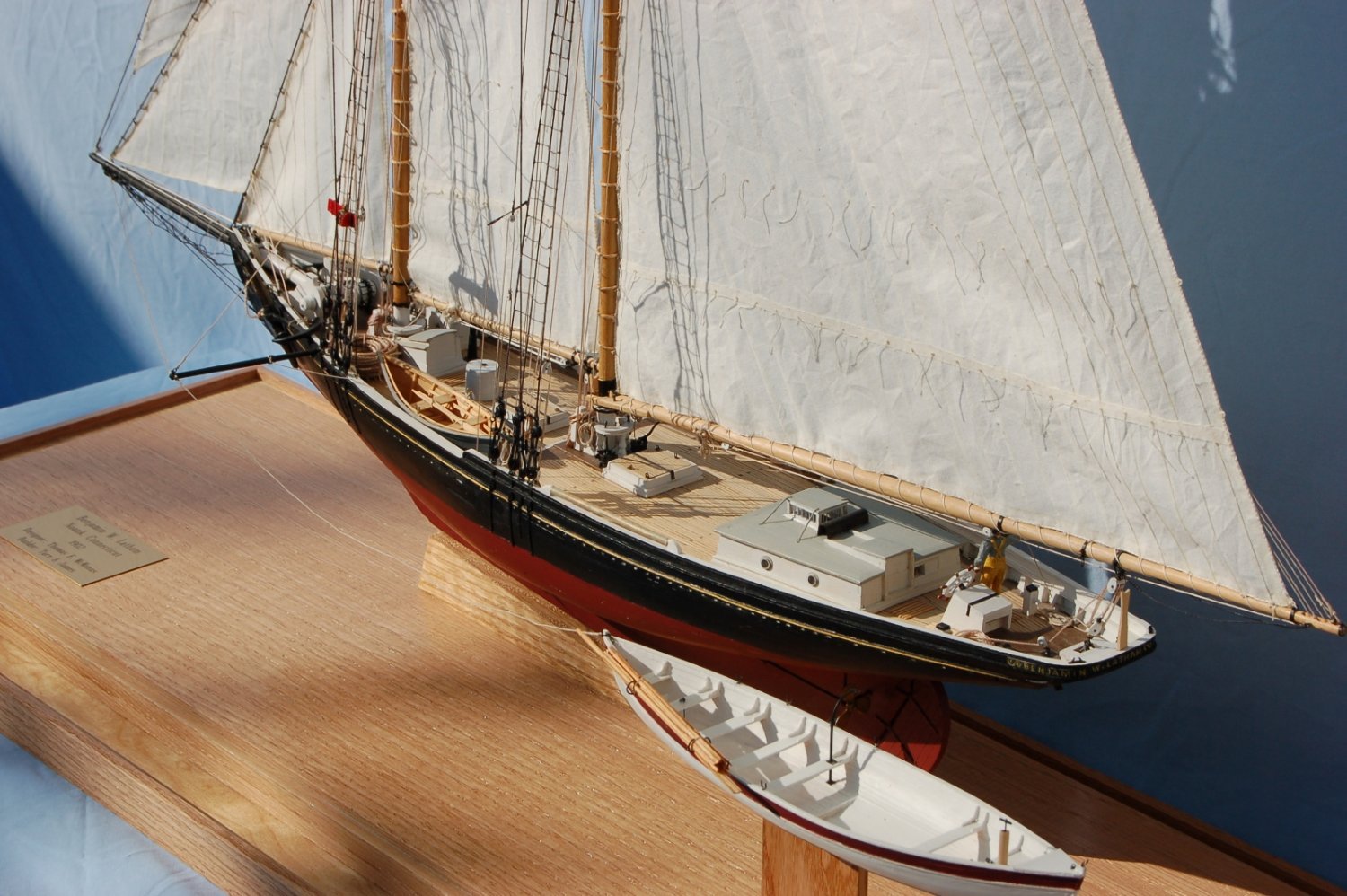
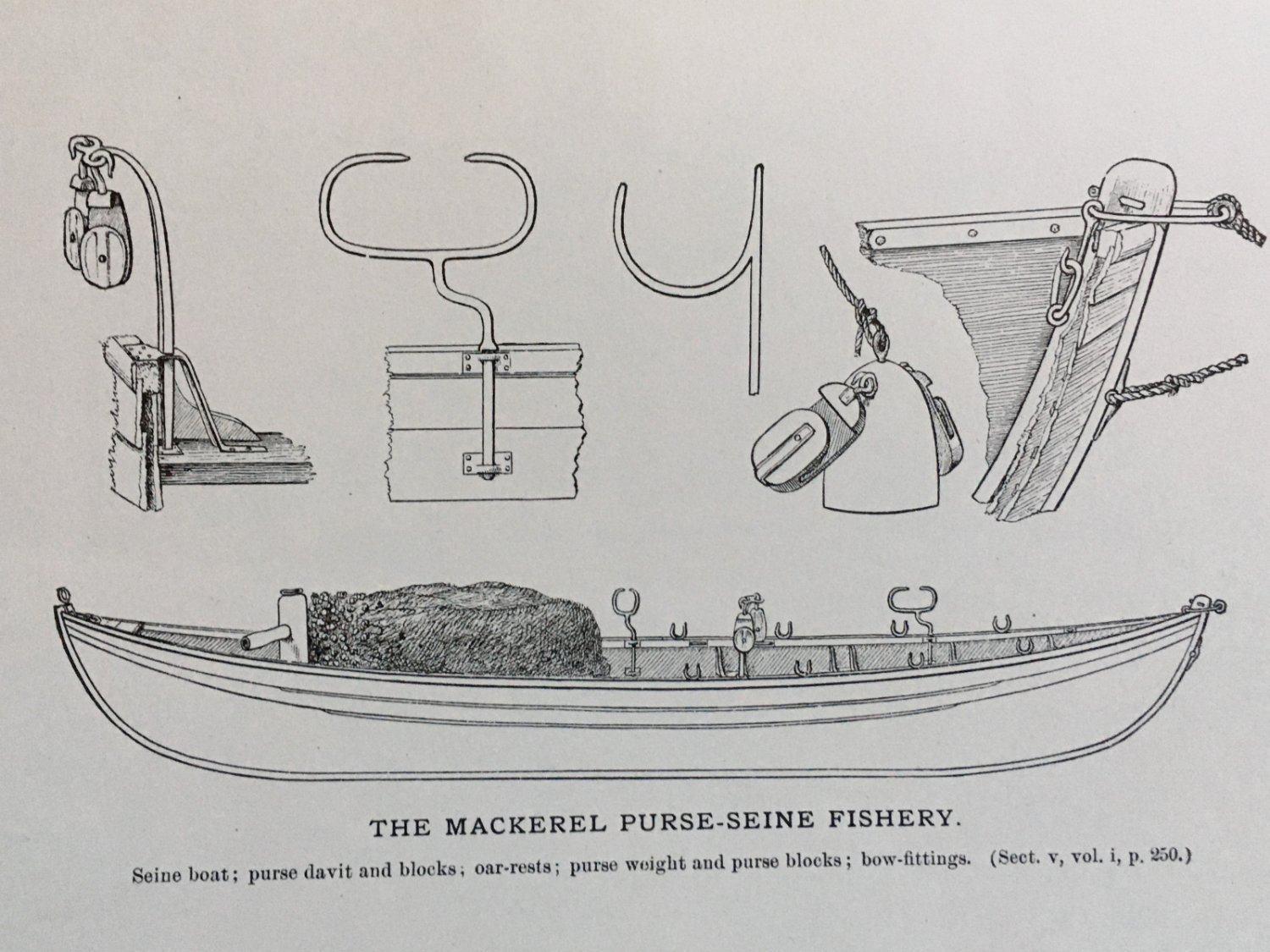
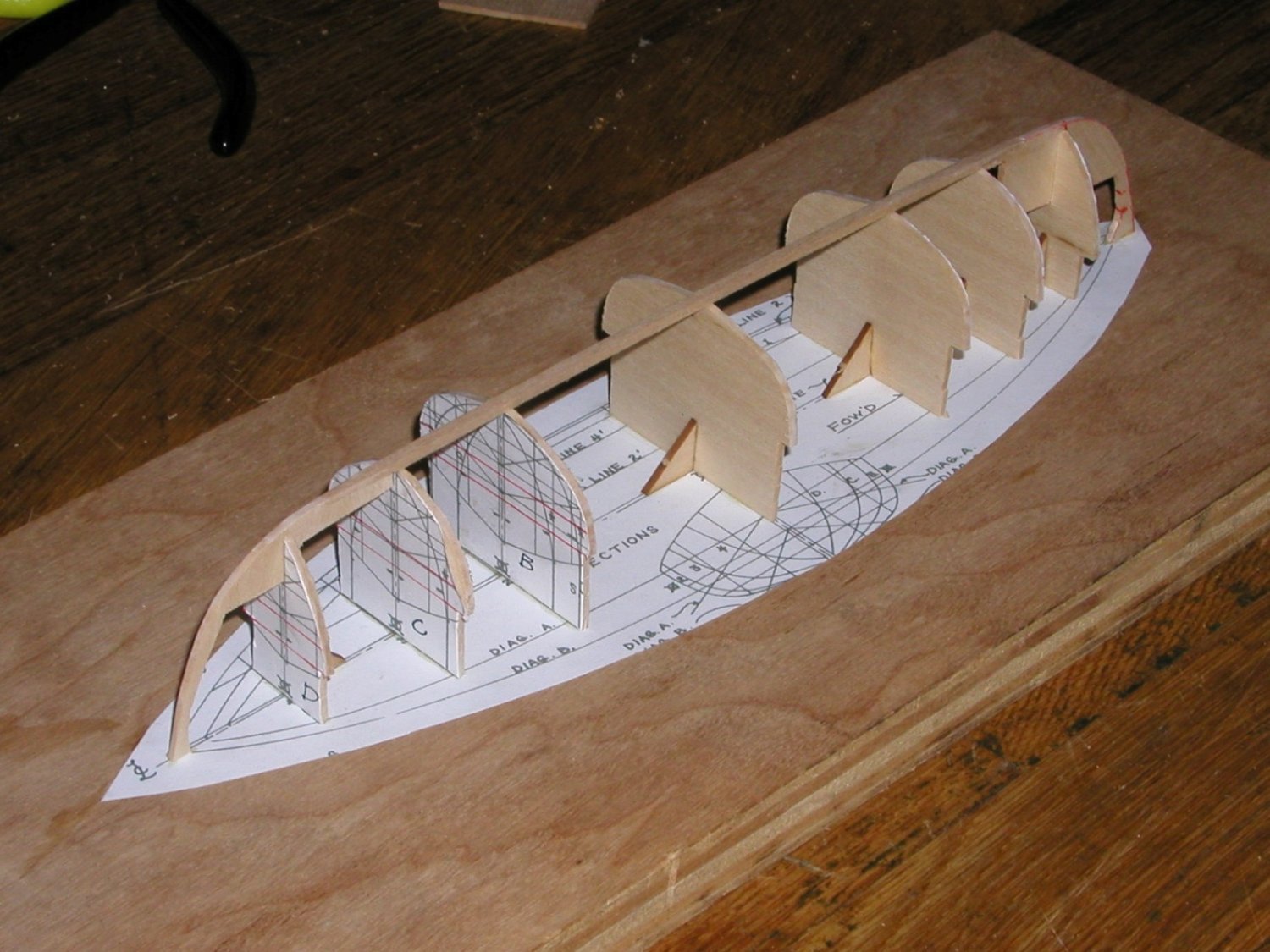
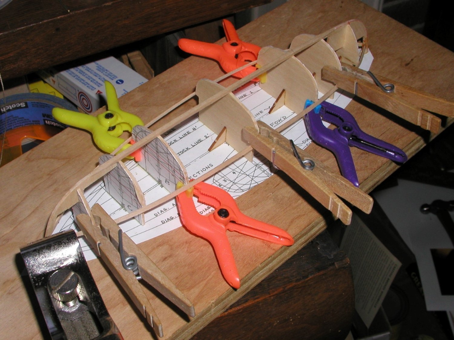
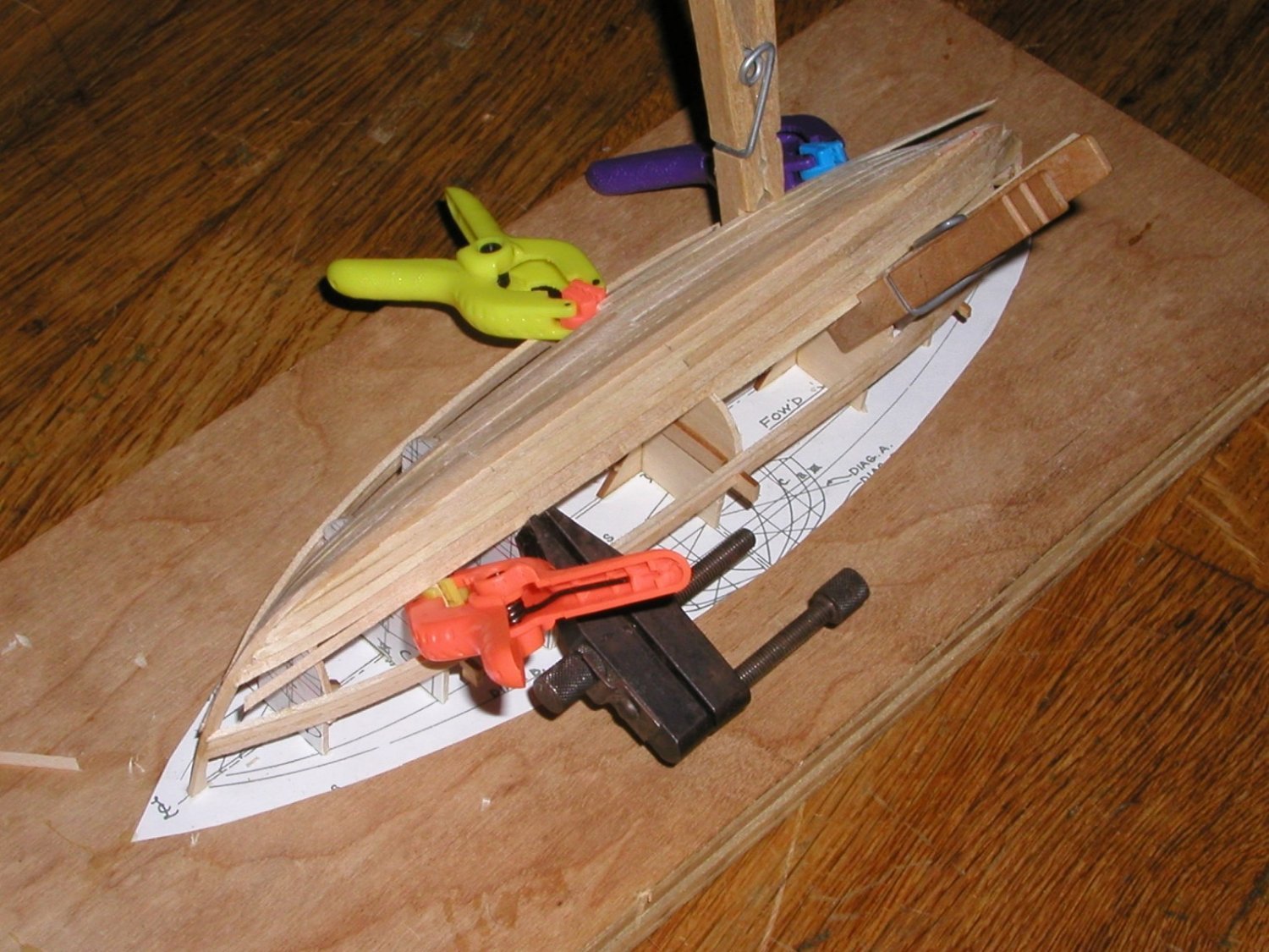
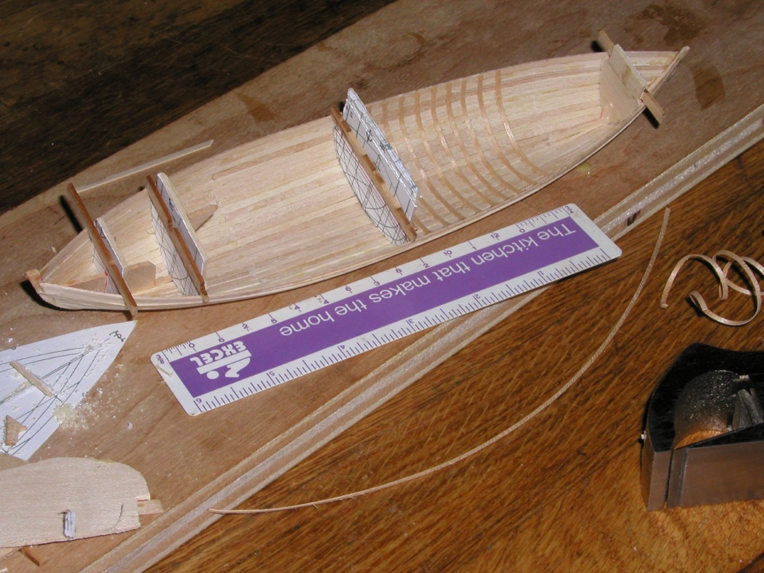
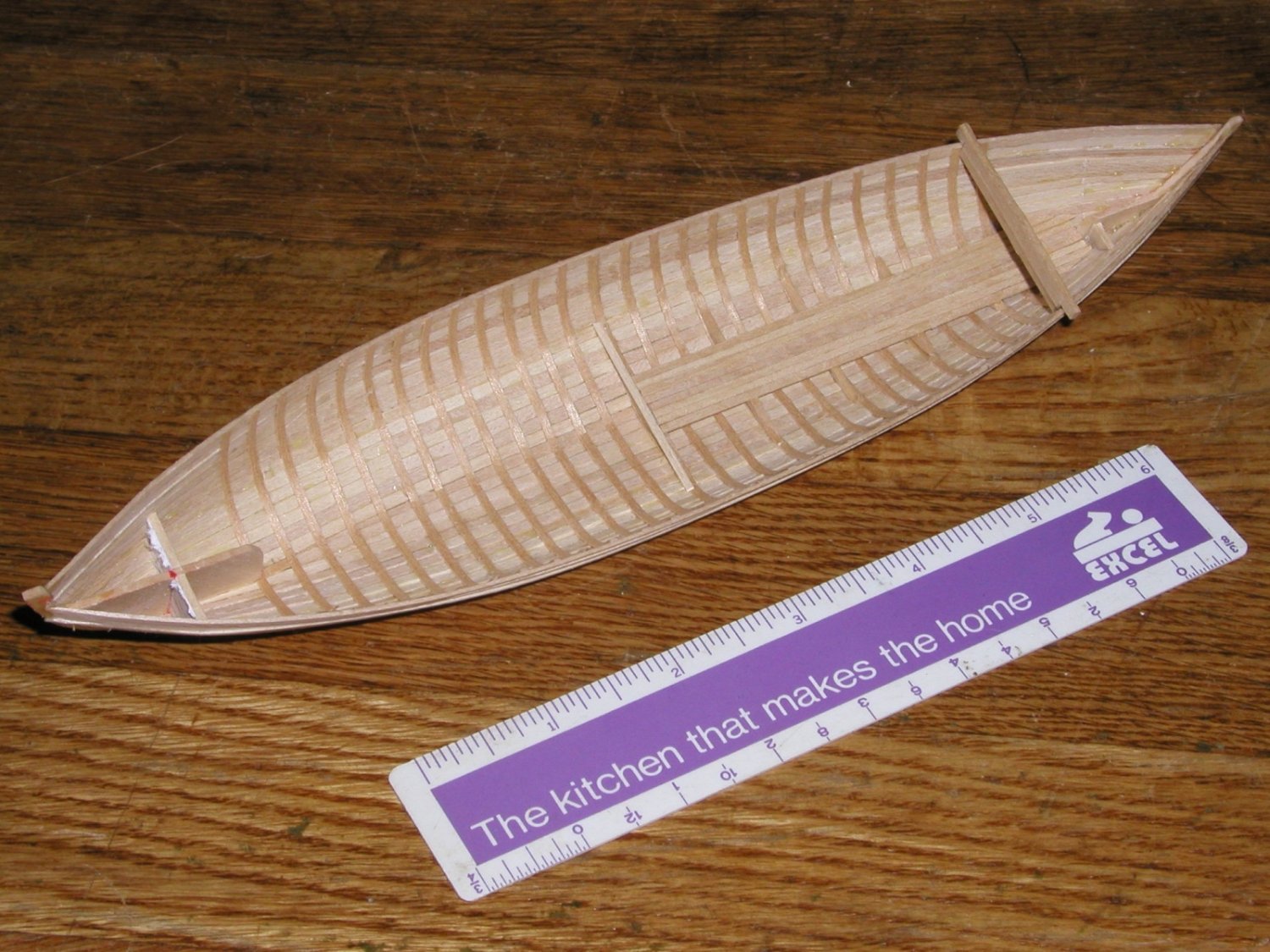
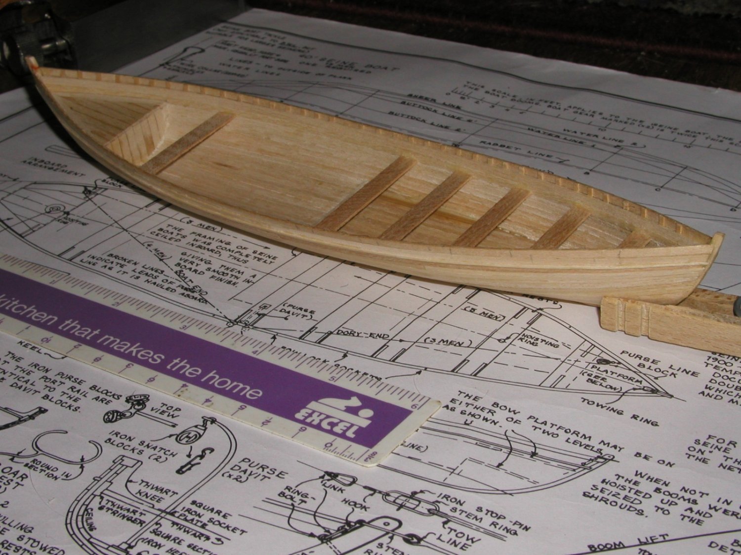
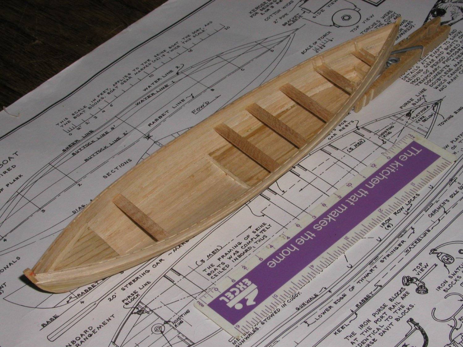
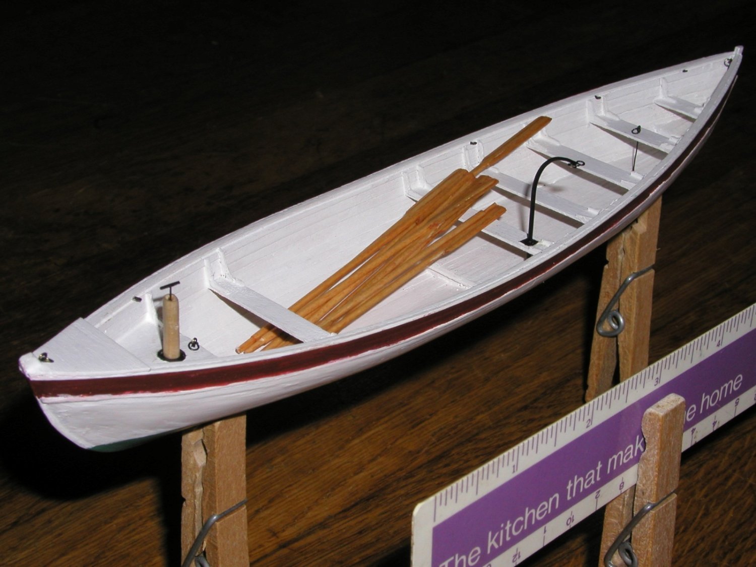
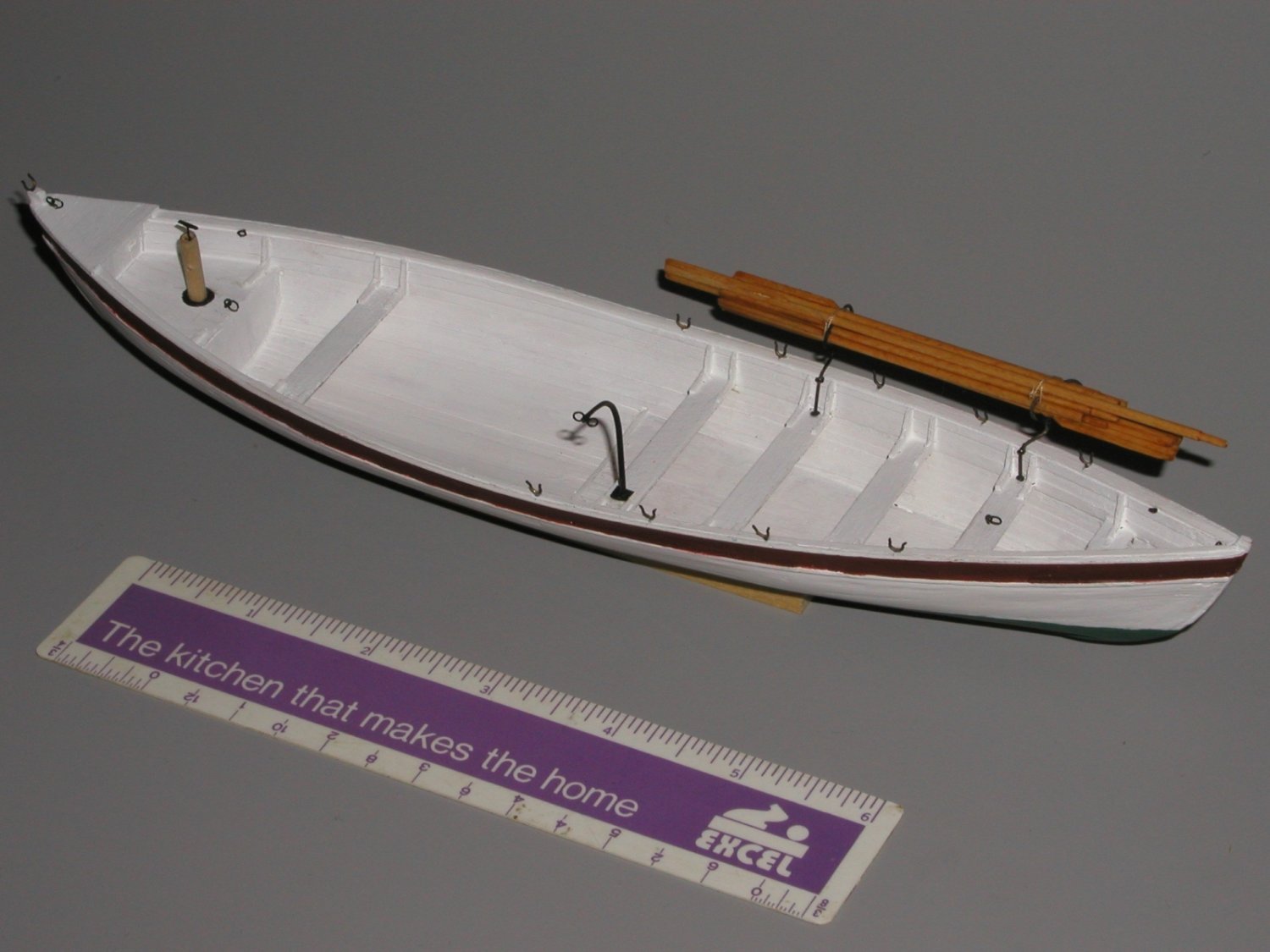
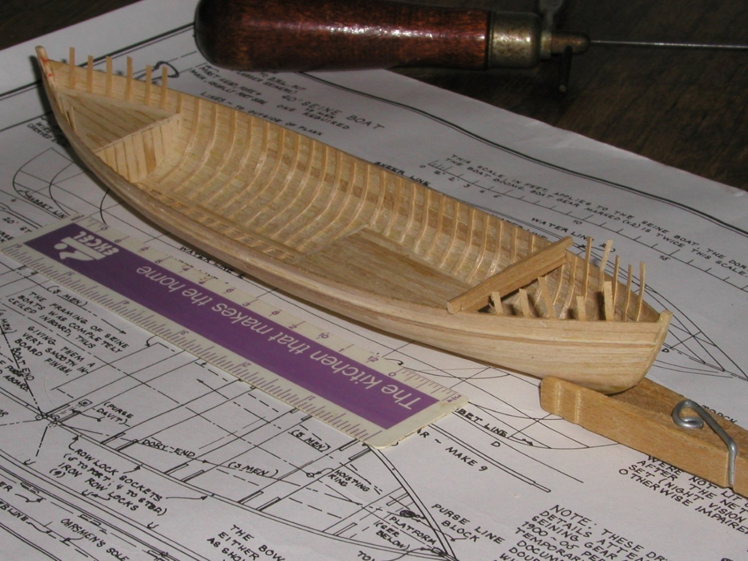
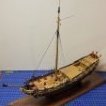
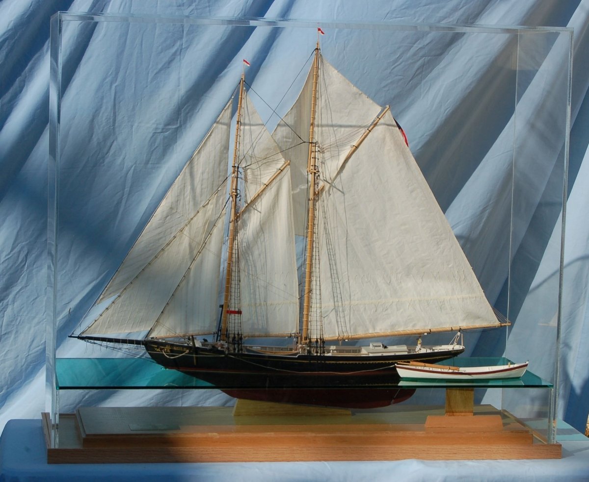
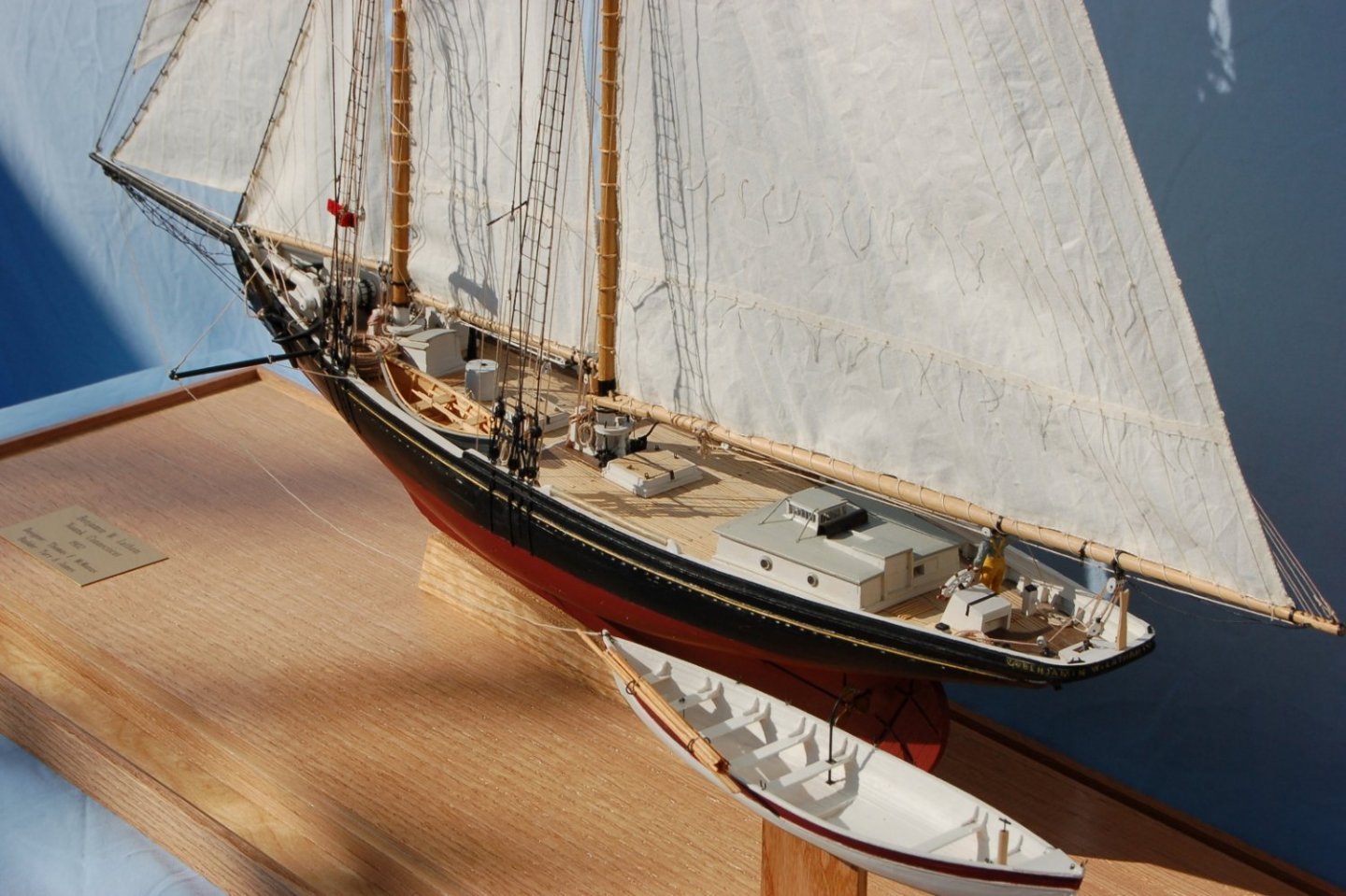
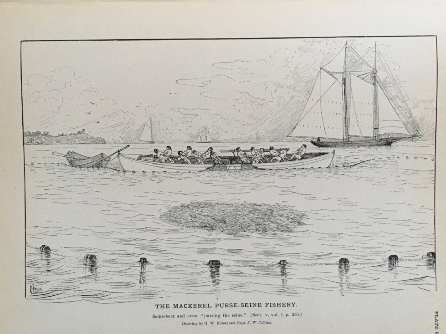
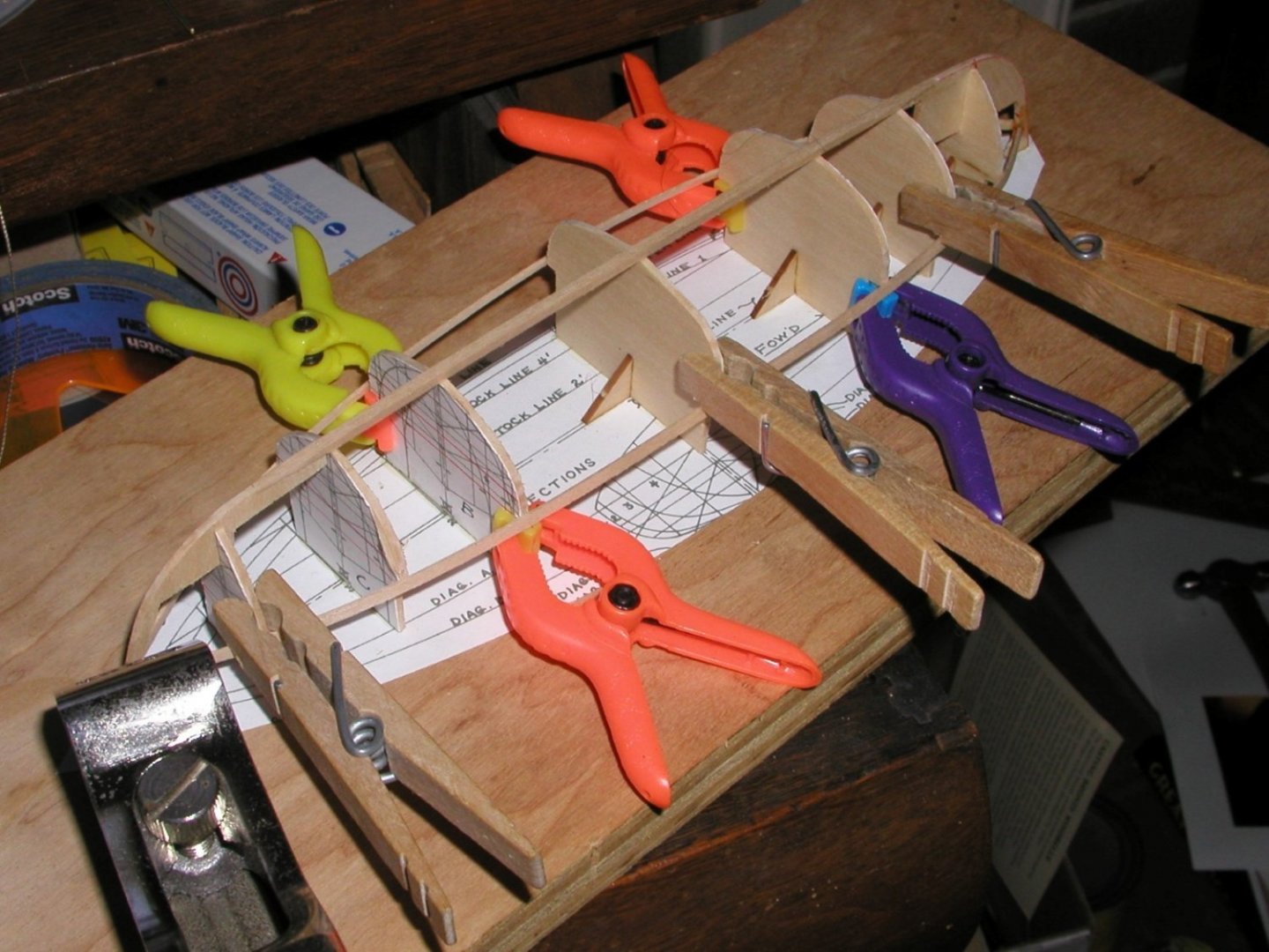
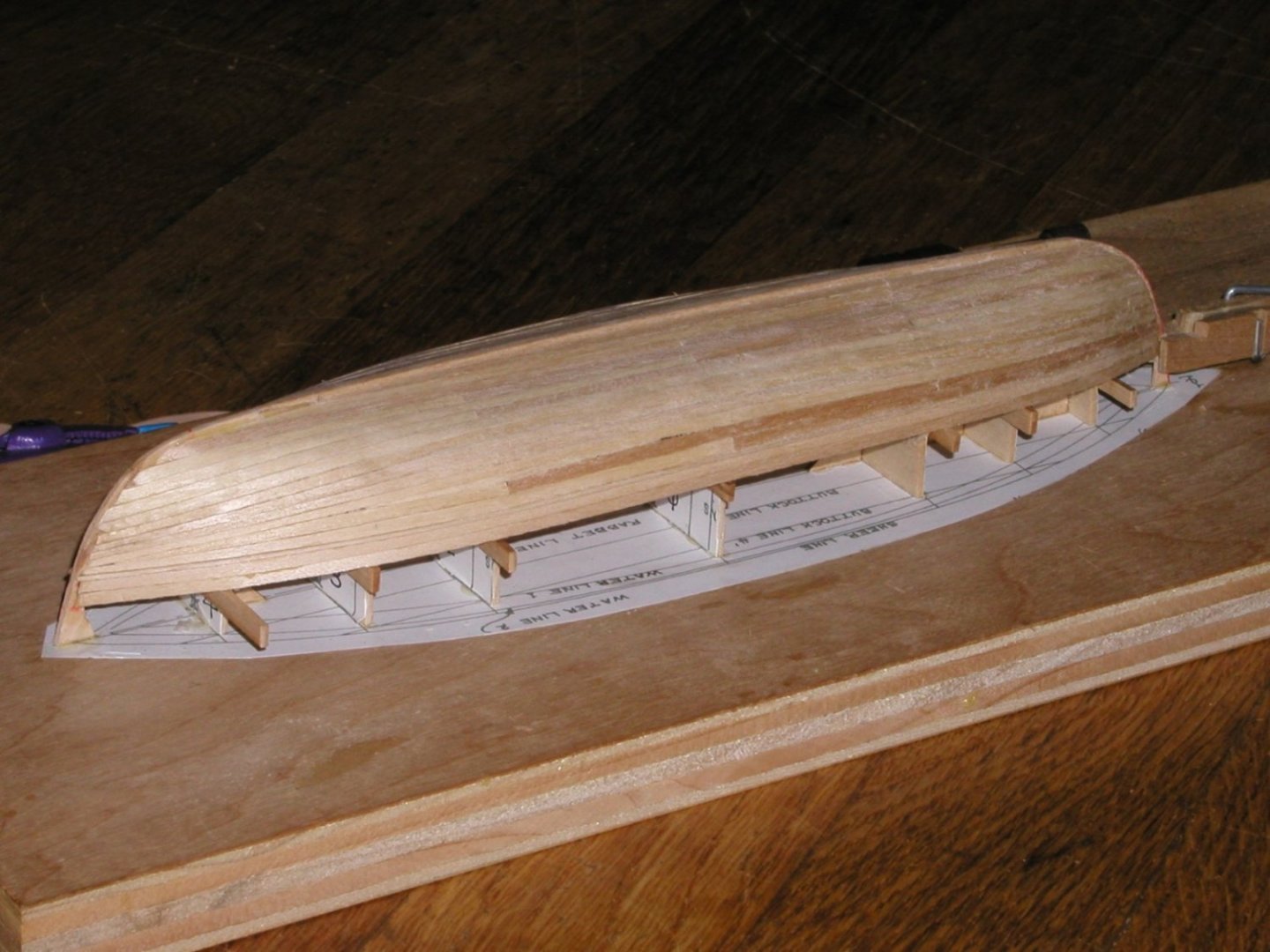
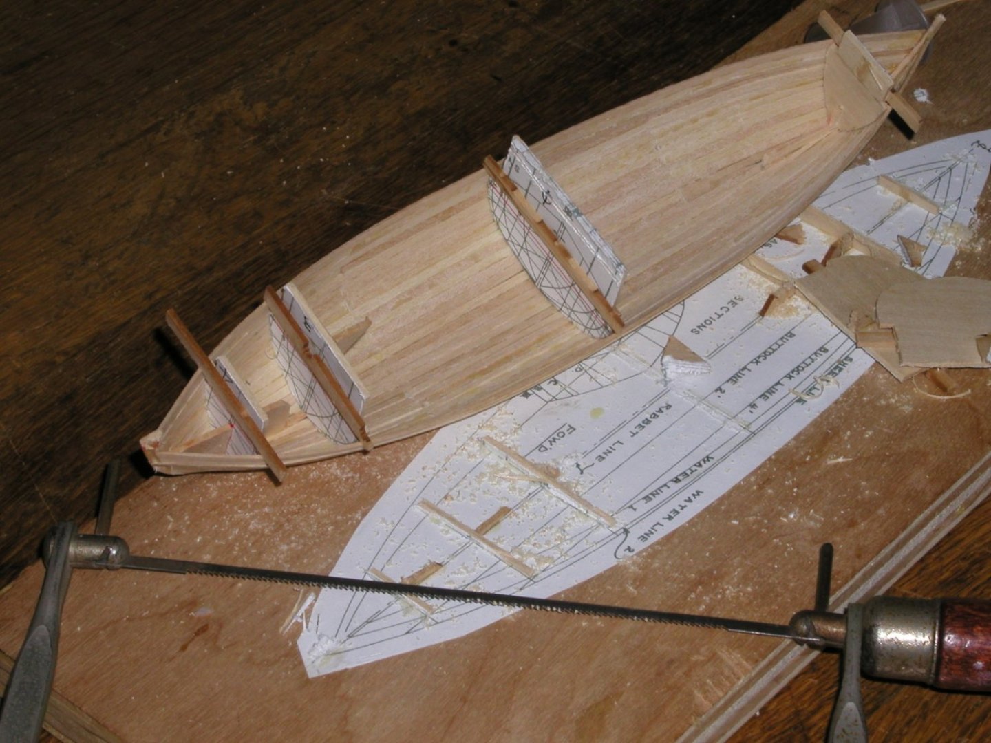
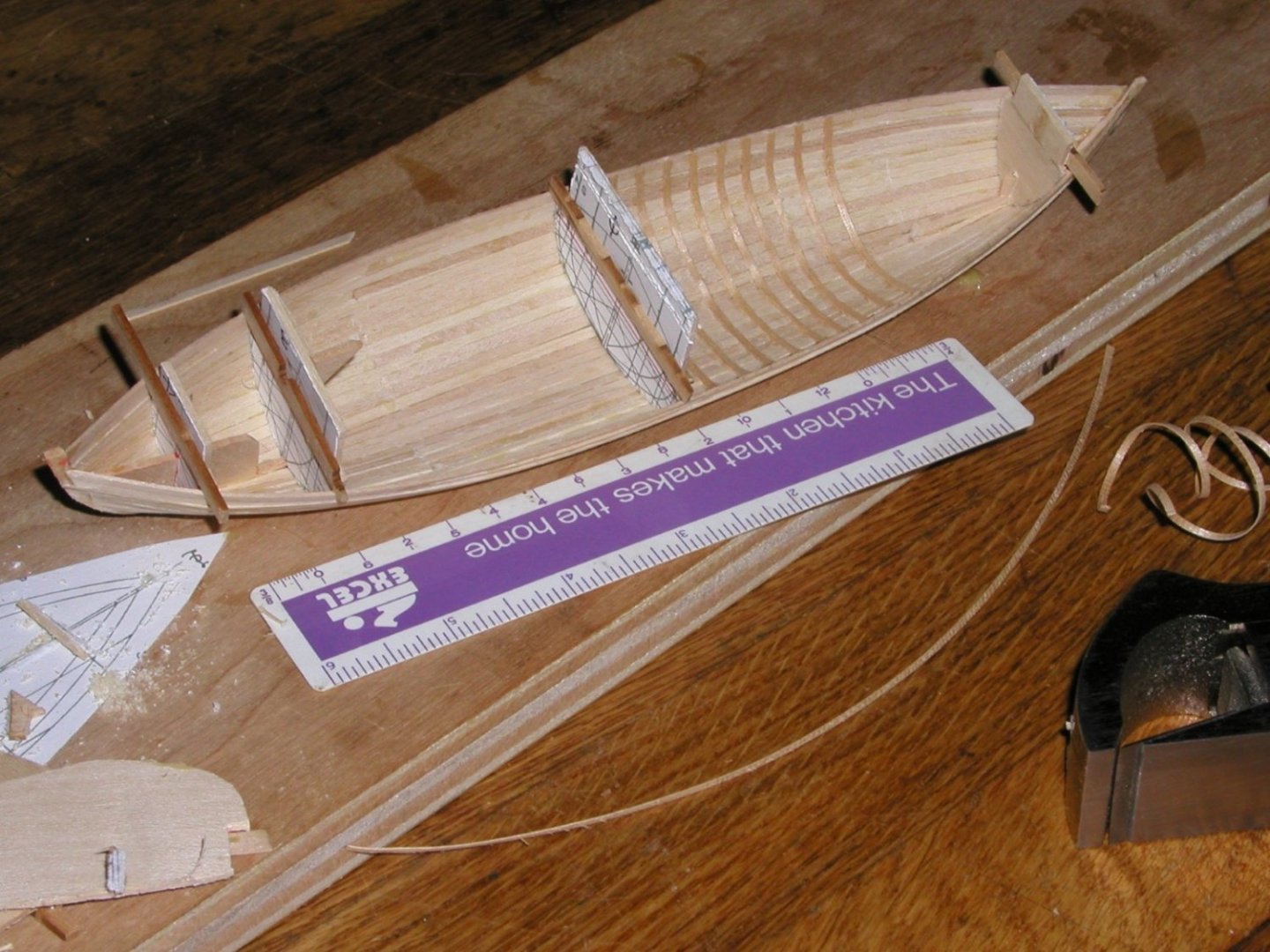
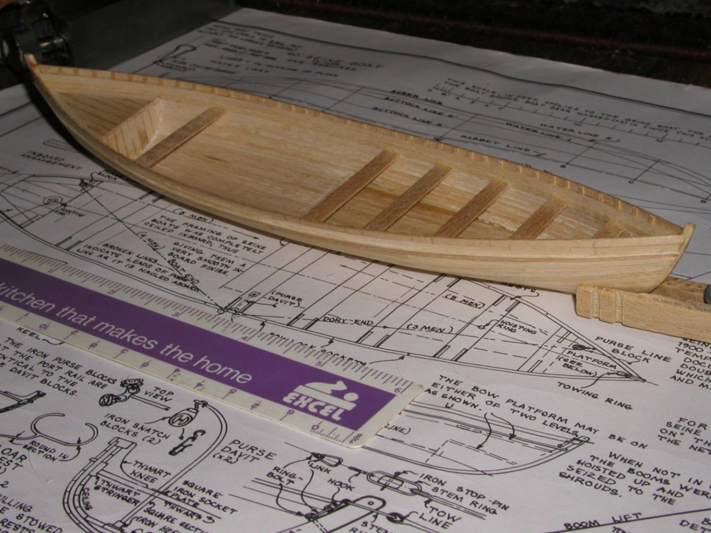
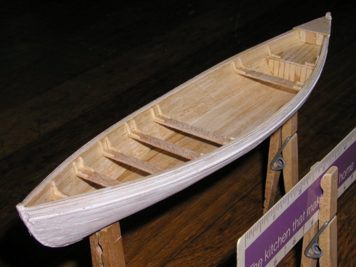
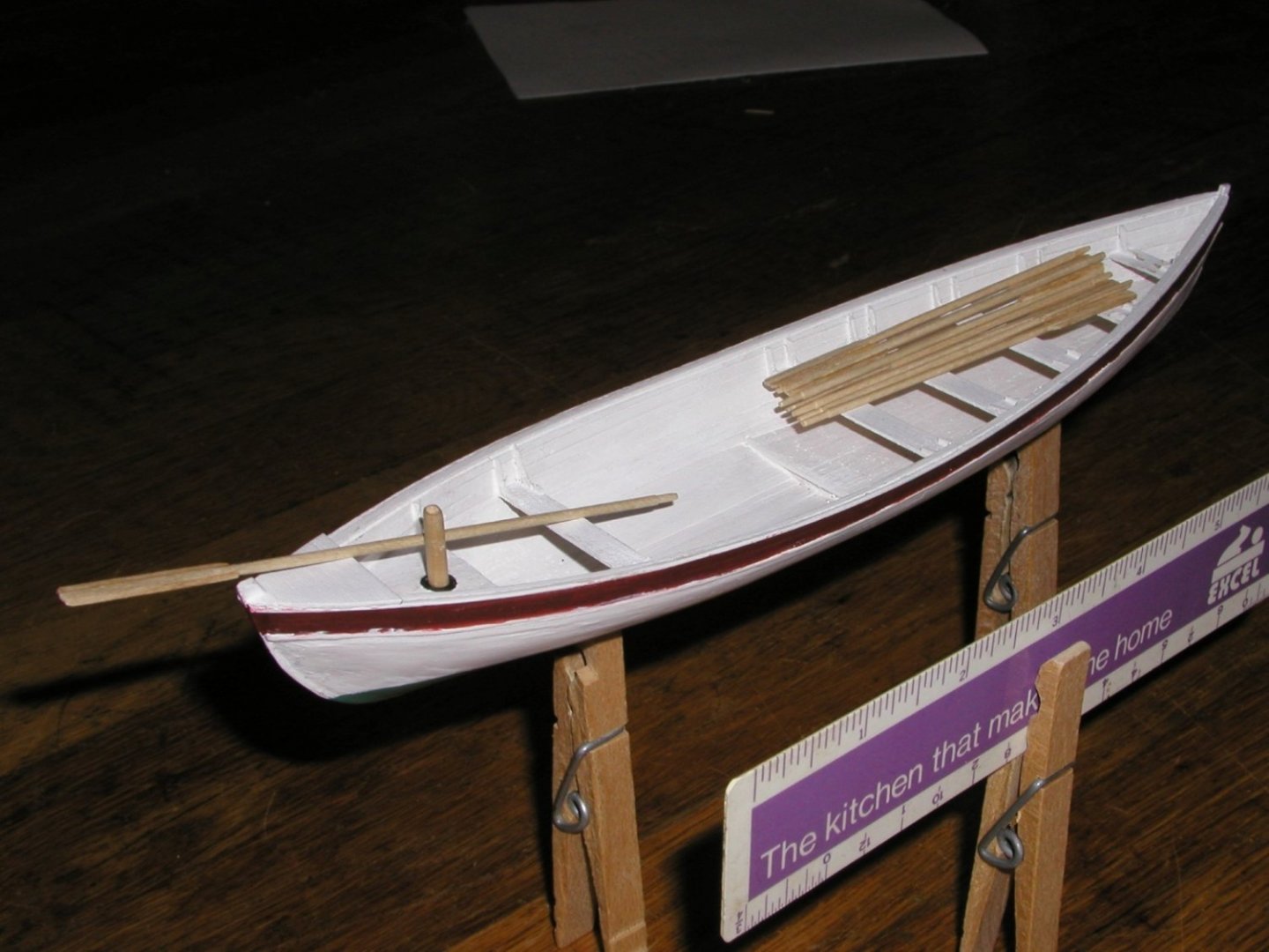
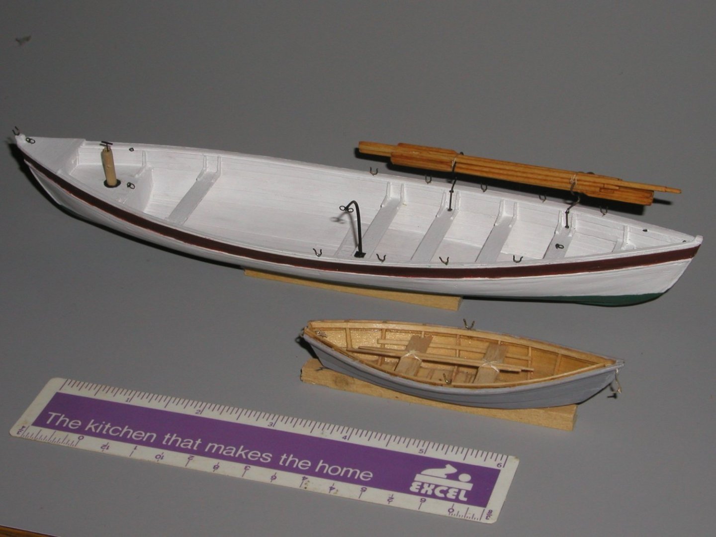
Several years ago, I built the Model Shipways Benjamin Latham and really enjoyed the project. I’m even fairly proud of my results (see link at the end of the article). I’ve noticed a number of Latham projects underway elsewhere on the site and that got me wondering if I could be of any help to other modelers. Since many of the Latham projects appear to be at least as good and some much better than mine I’m not sure what help I can provide. One thing I remember about building the kit was the instructions and materials provided for the ship’s boats were either below the standard set by the remainder of the kit or simply nonexistent. The plans for these boats included in the kit, on the other hand, were excellent. I had a lot of fun, basically scratching the ships boats so perhaps someone could benefit from my experience and discoveries. The Latham’s plans depict very typical boats that were used to work the purse seine net used in the mackerel fishery, a dory and a seine boat. The image above shows my Latham model with the dory aboard in the waist and the seine boat as it might have been towed. The kit instructions indicate that while bigger fishermen carried the seine boat aboard, the Latham was too small and her seine boat would have been towed to sea. A small error occurs here, the tow rope is too long for one used when offloading the days catch, the boat should be towed even with the roller on the rail, and too short for towing. The two following images come from a wonderful old book, The Fishery Industries of the United States, U.S. Commission of Fish and Fisheries, Government Printing Office, 1887. If you can find this book, it’s filled, with drawings of the fishing industry ranging from native Americans in canoes to whale ships. It includes drawings of ships fishermen, equipment, fish, maps and a good deal more. This is how fish were pulled from water in the U.S.at the end of the Nineteenth Century. The first image depicts the general form of a seine boat along with some of its characteristic equipment. The second image shows a seine boat and dory at work. Having rowed the purse sine net around a school of mackerel, the crew is putting their backs into drawing in the purse line, hopefully closing the bottom of the net under the soon to be helpless school. So, here’s how I made my little model. I started out by copying and cutting out the seine boat plans. The plans were glued to a 12” plywood plank. I then cut out the half breadth sections. Since the half breadth lines are truly half breadth, I needed to make additional mirror image copies to create the full bulkhead profile. The paired sections were glued to scrap wood, trimmed to shape and these bulkheads glued onto the plan. I think the stem and stern pieces were the only kit pieces I used. They were glued between the first and last bulkhead and the plank. The bottom portion of these bulkheads, between the keel and the end platforms, will remain in place as the model is completed. A keel was fashioned and spanning the bulkheads, was glued to the ends. Next, I bent the top strake or plank, sitting next to the rail, to the bulkheads. It’s only glued at the stem and stern. As I started the planking, you will note that scrap wood blocks have been added to the bulkheads below the first strake in order to keep it from slipping out of place. I applied the planking, using 1/32 thick strip stock working from the keel down and the railing up, working on both sides in parallel. Planks are edge glued, avoiding as much as possible the bulkhead formers and held in place using a variety of clamps, wedges, rubber bands, etc. as required. Planking was finished in a couple days. With the glue set and largely dry, I cut the model off the plywood. With a double ended boat it’s hard to tell but here the stern is to the left and the bow to the right. Three of the formers simply fell out as the model was lifted free. The remining formers would prove easy to snap free. Next were the boat’s ribs. I made these slender pieces by plaining them off the edge of a 1/16” sheet of basswood. Looking ahead to a fully ceiled boat, the practically minded modeler might suggest that the ribs could just as well have been left off. I enjoyed adding them and think they contributed to getting the hull thickness more nearly correct, besides they add cross grain strength binding the planking together. With most of the ribs in place, I’ve started on the “oarsman’s soul, the flat floor below the forward thwarts, presumably where the oarsmen placed their feet while rowing. In the bow you see a remaining part of a bulkhead. At this point with all side-to-side support gone, the hull was showing a tendency to squeeze together at the bow. For the same reason, part of the bow and stern bulkheads have been left in place where they will eventually be covered. In this view you see the remaining ribs added at the bow and stern, the oarsman’s soul has been completed and steersman’s platform has been added at the stern. In this view you can also see the rub rail, two planks below the yet to be installed rail. Here you see our boat after the bulk of the ceiling has been added (yes, the ribs are now nearly invisible). A thwart stringer and thwarts have been also been added. The gap between the thwarts amidships is the space where the purse net was carried as the boat was rowed in a large circle, hopefully around a school of mackerel, while the net was paid out. One end pulled by the seine boat, the other by the dory. In this view the ceiling is completed (the ribs are now completely covered) and I’ve started installing bits meant to resemble thwart knees. You can also see the small platform in the bow. Now the hull has been primed with white paint, Rails have been added, the thwart knees completed and a cuddy installed in the stern where misc. equipment can be stored (note the door and toggle to keep it closed). In this view the first coat of paint has been applied. Apparently, it was common to paint seine boats completely white and several references indicate the red(ish) stripe and green bottom. I’ve added a pump log and fabricated seven rowing oars and one steering oar. Here the first hardware has been installed, a davit to work the net purse lines, a pair of lifting eyes (passing though the thwart and on to the keel), towing eyes stem and stern and along the port side a set of eyes to which the net tackle could be attached. The pump has been equipped with a handle but the spout which carried the pumped water overboard is not shown as when it was not in use, it was commonly carried in the cuddy aft. Here I’ve fabricated the oar rests. These racks or rests allowed the crew to work the net without tripping over a boat load of loose oars. I suspect the oars were not stowed in this location, as I have modeled them, while the boat was unoccupied and under tow. Finally, here she is complete and with the Latham’s other boat, a humble dory. Both were used to draw the seine net around the school and the dory served as a tender while the catch was brought aboard the schooner. At 1:48 scale, the seine boat is about 9 1/2“s long and the dory 3 ½” long. I really enjoyed these little projects and I hope you enjoy my story as well. Thanks for looking, I hope my thoughts will be useful. Jim


- 4 replies
-
- 12
-
-

-
-
- purse seine net
- Fishing Schooner
- (and 1 more)
-
Pinky Schooner Dove by jlefever - 1:48
jlefever replied to jlefever's topic in - Build logs for subjects built 1851 - 1900
Phil, Thank you for your comments and suggestions. I’ve taken a few minutes to review your log and find a lot to recommend your Albatross project. The work is crisp neat and interesting. Clearly you think about what the model represents and the techniques best used to depict it. There is an interesting contrast between our two small ships, each a North American schooner created less that one hundred years apart. Your model represents a type without representing a specific vessel. Mine a very specific vessel. Yours an assembly of various components which might have occurred on a single vessel, mine a boat from fairly complete plans (with some gaps). Both I think worthy projects. At approximately 16” overall and at 1:48 scale the Dove is both a smaller vessel and smaller model than your project. Her rig is also simpler and more modern than yours. Still, we are both attacking similar projects so it’s interesting to note both the similarities and the differences in our approaches. I think an important part of my approach has been to experiment with techniques. That’s in part why you see me making two models using different methods and presentations. It’s also why if I’ve done it one way before, this time I’m apt to try another. Re. the brass work, yours, like your model is crisp and neat. The technique you recommend for modeling a wye is a fine method. In fact, it is pretty much the method I used to fabricate the sprit wye and mast bands for my Benjamin Latham model. For my Dove model, the wye was based on my desire to model a piece representing a cast or forged fitting. As tiny as the piece is (1/16” x 3/16”) it was intended to look as if it were a single piece of metal. Maybe I was successful, maybe I wasn’t. I certainly don’t argue that it’s the easiest way to make the part. So, thanks for taking the time to review my project and for your suggestions, some of which will undoubtedly find their way into my work. Jim -
Pinky Schooner Dove by jlefever - 1:48
jlefever replied to jlefever's topic in - Build logs for subjects built 1851 - 1900
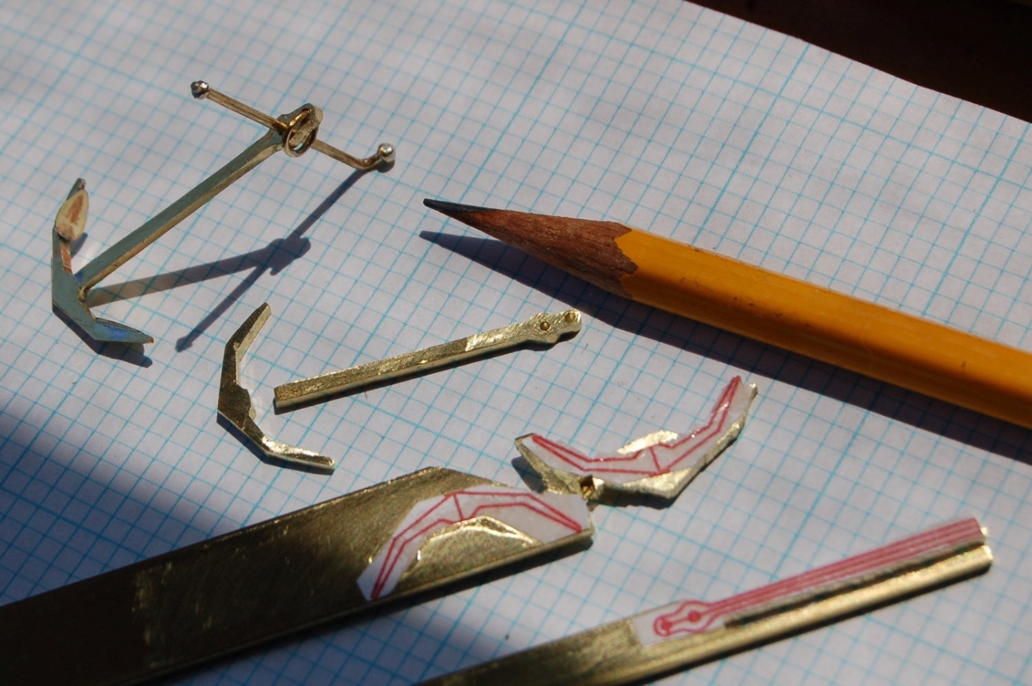
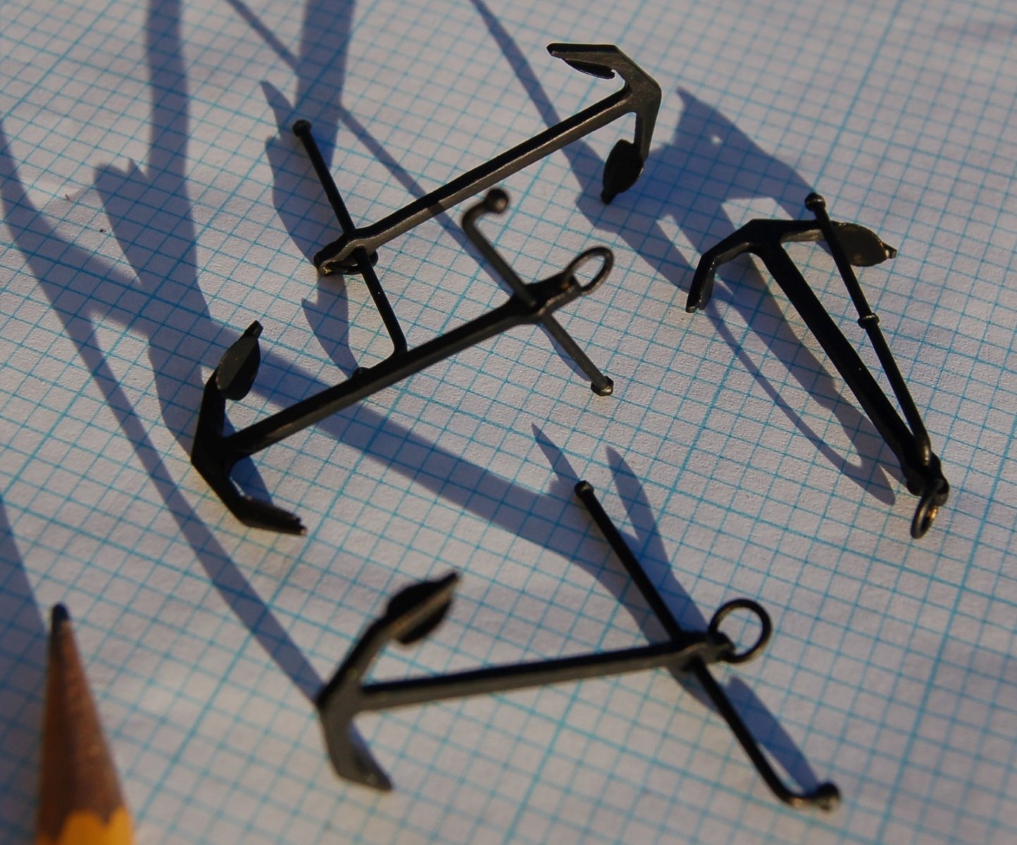
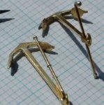
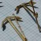
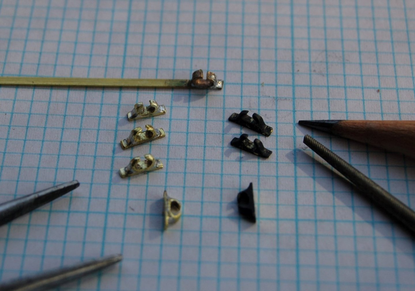
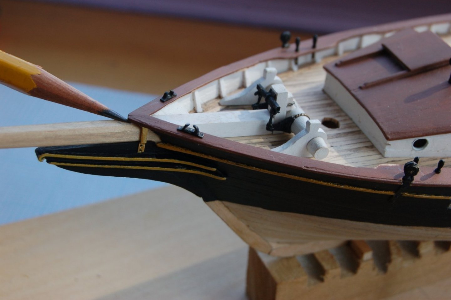
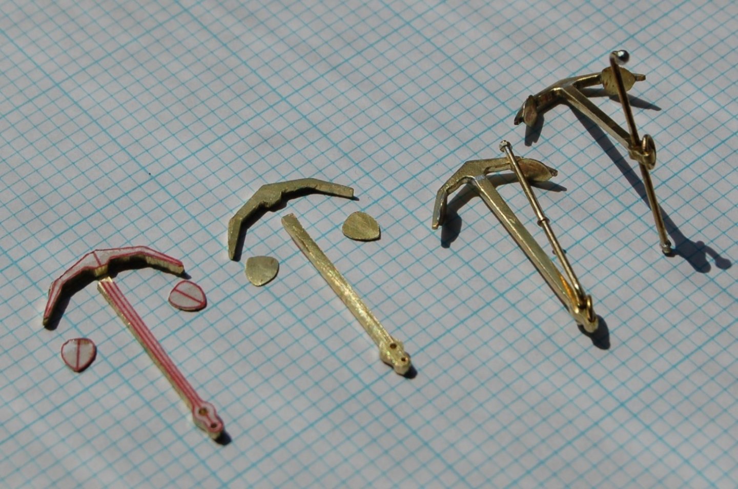
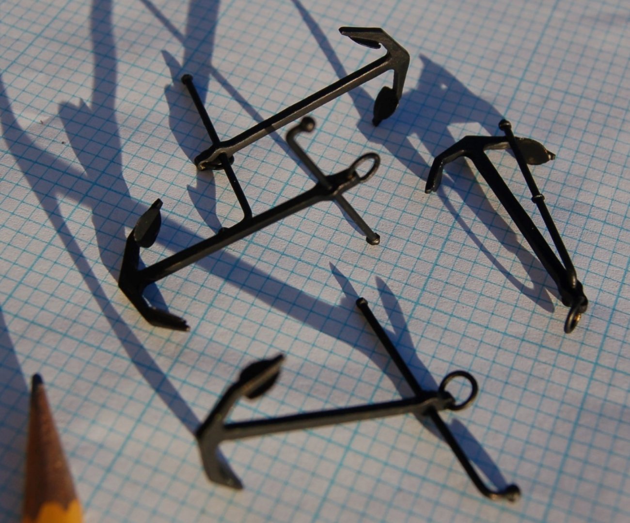
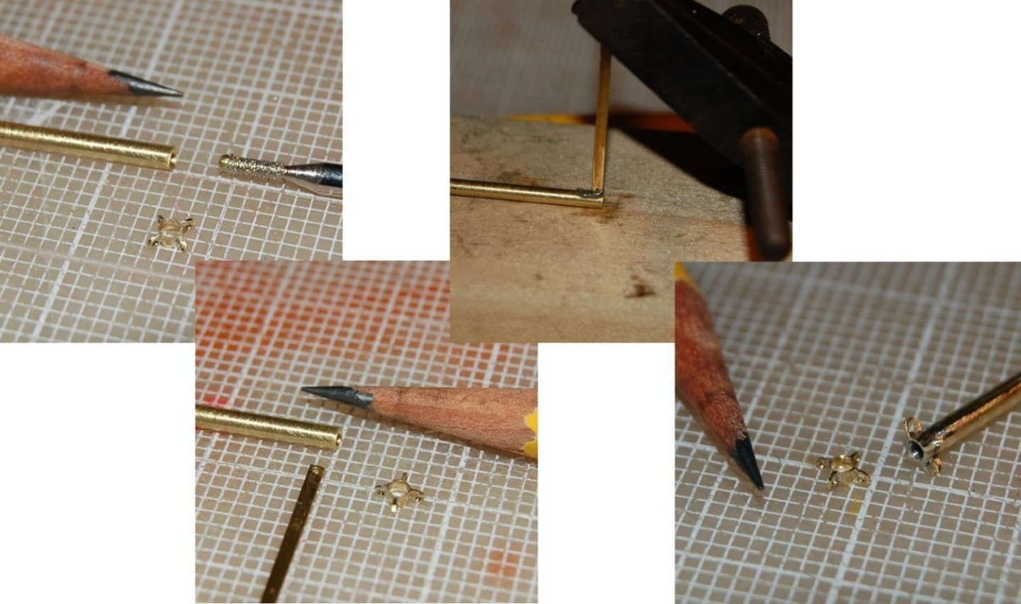
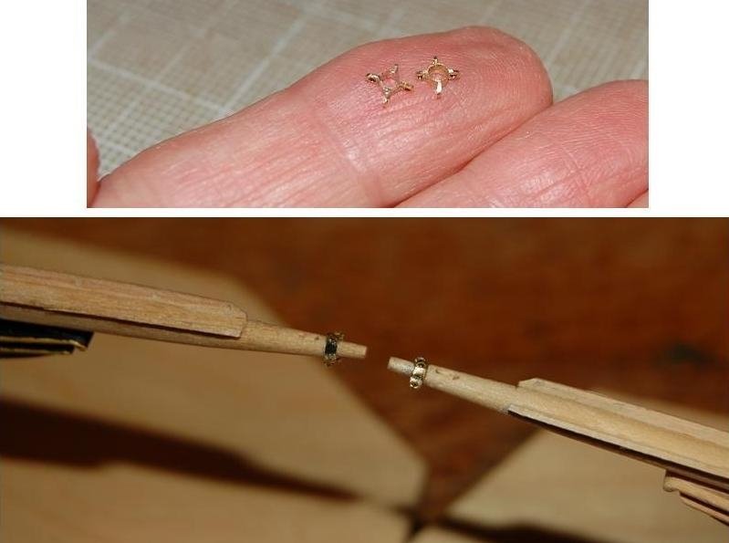
The following is a Quick report on metal work for the Dove as she sits today. As you may see, while I continue to fight with soldering technique, my product has continued to improve. Chain plates and deadeyes The chain plates are made up from 1/16” (0.060” x 0.015”) brass strips formed into a loop to receive a 0.025” brass hinge pin at one end and drilled to simulate bolt holes along the length where fixed to the hull. The chain plates are approximately ½” long. The deadeyes were turned off the end of a 1/8” birch dowel and hand drilled in the traditional three-hole pattern. Figure 16‑9 - Chain Plate Assembly Line The remaining hardware (strap and hinge pin) was formed from fine brass rod. Here are the first 6. Eight will be needed for each schooner. I think of the oversized hinge pin as representing the bolt heads on either side of a finer pin. The pin is soldered to the strap, although just as often it’s also soldered to the chainplate. Chocks (Fairleads) Figure 16‑10 - Modeling Chocks To make the eight chocks I’ll need for my two models, I form a loop of 1/16” (0.065 x 0.015”) brass strip, crush it into an elliptic form and solder it onto a similar size brass strap. Excess solder is allowed to collect between the strap and the loop forming the fillet that gives the part a more realistic shape. Then each chock is cleaned up, sculpted with fine files and painted. The black paint covers a variety of sins. The finished parts are approximately ¼” long and, I think, look pretty close to the part sitting on the railing. Figure 16‑11 - Bow Chocks, sitting in Place In this image you can also see the brass strip representing the Gammon Iron near the pencil point. Anchors Despite its fishing boat heritage, I decided the Dove would look best with iron stock anchors rather than the oversized wood stocked hooks often seen abord fishermen. Figure 16‑12 - Making up anchors from brass rod. To model Anchors, I started with the plans found in American Fishing Schooners which were redrafted in CAD and scaled to a more appropriate size for the Dove. I cut out the printed images and glued them to brass stock to guide the shaping process. The hooks are cut from ½” Brass stock 1/16” thick, while the shanks are made from ¼” x 1/16” stock. The flukes were cut from 0.015” sheet sock while the iron stock was fashioned from 0.045” diameter brass rod and the ring from 0.032” rod. The major parts were rough cut from the stock using a handheld jig saw and a rotary tool with a grit cut off wheel (goggles definitely being a good idea). The rough parts were hand finished with a variety of mini files and abrasive cloth. I soldered the parts together using positioning jigs and low temperature electronics solder. Various loops of fine brass wire were added to the stock to simulate the ball on the crooked end, the mid stock flange and the nut on the straight end. Again, I used small files to clean up the work and give some shape to the various elements. Figure 16‑13 - Anchor Parts and Assembly Options While the low temperature solder is not especially strong, I believe it will be strong enough to withstand any storm into which these hooks will be dropped. I painted the finished anchors black, noting as I did that the dark color did in fact cause them to look slenderer than the unpainted brass. Figure 16‑14 - Painted Anchors Iron Wyes At the tip of the bowsprit is an iron fitting to which the various stays and guys that come together there are attached. The fitting takes the form of an iron ring to which four eyes are welded. The piece would be pretty tiny but also prominent and it felt like it would make a fun modeling project. Figure 16‑15 - Step by Step Modeling a Wye I started this mini project with a piece of 0.095” diameter brass tubing. Fine as the tube walls were they still seemed too thick and didn’t in any case fit over the ends of the sprit. I used a fine diamond bit in a rotary hobby tool to ream out the inside diameter. The ear like eyes attached top and bottom and to both sides were formed from my favorite 0.065” x 0.016” brass strip. I drilled a fine hole in the strip then one quadrant at a time soldered the end of the strip. Typically, the solder filled my little hole but drilling the solder out of the brass was easier than drilling the brass would have been. Each tab was cut of to the desired length and shaped with fine files. The biggest trick was working quickly enough to not melt off one tab while attaching the next. Figure 16‑16 - Wyes Finished and In Place In the end this is a tiny project that many will not notice but I get a lot of satisfaction when its installed and looks fairly close to right. Hopefully it won't be so long before I have more to post. Regards Jim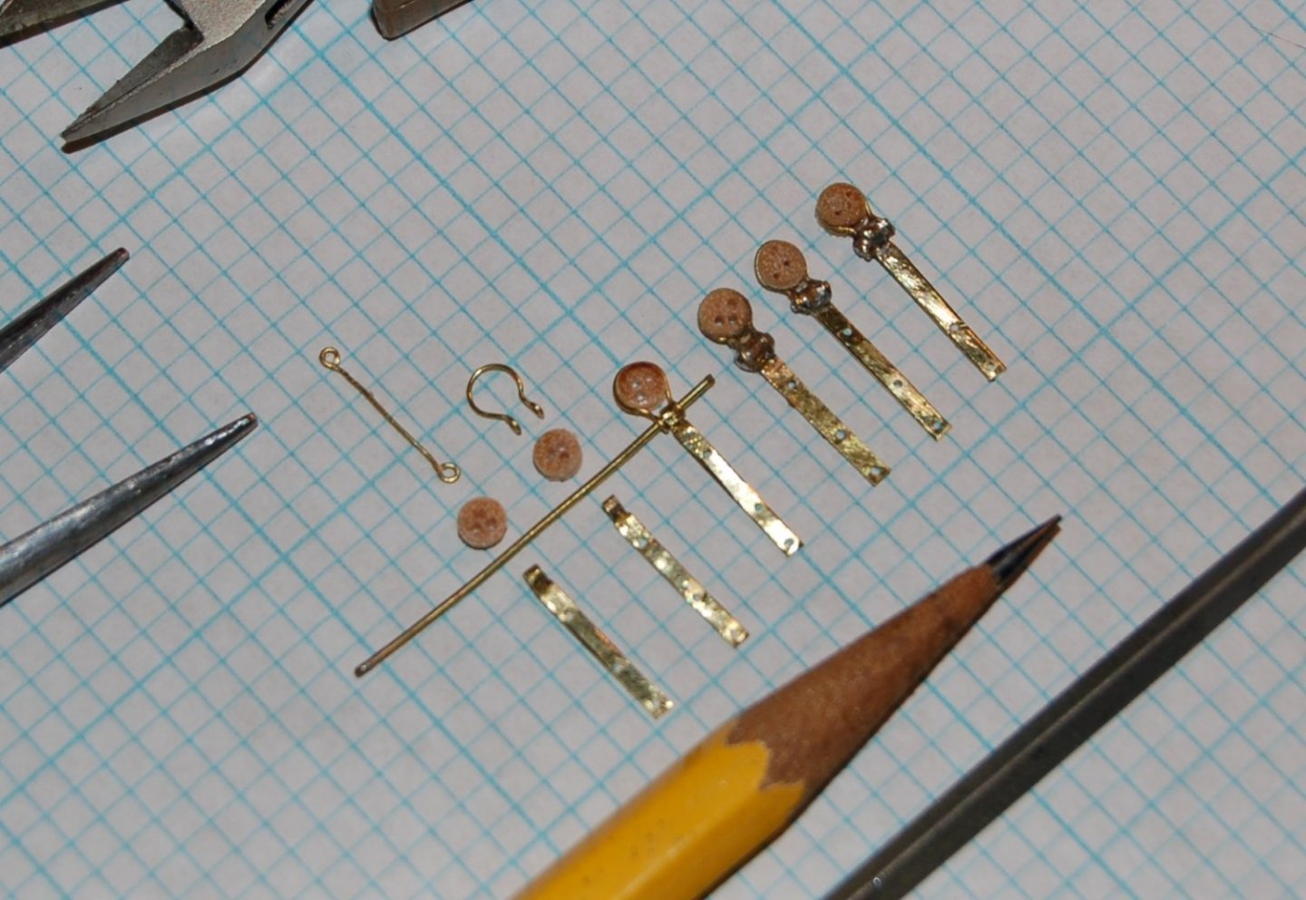
-
You might try a search on spile. There are a number of pretty good discussions on the process around. Short answer, Both top and bottom sides will likely be tapered and curved (spiled) to get a good fit.
-
A wonderful clean looking start. I look forward to seeing your next steps. Jim
-
Well done, a clean build and an interesting variation on forming the hull. Very nice all the way around. Taking your time is certainly paying off. Jim