tlevine
-
Posts
1,932 -
Joined
-
Last visited
Content Type
Profiles
Forums
Gallery
Events
Everything posted by tlevine
-

NRG Rigging Project by tlevine
tlevine replied to tlevine's topic in - Kit build logs for subjects built from 1751 - 1800
Thanks, Tom. Sorry for the delayed response but I was on the road and without internet access. -
NRG Rigging Project by tlevine
tlevine replied to tlevine's topic in - Kit build logs for subjects built from 1751 - 1800
At this point videos are not planned. There is more detail in the monograph and, if you purchase the kit, I would be available for questions. The Guild hopes to have it available in 4-6 weeks.- 30 replies
-
- 8
-

-
- rigging/masts
- NRG
- (and 1 more)
-
HMS EURYALUS by Matiz - FINISHED - scale 1:56
tlevine replied to matiz's topic in - Build logs for subjects built 1801 - 1850
Congratulations on finishing this masterpiece. Looking forward to your next project. -
NRG Rigging Project by tlevine
tlevine replied to tlevine's topic in - Kit build logs for subjects built from 1751 - 1800
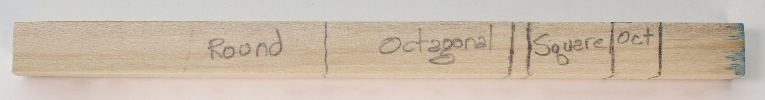
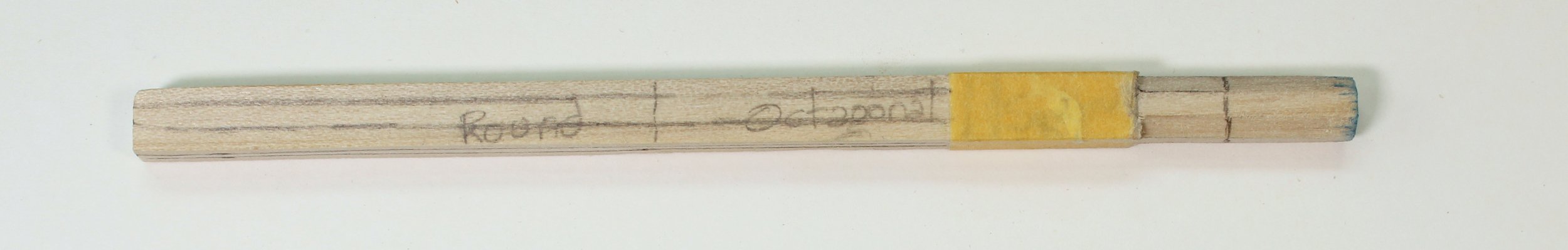
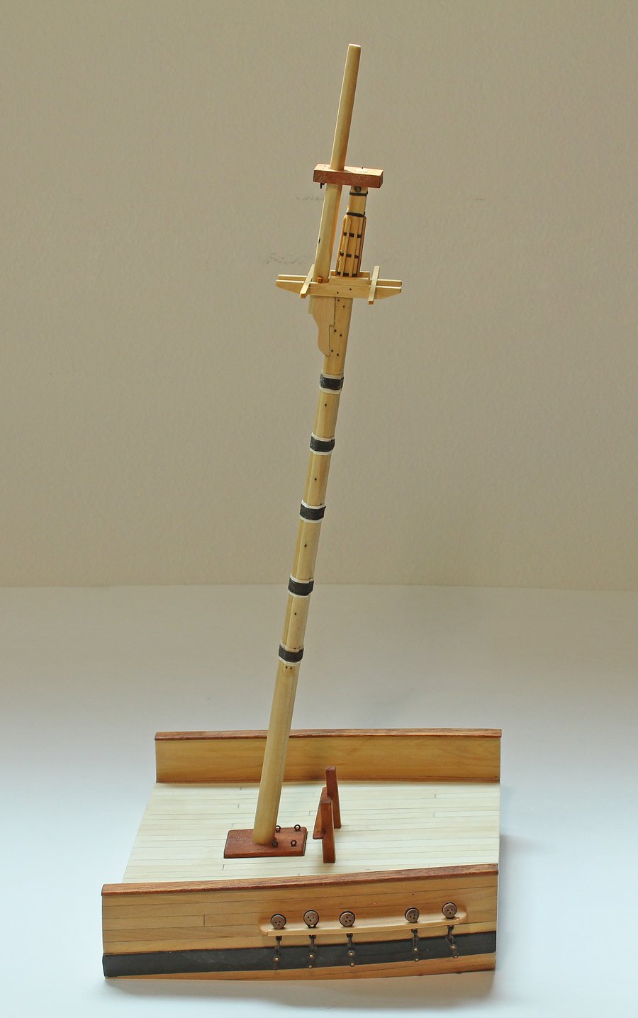
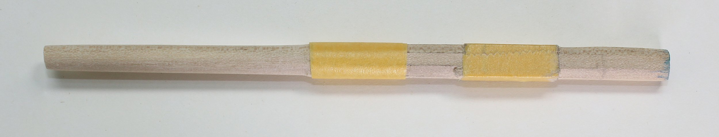
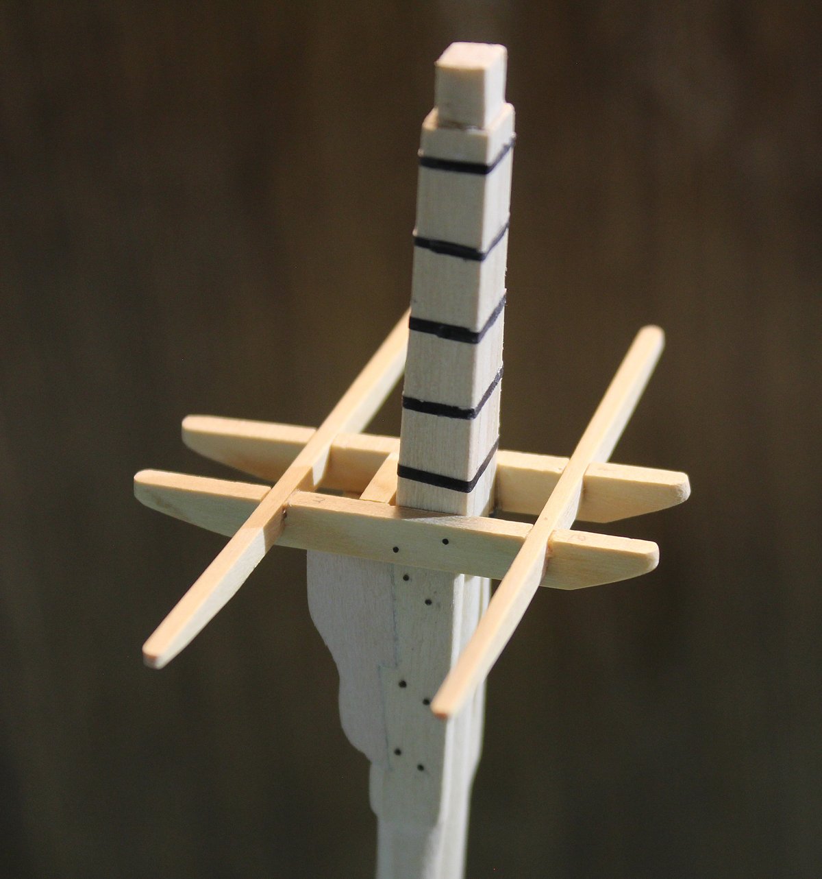
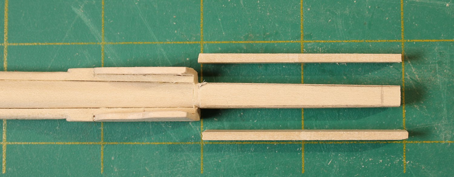
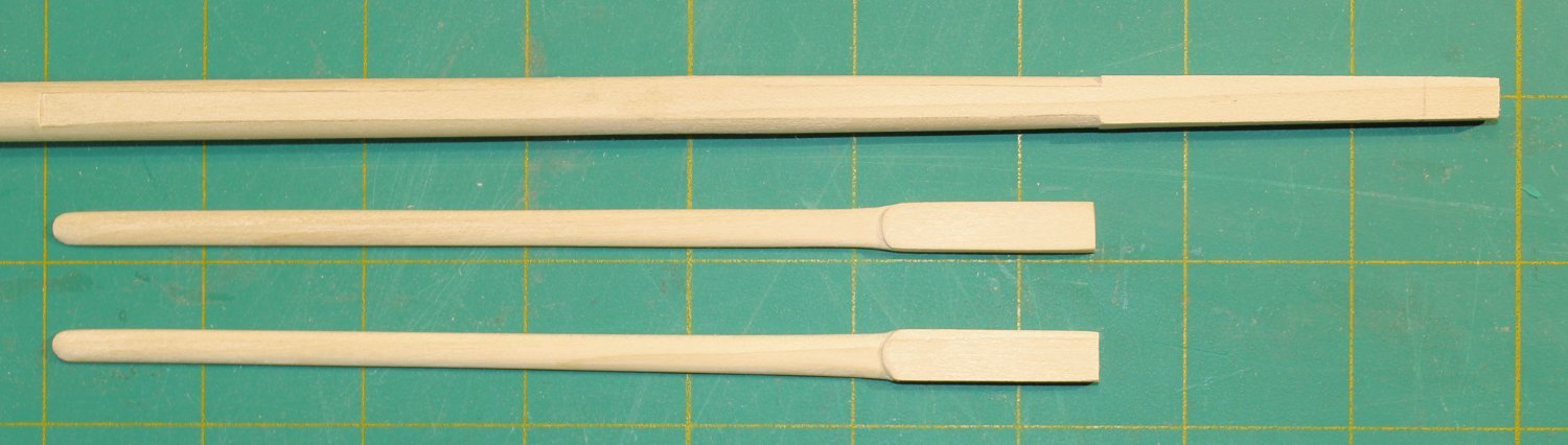
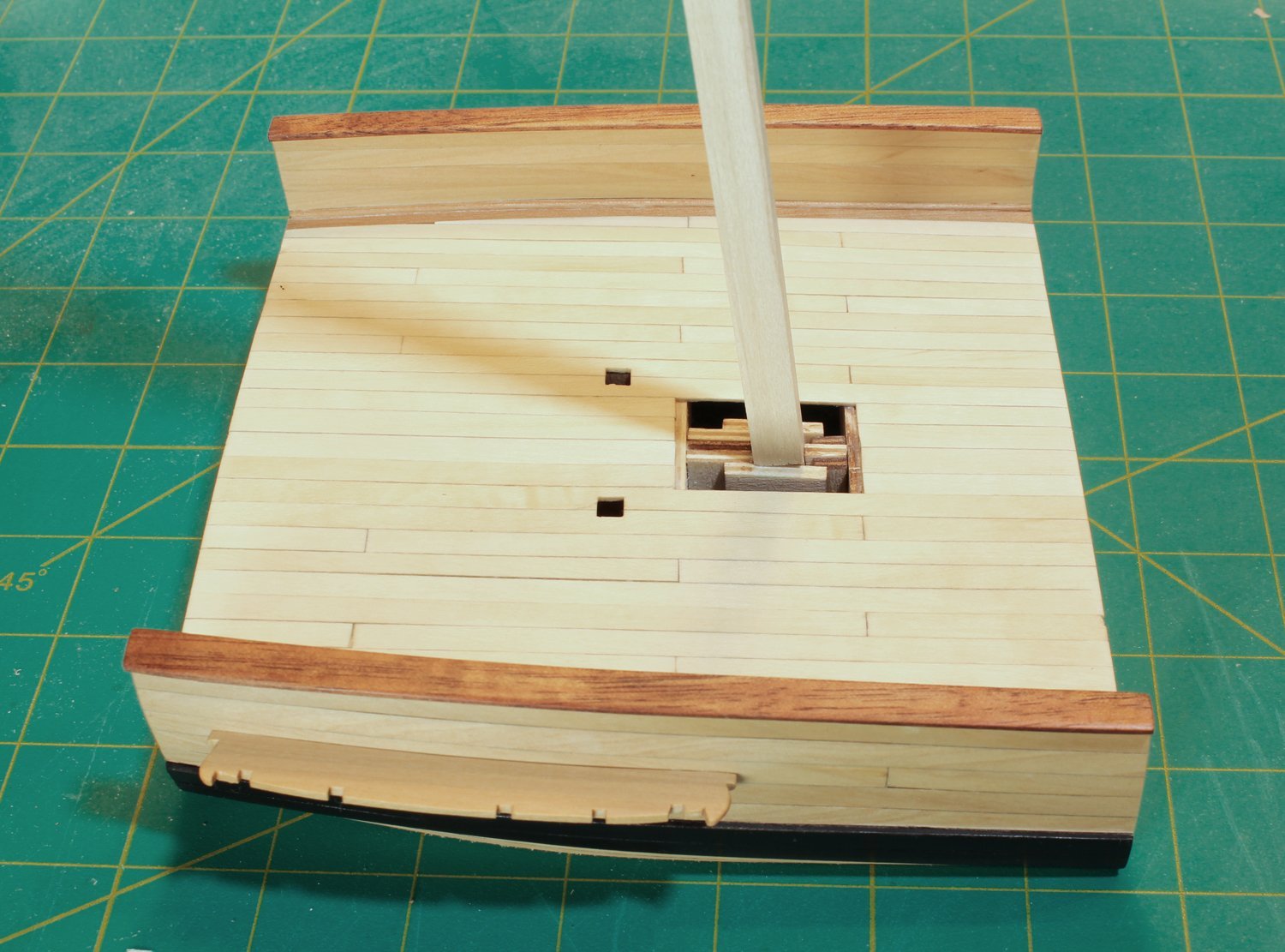
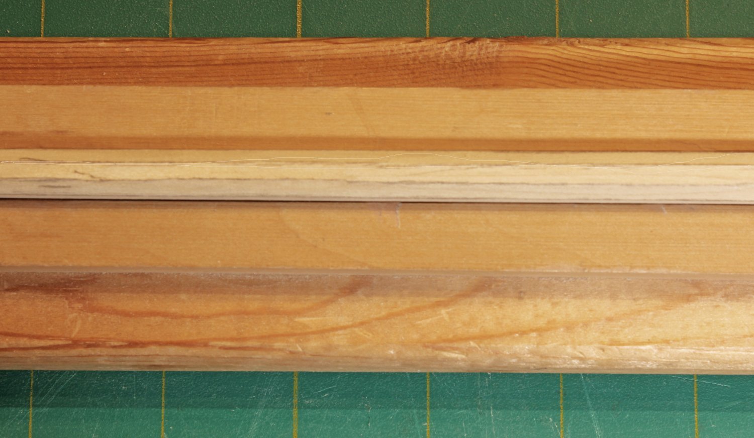
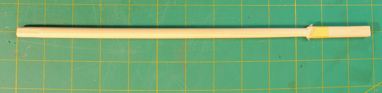
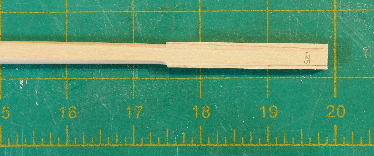
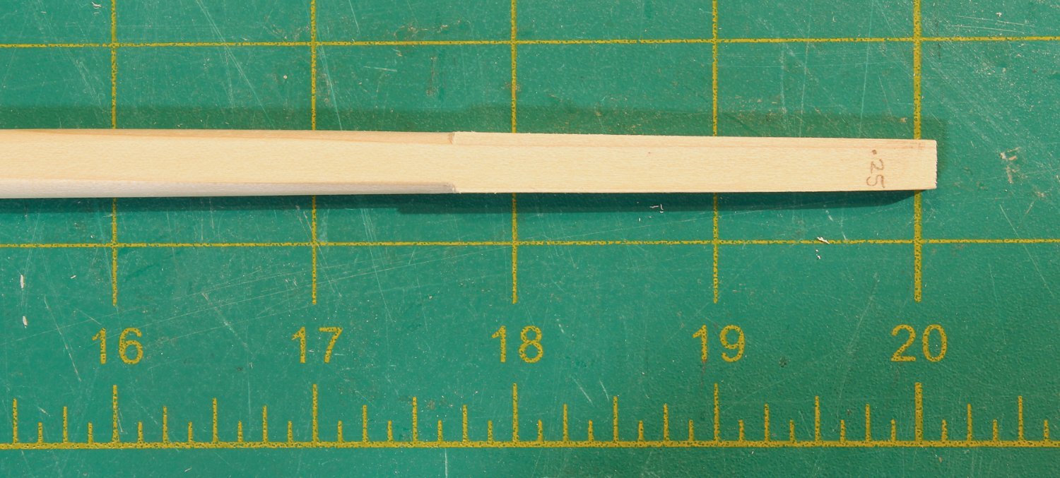
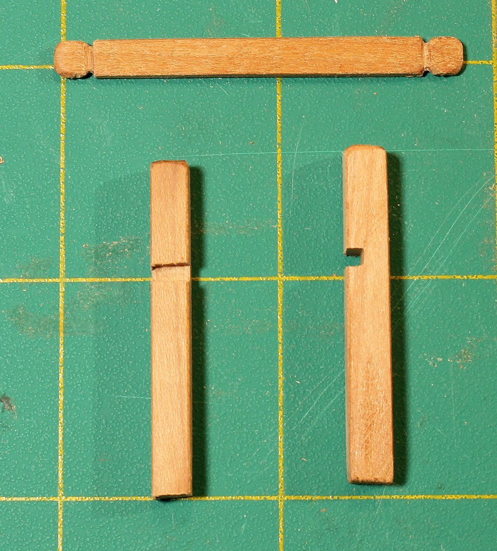
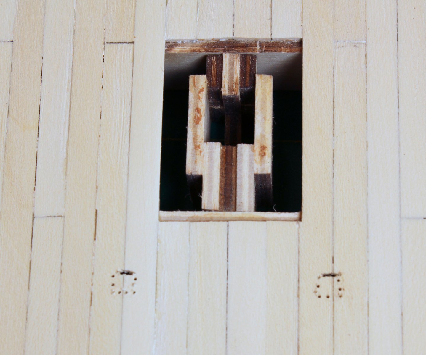
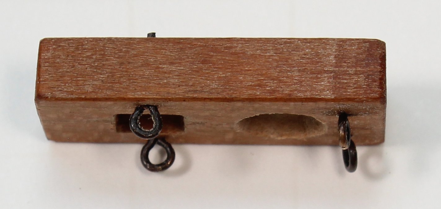
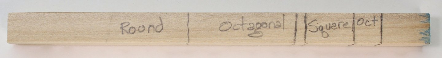
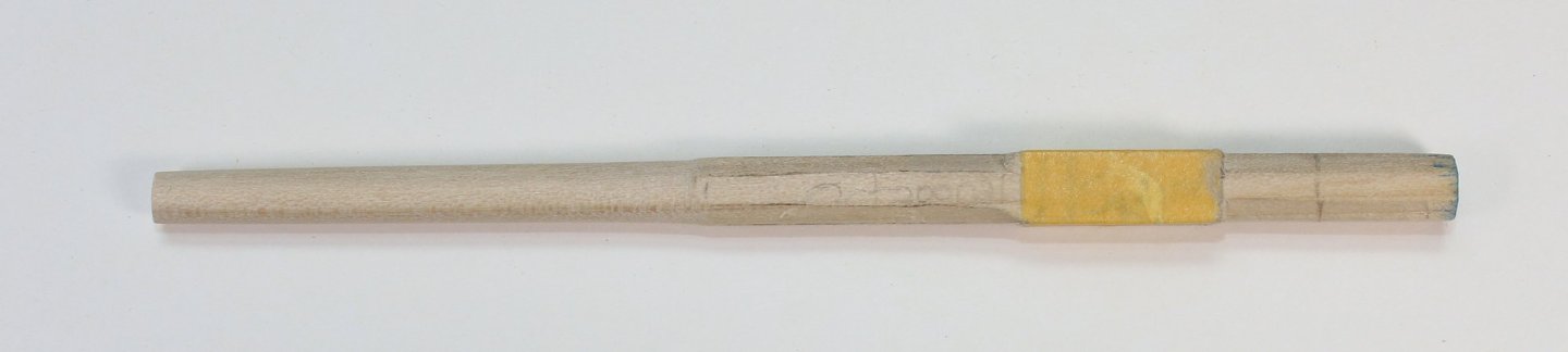
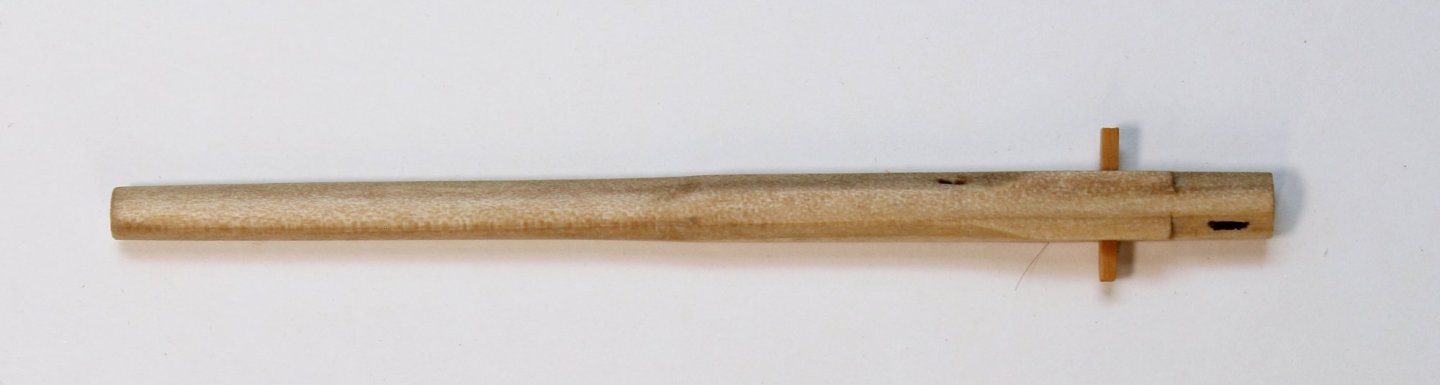
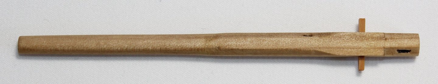
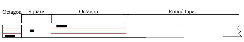
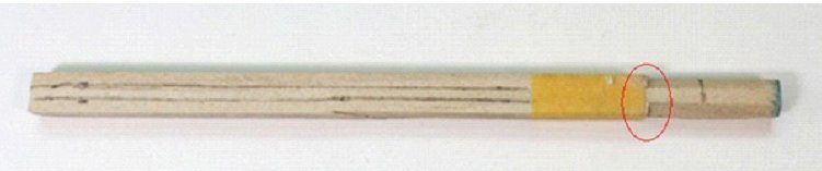
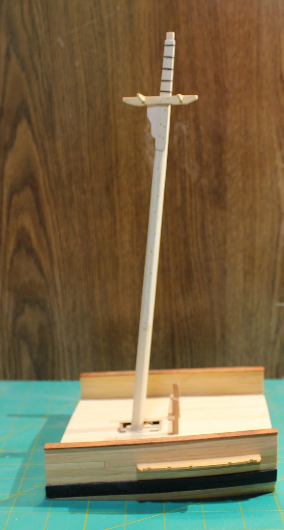
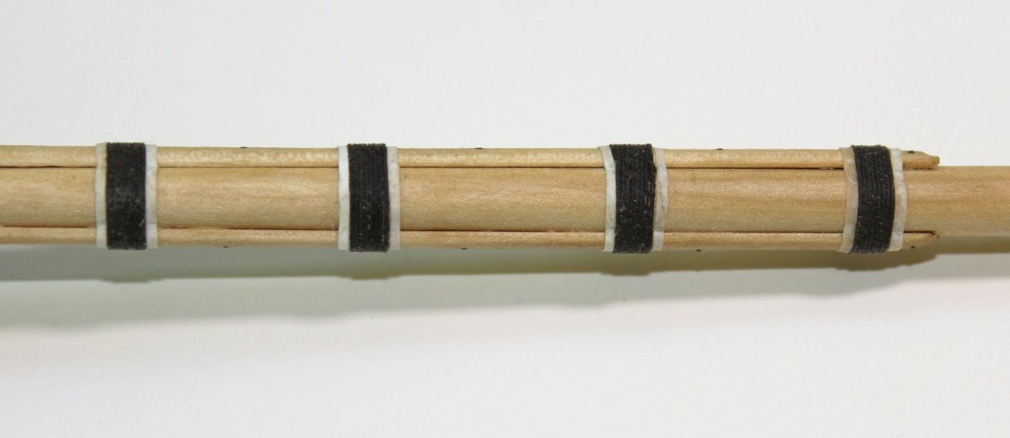
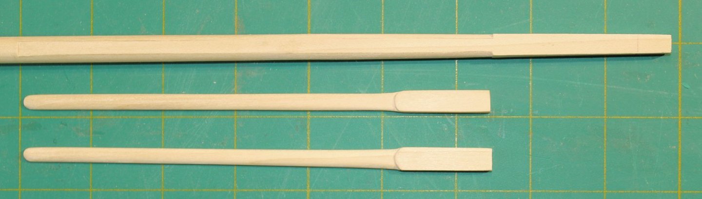
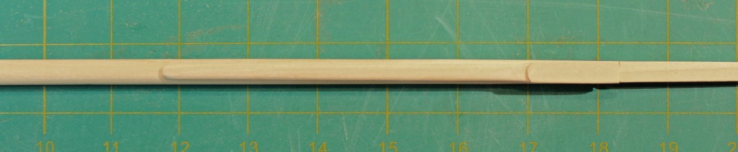
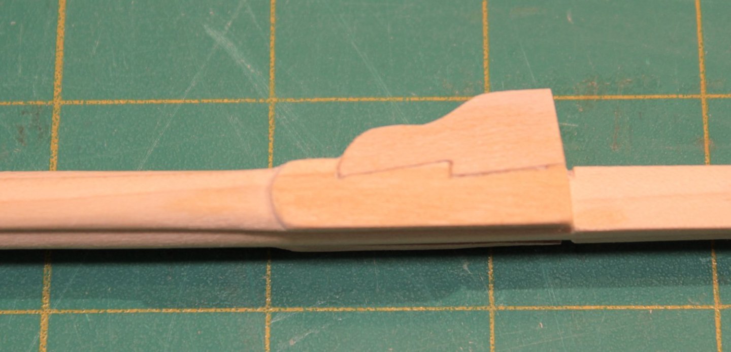
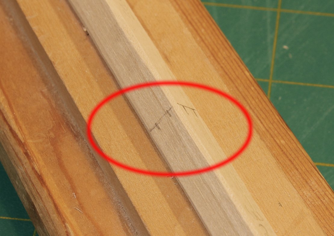
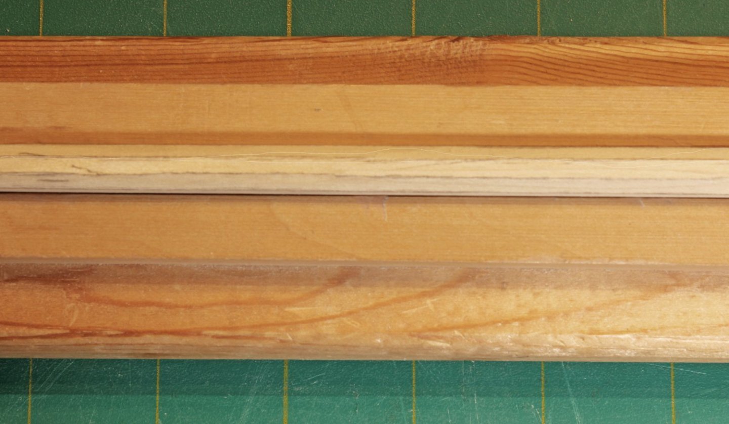
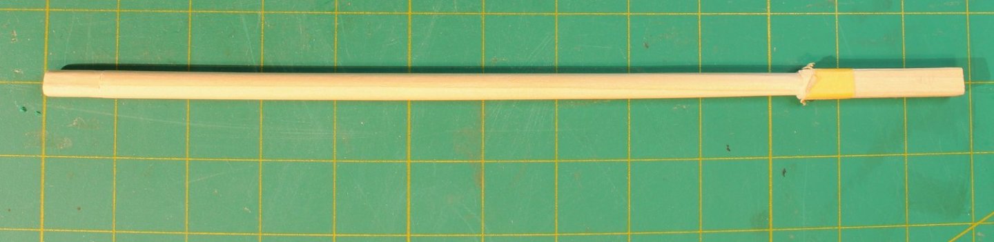
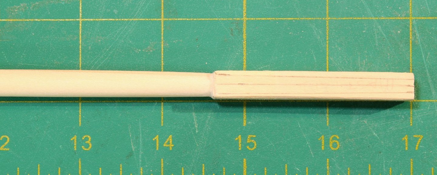
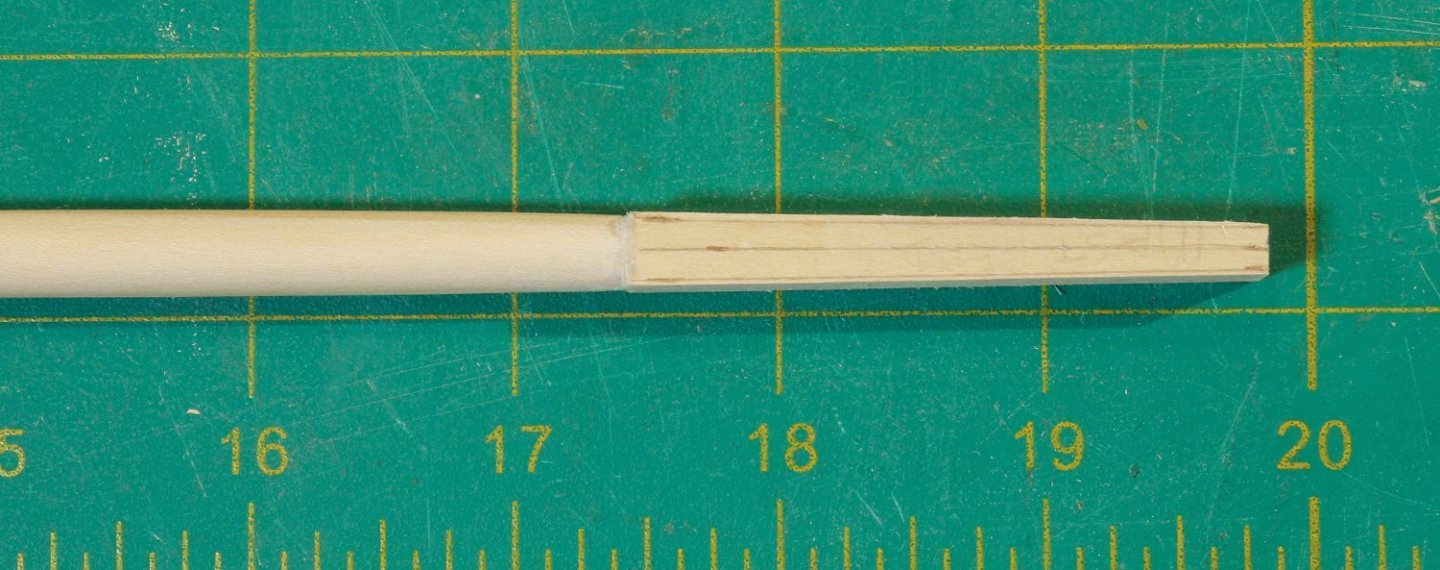
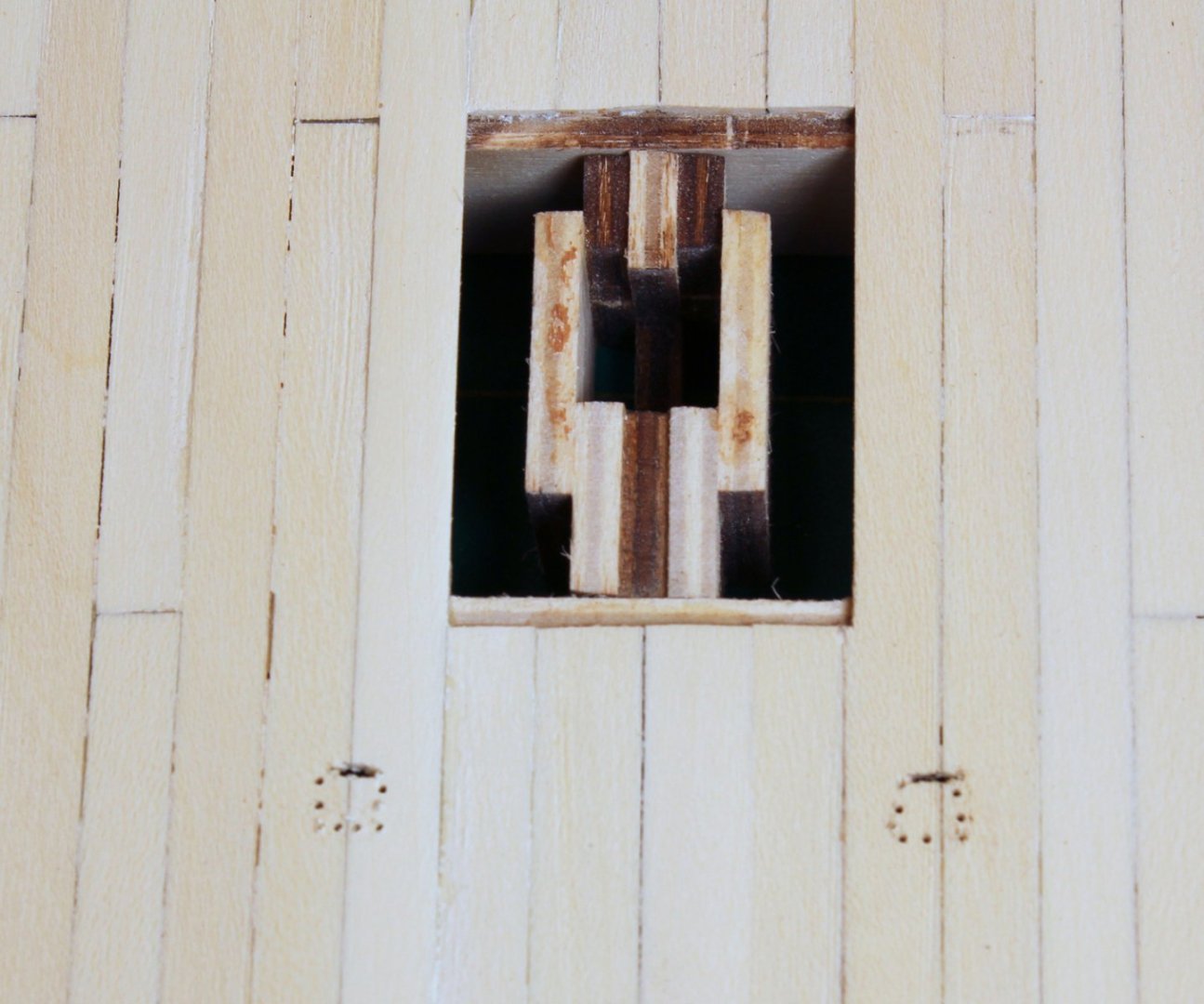
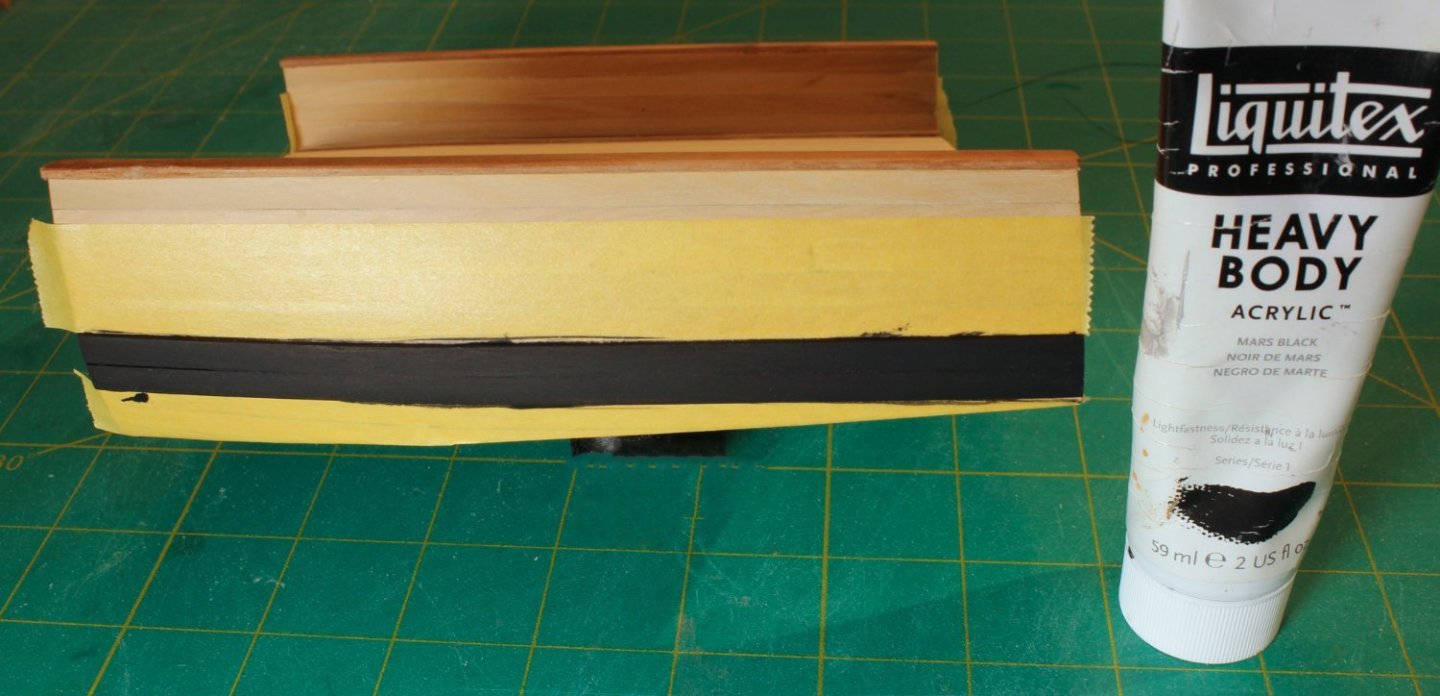
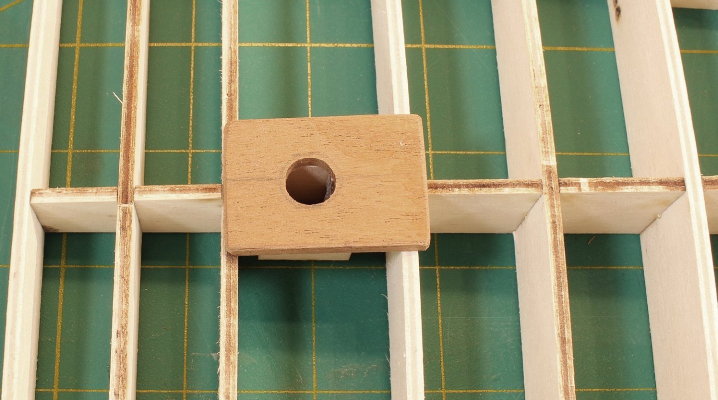
The mast cap has two openings: a round one for the topmast and a square one for the lower mast head. There are four eyebolts that extend all the way through the mast cap. I raided my scrap box for a contrasting color piece of wood. Both openings were made with a regular drill. The square opening was then shaped with a chisel and the round one was enlarged with sandpaper wrapped around a dowel. It will not be installed until much later. Although it also will not be installed for a while, I made the topmast next. The dimensions of the topmast are determined by the diameter of the lower mast. The lower end of topmast is 7/10 the diameter of the mast and the upper end is 11/20. This will be a stub topmast as the actual length of this mast would be 8” on the model. Its shape is more complicated than the lower mast. The lowest section (the block) is octagonal, the next section is (the heel) square, followed by another octagonal section. The upper part of the topmast is round, tapering as it goes to the head. There are three openings in the mast; the middle one is for the fid (the rectangular peg which prevents the mast from falling between the trestle trees) and the other two are for sheaves. The kit will contain a template for the topmast. Starting with a ¼” square dowel, I marked out the mast for the various transition points. Using the 7:10:7 ratio for determining the corners of the octagon, I drew the lines for those two sections. The mast taper begins at the end of the upper octagon. The blue line is the centerline and the red lines are the corners of the octagons. Just as was done for the main mast, I taped off the square section to protect it from errant chisel cuts. The pictures shows a completed topmast above a square dowel. There is extra wood on the top and bottom of the dowel for ease of handling. I used a saw to cut a shallow groove between the octagonal and square areas on the corners of the square section (circled area). This transition should stay sharp. The lower octagonal section was shaped with a sanding stick. The upper octagon and round area were both shaped as octagons, without any taper. Another piece of tape was used to protect the upper octagon and the upper part of the mast was rounded and tapered. After removing the tape, the transition between the octagonal and round sections and between the square and upper octagonal sections were smoothed. Making the holes for two sheaves and the fid was next. The upper and lower sheave openings are in the octagonal sections and are 90 degrees to each other and 45 degrees to the fid hole. The dimensions for the fid opening are one-third the mast diameter high and one-quarter the mast diameter wide, in this case 3” x 2.5”. The opening was formed from multiple drill holes, squared off with a #11 blade. The fid was made slightly smaller than the size of the opening and long enough to span the trestle trees. The sheave openings are 8” long and 1.5” wide. I simulated the sheaves on this model. These were trickier to drill accurately because they are on angled faces. Here is how I made them. The sheave opening was marked on both sides of the mast. I put the mast in a vise, clamping it in the upper octagonal area, just above the sheave opening. A small hole was drilled near the top and bottom of the sheave opening but I did not drill completely through the mast. The mast was repositioned in the vise and the holes on the other side were drilled. The holes on each side were enlarged to the correct width of the opening. I did this slowly, working a little bit on one side and then switching to the other side. The holes eventually met. Then, using a #11 blade, a shallow groove representing the sheave was formed between the two holes and the “sheave” was painted. The final step was to cut off the excess wood at the top and bottom of the topmast and apply a finish. This is how it looked installed.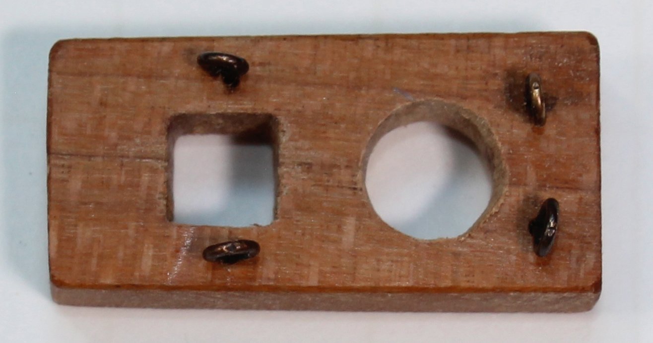


- 30 replies
-
- 22
-
-

-
- rigging/masts
- NRG
- (and 1 more)
-
Or go to the NRG store. https://thenrgstore.org/collections/the-nautical-research-journal
-
NRG Rigging Project by tlevine
tlevine replied to tlevine's topic in - Kit build logs for subjects built from 1751 - 1800
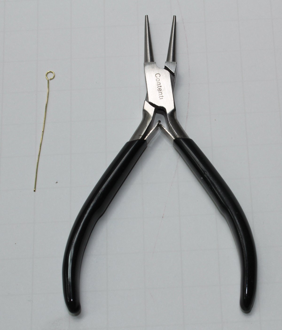
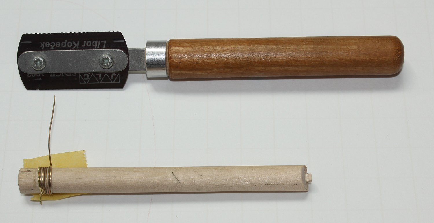
Most rings and eyebolts provided in kits are oversized, especially at the smaller scales. They are very easy to make. To make rings, temper (soften) brass or copper wire of the appropriate gauge by heating it in a flame. I use my gas cooktop. Let it cool slowly. Drill a hole larger than the wire in one end of a dowel that is slightly larger than the desired inside diameter of the ring. Thread the wire through the hole and tightly wrap the wire around the dowel. When you are finished, tape one side of the wire. This will help prevent the rings from flying away when you cut them from the dowel. Use a metal cutting saw to cut through the wire. If you don’t own the Czech-made JLC saw, get one. They are fantastic. No monetary interest in the company, so here is the link to their website. https://www.umm-usa.com/catalog/tools_JLC.html The pirated cheap imitations on Amazon are not the same quality. Gently bend the wire to close the gap left by the saw kerf. Clean and blacken. Easy! For rings that are going to be under a lot of tension, solder the ring closed before blackening. If you are making a lot of rings, you can chuck the dowel into a drill rather than hand wrapping it. Eyebolts are just as easy to make but you will need fine-tipped round-nosed pliers. Your best source for this tool is a jewelry supply store. Mark on your pliers the desired inner diameter of the eyebolt. Take a length of wire and file the end flat with a metal file. Grasp the wire between the jaws of the pliers without any wire protruding beyond the jaws and wrap it around one of the jaws until you have a complete loop. Sharply bend the wire back towards you to form the stem. Cut to length, clean, blacken and repeat.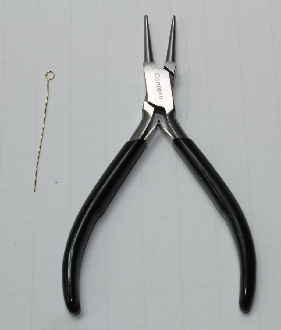

- 30 replies
-
- 11
-
-
- rigging/masts
- NRG
- (and 1 more)
-
NRG Rigging Project by tlevine
tlevine replied to tlevine's topic in - Kit build logs for subjects built from 1751 - 1800
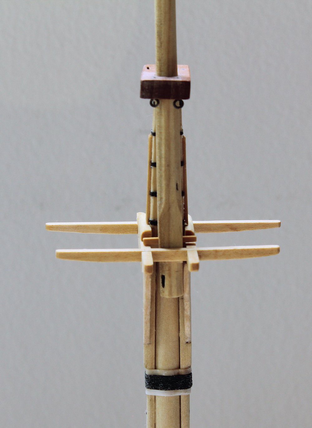
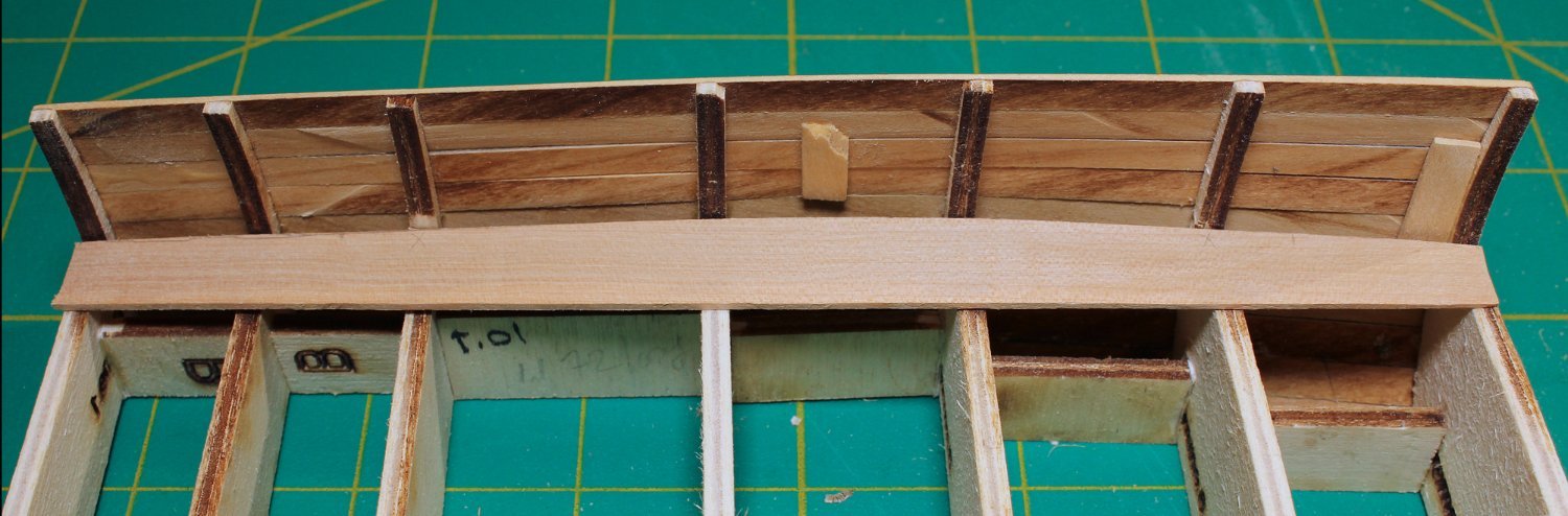
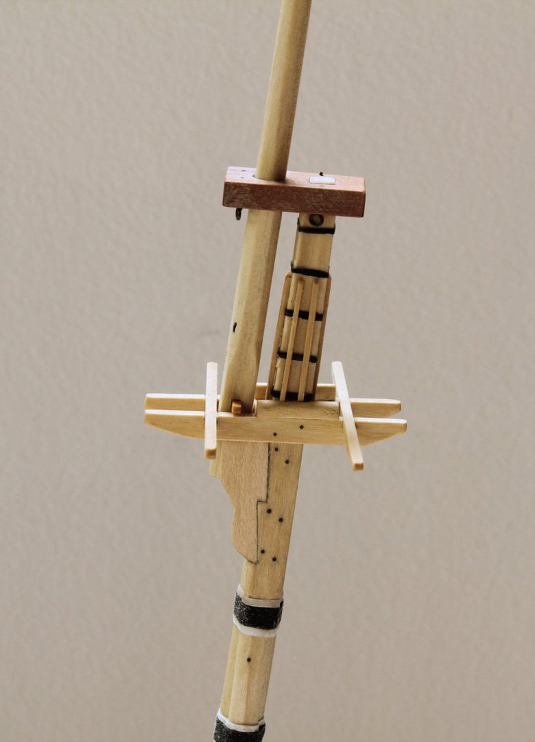
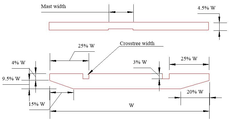
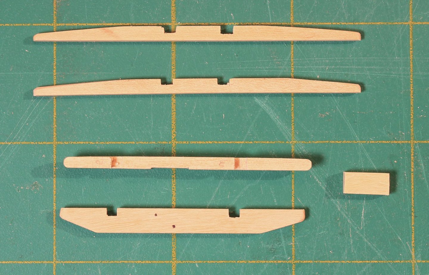
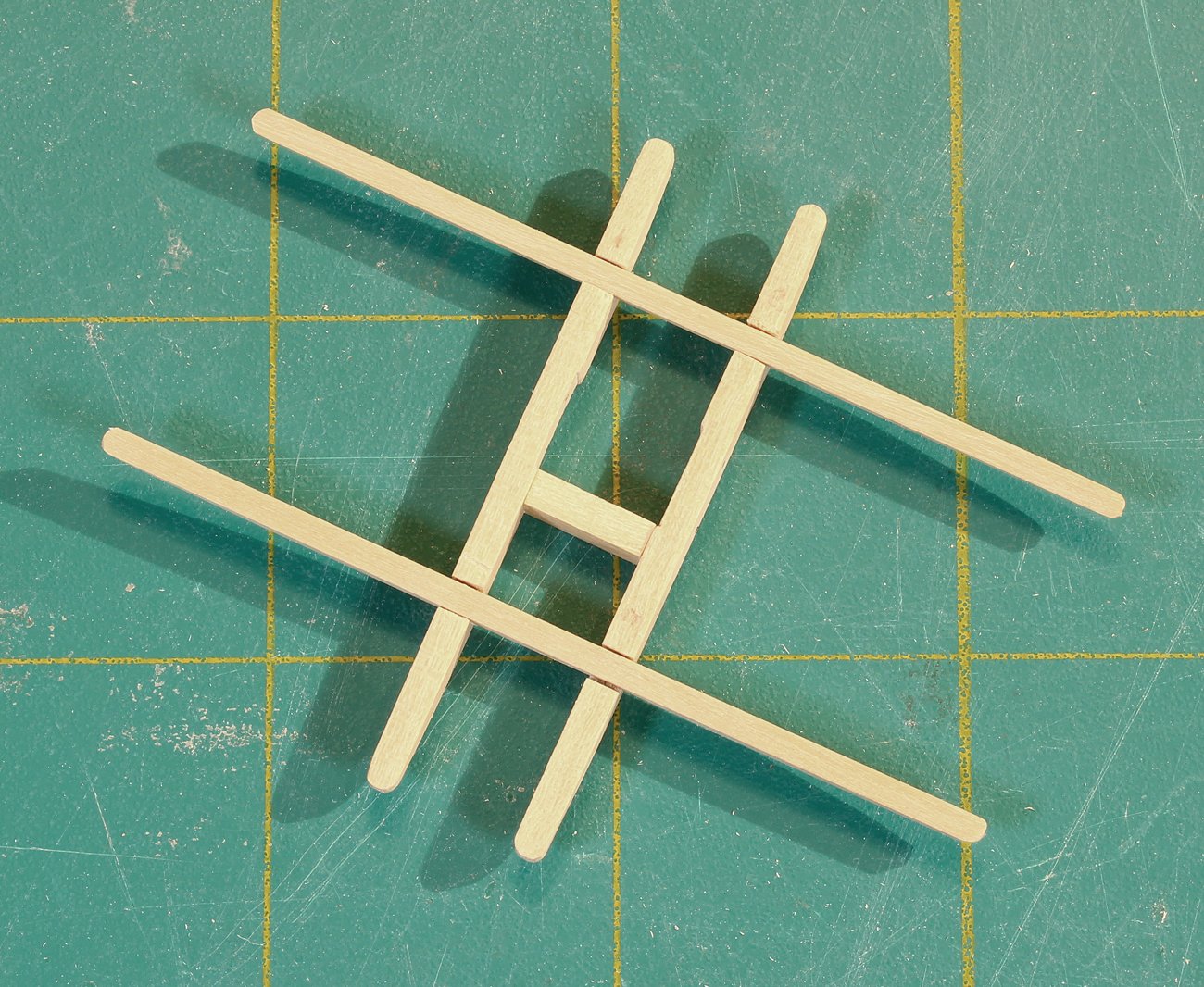
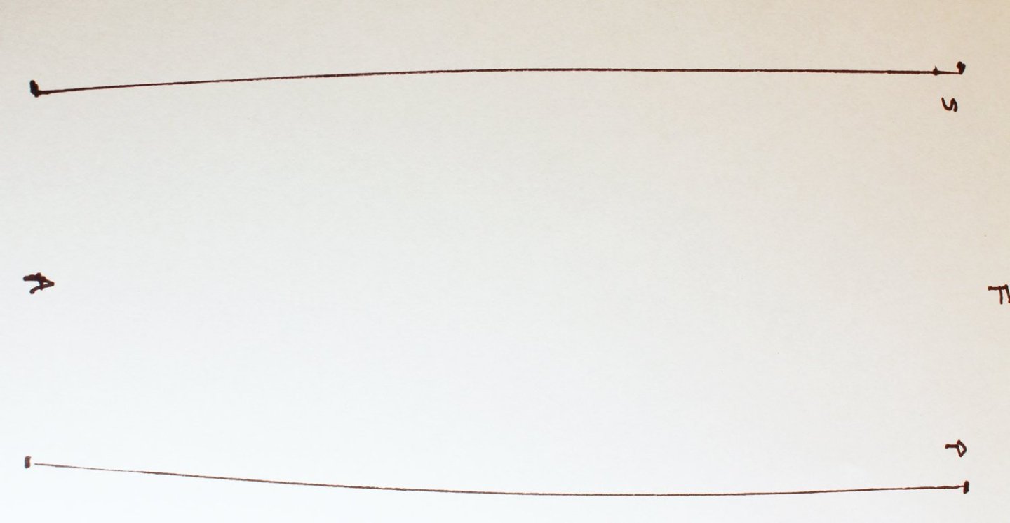
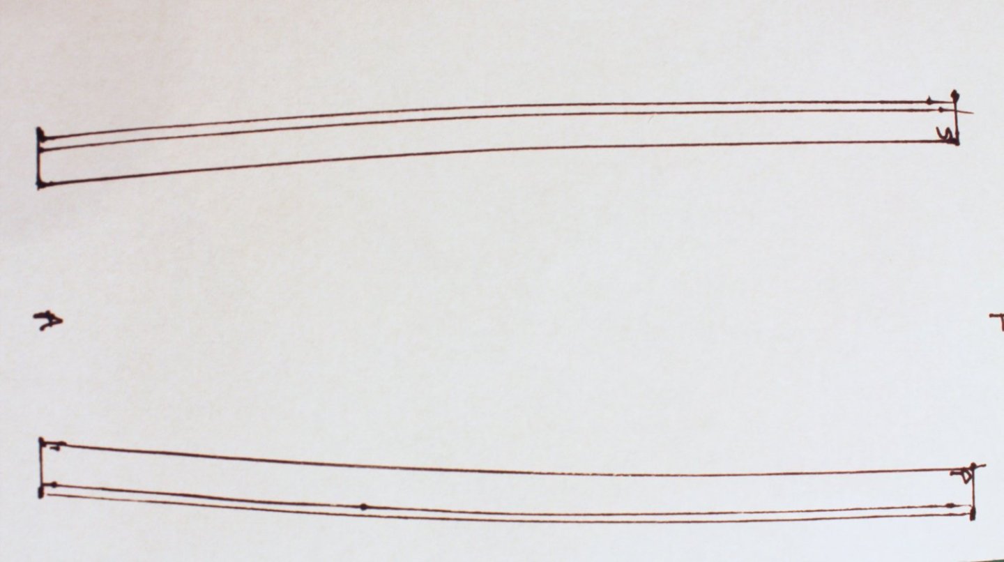
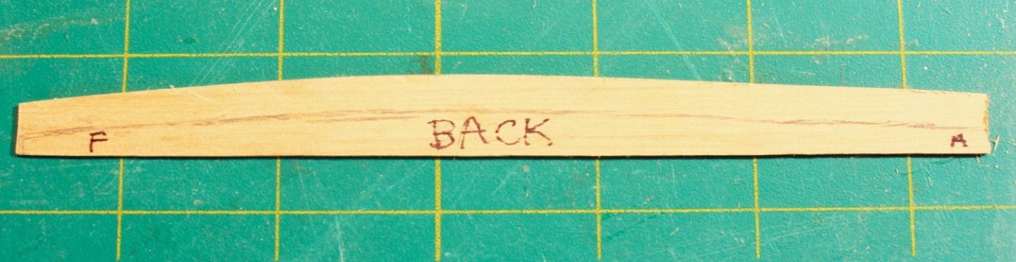
The dimensions of the top are determined by the size of the topmast; the dimensions of the trestle and cross trees are derived from the size of the top. The topmast on this ship was specified on the plans as 32’ 10”. The width of the top is 1/3 the length of the topmast wide and ¾ the top’s width fore-to-aft. The hole in the top is 5/12 the width of the top. The kit will provide a template for the top. The trestle trees run fore and aft; the cross trees run across the ship. The trestle trees are as long as the top. The cross trees are different lengths; the fore cross tree is shorter than the aft one because of the curvature of the top. Look at the following drawings. The dimensions of the trestle and cross trees are derived from the width of the top (W). There is a small notch on the inside face of the trestle tree for the mast head. I made them from 1/8” basswood sheet and sanded them down to the correct thickness. It is important to make sure that the top surface of the assembly is not twisted. The easiest way to avoid twisting is to turn it upside down and put a weight on top of it while the glue dries. Trestle Tree The small piece of wood between the cross trees is called the chock. It is a spacer between the mast head and the topmast. It is the same height and width as the trestle tree. I inserted the mast into the hole in the deck. As mentioned previously, the trestle trees are horizontal to the water line. The cross/trestle tree assembly was placed onto the bibs and the angle of the top of the bibs was adjusted with a sanding stick until the trestle trees were horizontal. They were glued to the bibs. The final pieces to install onto the trestle tree are the bolsters. These are quarter-round pieces of wood that prevent the shrouds from rubbing against the trestle trees. They are slightly wider than the trestle tree and one-third its height. Because the shrouds extend aft from the mast, the bolster starts at the fore end of the mast head and extends back to the aft cross tree. I have added bolts to the trestle trees using 24 g copper wire. Just as the bolsters protect the trestle trees, battens protect the mast head. There are two battens on each side of the masthead and end below the second hoop from the top. In order to lay flat against the mast head, small grooves were cut into the undersurface of each batten where it crossed a hoop with a #11 blade.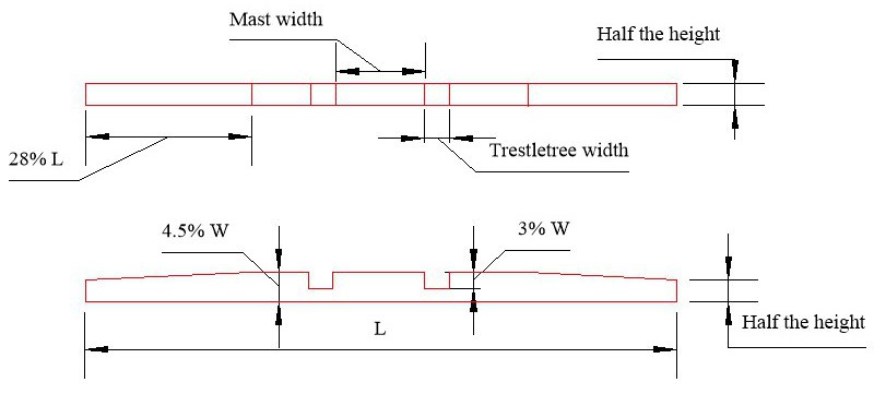

- 30 replies
-
- 18
-
-
-
- rigging/masts
- NRG
- (and 1 more)
-
Use of “other power tools”
tlevine replied to kgstakes's topic in Modeling tools and Workshop Equipment
I used a Cricut once to attempt to cut planks from 1/16" boxwood. There was not need for a second attempt. It worked fine on basswood. -
NRG Rigging Project by tlevine
tlevine replied to tlevine's topic in - Kit build logs for subjects built from 1751 - 1800
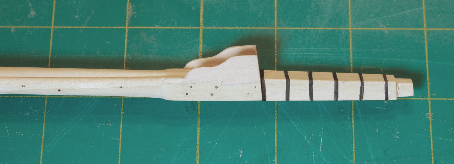
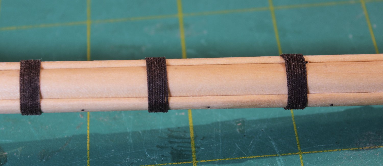
Time to build up the port and starboard sides of the mast head. I used the mast template to determine the dimensions. A real mast would have its top cut at an angle to lock it into the mast cap. This detail is not visible so I shaped it as a simple square. The full- sized dimensions are 9” square by 11”tall, which is the thickness of the mast cap. Iron bands were placed around the mast head at regular intervals. I used paper dyed with archival ink. On this photo you can see that I have added bolts to the cheek. The bolts are made from 24 g copper wire patinated with liver of sulfur. The wooldings provide extra strength to the mast. The number and composition varied based on the era. At this time, they were made of 2.5” tarred rope (all rope dimensions are circumference). Because I will be using several diameters of line in the build, I made a table consisting of the full-sized circumference, the circumference at 1:48 scale and the diameter at 1:48 scale. The easiest way to determine the diameter of your rope is to wrap 10-20 windings around a dowel, measure the distance and divide it by the number of windings. Remember, circumference is πd so the rope diameter is circumference/π. I used eight wraps for each woolding. To hide the ends of the wooldings, I tucked them in the gap between the mast and the cheeks. Above and below the wooldings are wooden hoops. I simulated them by cutting strips of paper and wrapping two layers around the mast. This gave the hoops the appropriate thickness.

- 30 replies
-
- 24
-
-
- rigging/masts
- NRG
- (and 1 more)
-
NRG Rigging Project by tlevine
tlevine replied to tlevine's topic in - Kit build logs for subjects built from 1751 - 1800
Thanks. I forgot to mention that.- 30 replies
-
- 6
-
-
- rigging/masts
- NRG
- (and 1 more)
-
NRG Rigging Project by tlevine
tlevine replied to tlevine's topic in - Kit build logs for subjects built from 1751 - 1800
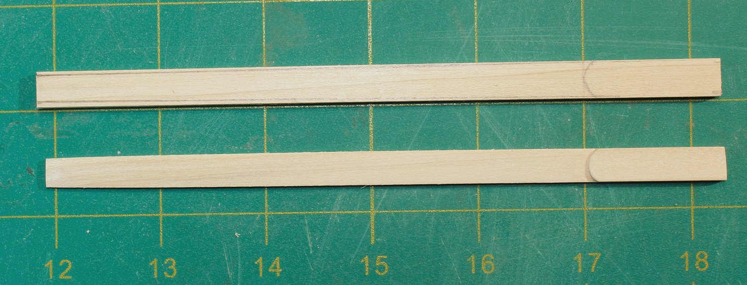
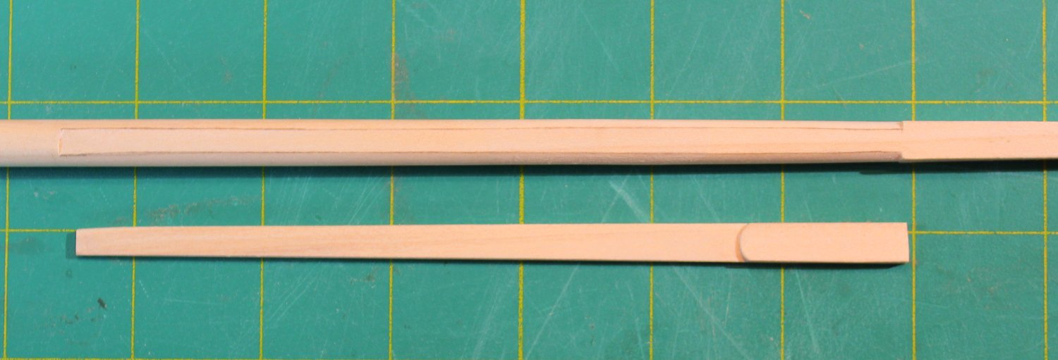
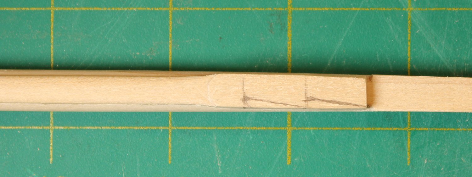
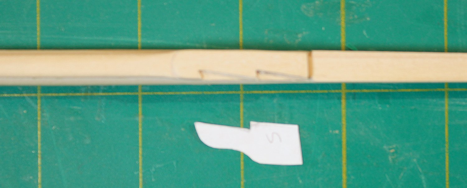
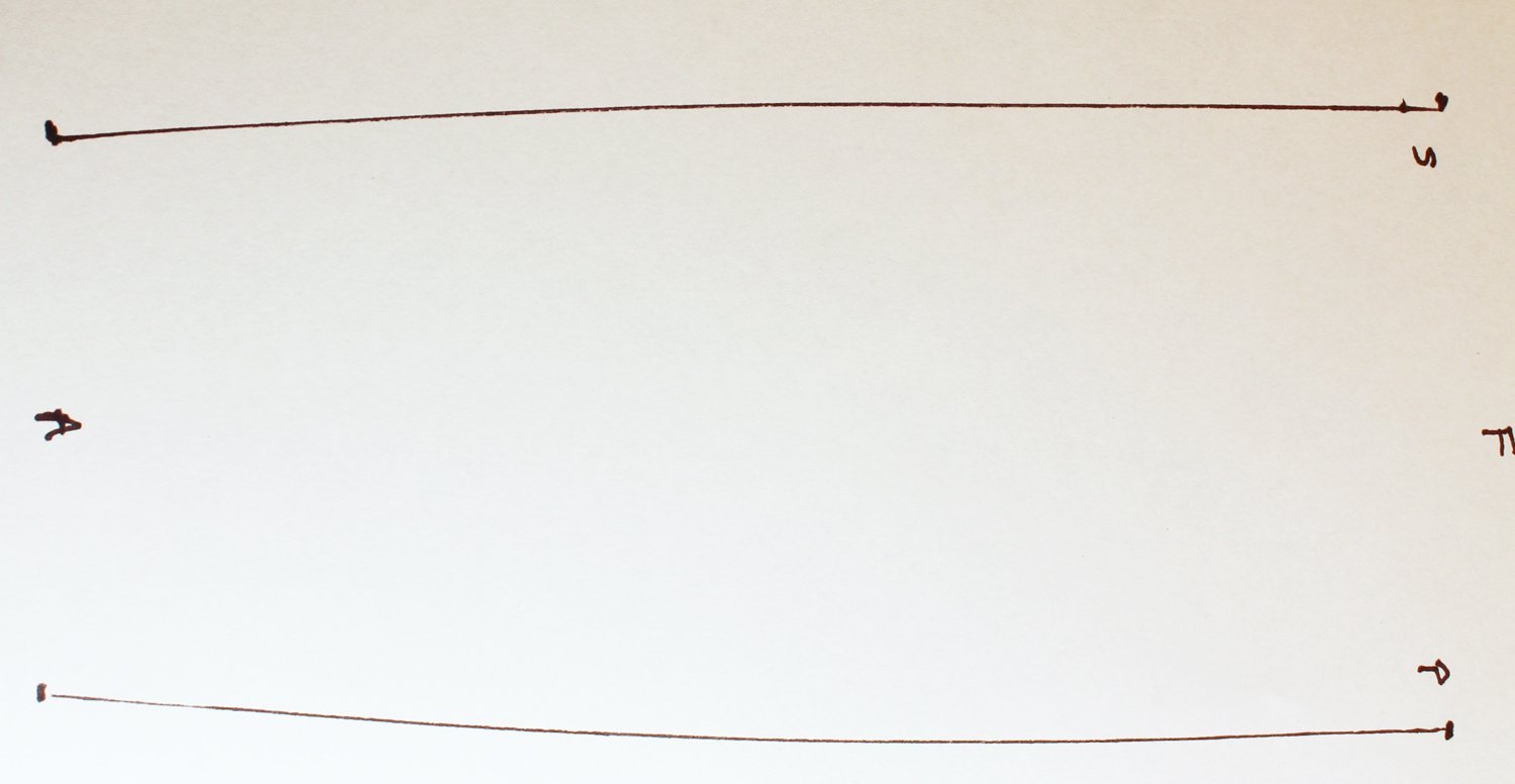
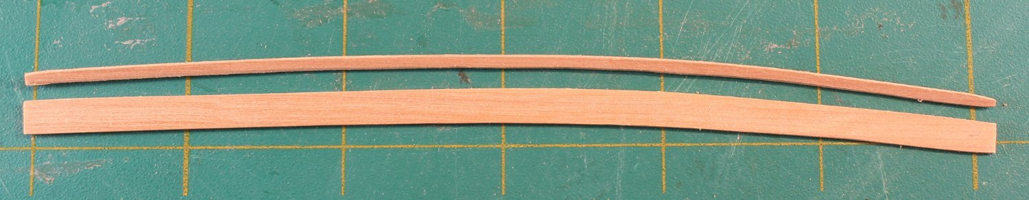
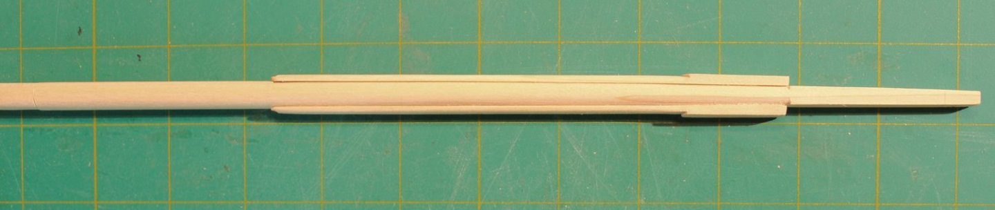
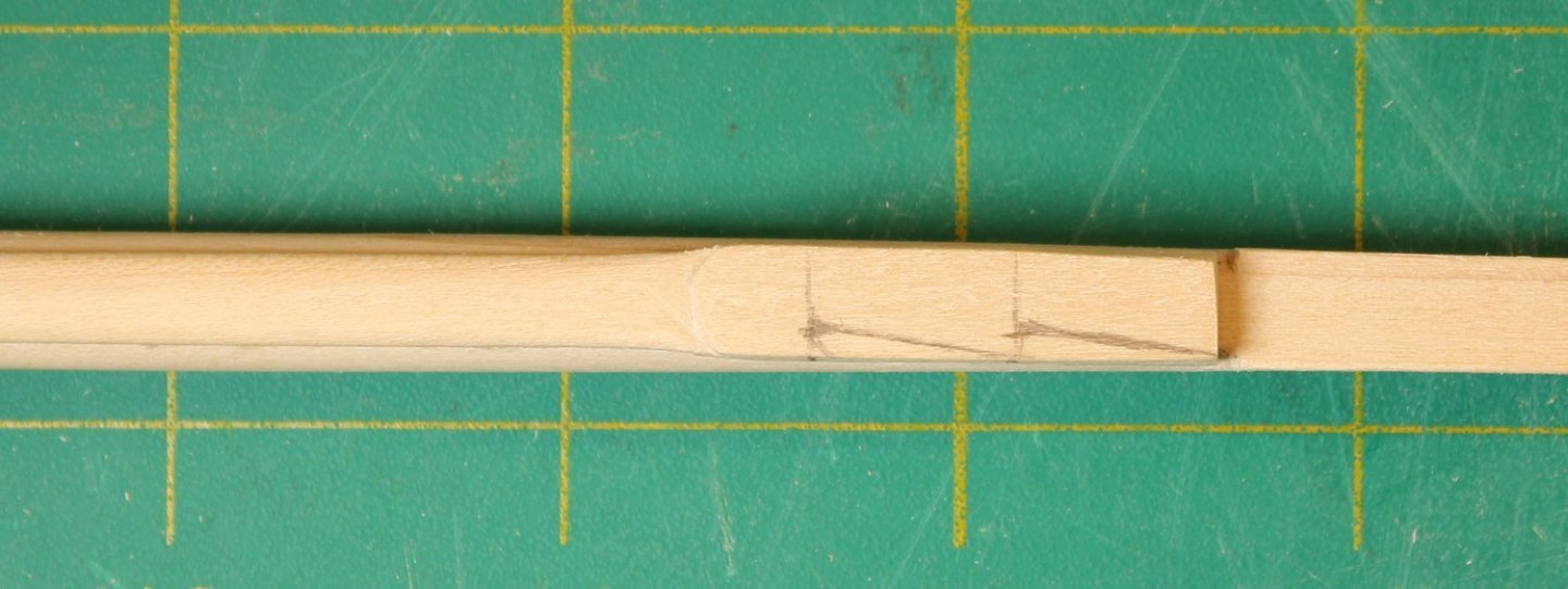
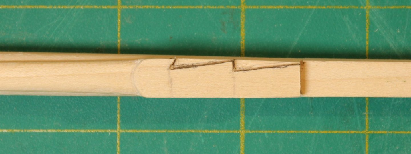
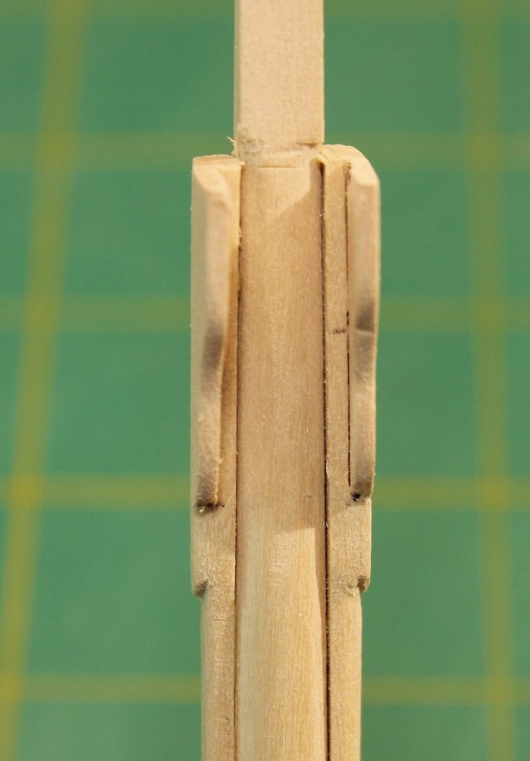
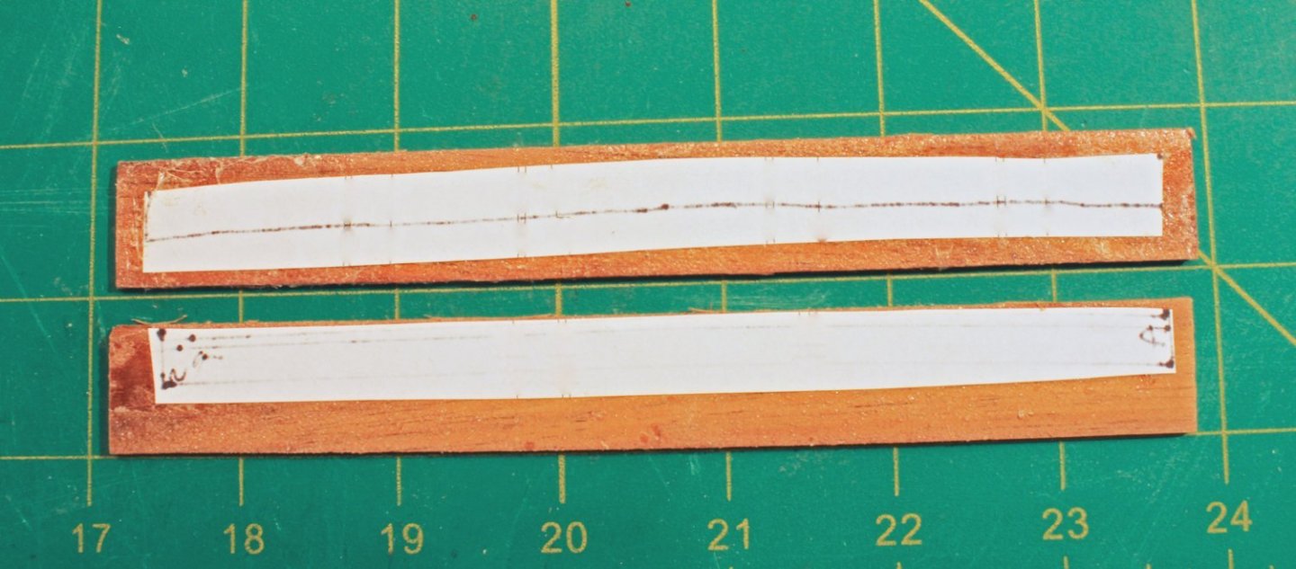
The cheeks are located on either side of the mast. Their inner surface is flat so the sides of the mast will need to be flattened. On this ship they are 25 feet long and extend from the bottom of the mast head to approximately 12 feet above the deck. At this scale, that is 6.25” long, ending 3” above the deck. A template is included in the practicum. The upper part of the cheek is called the hounds and is thicker than the rest of the cheek. The photo shows the cheek before and after shaping. The outline of the cheek was drawn onto both sides of the mast. This outline marks where the mast needs to be flattened. The hounds remain flat but the rest of the cheeks were rounded over. The apparent concavity in these cheeks below the hounds is an optical illusion. 0 The cheeks were then glued to the mast. Look at the straight line extending up the mast on the side view and the step-off above the hounds fore and aft. The next step was to make and install the bibs. These are forward extensions of the hounds and their purpose is to support the trestle trees. They are the same thickness as the hounds and are attached with a morticed scarf joint for strength. This is how I made the mortice. Start by drawing the zig-zag mortice onto the hound. It extends approximately three-quarters of the length of the hounds. Because the lower end of the bib is curved, the bottom mortice cut is also curved. Since I was using basswood, I used a #11 blade to inscribe the mortice. I did this a few times, deepening the cut with each pass. Once I was halfway through the hound, I used a chisel to remove the wood from the mortice. I have used pencil to make the joint more visible for you. This joint would not have been caulked and so the joint would not be very visible. It is important to keep the sides symmetric. Next, I drew the bibs on paper. The top of the bibs is 3/8” wide and it is half the thickness of the cheek. I laid the paper over the hounds and made a pencil rubbing of the mortice to get the shape of the tenon. Each side will be slightly different so two templates were needed. The one below is marked “S” for the starboard side. The front edge of the bibs was rounded over and installed; the top edge was left flat. There is a forward angulation to the bibs to allow the trestle trees to rest on them parallel to the water line. The top edge of the hounds and bibs should form a straight line.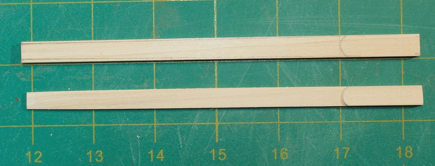


- 30 replies
-
- 23
-
-
-
- rigging/masts
- NRG
- (and 1 more)
-
Welcome back! For templates I will use a combination of taping small pieces of paper together for one side and inserting the paper between the frames for the unplanked side. Still requires some tweaking, but it compensates for the thickness of the planking and any asymetry between port and starboard.
- 869 replies
-
- 4
-
-
- hahn
- oliver cromwell
- (and 1 more)
-
NRG Rigging Project by tlevine
tlevine replied to tlevine's topic in - Kit build logs for subjects built from 1751 - 1800
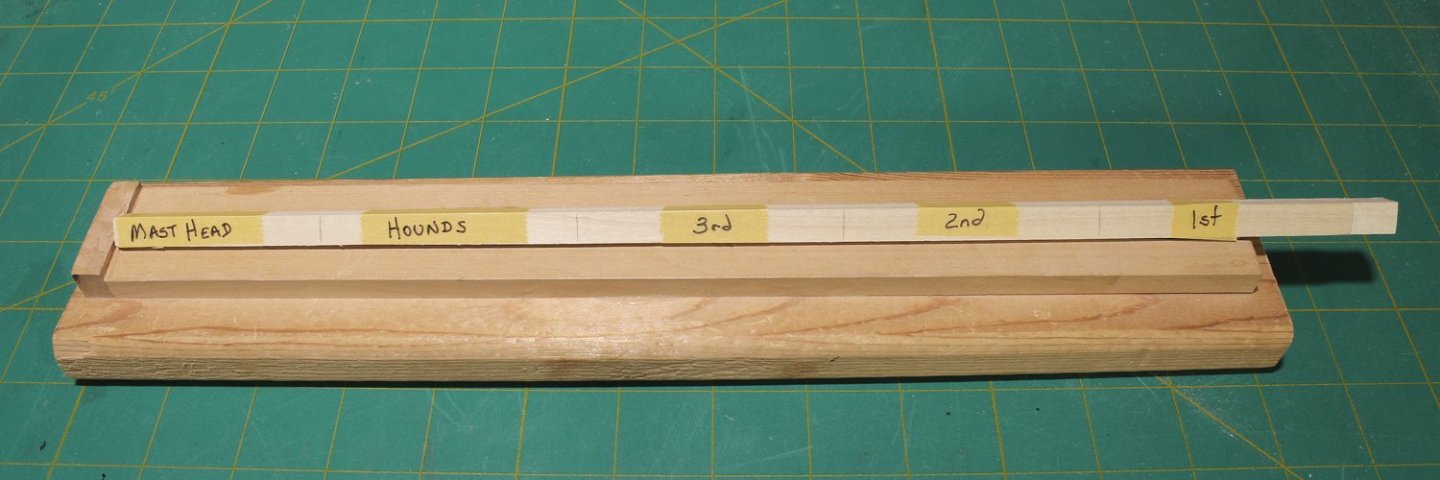
Masts are not the same diameter or shape from the mast step to the masthead. The Royal Navy had exact specifications for every section of the masts and yards and their rigging. Real masts were made up from multiple pieces of wood. This increased their strength and allowed the use of smaller diameter trees. My mast was made from a square poplar dowel purchased at a big box home improvement store. The mast head is square and the rest of the mast is initially round. To transform a square dowel into a round mast, the dowel will first be shaped into a regular octagon (all sides the same size). The instructions will go into detail on how to do this and will also include a scale template of the mast shape. It is easier to shape the mast if you have extra wood on both ends. I cut the dowel approximately 2” longer than the length of the mast. For the kit, glue 1-2 inches of scrap wood, the same or smaller diameter than the dowel, on both ends. The dowel was sanded down to just fit into the slot in the backbone. I used a level to make sure it was vertical. The dowel was removed and I drew the centerline on all four faces. Then, using the centerline as a guide, the templates were tack-glued to two adjacent sides of the dowel and the outline of the template was drawn onto the dowel. The templates were removed and I marked the transition from the round lower part of the mast to the square masthead with a few turns of masking tape to prevent damaging the masthead. I shaped the dowel below the masking tape to match the outside edge of the template with a chisel. The quarters were marked on all four faces of the dowel. The 7:10:7 ratio was drawn in at the quarters and a few other locations. I took the measurements directly from the template. Lines were drawn connecting those marks from the bottom of the mast up to the masking tape. You can see the marks in the photo. The wood outside those lines was removed with a chisel. Two very important things to keep in mind: your tool must be sharp and, as much as possible, the wood should be removed going with the grain. I rotate the dowel frequently, rather than finish one edge at a time. When using wood without discernable grain, it can be difficult to see the edge of the octagon. So when I am getting close to the lines, I run a pencil along the edge. You can see how well the jig holds the mast securely. And here is the final result. You can see how the tape protected the masthead. Now that the lower part of the mast has been shaped, it was time to start shaping the mast head. On the actual mast, the sides of the mast head are cut down, leaving the full thickness fore and aft. Then, after the cheeks are installed on the sides of the mast, the mast head is built back up to a square shape. The next photos show the mast head before and after the wood had been removed from the port and starboard faces. On the fore and aft sides of the mast head, I removed the wood outside the pencil lines, continuing the taper of the lower part of the mast. The next two pictures show the mast head marked out and tapered. Compare the appearance of the fore/aft faces versus the port/starboard ones. You will also notice that I have started to flatten the sides of the mast in preparation for the cheeks. Tapering the mast head was done with the Byrnes sander. Otherwise, this was all done with hand tools.


- 30 replies
-
- 21
-
-
- rigging/masts
- NRG
- (and 1 more)
-
NRG Rigging Project by tlevine
tlevine replied to tlevine's topic in - Kit build logs for subjects built from 1751 - 1800
The lower mast and trestle trees must be made before installing the lower deadeyes. There are many ways to make masts and yards, including using a round dowel approximately the right diameter, turning a wood blank on a lathe or chucking a dowel into a drill and sanding it down to the correct dimensions. A fourth technique will be shown here. The only tools required are a caliper, a sharp chisel or plane and sandpaper. A jig is needed to hold the wood during the shaping process. The picture below shows two types of jigs. The top two homemade jigs only differ in the diameter and length of wood they can hold. The lower jig was made by Hobbymill, which is no longer in business. It is a single jig with multiple sized slots. I prefer the security of the single size jig. With either type of jig, the final diameter of the mast or yard must be greater than the height of the V-slot on the jig. The practicum will give instructions for making the jig. Before going any further, a few terms need to be defined. The part of the mast above the trestle trees is called the mast head. Below the trestle trees, the mast is divided into “quarters”, starting at the mast step in the hold. “Cheeks” (not illustrated) run on either side of the mast below the mast head and provide additional strength to the mast. The “hounds” are the upper parts of the cheeks. Later era ships have a “fish”, similar to the cheek but located on the fore side of the mast. The relative length and shape of these pieces vary by size and type of ship, country and era.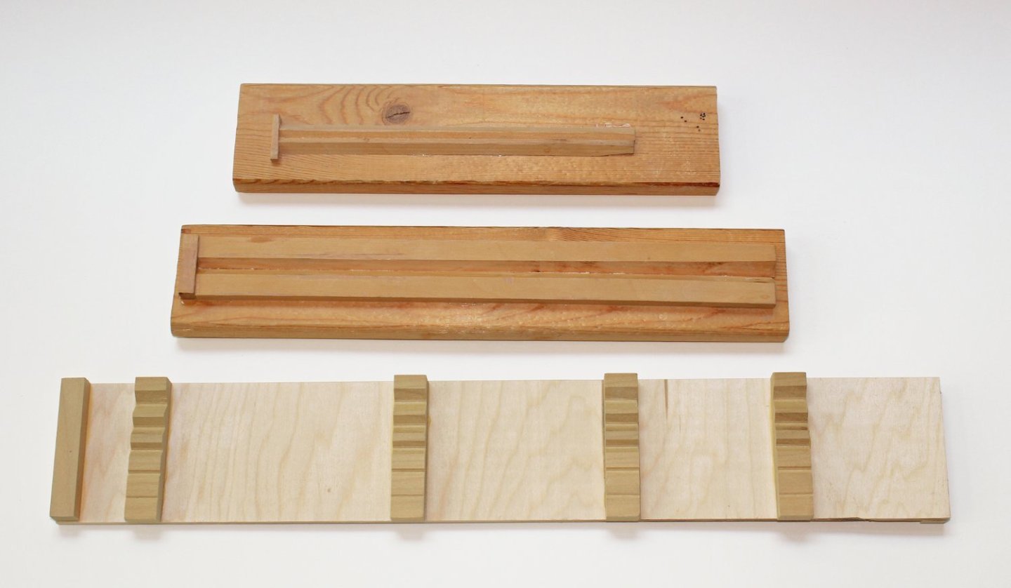
- 30 replies
-
- 23
-
-
- rigging/masts
- NRG
- (and 1 more)
-
NRG Rigging Project by tlevine
tlevine replied to tlevine's topic in - Kit build logs for subjects built from 1751 - 1800
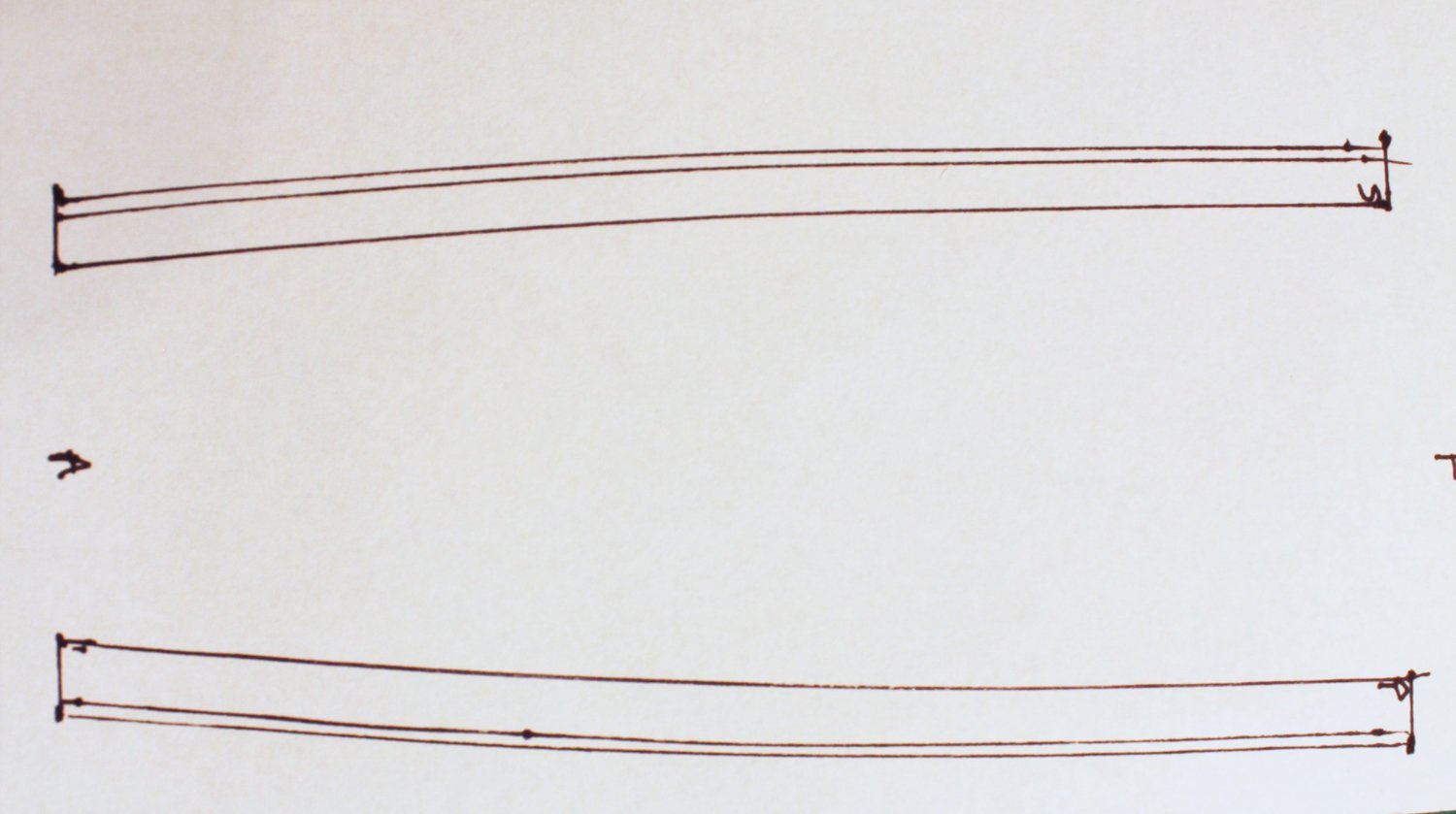
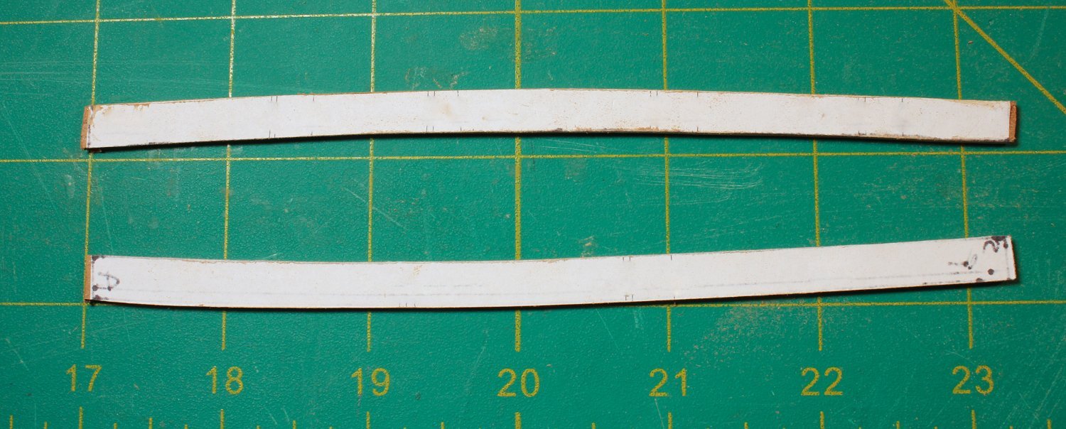
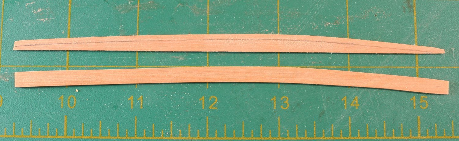
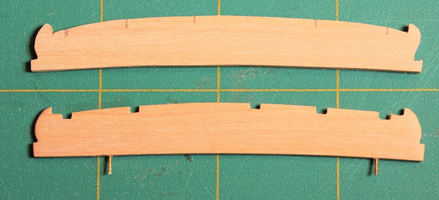
This ship’s main mast channels are 13’ long, 18” wide and 4” thick. They are made by laminating three layers of 1/32” sheet together. The middle layer’s grain is oriented 90 degrees to the outer layers for added strength. I weighted the channel down while it was drying to prevent warpage. In actual practice, there would be a slight taper of the channel from the hull to its outer edge, but for this project I ignored that. The fore end of the channel is located just behind the aft side of the mast. There are recesses cut into the fore and aft ends of the channel. The deadeye strops fit into mortises cut into the channel and a decorative strip holds everything in place. The channel template shows the locations of the deadeye strop mortices. The location of the fore end of the channel was marked on the hull. It is 2.5 feet below the rail and runs parallel to the wale. Templates were used to get the exact shape. I used the template from making the cap rail as a starting point and modified it to exactly fit the shape of the hull. The openings for the deadeye strops were made by cutting shallow grooves into the channel and connecting them with a 2 mm chisel. A #11 blade will also work. The location of frames 4 and 6 were marked on the inner edge of the channel and 22-gauge brass wires were inserted at those spots for strength. The fore and aft edges were rounded over but the long outer edge was kept sharp. You may have noticed that the deadeyes are not evenly spaced. On the actual ship, a gunport was located between the third and fourth deadeyes. I decided to keep things simple and not model the gunport. If you want, the spacing between frames 5 and 6 will allow you to add one.With the channel installed, a clear finish was applied to the exterior of the hull. After the finish dried, I sanded the long outer edge of the channel to remove the finish. This will help adhesion when the decorative strip is added after the deadeyes are installed.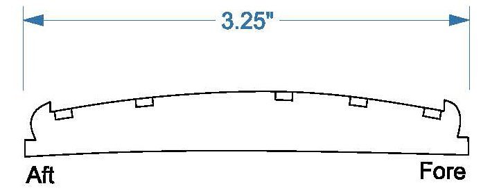

- 30 replies
-
- 16
-
-
- rigging/masts
- NRG
- (and 1 more)
-
NRG Rigging Project by tlevine
tlevine replied to tlevine's topic in - Kit build logs for subjects built from 1751 - 1800
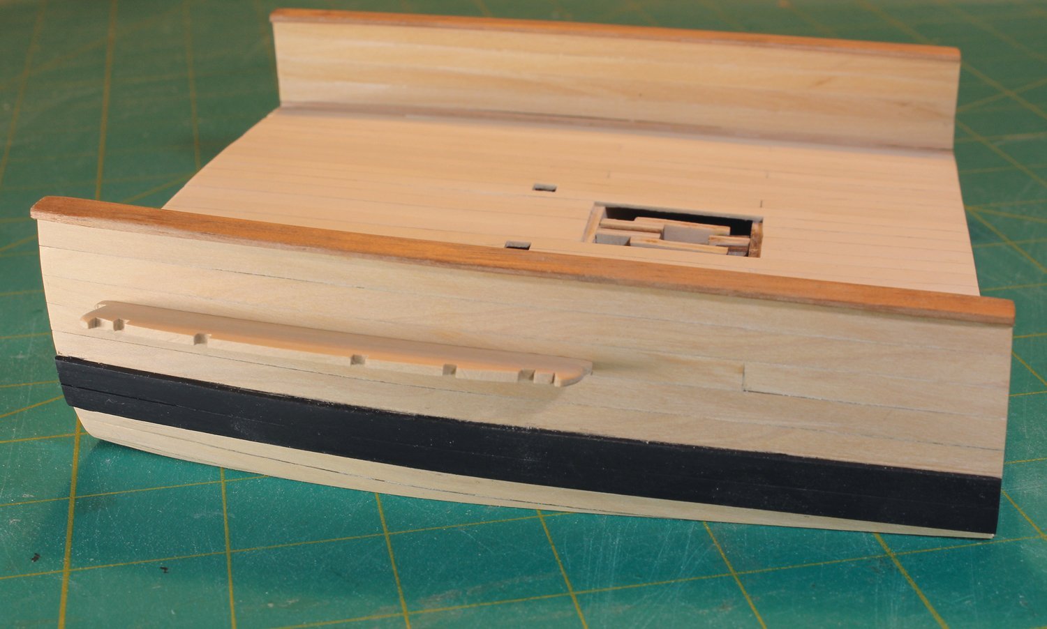
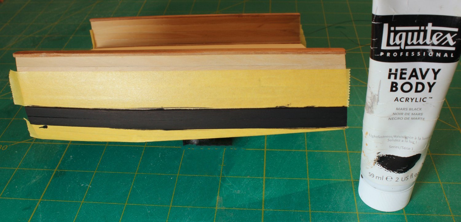
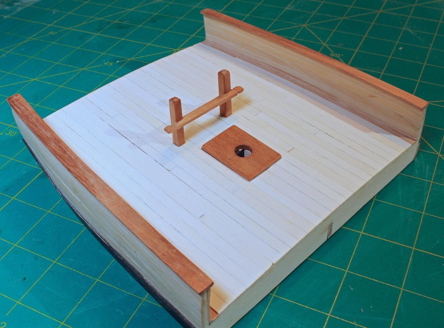
The bit pins are 9” square posts. The crosspiece is 8’ x 10” x 3” and connects the two pins. It is morticed into the pins 3’ above the deck. Shape the ends of the crosspiece as seen in the picture. I raided my scrap box again for these pieces but the kit will contain the correct thickness of basswood to construct them. I used the previously drilled pilot holes to locate the centers of the bitt pins and lightly traced the outline of the bitt pin onto the deck. A series of holes was drilled inside the outline and they were connected with a #11 blade. They were enlarged with files until the openings were just large enough to allow the bit pin to pass through them. They will not be permanently installed until later to make installing the mast easier. This is how the model looks with everything temporarily installed. Other than installing the channels, the hull is complete. Next, the wale was painted. The hull planking was masked off above and below the wale. I used three coats of artist’s acrylic paint diluted 1:3 paint to water, sanding with 400 grit sandpaper between coats. I remove the tape as soon as the last coat has been applied to prevent paint adhering to the tape.

- 30 replies
-
- 21
-
-
-
- rigging/masts
- NRG
- (and 1 more)
-
NRG Rigging Project by tlevine
tlevine replied to tlevine's topic in - Kit build logs for subjects built from 1751 - 1800
Hopefully, soon, Chuck.- 30 replies
-
- 9
-
-

-
- rigging/masts
- NRG
- (and 1 more)
-
NRG Rigging Project by tlevine
tlevine replied to tlevine's topic in - Kit build logs for subjects built from 1751 - 1800
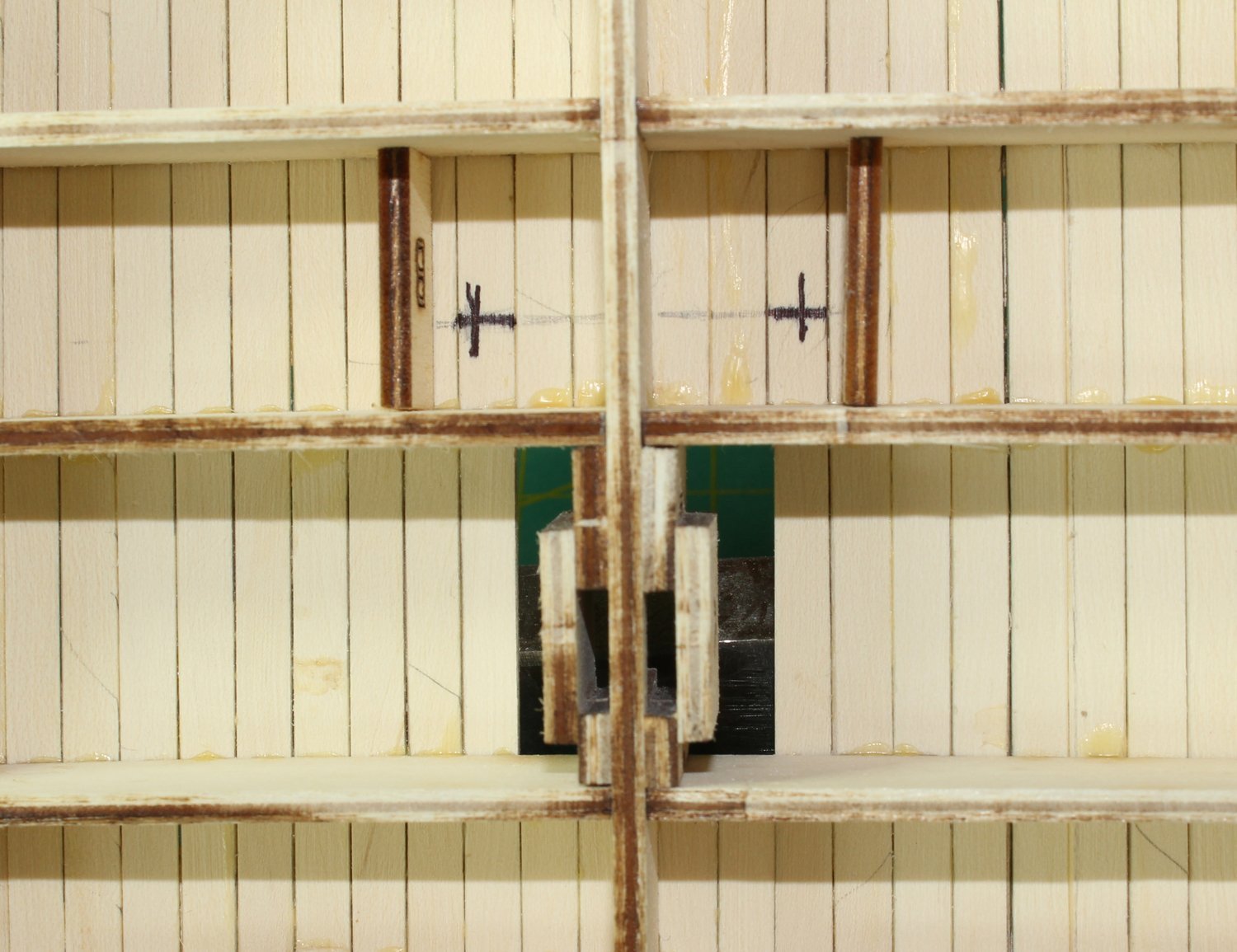
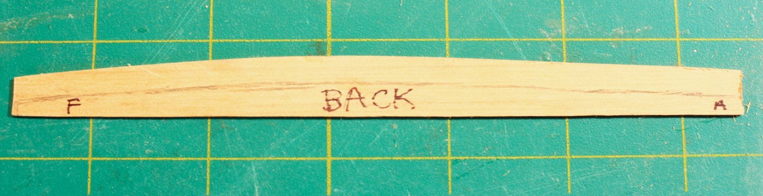
As I mentioned before, the bit pins will be glued to the “B” spacers. I measured and marked two feet (½” scale) aft from the aft surface of Frame 4 and nine inches (3/16” scale) inboard from the spacers. These are the centers of the bit pins. Small pilot holes were drilled up through the deck. I planked the inner bulwarks, starting at the waterway, using ten-inch-wide planks. I applied a clear finish at this point. The top of the bulwarks was sanded flat in preparation for installing the cap rail. Simply turn the model upside down and sand the bulwark the way you did the base. This also gives a fresh surface to glue the top rail onto. Templates were made to determine the shape of the rail. This is how I made these. Masking tape was run along the upper edge of the hull planking to prevent marking the wood. The model was turned upside down and, hugging the side of the ship, a line was drawn along the top of the hull. Don’t forget to mark fore and aft, port and starboard. The rail is 12” wide with a 1” overhang inboard and outboard. I drew lines 1” (0.02”) outboard and 11” (0.23”) inboard of the original line. The picture shows the templated line and the overhangs. I cut out the templates with a lot of extra paper on either side of them because long, narrow pieces of paper are prone to warping. They were glued to the 1/32” wood sheet. I use either Elmer’s glue stick or glue spray that is not water based (3M-45) to help prevent warping. Both of these adhesives can be removed with isopropanol and scraping. This is another opportunity to check out your scrap pile for a piece of contrasting color wood. Cut out the rails and mark the undersurface with the side and orientation before removing the template. Remove the template and round over the edges. If you want a contrasting color for the rails, paint or stain them before installing.


- 30 replies
-
- 25
-
-
- rigging/masts
- NRG
- (and 1 more)
-
NRG Rigging Project by tlevine
tlevine replied to tlevine's topic in - Kit build logs for subjects built from 1751 - 1800
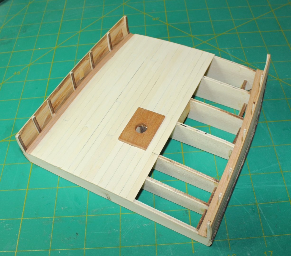
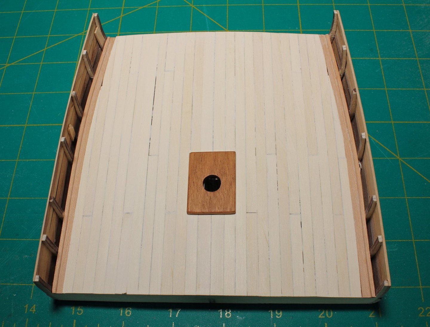
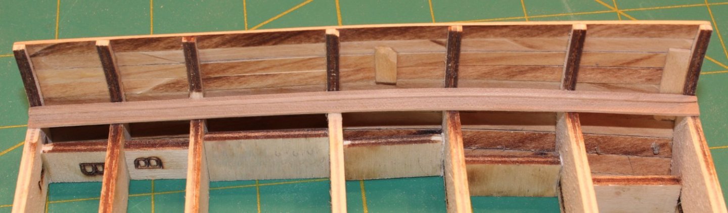
Next up was the deck planking. I marked the center line on the top of the frames and installed “B” spacers between Frames 4 and 5. These will be used later to secure the bit pins. This ship has a king plank on either side of the midline, which is wider than the regular planking, 12” instead of 10”. I shortened the mast partners so the planks would land on Frame 4. Just like I did for the hull planking, I used a pencil on one edge to simulate caulking and, because of the camber, sanded a bevel into the lower edge of the other side of the planks for a tight fit. A row of 10.5” planking was installed on either side of the king planks. The rest of the planks will be 10” but this allowed the edges of these planks to be aligned with the outer edge of the partners. I removed the partner to prevent it from getting damaged. This is why it was only tack glued. I used a four-step butt joint pattern for the rest of the deck planking. The rest of the planking was installed, tapering the outermost rows to fit against the waterway.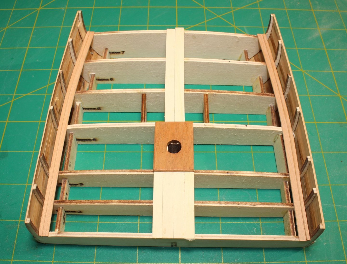

- 30 replies
-
- 22
-
-
- rigging/masts
- NRG
- (and 1 more)
-
NRG Rigging Project by tlevine
tlevine replied to tlevine's topic in - Kit build logs for subjects built from 1751 - 1800
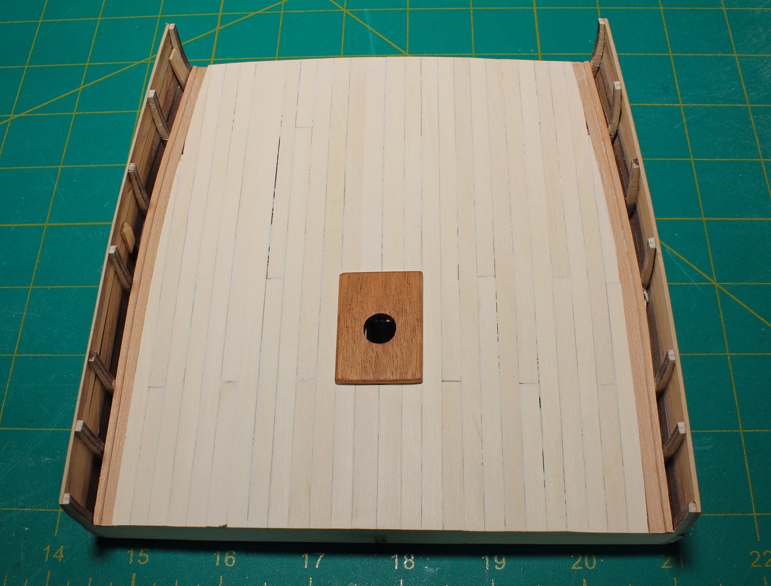
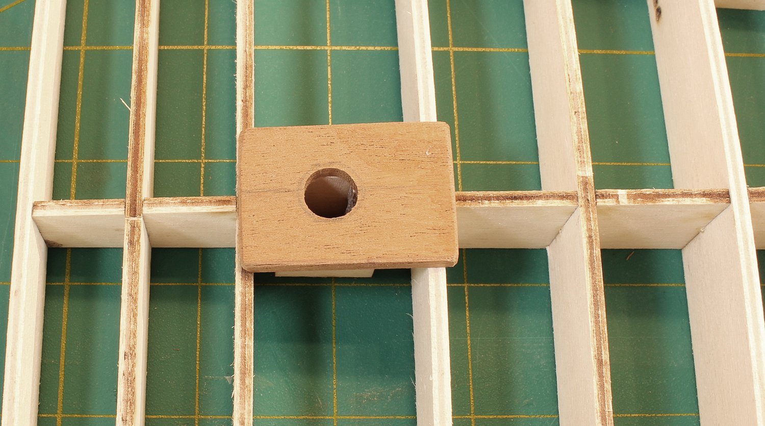
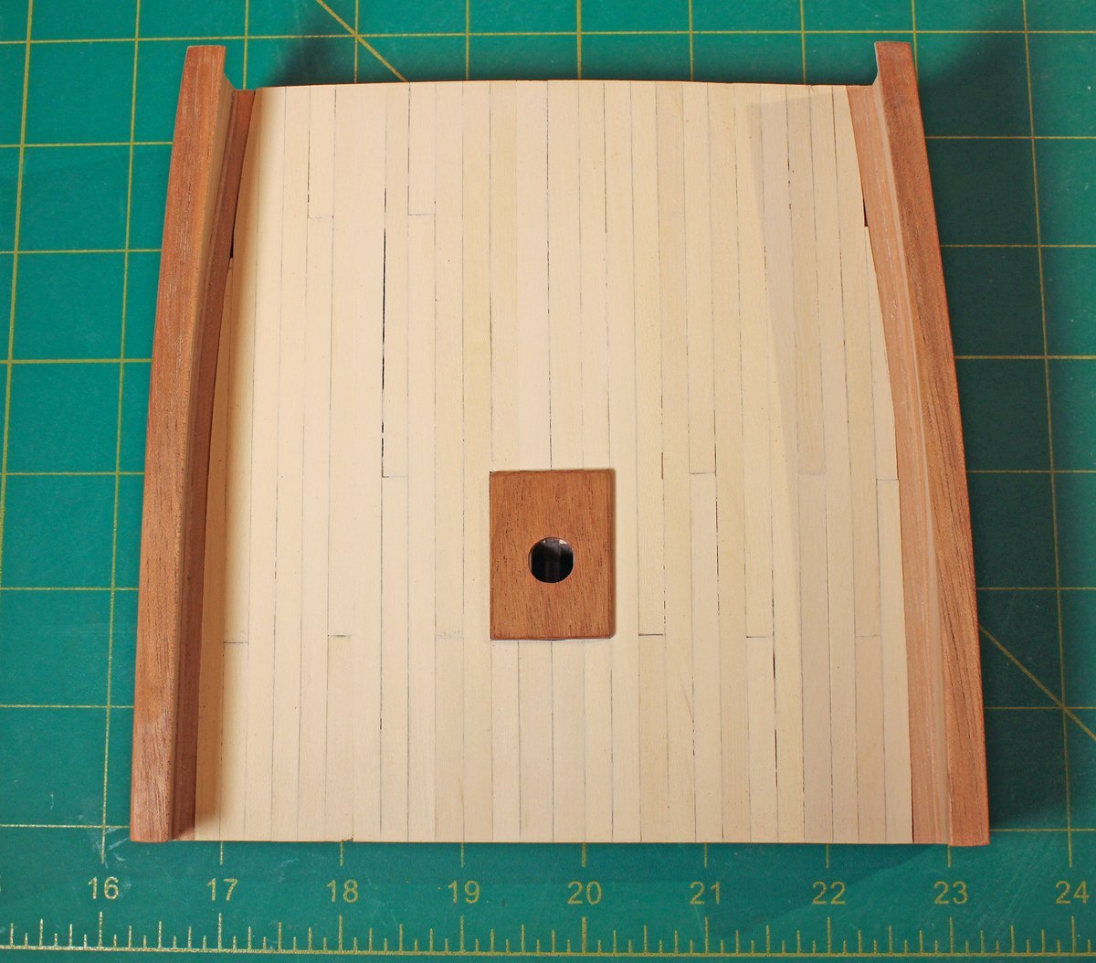
The next stage of construction was fitting out the mast partners, inner bulwarks, and deck. On a real ship, the mast partners were made up from several pieces of wood. For simplicity, I made the mast partners from single piece of cherry from my scrap box. In the kit, it is made from two pieces of 1/32” basswood, with the two pieces oriented 90 degrees to each other for strength. It measures 5’6” x 4’ x 3”. The center of the mast is located 6” forward of the center point of the partners, to allow enough room for four eyebolts aft for securing the truss pendants and lifts. It is not 100% historically accurate but compromises had to be made during kit design. The mast is 17.5” in diameter at the partners and is raked aft so the opening will be oval, not round, with the long axis fore and aft. I began by drilling a hole smaller than the final dimension. It will be finessed later. Remember, you can always remove more wood...you can't put it back. Then the edges and corners were rounded over. The waterway was made from two pieces of wood laminated together. Because of the amount of hull curvature, I prefer to make a template and cut the outline of the bulwark onto a sheet of wood rather than edge-bend. The template is very simple: a piece of paper which is gradually trimmed to the correct shape. You only need one template since the two sides are mirror images of each other. The outboard edge of the waterway was traced onto the 1/32” basswood sheet and cut. Using a compass, a line was the drawn 10” inboard and the waterway was cut out. I prefer to make all my marks on the undersurface of the wood, where they will not be seen. All four surfaces were sanded smooth, keeping the edges sharp. Using the same template, I drew the outboard line on a second piece of basswood and cut it out. A second line was drawn 4” inboard. This was cut out and sanded but the upper-inner edge was rounded over. The pictures show both pieces of the waterway. The first layer of the waterway was installed and because a template was used, it fits perfectly and without tension. After the first piece was dry, the second narrow piece was added next to the bulwark, rounded over edge inboard.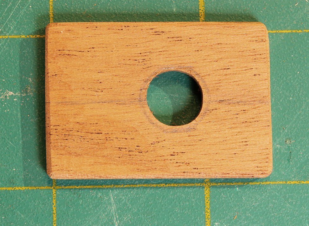


- 30 replies
-
- 25
-
-
-
- rigging/masts
- NRG
- (and 1 more)
-
NRG Rigging Project by tlevine
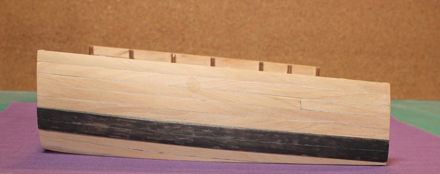
tlevine replied to tlevine's topic in - Kit build logs for subjects built from 1751 - 1800
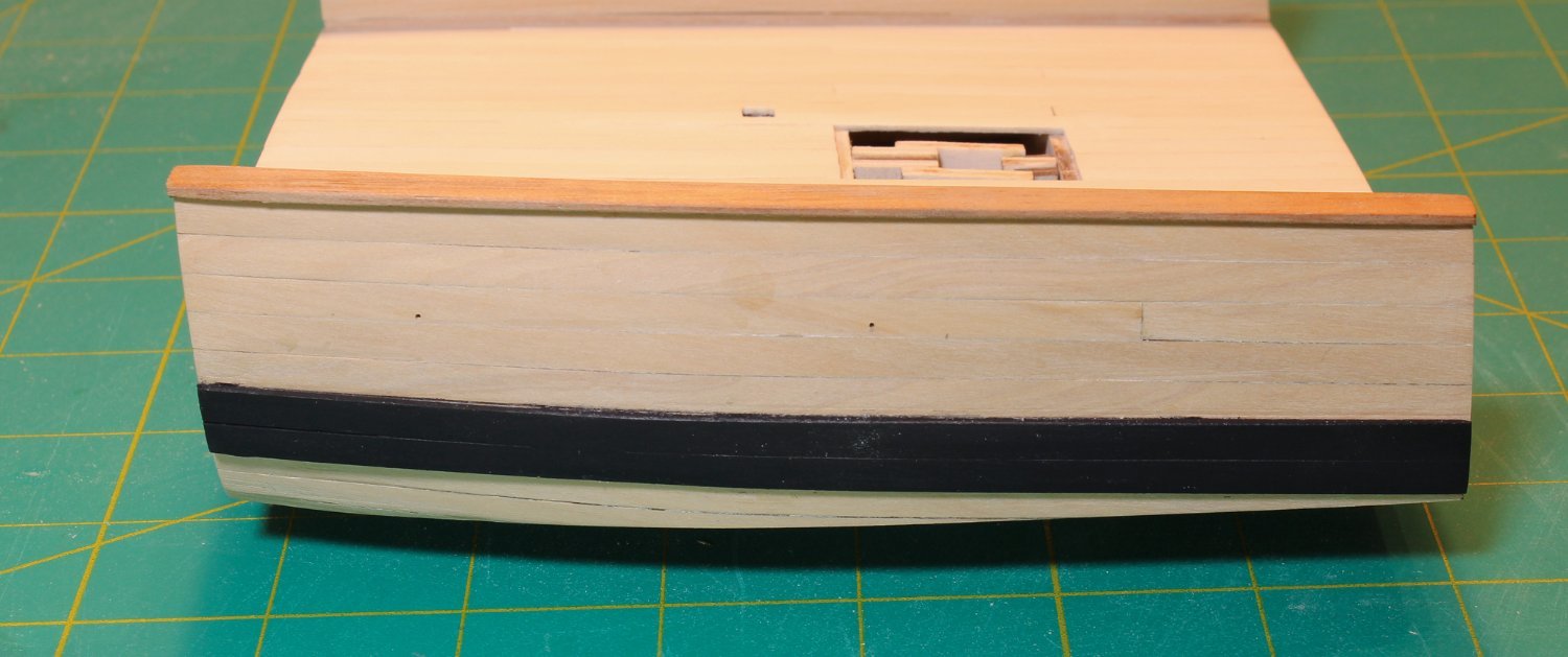
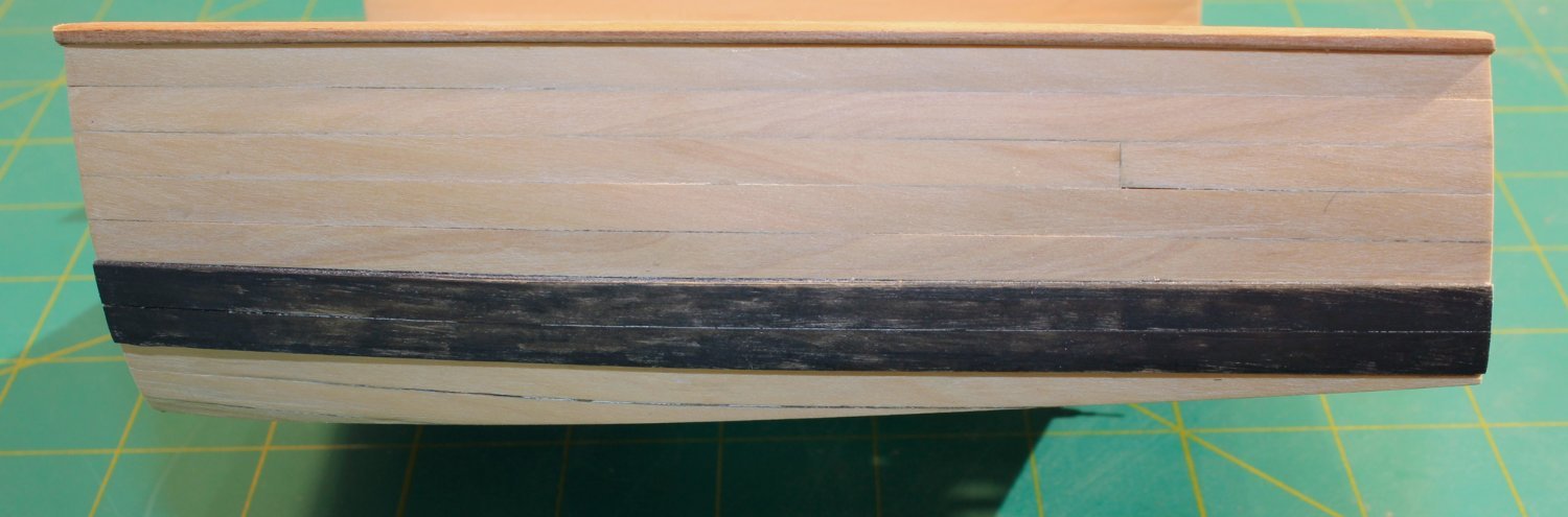
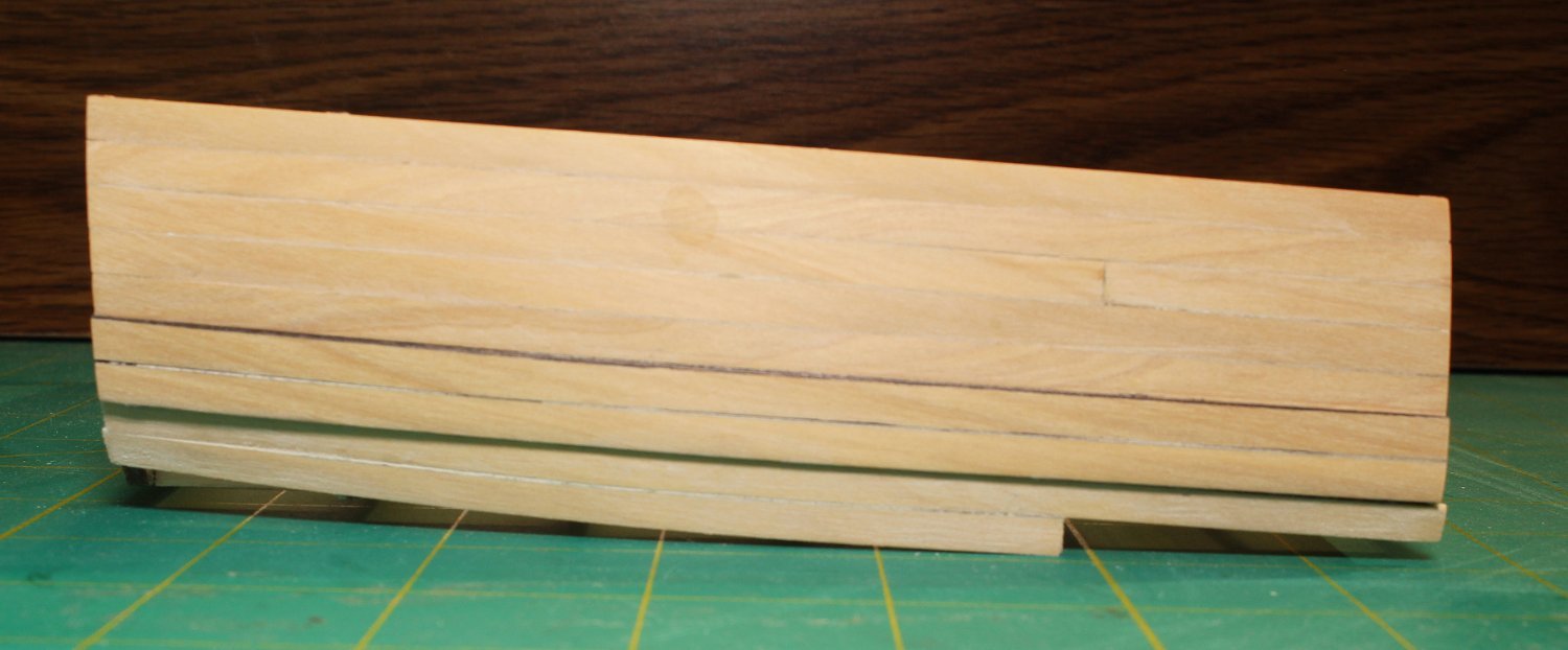
Thanks everyone. When starting this project I wavered between a dummy hull and a simple POB cross section. One of the advantages to this approach is that it results in a nice desktop model. The compromise is that certain lines, like the stays, are omitted. It is time to plank the hull. The kit contains enough 1/32” basswood sheet to plank the hull and deck. I began the planking at the top of the bulwark extensions. This made them less susceptible to breakage. There are five rows of planking, followed by two rows of double-thick planks for the wale. Below the wale, the rest of the planking is the same thickness as the upper part of the hull. All the planks are the same ten-inch width. The thin basswood can easily be cut with a #11 blade and straight edge. No spiling necessary! I put a slight bevel on the long edge of one side of each plank to get a tight fit between the planks and rubbed a pencil along the other edge to simulate caulking. The picture shows the hull planked to the top of the wale. The wale is made from two rows of double-layer planking and will be painted black later. I painted the edges of both layers with an archival ink marker before installing them. After the first layer was installed, the hull was sanded fair. For the second layer of the wale, the exposed outer edges were slightly rounded over before painting the edges. The second layer of the wale was glued to the first layer and the surface was sanded smooth. I prefer not to paint the wale until the rest of the hull is completed to prevent damage. The rest of the planking below the wale was installed. Because some of the plank ends did not land on a bulkhead, it was necessary to glue a scrap of wood on the inner side of the plank to secure it to the plank above. In this picture, the first two rows lower planks have been installed. After the last row of planking had been installed, I removed most of the wood below the bulkheads by shaving it down with a razor blade. When most of the wood was removed, the model was put on top of a sheet of sandpaper and the bottom was sanded flat by moving the whole model back and forth. In this picture, the wale has been dyed with a coat of archival ink so you can see the difference in thickness between the regular planks and the wale.

- 30 replies
-
- 27
-
-
-
- rigging/masts
- NRG
- (and 1 more)
-
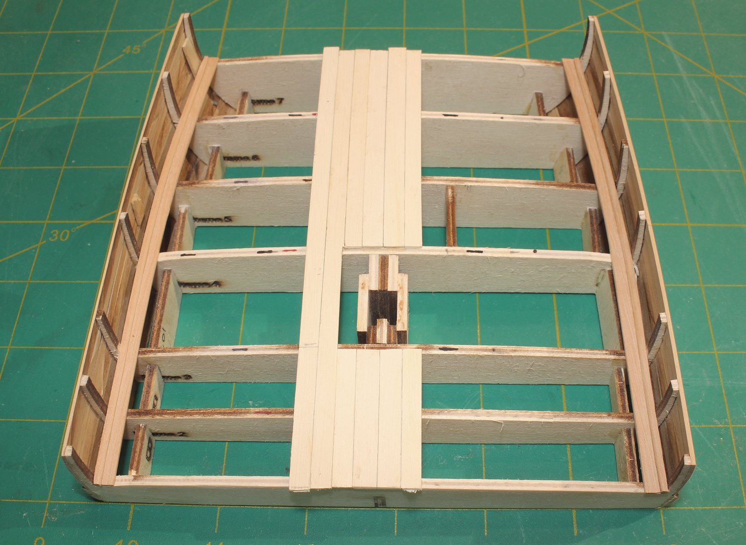
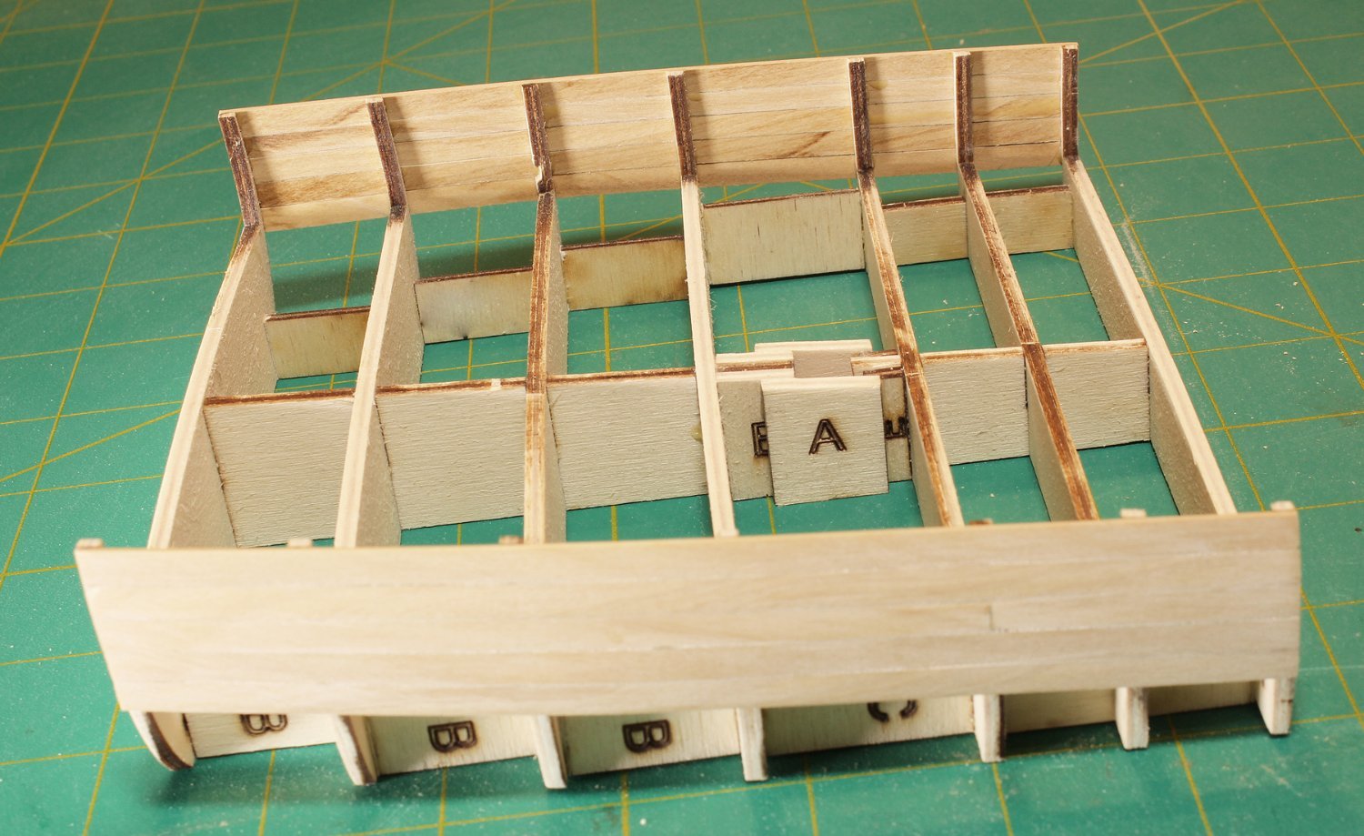
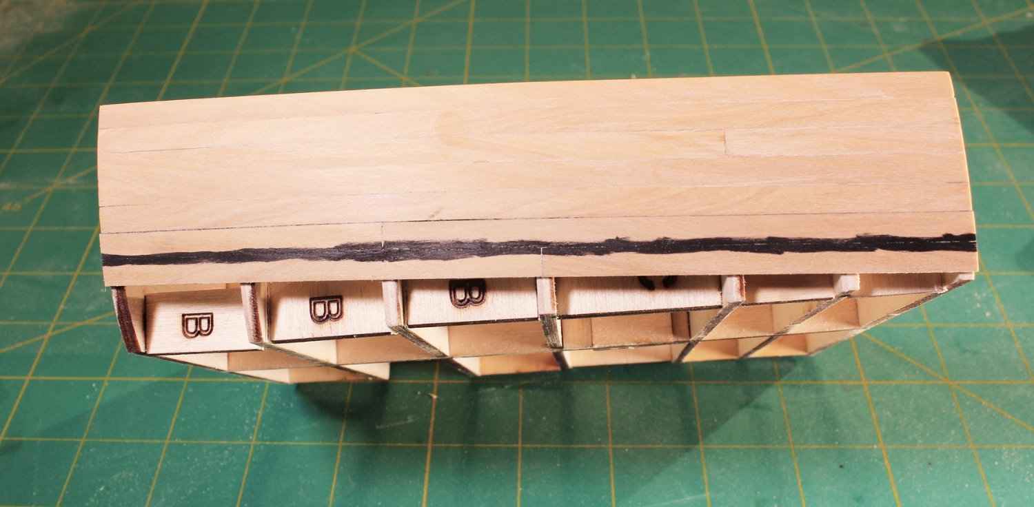
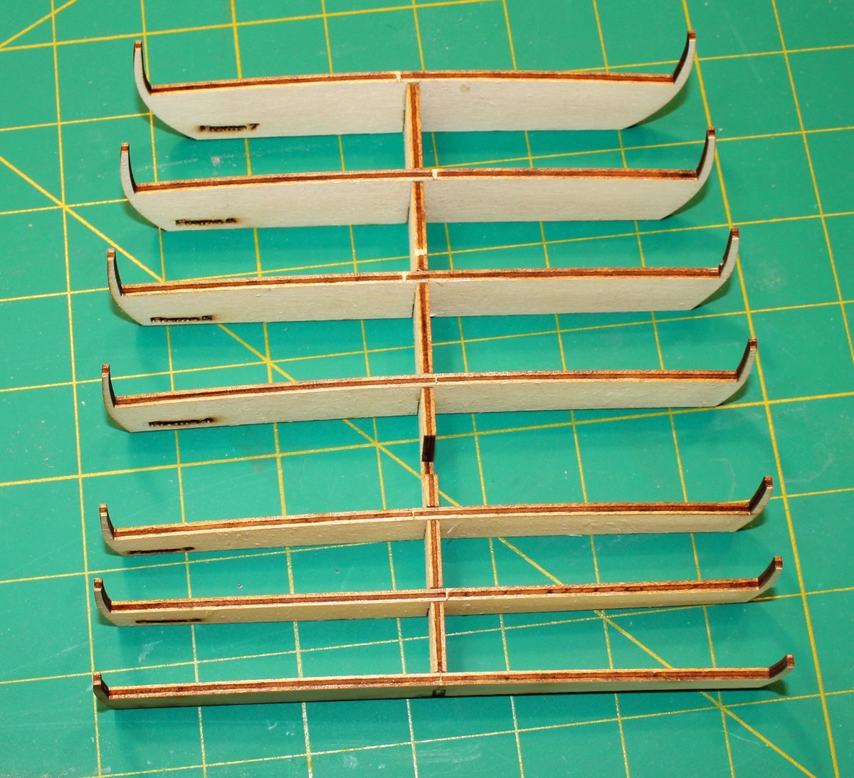
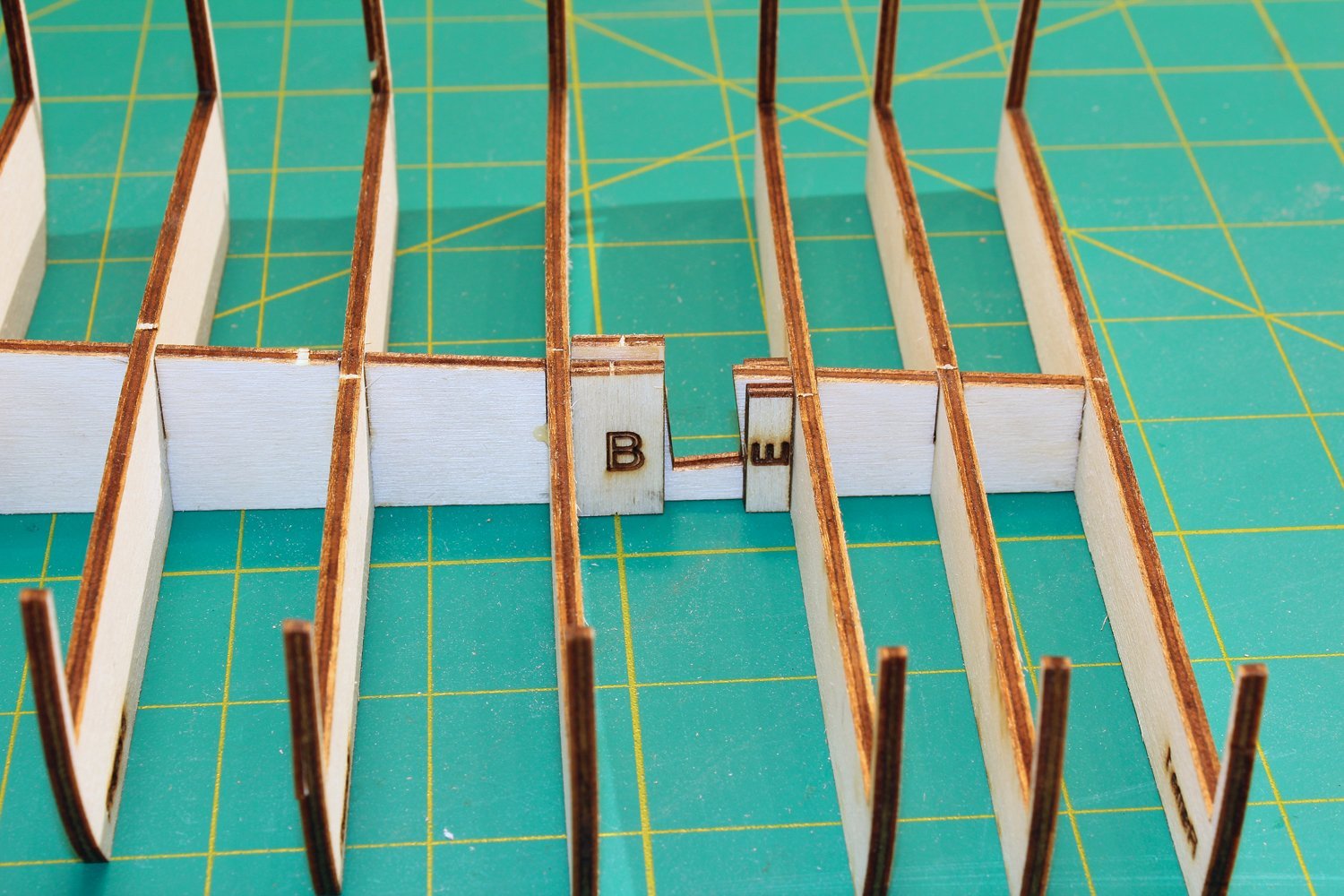
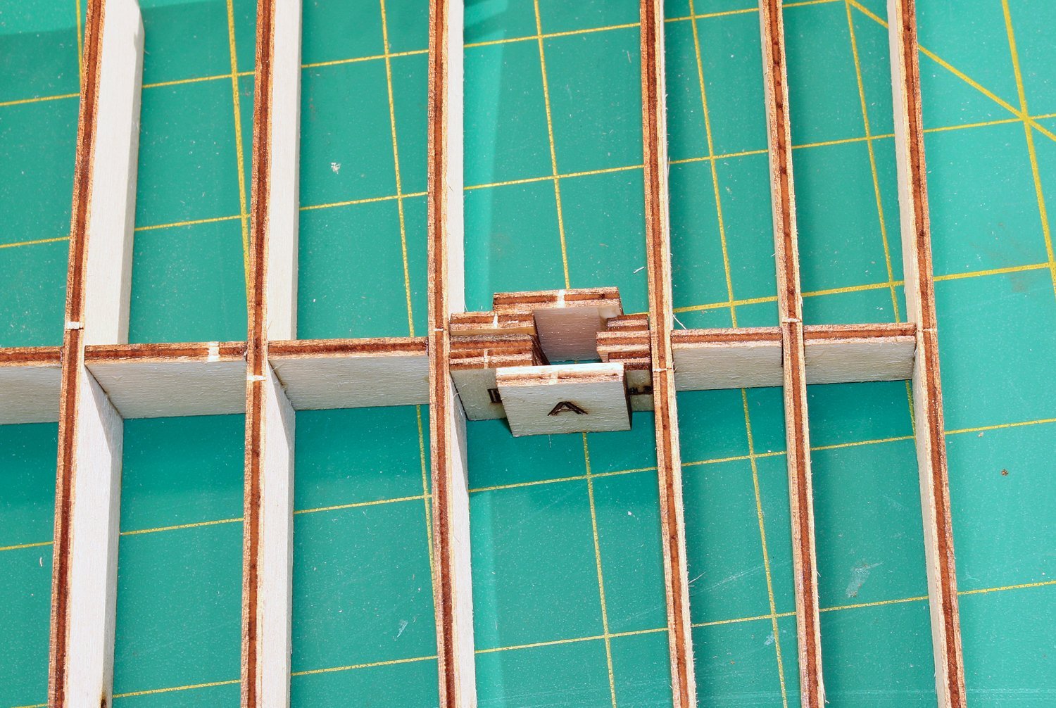
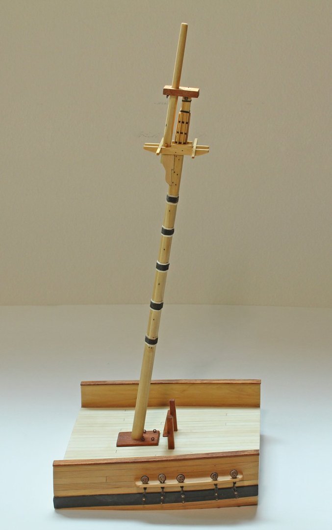
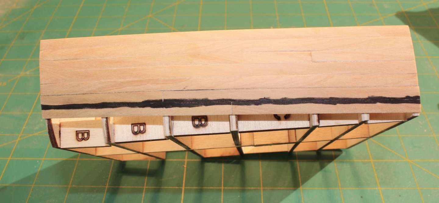
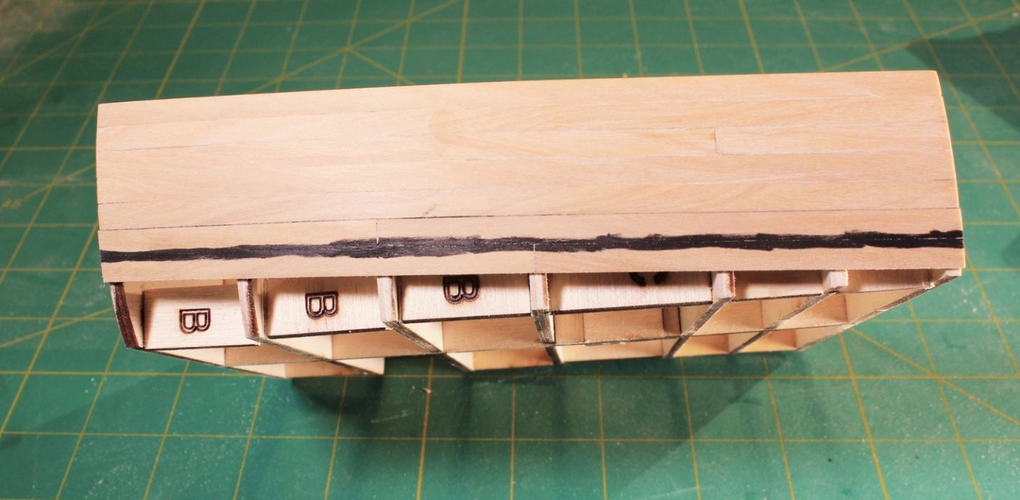
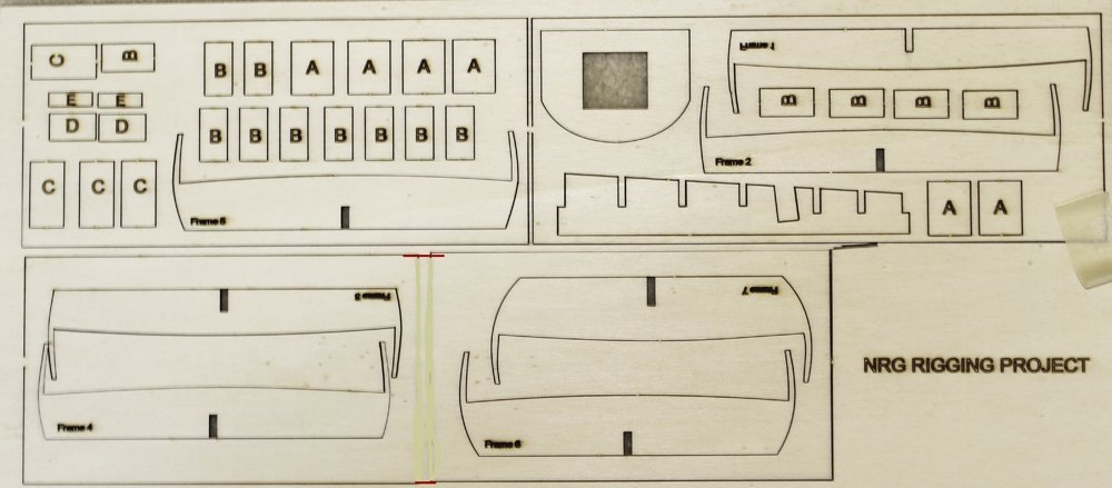
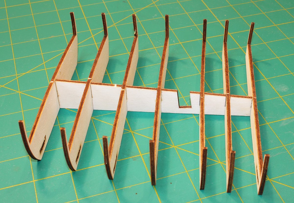
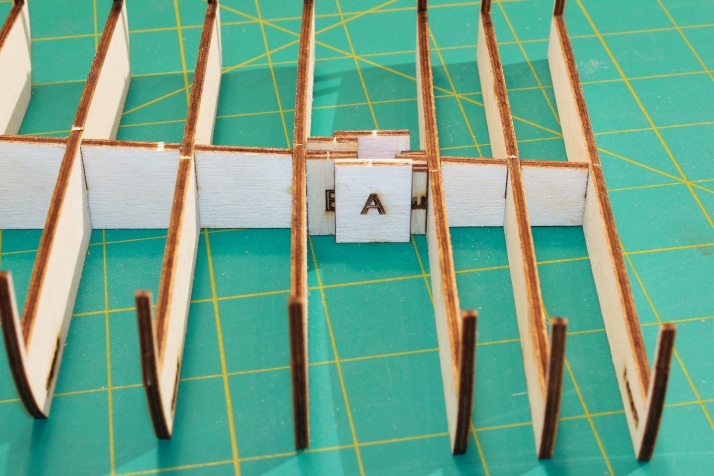
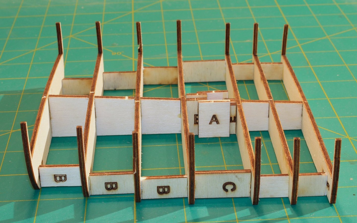
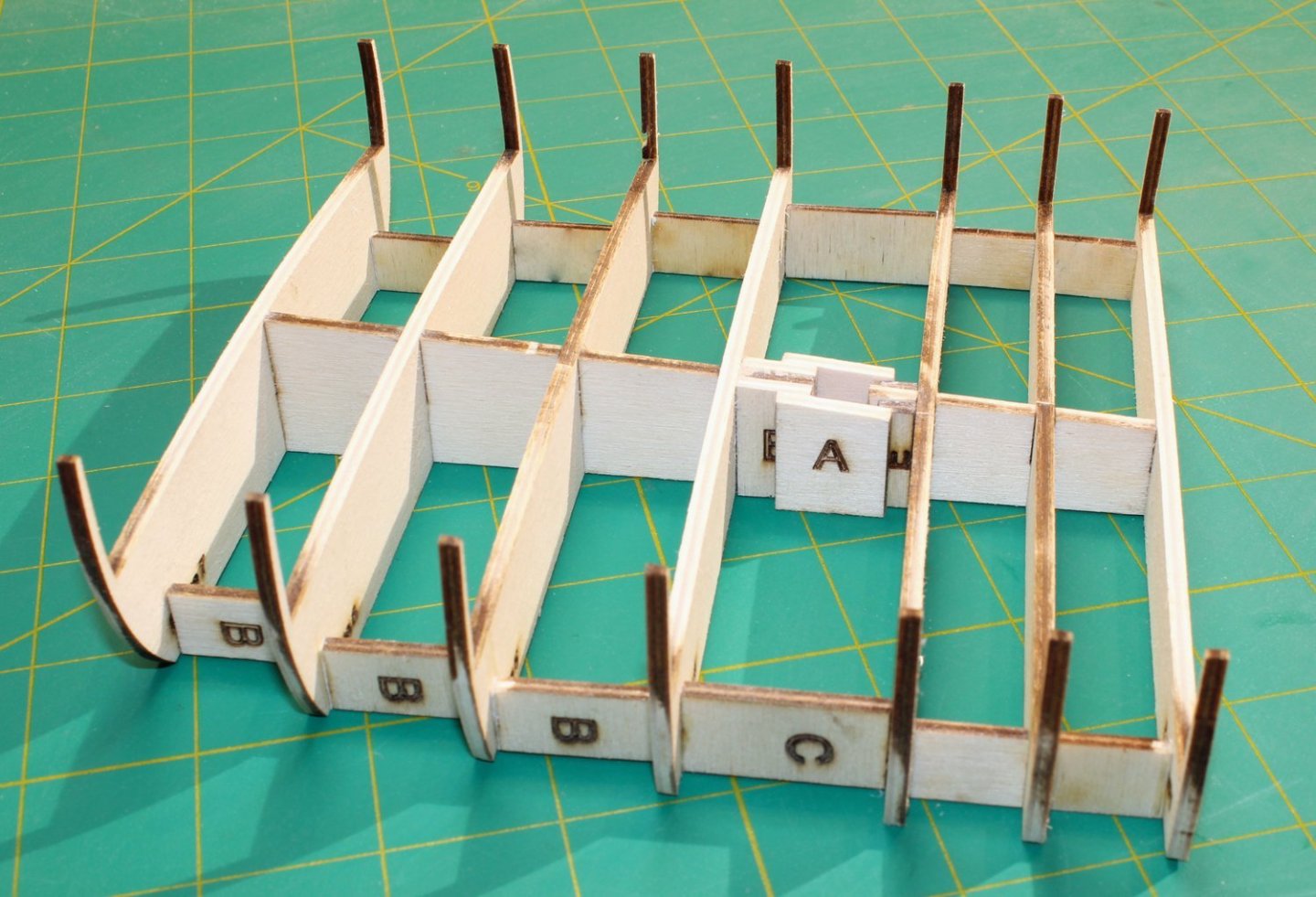
The NRG is an educational organization, dedicated to providing our members with the knowledge to improve the quality of their model ship building. One of the most common problems model builders have is rigging their model. Kit instructions are poor. Often, the materials provided in the kit are improperly sized or the cheapest that the manufacturer could obtain. We all know that blocks are not square! I wanted to develop a project whose purpose would be to teach ship modelers how to mast and rig a ship without having to build a complete hull. This model is a 1:48 scale cross-section at the level of the main mast of a late 18th century British sloop of war, Swallow 1779. To keep the size of the model manageable and eliminate the need for a building board, the hull is cut off just above the waterline. For the same reason, only the center portion of the lower yard and the lower part of the topmast are constructed. Also, because this is a cross-section, certain lines, such as the stays and backstays, are not included. My emphasis will be on demonstrating techniques to improve your rigging skills. Skills that can be used on your next project. As this was developed as a teaching aid, certain shortcuts and compromises to historical accuracy were taken. Wherever possible, I have used measurements provided by the plans and such authorities as Steel and Lees. I apologize in advance to the master modelers who might criticize my shortcuts. I have kept the use of power tools to a minimum. The only thing that is outside the normal collection of hand tools is a serving machine. The Guild hopes to begin selling this kit in the next few months. The kit contains all the materials required to complete the model. But I always keep my scrap box nearby for those times when a piece of a contrasting color wood is desirable. I will mention those times as the build log progresses. Also, the build log is made up from the best photographs taken from three builds of this model. A sharp eye will notice some differences in the wood color because of that. The hull is constructed in typical plank on bulkhead style. There is a notched spine and notched bulkheads. The laser cut sheet of one-eighth inch basswood ply also contains a template for the top and four types of spacers, A through D. The spine and the frames are assembled as seen below. Frame 1 is installed with the printing facing aft. This gave me the option of painting the exposed bulkhead after construction was completed. The mast fits in the slanted slot between Frames 3 and 4. To keep the mast vertical, support spacers are glued on both sides of the spine. They will be sanded flush to the spine when the hull is faired. To prevent the hull from twisting and to strengthen it, spacers are placed between each frame. The three aft spacers are “B”, the next one is “C” and the two foremost ones are “D”. They are placed close to the edge of the frame for maximum stability. The laser char only needs to be removed from the fore and aft sides so that their surfaces are flat. If too much wood is sanded off, I glue strips of paper onto the edge as a filler to prevent distorting the hull. The hull and deck were faired so there are smooth curves fore to aft. I used a sanding block for this. I did not fair the bulwark extensions (the thin strips of wood above the deck) to prevent them from breaking off. This model has a significant camber to the deck. Sanding sticks help getting into the corners. You can see that the mast supports have been sanded down to match the height of the deck. Next up is planking the hull.


- 30 replies
-
- 42
-
-
-
- rigging/masts
- NRG
- (and 1 more)
-
I hope you enjoy it, Mark. Last Fall I had a group of six modelers who I assisted with the kit, getting together for a half-day, every other week. It was a lot of fun for all of us.
- 4 replies
-
- 3
-
-
- half hull
- half hull planking project
- (and 1 more)
-
Everybody has their own preferred techniques. If I were designing this today, I know I would do certain things differently. We never stop learning and honing our skills.
-
ancre Le Gros Ventre by ChrisLBren - 1/36
tlevine replied to ChrisLBren's topic in - Build logs for subjects built 1751 - 1800
Sometimes we get lost between strict historical accuracy and common sense. You are showing the latter. A much smarter choice.