

tlevine
-
Posts
1,932 -
Joined
-
Last visited
Content Type
Profiles
Forums
Gallery
Events
Posts posted by tlevine
-
-
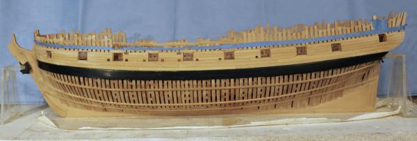
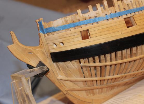
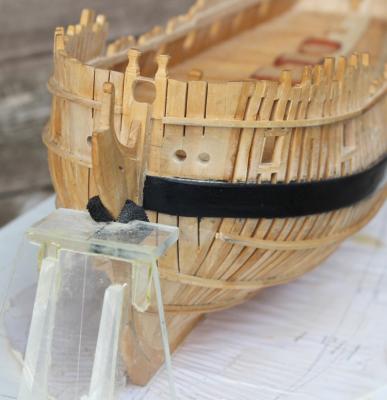
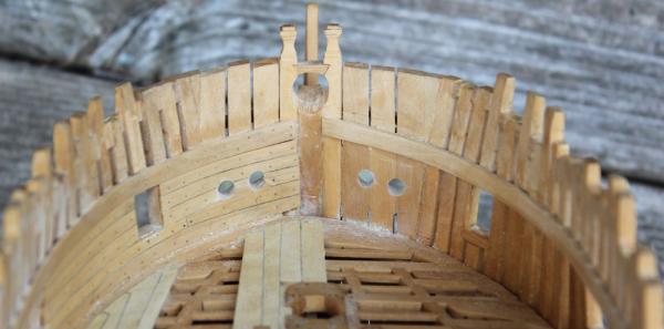
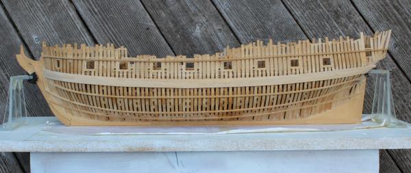
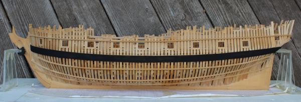
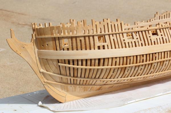
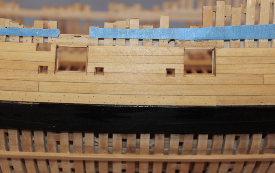
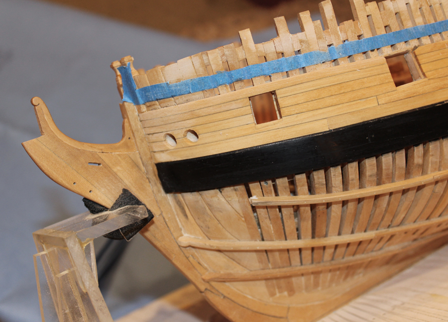
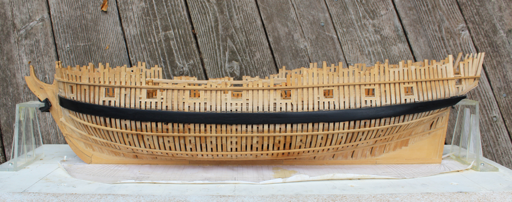
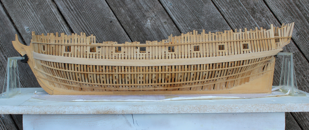
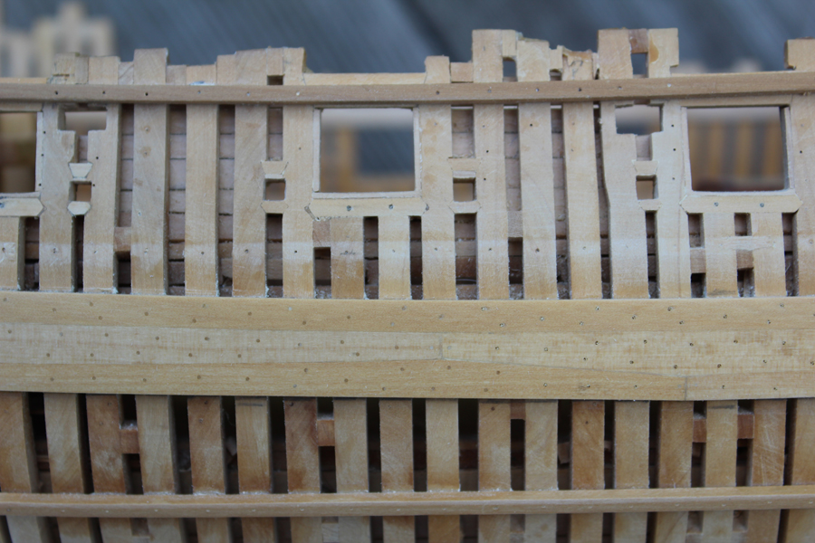
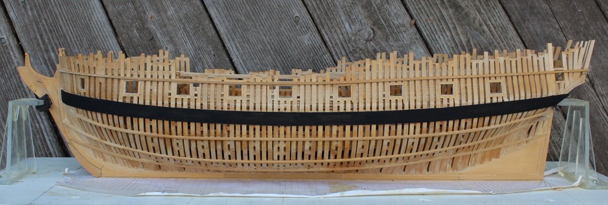
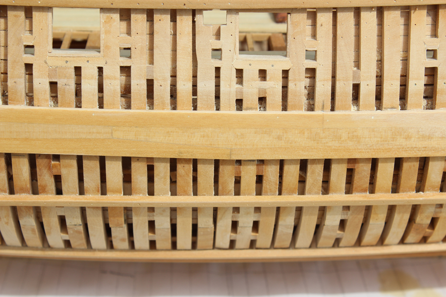
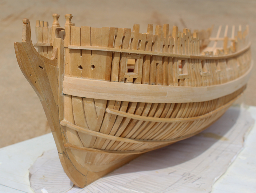
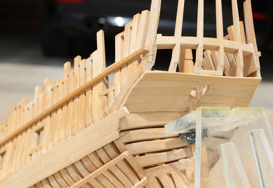
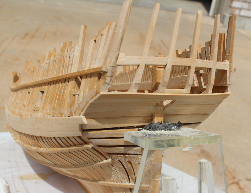
At long last the installation of the upper planking is progressing. After installing most of the planking up to the level of the top of the gun ports I discovered that the height of the lower sill was 2 scale inches too high. However, I also determined that the height of the bridal port and the last gun port were correct. To make everything perfect would have required removing all of the spirketing and the string in the waist. Well, that wasn't going to happen so I did the next best thing. I raised the sills of the bridal and aft gun ports one inch and lowered everything else one inch. There was minimal damage to the appearance inside the hull with this approach. In the first picture it looks like the aft port is too low. This is an optical illusion caused by the narrowing distance between the main wale and the bottom of the gun port as one moves aft. I removed the gun port liner after the outer planks were installed to get a better edge. The pictures show some of them reinstalled. I have tapered the thickness of the planking to 2 1/2". The sheer plank will be 3". I still have to finish sand the planks, reinstall the rest of the gun and sweep port liners and finish the opening for the sweep ports inside the hull. The scrapes in the main wale paint will be addressed when all of the hull planking is completed.

- harvey1847, Wishmaster, druxey and 15 others
-
 18
18
-
Martin, I think your problem is the final result of the situation you had with the fore plywood. I would suggest running a batten along the inferior and superior edges of the gun ports and mark out any necessary adjustments on the plywood sheeting. Then check the side walls of the ports for plumb. Your run of planking should provide enough structural strength that the gap between the plywood parts will not be a concern. Don't make any gun port adjustments on the plywood until you have installed a few rows of planking and don't put any planking butts adjacent to the junction of the plywood pieces.
-
Thank you Nils. Richard, the sills are the correct dimension but are positioned 2" too high. This affects the overall shape and width of the sheer strake but once everything is completed it should look ship shape. I have a suggestion for anyone installing planks above the wales. After the run of planking is marked on the frames, clamp a narrow spline just above the line so make sure you are happy with how the run looks overall. I found it difficult to keep everything aligned properly with all the fenestrations from the gun and oar ports. This helped me a lot when I replaced the planking.
- Mirabell61, druxey, dvm27 and 1 other
-
4
-
Thanks everyone for the encouragement. My biggest problem was that when I took the height of the lower sills of the gun ports off the NMM plans I did not realize that these were actually the height of the lined sills. Consequently, location of the gun ports are about 2" too high (the top of the gun port was measured off the port framing, not the plan so the actual size of the gun port is correct) and the run of planking had to be modified from the diagram shown in TFFM. I finally figured this out when most of the planking below the sheer had been installed and nothing looked right. After removing the planks I drew up a new planking diagram to compensate for the port height.
-
It has been a while since anything was posted but I have a good excuse. I had installed the black strake and most of the upper planking. When I returned the next day to finish the planking I decided that I did not like the looks of it and spent several hours of quality time with the isopropanol.
 I hope to have some pictures of the redone planking soon.
 -
Dan, pick up a 10-pack of each of your favorite sizes. Although I am sure the bits work better with a drill press, don't own one and have not problems using a battery operated Dremel or my Emesco dental engine. They do break if you bend them but I have also drilled hundreds of holes with a single bit if I am careful. I would not use the Dremel flex shaft as there is too much chatter in the handpiece.
-
-
Dan, I drill the first hole, shape the band by wrapping it around the mast, remove the band, solder and then drill the band and then install it over the masthead. Carbide bits are brittle but they are no more expensive than HSS and once you use them you will never go back. I would start with a #76 hole and enlarge it from there to your desired size.
-
What type of drill bit are you using? I have resharpened carbide bits from drillbitcity that work much better than the HSS bits commonly employed. I normally drill my first hole, then wrap the band around the mast. After it is soldered, it is easy to drill through the soft solder you are using and the first hole acts as a pilot hole for the other end of the mast band. If you are blackening the band remember that regular solder will not blacken. You need to use Staybrite or Tix.
-
Before you decide to leave the frames as is, please check the plans and make sure that this does not impact some other part of the hull, such as gun ports, scuppers, etc. Making new frames is much easier than getting everything else in line later.
- dgbot, flying_dutchman2, mtaylor and 1 other
-
4
-
If you are using actual surgical gloves (not medical examining gloves), the decrease in tactile feedback should be minimal. However, if you have a skin condition and you use powdered gloves you are opening yourself up to a whole new set of problems. The powder can sensitize your skin to the gloves themselves. Use only non-powdered gloves and rub your hands with a little mineral oil before donning them. Nitrile exam gloves, on the other hand, will reduce tactile feedback considerably but are hypoallergenic, unpowdered and extremely strong.
-
-
-
Looks very nice. I had some glue seepage on the interior but was able to remove it with scalpel blades and sanding sticks.
-
Thanks, Greg. I had a slight tear out on the inside port hawse hole so that will work out perfectly. I have a question... Are the openings parallel with the water line, tilt inboard or tilt outboard? I can see logical reasons for all three scenarios.
-
Thanks, David. Ben, it is about 1mm different. Sorry about switching to metric but in my line of work it is easier to visualize 1mm than 3/64". Greg, in David's book he stated that the holes were 10.5" and then talks about lining them later on. I assumed that the eventual diameter would be closer to 7-8". Am I wrong? I would prefer to have them at the correct final size before I start the upper works.
-
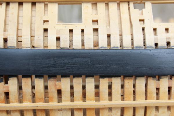
After six coats of paint I discovered that I did not camber the top of the wale sufficiently. There was also something about the finish that I did not like. So I sanded it all down and added the camber. I put on four coats of Model Master flat black enamel and sanded the last two coats with 1500 grit. This makes the plank seams and treenails a little more apparent and gives a luster to the wood without being shiny. Bolts at the butts were added after the picture was taken.

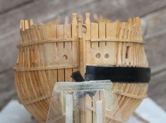
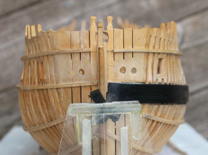
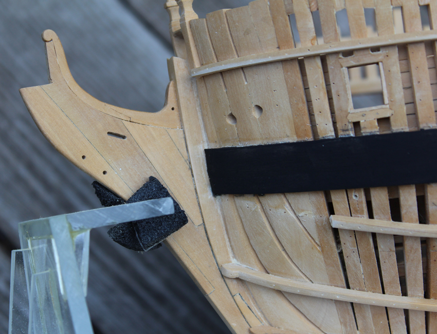
The hawse holes were left undersized until now. They are 10.5" in diameter. I used the top of the wale as the base to run a compass along marking the center of the holes. On the starboard side I used the ribband. The holes were enlarged with a combination of drill bits, Swiss files and sandpaper wrapped around a dowel.
-
Thanks Harvey and Remco. Ben, those were rough-in hawse holes. Greg noticed the same problem. Pictures to follow. Dave, the measurements are approx. 8" x 29". I do not plan on masting her.
- Trussben and SawdustDave
-
2
-
The planks of the main wale have been drilled for the bolts at the butts and the treenails have been installed. The bolts are 0.75" in diameter and the treenails are 1.25" in diameter. Although not quite to scale, I used a 77 bit for the bolts and a 75 for the treenails. I usually dry-fit the treenails, relying on the finish to hold them in place. However, I wanted some structural strength with these treenails so I drilled them deeper into the frames and dipped them in dilute glue to secure them. I realize no one will see them, but it only took a few hours and the added security is worth it. I wet the wale in the second photo to make the treenails stand out.

Next came applying a black finish to the wale. I tried several approaches before making my final decision. I found an unopened bottle of Floquil hull black. This looked good but when I applied the Watco's finish it rubbed right off. Next I tried archival marker. Looked good but the length of time it took to apply tried my patience. Feiberg's leather dye also looked good and allowed the joint lines to be slightly more apparent but it bleeds into the wood and I was afraid of getting it onto the stem (even with masking). My winning choice was artist acrylic paint. This comes in a tube and can be diluted to the desired consistency. It applies nicely and there was no concern about ruining the stem. I was a little sloppy in getting paint on the frames when painting the edges of the wale but this will be covered with planking and so will not show. The photos show the first coat applied. I am up to 3 coats and will probably go with 3 more. In between coats I am sanding with 600 grit wet/dry sandpaper (used dry). Each subsequent coat is more dilute than the initial one. I have left the aft edge a little long for final shaping later. The bolts will be installed after the painting is completed.

- Geoff Matson, Mirabell61, robin b and 22 others
-
25
-
Have fun with the cutter. As I recall, there was a problem with the top of the sheer. What are you going to use for the planking? We used holly at the seminar; it bends beautifully and is a nice contrast to the costello of the frame.
-
The three runs of planking that make up the main wale have been installed. As you can see, most of the joinery disappears after sanding. In the first picture I wet the wood to make the plank edges stand out. The next step will be to mark out and install the treenails. The slight rise at the fore end of the wale when looking head-on is not apparent when looking at the ship, so I am going to leave this be. I would cause far more damage if I tried to remove the wale in order to drop it 0.5 mm.


- SawdustDave, Jeronimo, WackoWolf and 19 others
-
22
-
Looking fantastic as always. The run of planking looks fine. The slight color differences between the planks help delineate them so they are not just a sea of costello. Enjoy your treenailing.
-
Yes, Druxey, I tapered the fore end of the plank down to 3" to fit into the rabbet. Greg, the joinery essentially disappeared after sanding, much less planking. But like so much of this exercise, I know it was down correctly.
-
Thanks Ben and John. Michael, I am first making a template of the plank on card stock and then transferring the shape onto the wood. I cut it out on the Preac and make final adjustments on the ship. As you can also see on the photos, I have removed the upper ribband and the for part of the second as well. The rest will be removed as the planking continues.


drying time for lime wood (Moved by moderator)
in Building, Framing, Planking and plating a ships hull and deck
Posted
After soaking, I typically leave the plank clamped to a former overnight to dry before gluing with PVA.