

tlevine
-
Posts
1,933 -
Joined
-
Last visited
Content Type
Profiles
Forums
Gallery
Events
Posts posted by tlevine
-
-
I also used brass rods for mounting. Both the rods and the "fancy" base came from Hobby Lobby. I did not taper them but I did drill a pilot hole in the keel assembly prior to press-fitting them in place. I then removed them until the model was completed. Keep in mind that the model weighs next to nothing so minimal strength is required for the mounting supports.
-
I used castello boxwood for my planking. My approach was different from the kit instructions in that I spiled the planks in a more prototypical manner rather than attempting to edge-bend them. I did not have to soak any of the planks. The castello is a pleasure to work with. It holds an edge and there are no fuzzies after sanding. I did not apply a sanding sealer...a must if you are using the enclosed basswood.
- Nirvana and fnkershner
-
 2
2
-
-
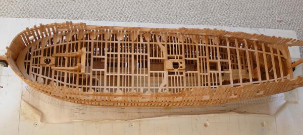
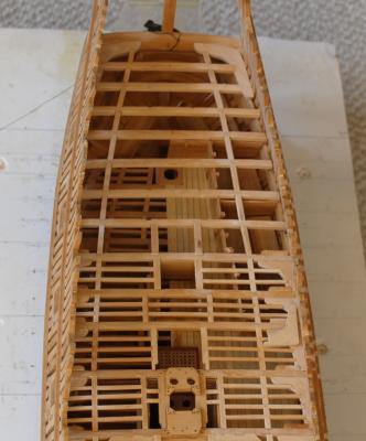
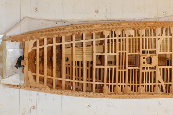
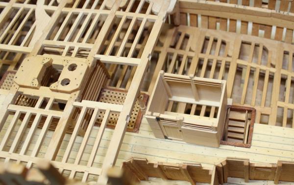
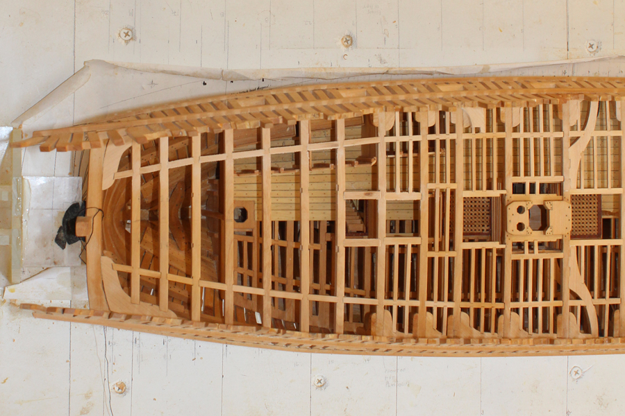
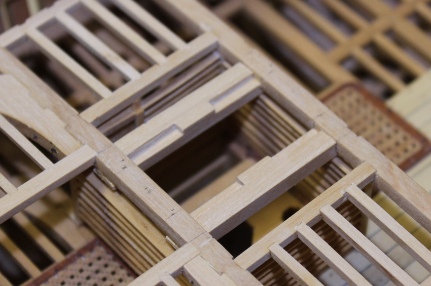
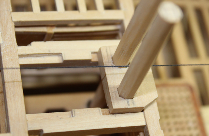
My general approach for fabricating and installing the beam sets has been one complete set at a time. This worked well where there was no curvature of the hull but I had difficulty with the run of the outer carlings at the fore end of the upper deck and decided to change my approach as I neared the stern. I set out all of the beams and tack glued them in place. I then drew fair lines for the outer carlings. The deck beams were removed as I worked on them, only mortising the outer carlings. The carlings were then tack glued without gluing the beam. This continued until the last two beams. The transom knee abuts the for end of the transom and extends along the hull just past beam 20. It is set down on to the deck clamp and "bolted" to the frames and transom. The last two beams are mortised into the transom knee.
The pictures show the run of the lateral carlings. No finish shaping or sanding has been done yet. I broke off the port counter timbers (again!) and just stuck it back on so that area looks out of whack. I will probably have to remake it when it comes time to make the counter.
- Dan Vadas, SailorGreg, WackoWolf and 19 others
-
22
-
That drawer set is fantastic. This is coming from someone who's Dremel, hand tools, sanding supplies, Optivisor, clamps, etc. all fit into a small tackle box to take with me when I travel to work.
-
Druxey, your post passed as I was responding to Remco. I'll go with low-tech.
-
You are absolutely right Remco. In fact, I have a tripod in my car trunk and on occasion I do use it. Just lazy I guess. Also, the dog has knocked the tripod over in the past (thank goodness the camera was not mounted on it at the time) and once I open it up I tend to leave it open the rest of the day. The dog is on vacation this weekend with the husband, so I will drag it out of car.
-
J.D., my cameral setup is anything but fancy. I use a Canon T3i camera fitted with the standard lens (18-55mm). I turn on all the lights in the kitchen, hold my breath so I can use shutter speeds of 1/60 and hope for the best. Sometimes I use the built-in flash but that normally gives me too much shadowing. Needless to say, I take 4-6 shots of the same thing and save the best one. A macro lens is on my "someday" list, along with a mill, a disc sander, a Jim-saw...
David, see you in a few months.
-
drillbitcity.com They are located somewhere in Chicago. An alternate would be any model railroad shop.
-
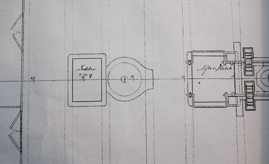
Now that makes sense to me, Druxey. When following a 300+ year old plan, it's difficult to pick the brain of the architect. Since there are many things on the plan that are not drawn in but simply assumed (carlings, knees, etc.) I thought this might be another one of those cases...a squarish step with a round base on top of it. Thank you.
-
As Chuck says, it is an optical illusion. Be careful not to make that aft line too much of a smiley-face. Once you install the rudder you will end up with a visual break in the curve. Looking good. Loved the kid's pictures in the Fiferail.
-
Thanks, Danny. I should have checked your build. It just seems so odd since the shape detracts from the strength and stability of the step.
-
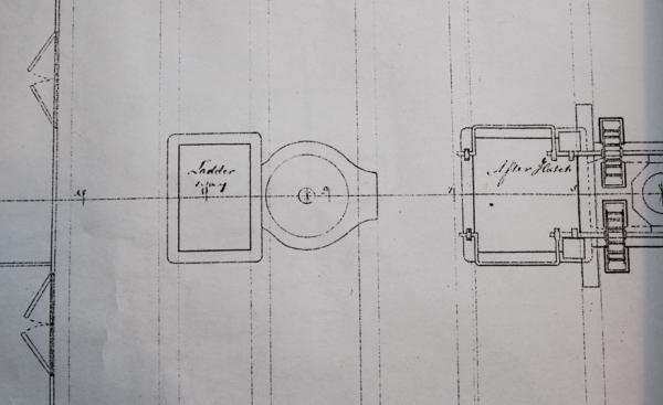
Work progresses slowly on the upper deck framing. No pics this week. The next significant structure to construct is the capstan step. In TFFM this is shown as a roughly rectangular block of wood inserted between the beams and its supporting carlings. On the Atalanta plans there is a ovate structure instead. This would seem to have much less strength than the one suggested by David. I am looking for some help on this one. Is the structure shown on the plan correct? Or is this seated on top of a rectangular step?
- Elmer Cornish, WackoWolf and Kevin
-
3
-
-
Thank you everybody. JD, I spend 8-10 hours a week in the workshop (aka kitchen counter). Please remember that the first sawdust was made in July, 2011. I figure that I am on the 5 year plan... and that is without masting her!
-
Wow! Not only is the craftsmanship great, but the tutorial breaking it down step-by-step is even better (if that's possible).
-
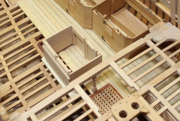
John and Elia, thank you for your kind comments. Thanks for all the Likes as well. A little more has been accomplished this weekend. I have applied the finish to the pantry. Beam set 14 has been installed and beam set 15 is in progess. The middle carlings are larger to support the capstain partner. Unlike the carlings for the mast partners, this piece is installed like a regular carling (ie from on top) rather than under the beam.


-
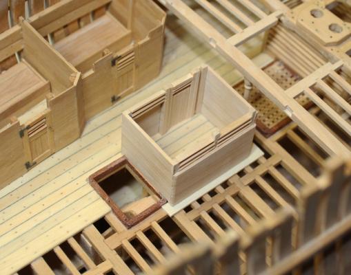
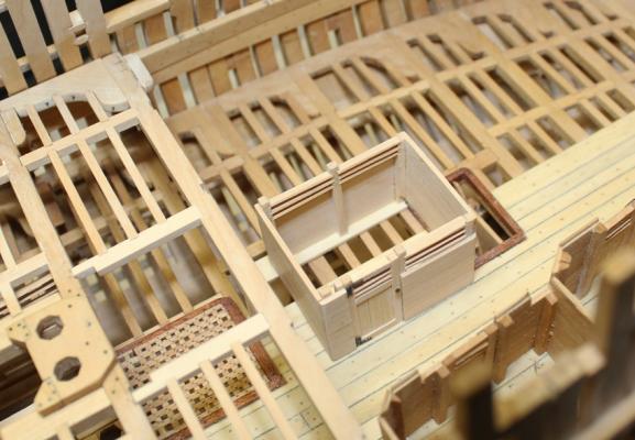
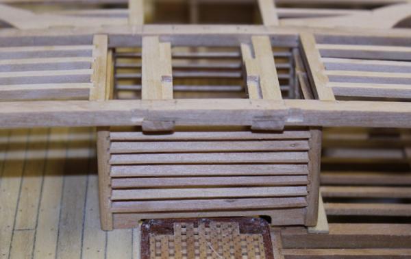
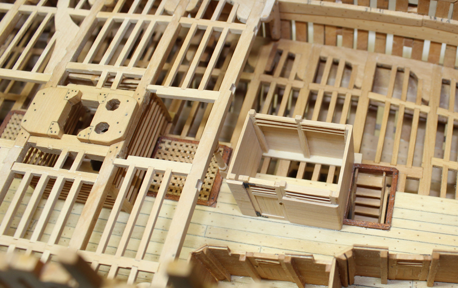
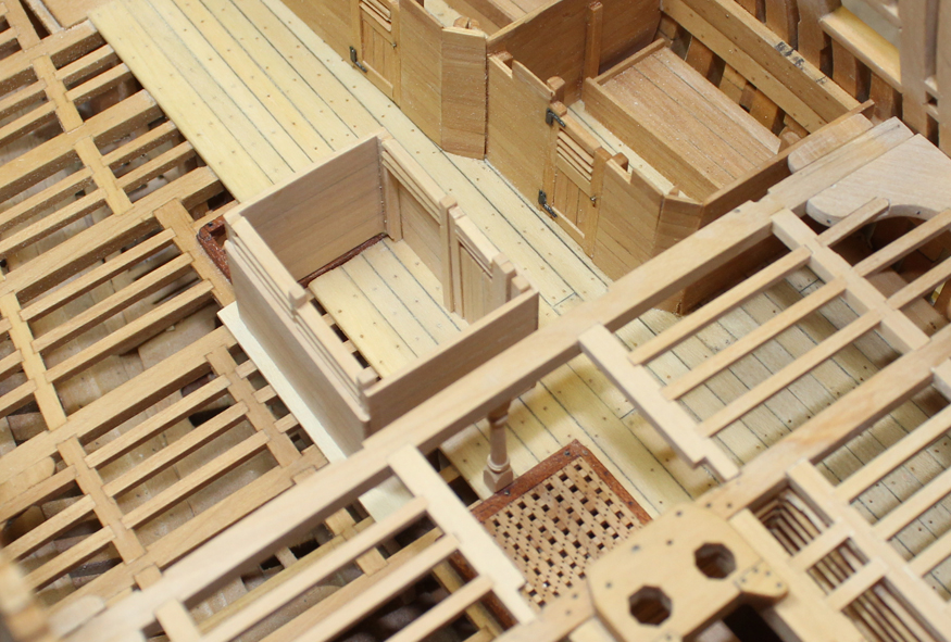
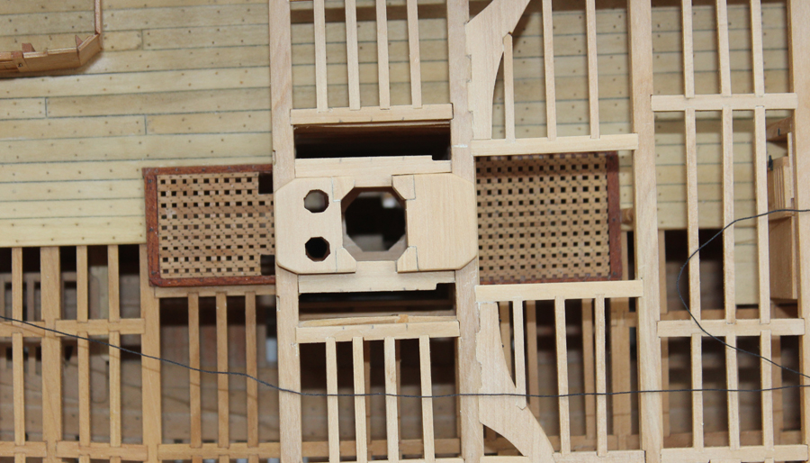
The pantry is located on the lower deck in front of the ladderway. It is constructed with partially louvered walls like the sail room. In contrast to the sail room, there is a standard swinging door rather than a slider. I finally tried to cut the slat mortises on the table saw. I had to free-hand their locations as I could not quickly develop a jig. A piece of 1 x 1 mm brass clamped down to the saw table would have done the trick but I did not have any and when I tried to cut wood this dimension it disintigrated. I think they came out reasonably well. Next time I would run out to the model railroad store a few towns away and buy the brass square as the mortises look better even though once the slats are inserted there is really no difference in appearance.
The plan shows the door underneath the beam (not installed on these pictures). I found this odd because this would limit the door height and also because a support stanchion could be incorporated into the door frame if the door was located between frames. I built the door in the location shown on the plan. I also decided not to put a pillar under beam 13 as this would end up in the middle of the pantry and restrict the storage possibilities. A stanchion on the starboard wall will be the substitute for the pillar.
- Elia, mtaylor, Wintergreen and 14 others
-
17
-
Dan, just be sure to play around with that airbrush off the model first. BTW, my paint was applied with a brush. When it came to applying paint near the masking tape, make sure that the brush is almost dry and paint from the tape down to the wood. As soon as the paint is dry-ish get the tape off so it does not tear out the paint. If you have to apply a second coat (I did) stay away from that nice crisp line by masking over it with the blue painters tape. Don't burnish it and get it off as soon as the second coat is applied. You'll do just fine.
-
Your talent is unbelievable. What are your going to cook on that stove first?
-
-
Christian, Ben and Druxey thank you. And thank you, everybody, for the "Likes". David, I use different chisels depending on the job. For the mast partners I used a 10 mm Two Cherry and a 1/8" Stanley Sweetheart chisel. On the smaller mortises I use a 3 mm Dockyard chisel. Mark, this was definitely a case of 1mm here and there making a huge difference in the pump tube alignment. Luckily, the repair is barely noticable.
-
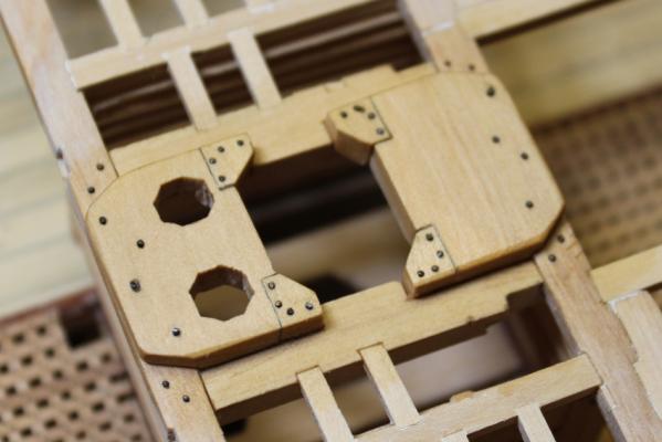
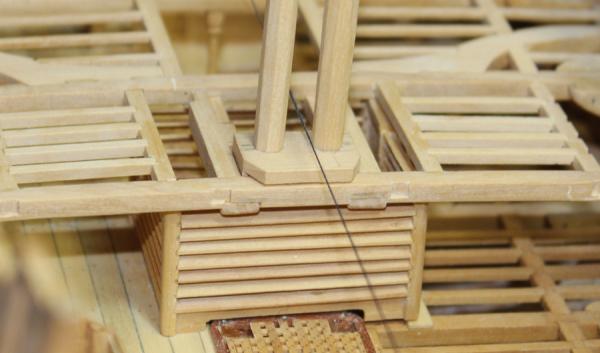
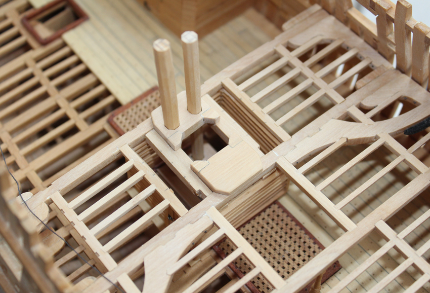
The chocks were fitted next. The edges were highlighted with pencil to make the seams stand out.
The assemblies were then glued in place. The aft partner was glued using the log pumps to help alignment.
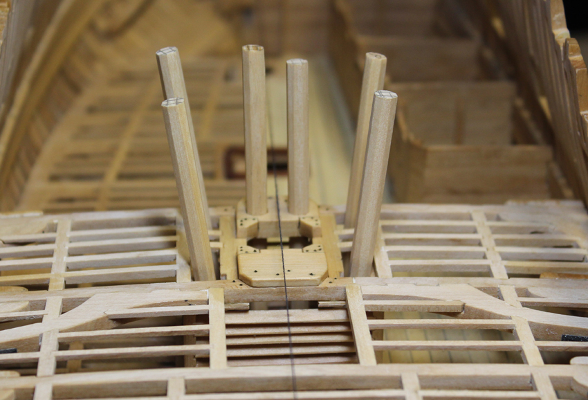
After the glue was dry, I cut the mortises for the ledges between the partners carlings and the middle carlings. Because of the locations of the pumps and the main topsail sheet bitts, only two ledges would fit. The multiple bolts were added and a coat of finish was applied to seal the bolts in place. I typically dry-fit the bolts, only using glue if the hole is too large. The last photo shows how it will look with all six pumps in position.

-
Thanks everyone for the "Likes".
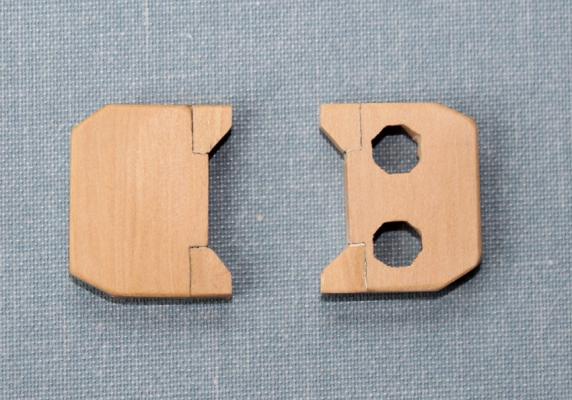
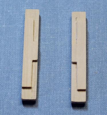
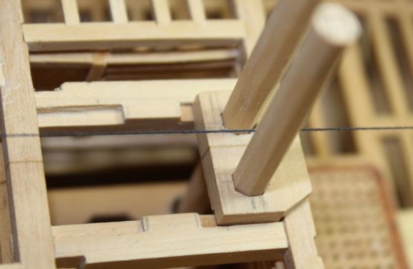
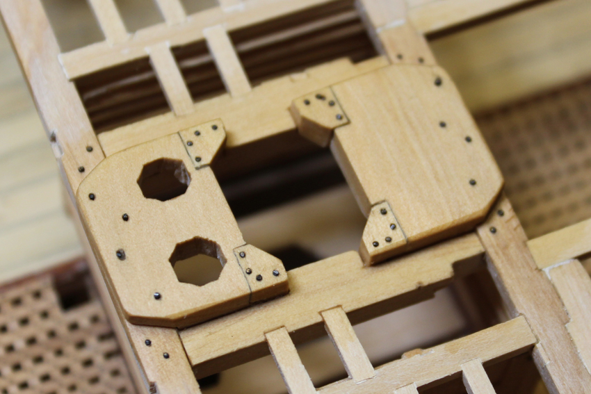
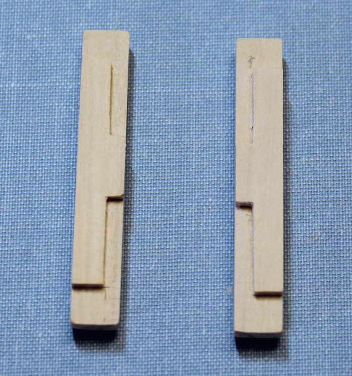
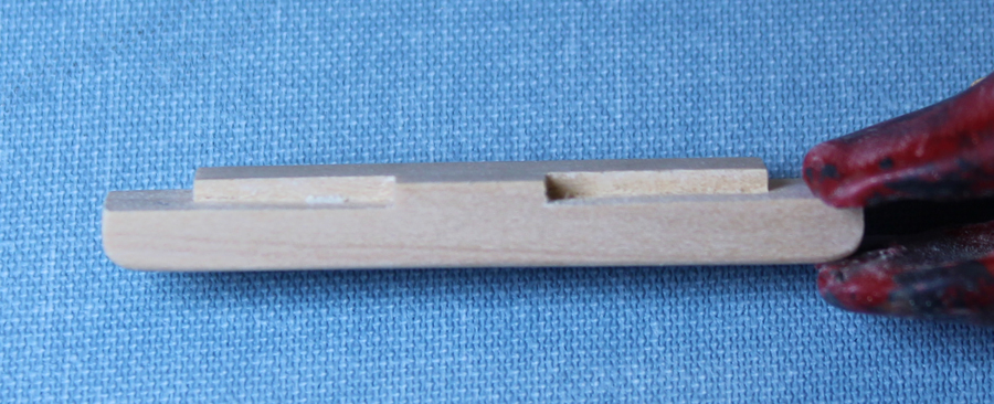
My next project is beam set 12, which includes the main mast partners. The beam set itself is straight-forward. The main mast partners is similar to the fore mast partners...only larger. The carlings are half- mortised into beams 11 and 12. I had previously made the decision not to cut the mortises on beam 11 ahead of time because any mistakes would be very obvious. My intention was to cut them in once I had the mortises cut on beam 12 so they would be exactly parallel. I could not cut them to my satisfaction because the upper well was in the way of the chisel. I did not wish to remove the upper well and possibly damage it so I faked the fore tenon. In the pictures you can see the recess cut into the carlings for the partners as well as the difference in the thickness of the fore and aft tenons.
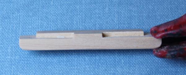
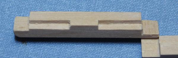
The next pictures show the fore and aft ends of the carlings after they were installed and before final sanding.

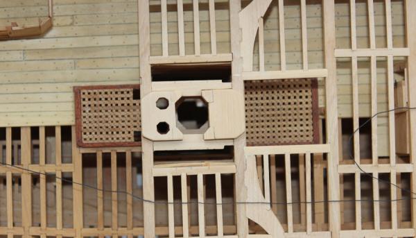
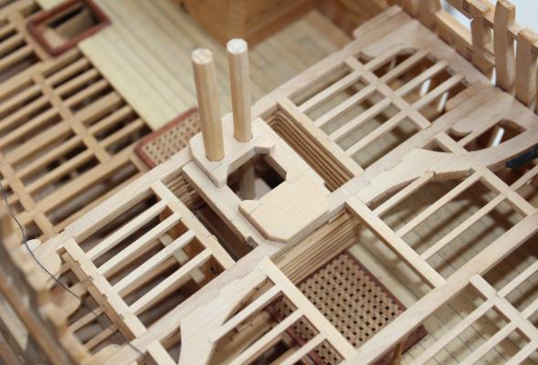
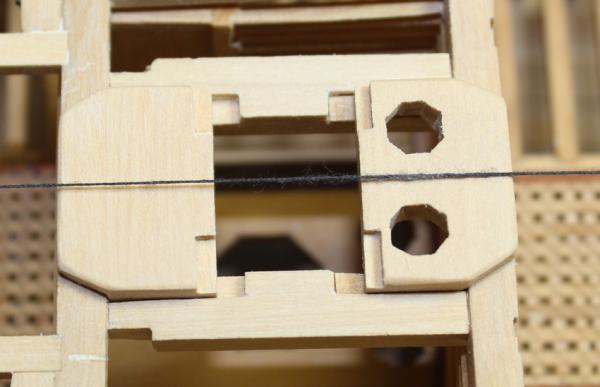
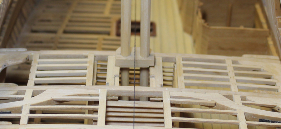
The aft partner was addressed next. This has octagonal holes cut into it for the pumps. Now comes the tricky part. These log pumps extend through the previously cut holes in the lower deck main mast partner and insert into the pump intake lateral to the keel. They also need to be perpendicular to the keel and slightly canted away from each other. The holes in the lower deck partner needed to be "adjusted" to accommodate this three dimensional arrangement. That's a euphemism for totally trashing the holes. After the aft partner was temporarily glued in place, I inserted the logs down to the hold. I made a veneer of boxwood and planked over the lower deck partners to disguise the error. In the third photo you can see the widened hole in the lower deck partner before the repair. The fore partner was made and the last picture shows it in place.

- Elmer Cornish, WackoWolf, druxey and 8 others
-
11


HMS Atalanta by tlevine - FINISHED - 1775 - 1:48 scale - from TFFM plans
in - Build logs for subjects built 1751 - 1800
Posted
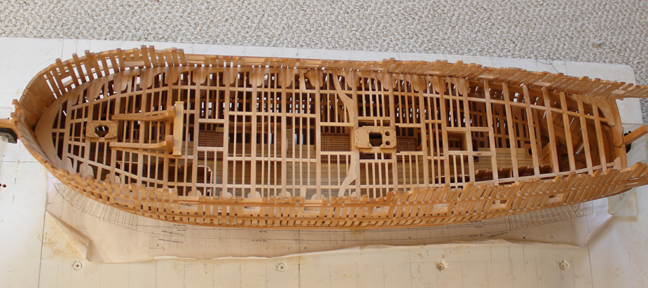
It has been a few weeks since the last update. Not that much has been accomplished because of that four letter word...work. I have all of the carlings temporarily installed, as well as the ledges between the carlings. I am still adjusting the height of the last two deck beams. The transom knee was made overly thick and now the top of the beams is lower than the top of the knee. The knee will be sanded down once I am happy with the fair run of the deck. Beam set 16 is completed. Only six more beams to go! The bracing across the outer counter timbers has been removed for the pictures. I decided not to build any more structures that stand proud of the deck until the deck is completed and sanded fair. The main mast partner kept getting bumped when I was truing the middle part of the deck. This should make sanding easier.