

tlevine
-
Posts
1,930 -
Joined
-
Last visited
Content Type
Profiles
Forums
Gallery
Events
Posts posted by tlevine
-
-
-
-
Thank you everyone. I will locate the guns at chest height. The top of the mounts is at 3 feet above deck. Unfortunately, that will entail some serious surgery to the already-built mounts.
- mtaylor, Chuck Seiler, dvm27 and 1 other
-
 4
4
-
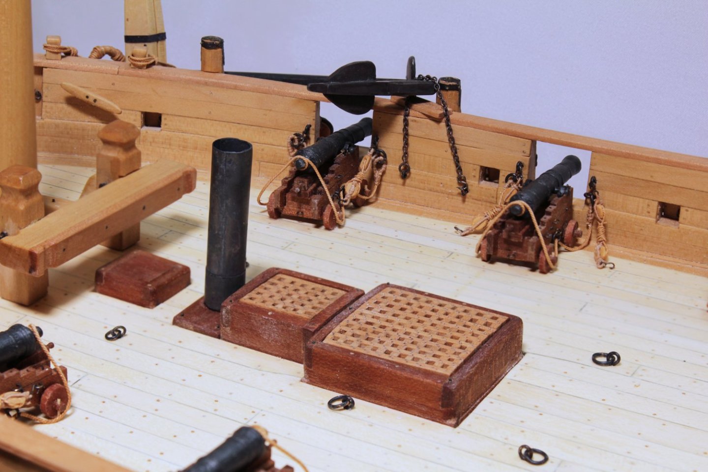
I am getting ready to install the swivel guns I made last year. They look too tall to be used comfortably. Does anyone know what elevation the muzzle should be from the deck when it is horizontal? I am guessing eye level but would hate to install them and then find out I guessed wrong.
-
Thanks, gentlemen. Unfortunately, without knowing the height of the rails and swivel post, it is difficult to determine their elevation from photos.
- Chuck Seiler and mtaylor
-
2
-
-
What would be the height for a swivel gun above the deck? Waist? Chest? Eye level?
- Chuck Seiler, mtaylor and bruce d
-
3
-
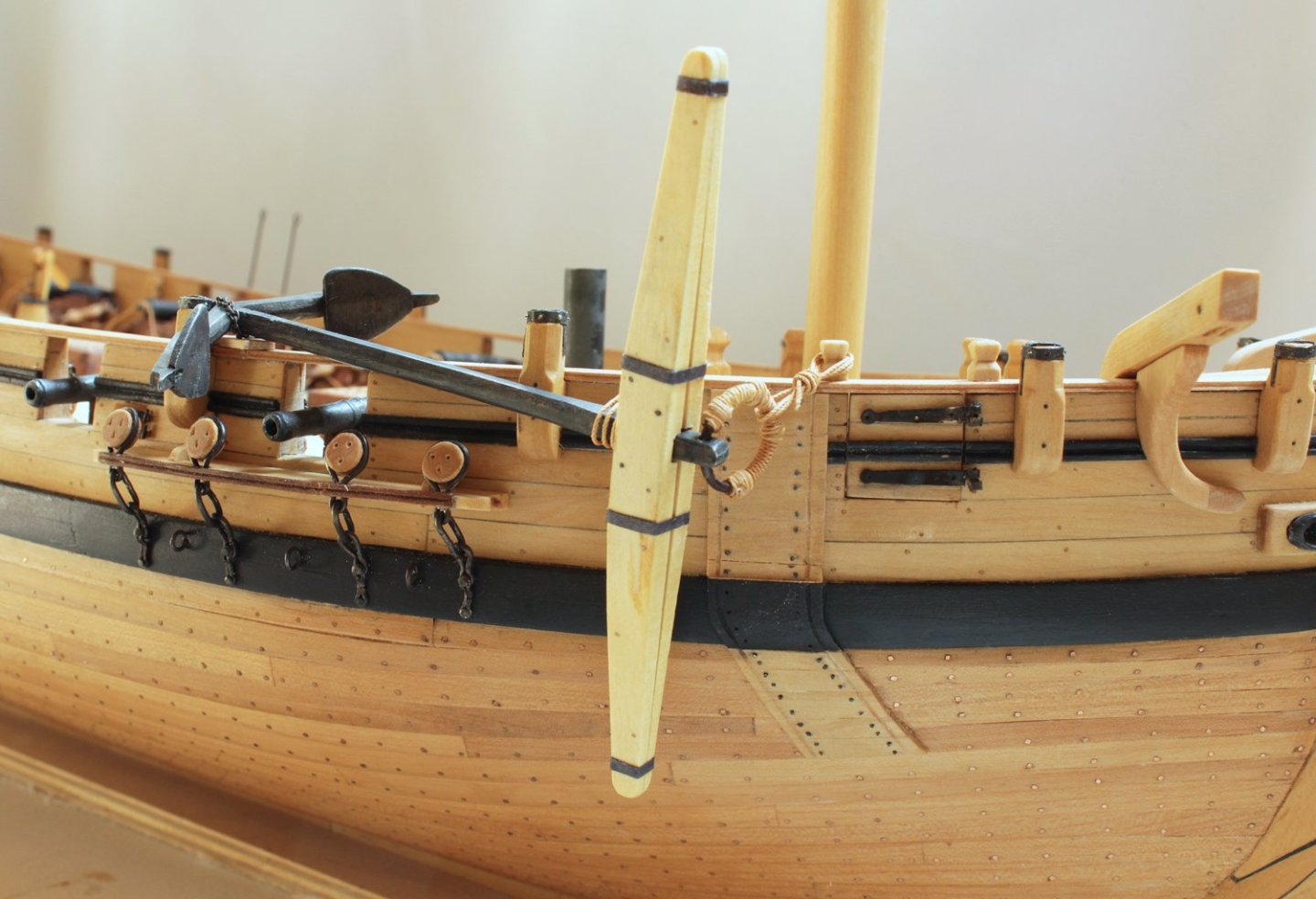
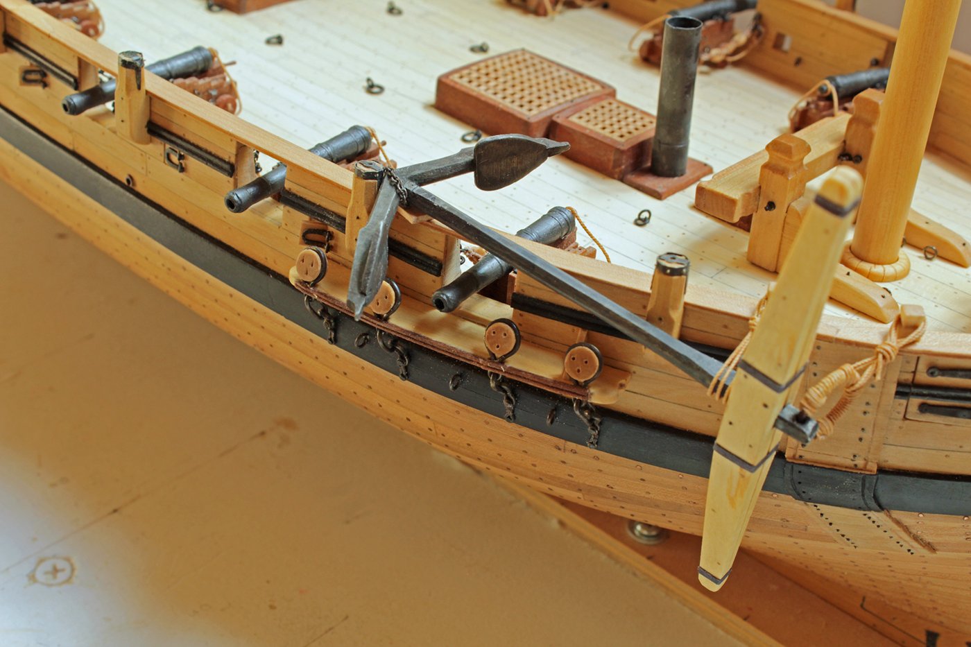
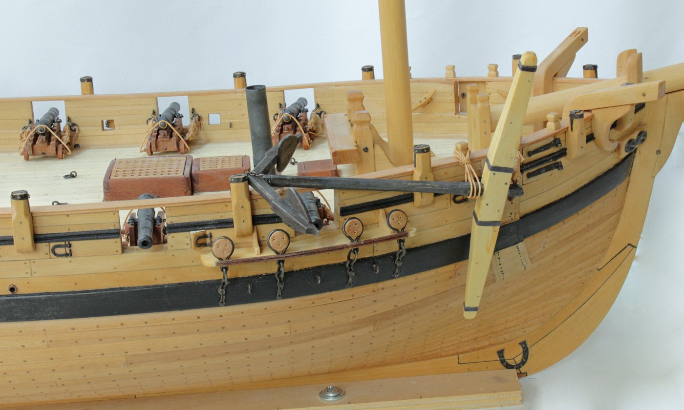
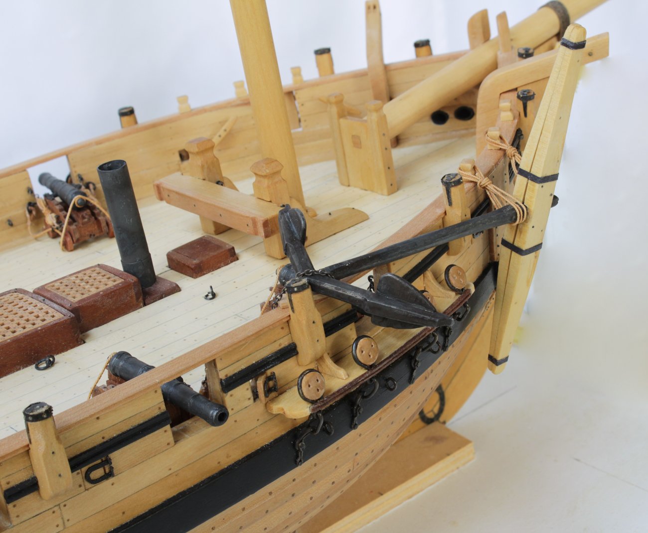
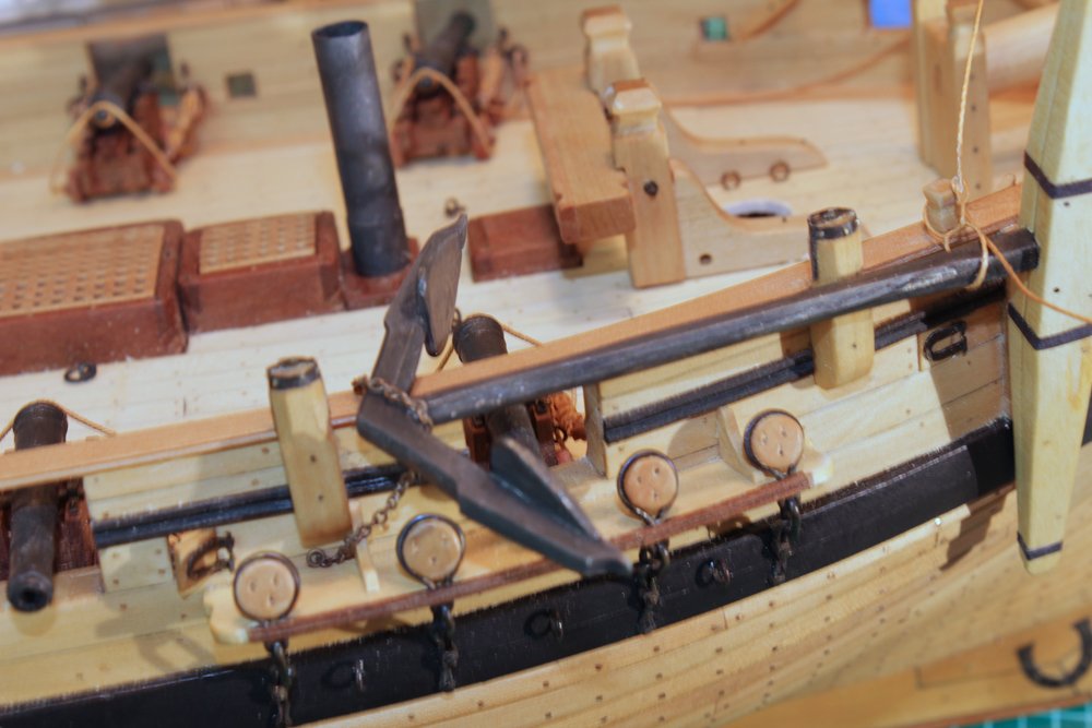
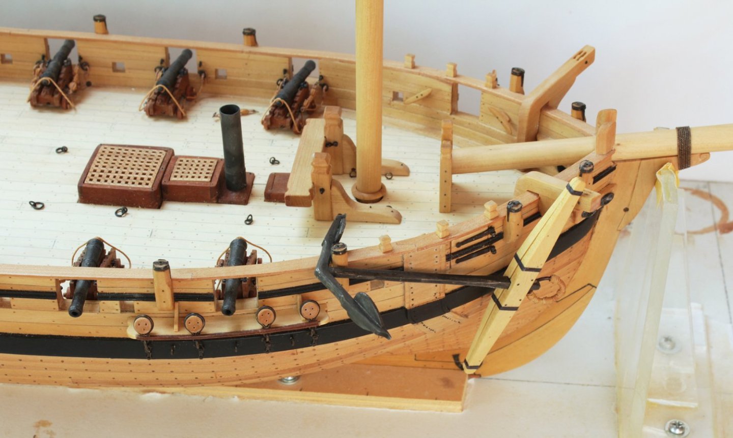
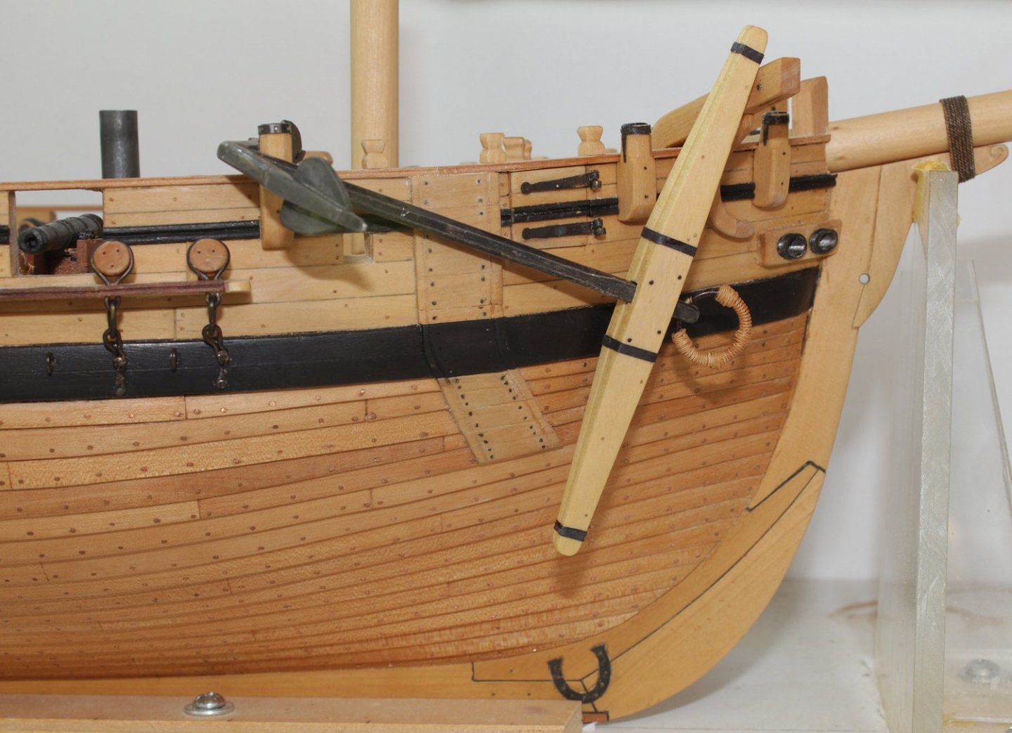
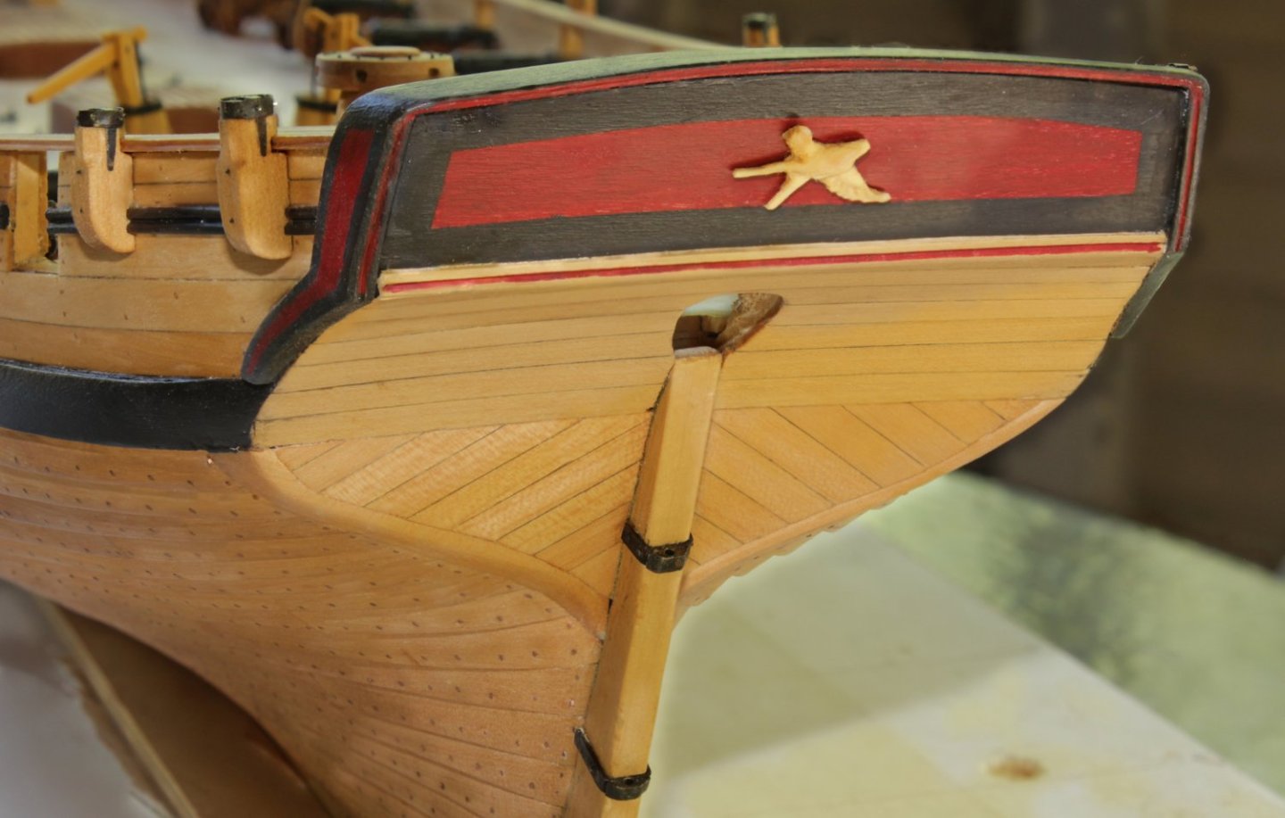
After looking at other models for ships this size, I decided to secure the lower shank with the shank painter. As druxey suggested, one end is attached to a ringbolt inside the bulwark and the free end terminates in a hook which is secured in a second ringbolt. The upper part of the shaft and the ring were tied off to timberheads. I have added a block of wood on the rail under the anchor to protect the rail from damage.
-
-
How does this look? The shankpainter would be bolted to the hull and drawn up over the bottom of the anchor shank and secured to a cleat on the inside bulwark. The top of the shank would be secured to a timberhead.
- KenW, CiscoH, Seventynet and 10 others
-
13
-
-
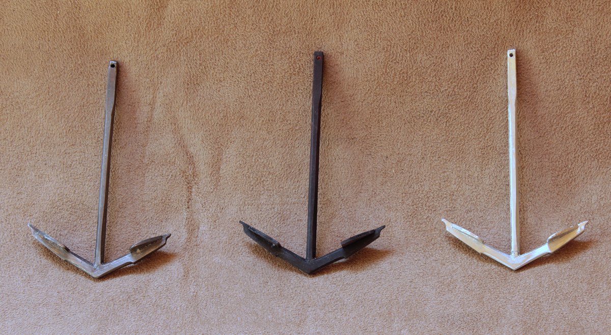
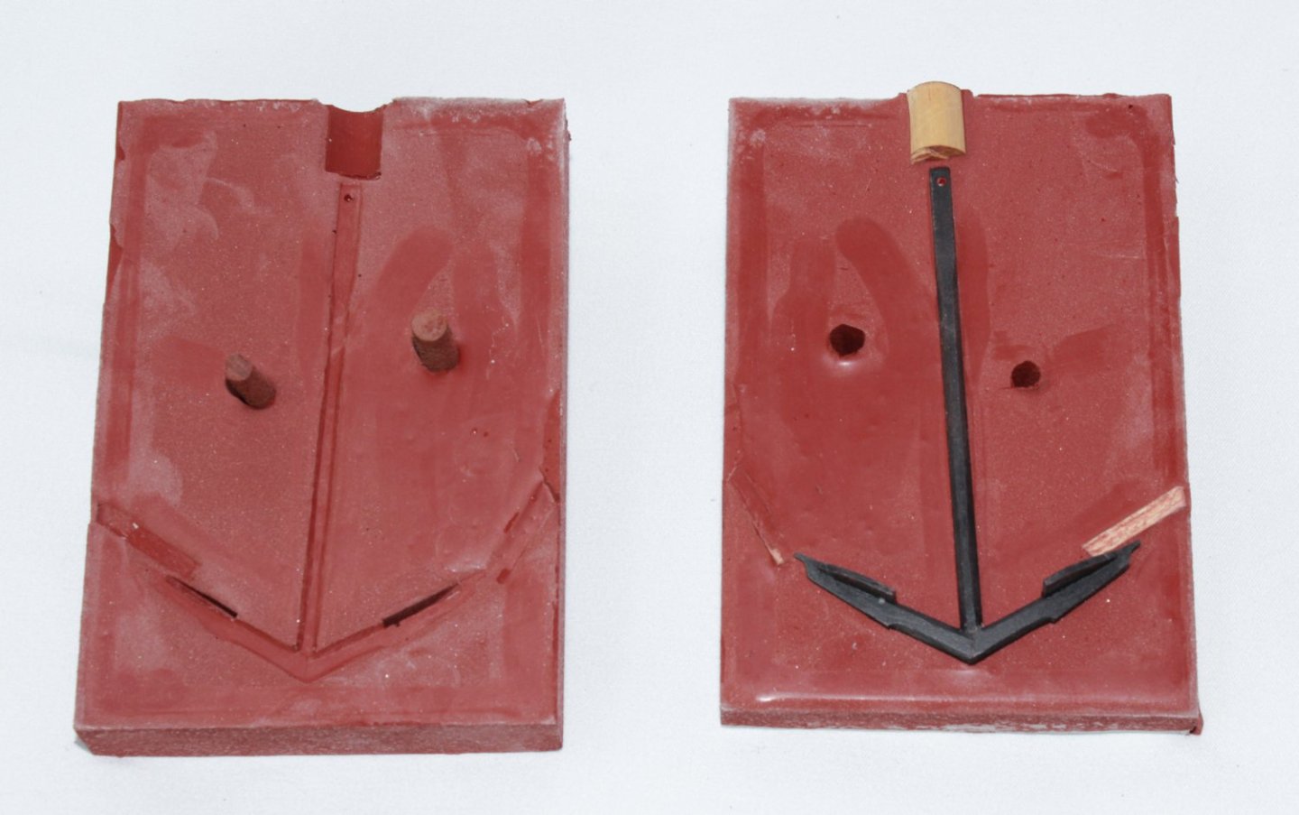
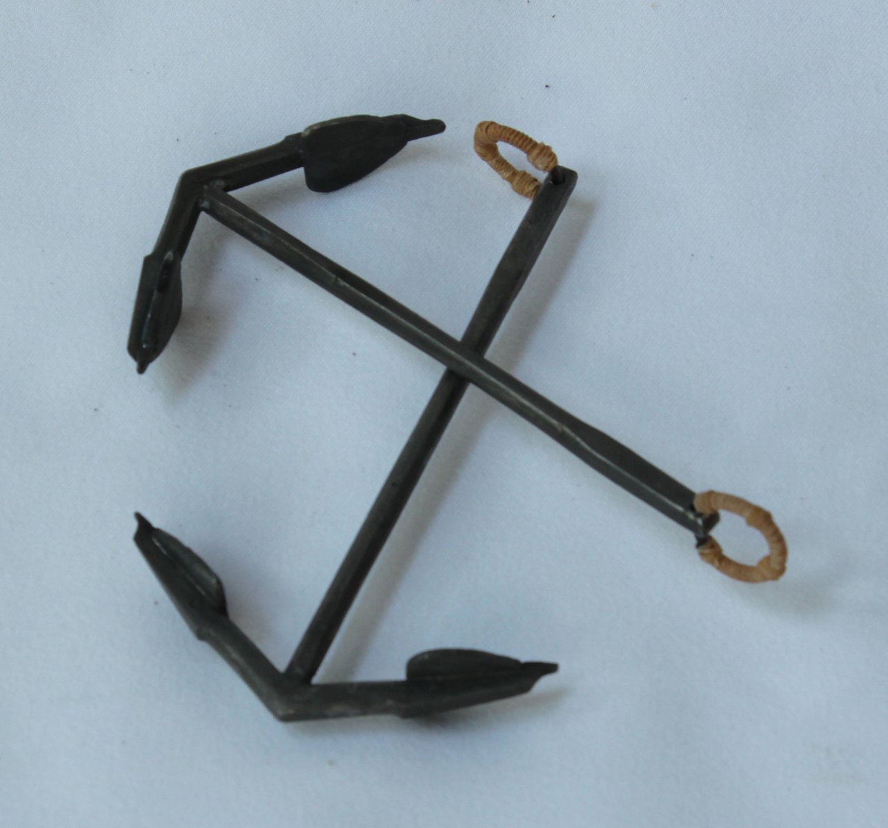
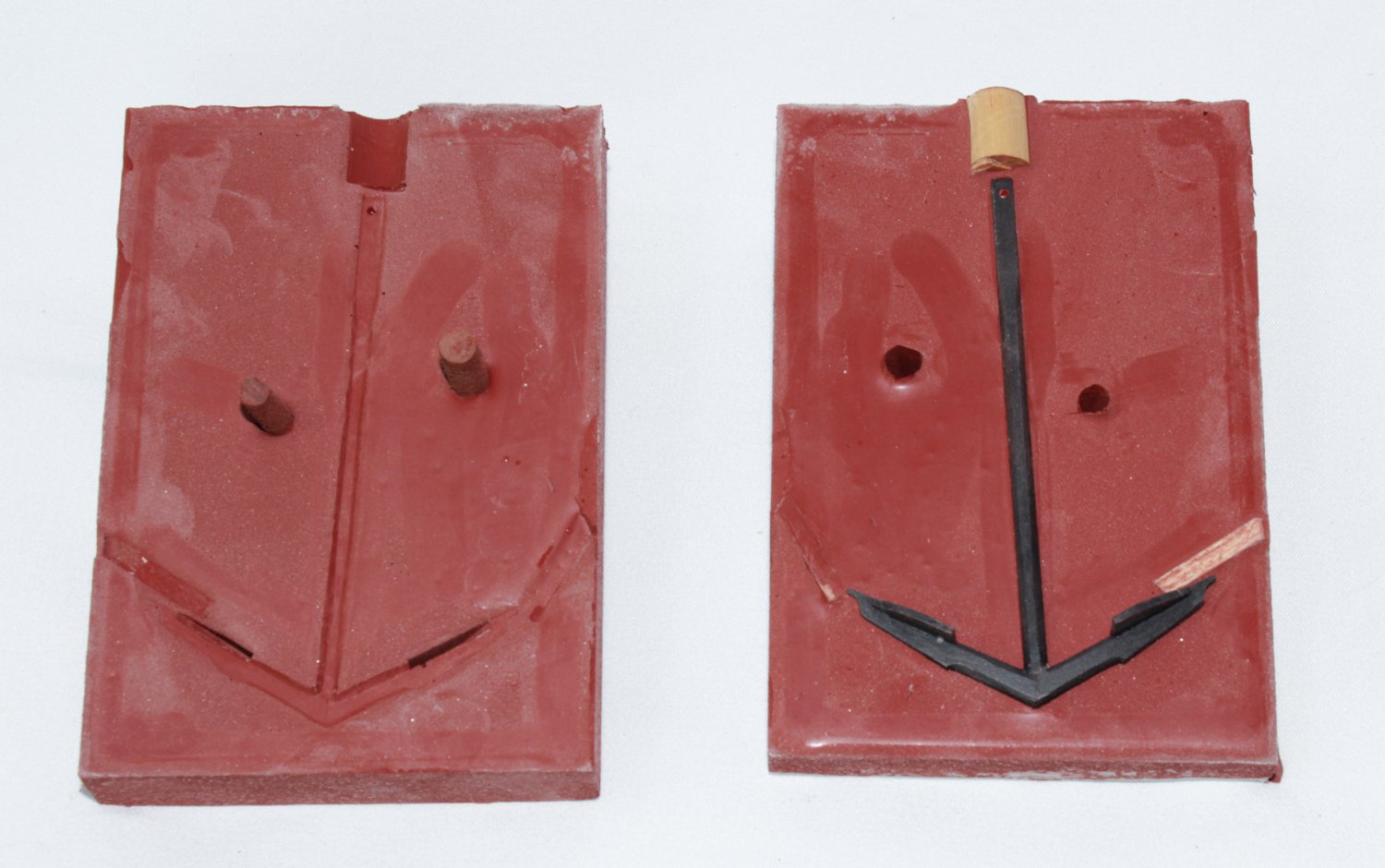
This is how it looks with the upper mold removed and then out of the mold.
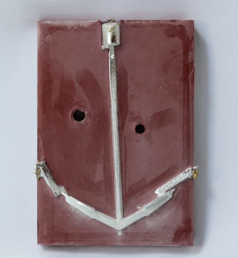
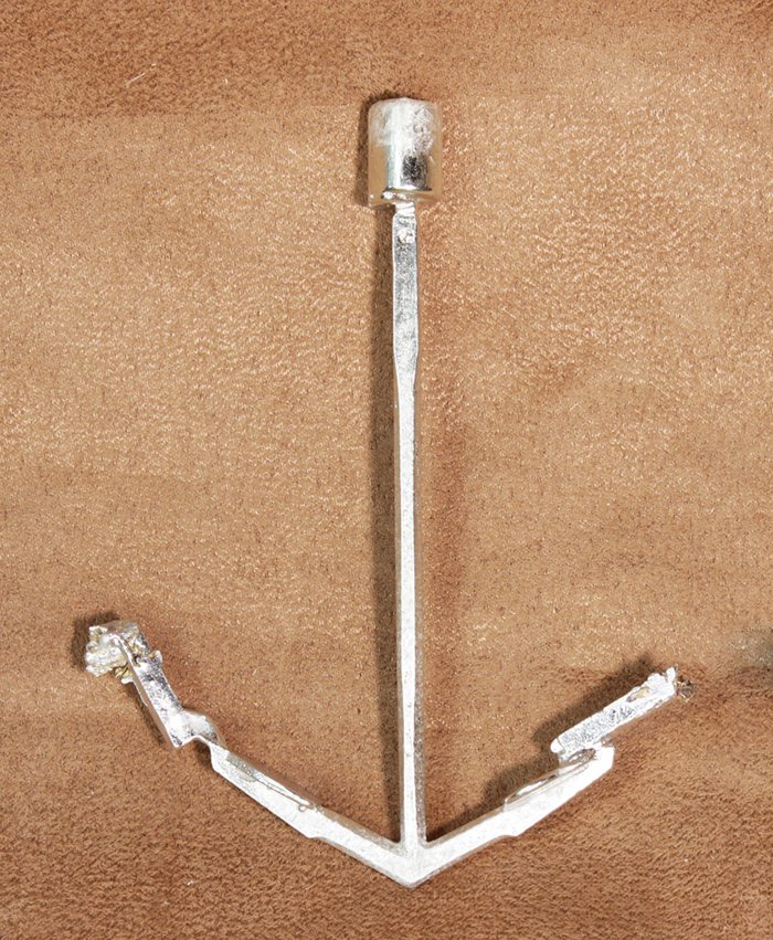
In the middle is the master anchor, to the right is the cast anchor after polishing and to the left is the anchor after taking a bath in Blue Jacket's Pewter Black.
I applied the seizing and puddening to the anchor ring and then installed them on the anchors.

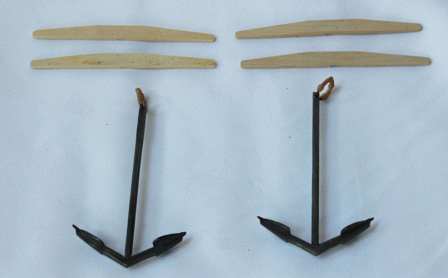
The anchor stock was made next. You can see the holes drilled for the bolts and treenails.

The stock was then applied to the anchor and the "iron" rings were applied. These are actually made from paper. Overall, I am pleased with the result.
As I mentioned previously, I want to show the starboard anchor lashed to the hull. As the ship's base will be a launching ways, the hawser cable would not be attached. These pictures show the only location for the anchor that does not block any of the ports. I have been looking in all the books I have, as well as looking at models on the RMG site, and cannot figure out how it should be secured. I presume the shaft would be lashed to the aft timberhead but there must be some other rope securing it. Any advise would be greatly appreciated.
-
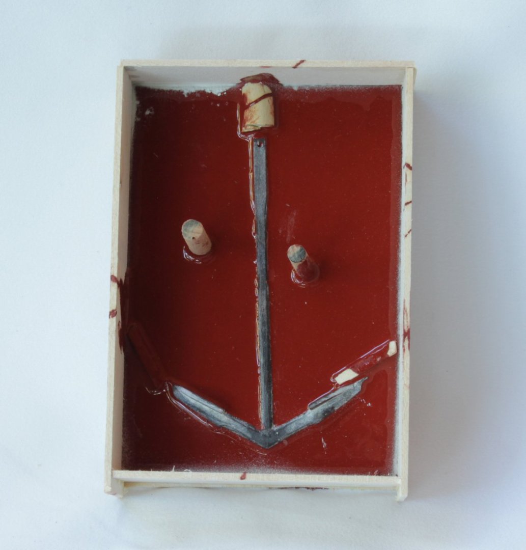
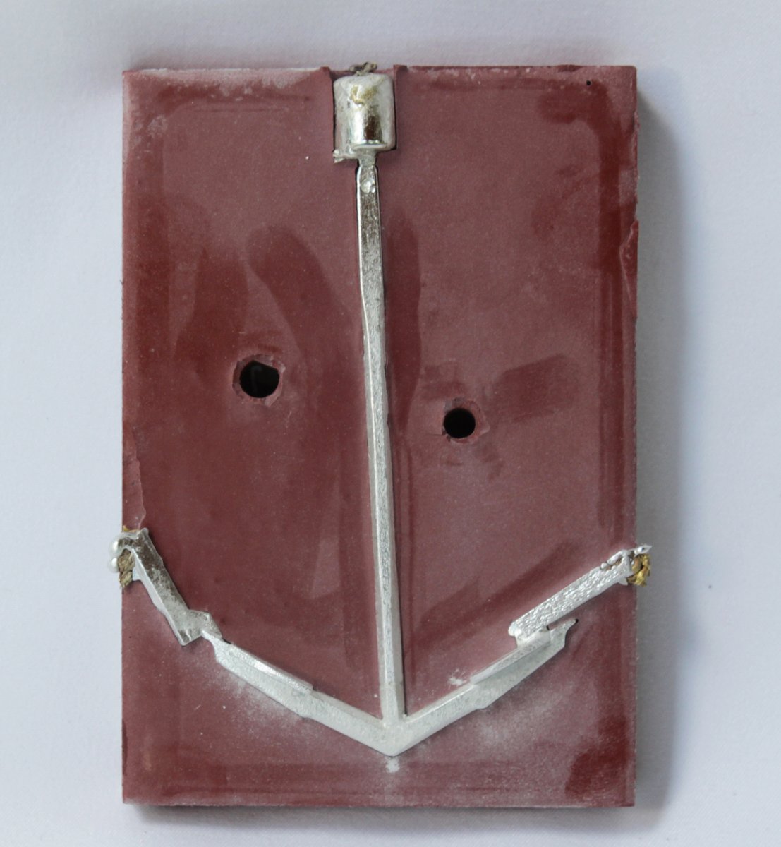
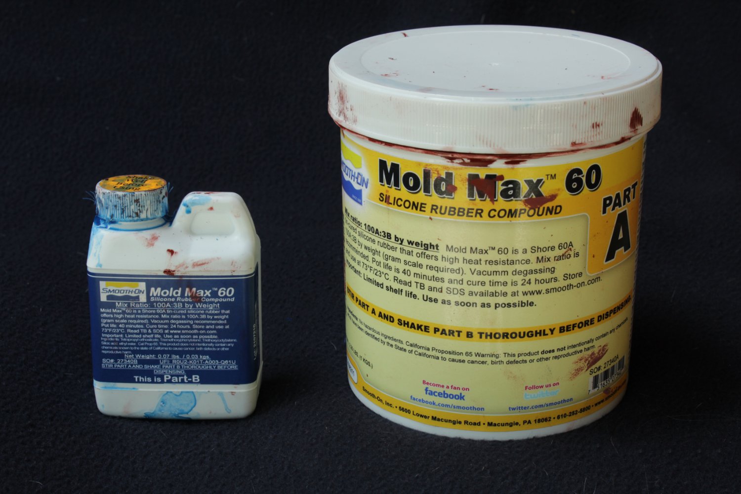
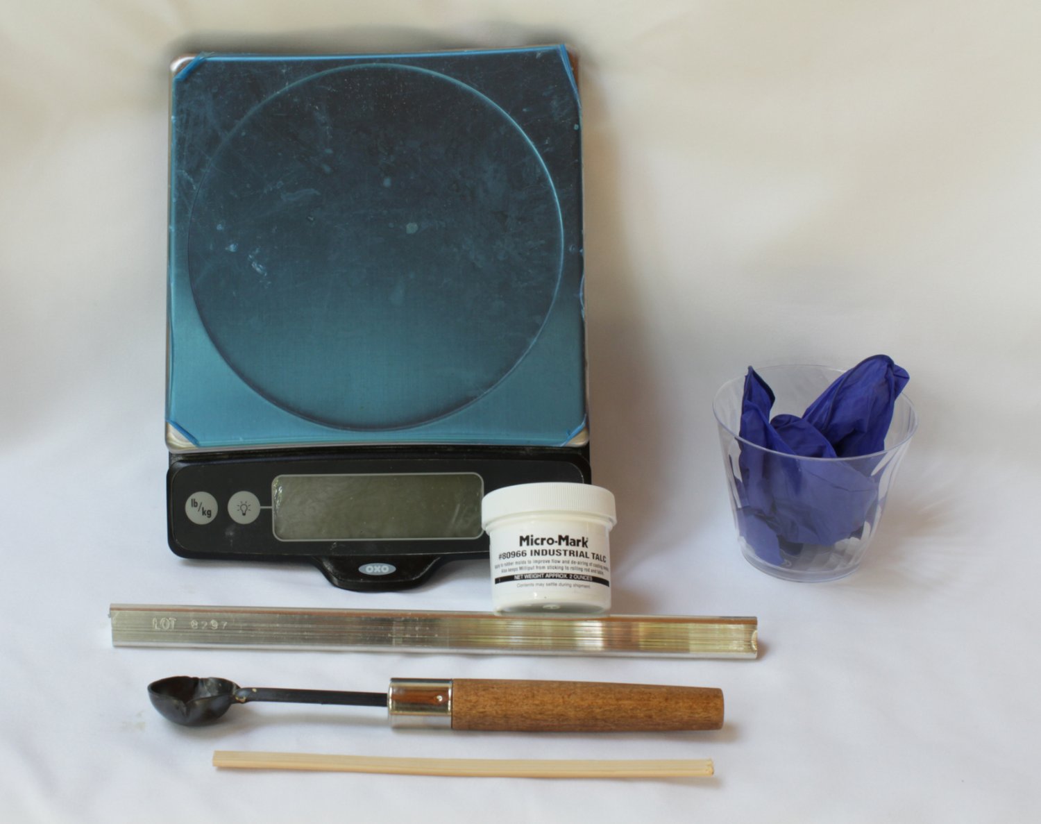
Thanks for looking in, Dan. As for rigging, the only other rigging I plan on doing is for the anchor! Speaking of which, I will be showing the ship with two bower anchors; the starboard one will be secured to the ship and the port will be lowered onto the base. Since I had good luck casting the armament, I decided to cast these from pewter as well. This is the material I use for the casting. It is a high temperature silicone rubber that can be used for low-melting-point metals like pewter. The second picture shows the rest of the equipment necessary for the casting, including a pewter rod. As you can see, there is nothing exotic about the process. It is, however, very sensitive to the relative weights of the components, so they need to be weighed down to the gram.


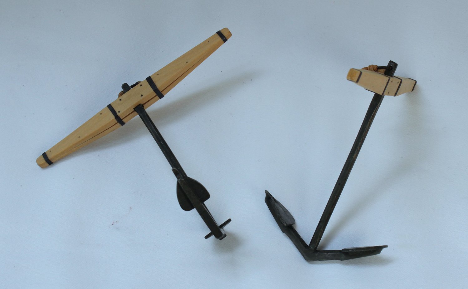
The first step was to make a master anchor from wood. It would have been a lot less work if I had simply made two anchors from wood but I like the look of the metal. I made a box from scrap basswood ply, embedded it in clay and did my first pour. After removing the clay, you can see the result. There are two dowels going through the mold for alignment. The pouring spout is on top and there are relief openings at the end of the flukes. These were too large, preventing the flukes from filling completely, and were reduced after a few unsuccessful pours. The next photos shows the mold after the second layer of rubber was poured before and after the master was removed.
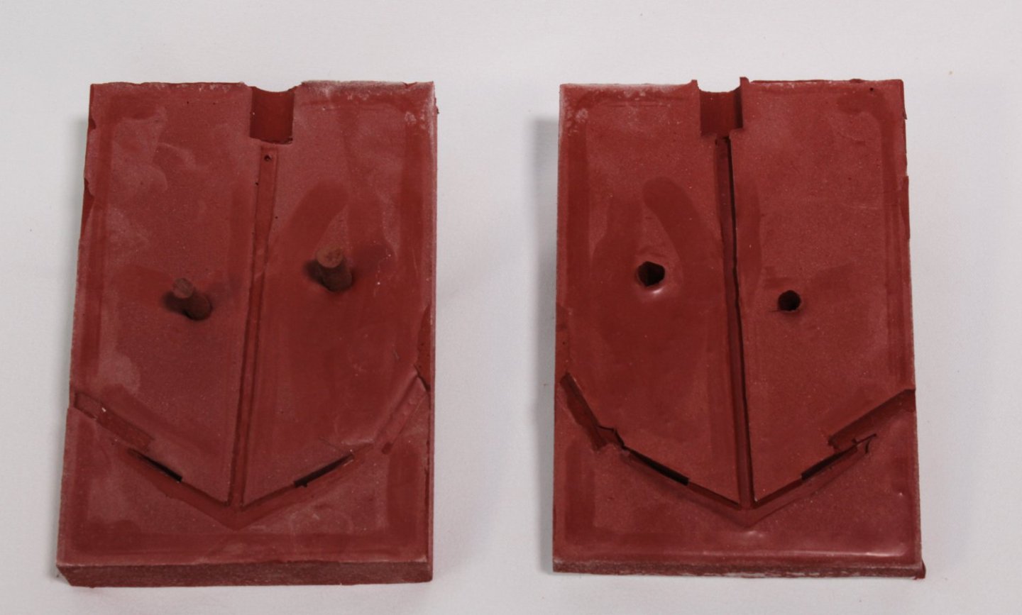
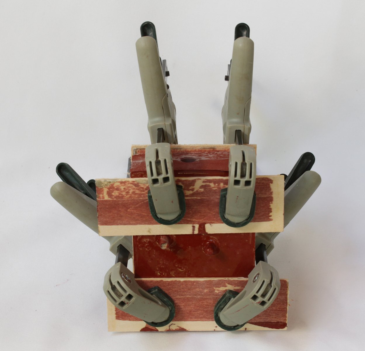
The two mold halves were clamped together, being careful not to distort them with the clamps. I used pieces of the box to distribute the pressure.

- usedtosail, WalrusGuy, mtaylor and 13 others
-
16
-
-
-
Without having the model in hand, it is difficult to be definitive but I would guess that the garboard strake should end halfway between the two fore bulkheads. To give yourself a gluing surface will require a filler piece. It's all a learning experience. Remember, it's only wood. If it doesn't turn out you can remove the planks and re-do it.
-
That looks sweet, Greg.
- Ryland Craze, Keith Black, druxey and 3 others
-
6
-
-
Ken, compare your aft bulkheads with cathead's. You still need to refine them. Draw a line from the fore tip of bulkhead G up to where the counter and sternpost intersect. Everything aft of that needs to be sanded off. Also Ga and Gb need to be sanded down more aft to give a smooth run of planking at the stem rabbet. Finally, the first broad strake looks too wide. This will result in the rest of the planks being too narrow.
As cathead says, battens are your friend. Love those clamps.
-
The double-planked hull gives you the luxury of cobbing it together and using wood filler to compensate any small gaps between the planks. Butt shifting only comes in to play for the visible planking. I presume your two planking layers are a little different width? If they are the same, start your first layer of planking top-down and your second layer bottom-up. Plan on 14 planks amidships, not 13. Remember that you will be sanding a slight bevel into the planks to get them to fit tightly around the curve of the hull. This will be less of a factor at the stern, so you may only need one stealer, instead of two. Overall, your comments epitomize why I have not built a double-plank-on-bulkhead model in at least fifteen years.
if someone could tell me which measurement to divide by 13.2 (planks) to determine the taper from midship to stern, and how you came to that conclusion, that's probably all I need to get moving. Currently I'm thinking of using the 60mm measurement divided by 13.2. Think of the midships as your baseline. So use the midships measurement, 66 mm. Again, there is no such thing as a 0.2 plank. Unless you have access to a few wider planks, divide each bulkhead into fourteen lines of planking. Use a tick strip (a piece of paper the length of the bulkhead) and divide it into fourteen equal sections. Do this for every bulkhead. When the width of the planks exceeds the width of your kit-supplied planking, it is time to insert a stealer and start dividing by fifteen.
The key to the prevention of the smiley-face is taking care not to run the garboard and broad strake too high up the stem. Keep the questions coming!
- Ryland Craze and mtaylor
-
2
-
Mango, take a look at my half hull build log. This goes through the details of planking the hull, what is called "spiling". I think this will answer some of your questions.
At the stern, you should be measuring from the keel rabbet all the way up, just as you did the others. What you will discover is that in order to fill in the space, you will need to add a plank. Also, the aft ends of the other planks will need to be wider than at the midship area.
-
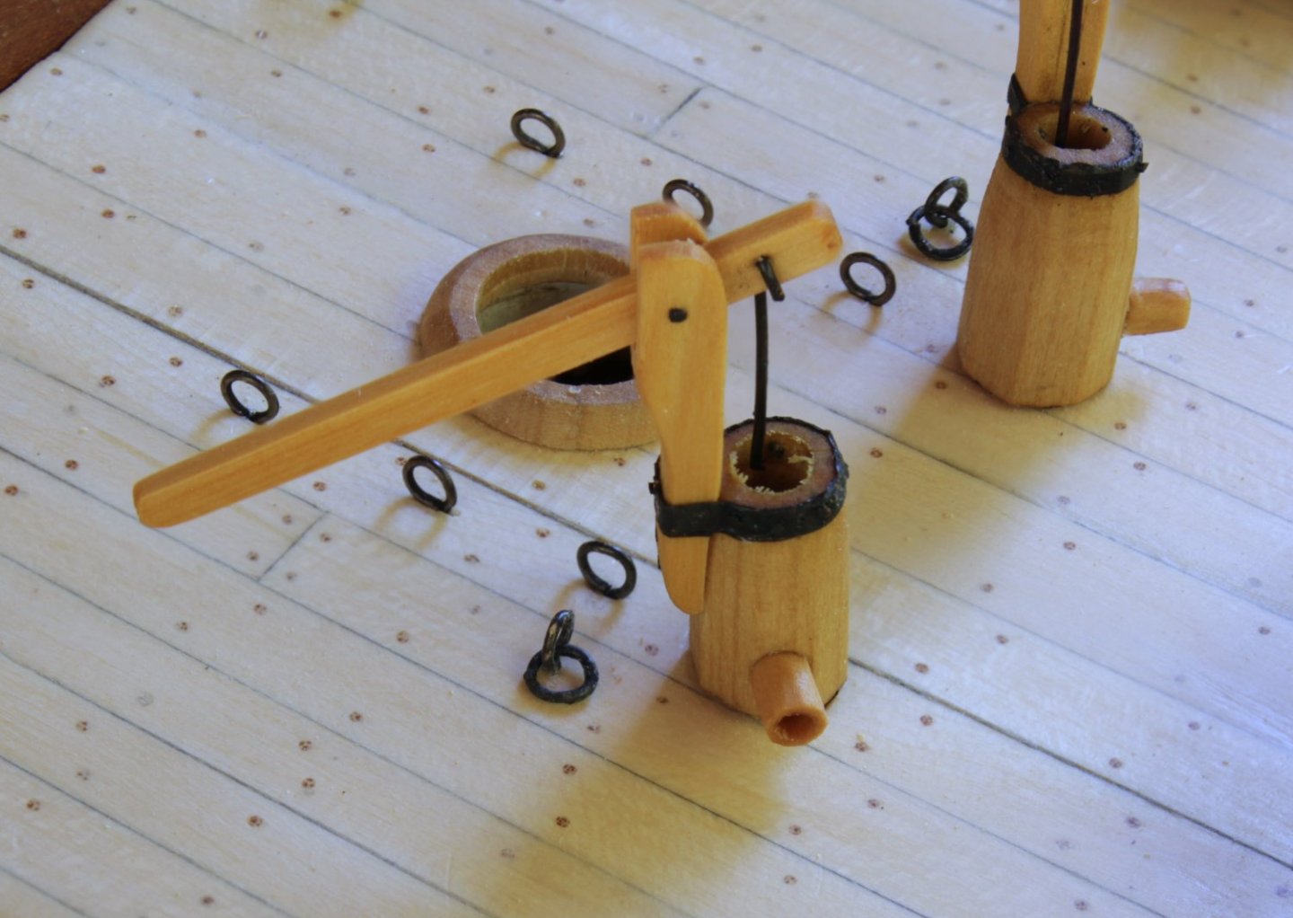
The next items were the pumps. The band on the top of the pump is self-adhesive copper foil, typically used in making stain glass windows. Looks like I need to clean out the inside of the pump!
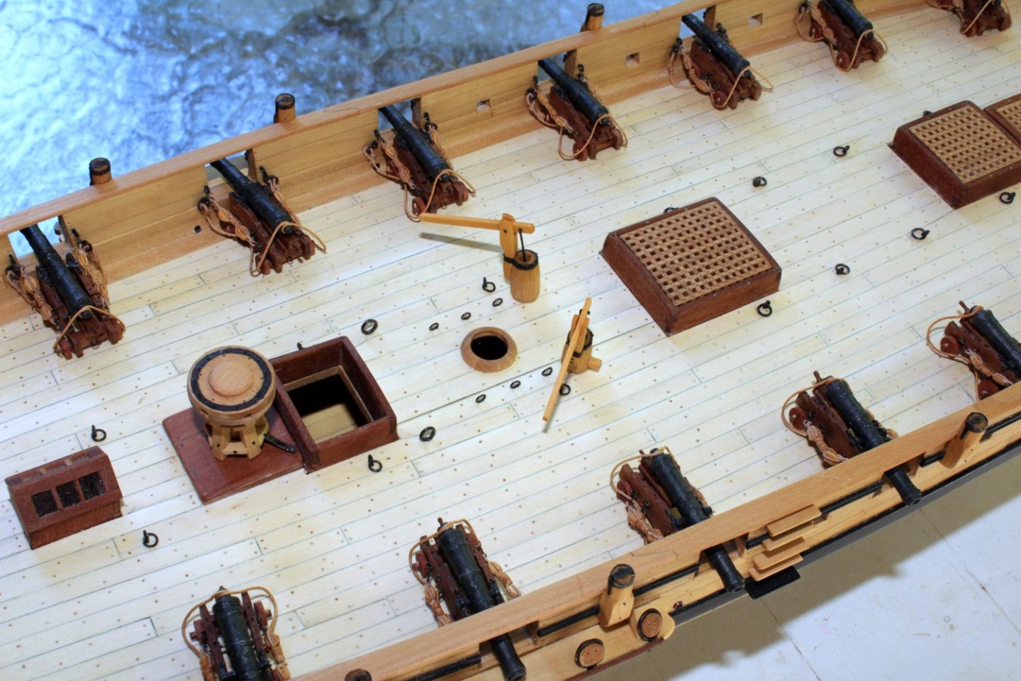
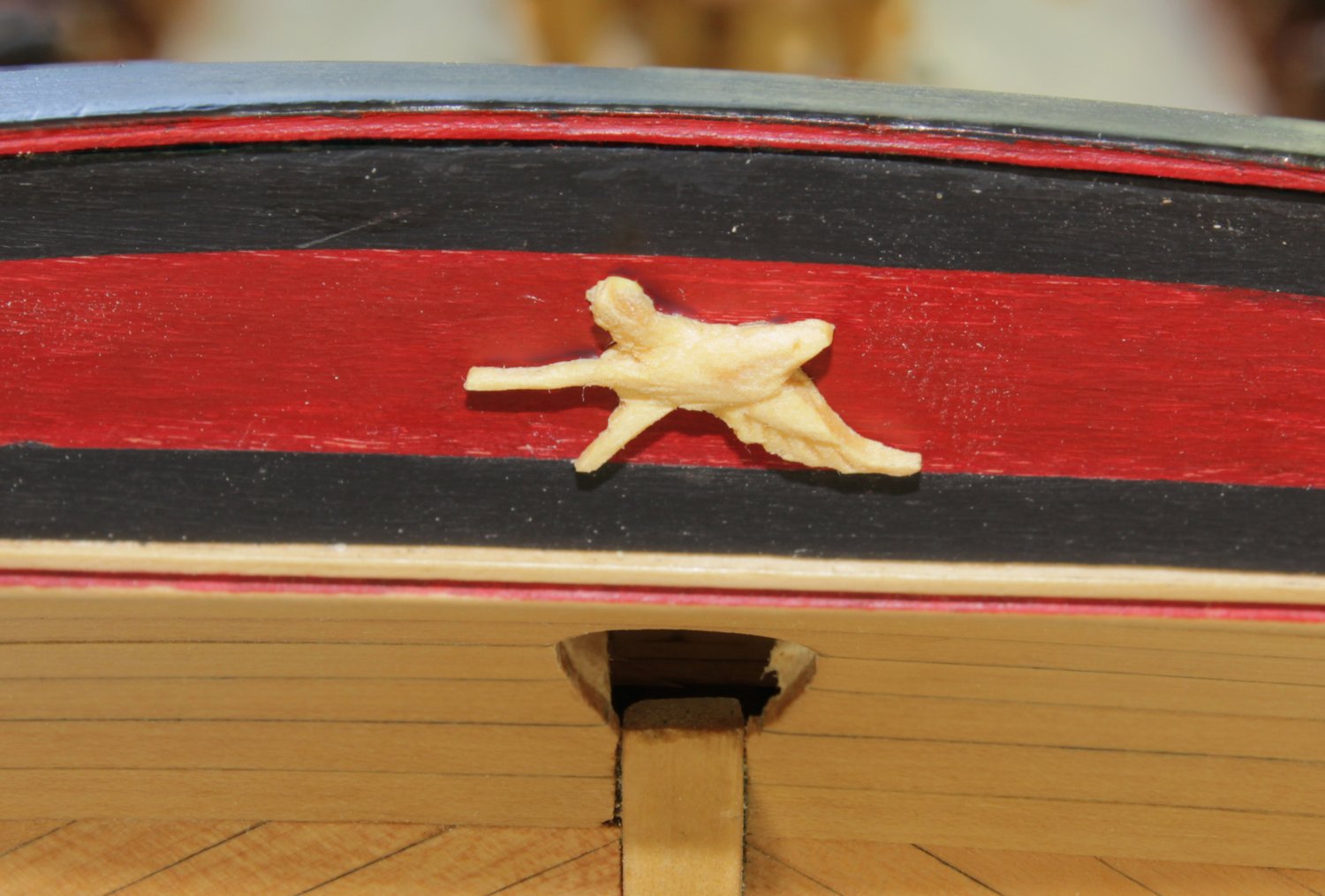
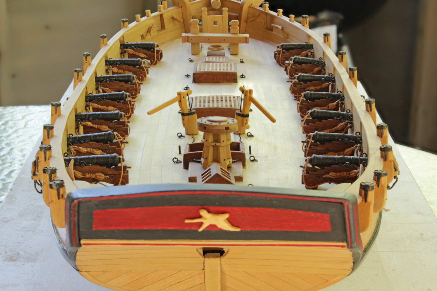
The original model of Swallow shows a carved swallow on the stern. The carving looks better in person than it appears in these pictures. Making the masts is next.


-
As Greg said, the top timber is initially wider. Then, the aft portion of the upper part of the timber is sanded down and the fore portion of the lower timber is sanded. In his picture you cannot tell that the entire timber is narrower because the band is hiding the joint. If you go to the first post in my Echo (link in my signature) you can see the frame in question.
-
Thank you, sir. And thanks to everyone who has been following the slow progression of this build.
- hollowneck, Cathead, mtaylor and 3 others
-
6


Swivel guns
in Discussion for a Ship's Deck Furniture, Guns, boats and other Fittings
Posted
I ran into the same problem, Allan. On my plans from the RMG, the tops of the swivel mounts are all the same distance from the top of the deck at the bulwark, 48".