


fake johnbull
-
Posts
128 -
Joined
-
Last visited
Content Type
Profiles
Forums
Gallery
Events
Posts posted by fake johnbull
-
-
Jaager,
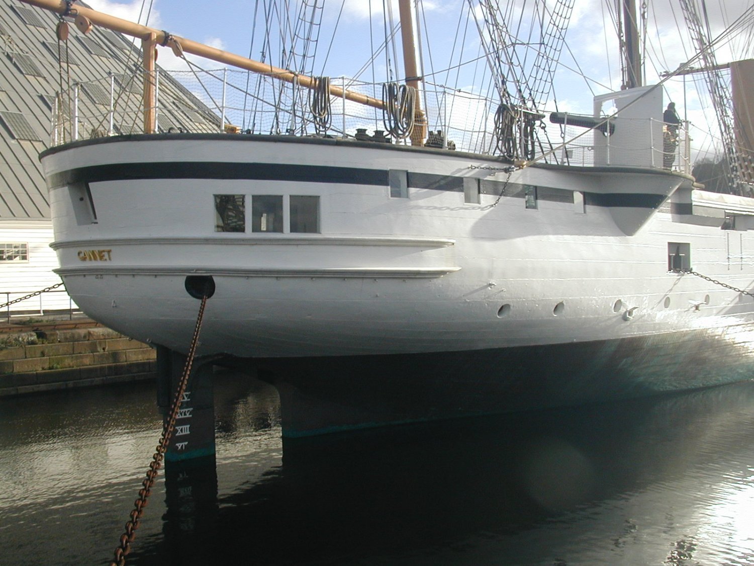
Firstly I'm sorry if my term "round stern" mislead you. You maybe refer to sterns of ships like Gannet or ironclad Achilles.
Gannet photo by myself

Achilles from NMM (https://www.rmg.co.uk/collections/objects/rmgc-object-66902)
I
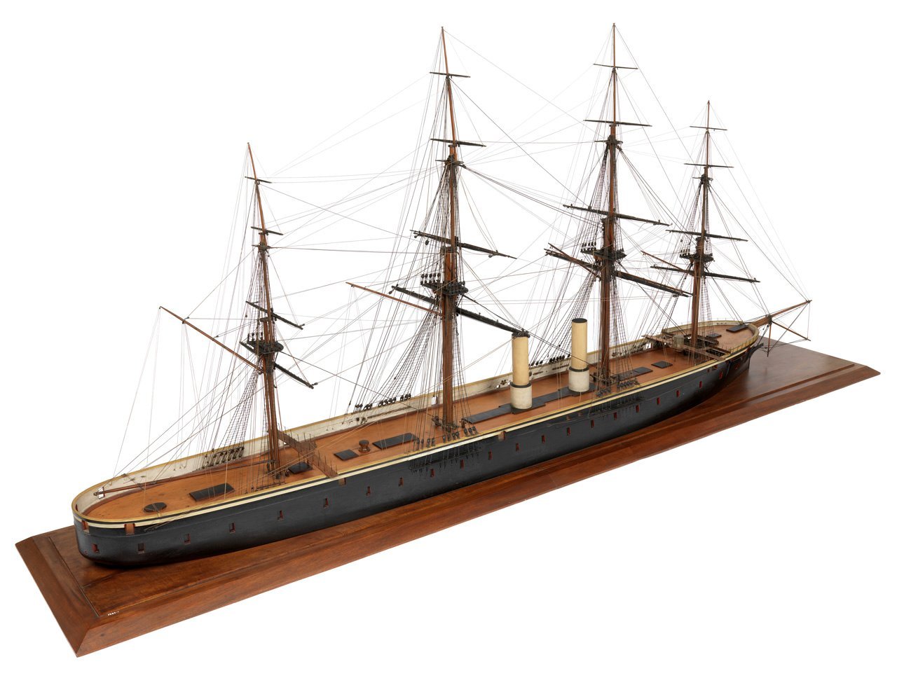
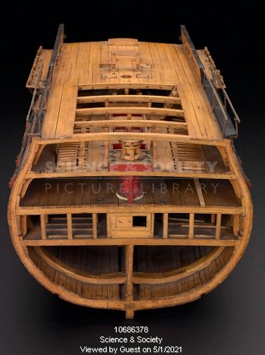
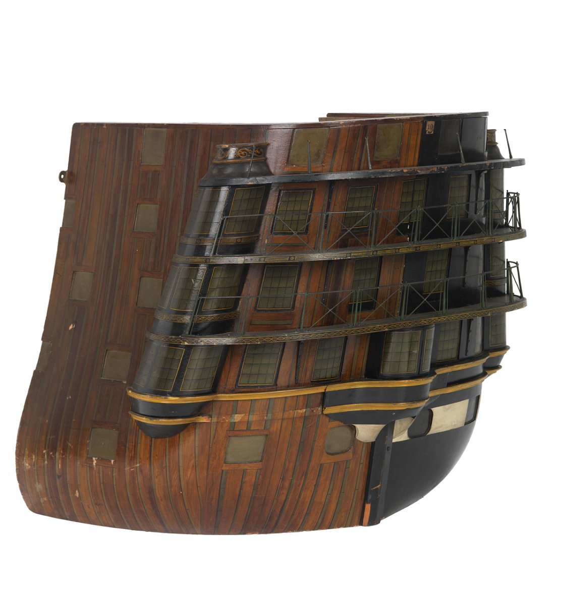
I intended to refer to round stern introduced by Robert Seppings but unpopular amongst officers as ugly and uncomfortable.
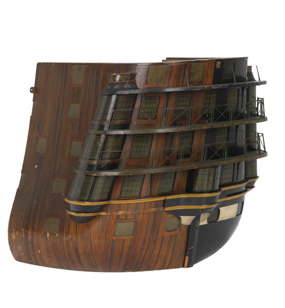
Queen Charlotte from NMM (https://www.rmg.co.uk/collections/objects/rmgc-object-68226)
My appology again.
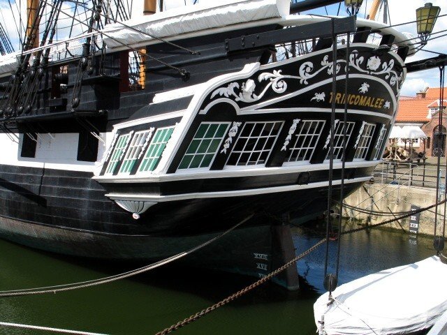
BTW, your mentioning on Leda class frigates reminds me of two survivors amongst them.
Trincomalee from wikipedia (https://commons.wikimedia.org/wiki/File:H.M.S._Trincomalee,_Hartlepool_Maritime_Experience_-_geograph.org.uk_-_1604022.jpg)
Unicorn from wikipedia (https://commons.wikimedia.org/wiki/File:HM_Frigate_Unicorn,_from_the_stern_-_geograph.org.uk_-_1316939.jpg)
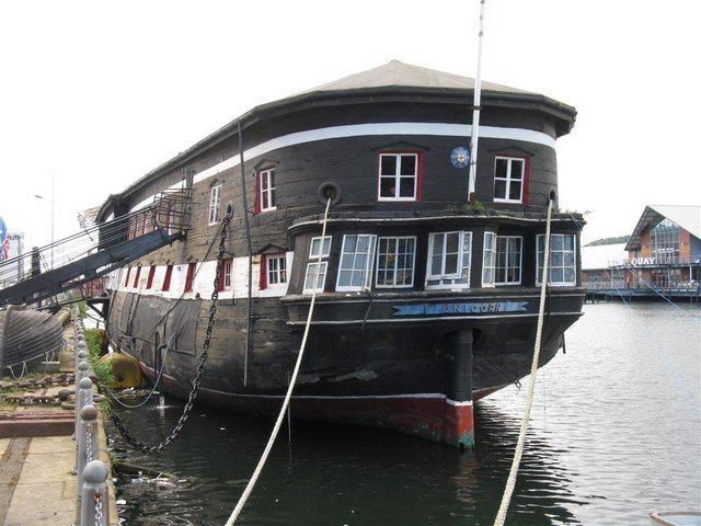
Unicorn has upper cabin as hulk and Trincomalee also once had upper cabin in her training ship era, so there would be some changes from their original appearance. But variations of stern shape in one class are shown in them and we are very fortunate to have these two existing examples.
Kindest regards,
Mitsuaki
-
Jaager,
Thank you for your explanation. I don’t know if this is suitable for example of anachronism, we often see mid-18th century French ship with tricolor flag or 17th century English ship with Union flag containing St. Patrick Red X Cross.
Also I don’t know if this is suitable for example of sentiment to old days, elliptical stern would be one of revival of old stern appearance against unpopular round stern.
Kindest regards,
Mitsuaki
-
jaager, Allan, Gregory and Mike,
Thank you for your reply. I agree these fittings are subjects of changes by preference of Captain, Sailing Master or boatswain.
jaager suggested the importance of “avoid anachronism“. In this sense, I believe U shaped staghorns had became old-fashioned till Trafalgar days. (I’m sorry if I misunderstand jaager’s intention.)
jaager and Allan,Pinrails are kit laser-cut parts. Maybe large holes are results of belaying pins from Amaty’s stock parts. I agree finer pins and holes are much better.
Gregory,
I agree that there is a possibility of difference of angles are result of incorrect repair of later days.
Kindist regards,
Mitsuaki
-
After some consideration, I've determined to adopt mixture of (or compromise between) Bellona coppered model and Victory. Three kevels are referred to Bellona coppered model and staghorn and pinrails are referred to Victory.
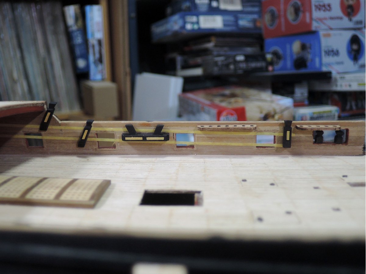
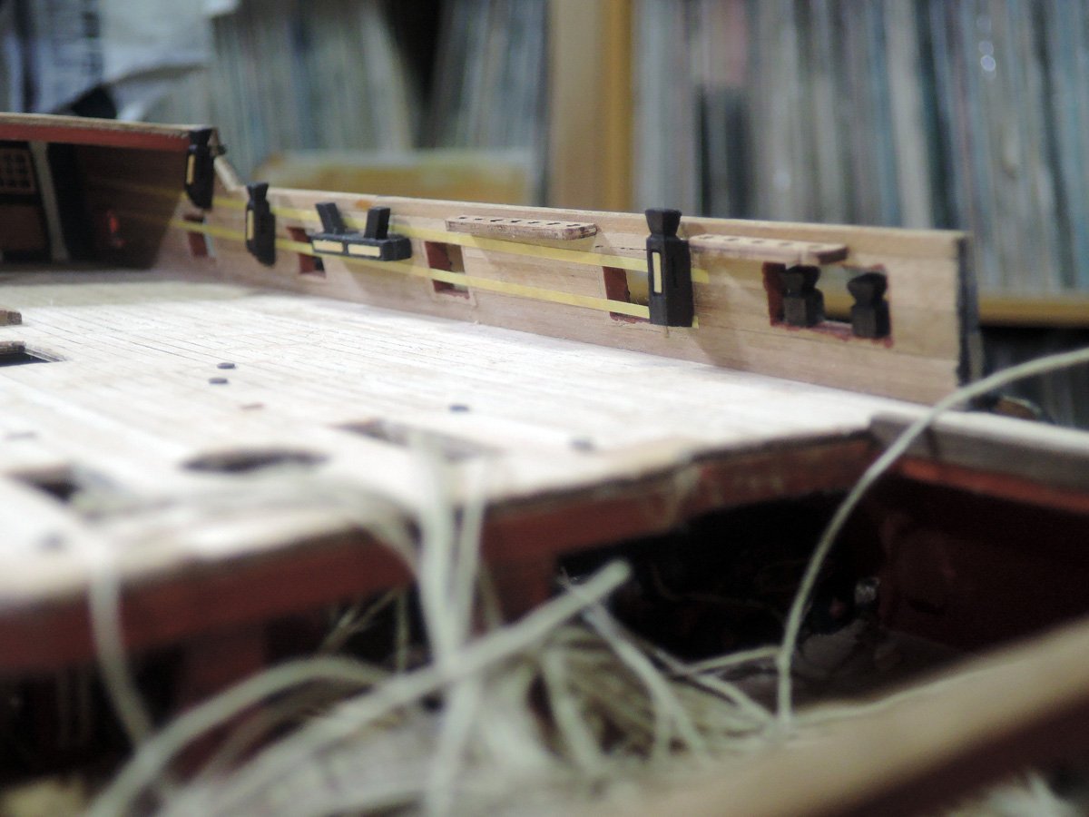
I only hope my interpretation is not far from original😅 Of course this is only my assumption and any suggestion or opinion from other aspect are welcome.
BTW. I noticed some interesting (or annoying) fact while researching belaying positions of this era.
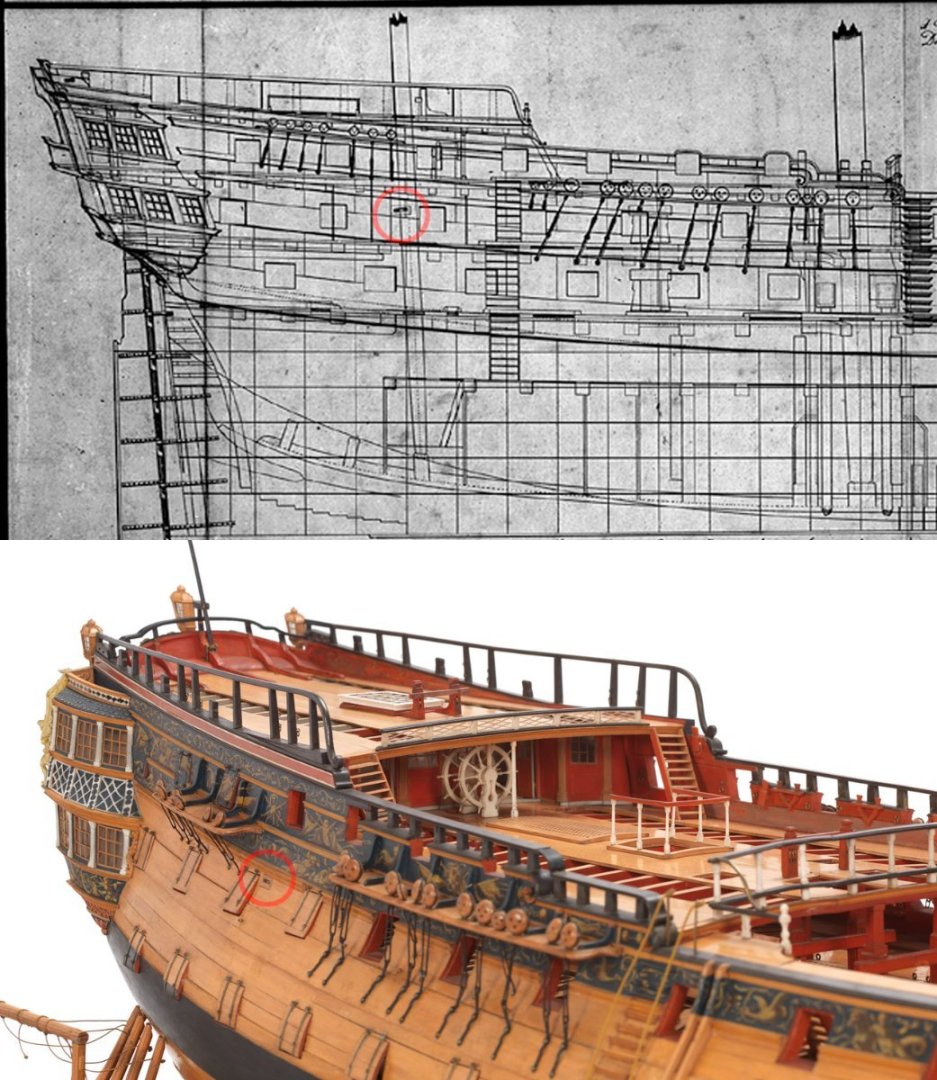
1. Quarterdeck gunports of Bellona coppered model are positioned aft than plan shows. This difference of gunports positions also gave influence to deadeye positions of main channel. I don't know precise reason why, but I assume that this model was made for examination of new gunport arrangement including Carronades as well as promotion of coppering to the King.
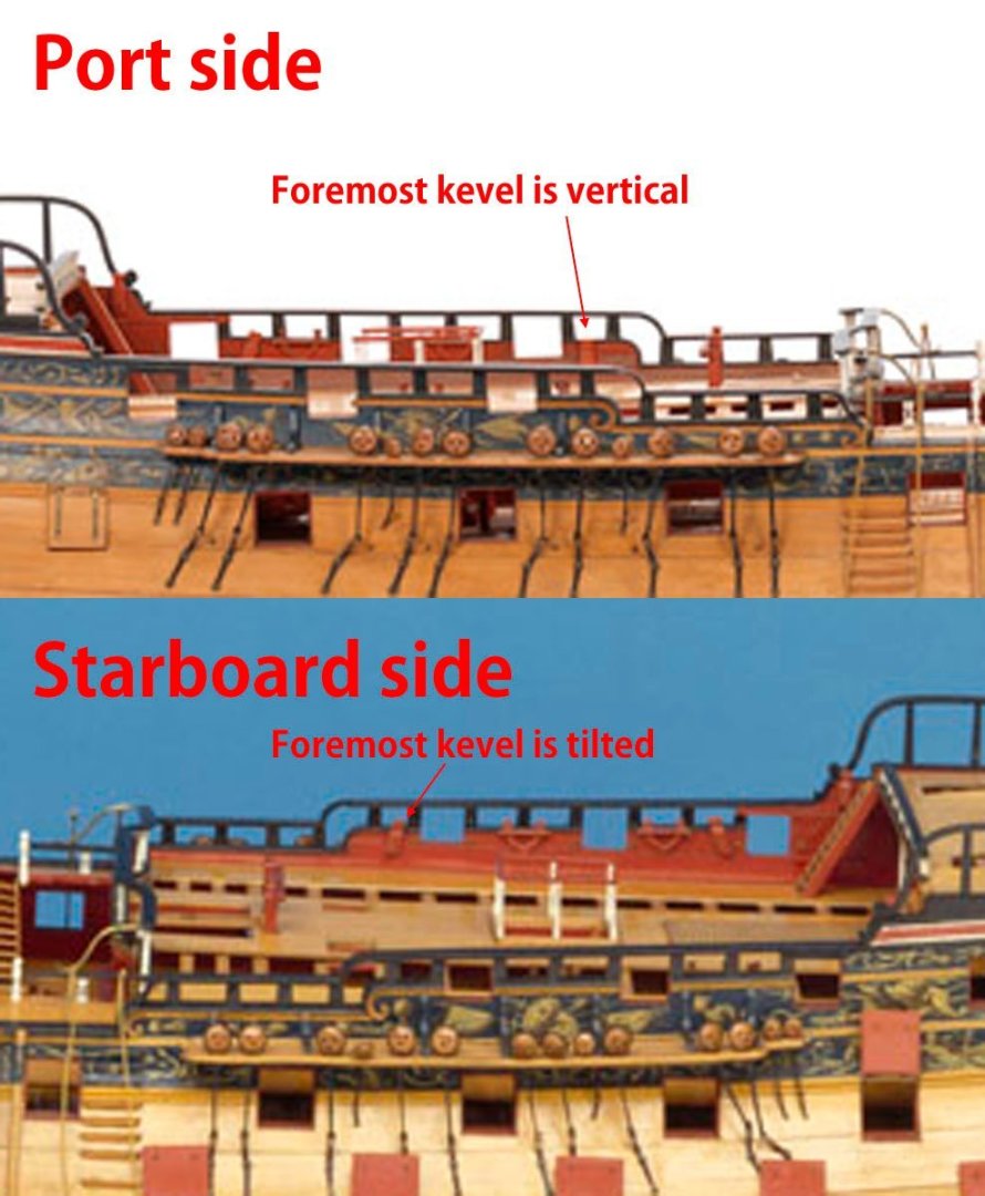
2. The angle of foremost kevels of quarterdeck of Bellona coppered model are different from port to starboard. Port one is vertical and starboard one tilted to aft. I have no idea the reason why, but if main lower lifts are belayed here, vertical ones seems to be more natural.
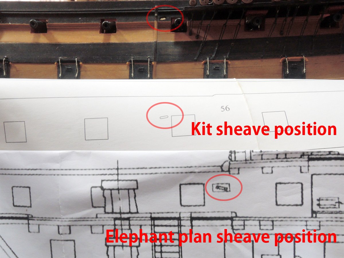
3. Main course sheet sheave-hole position are defferent between Bellona copperd model and Elephant plan. While that of Bellona model is positioned forward of the third gunport to last, that of Elephant plan is aft of the third gunport to last. I once wrote identical plan maybe used for construction of Bellerophon, but I noticed that this sheave-hole position is somewhat unnatural considering sheet lead to this position is interfering gunnery. Again I have no idea why, but there would be some possibility that draughtsman who wasn't familiar with rigging draw sheave-hole to this positon.
Kindest regards,
-
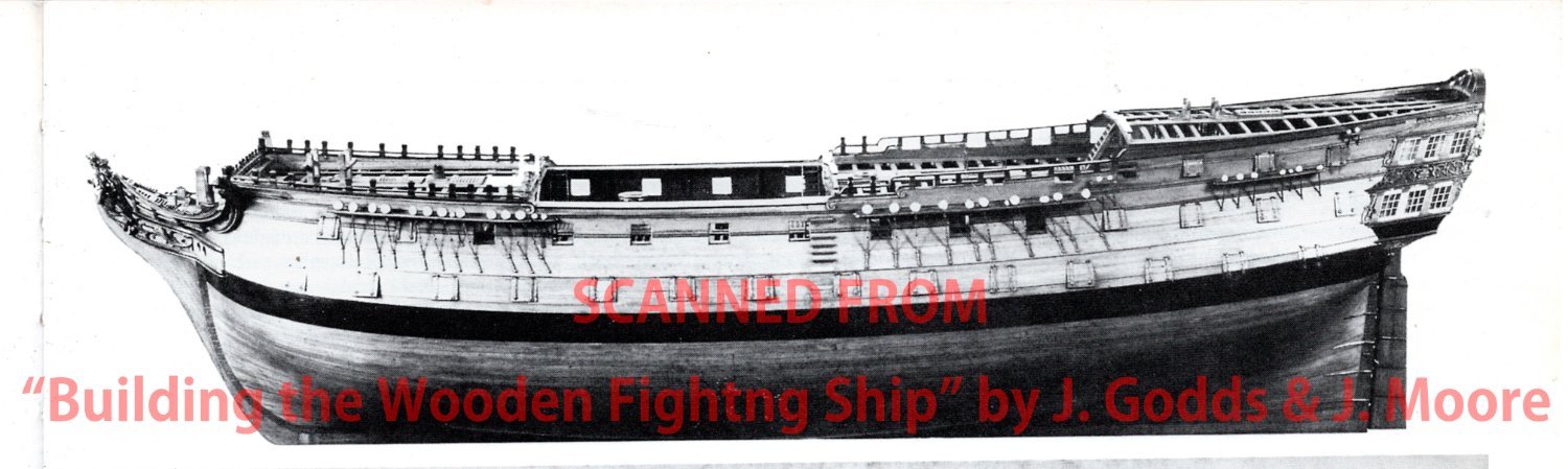
Allan, thank you for your suggestion. Hercules or Thunderer model is important and beautiful one and also appeared on jacket cover of Lees's "Masting and Rigging".
But I gave up to refer this model because of reasons below.
1. Masting and rigging of this model is modern addition. Of course, rigging of this model had might been done by expert of the museum, so it is thought to be almost accurate.
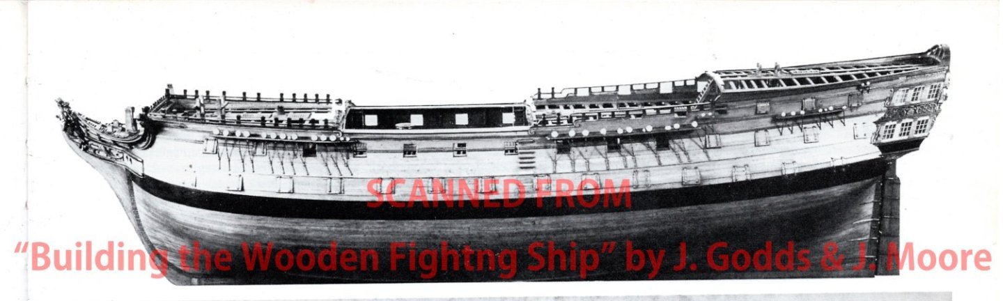
Image below is scanned from "Building the Wooden Fighting Ship" by J. Dodds and J. Moore, and I believe this is same model before addition of rigging. But this photo seems to be having no sheave-hole on side as well as chestree or fenders. Photos of this model after addition of rigging are showing sheave-holes for main course tack and fore course sheet, but any kind of hole for main course sheet isn't added. Instead main course sheet is lead through gun port under main channel, but I think this is expedient way to add main course sheet.
2. Photo of above seems to be having no belaying points on inside of quarterdeck bulwark. Photos of members only page of this model is also suggest it.
https://modelshipworld.com/gallery/image/9197-dsc01392/?browse=1
But anyhow, this model can be safely said as one of masterpiece of contemporary works and many finding can be found.
Kindest regards,
-
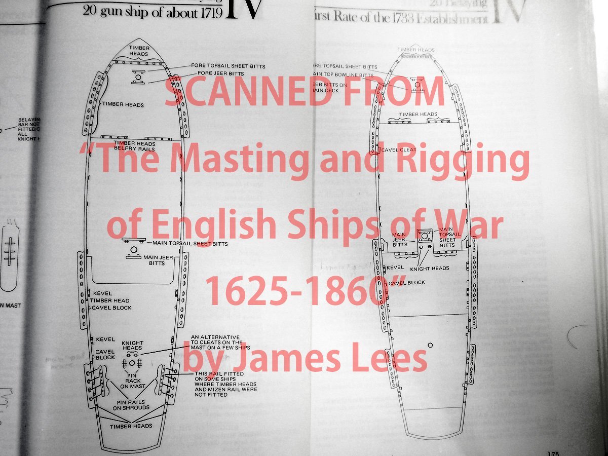
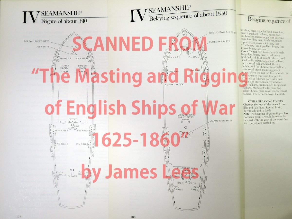
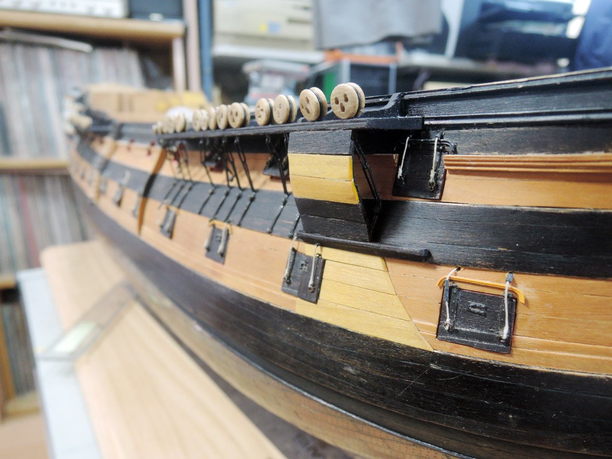
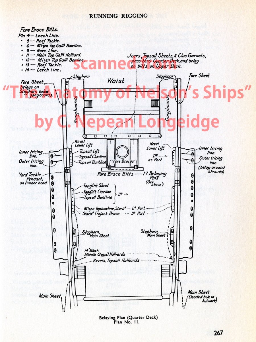
I’ve recentry re-started building of Bellerophon after I finished other modelling project, but two concerns on rigging prevent me from further progress of building. One is what most likely arrangement of her belaying points on inside of quarterdeck bulwark is, and another is what most likely method to lead main course sheet is.
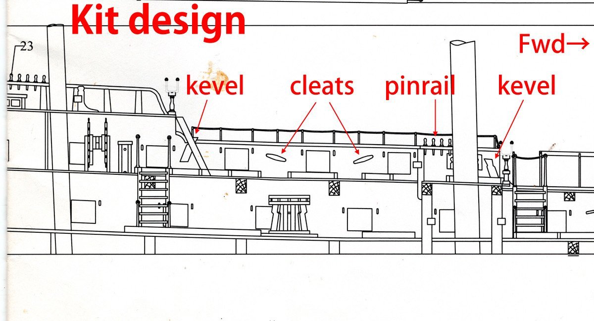
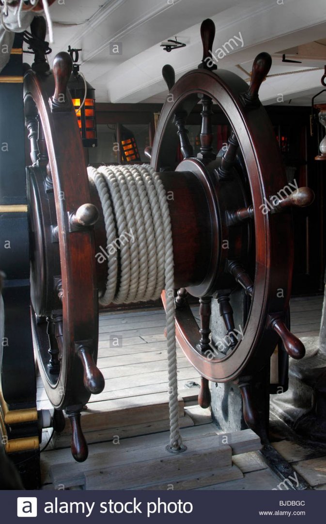
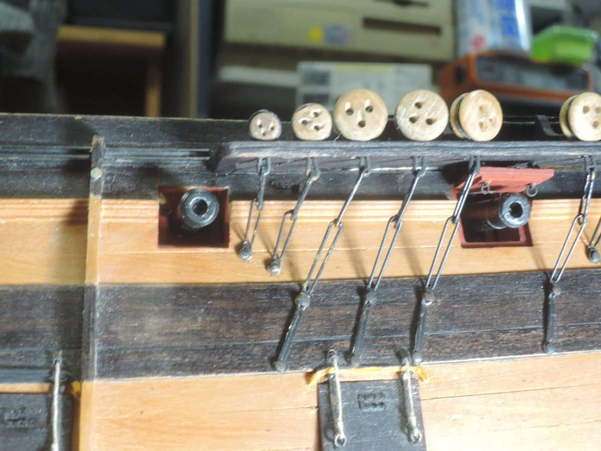
Firstly, question on belaying point. Kit design shows two cleats here.
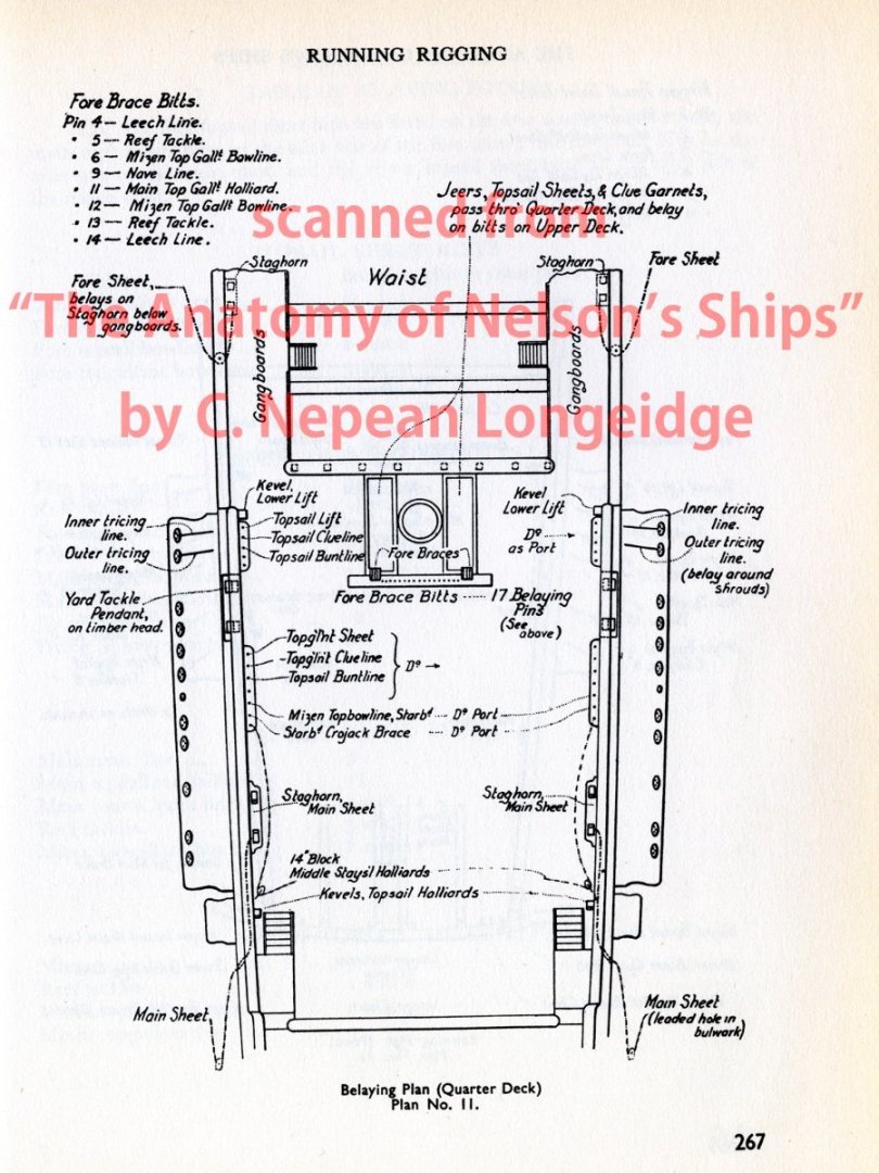
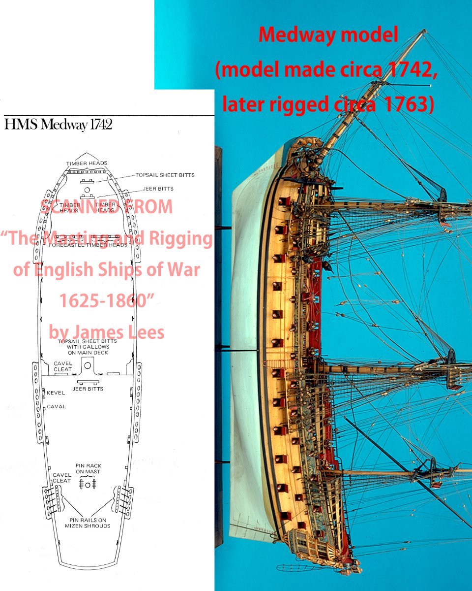
But belaying plan of 18th century ships appeared on Lees show no cleats here, although belaying plan of frigate of 1810 and 1850 ships show cleats here. Also some of contemporary models or Victory today have staghorns here instead of cleats.
Lees "Masting and Rigging"

Meway model
https://www.rmg.co.uk/collections/objects/rmgc-object-66289
Bellona
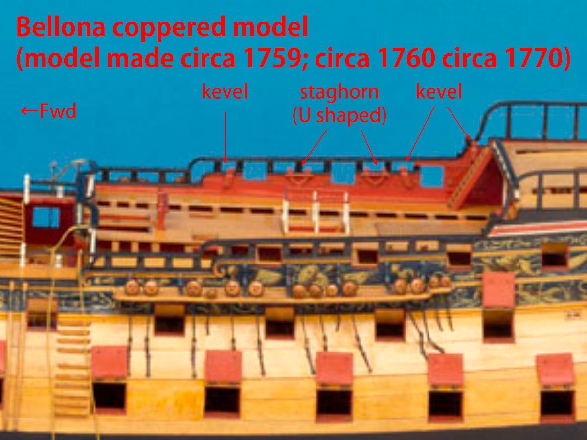
https://www.rmg.co.uk/collections/objects/rmgc-object-66299
Royal George
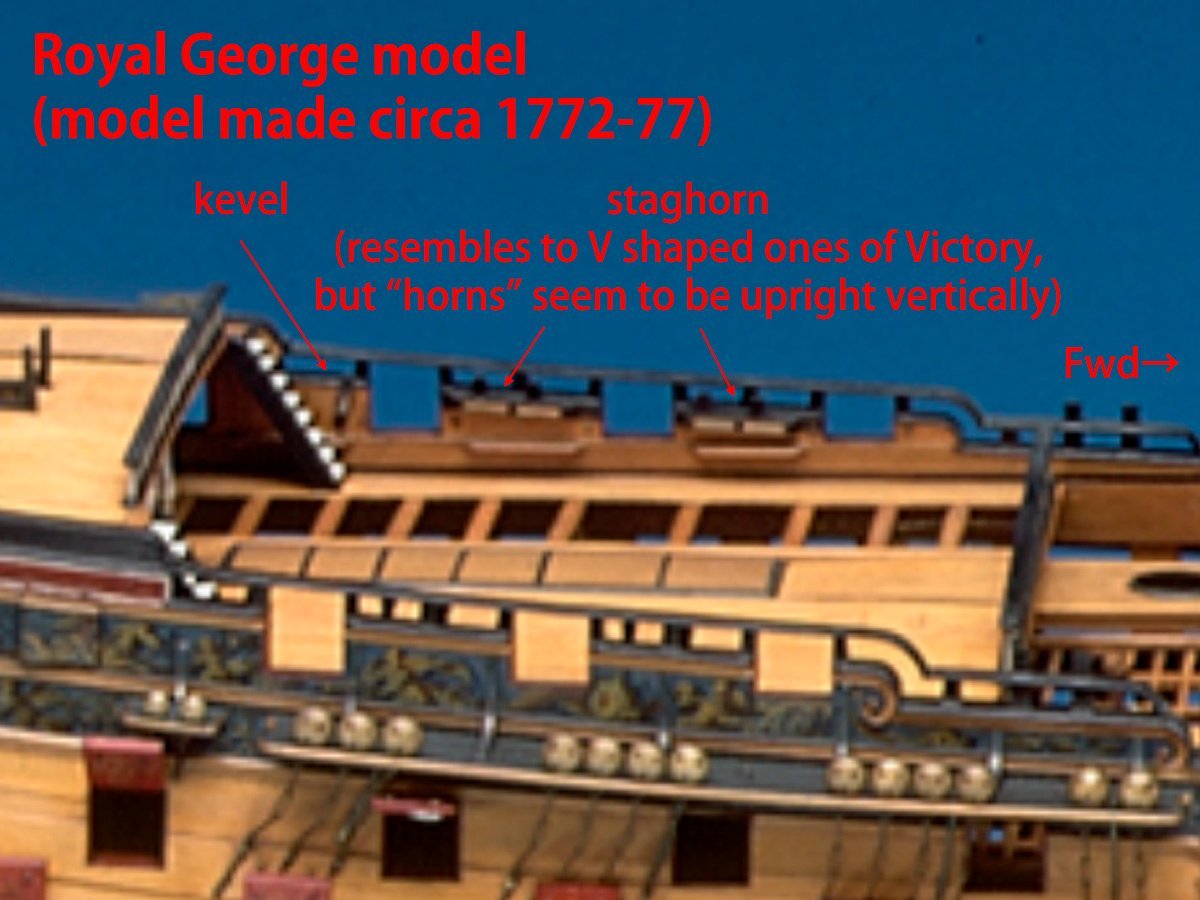
https://www.rmg.co.uk/collections/objects/rmgc-object-66297
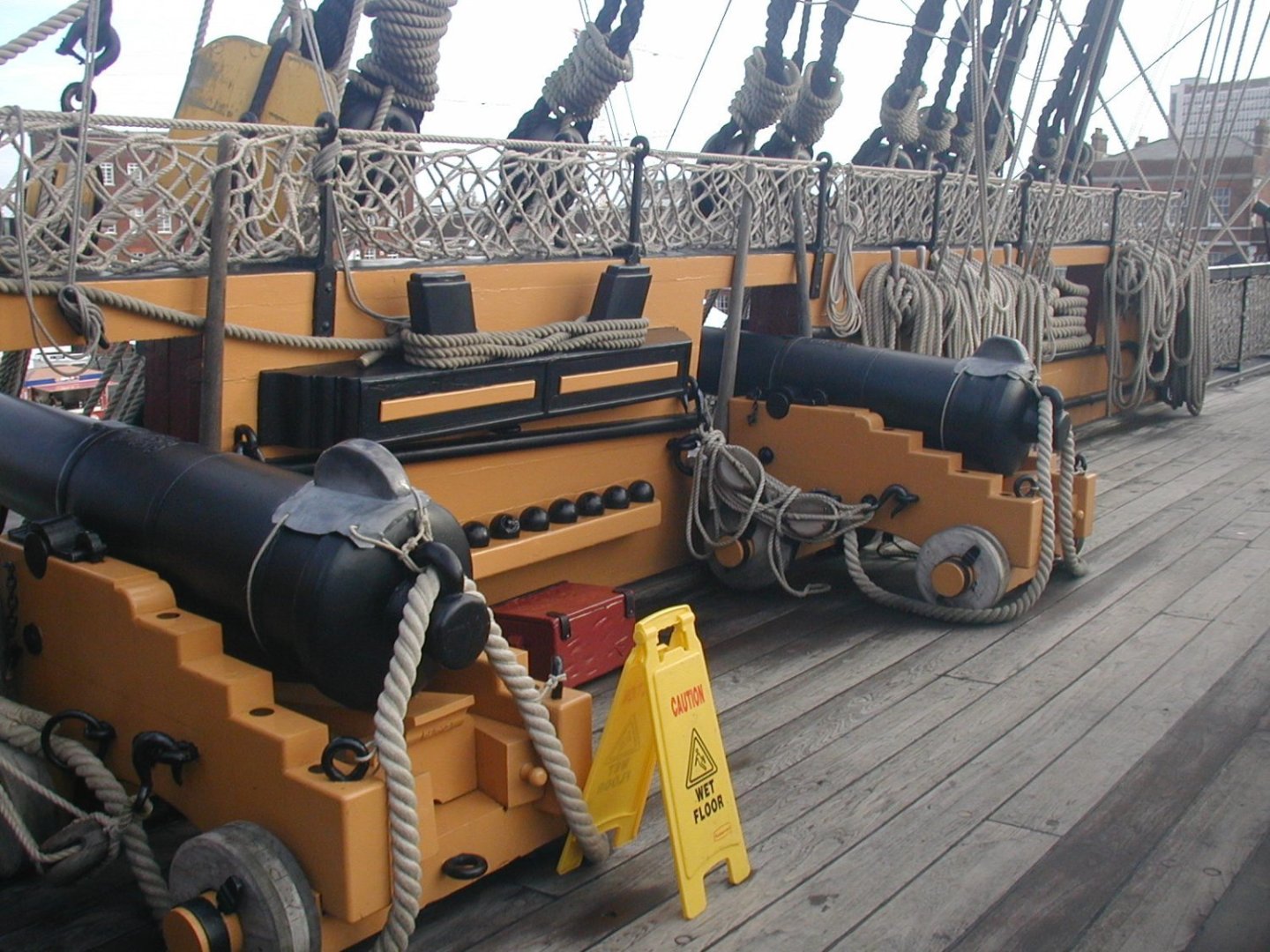
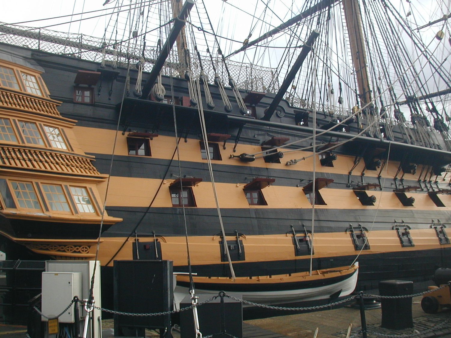
Victory has V shaped staghorn.
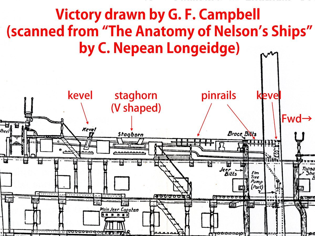
Photo by myself.
ONTH Model of 64 gun ship of 1775 seems to be having cleats here.
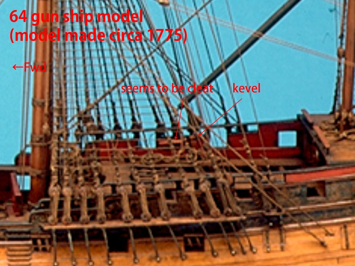
https://www.rmg.co.uk/collections/objects/rmgc-object-66274
Images of this same model on members only page of this site suggests that rope is passing through sheave of angled kevel then belayed this cleat-like fitting. But I assume that cleats on this place are rare in 18th century ships of the line.
https://modelshipworld.com/gallery/image/5205-london-525/
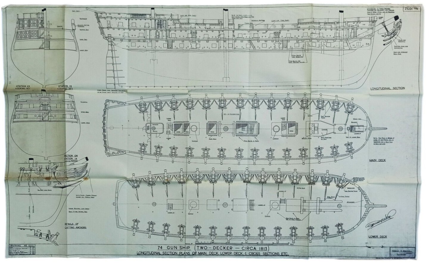
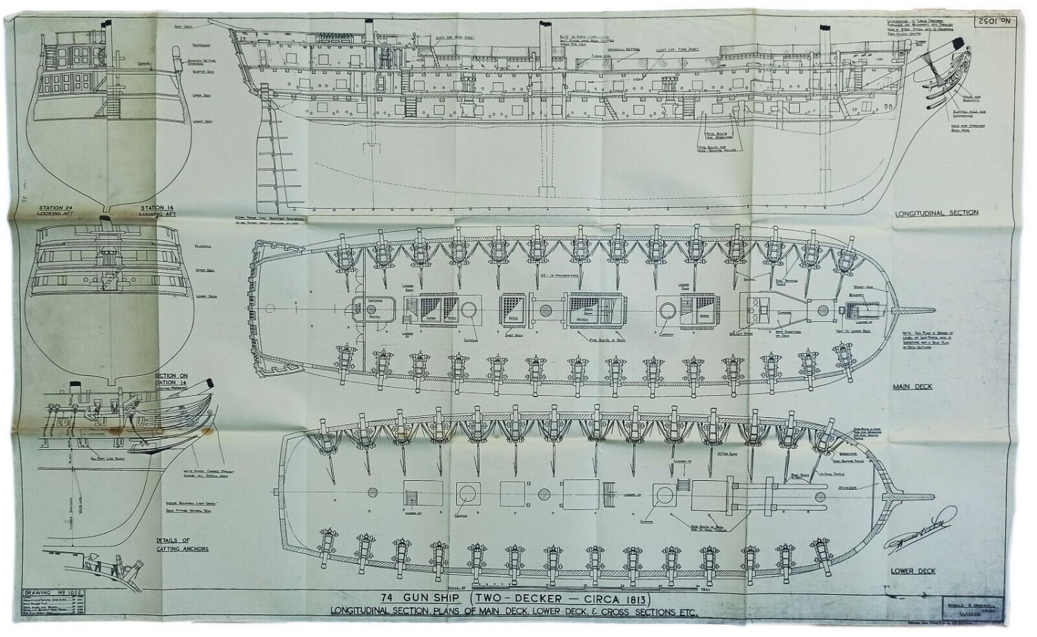
Plans of 74 gun ship of 1813 drawn by Underhill shows cleat to belay main course sheet.
Model of Hastings of 1818 also seems to have cleats. This is sailor’s made model, so fittings must be authentic.
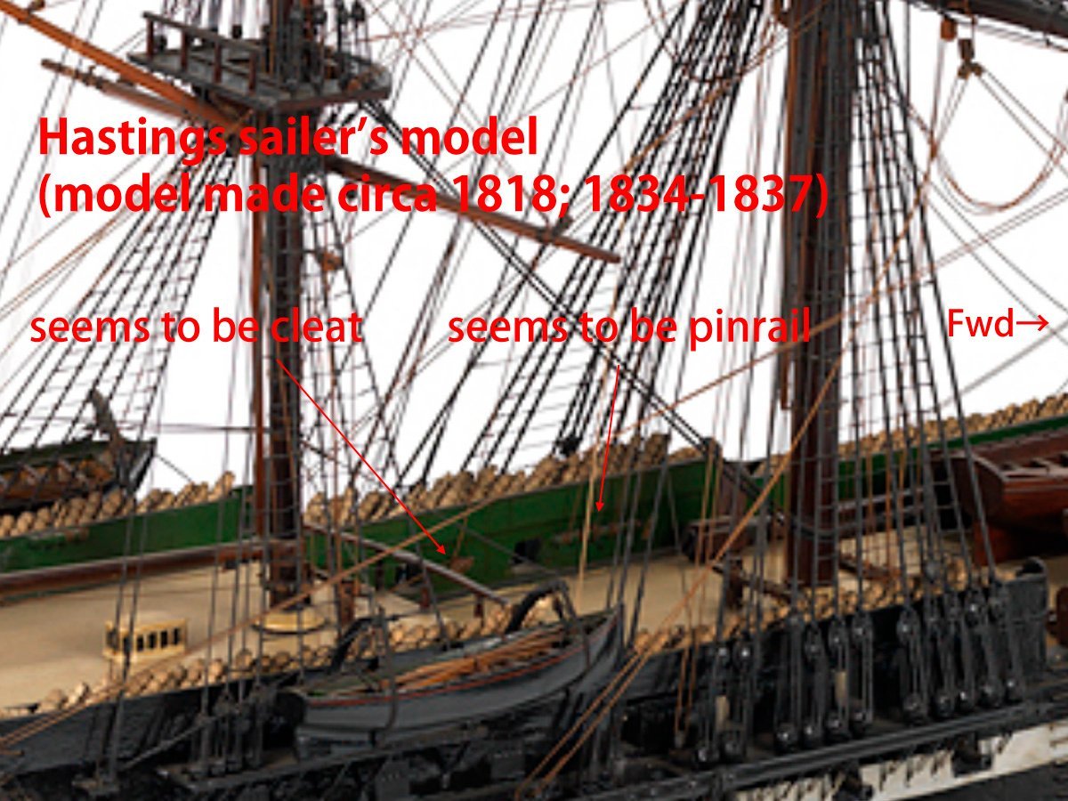
https://www.rmg.co.uk/collections/objects/rmgc-object-66653
From these examples, my best guess is that staghorns had been used with change of appearances from U shaped to V shaped around some date of late 18th century, then sometime after Trafalgar cleats replaced staghorns. But I’m still anxious for my guess.
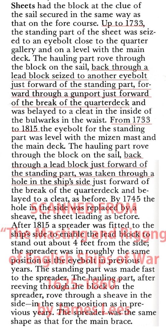
Then second question, how to lead main course sheets.
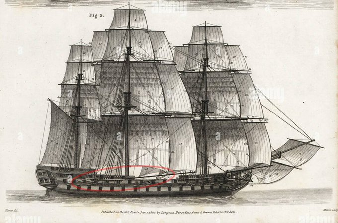
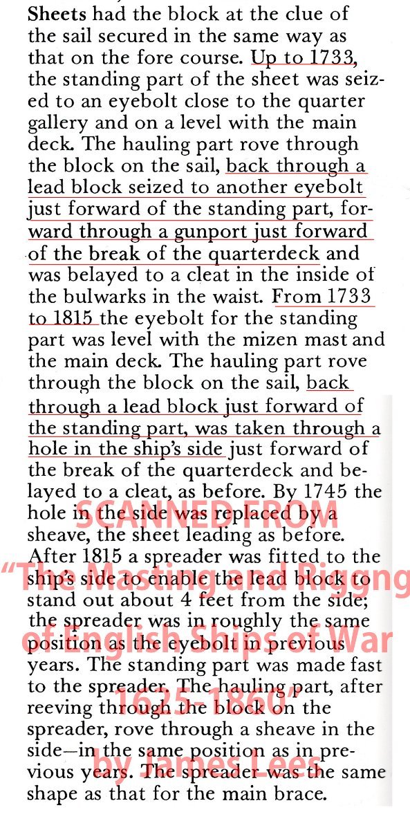
Steel depicts that sheet is lead backward from clew, then passing through sheave-hole of ship’s side and belayed to a range-cleat in the waist.
https://maritime.org/doc/steel/part7.php#pg211
This image is I found on google image search and I believe this is taken from “Rees’s Naval Architecture”.
64 gun ship model of 1775 also shows sheave-hole to lead sheet into hull.
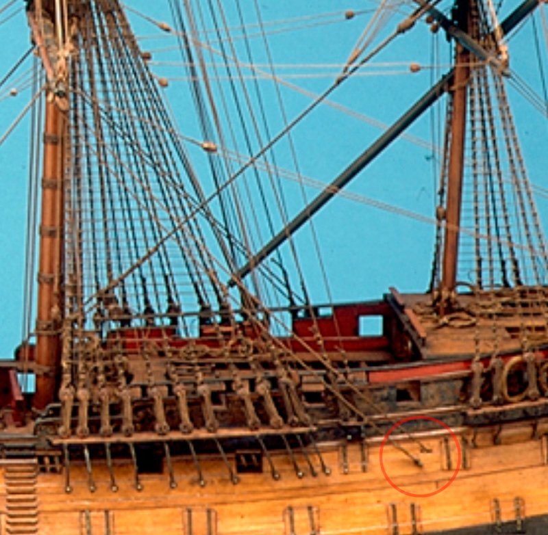
ONTH Lees depicts that sheet is lead backward from clew , then turned forward through block and hauled into hull.
This method can be seen on Victory today (photo by myself). Some of contemporary models is also showing this method.

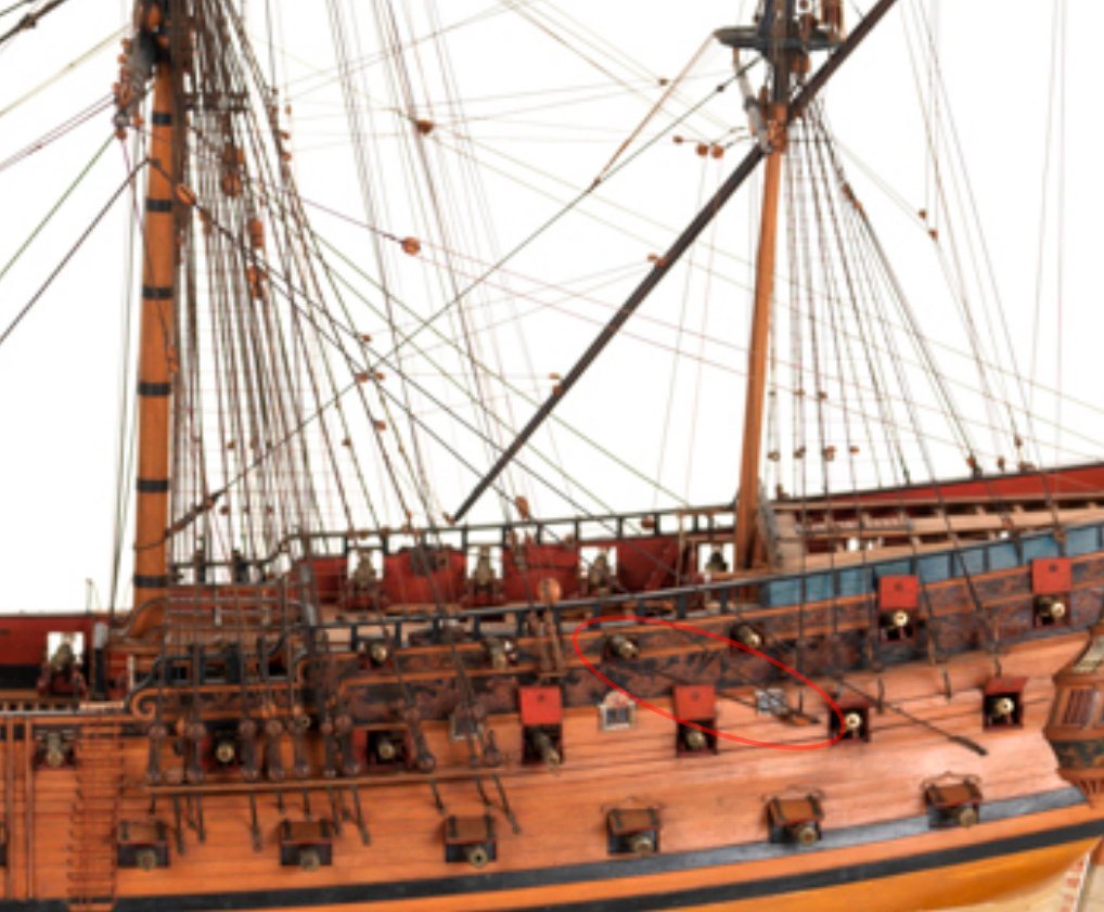
https://www.rmg.co.uk/collections/objects/rmgc-object-66407
Although this is depiction on 17th century ships, Dr. Anderson depicts both methods were used on English ships, though sheave-hole method were mainly used.
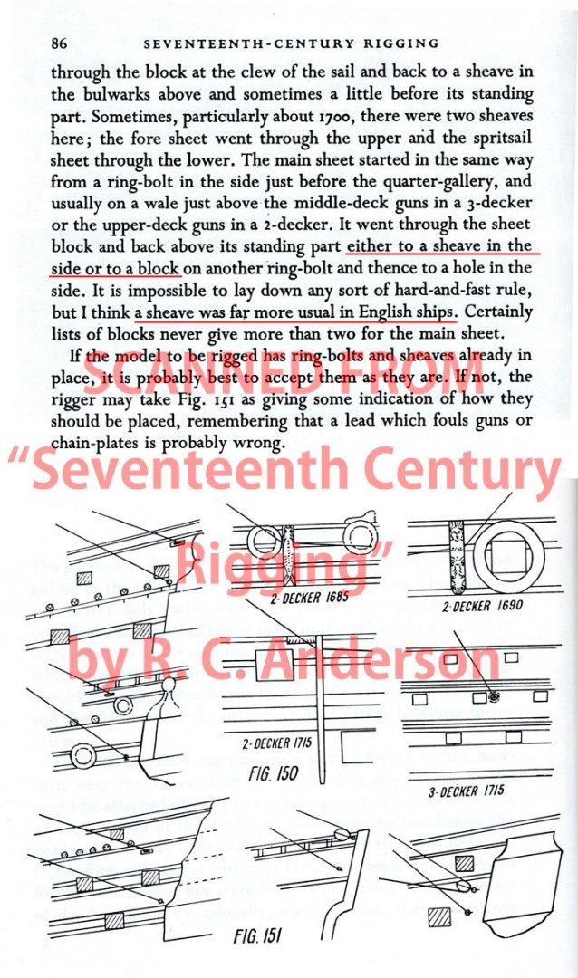
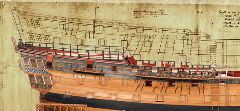
My best guess is Bellerophon had sheave-hole on her side. Internal profile plan of her sister ship Elephant which Chris Watton based on for his Vanguard/Elephant/Bellerophon kit design is clearly showing it at mizzen mast position. Both of Bellerophon and Elephant were ordered from private shipyards and launched almost same time, so both ships must had been constructed on identical plans manually copied.
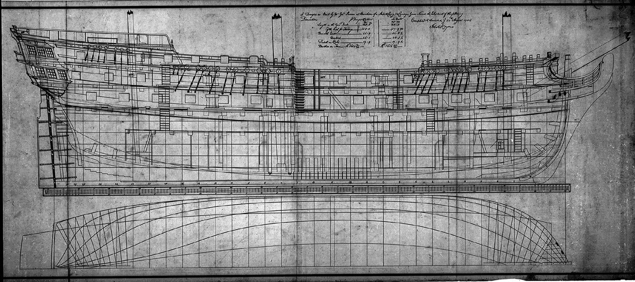
https://images.rmg.co.uk/asset/12418/
But in the case of sheave-hole method, belaying points on the inside of quarterdeck become useless. Kit rigging plan shows main topsail halyard and shifting backstay fall is belayed to cleat, but Victory shows the former belayed to angled kevel and latter tied to hook of lower block of tackle.
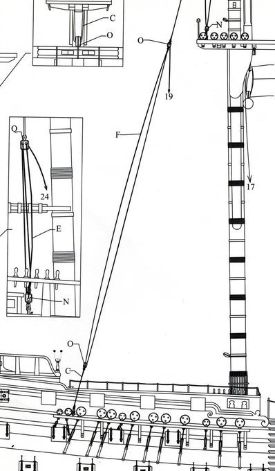
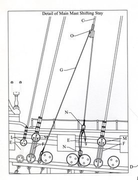
I’m now inclining to the idea to fit my Bellerophon with belaying points based on those of Victory today except staghorn left unused for alternative belaying point for main course sheet.
But again I’m anxious for my idea and it is very appreciated to hear other possible method from members here.
Kindest regards
Mitsuaki Kubota
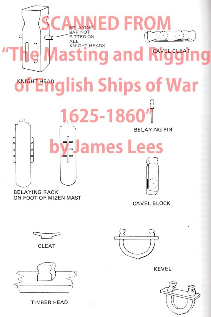
Note on glossary
Sometimes the usages of maritime terms are deferent from one author to another. Lees or other authors use the term “kevel” for U shaped belaying point and “cavel block” for timberhead like fitting with sheave. ONTH Longridge or Lavery use the staghorn for U or V shaped belaying point and kevel for timberhead like fitting with sheave. For convenience I followed usage of Longridge or Lavery.
-
-
Peter,
Thanks for your reply.
Deck planking method is one of aspects which are often neglected, but really interesting topic.
Judging from two models of Diana held by NMM, gangway is separated structure from fo'c'sle deck and quarterdeck circa 1790s, although these examples are of frigates, not ships of the line.
https://collections.rmg.co.uk/collections/objects/66533.html
https://collections.rmg.co.uk/collections/objects/66303.html
BTW, I'm delightful to see your Bellerophon is showing common improvement with me including anchor lining👍
- GrandpaPhil, mort stoll, flyer and 3 others
-
 6
6
-
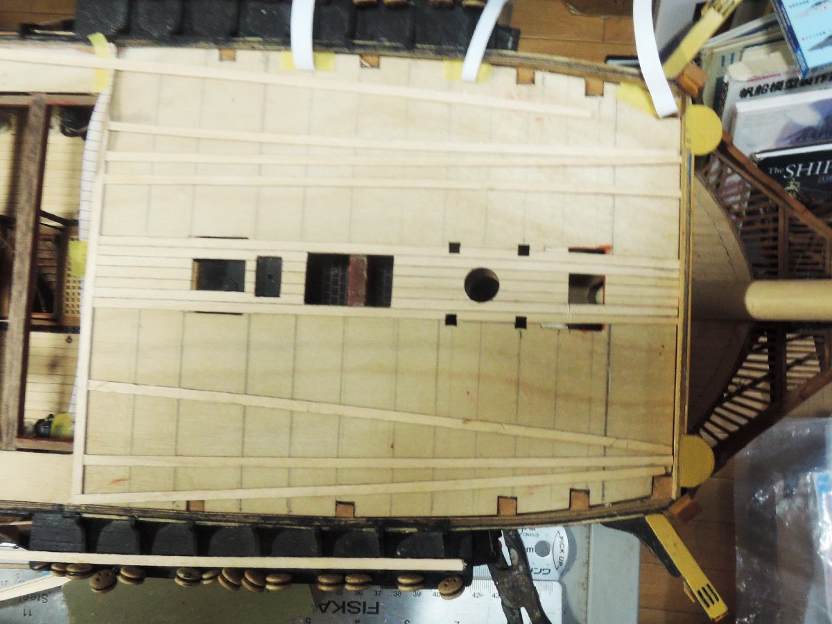
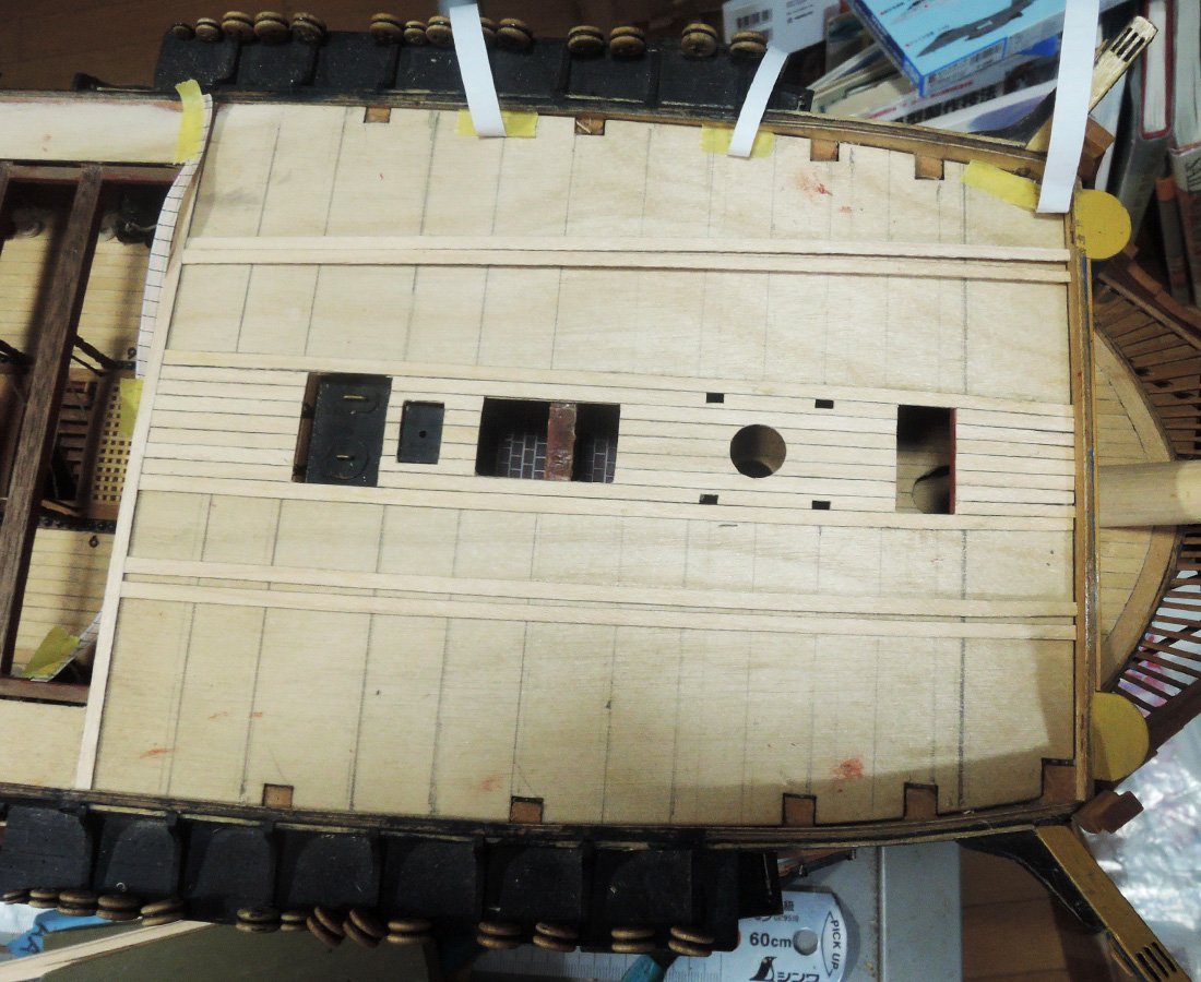
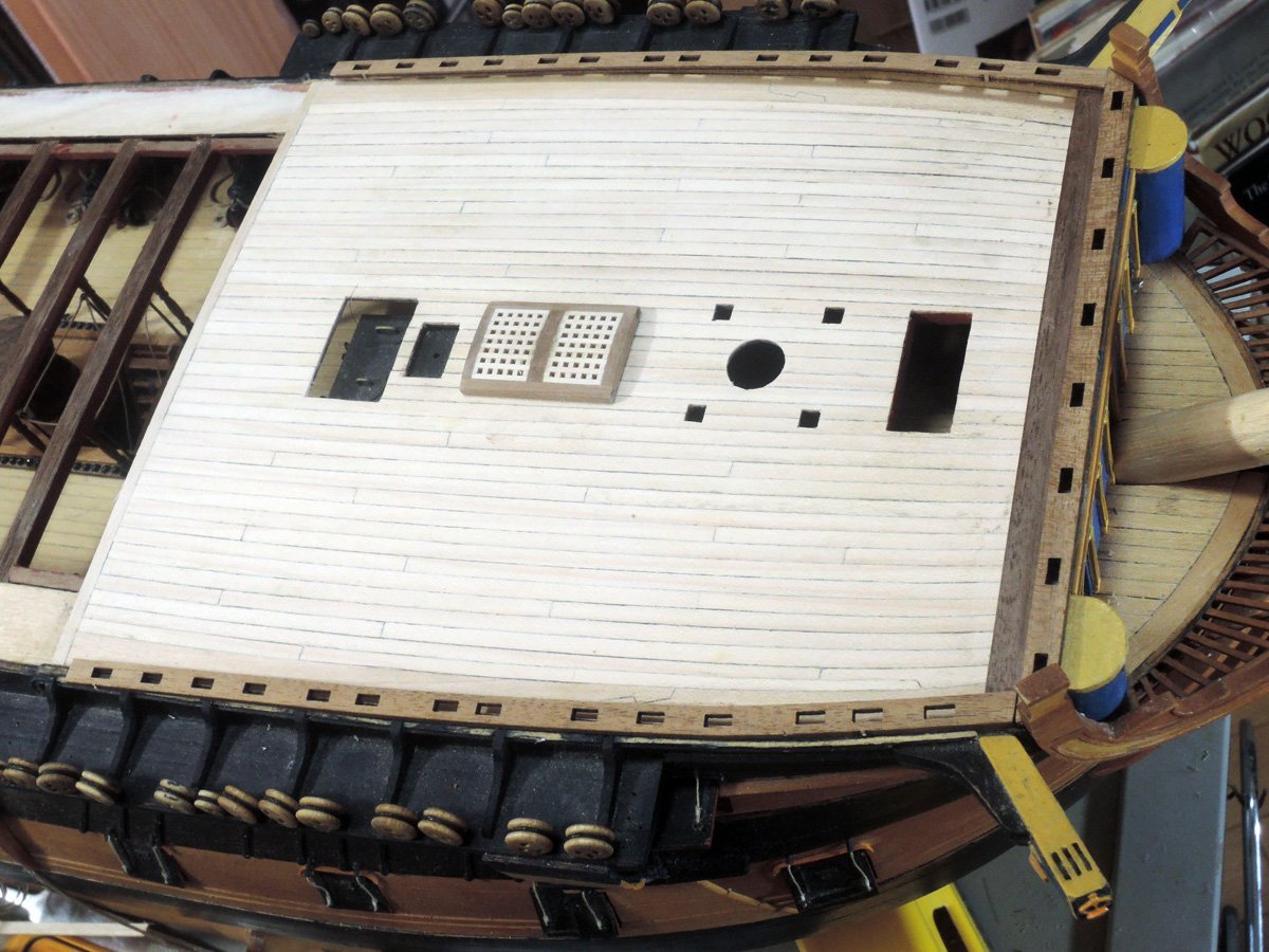
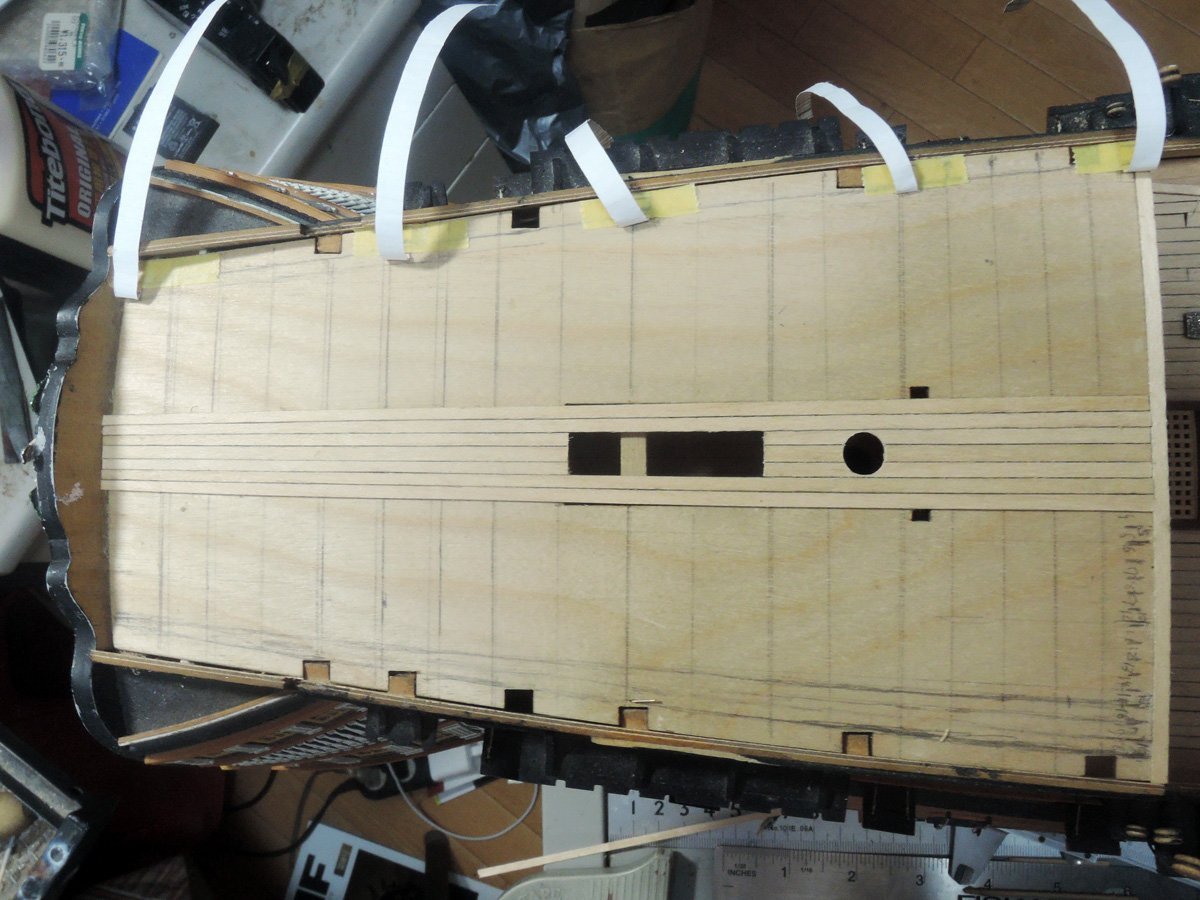
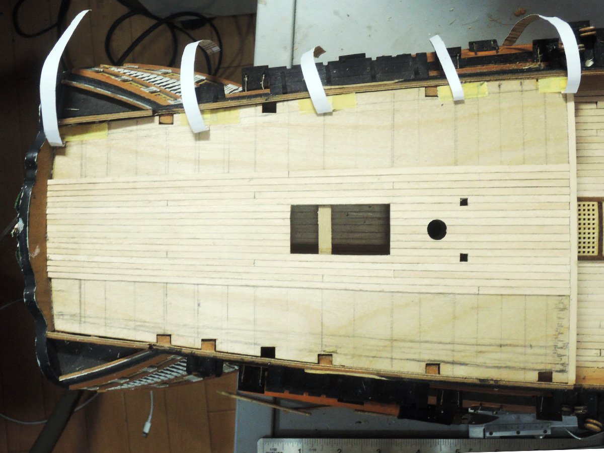
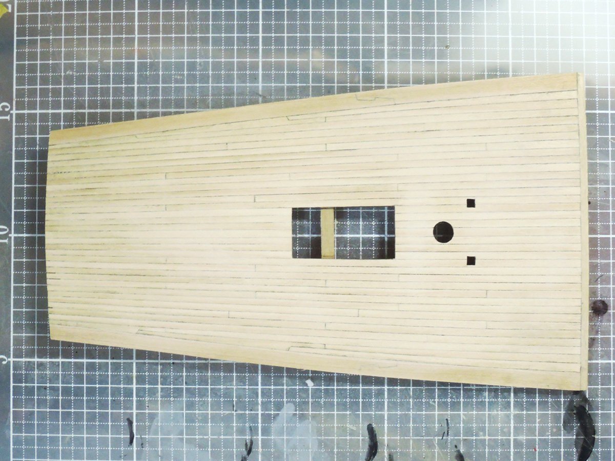
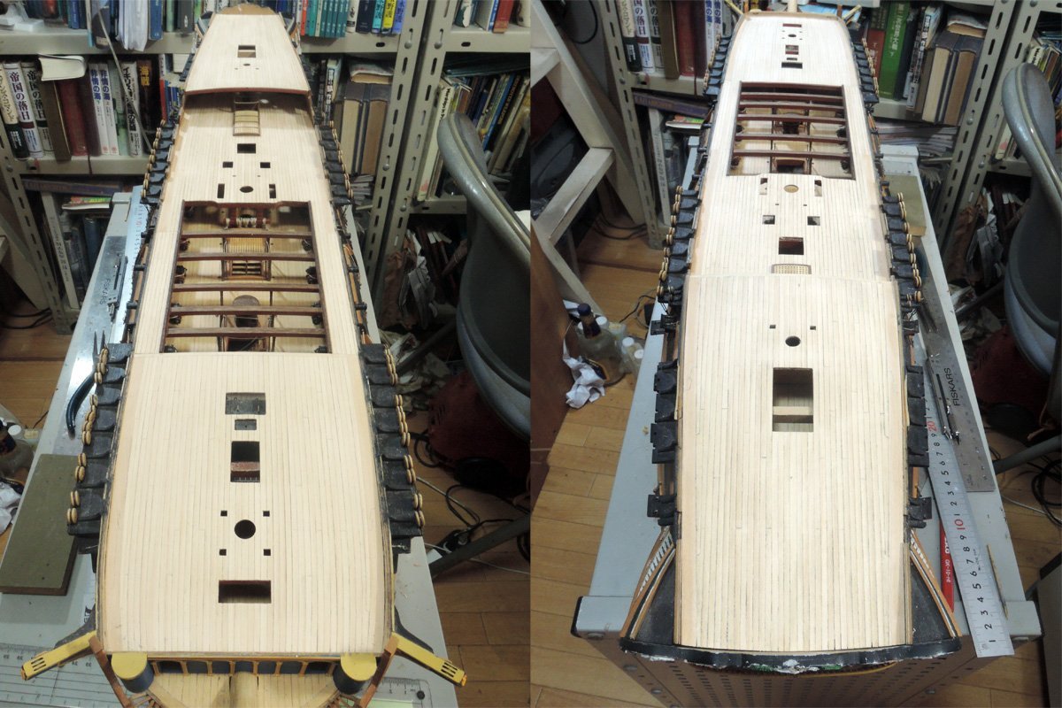
Weatherdecks planking
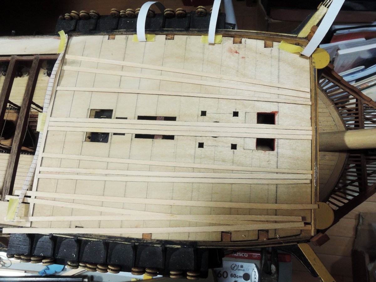
As I wrote previously, deck planking tapering and curving toward both ends is what I want to represent. It was very tedious work to decrease widths of each plank at various stations, but patience and time solve it.
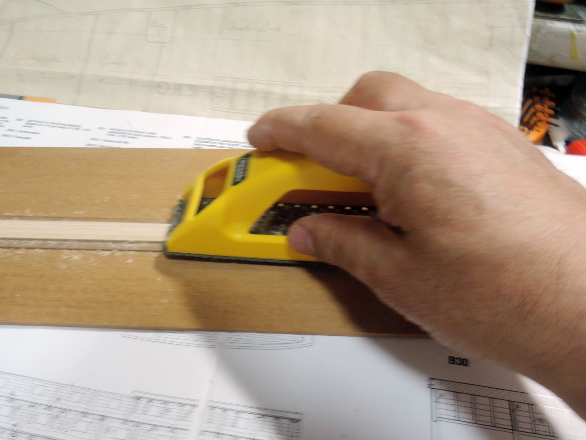
Planking material is 0.5 x 3 mm maple strips I bought from Cornwall Model Boats long ago. Although maple strips aren’t necessary supreme materials for deck planking, they are easily available, and their bright colours are quite acceptable to my eyes. Their widths are varying one by one, but I can select widest one as king’s plank, although its width isn't so obvious to eyes. Also their edges are sometimes coarse but it can be resolved by careful sanding. Anyhow I prefer maple than tanganica for deck planking.
I planked according to method of 3 butt system basically. Peter Goodwin wrote 4 butt method was used for quarterdeck, but deck planking drawing on pp 46 to 47 of AOTS Bellona shows 3 butt basically and are some of butt positions are shifted against regular rule of butt system at various points. Perhaps regular 3 butt or 4 butt system is aesthetically appropriate as model, I tried representing butt system which is out of regular rule.
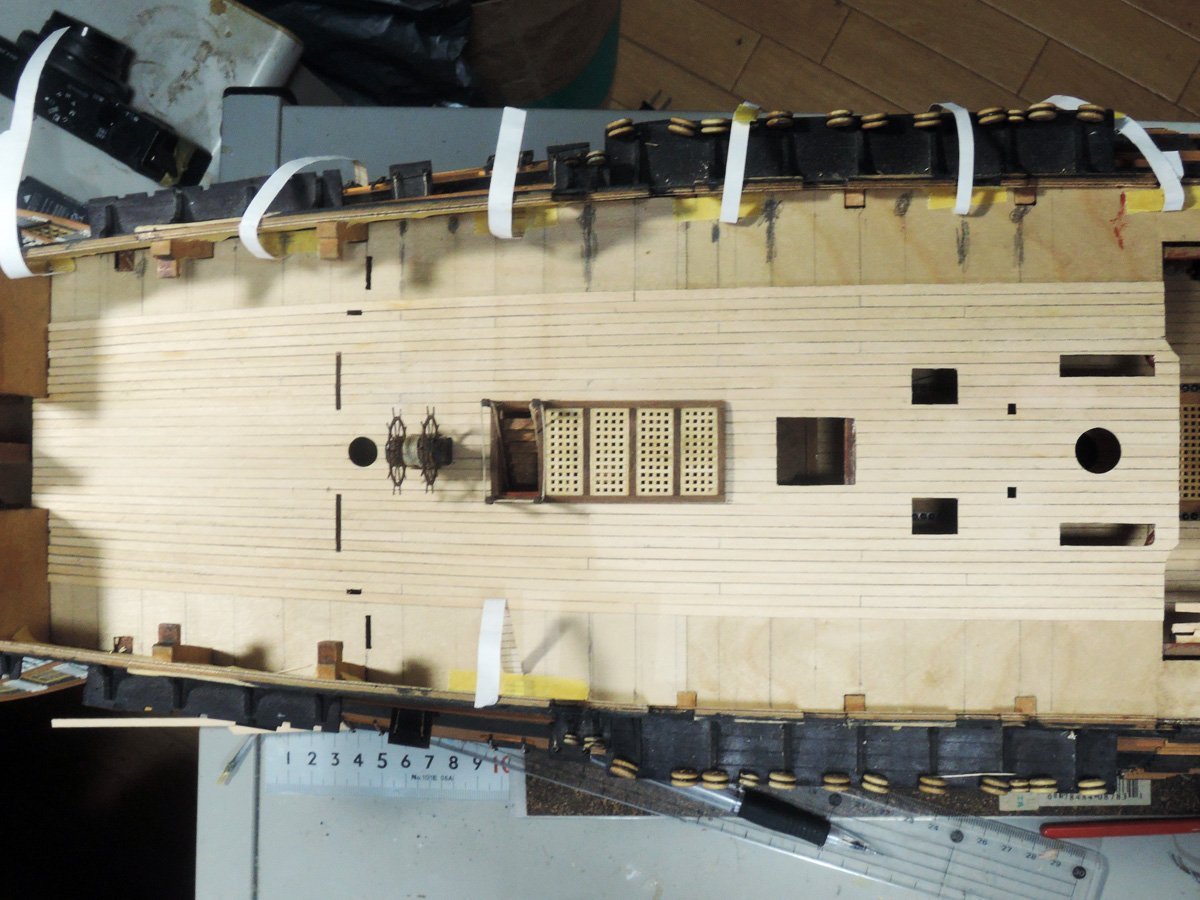
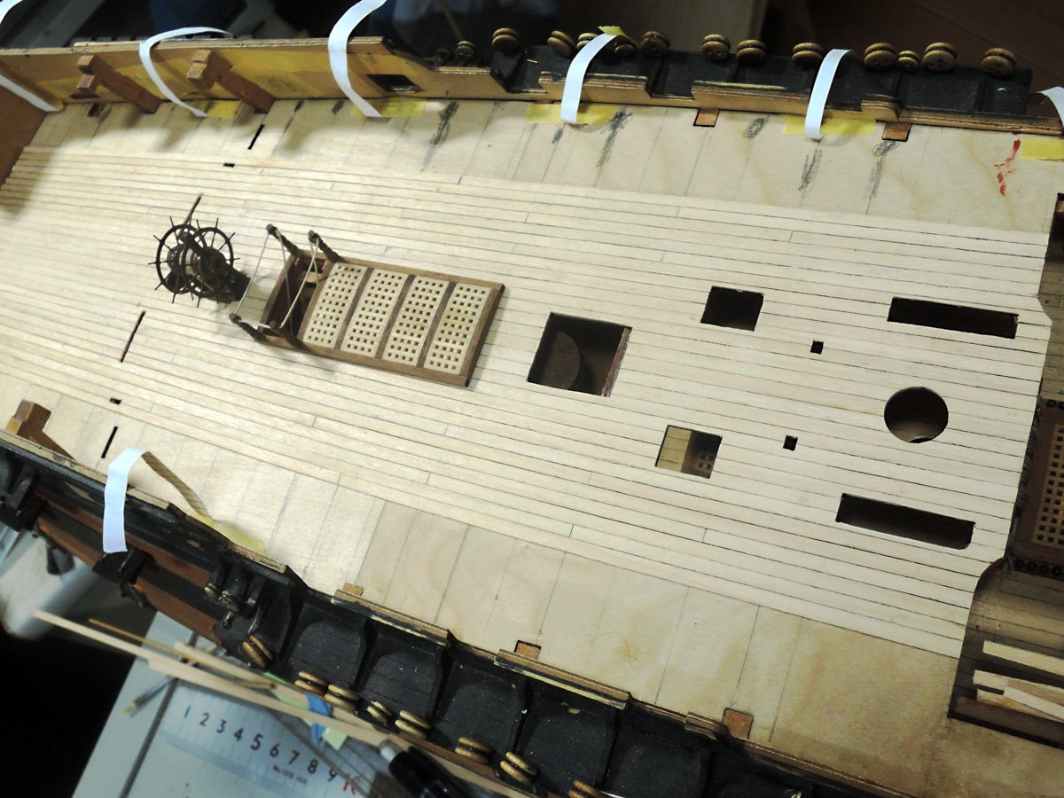
When planking is closing outer edge of deck, I cut margin plank from maple sheet. My maple sheet show sign of times comparing maple strips, but I accept it as contrast between normal planks and margin plank. Another set of deck planking plan are printed, then temporary stack to maple sheet and cut alongside of lines of planking plan. Then I engraved dummy scarf at some point. Scarf joint positions are determined to not hidden by guns.
After glued margin planks onto deck edge, I filled rest of area with representation of hooked planking. They were shaped little by little repeating dry fitting on their positions.
Fo'c'sle deck is also planked in same way.
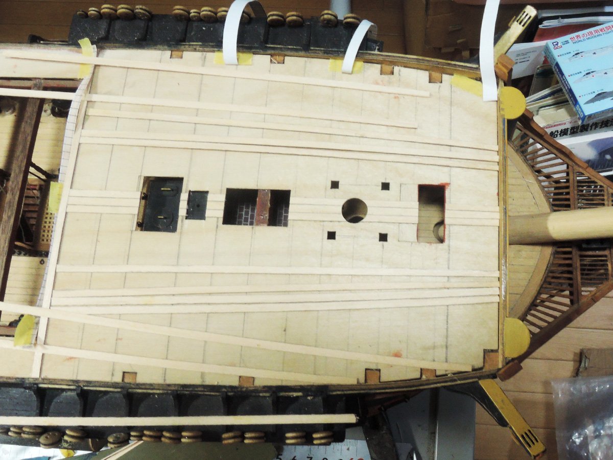
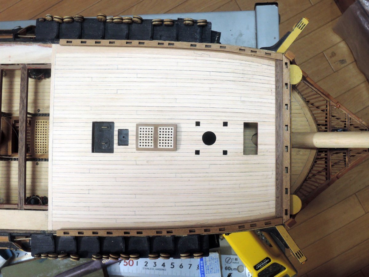
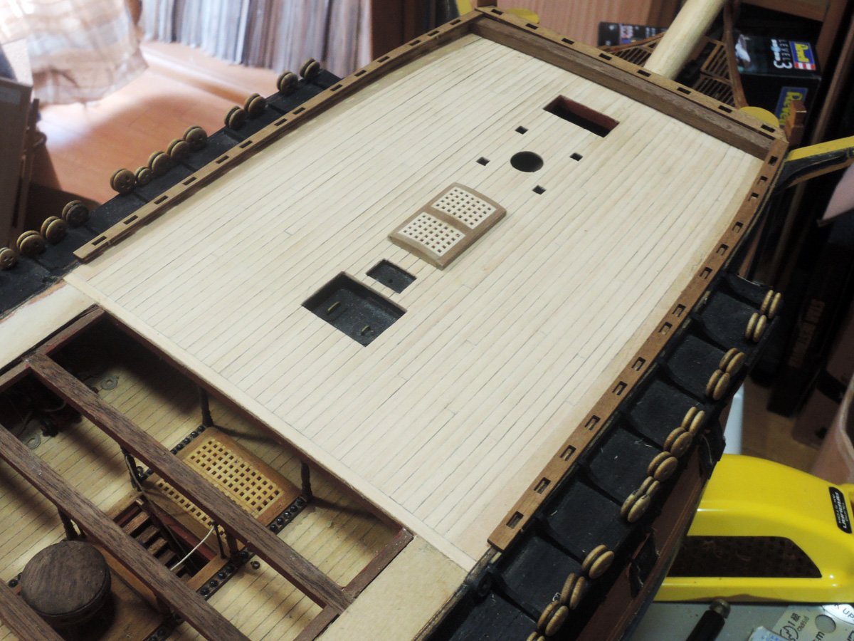
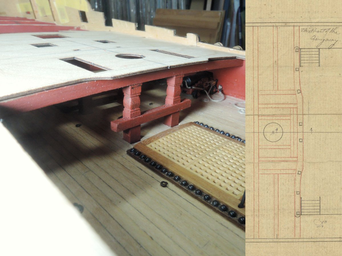
Method of gangway planking is also source of trouble of determination. Victory today shows continuous gangway planking from fo’c’sle deck to quarterdeck, but I believe this is later method. Finally I decided to represent gangway as separate structure between fo’c’sle deck and quarterdeck. I positioned forward end of “Fixed part of the gangway” at slightly forward than Elephant plan to adjust it on aftermost skid beam I previously fitted.
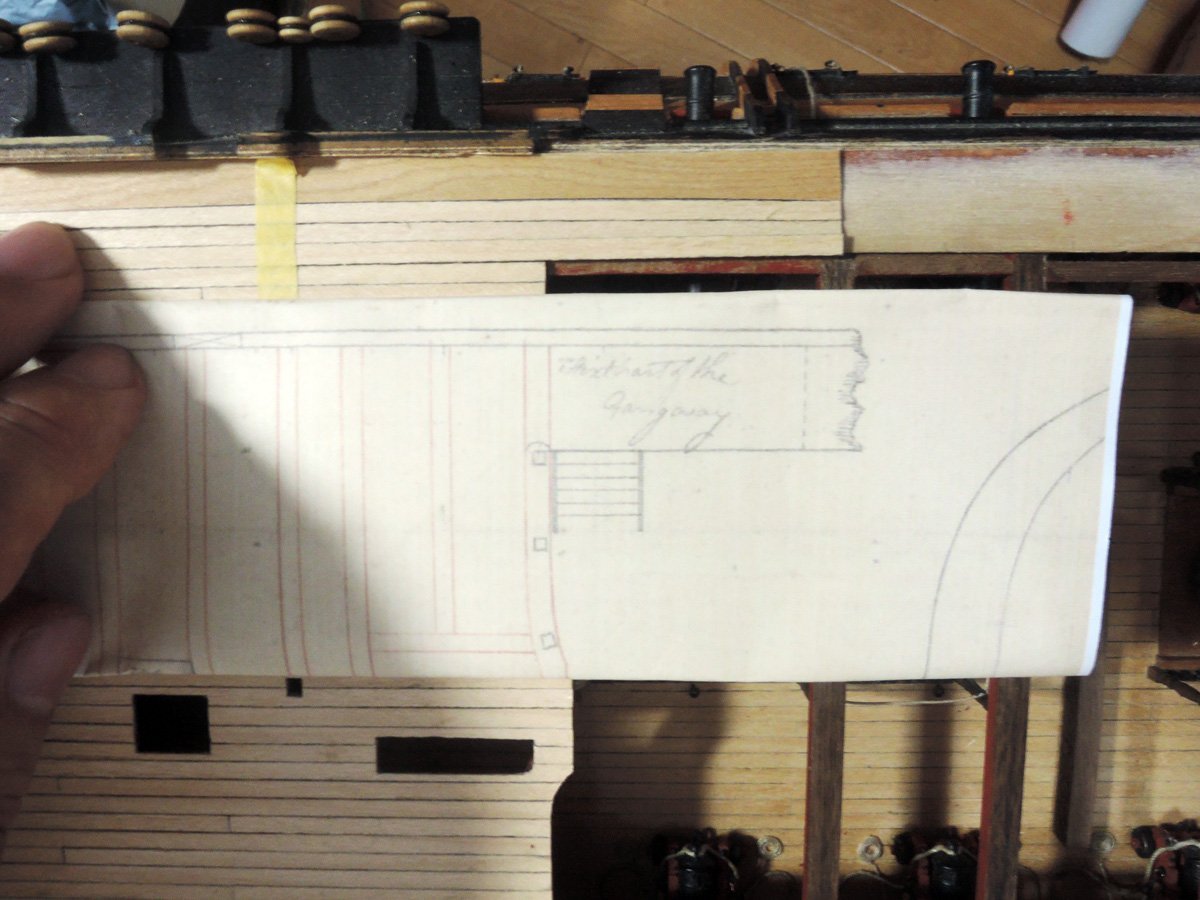
This was also questionable point, but NMM model of 74 gun ship which is related to Turkey around 1800 shows fairly long fixed part of the gangway.
https://collections.rmg.co.uk/collections/objects/66611.html
I was encouraged by this model and adjusted forward end of fixed part slightly longer forward than Elephant plan. Also I slightly enlarged inner edge of gangway according to depiction of Goodwin. Maybe widened gangway is matching to permanent skid beams.
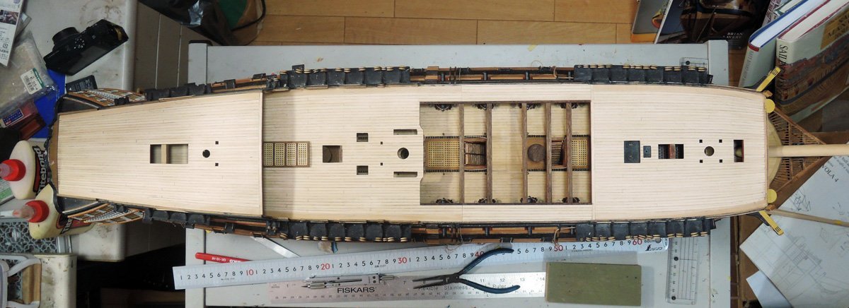
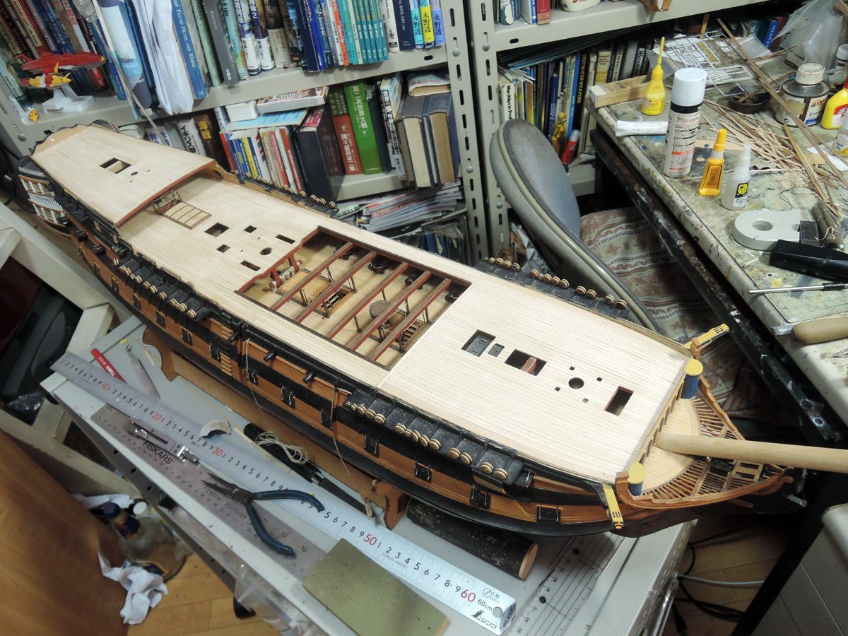
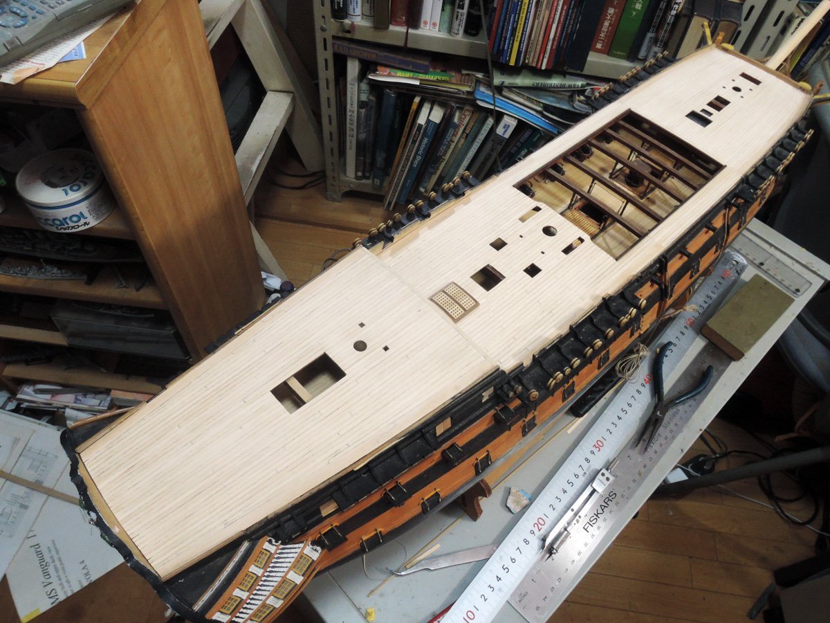
I also planked poop deck at this point while I’m remembering experience of quarterdeck and fo’c’sle deck. Major difference is that poop deck baseboard is temporary dry fitted, not glued to its position because I wanted to plank poop deck at the situation baseboard is cambered.
When planking is closing to deck edge, I removed poop deck and glues last of hooked planks and margin plank. This time margin plank is glued at last stage. Inner edge of poop deck margin plank is cut according to planking plan, but outer edge is roughly cut, and cut to correct shape after glued deck edge.
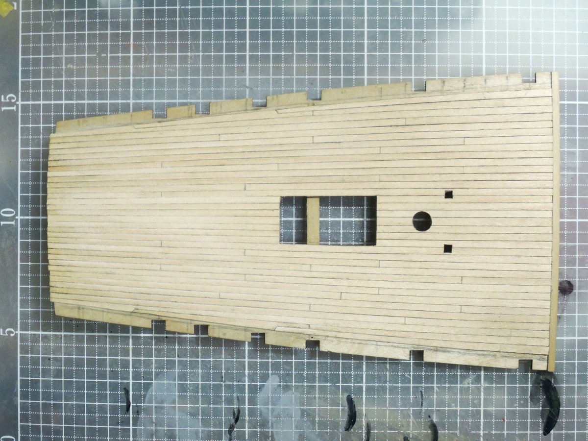
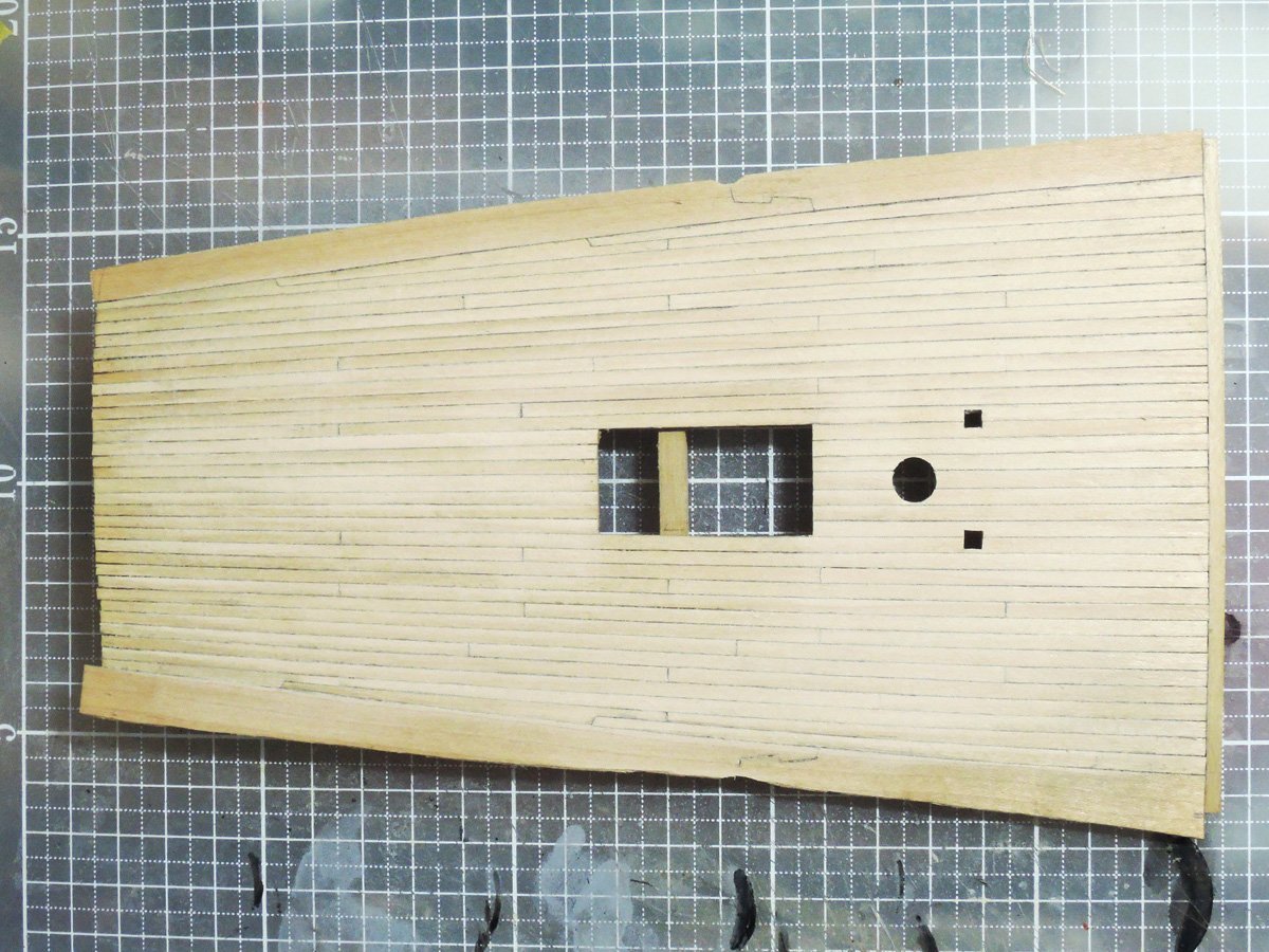
Although treenailing is not yet started, weatherdeck planking is completed at last. Widths of caulking between planks are varied because of my imperfect work, but I’m satisfied to see representation of tapering and curving of planks are fairly well done.
- mort stoll, BLACK VIKING, Wahka_est and 6 others
-
9
-
Preparation of weather decks planking
Though some of these treatments were done before, I want to tell about them here.
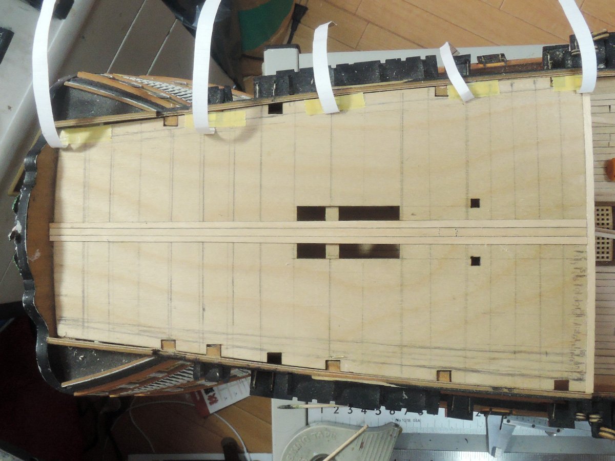
I marked beam positions onto baseboards of fo’c’sle deck and quarterdeck referring deck beam plans of Elephant. These marks will show the points where deck planks should be butted.
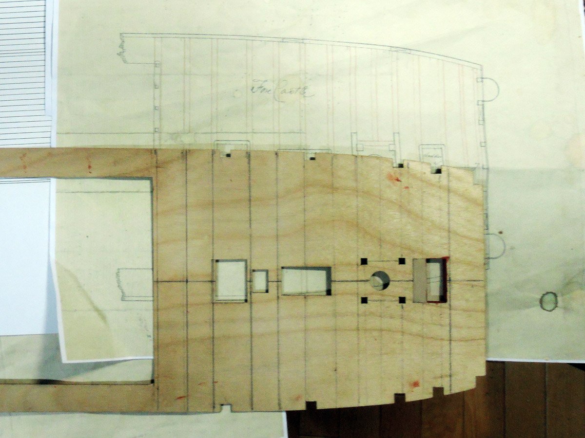
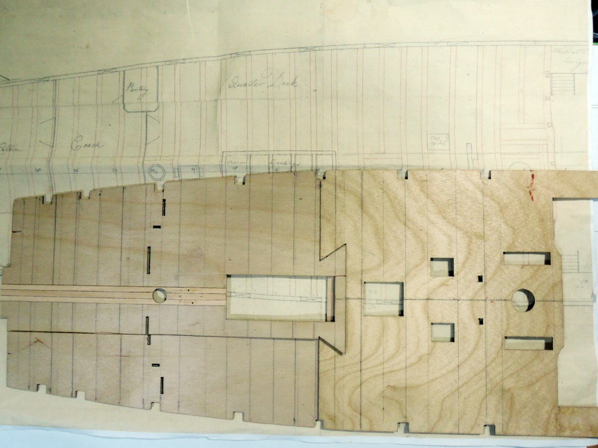
Next is preparation of weather deck planking plan.
There is fo’c’sle and quarterdeck planking plan of anonymous 74 gun ship of 1798 on pp.46 to 47 of AOTS Bellona. This plan is showing each plank is tapered and curved towards both ends.
Also outboard plank is blended into next inboard plank like drop strake of hull, instead of joggled into margin plank. Although it isn't showing those for fo'c'sle deck or quarterdeck but upper deck, plan of another anonymous 74 gun ship also shows same feature.
https://collections.rmg.co.uk/collections/objects/382650.html
I didn’t represent these features on upper deck planking because planks of both ends will be hidden by fo’c’sle deck or quarterdeck. But most of planks of weather decks can be visible except aft part of quarterdeck which is hidden by poop deck.
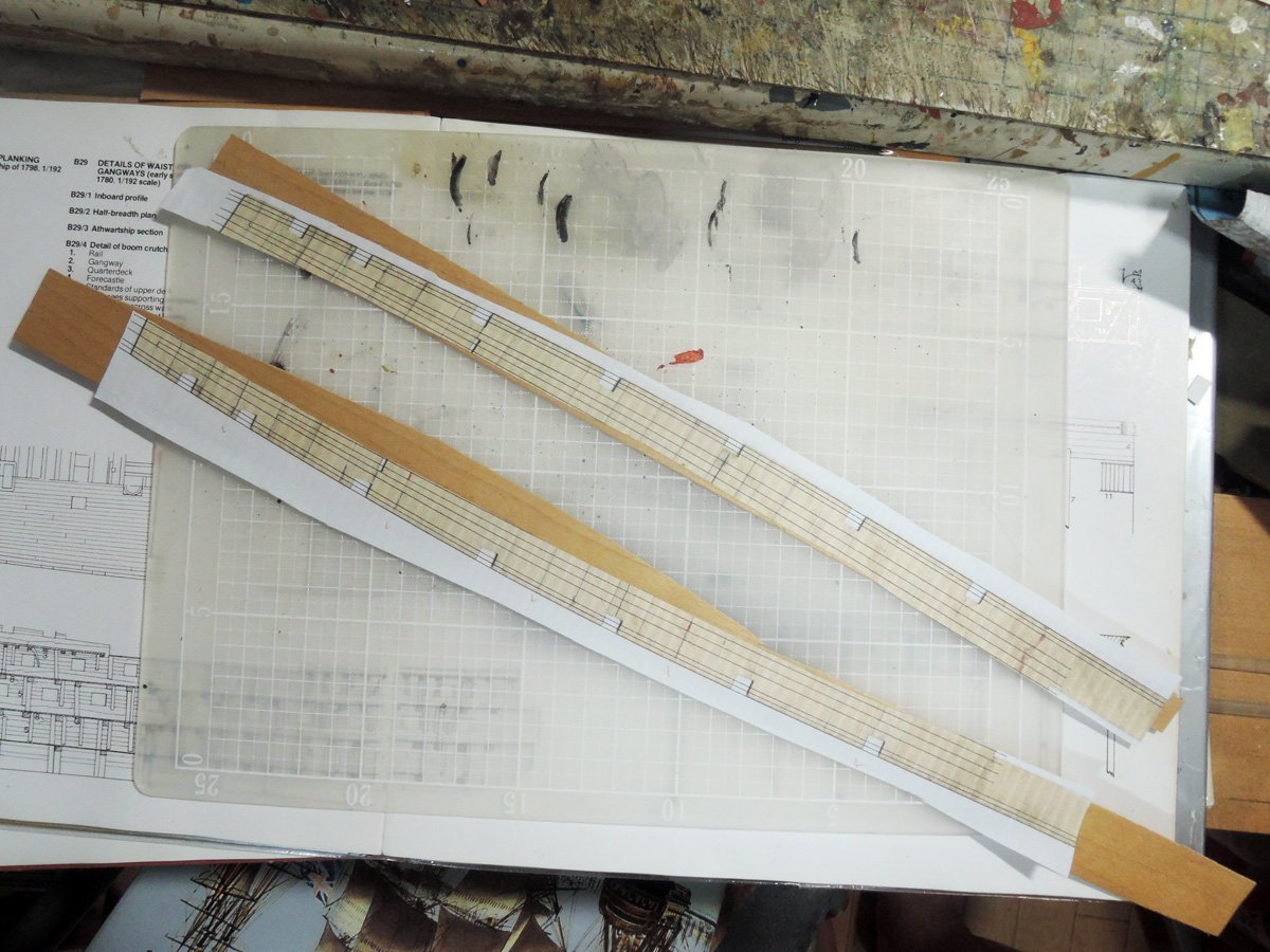
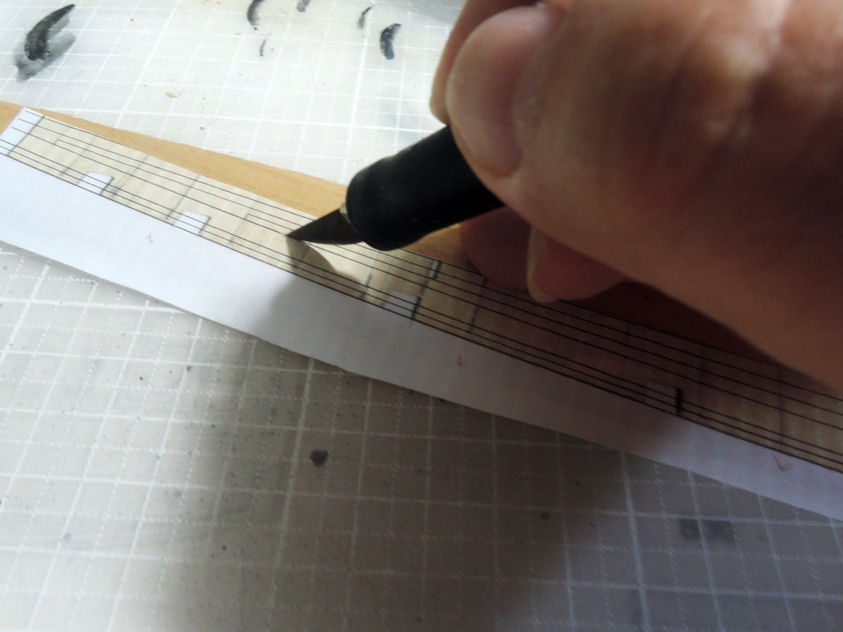
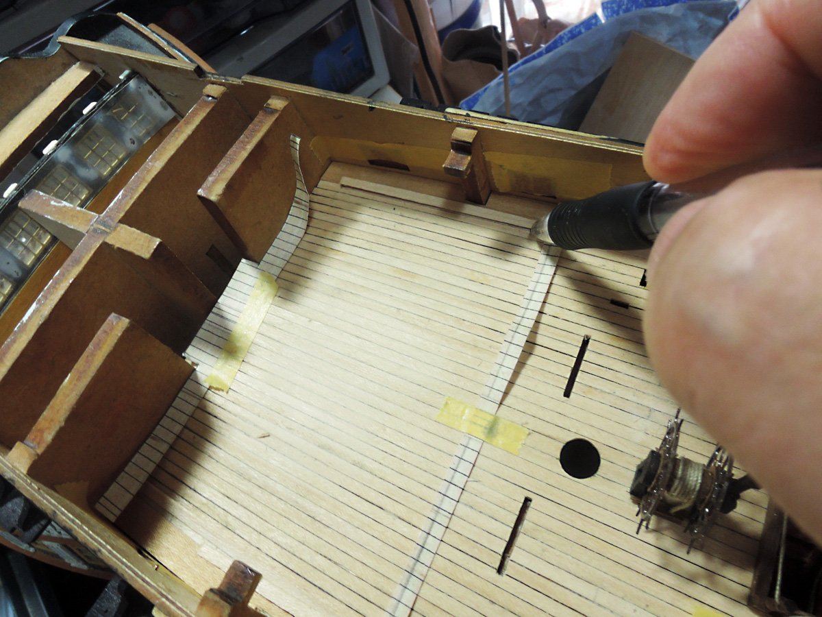
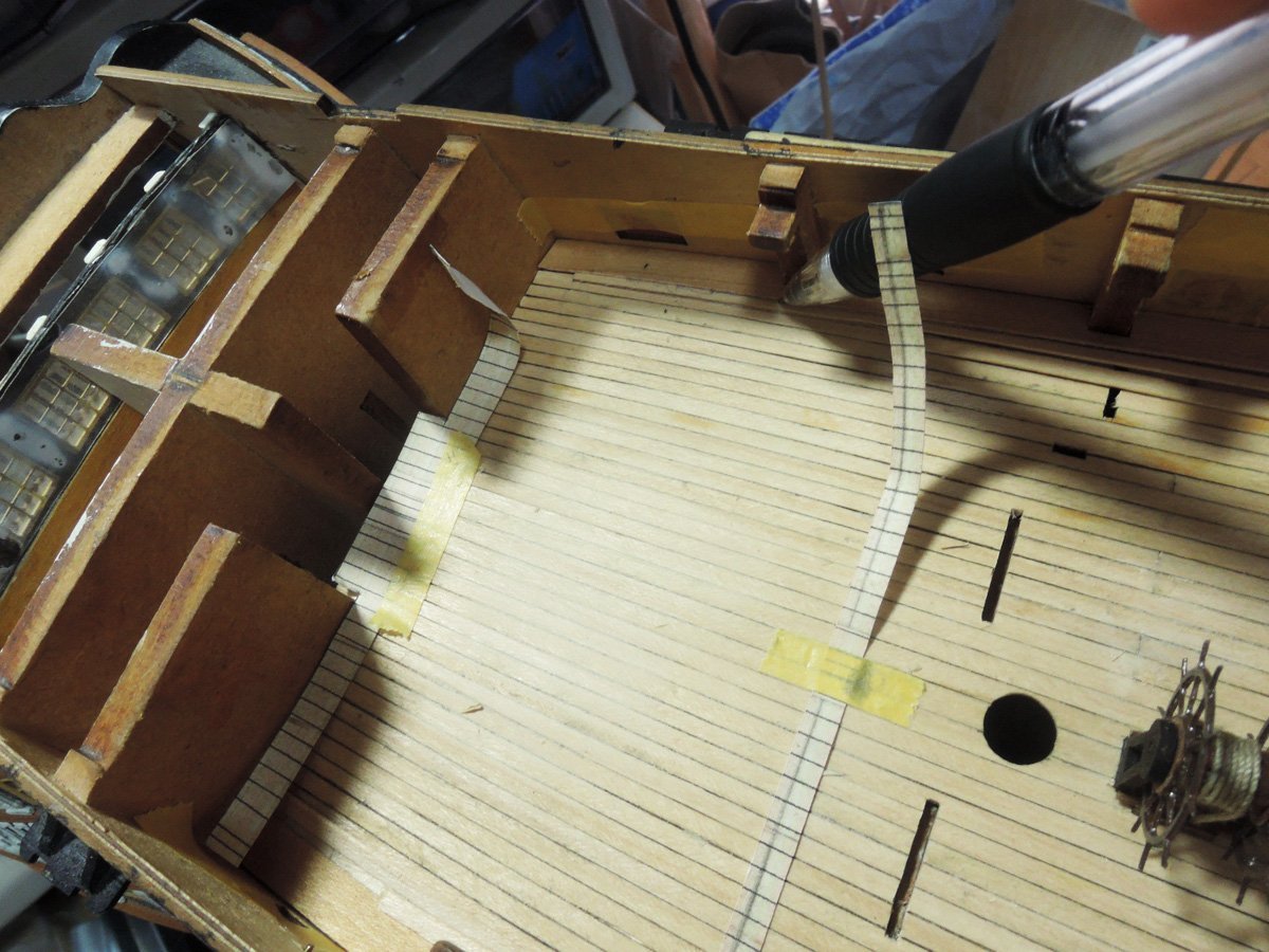
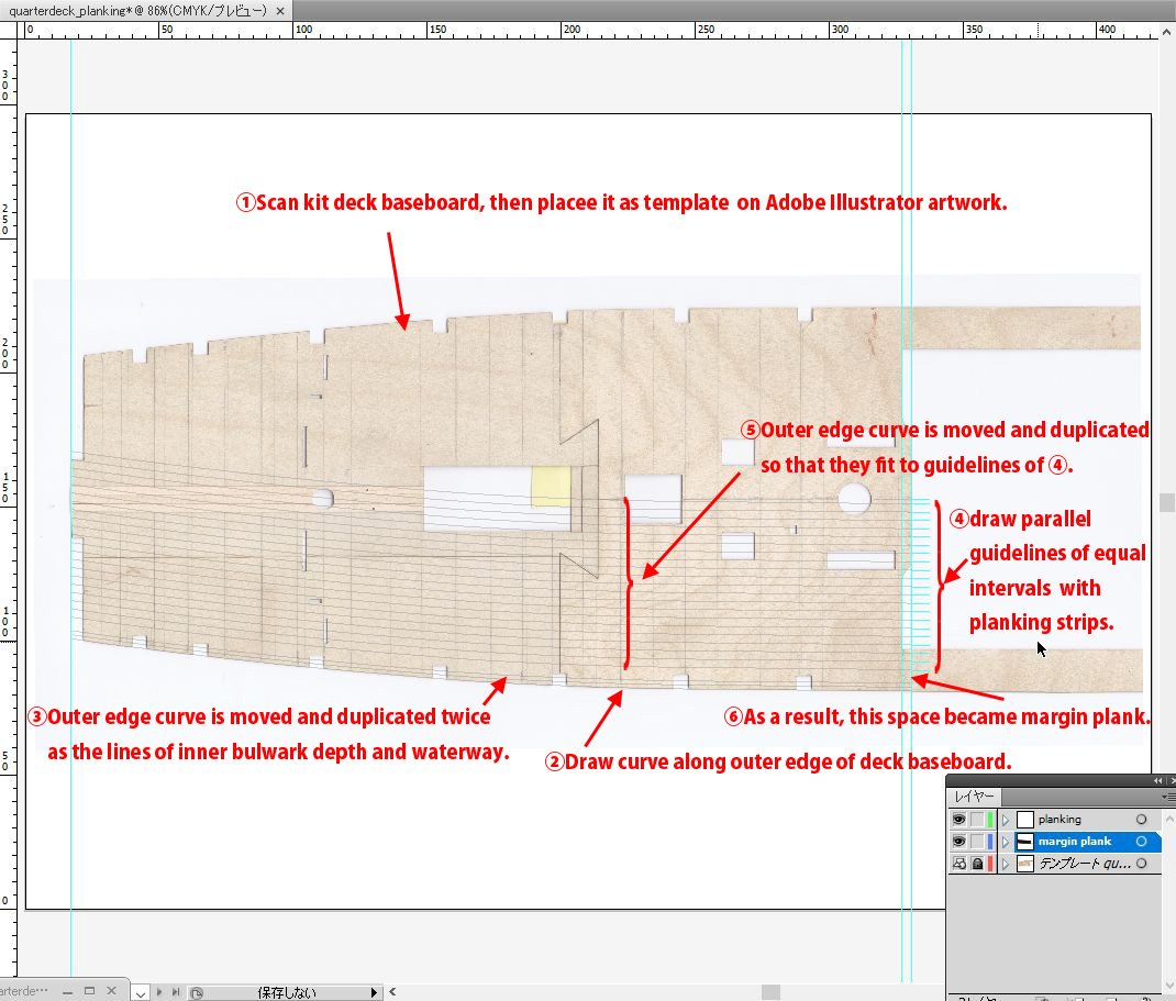
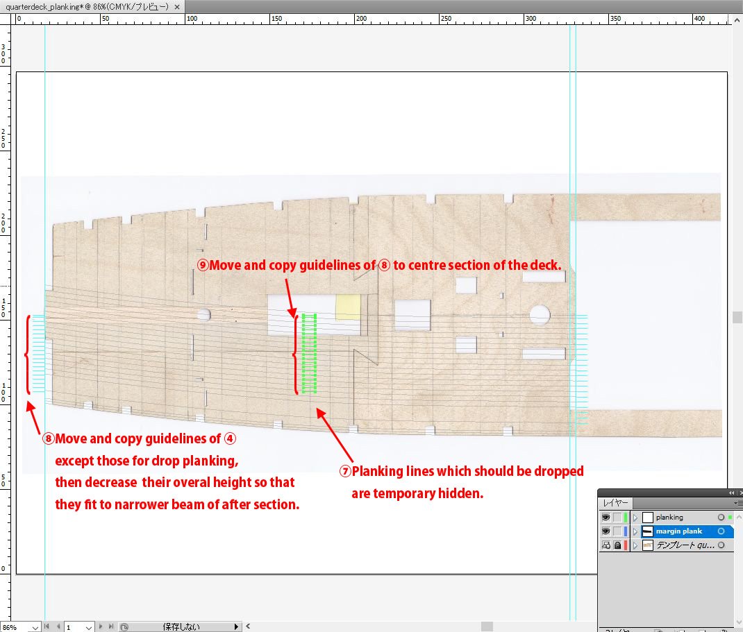
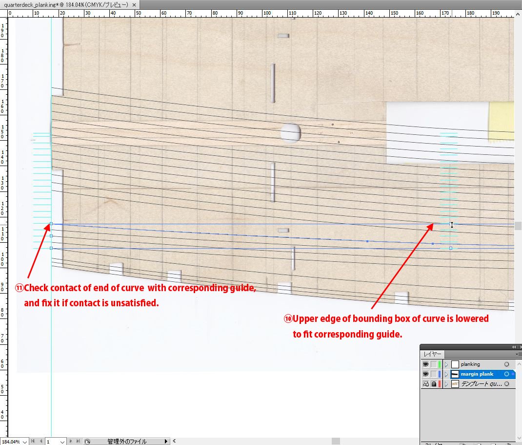
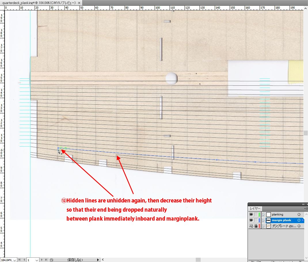
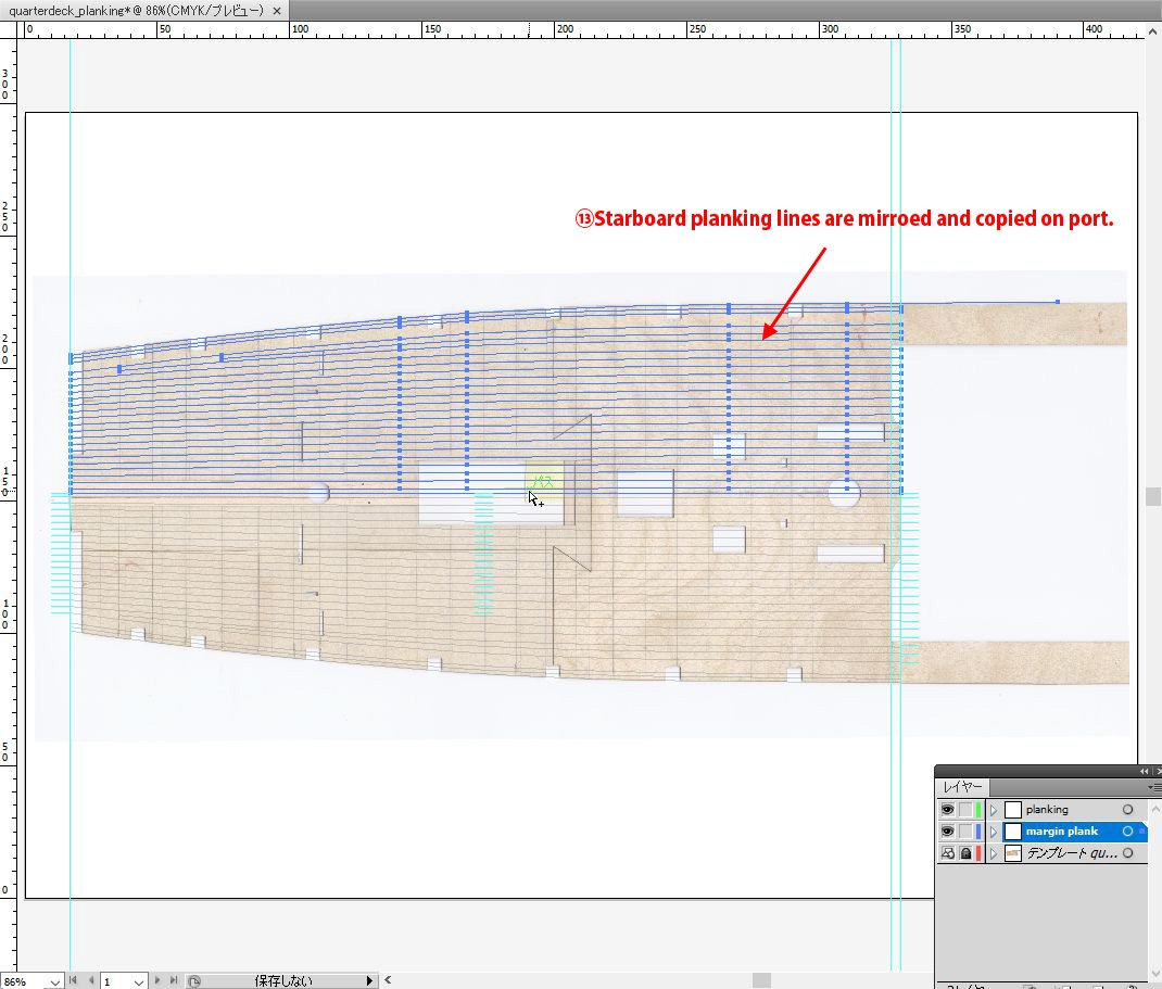
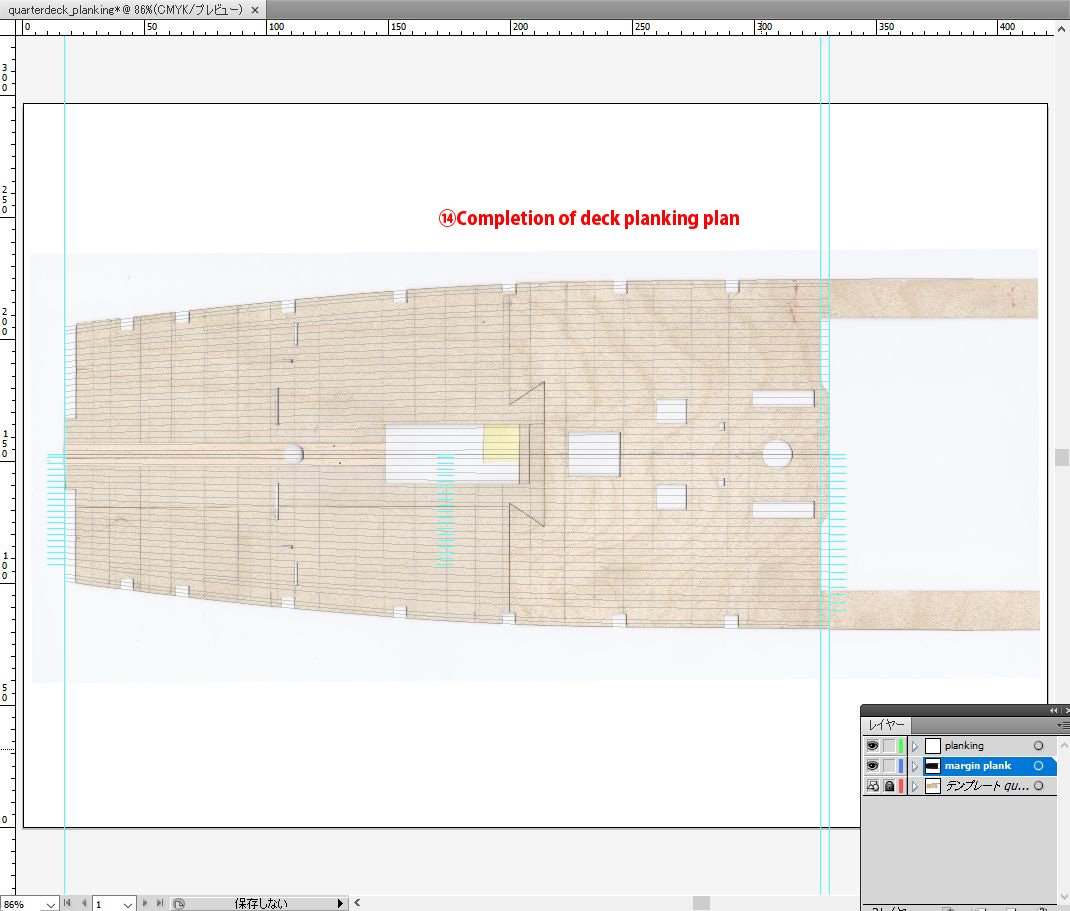
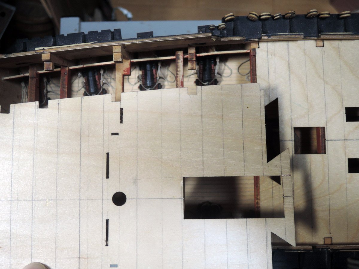
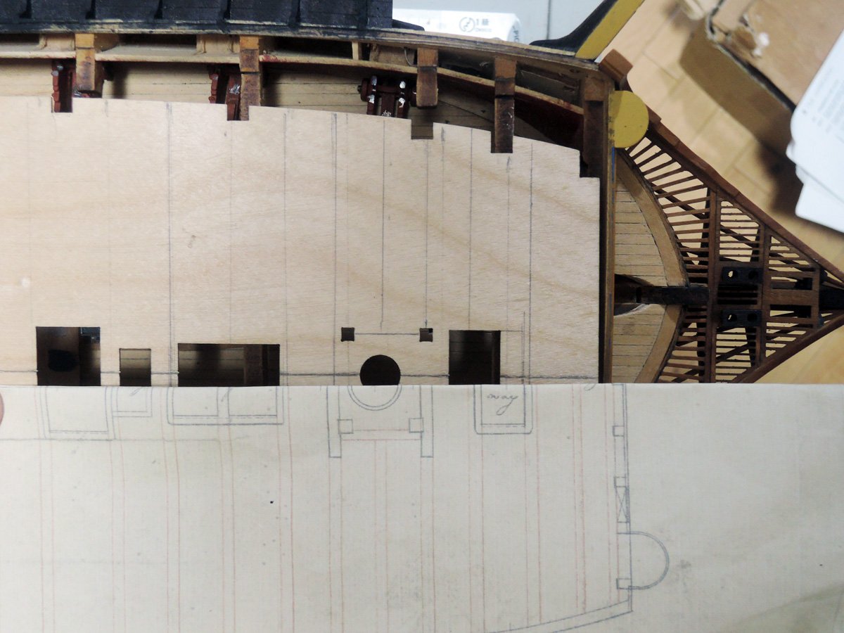
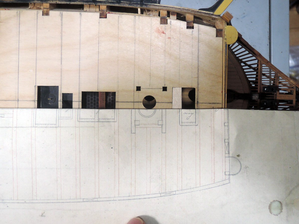
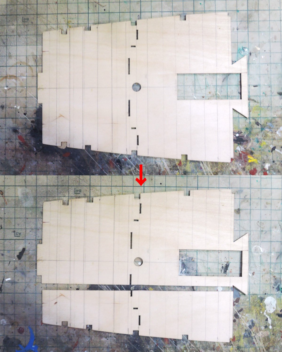
So I prepared deck planking plan with Adobe Illustrator.
Below images are sequence how I draw planking line of quarterdeck. Plan for fo’c’sle deck is also drawn in same way. I only hope images below will be help for readers to understand how I drew these lines.
Poop deck is also treated as I did for fo’c’sle deck and quarterdeck except beam positions are referred to inboard profile of Elephant because Elephant deck beam plan isn’t containing that for poop deck.
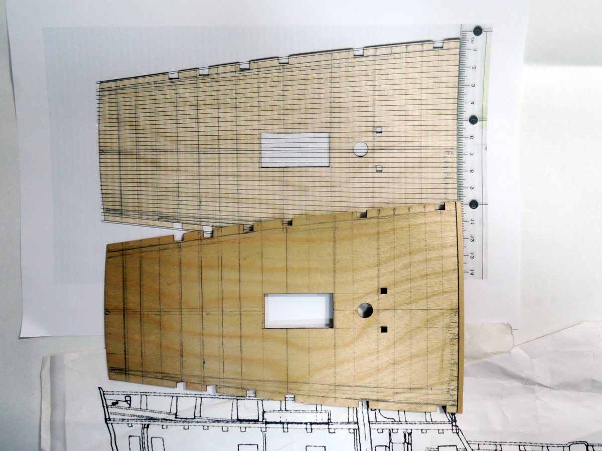
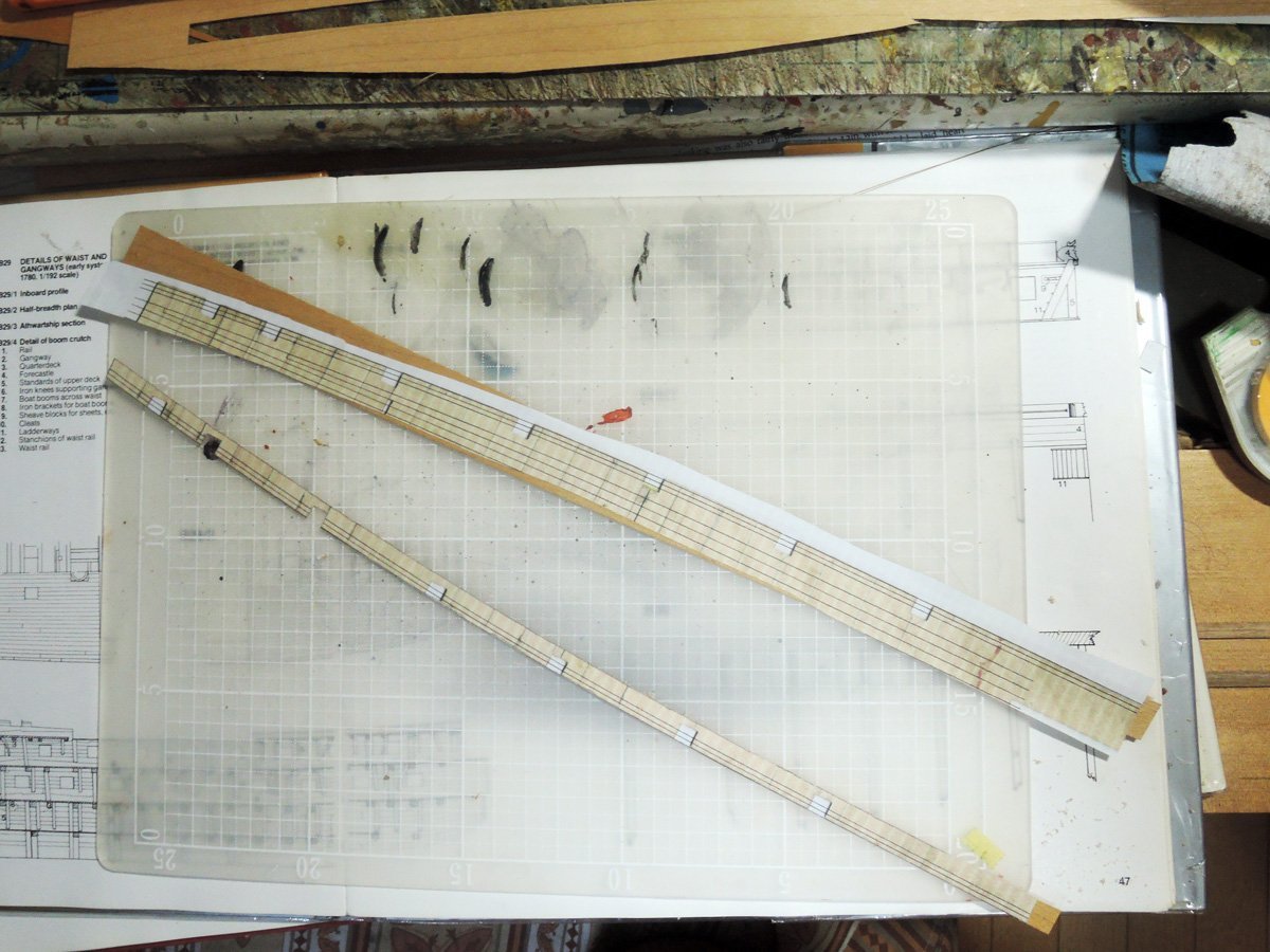
Finished planking plan are then printed. I printed two sheets of each deck planking plan. One sheet will be used for general reference when I plank each deck.
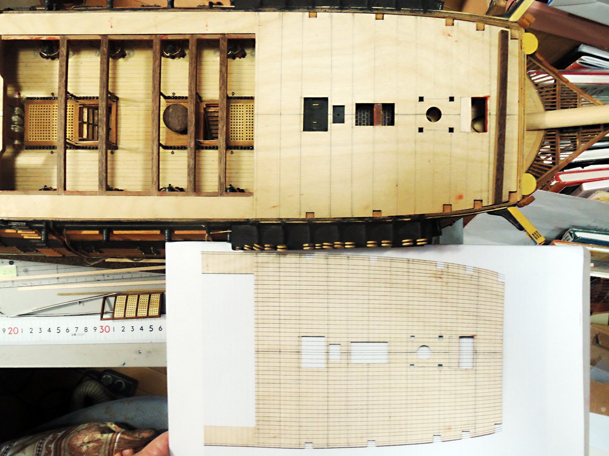
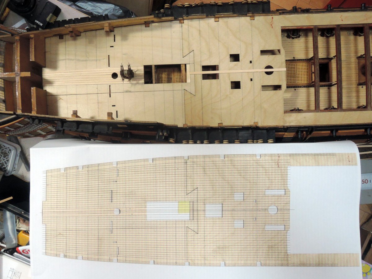
Another sheet is cut into several sections at beam positions and temporary stuck on deck baseboard edge as guide for checking each plank width.
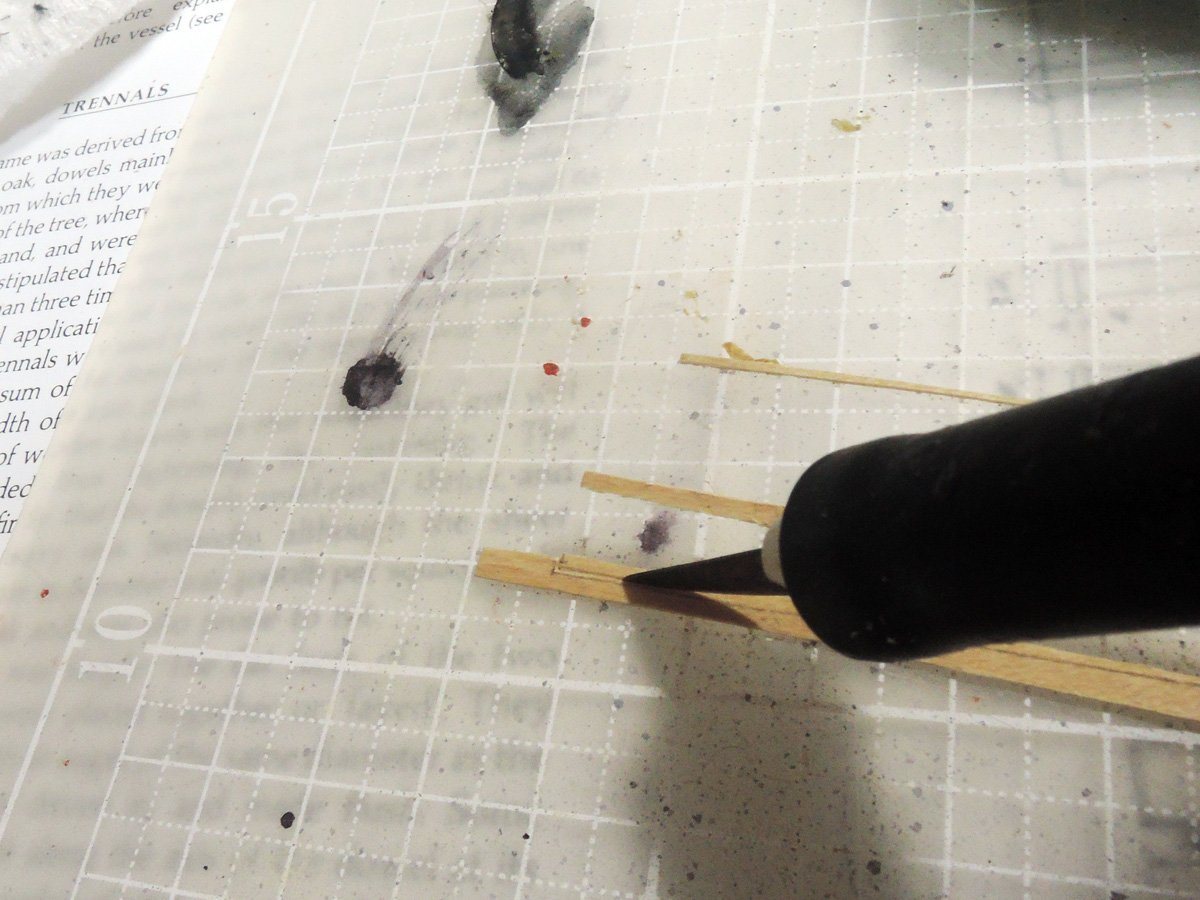
Planks are set into simple holder I made from surplus woods. I tapered 20 planks at once with help of this holder.
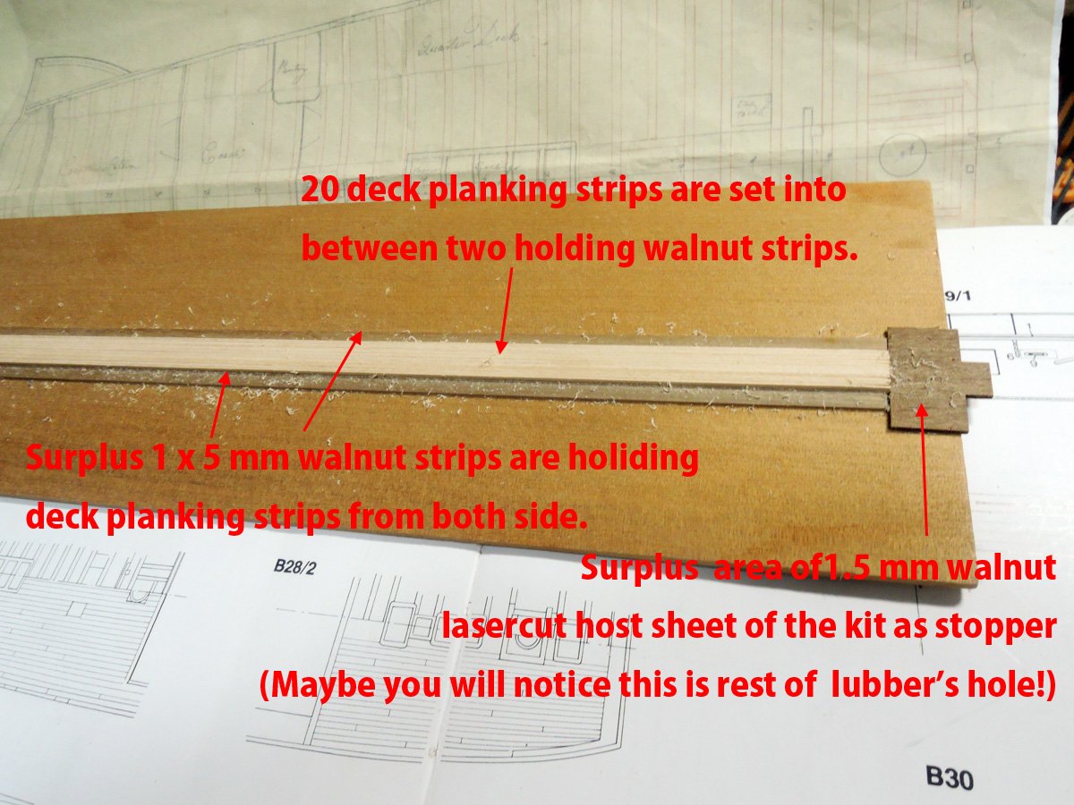
Actually planks should be bent sideways as they are going to outboard. They will be bent with help of heat and steam from kettle.
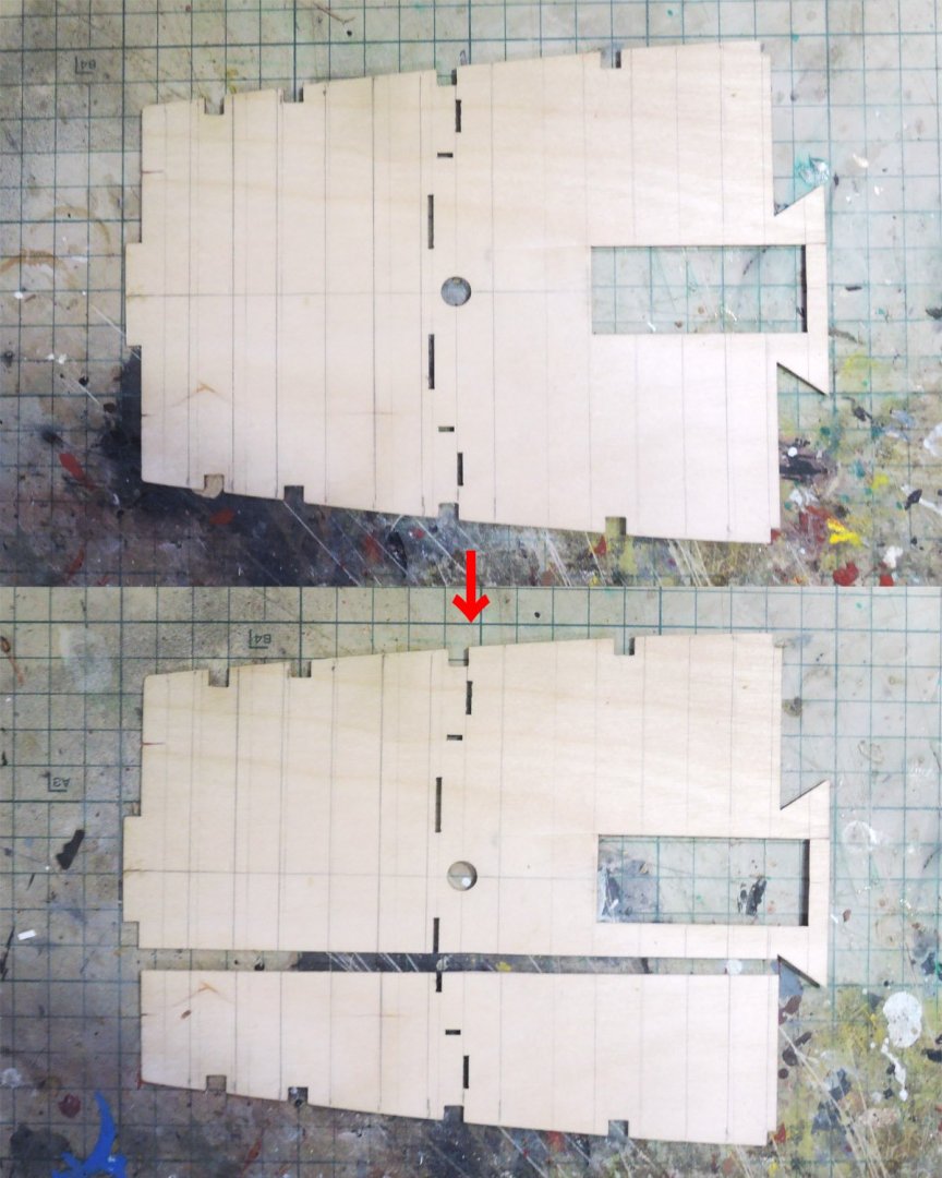
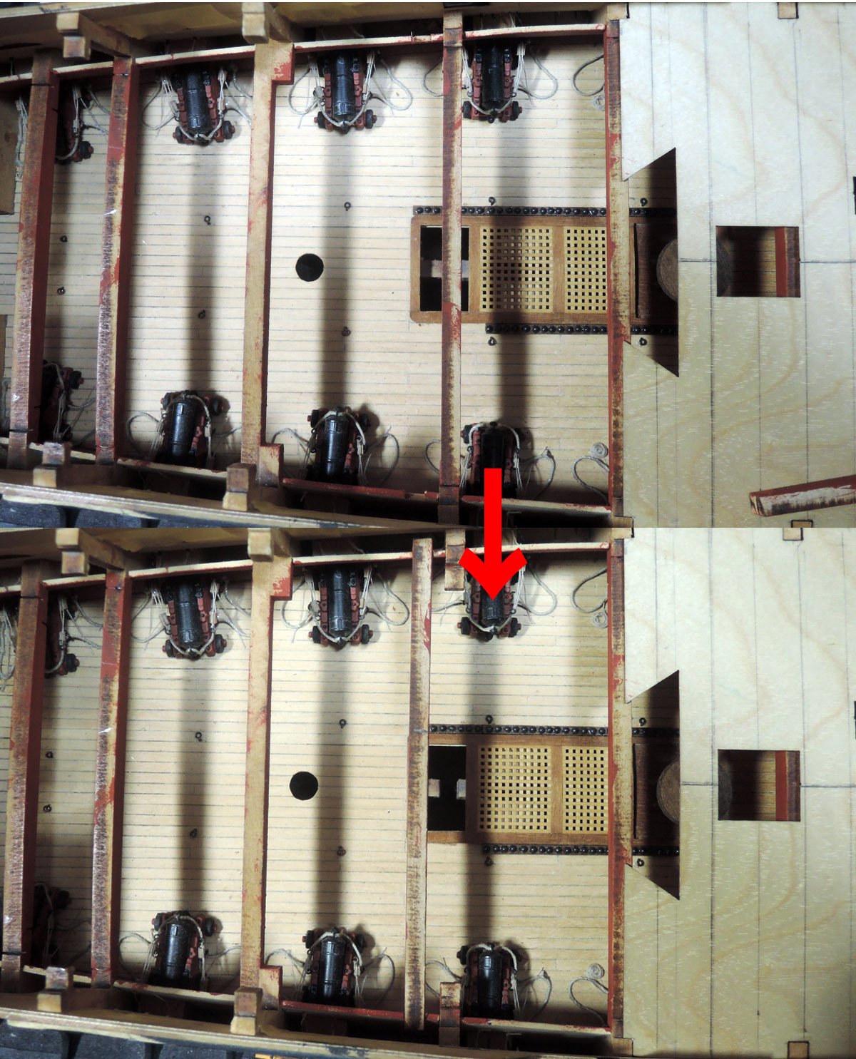
After these preparations were done, I started planking of quarterdeck. As posted before I split quarterdeck baseboard at slightly starboard area of hatch opening.

Firstly I only glued port baseboard and starboard baseboard wasn’t glued at this point.
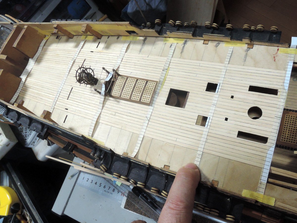
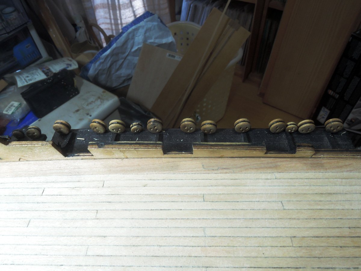
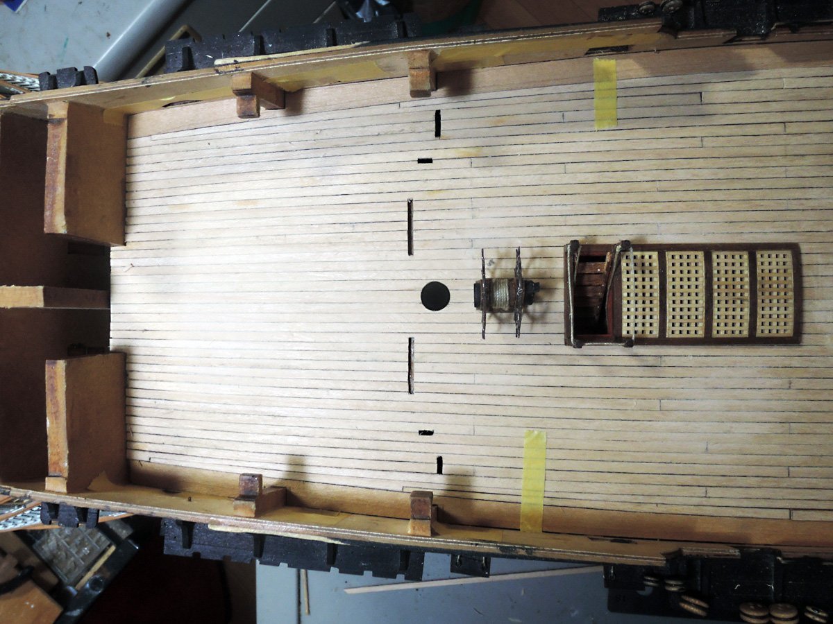
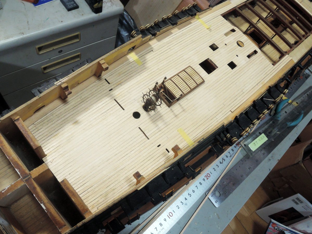
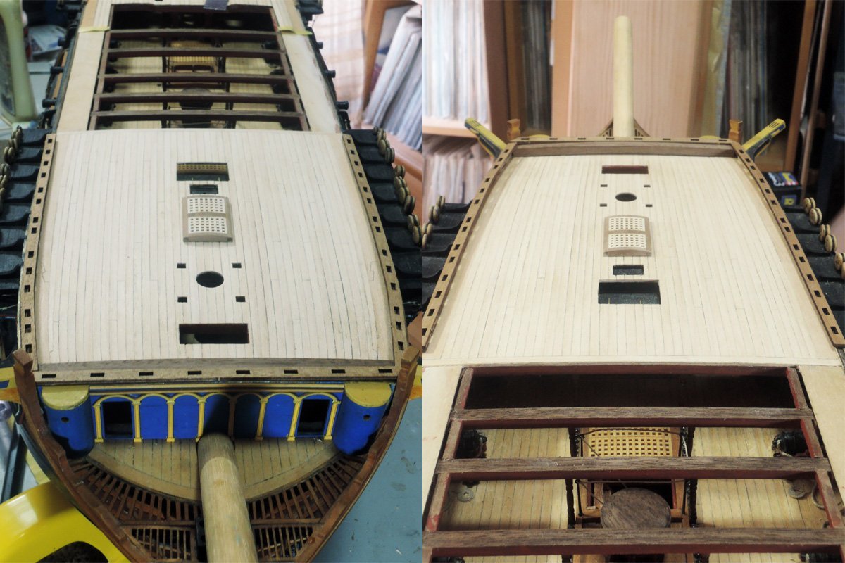
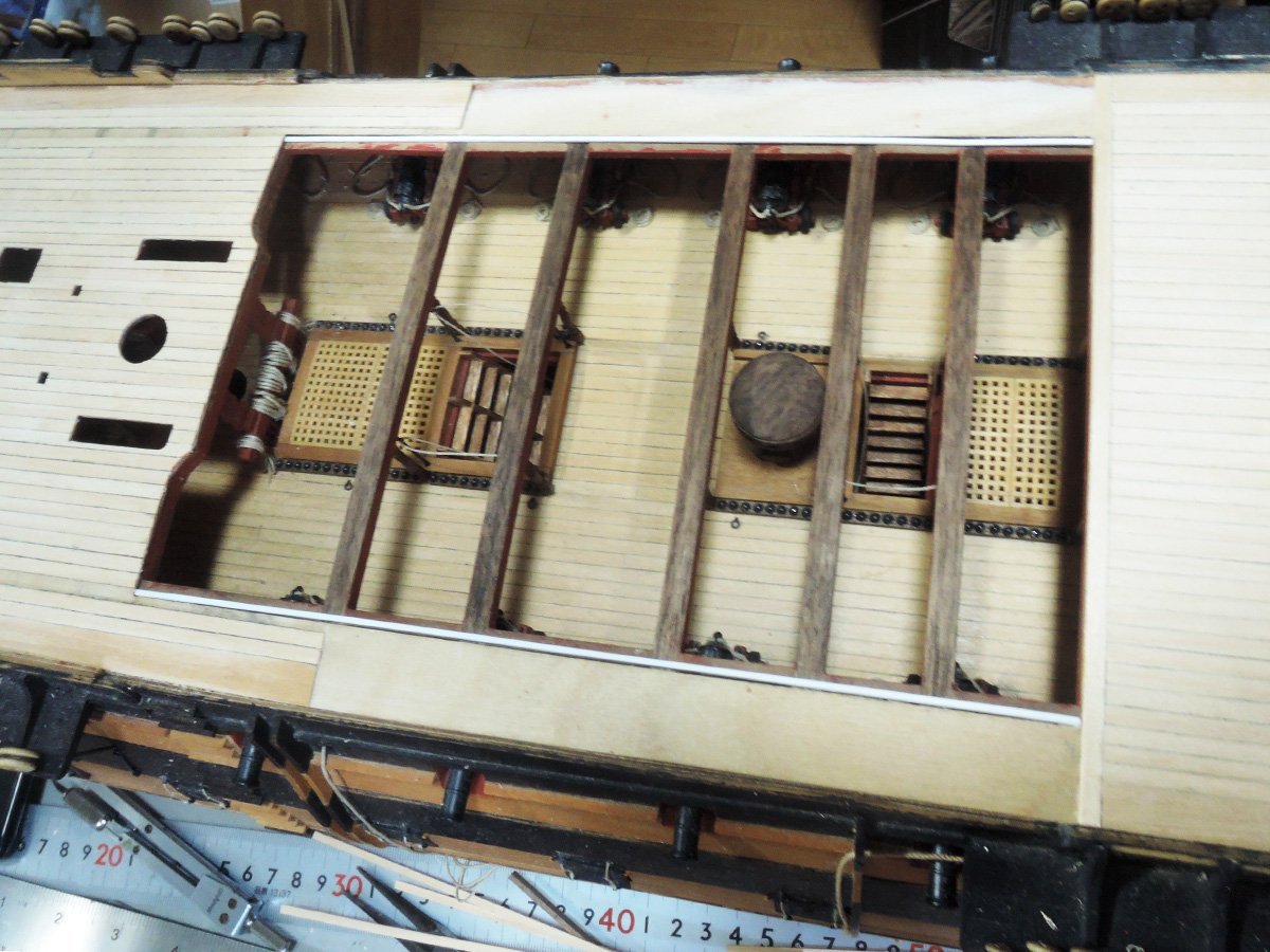
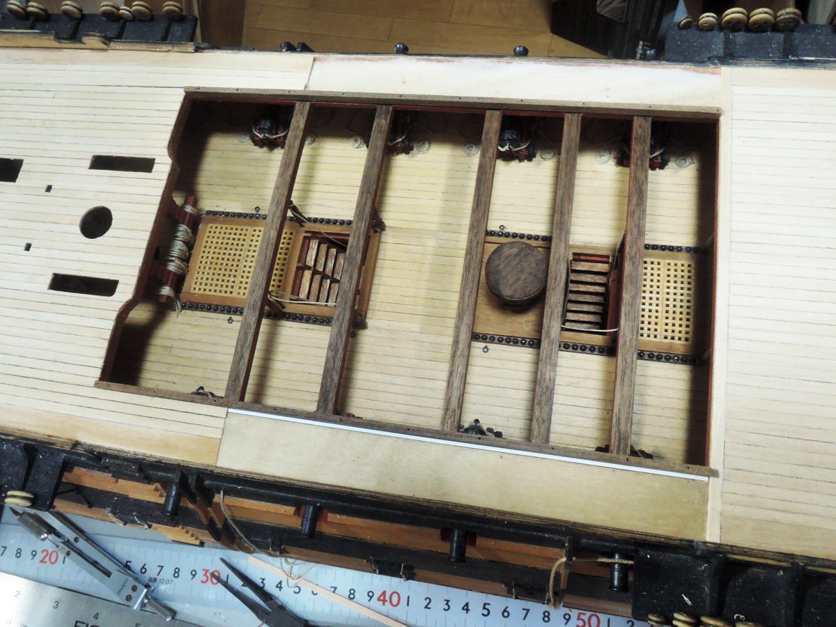
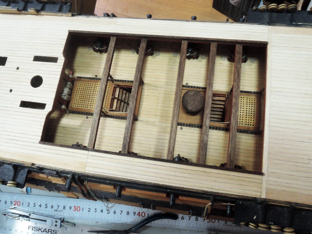
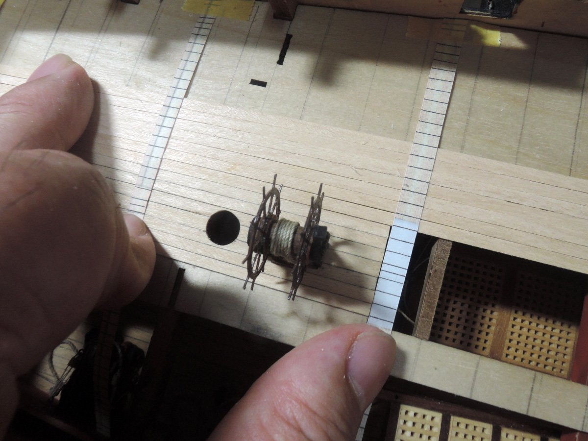
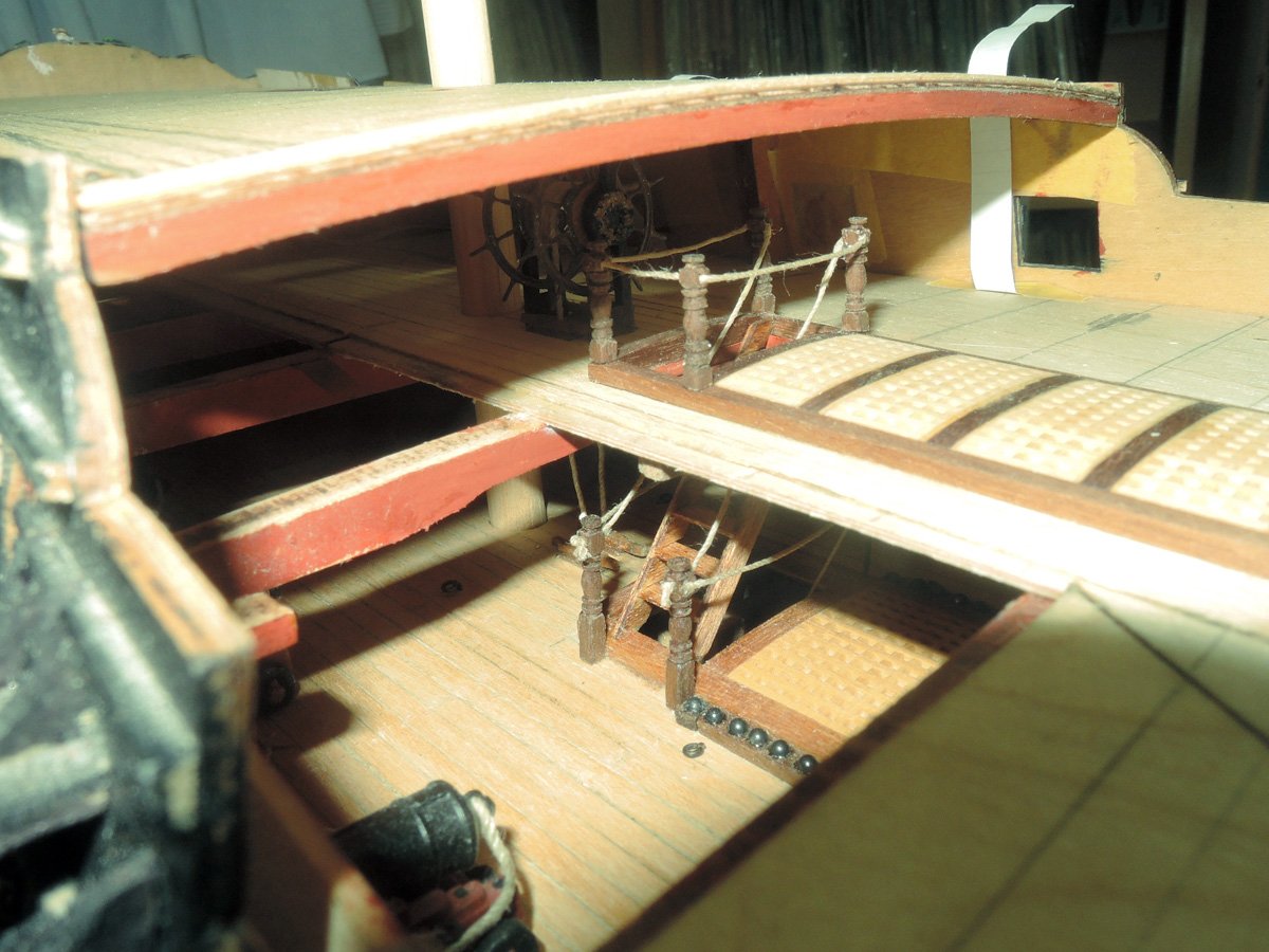
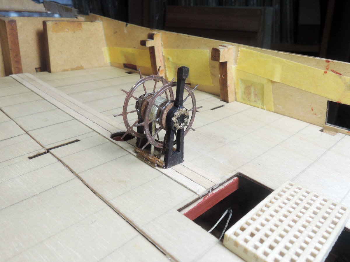
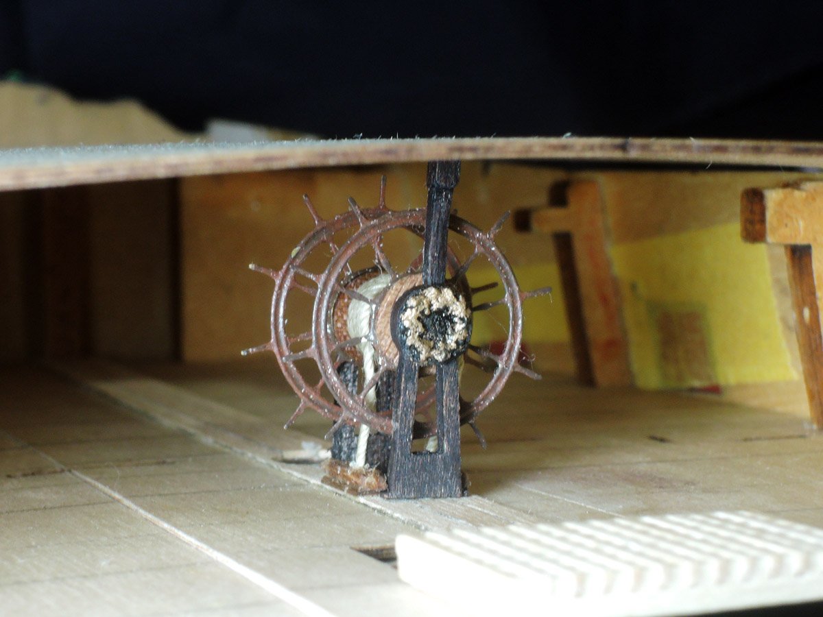
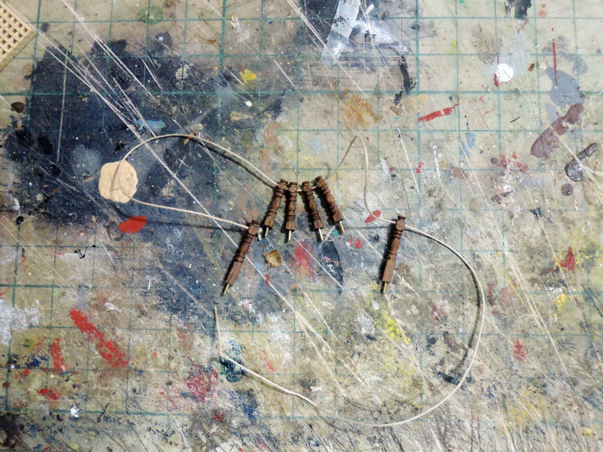
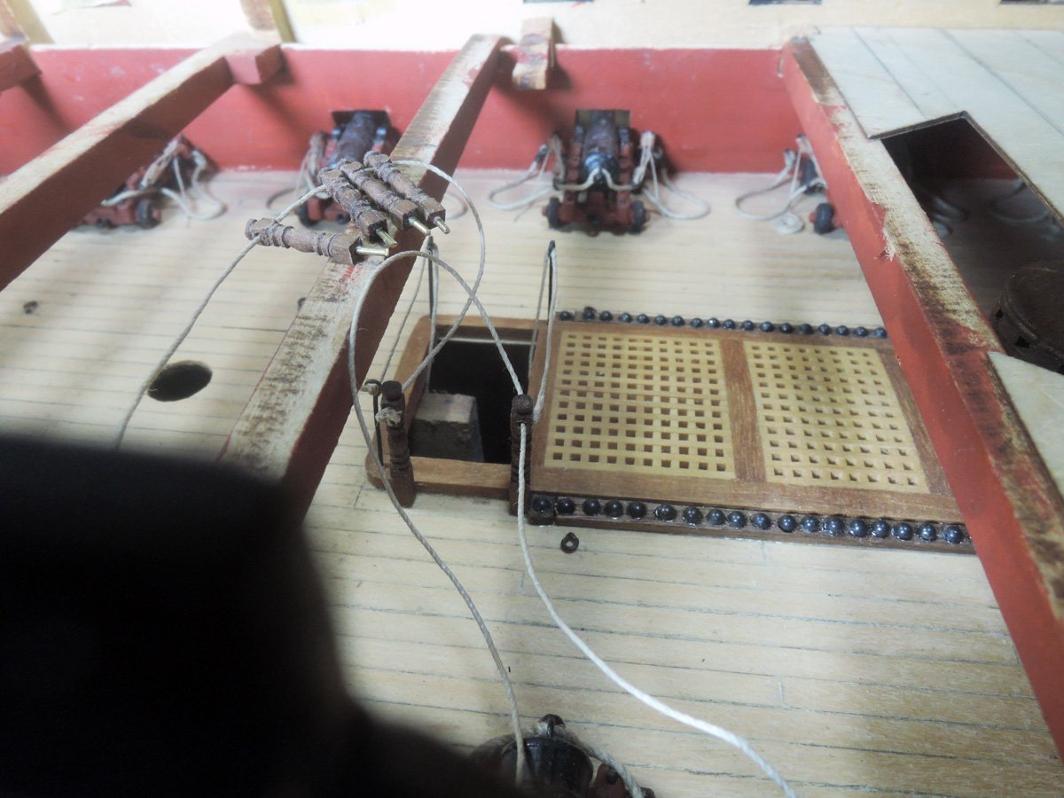
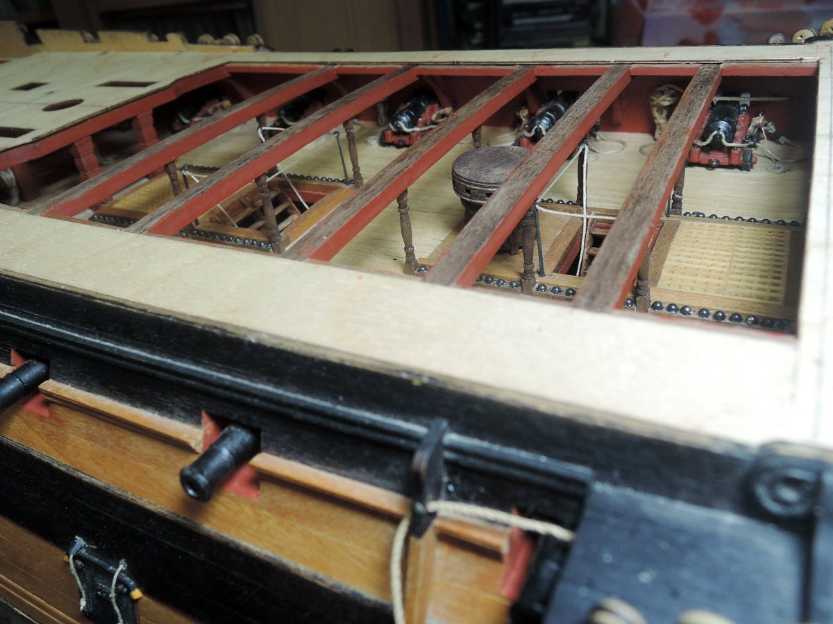
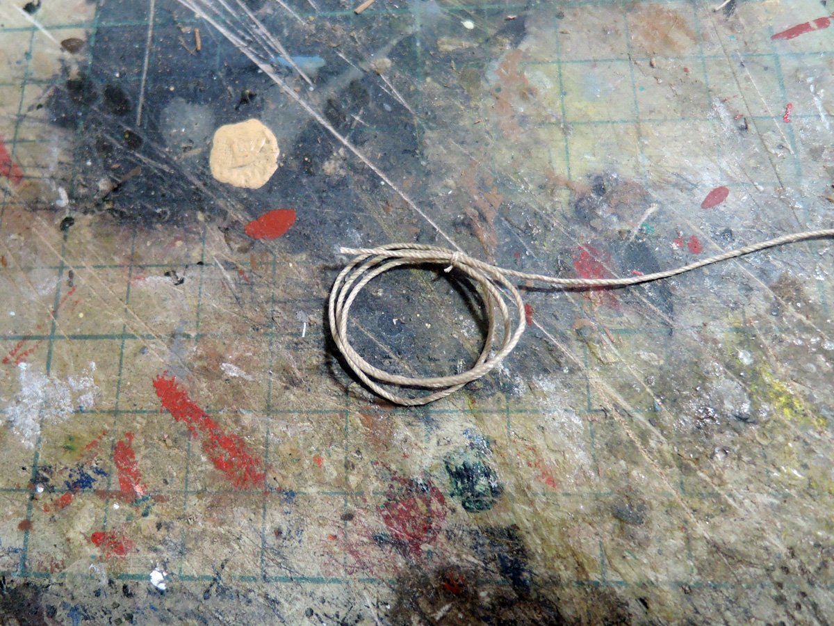
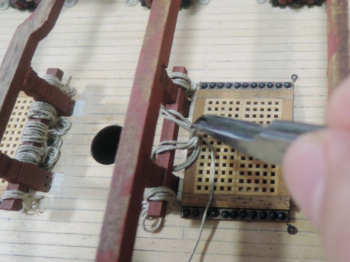
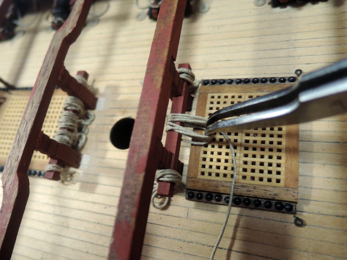
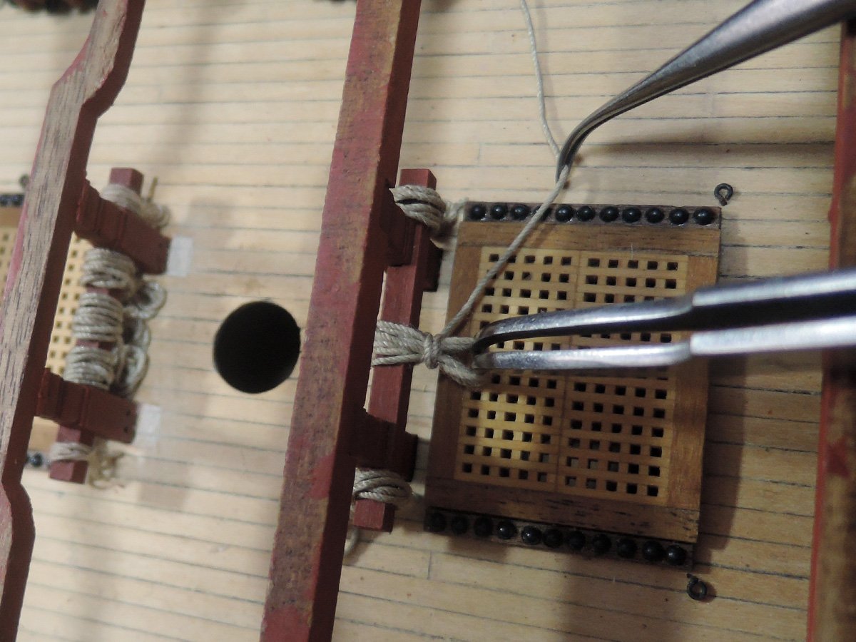
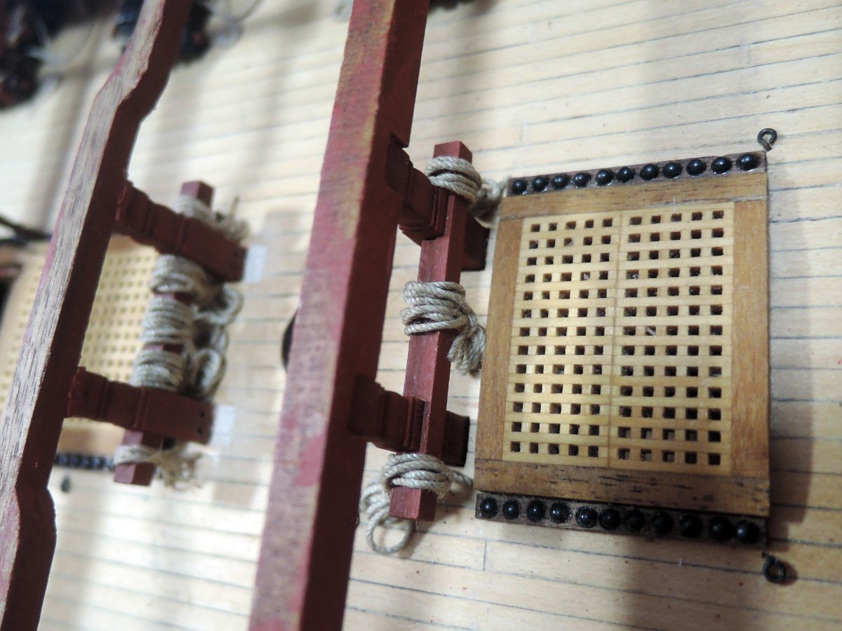
I firstly planked fore and aft centre area of quarterdeck because I had to finish tiller rope from wheel and rudder as well as its associating balusters and rail rope. These fittings are last parts to be fitted onto upper deck except heals of other rudders down from gangways or fo’c’sle deck which will be less troublesome.
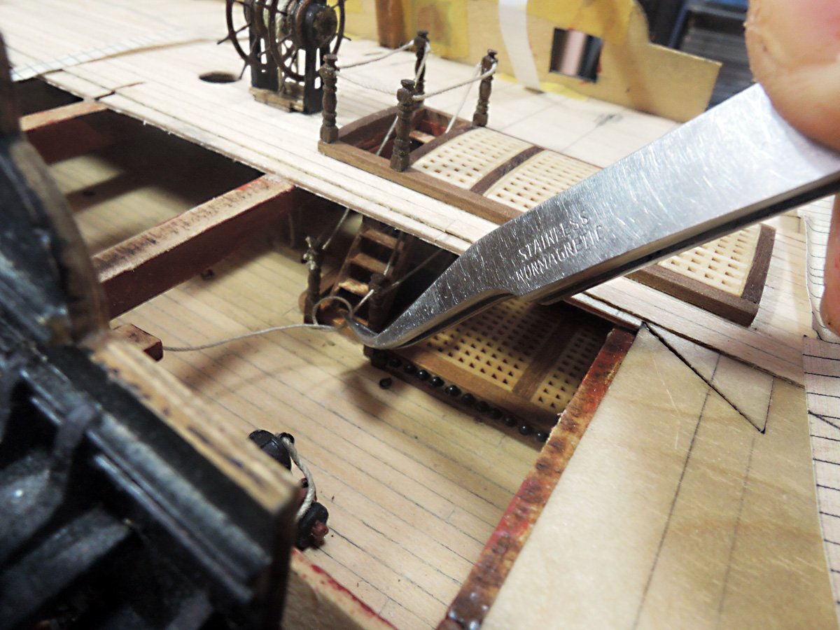
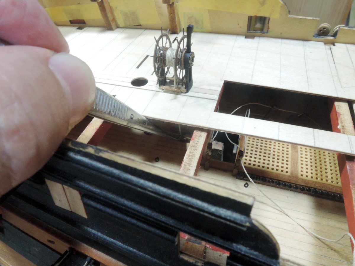
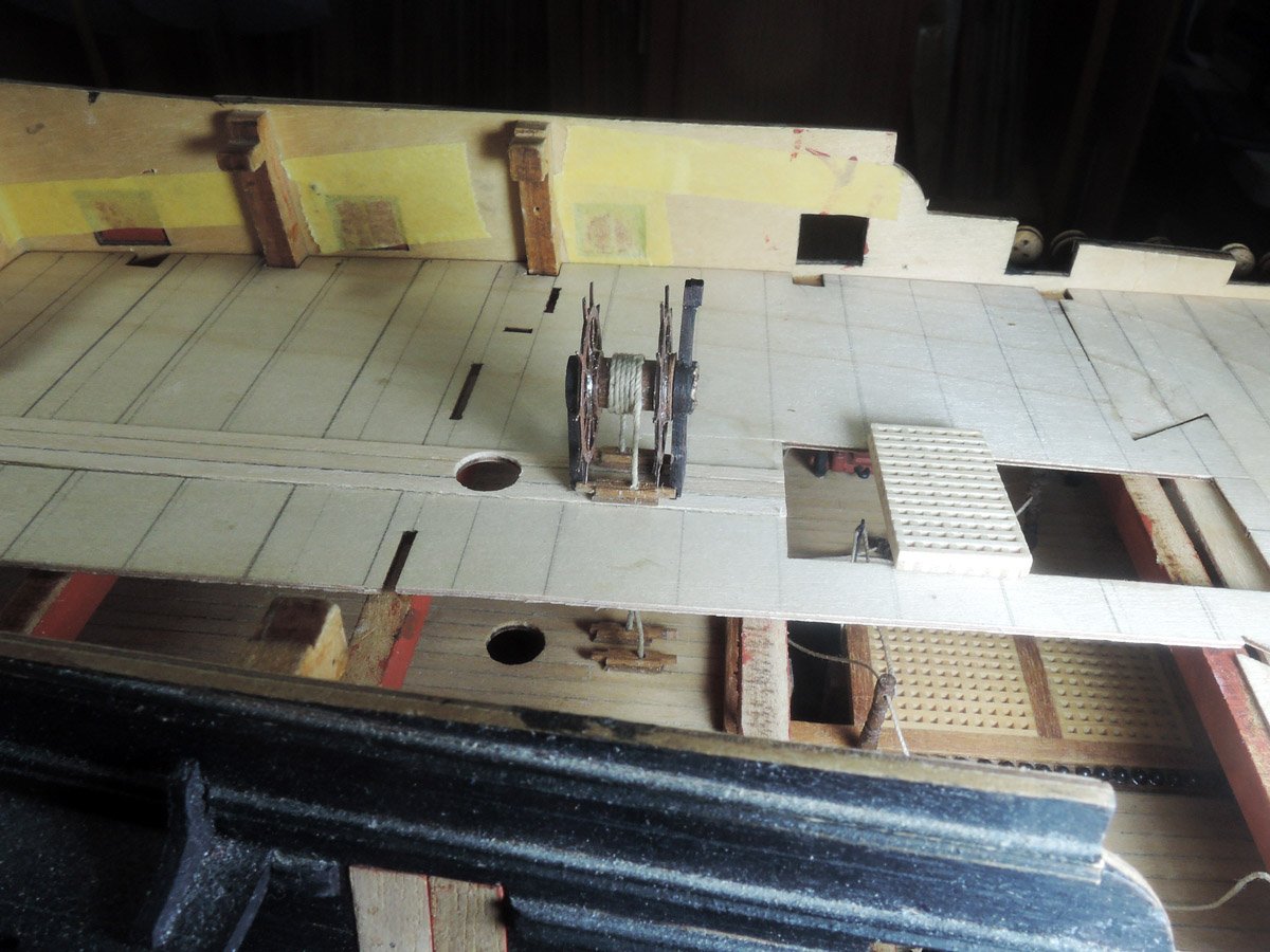
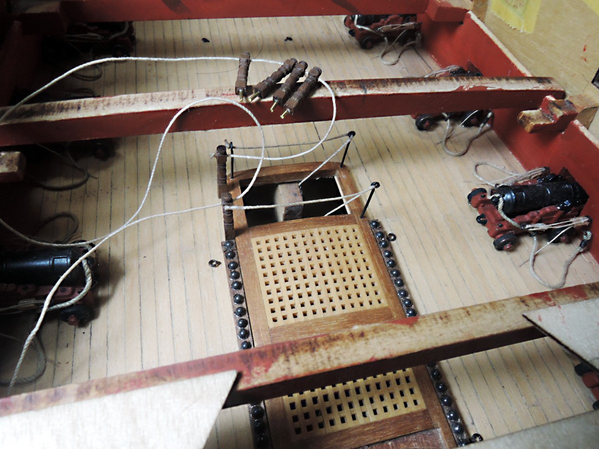
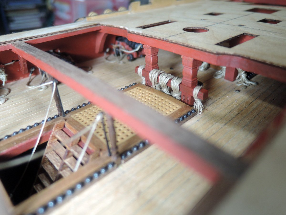
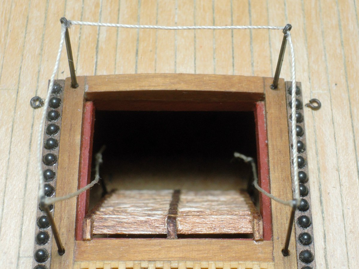
Tiller ropes and rudder rail rope are finally set using tweezers operated from starboard aperture of quarterdeck. Before gluing rest of quarterdeck baseboard, I photographed these areas with poop deck baseboard and stump mizzen mast dry fitted to their places. Although these areas will become can’t be seen as building proceeds, positional relationship of these fittings connecting several deck levels are quite understandable from this picture.
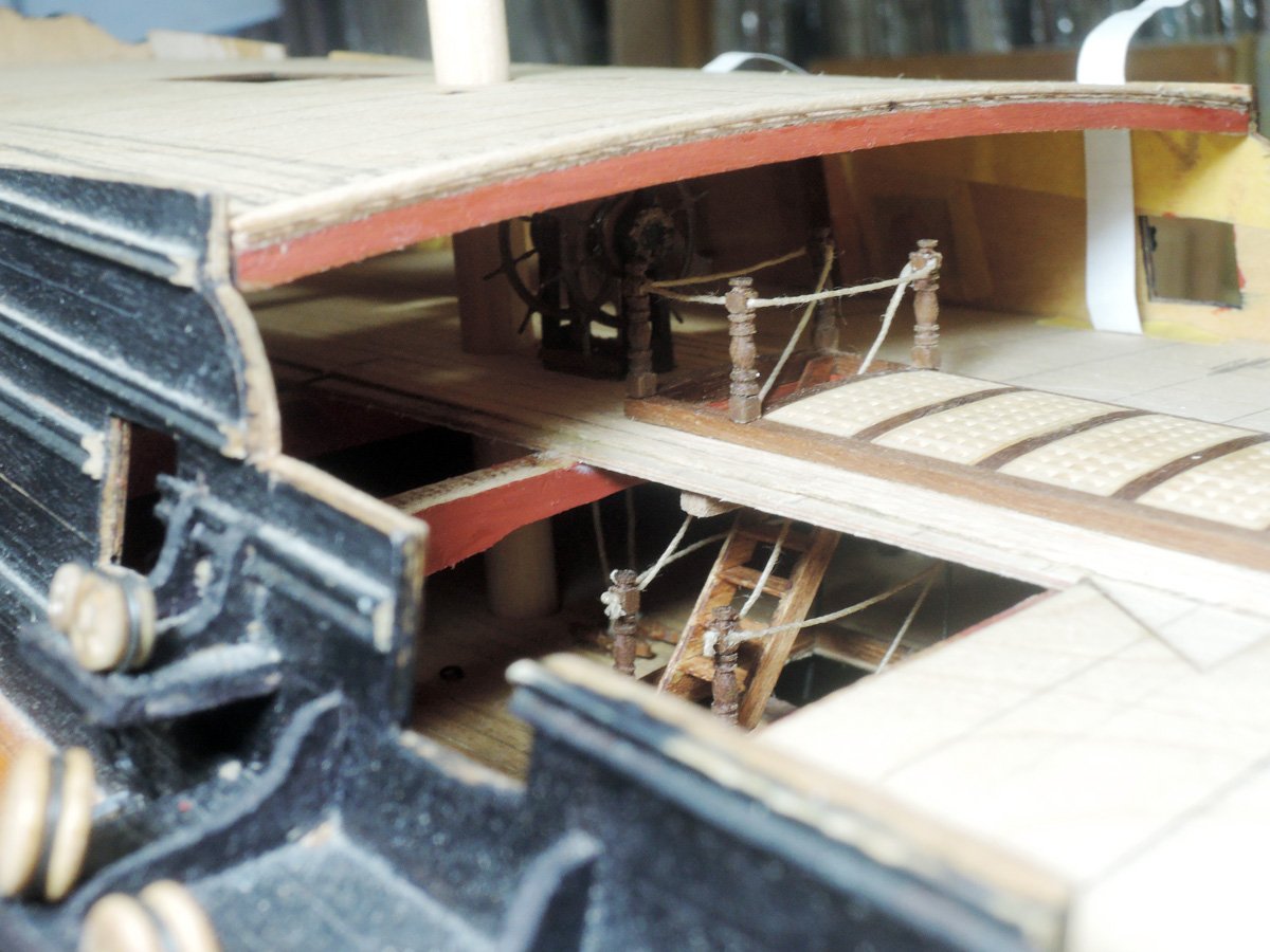
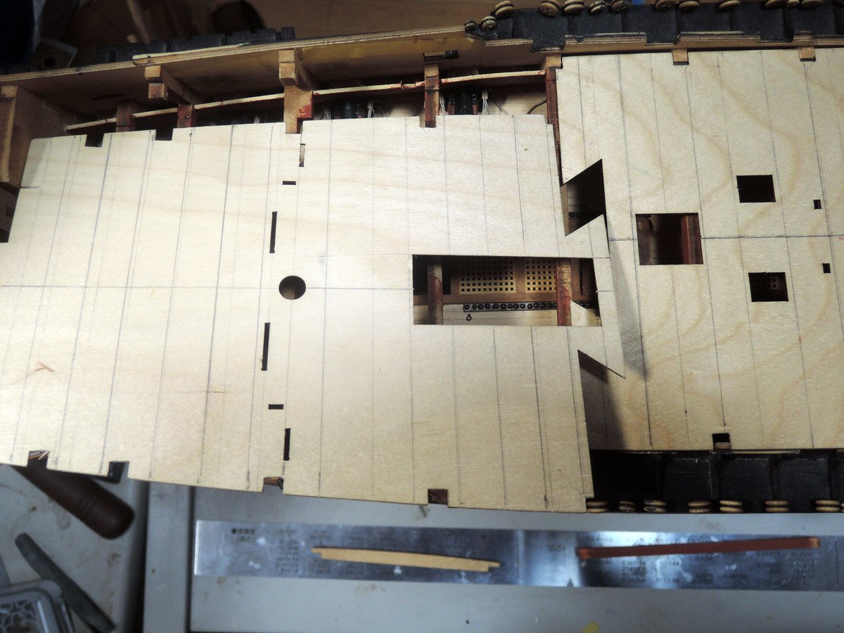
Rest of quarterdeck baseboard was finally glued.
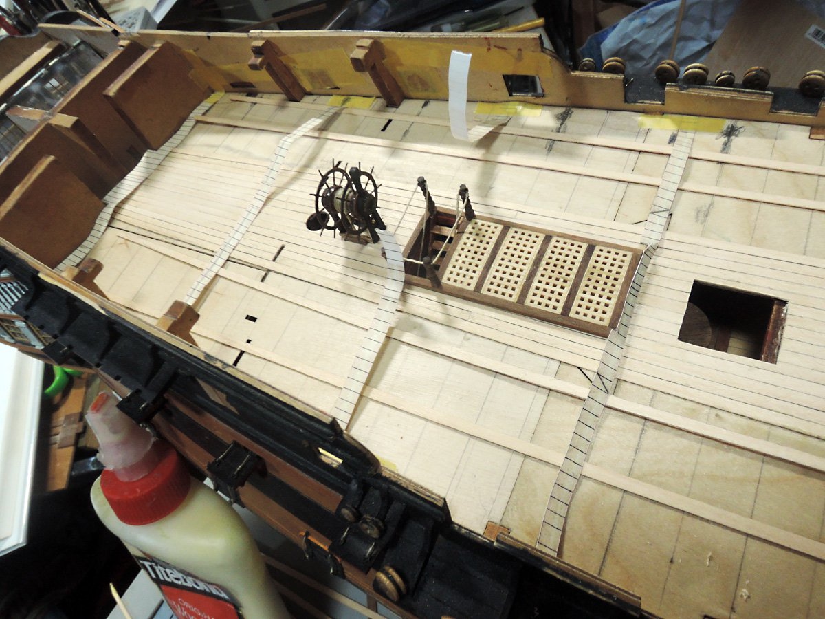
Although they can’t be seen clearly, tiller ropes are barely visible through rudderway opening by illuminating these areas carefully. I understand this is only my self-satisfaction, but at same time, I’m delightful to see representation of tiller ropes show their value.
- BenD, mort stoll, bruce d and 6 others
-
9
-
-
Bruce,
Thank you for your kind word.
Although some of items I had added may be hidden by other items, I myself am satisfied something is surely there behind other items.
It is value of building log to record these hidden details, and this is one of reason we modellers record building process.
-
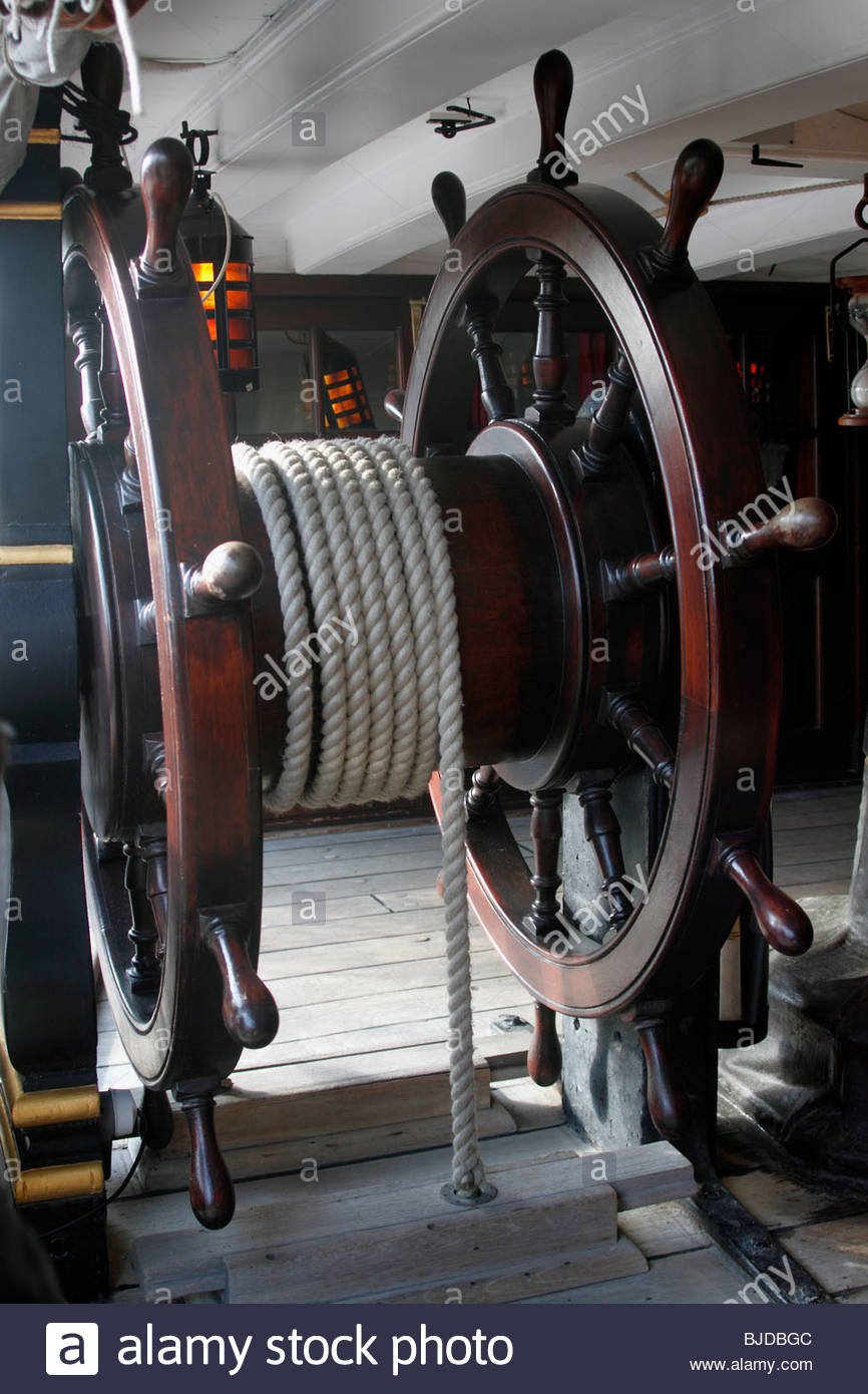
Steering gear
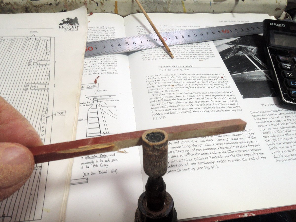
Though steering wheel is itself fitting of quarterdeck, I made it at this moment because I want to confirm tension of tiller rope down from quarterdeck to upper deck and point of upper deck sliding foots.
Sliding foots are clearly can be seen on Victory today.
https://andyandjudi.com/2017/07/10/hms-victory-portsmouth-historic-naval-dockyard/
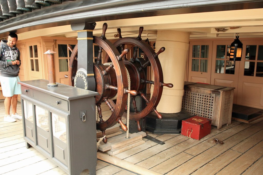
AOTS Victory shows sliding foots are also fitted onto upper deck. Except heels of ladders down from fo’c’sle deck, quarterdeck and gangways, they will be last parts to be fitted onto upper deck in my building.
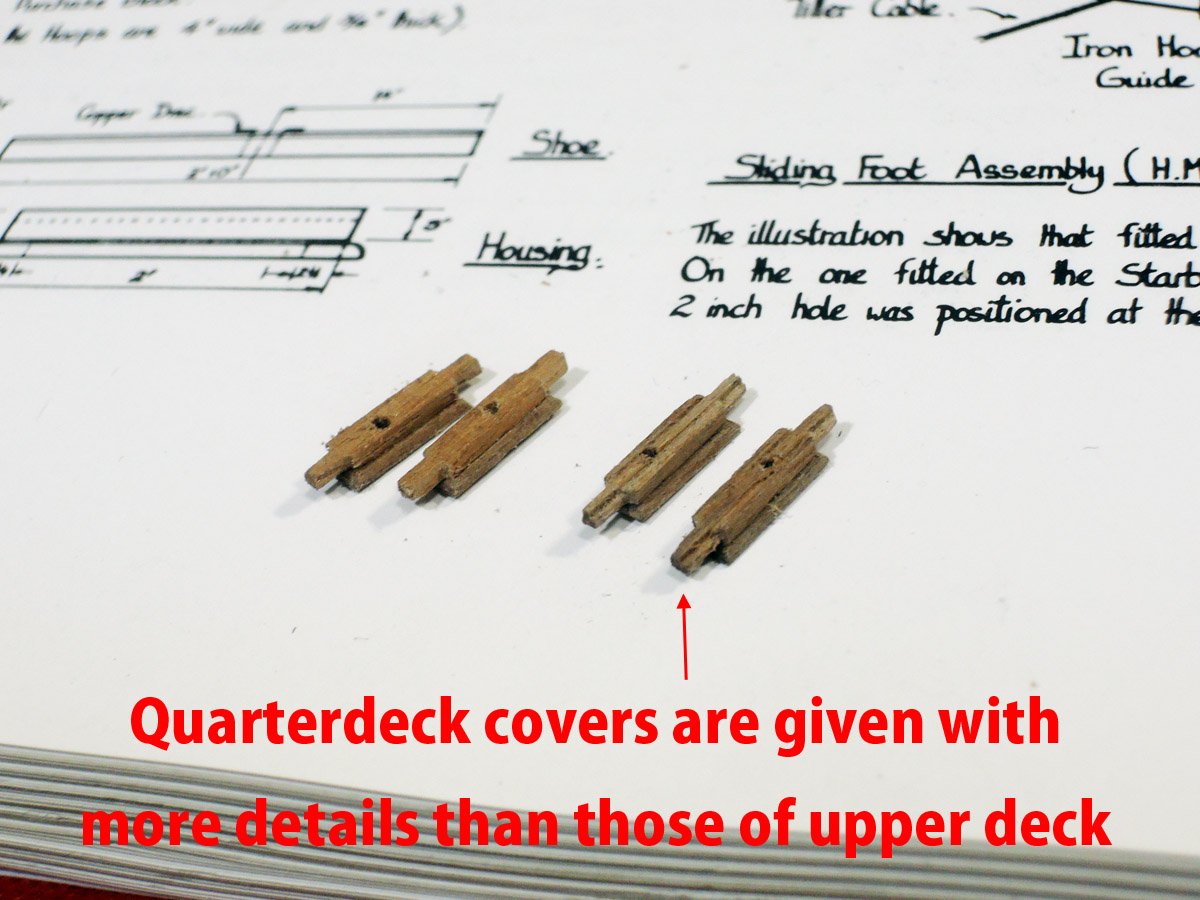
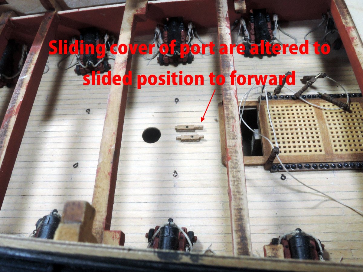
Base of sliding foot is 0.7 x 3 x 8.5 mm walnut and I rounded each edge. Sliding cover and rails of both sides are shaped as one part from 2 mm square walnut dowel and their lengths are 12 mm. These figures are referred to Goodwin’s “The Construction and Fitting”.
Those of upper deck are simplified shape, but for those of quarterdeck I add some details including rabbets of sliding cover to be hold into side rails、grooves between sliding cover and rails.
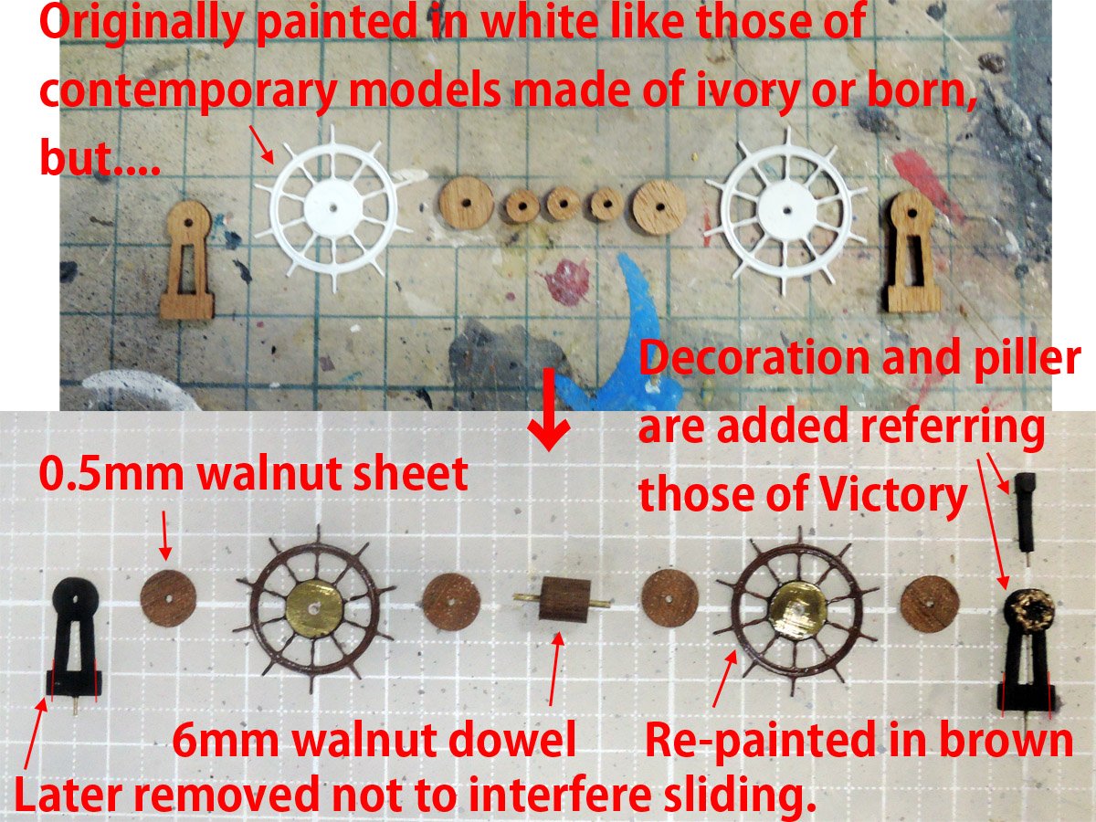
Wheels and their supports are upgraded. Decoration of forward support is made of 0.3 mm brass rod and Liquitex super heavy gel medium. Though it is apparently bigger than real one, I accept it considering my skill😅😅😅.
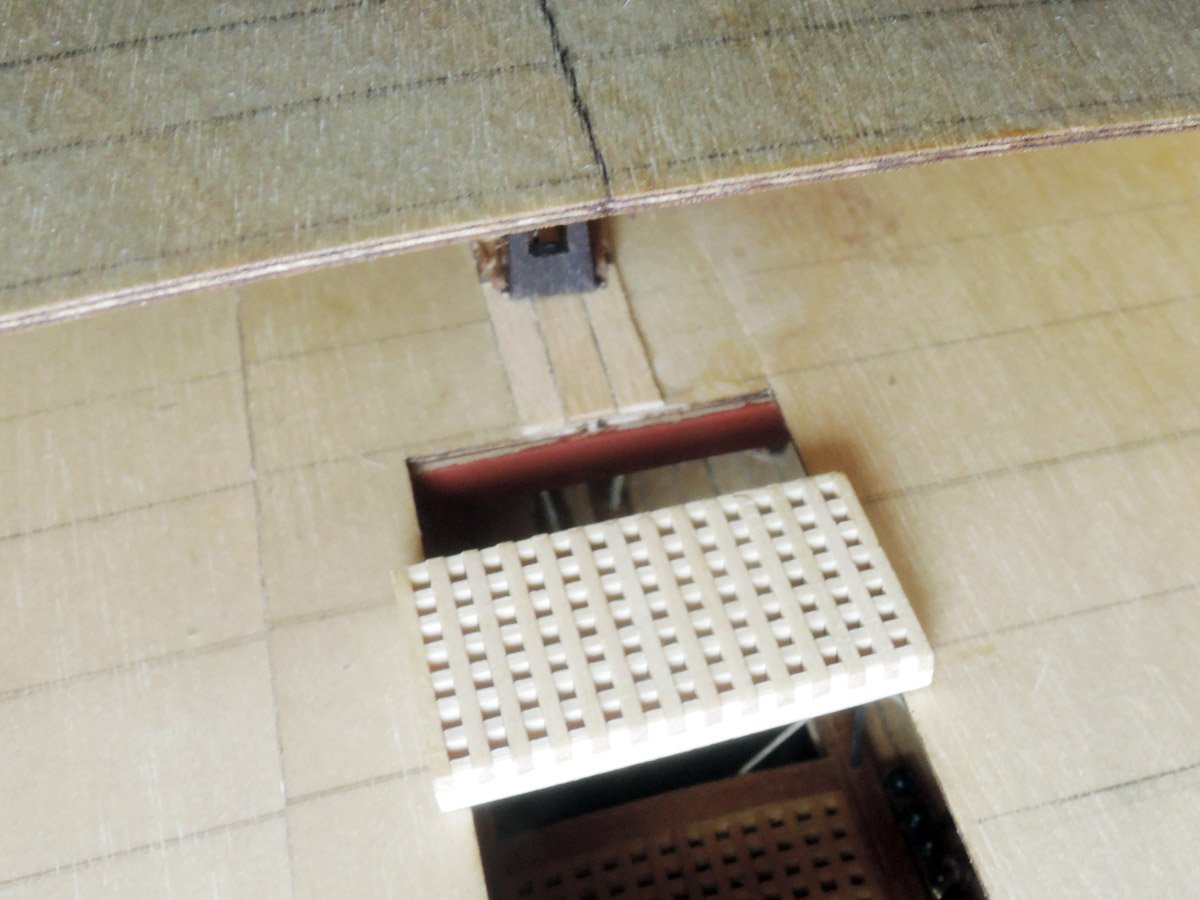
After constructions of these parts are finished, I dry fitted them into their places. I split quarterdeck baseboard into two parts at slightly starboard position of hatch opening. Tiller rope is spread with tweezers and passed through sliding foot on upper deck from starboard.
Depth of upper deck beam immediately aft of opening is thick because of rigidity, but I thinned it to show tiller rope more clearly.
After finishing dry fitting including rest of quarterdeck baseboard, poop deck baseboard and grating just before of ladderway opening,-I shed light there. Happily tiller rope and sliding foot are can be seen through opening. They may be able to seen well after fitting of ladder of this area.
Next, I want to start construction of fo’c’sle deck, quarterdeck and gangways.
- mort stoll, mtaylor, CiscoH and 3 others
-
6
-
James,
Thank you for your comment.
Sometimes, it is very difficult to guess details of specific ship of specific date, so we have to seek infos of other ships of same era.
While I'm still unconfident of authenticity of my skid beams construction, I satisfy that they themselves seem to be rigid with pillars and hanging knees😅
- mtaylor, James H and chris watton
-
3
-
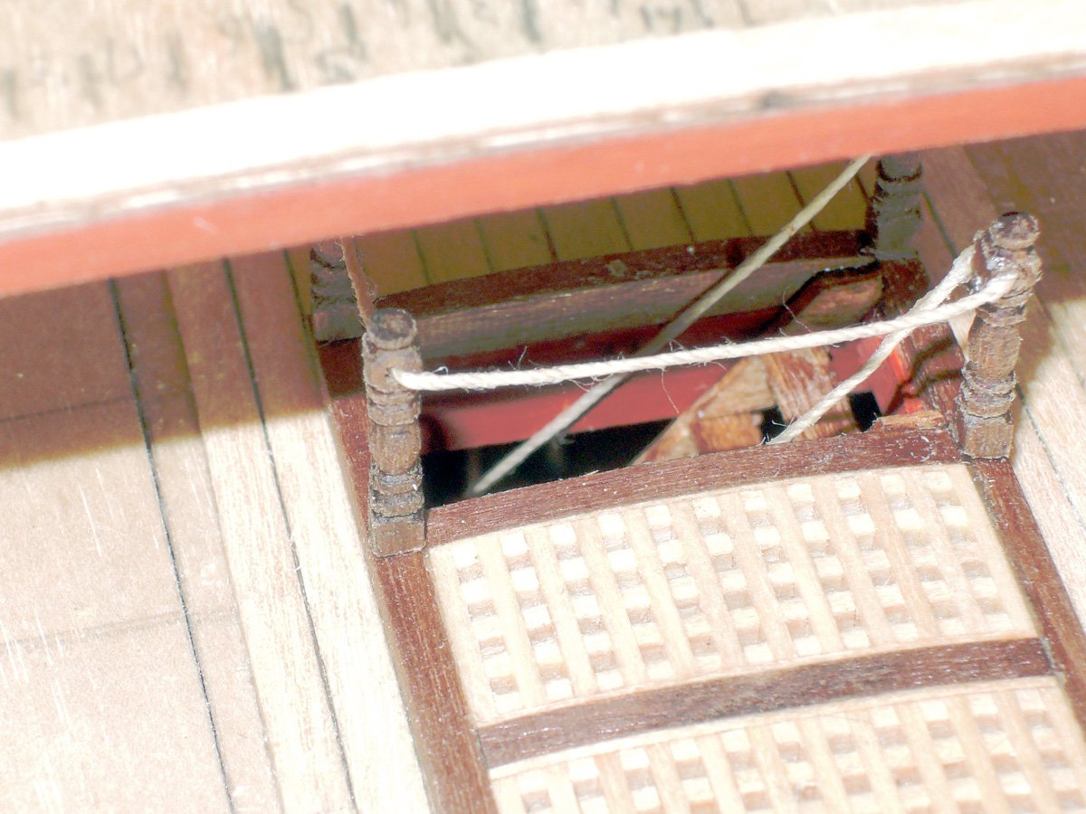
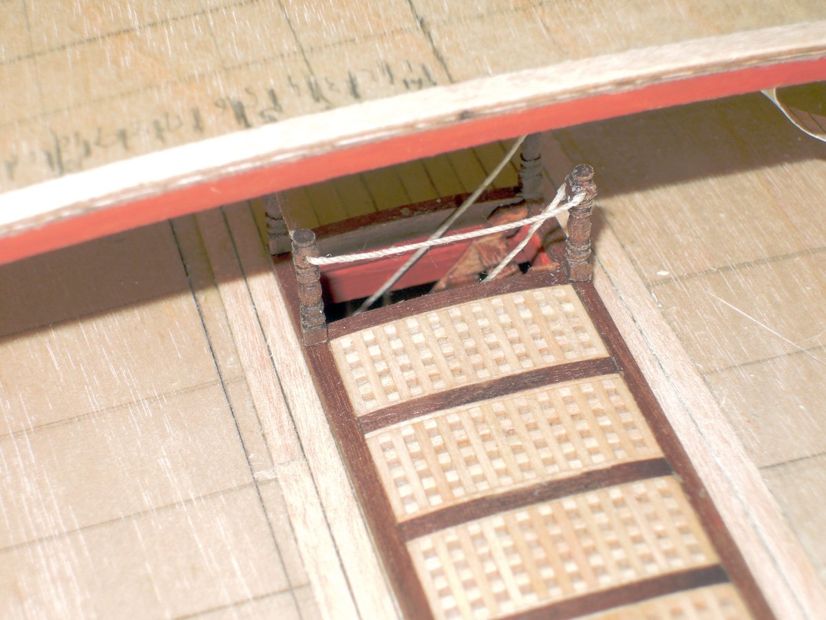
Balusters for ladder railings between quarterdeck and upperdeck
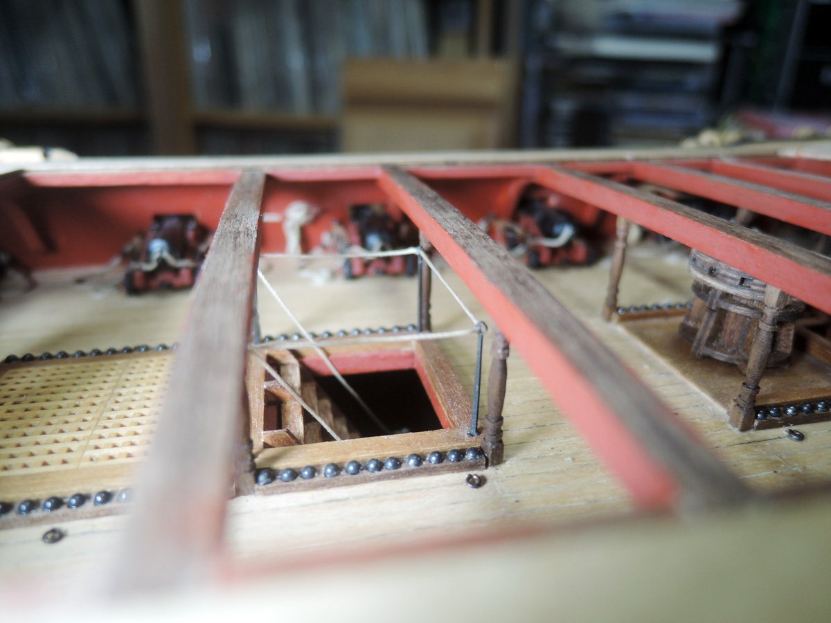
Maybe they will be scarcely seen from openings once model competes, I added two balusters beside of aftermost coaming of upperdeck. They will form set of balusters for ladder handrails between quarterdeck and upperdeck. They were shaped of 2 mm walnut dowel referring AOTS Victory. Along with upperdeck balusters, I also shaped those for quarterdeck. Required numbers for them are only 6, so I shaped them without help of jig.
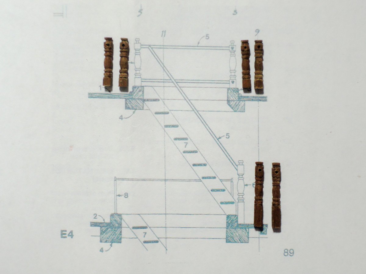
I passed handrail rope through holes of every 6 balusters at this moment.
Handrail rope is prepared with excessive length. I’m planning to split quarterdeck baseboard at slightly starboard of hatch opening. I will place split baseboard, plank, make hatch coaming, place quarterdeck balusters, then pull one end of rail rope, knot there and cut excessive rope. Rest of baseboard of port side will be glued and planked after these works finished.
Along with balusters, position of quarterdeck beam of this area is also altered. As a nature of POB ship model, deck beams are lined with bulkheads. But deck beam of this area is running across ladderway opening in kit design. So I made slots to inner planks slightly rear of this bulkhead and notched surplus deck beam there.

Forwardmost beam of fo’c’sle deck of kit is also running across ladderway opening position showed on Elephant plan. Ladderway opening of kit design is situated rearward of that of Elephant plan to prevent deck beam lined with bulkhead. Beam of this area is also notched to new slots as did at quarterdeck. Opening of deck baseboard is also altered.
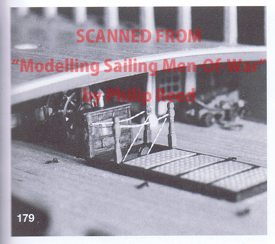
BTW ladder rails between these decks of Victory today seem to be wooden or iron bars. But I used rope according to 1/128 Majestic model built by Mr. Philip Reed.
https://www.shipmodel.com/acadp_listings/majestic/
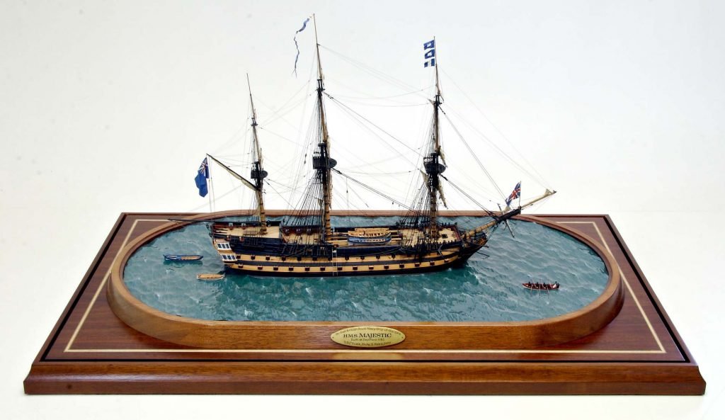
Images of above link don't include its detail, but in his book "Modelling Sailing Men-Of-War", Mr. Reed used rope rail for this place. Maybe it would be right for 74 gun ships which were mass-produced in enormous numbers.
Alongside with these balusters and rope, stanchions and handrail ropes of ladder to lower deck are partially represented. Stanchions are made from 0.5 mm brass rod, because kit PE sheet doesn’t include surplus stanchions.
Next, I will make sliding covers for tiller rope behind this area. They will be last parts to be fitted onto upper deck.
- Barbossa, GrandpaPhil, ccoyle and 4 others
-
7
-
Skid beams
Boat stowage method of wooden warships is one of major items which significantly changed through 18th century.
Model of 50 gun ship around 1714 shows boat stowed on spare spars hang on between fo'c'sle break and main bits.
https://collections.rmg.co.uk/collections/objects/66357.html
Model of Victory in her original form around 1765 shows gangways are connecting between fo'c'sle and quarterdeck at slightly lower level than fo'c'sle and quarterdeck. Boat is stowed on skid beams on iron crutches projecting from inboard edge of gangways.
https://collections.rmg.co.uk/collections/objects/66473.html
Although skid beams and boat are omitted, model of Queen Charlotte of 1789 shows almost same boat stowage method with Victory model, except gangways are raised to same height with fo'c'sle and quarterdeck.
https://collections.rmg.co.uk/collections/objects/66516.html
Sectional model of 74 gun ship around 1795 shows significant change. Skid beams became permanent structural members of the ship and are placed below the gangways. Gangways themselves seem to be broader than ever.
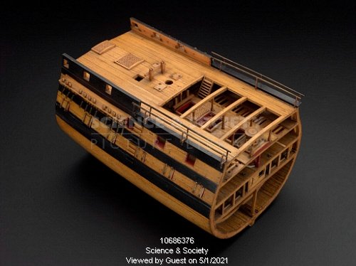

Victory today in Portsmouth also has skid beams below the gangways, but details of them show not a few differences from 74 gun ship sectional models.
https://www.alamy.com/hms-victory-gun-deck-portsmouth-image212002530.html
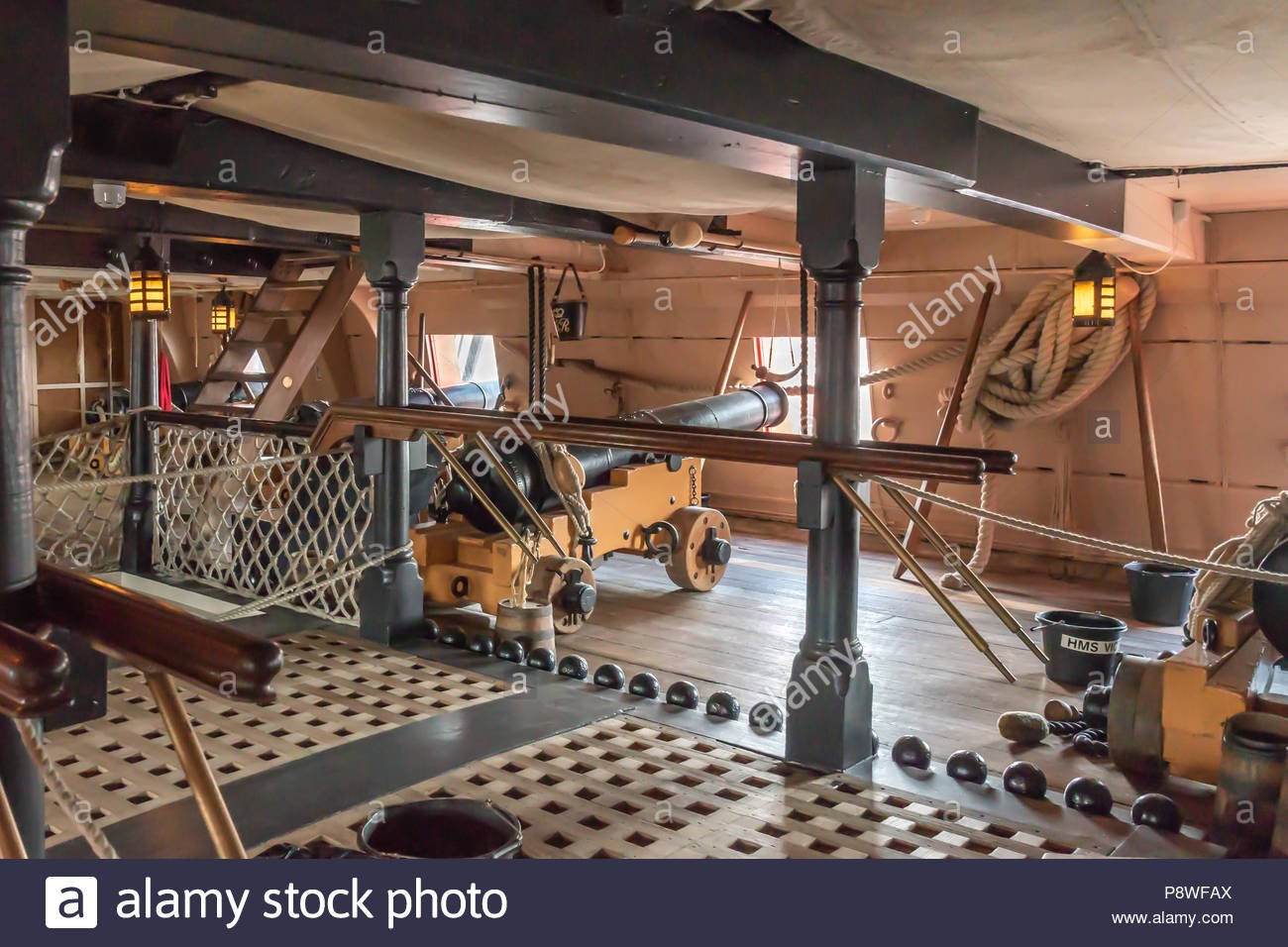
While skid beams of sectional model have hanging knees, those of Victory today have no hanging knees. Instead many Victory reference books are showing skid beams are notched to slots of inner planks. Skid beam of former seem to be directly above of beams of upperdeck judging from skid beam pillars situating near the corner of coamings. OTOH many Victory reference books are showing there are no connection between upper deck beams and skid beams. Finally, pillars of sectional models are fitted to immediately outboard of coamings and those of Victory are fitted on coaming themselves.
I can't judge which method is most appropriate for Bellerophon. Considering her building time, her boat stowage method would be same as Queen Charlotte model. But there is also strong possibility that skid beams were altered to permanent structure during her long career. After some (or much?) thought, I finally decided to follow the method of 74 gun ship sectional model.
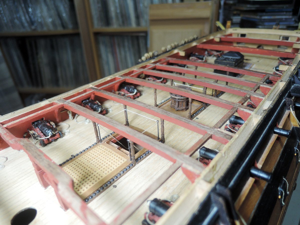
Skid beams themselves are laser cut parts of kit. Pillars are shaped from 2 mm walnut dowel. Total numbers of 12 pillars are required, 2 for each 5 skid beam, 2 for aftermost fo’c’sle deck beam. So I made simple jig from plastic.
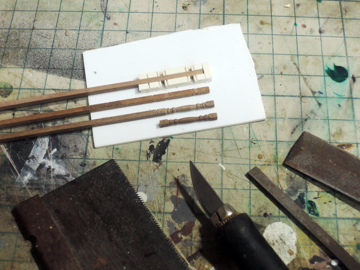

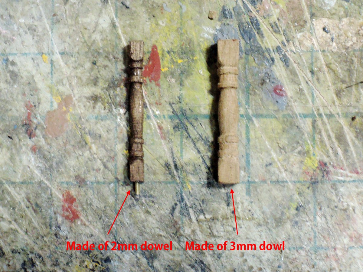
I firstly tried making pillar from 3 mm dowel, but it seems to be slightly fat. Pillars shaped from 2 mm dowel seem to be slimmer than those of 74 gun ship sectional model. But those of Victory today also seem to be slim, so I decided to go on 2 mm dowel.
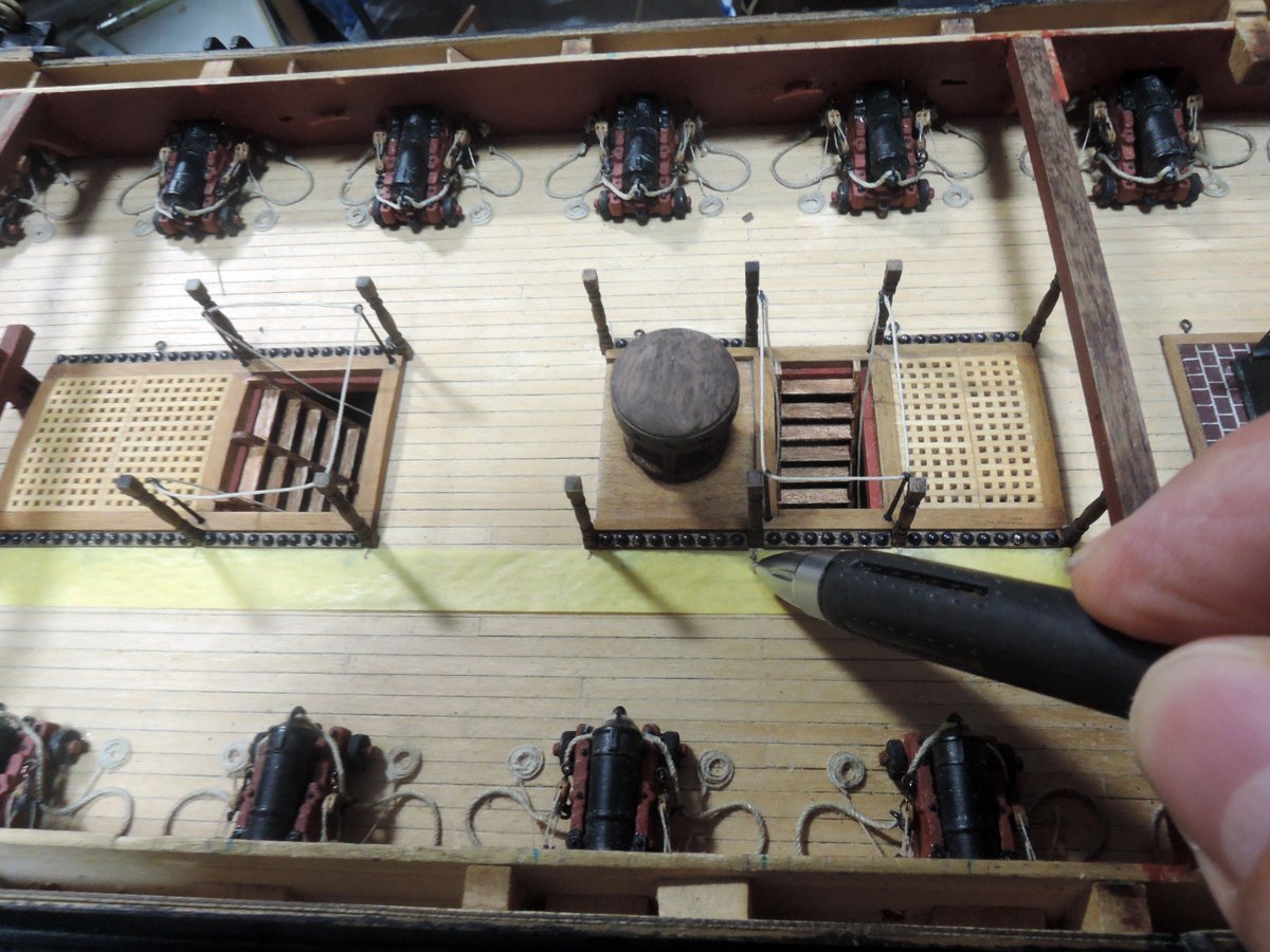
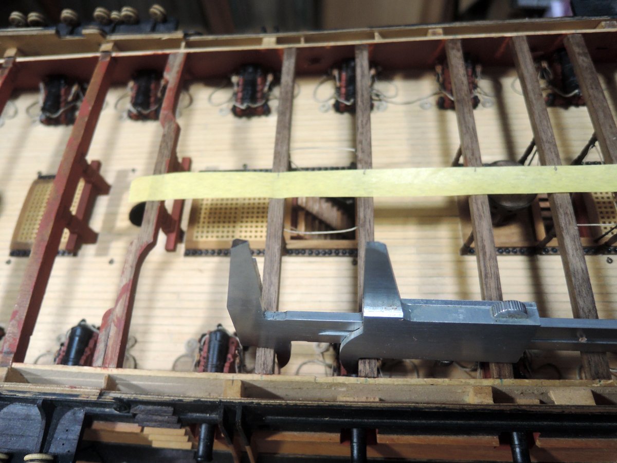
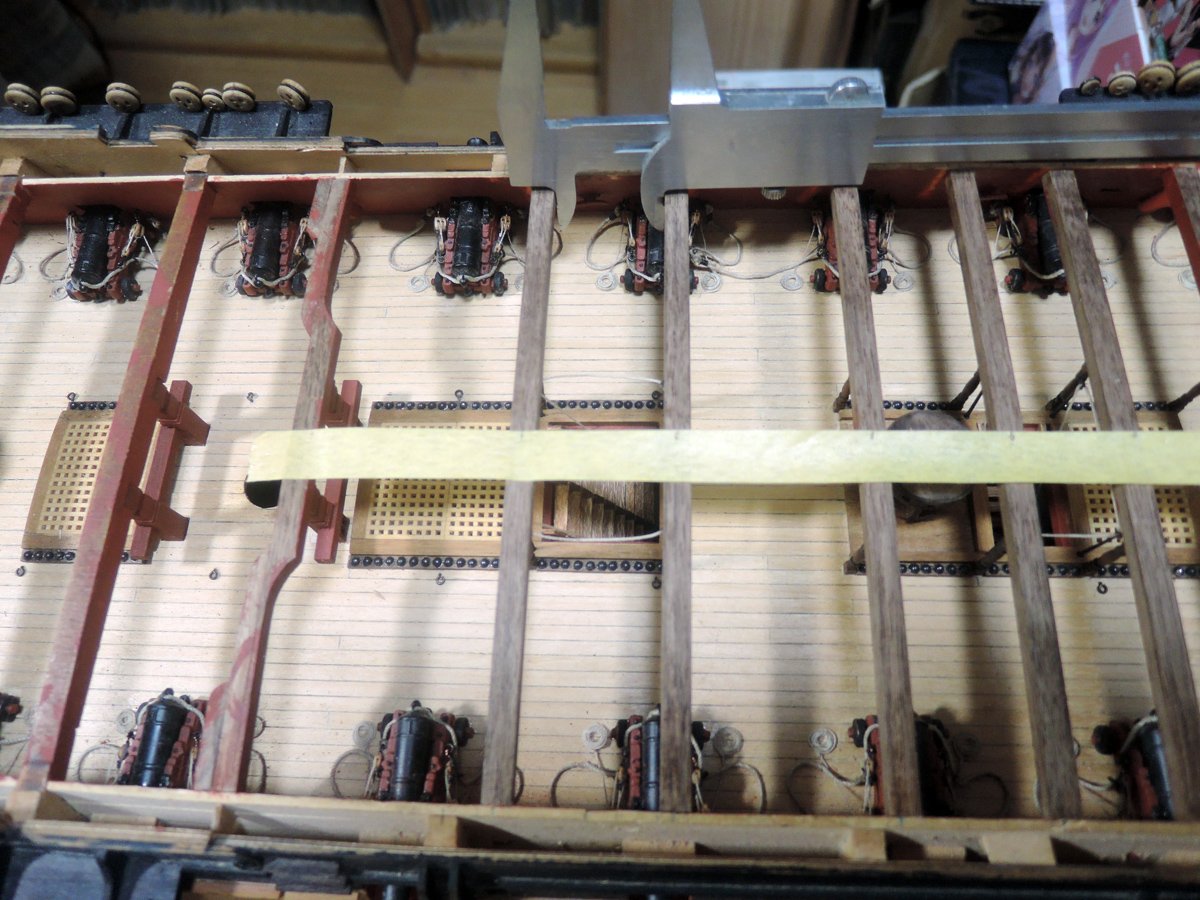
To placing skid beams directly above of pillars, I stack masking tape on upper deck, marked position of pillars, peel off it, stack it between rearmost fo'c'sle beam and foremost quarterdeck beam, then decided positions of skid beams with help of calliper to maintain equal intervals for both end of starboard and port.
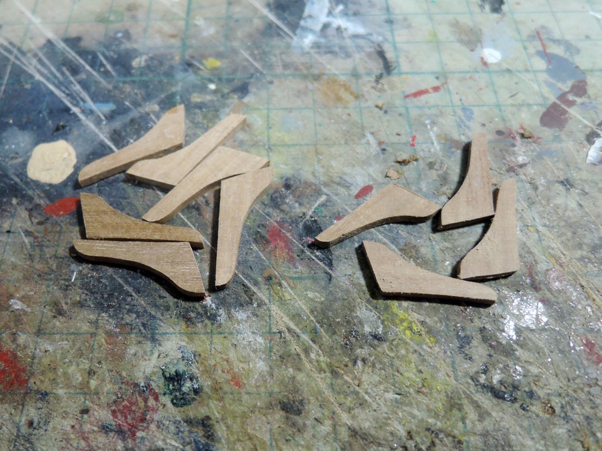
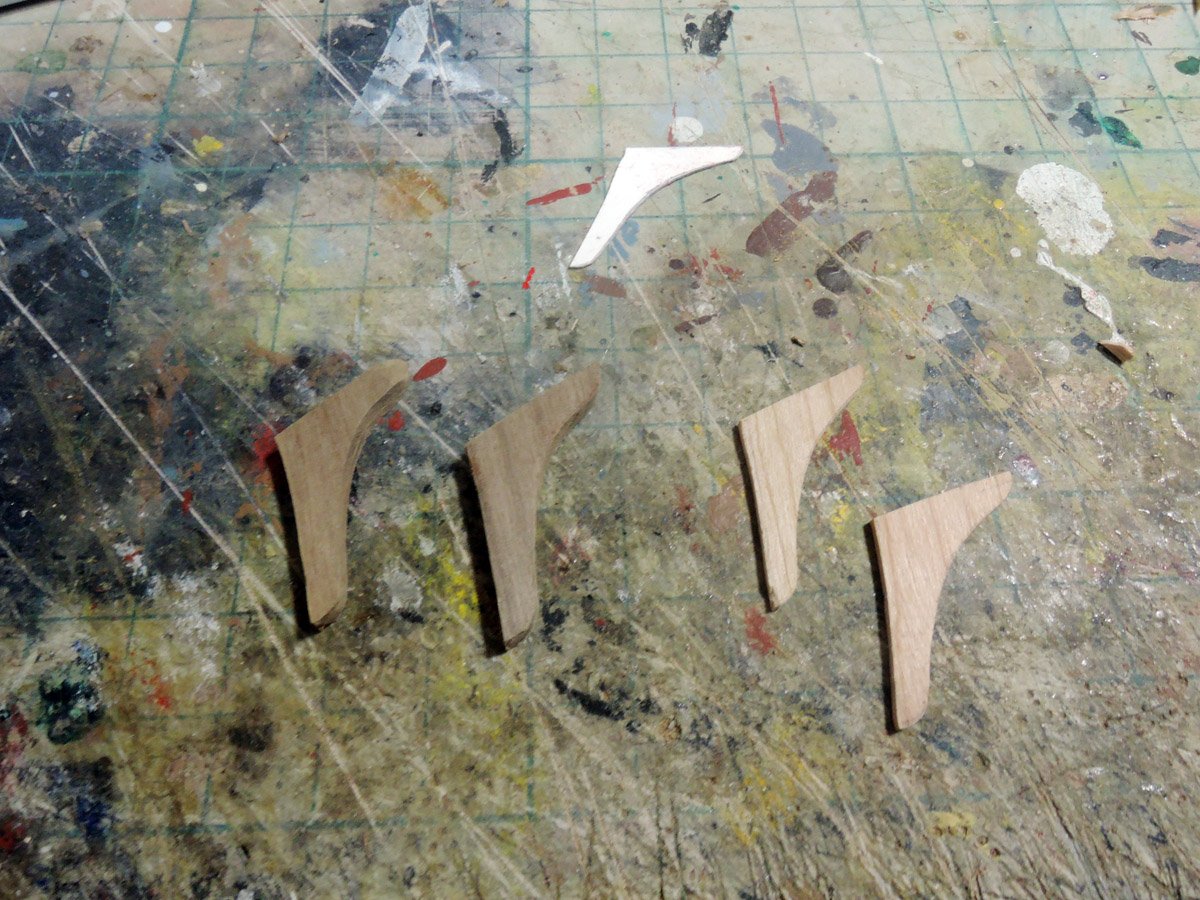
Hanging knees are shaped from 2 mm walnut sheet.
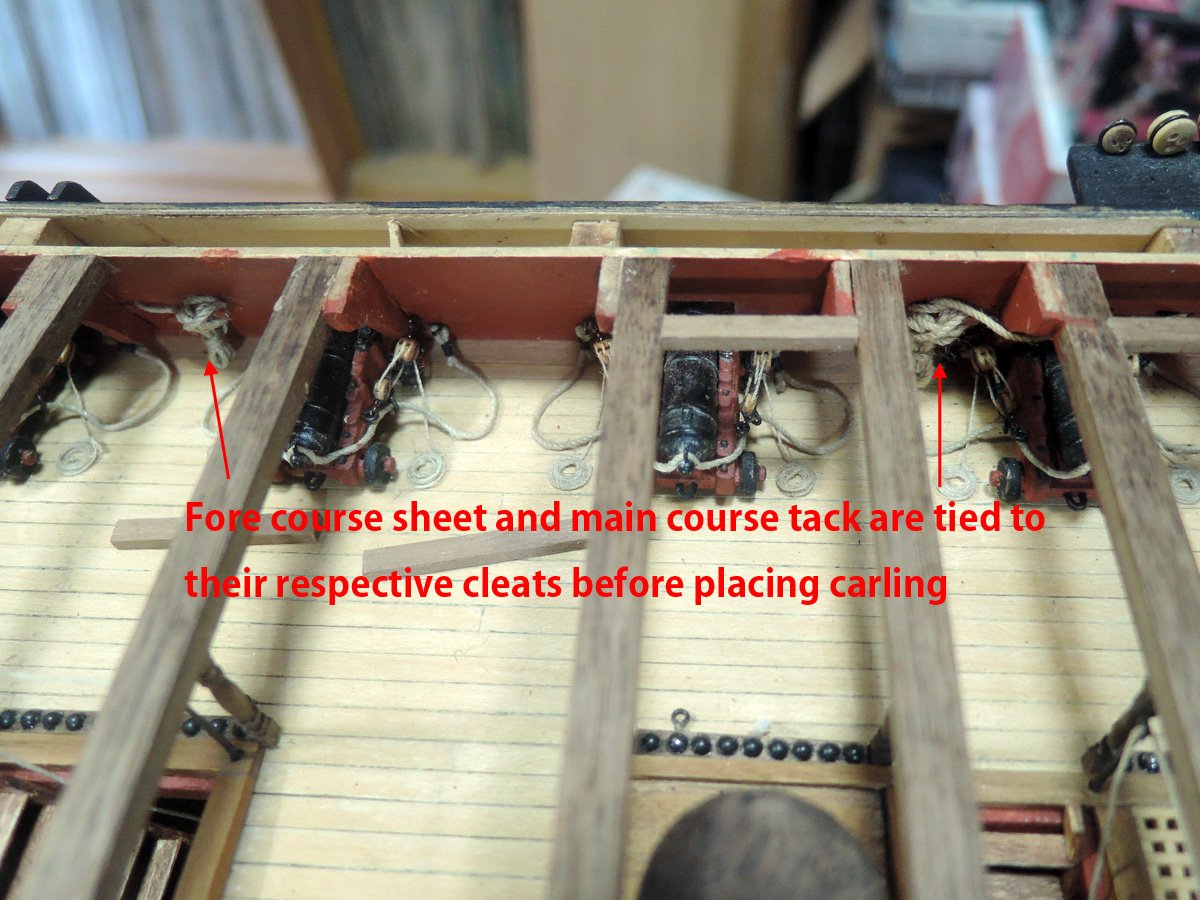
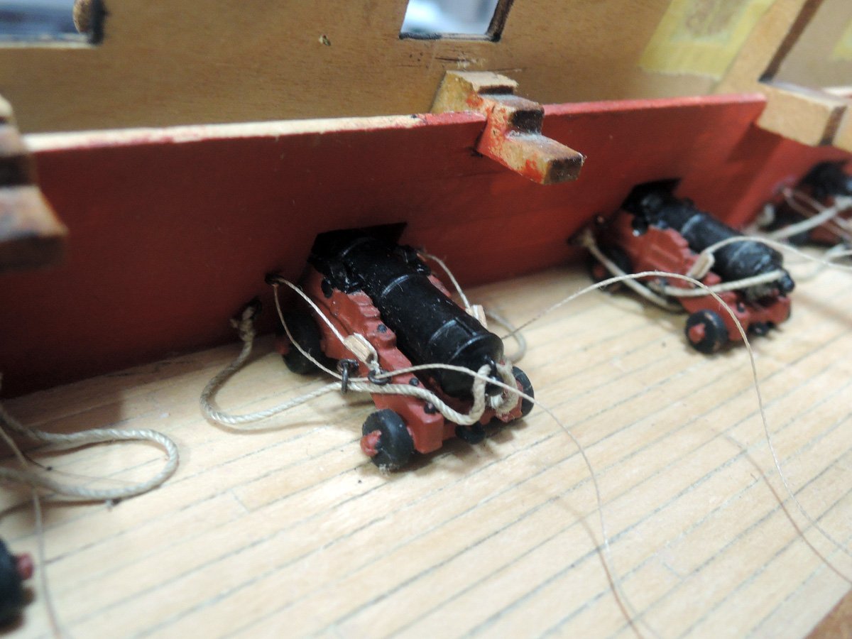
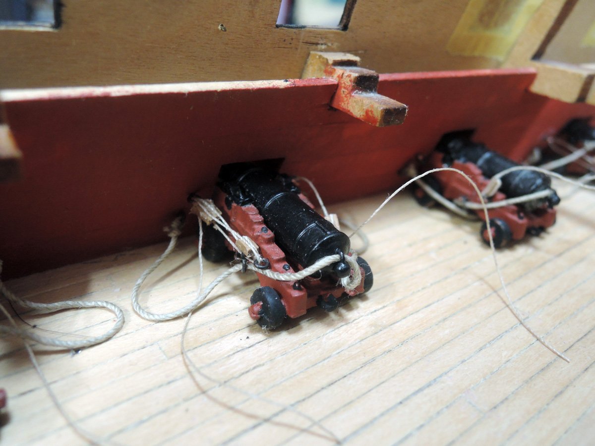
Main course tacks and fore course sheets are tied to each cleat at this stage. Gasket coil like ones are separately made and CA glued there. Another end of each rope is passed through each sheave and hung on outboard, gasket coiled there until rigging stage.
Carlings are also added with 2 x 3 mm walnut. They are glued to just inboard of kit gangway baseboard so that I can broaden width of gangways later.
Hanging knees are also added to aftermost fo'c'sle deck beam and foremost quarterdeck beam. AOTS Bellona shows knee of former is thin and latter is thick. So I used 1.5 mm sheet for former and 3mm walnut for latter.
BTW, to my eyes afterend or break of fo'c'sle of kit design seems to be slightly rearward than it should be. I cut that area of fo'c'sle deck baseboard (approximately 1.5 mm width), aftermost fo’c'sle deck beam are glued to fit this position.
Although kit rigging plans show only ends of foretop yard braces are tied to main bit. But I added other rope coils to crossbars of main bits.
- GrandpaPhil, bruce d, James H and 6 others
-
9
-
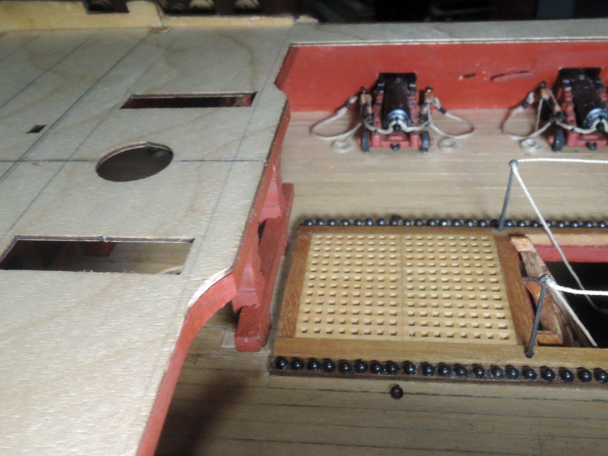
Correction of forwardmost quarterdeck beam
NMM Elephant plan shows forwardmost quarterdeck beam is curved and protruding forward at its centre like the other Slade designed 74.
https://commons.wikimedia.org/wiki/File:Elephant_(1786)_RMG_J2938.png
Also position of forward main bit of kit design are slightly rearward than it should be comparing Elephant plan. It may be more natural to move bits slightly forward so that they support centre portion of foremost quarterdeck beam protruding forward.
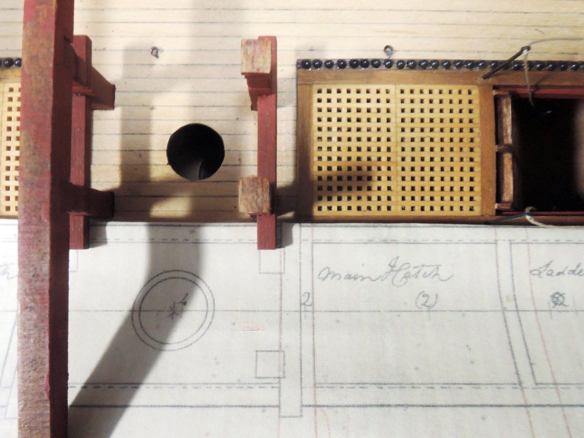
Bits are already glued tightly as per kit design. So I have to cut them from deck carefully. They are re-glued slightly forward by help of brass rod as reinforcement. I also engraved dummy sheaves to bits utilising this opportunity.
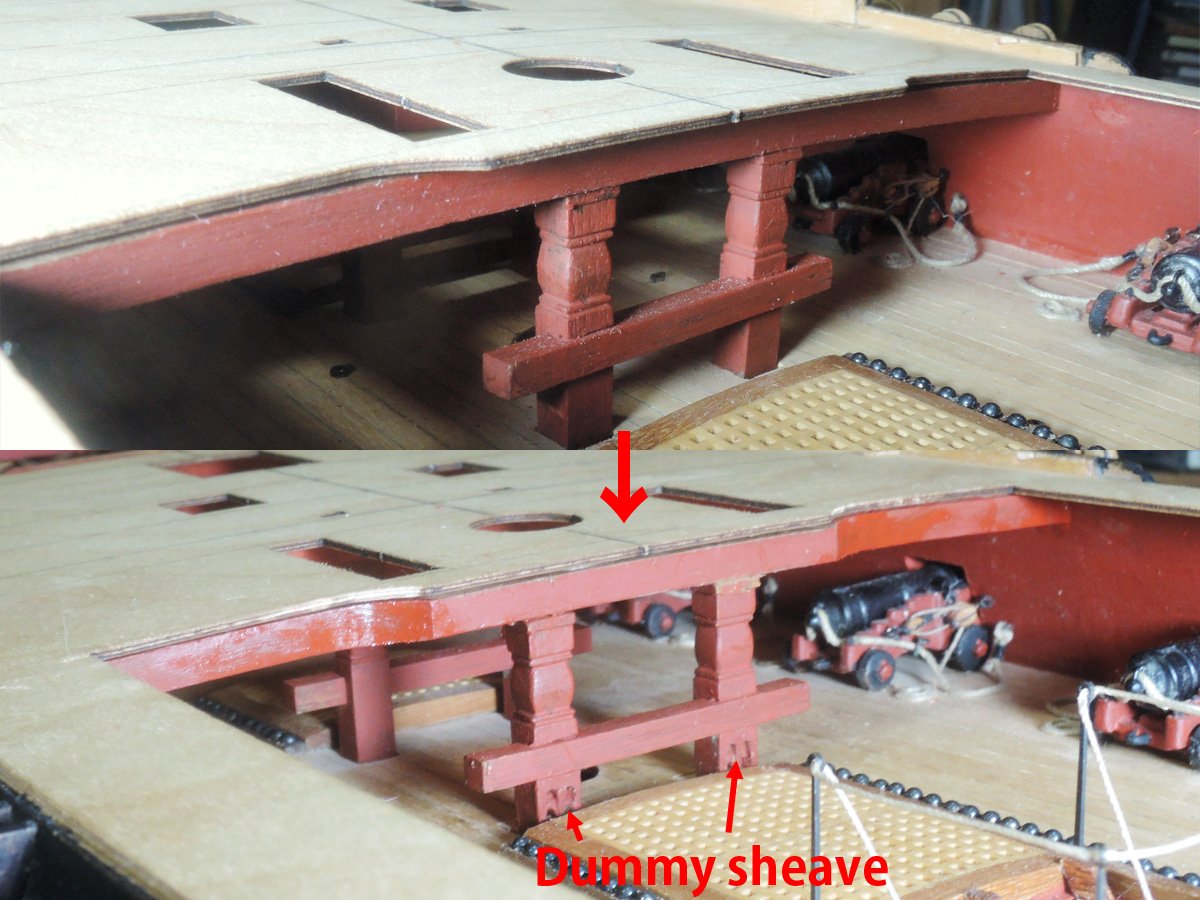
A pair of 3 mm walnut is glued both ends of beam, and shape them using quarterdeck baseboard as template.
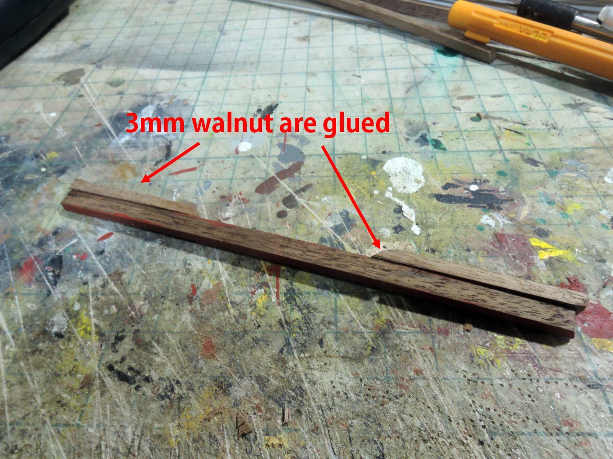
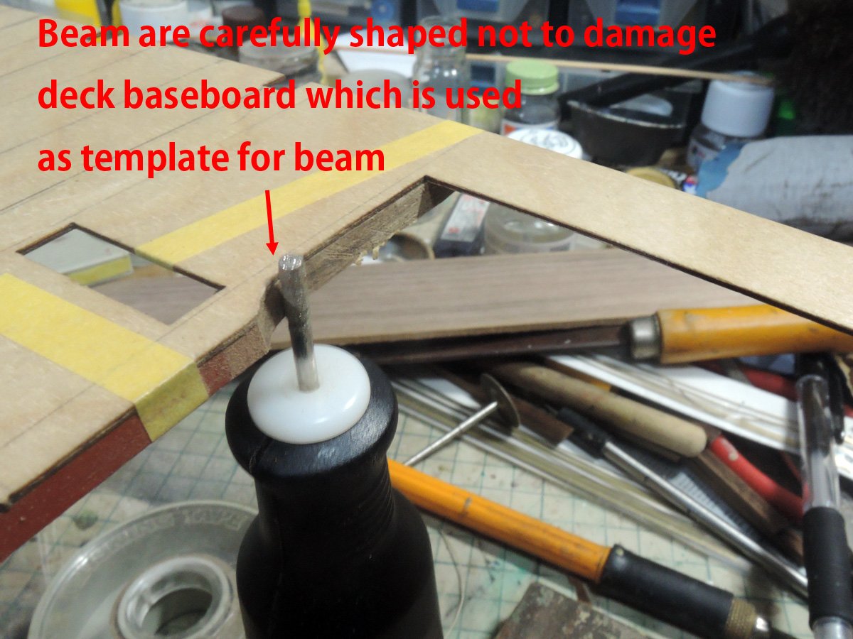
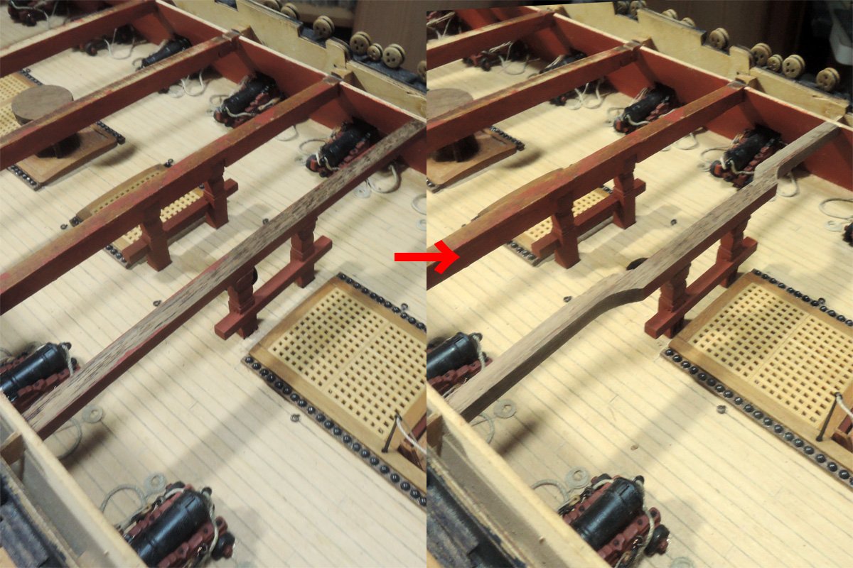
Remains of removing of main bits can be seen, but I made up my mind to neglect it😅
- GrandpaPhil, mtaylor, bruce d and 3 others
-
6
-
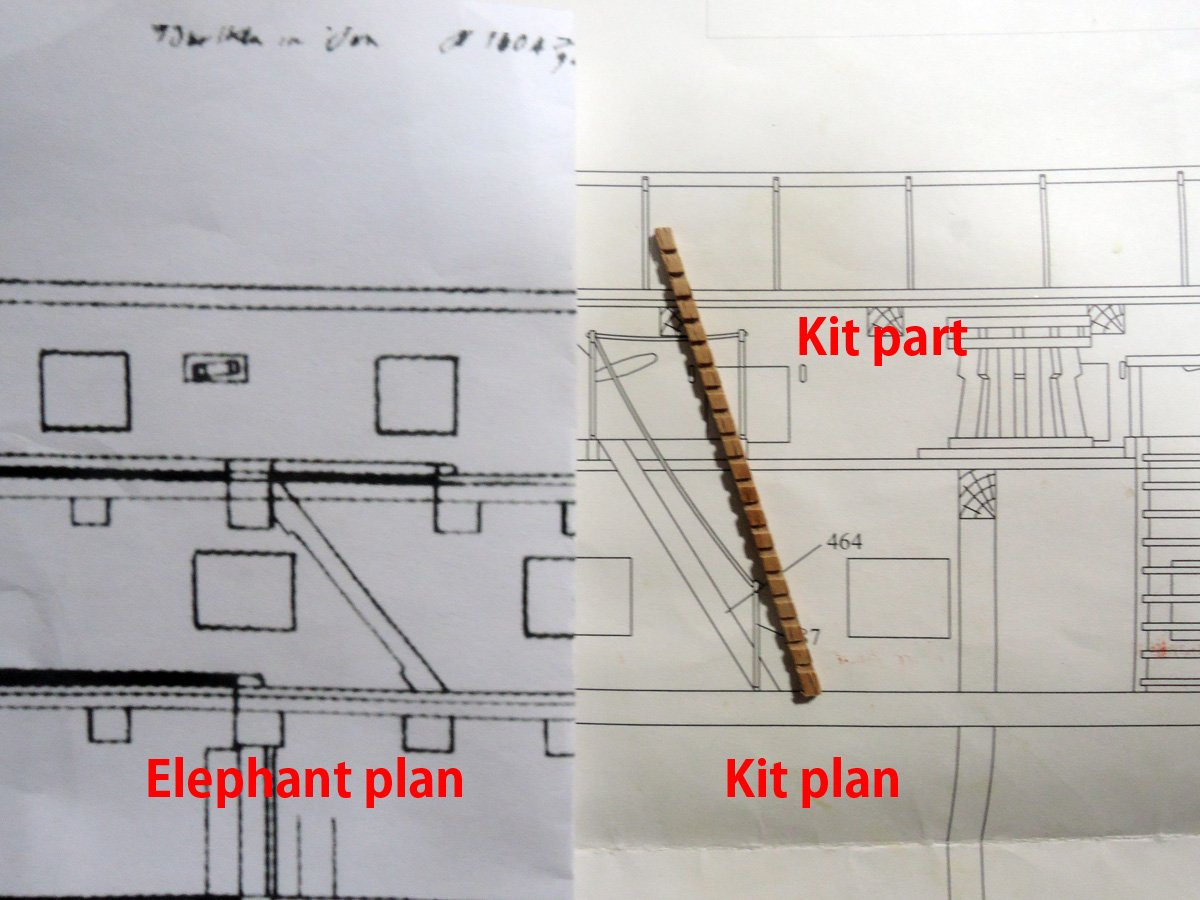
Ladders between upper deck and lower deck
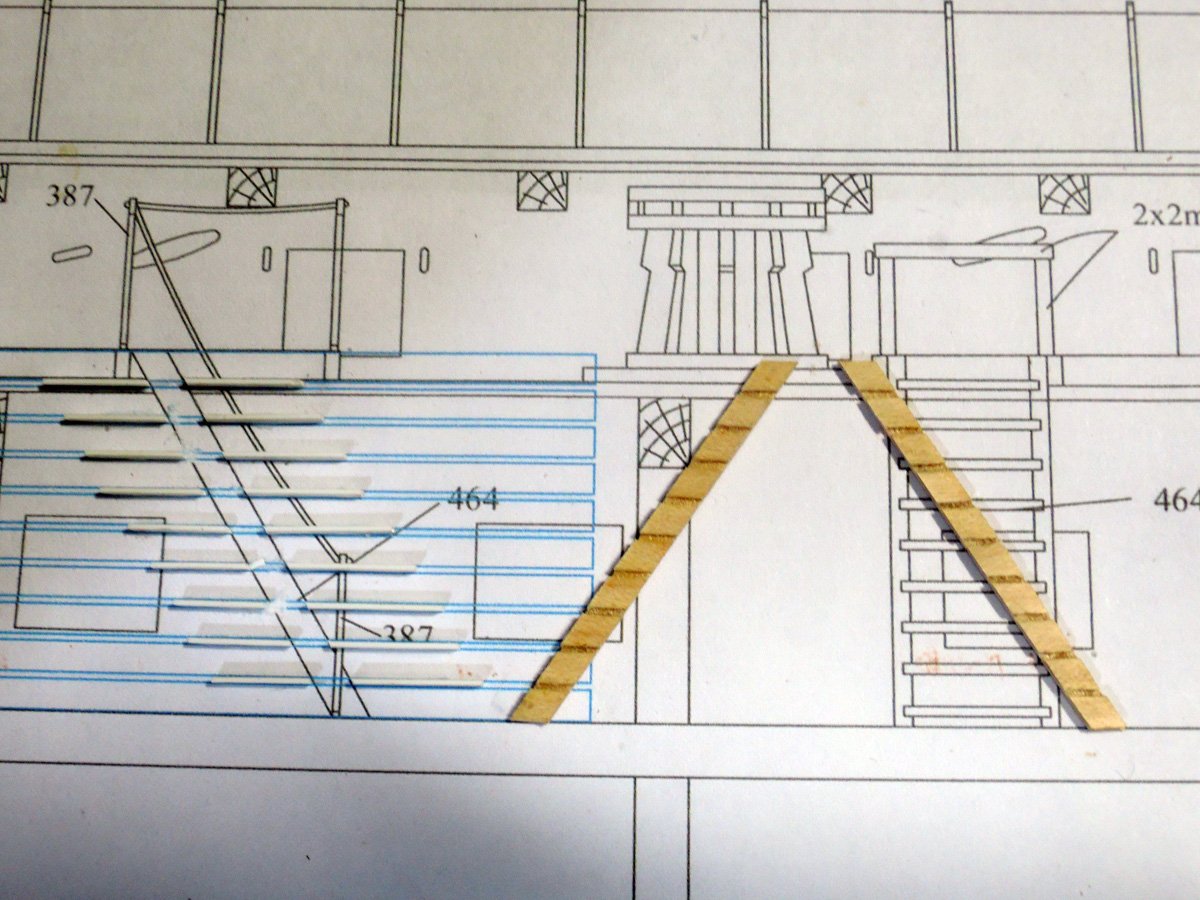
Although kit contains ladder parts, they shows steeper slope than both of kit plan or Elephant plan. So I determined to scratch build them.
I don't have table saw, I made side carriages by laminating. I scanned kit plan and draw lines equal intervals with Adobe Illustrator again. They are printed and used as jig by gluing guide of 0.5 mm plastic strip. I prepared jig only for one side, but I laminated horizontal strip with slightly longer length than required, another diagonal strip is glued onto another side of laminated components, then carefully divide them to 2 separated side carriage parts. Material of them are 0.5 x 3 mm maple strips. They are basically deck planking materials, but I used them because I have surplus numbers of them.
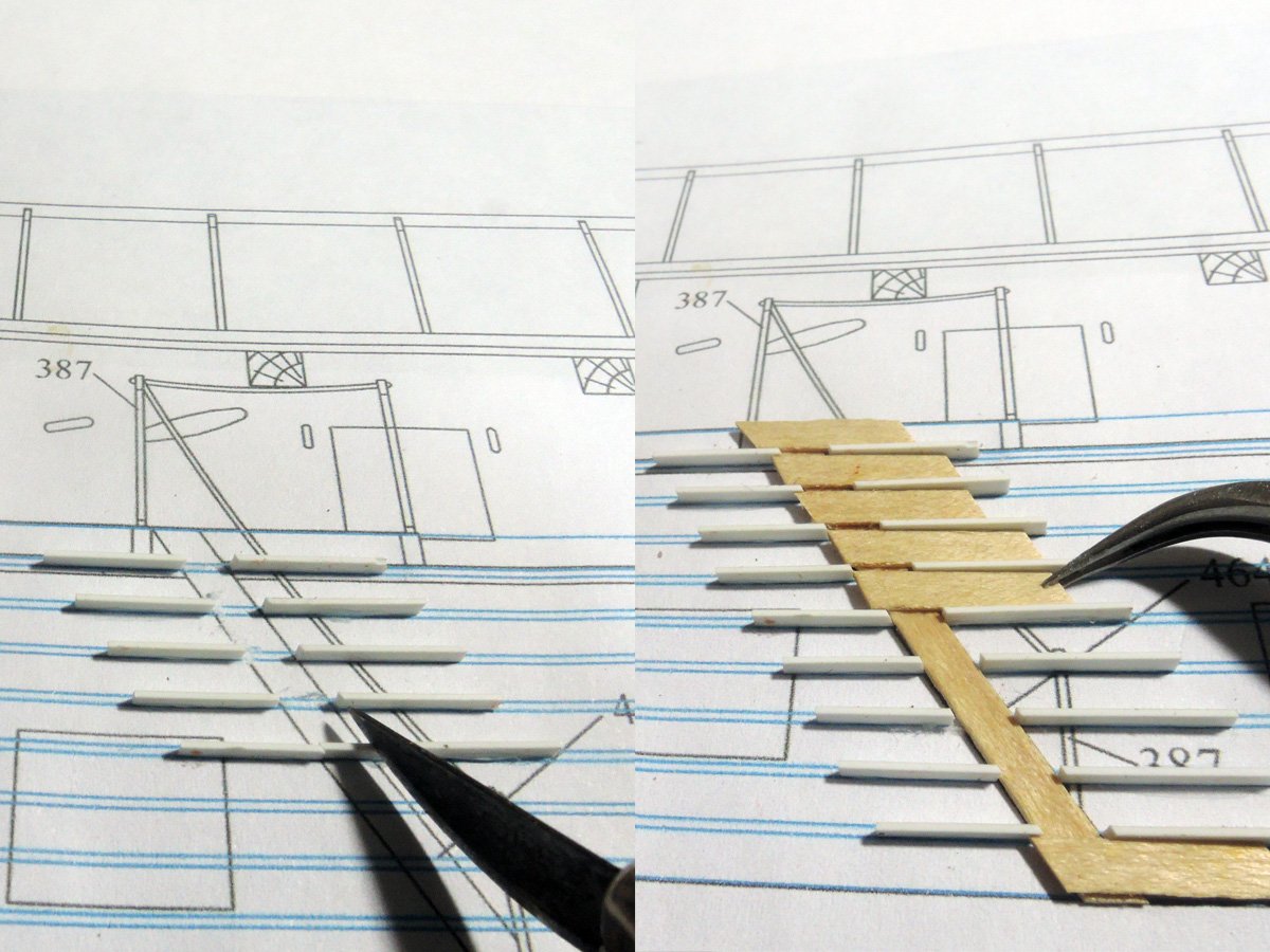
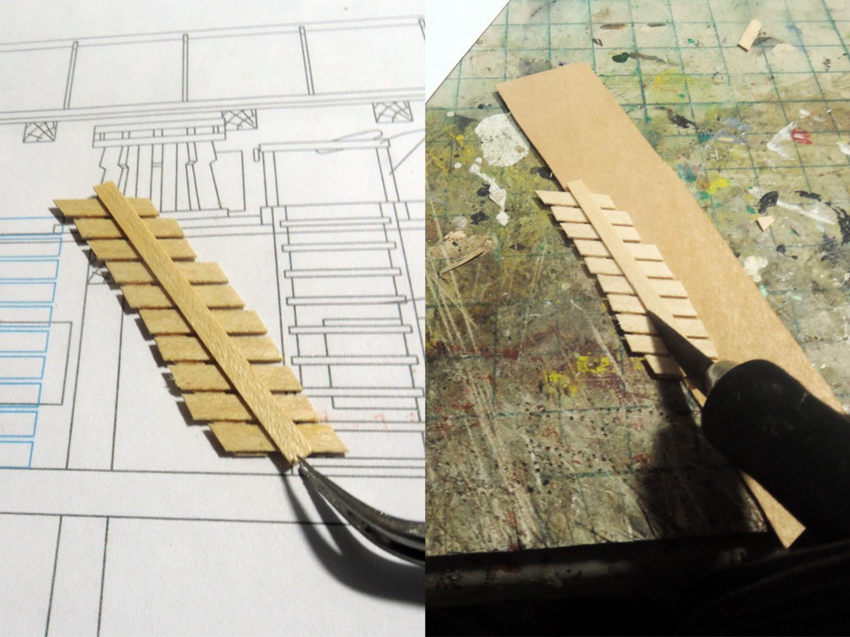
Treads are also 0.5 x 3 mm maple strips. Firstly length of uppermost and bottom tread determined by actual parts matching then glue them to side carriage.
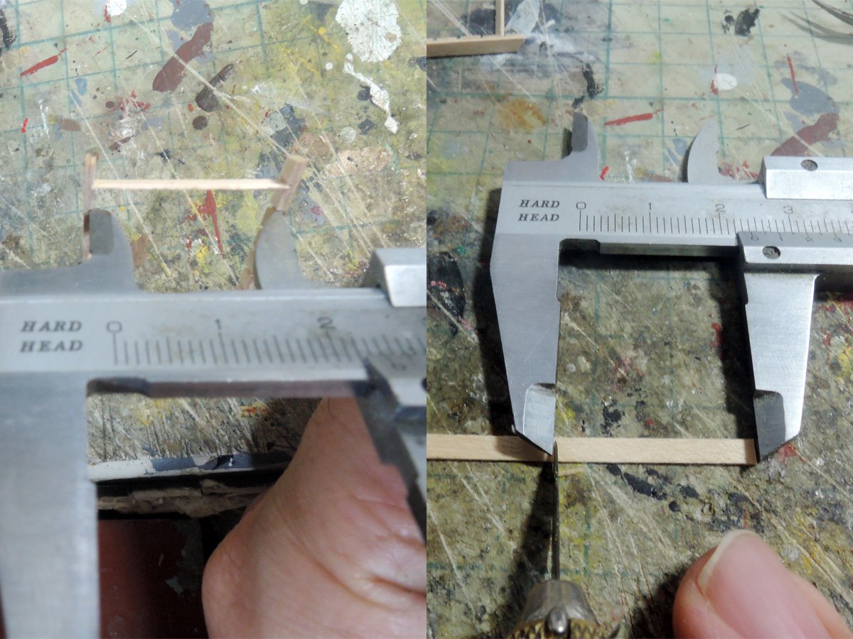
Length of other treads are determined measurement between each side carriages with calliper.
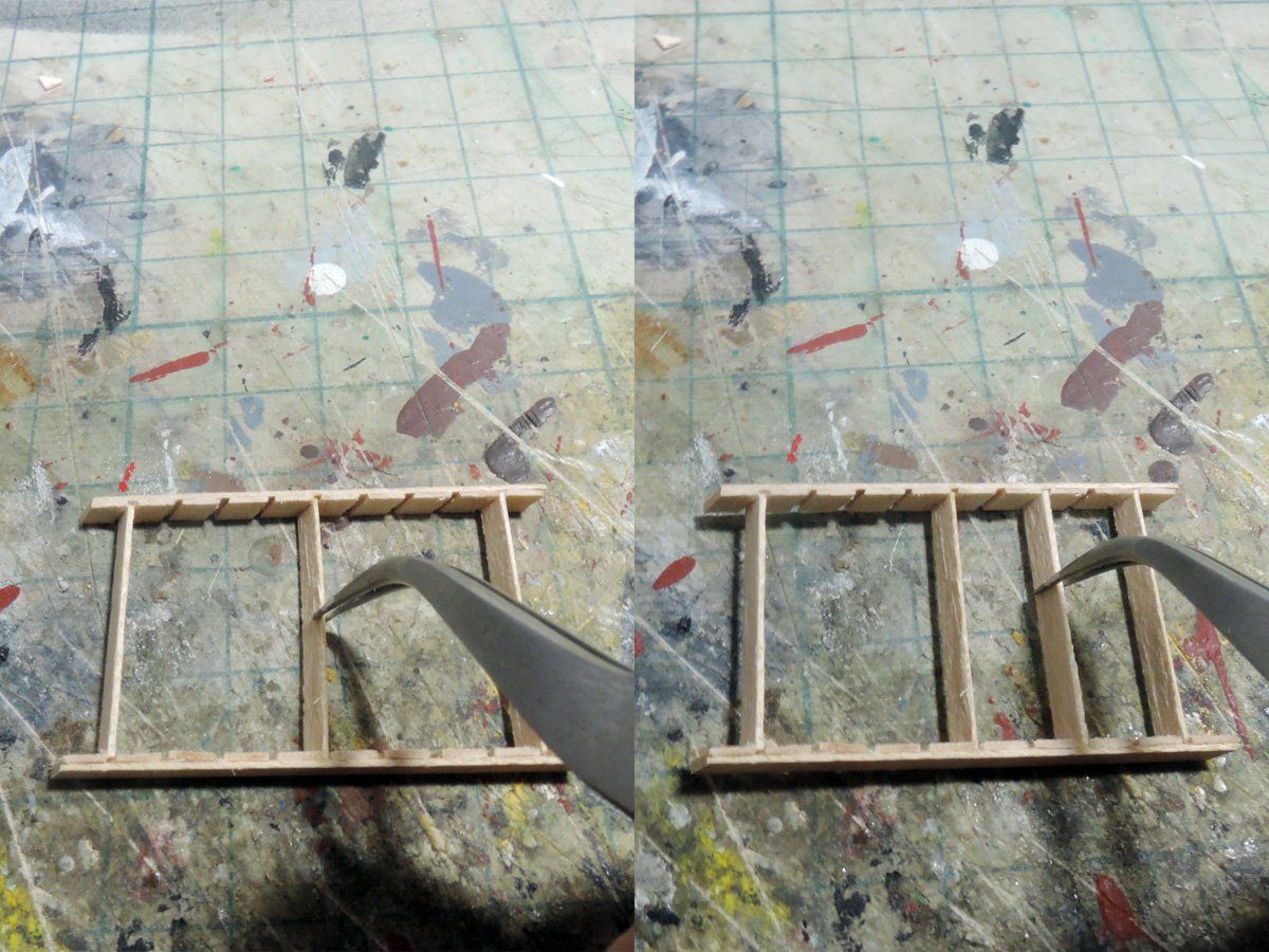
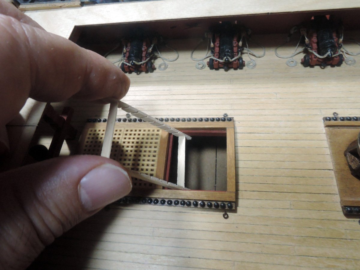
Main ladderway is added with centre carriage by inserting other pieces of wood between each tread.
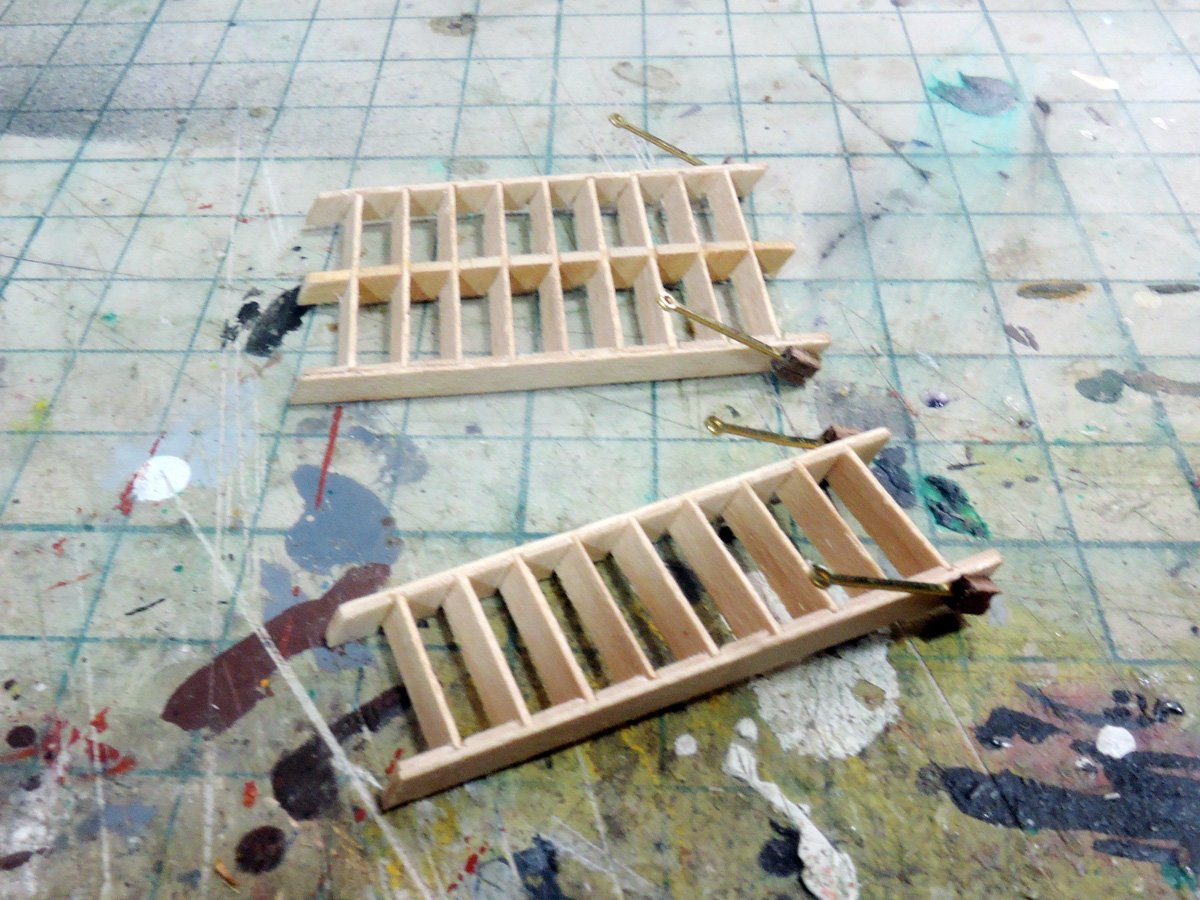
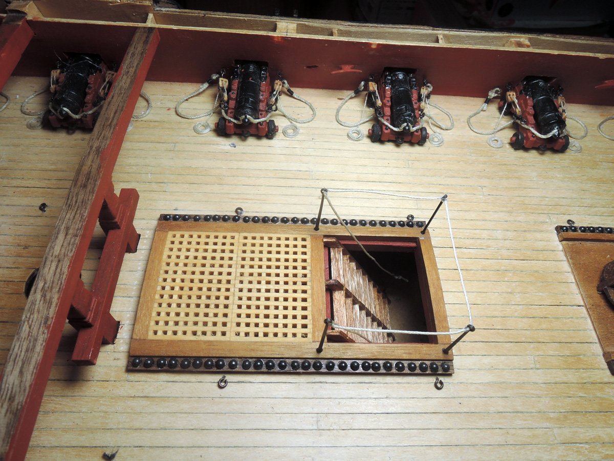
Completed ladders were stained and fitted between decks. Handrail stanchions are kit PE which is chemically blackened. It is difficult to fit them to lower deck. So I fitted them heel of side carriages with holding wood piece.
Handrail rope is prepared with excessive length. I placed one of lower pair of stanchions to its holder, rest 5 stanchions are reft free. I pass rope through holes of all 6 stanchions. One end of rope on fixed stanchion is knotted. 5 stanchions are fitted their places after ladder is located. Point to be knotted of another rope end is determined and this last stanchion is once removed, rope end are knotted, then finally this last stanchion are fitted to its holder.
- GrandpaPhil, chris watton, James H and 6 others
-
9
-
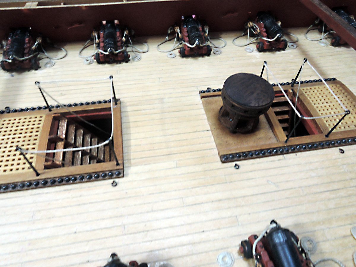
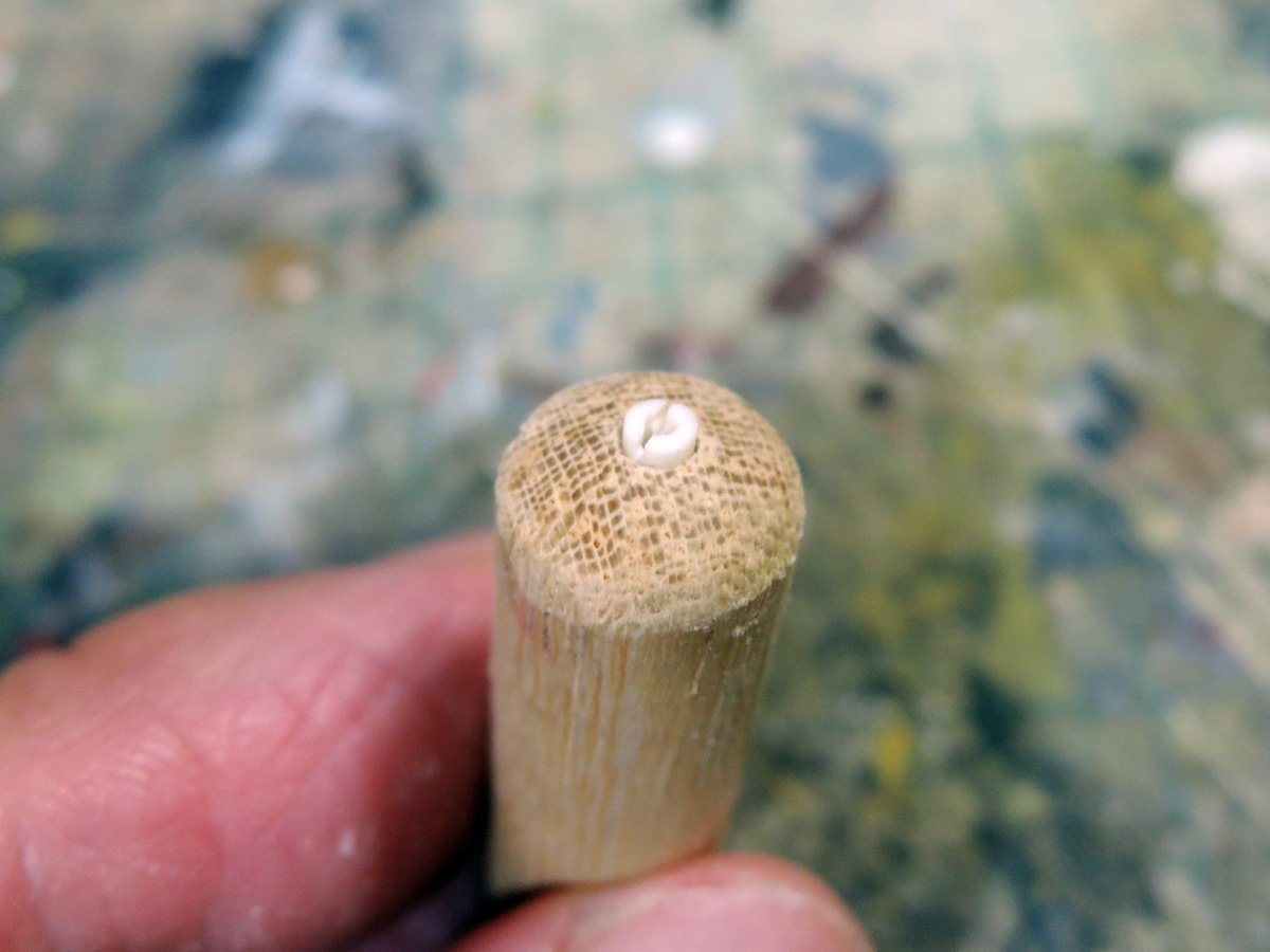
Capstans
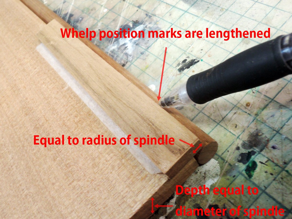
Capstans are basically made of kit parts. Firstly whelps should be glued with equal intervals around spindle. I divided length of circumference of spindle by numbers of whelp, namely six and prepared scale of this numerical value. They are drawn with Adobe Illustrator.
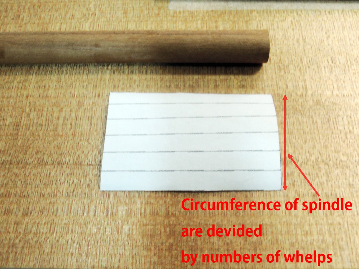
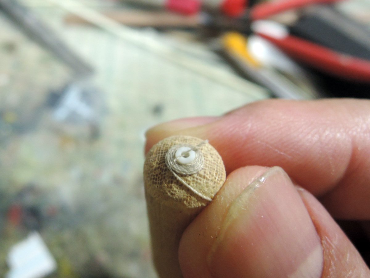
I rolled this scale to spindle then marked according to scale.
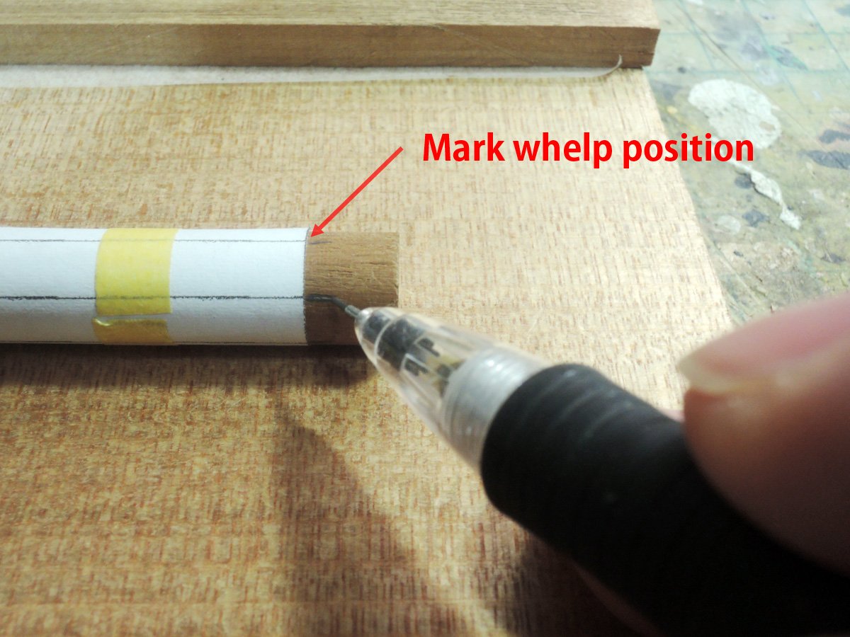
These marks are lengthened by using simple jig. Then whelps are glued carefully.
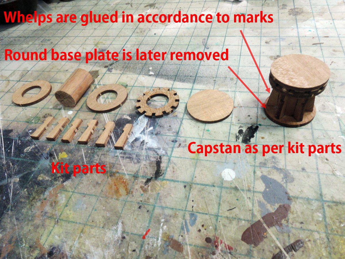
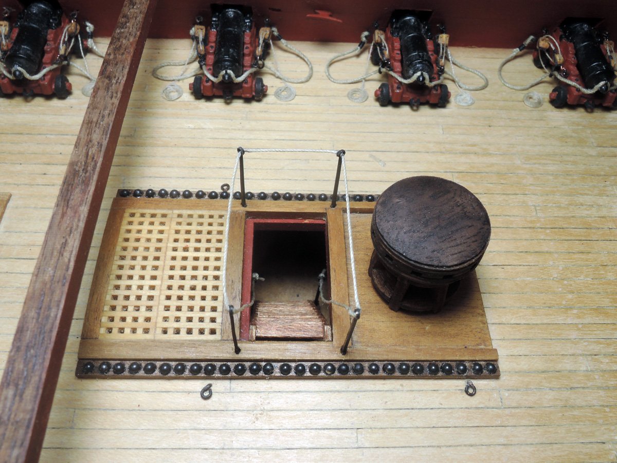
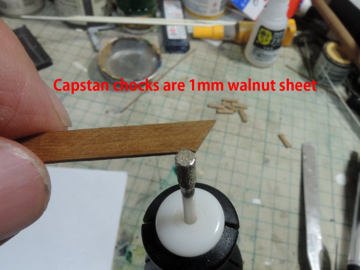
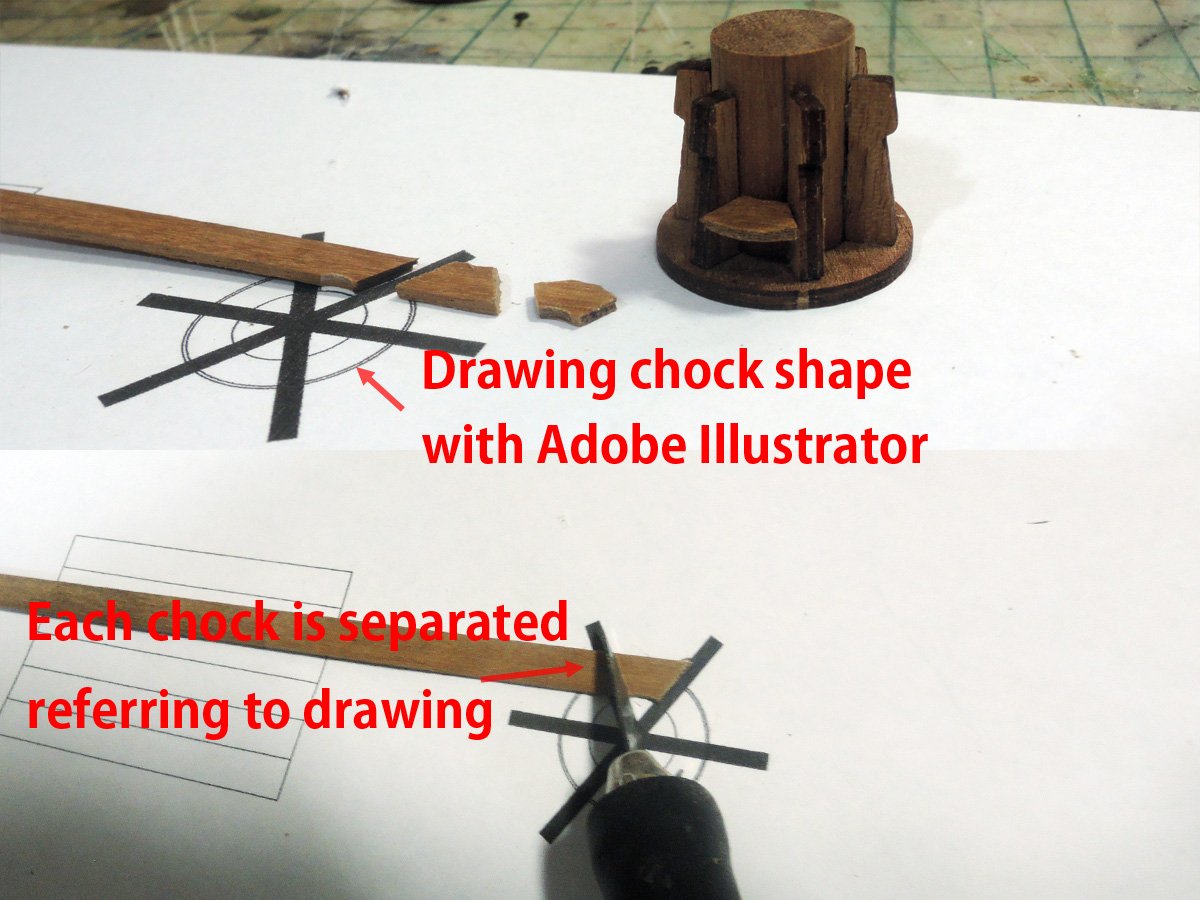
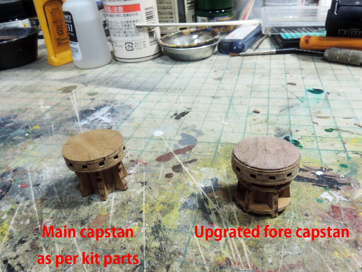
Aft capstan is almost straight built of kit parts but forward one is upgraded because they can be seen well through opening of waist. Chocks and drumhead top are added. Shape of chock is also drawn with Adobe Illustrator.
They are cut from 1mm walnut strip. Then they are glued between whelps and shaped.
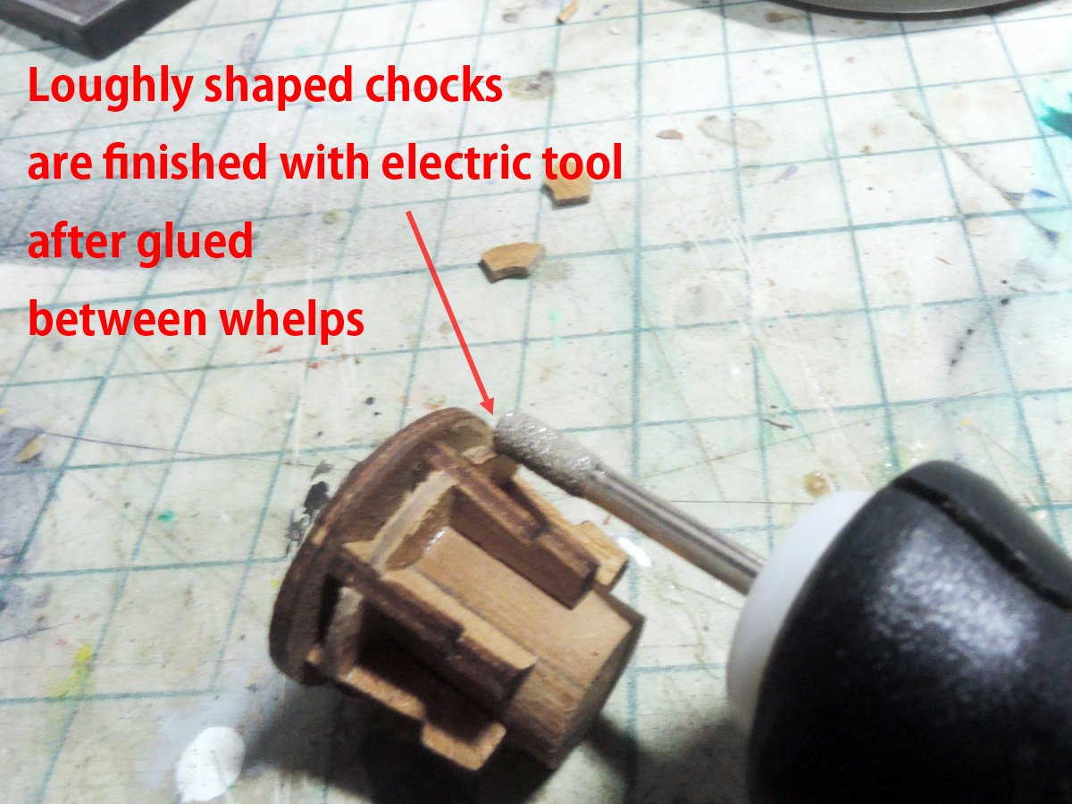
Disc slightly smaller than drumhead is cut from 1.5mm walnut and rounded to give slope then glued onto drumhead.
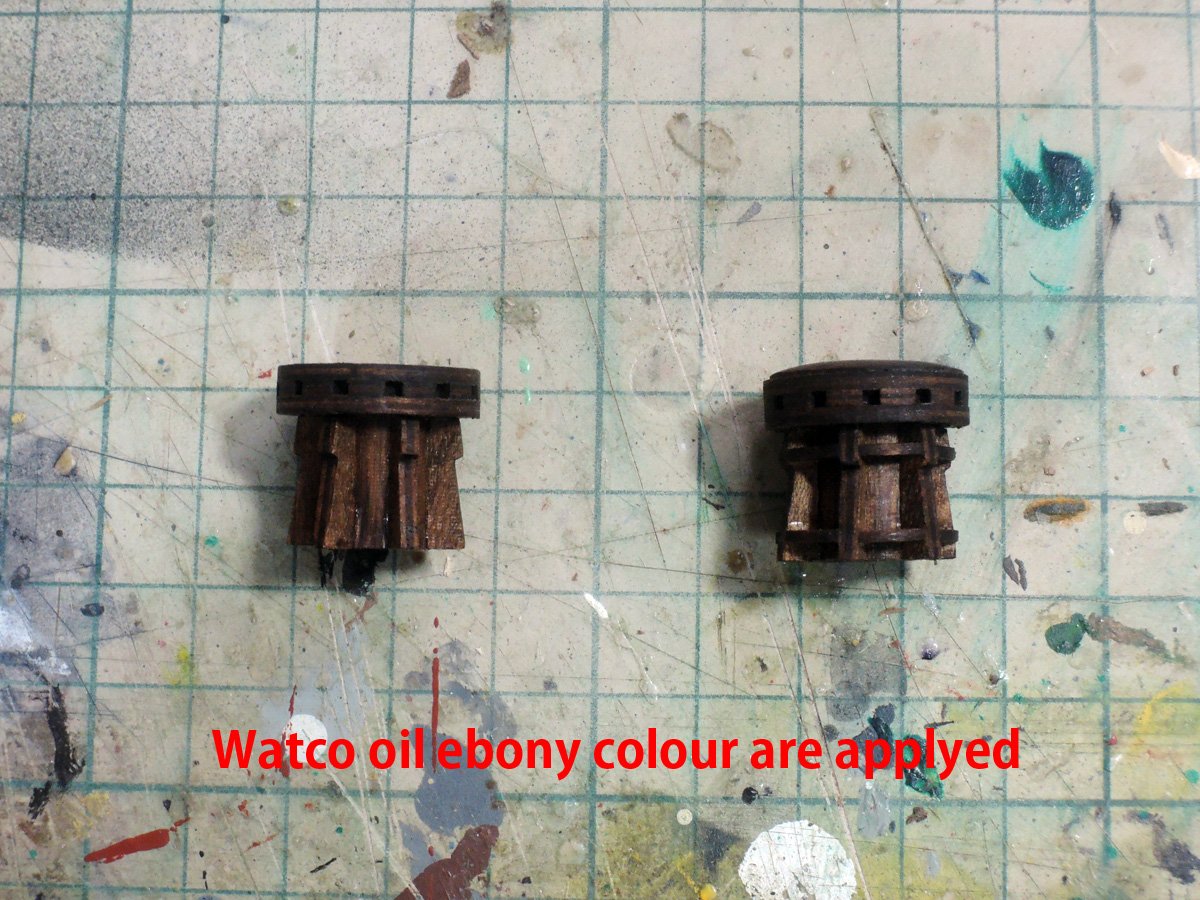
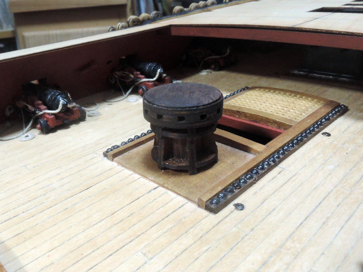
BTW, I removed round base plate of capstan because I already glued rectangle base plate onto deck.
- James H, Roger Pellett, mtaylor and 3 others
-
6
-
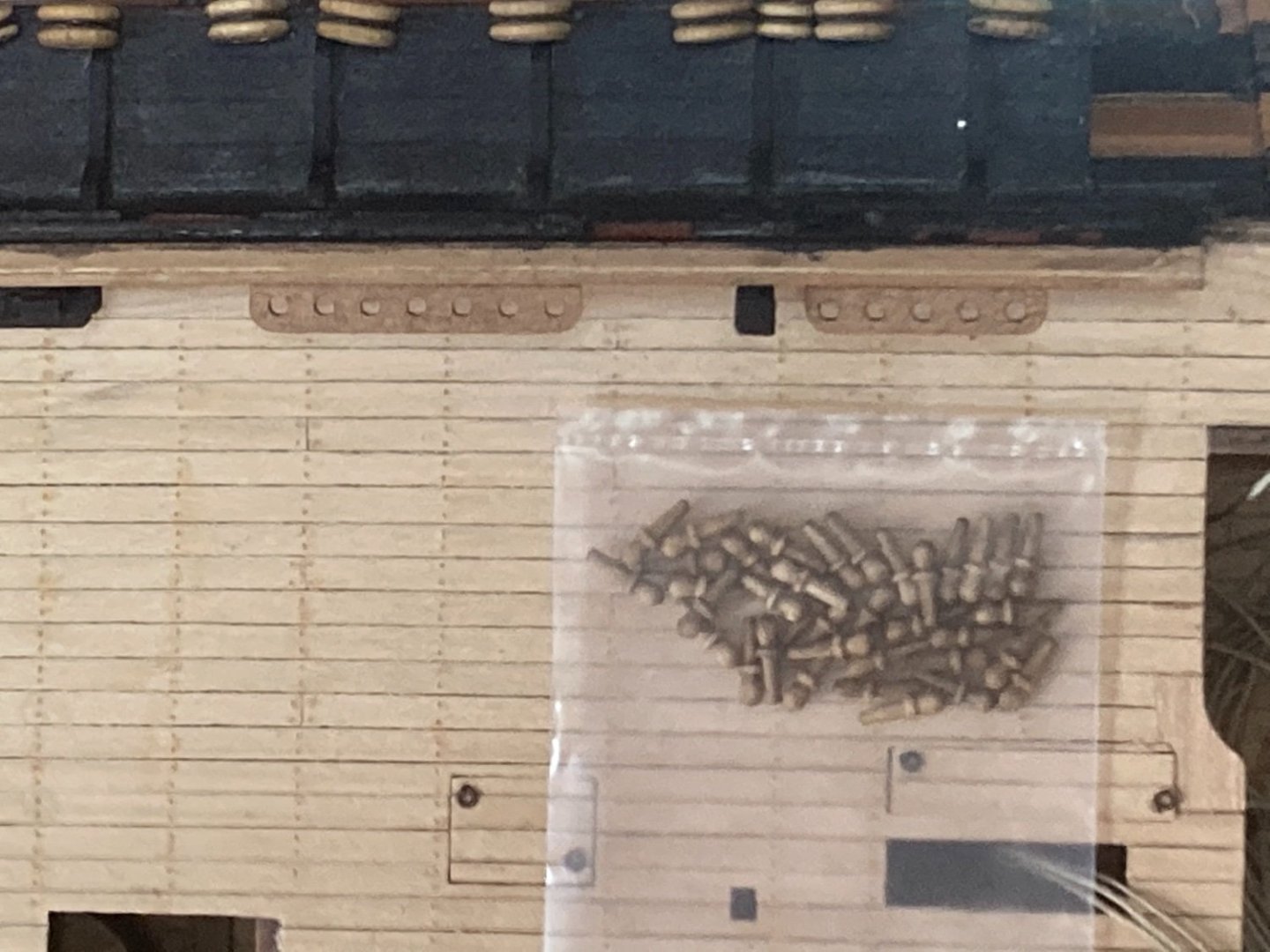
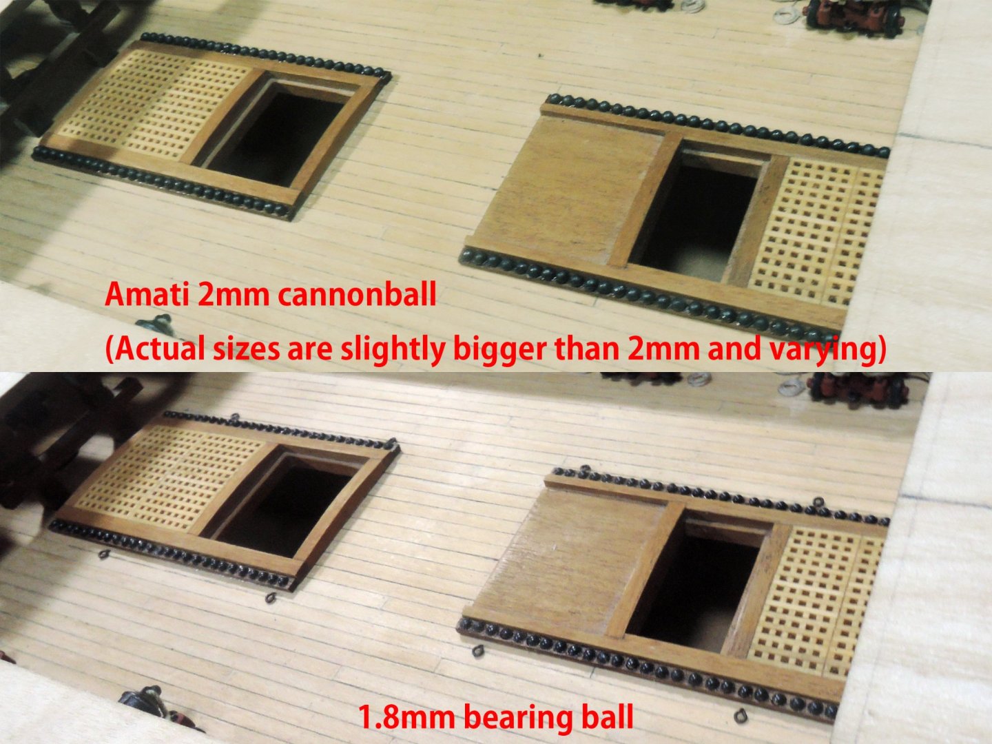
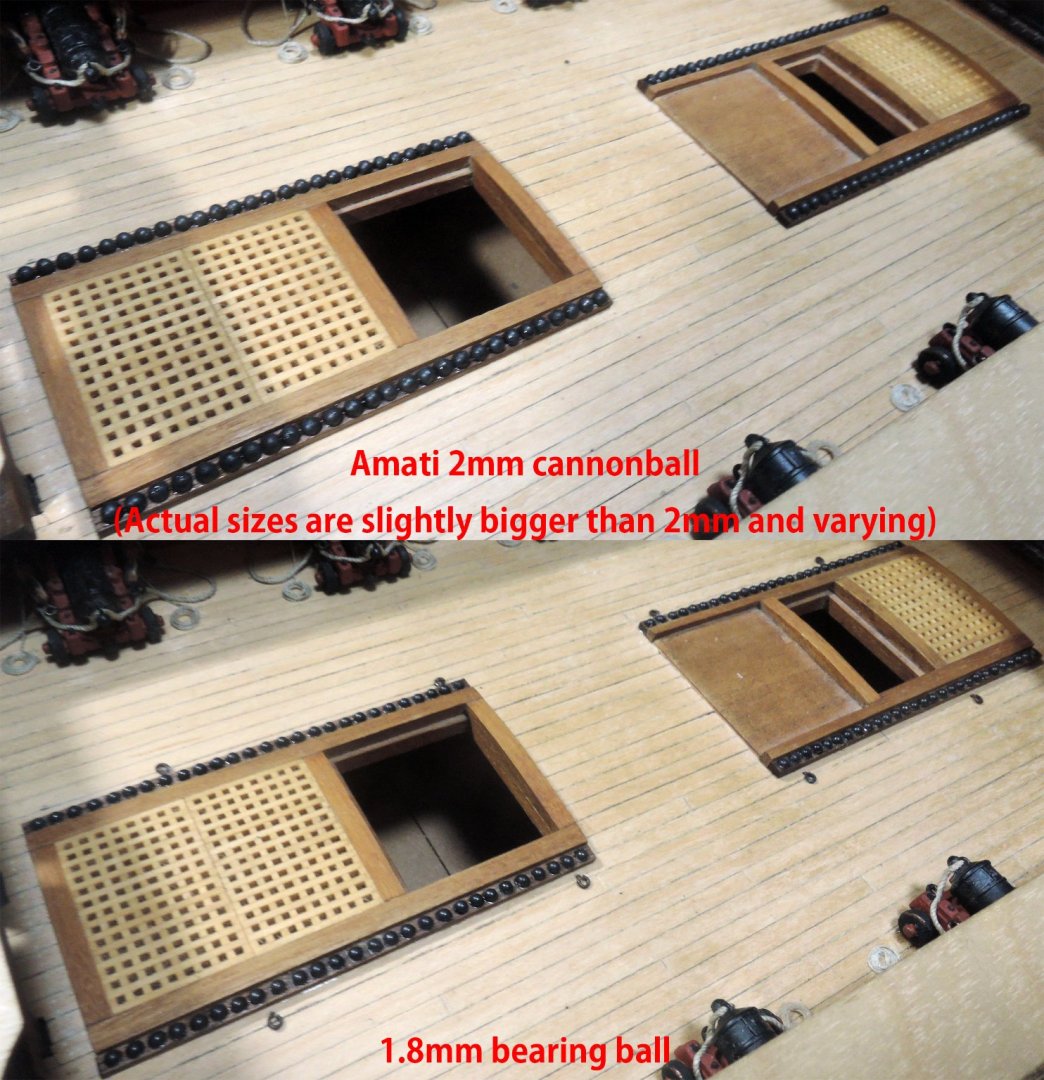
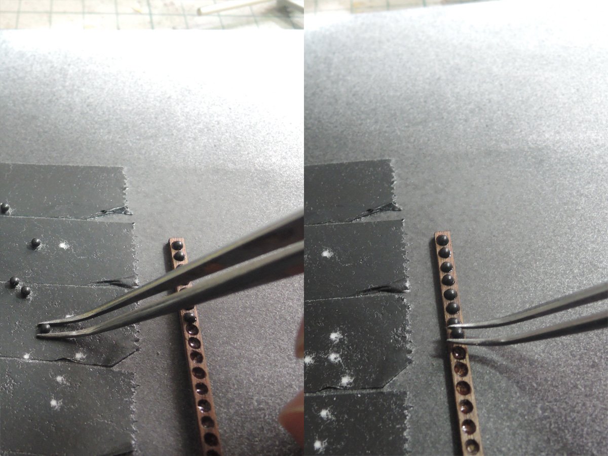
Cannonballs and shot garlands
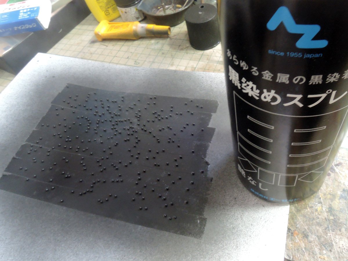
Firstly I tried using kit cannonballs but it seems to be slightly bigger. As far as my research, diameter of 18 Ponder cannonball is 5.04 inch and it became approximately 1.8 mm at 1/72 scale. Amati cannonballs are provided as 2 mm size, but their actual sizes are slightly bigger than 2 mm and varying little by little. Finally I determined to use 1.8 mm baring ball as 18 Ponder cannonballs. They are blackened with AZ Blackening Spray.
Sizes of shot garland are varying from one reference source to another. I took length between holes from HMS Euryalus book published from Sea Watch Books.
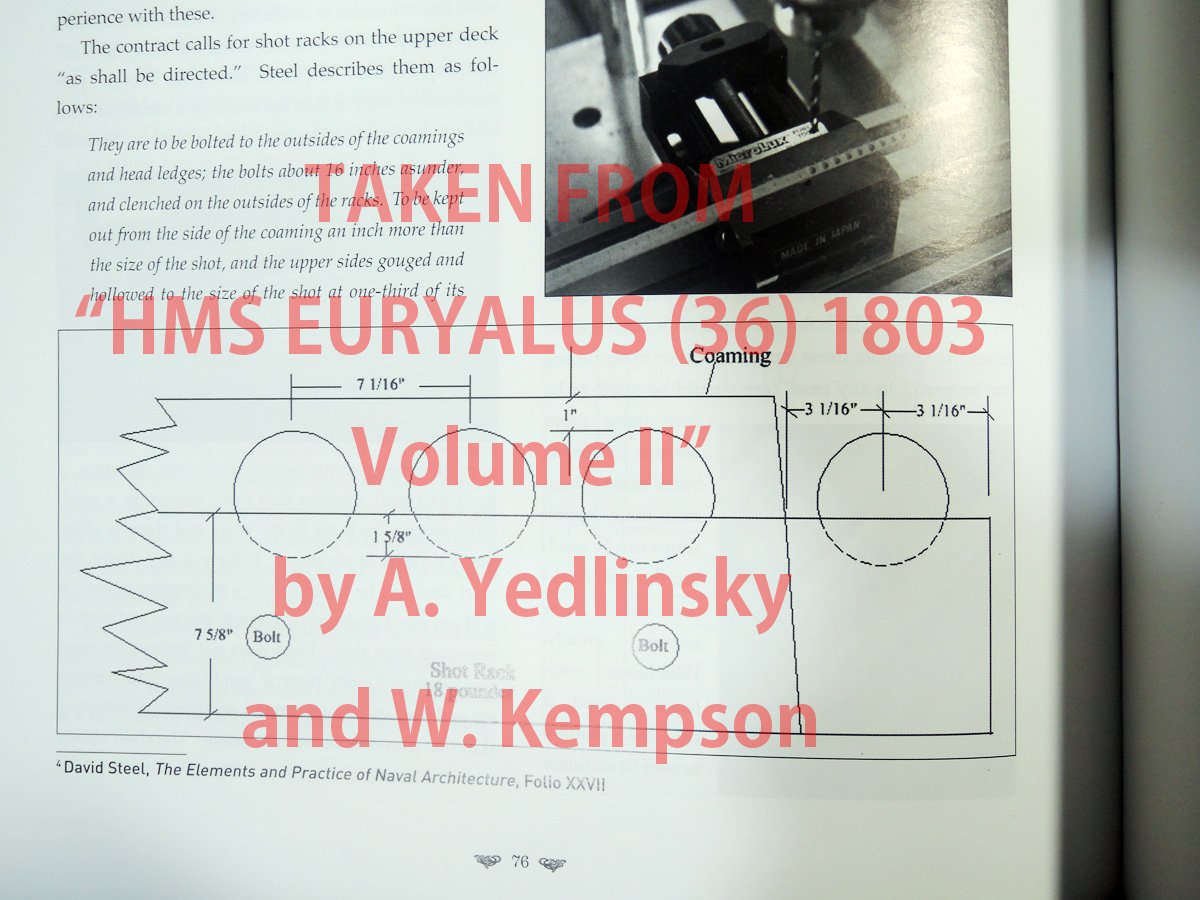
Sizes of garlands are referred to Goodwin's "Construction and fitting". Width is 2.5mm and depth is 1.5mm. They are made from walnut.
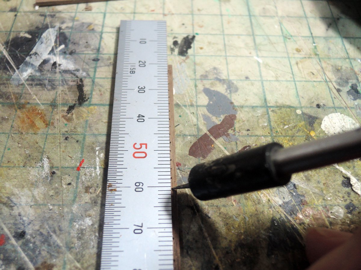
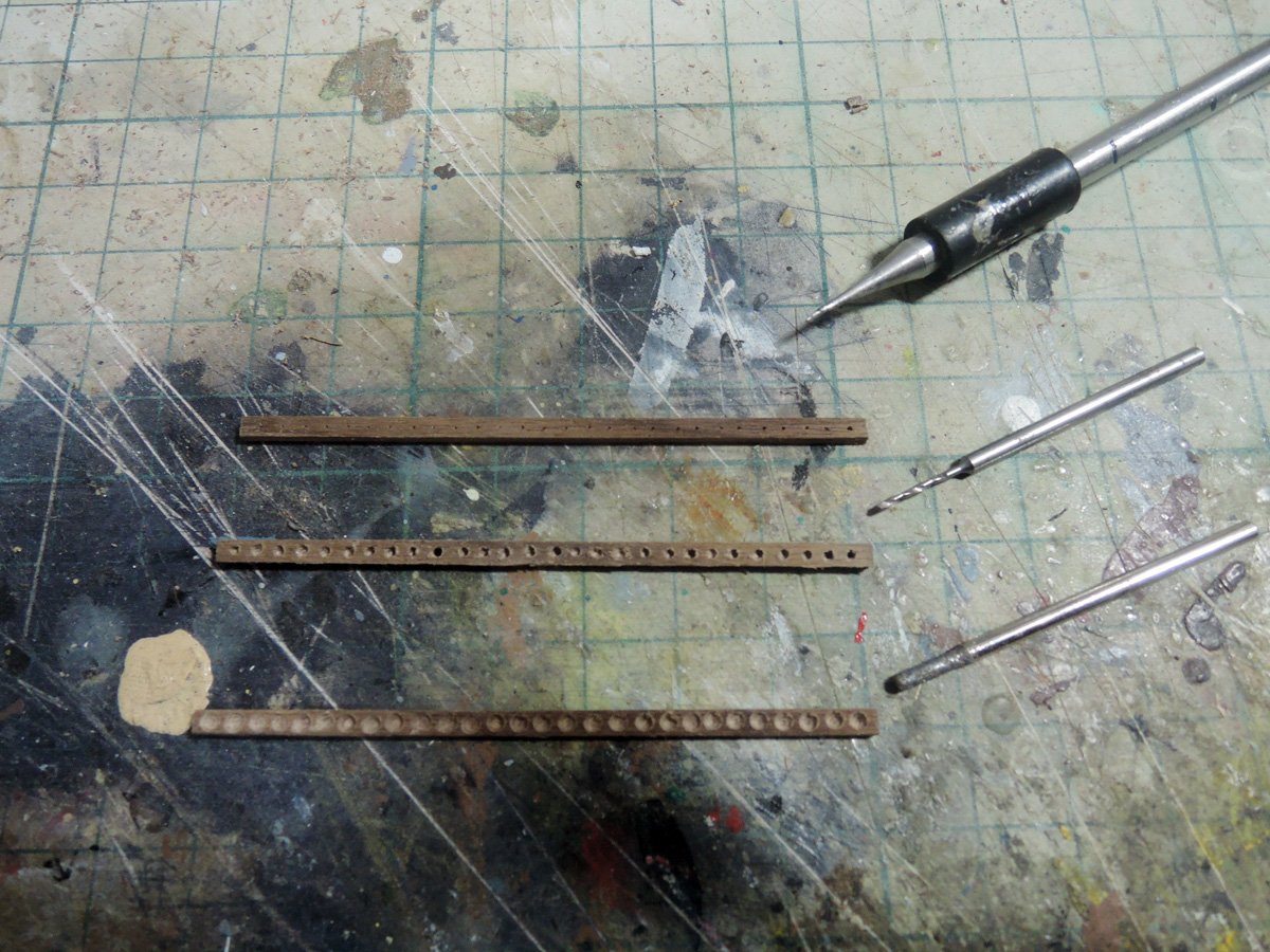
I don't have drilling machine with automatic feeder, so I have to drill holes with hand operated machine. Intervals between holes aren't equal, but I have to accept them.
- bruce d, mtaylor, Roger Pellett and 2 others
-
5
-
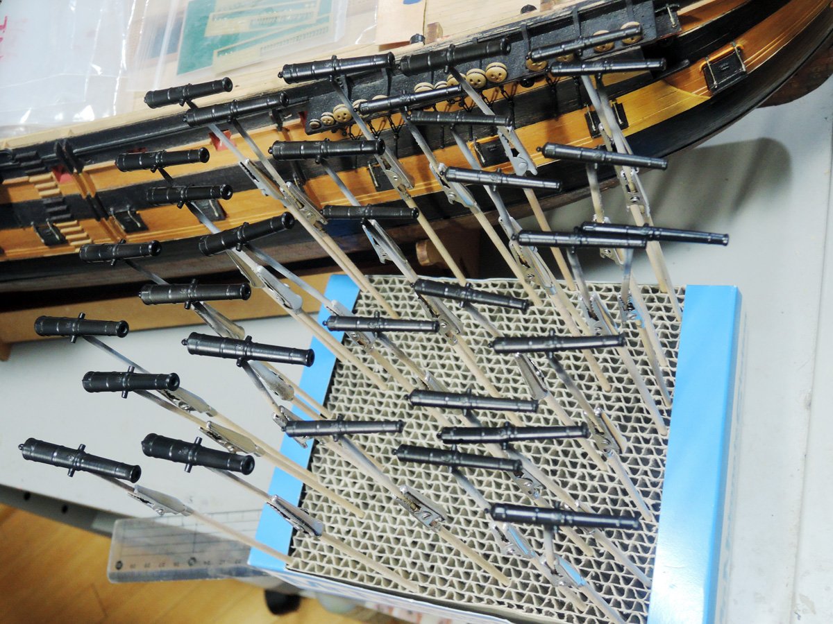
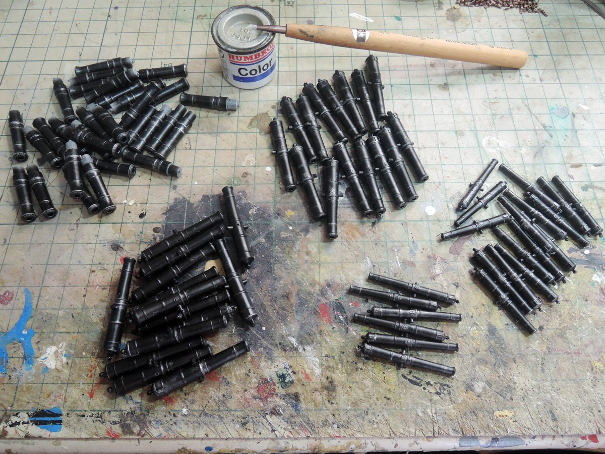
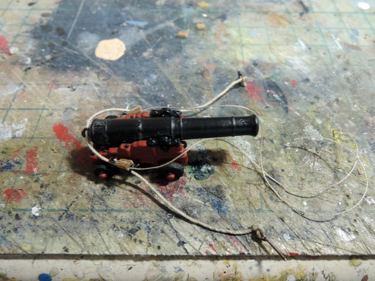
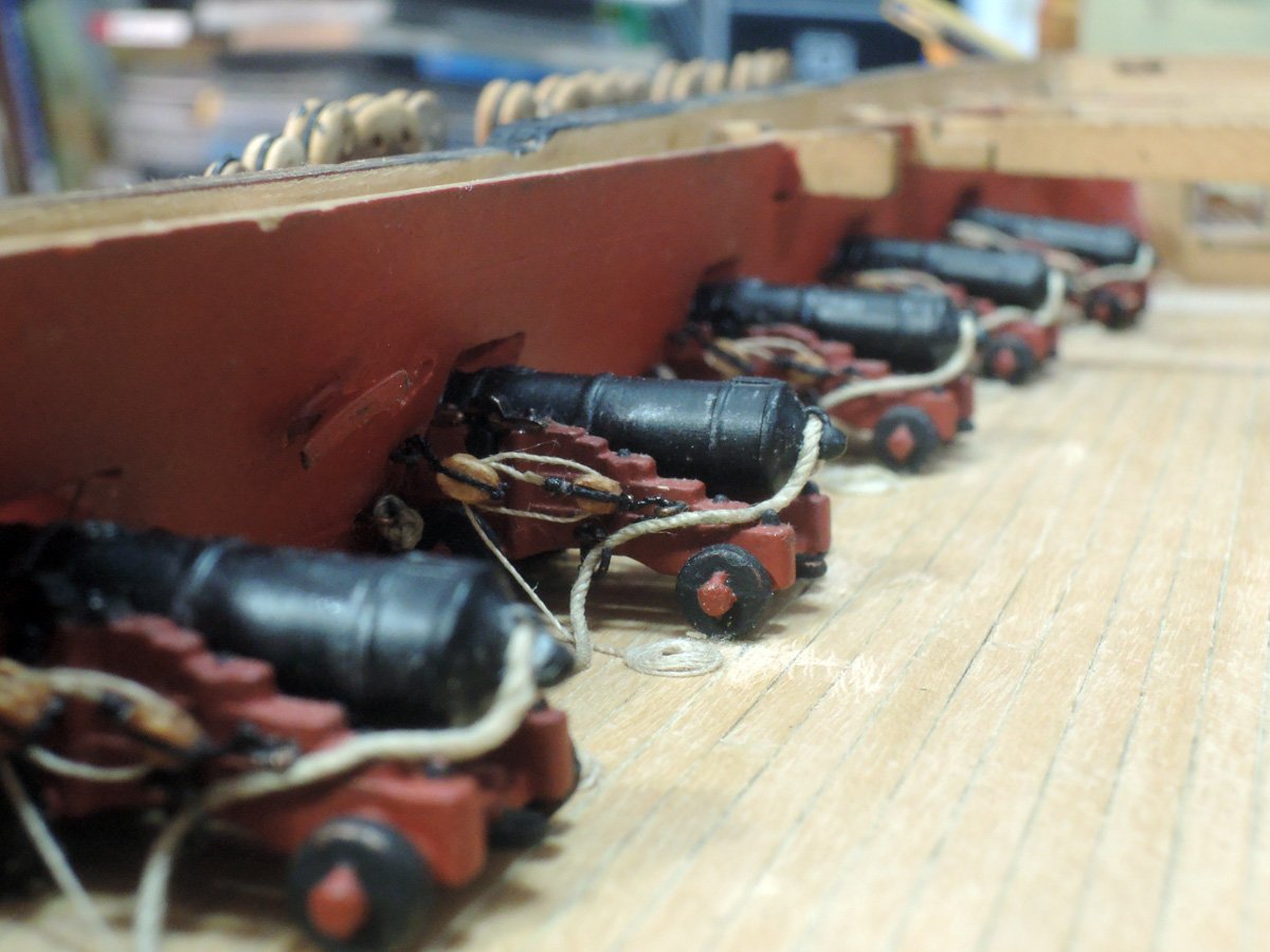
18 Pounder Guns
As I posted previously, guns were specially 3D printed by one of my fellow modellers.
Kit PE monograms are CA glued to guns, but I didn't use flintlock PEs because firing lanyards are lost from some of them. I sprayed primer, then sprayed Mr. Color semi gross black, and finally dry brushed with Humbrol silver.
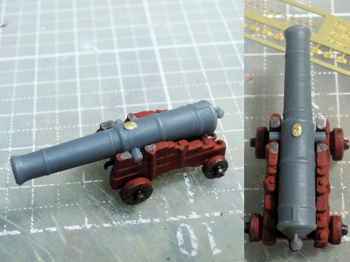
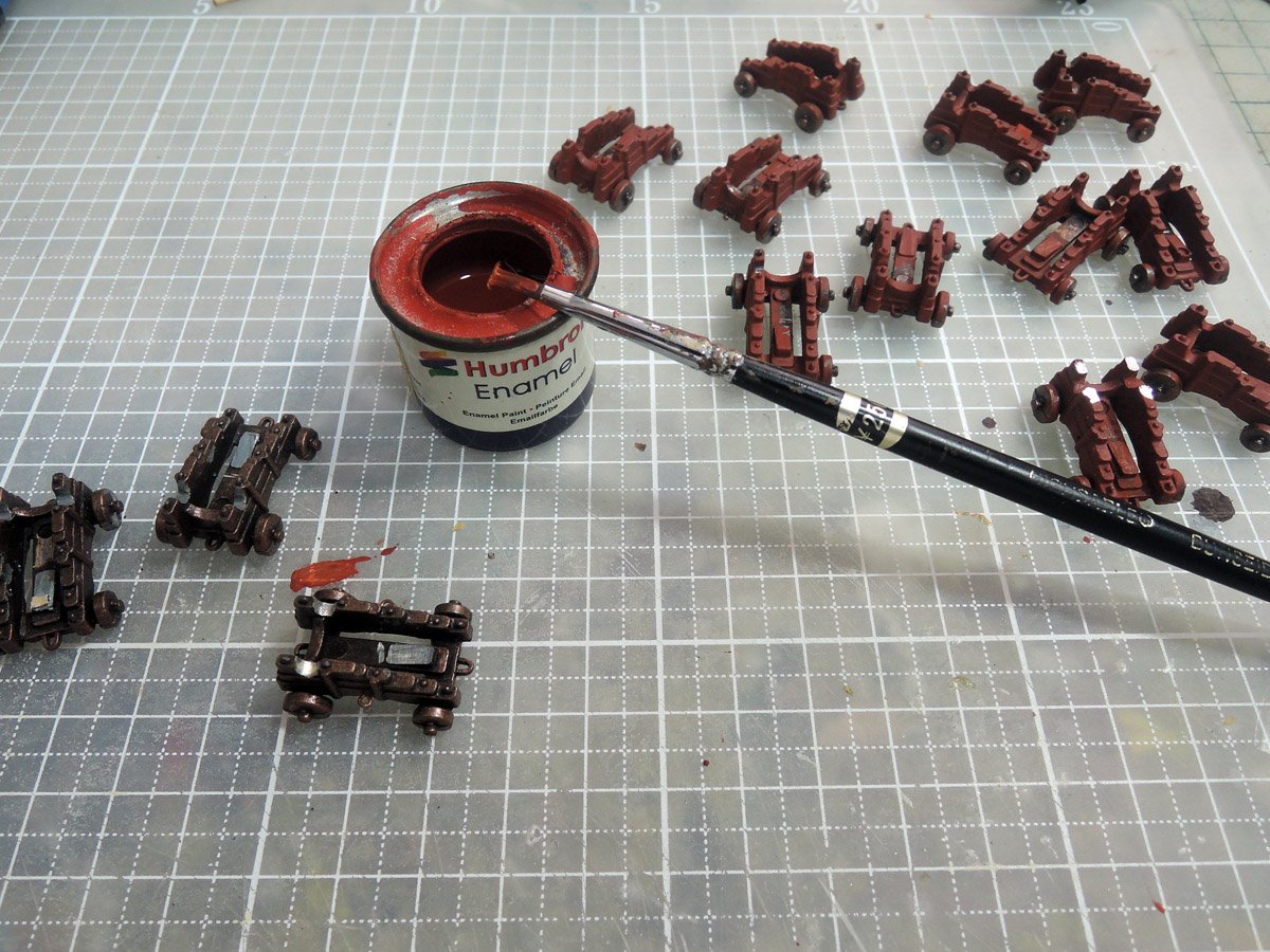
Carriages are kit diecast parts. Although diecast carriage of Amati isn't best ones and much more superb carriage can be obtained through market or scratch built by oneself, they can be seen acceptable by applying paints and gun tackles.
It was hard task to open holes for eyebolts for gun tackles, but they were done by help of electric drill. Red paint is Humbrol enamel mixed with proportion suggested in kit instruction. Wheels are also painted with Humbrol mat black. Chemically blackened eyebolts are added after paints dried.
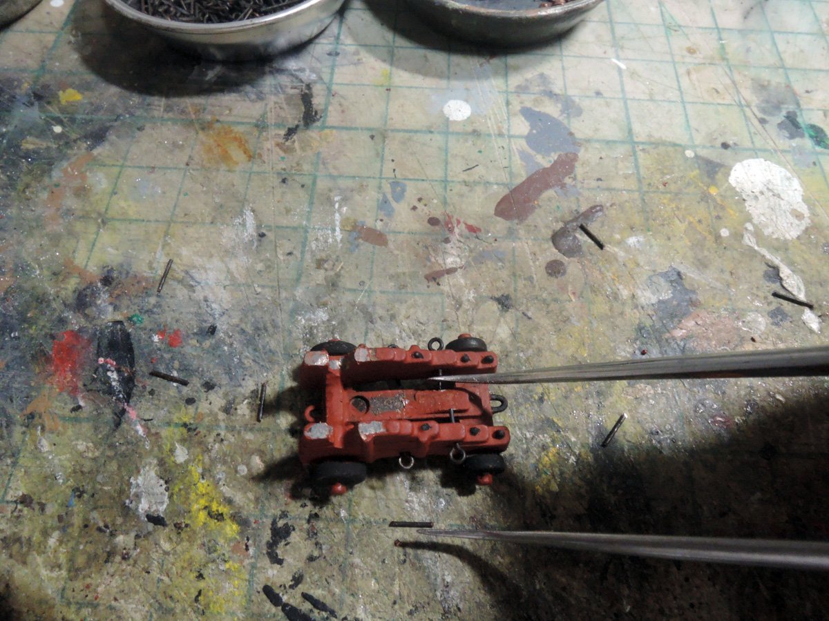
BTW, kit design is showing varying heights between deck level and gunport openings. Those of forward sections are higher, and those of lower sections are lower. As I posted previously heights of carriages are modified to protrude guns from centre of gunports.
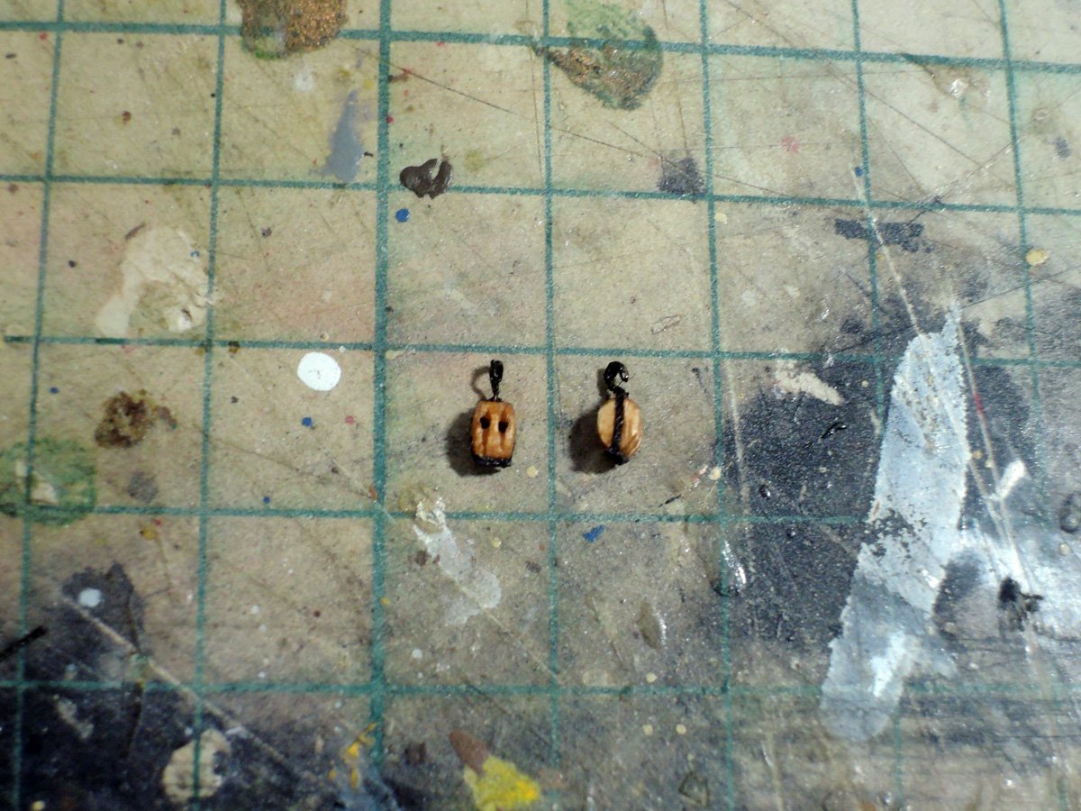
Gun tackle blocks are Amati parts, but their shapes are improved with PE saw and Urawa mini router.
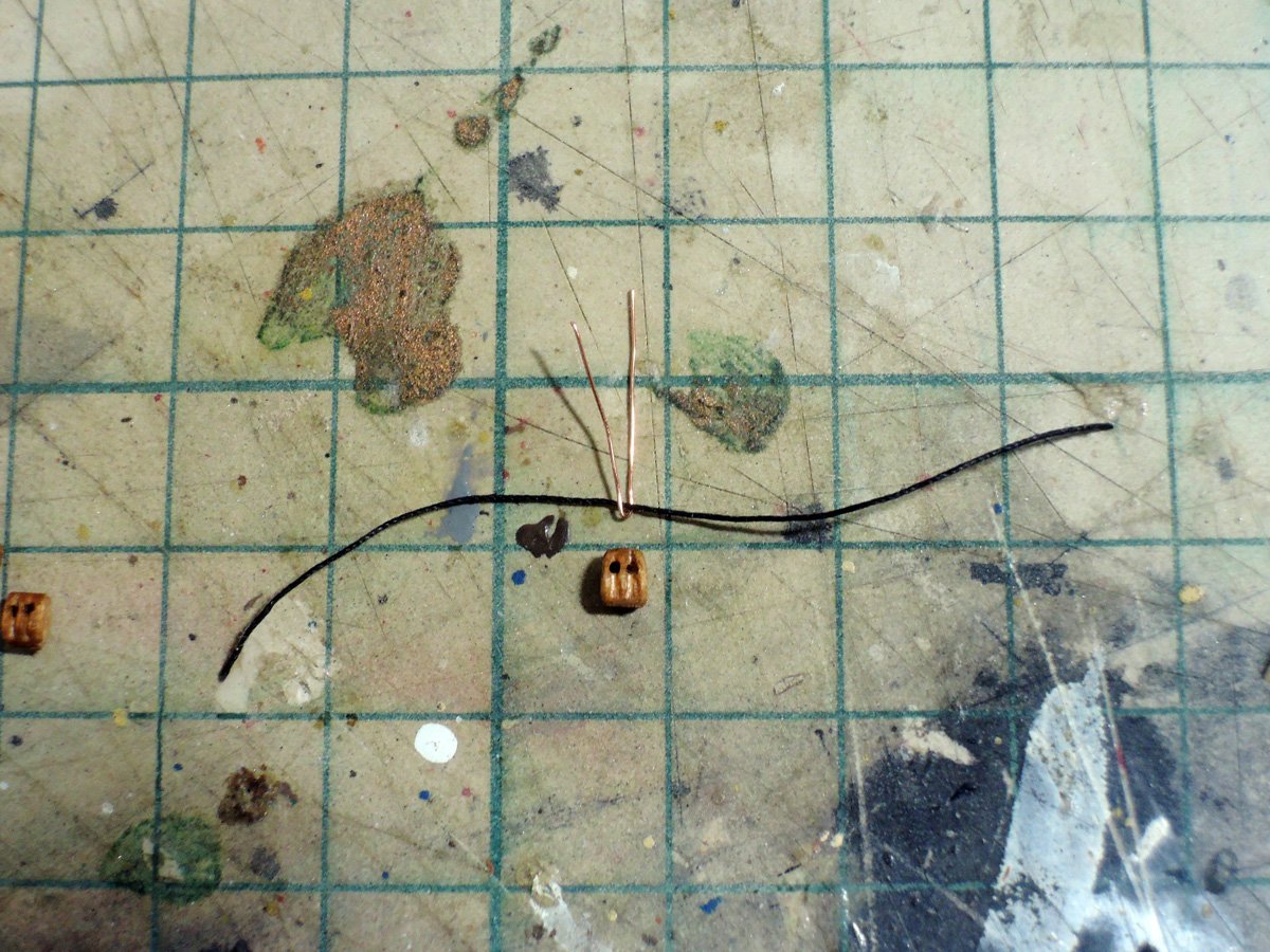
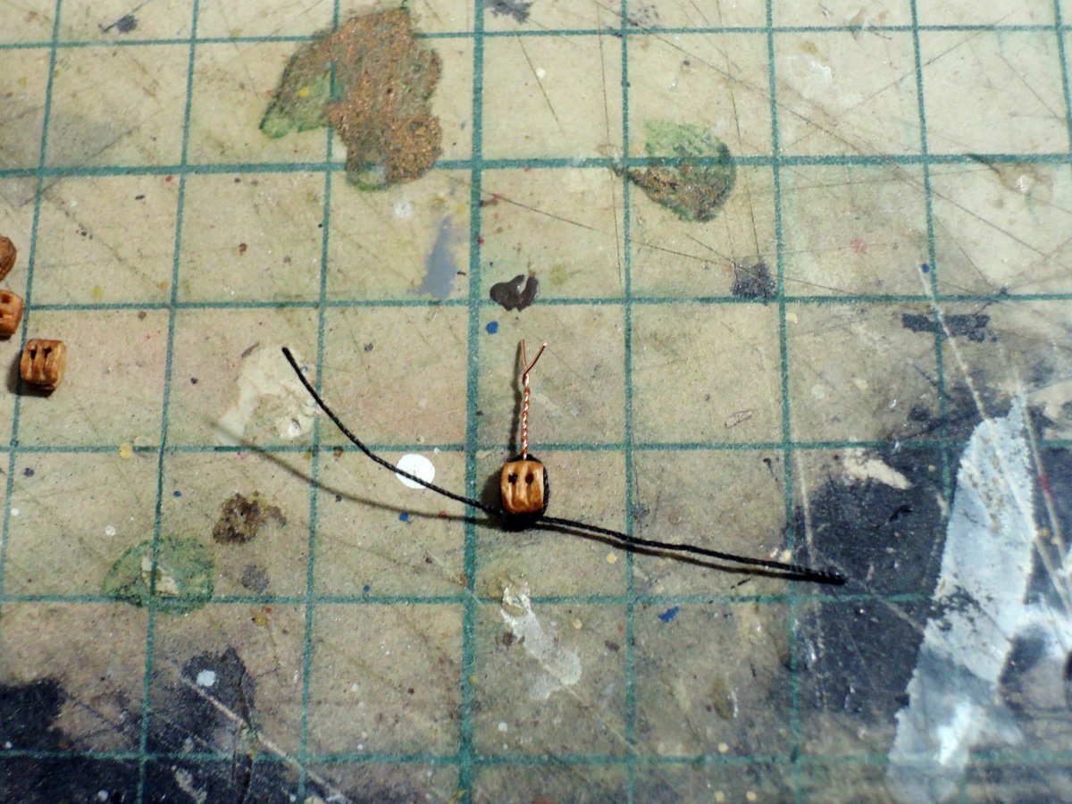
Hooks are added to gun tackle blocks. They are represented by turning copper wire around strop rope, then twisted and finally bend to hook shape.
Eyebolt positions of inner planks of hull are determined by help of template.
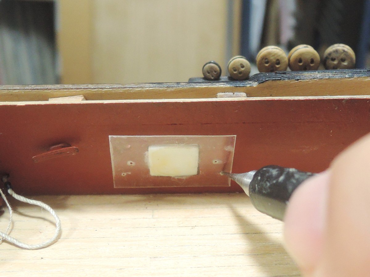
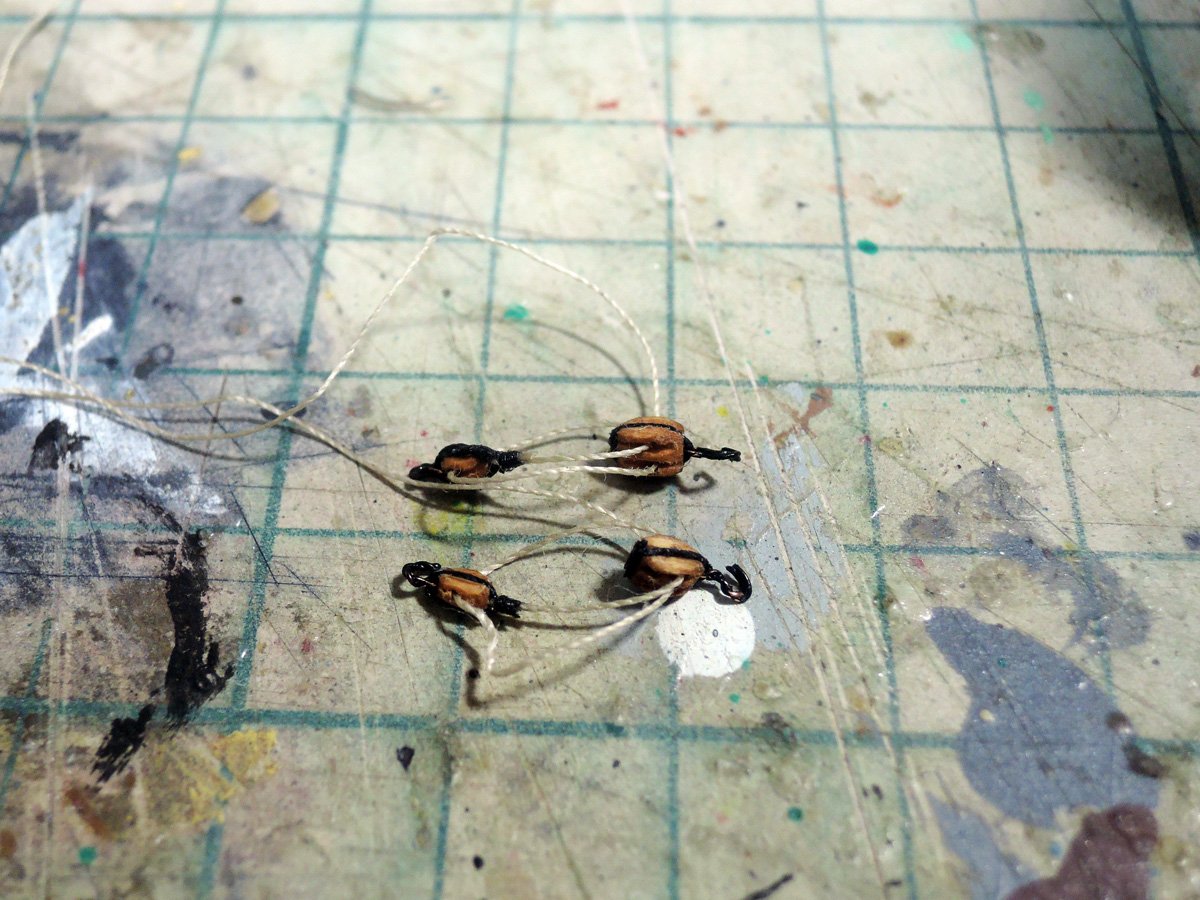
Gun tackles are fully rigged for guns of midship sections because they can be seen well from opening of waist.
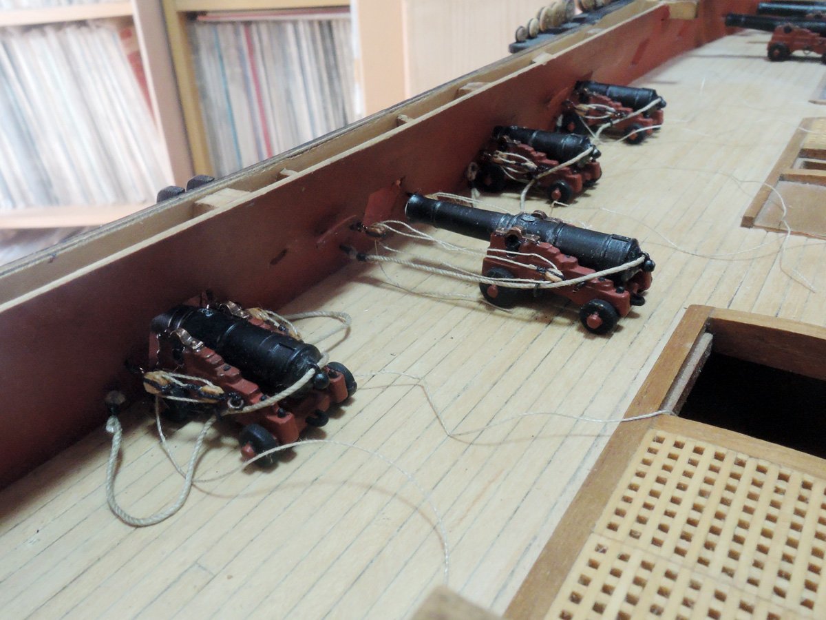
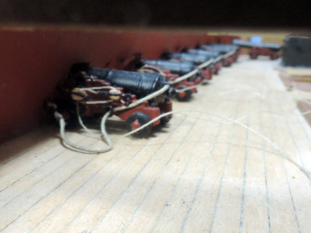
But those of each ends are simplified because they can't be seen well. Gun tackles are directly knotted and reeved between eyebolts of carriage and inner hull side, and finally small walnut pieces are CA glued to suggest blocks.
Gun tackle ends are separately coiled and glued to deck. They are omitted for aft section guns.
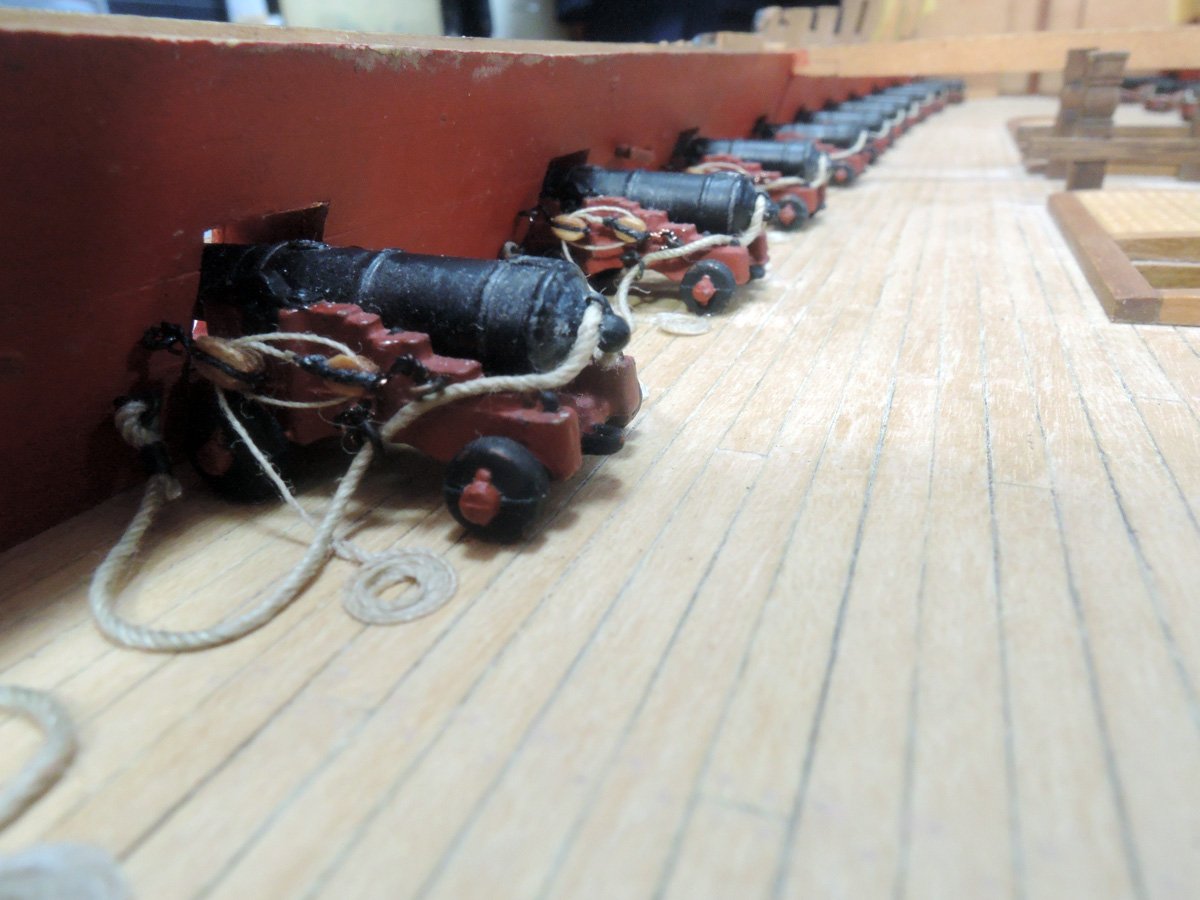
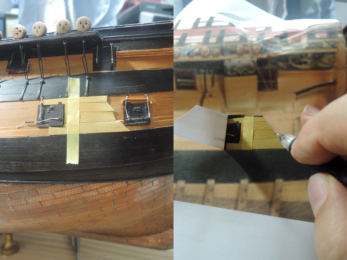
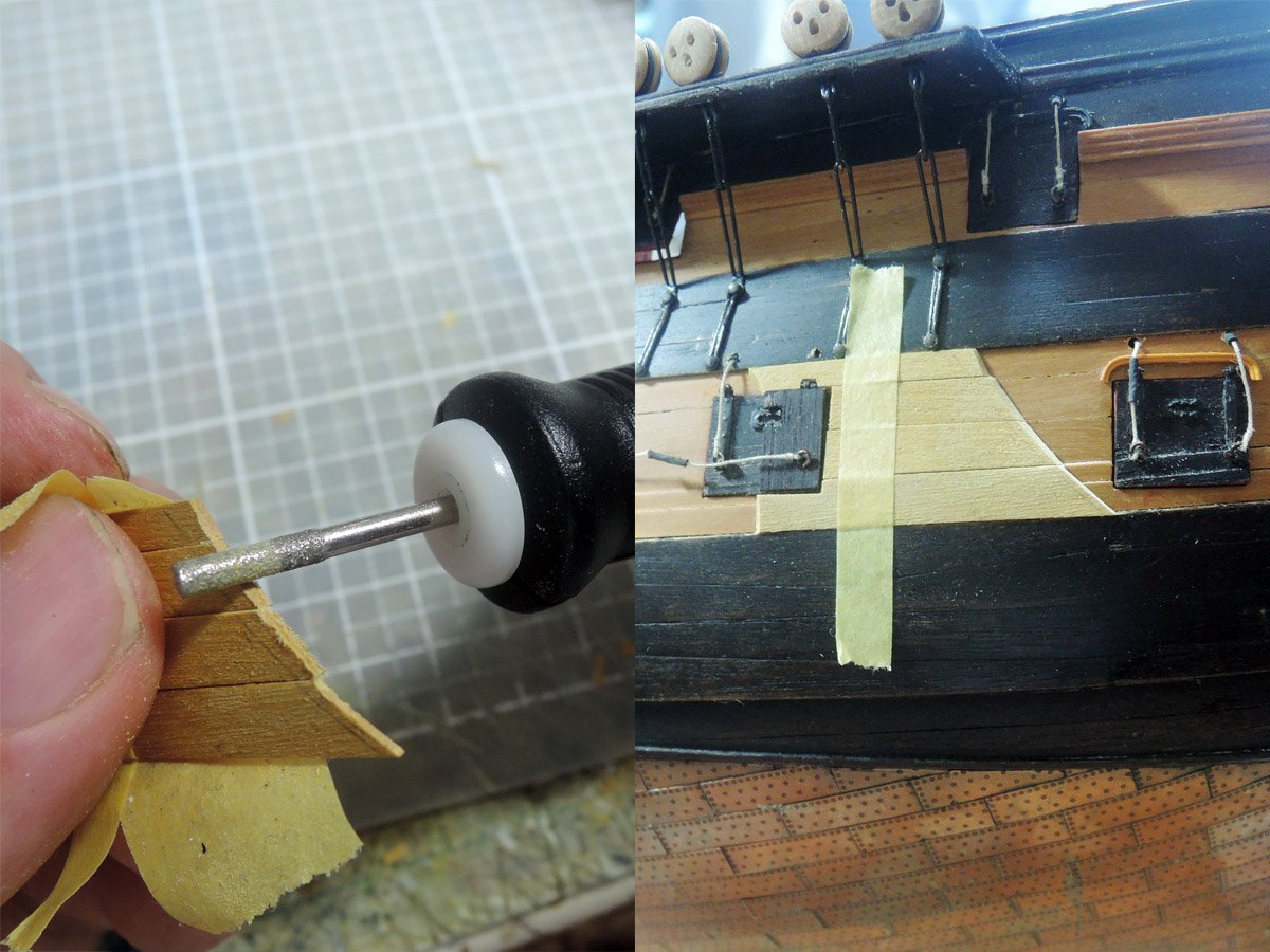
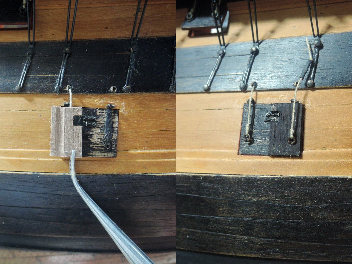
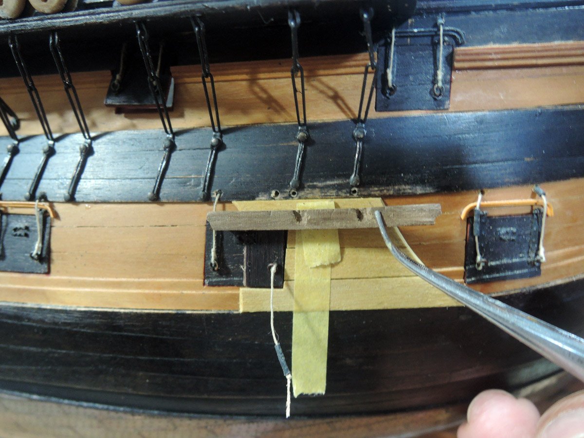
Along with 18 Pounders, cleats for main course tack and fore course sheet are also glued.
Sheave position of main course tack are altered according to suggestion of Alan.
-
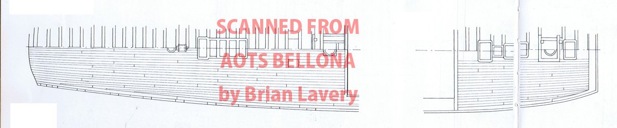
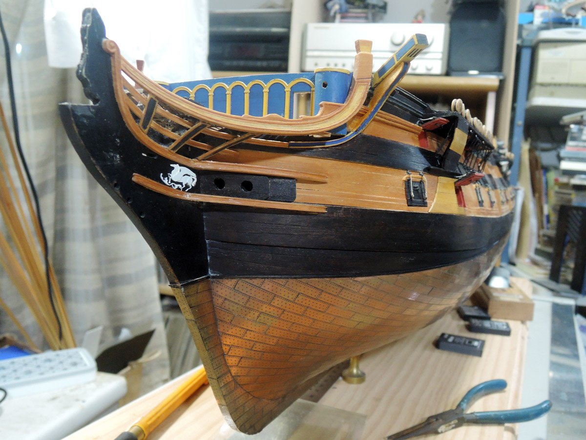
Anchor linings
Parts around anchor lining are ones of confusing terms in ship history. For example, Peter Goodwin depicts the part directly fitted to hull between main wale and chain wale as “anchor lining”, the part covering chain as “billboard”, and longitudinal part between them as “bolster”.
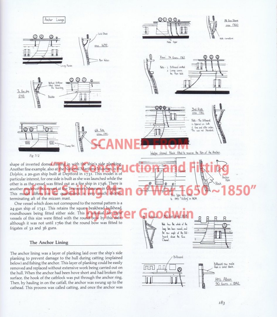
Other two images are I downloaded from the internet while ago, which I suppose scan from books of George F. Campbell and L. G. Carr Laughton. Former reverses usage of terms of Goodwin, and latter depicts whole parts as anchor linings.
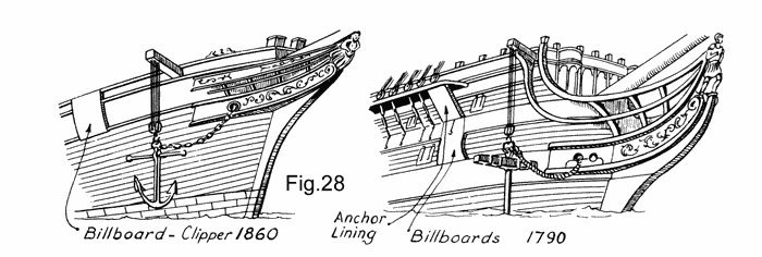
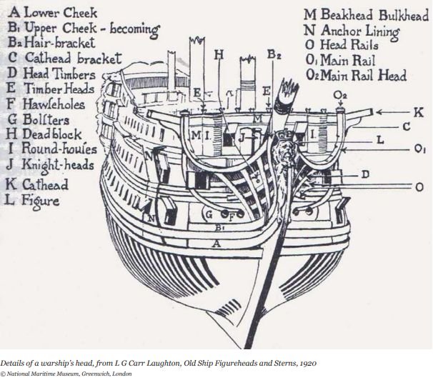
For convenience, I will follow usage of term by Goodwin.
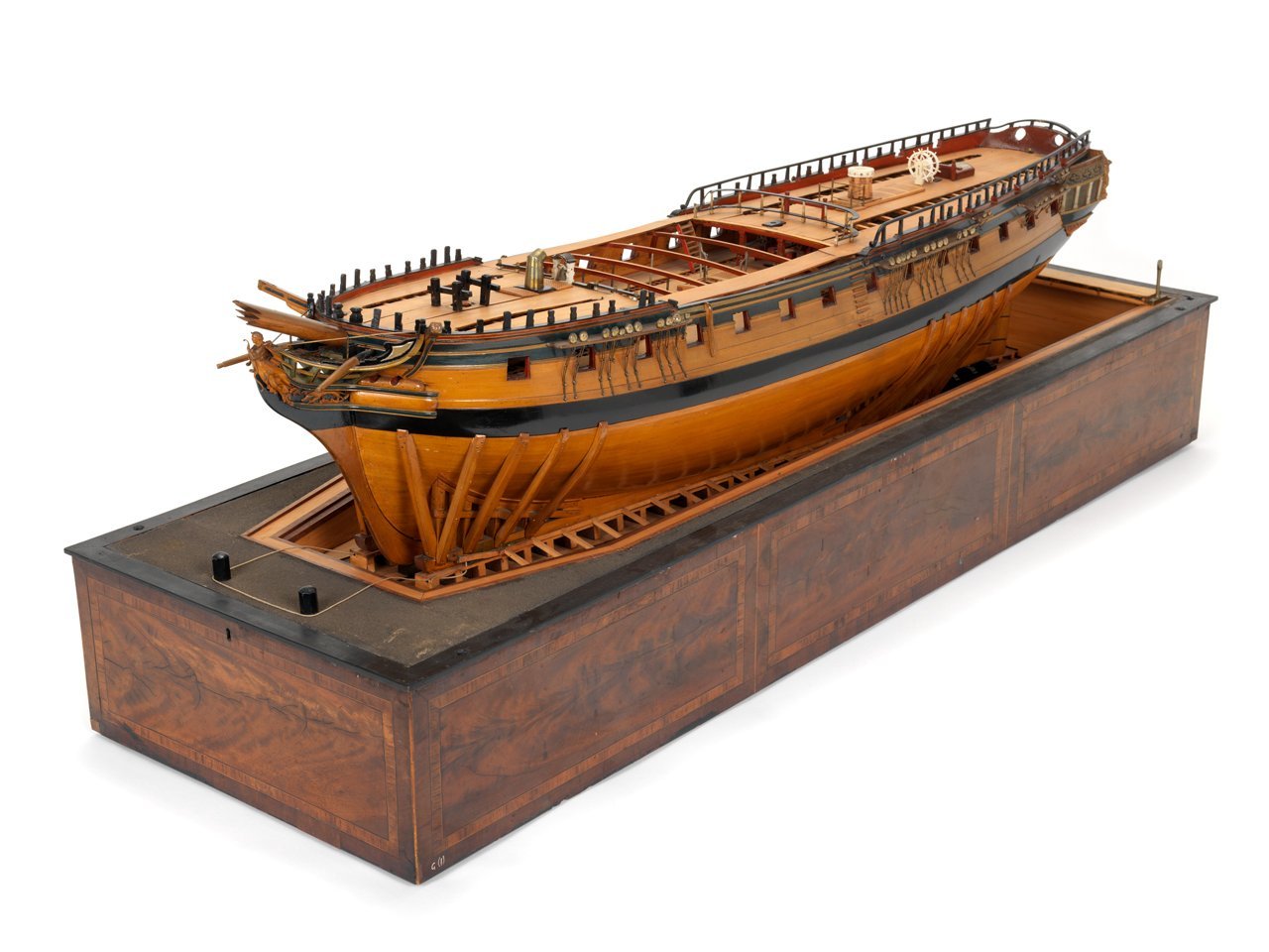
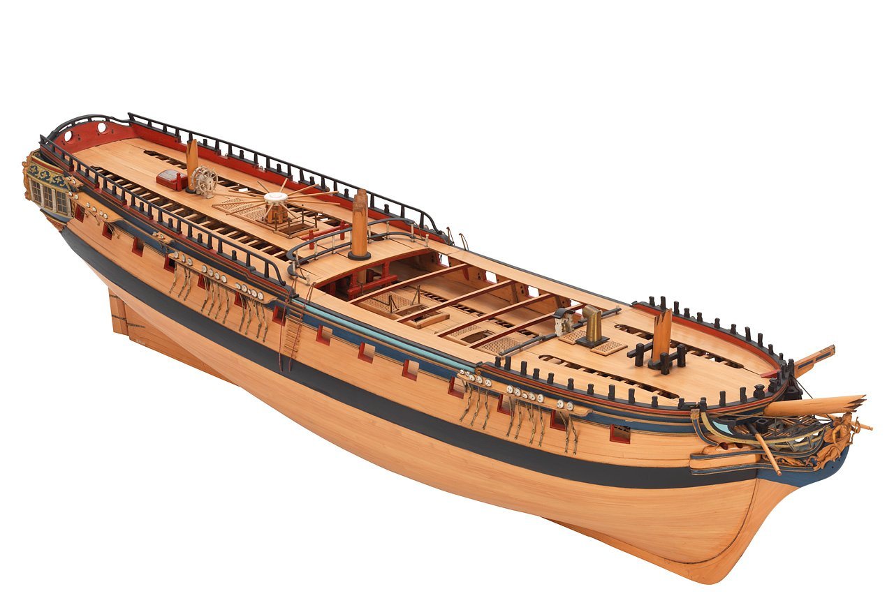
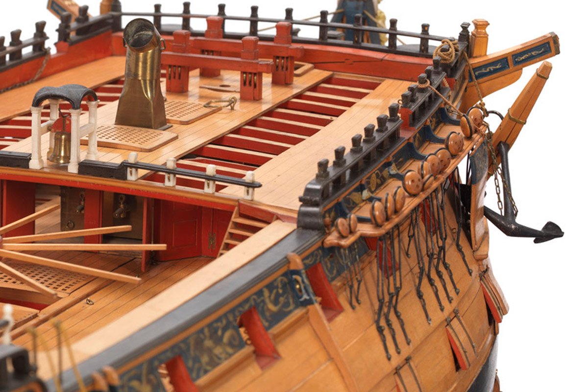
For determining their shapes, I referred Bellona coppered model.
https://collections.rmg.co.uk/collections/objects/66299.html
Firstly, side elevating image of Bellona model are enlarged to fit 1/72 scale. Outline of anchor linings are taken from it.
Anchor linings are made of amarillo strips. They are straight forward building of amarillo strips, but bottom lining strip should be thinned to fit diminishing depth of "thick staff" above main wale. Once shaping done, it was dry fitted.
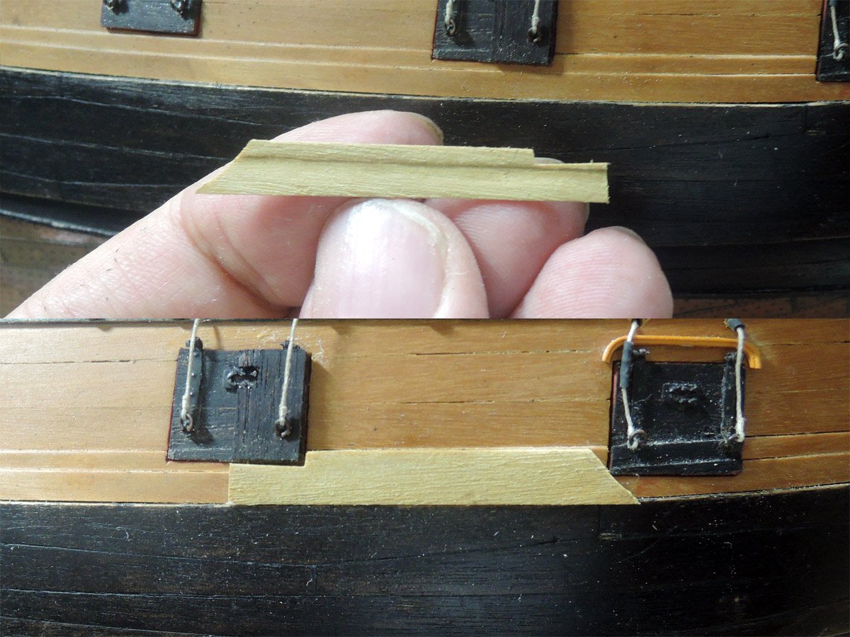
Rest of linings are roughly cut, dry fitted, determined outline referring enlarged Bellona side elevation image, and finally shaped.
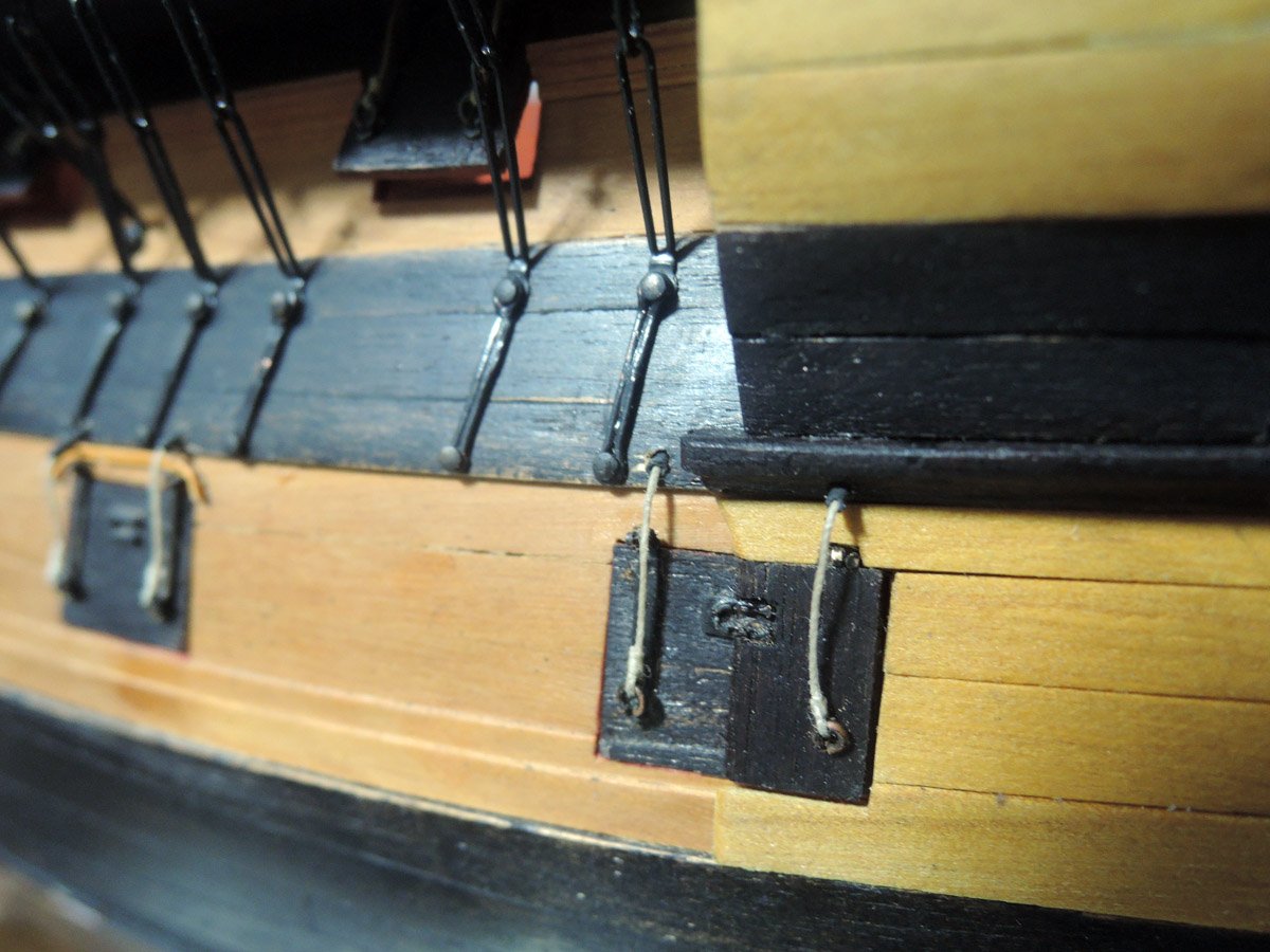
In the case of Bellona model, anchor linings are also covering forward area of second gunport of lower deck. It was made of 1 mm walnut strip, but it also should be thinned partly to clear gunport hinge.
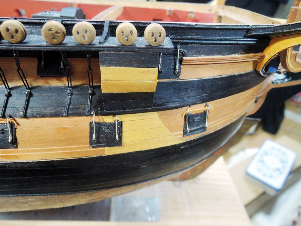
Bolsters are made of 3 mm walnut dowel. It also should be partly bored to clear preventer plates. Lengths of preventer plates are also shortened than other plates not to interfere with bolster.
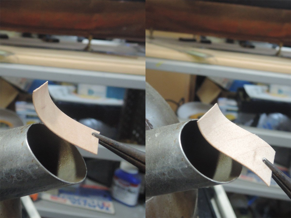
Billboard of Bellona model are showing gentle S shaped curve viewing from fore and aft.
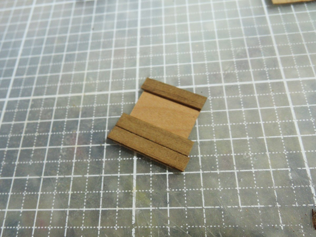
To represent it, I made billboard as lamination of 0.5mm maple sheet as baseboard and outer planks of amarillo and walnut. Firstly maple sheet is bent by steam and heat from kettle. Maple sheet can be bent to convex by applying steam and heat. S shaped curve can be formed by apply steam and heat to end of one side of the sheet, then reverse it and apply steam and heat to another end.
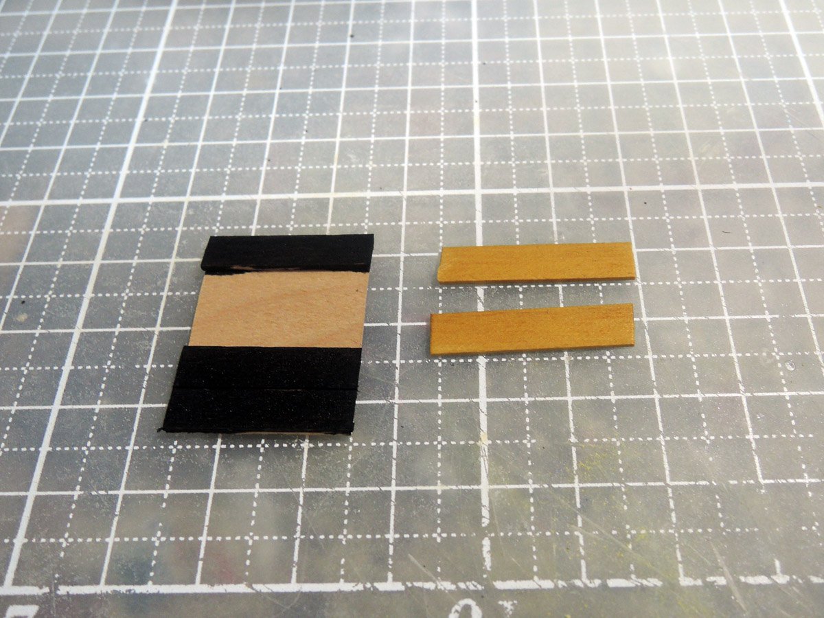
Outer planks are glued to be lined up with blackened wales and yellow plank between wales. Walnut strips are firstly glued then blackened by black dye and ebony colour Watco oil. Next glued amarillo strips.
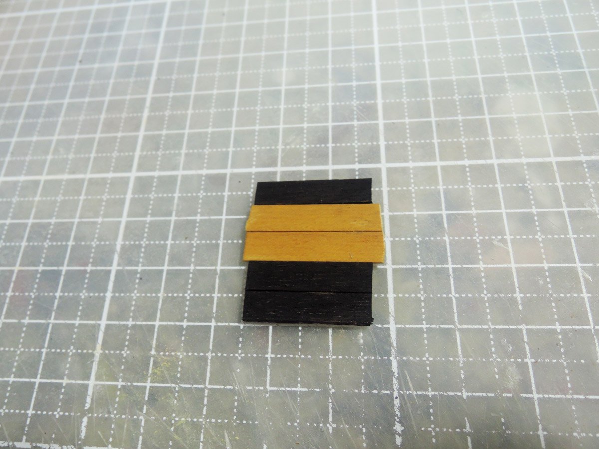
One of problem of Bellona model is that upper edge and bottom edge of starboard billboard seems to be parallel...
but those of port one seems to be twisted to fit narrowing line toward bow of each level.
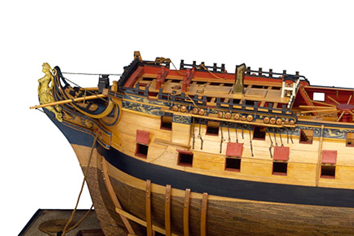
Image posted by Siggi52 are showing this twisting clearly.
I don't know which is correct, but twisted one seems to be more natural. To represent it, I twisted billboard lamination by putting pressure on my fingertips, but cracks occurred to maple baseboard. I repaired them with CA glue, but hindsight tells me that outer planks of walnut and amarillo should be also twisted before gluing onto baseboard.
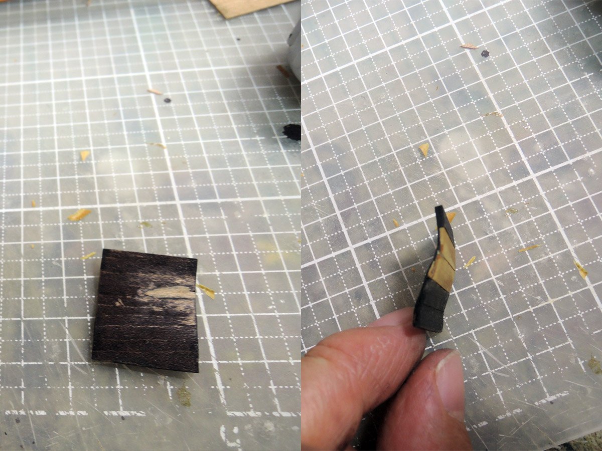
Anyhow, I made up my mind to satisfy billboard repaired with CA glue. Fortunately repaired surface can't be seen from outboard.
-
OC.
Thanks for your comment. While it is nature to seek accuracy as a modeller, different info sources are showing different interpretations of specific details. Changes of details are also matter of problem.
Considering of her building date, Bellerophon would have iron crutches on inboard edges of gangways as can be seen on model of Queen Charlotte of 1889 and skid beams would be rest on these crutches.
https://collections.rmg.co.uk/collections/objects/66516.html

But there may be also strong possibility her skid beams were changed into permanent structure beneath of gangway in her long active career as can be seen on sectional model of 74 gun ship around 1795.
Moreover, skid beams of today's Victory are showing some difference from sectional model of 74 gun ship. For example lack of hanging knees are one of them.
https://www.alamy.com/hms-victory-gun-deck-portsmouth-image212002530.html

After some thought, I decided to follow the way of 74 gun ship sectional model, but there still remains problem of what is right method of her skid beams construction.
Maybe answer is sleeping on contemporary refit documents if NMM is still preserving them. But it is slightly too maniac to seek such document for me as an amateur modeller. Anyhow I want to seek accuracy within limitation of amateur as far as I can do it😅
- mort stoll, bruce d, mtaylor and 1 other
-
4
-
Mark,
Thanks for your comment.
Today, I shaped balusters of ladder rails between quarter deck and upper deck referring AOTS Victory. Lower longer pair will be last parts to be installed onto upper deck.
After I install them, I want to start to write English text for updating this building log.

- Roger Pellett, bruce d, mtaylor and 2 others
-
5


_RMG_J2938.png)
Question on quarterdeck bulwark inside belaying points of English 74
in Masting, rigging and sails
Posted
Jaager, Gary and Mike,
Thank you for your useful discussion while I was sleeping and going to work. I re-recognized the risk of referring to surviving preserved ship.
Gary,
Thank you for detailed explanation of processes of restoring Victory to Trafalgar appearance.
I’ve recognized Wyllie only as painter of Victory under restoration and Laughton only as author of “Old Ships Figureheads and Sterns”.
It is great pressure for me to learn theses facts I didn’t know.
Thanks again all members on discussion.
Kindest regards,
Mitsuaki