


Hubac's Historian
-
Posts
2,939 -
Joined
-
Last visited
Content Type
Profiles
Forums
Gallery
Events
Posts posted by Hubac's Historian
-
-
Nice, clean work Eric. Will you go back to New London a week from Saturday?
-
As always, Druxey, you are very welcome. I appreciate your sticking around through this slow, steady climb.
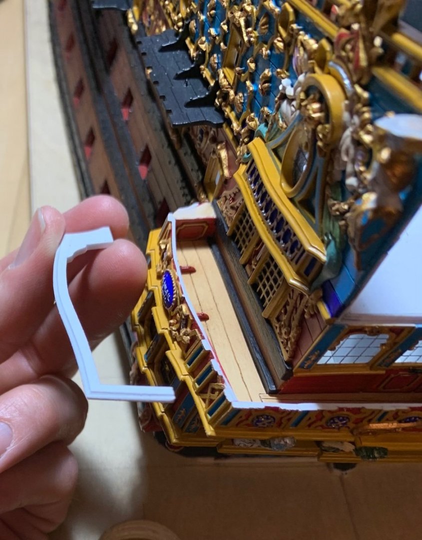
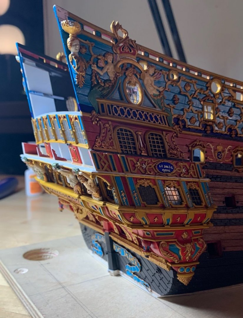
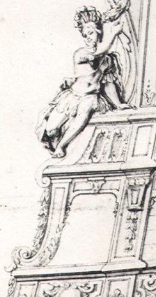
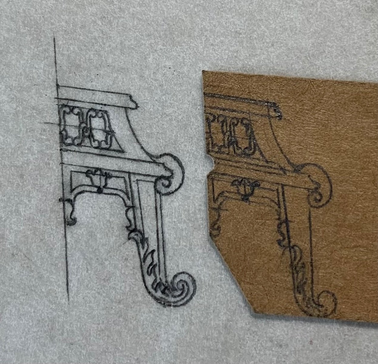
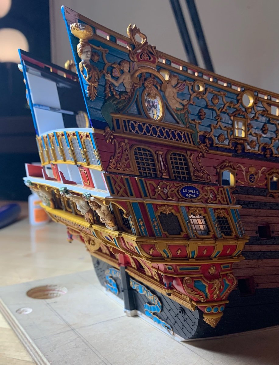
It has been suggested to me, by a friend on the other forum, that my pass-through arches might benefit from a slight re-design. His point was that the pedestal support, as it rises from the balcony rail, appears to move slightly away from the ship side:

I related that part of the reason for this is that I needed a wide-enough seat to accommodate the figures of Africa and the Americas, so that they wouldn’t seem cramped beneath the quarter-piece supports for the side lanterns.
When I reduced the sheer by 1/4”, I lowered these quarter-pieces, as well, so that they would be in-line with the sheer railing, as opposed to above the sheer railing. I even carved away the lower finishing of the quarter pieces and reduced their depth, somewhat, but they still present a challenge to spacing.
Nonetheless, the more I studied the problem, I could appreciate that he was right, and I found a path to get ever so marginally closer to what he was suggesting.
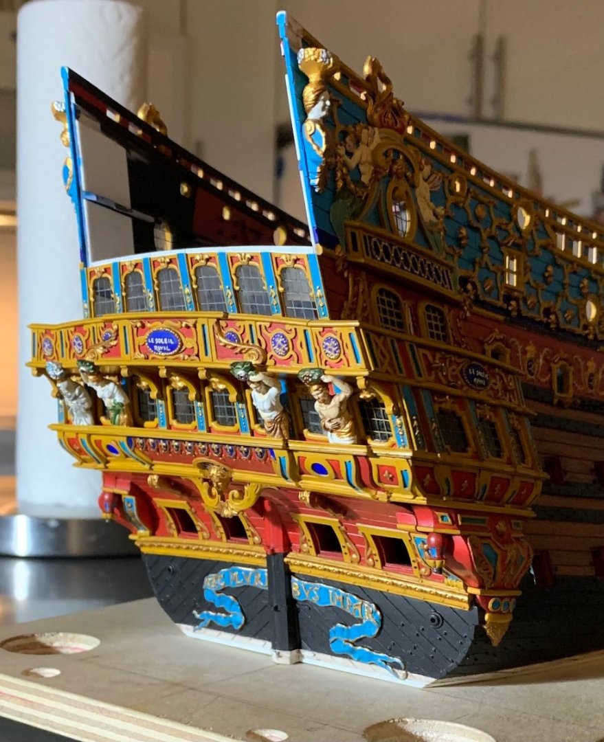
Now, the differences are slight. I kept the canopy at the same projection as before, but I redrew the support pillar at a slightly steeper angle toward the ship’s side, while increasing its heft. I re-drew all of the scrolls and the acanthus brackets and they are better now.
Here is the difference:

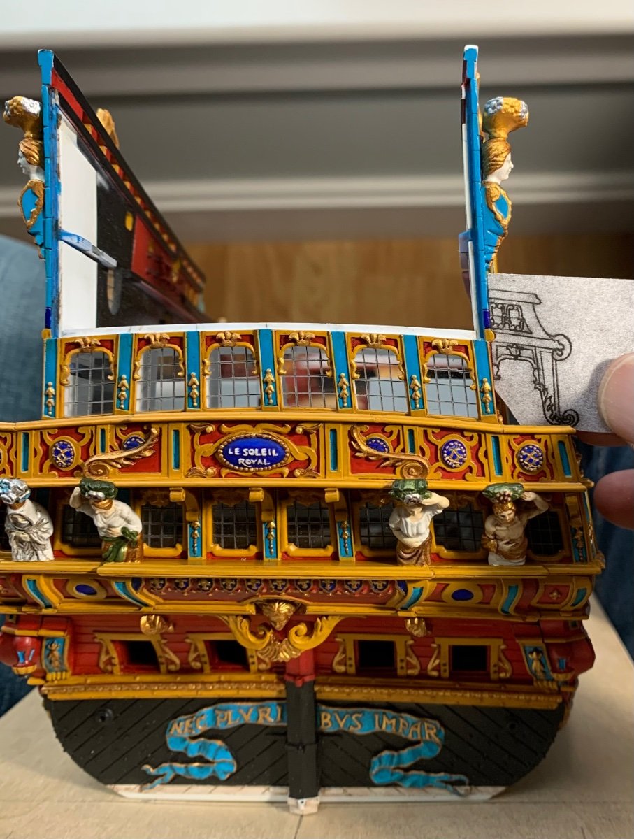
I will minor-tweak some of these panel reveals, as I make the parts, but this is what the new bracket design looks like against the ship:
This is not a dramatic difference, but it is a worthwhile improvement, IMO.
-
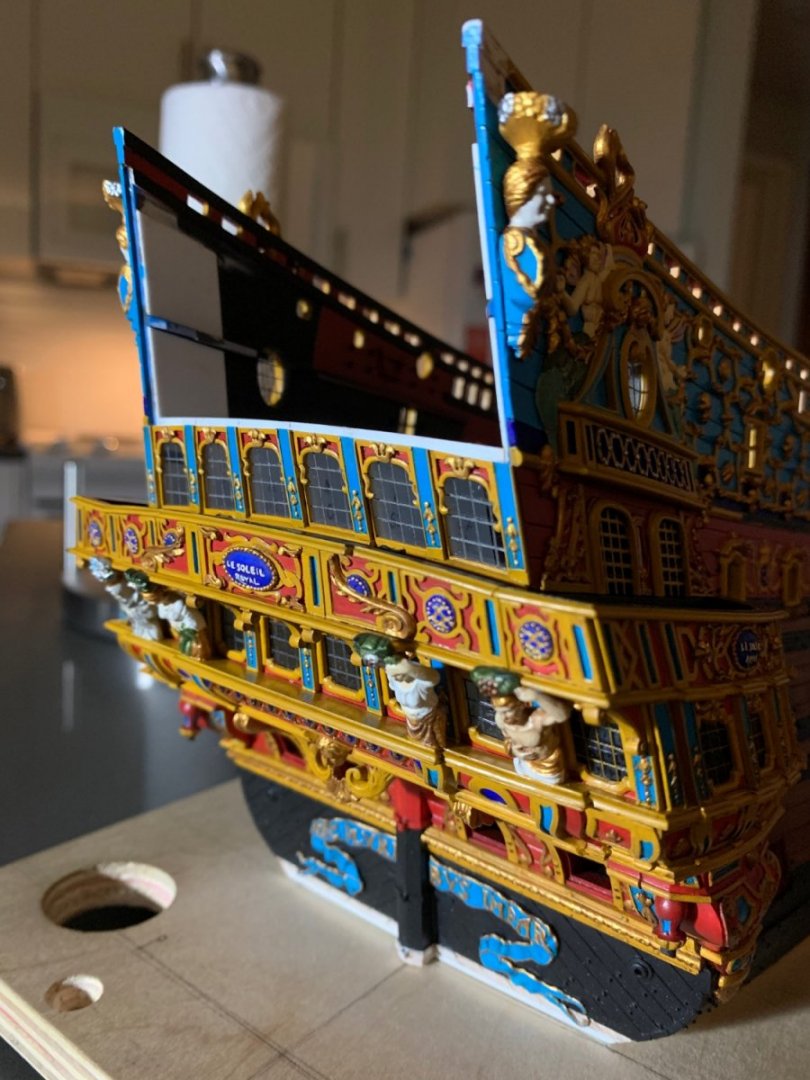
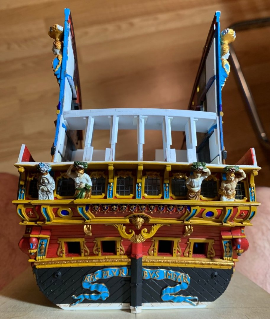
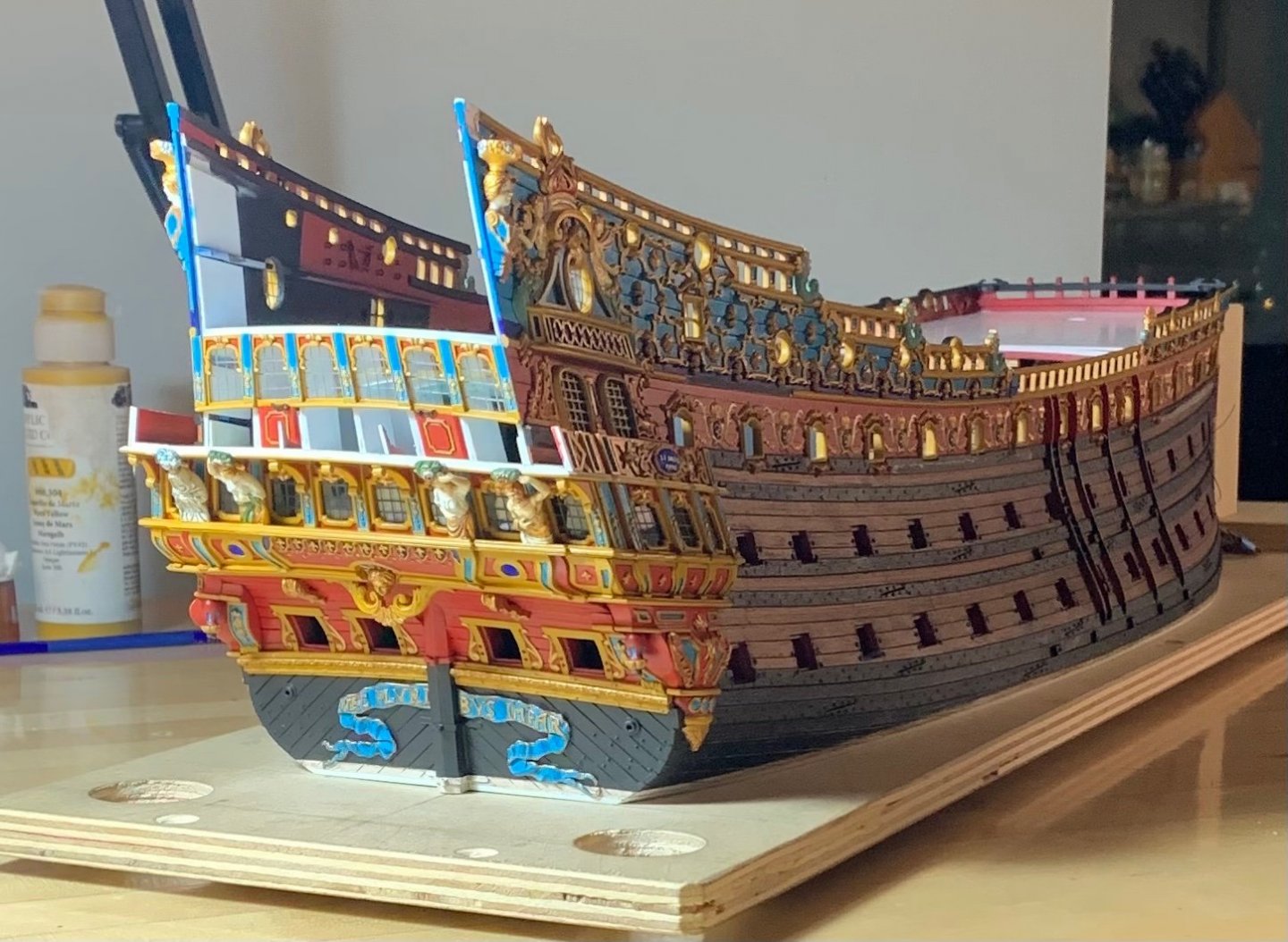
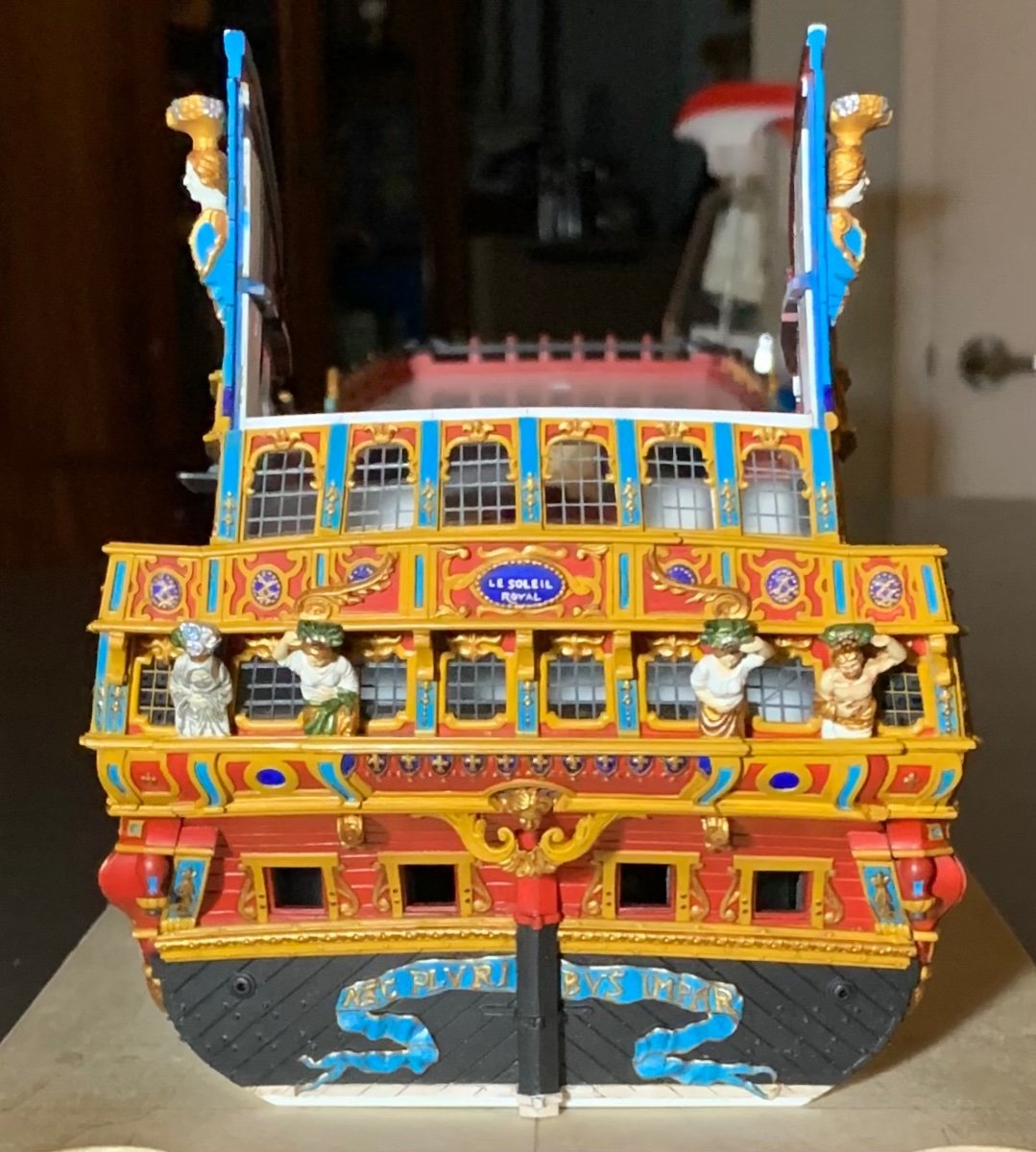
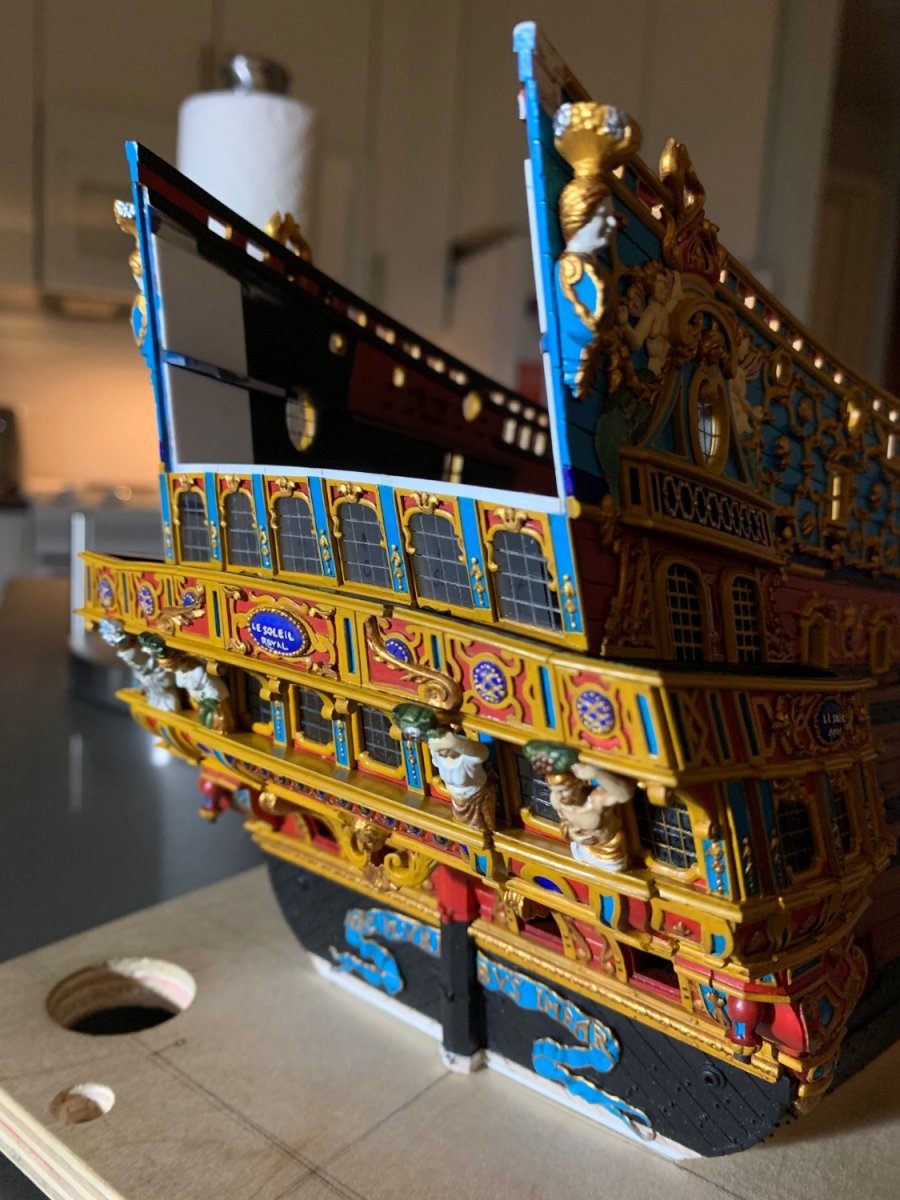
Yesterday was a milestone day as I completed the main deck gallery of stern windows and finally completed the wrapping balcony.
Per usual, there was quite a lot of touch-up, but here is where we are after applying the walnut ink wash:
Somewhat remarkably, I managed to avoid breaking the aft bulwark supporting knees, the angle of which had to be faired a little to match the corresponding rake of the corner joint.
Because the nature of this reverse-engineering project precludes a comprehensive drawing, from the outset, the build is always evolving, in-process. I realized, for example, that increasing the camber on this main-deck tier of windows ultimately necessitated adjusting the camber of the bulwark railing, if those two things were ever to agree with each other. Even though I thought I had set the camber of the windows to match that of the bulwark, it didn’t quite pan out that way, in actuality. Unfortunately, this only became manifestly evident to me AFTER I glued the bulwark in place. For the sake of comparison, here is the relatively flatter camber of the bulwark, prior to alteration:
Fortunately, there was enough solid-bond glue surface to enable me to re-shape the bulwark, in place.
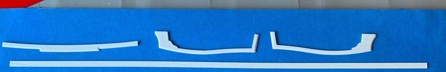
The bulwark cap-rail, itself, was determined by making graphite rubbings along the top edge with masking tape. This gave me the precise shape, as well as the location and depth of all of the pilasters, so that I could arrive at a reasonable overhang, without making the railing appear too heavy.
The forward end of the side cap-rails required some allusion to timbering, considering the need to cover the relatively large-scale expanse of the wooden end-piece beneath it.
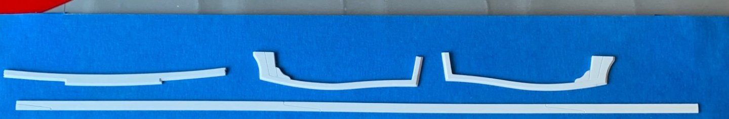
My big idea was to wrap the side railings over the corner join to the aft bulwark, thus re-enforcing the construction.
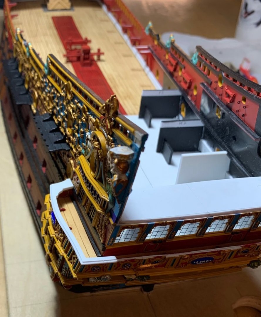
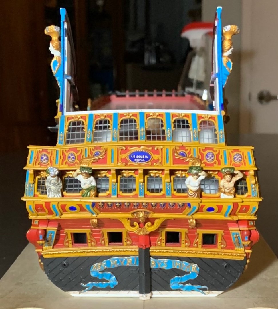
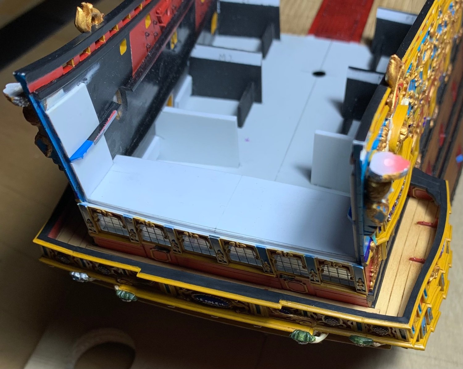
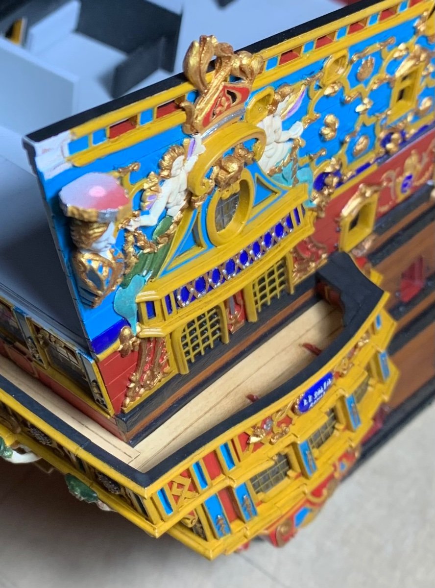
A few different perspective shots with all of the paint re-touched:


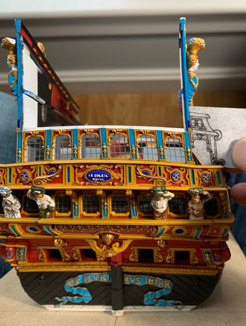
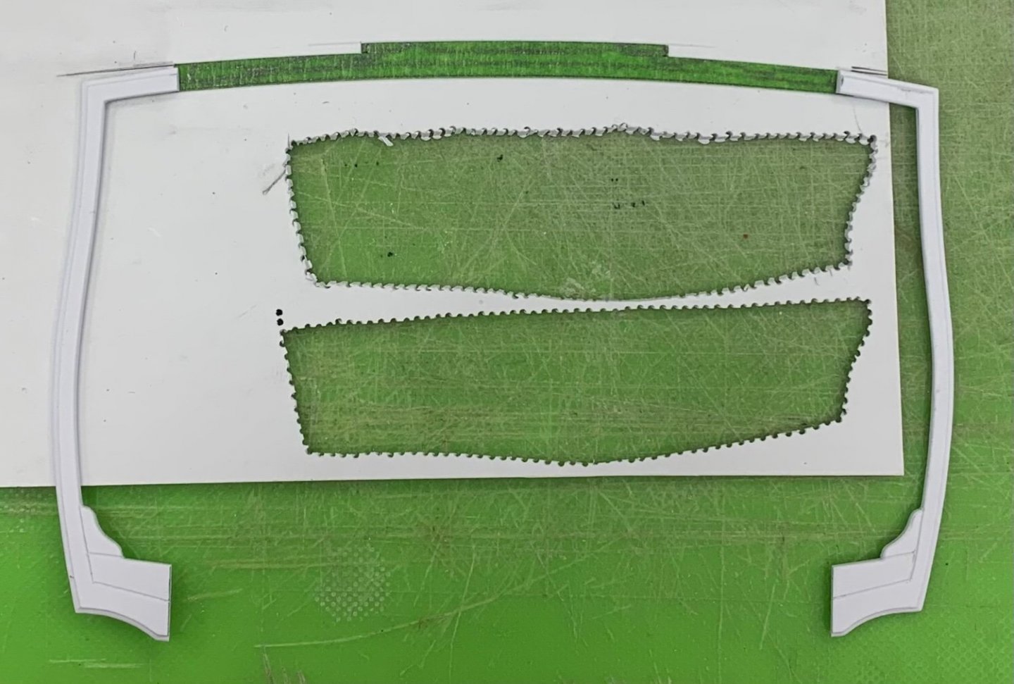
So, now the stage is set to make the pass-through archways that also serve as supports for the figures of Africa and the Americas. My adaptation of the Berain design is as close as I can keep it, while still respecting the particular slope of tumblehome on this model. Here, I’ve drawn my proposal directly to a cardboard pattern:

These will be fun to make, as I’ve made all other things like this, before; there will be a primary sandwich of three layers of styrene, with two thinner appliqués that make up the acanthus brackets, and applied mouldings that continue the lines of the upper stern balcony. There will be pierced fretwork and applied ornaments and all kinds of fun that add up to about a week of effort to make each bracket.
I’ve extracted two of the Four Winds carvings from the stock QGs, that will be fitted to the outboard surfaces of these brackets. I didn’t bother to draw them on the template, but here they are beside said template:
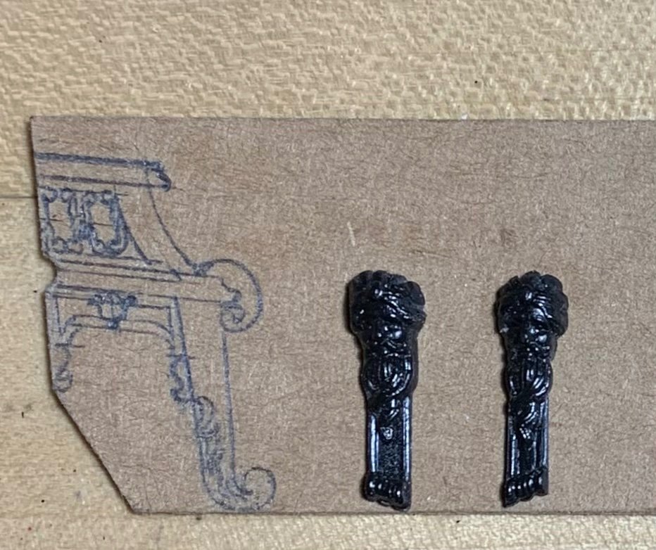
They will be reduced, accordingly, to fit between the upper and lower scrolled volutes.
As always, thank you for looking in, and for your kind comments and support of the project.
More to follow…
-
I agree with Druxey that this is an extraordinary effort!
- Keith Black, Siggi52, shipman and 3 others
-
 6
6
-
Super stuff, Kevin - it all looks as good as the real thing!
-
Gary - it is fascinating to watch your and Siggi’s build unfold; you are brothers from a different set of “mother” plans. I look on with the highest respect and admiration.
- scrubbyj427, mtaylor, Mark P and 1 other
-
4
-
On 4/2/2022 at 10:46 PM, Ian_Grant said:
Hello Twahl; you're on the same path I followed - a Heller Victory after 30 years away from models!
You're right, some of the wood blocks on the market are very square-ish and unrealistic. Have you looked at Syren's offerings? They make very nice blocks which I used on my Victory.
Having said that, they do add a fairly high cost to the build.
RJ's filing method will make the Heller blocks usable as far as stropping goes, but IMO the sheaves are molded far too small and the openings are too large. They are nicely shaped blocks though. When/if I get to my Soleil Royale I will weigh the time and trouble of modifying and painting Heller's blocks vs the cost of wood blocks.
Bear in mind that Heller's deadeyes are also unusable so there will be an after-market expense to replace them anyway!
Looking forward to another Victory build log! 🙂
Ian, as I consider your thoughts on modifying Heller’s SR blocks, I am already regretting throwing mine away. I am not un-familiar with them. The biggest issue was not having a stropping groove. Still, though - really good scale blocks are expensive.
-
-
I appreciate that you are taking the time to read through the log, again, Bill. The one thing that will not be possible to do as a full-hull model will be to increase the width of the hull, at the bow. That can only be done, if you cut away the lower hull. Everything else, though, is eminently possible.
And Vic, you're right - that scribing technique is a quick and easy way to go about making windows.
-
-
Congratulations on your fine presentation Msr. Huc. Thank you for sharing!
- EJ_L, Keith Black, mtaylor and 1 other
-
4
-
This is a treat for the eyes, Marc! I really like the pictures from above, starboard stern quarter; they really give a strong impression of the arsenal that was Soleil Royal. Love it!
- Bill Morrison, FrankWouts, mtaylor and 2 others
-
5
-
-
-
-
Fabulous! The teak has that really nice sun-bleached effect.
- popeye the sailor and Cirdan
-
2
-
Thank you all very much, Gentleman! And, Bill, I appreciate the thought, there. Some day, Nek0’s Soleil Royal will far eclipse anything that’s happening here, and I personally can’t wait for that to happen! In my opinion, his model is the king of all current Soleil Royal builds, and there are a number of very good ones out there.
- Bill Morrison, mtaylor, EJ_L and 3 others
-
6
-
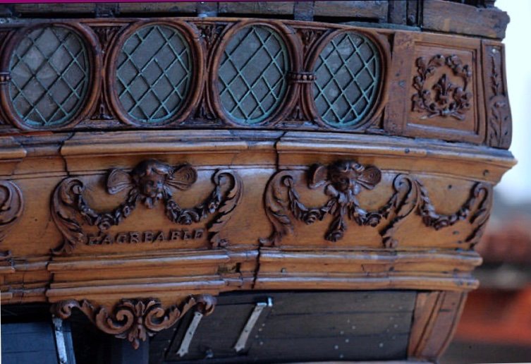
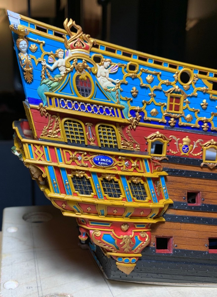
These window banks are incredibly labor-intensive, but the process of making them has been very enjoyable for me. What I am doing, here, essentially mirrors what Tanneron did for the sterns of his models. The damaged stern of L’Agreable illustrates how his windows are all pierced into one plate, as seen with the lower bank of windows:
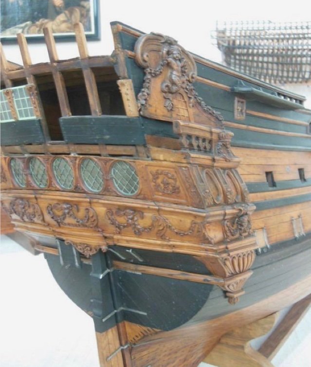
Considering the density of detail in such a small space, this method seems far easier than framing each individual window. Getting all of the elements (window frames and pilasters to flow harmoniously would, otherwise be quite difficult.
As I have done previously, I add window backstops to the bulkheads as added insurance that the windows can’t drop out of their frames, if the CA bonds should ever fail:
I remain indebted to Druxey for showing me how to make really good acetate windows by simply scribing the mullions into the acetate, and then filling those engravings with medium grey acrylic paint:
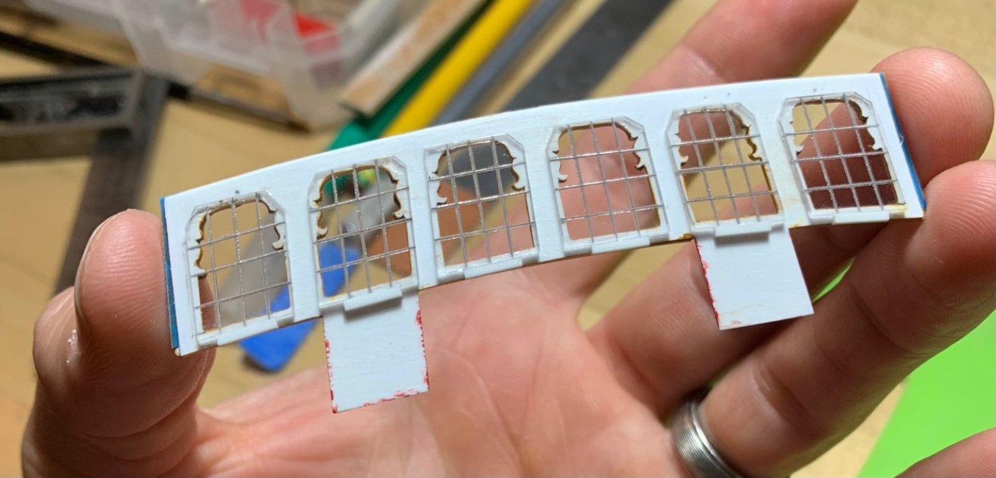
It really is simple and it just looks so much better than anything else, at scale.
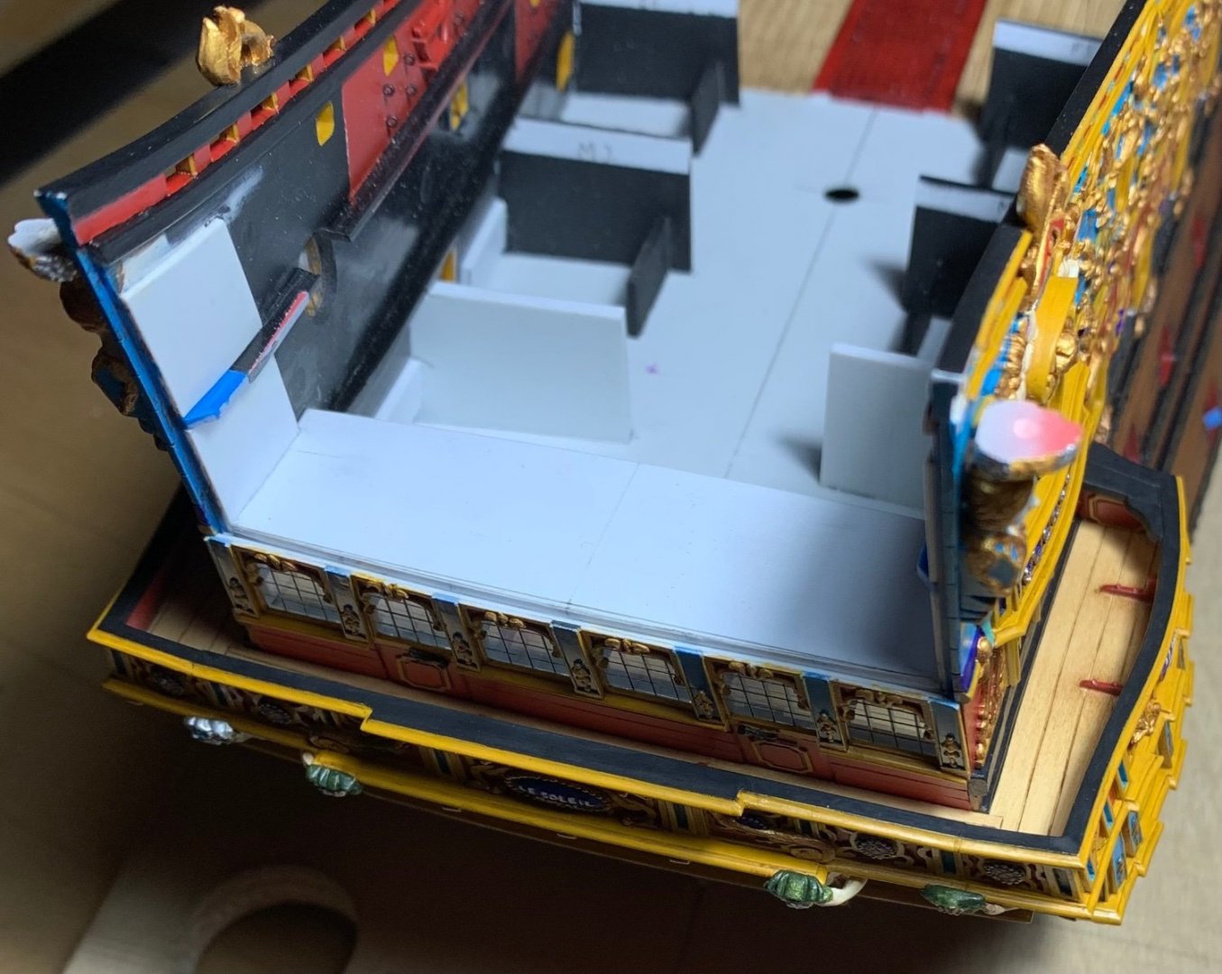
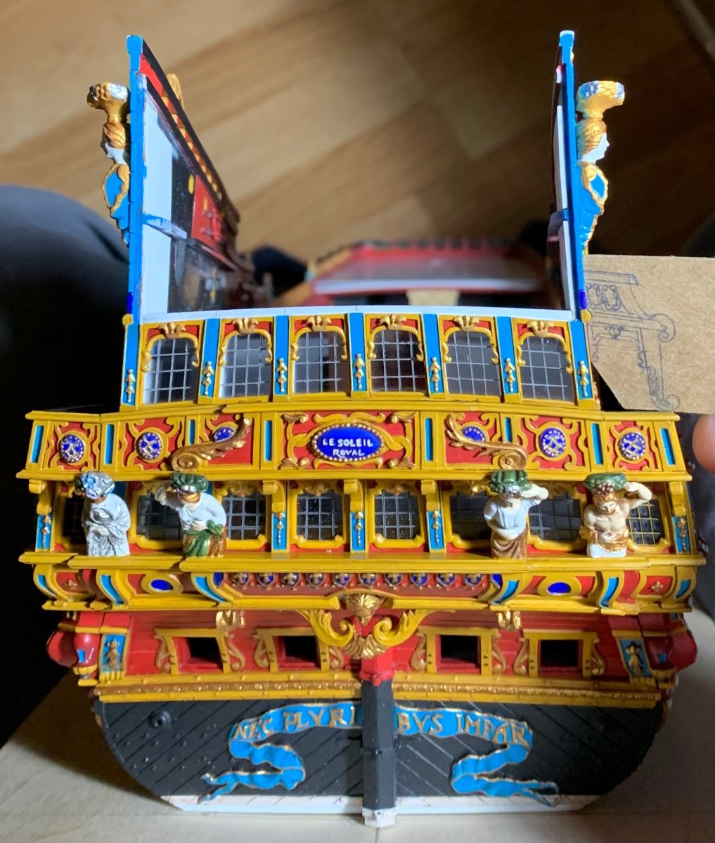
Of course, I will next plank-in beneath the windows, but I am pleased with how the stern is rising:
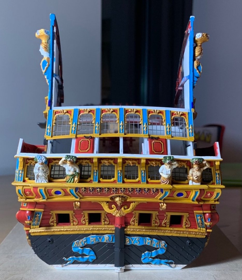
One detail that isn’t so apparent now, but will become so after planking, is the chamfer I filed into the door sides; this chamfer will create a shadow relief that will more clearly delineate the door opening. For the door handles, I recycled a pair of my frieze scrolls, which had the right shape and were sized closely enough.
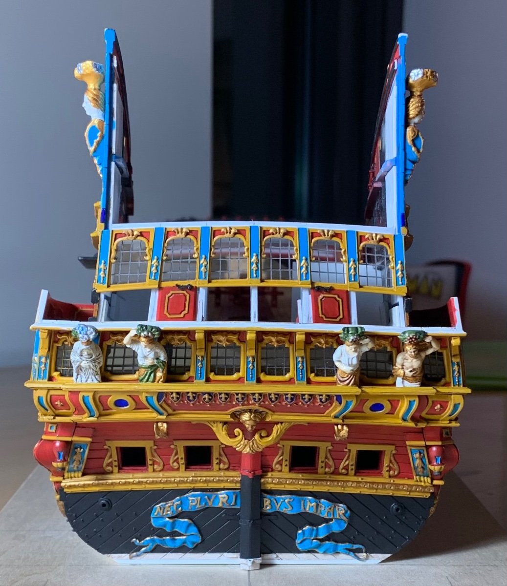
The round-up really helps to minimize the warped geometry of my stern:
At this stage, it is becoming more apparent how the increase in hull-width has established a more ship-like impression of a stable gun platform:
This is quite a difference from the stock kit.
So, I will plank and paint beneath the windows, install the balcony bulwark, and create the cap-rail for the balcony bulwarks. I will then take a break from the stern so that I can focus on finishing certain details.
I need to paint and install the starboard spirketting on the main deck. The f’ocsle beam needs re-touching, where I installed the moulding. The starboard bulwark joint needs to be puttied and painted. I need to fit, paint and install the quarter deck beam. Then, I need to retouch the exterior joint for the starboard aft bulwark. Finally, I need to install the starboard channels and fit all of the buttressing knees.
When all of that is ship-shape, I will return to the stern. One fun thing to make are the pass-through archways that support the figures of Africa and the Americas:
On the back-burner of my mind, I’ve been thinking about how best to make up this piece so that I can represent the delicate acanthus carvings. I think I know what to do now. The most important thing is getting the scale and shape of the opening right.
Following that, I’ll tackle the third level of stern lights.
Thank you for your interest, your likes and comments, and for looking in!
-
Your resolve is admirable, but I will tell you that I have watched many accomplished modelers who don’t come close to the fair run of your ceiling planking. Having never done it, myself, I can only guess at the difficulty of it.
- mtaylor, No Idea and michael mott
-
3
-
A better example of the shipwright’s art, there is not.
- druxey, Keith Black, mtaylor and 1 other
-
4
-
Super precise work, Ondras!
- chris watton, mtaylor, Ondras71 and 1 other
-
4
-
What the French have to offer, in the way of primary sources of 17th C. French practice is unique among European nations of the time.
First, there is the pictographically complete Album de Colbert, which illustrates the complete timbering and process of constructing an 80-gun, three-deck ship. As I understand it, there are a few small anachronisms between what the artist drew and what actual practice would have been in 1670, but the liner notes clarify these discrepancies.
Then, there is the Chevalier de Tourville, 1680, which is a distillation of Colbert’s son Seignelay, and Hubac’s son Etienne’s study of the English and Dutch construction practices, combined with Tourville’s conception of the ideal three-deck ship. The resulting plans are what Frolich used to create his model of L’Ambiteaux.
So, while complete sets of plans for actual ships in this period do not exist, it is possible to draft a credible reconstruction with accurate timbering, and in accordance with the known dimensions and armament of any given ship; this is the best educated guess that is possible.
- FrankWouts, mtaylor, EJ_L and 1 other
-
4
-
It is not even a contest, Gaetan.
- EJ_L, FrankWouts, mtaylor and 1 other
-
4
-
Also, would it be fair to say that the collection of Tanneron models were commissioned, in the first place, to be the visual expression of the more evolved and codified Second Marine of the 1690’s?
I don’t have good pictures of L’Agreable’s stern, so I can’t tell whether he modeled her with the pre or post 1673 stern:
Like SR, though, her 1697 refit drawing shows the early stern:
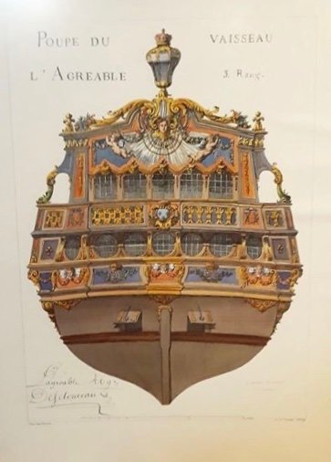
As you know - notwithstanding all of the problems you mentioned - I also agree with your basic premise that the Berain/Vary drawing must exist for a reason. From an evolutionary standpoint, this particular arrangement of the quarters is consistent with other examples that are better understood from the late 1680s/90s; lower gallery closed, middle gallery open and walkable, upper gallery a trompe l’oeil amortisement.
- mtaylor, FrankWouts, Theodosius and 6 others
-
9


Soleil Royal by Hubac's Historian - Heller - An Extensive Modification and Partial Scratch-Build
in - Kit build logs for subjects built from 1501 - 1750
Posted · Edited by Hubac's Historian
Thank you GP-Phil!
Partly, you are correct - it could angle slightly more inboard, but then it begins to affect my scroll spur (which supports the foot of Africa) in a way that I don’t like. Partly, though, it is the angle of the photo. This all looks a little better, in person.