


gsdpic
-
Posts
518 -
Joined
-
Last visited
Content Type
Profiles
Forums
Gallery
Events
Posts posted by gsdpic
-
-
I agree, I like the mirror too. Perhaps you already plan this, but any chance you can inset the mirror into the base instead of just having it sit on top? Maybe with the help of the fancy new laser engraver?
- mtaylor, mbp521 and Keith Black
-
 2
2
-
 1
1
-
-
7 hours ago, PvG Aussie said:
Gary, don't hold your breath waiting for the parts. They usually take at least a month to get to Australia! Sorry I sound like a sad loser. It is just that I know exactly what you're going through. If I were you, I would start to think of my next build.
Cheers,
Thanks Peter. A few months back, I ordered a few things that I could not find at any US-based store from spotmodel in Spain. Those took about 2 weeks to arrive, so that is my guess for these parts as well. But since it is just parts for the stand, I can finish the model and move on before they arrive.
-
Just a quick note that I already received a reply from Artesania Latina and they are sending the missing parts for the stand. So, happy with that level of service. I assume they are sending from Spain, be interesting to see when they get here.
- Canute, Jack12477, Old Collingwood and 5 others
-
8
-
-
Just a couple quick notes. I've not yet tossed this thing in the bin but the temptation has been going up of late 😬
I decided I wanted a glossier finish for my propeller, so moving in that direction and brushed on some microscale clear gloss. Was also wondering about/tempted to try some thinned down Tamiya "Clear Yellow" to warm up the color a bit more.
I started on the rigging with some of the rigging around the cockpit and it has been tricky. Not entirely pleased with the results but they are good enough, though in doing the rigging I also pulled loose one of the upper side metal cockpit parts.
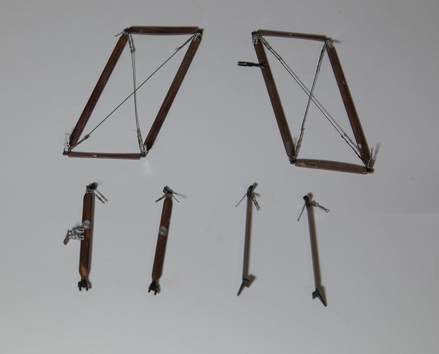
I decided to take a break from the rigging and assemble the acrylic stand, only to discover that three of the six pieces of the stand are missing. In the very first post of this log, with the unboxing photos, you can see the shrink wrapped stand with a large base and two curved upright pieces. There are supposed to be three additional smaller pieces that connect the two uprights. I went to the AL website and submitted a "parts request". We'll see how that goes. Looking at those photos, I also do not see the clear windscreen piece so I suspect it may have also been missing from the kit and not misplaced.
-
-
Thanks as always for the likes and comments. Ken, you may be right, though I thought this kit was fairly new. But I do not know its full history for certain. But I can say that I cannot imagine this kit without laser cut wood. Trying to hand cut all of the "lightening holes" in the ribs would drive me insane.
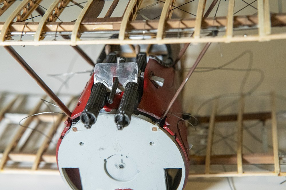
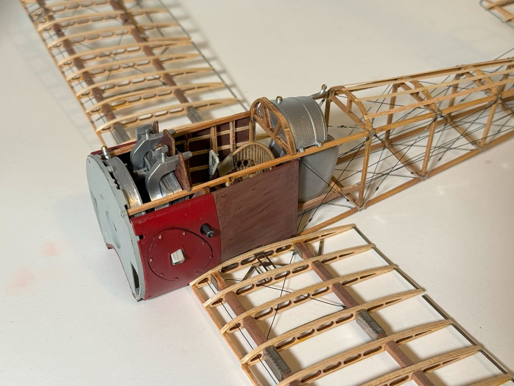
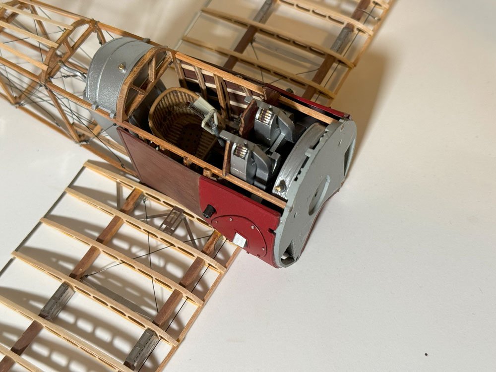
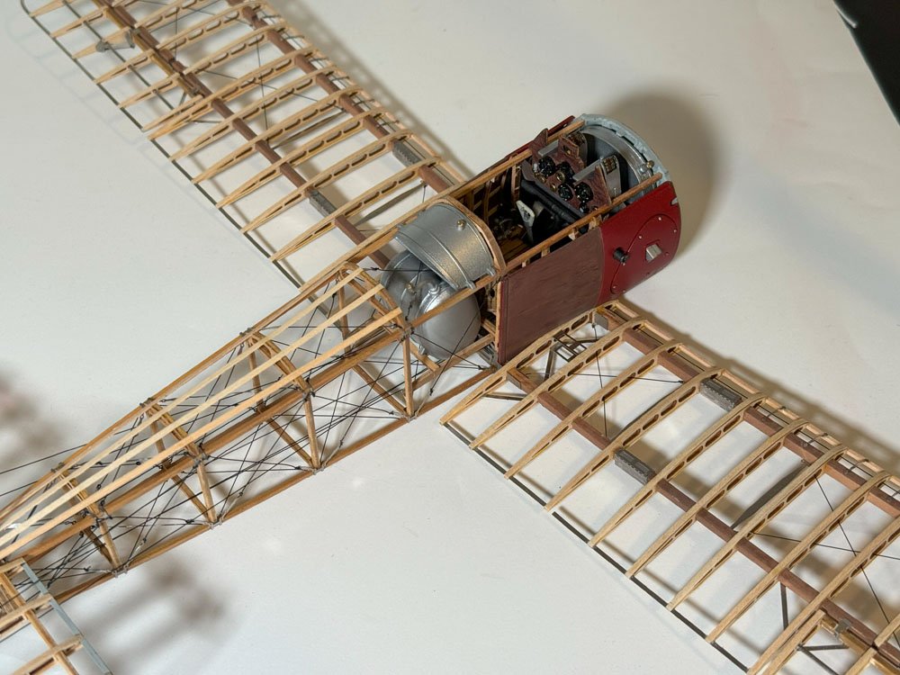
Anyway, with a bit of a struggle, I've attached the landing gear, the engine, and the front cowl. I already noted issues with the landing gear. The engine was mostly easy though I did have to snip off a couple "locator pins" on the back of the engine that did not have corresponding holes in the firewall. The cowl was definitely more of a struggle. The biggest issue was that it was a rather tight fit and it is tricky to figure out how to grasp the model firmly without breaking things.
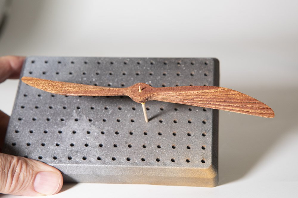
At this point, there are just a handful of small parts remaining, plus the propeller and the rigging. The prop is laminated from 6 or 7 laser cut pieces of a dark wood...mahogany or walnut or something...and then sanded to shape. I've started on that but have a way to go with it.
Oh, they also provide an acrylic stand that needs to be assembled and glued together if one wishes to use that.
-
Thanks for the likes and comments.
@PvG Aussie it is strange to me....though I admit I know nothing about manufacturing, I am a software guy....but the laser cut wood pieces for the most part fit together great. It has been the cast and photo etch metal pieces causing most of the problems. I would have expected the casting of metal to be more "precise" than laser cutting wood. Though in the description below I guess there was a counter example to that.
And yes, I am getting close to completion, definitely in the dangerous "just want to finish the project" mode.
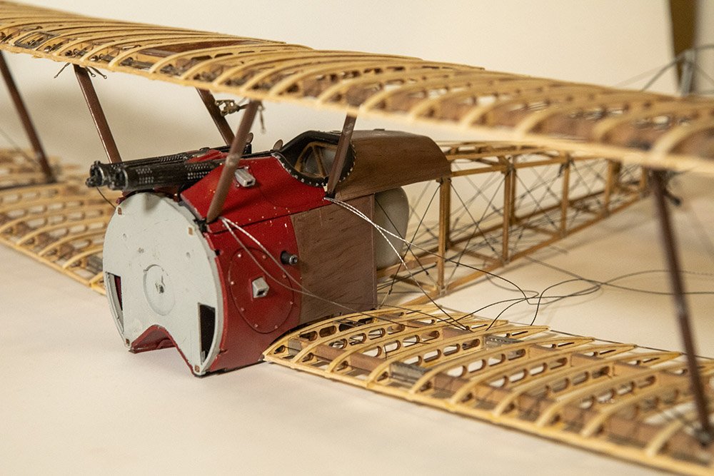
I got the windscreen and third small gun installed. The windscreen does not look as scratched/fogged as it does in the picture. All those bits were a challenge to get in place. A lot of that work would have been easier before installing the top wing, but you really had to put the top wing on first to locate the struts.
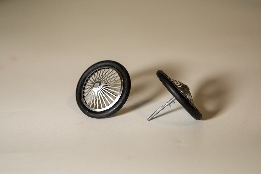
I've also started on the landing gear. Below is a picture of the two wheels. The tires were cast metal, painted flat black, while the spokes were photo etched parts, and the hubs and axles were also cast metal, all glued together with CA. The design of the wheels was such that they should be able to spin, but I guess I got a bit too much CA where it should not have been, so my wheels do not spin. The cone shaped outer spokes were a bit of a challenge to get them in place.
I've now started trying to put the landing gear struts on the fuselage, but that is proving to be a challenge. Each strut attaches to the frame in two places. In the front, some of the cowling and internal photo etch are getting in the way a bit. At the rear attachment point, it is not fitting due to a prior tweak I made. Way back in post #17, in the second and third pictures, you can see that I doubled up the frame across the bottom in the cockpit area, to compensate for the poor fit of the wood pieces at the side of the cockpit....the laser cut wood pieces were too short for my model. Anyway, the rear attach point of the landing gear is supposed to sort of clip on to that fuselage frame but it cannot because my frame is twice as thick right there. So I need to figure out if I can cut away a bit of that doubled up frame or if there is some other way to compensate.
-
As always, thanks for the likes and comments, and to those who just take a look from time to time.
The kit continues to be a bit of a roller coaster, as some parts go well and others are a bit frustrating. The most recent bits fall more into the latter camp. I've put on the rest of the metal parts around the cowl and cockpit. The fit of those parts ranged from mediocre to poor. The one "poor" fit was the piece between the two machine guns....I admit the instructions did call that part out and say "adjust if necessary" showing someone taking a file to the side of the part. Sadly, no amount of filing would make the part 1/8th of an inch longer, which probably would have helped. As for the other parts, they did not always line up well and it was difficult to tell where the back side of the part came in contact with the rest of the model....e.g. where to apply glue. Further, those parts had three different "access holes" to allow access to the filler caps for fuel or oil tanks. Two of those holes do not line up at all with the tank filler below and the third partially lined up. Oh well. Below are some pictures. Oh, you can also see some loose rigging...those lines had to be glued to the back of the metal parts before installing the metal parts. The other ends will be attached in later steps.
Next up is the windshield, though I seem to have misplaced the clear plastic bit for that. But it should be easy enough to recreate it from the ton of clear plastic packaging used to contain all the cast metal parts in the kit.
-
Looking good. I like the way the icebergs in front fit together.
Do you plan to add any tinges of color to the icebergs? Maybe a tiny bit of brown/tan and some blue or blue/green?
- Canute, Glen McGuire, Scottish Guy and 2 others
-
4
-
1
-
The sails, like the rest of the model, are really looking great! For some reason, I feel like sails really belong on a model with fore-and-aft rigged sails. They really add to the model without obscuring the view of the rest of the model as much as square sails.
- GGibson, Glen McGuire and John Ruy
-
2
-
1
-
Thanks for the likes and for following along.
I got the upper wing attached. It went much smoother than I expected. As I have sometimes complained about this kit, it is only fair that I now praise it for how this step went. The fit of the struts and the assembled wing was excellent, posing no issues at all. I first glued the outer struts to the lower wing, making sure they were vertical. Once that set, I merely placed the upper wing in position and it fit with virtually no fiddling around. Once that set, I added the four struts between the edge of the cockpit and the upper wing. For all of these steps, I've been using two part 5 minute epoxy glue for its extra strength and since the bonds are between wood and metal.
I hesitate to jinx myself and say this, but I am really quite close to the finish line. I've already assembled the machine guns and engine, they are next to go on, along with a few more fuselage panels around the cockpit. The only possibly tricky bits remaining are the landing gear and of course the rest of the rigging of the wings. Oh, I also want to redo the rigging I did on the rear stabilizer as it is quite slack and I think I can get it more taut on a second try.
-
Thanks everyone for clicking the ol' like button.
I've now completed the struts that go between the wings, as shown below. The two outer struts with the crossing tension wires were done differently. The one on the left was done some time ago using the beading wire and little metal crimp tubes, with some CA as back up to hold the wires. The one on the right was done with the stainless steel wire I mentioned above, twisting it around itself and bonding with CA. I will likely stick with that method, though the one on the left is good enough, and similar enough, that I don't plan to redo it.
You can also see here the photoetch turnbuckle assemblies at the corners/ends of the struts. Those were a bit tricky to make sure you bent them the correct direction for the particular location. And as mentioned, gluing them on was tricky as well. I ended up filing off the paint where those were to be glued on and that helped. The pieces also have two holes that I guess could be used to help secure them with some thread or wire, though that is not explicitly called out in the instructions. I think that would also be very tricky to do, though I might attempt it before moving on.
The next step is to glue the two outer struts to the lower wing, then place the upper wing on them, then add in the inner struts between the fuselage and the upper wing.
-
35 minutes ago, Keith Black said:
Great story, Bob.
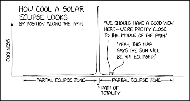
Glen, great photos but I think the eclipse was way over hyped. Maggie and I sat on the front steps with our I can't see a bloody thing glasses and observed 98.11% totality in our area. I'm much more impressed by comets.
Comets are cool, but the difference between 98.11% totality and 100% totality is like the difference between night and day....almost literally.
From XKCD:
- GrandpaPhil, Keith Black, Canute and 2 others
-
5
-
Nice! I too was scheduled for about 3 minutes of totality but looking at the clouds and weather forecast apps, I hit the road and drove up to just north of Llano. I got there about 25 minutes before totality and it was still cloudy. But soon a hole in the low clouds opened up leaving just some high, thin clouds, and I took some pictures of the partial eclipse. Then just a couple minutes before totality the clouds rolled back in. But fortunately, the atmospheric temperature changes at totality caused those clouds to dissipate so I had a clear-ish view for all of totality (the high thin clouds remained but did not interfere too much).
I see there is an "eclipse madness" thread in Shore Leave. I'll post a few pictures there so as to not hijack your thread any more.
-
I wonder about first sticking at least some of the pieces together with plain white glue until you get things aligned, so that it is easier to undo. Then once it is together use regular plastic cement. Though that might be hard to do without messing up the paint so may require touch up.
-
12 hours ago, CDW said:
I'm having a difficult time with the turbocharger assemblies. There are many parts to each side of the assemblies and the challenging part is finding a correct way to assemble so as all line up properly in the end.
At this point, I need to disassemble what I've done and start over again, without destroying critical parts in the process. I'll even need to disassemble the headers as well as the covers that sit atop the injectors.
The areas I highlighted in yellow on pages 3, 4, and 6, give an idea of the complexity of the turbocharger pieces and how they must align.
122969-21-instructions highlighted turbo chargers.pdf 12.58 MB · 3 downloads
That's unfortunate, but thanks for the heads up. I actually bought my own copy of this kit off of ebay a few weeks back. Not sure when I'll start on it, I've got way too many things in my stash and really want to wrap up the Sopwith Camel before doing another car. But yes, that engine looks pretty tricky. What you've done so far looks excellent; hope you can recover with out too much grief.
-
Ok, finally some updated pictures of where I am today. I've glued the two outer lower wing sections on as well as the two sides of the front cowl and cockpit. The latter were cast metal pieces, which I painted much earlier.
Gluing the lower wing sections was just a bit of an adventure. There was a sort of scarf joint in the spars that you glued together and then there was a photo etch piece that was bent into a U shape and placed over the scarf joint for extra strength. And while doing that, the plane could sit in a provided jig that had three vertical supports for each wing to get the dihedral correct. But there were two problems. First, the innermost vertical jig support was at the same location as the joint between the inner wing and outer section, so it was a bit in the way. Second, the photo etch piece was too big, as the wing spar was about 1/8th inch square stock but the photo etch piece was more like 3/16ths from top to bottom. Having it too large top to bottom made the first issue more problematic. I just left the photo etch piece too big, and removed the first support from the jig when gluing the wing.
With this, I am through step 30 out of about 47 steps in the manual, though in the past I have skipped ahead and done several of the remaining steps, such as build the engine, assemble the machine guns, etc. Next up, I will be finishing the detailing of the struts between the wings and then putting the top wing on. I suspect that will be a tricky operation.
- Ian B, GrandpaPhil, Canute and 14 others
-
17
-
7 hours ago, CDW said:
I love the scale look of your Camel, Gary.
Does the kit provide a set of full size plans for the model, or just an instruction manual? Is it intended to remain uncovered when finished?
For many years, I built and flew scale radio controlled models. Your kit reminds me of Lou Proctor kits of WW1 subjects. Very detailed models of similar construction but of course, the Proctor models are designed to fly.
A fabric material from Sig was used to cover the models. The fabric would shrink tight when heated with an iron or heat gun, then dope would be applied to seal and paint the fabric.
Thanks. The kit is intended to remain uncovered; there is no provision for covering any of the fuselage or wings similar to the Model Airways kits.
And there are no plans, and technically no instruction manual either. The only paper with the kit is a single folded poster, printed on one side with several pictures of the completed model. Instead of a printed manual, there is a CD that has a couple PDF files and several videos. The PDFs include a parts list and the instruction manual. The instructions are little more than hundreds of pictures...both photographs and renderings....of each step. There is virtually no explanatory text. Anyone interested can download the instructions from the Artesania Latina web site.
I can appreciate why the just provide the CD though it is a bit clumsy. I've copied the PDF file to my iPad and use that while building.
- Old Collingwood, mtaylor, Egilman and 4 others
-
7
-
3 hours ago, PvG Aussie said:
Hi Gary. Your build looks great and you seem to have fewer 'fitting problems' than I am having building the Artesania Latina Fokker Dr1. So much so that I have even considered giving up a few times. Following instructions does not seem to matter when later on you realise that things should have been done this way or that in order to make things fit. It realy is a case of two steps forward and one step back. Many pieces break off or need to be modified.
I see you are progressing well and I hope you don't strike any 'tough bits' like I have.
Good luck with your build.
Peter
Ps. This is my 6th Artesania Latina build in just over two years. All the others were ships.
Thanks and sorry to hear about your fitting problems. Seems the Fokker is much more cast metal and photo etch and those are far less forgiving than wood. I can identify with the considering giving up. I usually just set it aside for a few months and work on something else.
-
Nice start, the planking looks excellent. Xebecs always look to me like the sports cars of the ship world. My "build someday" list definitely includes one, we'll see.
-
Ok, after a break for several plastic cars, I have just resumed a bit of work on the sopwith camel. No pictures of it yet, all I have done is glue on the lower wing sections.
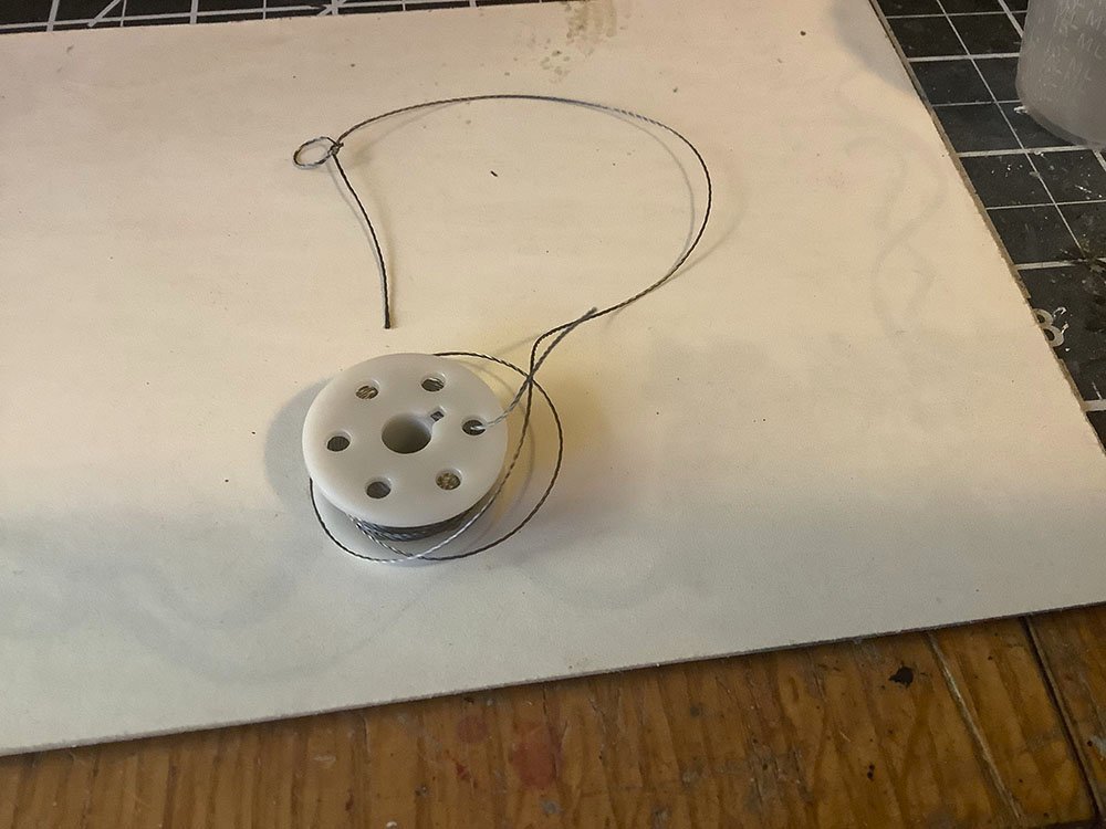
But I might have found a solution I like for all my quandaries about the rigging. I found some "stainless steel thread". I think it is similar to the beading wire but without the clear plastic coating, so a bit more thread like (i.e. more flexible). You can see below that I was even able to tie a knot in it, though the knot wanted to loosen so they will need to be secured with some CA. I have also wondered about using a tiny drop of solder to secure the thread.
When cut, it does unravel a bit. But if you first put a drop of CA where you plan to cut, it does not unravel and is just thin enough to fit through the smaller holes in the photoetch parts. I've not actually attempted to use it on the model yet, just done some experiments with it.
So, what is the source of this stuff? I got it off of amazon but it originally comes from "adafruit". They sell a variety of accessories intended for use with Arduino controllers. This thread is intended to be used if you want to add Arduino controlled LEDs to your clothing. 🤷♂️ I got the "medium" size, though they also have a smaller size as well. Here's a link to the stuff on the adafruit web site: https://www.adafruit.com/product/641
- davec, mtaylor, Old Collingwood and 7 others
-
10
-
Looks like a lot of details there.
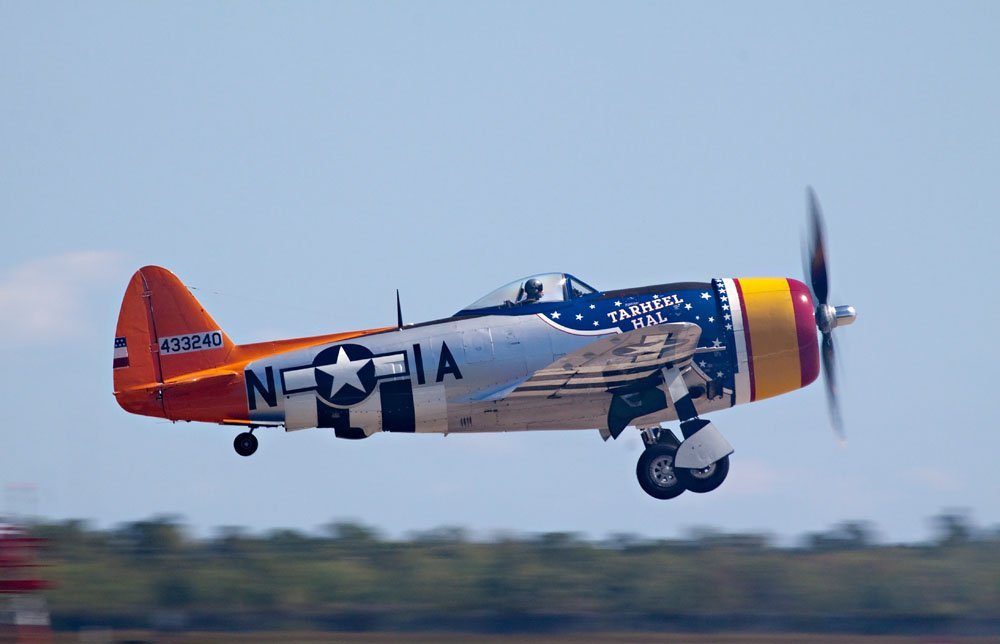
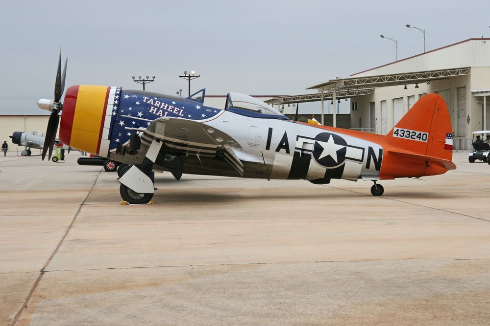
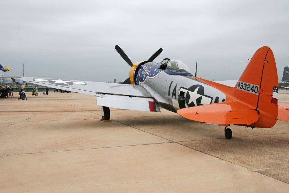
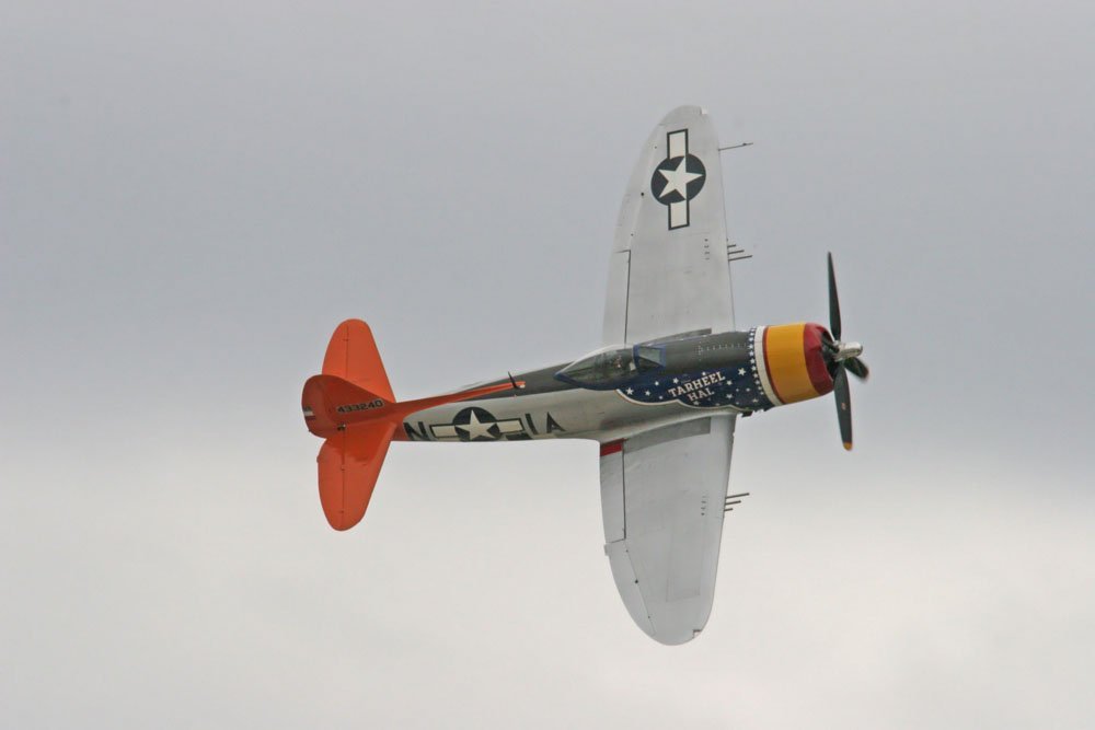
And I thought I recognized the "Tarheel Hal" livery. The first picture below is from the 2011 Wings over Houston air show. The other three are from an air show in 2006 in San Antonio, Tx, I believe it was at Lackland Air Force Base. Back then they had an air show every fall that alternated between Lackland and Randolph AFB, so it was one of those two.


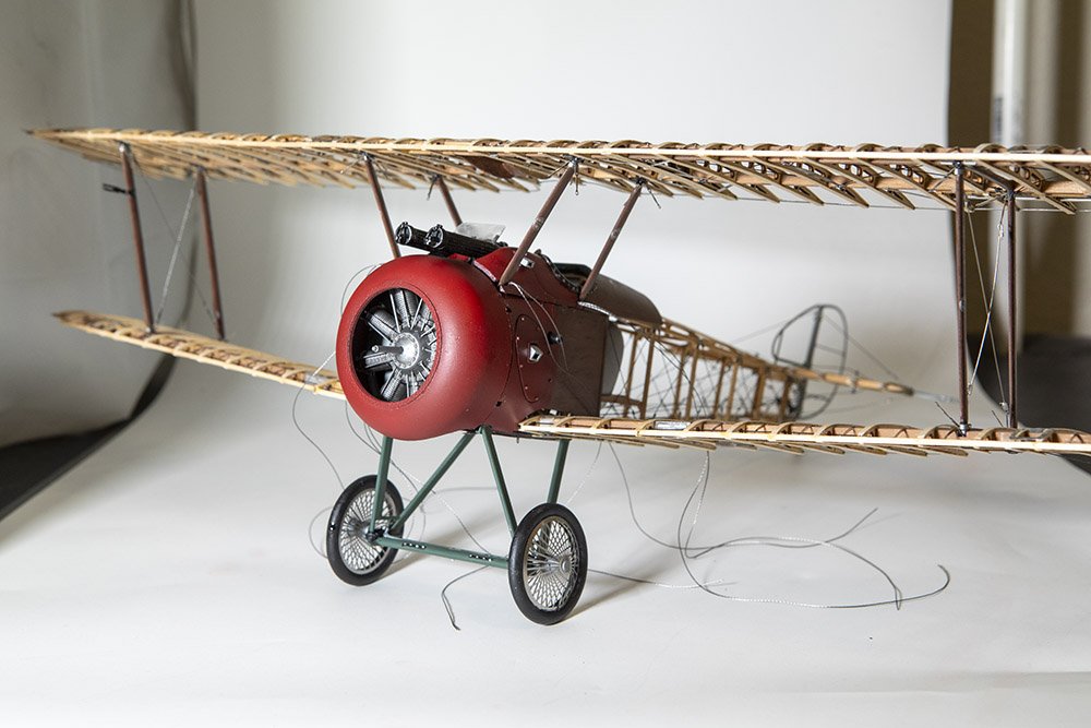
Sopwith Camel by gsdpic - FINISHED - Artesania Latina - 1/16th scale
in Non-ship/categorised builds
Posted
Finished
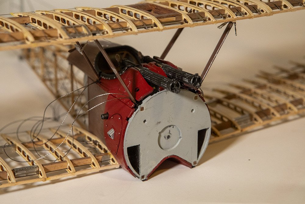
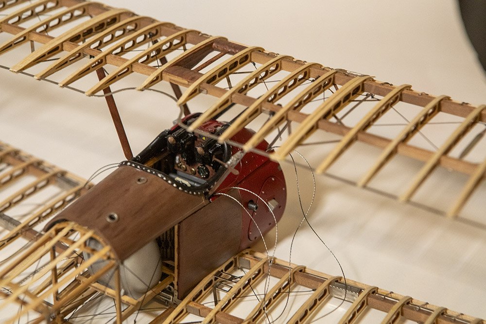
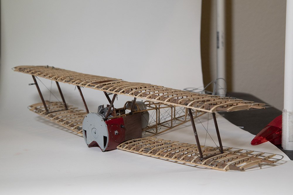
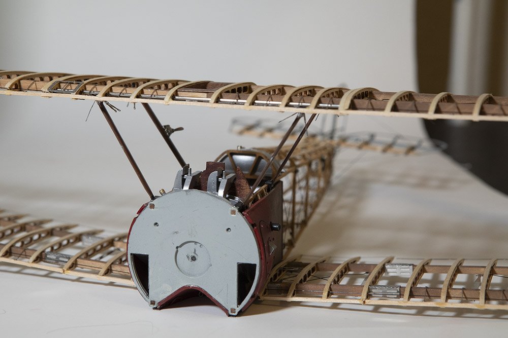
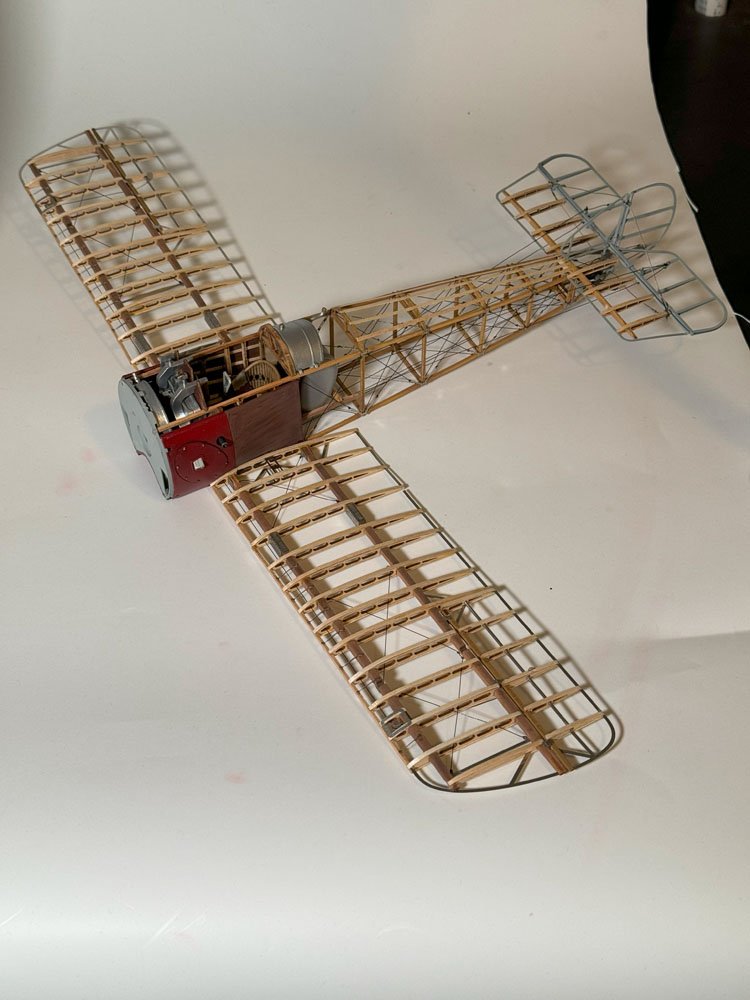
I sort of limped over the finishing line but I am calling this one done. It was a bit of a roller coaster at times but I am pleased with the end results. I completed the rigging, at least as much as I plan to do. There was supposed to be some rigging on the landing gear as well but I am going to leave that off. Overall it was a very good kit with a lot of positives, but just a few really glaring negatives as well. And it definitely had some challenging aspects too....I accept at least some blame for any flaws in the final product.
Initially I had thought about maybe creating some sort of diorama, or at least a base, something like @chadwijm6 created for his Sea King helicopter. I still could do that in the future, but for now I will just display it on the stand once I get the remaining stand parts that were missing from the original kit.
As for the rigging, post #129 of @DocRob's AEG G.IV build log was a great help. I used a lot of those techniques, except with the stainless steel braided thread and slightly larger aluminum tube. I put a bit of CA on the end of the thread to hold it together, then passed the thread through the tube, then through the hole in the model, then back through the tube. I then put a drop of CA on the thread near the eyelet and slide the tube up to the eyelet and it worked like a charm. All that after trying several different types of thread or wire and several different methods of attaching it. That method was easy and also very effective so thanks to docrob for that post.
Thanks also to everyone who has followed along and commented or at least hit the like button.
And finally the pictures. This model is too large for my DIY photo stand/light box so I just put it on a somewhat beat up card table for its photo shoot.