Heronguy
-
Posts
863 -
Joined
-
Last visited
Content Type
Profiles
Forums
Gallery
Events
Posts posted by Heronguy
-
-
-
I'm sure about being able to go slow - steady is another issue 😉
Seriously though you're providing a detailed approach and I will certainly be trying to emulate your success - I'm sure questions will arise when I get that far!
-
Some progress.
I did have to replace bulkhead 28 because of sloppy cutout - it's the only one that seems to have been badly treated on the scroll saw.
The replacement looks better
- bdgiantman2, JpR62, Matt D and 12 others
-
 15
15
-
you are certainly keeping your momentum going David! I’m sure this will be another great build. I don’t find POB rolls off the tongue as well as PdN did but it is better than pobpob🧐
-
Thank you Popeye. Your continued interest in my projects is appreciated. I still don’t get useful stretches of time to focus on builds but 15 minutes here and a half hour there do eventually add up.
-
I agree with you Chris. The kit design seems well thought out and the kit contents are really good. I must admit I was attracted to the overall size of the Stefano from a build perspective without giving thought to the size from a display perspective. One might assume it will be on the bench so long that it won’t be my problem to arrange display. As a relative newcomer to modelling I’m not sure I’ll give it its proper due but I’m enjoying the process.
-
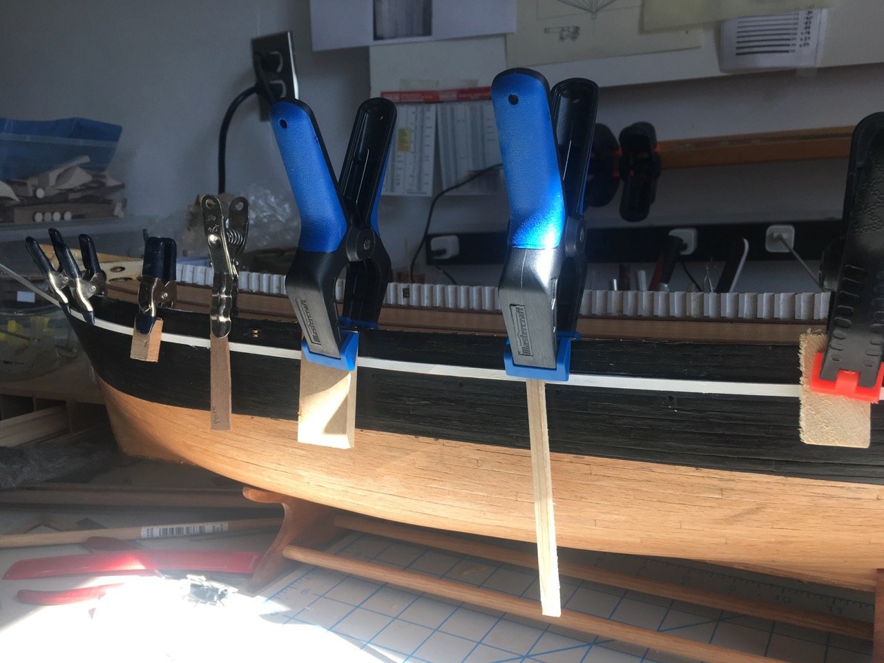
The bulwark went on without much trouble. The holding jigs worked well enough. If I were to repeat this I would have used a harderer wood for the jigs since the roasted poplar I had lying around split under minor pressure and had to be glued back together a couple of times. When it came to clamping near the bow and stern (where the rails curve) I cut the jigs so that they were not as long and could follow the curve better.
- rafine, JpR62, popeye the sailor and 5 others
-
8
-
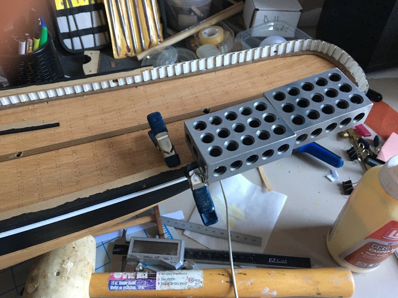
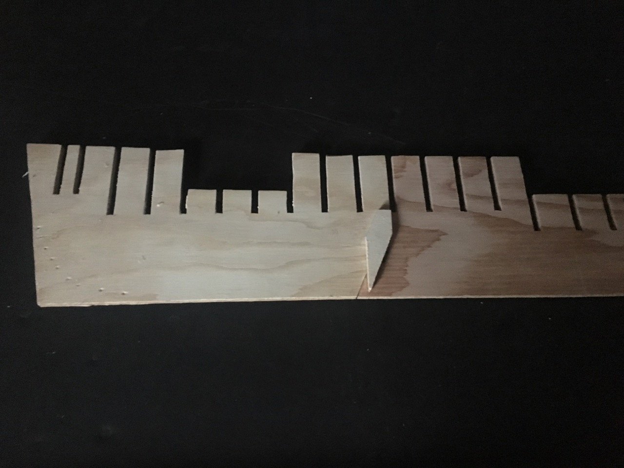
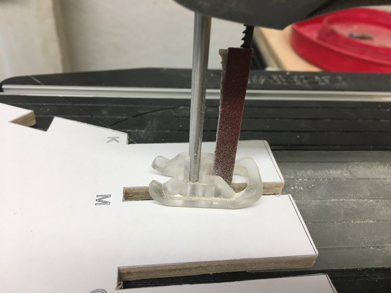
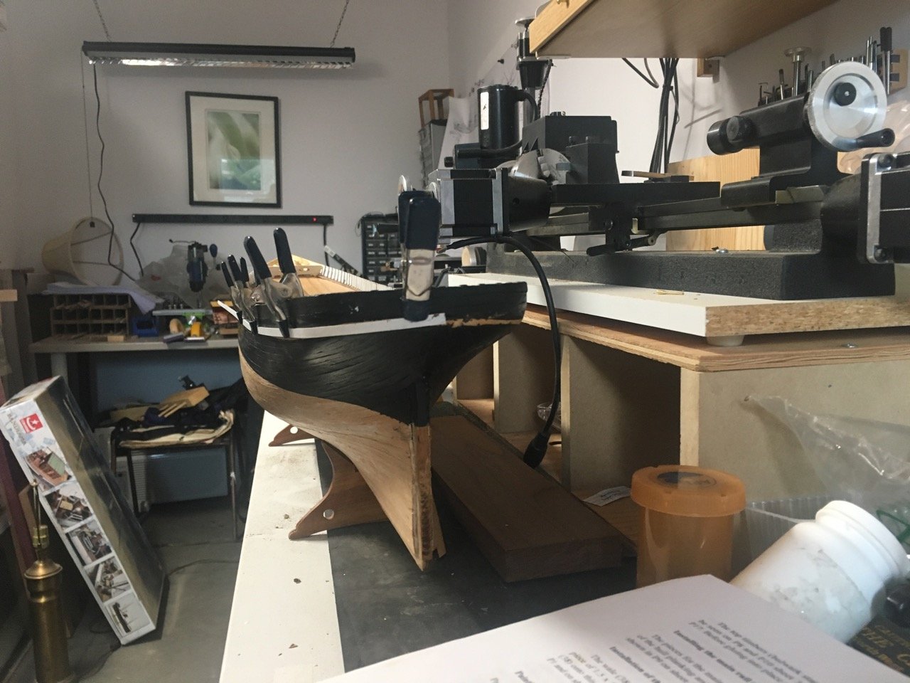
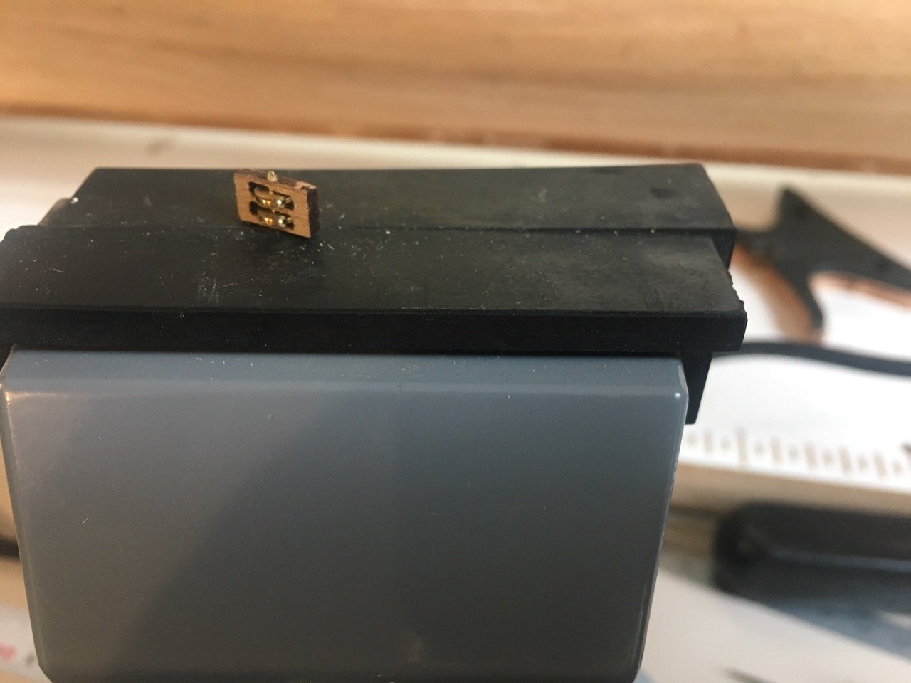
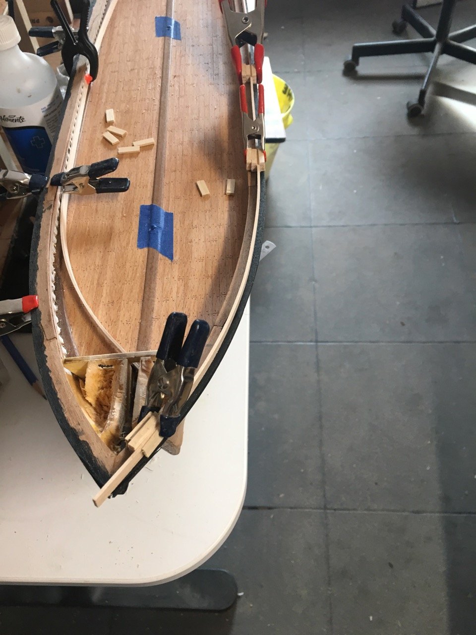
The next challenge is mounting the topgallant bulwark onto the toprail. The bulwark is a 1.5X5mm strip that is glued on its narrow edge to the toprail. Getting if to sit properly for glueing seems a bit difficult.
1st thought was just to clamp it with some shims.
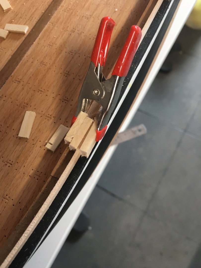

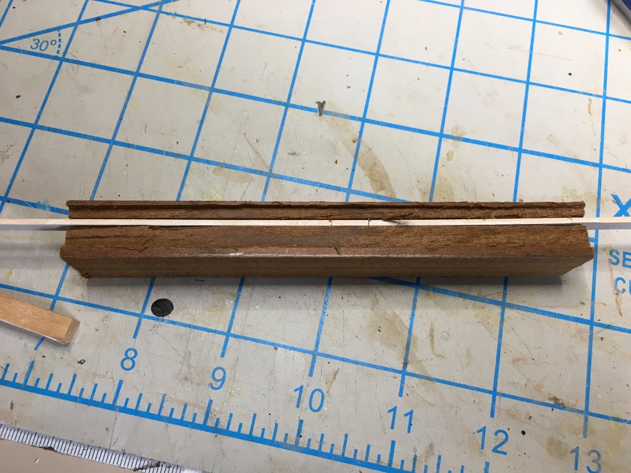
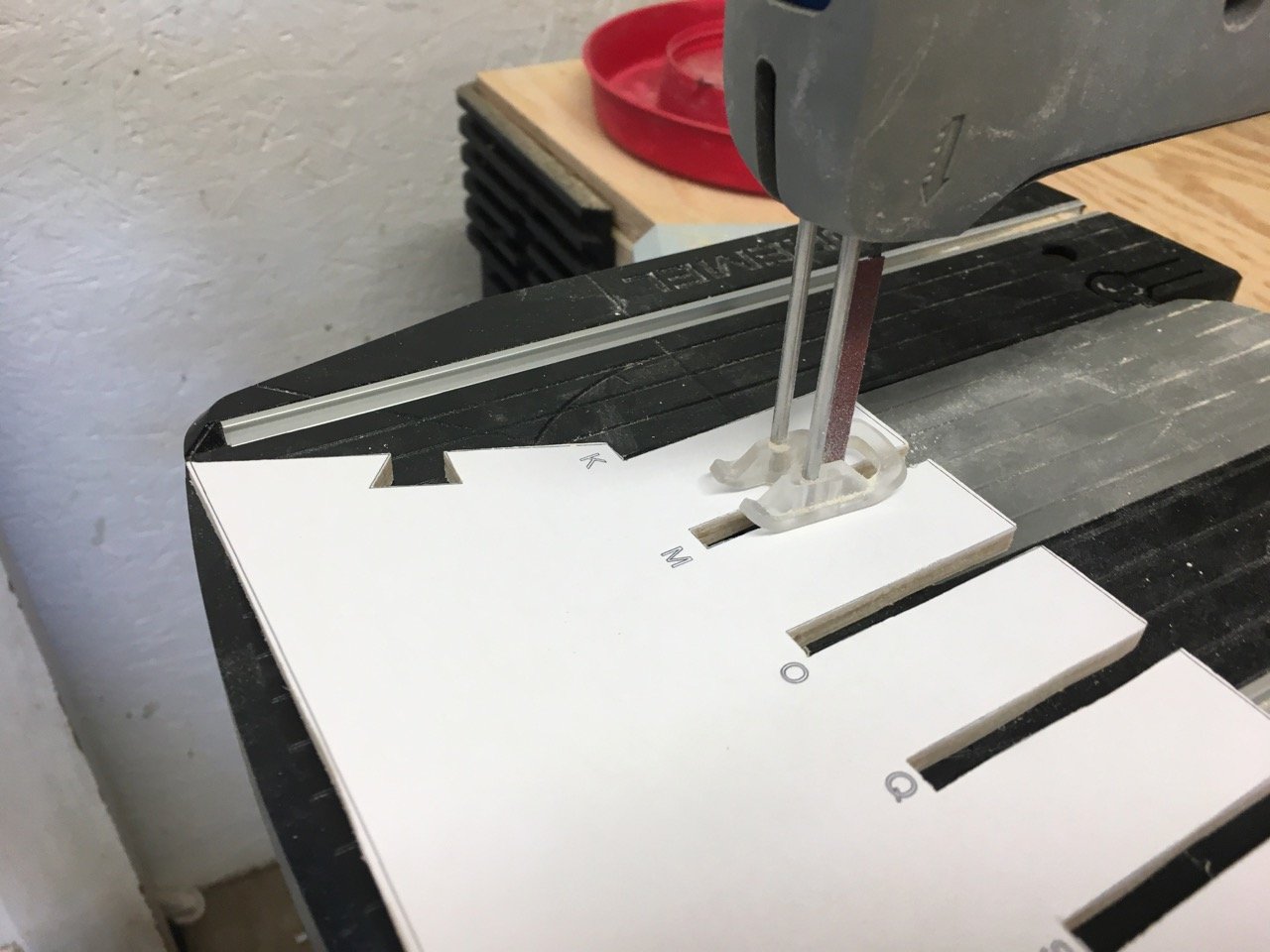
That looked like it would work but was a bit fussy to hold, position , and clamp without things slipping out of place. Refinement of the method was to mill a one-piece holder.
The groove will hold the bulwark strip and th4e channel above it will position it on the top rail.


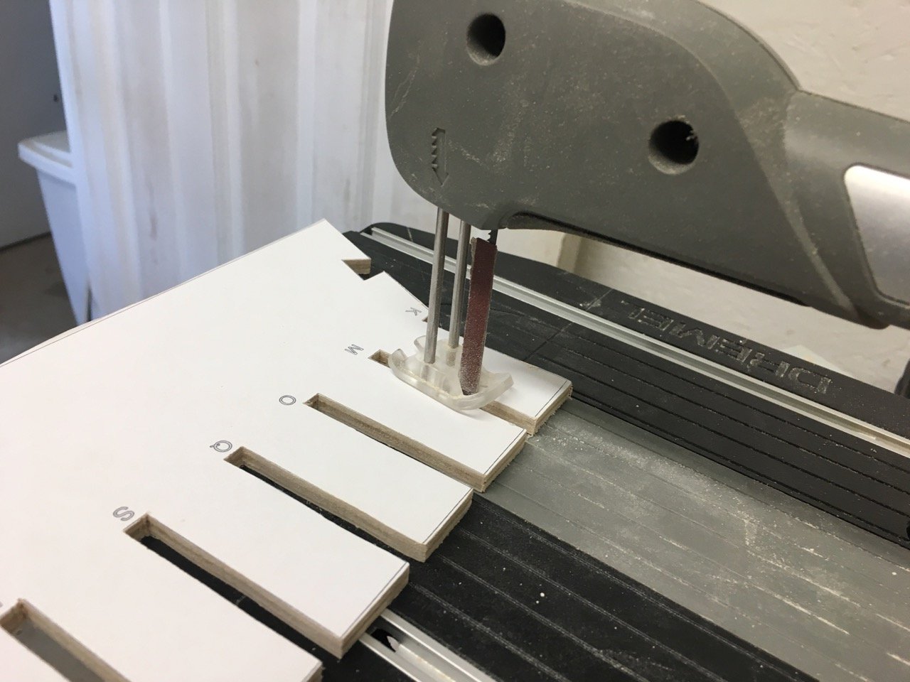
I cut it into 4 pieces to space out along a section of the bulwark.

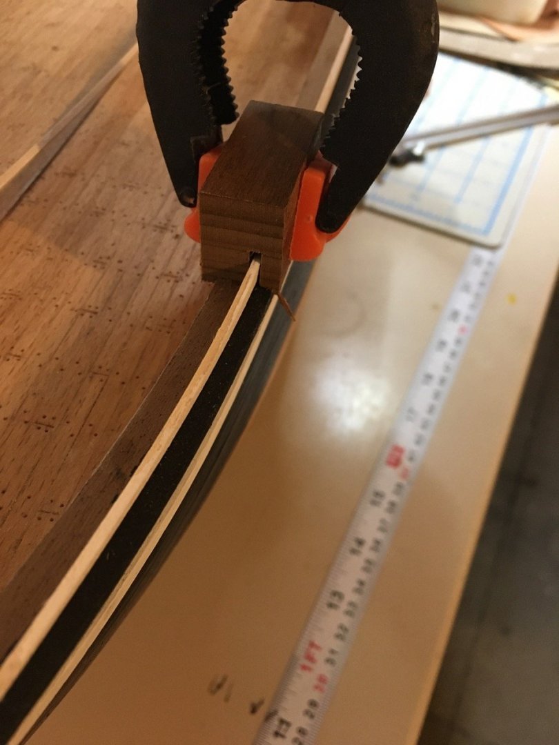
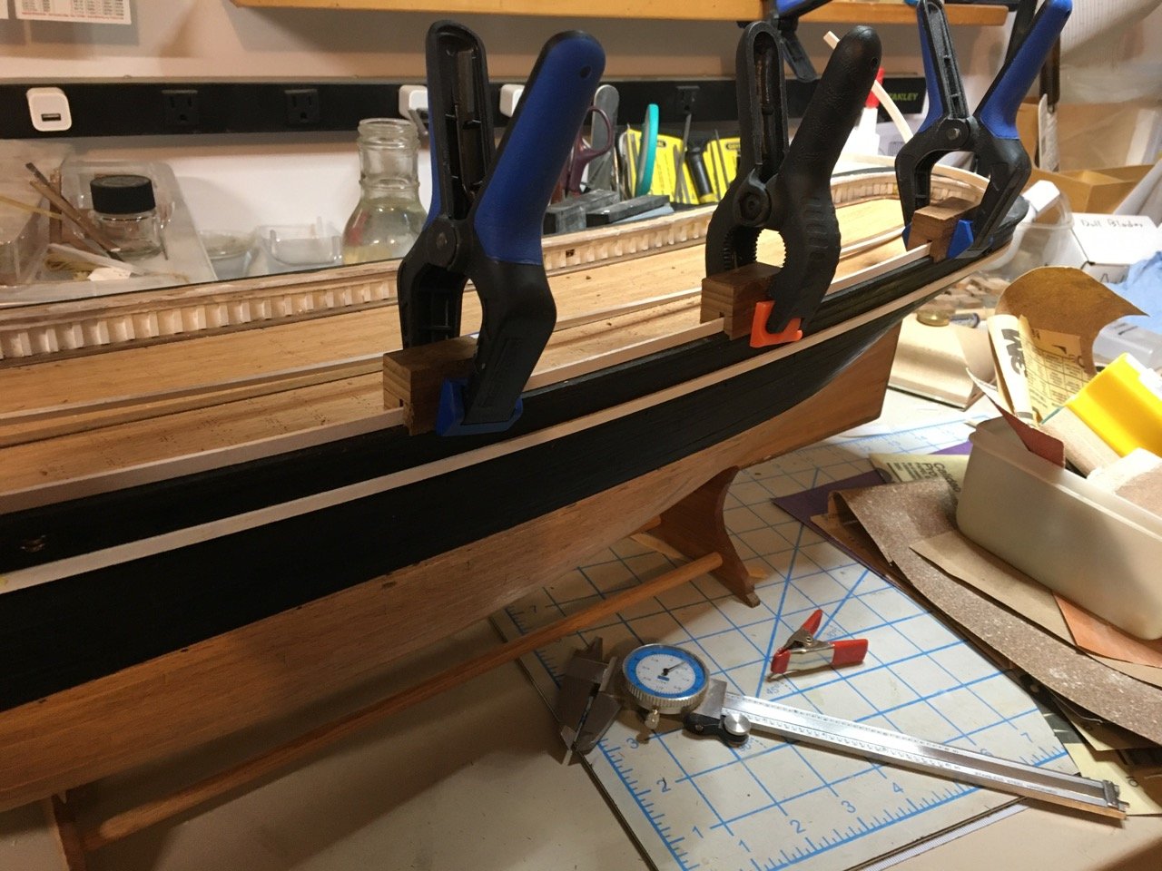
The small clamps create the downward pressure on the bulwark while the glue sets.
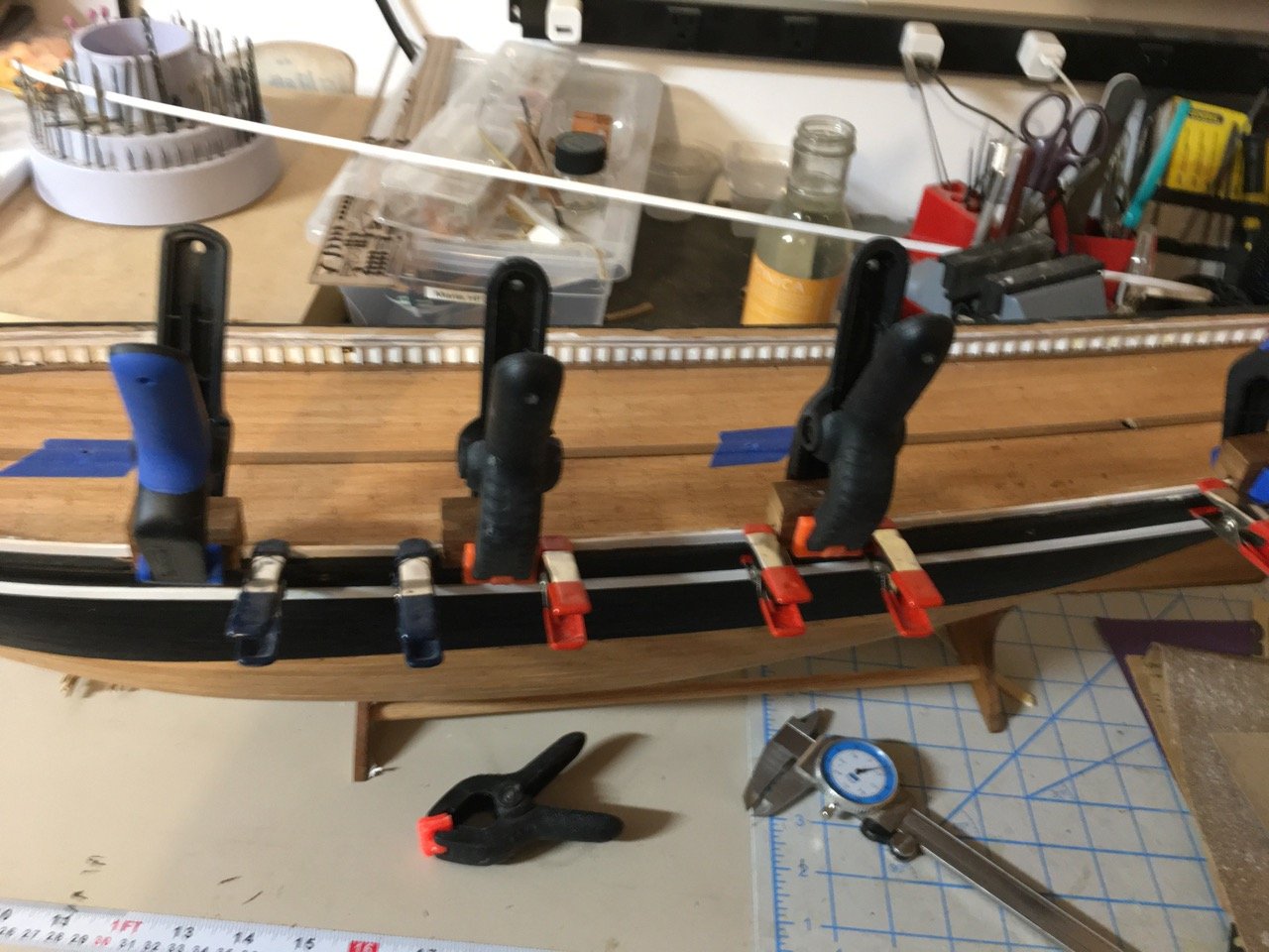
Hopefully tomorrow morning will validate this effort!
- popeye the sailor, Tom E, robdurant and 3 others
-
6
-
I've done 2 copies of the bulkheads and BF (plywood was too thick >1/4"). Definitely improved the job I did 2nd time. Yours already were well cutout so you'll just have to chalk it up to "experience". 😀
- FrankWouts and Matt D
-
2
-
Added the toprail that simply glues to the bulwark and top timbers. It is laser cut and comes in sections
I started at the bow and added sections to the stern. There wasn't quite enough overhang at the stern to I added a small section and blended it into the rail.
The wale rests underneath the top rail.
At the bow I had problems with the wale just underneath the top rail. I had to chisel out a some of the planking to allow the wale to fit nicely. I didn't feel very confident when I started that fix but thankfully wood is fairly forgiving and you can hide hacks underneath the new strip!
-
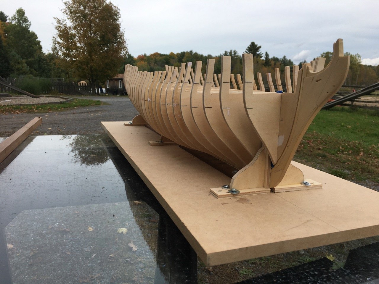
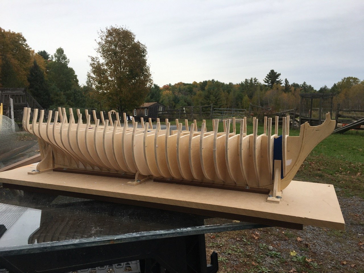
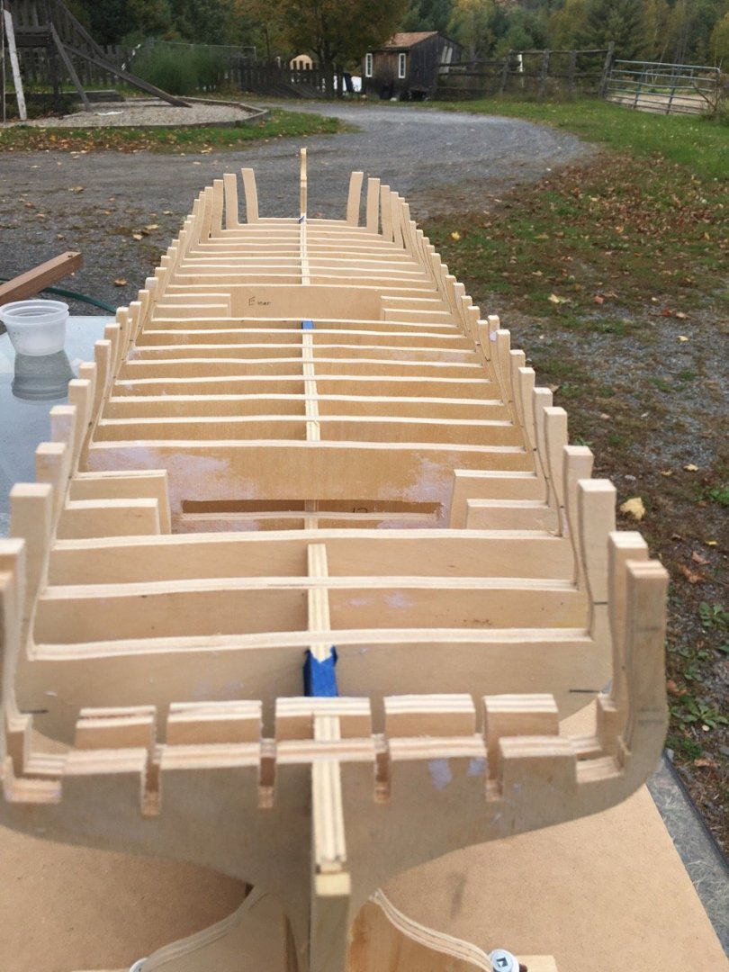
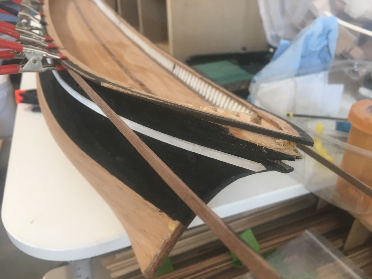
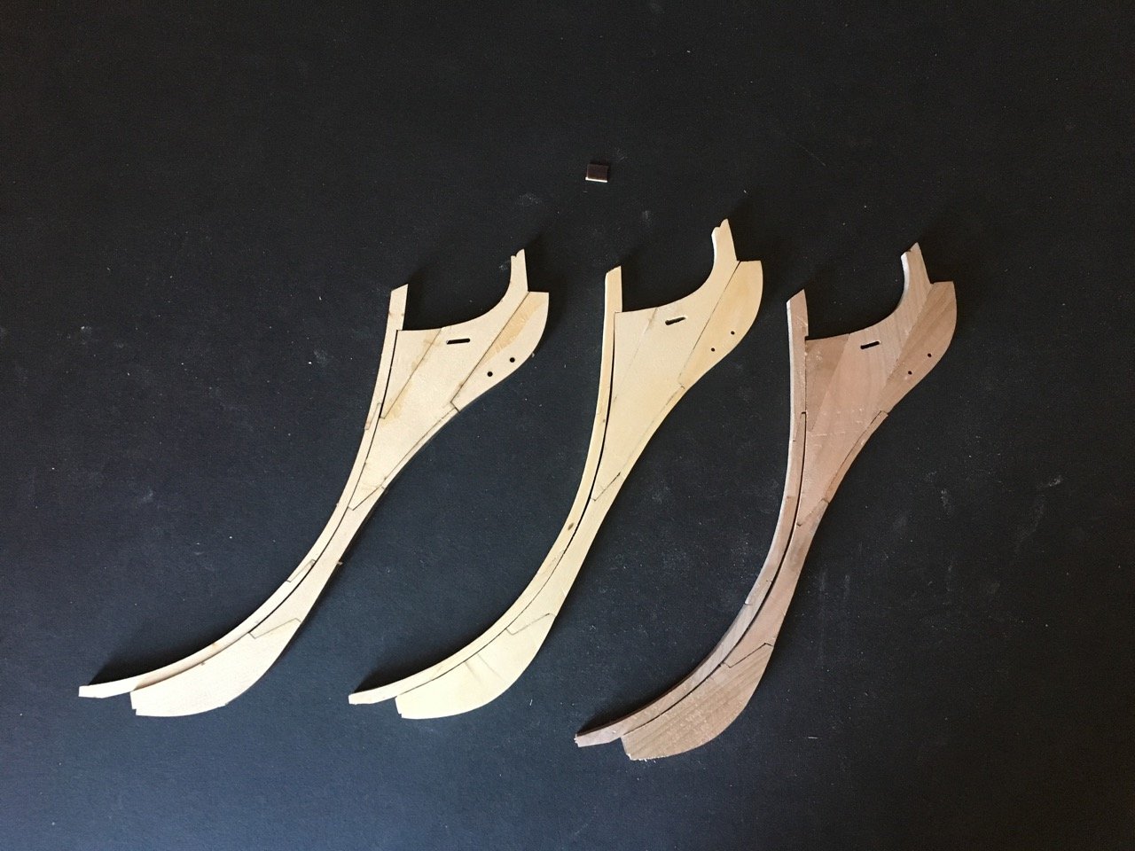
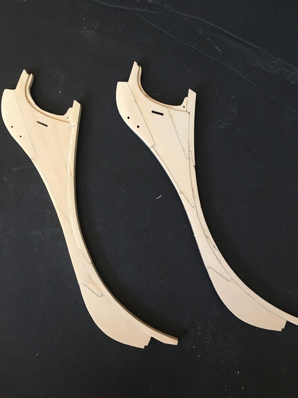
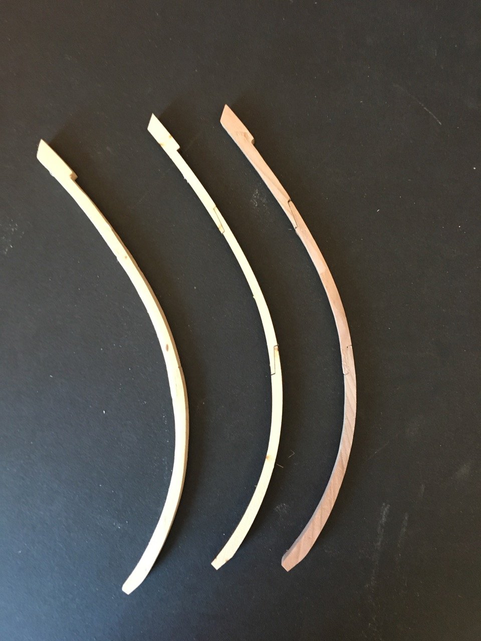
Finished the stems.
AYC - scratch and laser cut versions

Cherry and AYc laser version

Since I still have 2 "skeletons"
I had an incident with the one bulkhead former when I dropped it. The stern section snapped off at the joint. I made a repair by glueing a reinforcement over the joint. It seems robust enough!
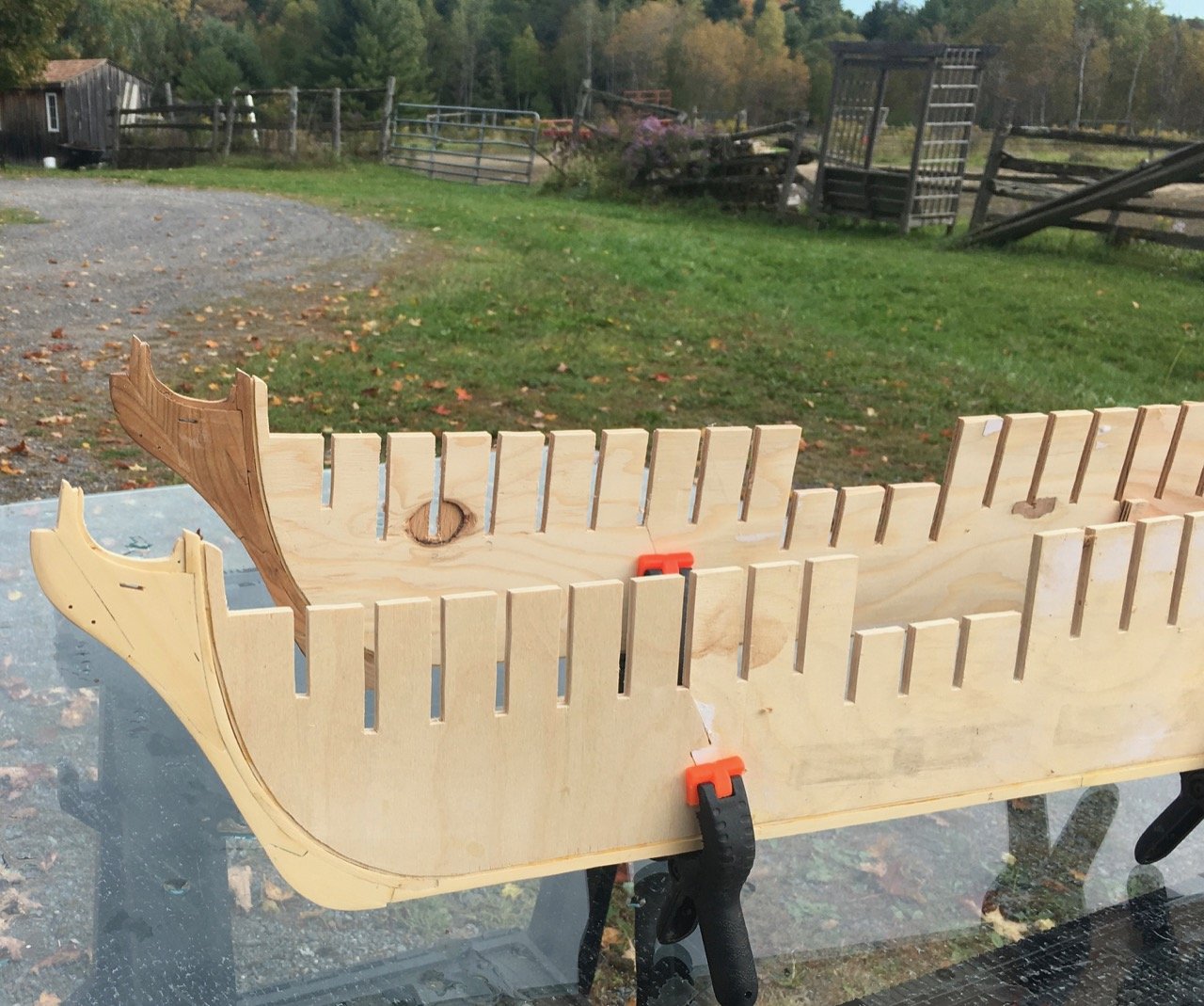
On to the building board!
- FrankWouts, rafine, Chuck and 9 others
-
12
-
Well done David. Congratulations on another beauty.
-
No idea what I'll do just yet. I like working with the cherry wood but the cedar seems like it will be much easier to work with when I get to planking. Since I have 2 "skeletons" I might keep on dressing each one until I get worn down.
- Chuck, FrankWouts and tarbrush
-
3
-
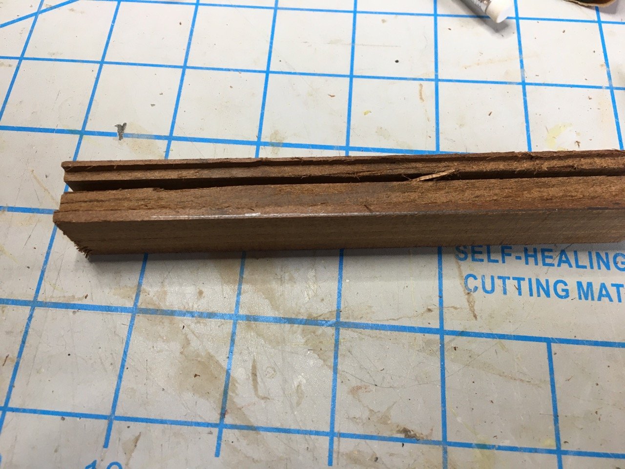
I have a goal of trying to scratch build as much as possible on this project. Although I have some Alaska Yellow Cedar purchased a couple of years ago I don't have a bandsaw for resewing the board. I'll be ok for strips for planking but the larger sheets for the stem and other components is a bit more challenging. Being concerned about the sheets I was going to order some from Syren but must have been seduced by the laser cut material for chapter 1.
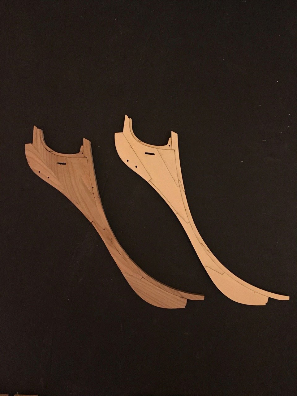
When I got the order from Syren I decided that I had a great backstop with the laser cut stem so I may as well try my hand at scratching the same pieces.
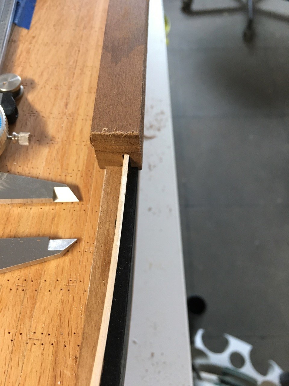
I only had 3/4"x2" wide cedar so I cut down the billet on a table saw and thicknesses to 1/4"
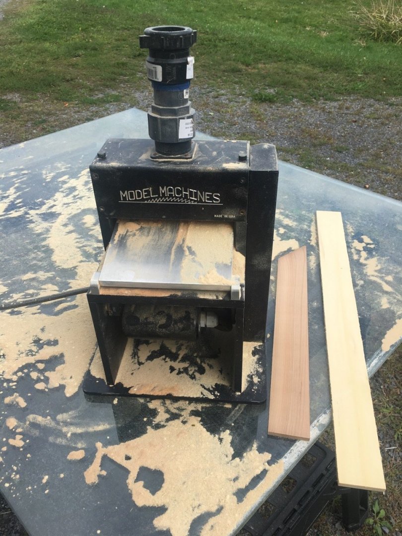
While I was at it I also did the same with a piece of cherry
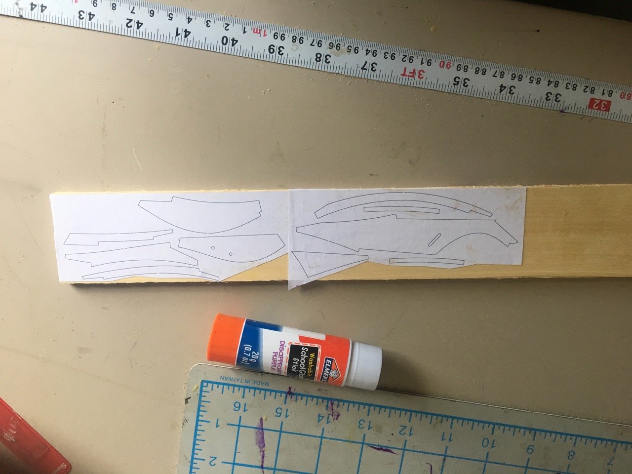
My version and the laser cut sheet
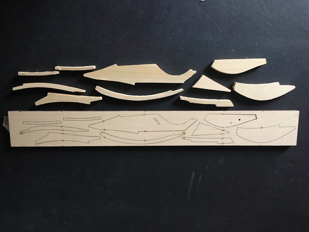
I wanted to see what the cherry version would be like.
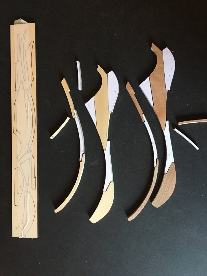
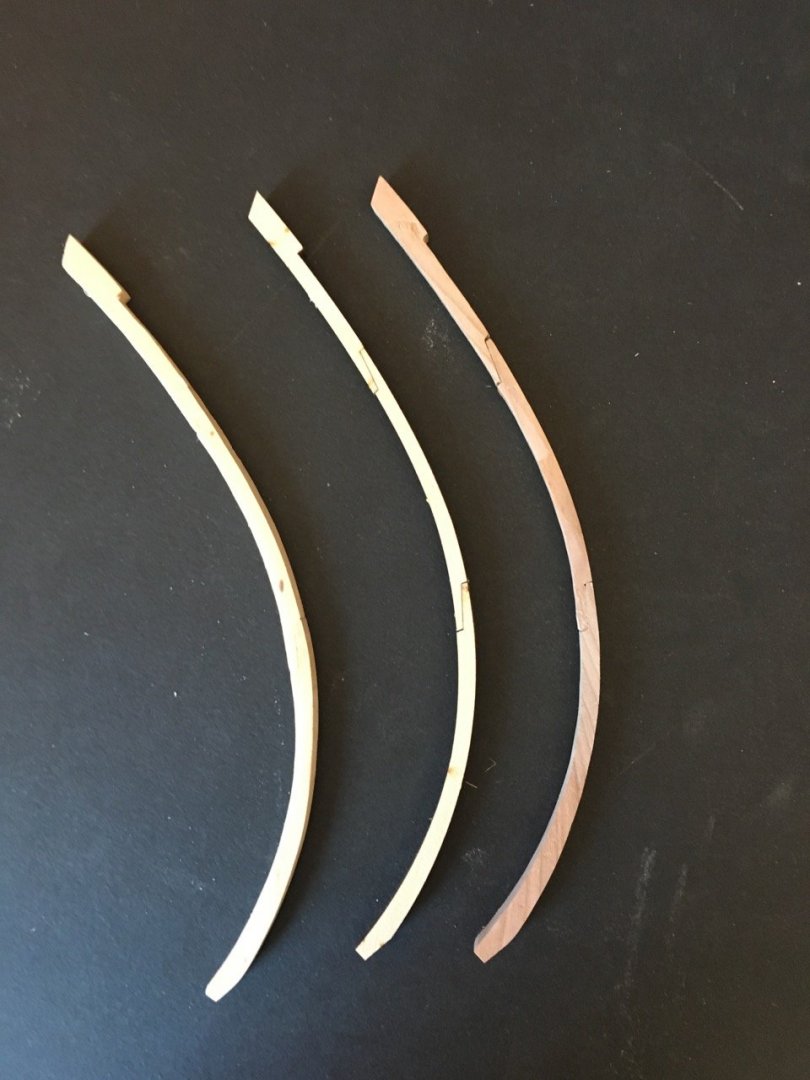
The laser cut version is clearly superior in precision of fit and with the laser char defined joints. My cedar version is not too bad. My cherry version demonstrated to me that once would have to be very careful matching colour and grain to get a consistent look.
- tarbrush, Rustyj, FrankWouts and 5 others
-
8
-
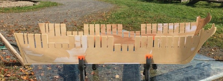
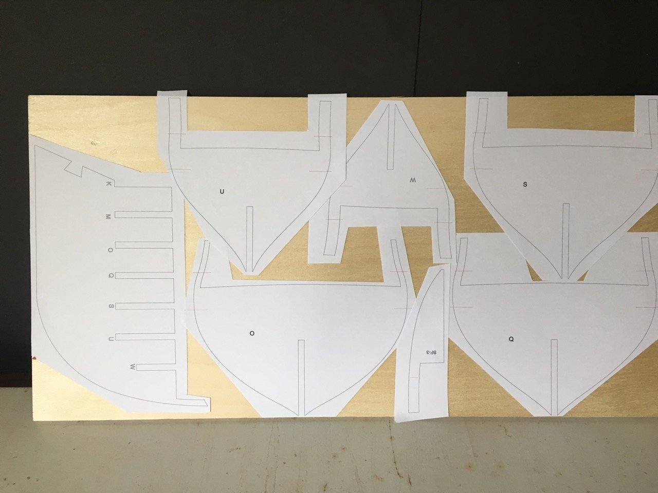
I now have 2 sets of bulkheads and bulkhead formers cut out. I tried running the bulkhead former made from the >1/4" plywood through a planer to thin it down as an experiment. Not too bad a result but I used a belt sander to take if down a bit more. I haven't yet tried to use the belt sander on the bulkheads themselves though I may today.
Meanwhile I've been dry fitting the "new" bulkheads. About 1/3 of them are done.
-
-
There a several builds on this site. In addition when I was starting my build I found the following site:
Online I found a set of articles on this model produced by John H. Earl (http://www.modelboatyard.com/bluenose2.html). I decided to follow his instructions.
(John is also an MSW Member).
There are a couple of versions of the AL Bluenose II that differ from each other. The kit I have was #20500. The newer one is #22453.
I have the 20500 manual that someone sent to me since my kit was missing the english language instructions. If you have that version I could forward them to you.
-
Ya can’t steal what’s freely given!
I agree that it works well on the slots. I was using a sanding stick and found it was splintering the plywood a bit. This method worked much better for me. (Quicker too)
-
I have received the new plywood. I'll have to get back to the print shop to get the 11x17 sheets but I have lots to do 'til then. Now starts the task (2nd time around) of cutting and sanding the formers and bulkheads.
I came across a YouTube video of a DIY scroll saw sanding blade. The trick was double sided tape and a used saw blade. Seems like a useful way to clean up the areas where neither the disk sander or spindle sander will reach.
- FrankWouts, Gregory, Jack H and 13 others
-
16
-
Denis, Don,
It's nice to be back at it. I hope the momentum will build.
When is your Stefano back on the bench Don?
-
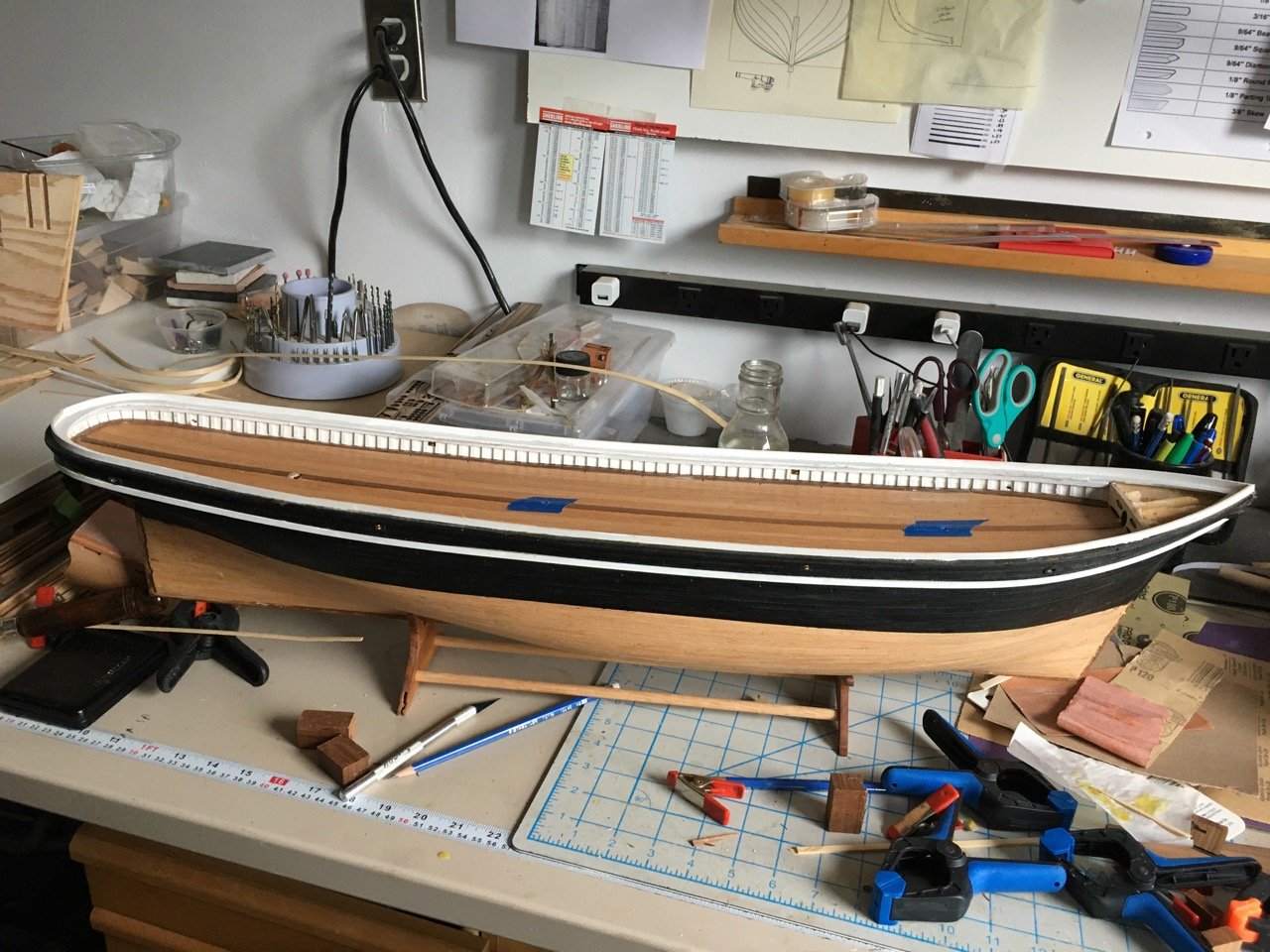
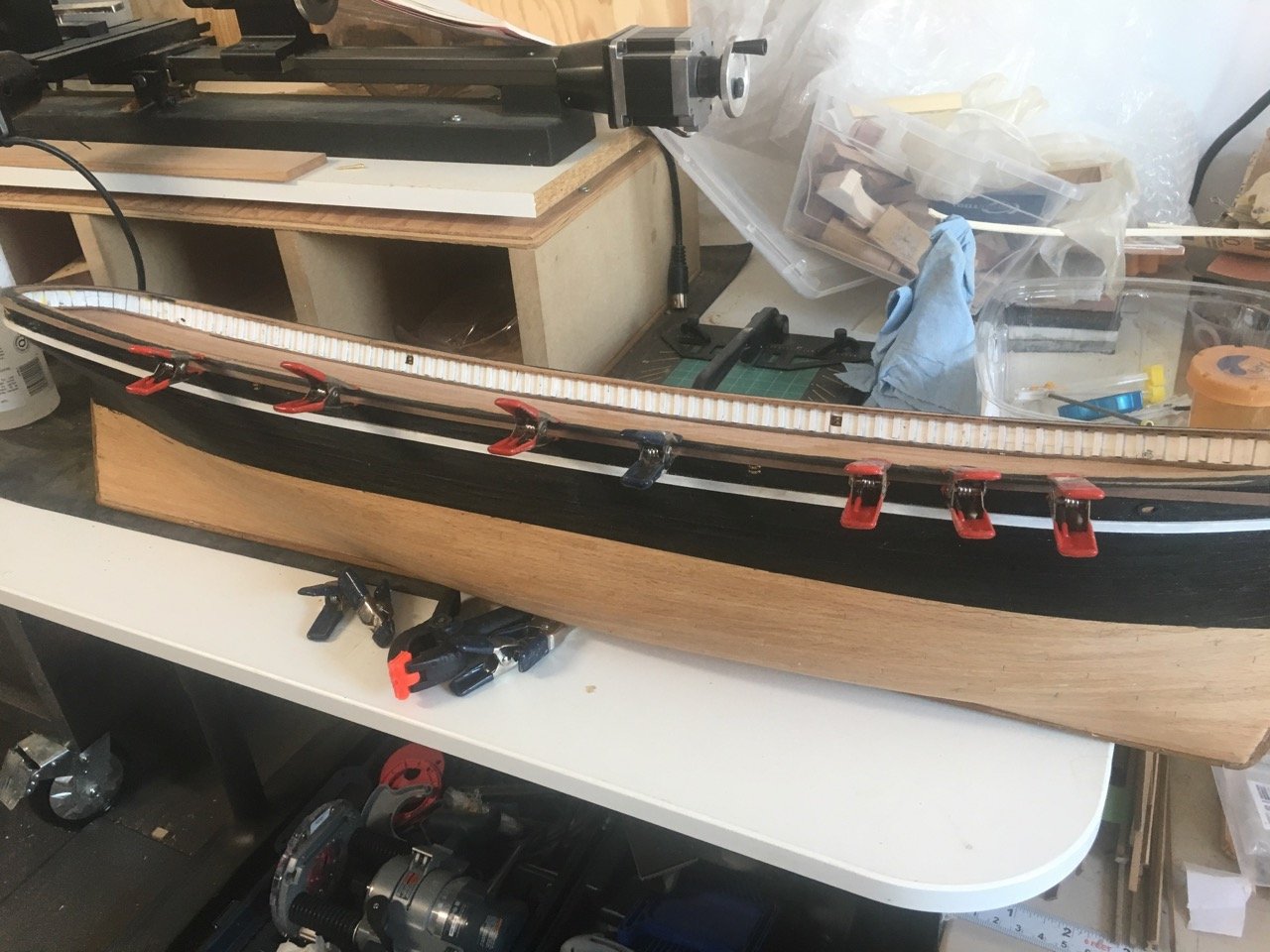
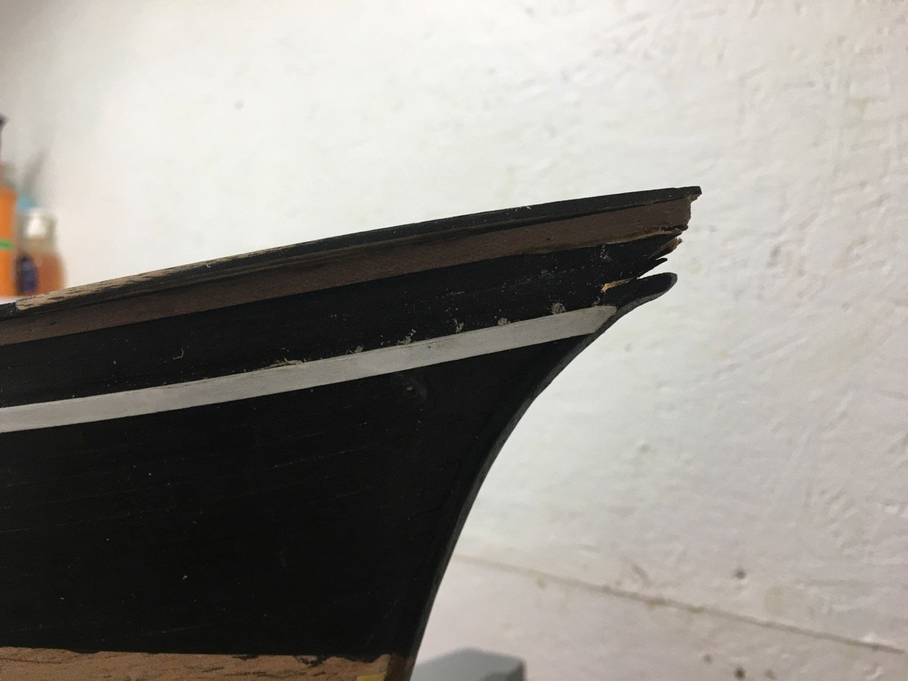
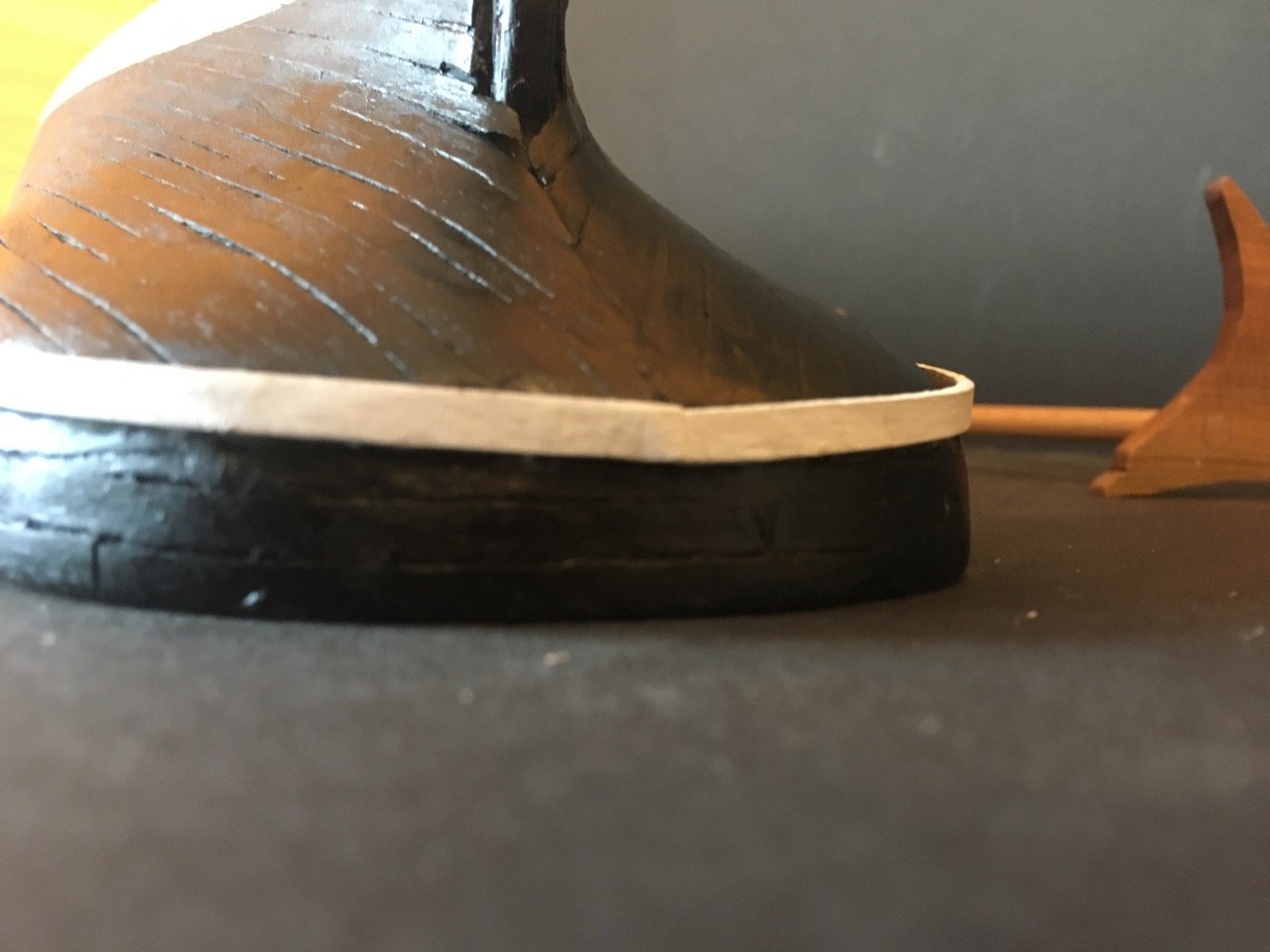
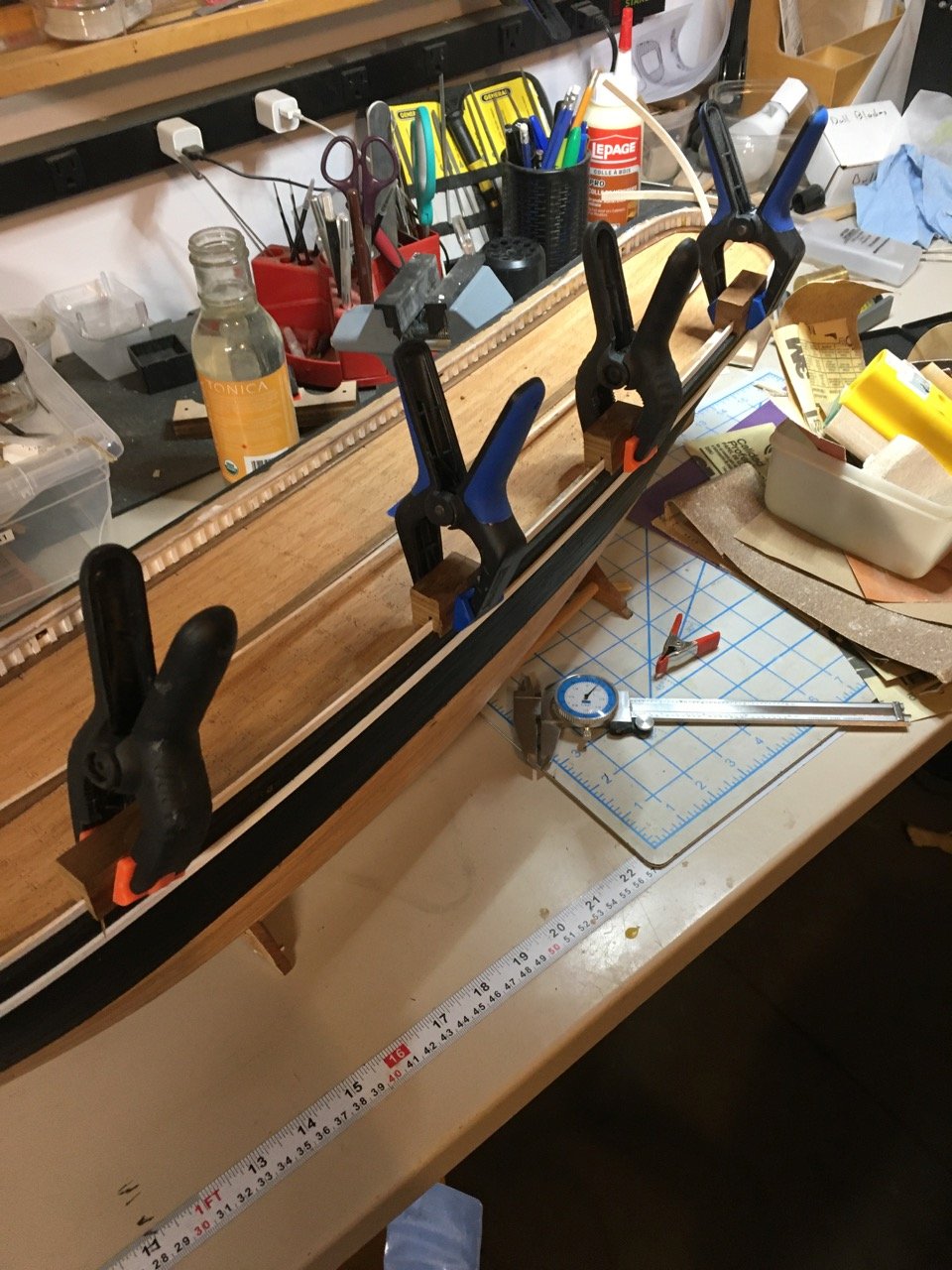
Once the waterline was established the hull above was painted black.
It was time to install the wale (called a rubbing strake in the instructions). This proved to be a bit of challenge for me. I was aware from early in the build that I may have made the stern curve too soon losing a deep enough flat (vertical area). Once the planking was done I was thinking I "got away with it" but it came back to bother me in fitting the wale.
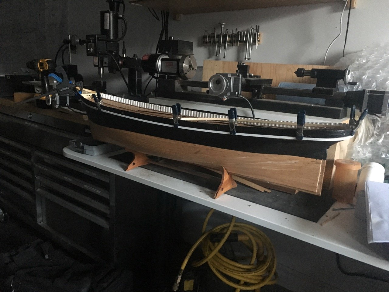
I just couldn't get the run of the wale to work out
After much agonizing and fiddling I pushed ahead
and finished the task.
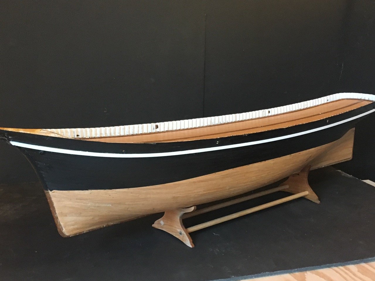
Although the wale at the stern does not lie flat on the hull I think from the normal viewing perspective (i.e. slightly above looking down) it looks OK.
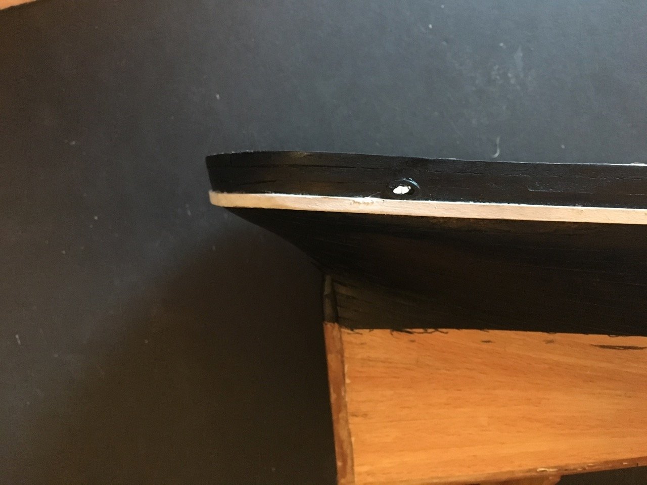
However the gap is there and is pretty obvious on close inspection. A compromise in favour of my sanity.
- Zarkon, Haliburton, ccoyle and 2 others
-
5
-
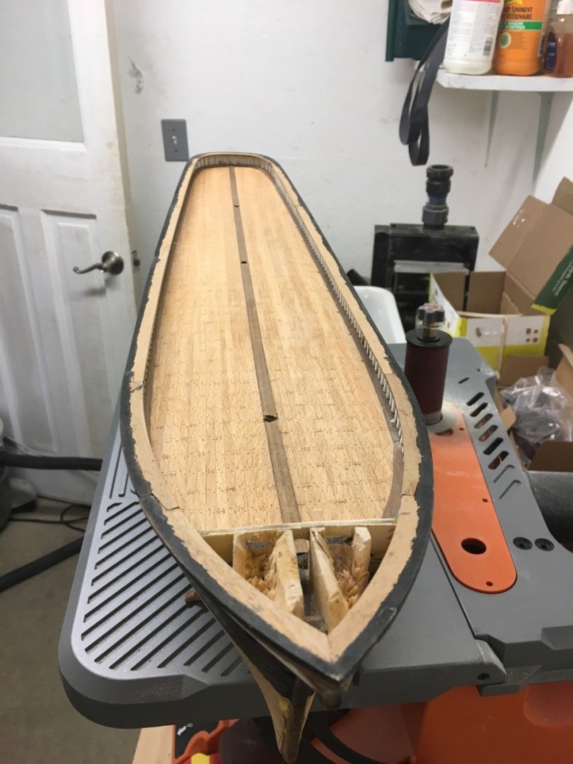
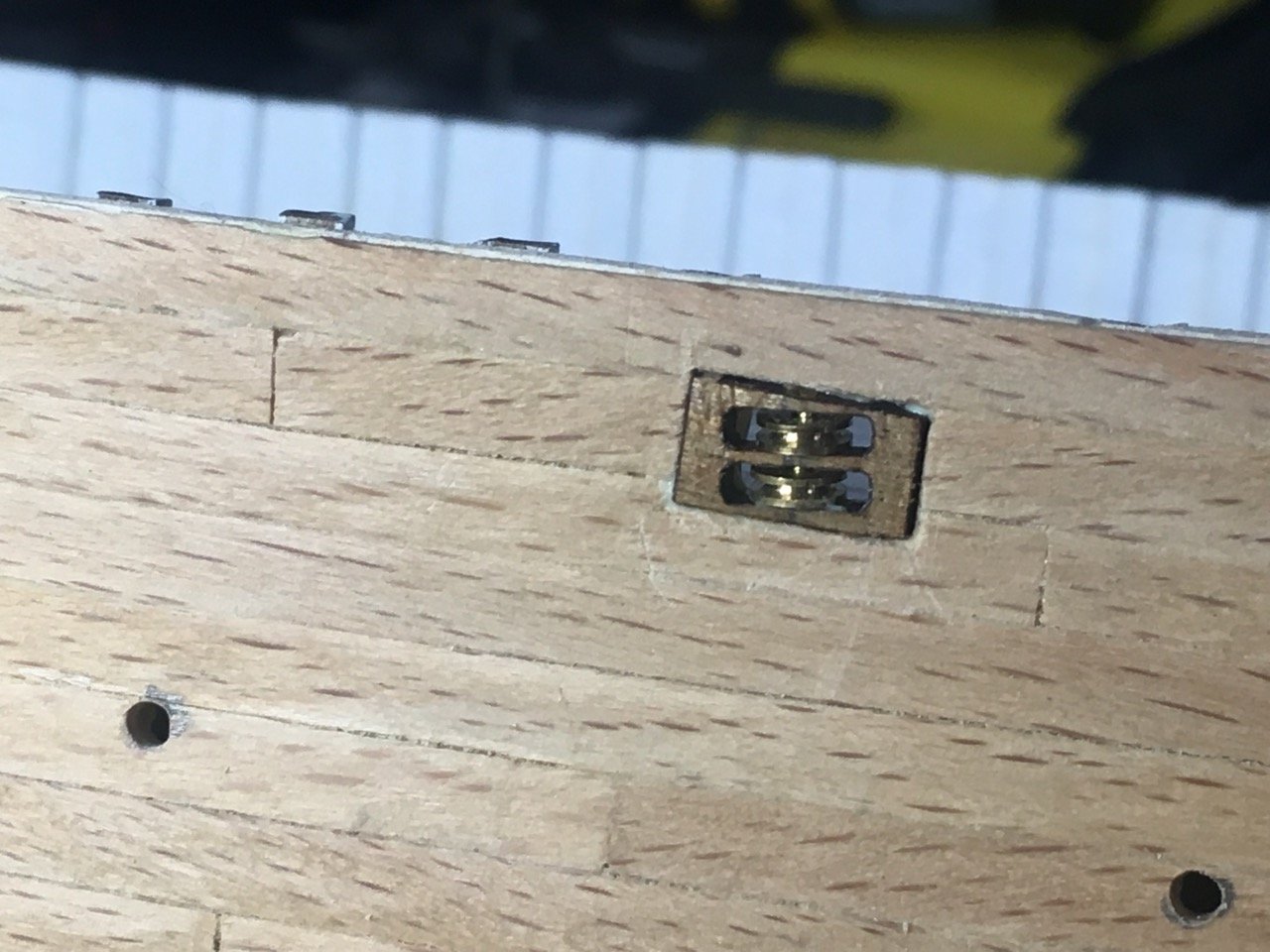
Once the timbers were in place it was time to drill some holes in the hull (mooring line openings, scuppers, anchor shafts, rudder post etc) and assemble the blocks
-
-
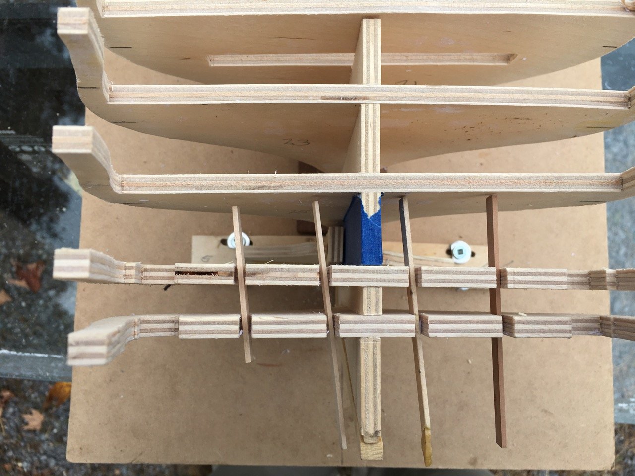
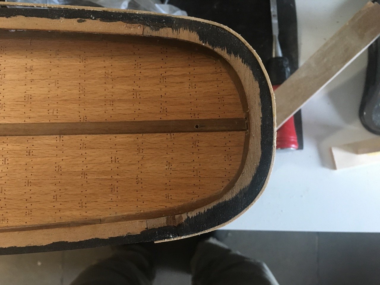
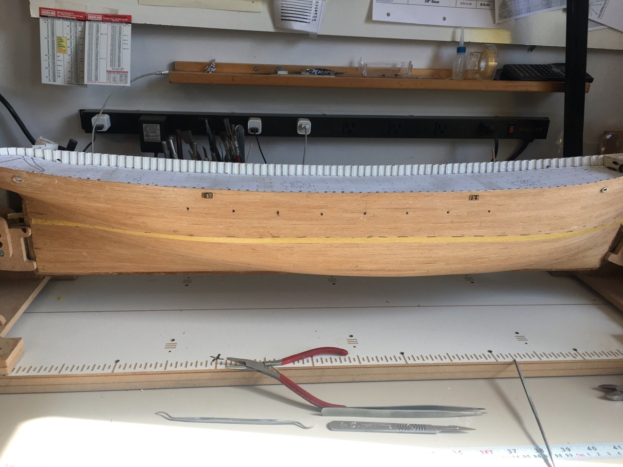
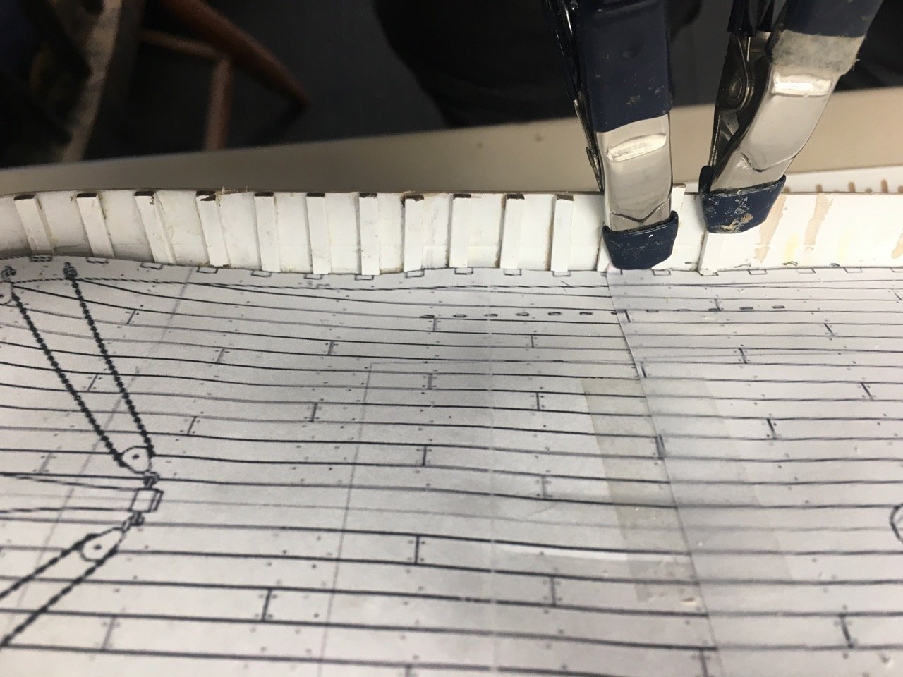
To position the top timbers I printed out the deck plan and used it to guide the installation. A small jig was used to place the strips vertically.


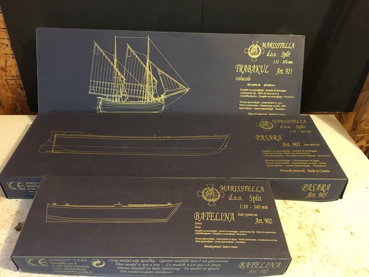
Some lower cost offers from MarisStella. Very limited!
in Traders, Dealers, Buying or Selling anything? - Discuss New Products and Ship Model Goodies here as well!!
Posted
An early present in the mail today! Thanks MarisStella (Zoran)