Sharpie
-
Posts
69 -
Joined
-
Last visited
Content Type
Profiles
Forums
Gallery
Events
Everything posted by Sharpie
-
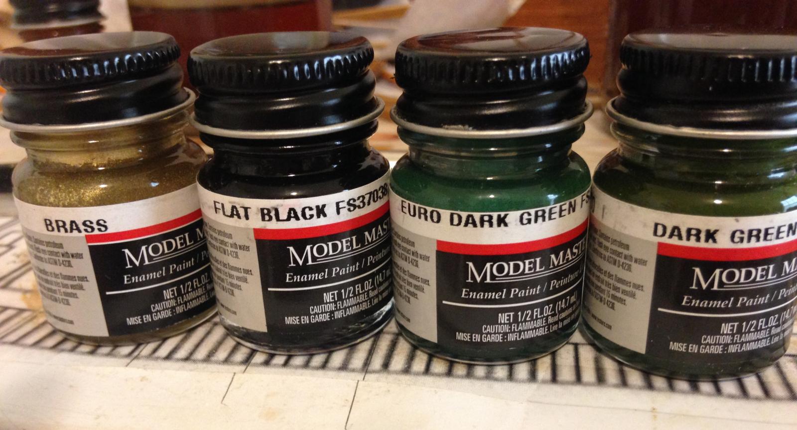
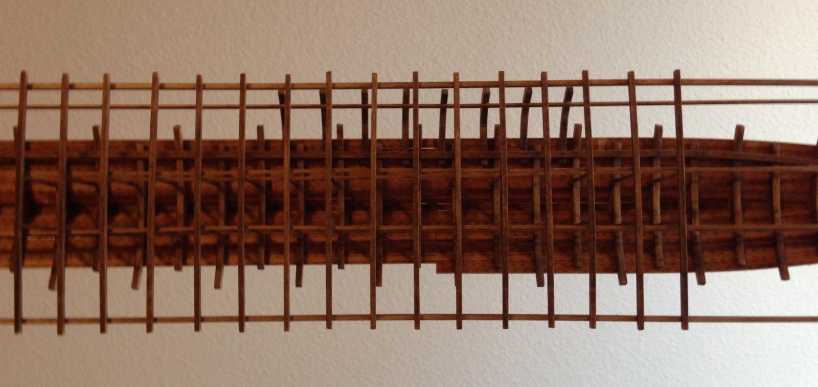
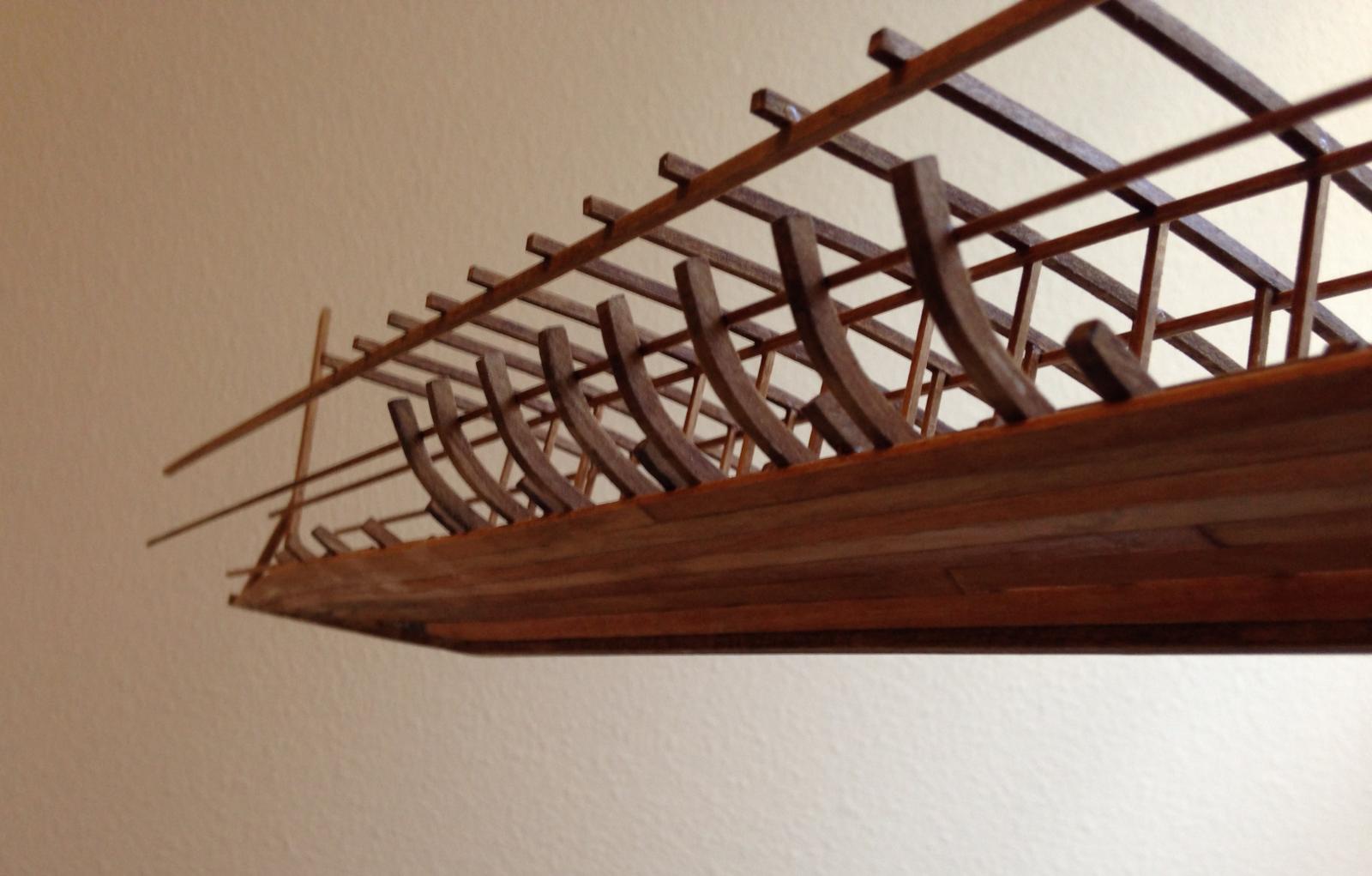
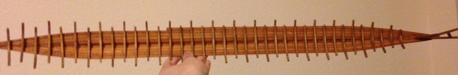
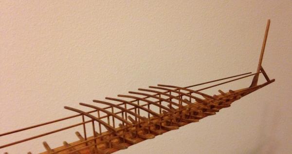
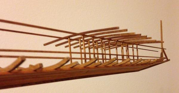
 Thanks David-- though I don't do nearly as much planning as I probably should! Of course, in ancient times, they probably didn't have much in the way of technical drawings. Here's what the ship looks like as of this afternoon: All of the middle rib sections have been installed except for a few in the back. I'm in the process of cutting those out, and they'll be installed in a day or so. After that, all of the upper rib sections need to be made, but I can save a lot of time by cutting the central ones in stacks of four or six and the fore/aft pieces in pairs. The hull planking has been coated with wood filler in preparation for the black paint. I've decided to hold off on sanding it until the rest of the planking has been added. So far, 36 lower deck beams are in place. There will be 6 more at the stern, two of which I've already made but not installed. Here's a view looking towards the bow: One of the major areas of focus right now is getting all of the rowing bench seats made. There are a total of 180, and each seat is made up of three parts, for a total of 540 pieces. It's not quite as bad as it sounds though; I made 50 seats just this morning. I put in one set of seats to check spacing and alignment relative to the beams, and it looks alright to me. All of the pieces that the seats attach to have been cut to length, but I'm waiting to put them in until I add the reinforcing wale at the waterline, which will make sure all of the middle rib sections line up properly. I've also made a few oar shafts, to make sure I can reliably taper them without breaking them, and achieve a somewhat consistent end diameter. The looms will be proportionately shorter than on a trireme, mostly just for spacing reasons. To make them any longer, the thole pins would have to be placed on an outrigger, which would necessitate hundreds more pieces. If every rowing station was fitted with an oar, there would be a total of 90, but I think I'll omit a few of them, both to allow a less cluttered view into the non-planked portion of the hull and to save time. In addition, I've made a lot of progress on the wooden screen that would have provided ventilation and protection. I've made a full 24 inches-- one side's worth. Depending on how pressed for time I am at the end, I may leave off some on the starboard side for better visibility into the lower deck area. Following Ships88's example in his Greek Trireme build log, I picked up a few colors of paint to be used on the ram; I'll be mixing the brass and black to get bronze, and I'll try (on a scrap piece first, of course!) dry-brushing some green over it to create the appearance of a patina. ship ballista test fire.MOV Looking back over the thread I realized I never uploaded this. I don't have a Youtube account to post it there, but I've attached the file. (I decided not to risk breaking the ballista again by stressing the articulated joints, so I just fired it by hand. The trigger mechanism does work though. ) I'm off school for spring break this week, and I'm working double overtime to get as much done as possible. What I'm most worried about is finishing the hull planking. I've decided to expand the non-planked area of the hull farther upward to save time (though I think it will also look considerable better), so it should be doable. I'm starting to see all kinds of advantages to building an incomplete ship... Thanks for looking!
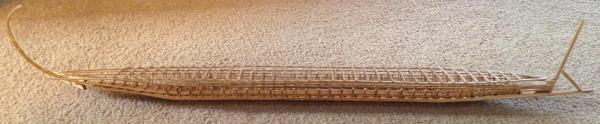


-
Thanks Pat. I've made a lot of progress since the last update; I'll try to post a few pictures tomorrow. 27 days to go!
-
Nice job on the ram! The texture of the paperboard really gives the impression of cast bronze. What type/brand of paint did you use? I've pretty much given up on trying to make the ram for my build out of actual bronze, so I'm looking for alternatives.
-
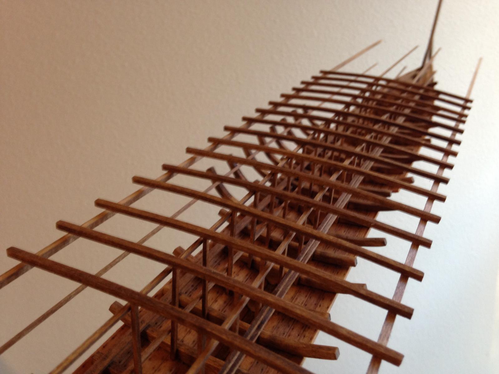
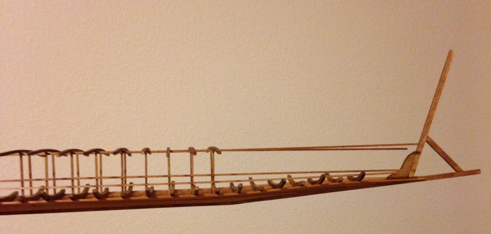
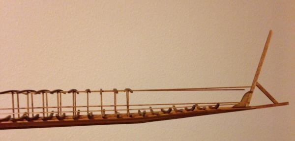
Well, that didn't happen. Anyways, I did manage to get some work done over the past few days. Most of the main deck beams have been installed, and the fore deck beams have been bent and stained. Also, eight of the mid-ribs have been installed. (EDIT: for some reason, the lower deck beam supports/stringers appear to curve rather severely inward, but I just checked the model and they are in fact straight.) (I noticed the stray blob of glue on the deck beam after I took the picture. It has since been scraped off.) The inside of the hull is already getting pretty crowded. I'm going to have to install the rowing benched and footrests with tweezers through the lower deck beams. It still looks somewhat orderly from straight on, but from an angle the effect is much more chaotic. Once all of the hull stringers, benches, and supports are in place it'll be really messy. I can't say for sure when the next update will be, but it probably won't be too long, as the pace is about to increase considerably. I need to have the model finished in 48 days. It's a bit of a rush, but I think I can make it. Thanks for looking!


-
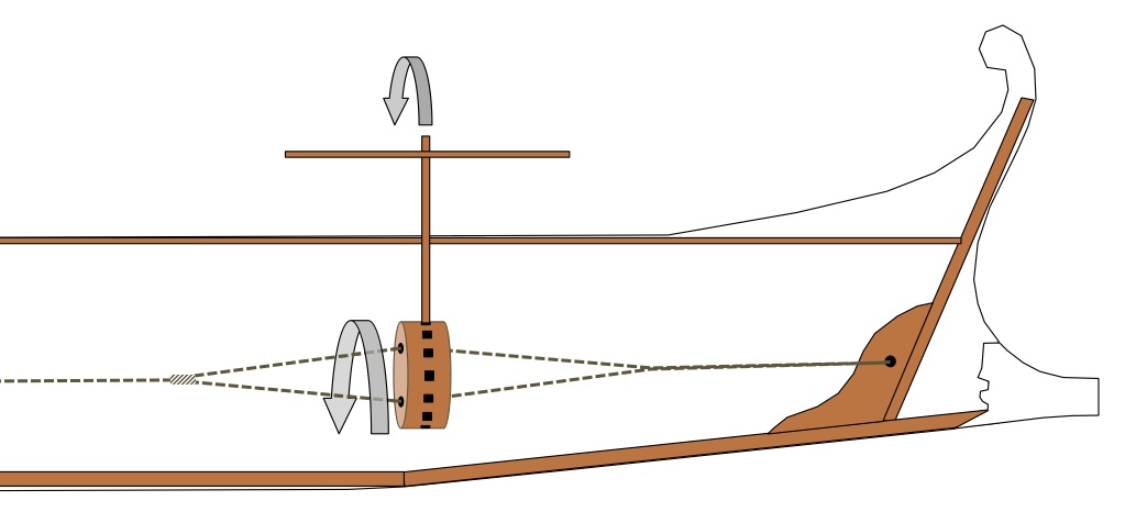
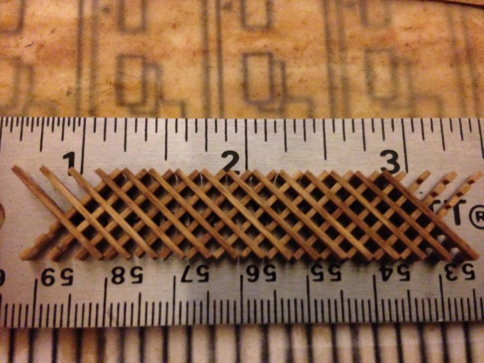
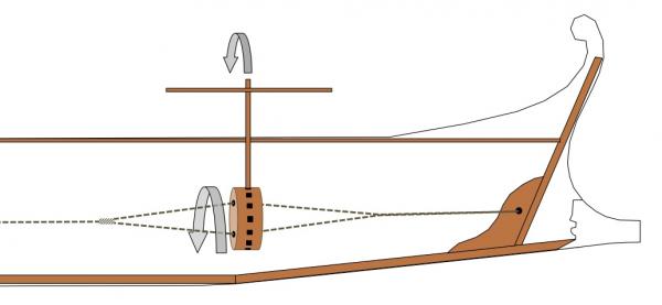
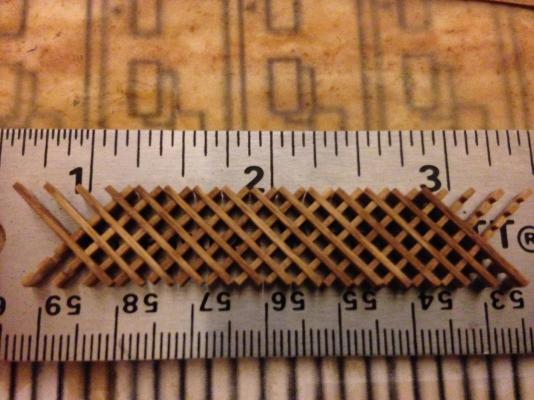
Thanks David and John! I'm glad to see this much interest in such an obscure type of ship. Hans, I agree. Having though about it a little, there's no way they could get that much tension just by pulling on a deadeye lanyard. Wetting the rope is an interesting idea. It certainly seems like it should work, and they may very well have done that in addition to twisting the rope. I put together a quick "sketch" of an arrangement that seems feasible. *Not to scale It's very similar to a Spanish windlass, but borrows the removable poles from Roman torsion catapults. There would have to be an open slot running left to right across the deck, but it could be covered with a removable plank. The crossbeam on the pole allows more people to push on it at once, and the pole/crossbeam assemblies would be disassembled and stored in a rack below deck. (This is how it will be displayed on the model, unless I come across a better idea.) Once the hypozomata was fully tensioned, the wooden cylinder would be held in place with a short pole braced agains the keel, just like a Spanish windlass. As far as the actual model, I've made a little more progress. Six of the middle rib sections have been cut (I cut them on a scroll saw in stacks of 6 or 8 to save time), and three have been sanded, stained and installed. Another 8 lower deck beams have been formed and stained, but haven't had the supports added yet. I'll try to post a photo in a day or so when I get them installed. I've also started working on the grating that goes along the sides, which provides both ventilation and protection from arrows. The problem is that there will be a total of about 48 inches (1220mm) of grating on the ship, which means 720 pieces. I'm using Constructo 45mm bottom boards, with each board cut into two pieces with six slots each. There are 15 pieces per inch, and so far I've made about 2 inches… 690 more pieces is a long way to go.
-
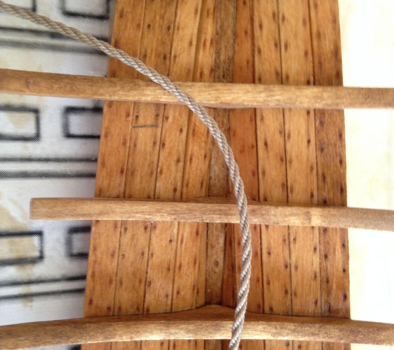
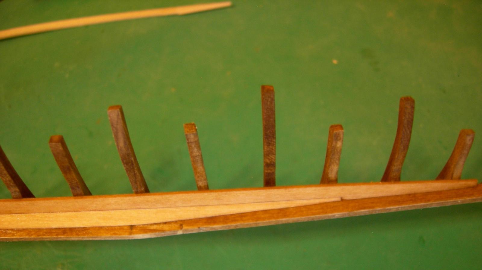
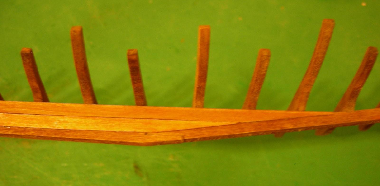
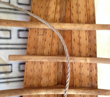
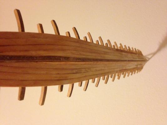
Thank you for the kind words Patrick! I really appreciate the positive feedback. I've finally reached a significant milestone in the planking: (Don't worry, the rather embarrassing gaps between the first strakes and the keel will be filled when the bottom is smoothed out and painted.) This is the last continuous row of planking on the starboard side (on the bottom at least). The subsequent rows will have a gap in the middle, which will be about 40-50% of the length of the ship at its widest point. This row of planking is also the last one that attaches to the short ends of the floors, which means it's time to brush up my scroll saw skills to cut the 60+ middle rib segments. The rope that will be used for the hypozomata was completed a couple days ago. It's made from three ropes, each made from three strands of heavy quilting thread. I haven't quite made up my mind regarding the hypozomata mounting and tensioning gear, but right now I'm leaning towards using deadeyes, based on the J. F. Coates lecture discussed earlier in the thread. "How the hypozomata were tensioned remains a mystery. In the Egyptian ships the hogging trusses were plainly tensioned by twisting them together, making what is often called a Spanish Windlass. That is not a very efficient mechanism because in twisting the ropes they are bent into helices, so that bending stresses are generated which are about as great as the direct tension which is desired. However, it is clear enough that that was what the Egyptians did. In latter day sailing ships standing rigging was invariably set up by three-fold purchases in which the blocks were without sheaves but greased. They are called deadeyes. I think that method is more likely to have been used in triremes also." I'm still not sure how they could possibly have tensioned a rope to 13.5 tones using deadeyes. They must have had a lot of people pulling on the lanyard. I guess it's conceivable that they might have used a team of oxen or something, but that seems unlikely, as the hypozomata were often replaced during a campaign. Any ideas? If I decide not to use deadeyes, the next best alternative would be a sort of ratcheted windlass, which is the only other mechanism I can think of that would tension the rope without twisting it. Thanks for looking!

-
Slow? You've practically finished your entire model in the same amount of time it took me to do about 1/3rd of the framing on my build! I like the ornaments-- they look very period-appropriate. What kinds of coins did you make them out of?
-
CA adhesive, which one do you use?
Sharpie replied to Modeler12's topic in Masting, rigging and sails
I also prefer the Loctite. Unfortunately the dispenser bottle isn't very well designed, but if you pull the blue part out the bottom with a pair of pliers, you can squeeze the tube itself, and get at least 10-15% more glue out of it. For thin CA, I use this stuff: I prefer using small tubes like this because it makes it less likely that the bottle will get hopelessly clogged up while there's still a lot of glue left. -
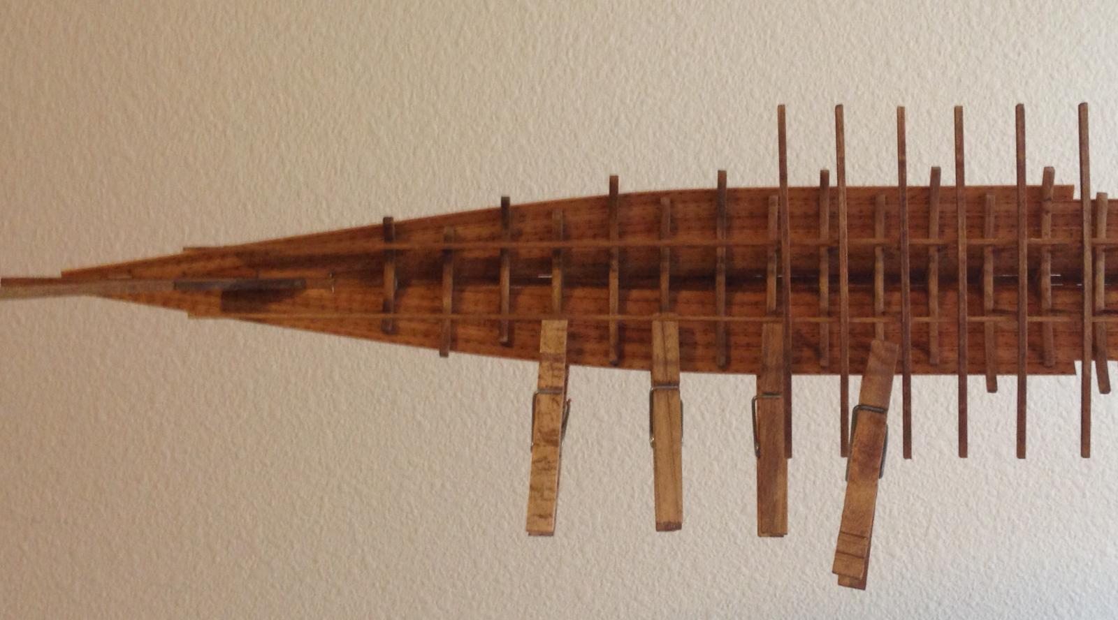
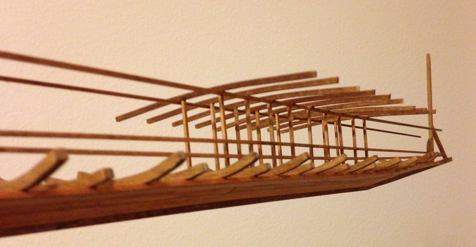
Thanks guys! The latest progress is a little more visually impressive; I've added the first 9 lower deck beam/support assemblies, as well as the rowing bench and footrest supports on the starboard side. This gives a much better impression of what the size and shape of the finished hull will be.
-
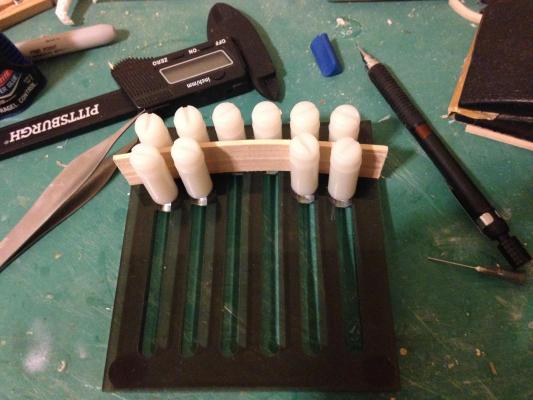
More progress! The photo's a little fuzzy, but it gives a good idea of the current state of the build. Here's a slightly early photo from a different perspective. I had previously been thinking of covering the hull below the waterline with lead sheathing, as was done on some merchant ships, but Michael Pitassi's Roman Warships points out that this would have been too heavy for a war galley. Instead, the lower portion of the hull will be painted black, to simulate the timbers being coated with pitch. I also cut the 48 central lower deck beam supports. I'll wait to cut the fore and aft lower deck beam supports until I'm ready to install them, so I don't have to worry about keeping each set labelled and sorted. I got a package from MicroMark today with a plank forming jig, which is being used to form the central lower deck beams. It sure does make things easier to be able to fabricate 10 identical pieces at a time! Finally, I accidentally broke off the sternmost part of the keel. Fortunately, it broke cleanly along the joint, so it will be an easy fix. Thanks for looking!

-
Thanks Steven! Other (non-ship related) projects notwithstanding, I haven't accomplished much over the past week, but I was able to pick up the pace a bit today. Here's an overall shot of where I am with the planking. The perspective is a bit weird, since the photo uploader insists on rotating it. A better close-up of the stern: I'll be adding a few more planks later today-- the rest of the third row and half of the fourth has been cut, bent, detailed and stained, and I'll glue them on as soon as they're fully dry. It may be a while until the next update, since I have a lot of fairly monotonous planking to do. Thanks for looking!


-
Thank guys! Pat, I thought about trying to find one harder wood, but my local hobby shop only has basswood, and I couldn't justify placing n online order for a 0.75 x 10mm pice of wood. I probably will use a metal pin when I get around to fixing it. It won't be very visible, so I could just oxidize the metal in the stove flame to darken it, and it will look fine. I'll try to post an update on the planking in the next couple of days-- I'm almost to 3 rows on each side.
-
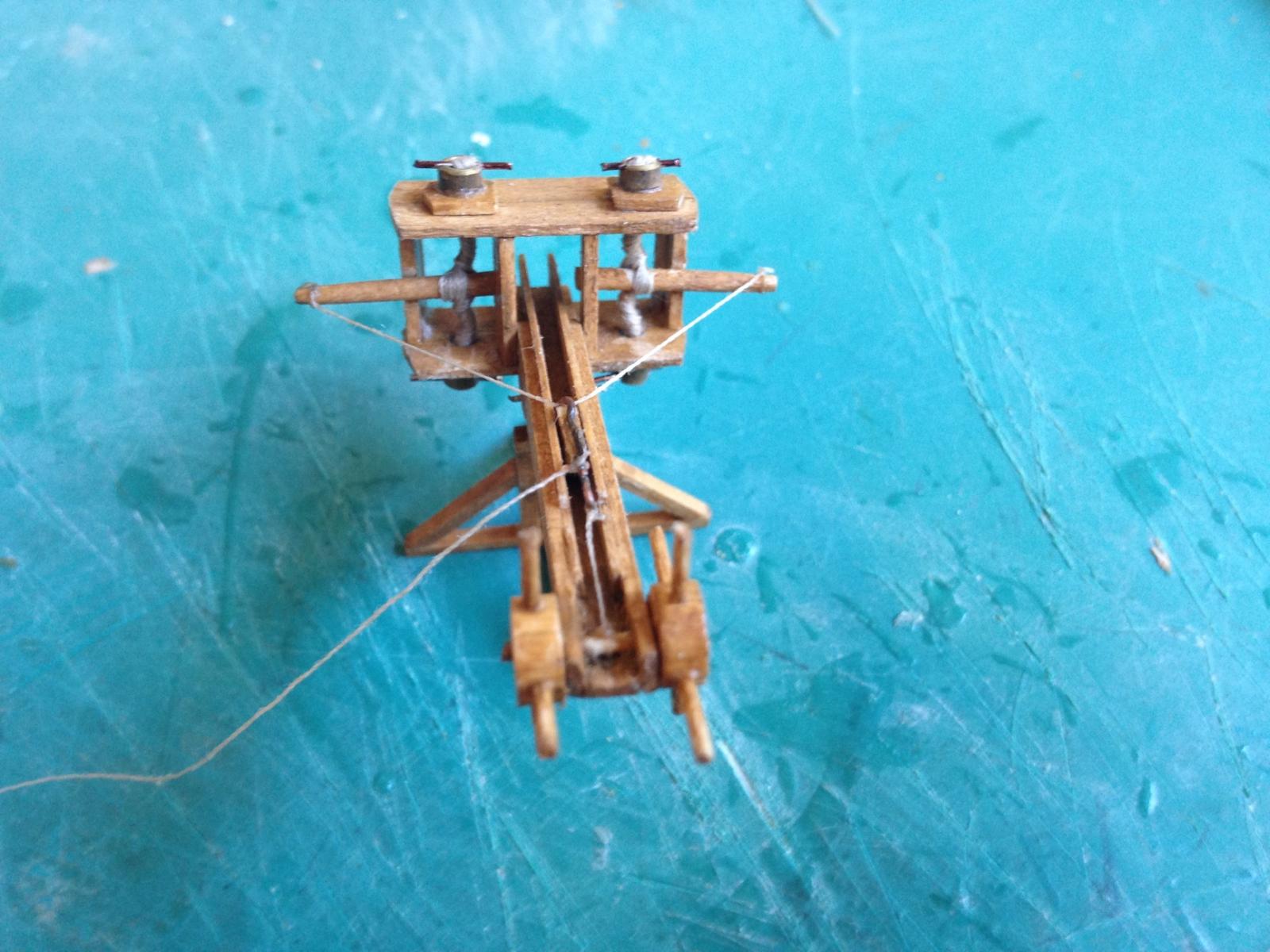
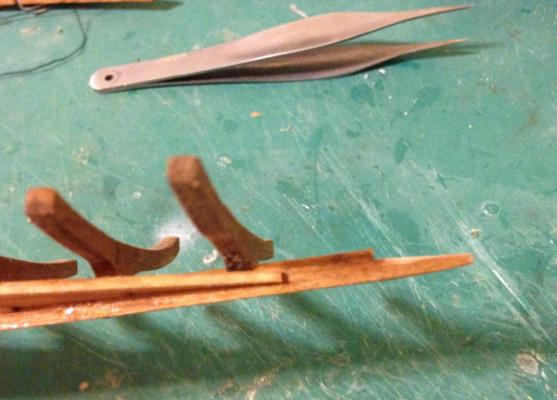
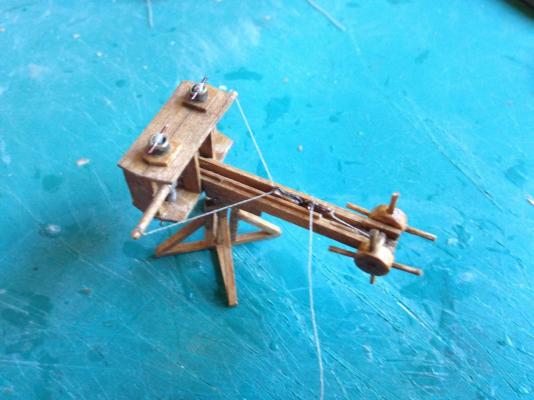
The woefully slow progression of planking continues off-camera, but in the meantime, I finally finished the ballista! (Well, sort of-- see the bottom of the post.) I had to make the arms a bit thicker than I had planned, since the torsion skeins are very tight. I managed to get the winch and trigger mechanisms to work, but I had to get a little creative (i.e., inaccurate) on the trigger. I figured it was worth sacrificing a little bit of accuracy in return for functionality. However, I was unable to successfully test fire the ballista, since the winch dowel that the string winds around broke under tension, and the articulated elevation adjustment joint came apart. I'll try to fix this by replacing the elevation joint with a slightly thicker piece of wood, and soaking the replacement winch dowel in CA glue to strengthen it. Once I get it all back together, I'll try to take a video of it firing, but no guarantees.

-
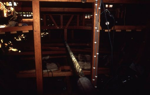
Here's a photo of the Olympias' hypozomata-- it seems to be just above the lowest level of benches.
-
Thanks Hans. This is similar to what I had in mind, except I was thinking of using a rat tail file. Staining the inside edges of the holes will be a pain; I can see there are definitely advantages to using real oak!
-
A little more progress today. So far, I've installed two rows of planking on both sides, and I'm in the process of cutting/bending the third row. Bow planking: Stern planking: The fit of the planks is pretty good, but not perfect. However, this part of the planking will be covered on the exterior by lead sheathing, so minor gaps caused by the bevel being slightly off aren't really a concern as long as they aren't visible from the inside. This is the first plank I've had to bend prior to fitting it onto the ship. I just immersed in hot water for about 30 seconds and clamped it to a scrap piece of 2x4 with the desired curve. It seems to have held the curve well, even though I've read that basswood has poor steam-bending properties compared to other wood. I also started work on the ram, but I may end up throwing it out. The problem is that the phosphor bronze sheet only comes in one thickness (0.008" or 0.2mm), and I can't seem to do a decent job of bending or layering it to create the thickness of the horizontal fins. I'll probably end up using copper instead, since it will look very similar once the patina forms and is available in much thicker sheets or strips. Thanks Pat. Have you read the Hellenic Traders series by H. N. Turtletaub (Harry Turtledove under a pseudonym)? I quite enjoyed the series, as it was full of well-researched details about the ancient Mediterranean, and especially ships, during the time period right after the death of Alexander the Great. Michael Pitassi does address the ventilation problem in Roman Warships, proposing various configurations of large gratings on the deck as well as wooden screens next to the rowing benches that are above the level of the gunwales. But with a dromon, I can see air supply being much more of a problem based on my limited knowledge of them. As far as the Olympias' hypozomata, I don't think they were even able to try using natural materials, since they couldn't find an adequate supply of hemp rope, and no synthetic materials had similar properties. The steel cable wasn't an ideal solution either. Because steel cable isn't very elastic, it would apparently slacken when the ship flexed one way, and snap taut when it flexed the other, leading to concerns about it potentially breaking and injuring the crew. Concerning the plurality of zomata, this excerpt from John F. Coates lecture clears thing up a little: "The second piece of evidence concerning strength was about great ropes, 47 mm or so in diameter, and nearly twice the ship's length. Two were rigged in each ship when on active service, and two more were carried aboard as spares. A decree laid down the number of men required to rig them in a trireme. The inscription about them is unfortunately damaged, but the space occupied by the missing number indicates that it was probably 50. They were important pieces of kit because their export from Athens was a capital offense." Here's a link to the rest of the lecture.

-
Very nice! What tool(s) did you use for boring the holes? I'm pretty nervous about making the oar ports on my current build (when I get that far, that is), since I'm afraid I'll damage the hull in the process.
-
Looking great! I wish I had seen this a couple of years ago; the structure for mounting the seats is so much more sensible than what I came up with for my trireme. I quite agree with this. While I do admire the skill that goes into constructing a model on which every piece of wood is perfectly smooth, I can't help but feel that this would be somewhat unrealistic for a ship constructed entirely with iron saws and hand axes. Not to say that the classical civilizations were incapable of producing a smooth piece of wood, it just seems unlikely that every plank on a 37-meter warship would have been planed perfectly flat.
-
Thanks Banyan and Hans! The lack of any surviving ancient Roman/Greek vessels is one of the reasons why I like building them-- it leaves a lot more from for personal preference and aesthetics than a well-documented ship like the Victory. Hans, the pump mechanism was in this thread. You're probably right about it being a bilge pump, not an air pump, since the rowing compartment is designed with screens to provide ventilation as well as protect the rowers from arrows and such. I suppose it might also have come in handy in dealing with smaller leaks when the hull sustained damage in battle. I'm following your trireme build log with interest. Really looking forward to seeing all the oars at that scale!
-
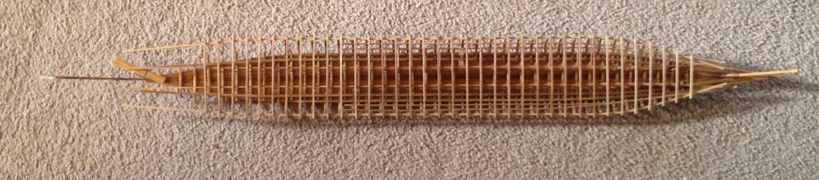
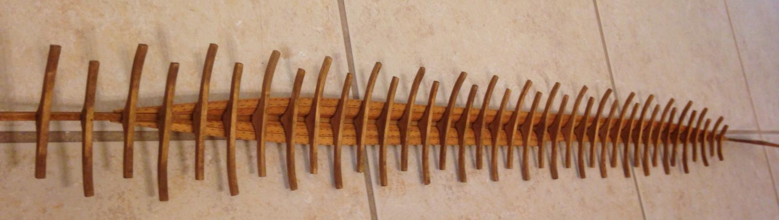
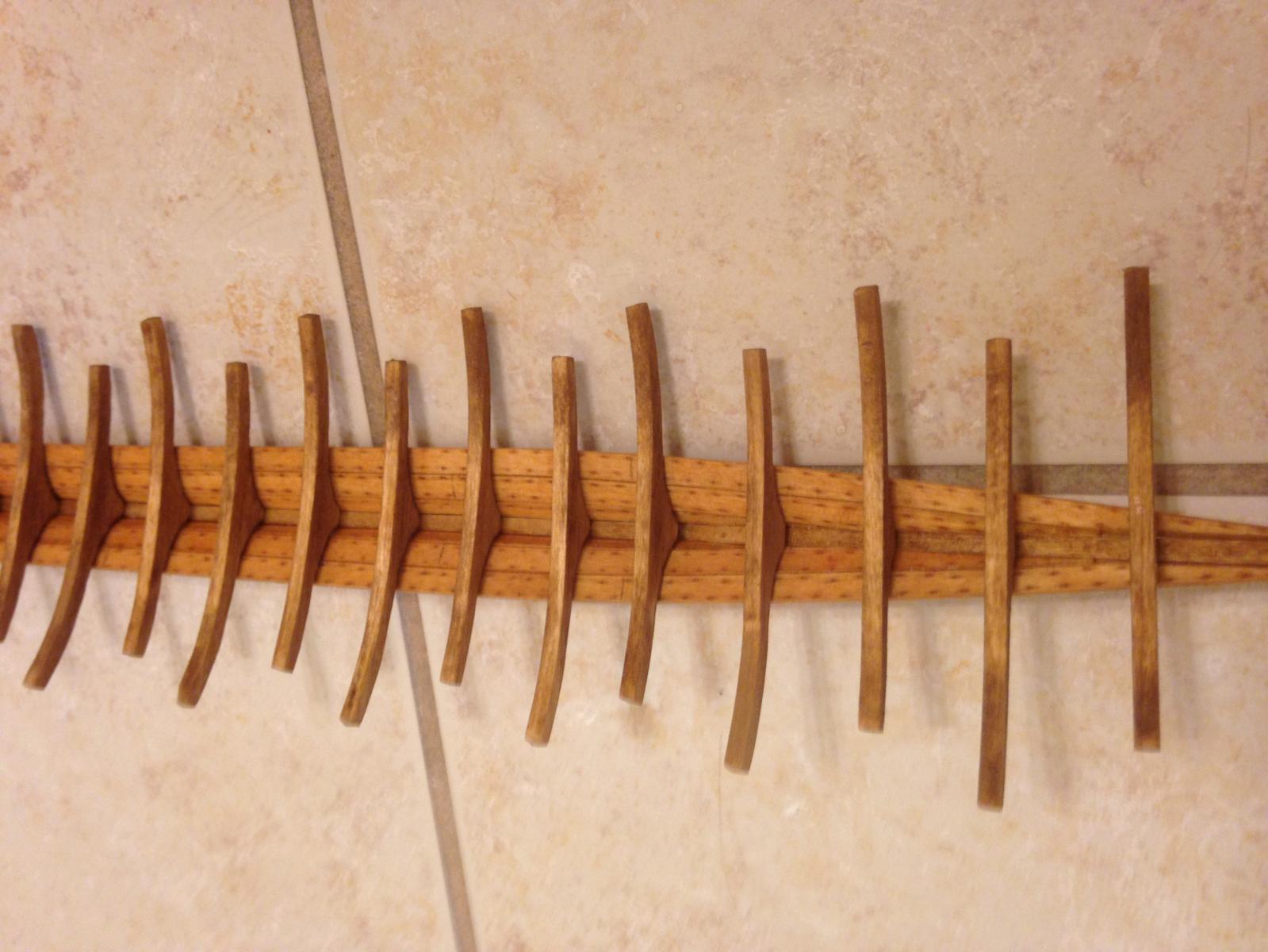
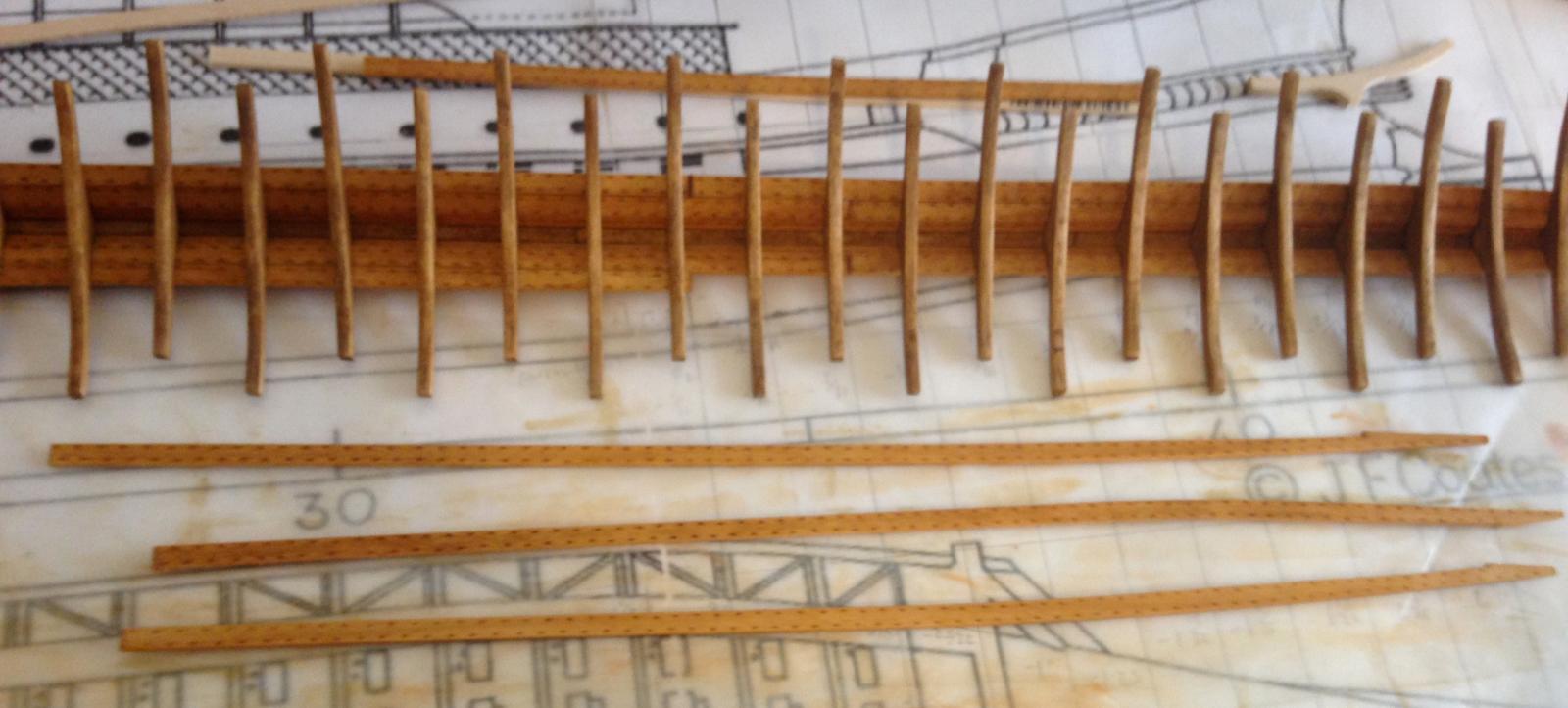
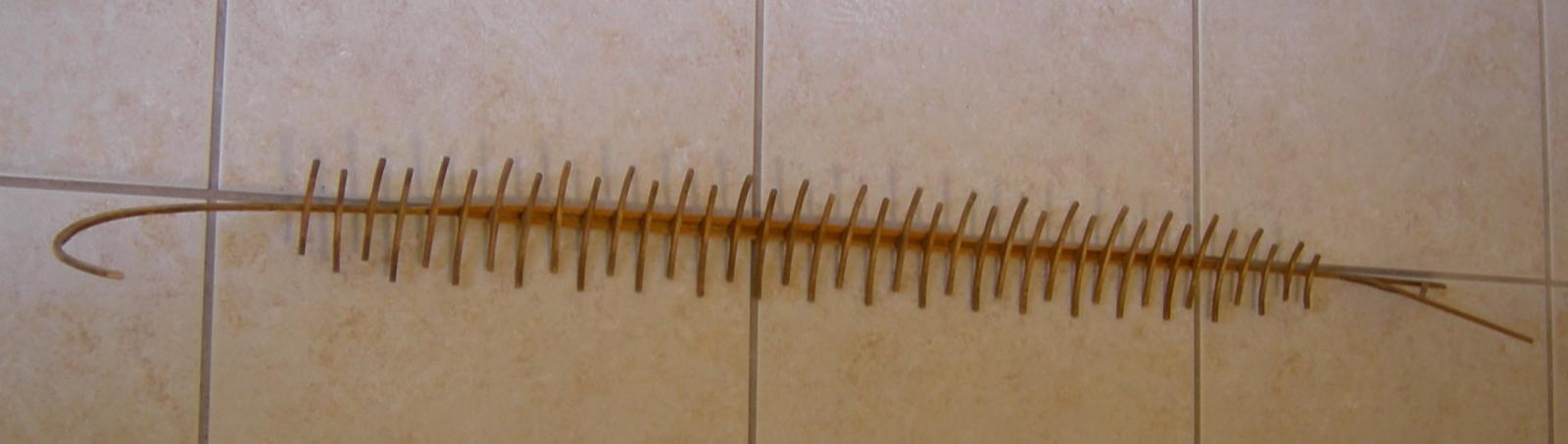
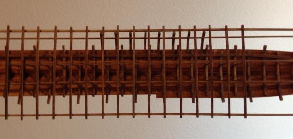
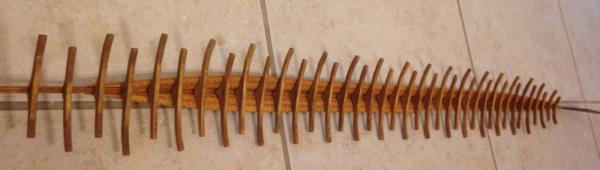
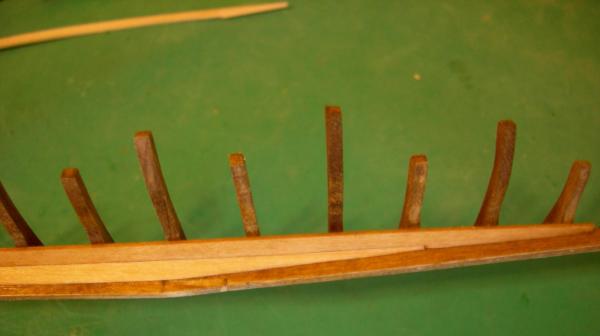
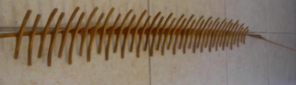
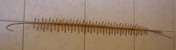
Despite all appearances, I have not abandoned this build! I've only been able to work on it on and off, a few minutes at a time, so I haven't made a whole lot of progress. (This is largely due to having started construction on a recreational hovercraft, which gets priority because of its much larger budget.) In the 58 days since my last post, I've cut 4 more floors and treenailed them to the keel, sanded, stained and sealed all of the floors cut so far, and cut, detailed, beveled, and attached a grand total of 2 1/2 planks. Given how much time it takes to press the treenailing details into the planks, I'm very glad that this will not be a fully-planked model. Here's what it looks like now: (Sorry about the picture quality. I'm using an ancient 5MP Nikon, but I'll be getting a better camera soon.) A few of the floors aren't quite straight, but most of them still haven't been glued in place. The planks are glued at the edge and to the few floors that are permanently affixed; the rest of the floors will be glued in place using the first couple of planks on each side as a guide to ensure that they all line up properly. Hopefully the next update will follow a little sooner than this one did. Thanks for looking!
-
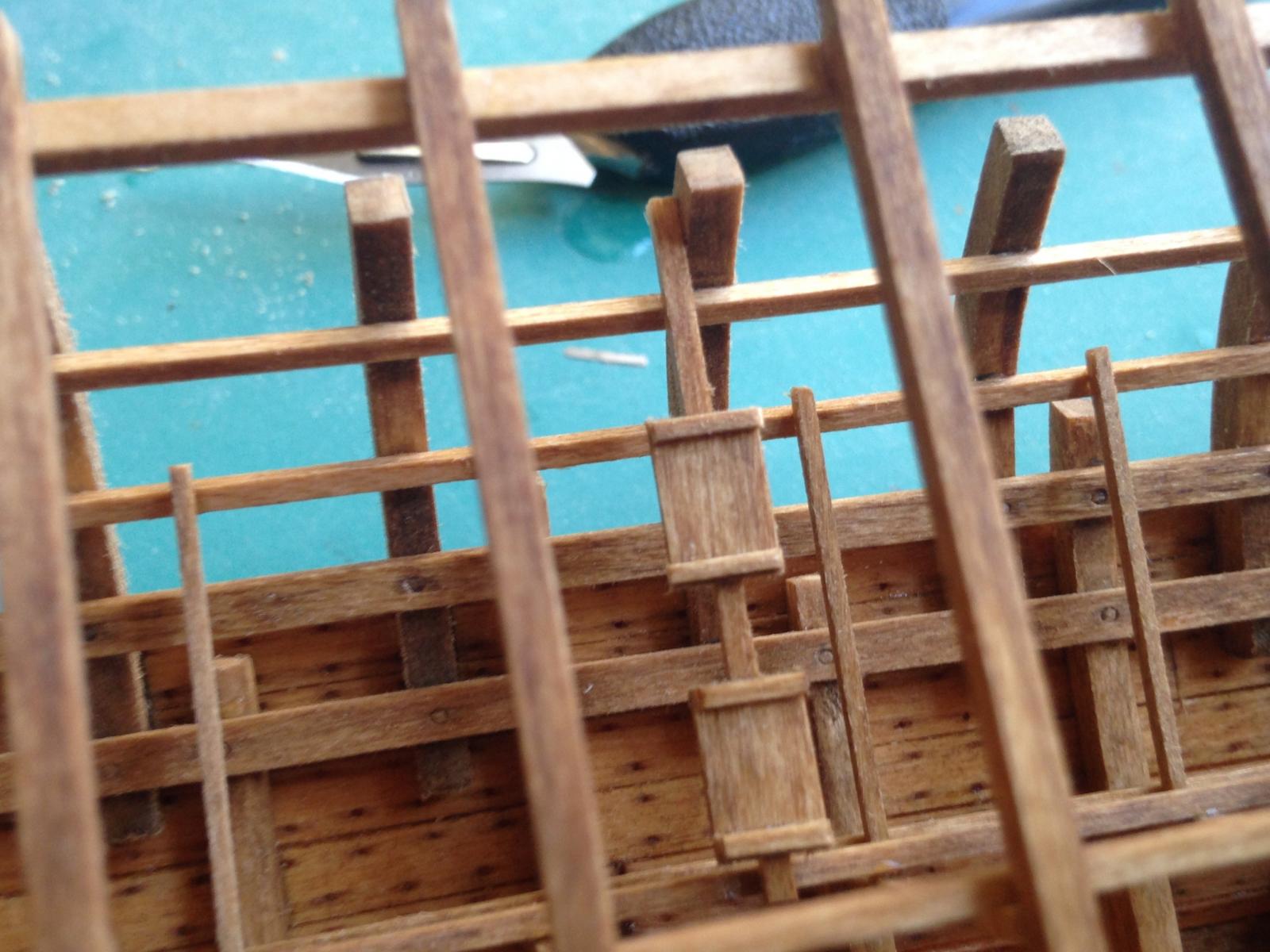
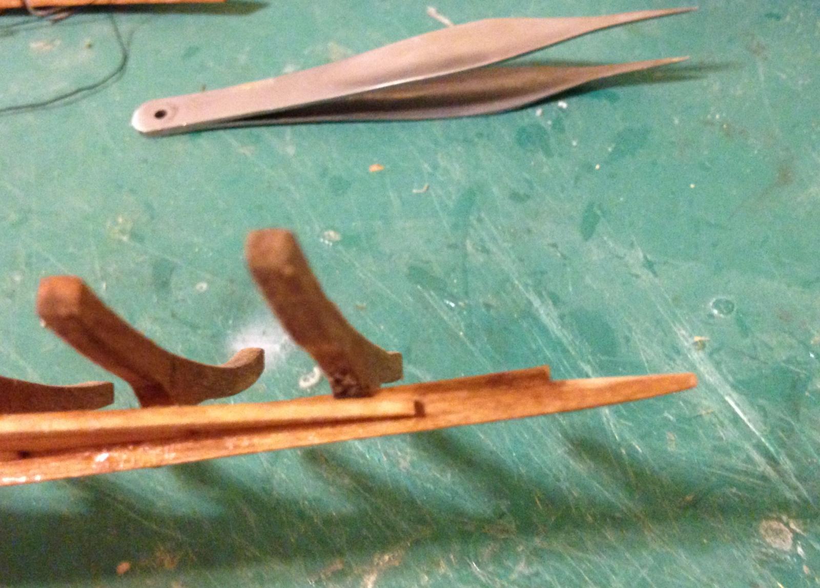
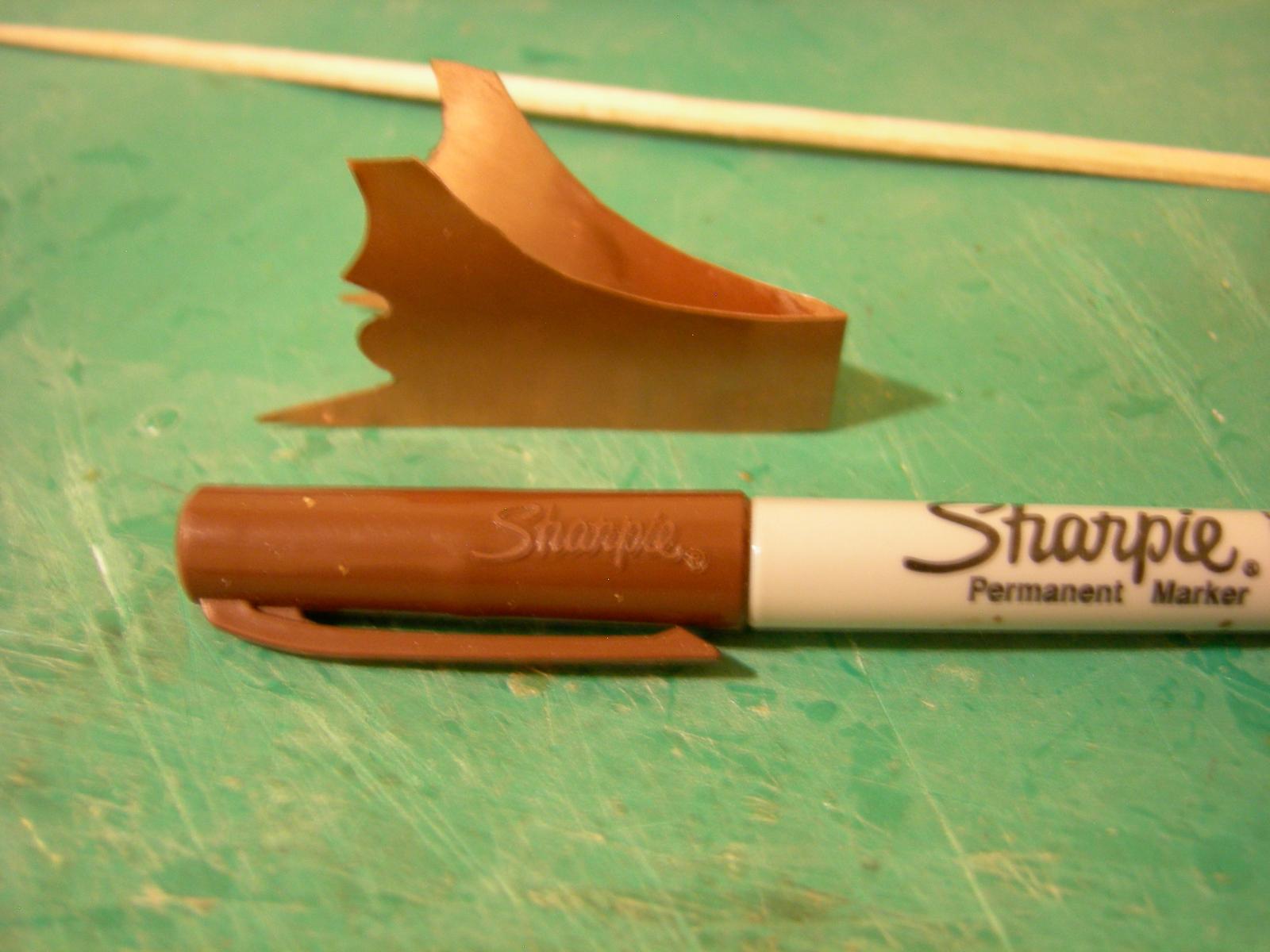
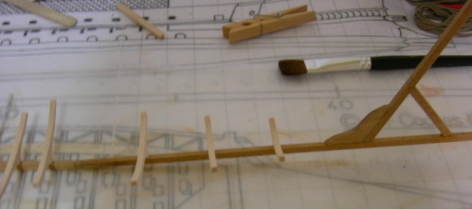
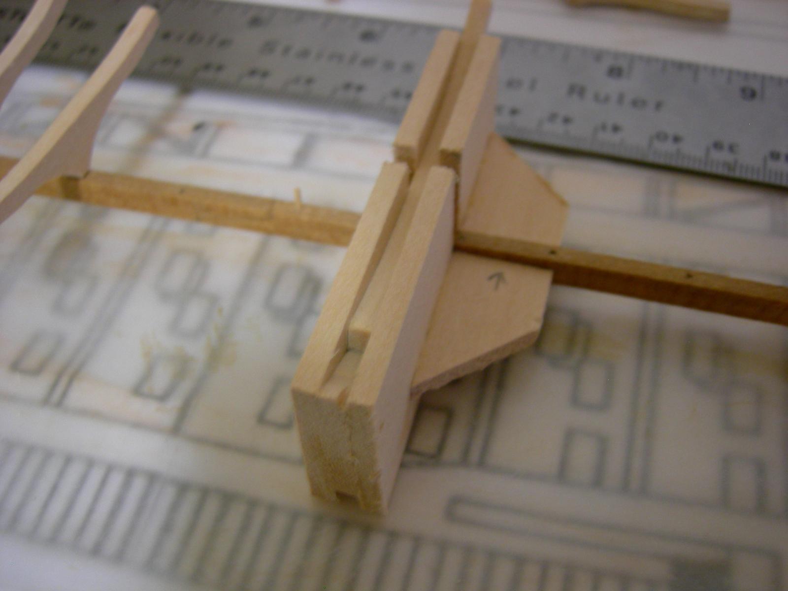
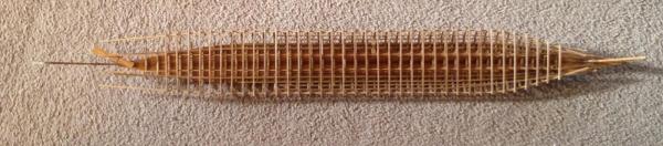
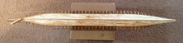
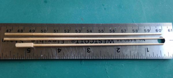
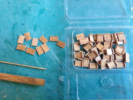
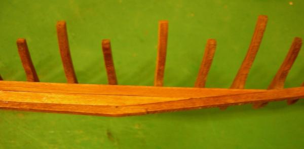
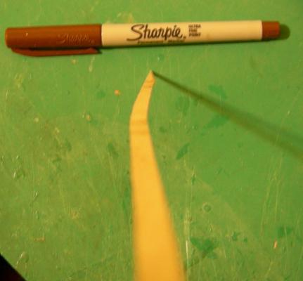
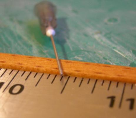
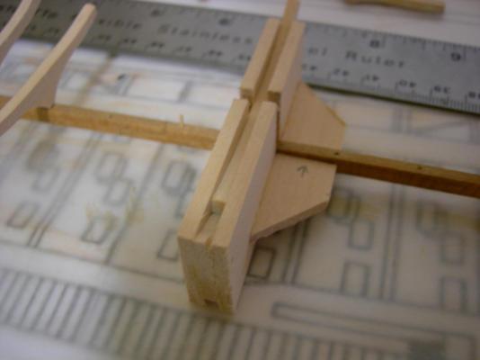
Well it looks like this build log is going to be a little more intermittent than I had originally planned. Anyway, I finally got some time to get back to work on this today. I intended to cut seven of the front floors, but my scroll saw skills have declined considerably, so I only ended up with three usable pieces, until I retrace the templates and try again. But at least the three floors that I ended up with are spread out, so they give a good indication of the shape of the prow. I also prepared one plank with the mortise and tenon joint dowel detailing. Since the lower planks will be covered with lead on the outside, the detailing only needs to be applied to the insides. Based on the amount of time it took to prepare a single plank, I don't think it will take an unreasonable amount of time to apply this detail to the entire model. The modified hypodermic needle used (22 Ga.): The photo makes the detail look a little more distinct than it really is; I don't think it will make my ship look like it has measles. And, finally, I've started attaching the floors to the keel. I put together a simple jig to ensure that the floors are properly aligned, but unfortunately I have to let the glue fully set before I can remove the jig and move on to the next floor. This is going to be a long process.


-
That does seem likely, especially given its similarity to the torsion skeins on Roman artillery. I've only skimmed it so far, but this lecture by John Coates mentions that Egyptian ships used a Spanish windlass to tighten their hogging trusses. Although they were looped around the prow and stern of the ship, instead of being a single straight tendon running parallel to the keel, it seems very probable that the Romans would have used a similar method of tensioning the ropes. However, it seems to me that this could impart a considerably amount of torsion to the ship. I guess that minimal leverage resulting from the small size of the hypozomata's attachment point would prevent that?
-
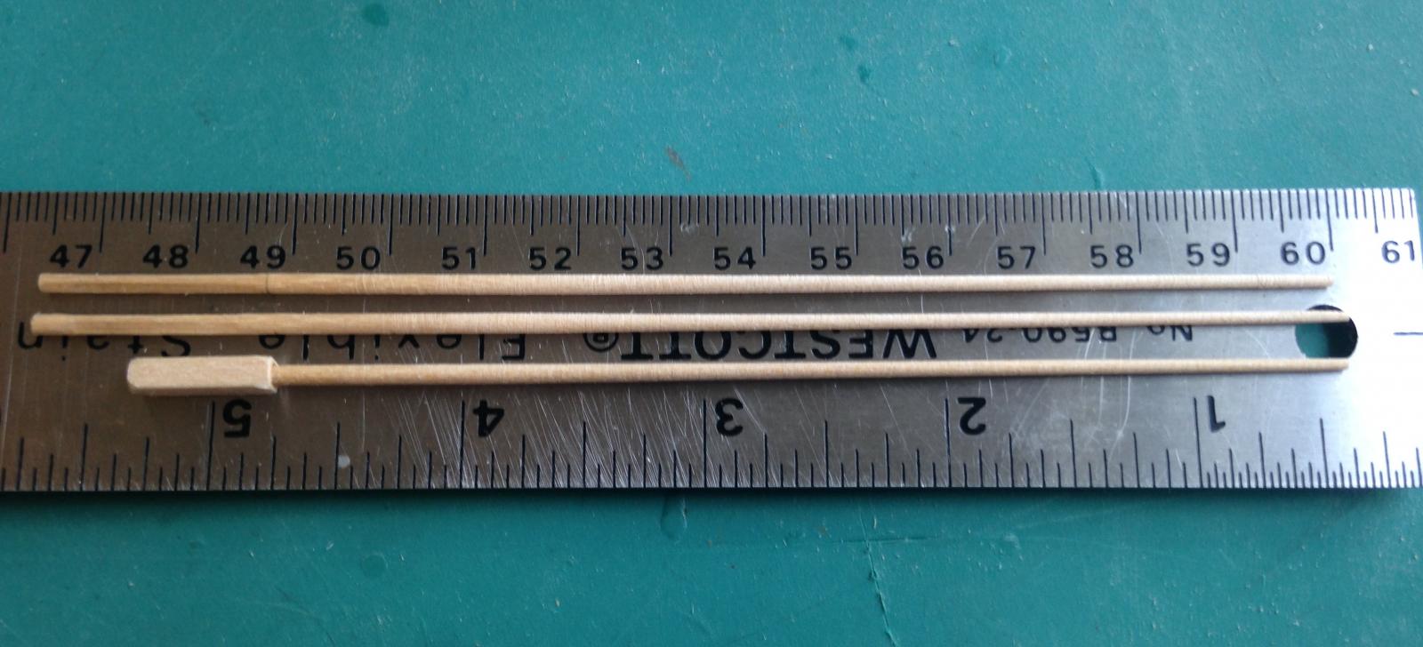
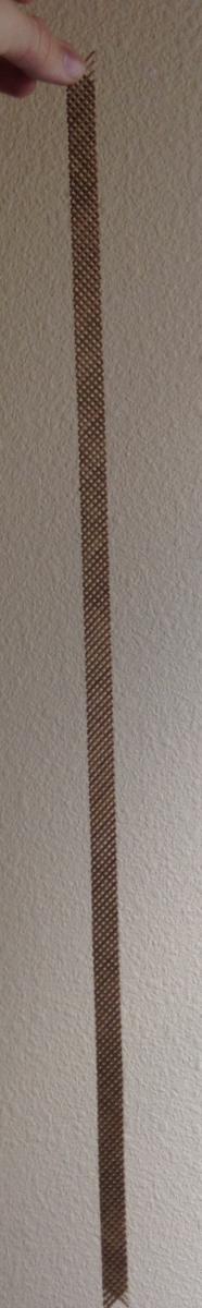
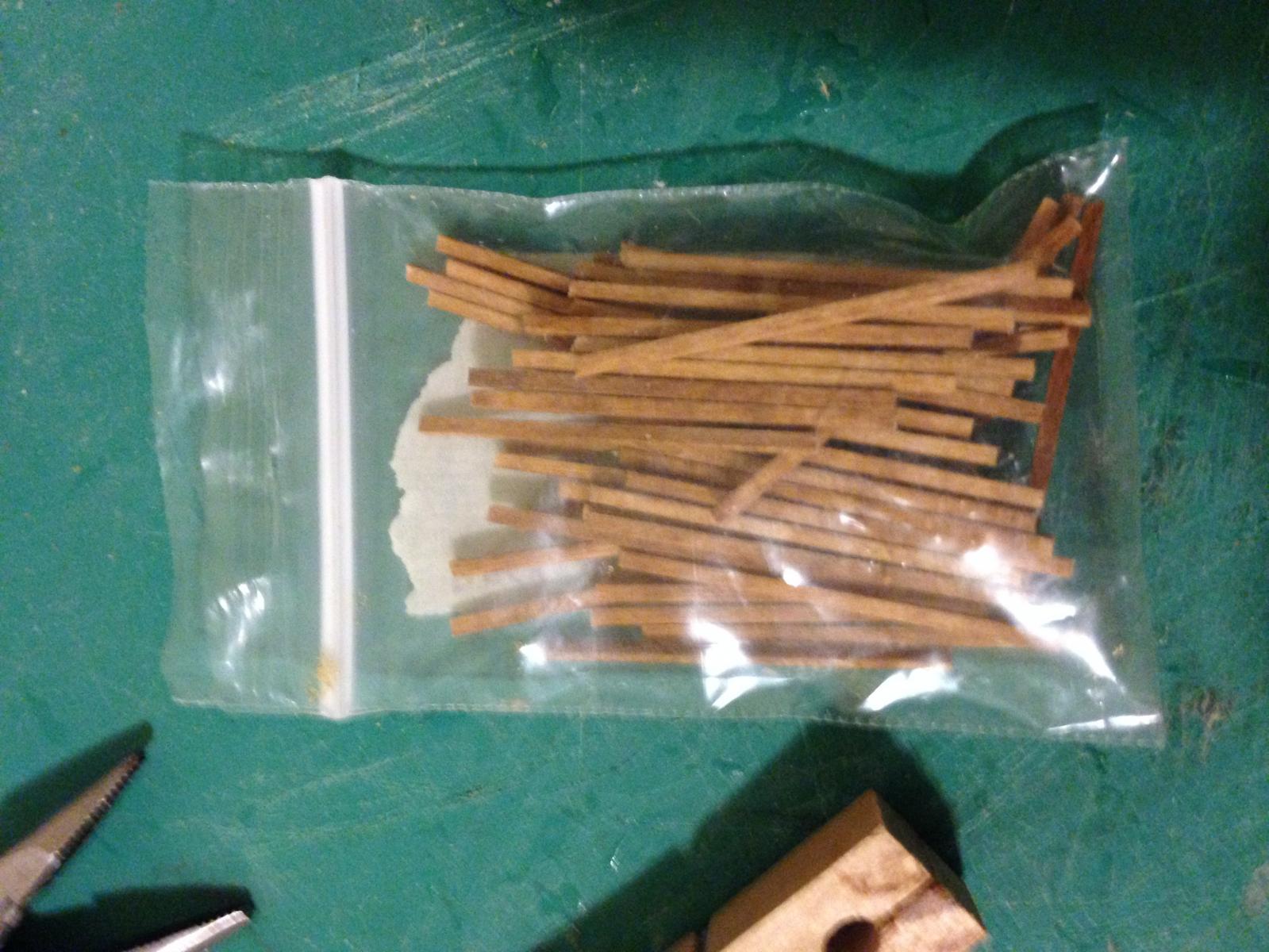
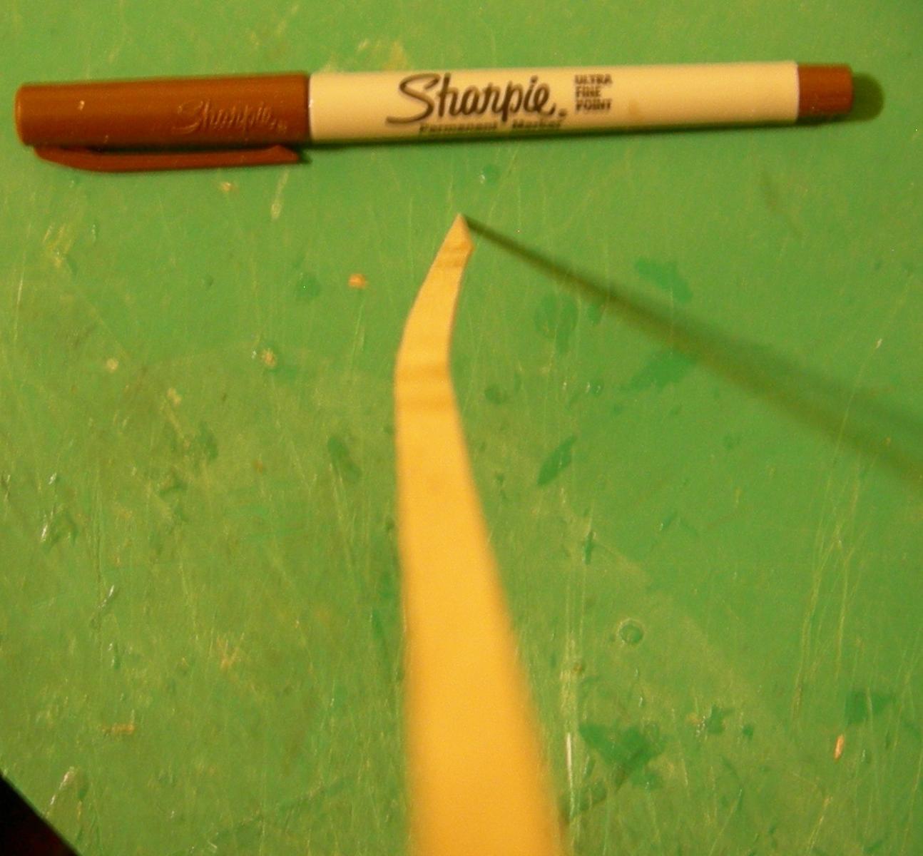
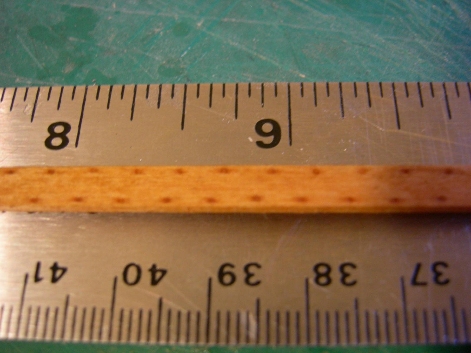
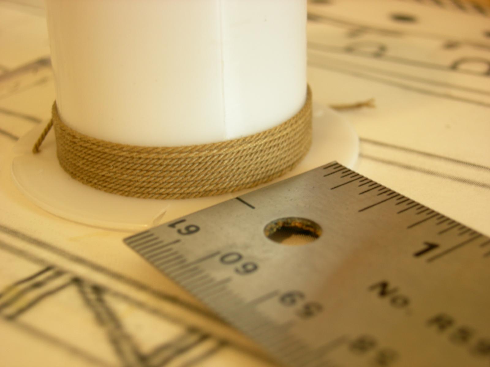
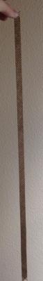
I seem to have a motivational problem when it comes to measuring/cutting frames. So, I spent some time today working on making rope. I did some experimentation with this a while ago, but this is the first usable piece of rope I've turned out. I used quilting thread, which is quite a bit thicker than regular sewing thread, so my three-strand rope has a diameter of about 0.8mm. It's not completely perfect, but then again my ropewalk is made of scrap wood and paper clips. I plan on using three ropes like this one to make the hypozomata, the highly tensioned cable that runs through the ship near the keel. The hypozomata prevented the ship from flexing during rough seas or ramming, and was essential in maintaining the structural integrity of Greek and Roman warships. In a trireme, the hypozomata is written to have been about 47mm in diameter, and tensioned to 13.5 tones of force. Presumably the hypozomata in a quadrireme would have to have been slightly larger, so it looks like my rope diameter is ideal for this. Unfortunately, there is no recording of how the hypozomata was tensioned, so when I come to that point in the construction, I shall merely attempt to contrive some sort of windlass-ish thing that looks likely.


-
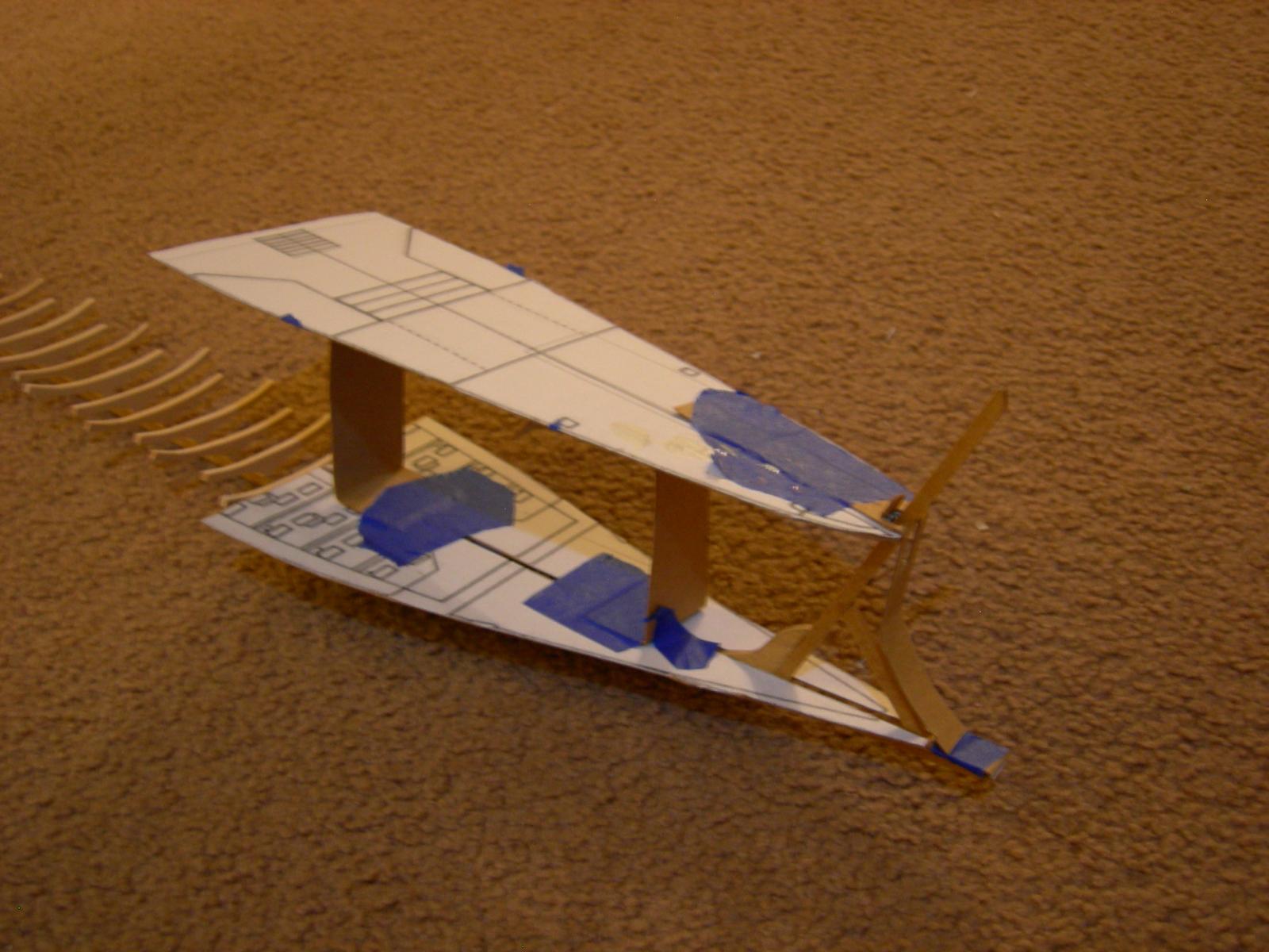
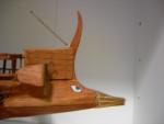
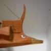
OK, so I made a crude mock-up of the prow using the mirrored profiles in my previous post, set at the proper height as determined by measuring the plans... …and I think my initial assumption was correct. With the profiles in place relative to each other, the proportions look much better. Note that the deck height shown here is the deck height on the plan, which is actually for a quinquereme. The deck height of the model will be considerably lower. I think I failed to mention earlier that I'm actually not strictly following the plan-- the model's hull is slightly narrower than the drawing's, since it would only have to accommodate four rowers in two banks, rather than five rowers in three banks.

-
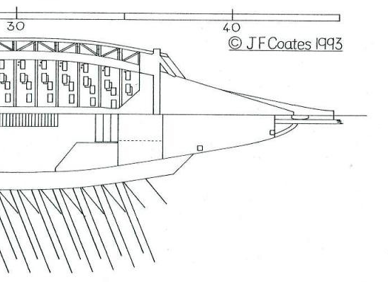
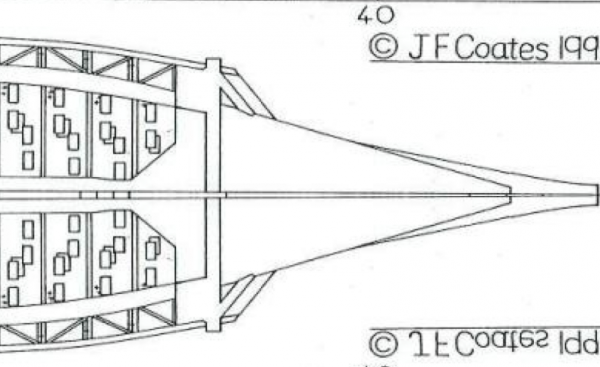
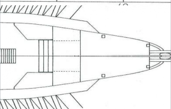
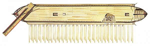
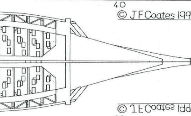
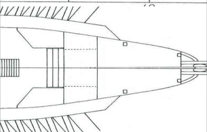
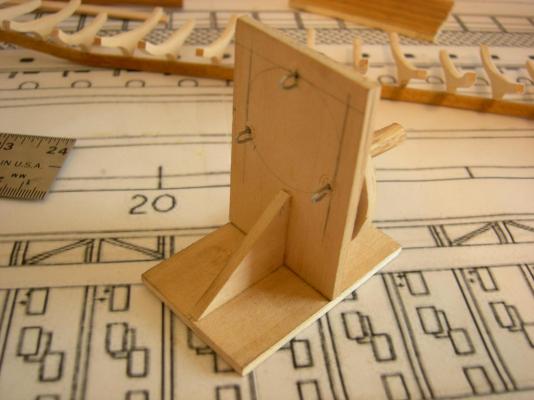
I seem to have run into a minor obstacle. I need to take measurements of the prow to make the forward frame templates, but the prow section on the plan is a little confusing. Here's how it appears in the original drawing: Having very limited knowledge of how to properly interpret this drawing, I would assume that the two sides simply show the profile of the prow at different heights. Is the top half at the waterline, and the bottom half at the deck level, or somewhere else? When I mirror the top half, this is what I end up with: This looks far to pointy to me, especially when compared to drawings such as this one: But mirroring the bottom half of the prow on the drawing still doesn't quite look right: How is this drawing supposed to be interpreted? Thanks in advance!