

0Seahorse
-
Posts
107 -
Joined
-
Last visited
Content Type
Profiles
Forums
Gallery
Events
Posts posted by 0Seahorse
-
-
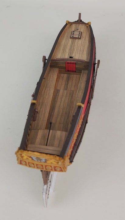
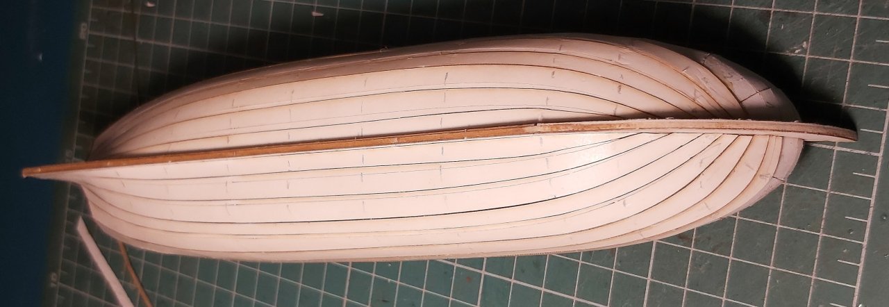
It took a long time to finish the hull, but it can finally be presented.
In accordance with period drawings, I applied thick nails (glue and paint) on the wales, and attached two pairs of reinforcements to the stem.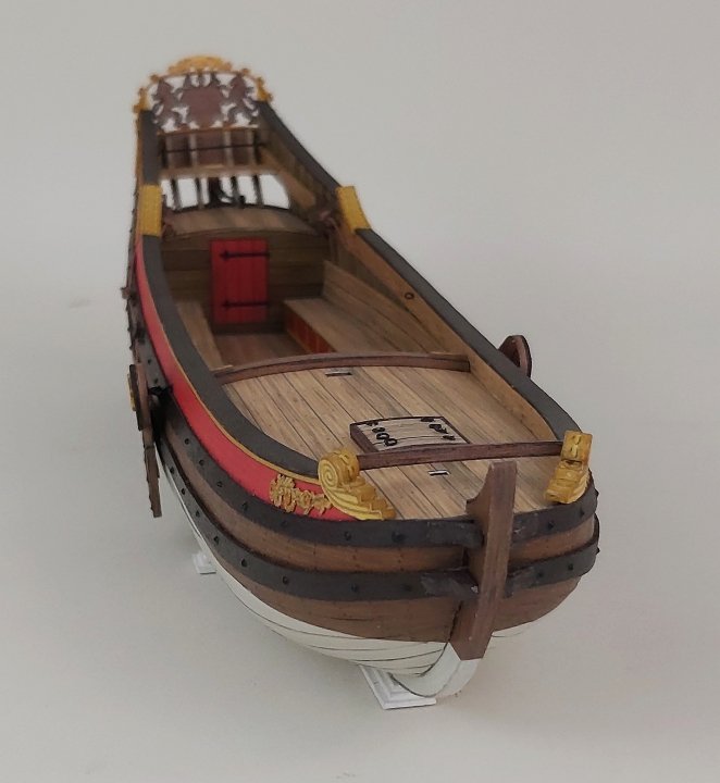
All the finishing touches and modest decorations appeared. Initially, I thought about cutting them with a laser, but it would require some plasticizing (e.g. with glue) and painting - which means a lot of work and time. So I cut out several copies by hand with a sharp scalpel and glued them to the sides. The decorative ends of the railings are simple bottomless "boxes" that I used to mask the ends of the edges of the railing.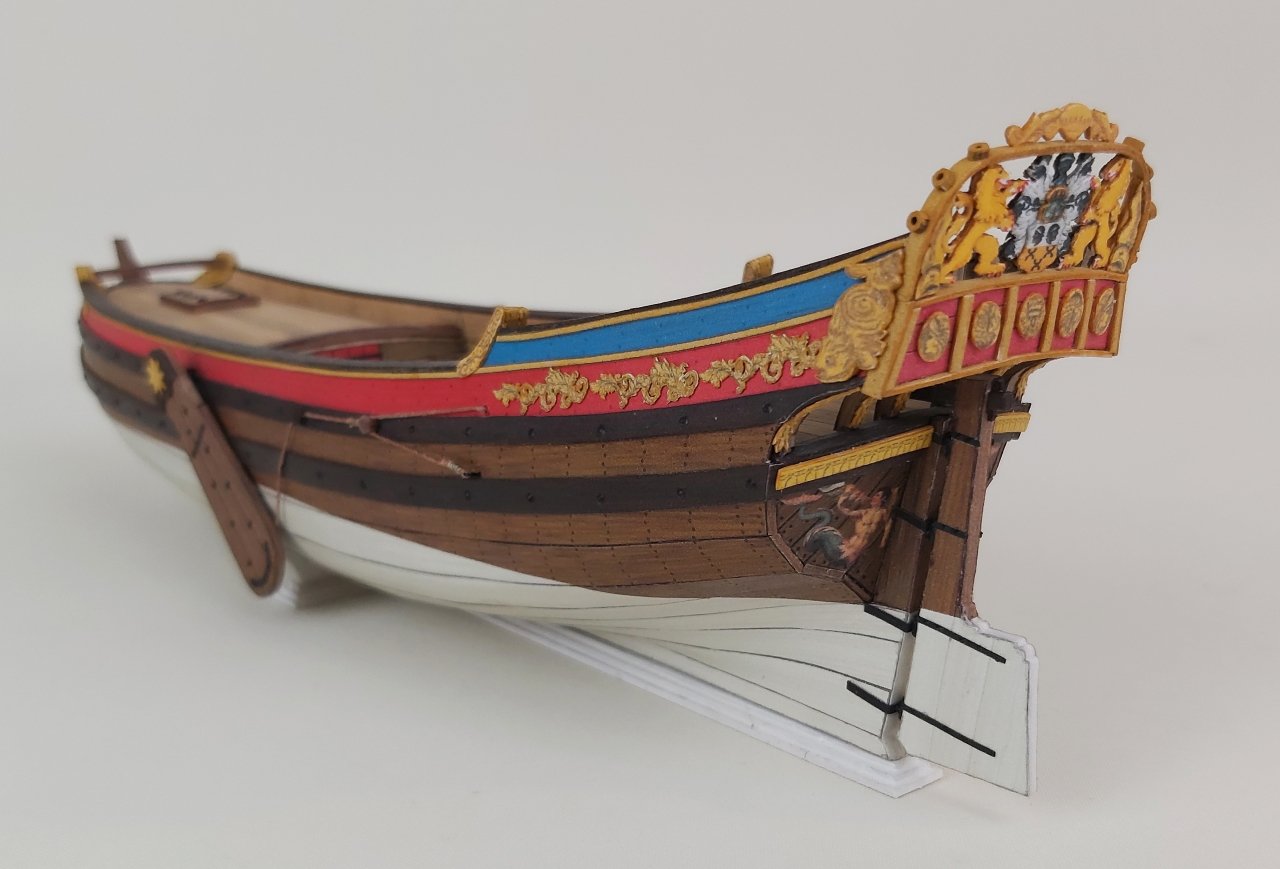
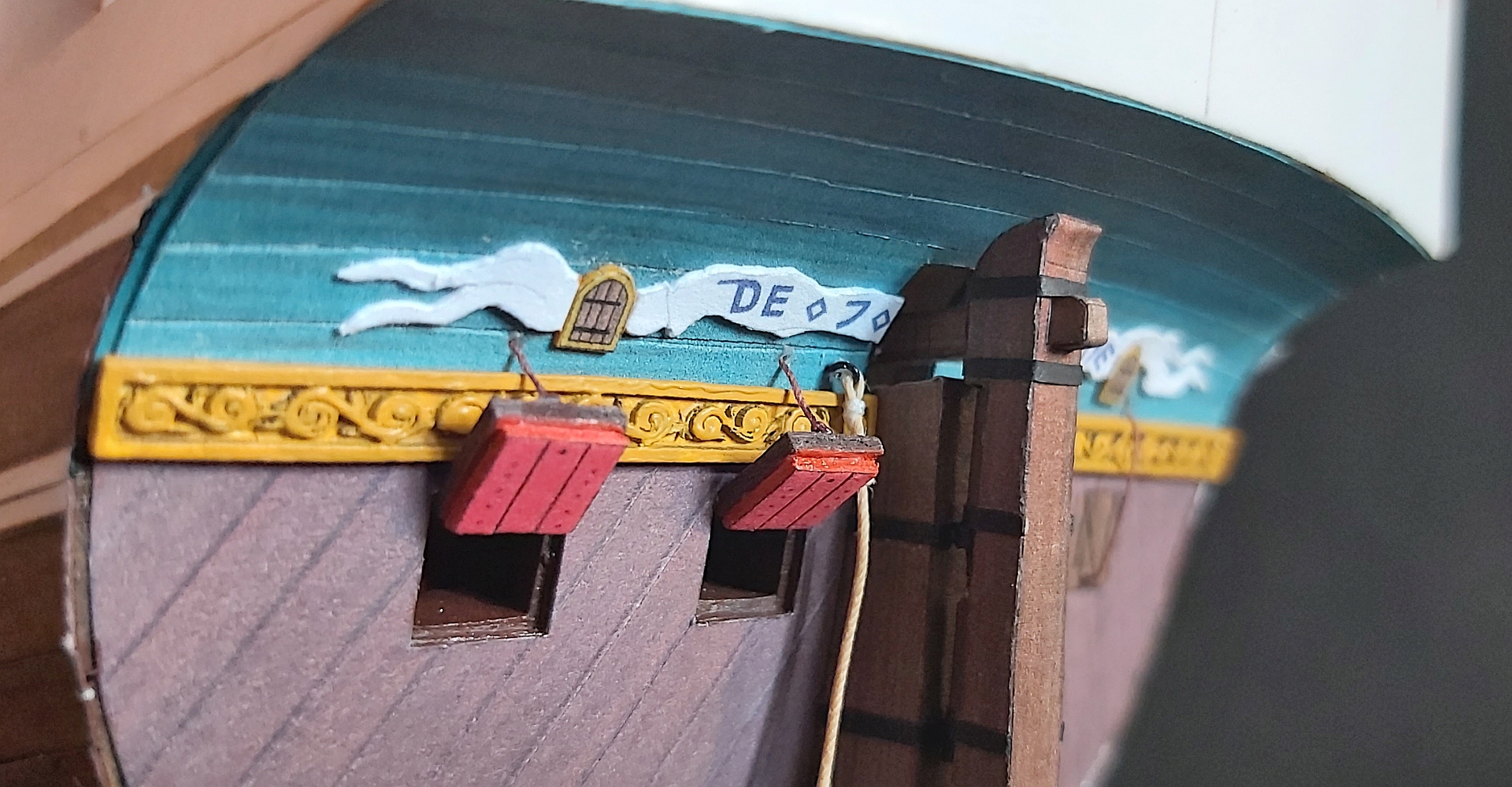
In the stern part there are belaying pins printed in resin , a bench and a rod on which the sheet of the second sail moved. And a few little things at the stern.
All decorations are "conventional", i.e. you can make others according to your own intuition and skills.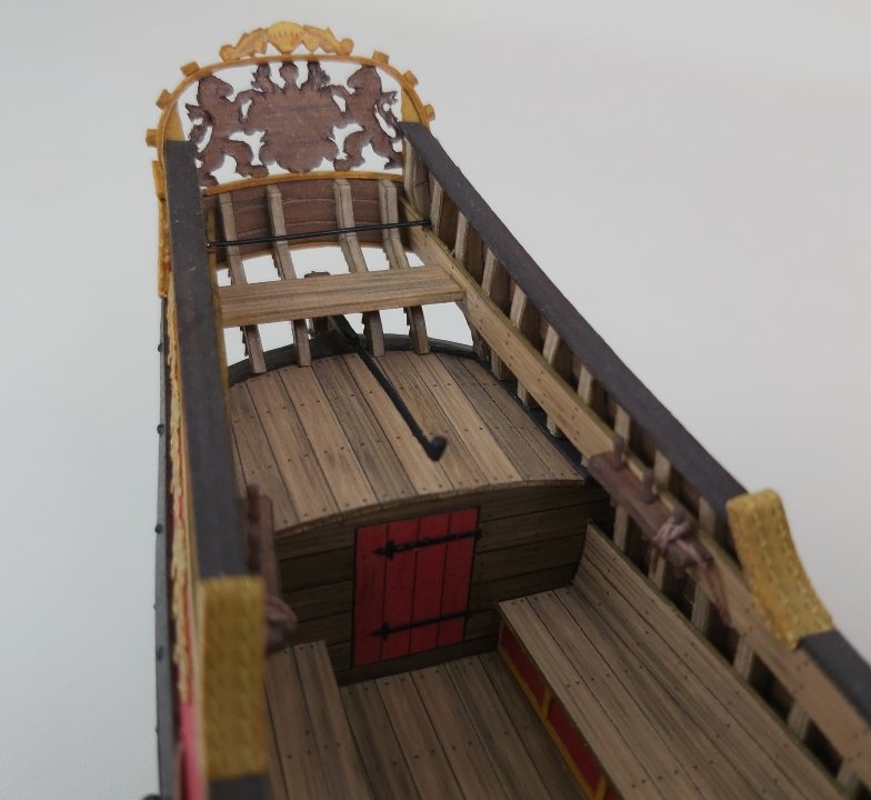
Leeboards, characteristic for coastal units that moved in shallow waters, according to the plans, had semi-circular indentations - after gluing such a part, I gently cut out these indentations with a scalpel, corrected them with a file and covered the whole thing with strips. They were hung with an eye on a hook coming from the side. They were lifted by ropes, which is clearly visible in the photos.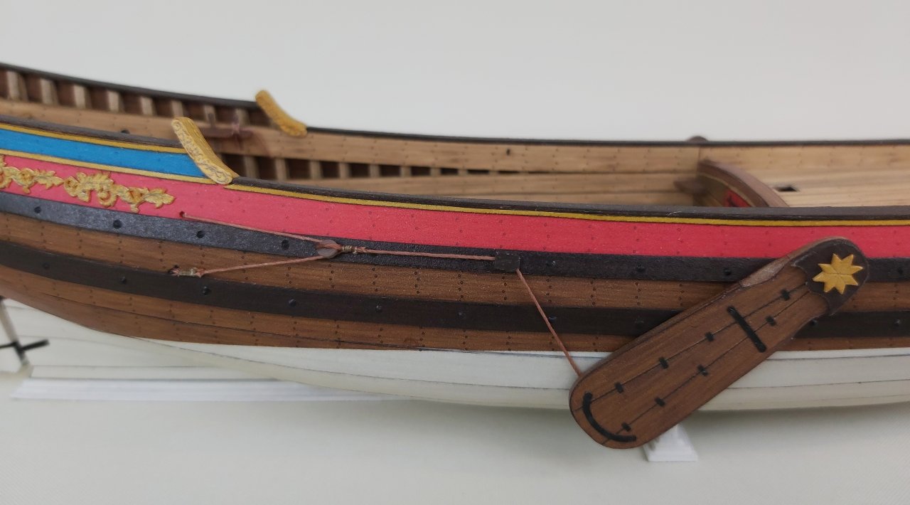
A few more words about the rudder blade, which unfortunately I don't have any photos of. A simplified version would consist of layers of cardboard and that's it. Usually, however, the rudder blade was thicker at the front edge and thinner at the rear. That's what I did: the side layers of 0.5 mm cardboard are glued together at the back, and an additional narrow strip of cardboard is glued between at the front. This can be seen on the masking strips. The front edge (where hinges are) was not perpendicular, but ended at an angle - the glued side parts in the color have appropriate protrusions at the front, which, glued together, create a triangular ending. The recesses for the hinge axles are, of course, masked with another small strips. The thicker upper part of the stern blade, where the tiller is mounted, was created by appropriate shaping and simply gluing thicker cardboard between. For imaginative modelers, instead of the missing photos, I am posting a scan of the parts.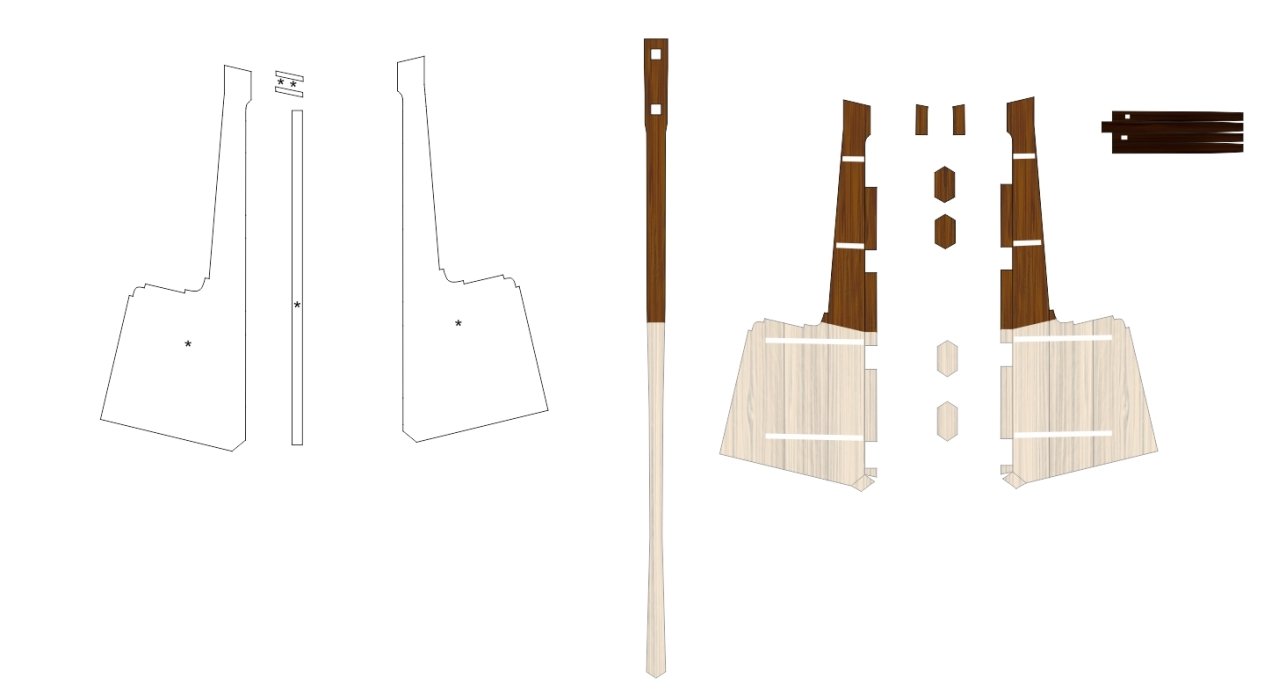
And that's all.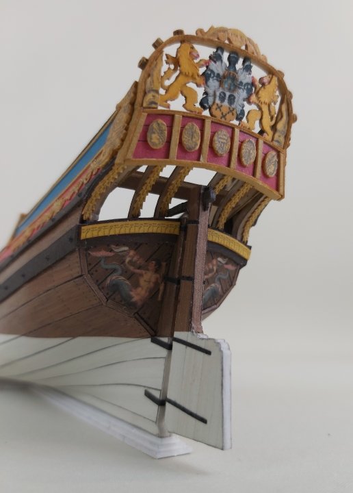
Regards
Tomek -
Hello colleagues
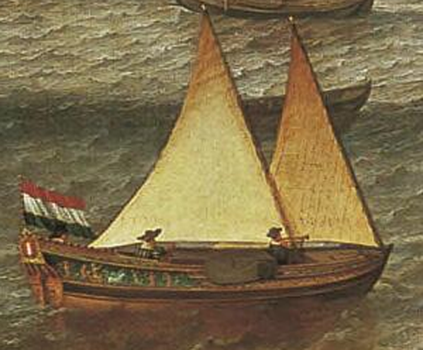
Many modeler friends said to me that it would be nice to assemble a cardboard sailing ship, but rigging is generally too difficult. Therefore, a few years ago I asked Ab Hoving for an idea for a simple model with the simplest possible rigging, and I didn't have to wait long (2-3 hours) when a precise and immediately three-dimensional design of a "recreational yacht" appeared on my computer. ", i.e. "Speeljacht".
This design is very similar to the commercially available plans drawn by Cor Emke.
[url]https://www.modelbouwtekeningen.nl/nvm-1006017-speeljacht-volgens-nicolaas-witsen-167.html[/url]Recreation on the water was probably not an invention of the Dutch, because in the tomb of Tutankhamun an image of the pharaoh fishing on the Nile was found, which can be considered entertainment on the water. However, until the 17th century, sailing ships of various types fulfilled basically only commercial and war functions or were used for work, such as fishing. It was only when the trade in Asia enabled merchants to build great fortunes that yachts for entertainment appeared.
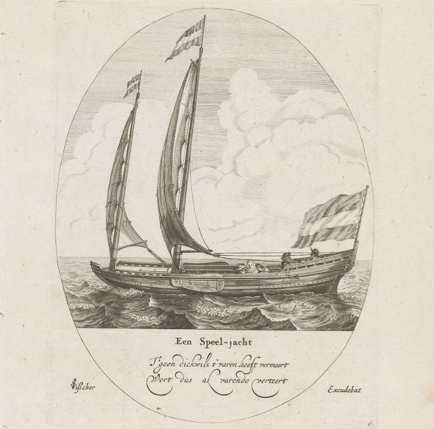
Maybe it was then that "yachting" appeared as a way of spending time with family, friends or for business purposes. Not only did people relax by sailing for pleasure, but such expeditions were accompanied by delicious feasts, including plenty of drinks. Nicolaes Witsen even mentions a "beer house" under the aft deck. In addition to romantic trips, owning such a yacht meant prestige and/or wealth - a bit like modern billionaires and oligarchs.
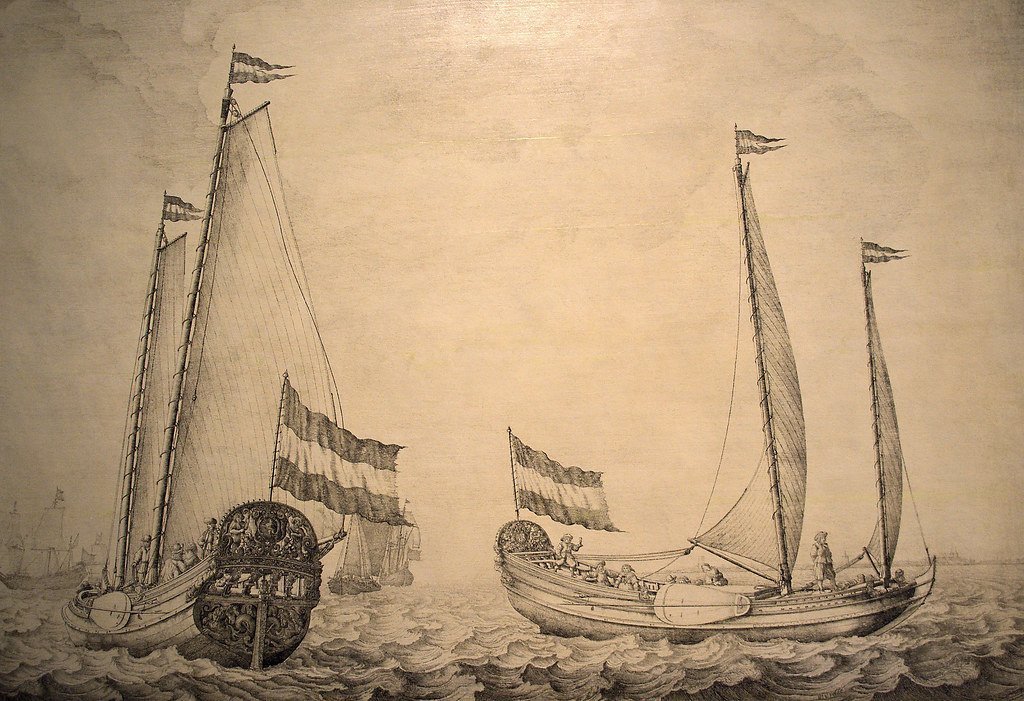
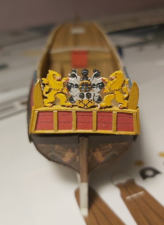
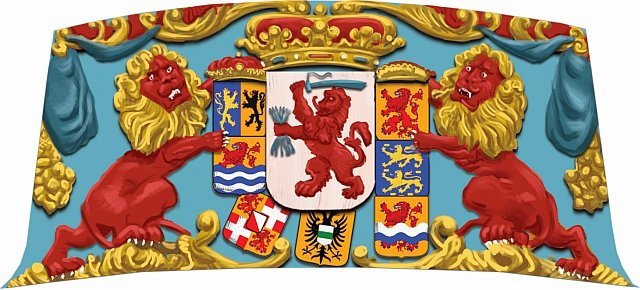
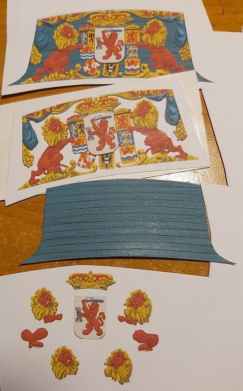
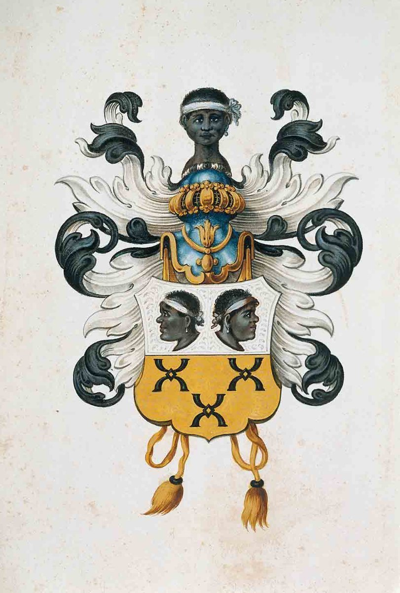
The decorations were chic, but not flashy. The Netherlands was a Calvinist country, so one had to be modest. There was usually a family coat of arms on the stern.
A similar model was developed in wood by Kalderstock.
And for the inquisitive and curious: the Clean2Anywhere Foundation has been experimentally recycling plastic for several years, building replicas of small historical yachts from it, including this speel yacht. Link to one of the videos where you can see the construction of a speel yacht:
[url]https://www.youtube.com/watch?v=eqrIHFulcZU&t=3s[/url]
And how is my construction going? So quick and easy that I didn't take many photos, especially obvious stages like frame frames,...
...or "first - false planking"
The retouched cardboard edges of decks has always "disgusted" me, so I experimented a bit and glued narrow strips on the visible edges, imitating the face of the boards. The stripe is 0.7 mm, my hand trembled a bit and it didn't turn out perfect, but I think it's a very good idea for the future.
Since masking the edges like this has a future, I went ahead and played with the edges of the planks at the stern. There is also something to complain about, but that's my fault - I liked the idea itself.
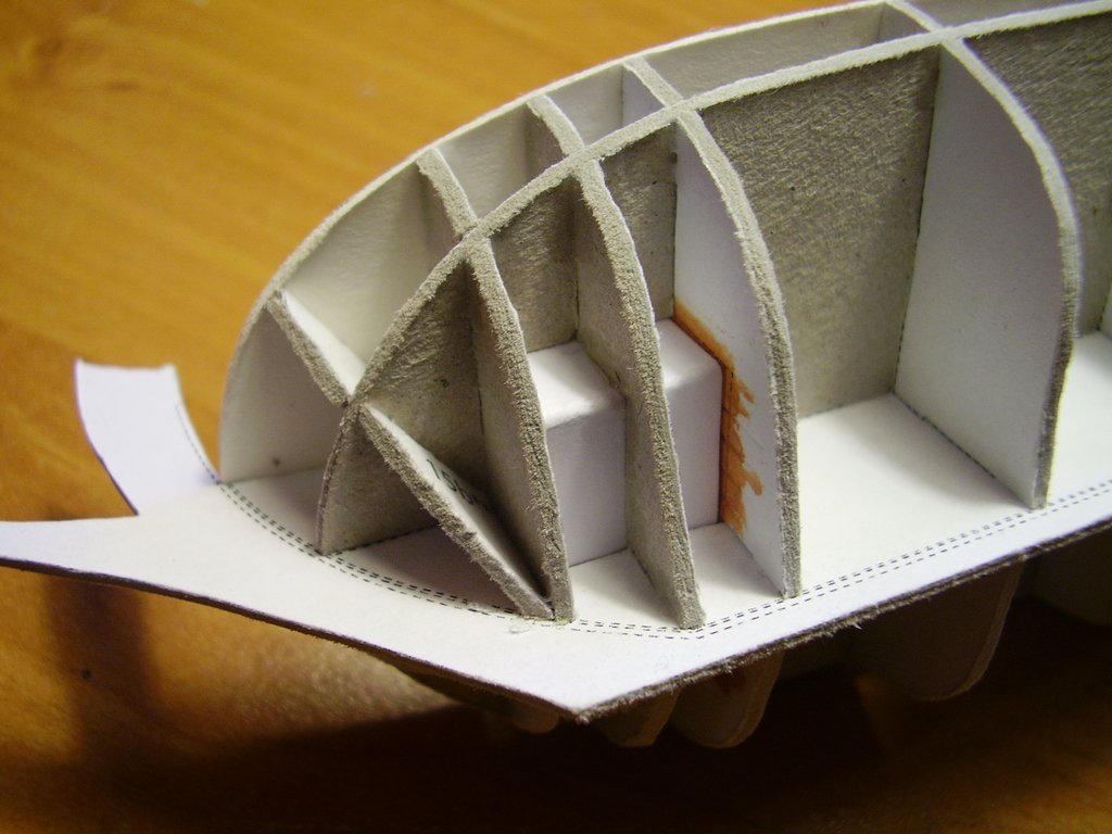
A large number of visible frames required tedious gluing and retouching, and initially I planned to glue them to the hull first and then continue covering them with the planks. Fortunately, before I started committing such stupidity, I changed my concept and built this component separately, finally gluing the finished one to the model. In total, in four stages: 2 amidships and 2 aft.
The last layer of planks (in color) went very well, and of course the corrections were made on the edges that are covered with wales. This is how it turned out:
Modest decorations (as I wrote at the beginning) will only be made of cardboard (no resin), so that the model is fully paper as standard. It was necessary to choose the coat of arms of some noble family. The final choice fell on the van Loon family, also because their "palace" still houses a popular museum.([url]https://www.museumvanloon.nl[/url])

That's it for now, only decorations, leeboards and very simple rigging remain.
Regards
Tomek
-
On 2/29/2024 at 11:39 PM, ccoyle said:
Yes, but he's talking about recent activity. That I can't vouch for, but perhaps some of our European connections, such as @0Seahorse, can shed more light.
I don't know exactly how Bumażnoje Modelirowanie currently works. I heard that they print in Poland and the current internet address is probably/maybe/perhaps/not sure https://papermodeling.net/index.php?route=information/information&information_id=4. Many stores in Poland (Orlik, WAK, GPM) have their models, so you can alternatively look here.
-
Hello Jeff
You perfectly interpreted the markings on the rigging drawings (bloks, cleats, eyebolts). It's exactly as you marked a-b-c. The same applies to attaching blocks to masts. That's exactly what I meant. And you also read the jib boom shift correctly, although of course these all solutions is only my suggestion based on the sources I had at my disposal.
Tomek
-
Hello Jeff
Somehow I missed the fact that you started building this model and didn't suggest a few important things ahead of time. But I'm glad you reached this stage of construction and "conquered" the hull. In cardboard models of sailing ships, the hull is the most critical element of the structure - you cannot use sandpaper to correct something or to narrow the plank by 0.2 mm.What would certainly make construction easier at the very beginning is grinding the frames at appropriate angles, just like when building from wood. I take this into account in all my designs (this hull was not designed by me, but it always works). Of course, the sanding itself should be gentle. If there is no grinding, subsequent layers (parts) become too short. Below is a photo of the frames of different model polished so that all "transitions" are smooth.
If a plank (from the last colored layer) is too short, you can glue them a few centimeters at a time and gradually "stretch" the paper using water-based glue (this type of glue softens the paper and changes its dimensions). Of course, such stretching must be done carefully to ensure just don't tear it apart.
I regret that I did not present the construction of the model on this forum, which would be helpful for you. If you need more pictures, there are some presentations on Polish cardboard model forums.
I will be watching your build with interest.
Tomek
- ccoyle, Canute, modeller_masa and 5 others
-
 8
8
-
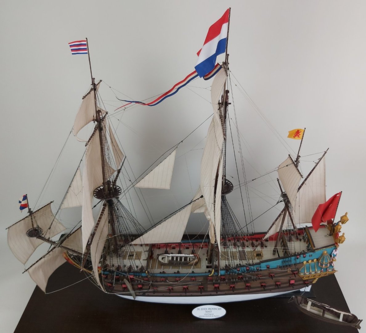
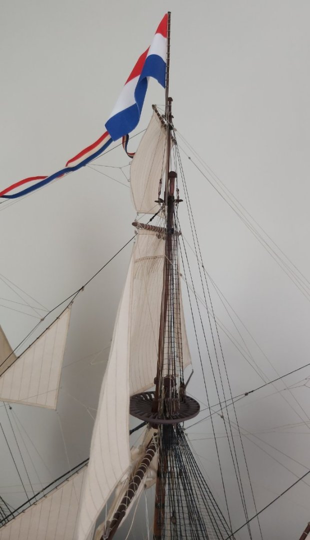
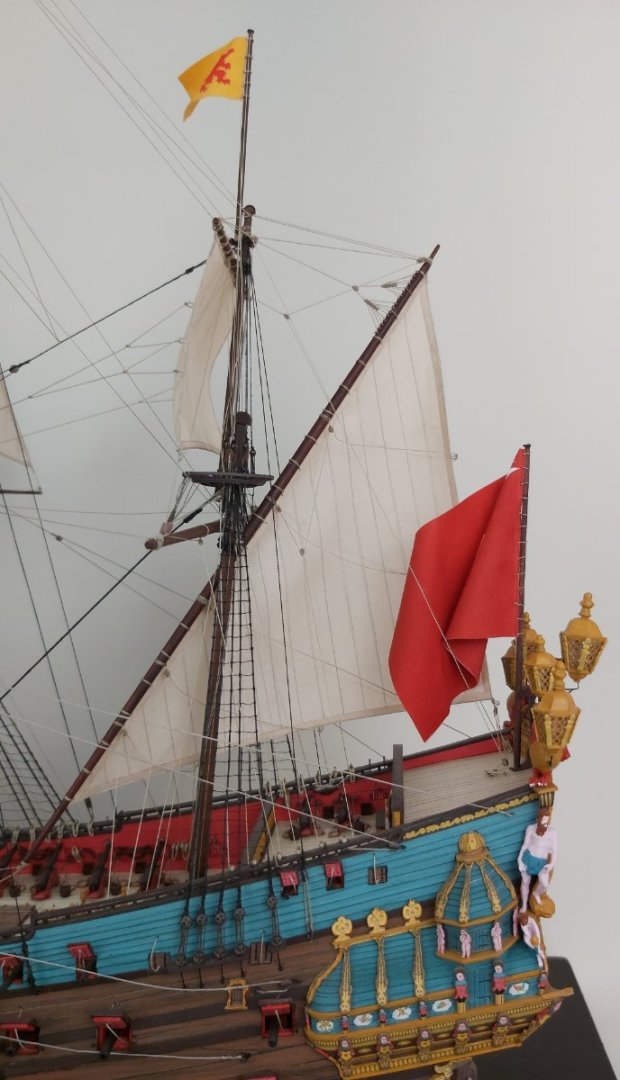
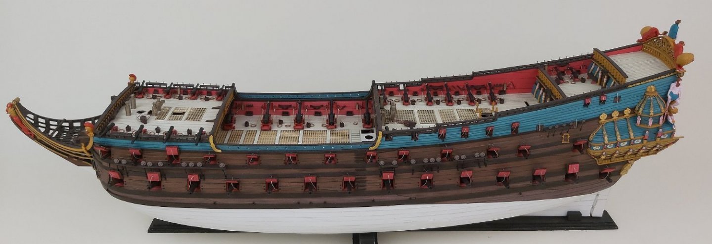
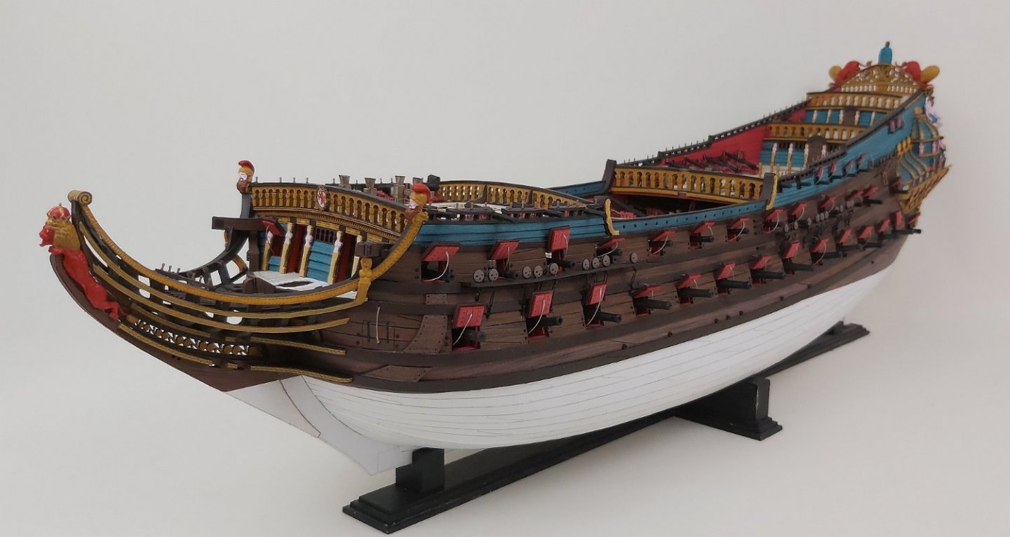
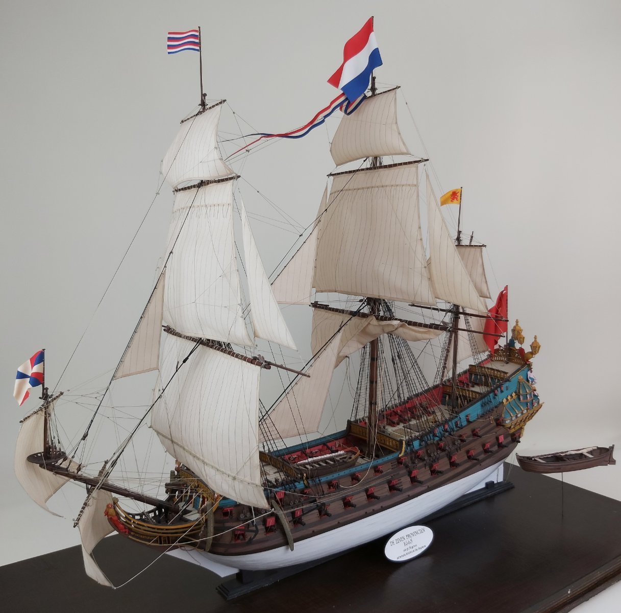
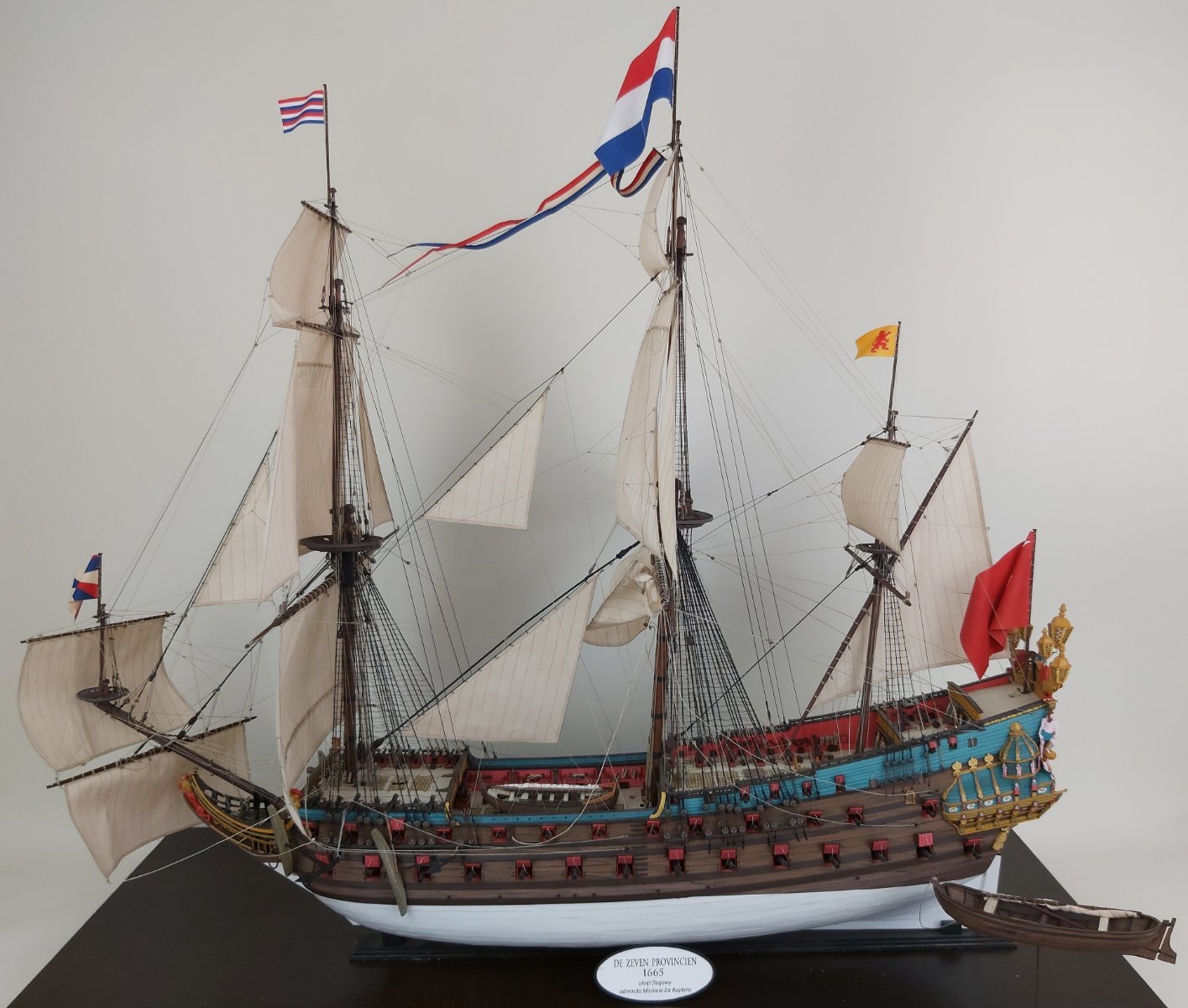
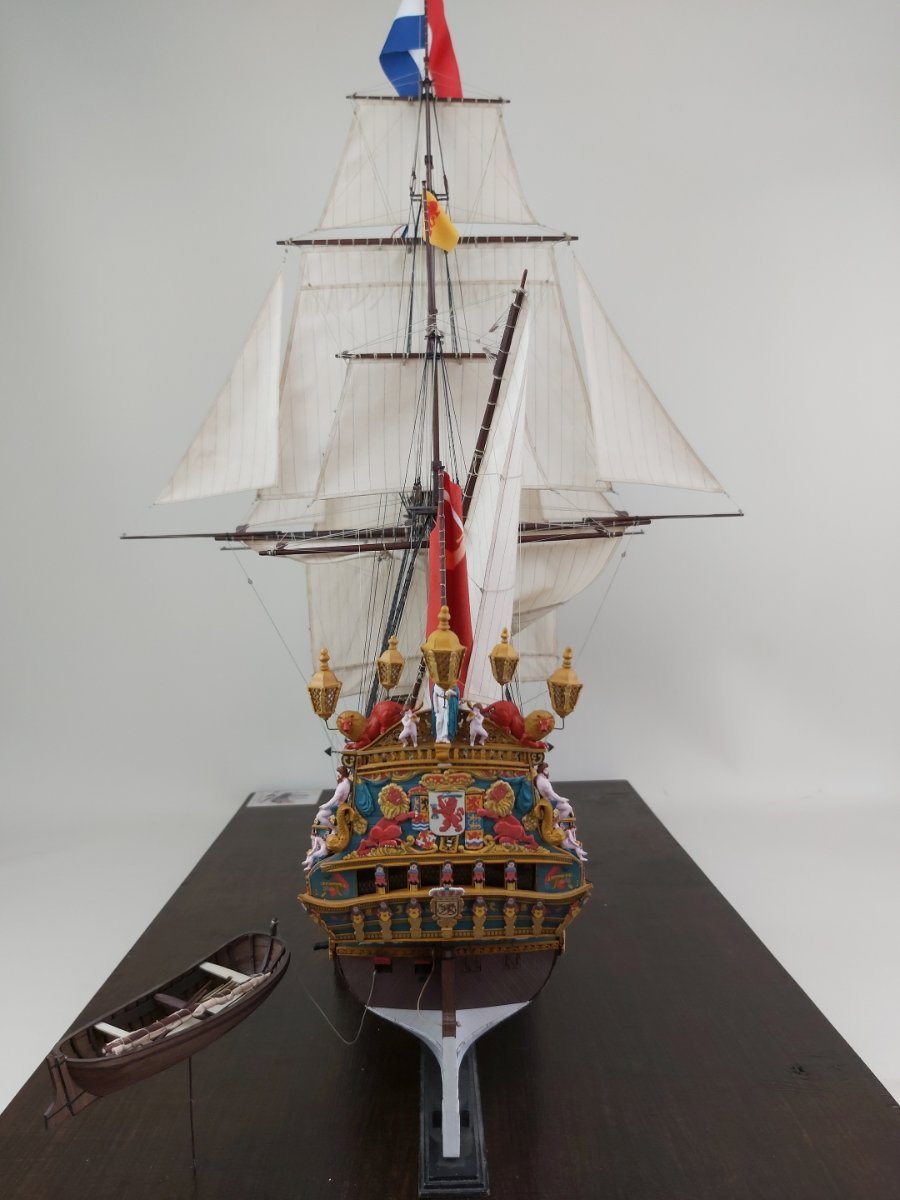
Hi everybody,
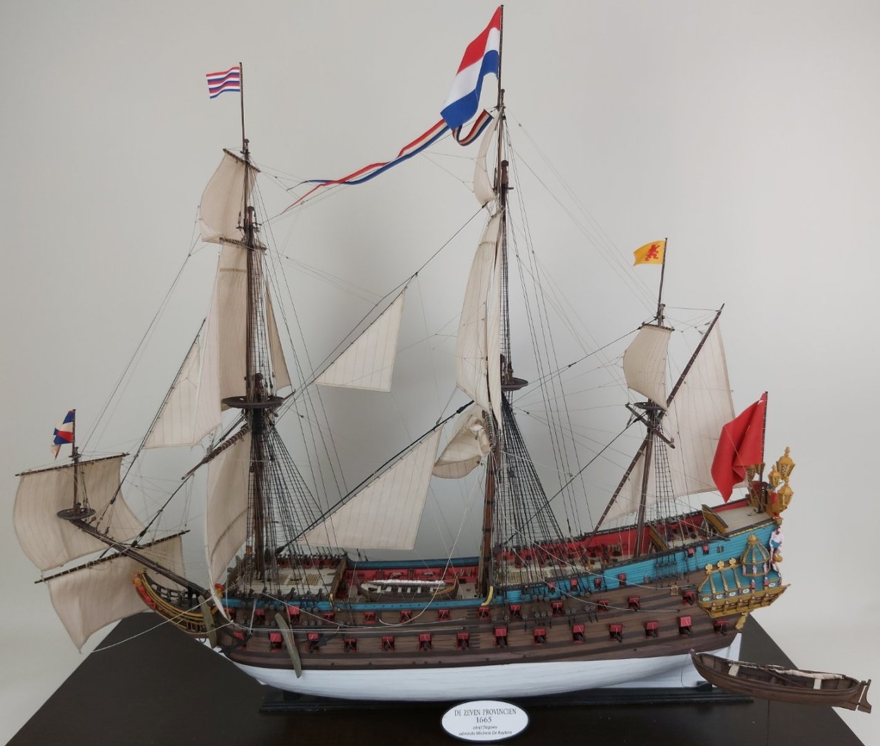
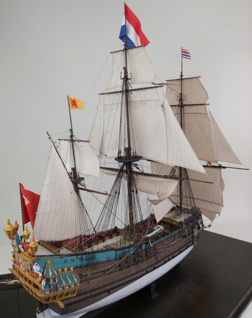
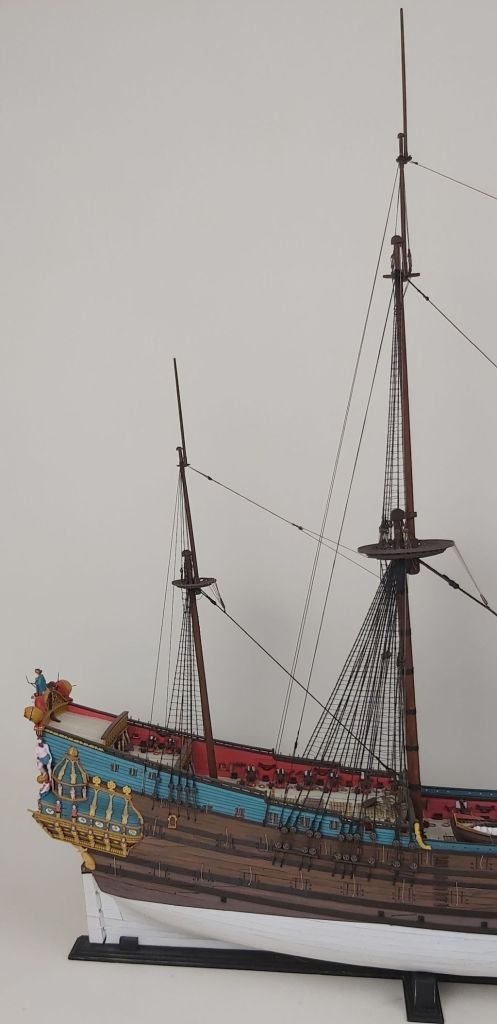
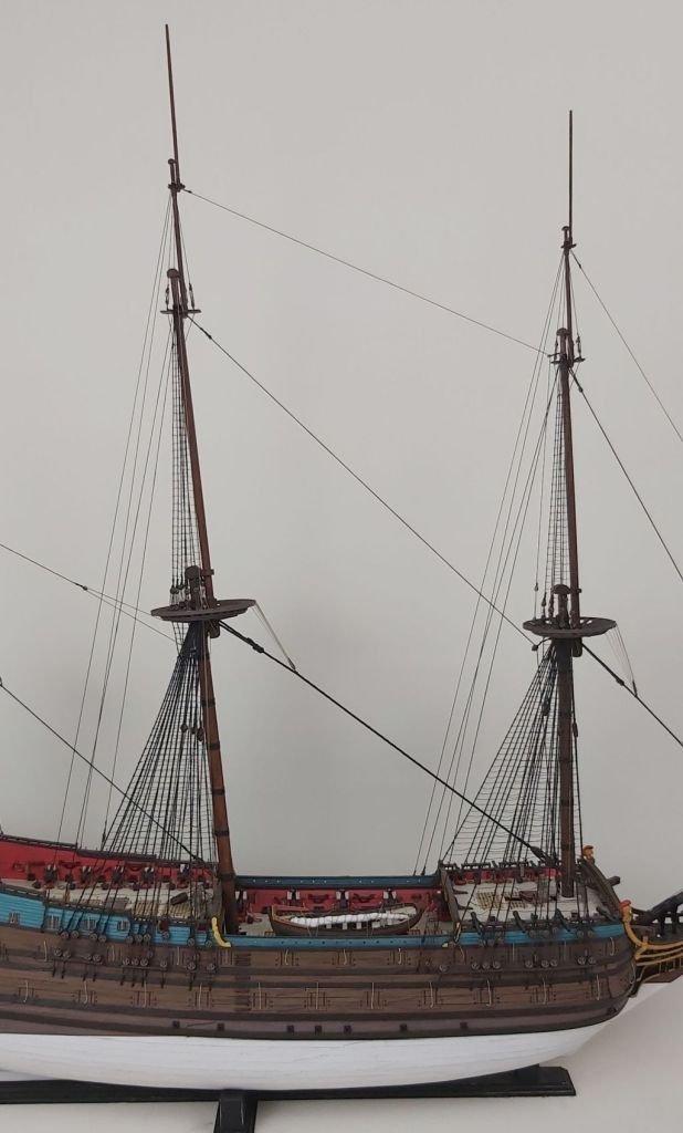
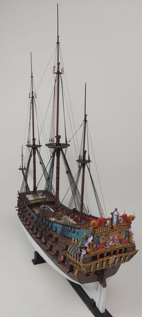
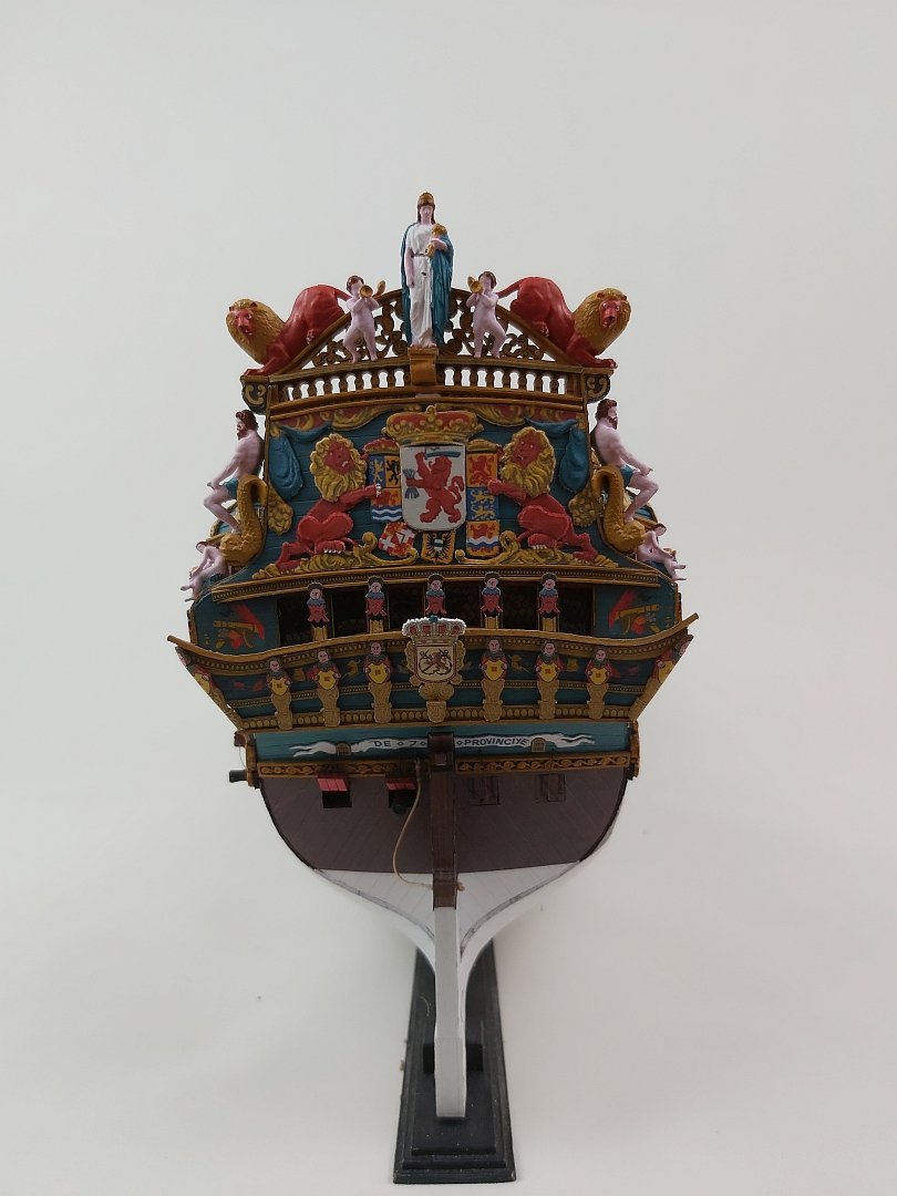
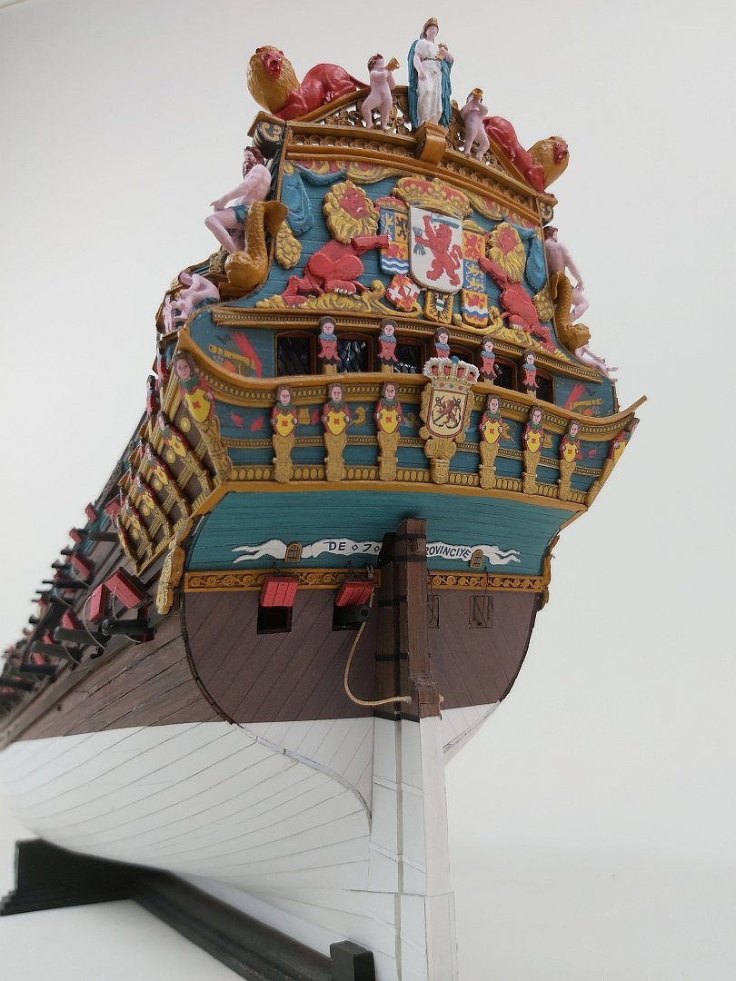
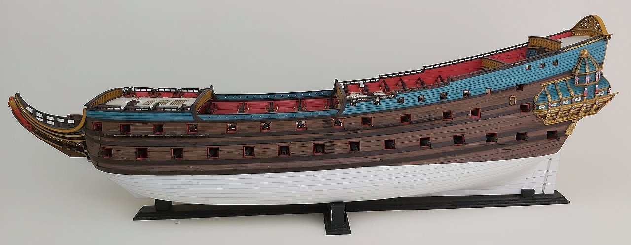
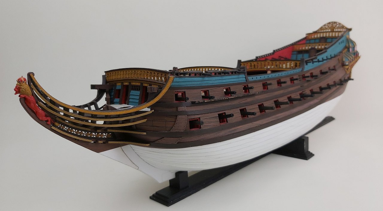
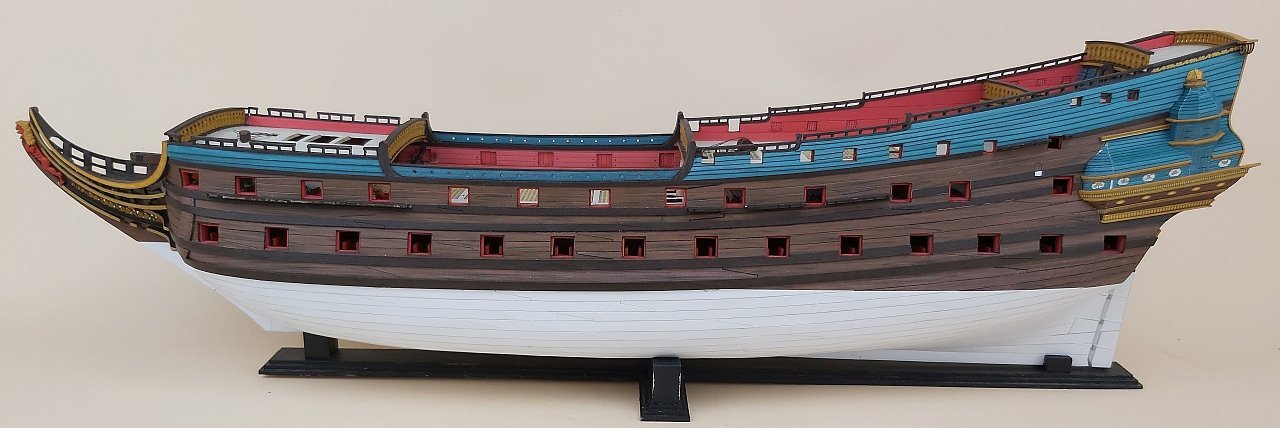
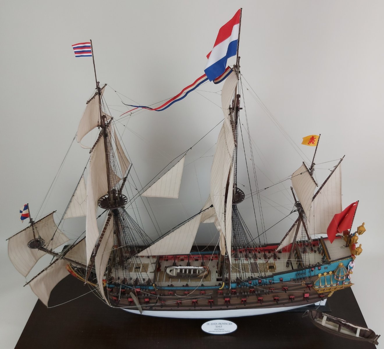
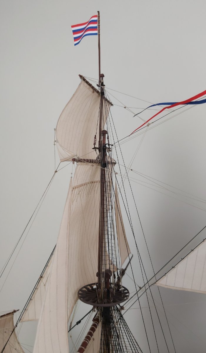
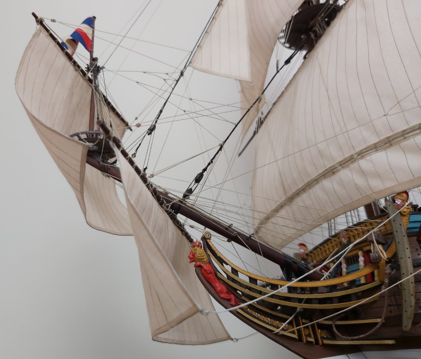
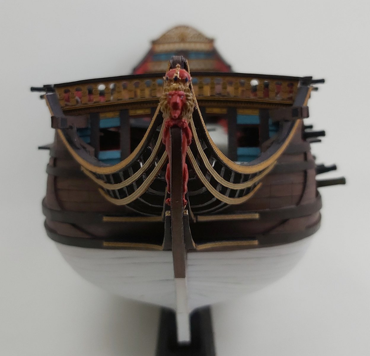
yes, many months have passed since the last update, but I finally have something to be proud of - last night I raised the last flag and today I can show the completed model of the flagship "De Zeven Provincien". Thanks again to Ab Hoving, who constantly supported me, advised me and cheered me on until the last day of working on the model.
Running rigging is so extensive that you can write an essay on what, how, where, what to watch out for, what to ignore, etc. I won't hide the fact that I simplified a few elements or simply "fooled" the human eye. I don't know how many ropes and threads are finally attached to the model.
Although it was unlikely that all the sails were set at the same time, I decided as a test (after all, it is a test model) to hang the stay sails to make sure that there were no errors in the instructions or that any of the lines were placed absurdly. I used various sources, but I may have misinterpreted something (especially since some sources were in Dutch). Surprisingly, I found only one error (the designations of ropes 72 and 82 were swapped). I attached the rest of them according to the instructions and it worked.
I made the first drawings in the project in the spring of 2017 (my daughter was 10, now 16).
A handful of photos, comments and questions are welcome


-
-
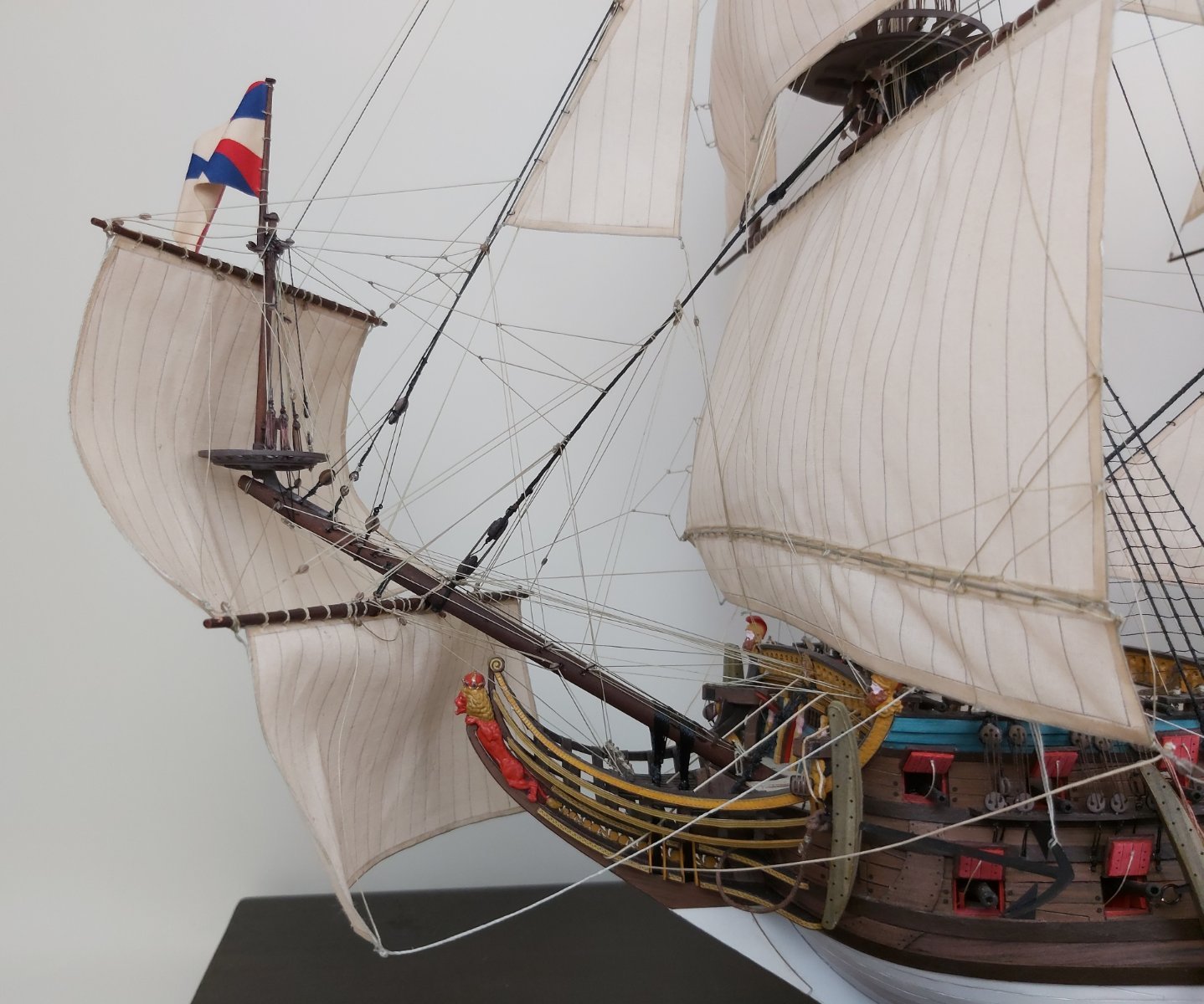
Hello,
I can't believe it's been so long since the last update.
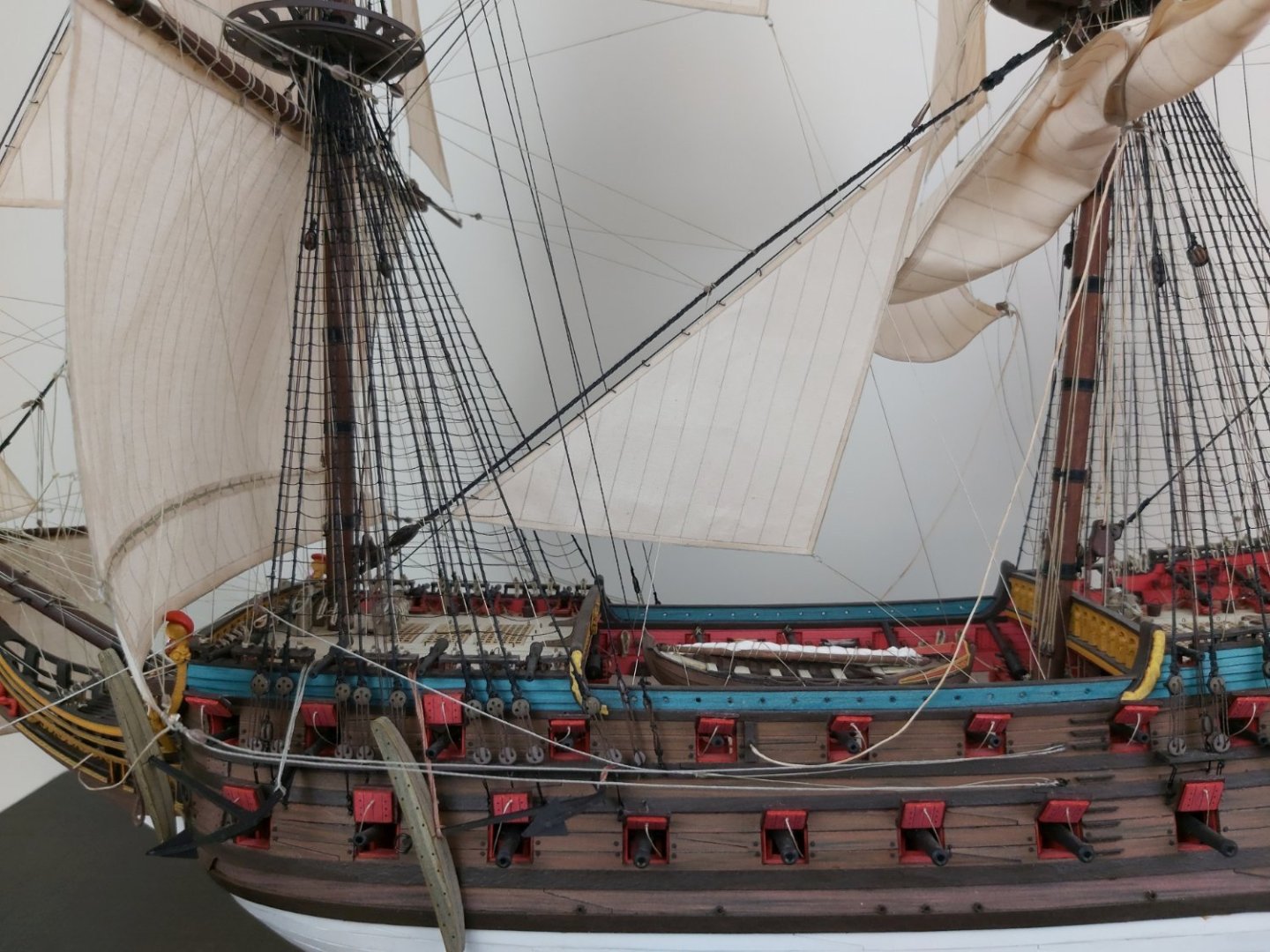
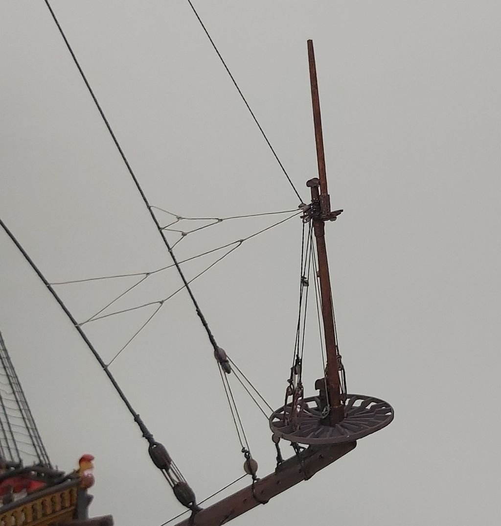
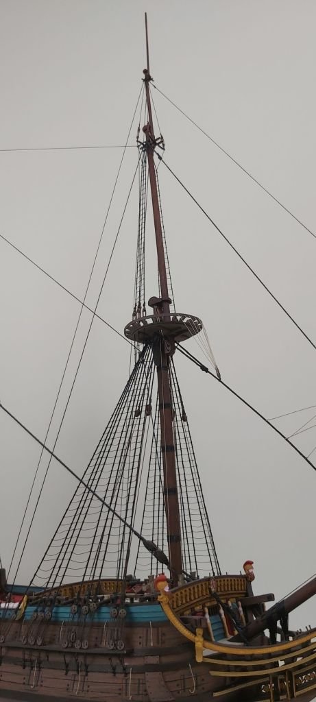
I have put up all the masts and I think you can say that the standing rigging is ready. Most components built/rigged as planned. A slight problem arose with the bowsprit mast and the foremast: both leaned back slightly when tensioning the stays, which was not matched by the stiffness of the bowsprit (it moved up a little). I am satisfied with the symmetry: with such a large sailing ship, I managed it almost perfectly. Some time ago, the model, unfinished but secured in the "aquarium", made its first cruise at the Model Show in Nowy Tomyśl. The latest photos of "De Zeven Provincien":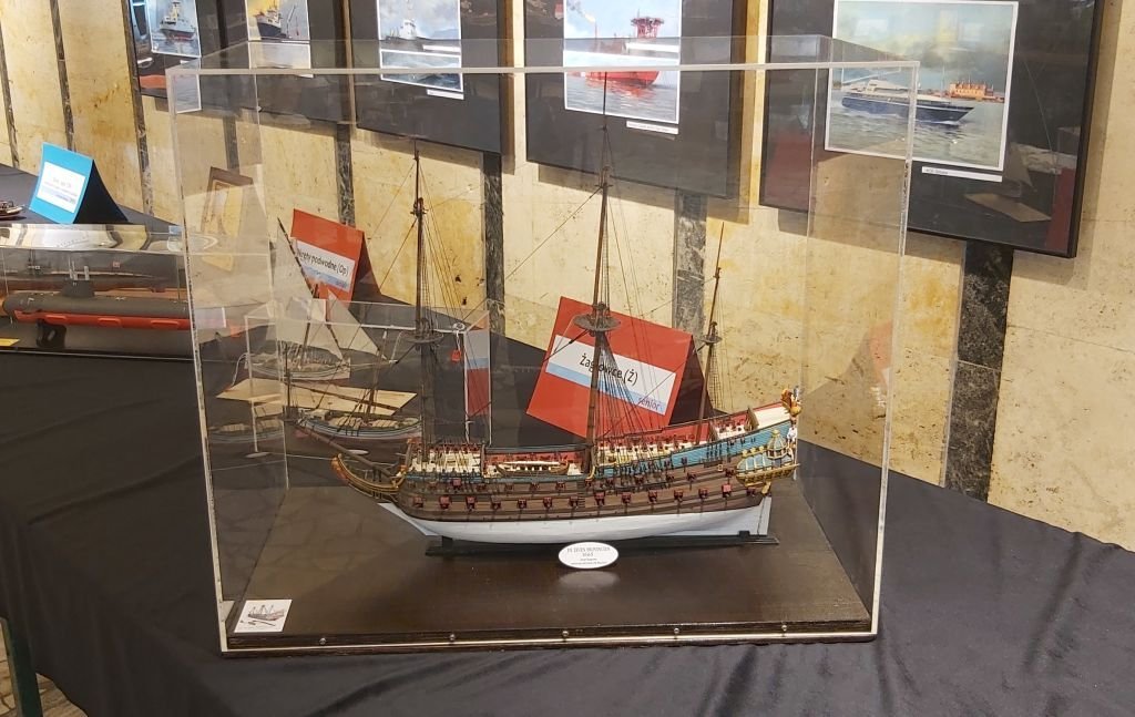
Tomek
-
Hi everyone,
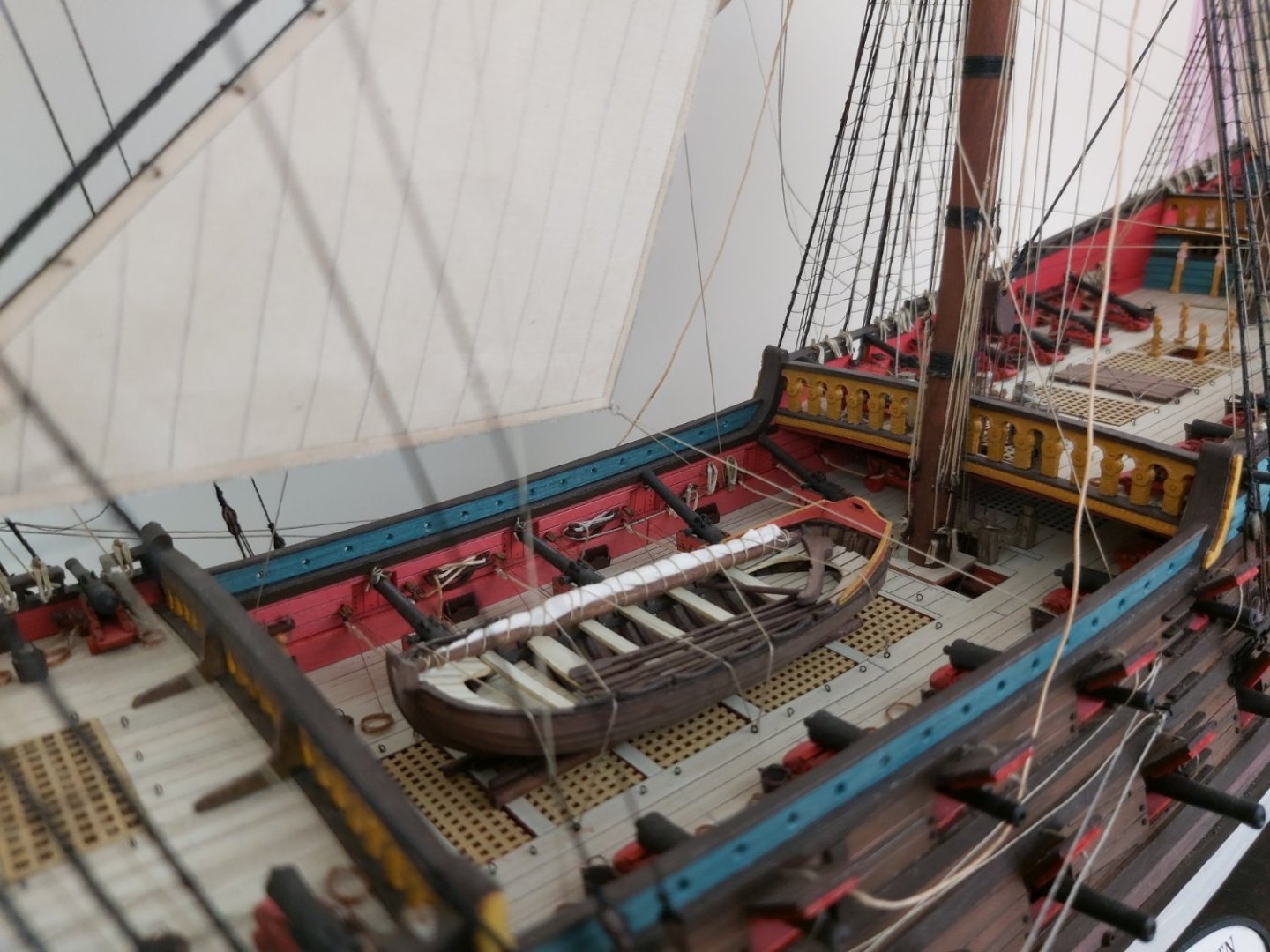
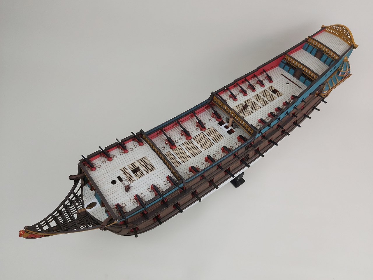
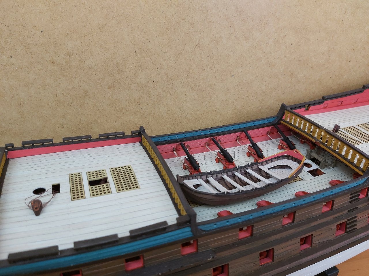
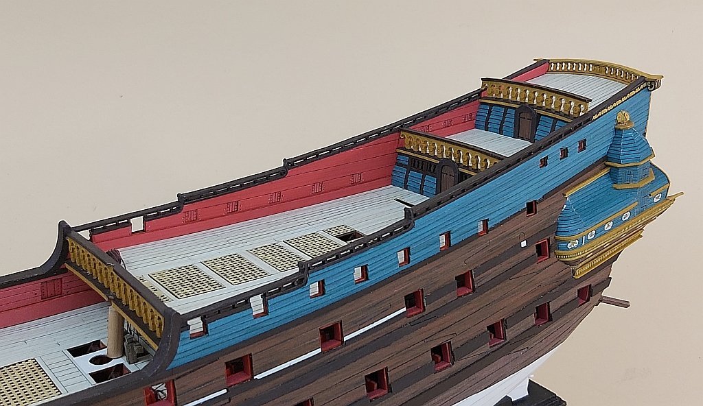
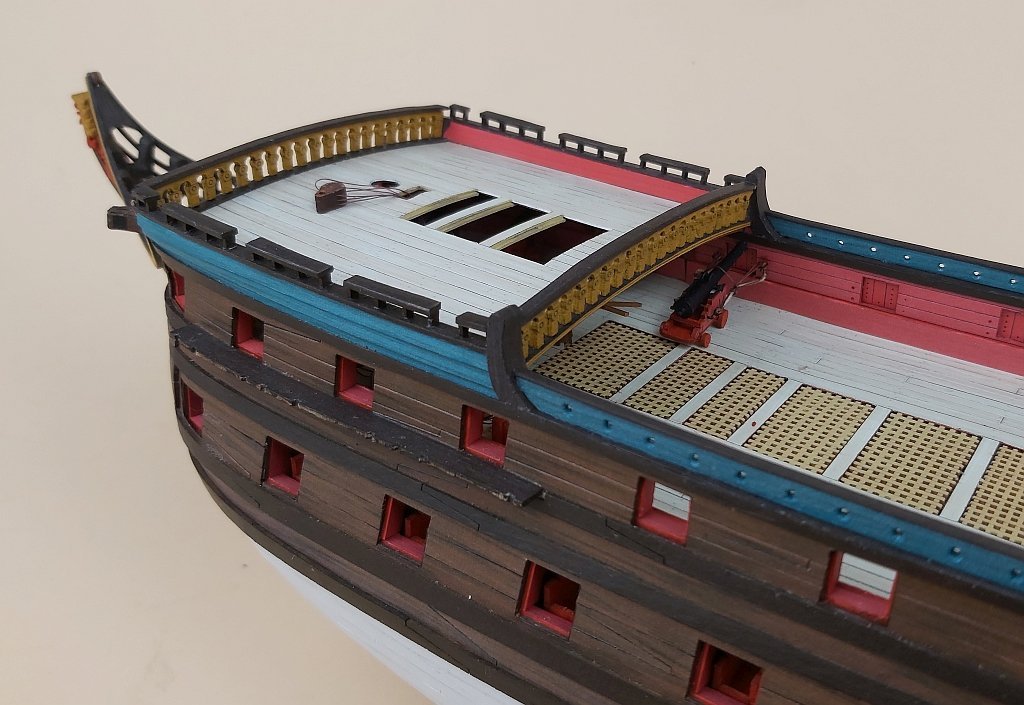
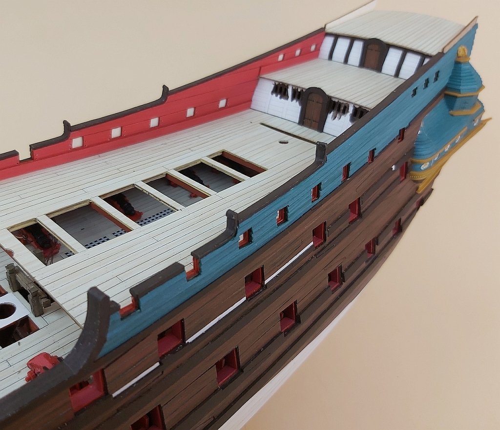
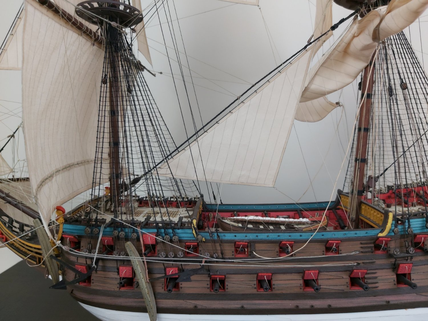
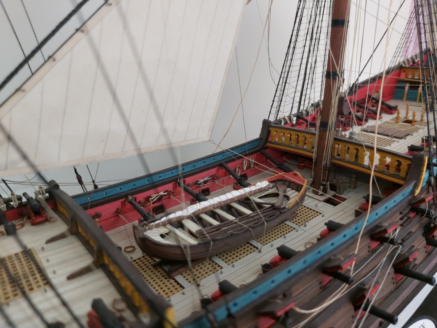
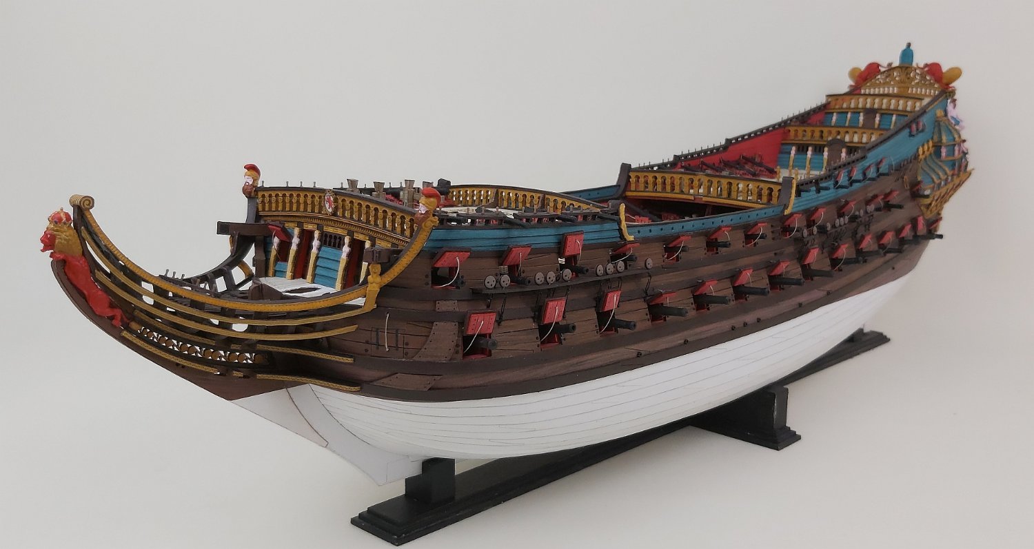
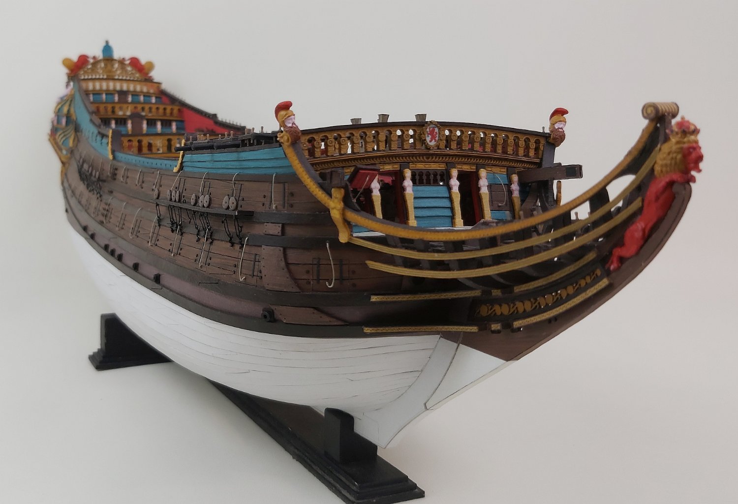
Some time has passed since the last update, but it was not time wasted because I can announce that I have finished working on the hull of "De Zeven Provincien" !!! Hurrah!!!!
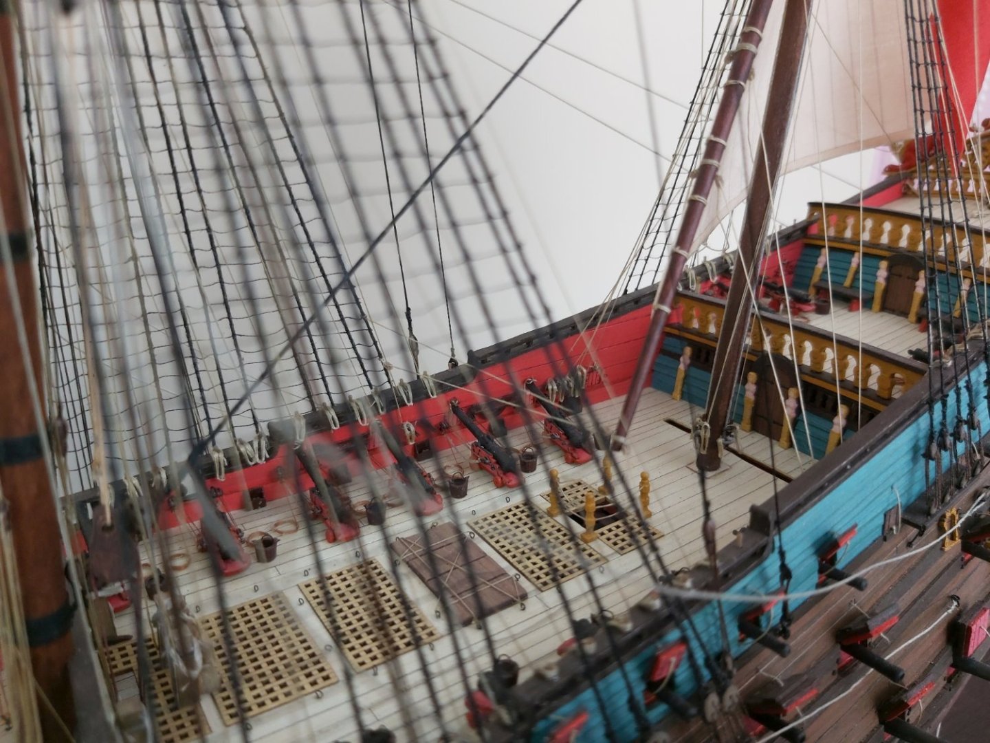
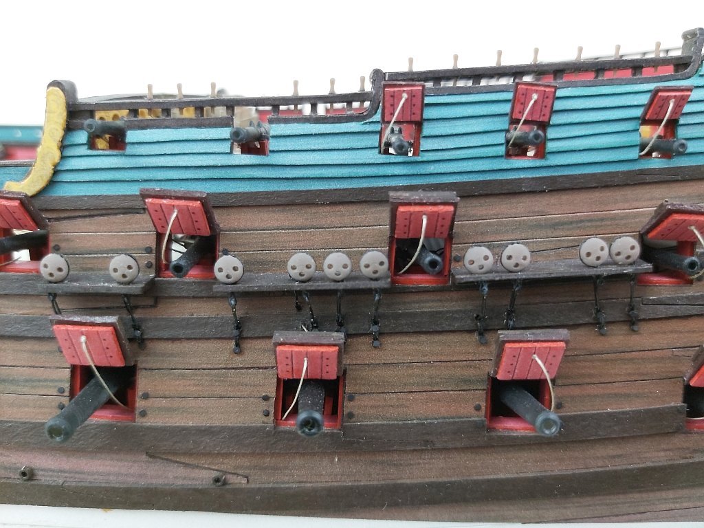
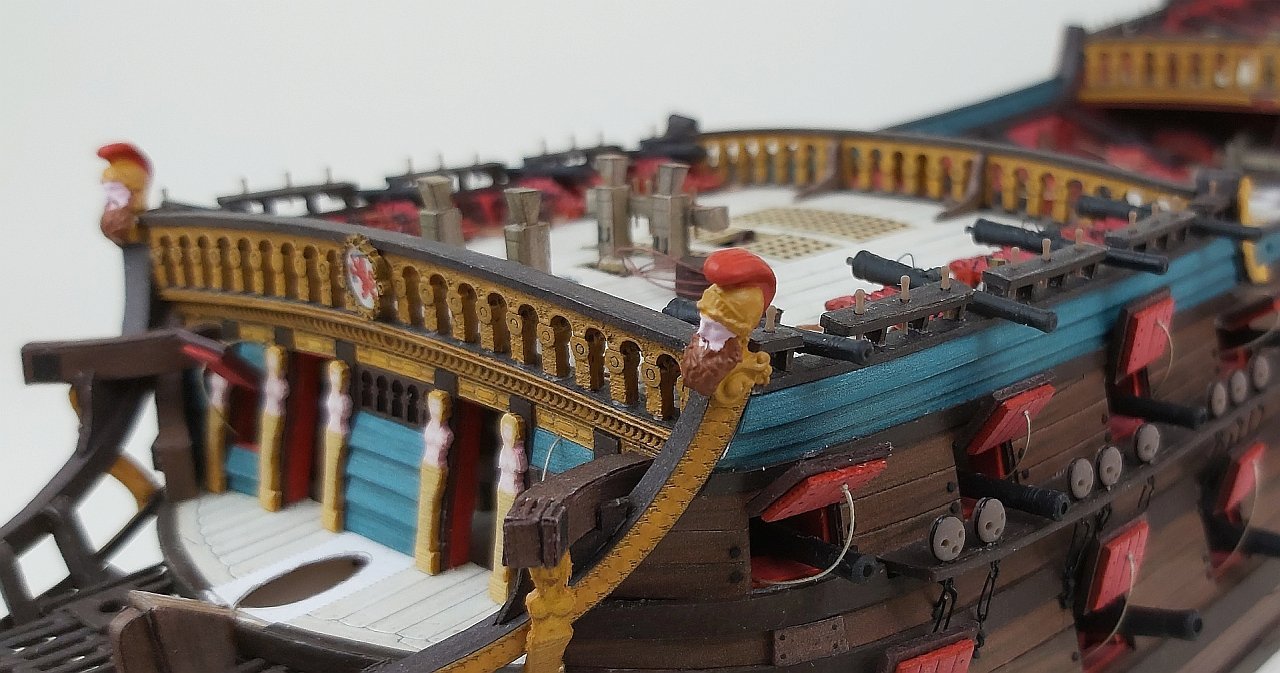
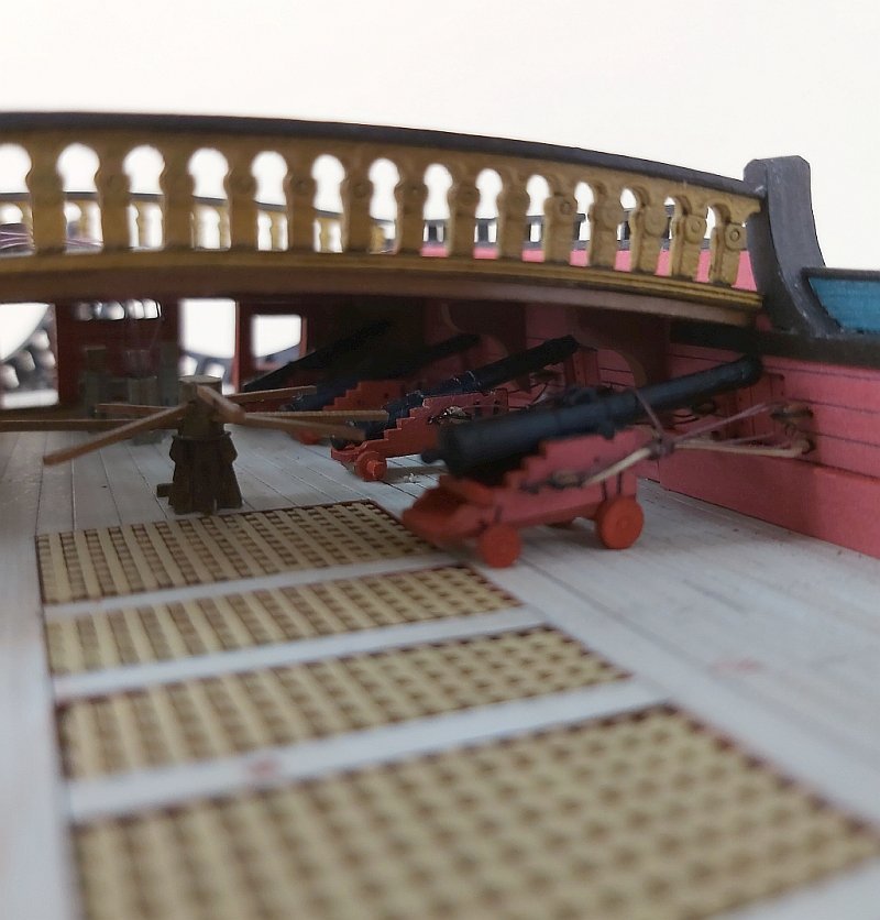
I made gunport lids (I have a slightly "bent" eye, because a large part of them is slightly twisted in the same direction; similarly with the holes for the ropes lifting these covers, they are all slightly shifted to the left :-))) There was a lot of work on the starboard too, because I did not print the hinges for gunport lids, believing that sticking thin strips would be nicer. I don't know if it's nicer (probably not), but it's definitely more time-consuming.
But after dealing with nearly 80 gunport lids, it looked better and better. At the same time, I had to make deadeye attachments because it was getting tight in some places. In fact, I didn't simplify them, I just changed the shape of two lower parts (1 and 2), which I covered with small circles (3). Details in the drawing.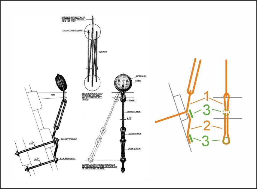
Adding various types of riggin equipment to the bulwarks and decks is a normal job and nothing interesting to write about.
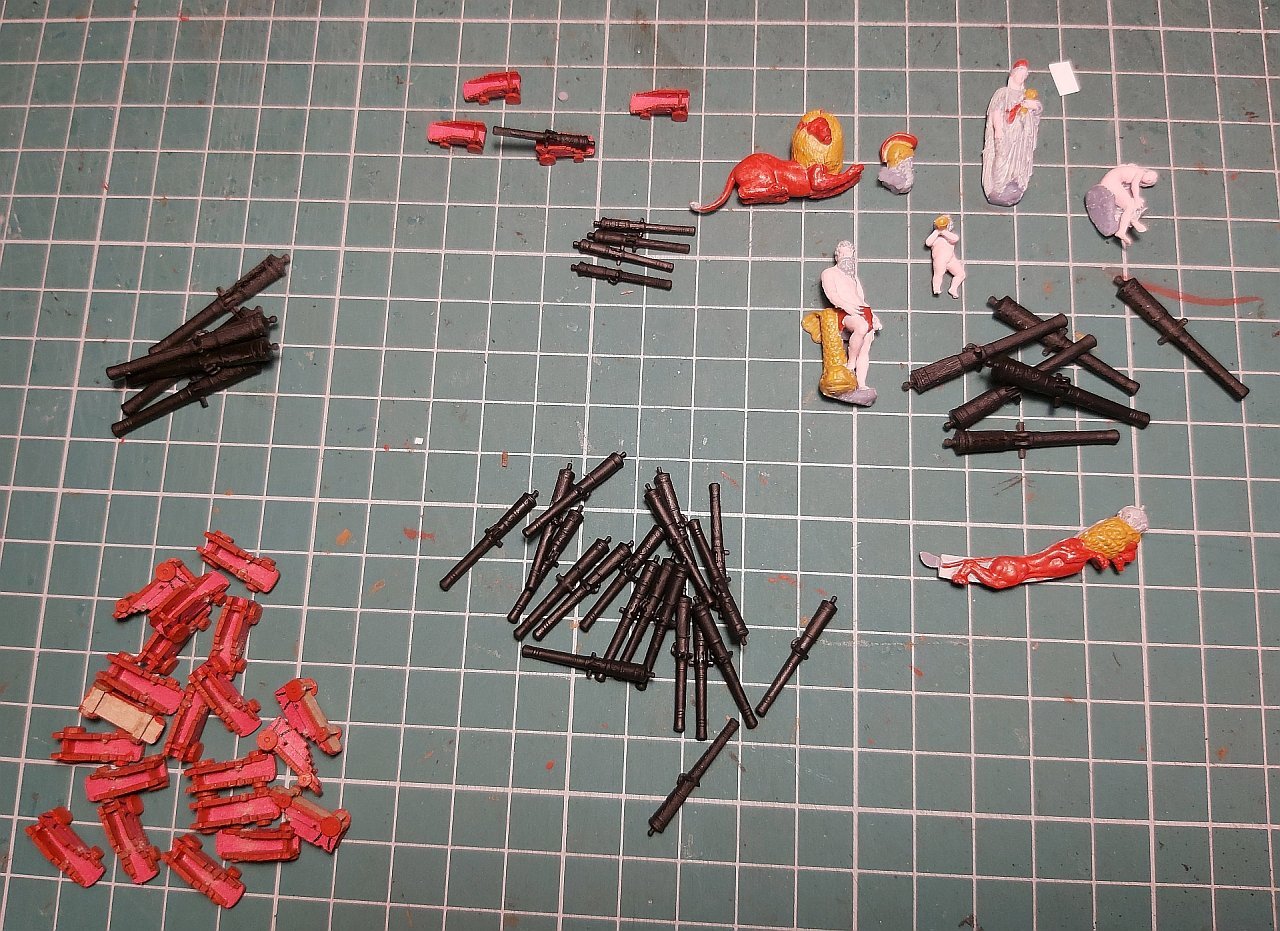
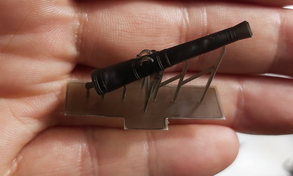
I helped myself with a 3d printer again and it was a move almost brilliant :-))) I printed 180 belaying pins: delicate, small, nicely contoured shapes. The end result and the time needed for them is incomparable to those made of wire and thickened on top with a drop of thick glue. I am delighted with this solution, especially since I printed in brown resin right away (pigments are not cheap, but the time savings justify the expense)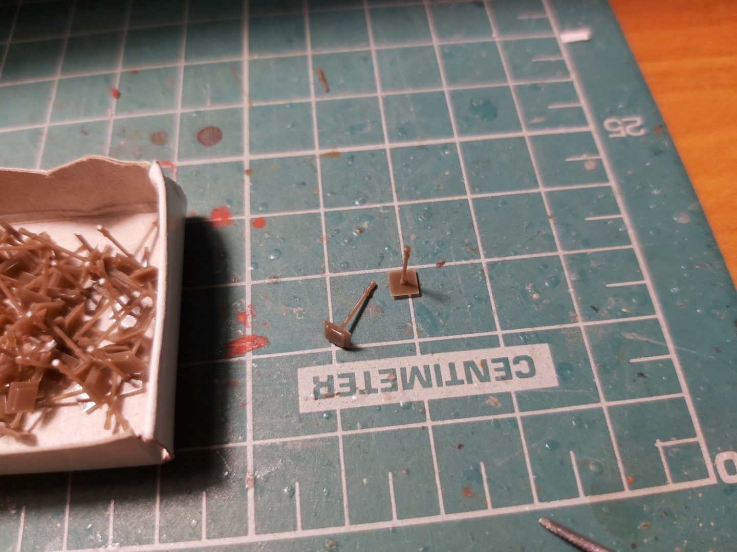
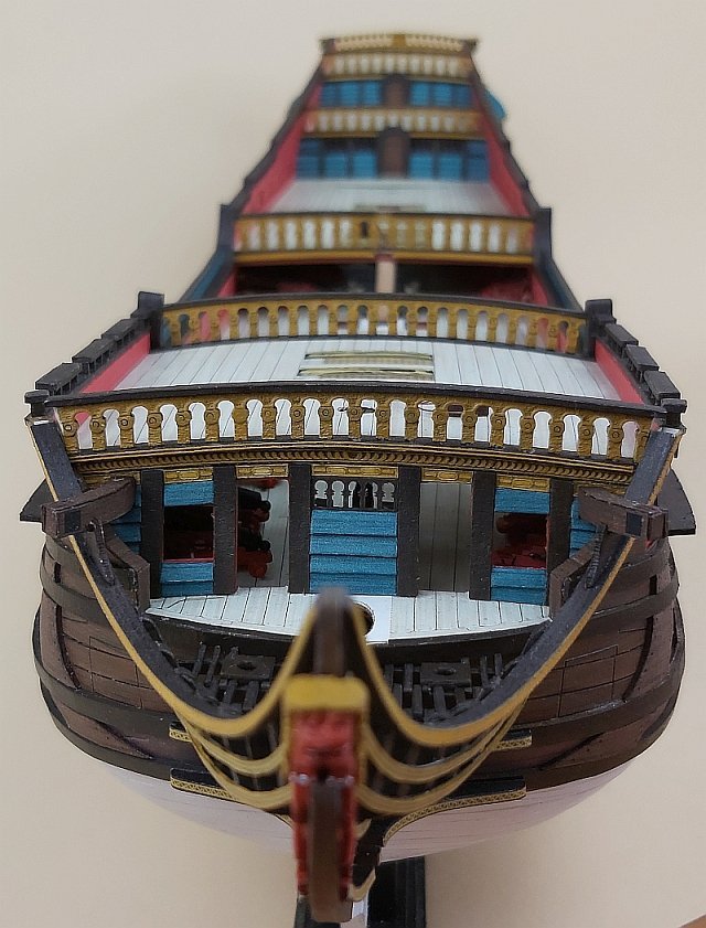
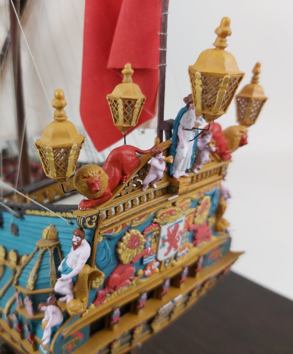
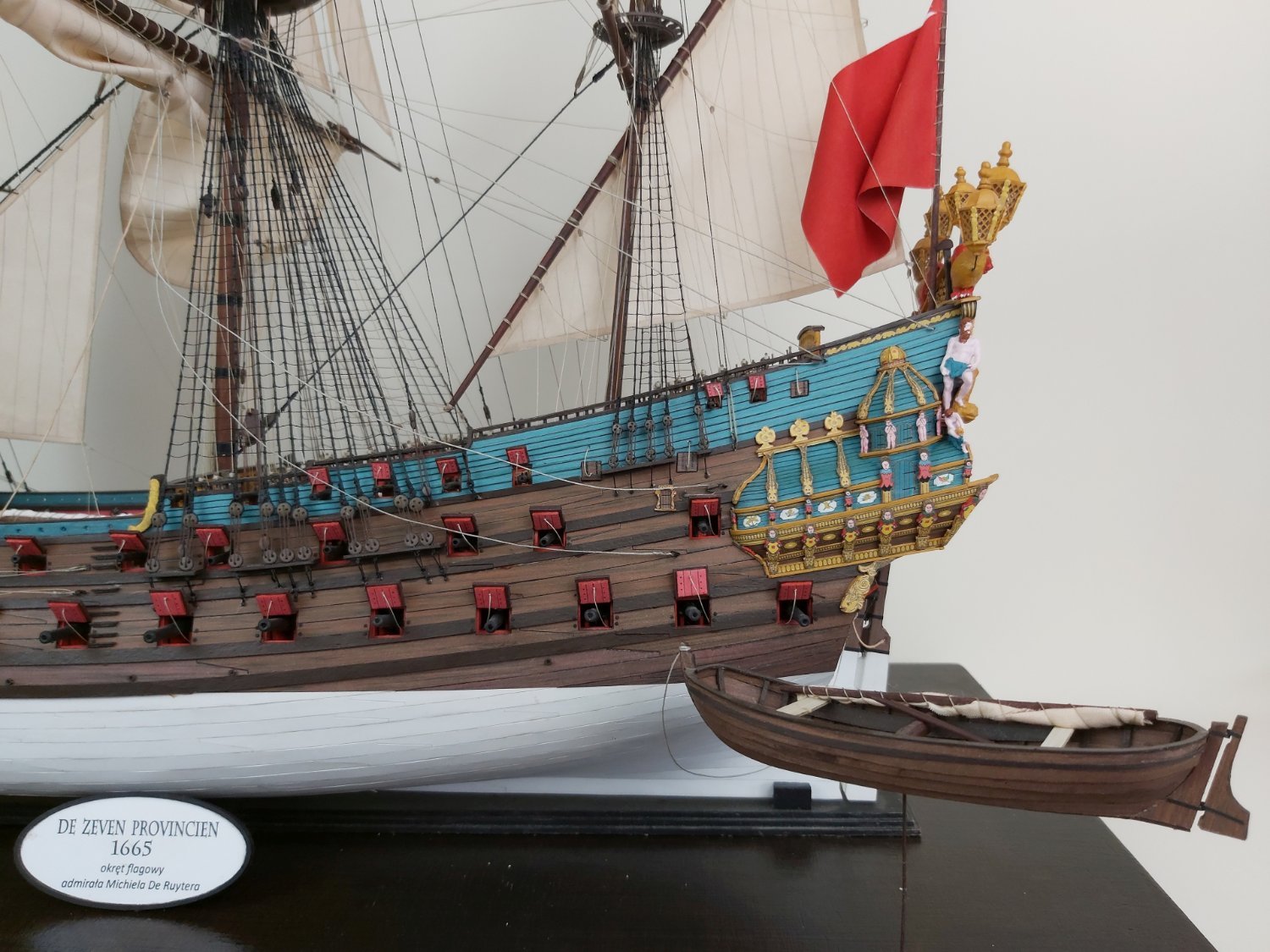
It remains to finish the work on the decorations: the designs of the sculptures were prepared by an external company (I do not have such skills myself) and after minor corrections they were printed and painted. All that's left to do is put a few dozen eyebolts in the decks and set the sloop amidships.
Some pictures:

Greetings
Tomek
-
Hi friends
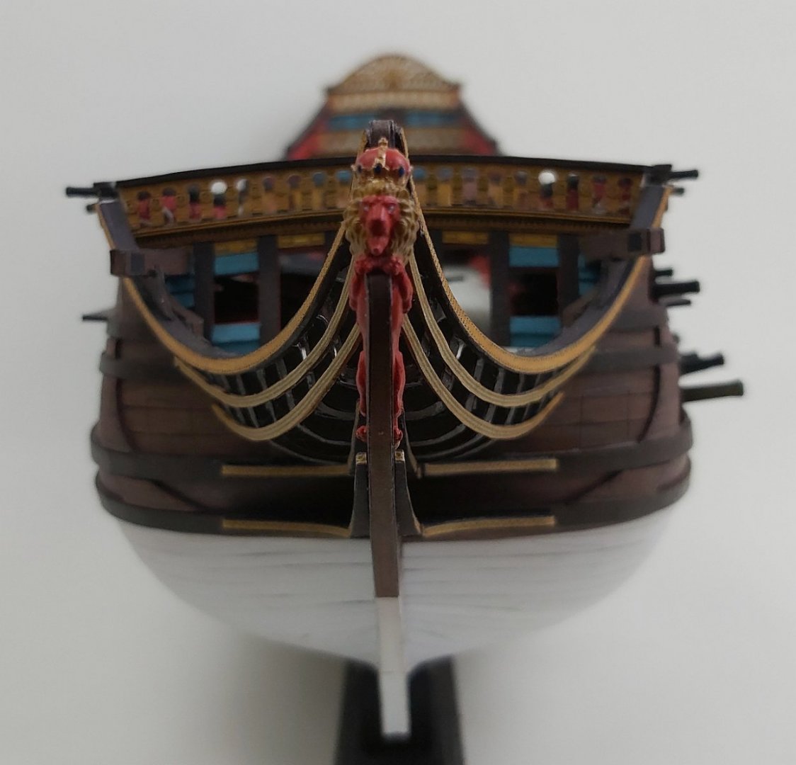
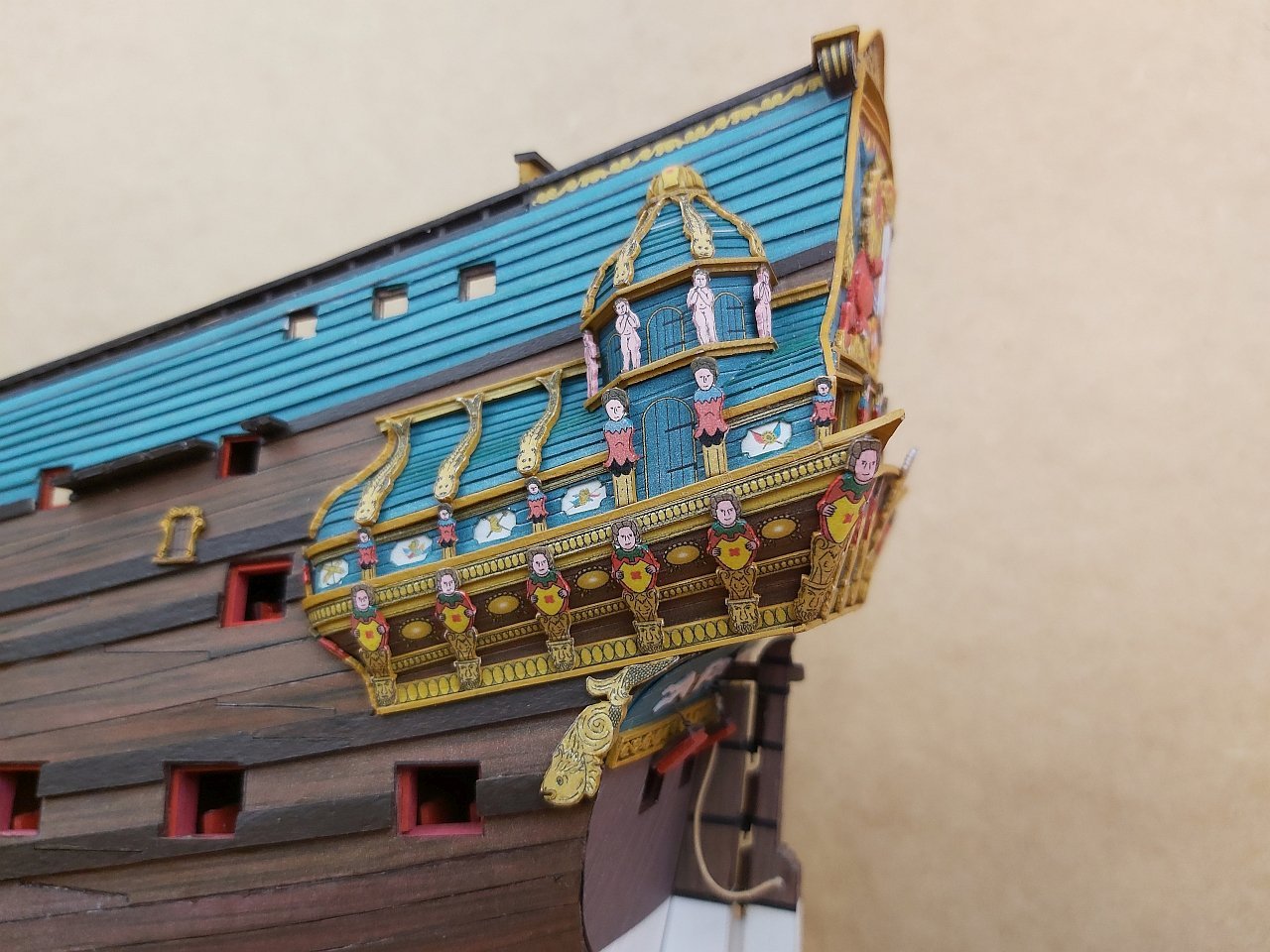
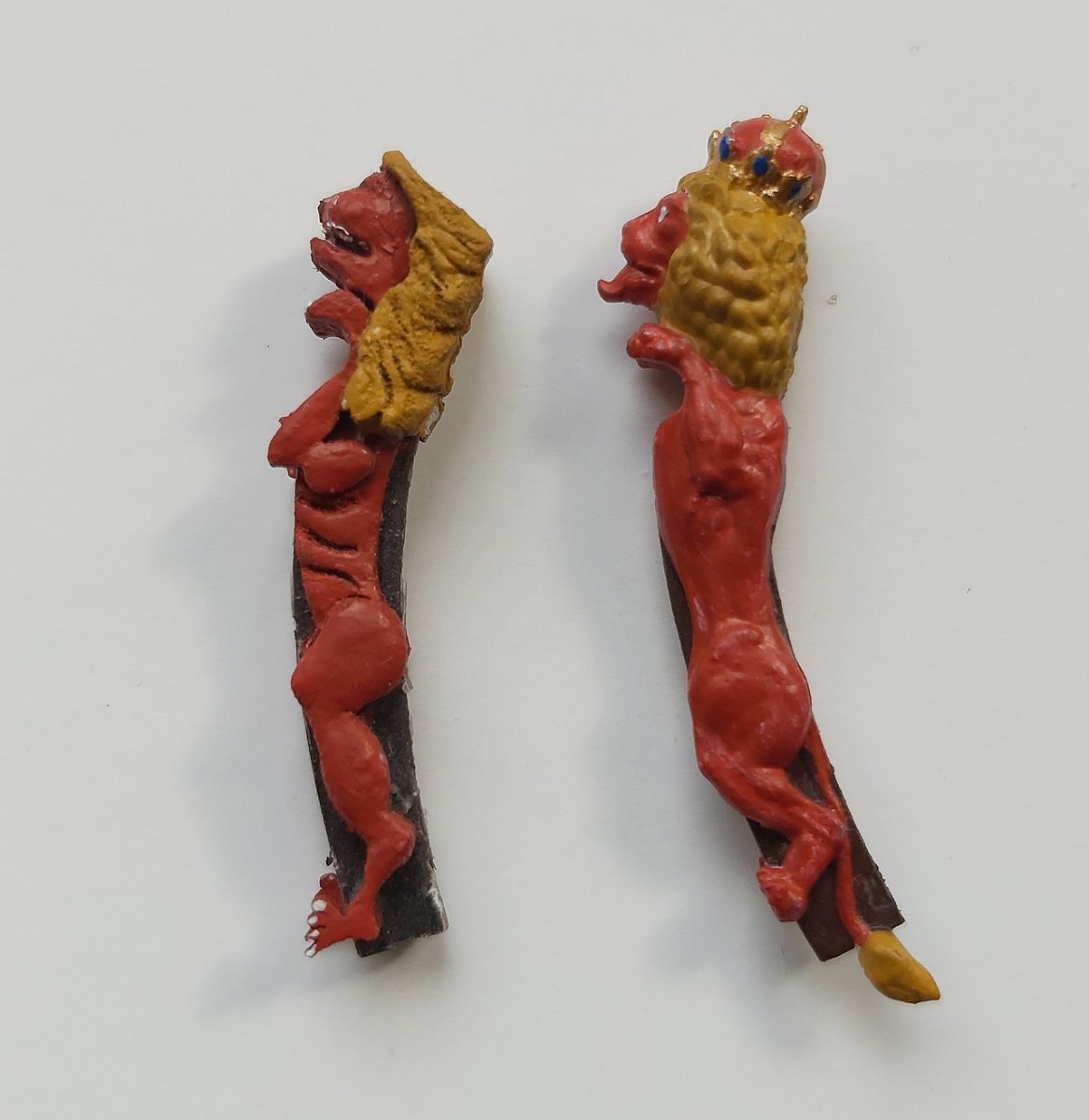
I must admit that I am not building the model at a dizzying pace, mainly because of the limited time and more and more details that need to be prepared and thought over. It took me a long time to make various attempts (mostly unsuccessful) to prepare the sculptures on the stern in the form of paper, which would slightly resemble THE SCULPTURES. The external company fulfilled the orders and I have all the sculptures ready for 3D printing, but those made of paper also had to be developed (because it is to be a cardboard model). This is what the first sample printed in resin looks like:
Therefore, I couldn't resist and replace the figurehead. Below is the old one of cardboard and the new one printed:

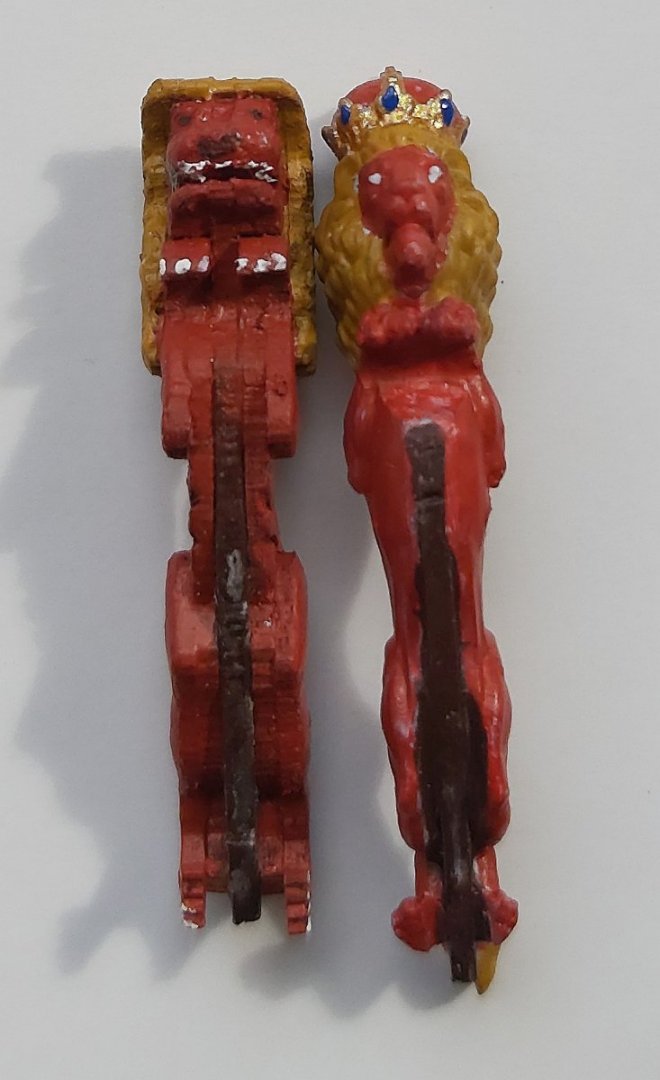
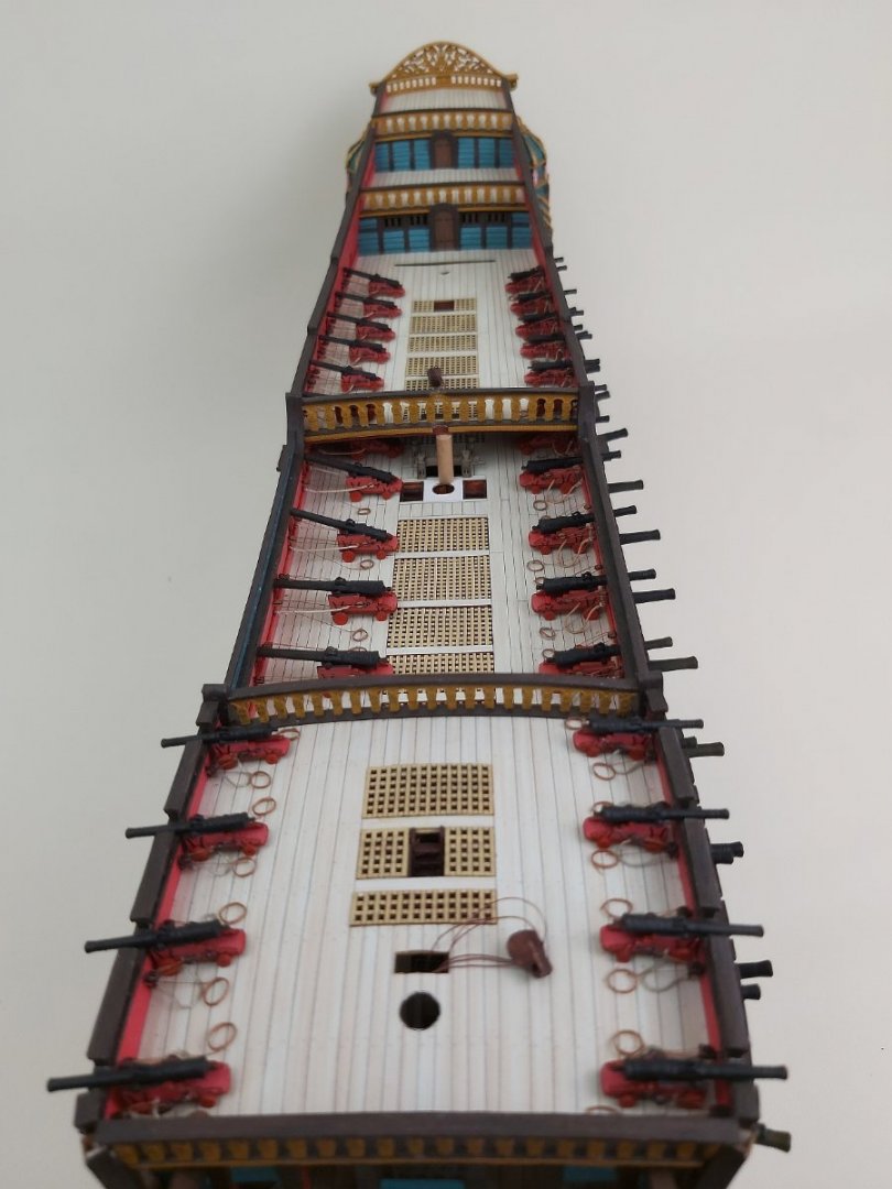
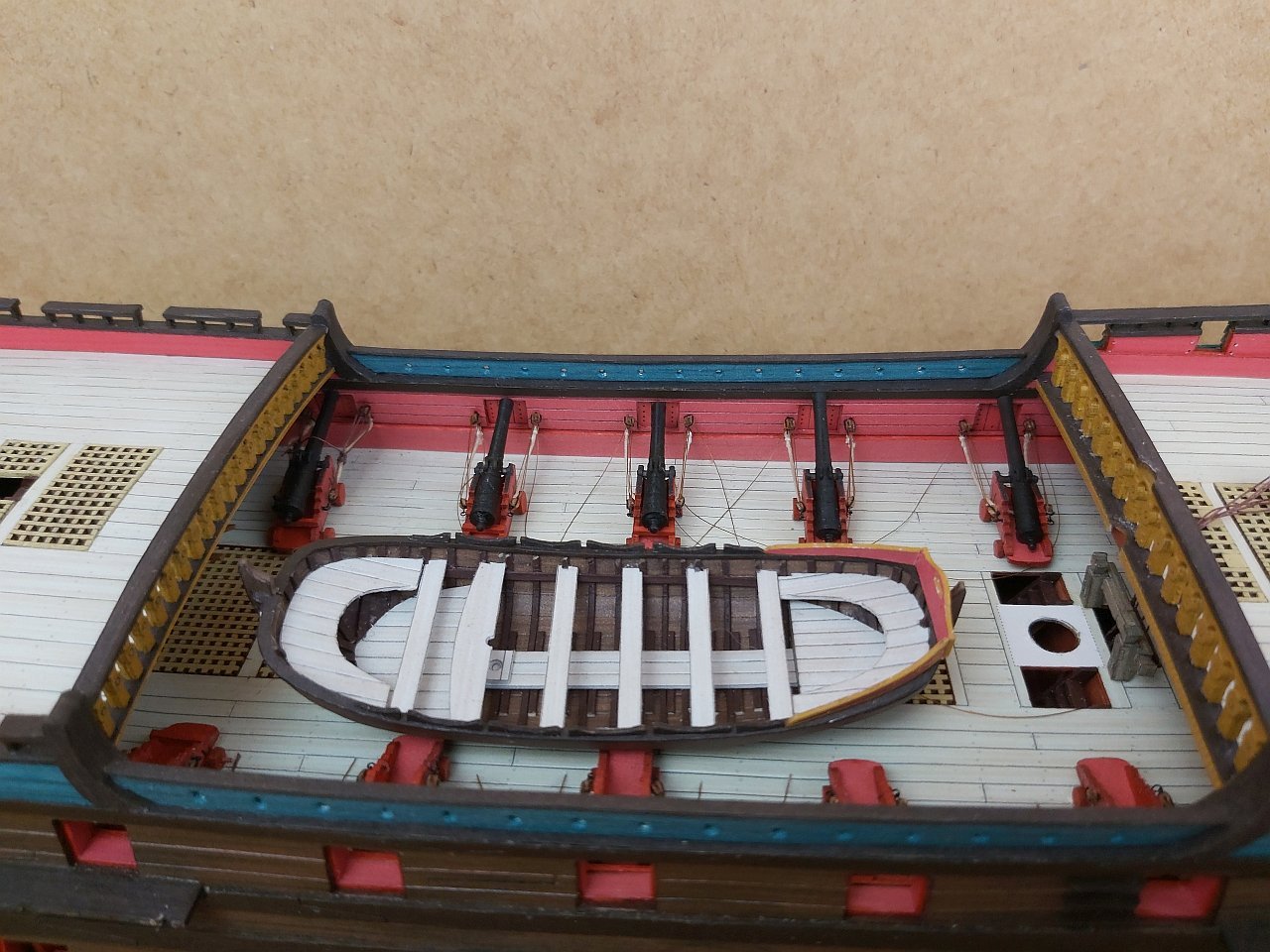
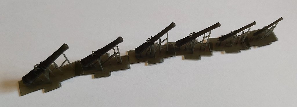
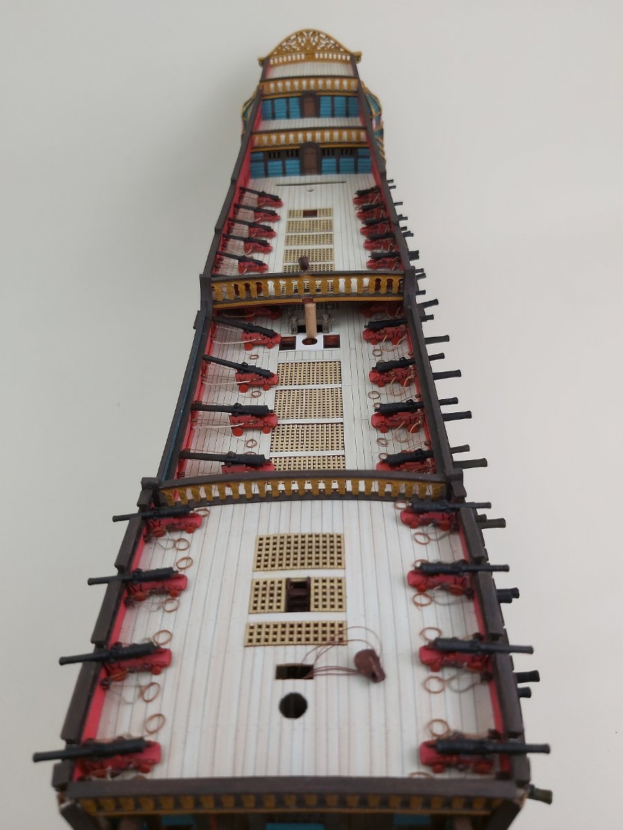
 In the meantime, I put the rest of the artillery on the decks. There was a lot of it, so I helped myself with ready-made gun barrels and 2mm 3D printed blocks.
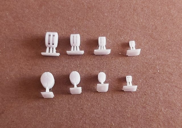
The print was gray, but the Vallejo primer sticks very tightly and nothing is peeling.
Now it's time to glue gunport lids, sculptures and lanterns, and all rigging "devices". Oh, and two more boats. I believe that in June I will start erecting masts 🙂
A few photos of an already armed ship:
 Best
BestTomek
-
2 hours ago, tkay11 said:
Thanks, Tomek. Very impressive use of software and design. I hadn't thought of using a CAD programme as I had forgotten the sides of the boat, being card, are solid rather than fully planked.
I asked because I am trying to build a 6 metre ship's boat at 1:96, and having difficulty in planking it properly. I was trying to think of other ways of doing it, including card.
Do you think having a 3D CAD programme is more helpful than a 2D one in preparing such a model? I can see that it helps in visualising, but does it help in constructing it?
Unfortunately Rhino is far too expensive for me, and I'd probably have to get a new graphics card as well.
Although I think I have to stick to 2D for the while, I'd be very interested in your thoughts on the value of a 3D programme.
Tony
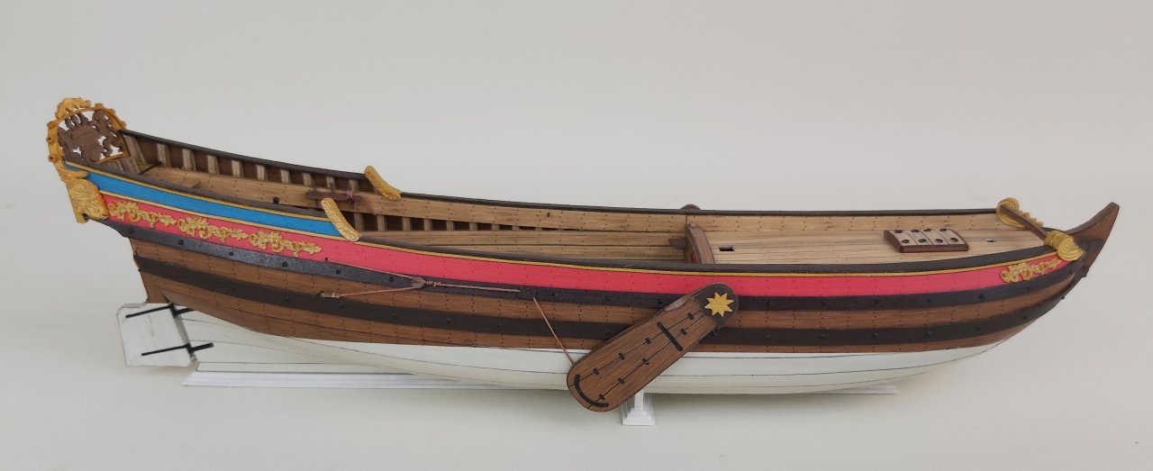
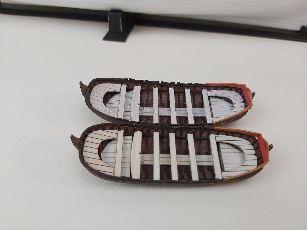
In fact, this boat has sides made of a single board. But I also designed boats with the typical layout of several boards per side.
I can only comment on Rhino because I work in this program. One of its functions (probably the most important for me in designing models) is the ability to unfold individual surfaces onto a plane, i.e. to obtain ready-made outlines of parts flat on cardboard (plywood/ wood).
The 3D design process itself takes some time, but the surfaces developed later have errors of 0.01mm, so they're perfect. That's why I use Rhino.You can take a look at the SketchUp program (free version available) that some designers use. There are rumored to be plugins on the web that allow the same feature of unfolding a surface to a plane. I haven't explored the topic, so I don't know much about SketchUp.
-
Well, it's rather simple work in paper/cardboard:
1. 3D drawing in Rhinoceros3D...
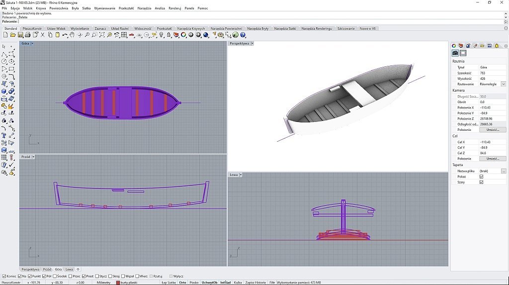
2. Parts developed in Rhinoceros 3D and colored in CorelDraw + Adobe Illustrator...
3. And a gluing instruction ...
I don't know if you expected such an answer. The gluing itself took about 1 hour. White cut edges need to be retouched with the appropriate color, which is obvious in cardboard models. The trick is to choose the right color.
Greetings
Tomek
- Meriadoc Brandybuck, mtaylor, tkay11 and 1 other
-
4
-
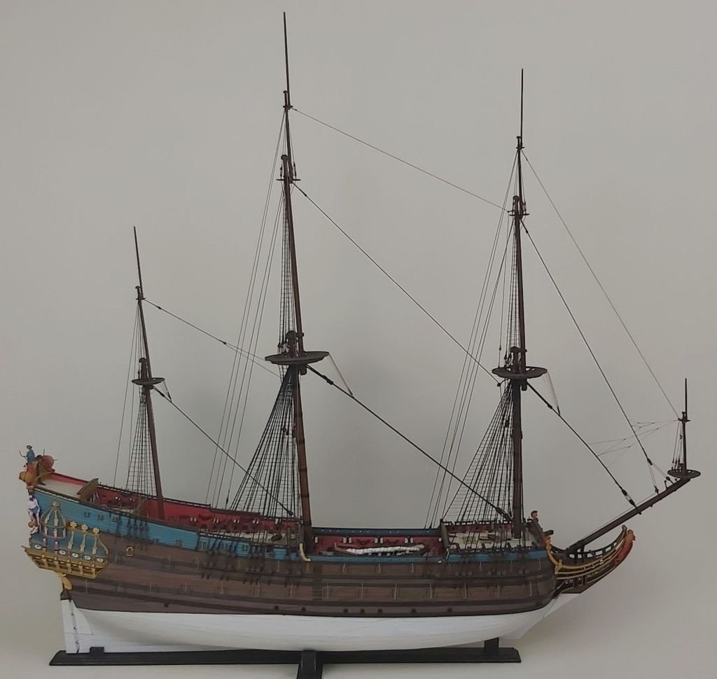
Hello everyone,
as is often the case in life, various circumstances prevented me from showing the finished model earlier, including the war in Ukraine (I live 100 km from the Ukrainian border). But the time has come to present the rest of the work on the boat.
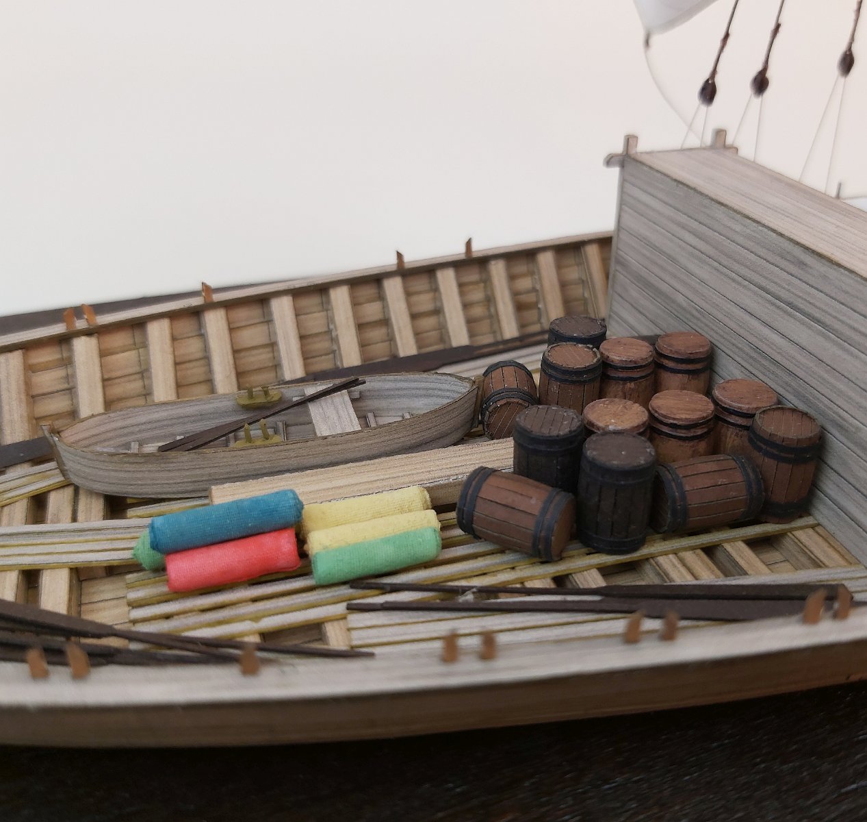
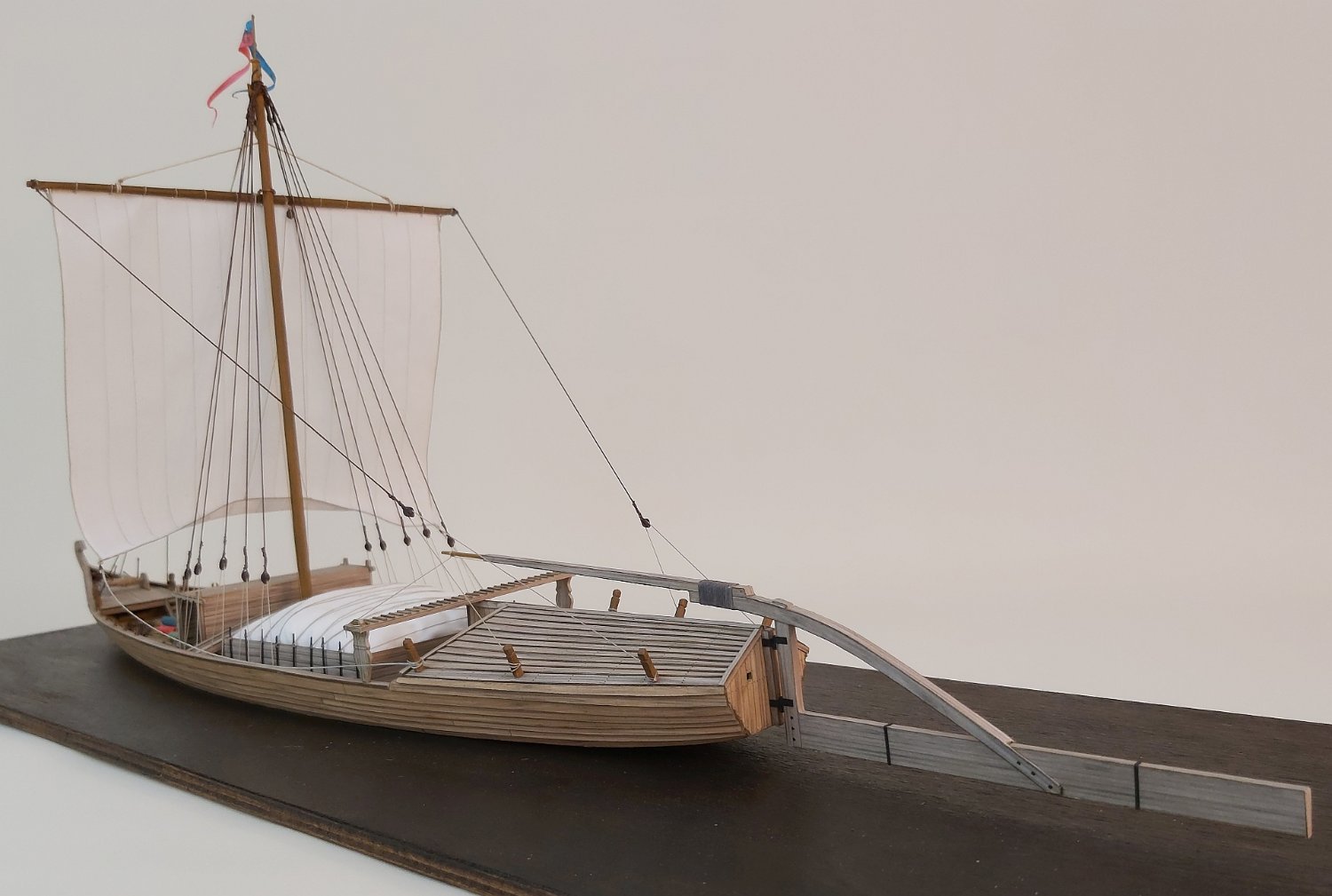
The very construction and making of individual parts was so trivial that it is difficult to write it in elaborations. As I treat this model as a test model, I decided to make a certain distortion, consisting in the fact that half of the ship goes to Gdańsk with grain and the other half goes up the Vistula with imported goods. This is because the rafting was carried out with the mast folded only with the help of oars, and during the return the mast was erected.
Since I had never done dioramas, so after many attempts to make grain in a scale of 1: 100, I gave up the idea and covered the entire cargo space with linen. I put barrels and bales of cloth in the bow part.
Laziness made itself felt when carrying out the rigging - the blocks are not made of cardboard (as would be recommended by the art of cardboard modeling), but of a 3D printer and painted.
Well, that's what I got out of this project.

Greetings
Tomek- Dziadeczek, tkay11, Harvey Golden and 11 others
-
12
-
 2
2
-
Thank you @wefalck @ for the hint. I don't know if it can be solved this way. This is because there was also a cargo space in front of the mast, and in the old drawings the amount of grain is piled high. Perhaps, however, I will use a block on the top of the mast, because at the end of the 18th century it would not be anything extraordinary.
As for the museum's publications, I don't think it has been translated.Greeting
Tomek
PS. Now I remembered there is a short summary in English in a few pages (11 pages)
-
@ Tony @ This is a direct print. I prepare a bitmap with a wood structure and if the boards / beams are straight, I simply "paste" them into the outline of a specific part. If the boards are curved, I deform the bitmap so that the grain pattern follows the shape of the part.
@ druxey @ I'm not sure, but it seems to me that as @ wefalck @ wrote, it was more of "pushing" the stern of the barge at the right angle and making the barge move much like a fish tail does. Due to the fact that the Vistula had (and still has shoals), the rudder blade could not be deeply submerged, hence perhaps longer. Quote of "Transformations in river boatbuilding in Poland"
... The control device was a combination oars and a hinged rudder with a very long rudder blade reaching half the length of the vessel ...
I, however, still cannot "decipher" the course of the halyard that was carrying the yard. In this powerful study "Transformation in river boatbuilding in Poland", published by the Maritime Museum, it is stated that the yard was raised with the help of a winch placed on a small bow deck. At the same time, in quite old plans from 35 years ago there is no mention of any block placed on the top of the mast and the halyard only passes through the sheave in the mast.
Hence my doubts: lifting such a heavy yard and securing the halyard only to the cleat at the mast seems unlikely to me. It would be more sensible to use a windlass, but that would require a block in front of the mast. Maybe there is another way?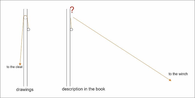
Tomek
- GrandpaPhil, mtaylor, tkay11 and 4 others
-
7
-
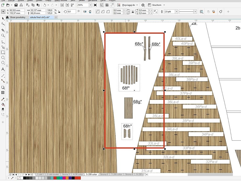
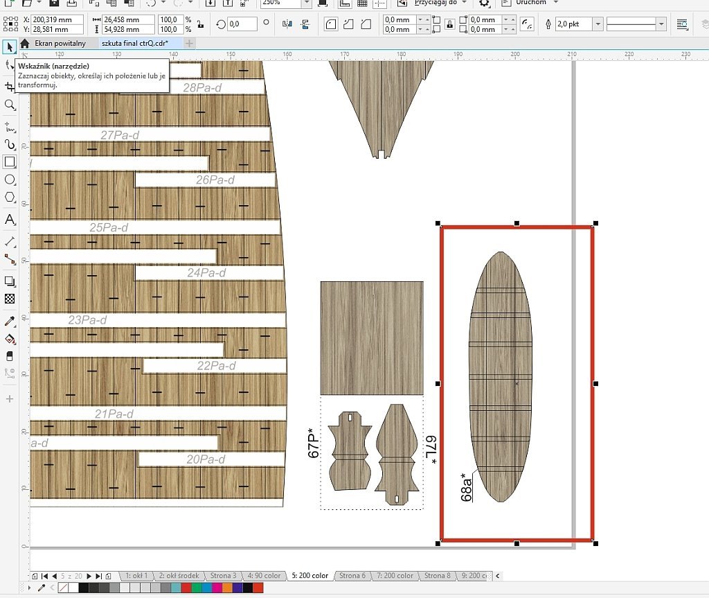
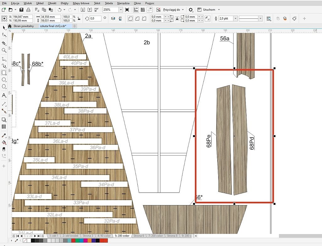
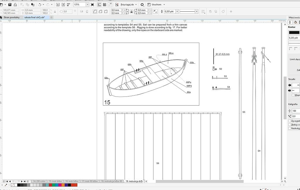
Hello
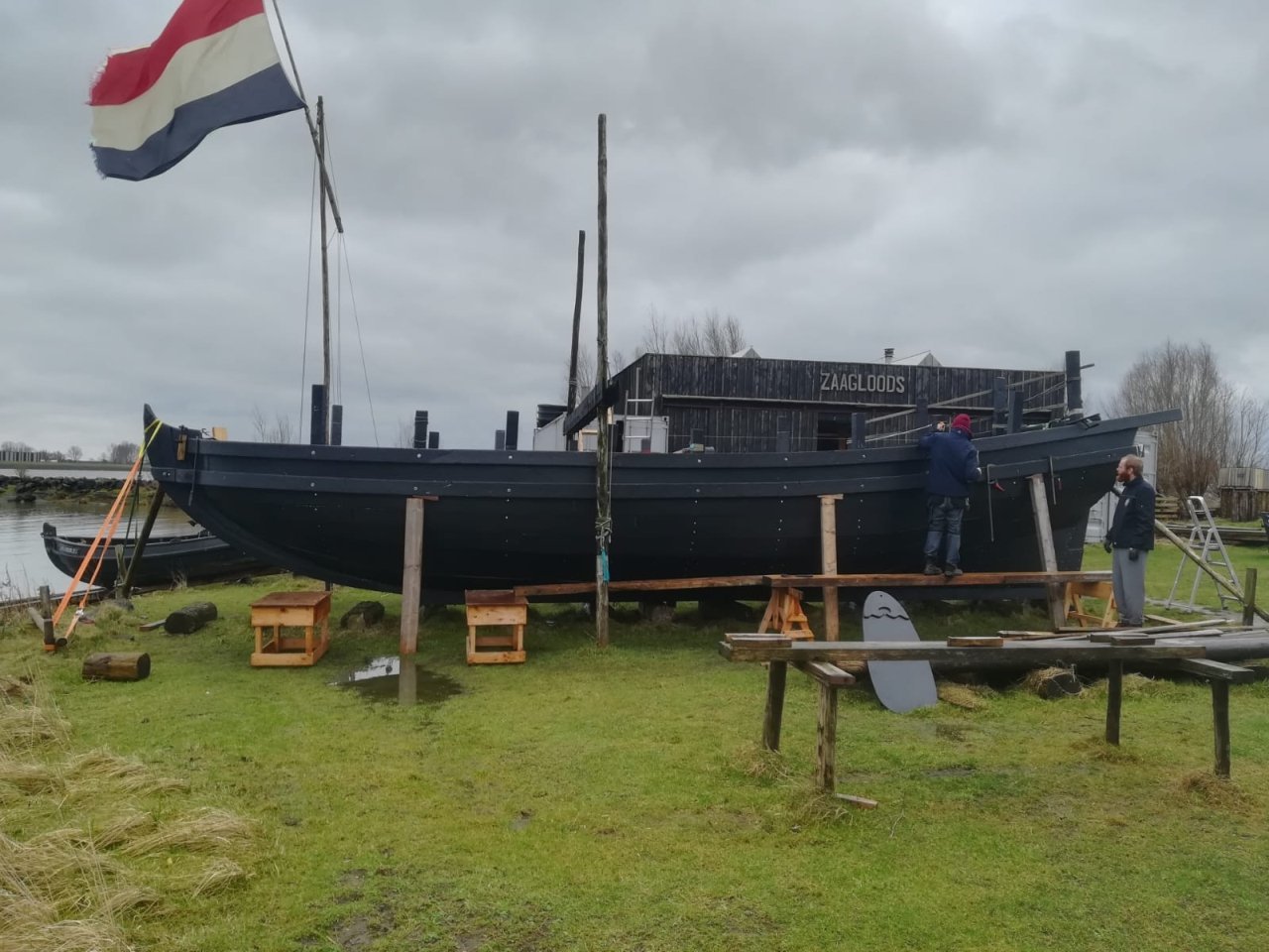
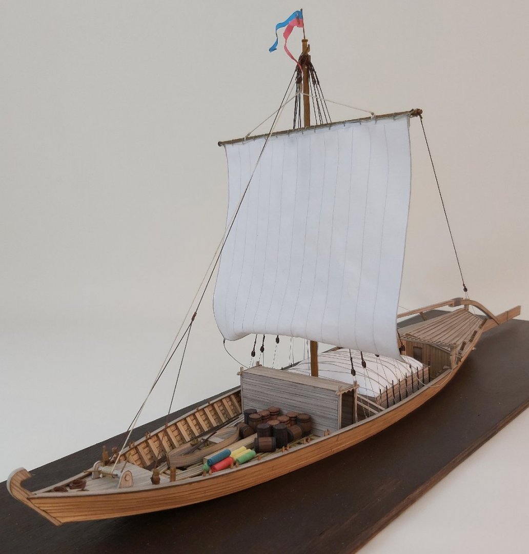
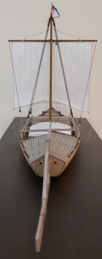
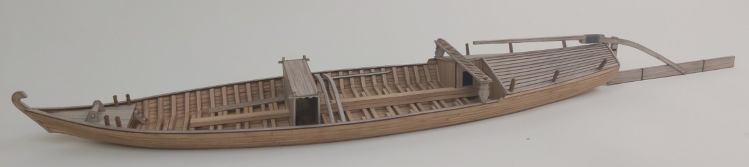
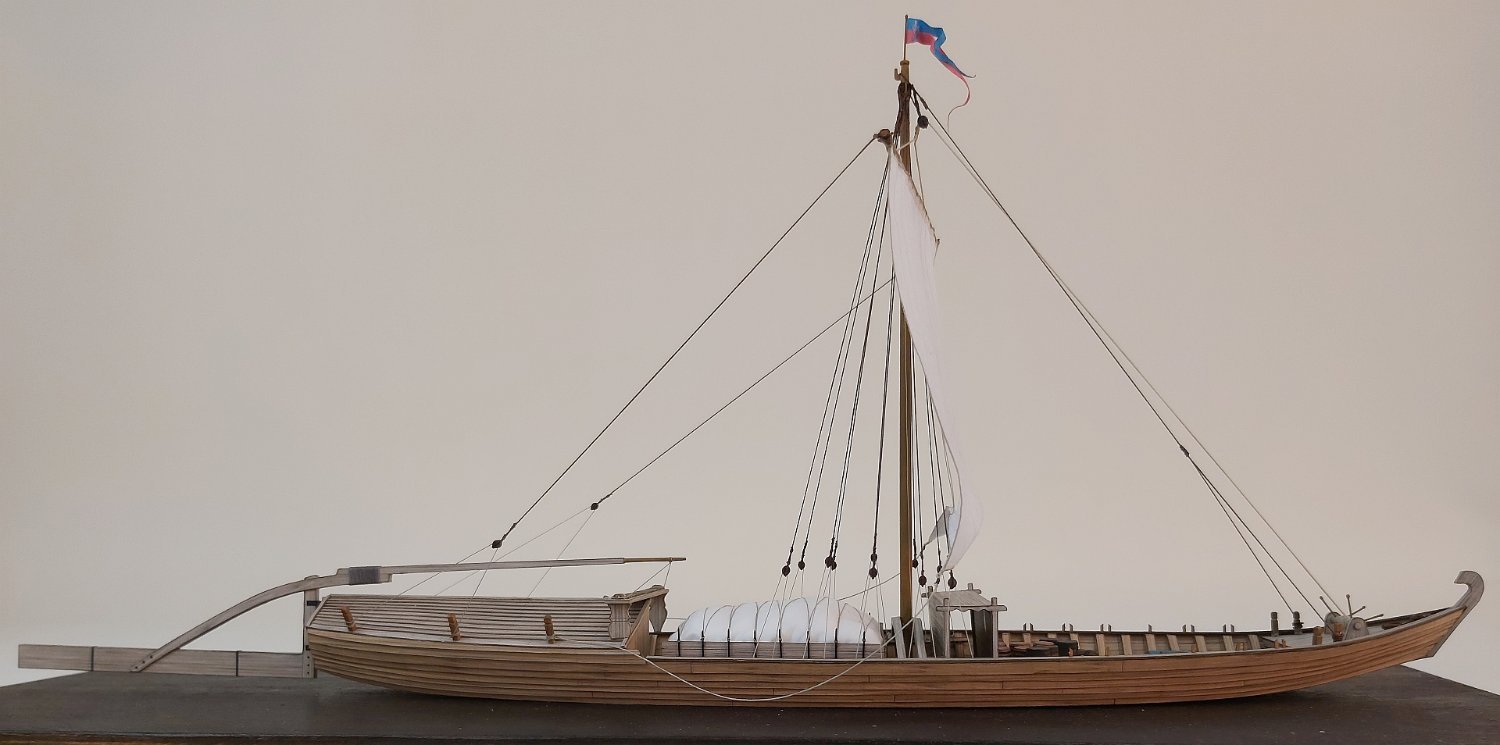
Waiting for the cooperators until they meet what they promised for my "7 Provinces" I decided to rest for a while and started something simpler (but not much smaller).
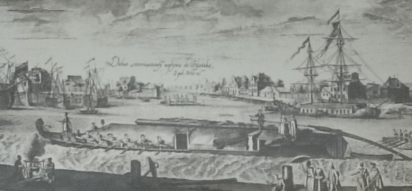
The "szkutas" sailed on the Vistula for several centuries, transporting mainly grain to Gdańsk. They were really huge, because the hull itself was even 30 meters long, and at the rear there was also a characteristic long rudder blade.
Below is a painting by Bernardo Bellotto called. Canaletto with the barge and the panorama of Warsaw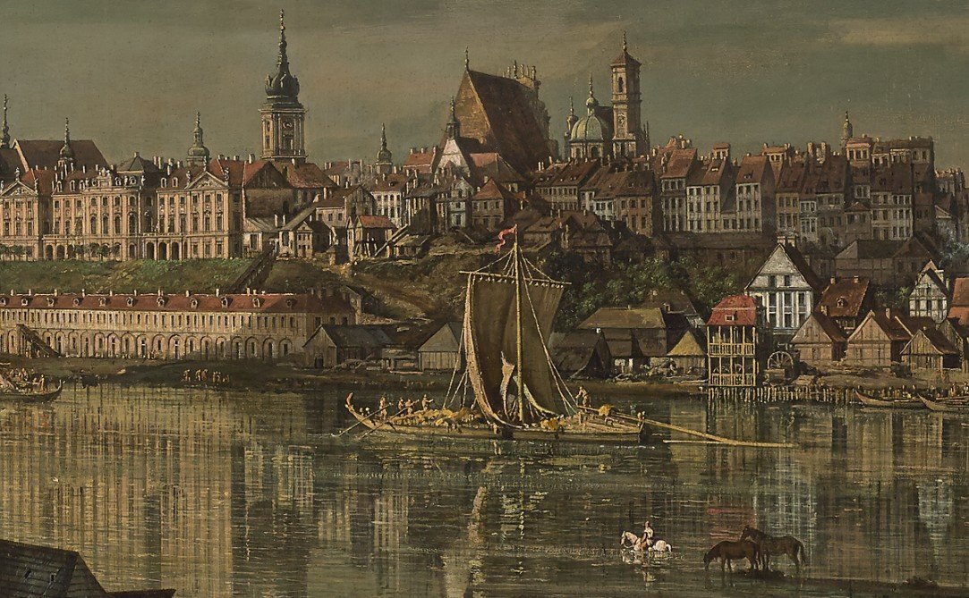
(by the way, Canaletto was the court painter of King Stanisław August Poniatowski and his paintings depicting the architecture of Warsaw at that time were used after the Second World War to rebuild the Old Town of Warsaw)[public domain]Fortunately, archaeological sites were discovered and secured in many places in Poland, hence more and more is known about old Polish river ships.
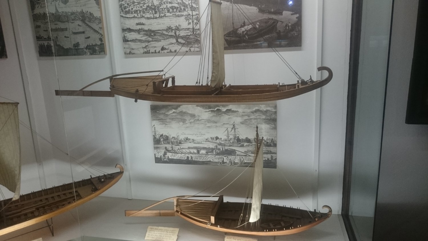
In addition to the szkuta there were smaller vessels sailed: dubases, kozas (goats), byks (bulls), galaras, komięgas and the smallest rafts. The smaller ones did not even return from Gdańsk and were sold for wood. Models of these ships (boats) can be seen at the Maritime Museum in Gdańsk.
Historically, the shipping of goods (grain, leather, wood) down the Vistula to Gdańsk was a very important branch of economic development for Poland. Sometimes it was said that "Poland was the breadbasket of Europe" due to the export of huge amounts of grain.
And I also have a certain "relationship" with Polish rafting, because I live in the Ulanów region, which is called "the capital of Polish rafting". The San River flowing through Ulanów goes into the Vistula and was the main route for transporting goods from the Zamość region (the name Zamojszczyzna and the city of Zamość are associated with one of the largest magnate families in the history of Poland - the Zamoyski family).
A phenomenal document describing the construction of these boats is the preserved inventory with precise measurements made in 1796 in the river port in Krzeszów (9 km from my home!!!) by the Austro-Hungarian engineer Benevenutus Losa von Losennau.
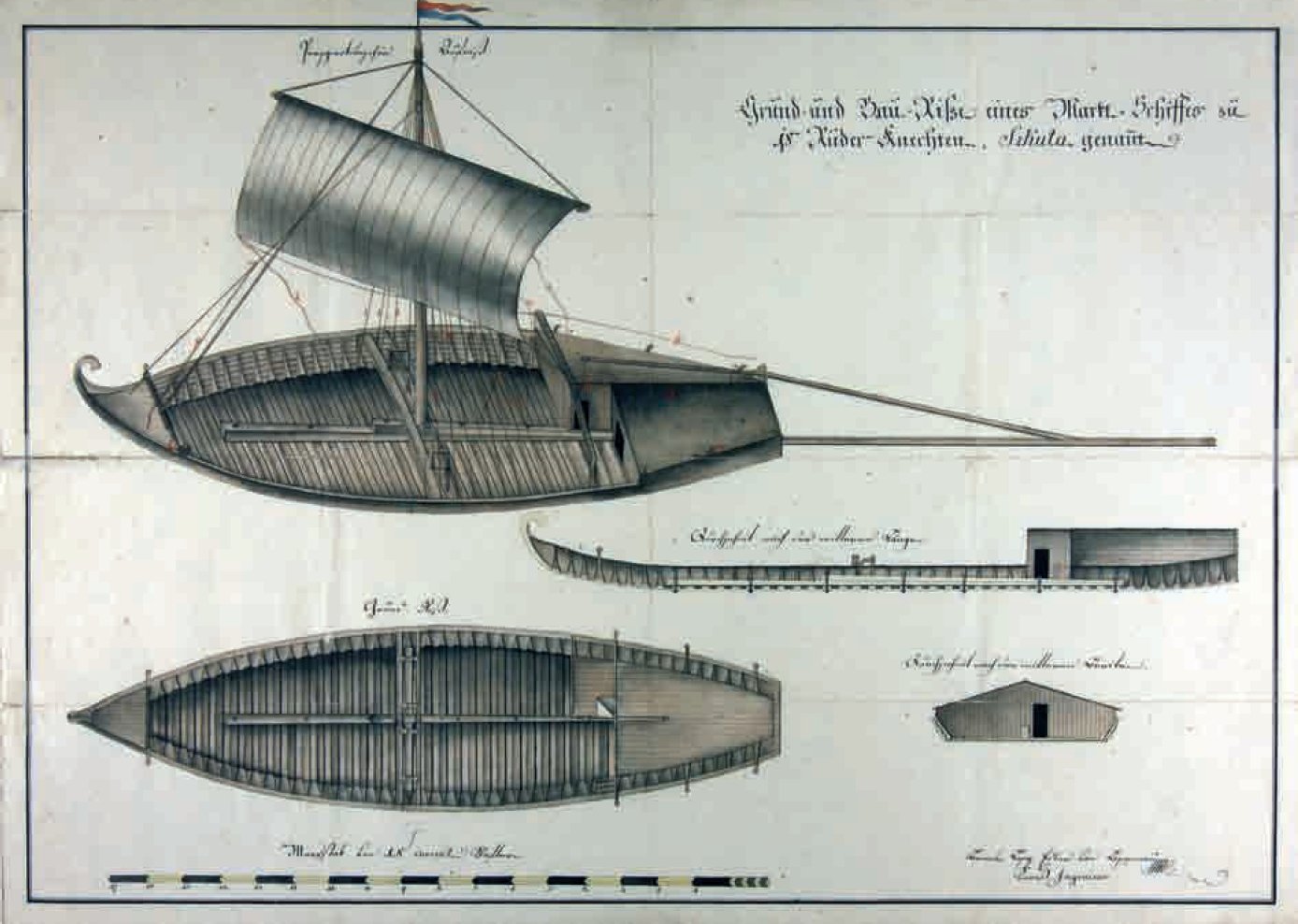
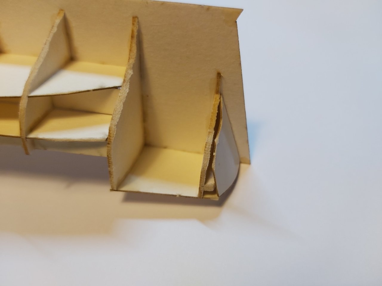
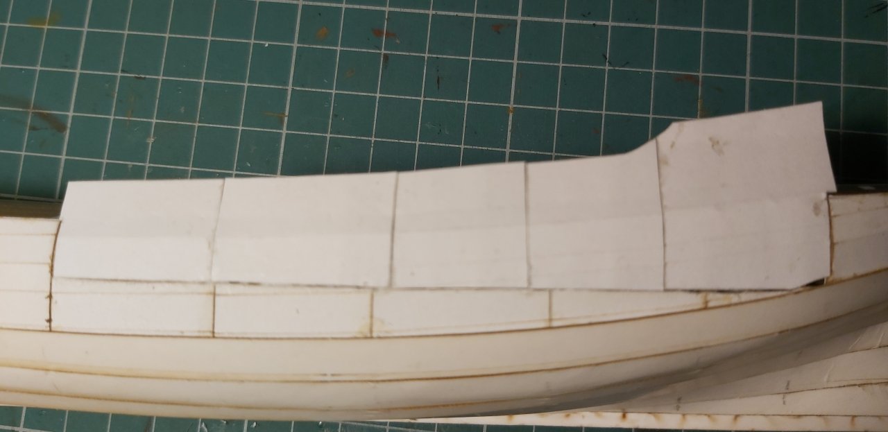
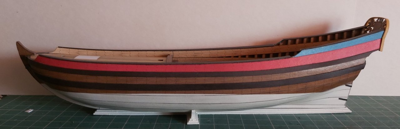
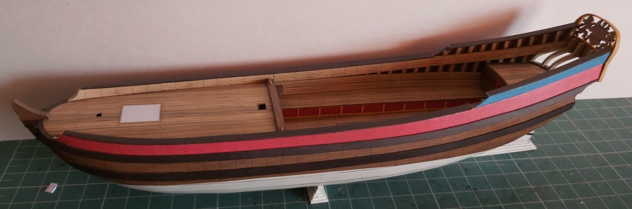
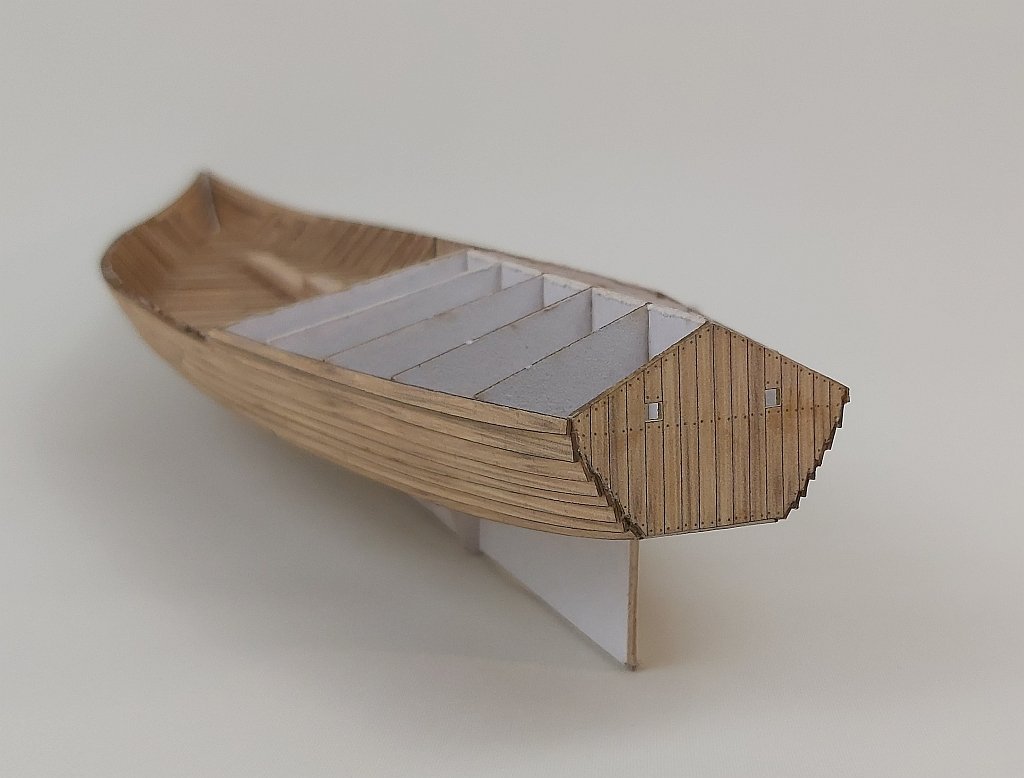
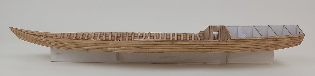
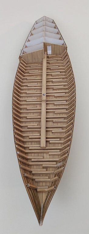
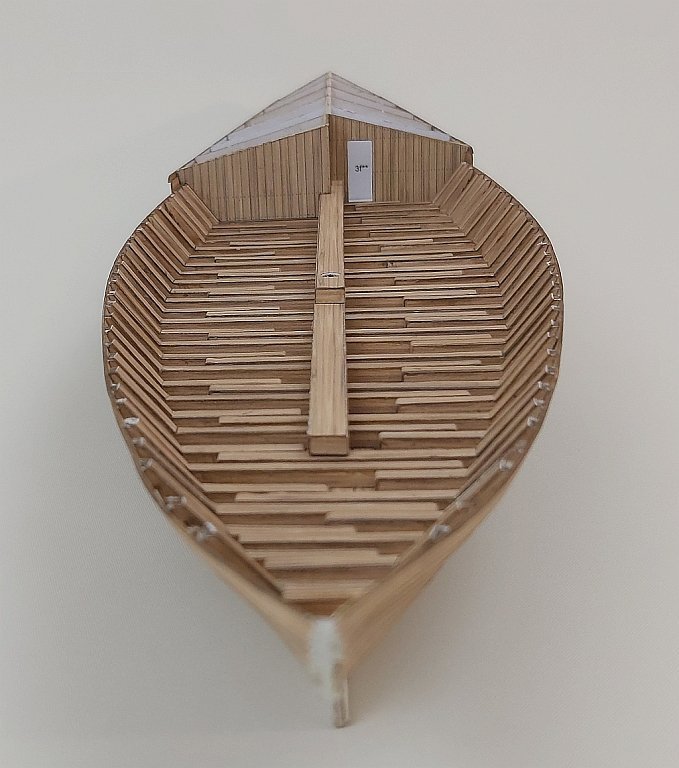
The szkutas had a flat bottom slightly raised at the stern and the bow made of pine, oak sides "overlapping", one square sail. At the stern there was a storage and utility room. The rudder blade, up to 12 meters long, with a very long tiller, which was operated on a high transverse platform, was very characteristic.
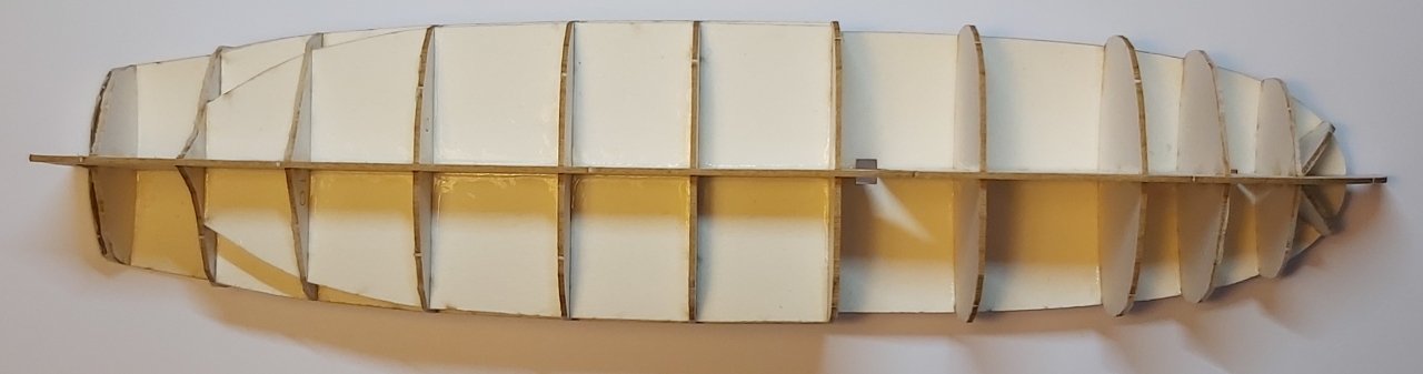
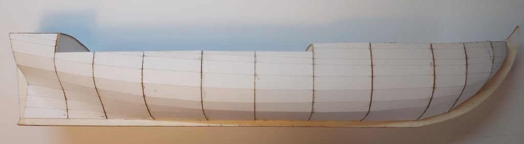
Well, the construction of the model is so trivial that I took almost no photos:
1) 0.5mm flat cardboard bottom
2) glued frame of the room at the stern
3) the first plank stuck to the edge of the bottom
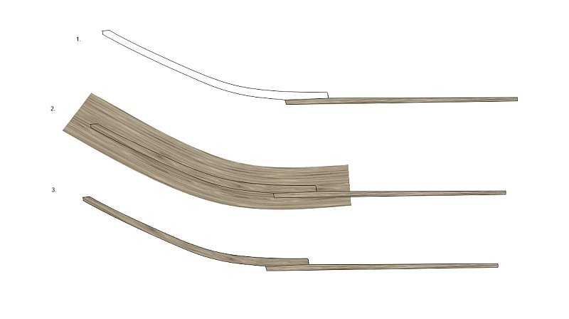
4) 60 brackets......what caused some problems. I started gluing them empty inside. Unfortunately, despite the care taken to make them precisely, they came out very differently. Even worse was that they turned out to be too flaccid and there would be no way to stick the planks to them later. Fortunately, after the first few pieces, I started making them in the form of three cardboard layers glued together (2x1.00 mm + 0.50 mm).
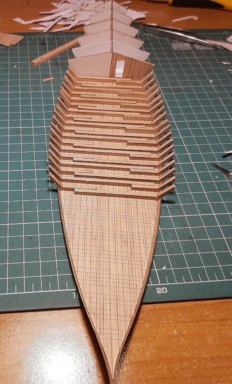
Then I have attached the rest of planks to this construction.
Greetings
Tomek -
On 10/20/2021 at 8:37 PM, CDW said:
A copy of a 1:1 Barrett? I would be interested in the original of that kit.
A cardboard weapon in a 1: 1 scale is the specialty of a modeler from Poland, Jarek Rokita. You can see his work on FB at "Kartonowy Arsenał Broni". Incredible that everything is made of cardboard.
Tom- catopower, Keith Black, mtaylor and 2 others
-
5
-
You've built this model wonderfully. Top class. Congratulations.
Tomek
- popeye the sailor, Egilman, Canute and 5 others
-
8
-
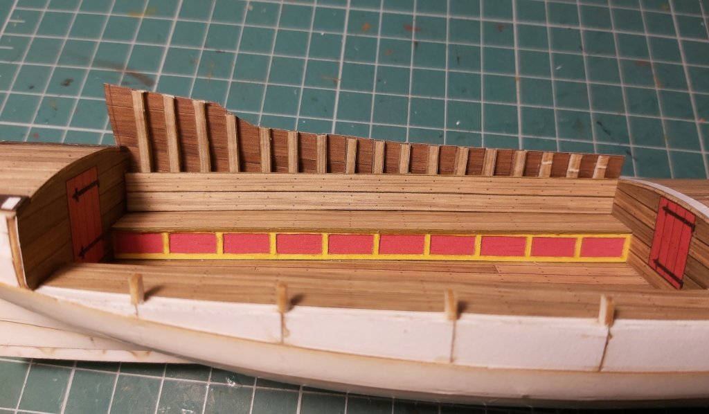
Hello everyone,
Recently, I haven't had much time to continue building, so progress has been slow as well. Bakdek already has gretings, I set up the artillery amidships and tried on the sloop, which is 1 meter too big, so I will have to build it again
After many attempts, I decided to make bas-reliefs in the simplest form, i.e. scratches glued on a thicker cardboard. Looking at the effect, it seems that all of them had to be stuck to 1.0 mm cardboard, because some of them are too "thin". I will add additional layers of paper to them in some places to make them more three-dimensional. And one of the friends will improve the colors, add some shadows, so they should finally look better. Unfortunately, I am not a painter:-(((
I chose this form for ornaments because I anticipate that the model will appear as a kity, and therefore the difficulty level must be accessible to intermediate cardboard modellers. Anyone who has skills will surely make these decorations on their own from wood, modeling masses, green stuff, etc.
The largest sculptures, which are not there yet, will be made of several parts (if I can design it), and as a last resort, I ordered a design prepared for 3D printing. Time will show which solution is the best. Currently, the stern looks like this:
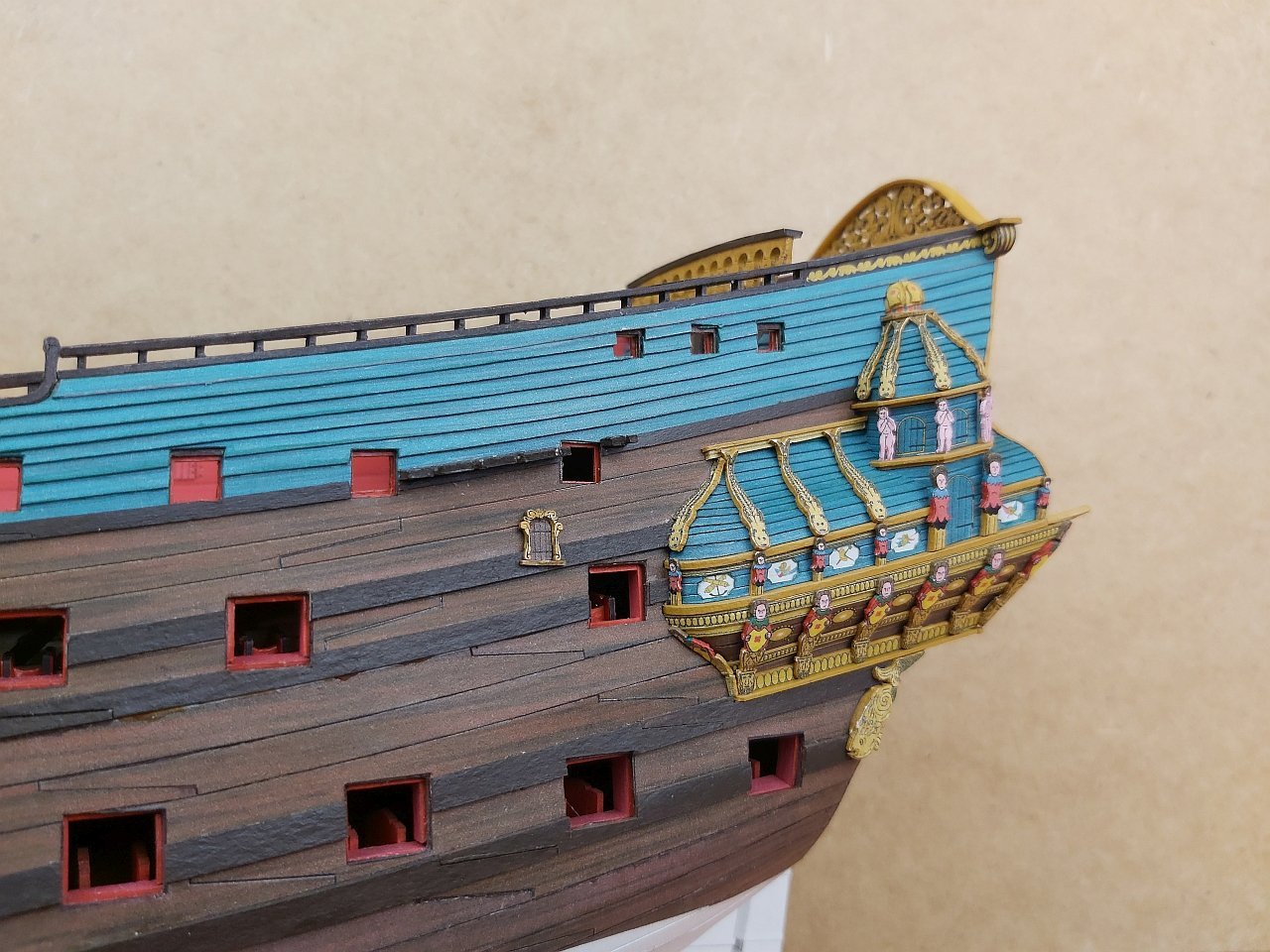
All comments will be appreciated.
Tomek
-
16 hours ago, ccoyle said:
@0Seahorse might know the answer. Tomek, what do you guys call the material that is used for laser-cut frames in card model kits? The closest thing I can come up with in English is mat board, but I don't that is actually what it is.
The popular name in Poland is "birmata" (beermat), because it is used to make colorful coasters for beer mugs. There are certainly many manufacturers and the available thicknesses are from 0.75 to even 3 mm. Here is an example of the Finnish producer Pankakoski Mill Oy, and this type of cardboard is "PankaDisc". There is even a specification in PDF.
https://www.pankaboard.com/categories/specialities/
Greetings
TomekPS. By the way, great job! The Cardboard Collection (and its owner / designer Paweł Mistewicz) are currently considered the best designed and "glueable" cardboard airplane models in Poland.
-
Hello,
Thank you for your comments and opinions.
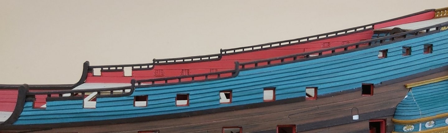
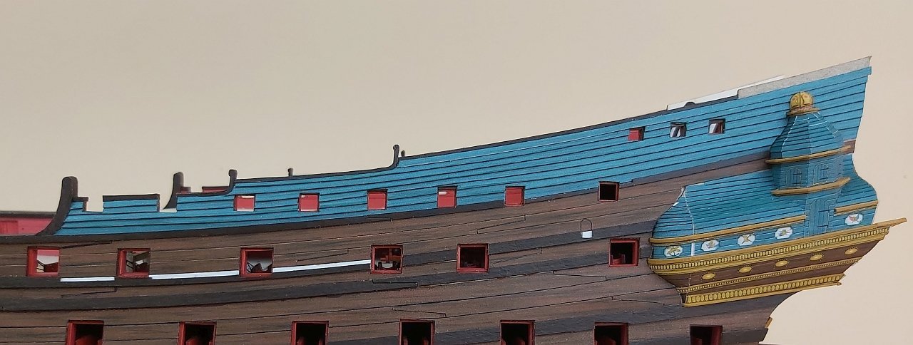
There was a long break in updating my work on "De Zeven Provincien" again, because I wanted to "close" the hull and stop it from hitting my eyes with white "spots" of unfinished fragments. In a way it worked 🙂
All handrails and decorative slants have been laser cut / engraved and painted yellow ocher.
The construction was slowed down by my reluctance to make a dozen or so cannon barrels out of paper. To solve the problem ... the laziness problem ... I printed the barrels in resin.
... and the building process started right away. It took the longest time to build the head and bow deck, but I'm happy with the results.
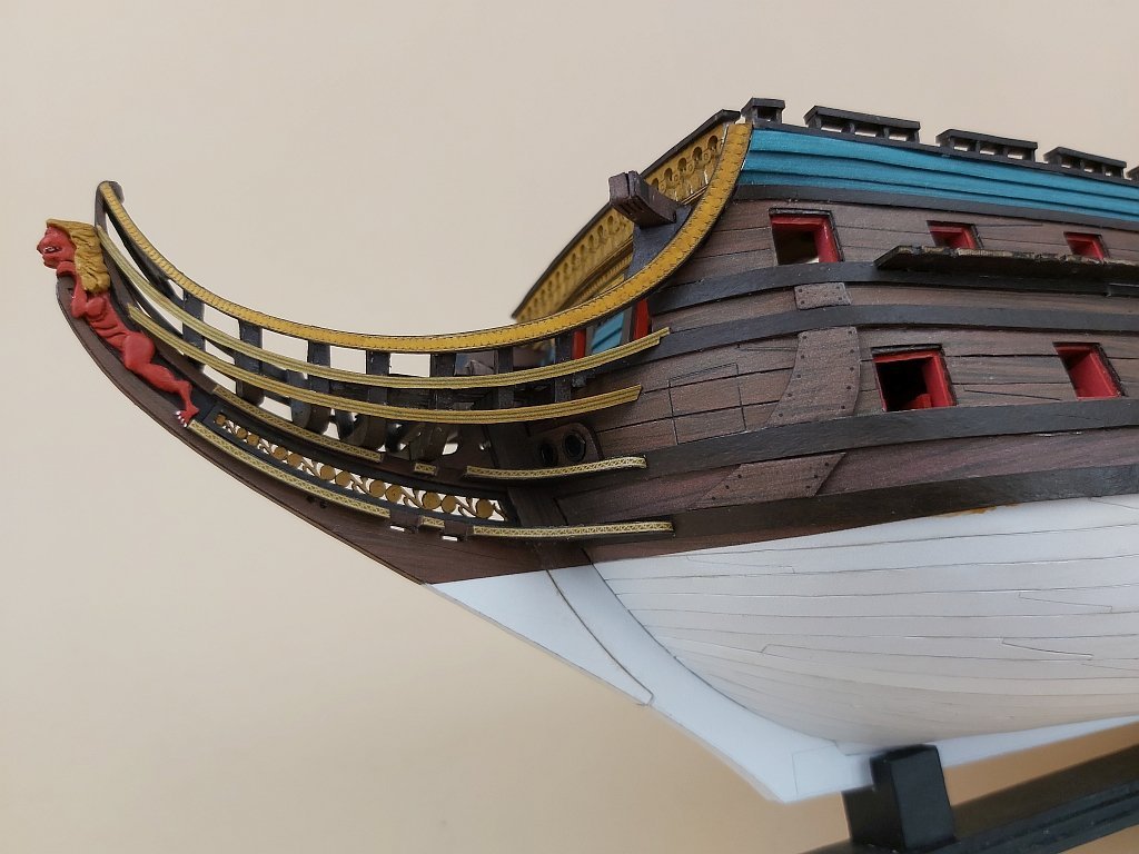
Now it is time to add artillery on the decks and decorate the hull with dozens of sculptures 🙂
Regards
Tomek -
And again a little update.
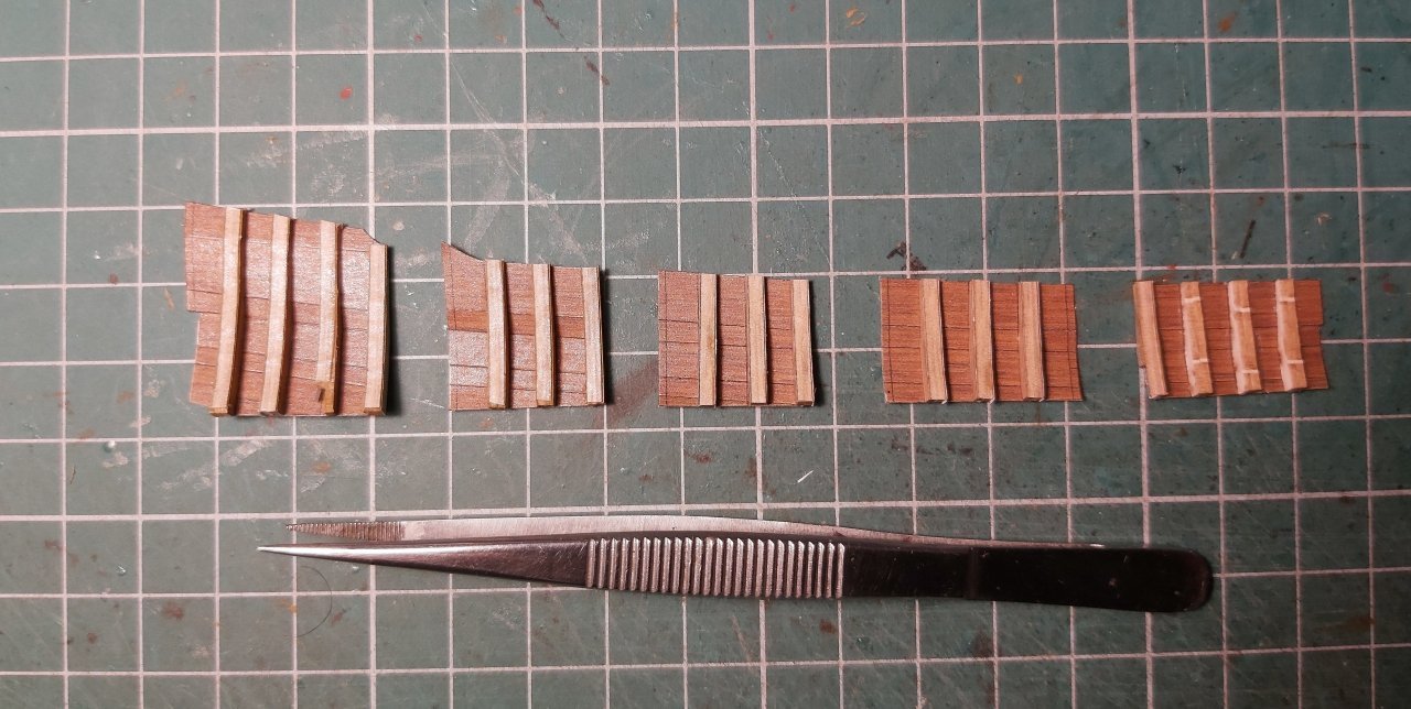
At this stage, I have always had a problem with handrails with a lot of posts, which are difficult to prepare to be identical and fit. So this time I made them in the form of 1 mm thick "combs" glued in pairs, to which I glued 0.5 mm thick strips at the upper edge and masked the whole thing from the top with a 3 mm wide strip. To make it more understandable, below is a piece of such a handrail and the effect in the photo.
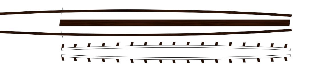
A much stronger solution. And how long does it take to cut these combs out of 1mm cardboard? I don't know, because I cut it with a laser 🙂 But if you think about cutting many posts to the right size and giving them appropriate bevels at the ends, the workload may be comparable.
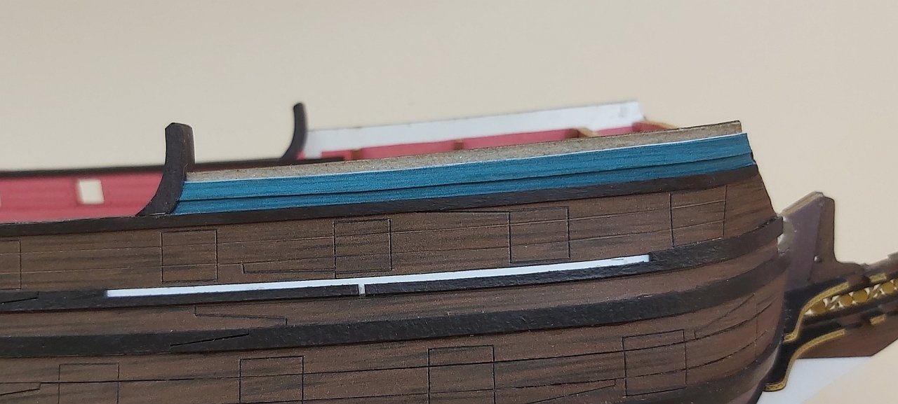
Another batch of boards appeared on previously prepared bulkheads. Unfortunately, I did not retouch the side edges of each board (they were supposed to "hide" between the beams) and you can see some white spots. I hope that the carvings will hide it a bit and "soften" it.
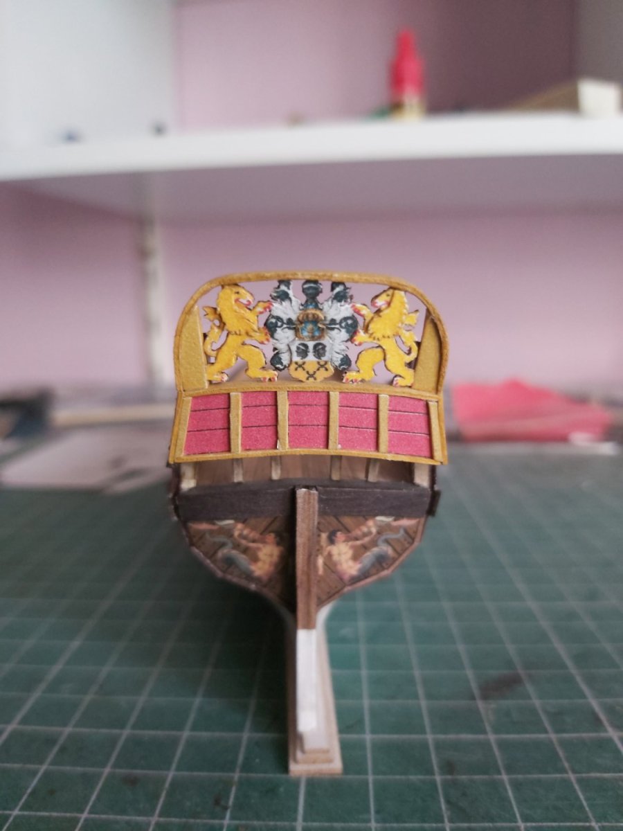
The time has finally come to close the stern. From two layers, I prepared the entire bas-relief and glued it to the taffrail (asymmetrical - I know, but it will stay that way). On the edges, I glued thin strips (0.5 x 1.0 mm) to mask any inaccuracies. And just like with the side handrails, I also made the stern one in the form of a "comb", additionally engraving a small pattern. I am always afraid at this stage that all dimensions have been lost, and here is a real surprise: the laser-cut aft handrail fit literally without any adjustments. Finally, there are the horizontal protruding ends of this aft handrail, and this is how she looks today:

Greetings
Tomek -
Hi,
I finished up the planking and "closed" it with the rails (of course it's just the lower part of the handrail), which I ambitiously made in a printed standard without painting them. There is some "pecking" and dugout, but it was worth it.
The upper planking made with an overlap planks was supposed to be easy, but it took a lot of time (try-on - retouch - slow sticking). The "boards" are 0.4 mm thick, as it seemed reasonable (so that it was not a thin cardboard and and that the edges are visible), but if you add inaccuracies, the thickness of the glue and other small mistakes, it was probably better to make it from cardboard 0,3 mm. Anyway, it is already stuck and I will not tear it off. I missed retouching in a few places, but it can be fixed.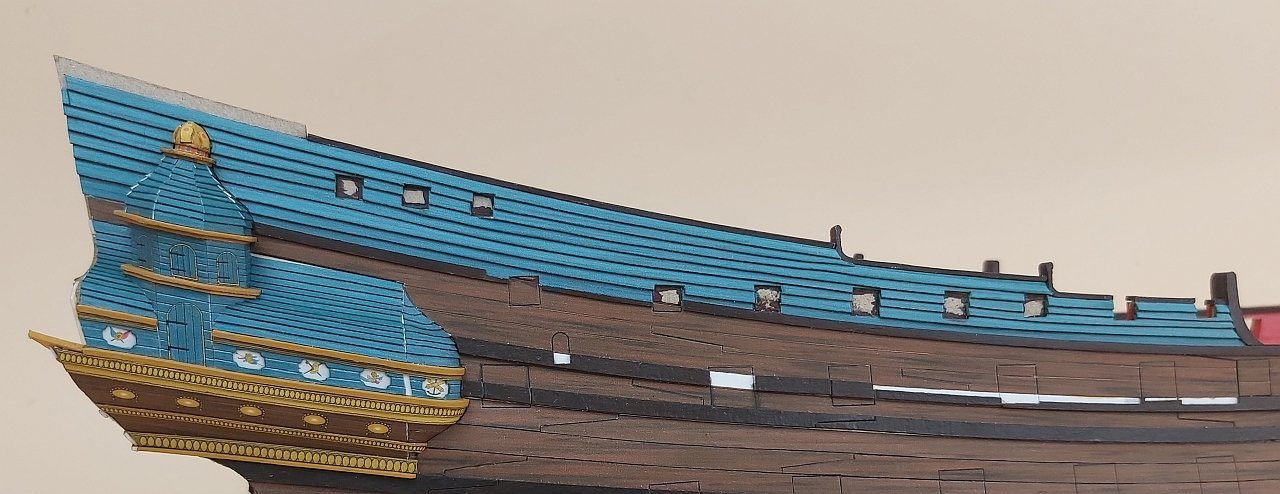
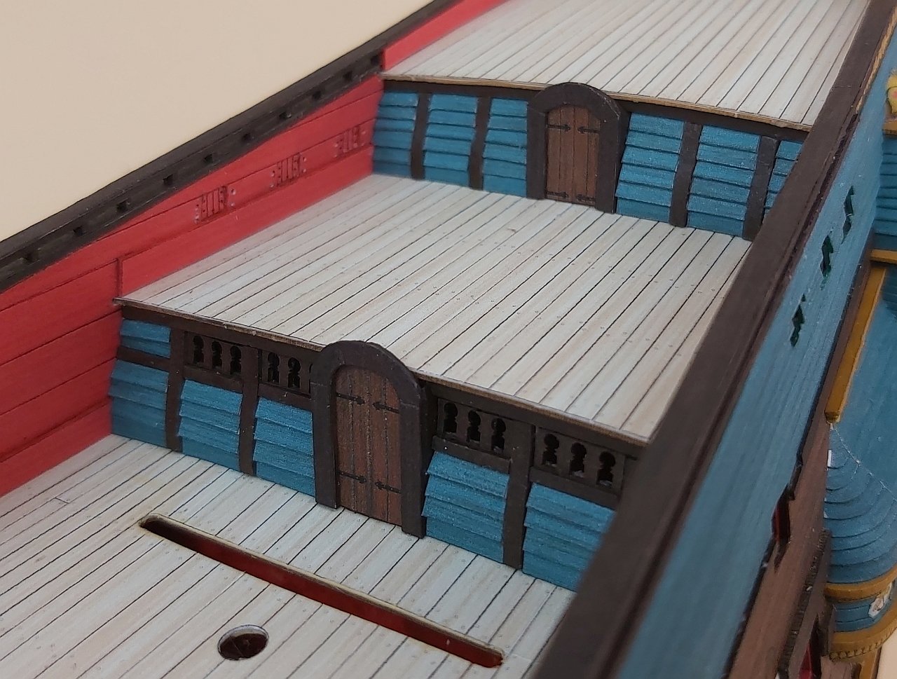
I also started making bulkheads, which will be covered with boards such as the sides. I added doors and posts, between which it will be necessary to fit this "paneling". Then sculptures will appear on the posts.

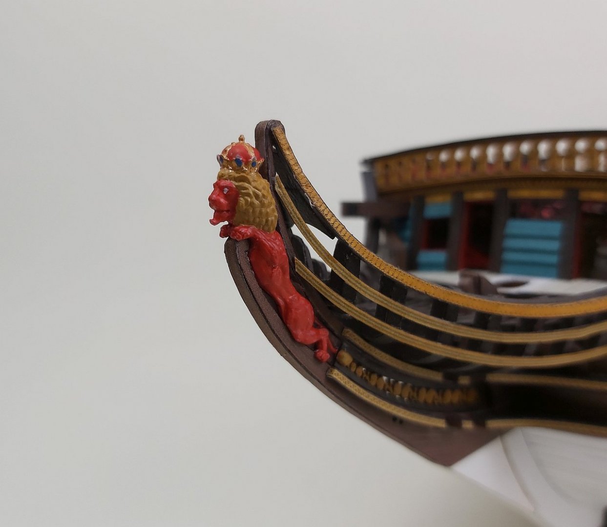
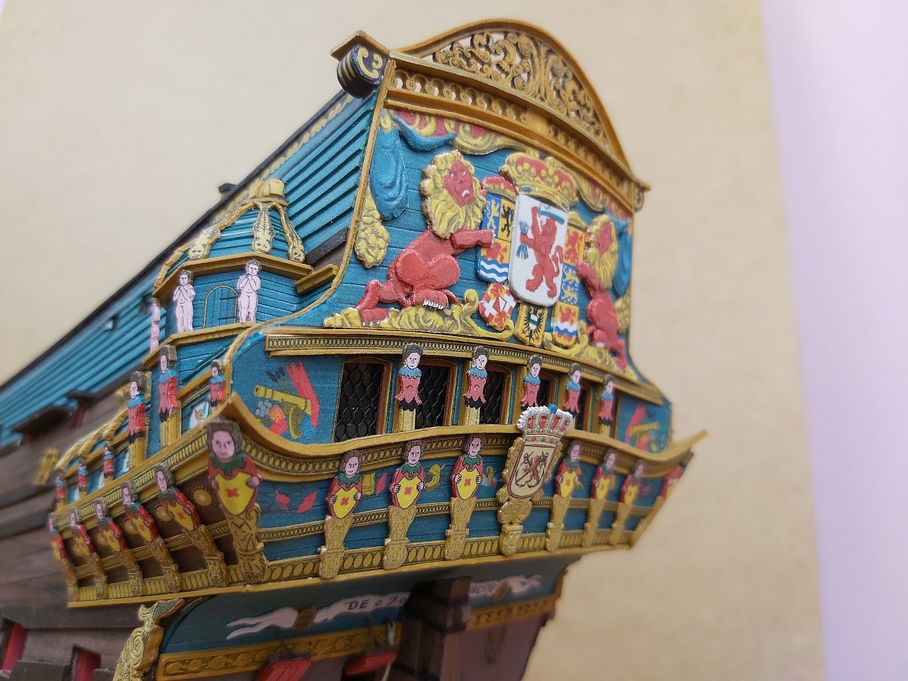
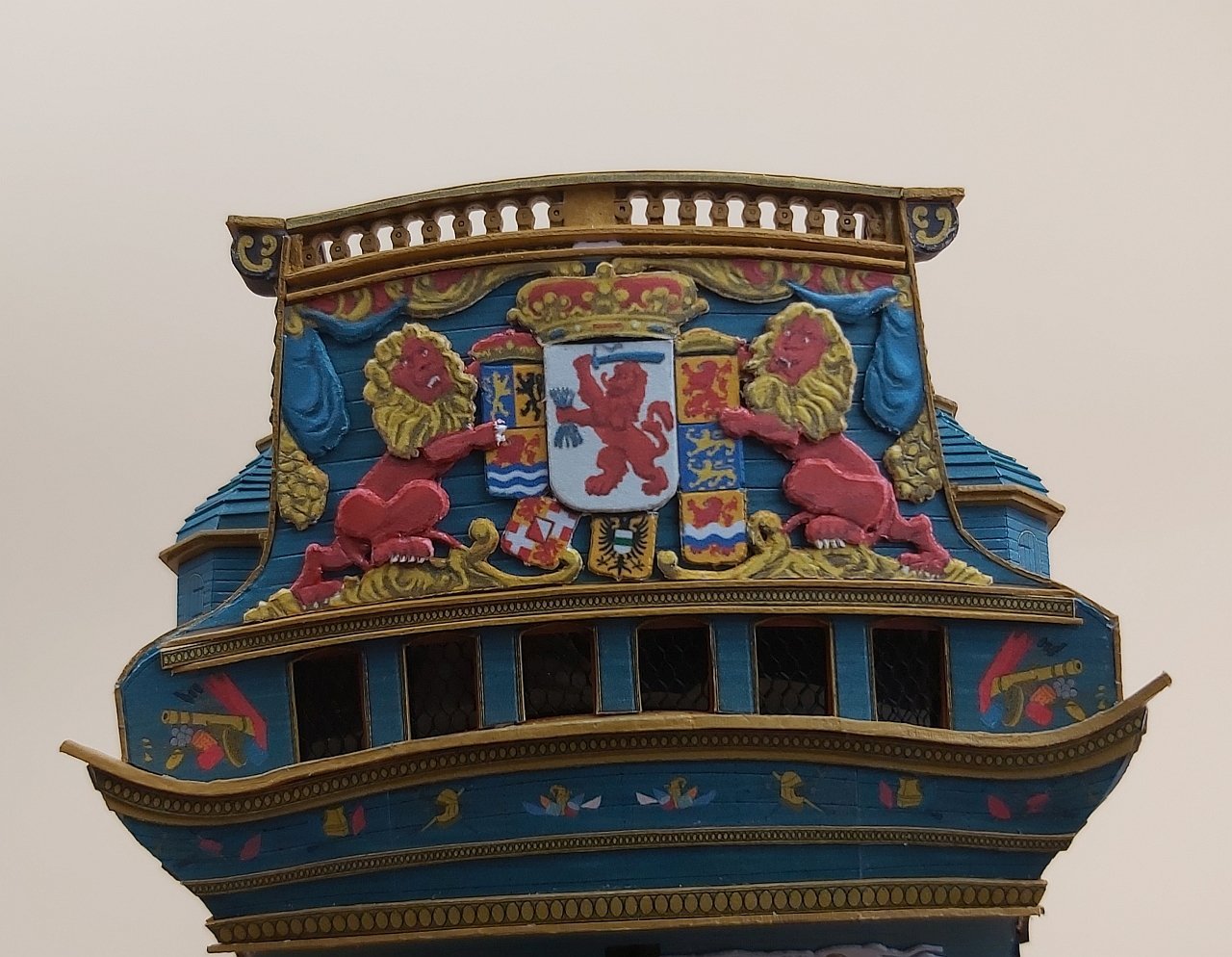
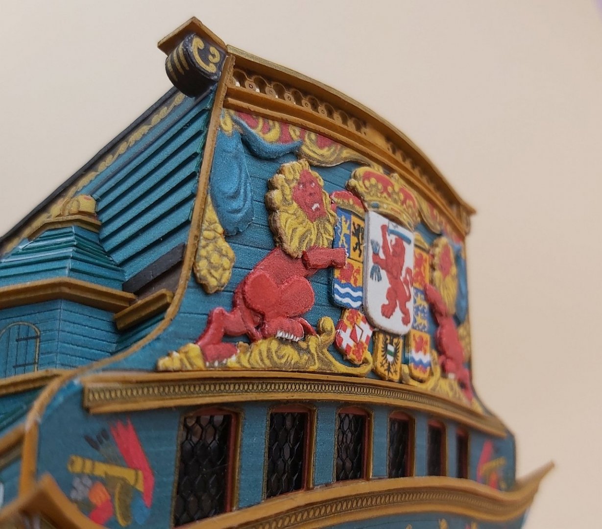
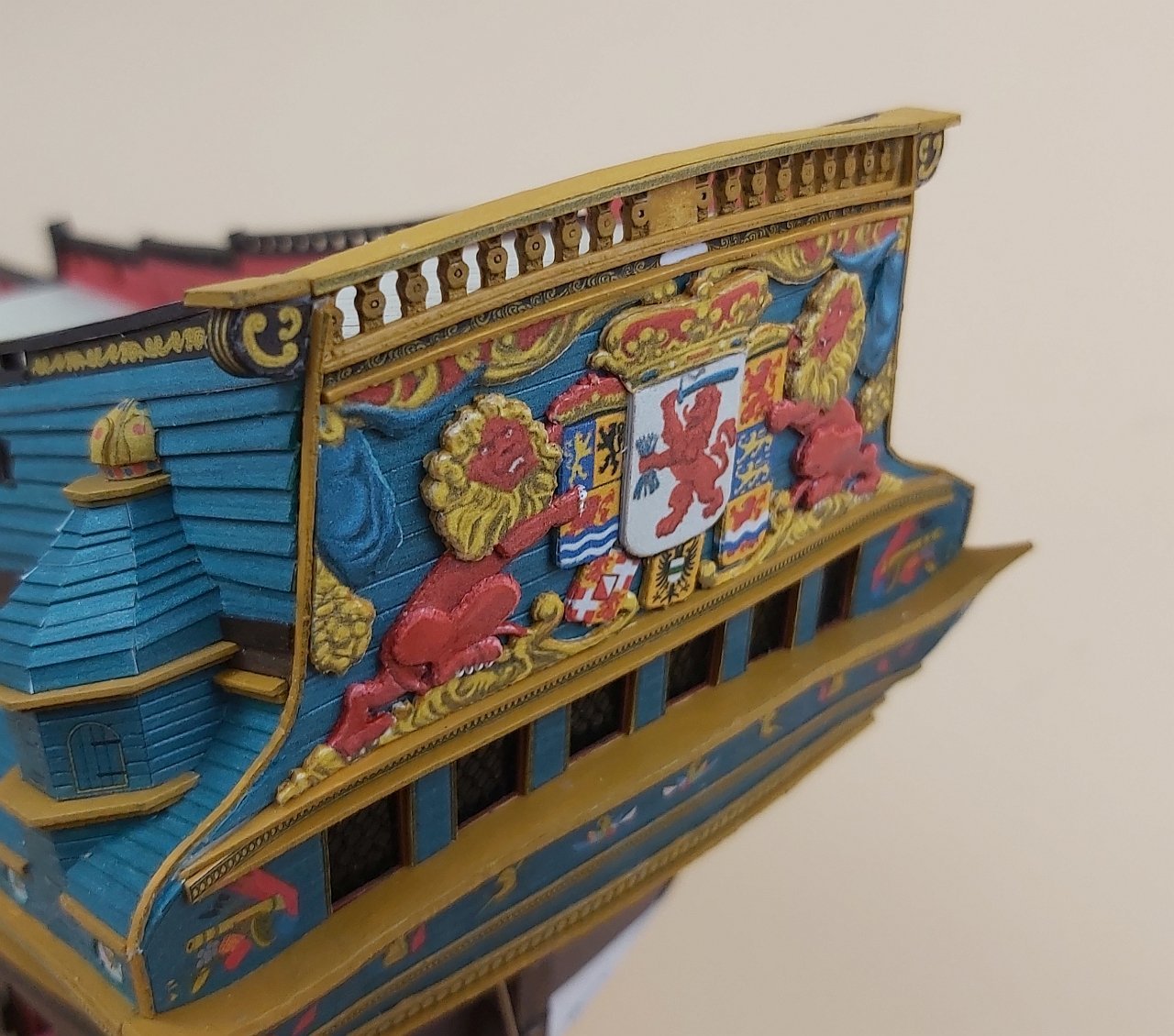
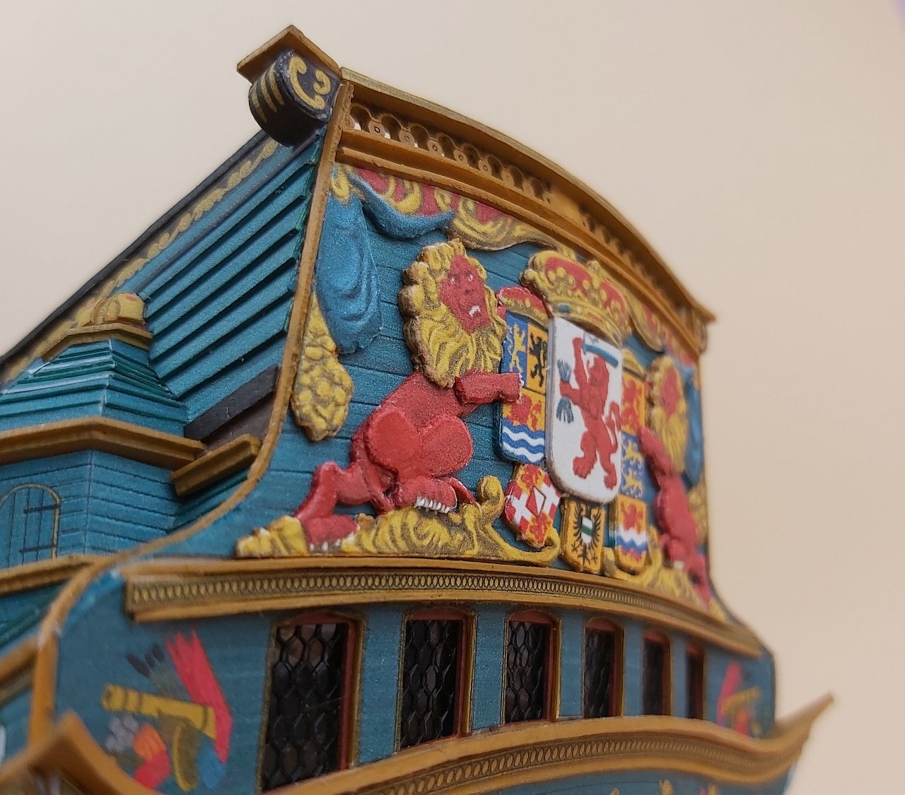
And here is the biggest challenge. All bas-reliefs can be made on thicker cardboard and can be plasticize it with thick glue, modeling clay or milliput. But I still have no idea how to design full 3D figures in the "cardboard standard": two lions at the top of the stern between which there is a "holy maiden" and something like Neptune / Poseidon above the galleries. Various attempts may take a long time, so for now I am trying to decorate taffrail and here I would like to thank my friend Tomasz Król (he is also a designer of cardboard models and a painter, many kit covers are of his works), who, using his magic powers, drew a plasticized version.
And below the port side which looks a bit better :
Greetings
Tomek


- Rudolf, VTHokiEE, Farbror Fartyg and 5 others
-
8
-
14 hours ago, Queenthunk Amalanathan.F said:
hello sir . i really loved to build this model.where may i find the plan. pls guide me.
Sao Gabriel was built without any dedicated plans. I compared a lot of sketches, similar studies of such vessels and based on photos from the Museum in Lisbon, I drew a model in Rhino3D. It seems to me that many years ago I saw on the internet plans similar to Sao Gabriel with the designation of the museum in Lisbon. Maybe contact them as it is often possible to get a copy from the museum for a small fee.
Greetings
Tomek


US Revenue Cutter 1815 by Jsk - Seahorse - 1/72 - CARD
in - Kit build logs for subjects built from 1801 - 1850
Posted
Good job!
I tie the thimbles with thread or rope around them, but before seizing, I secure the thread around the thimble with a minimal amount of CA glue, applied with the tip of the needle.
As for parrals, I think these beads are called "trucks", at least that's how I read Modefeld's drawings.
("Historic Ship Models" by W. Modfeld)
Boom and gaff probably definitely had these "beads". In the case of yards, it could be an ordinary truss pendant (i.e. just a rope).
("The Global Schooner" by K. H. Marquardt)
The suggestion to use wire insulation is simply an imitation of these beads, as they are so small that making them by hand without precise tools may be very difficult.
Best wishes
Tomek