HOLIDAY DONATION DRIVE - SUPPORT MSW - DO YOUR PART TO KEEP THIS GREAT FORUM GOING! (Only 20 donations so far - C'mon guys!)
×

0Seahorse
-
Posts
124 -
Joined
-
Last visited
Content Type
Profiles
Forums
Gallery
Events
Everything posted by 0Seahorse
-
 Hi Ab, it is something strange with "silkspan", as I was looking for it some time ago and didn't find it. It was used for RC models, but I found only paper called "Japanese paper", what seems to be the same. Very thin and very strong stuff, half-transparent so it should be painted before with acrilic paints. There are some movies on YT how to make sails of silkspan, but look there. Best Tomek
 -
I think, that she will be published in autumn, don't know the publisher yet. Best Tomek
- 14 replies
-
- 2
-

-
- sao gabriel
- caravel
- (and 3 more)
-
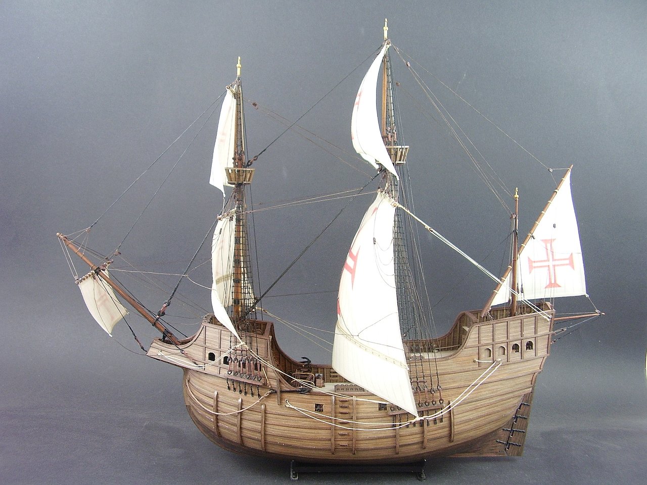
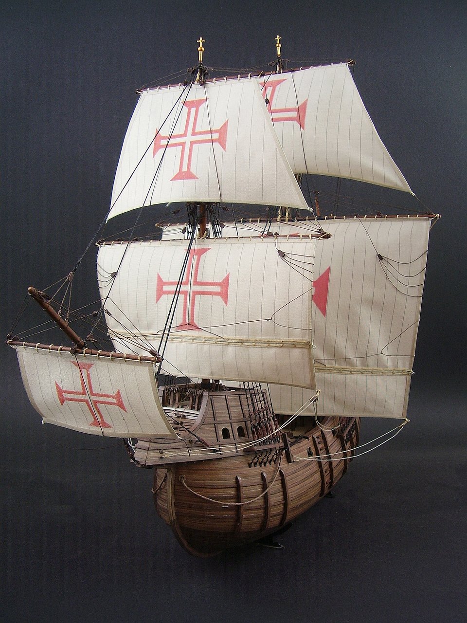
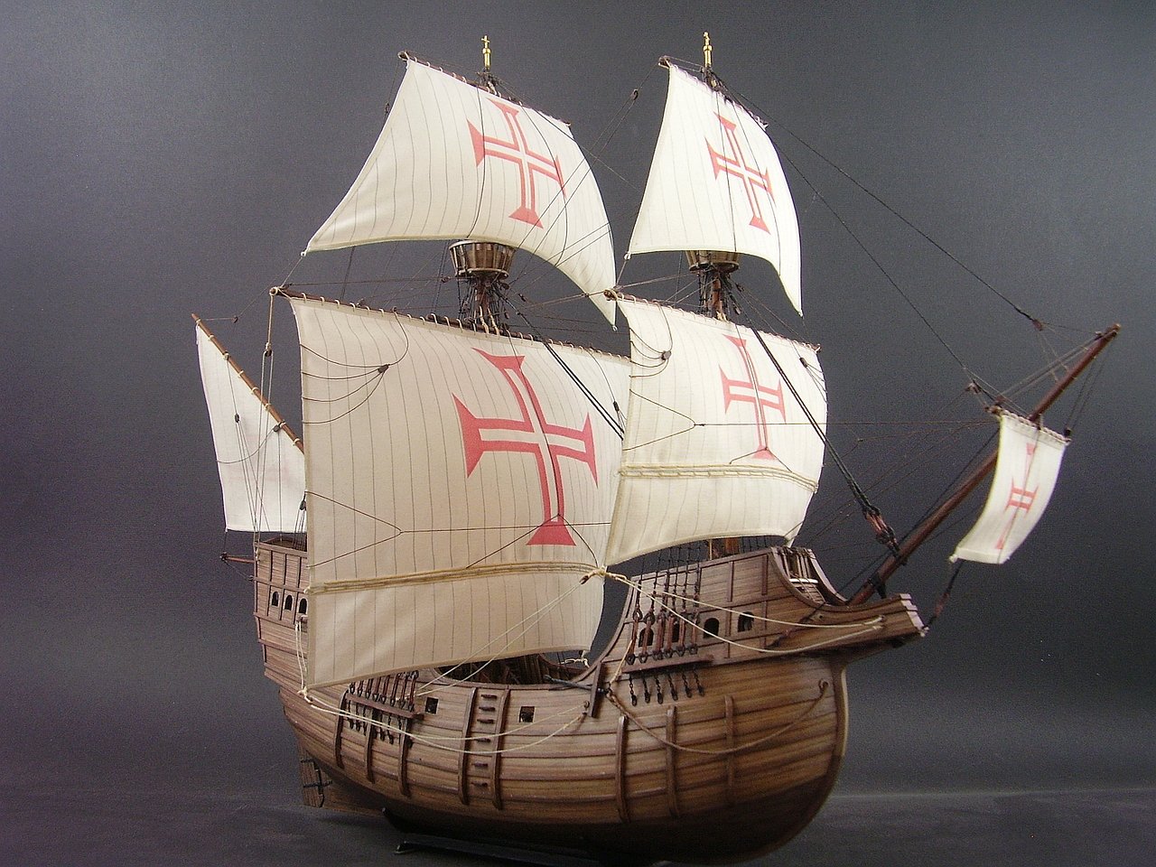
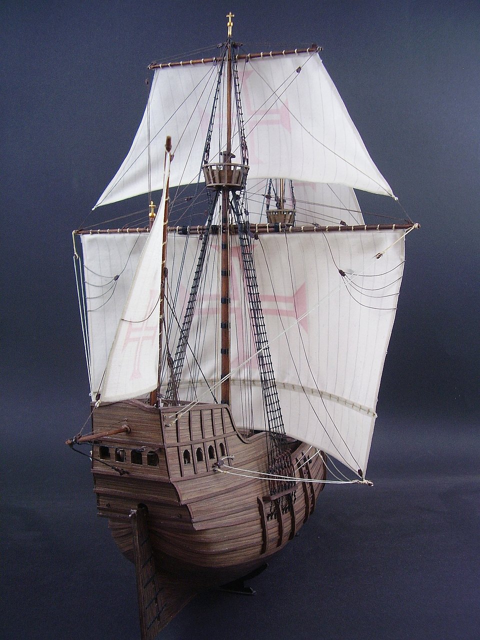
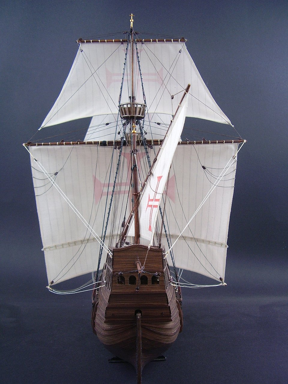
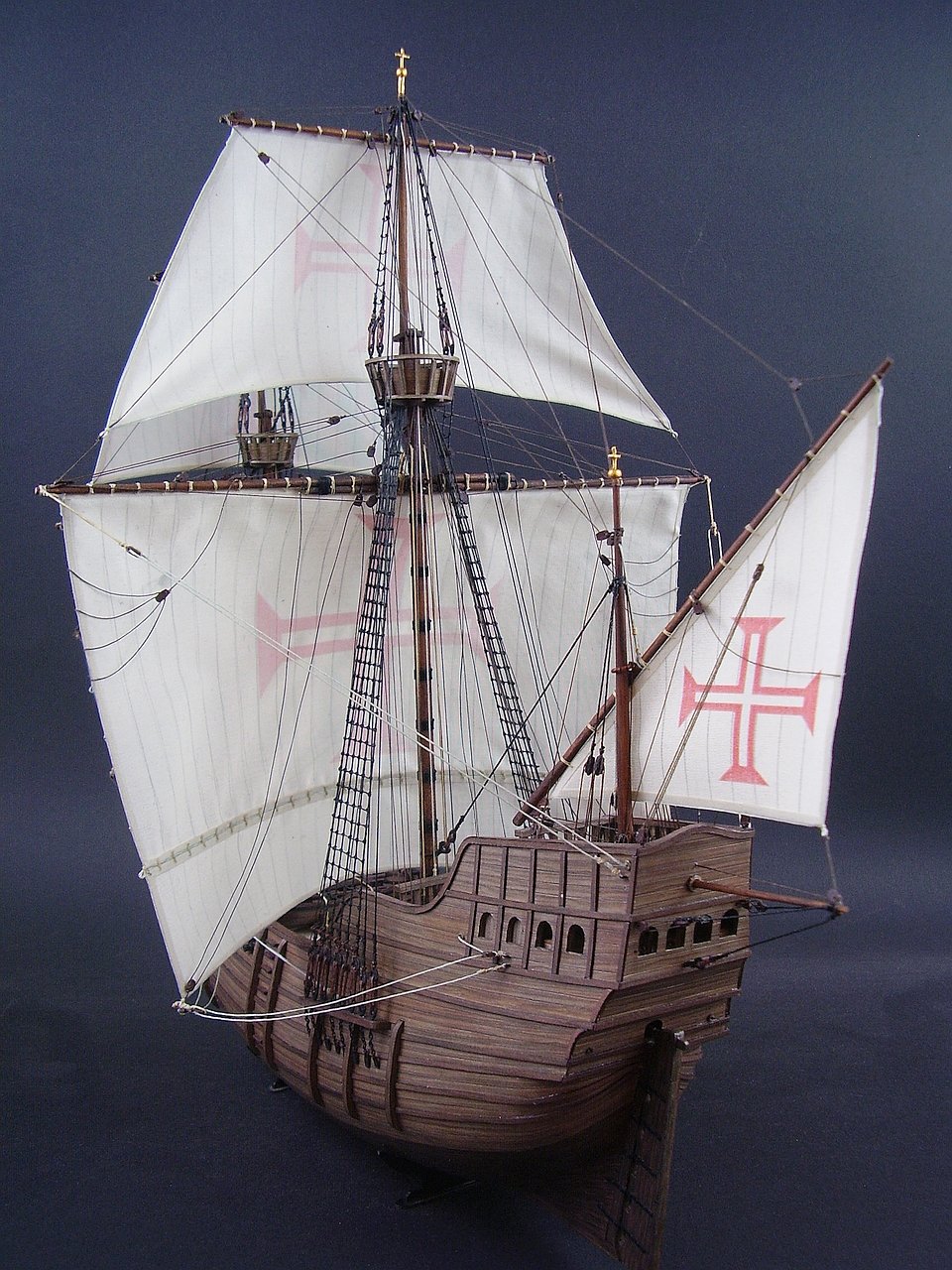
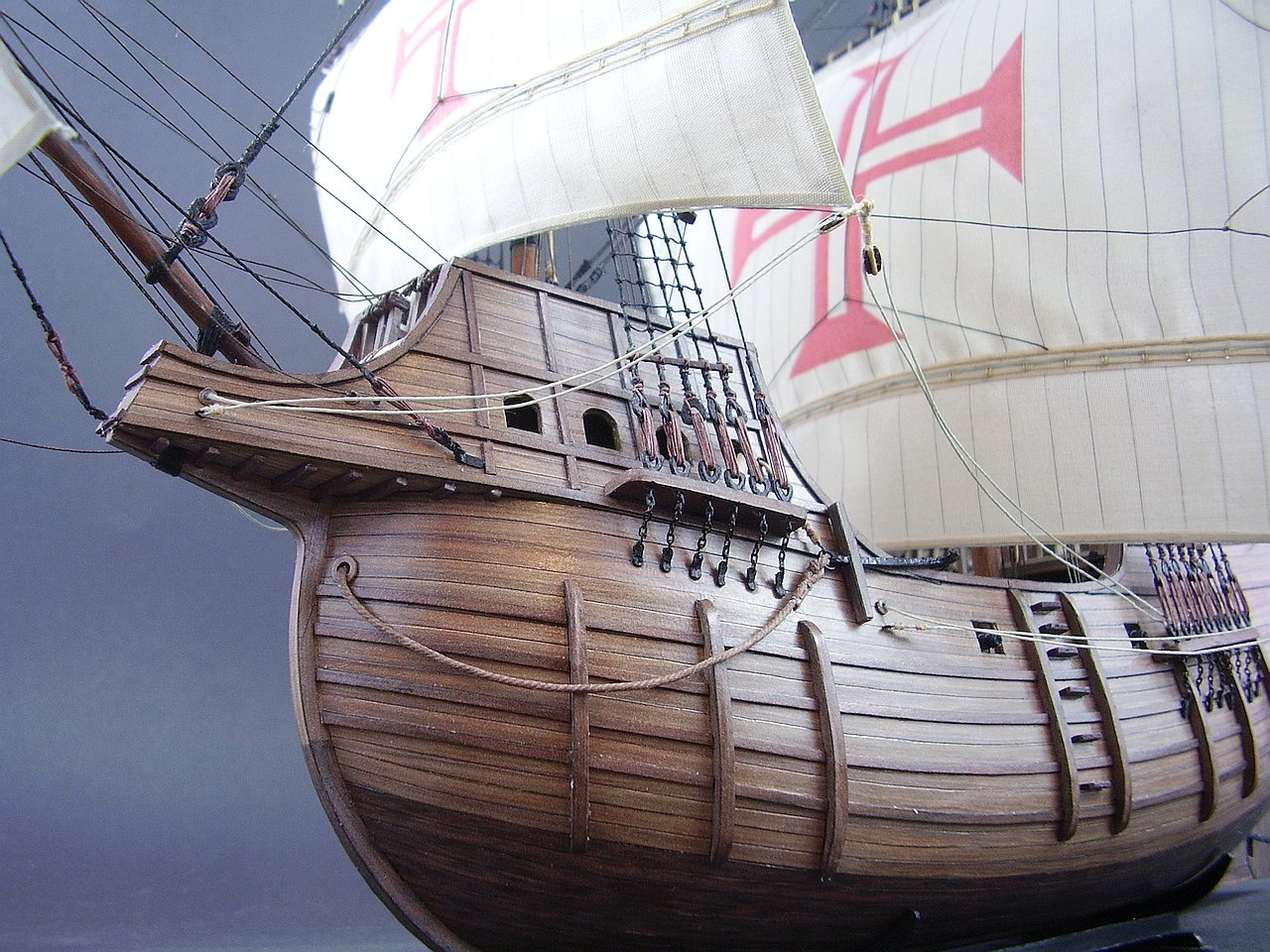
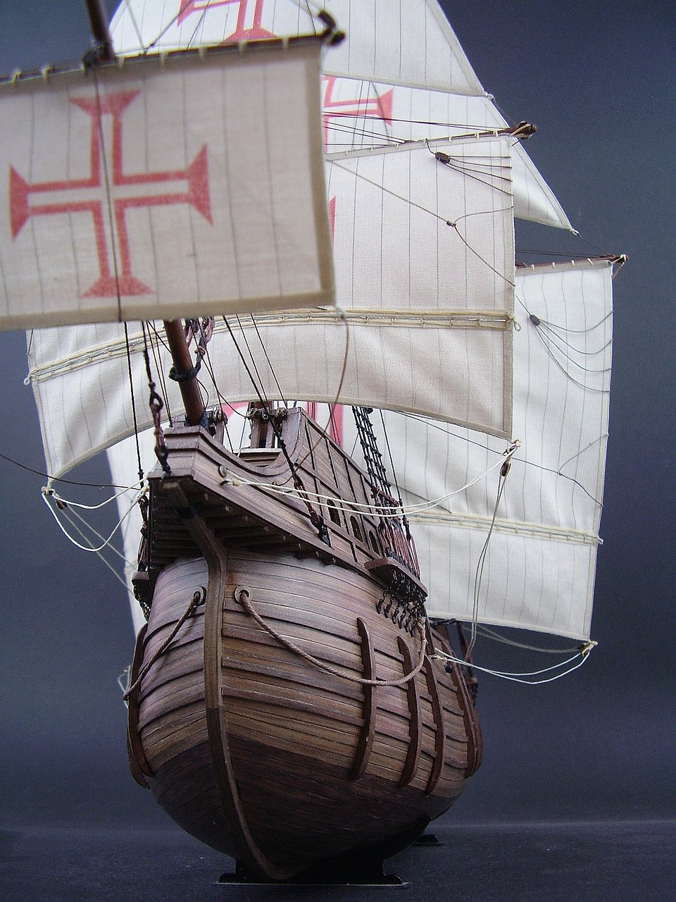
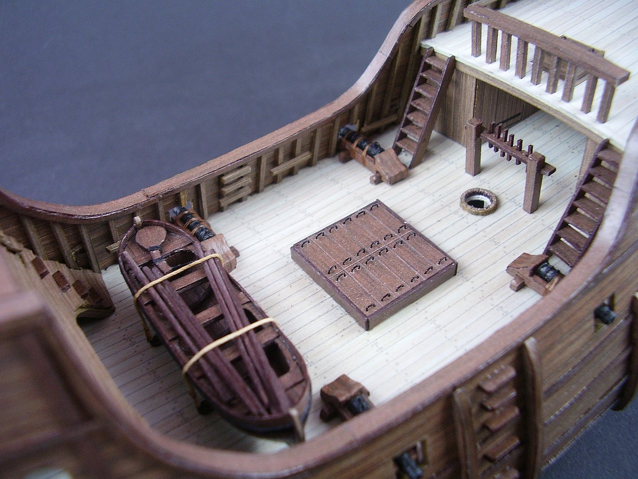
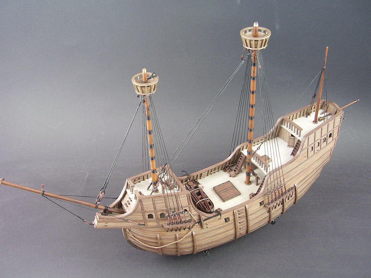
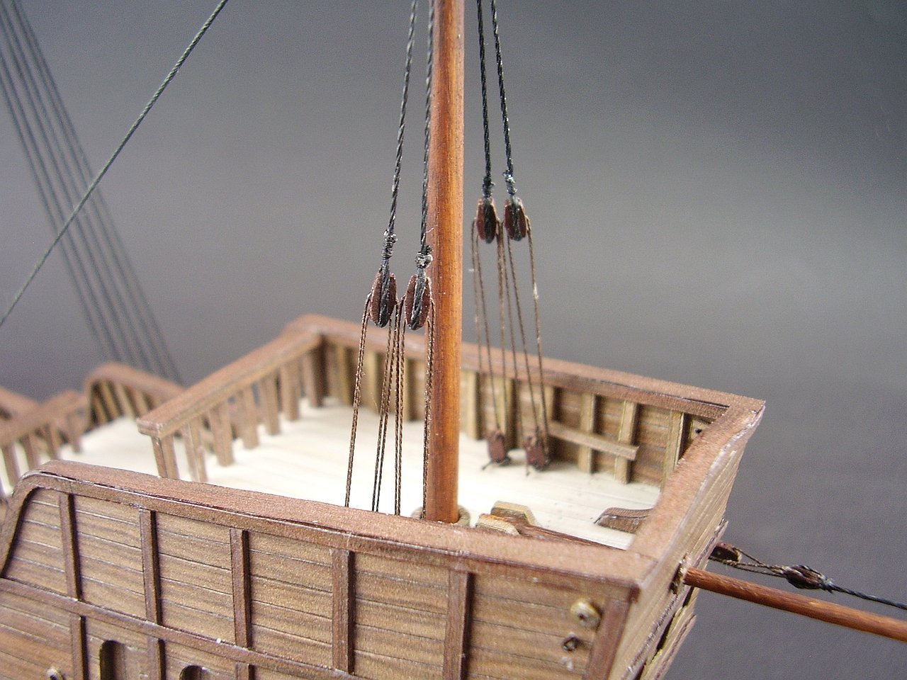
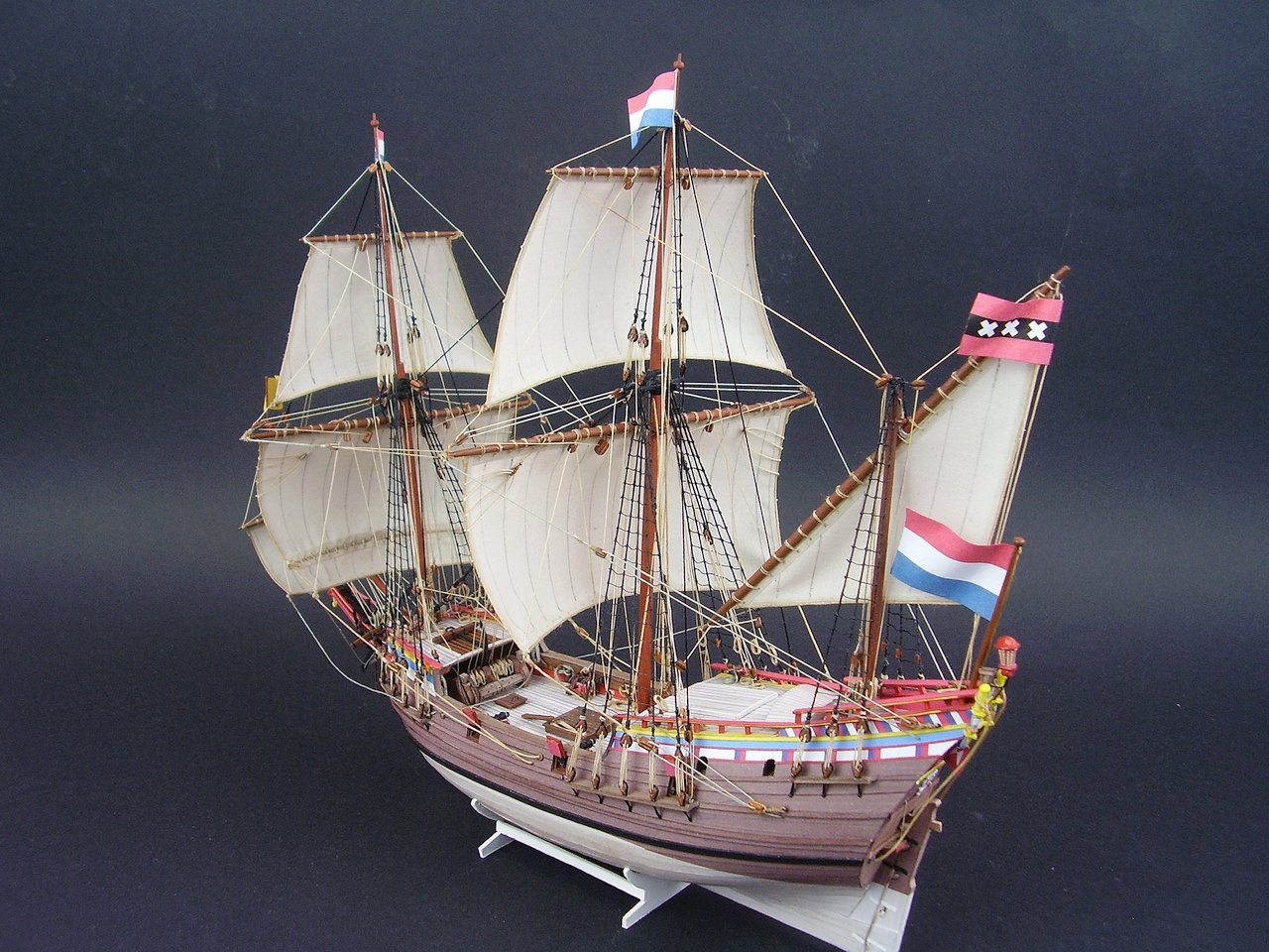
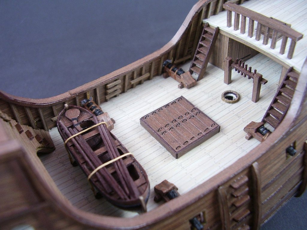
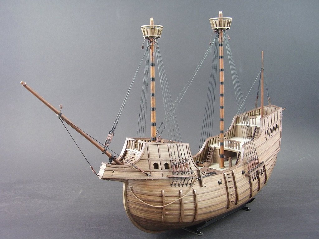
Hi, It took me a lot of time to finish some details, but finally I set up masts and have something new to show. Best Tomek


- 14 replies
-
- 12
-
-

-
- sao gabriel
- caravel
- (and 3 more)
-
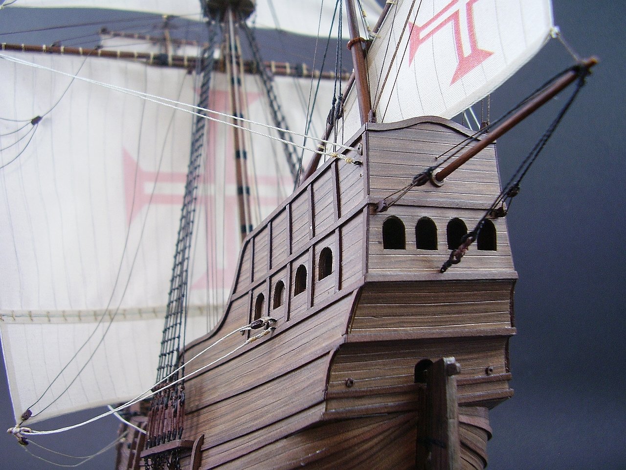
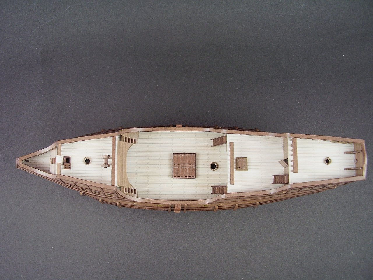
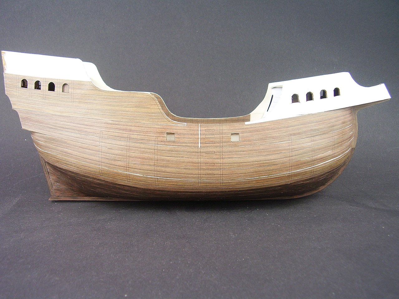
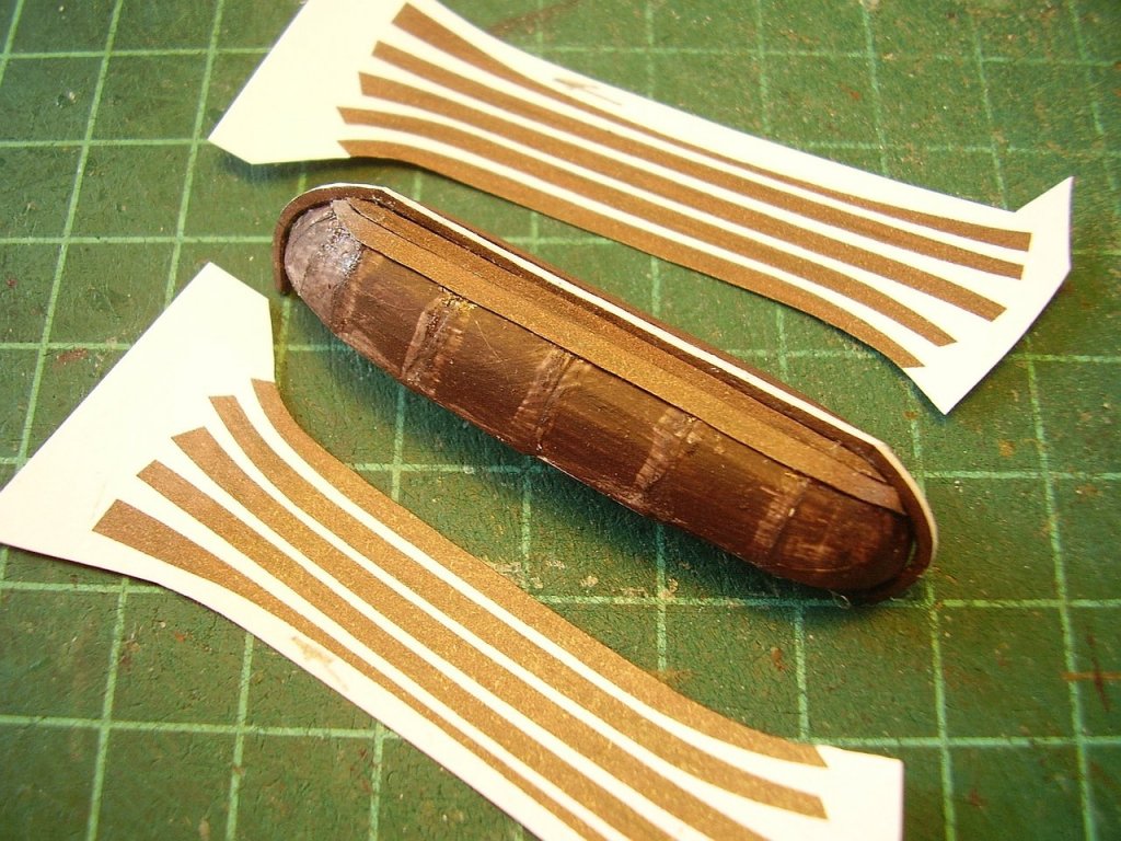
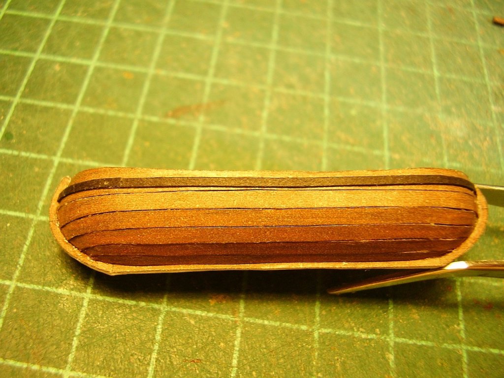
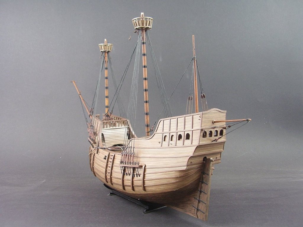
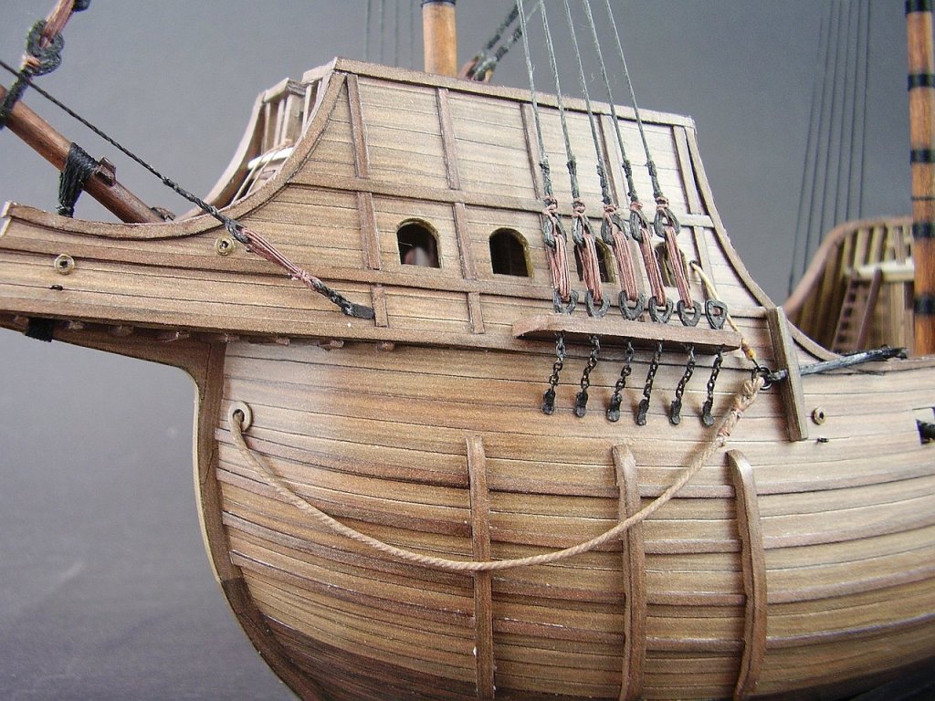
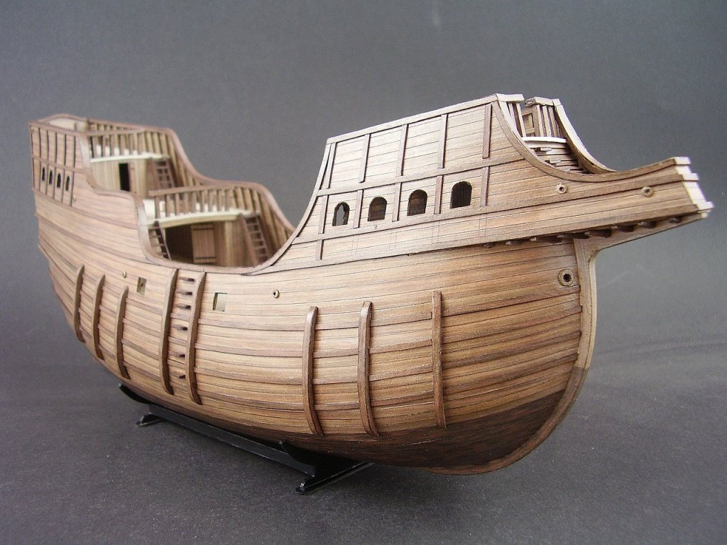
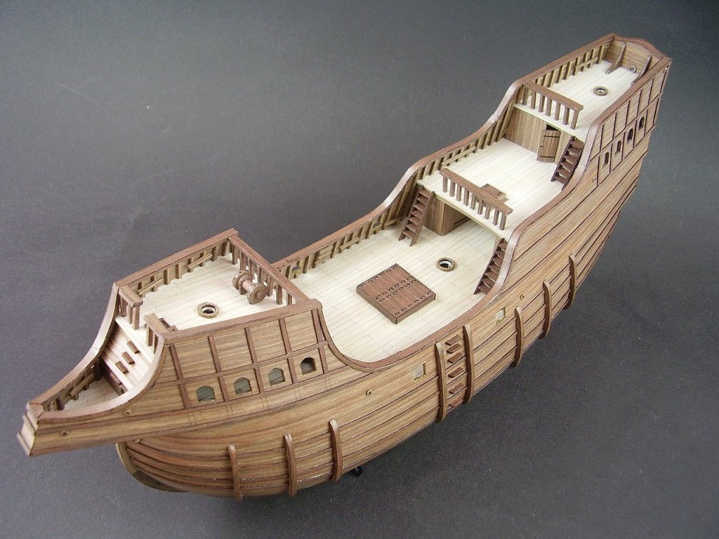
Hi, I built 99% of the hull and its details. All parts with a thickness of +1 mm were cut from cardboard and glued on three sides with stripes of appropriate width. For sure the construction would have been faster if I just painted these parts. Best Tomek

- 14 replies
-
- 13
-
-
-
- sao gabriel
- caravel
- (and 3 more)
-
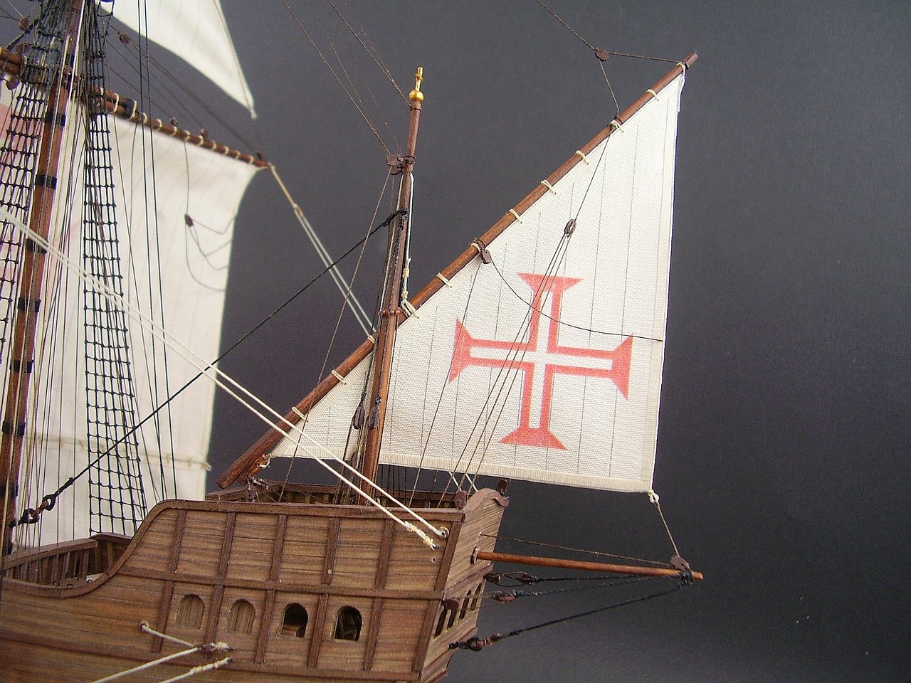
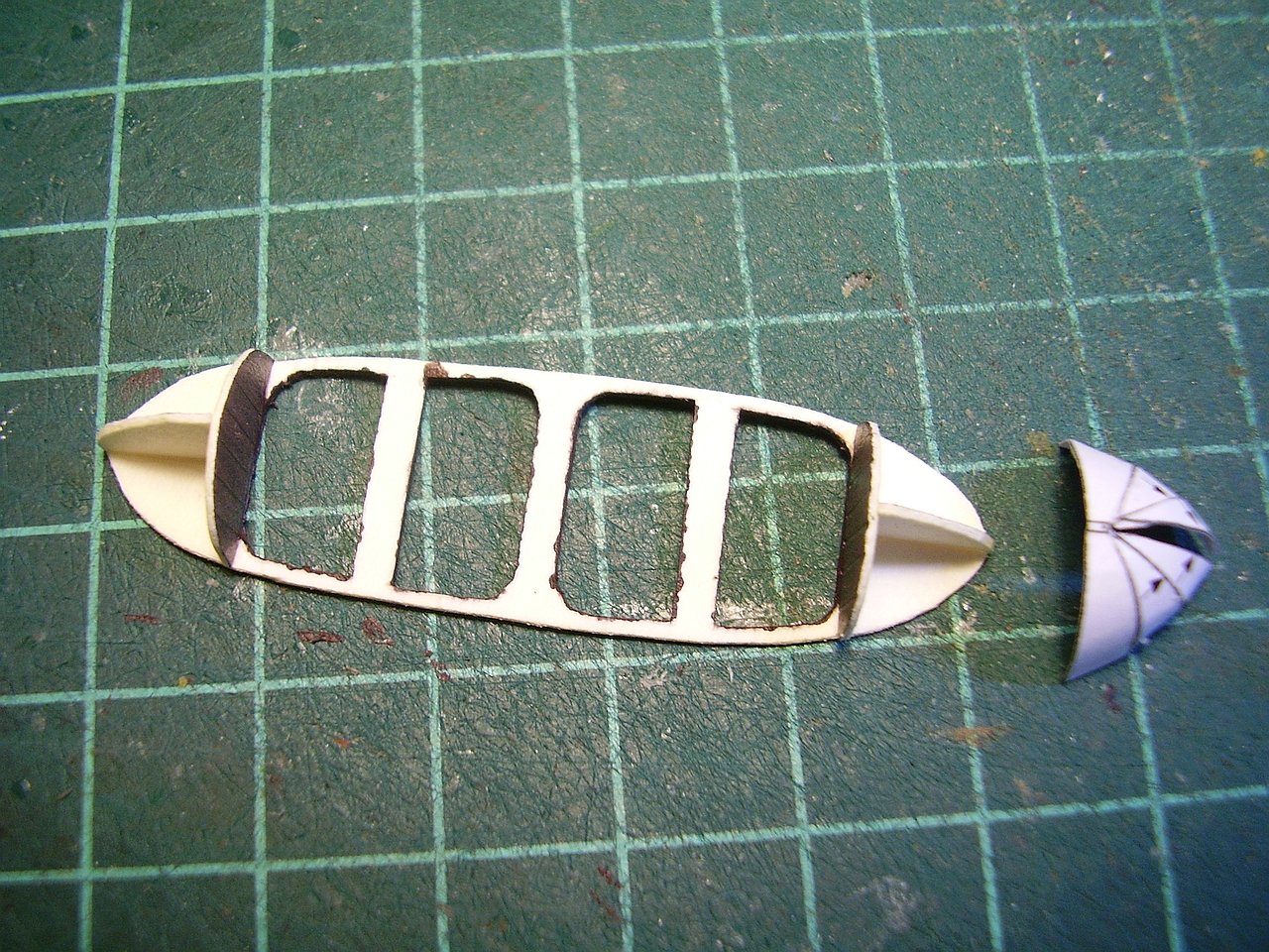
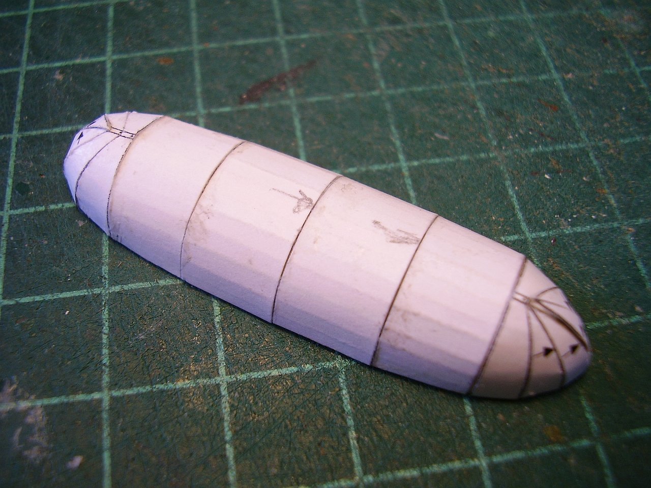
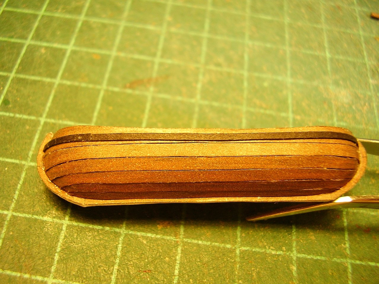
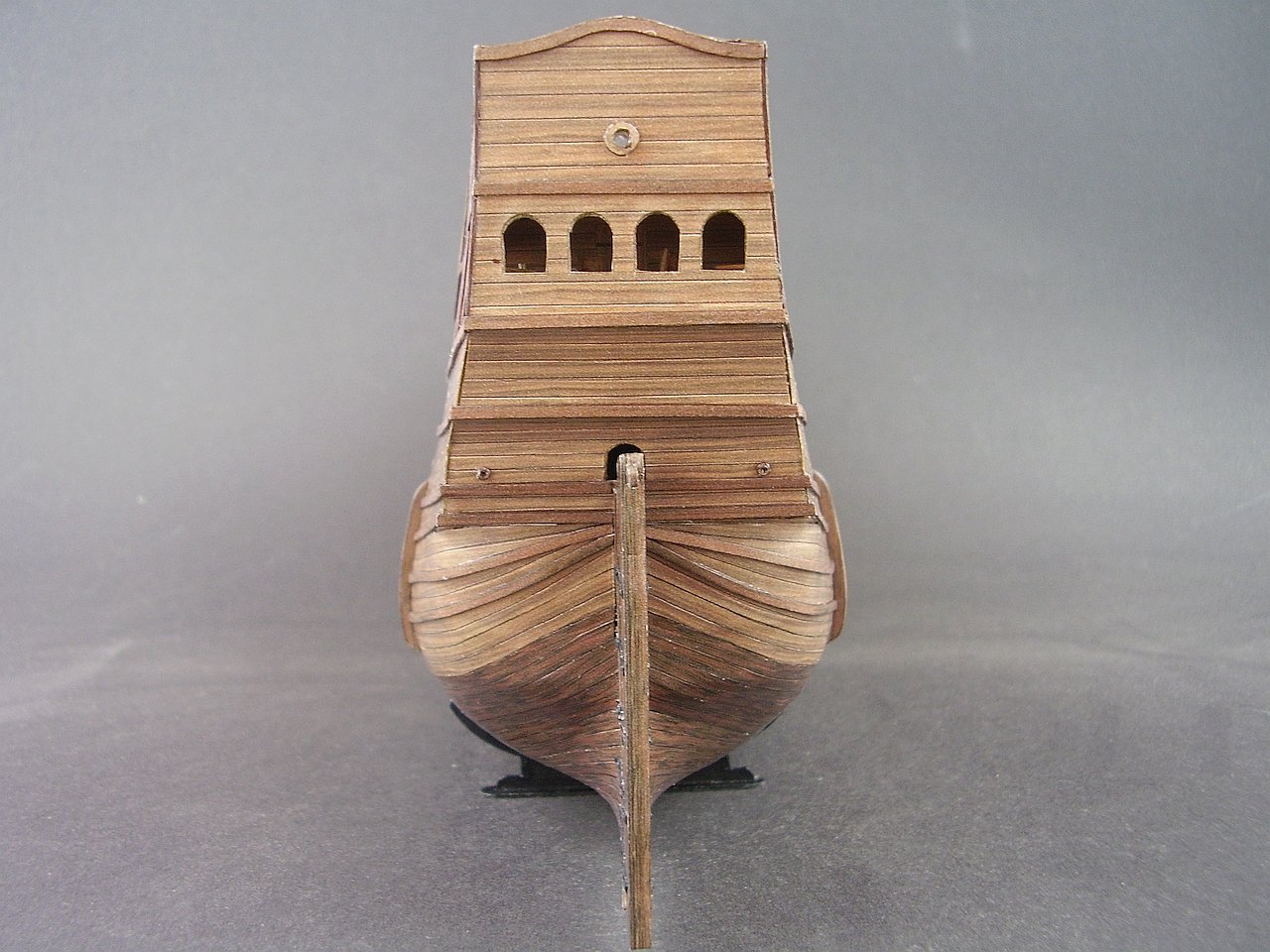
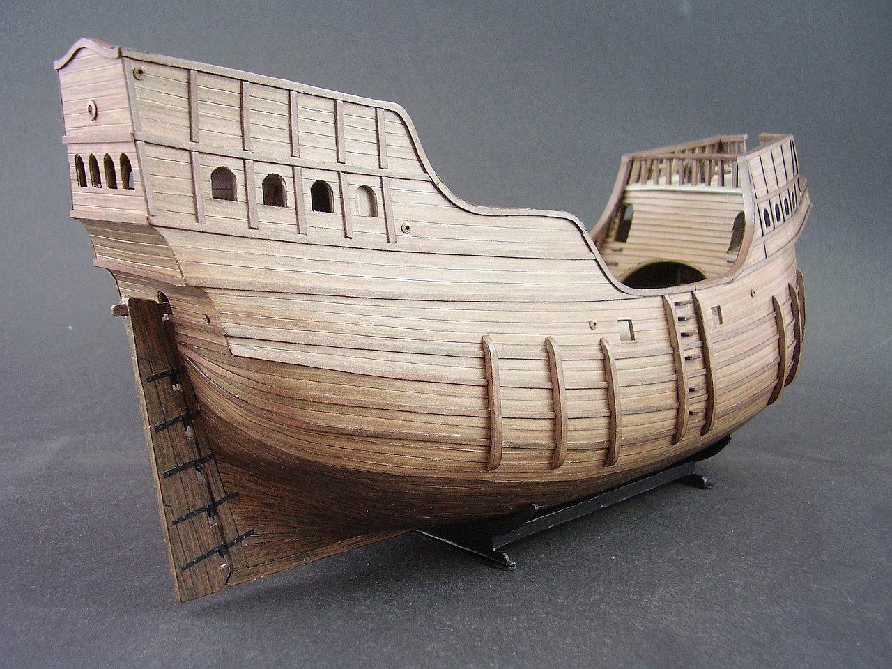
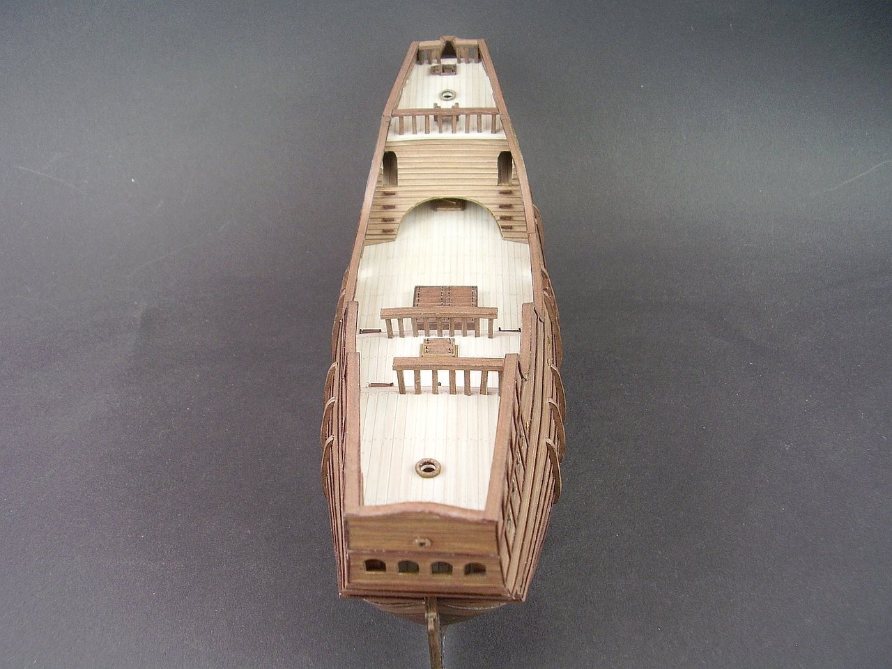
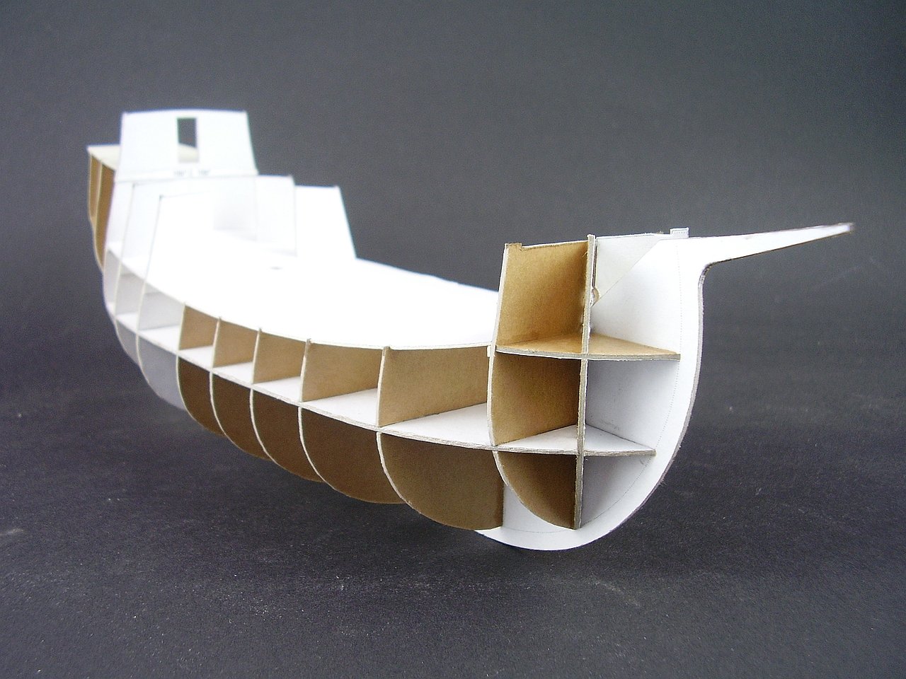
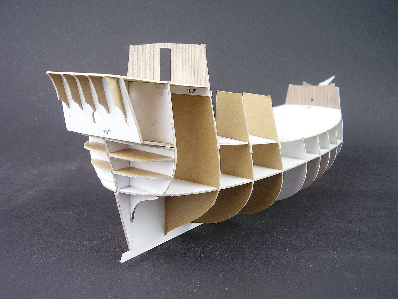
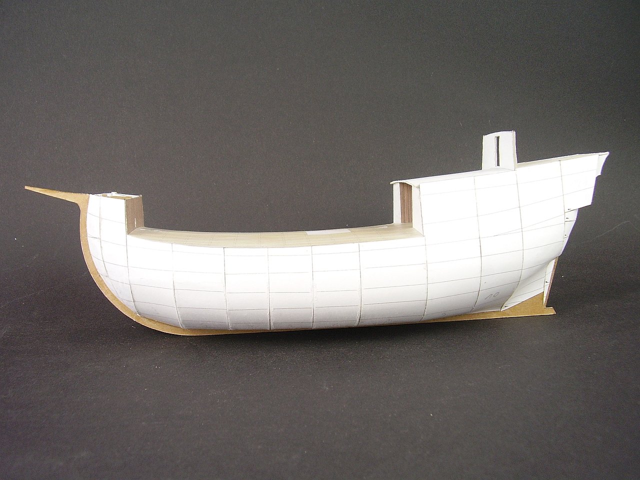
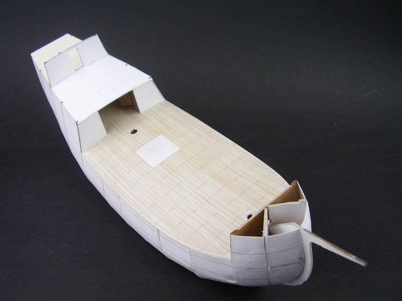
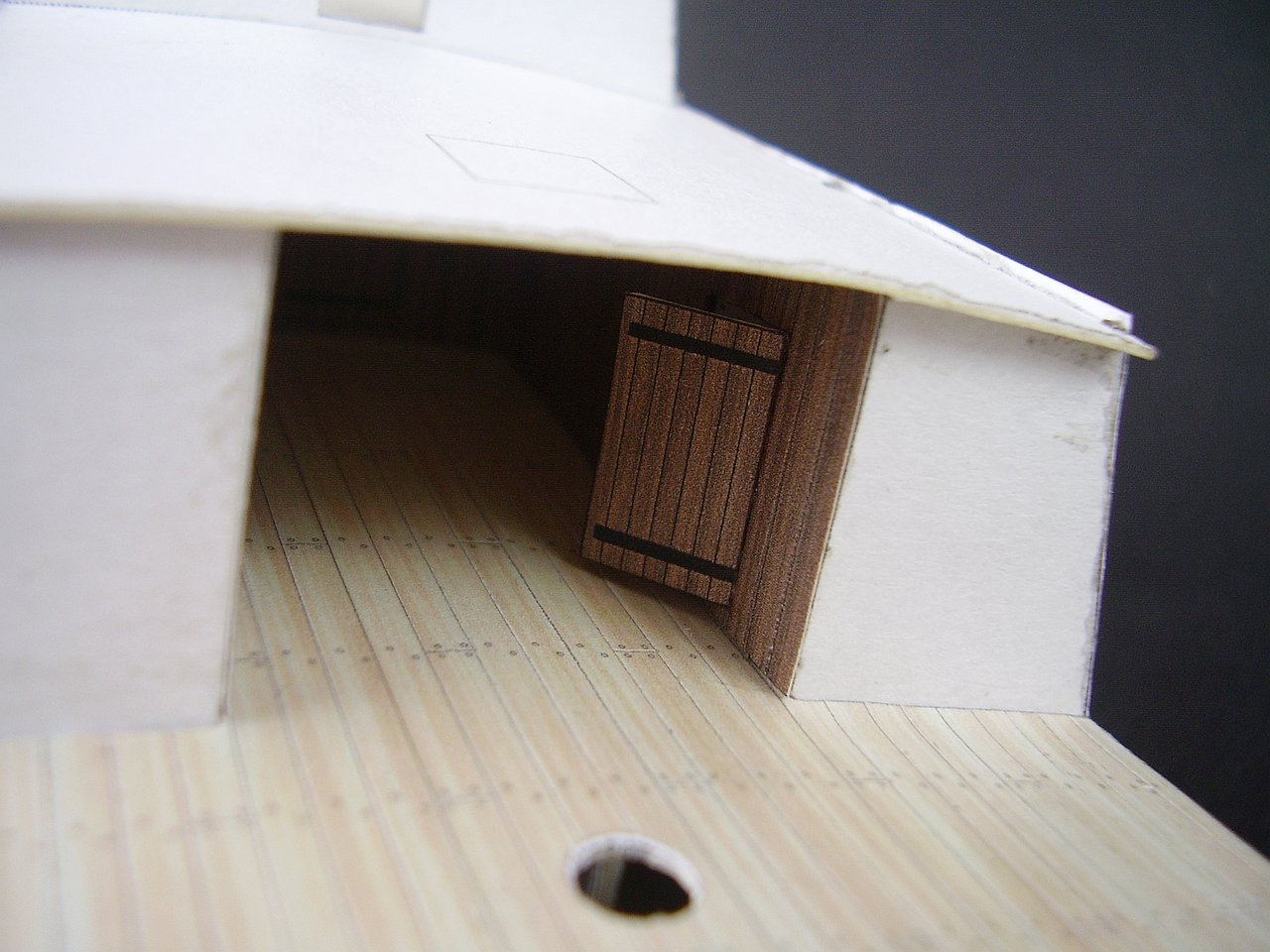
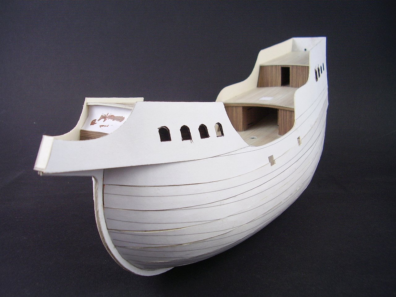
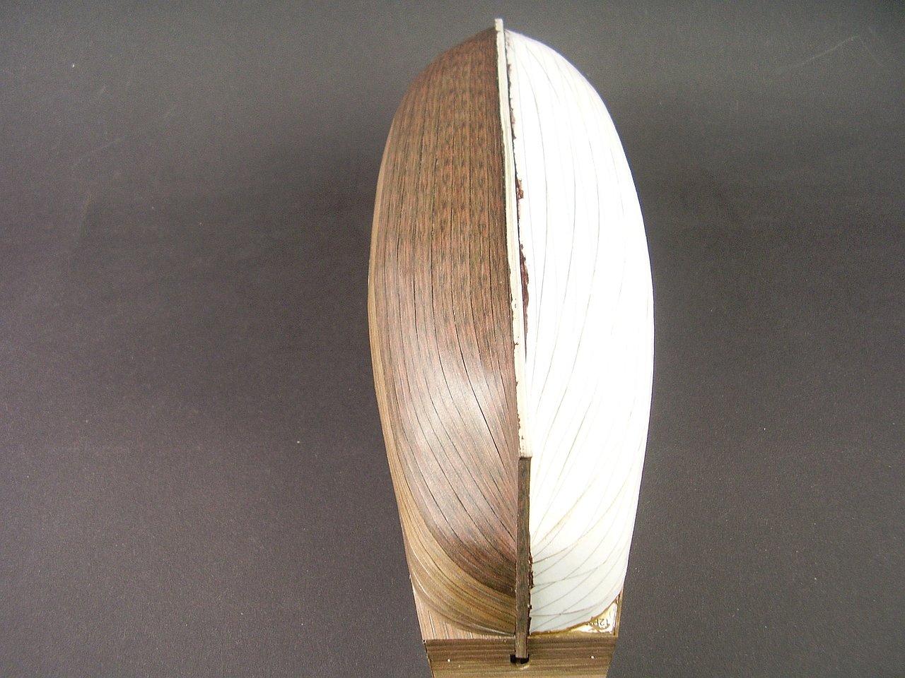
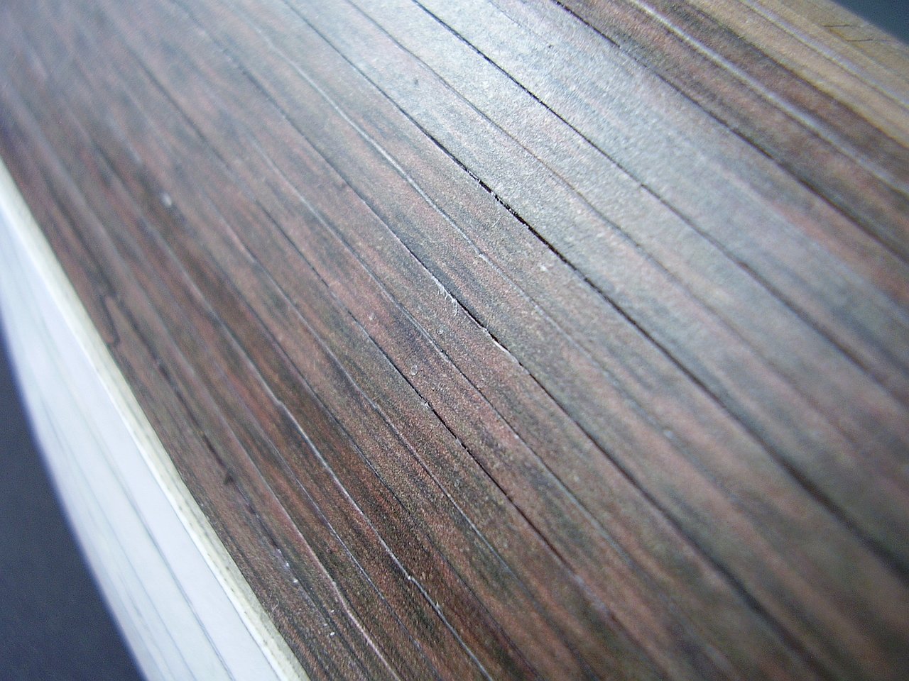
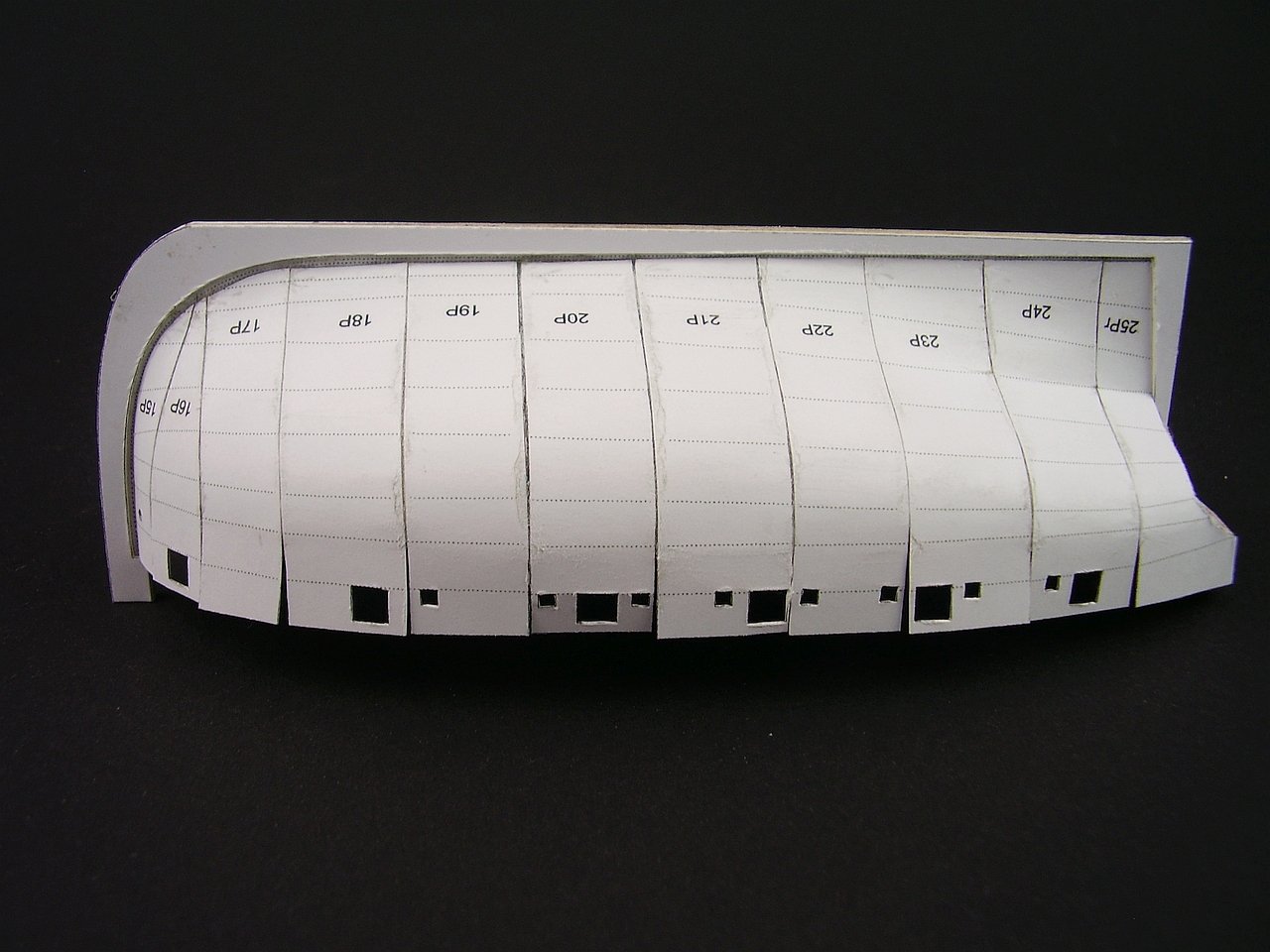
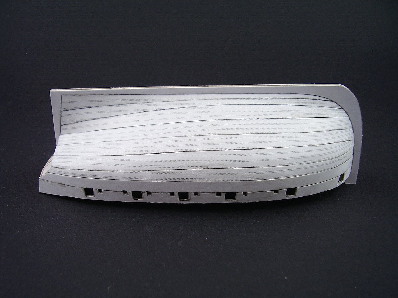
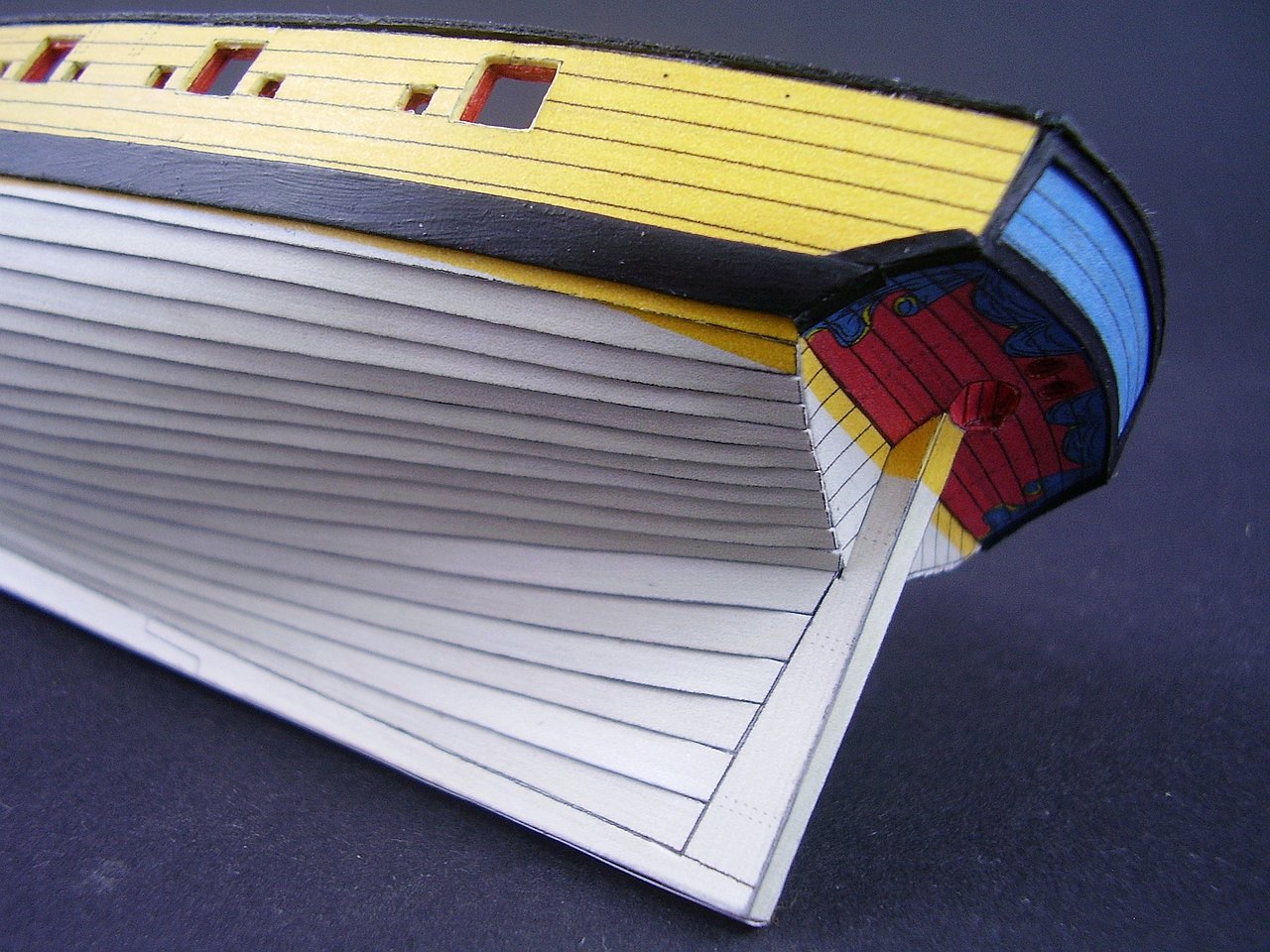
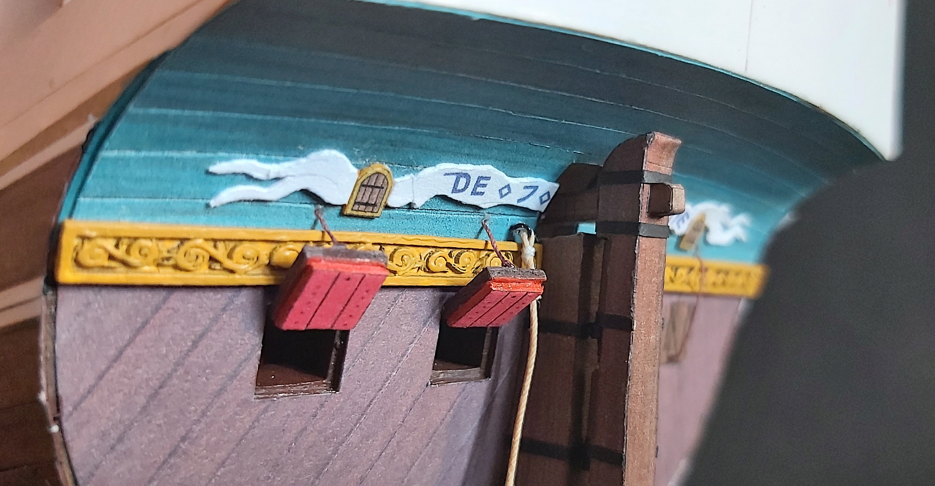
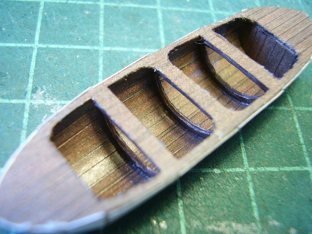
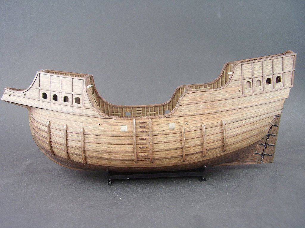
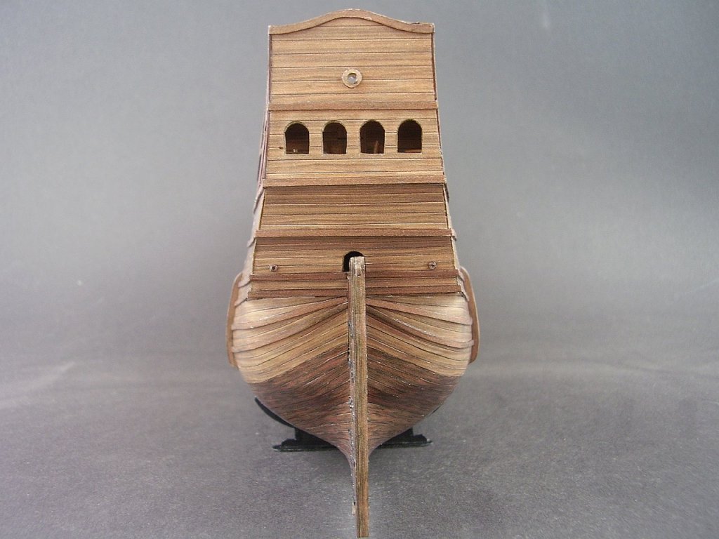
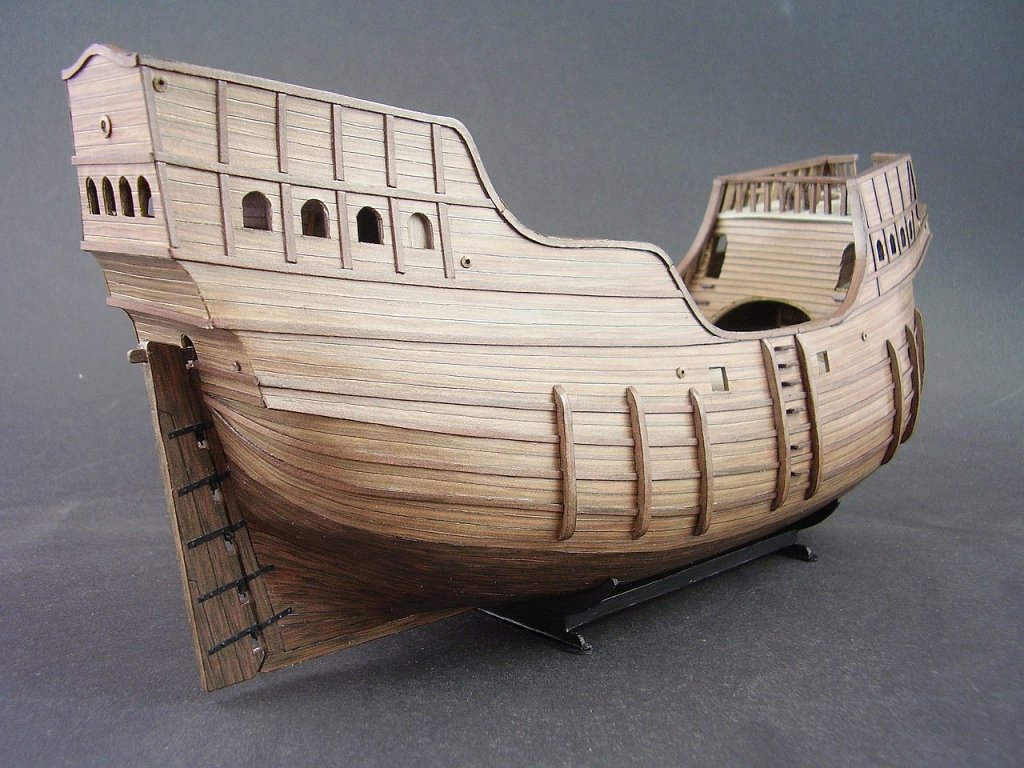
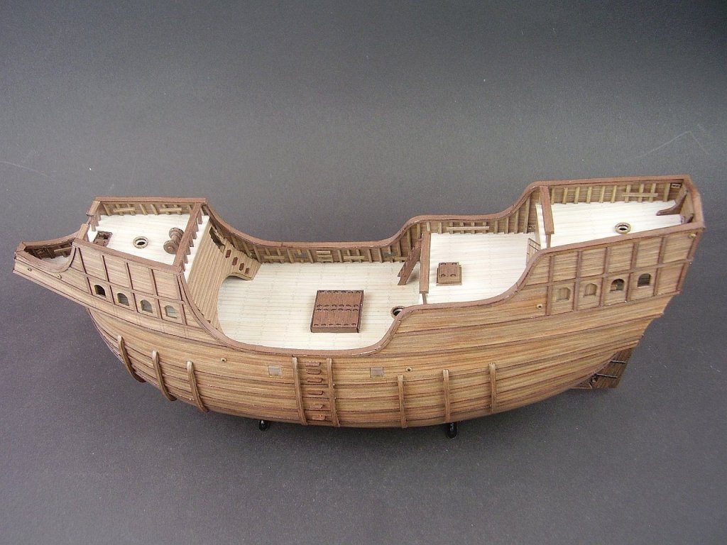
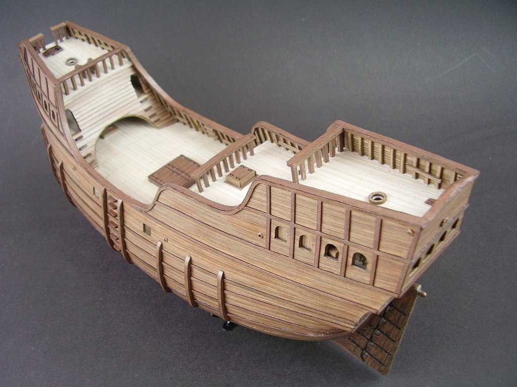
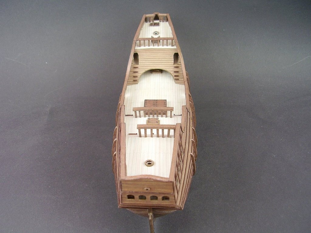
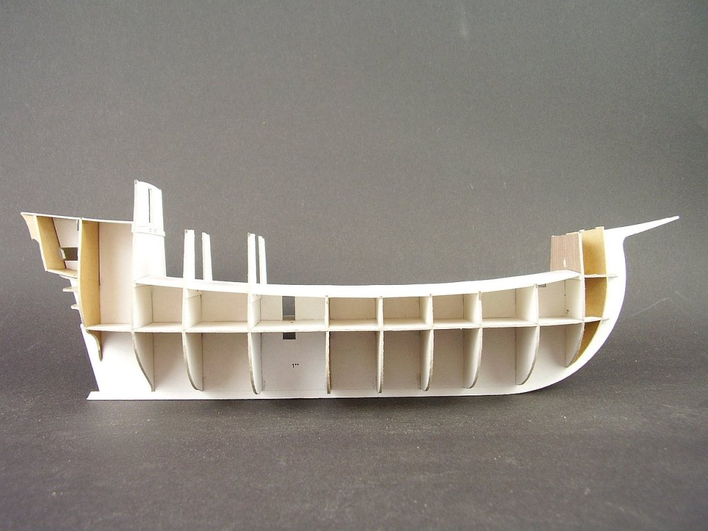
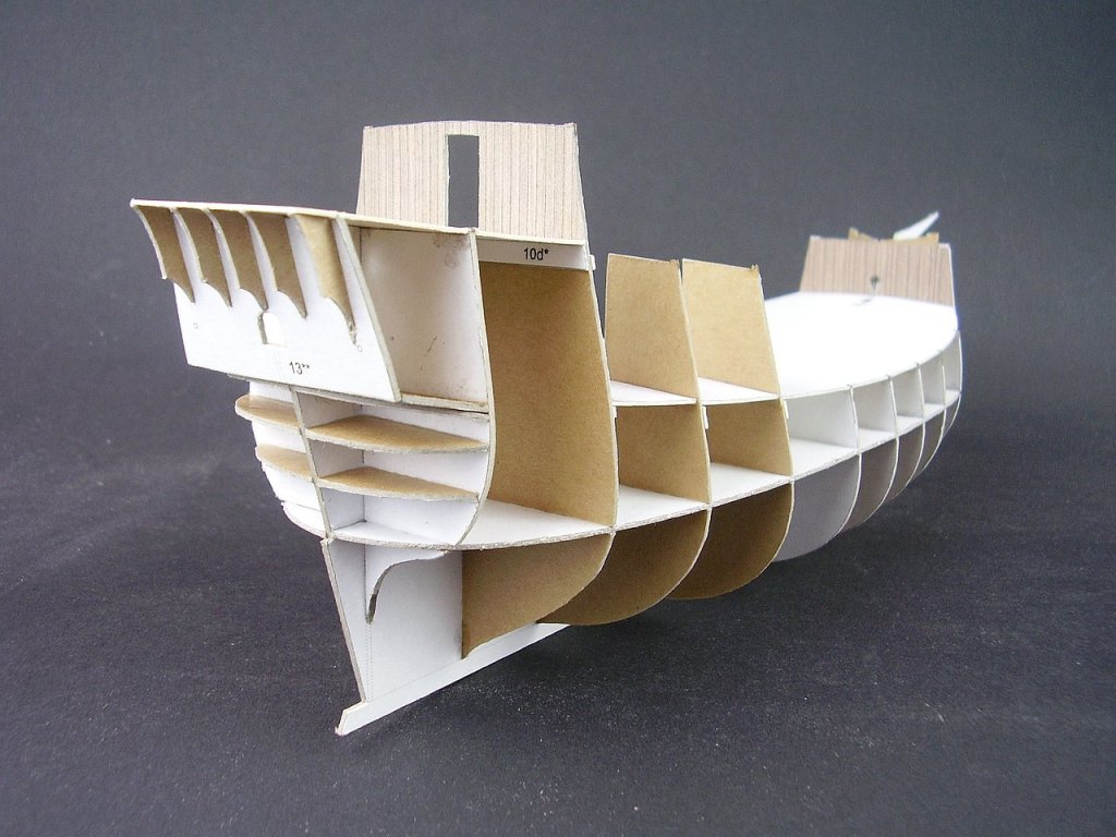
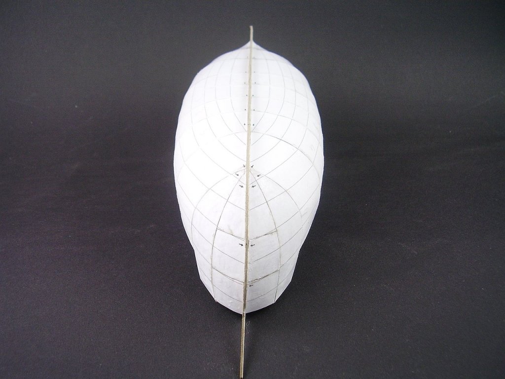
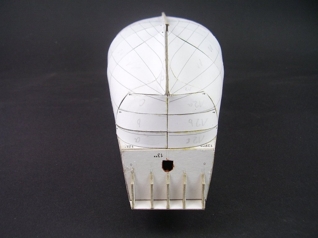
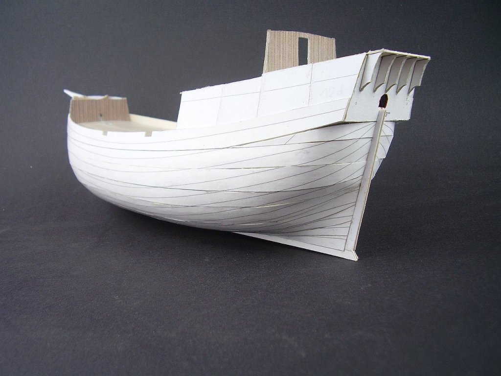
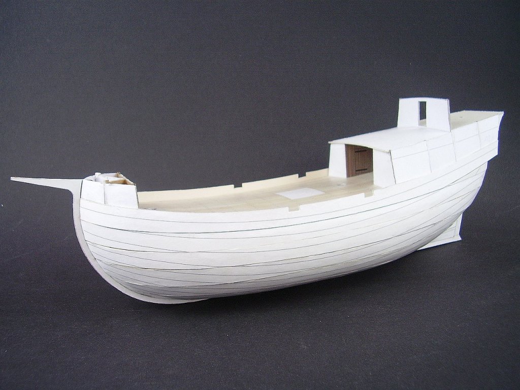
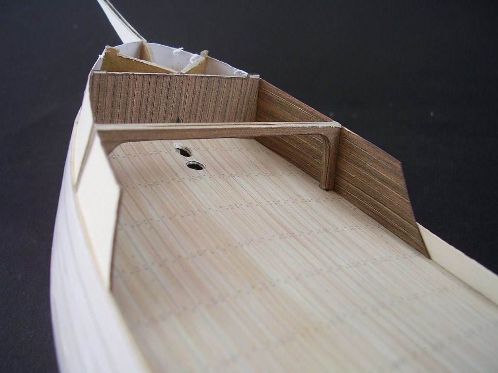
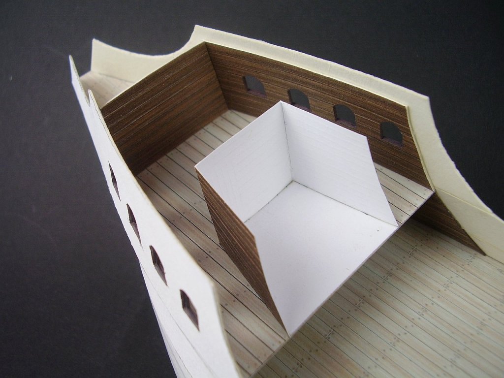
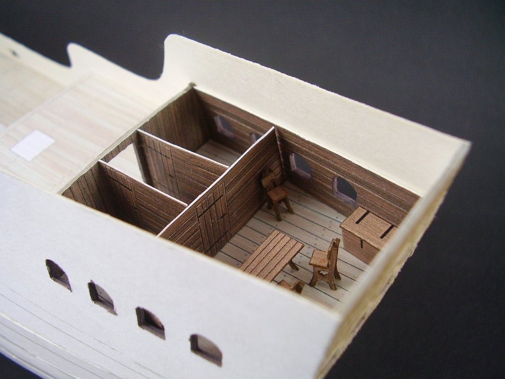
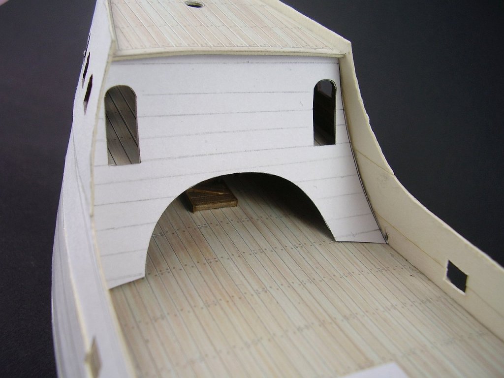
Hello Some time ago I started building Sao Gabriel based on the model in the museum in Lisbon. I do not have exact plans, but based on photos, dimensions and proportions of this type of vessels I managed to design a ship quite similar to the original. The progress in the construction is enough to show the first photos. The hull frames were made of 1 mm thick cardboard. I have planned three layers of planking: the first vertical layer, which stabilizes the frames, the second longitudinal one on the cardboard 0.5 mm and the third one in color as the final planks. After gluing the first layer, I added some of the decks and evened the entire hull with sandpaper to remove adhesive residues and greater inaccuracies. On these parts you can see lines according to which I will glue the next layer. Before sticking the next decks, I had to make a few details, which would later be very difficult to access. Then I glued the second layer, so far only to the level of the main deck and then I built a part of the forecastle. The construction of forecastle... Then, step by step, I added the next strips of the second layer and the next level in the forecastle. Because the model has a lot of windows in the stern part, I created some rooms there. Unfortunately, there are not many sources describing rooms in sailing ships from this period, so this is only my imagination. Now I could "lock" the whole with the upper decks. Before gluing the last layer, the whole hull was covered with wood glue, which made it stiffer. I smoothed the whole with sandpaper and started gluing the last layer. Each strip is two boards with a dividing line marked with a blunt needle. Visible white gaps will be covered with wales, so it will look OK. Best Tomek


- 14 replies
-
- 13
-
-
- sao gabriel
- caravel
- (and 3 more)
-
Hi Ab, very clear scratch-build manual and great promotion of card/paper modeling. Thank you! Best Tomek
- 65 replies
-
- 6
-
-
- fish hooker
- fishing
- (and 2 more)
-
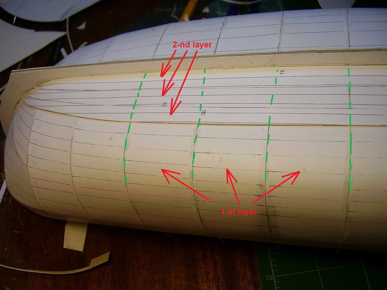
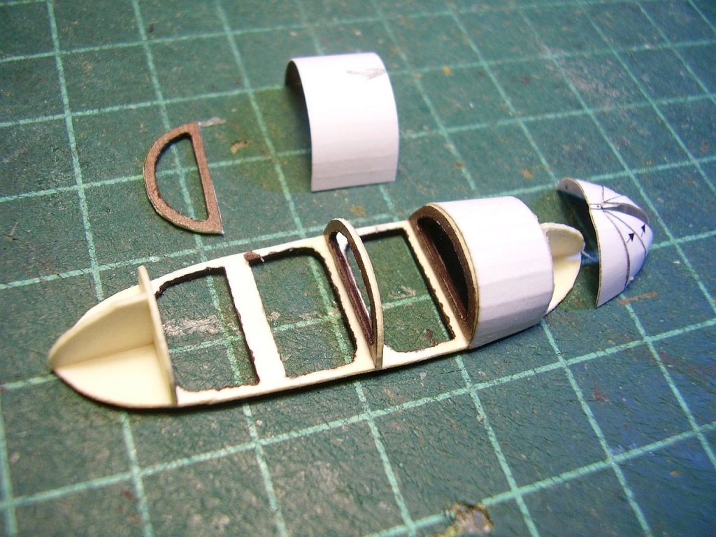
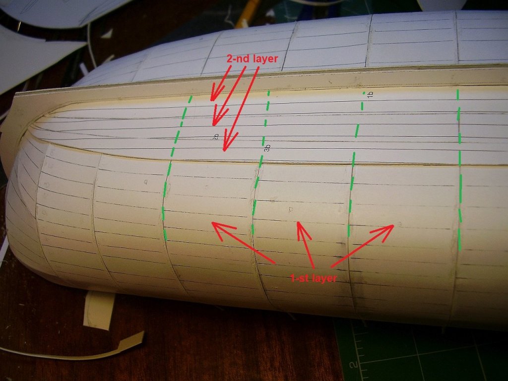
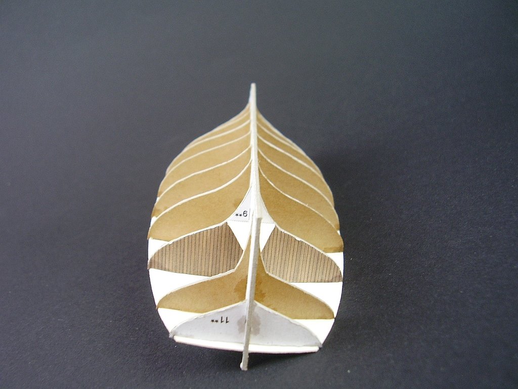
Sorry for my English, it is not perfect so... on the picture below you can see what I meant "the 1-st and 2-nd layers" and "frames". I put on glue only where green lines are. Then I apply glue on the whole face of the final planks (3-rd layer). Regards Tomek
-
Thank you Chris. the kit is going to be in "Modelarstwo Okretowe" (http://www.modelarstwookretowe.pl/index.php?p=21) and FB (https://www.facebook.com/modelarstwookretowe/?fref=gc&dti=103236332496&hc_location=ufi) Best
-
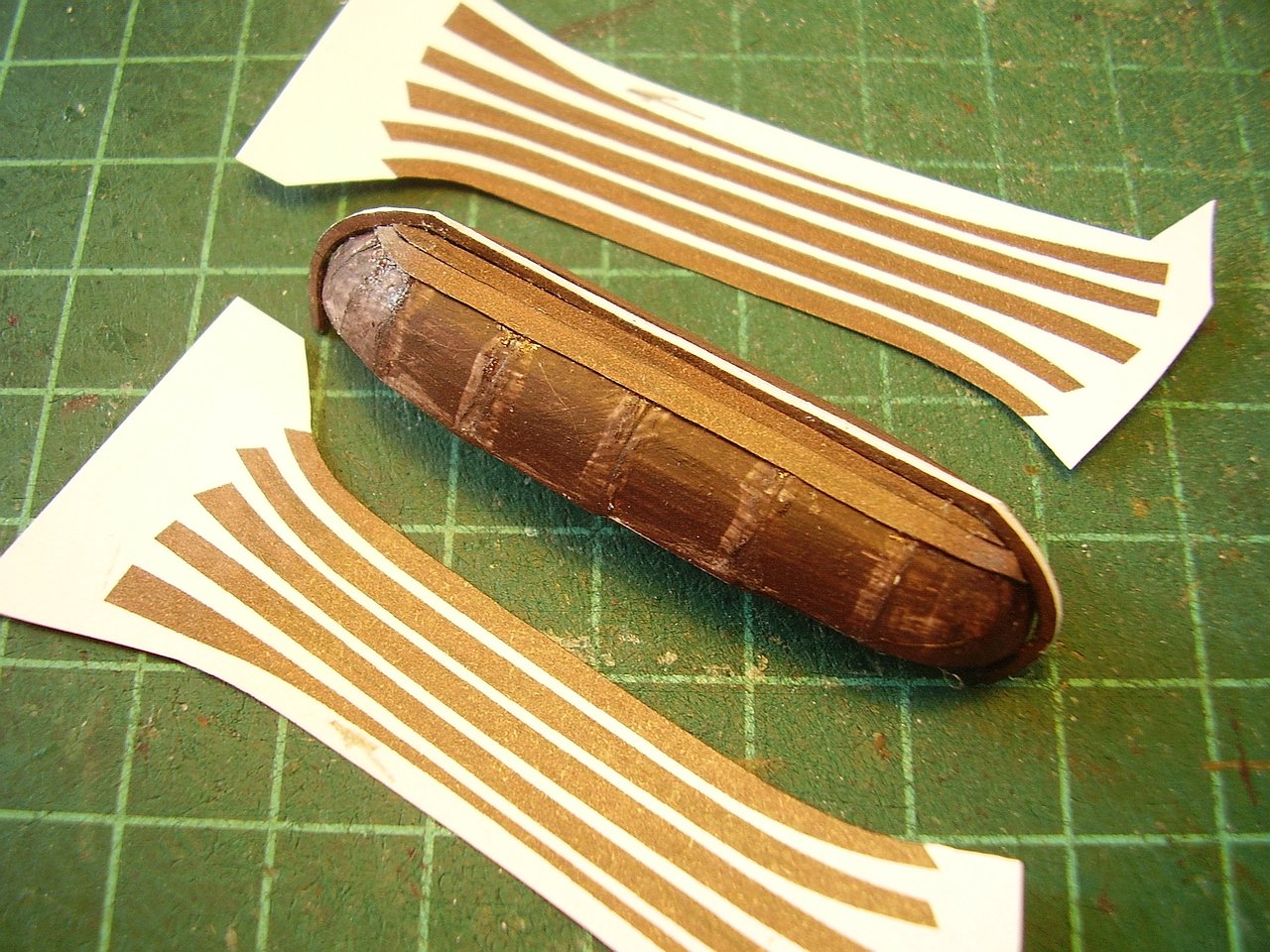
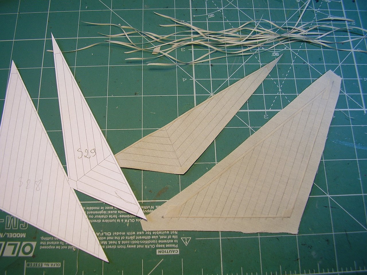
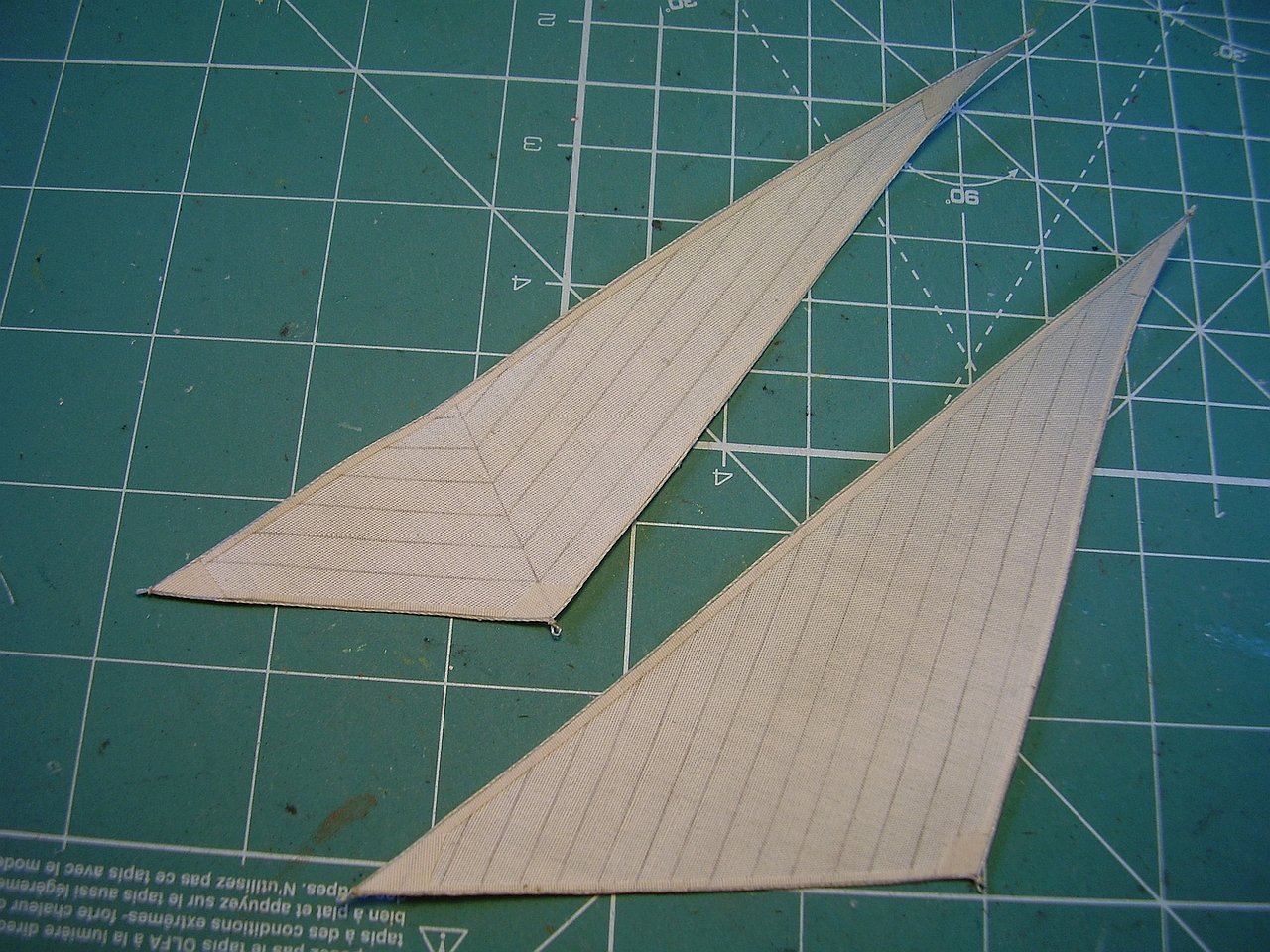
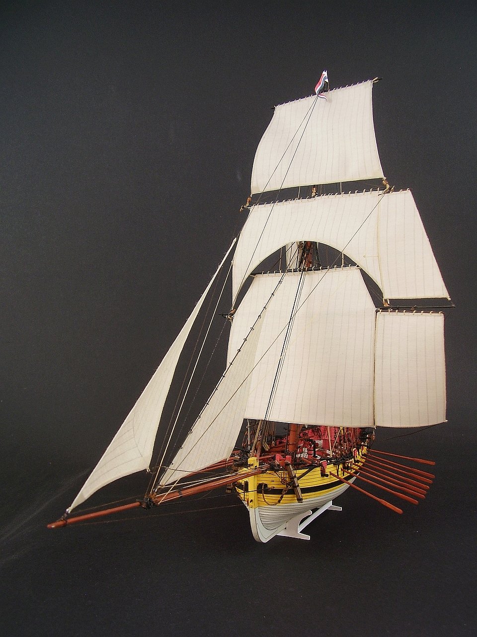
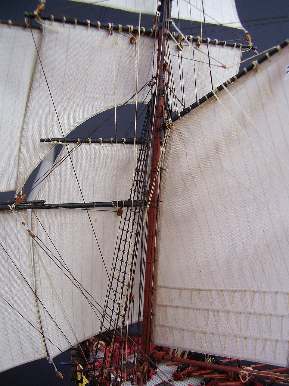
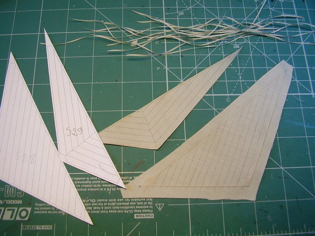
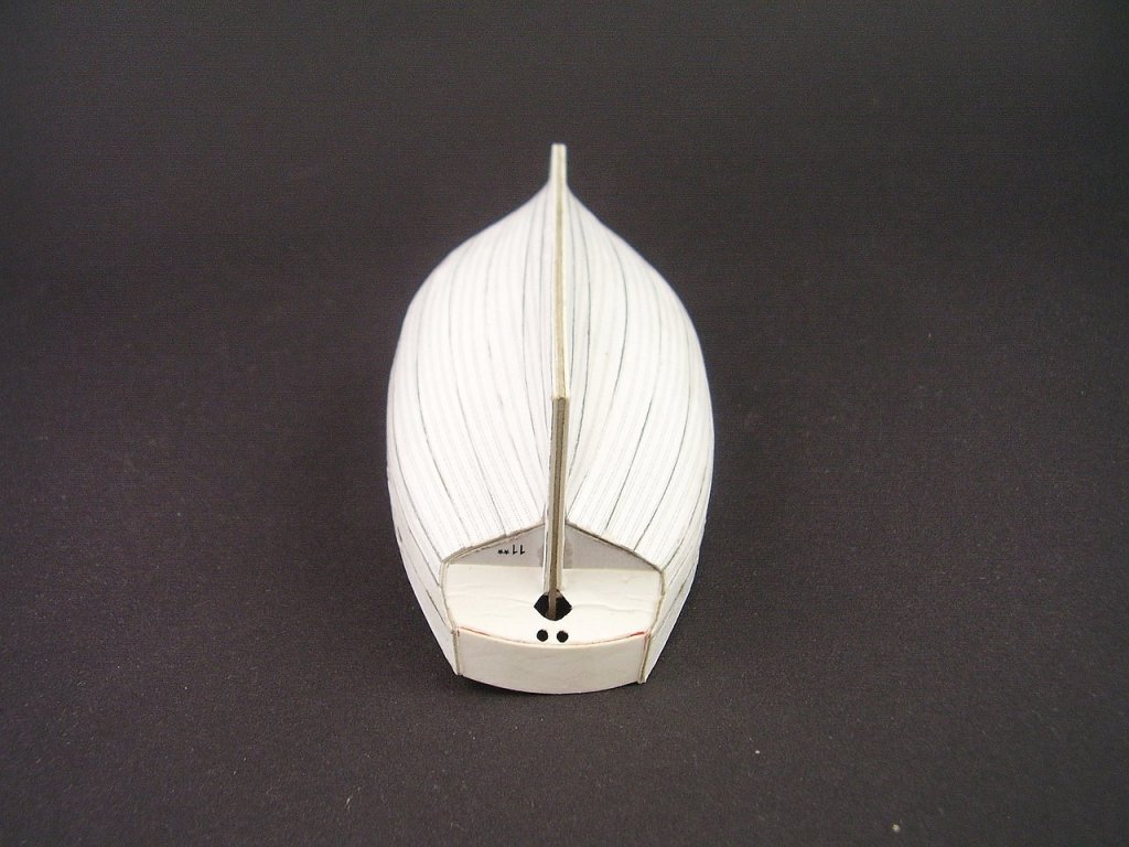
Dowmer, Thank you for appreciating. SAILS. I think, that in 1:100 scale any sewing is far out of scale, so I use only transparent glue (for wood for example Pattex). The material is batiste. I soak a part of it with glue and when it is dry I cut of long stripes. I glue them on the sketch of a sail. Then I cut out the sail and glue stripes on the other side. At the end I glue ropes and some cringles. Such sails are rather stiff (because of glue) but can be bent. Sometimes I use glue, water and hairdryer to give them the "windy" shape. Pictures below Regards Tomek


- 10 replies
-
- 11
-
-
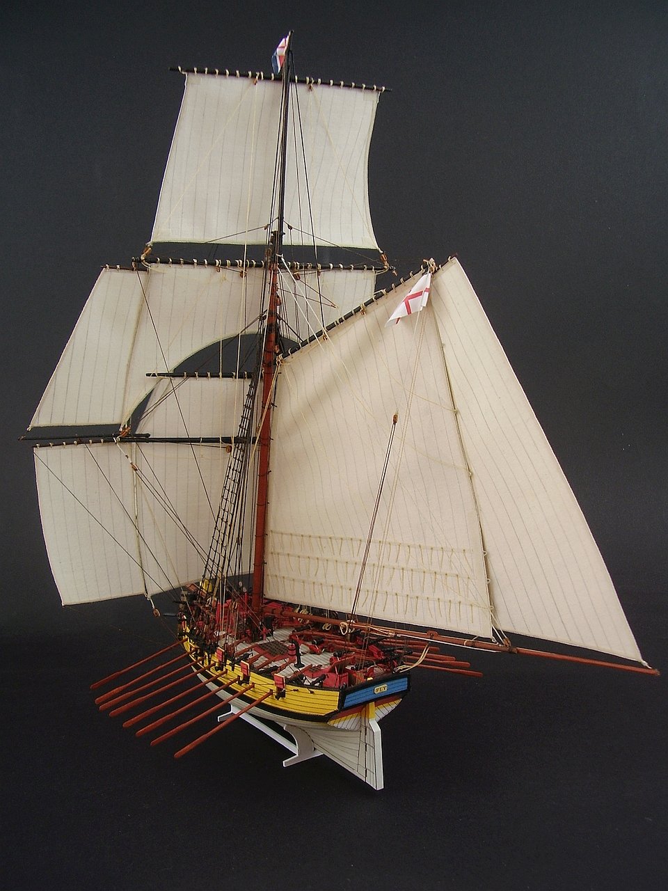
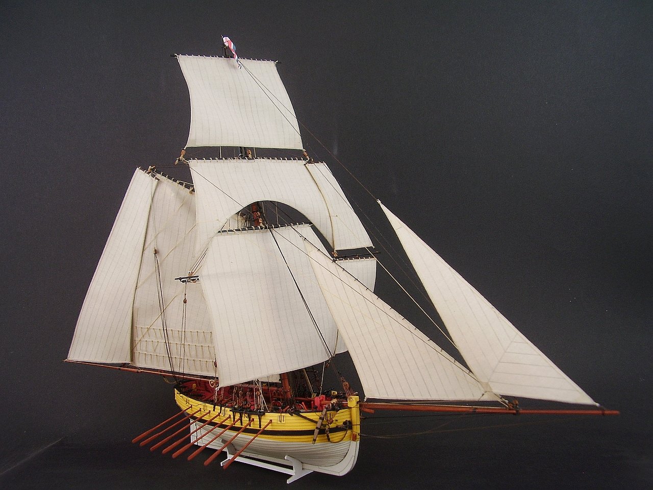
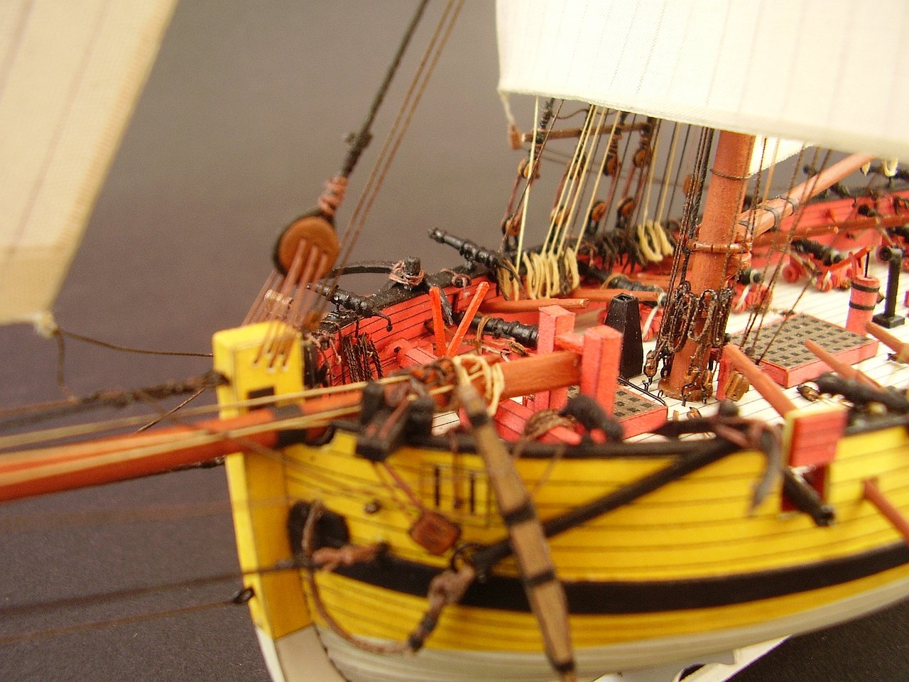
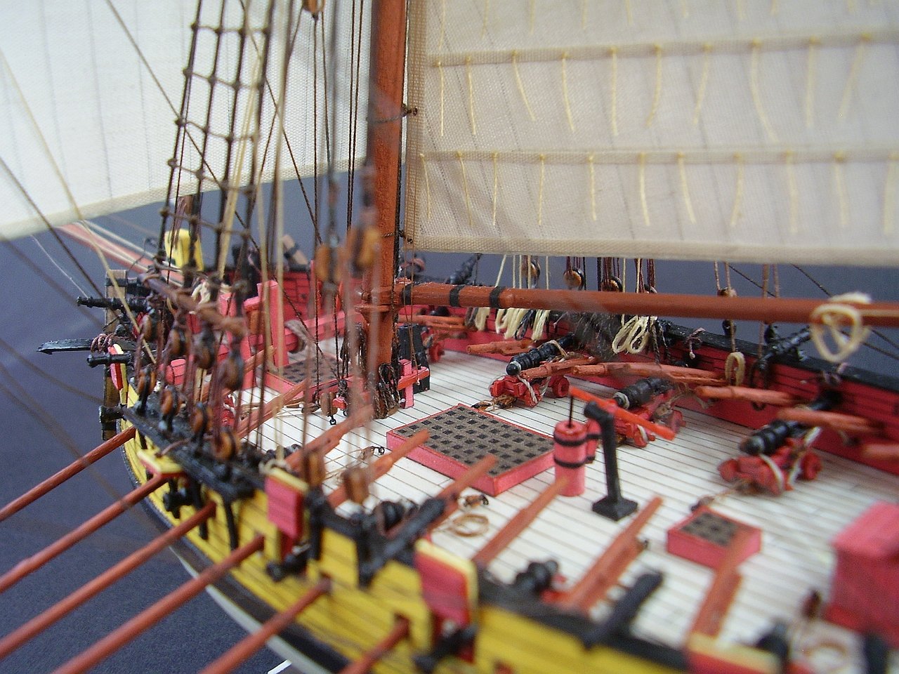
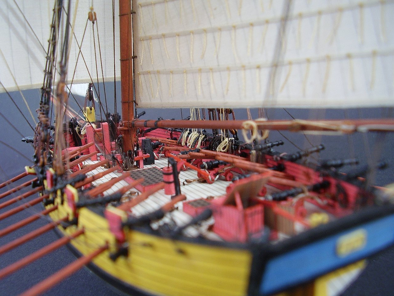
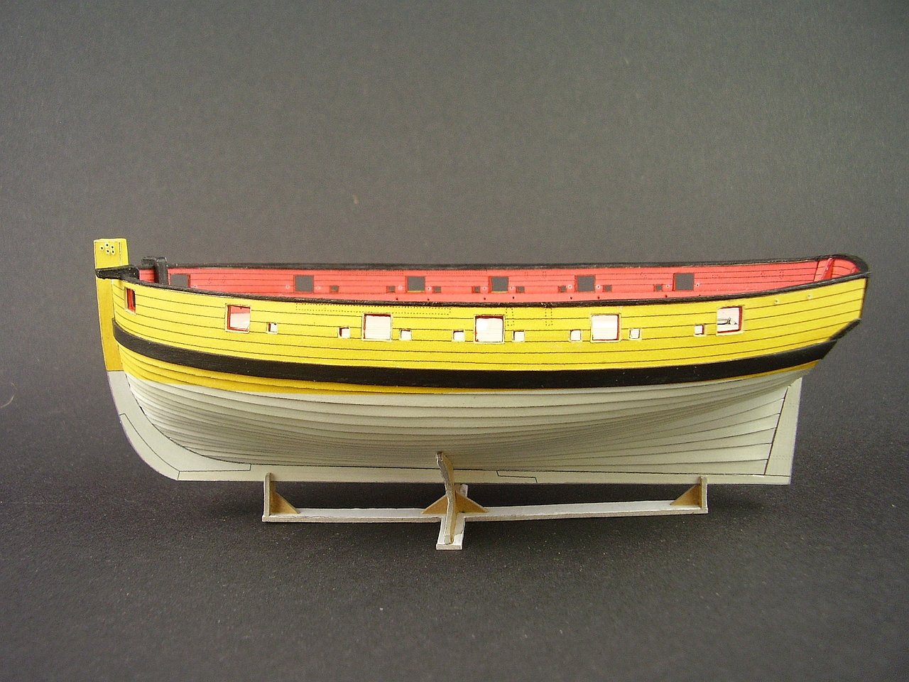
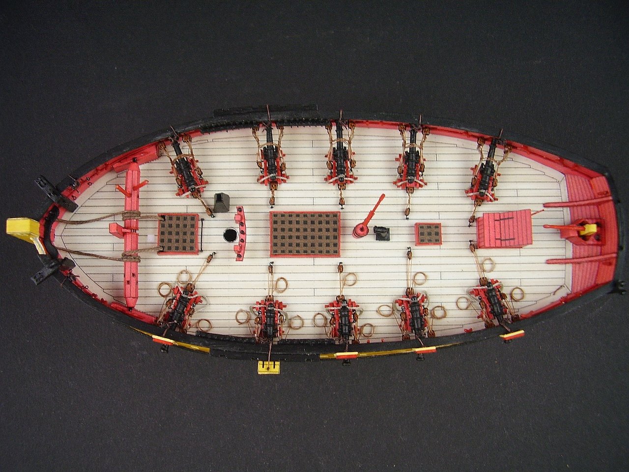
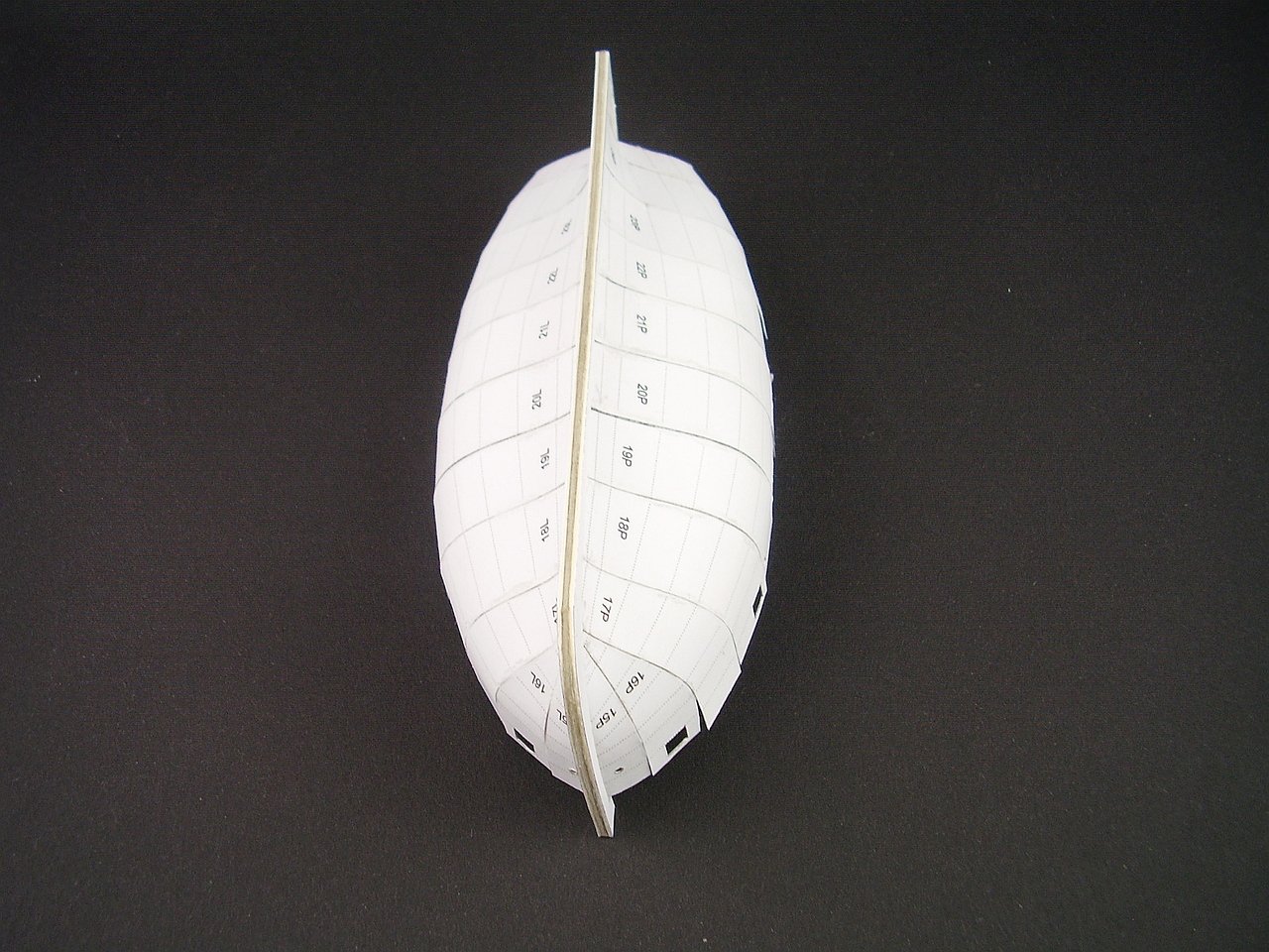
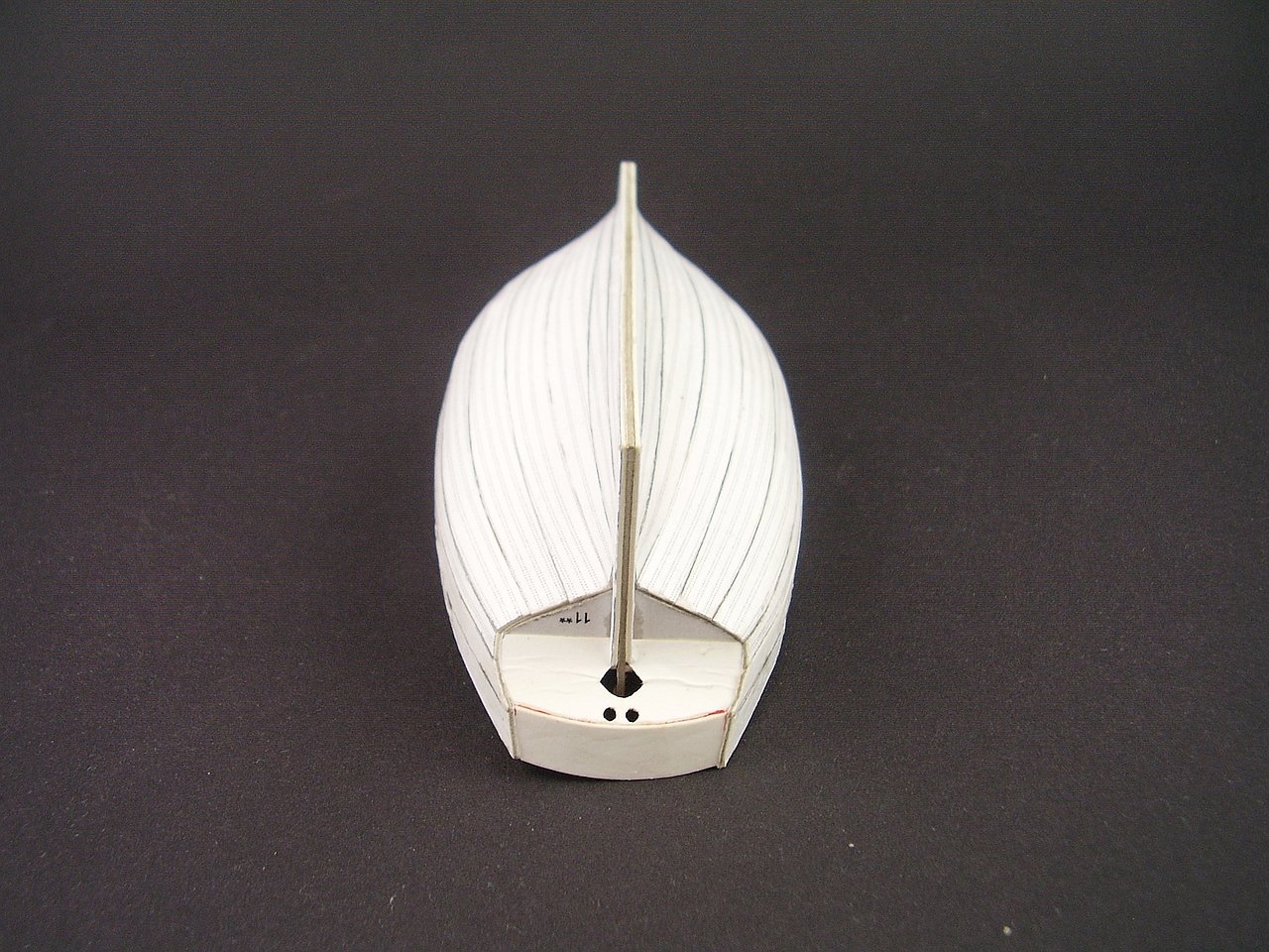
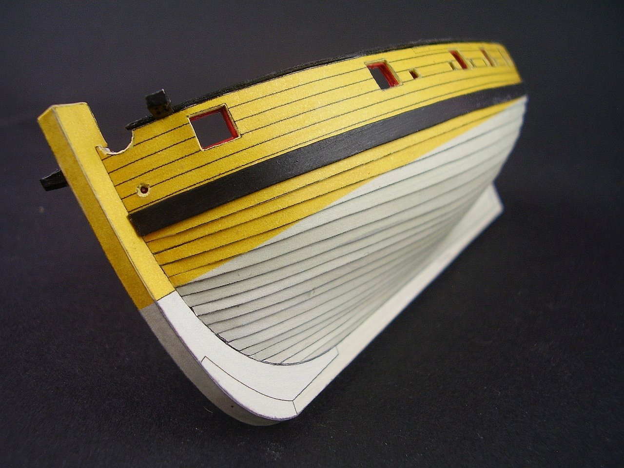
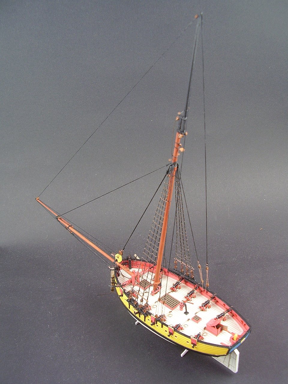
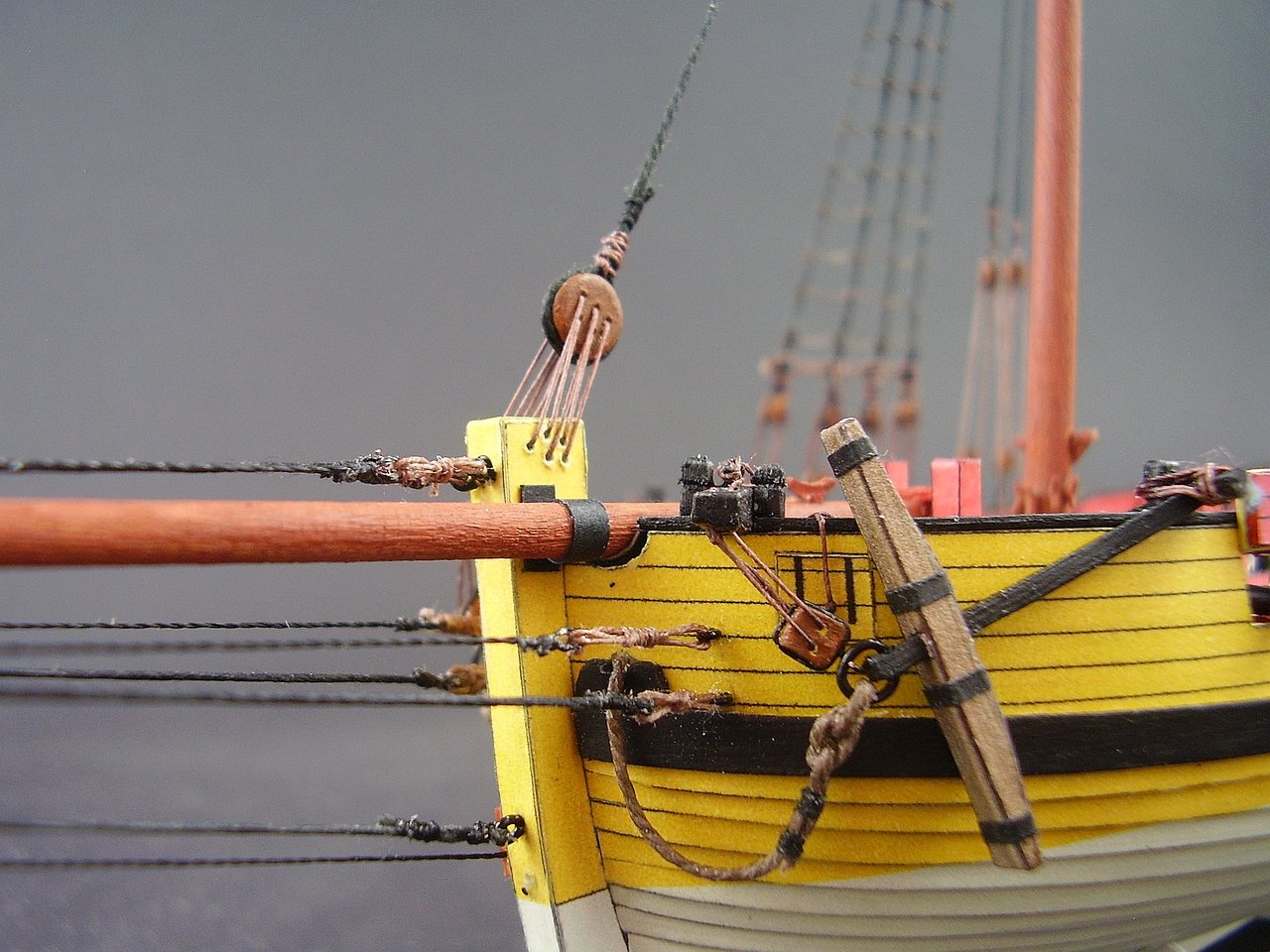
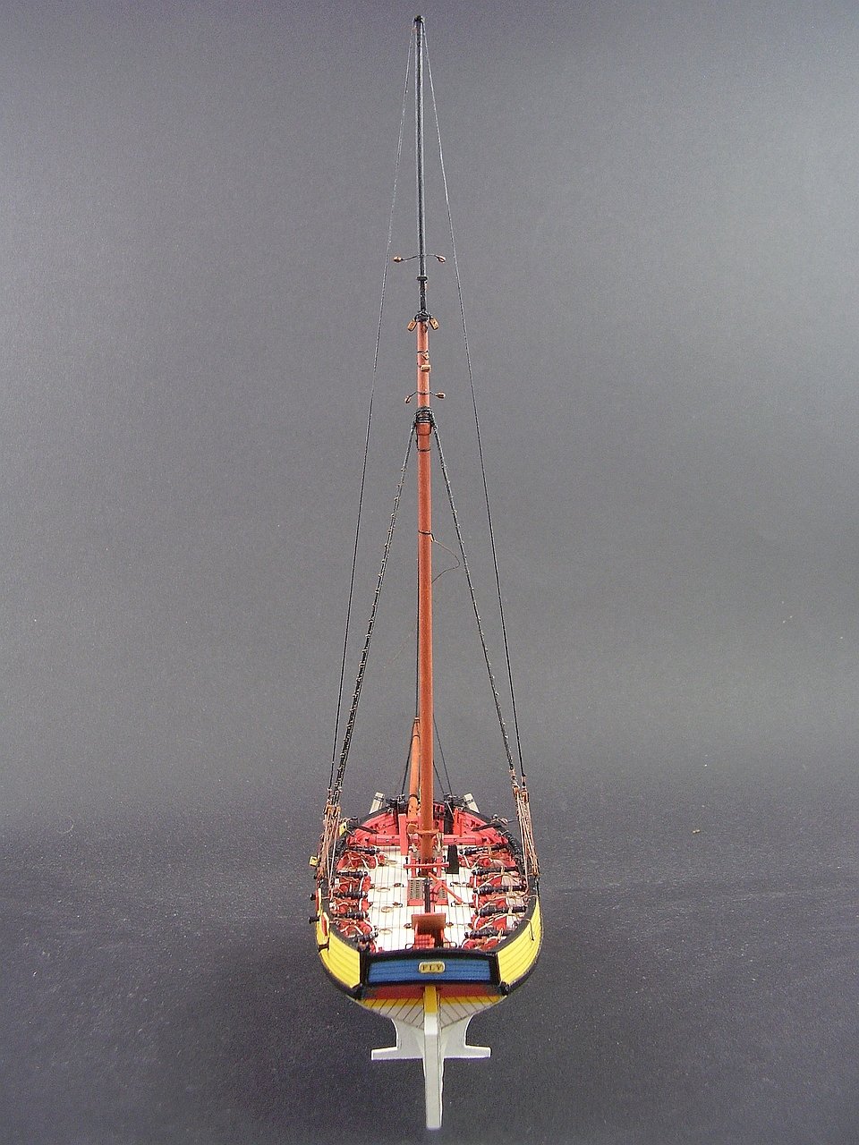
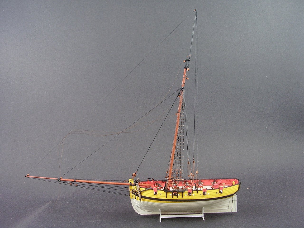
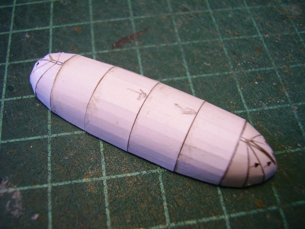
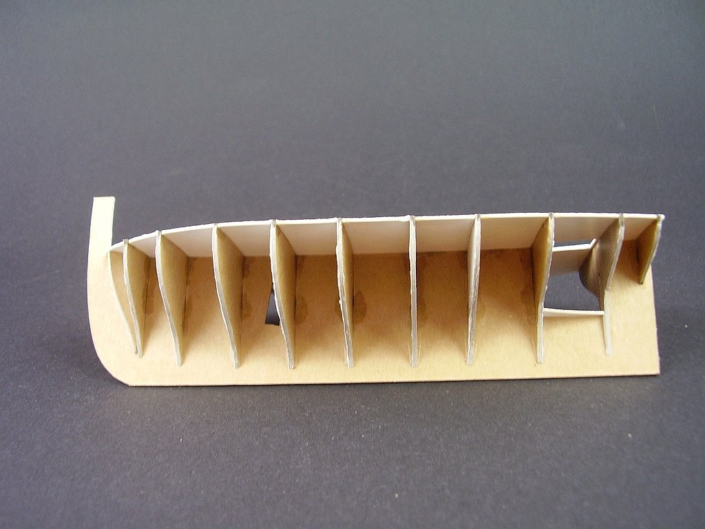
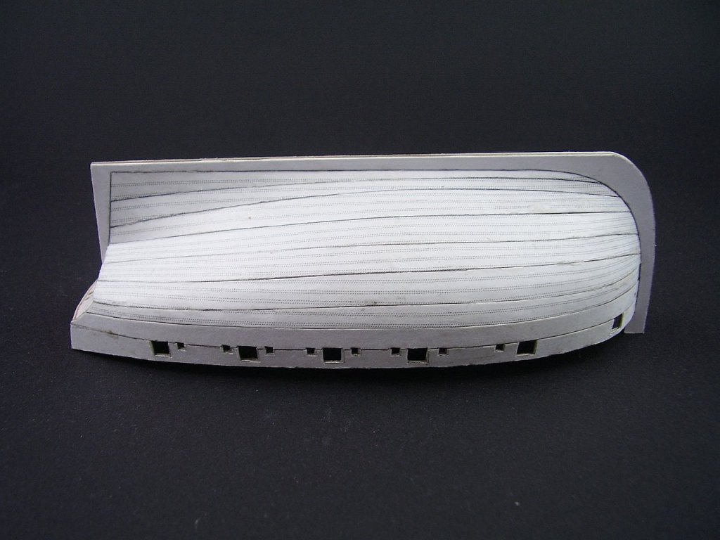
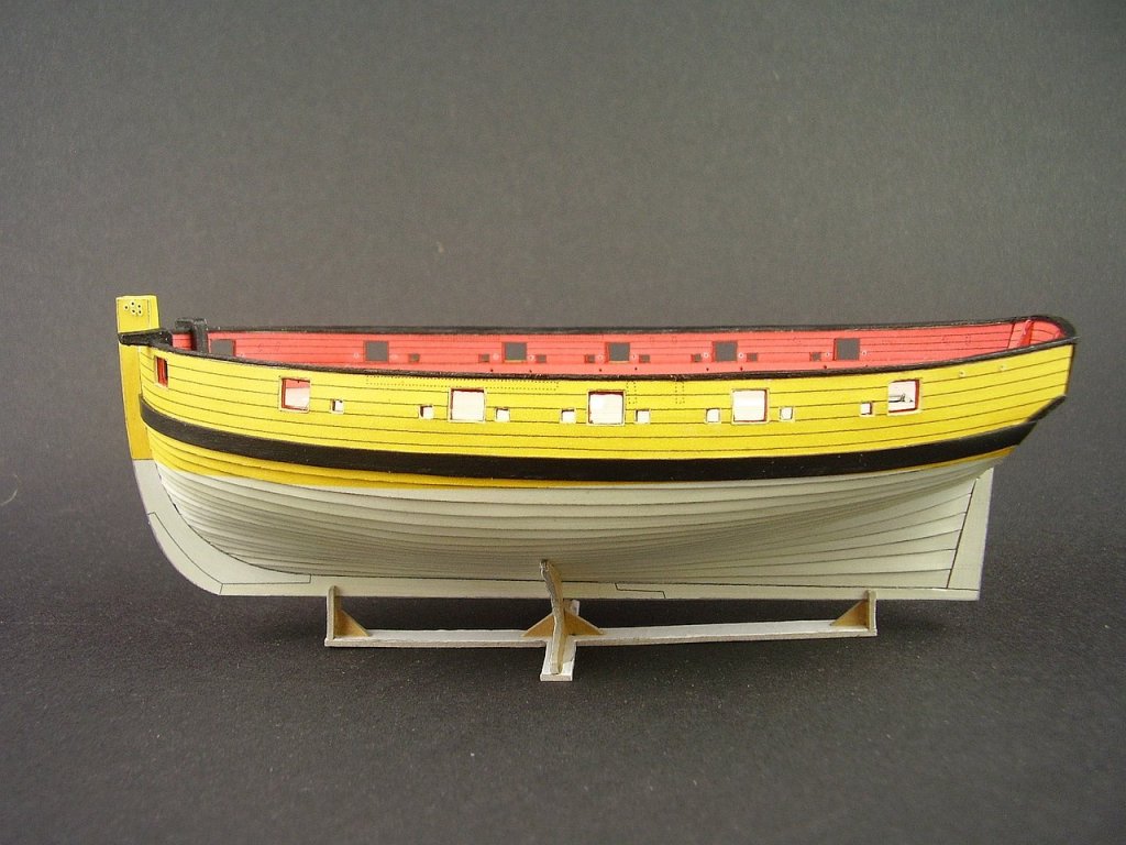
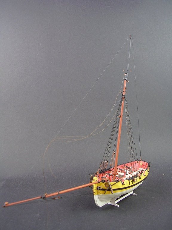
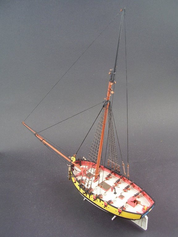
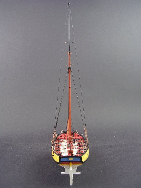
Greetings to all. My name is Tomek. For some time I have been working on my next card sail ship the British cutter HMS "Fly". I build my models only from paper and cardboard without painting (of course masts and rigging are made of wood and thread). I will honestly admit that "Fly" is my 20 cardboard model of a sailing ship so it looks much better than my first models from 15 years ago. The "step by step" how I design and build card sailing ships... 1. Frames made of 1mm card. The model is really small (about 16 cm long) 2. The first layer to strengthen and stabilize the hull 3. The second layer made of 0,5 mm card. The glue is applied only in places where the edges of the frame are located . Thanks to this the hull gets soft curves without visible "cow's ribs" ... 4. Attaching the third final layer on a well-prepared hull is a pleasure. 5. The deck equipment and artillery 6. The current stage - the mast and the bowsprit with standing rigging Regards Tomek


- 10 replies
-
- 21
-
-
Hi Chris, most of them were published by WAK, a Polish cardboard publisher: Grosse Jacht, HMS "Badger", muleta de Seixal, trabaccolo, Allege d'Arles and the last one Viking boat "Gokstadskipet". I also had one kit in "Modelarstwo Okrętowe" - HMS "Speedy". As I'm a "paper" modeler, you can find some of my work on "paper" forums like "Papermodelers.com" as Seahorse. Regards Tomek
-
Greetings from Poland. For many, many years I have been designing and building small sailships from cardboard, some of them even appeared as kits, so I am convinced that the MSW forum is a place for me. Now I am working on the British cutter HMS "Fly" Best Tomek