

halituzun
-
Posts
137 -
Joined
-
Last visited
Content Type
Profiles
Forums
Gallery
Events
Posts posted by halituzun
-
-
1 hour ago, Mic_Nao said:
Nice work, not easy at this scale.
Thanks a lot Mic_Nao....
-
My first and only purpose for posting this blog was to be helpful to the ongoing or future builders of this model. During my build time to access to detailed build logs was very limited. I hopes the blog serves as it was intended to.
This was my third ship model, but the first with sails and proper rigging. All the methods I used during this build are not the only ones and maybe not the correct ones. I made a lot mistakes . But mistakes also teach you. At least tell you what not to do the next time.
I thank all the viewers, likers and commenters. Your interest is much appreciated .
Happy and healthy modeling days to you all....
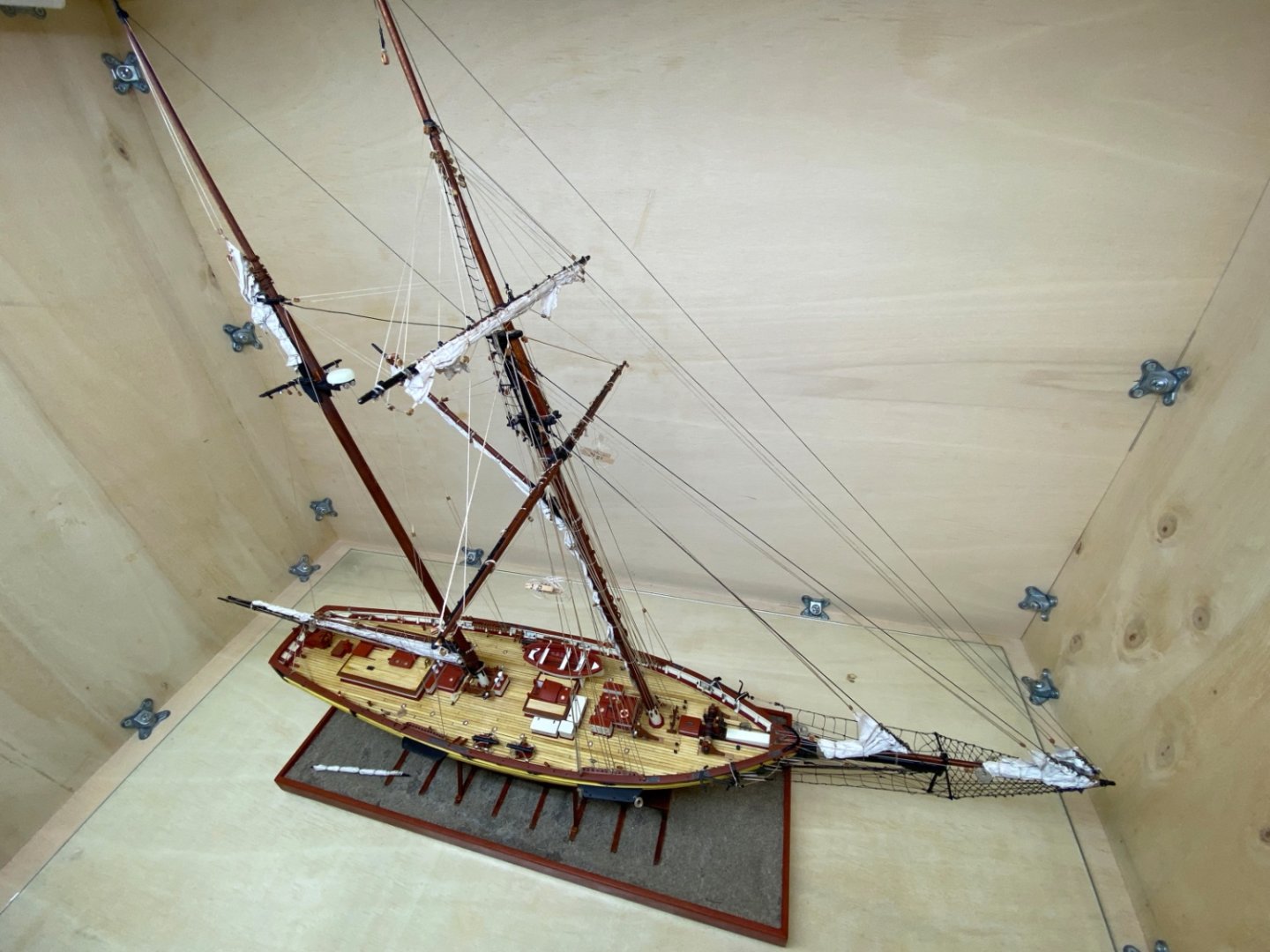
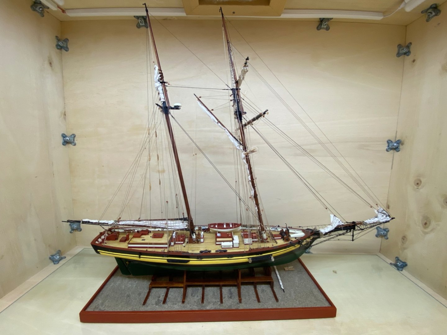
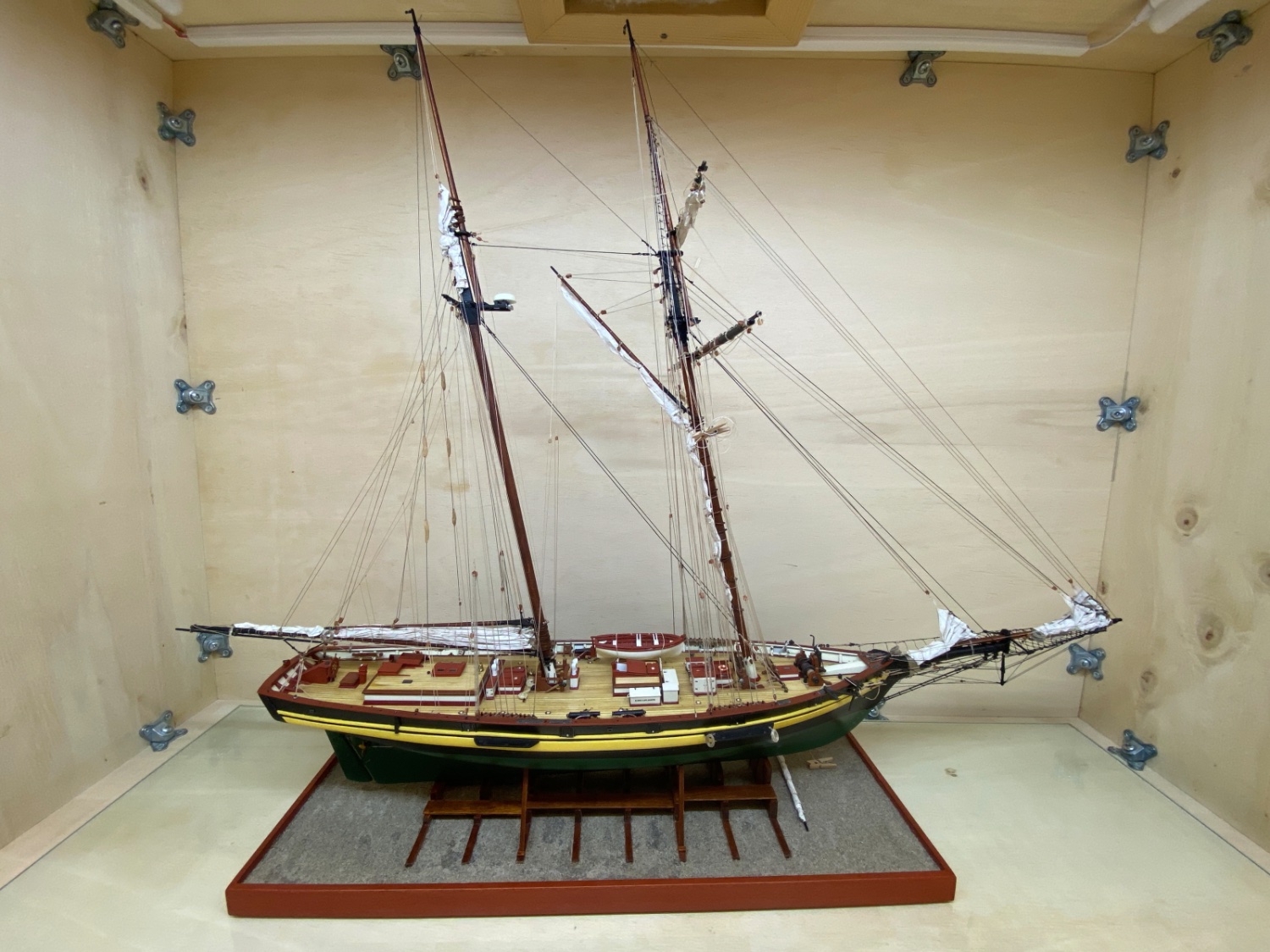
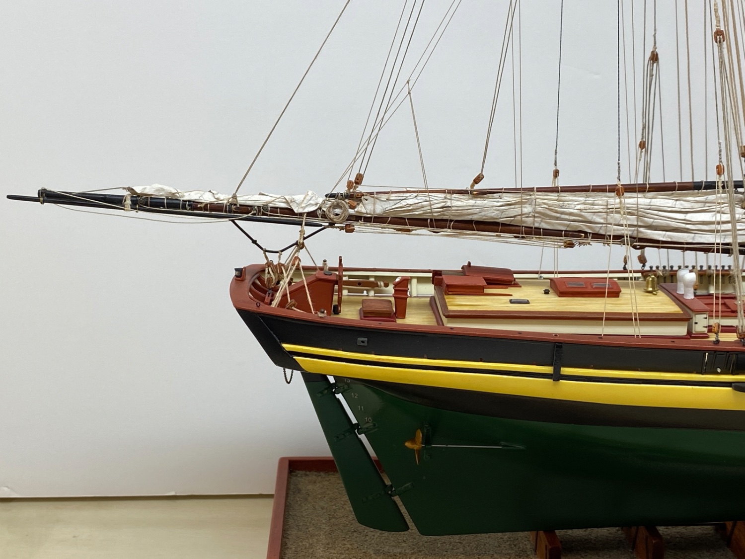
PS : Finished photos can be viewed ın the link below
https://modelshipworld.com/gallery/album/2633-pride-of-baltimore-ii-by-halituzun-model-shipways-164/ -
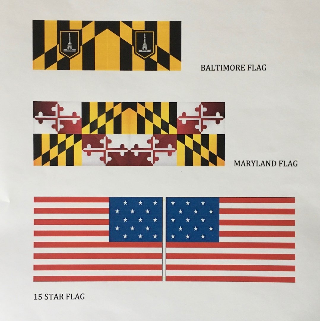
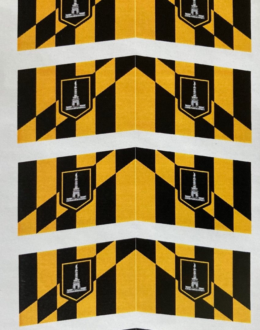
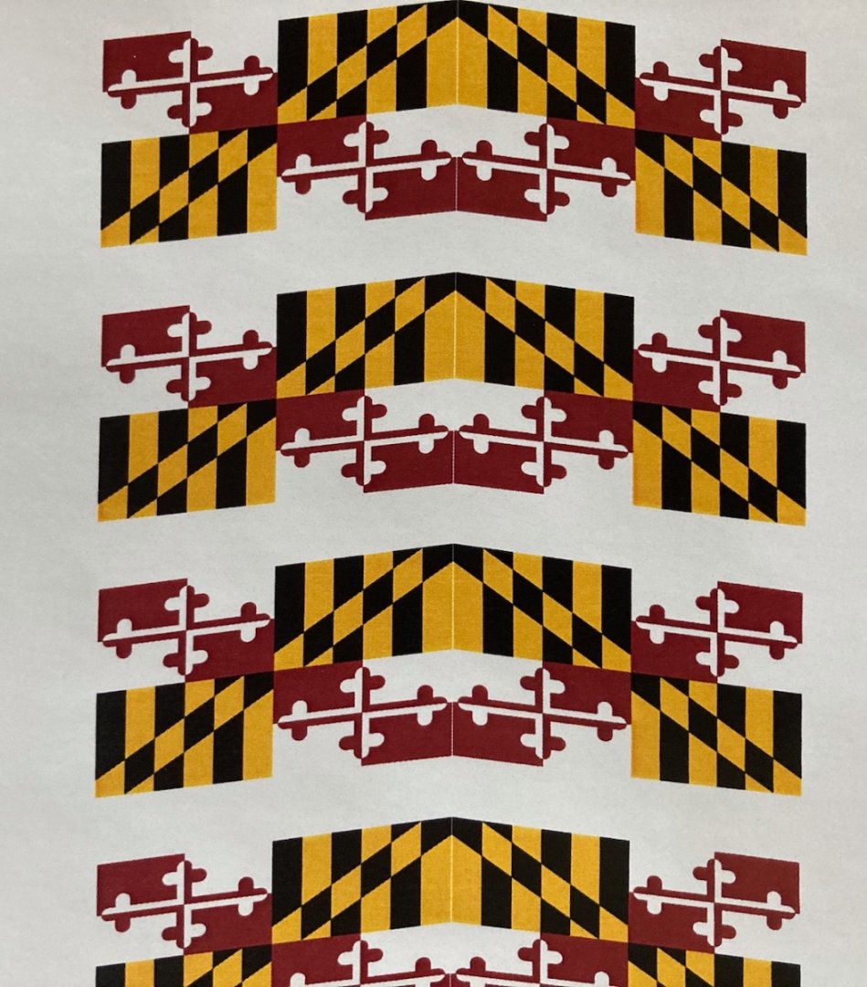
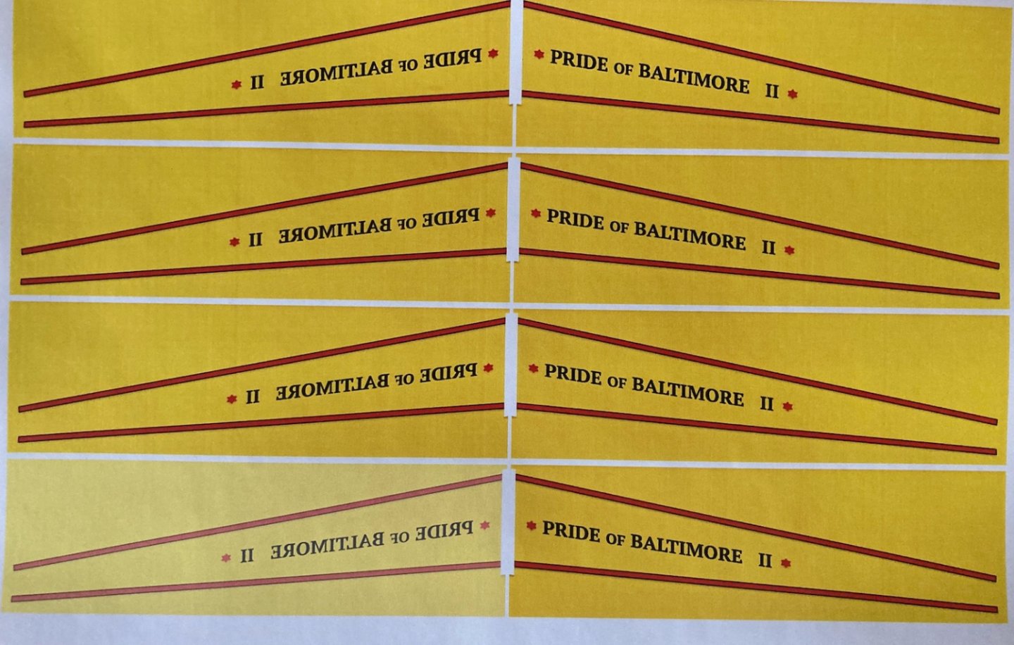
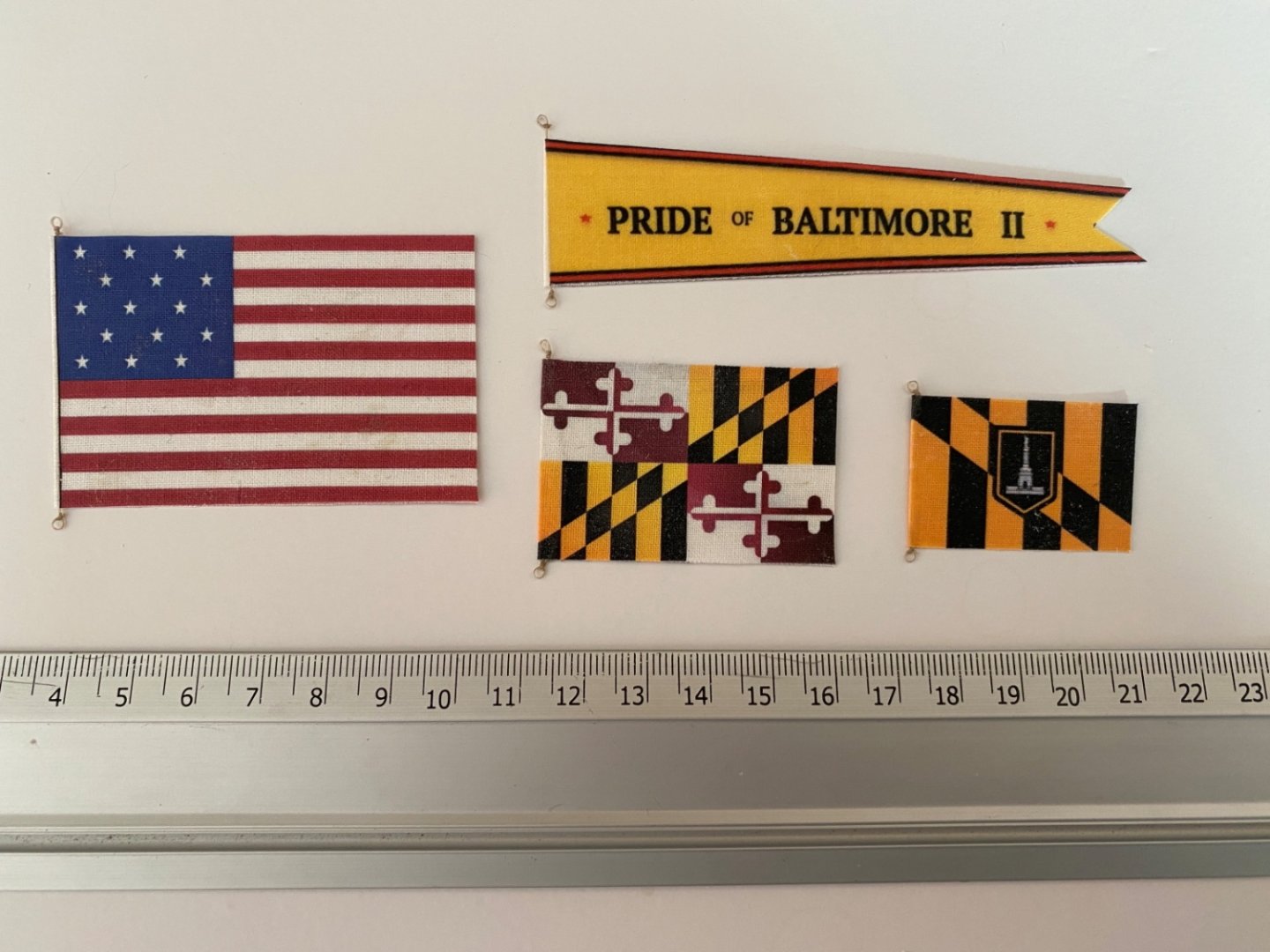
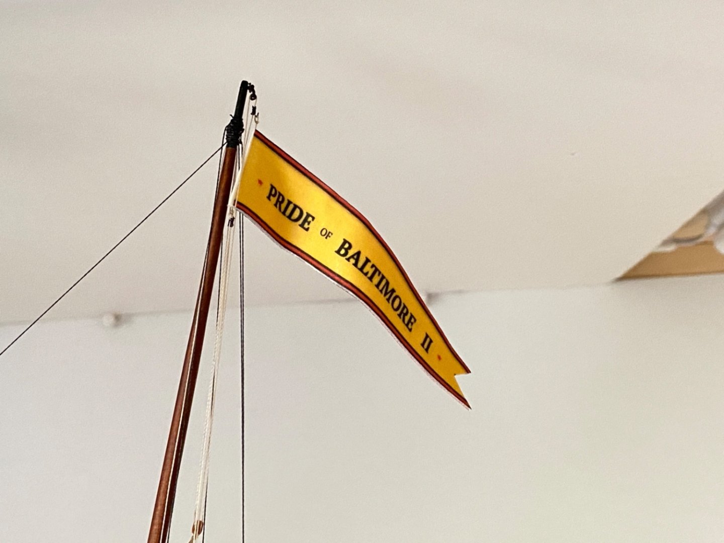
The last step of POB II build was the installation of the flags and ship's pendant.
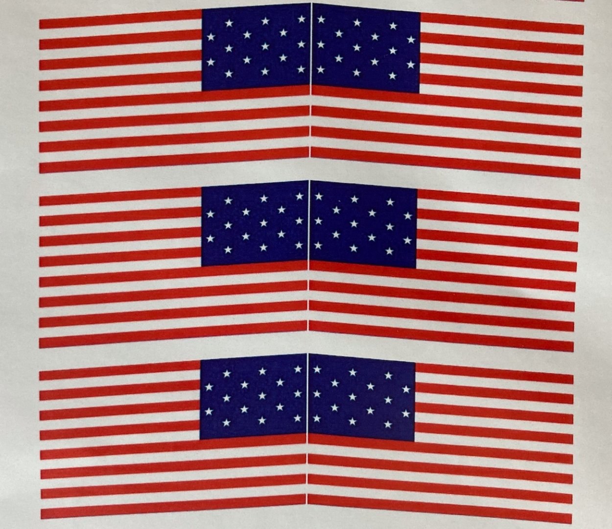
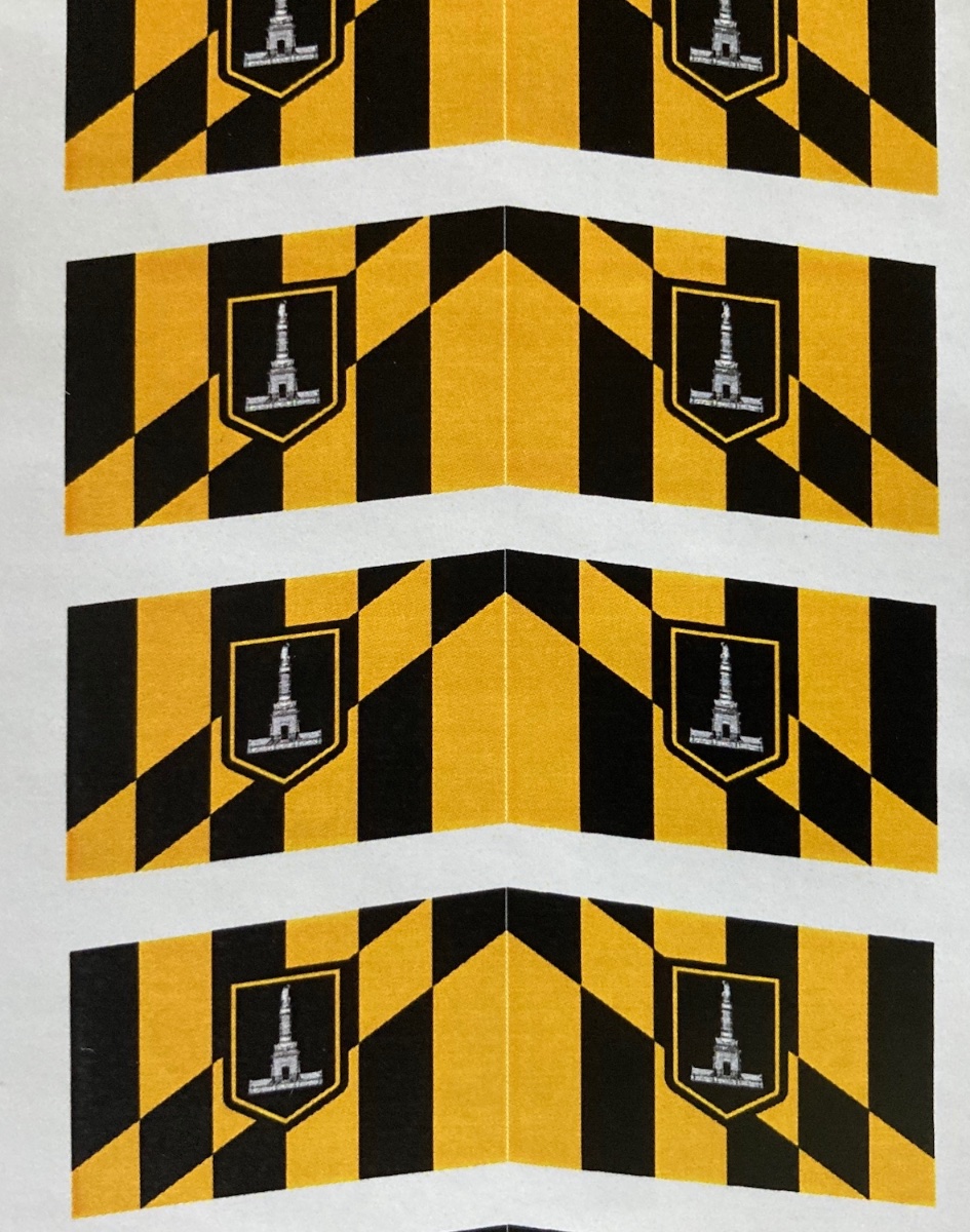
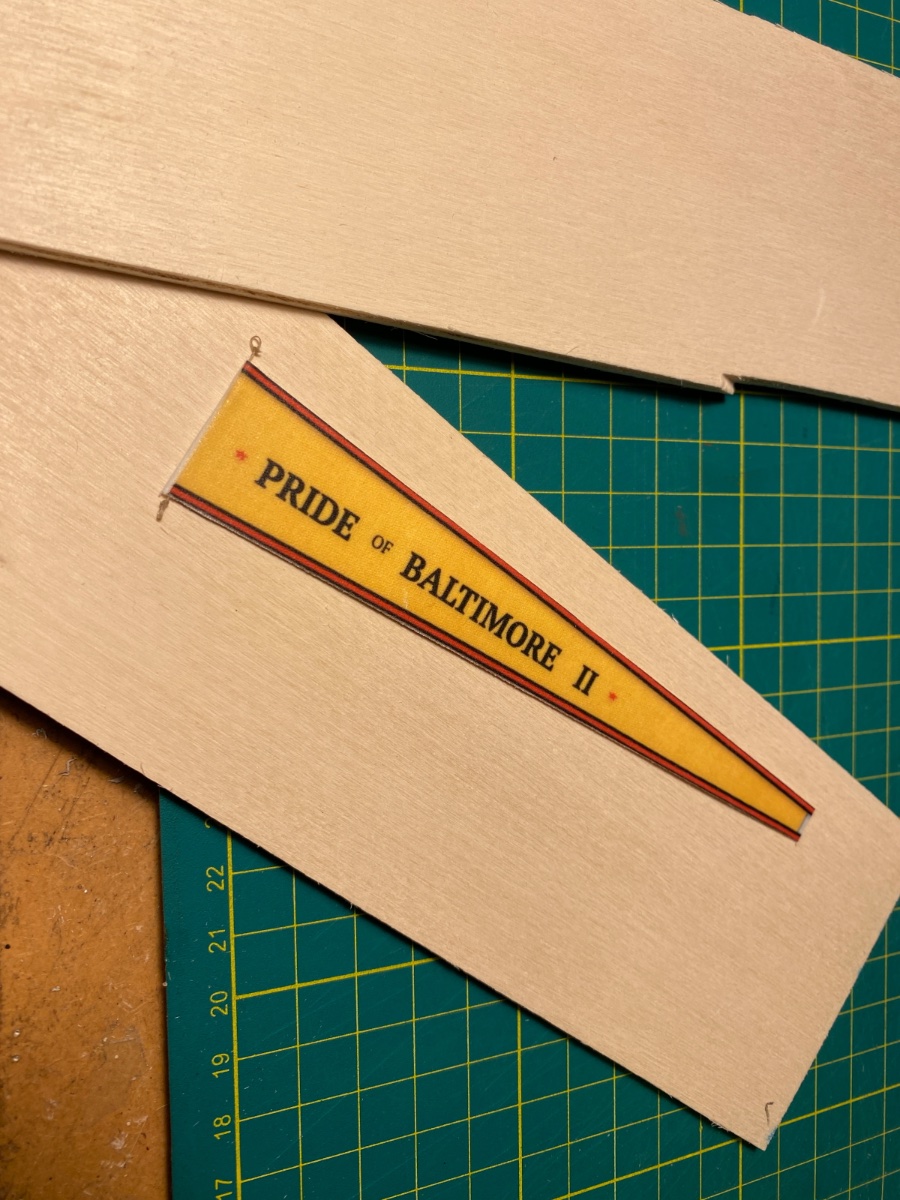
The flags and the pendant were prepared before. Flag photos were retrieved from internet. Pendant was designed, drawed and saved as a picture using MS Powerpoint. Using 'format picture' in MS word and discovering its 'skew' function even drooped like pictures of the flags produced. Prints on several kinds of paper were made in the print shop and put aside.
Paper prints
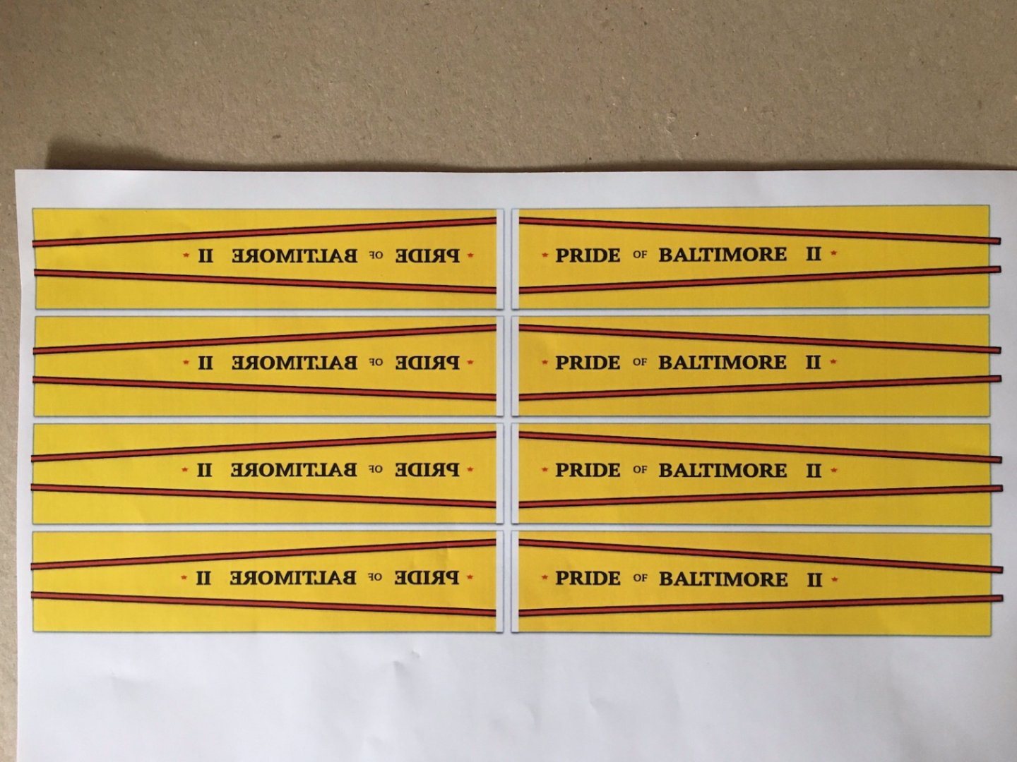
Skew function results
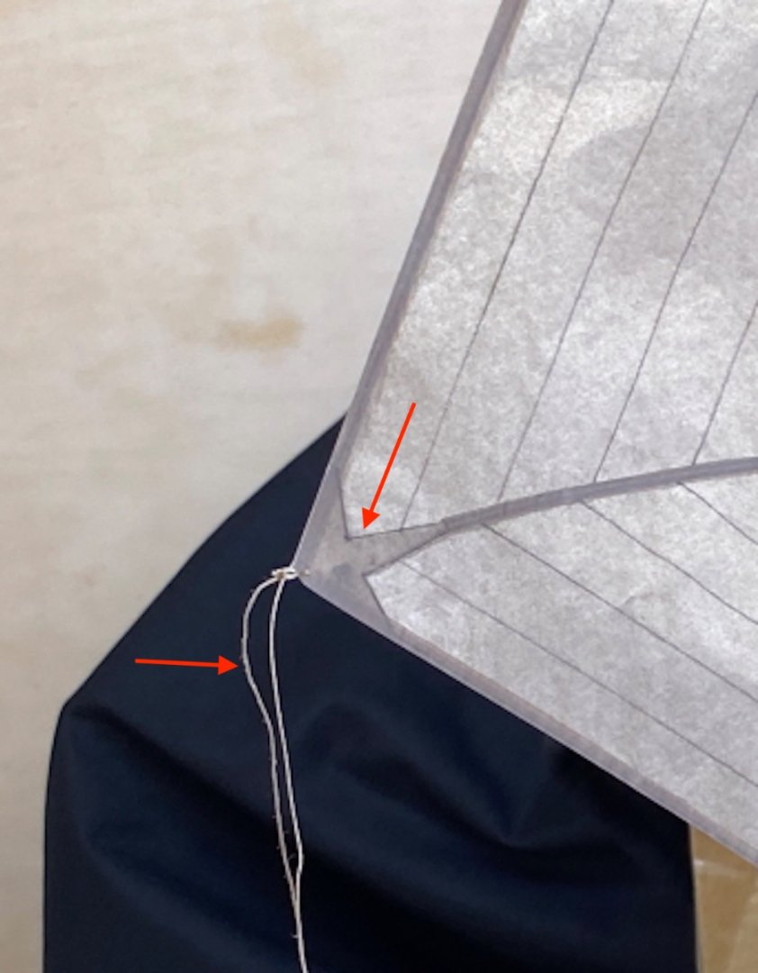
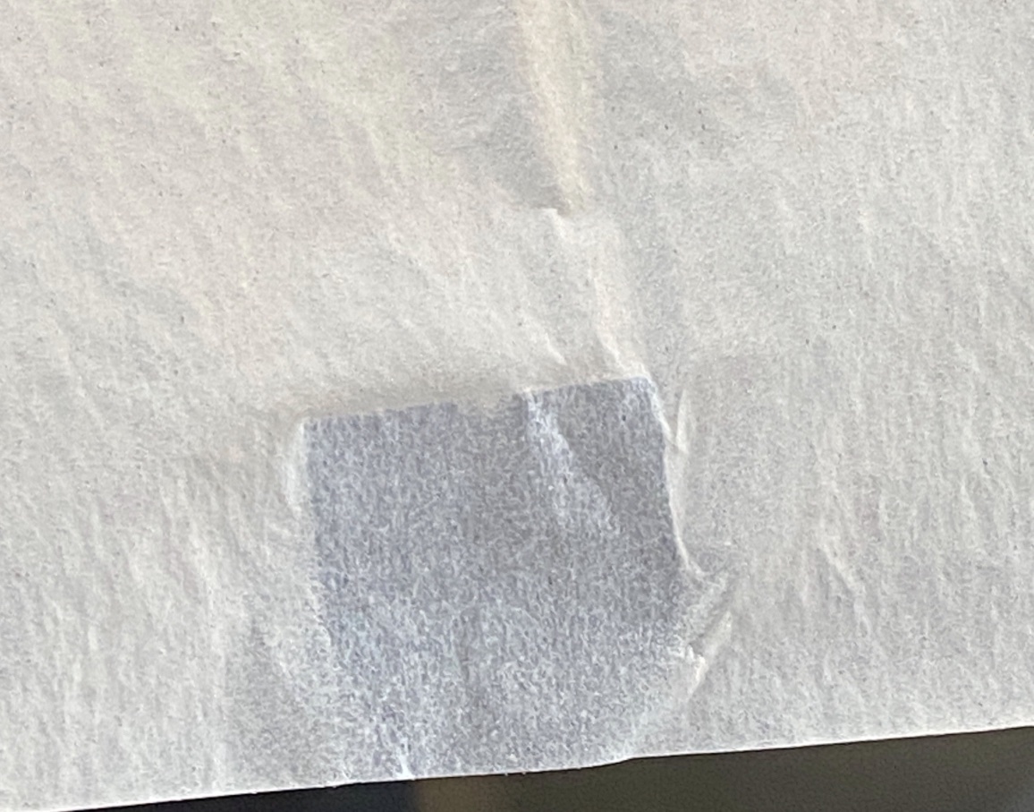
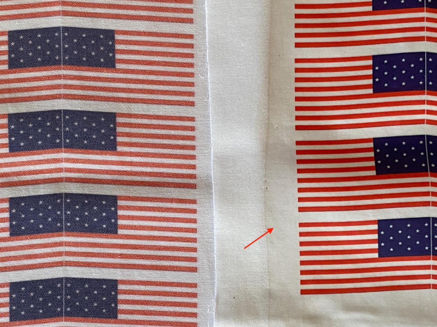
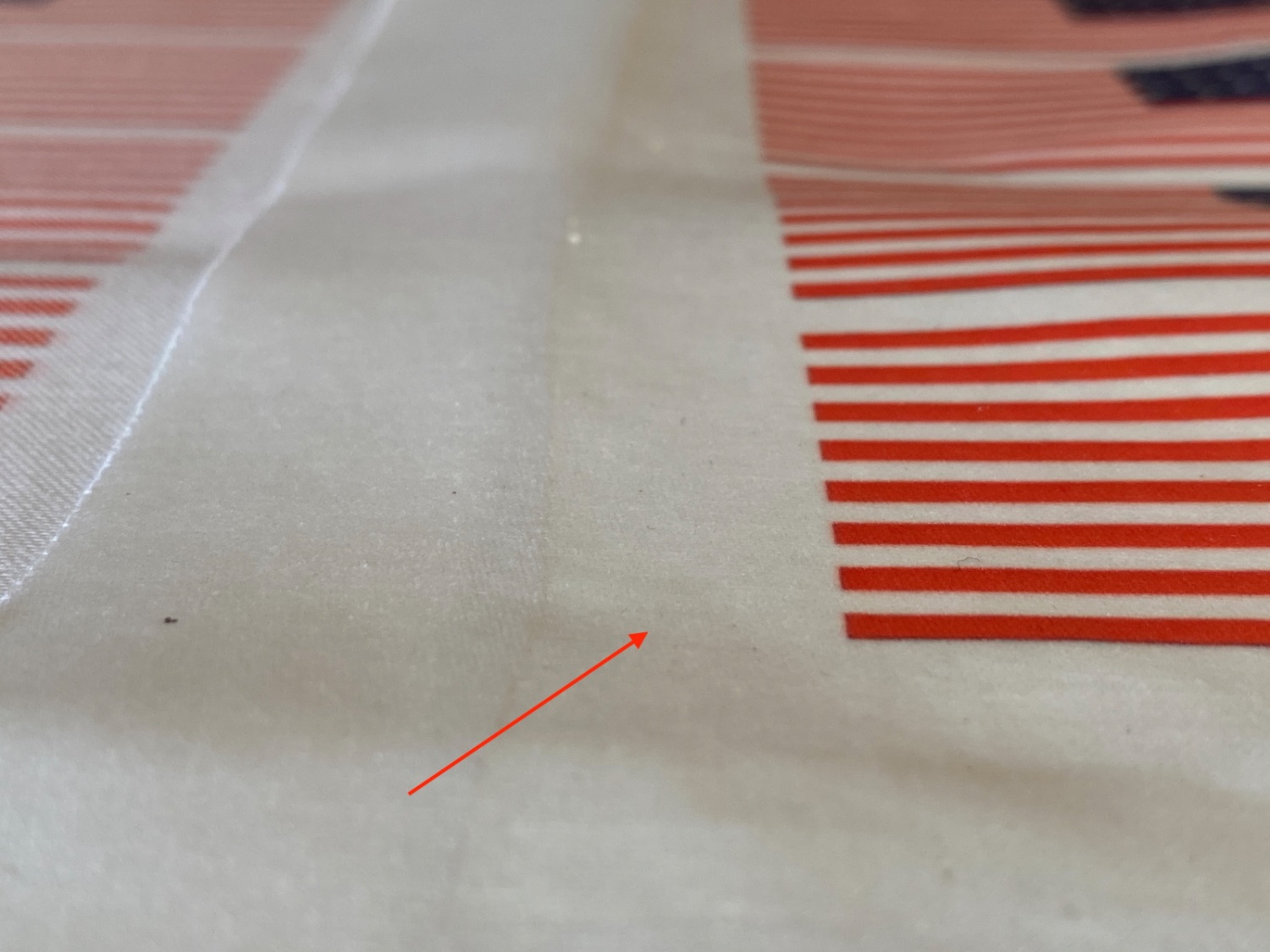
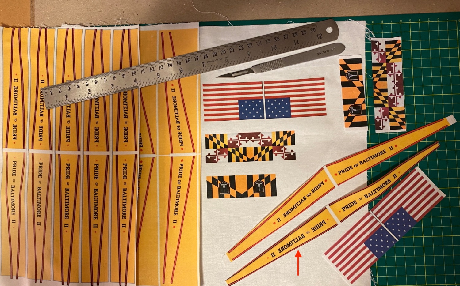
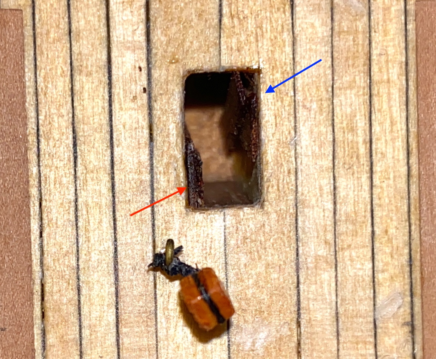
Then the manager of the print shop suggested to print on cloth. Here the important factor is the choice of cloth type. The best is silk (which was not thought by me or manager at that time) and quality cotton or linen with dense weaving follow. There are two methods of printing on cloth ( as the manager said) : direct transfer or sublimation. Here is photo showing the difference between them. Red arrow indicates the direct transfer sample.
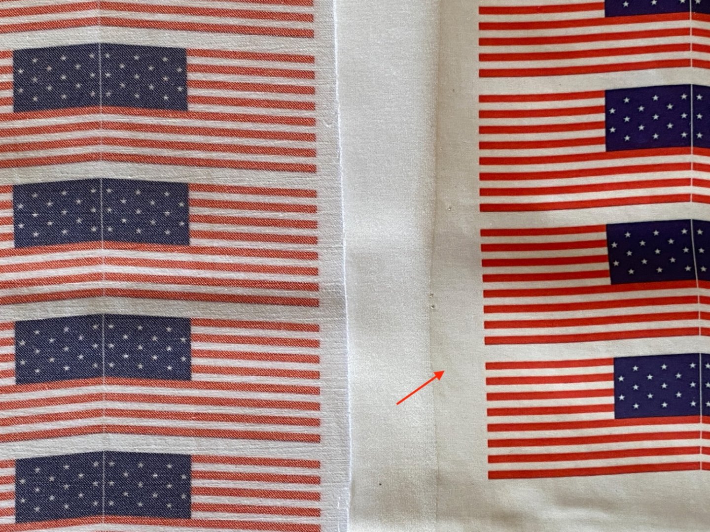
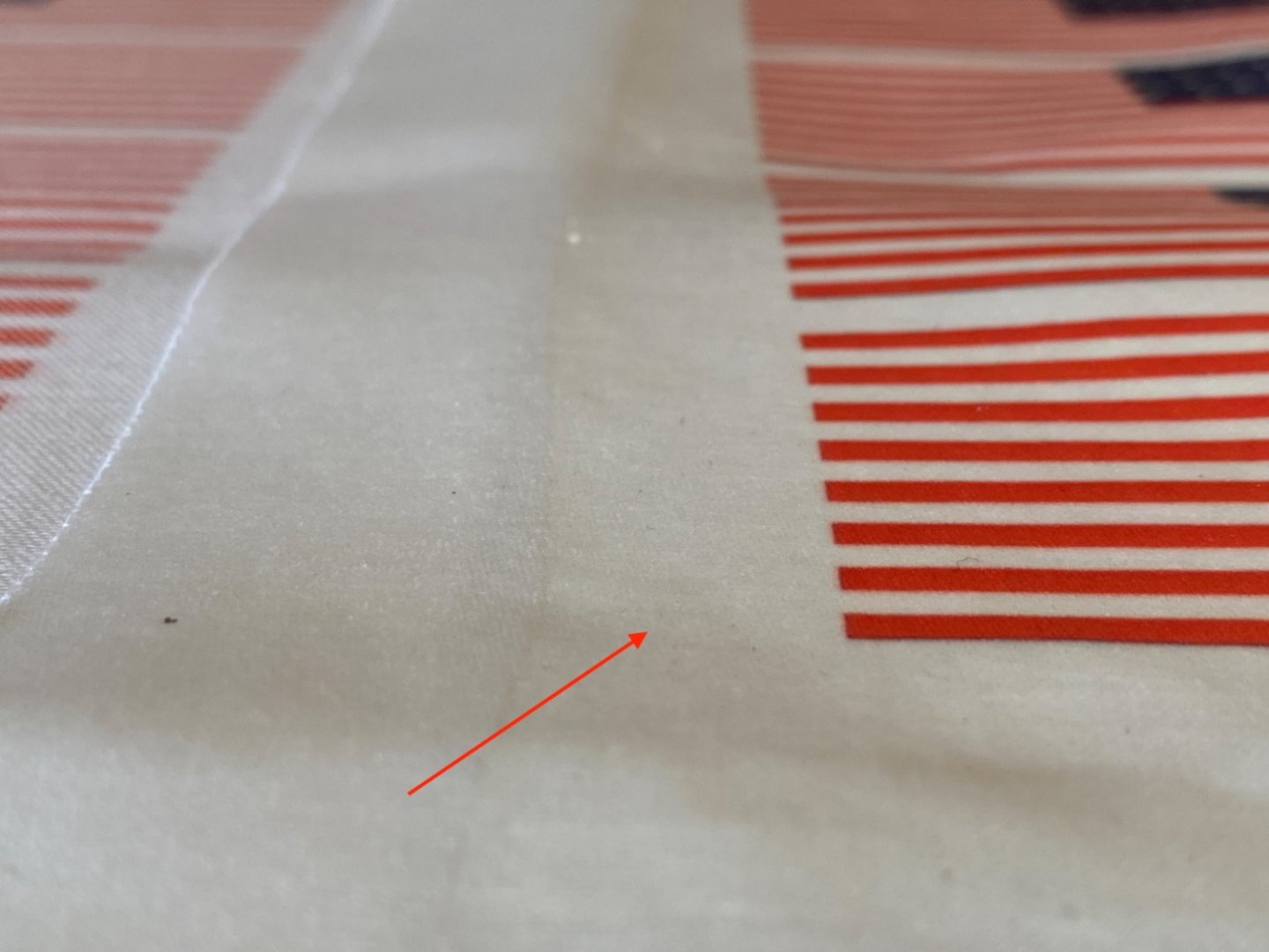
Sublimation method
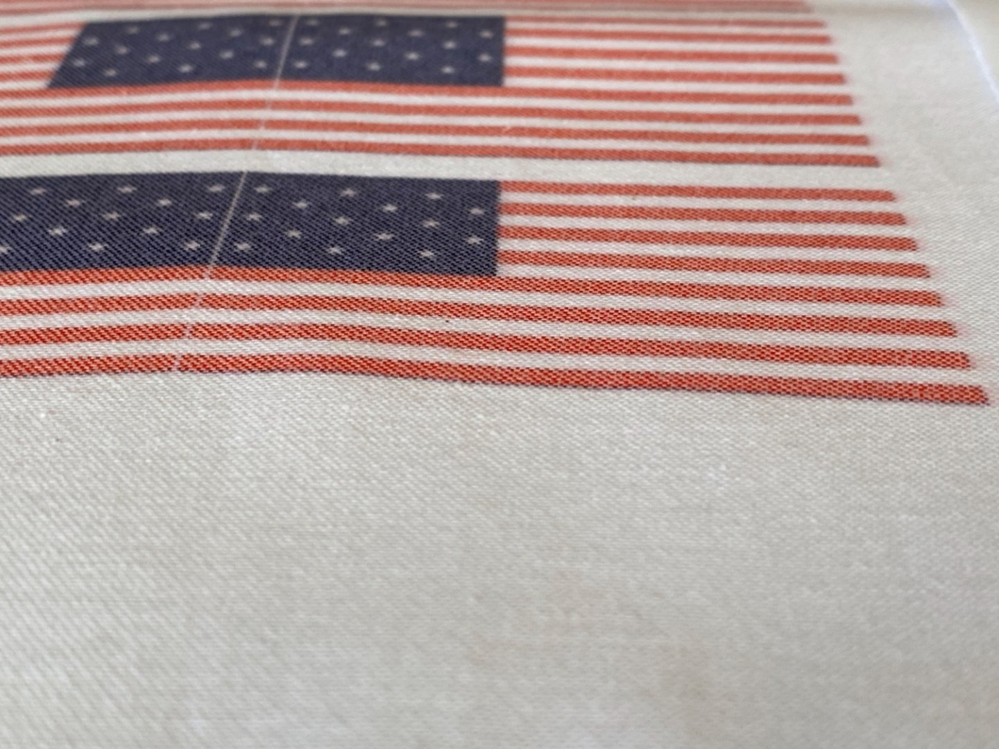
Printing by direct transfer creates a layer on the cloth and thickens it. In sublimation method the dye diffuses into the cloth and looks more natural to eye. The colors look pale in this method , however with adjustments done before and during printing may solve it. After all printing to cloth was not a routine daily job for the print shop and I am sure they can develop the method and output quality if demand increases.
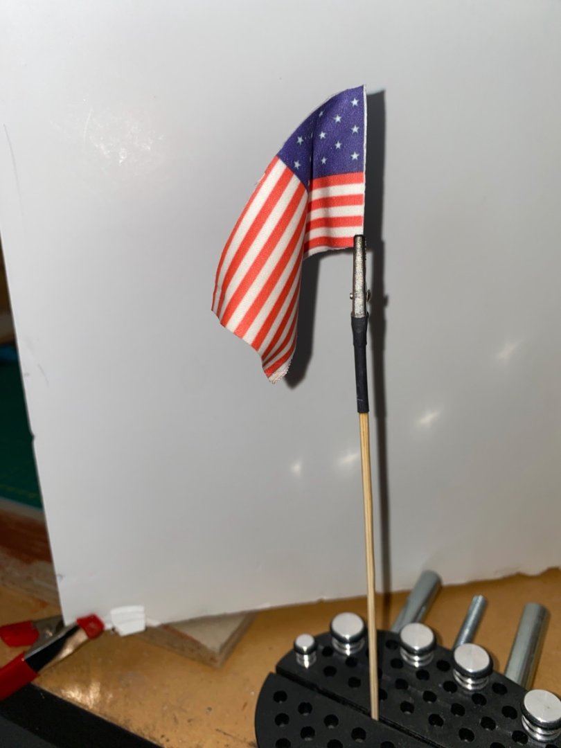
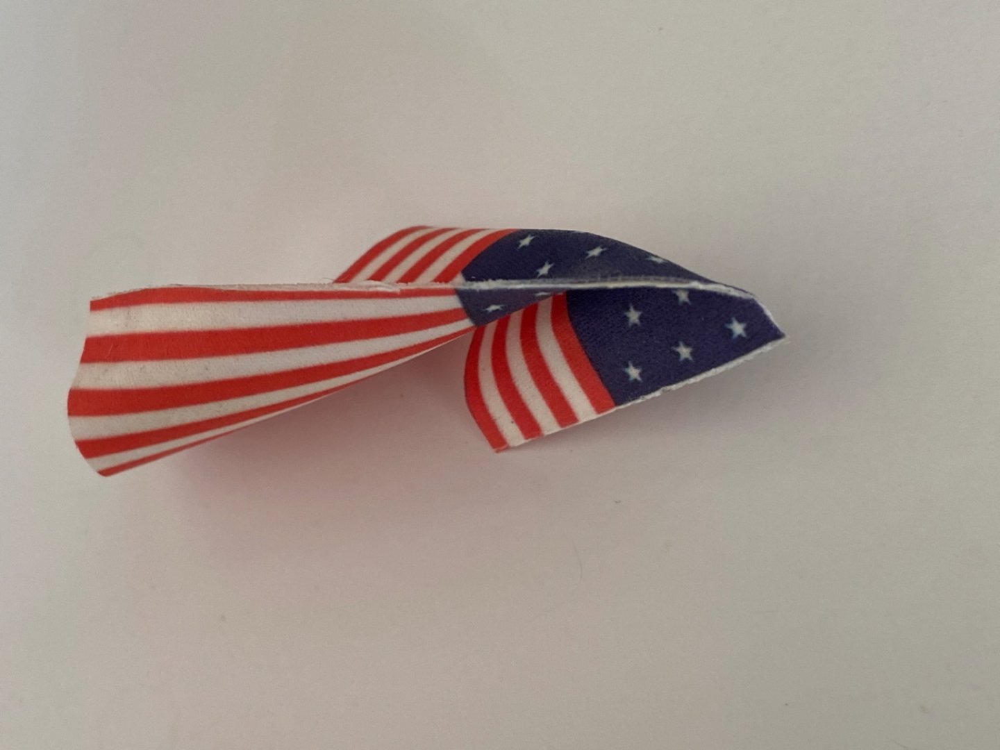
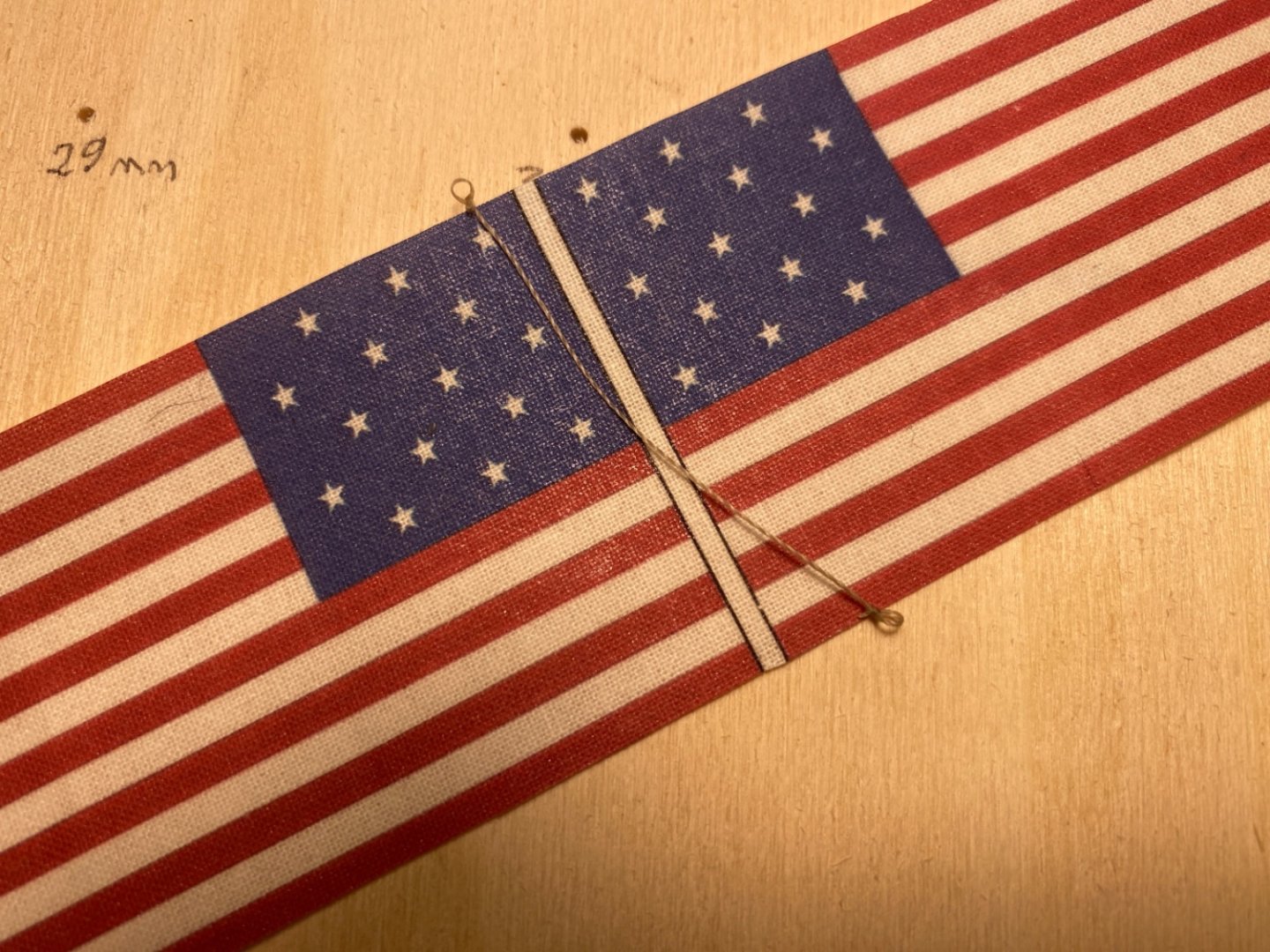
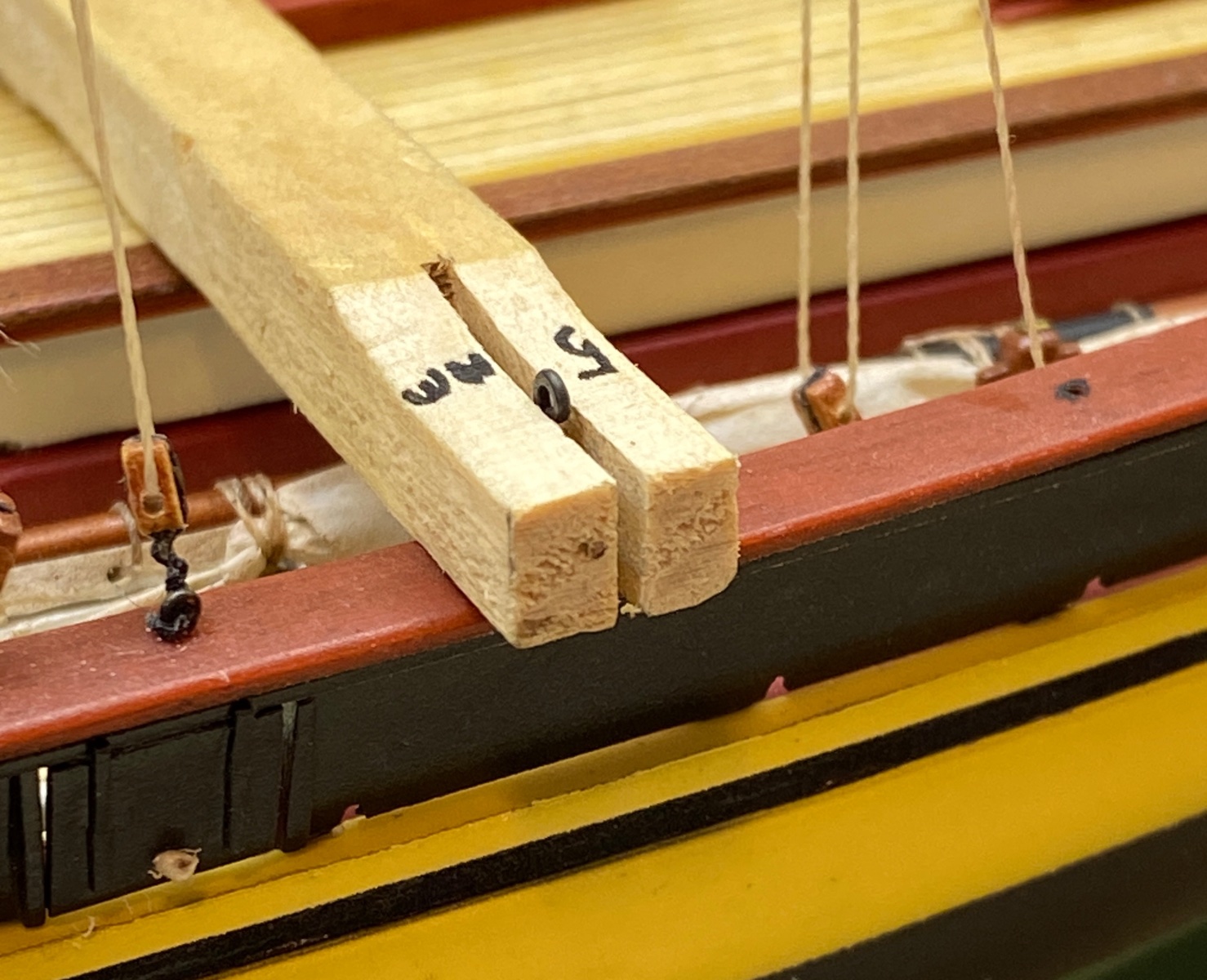
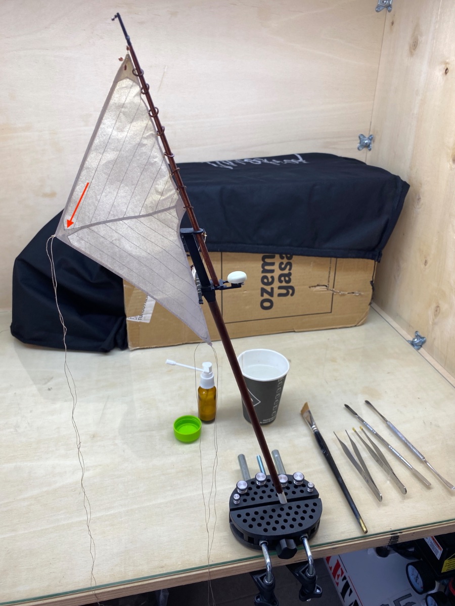
At the stage of final preparation of the flags I made an experiment with a sample which was not skewed!
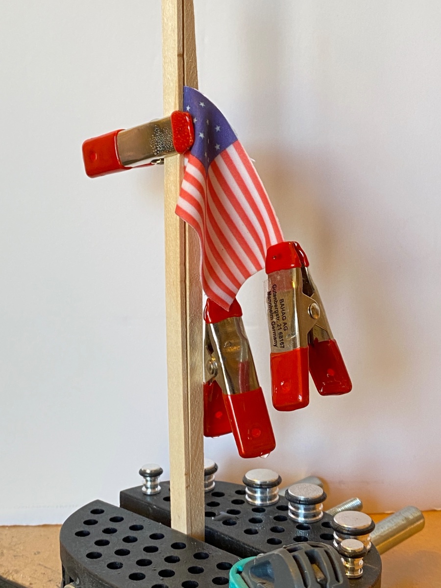
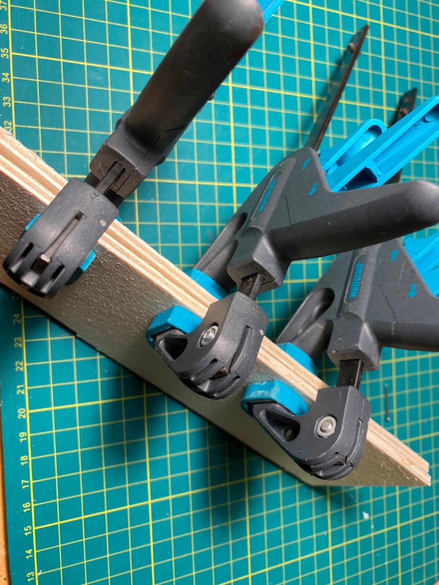
The US flag was folded and glued by textile glue. Then it was clamped between two wood strips which was clamped in a vise. The flag was wetted by water and a metal clamps were used on two points. Water diluted white glue was applied. After the flag was dry it was removed from the jig. The result satisfied me.


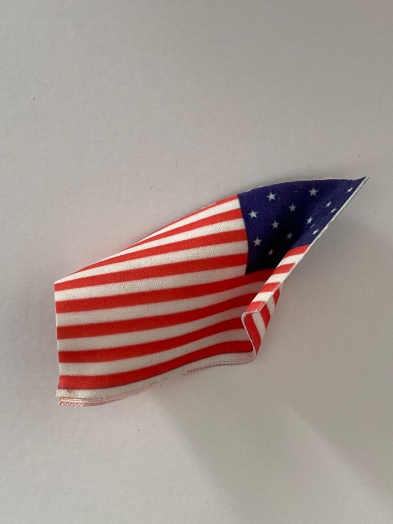
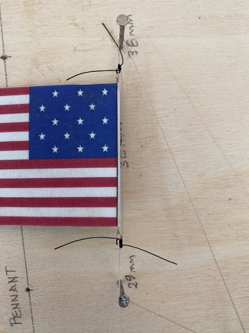
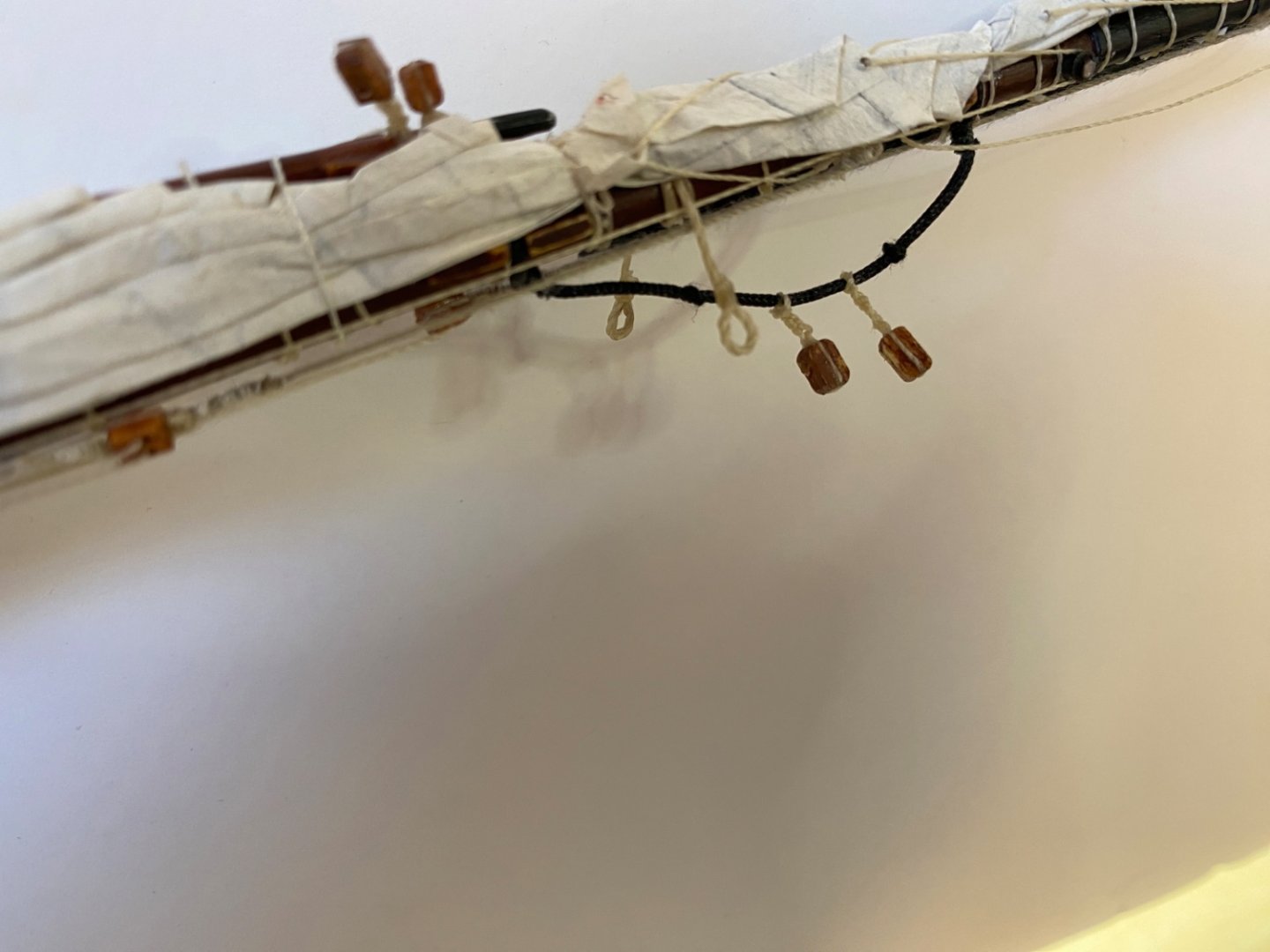
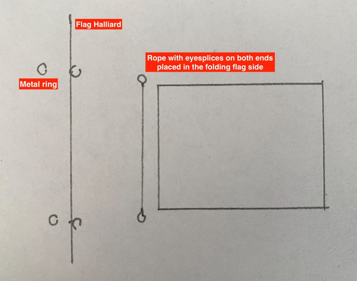
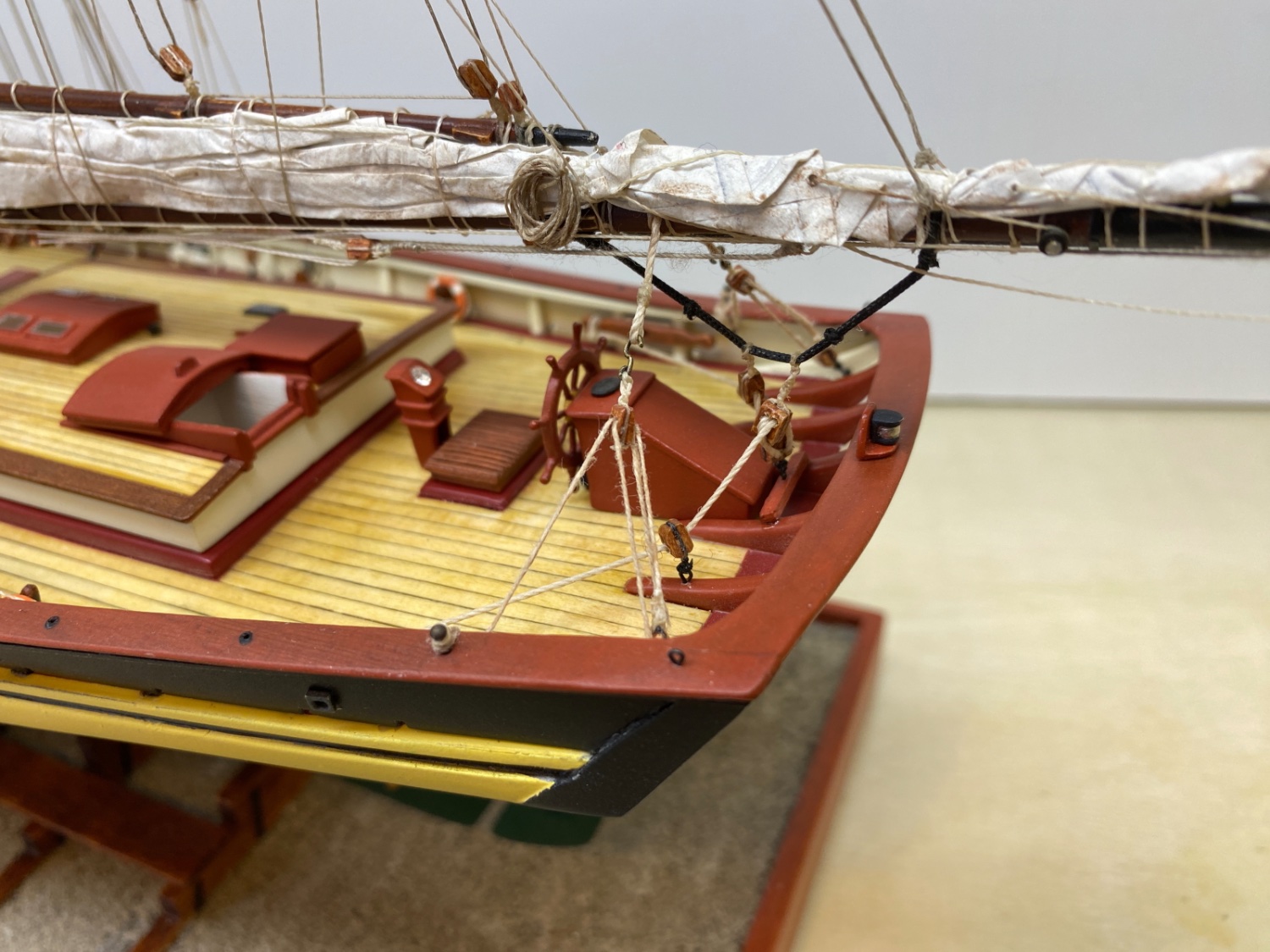
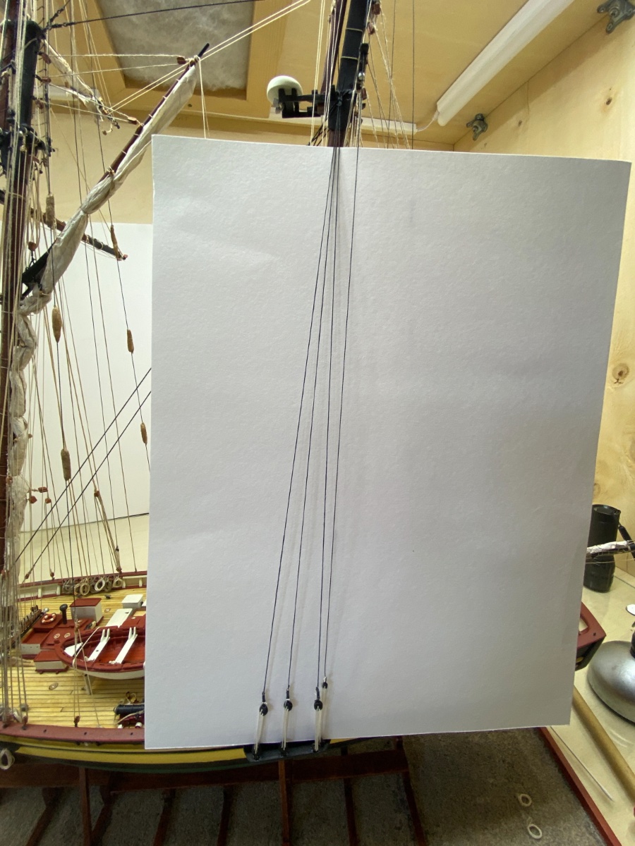
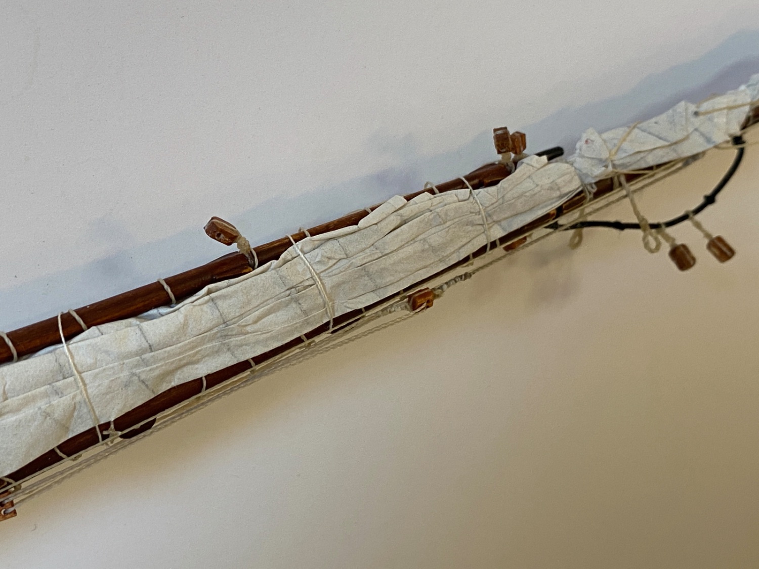
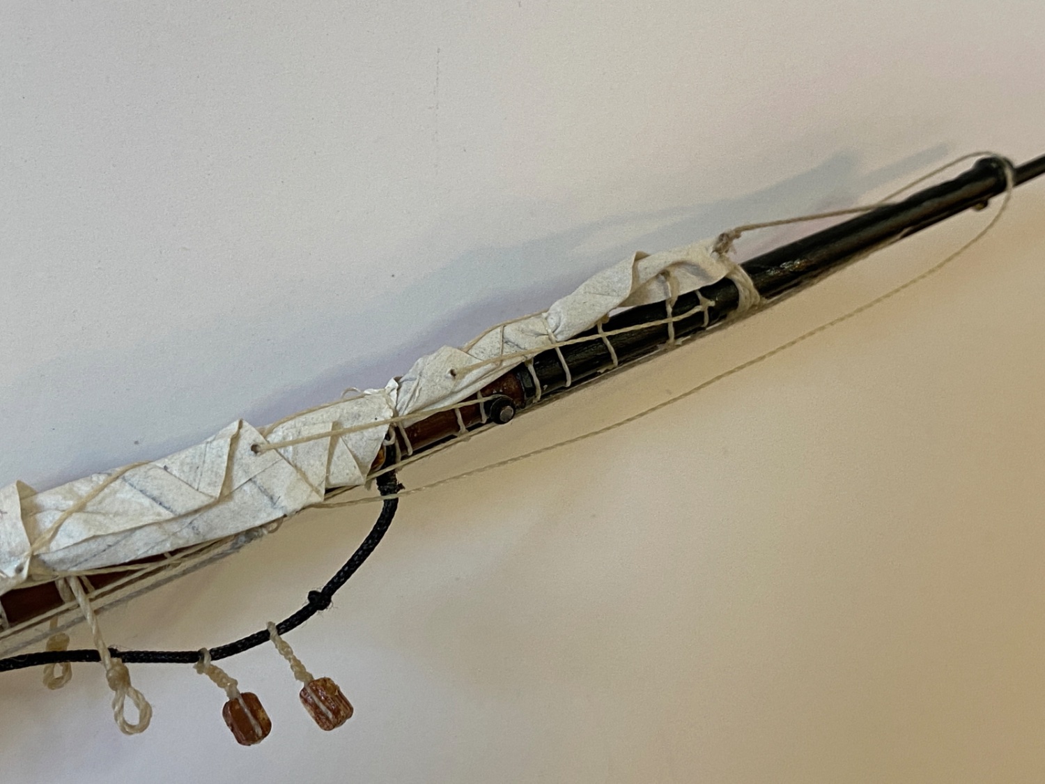
However the size of the skewed flags were somewhat smaller and I decided to use the straight samples. In order to simulate the flag grommets and halliard snap hooks and thus make the flags interchangeable in future, I decided to make the arrangement seen in the photo below.

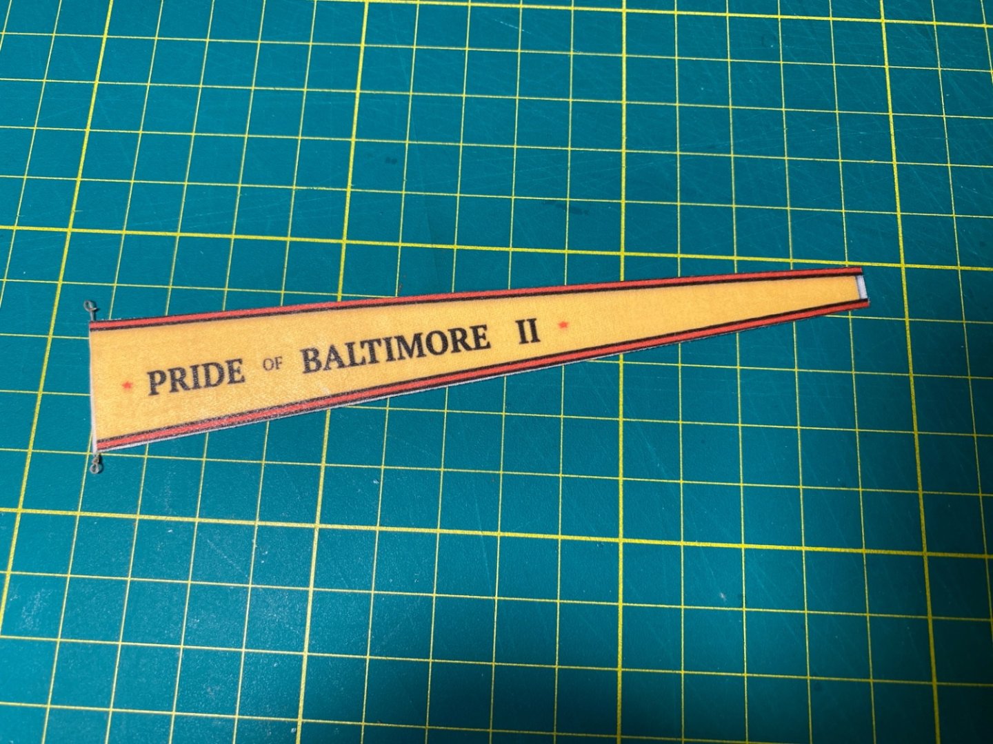
The flags and pendant were cut by using a sharp knife and steel ruler. The excess cloth was left at the flag ends. The pendant used was the one with red arrow.

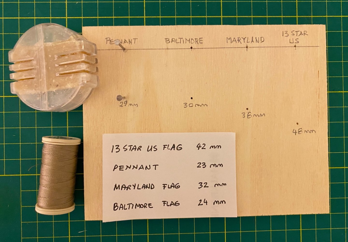
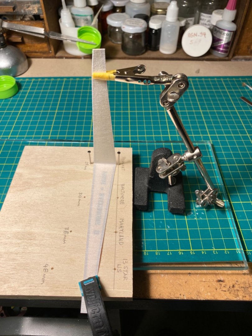
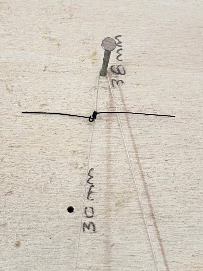
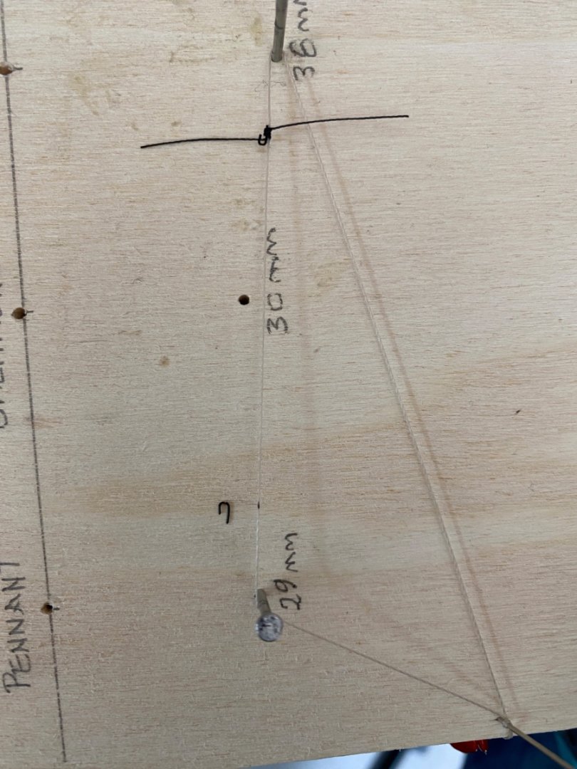
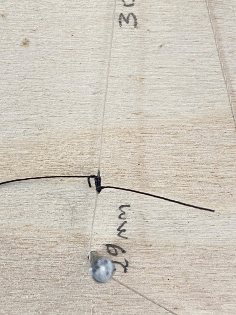
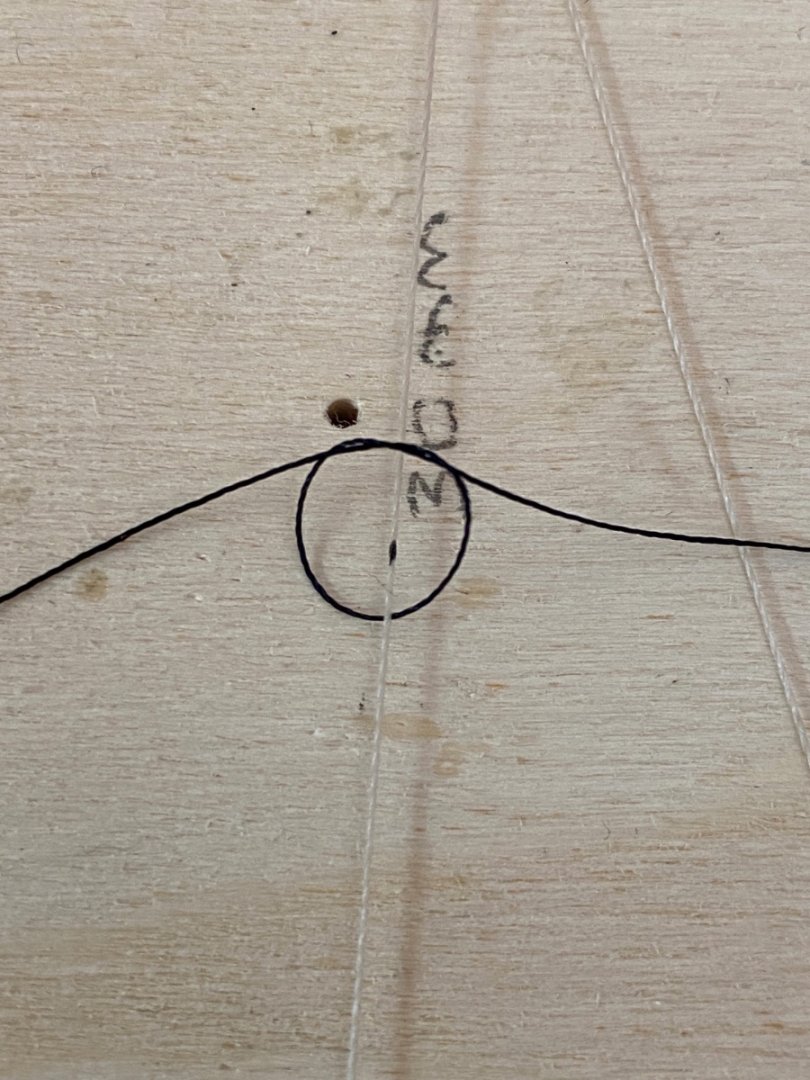
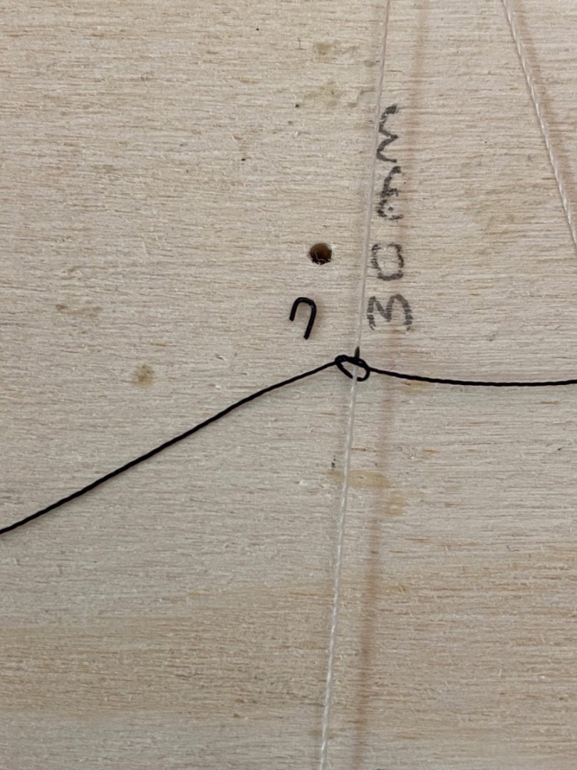
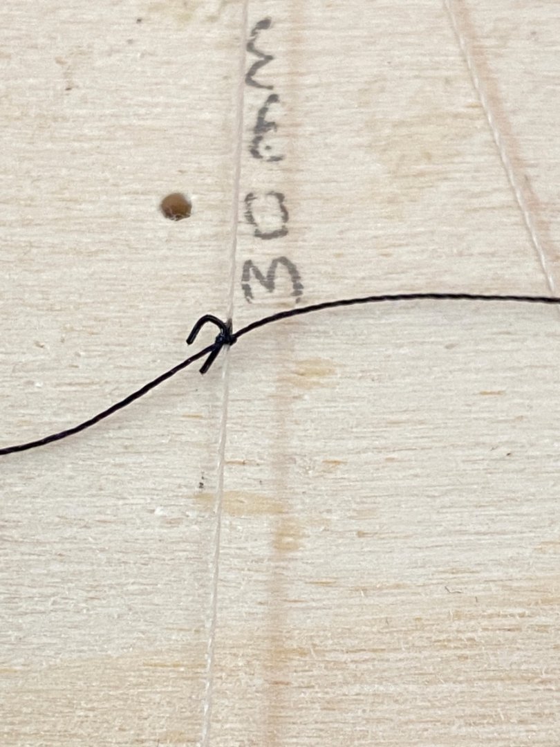
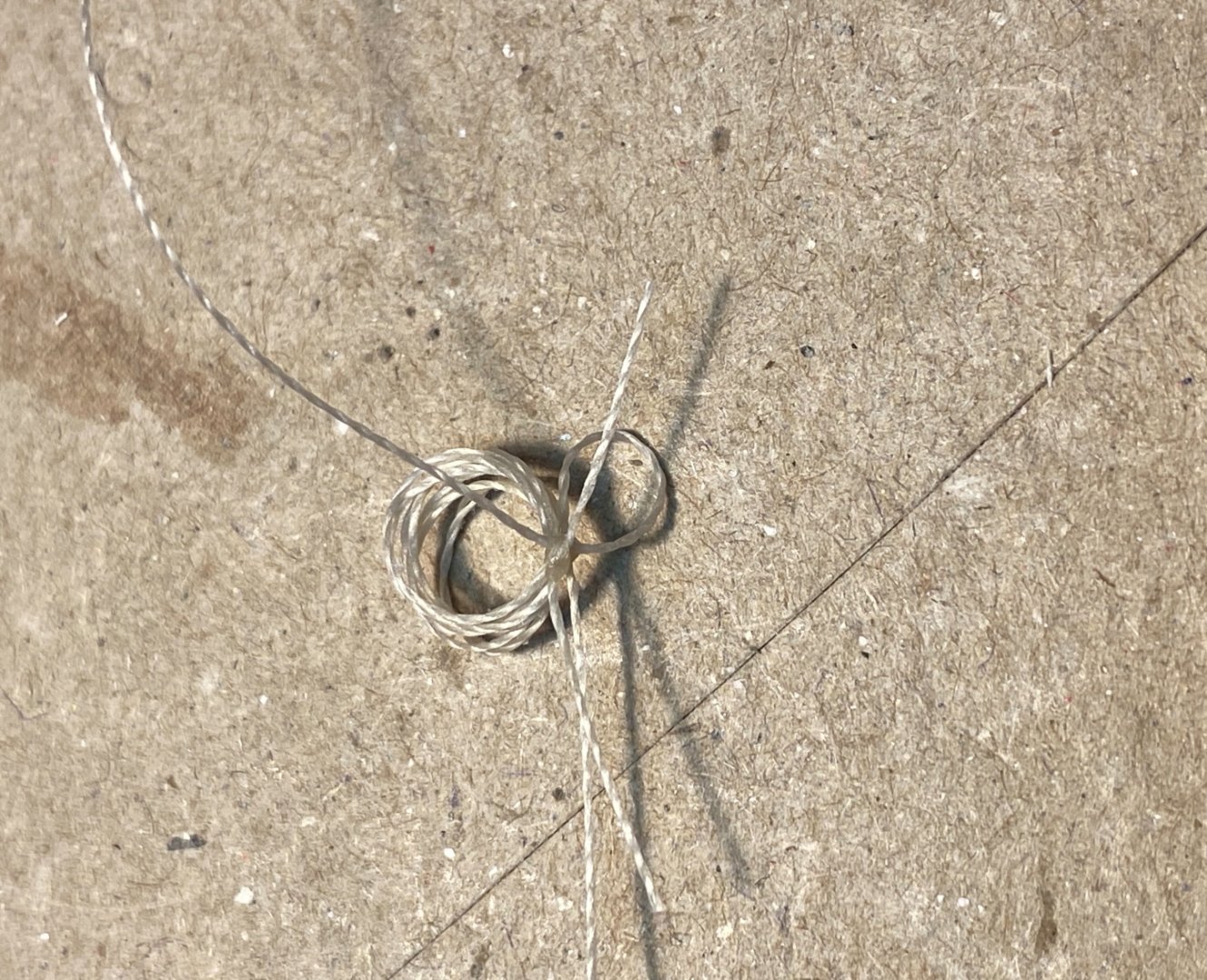
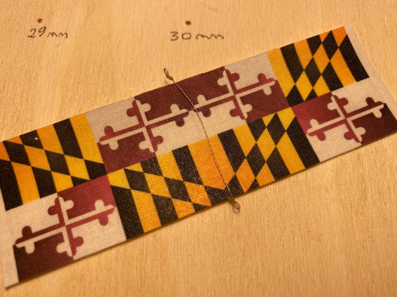
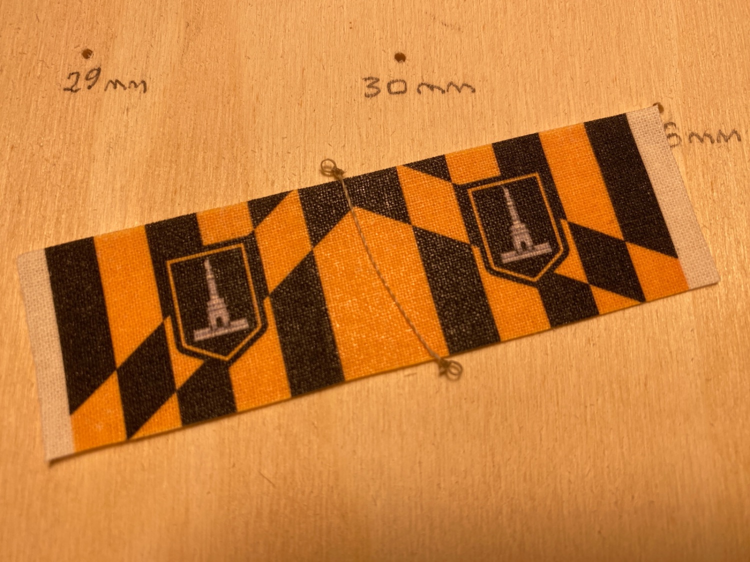
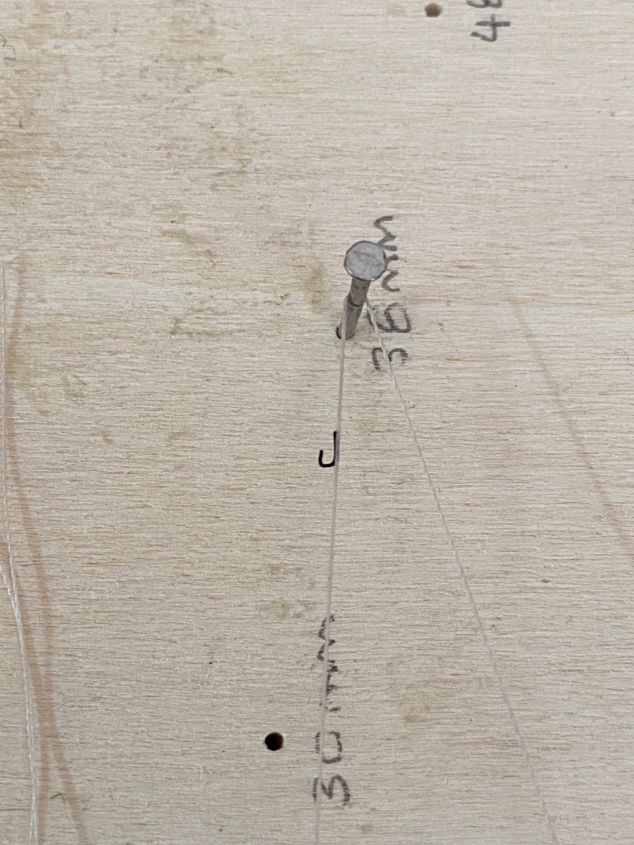
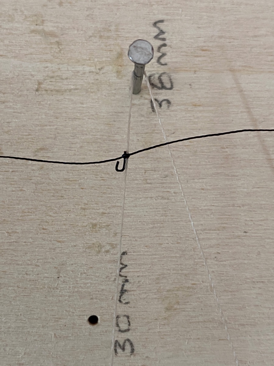
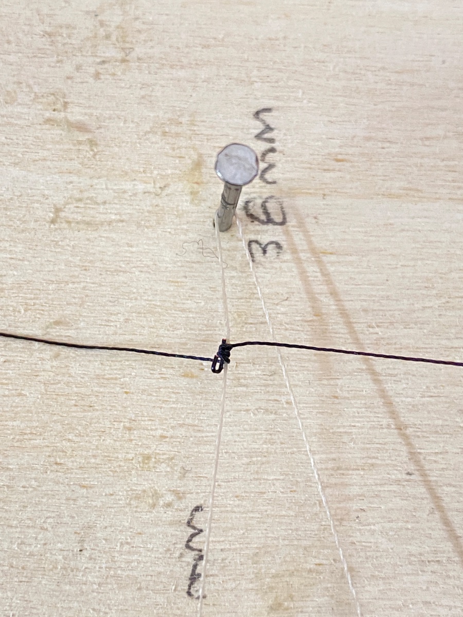
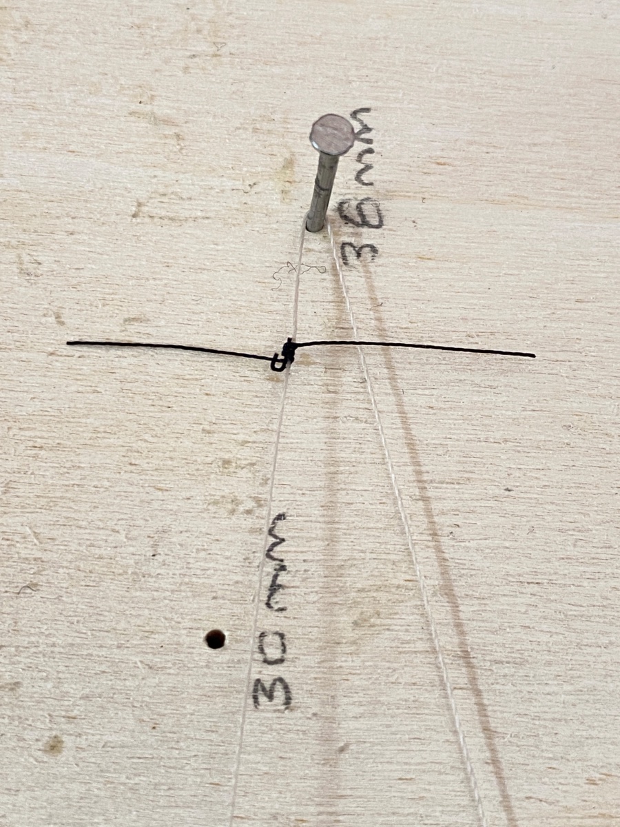
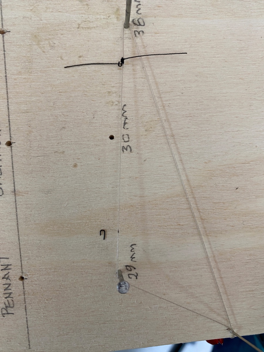
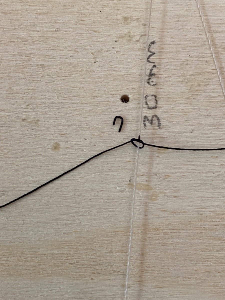
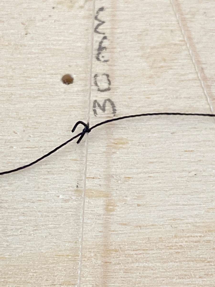
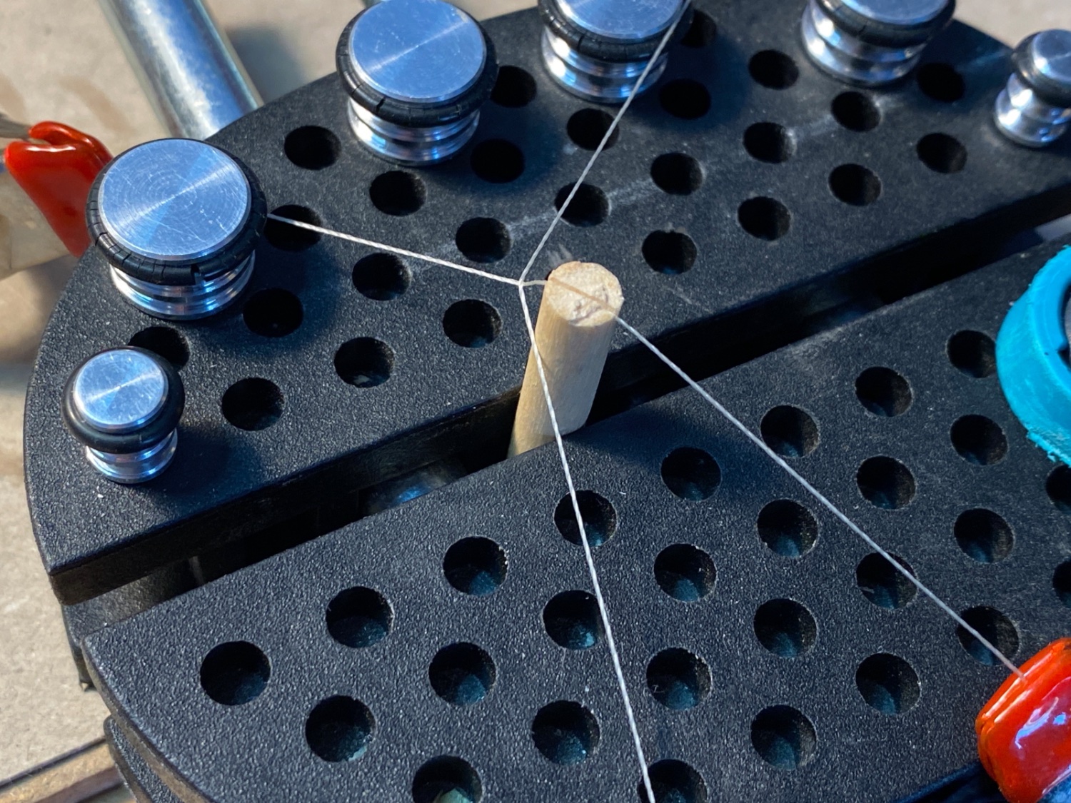
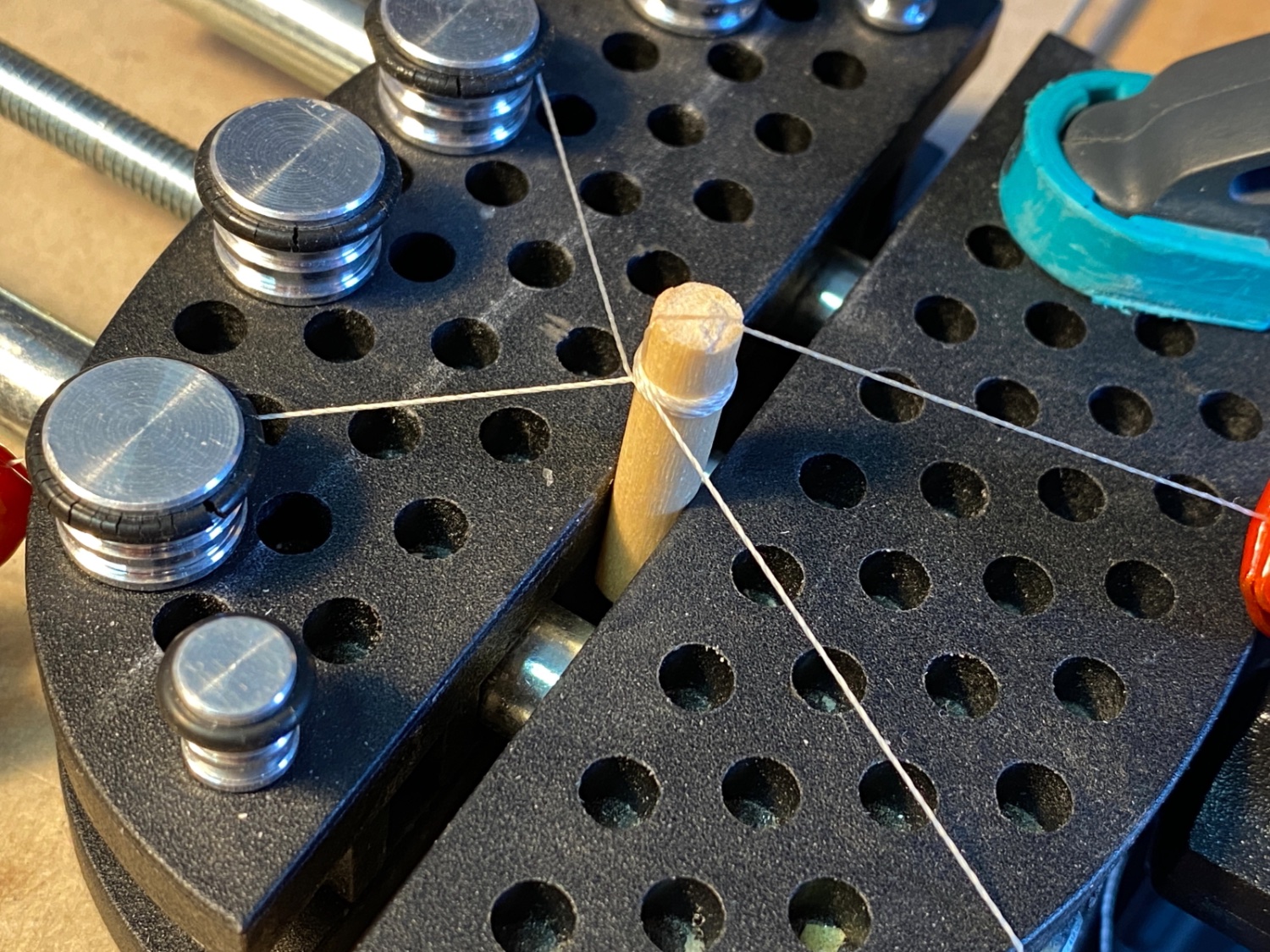
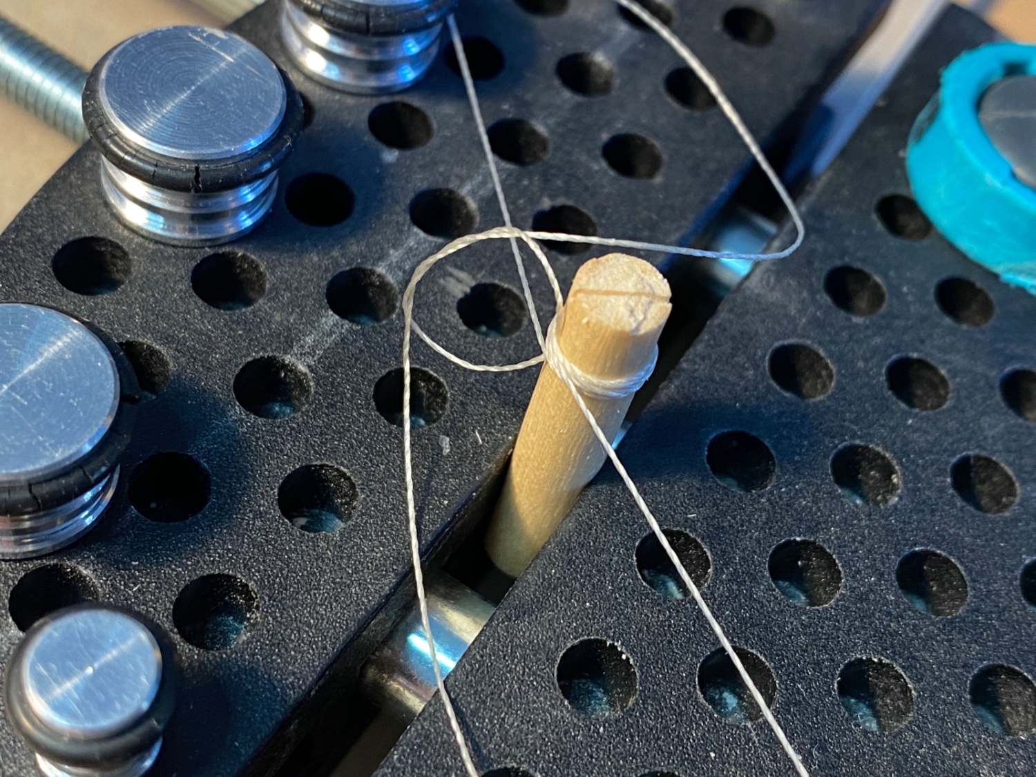
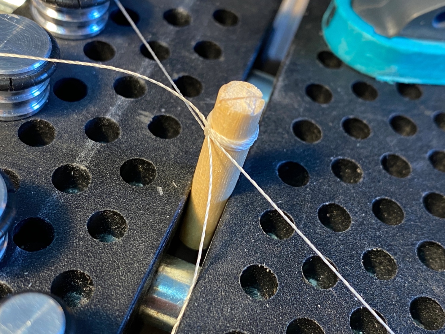
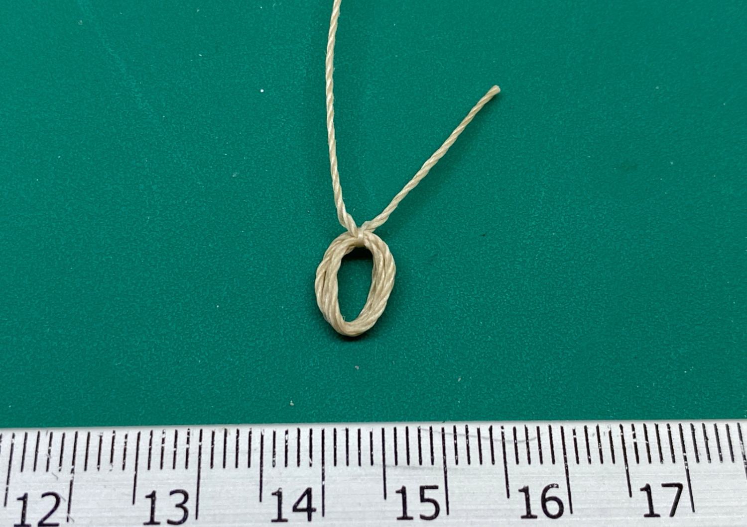
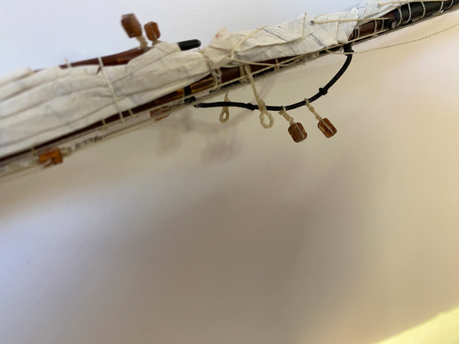
On order to make the ropes with looped ends to simulate grommets, a jig was made with separate distance positions for the flags and pendant. Thread was bees waxed.
Ropes with looped ends were made for all flags and pendant

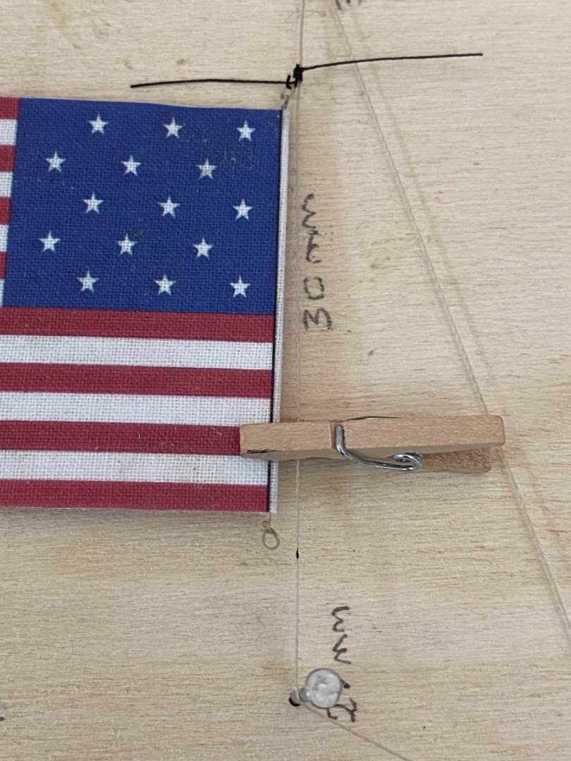
All the flags and the pendant were ready to be folded with the ropes with looped ends ready too.

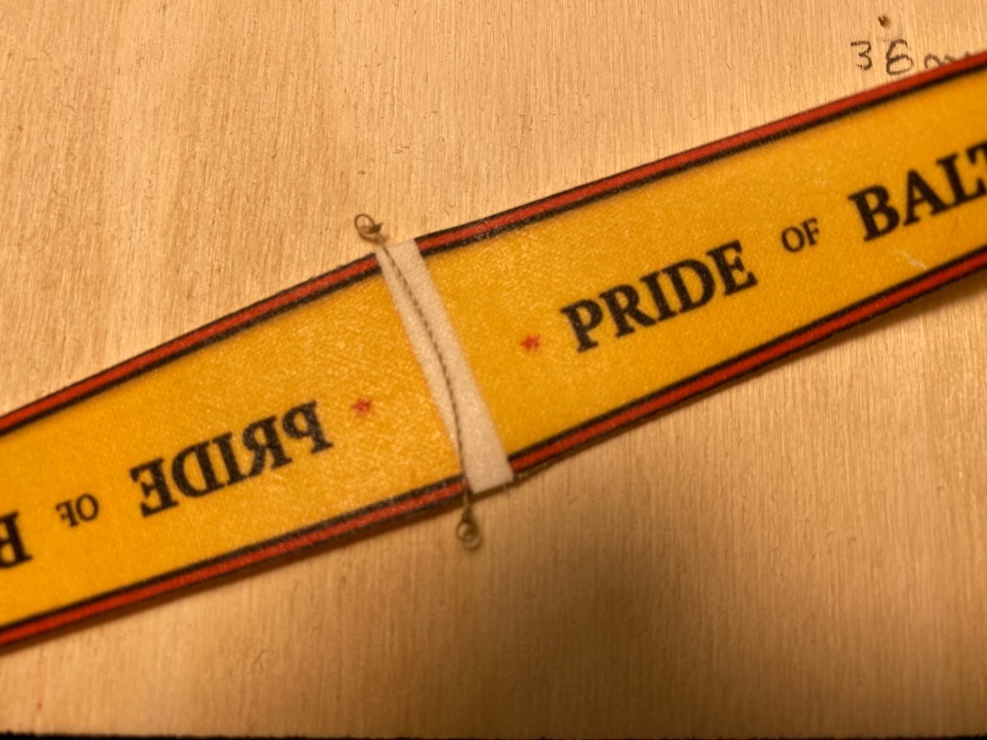
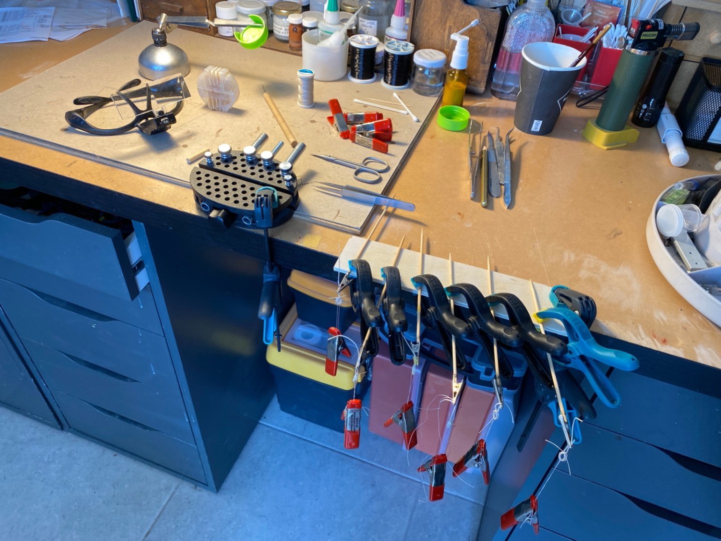
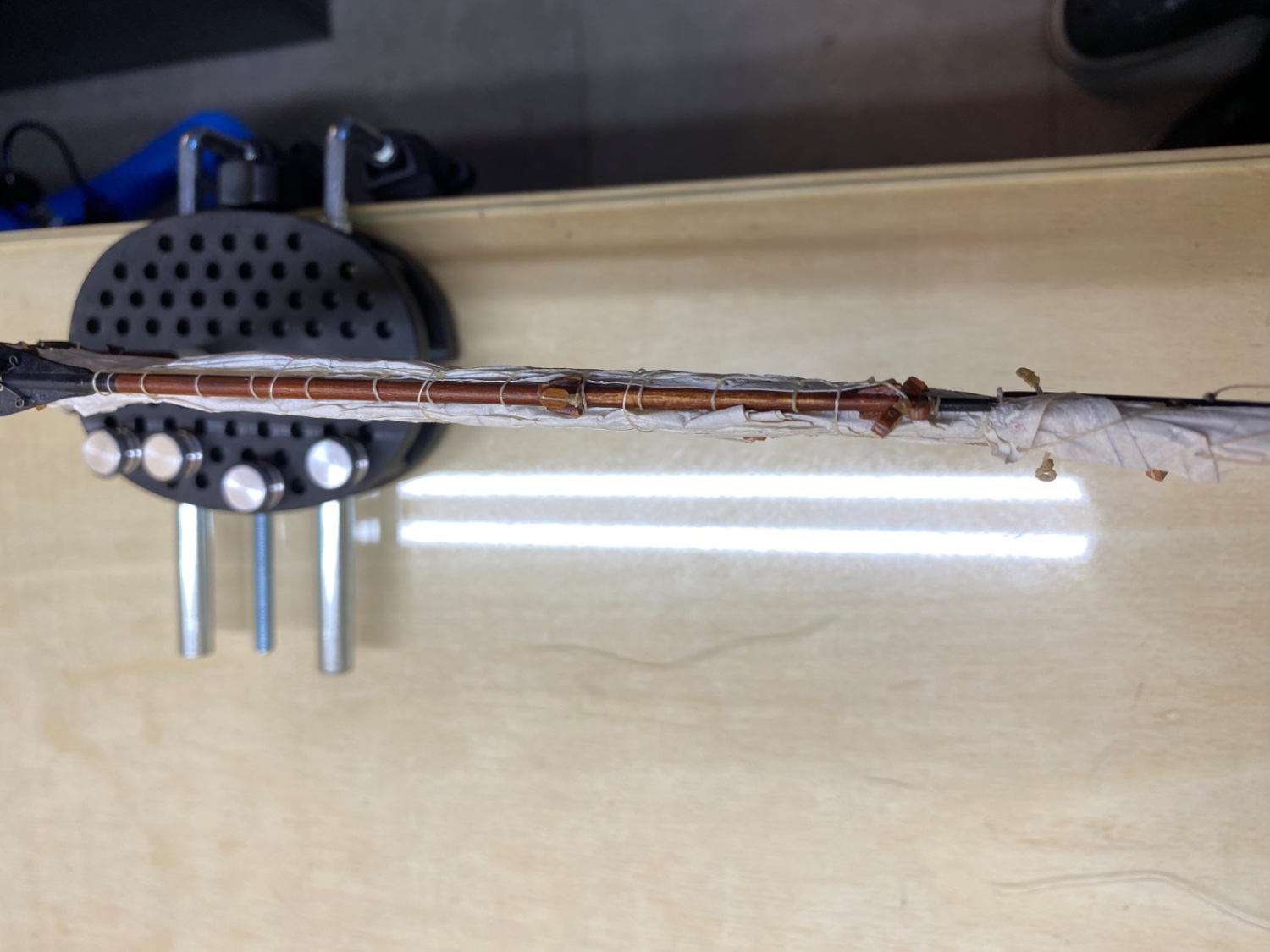
This was the method. The rope was glued first. Then the pendant was glued folded over. It was clamped between two wood pieces to dry.


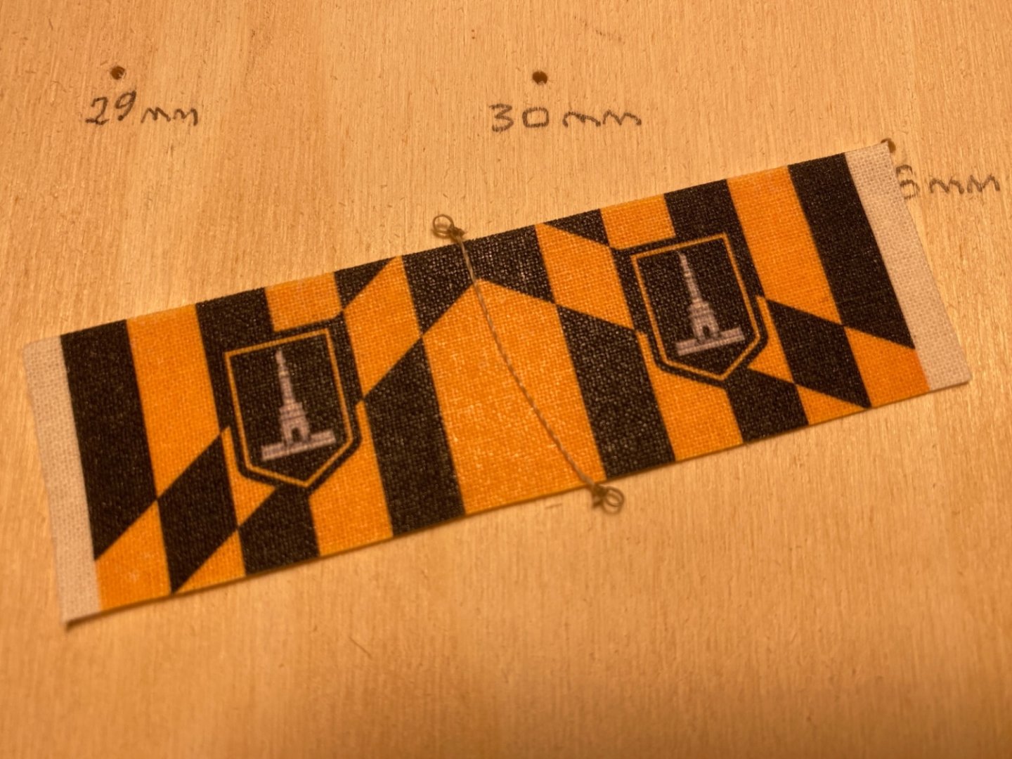
All the flags were ready with their loop ended ropes. The flag fronts were cut to size
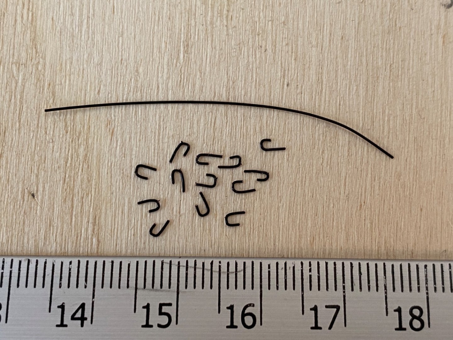
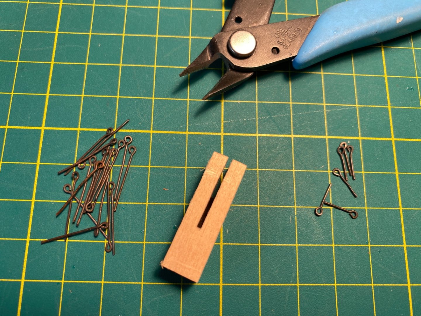
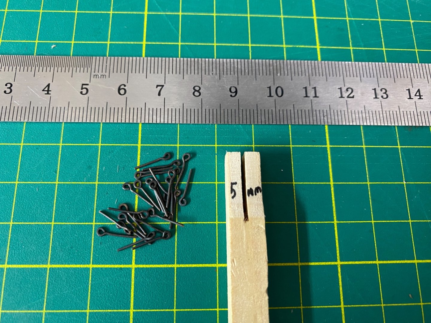
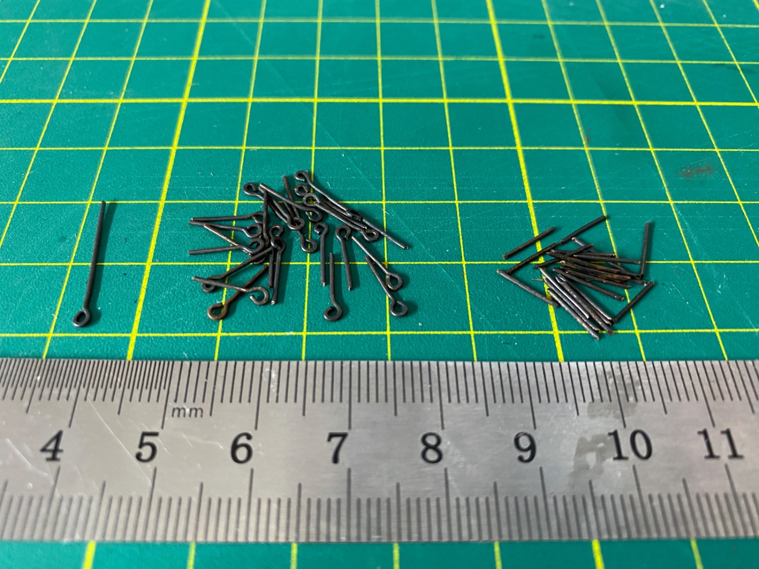
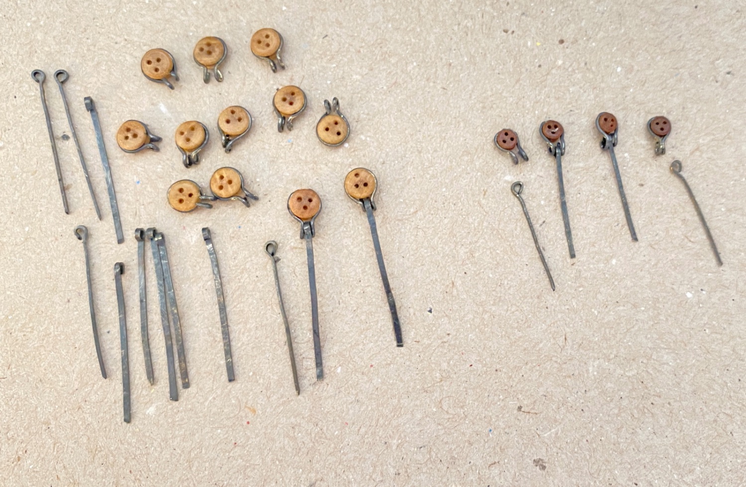
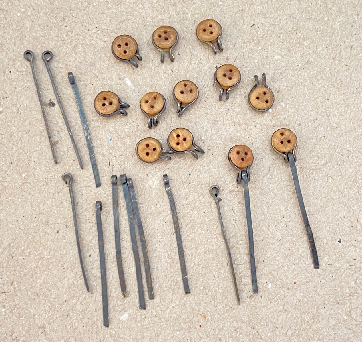
The next step was to prepare the halliards for each flag and the metal rings to simulate snap hooks.
I decided to make rectangle shape rather than circular ring shape.
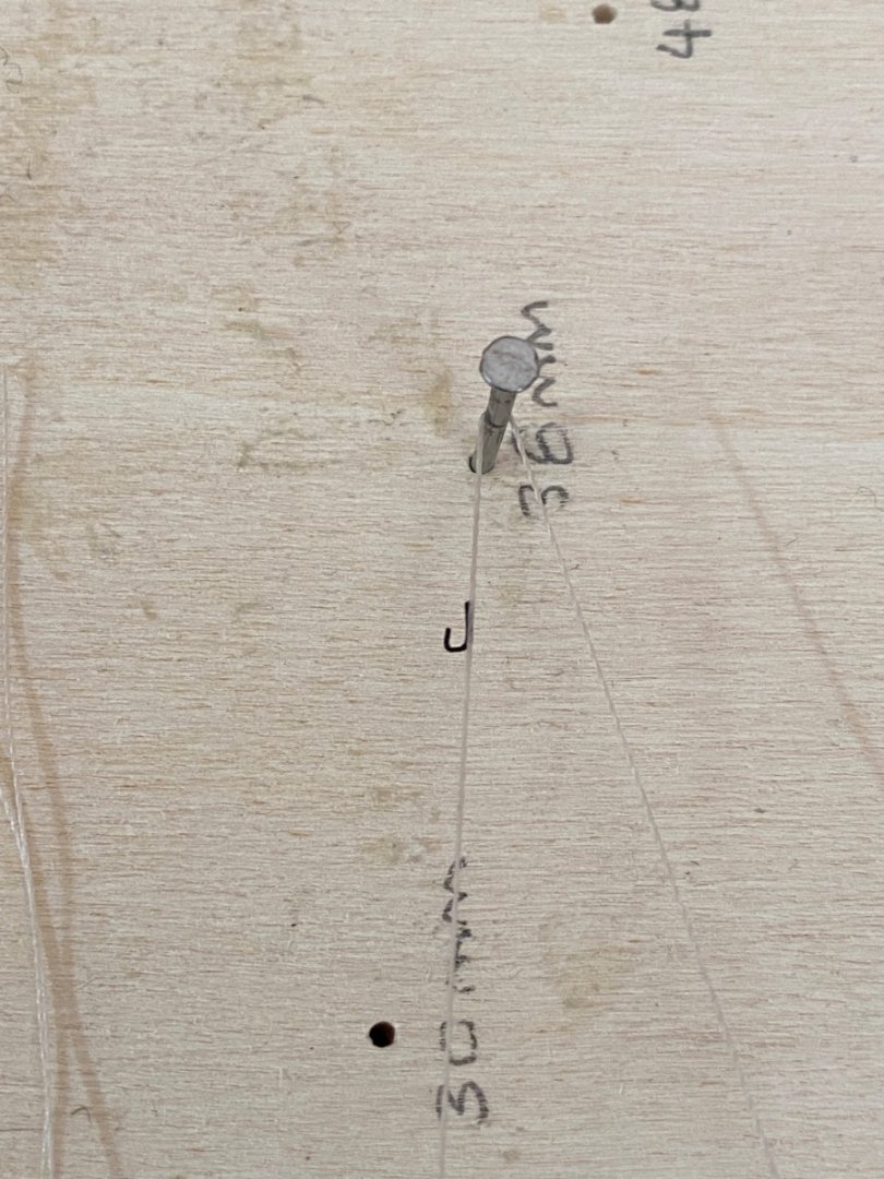
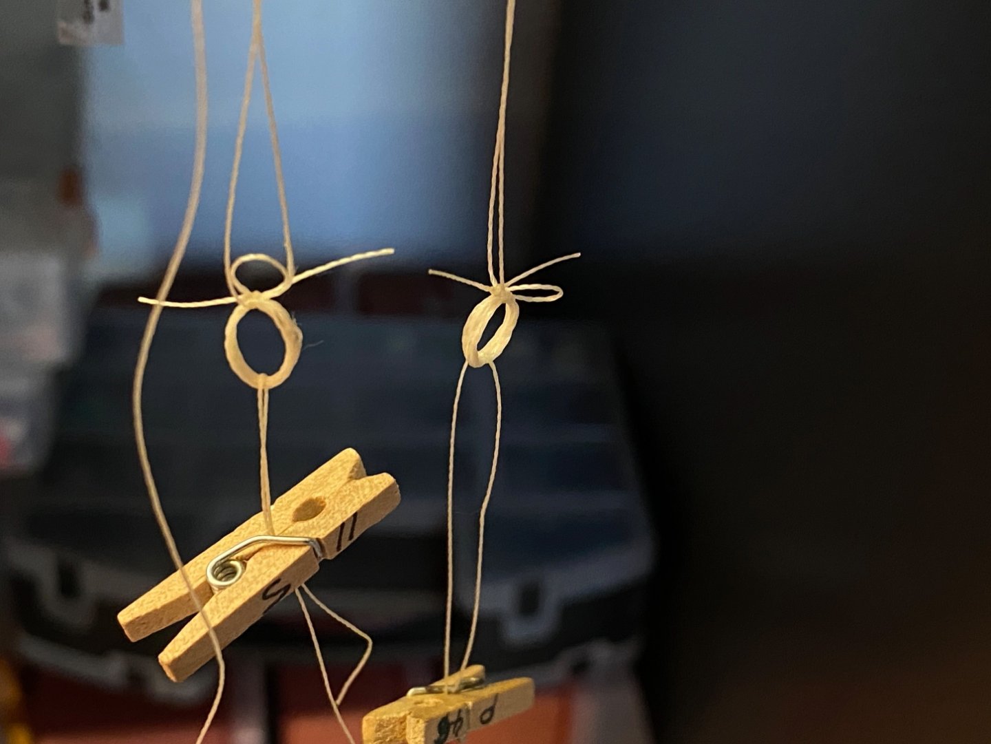
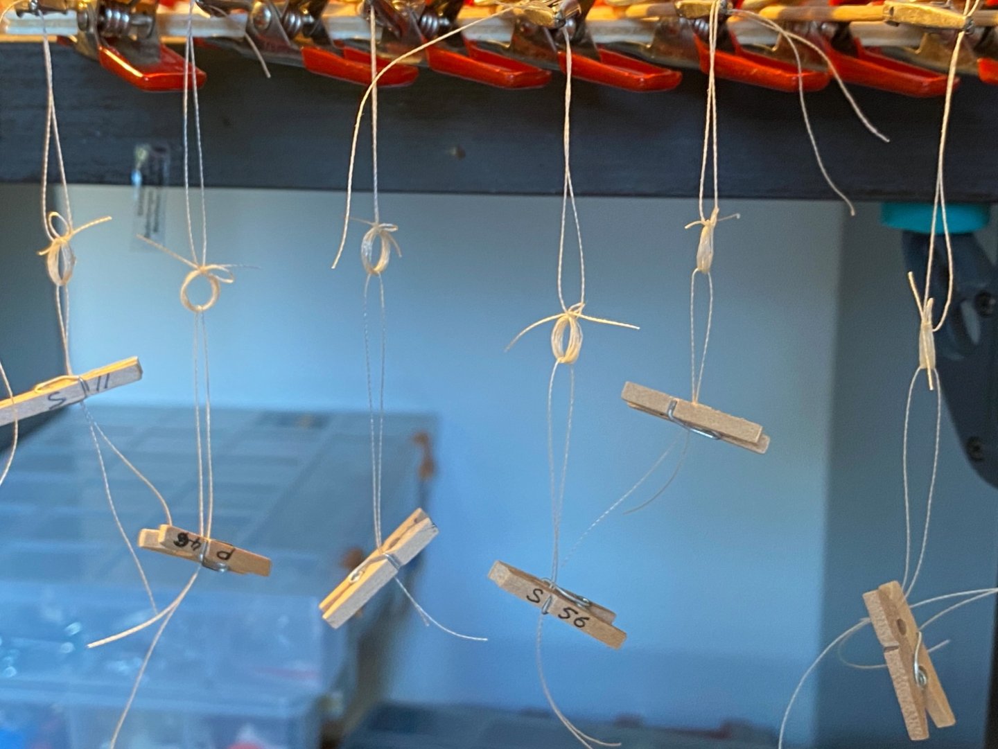
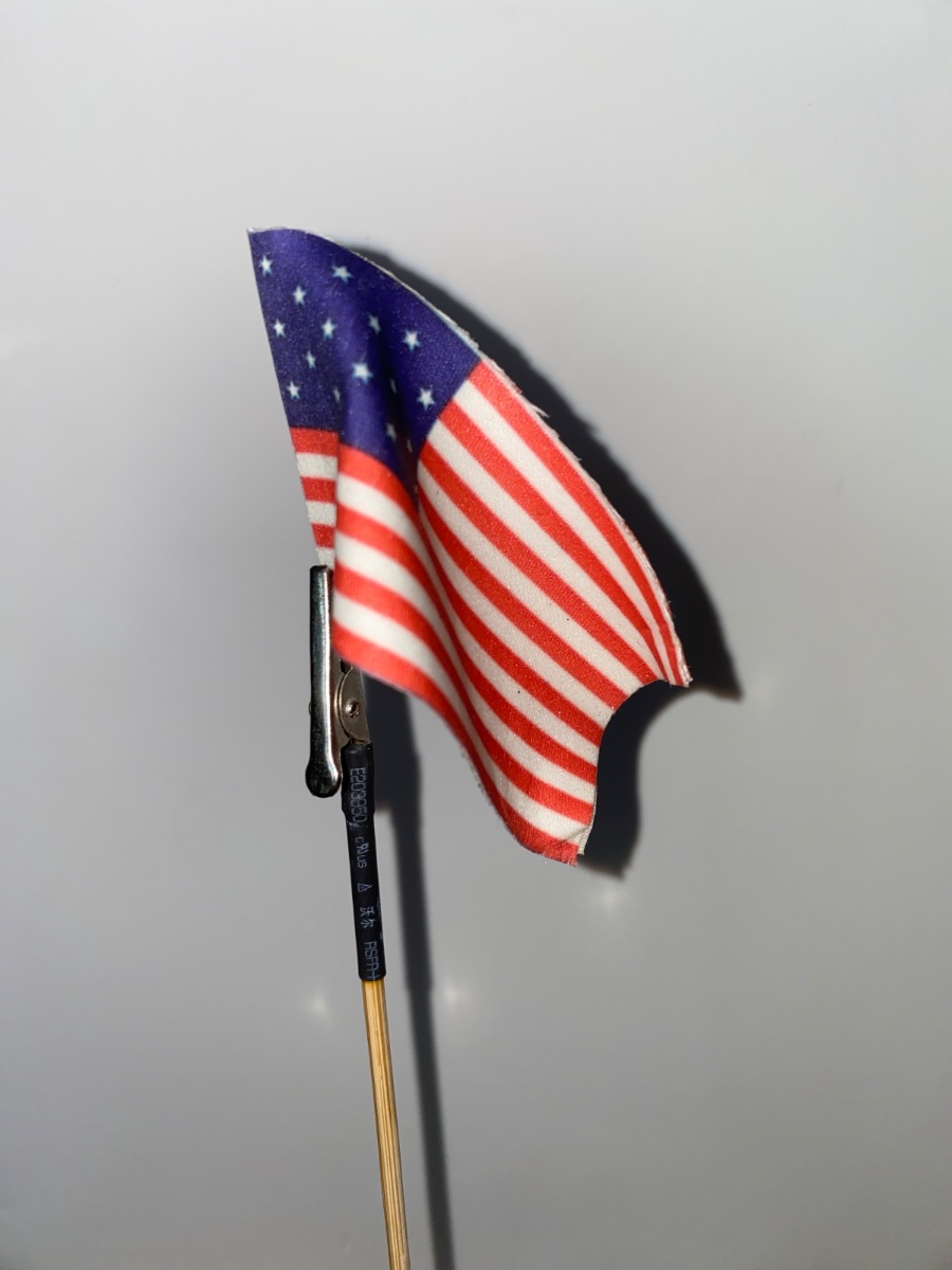
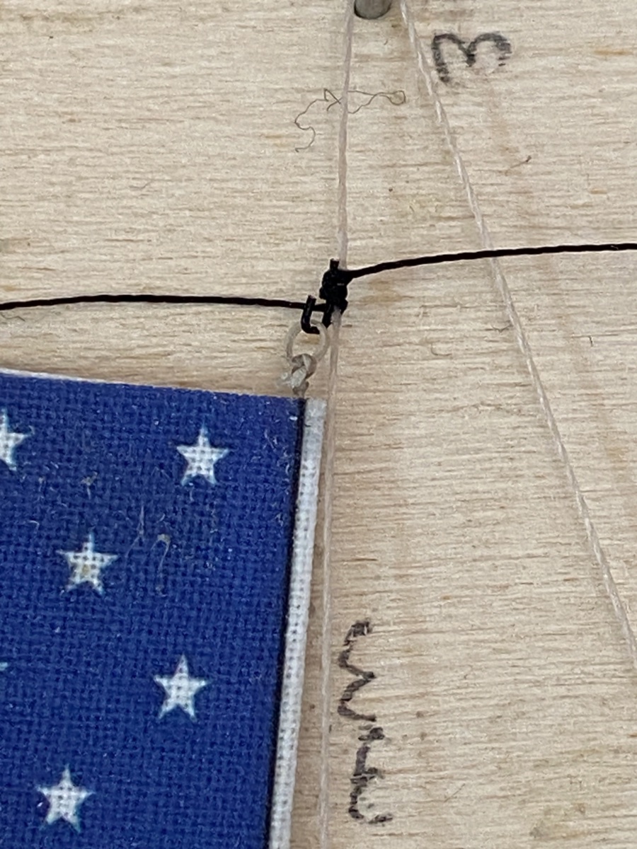
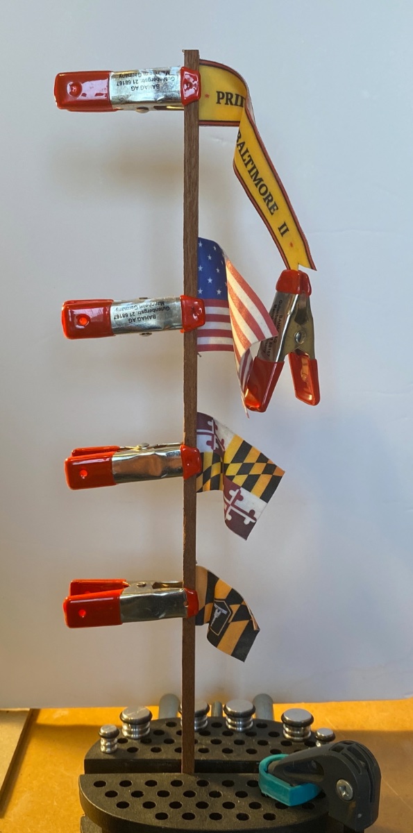
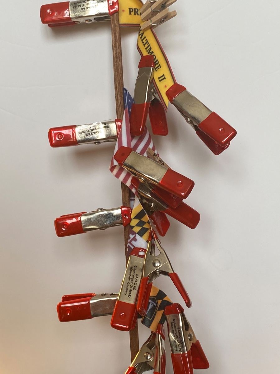
Another jig was made and the halliard line was fixed leaving a part of it where the flag is to be seized. First the upper metal clip was glued and later seized to halliard line.
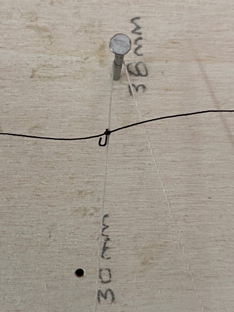
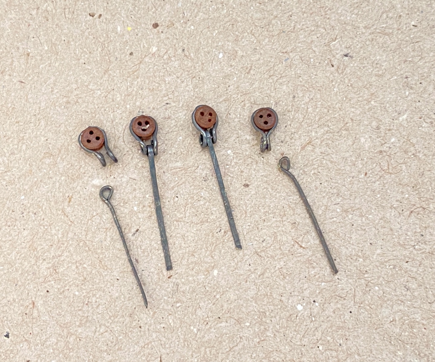
The flags upper loop is hooked to the metal clip and the position of the lower loop was marked on the halliard line. The lower clip was then seized to halliard line at this mark.

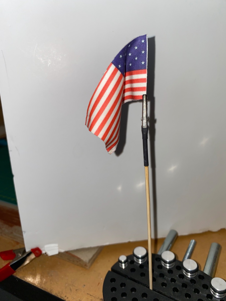
Flag is then hooked to the upper and lower clips. The excess rope of the clips cut.

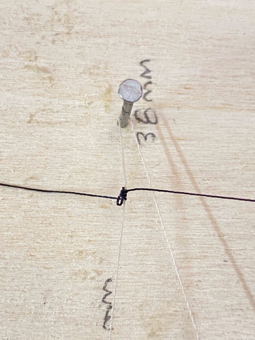
An alternate way to seize the metal clips to halliard line. First place the loose knot at the mark. Then insert the metal clip later.
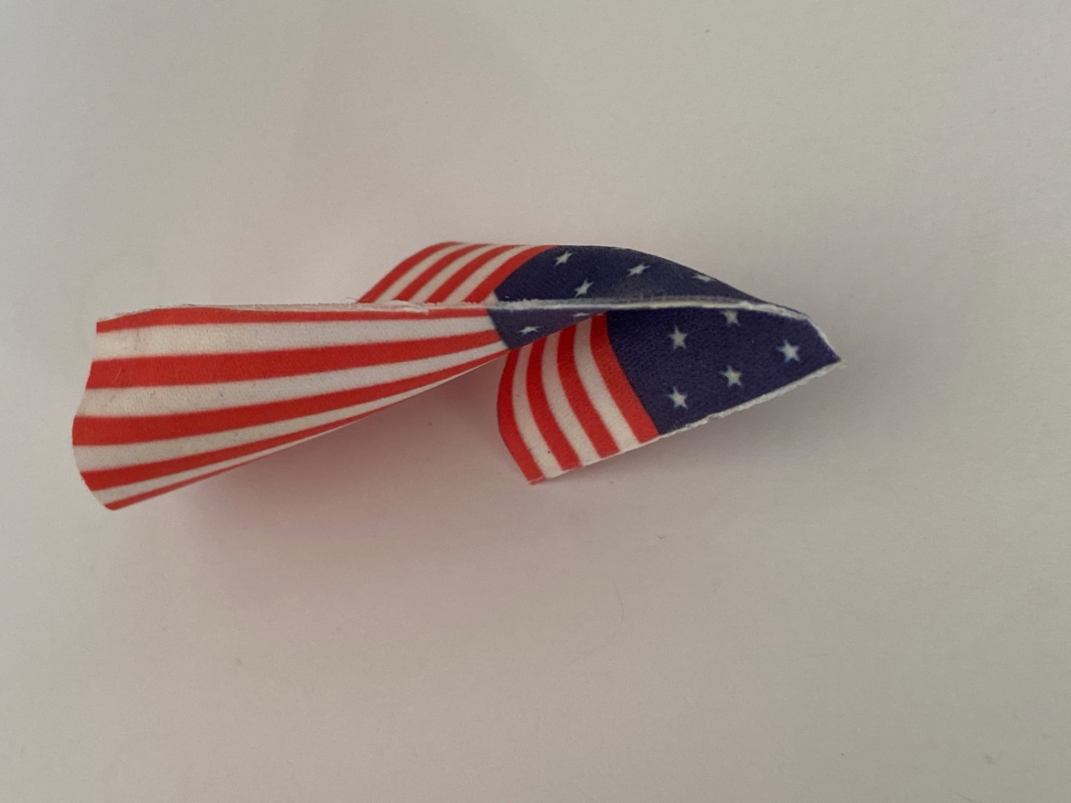
After all the metal clips were seized to their halliards it was time to give the flags and pendant their final shape. I used the same technique I described at the beginning of the post.


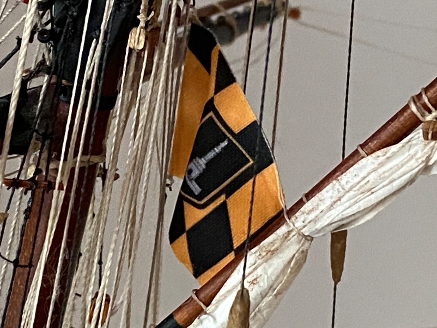
The Baltimore flag was put to dry in upside down position . It was treated again. As all the flags were shaped and their halliards with metal clips seized were ready, the final step was to install them on the model.
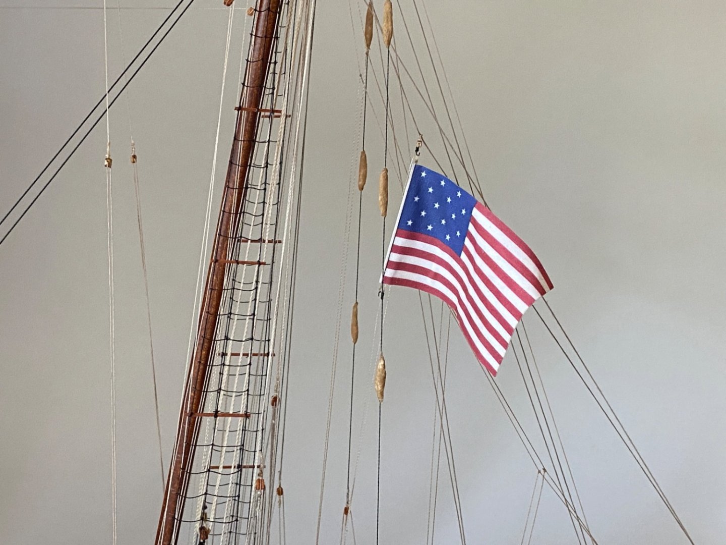
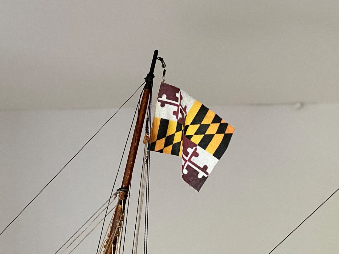

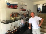
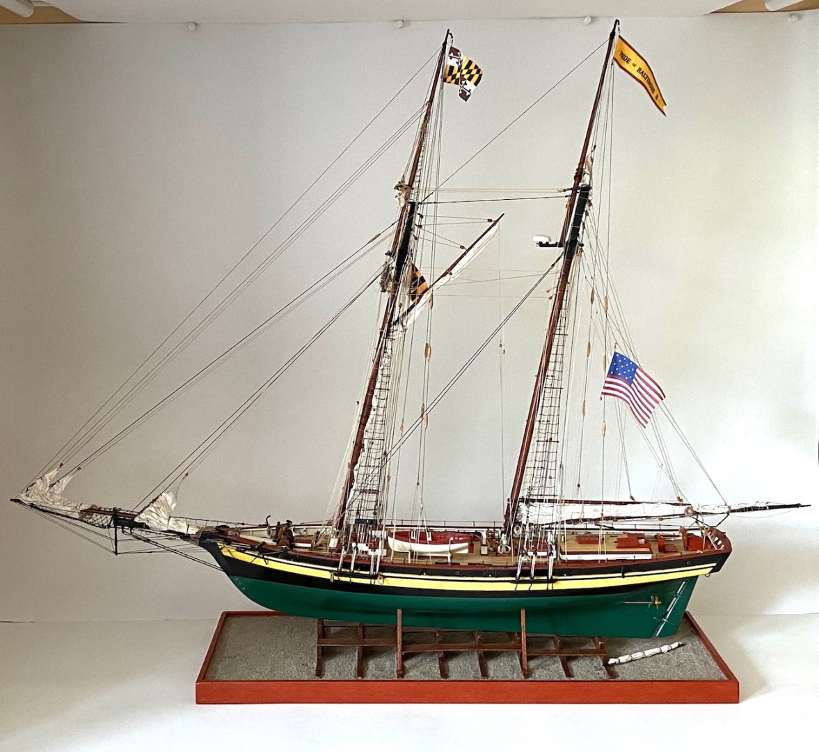
By the installation of the Baltimore Flag , 27 month build journey was finished. Here is the first photo I took right after the last flag was installed.
- Shotlocker, ccoyle, Prowler901 and 1 other
-
 3
3
-
 1
1
-
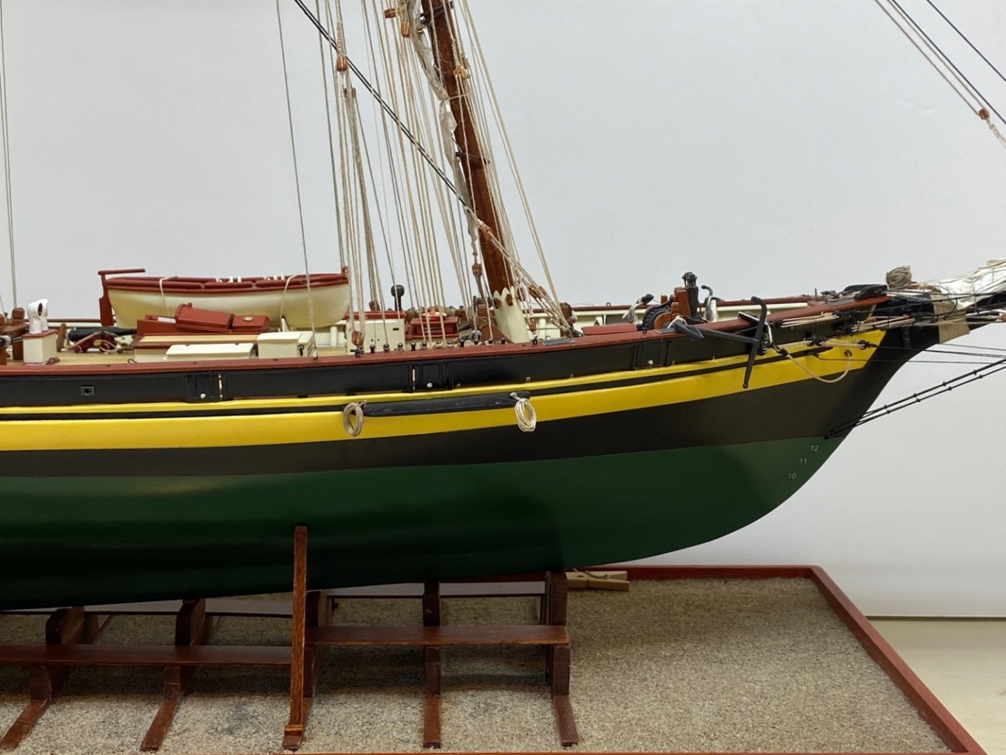
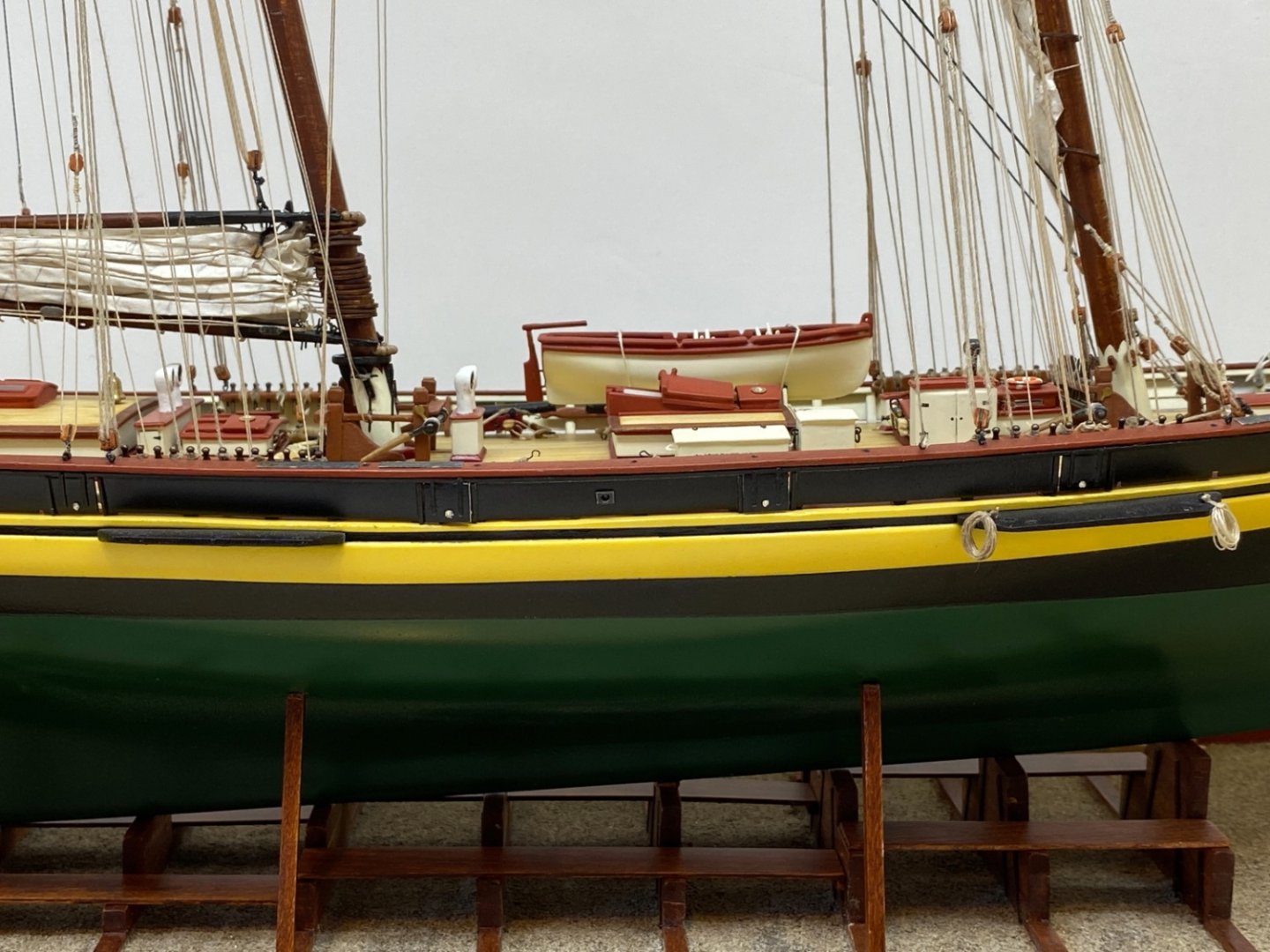
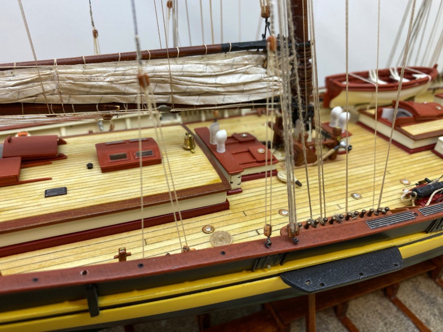
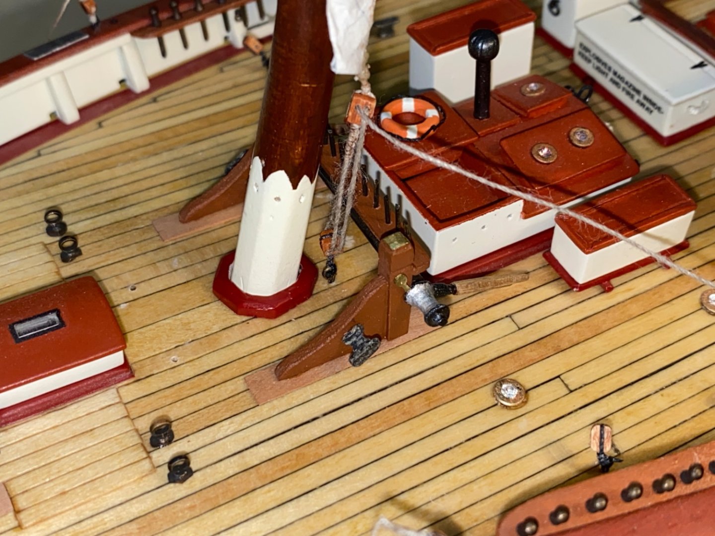
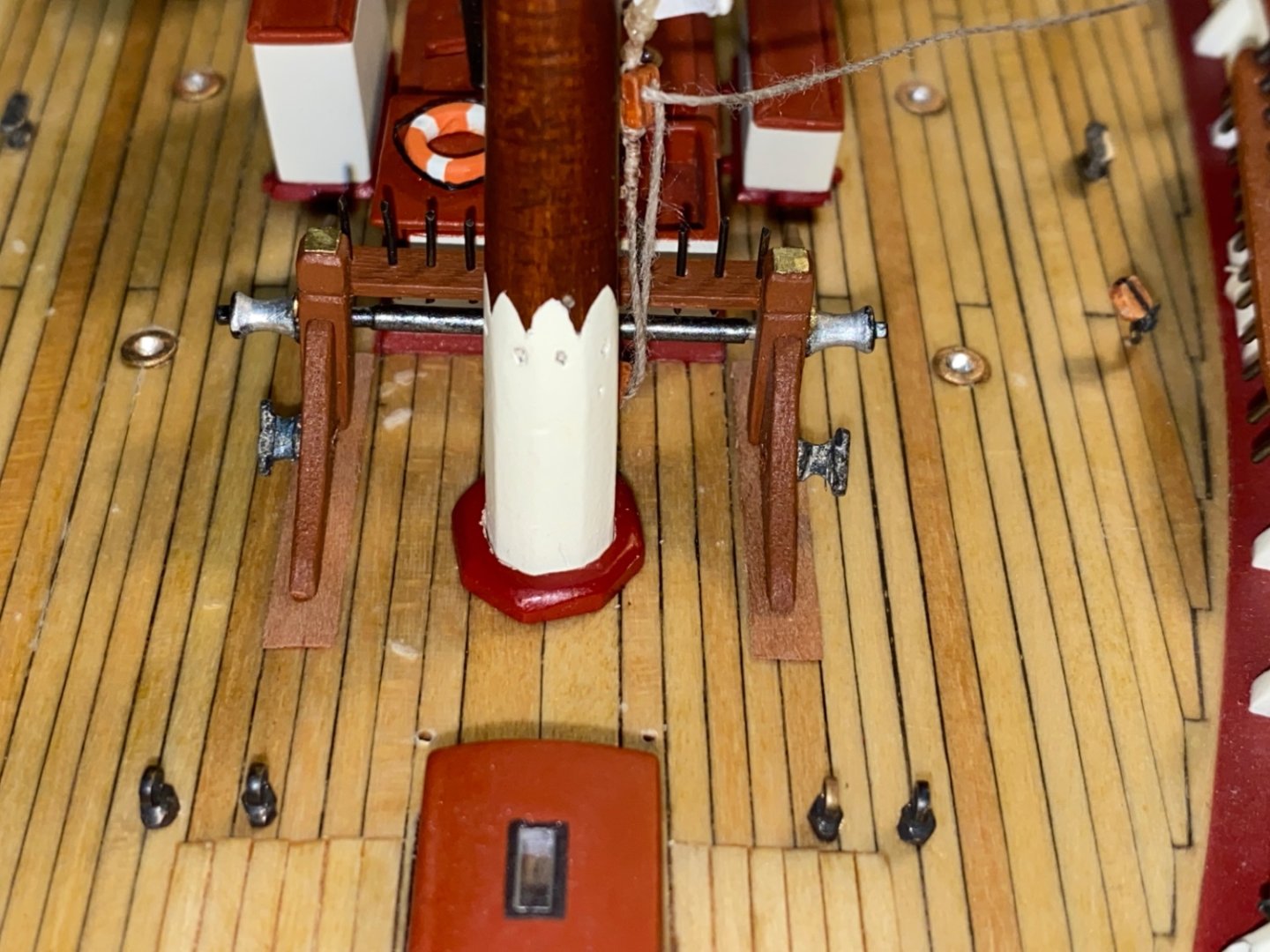
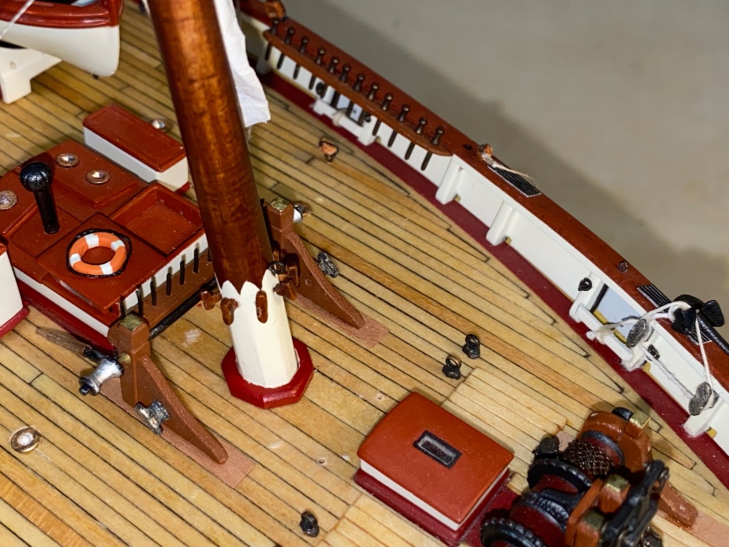
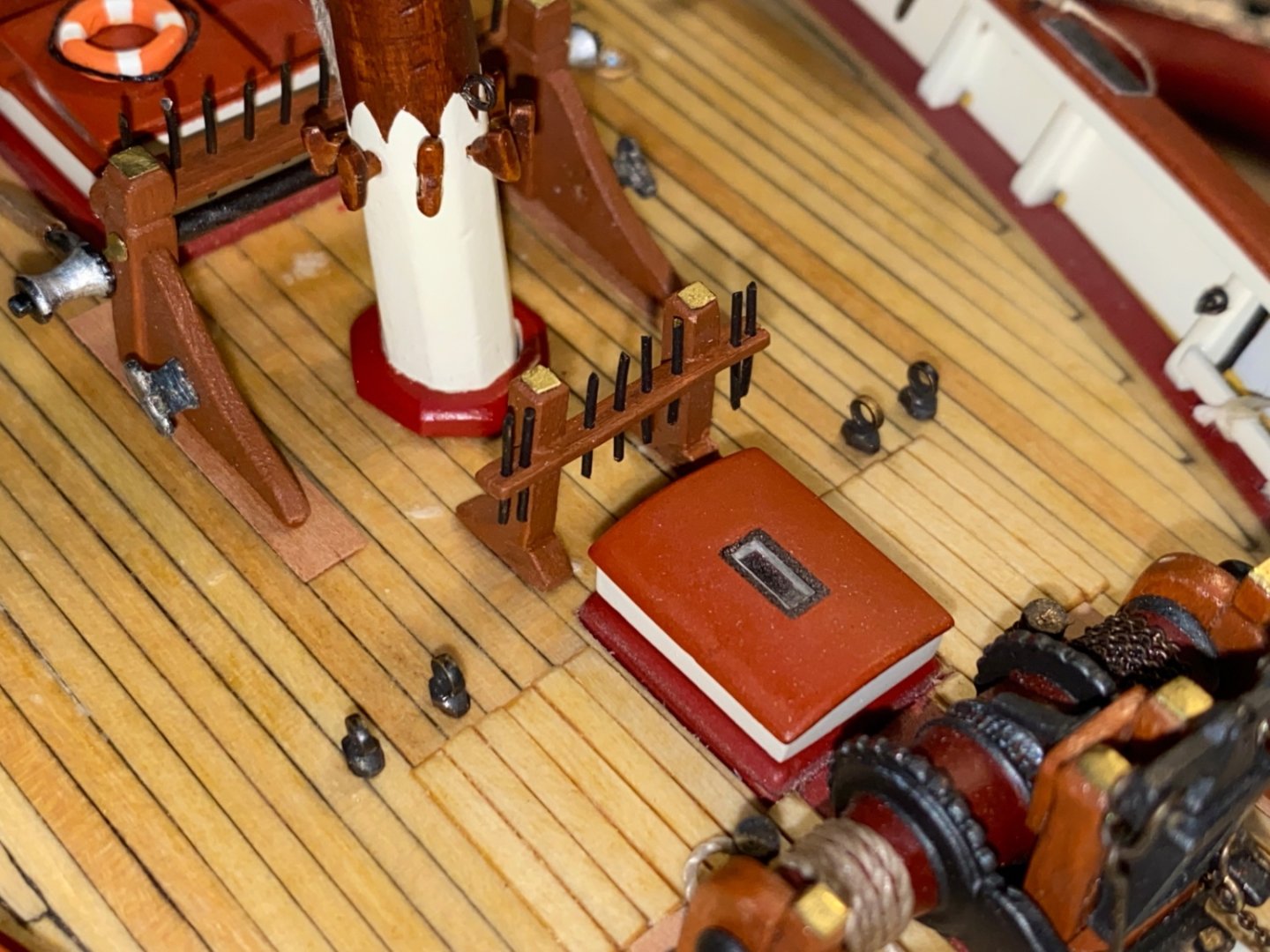
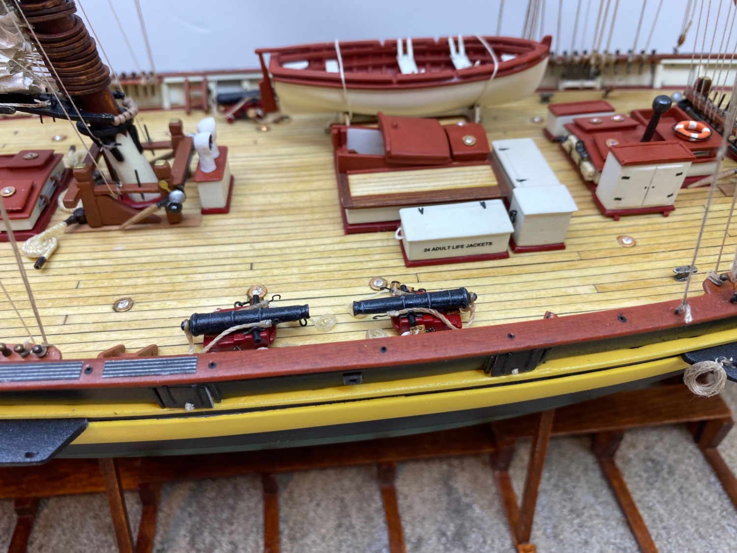
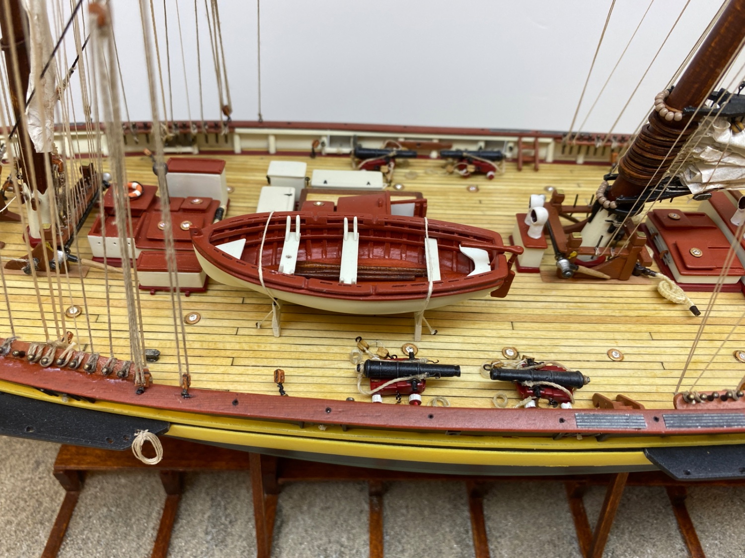
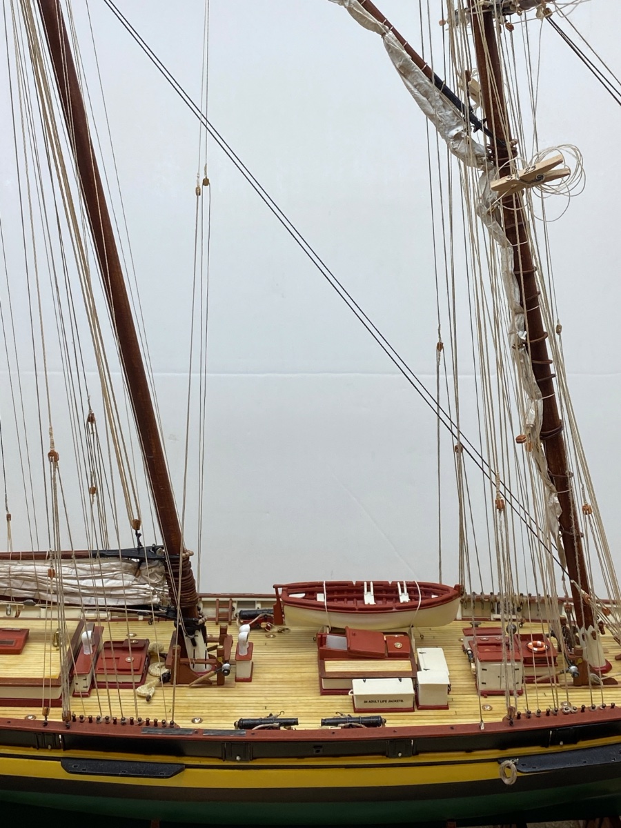
I continued with the remaining details.
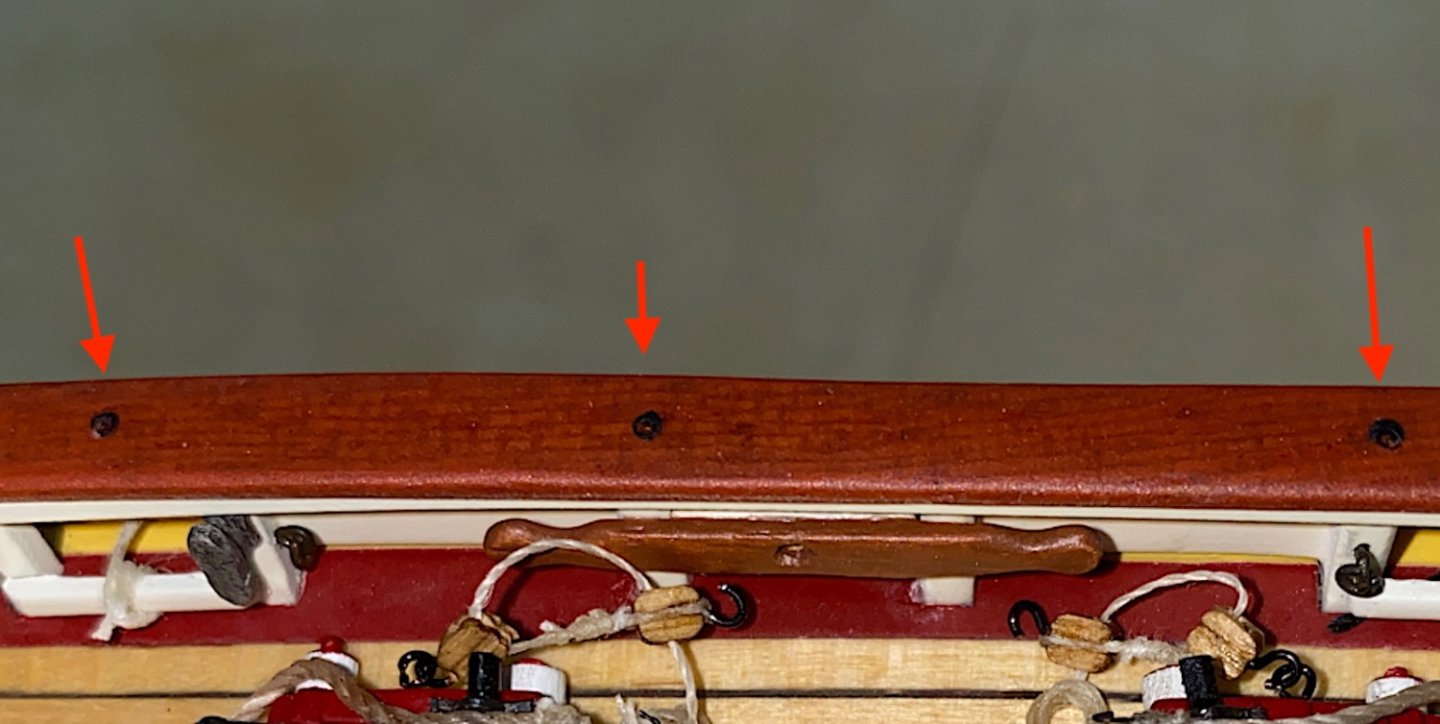
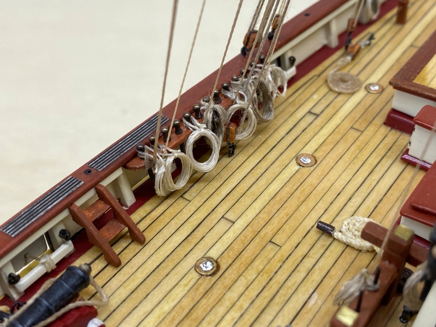
The holes for main rail life line stachions were drilled before. The stachions were prepared from 0.5 mm diameter brass wire. Two wood jig were made. First one was to cut the stachions to the same length. The second one was to set the height of the stachions when they were installed in the holes Here are photos.


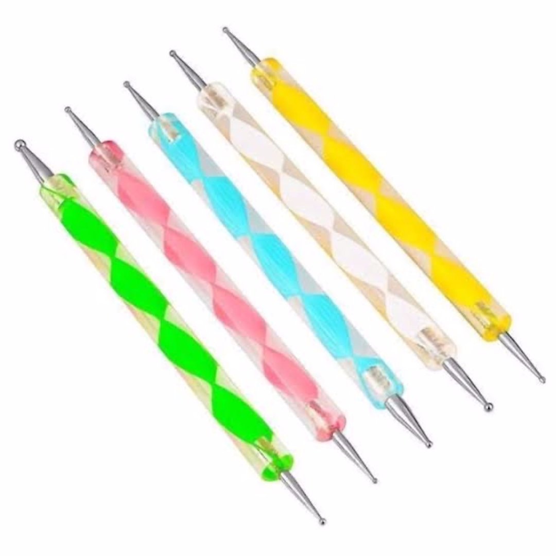
Black circles (red arrows) at the holes were made by 1 mm tip dotting pen using black oil paint. They were made to simulate the collor on the real ship's life line stachion base.
Dotting pens are used for nail art.
Here are some photos of the life line stachions.
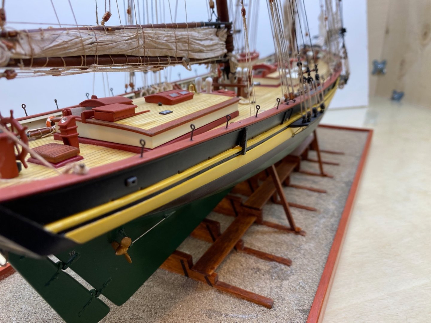
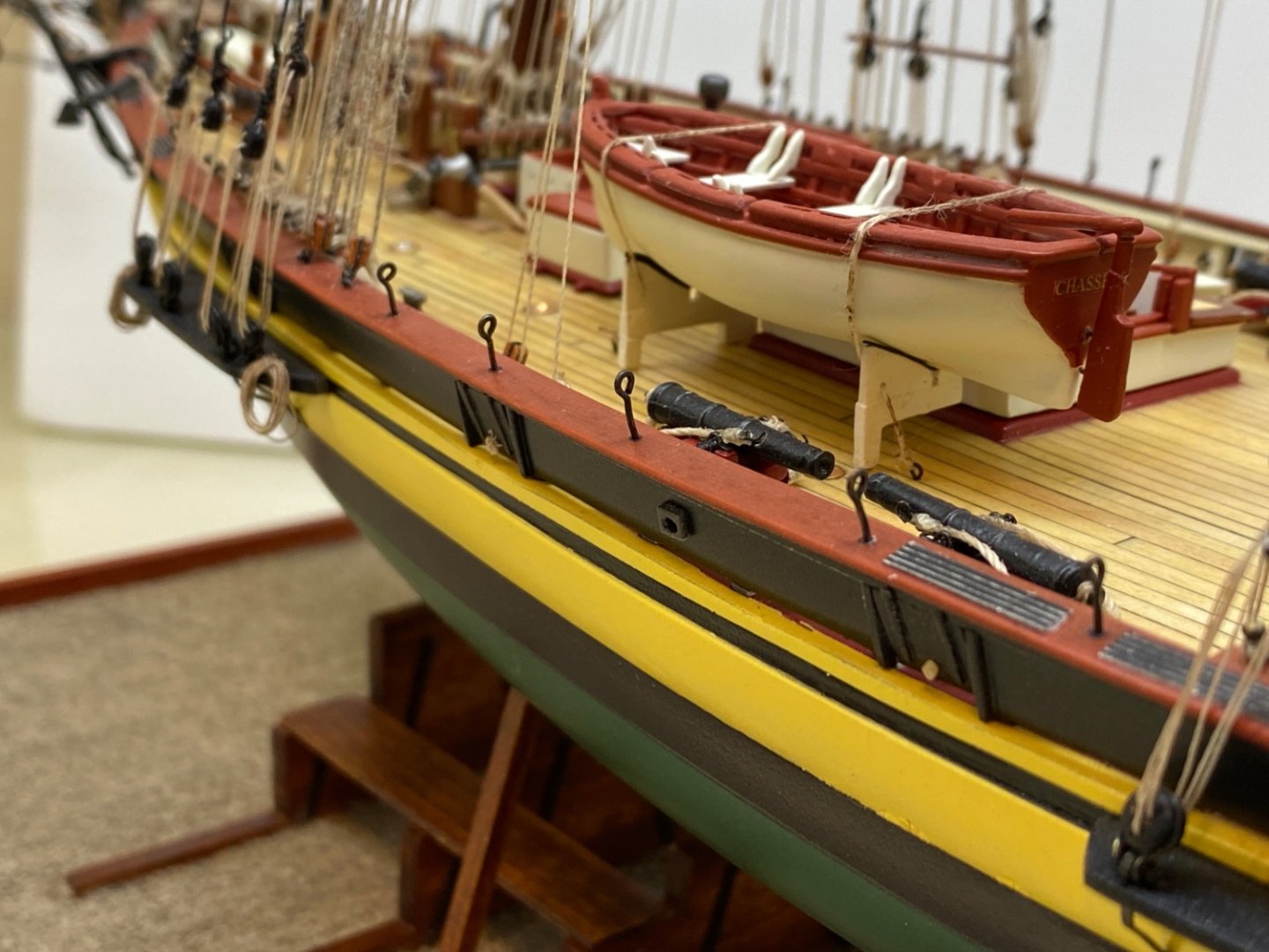
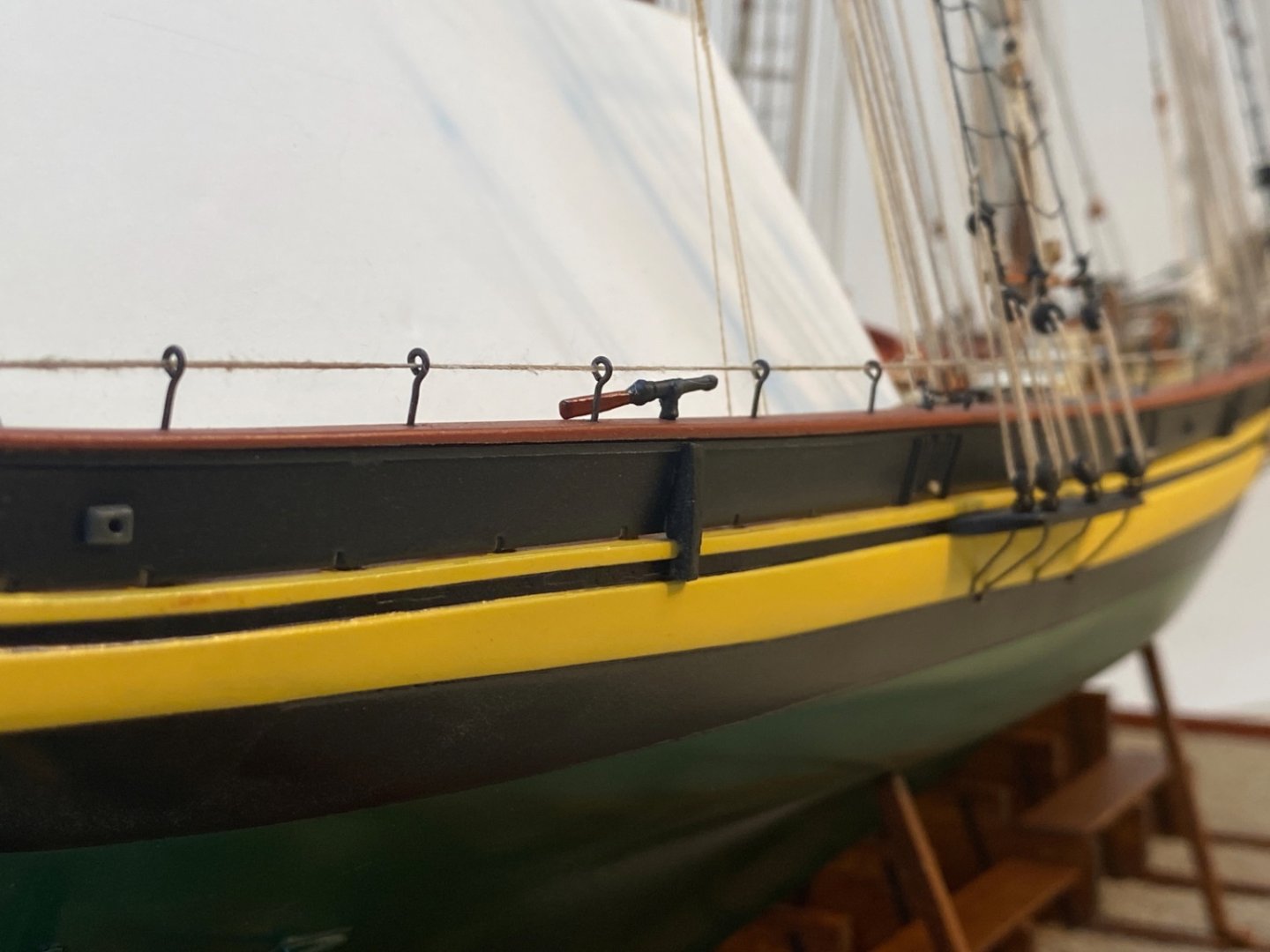
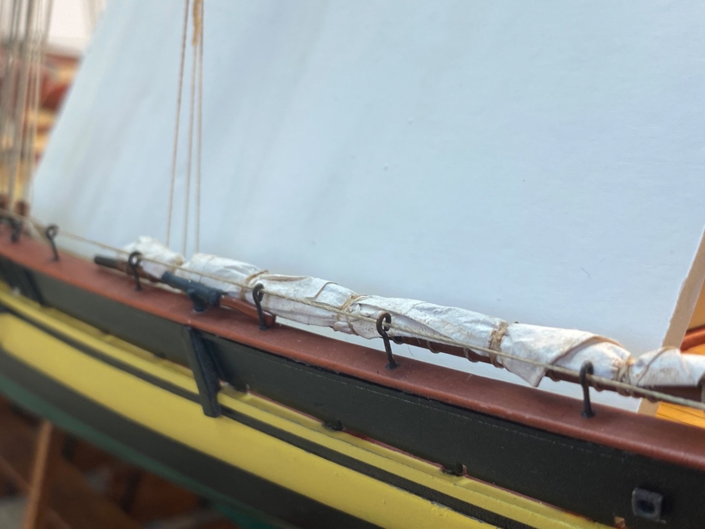
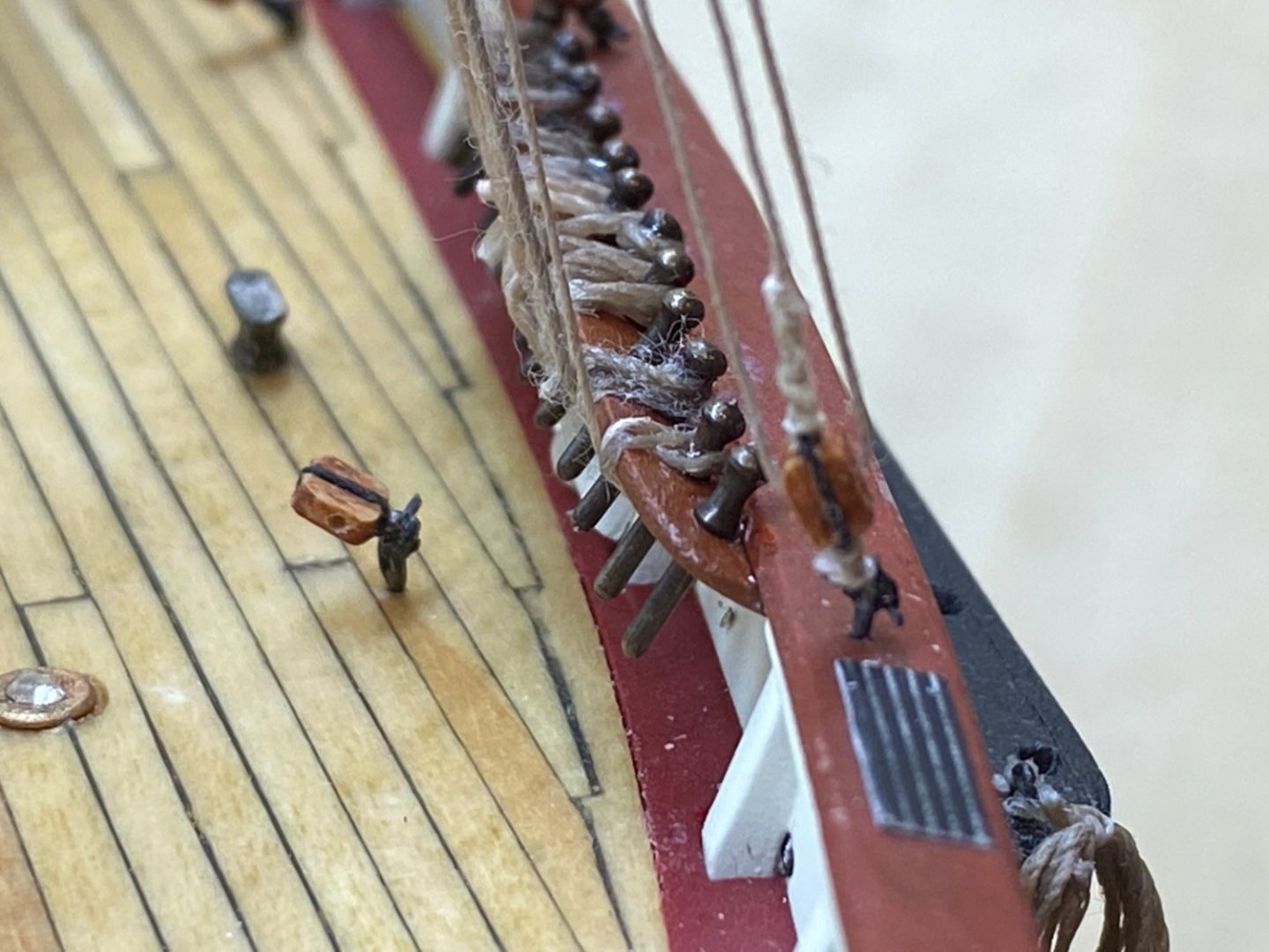
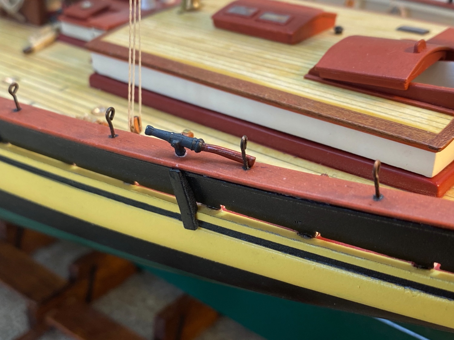
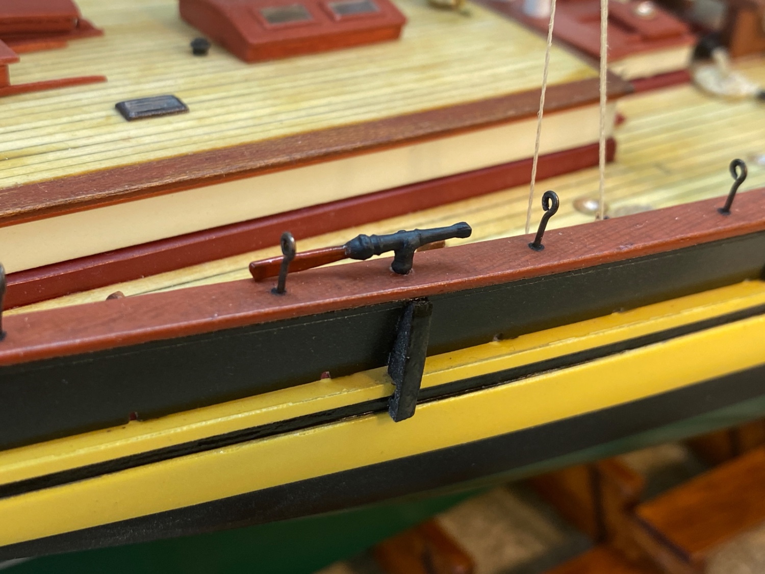
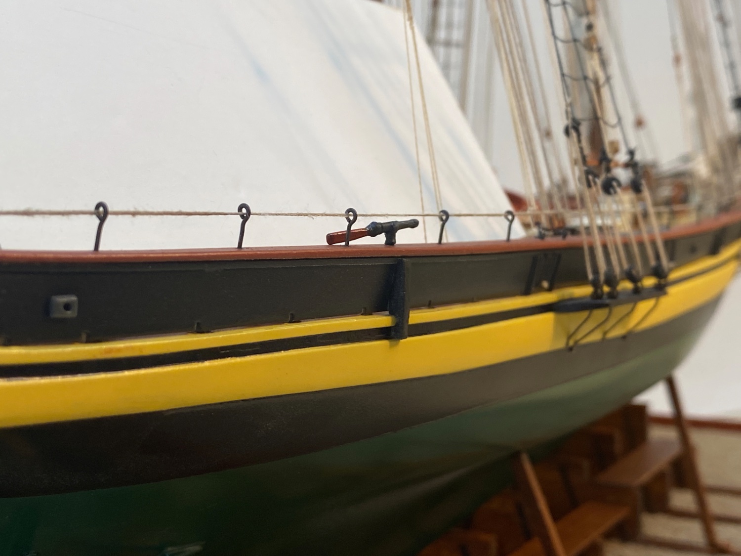
Swivel guns were installed in place.


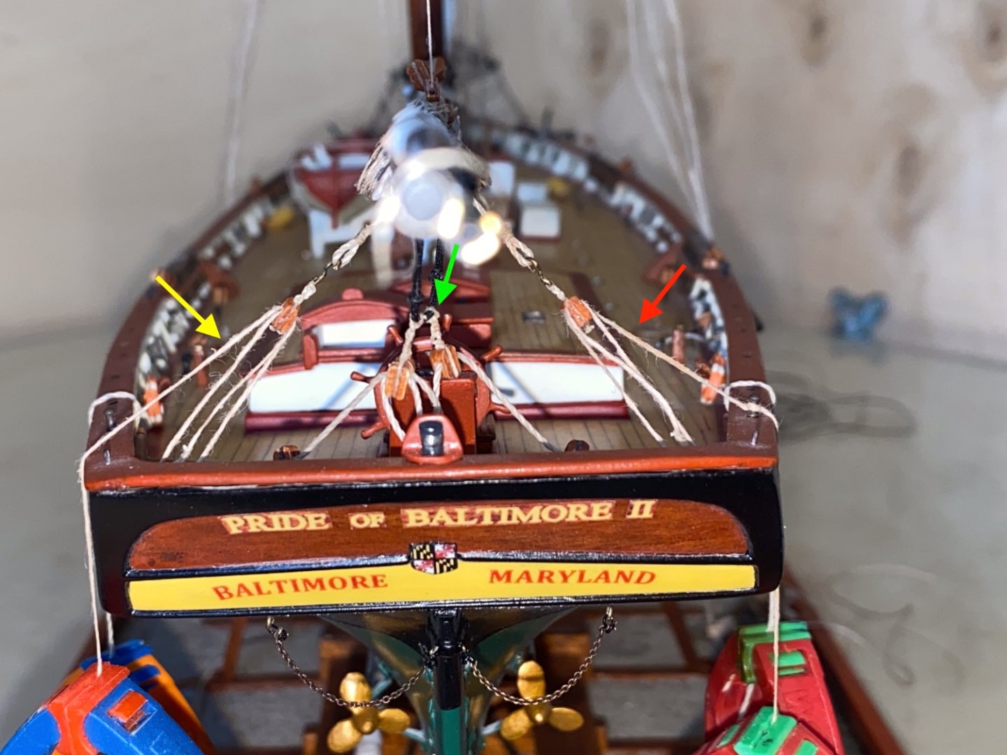
There are 4 cleats seized to the aft lines of all four shrouds. These cleats were much smaller in size than the already modified cleats of the kit stock. Threads were pre-seized to the cleats before their final seizing to the shroud lines in order to make the job easier. Cleats are seized close to sheer poles. Halliards of Ship's pendant, Maryland and Baltimore Flags and signal flags were seized to these cleats.
Seized on the fore lines of the main shrouds was the last rigging of the model. Main Stay hauling tackles were formed and seized.
Finally life line was installed.
There was only one step left to finish the build.
- Prowler901, yvesvidal and ccoyle
-
3
-
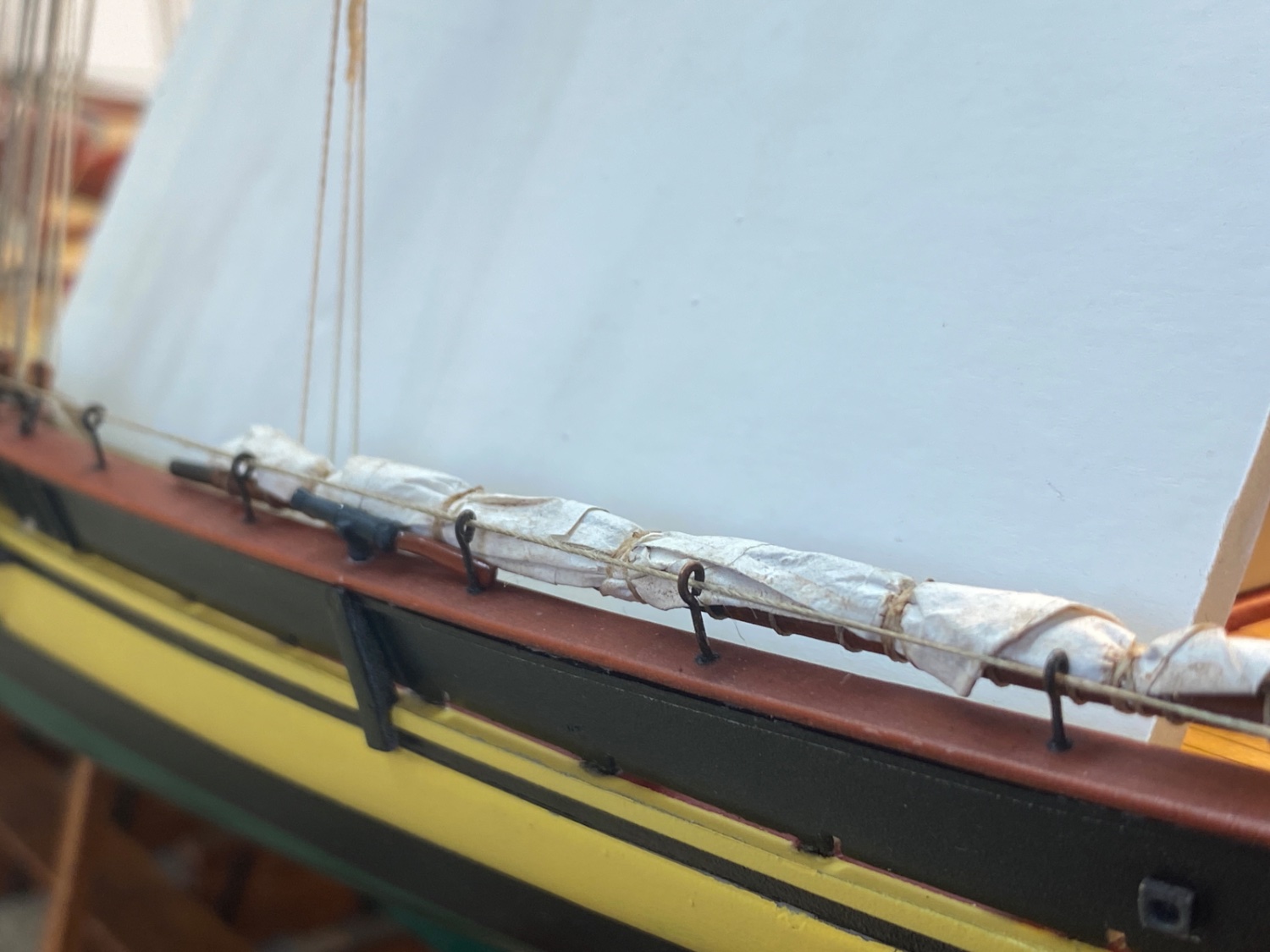
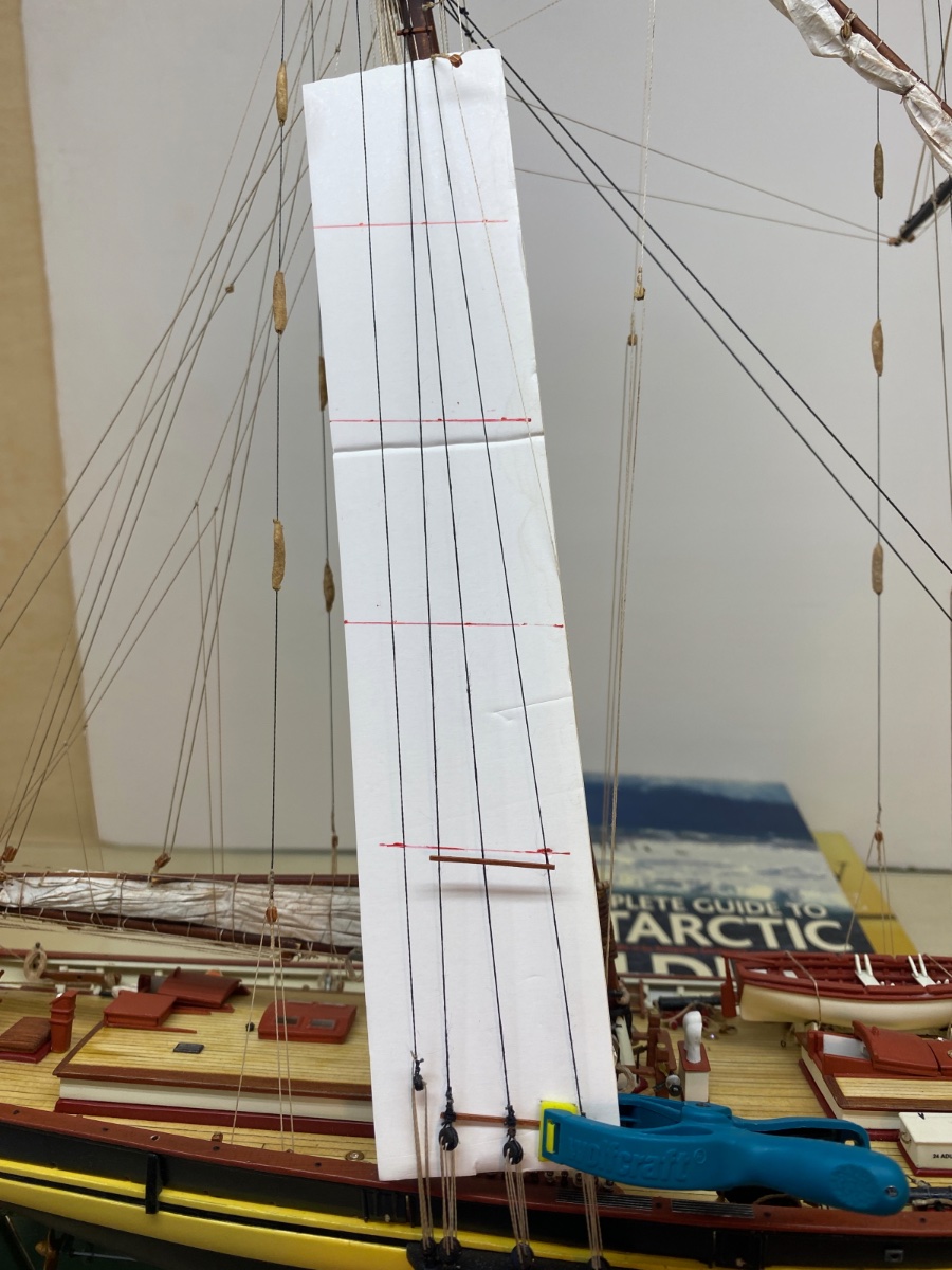
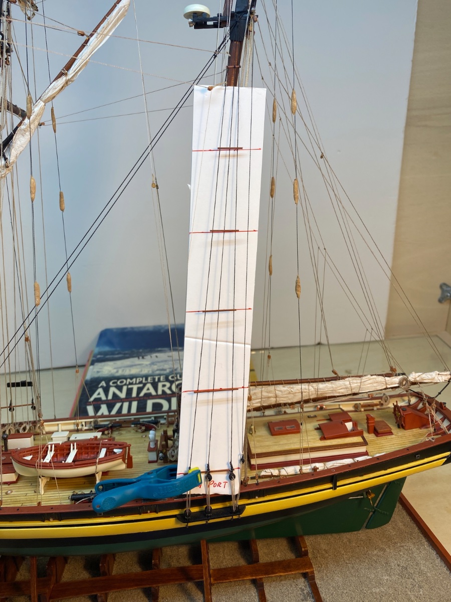
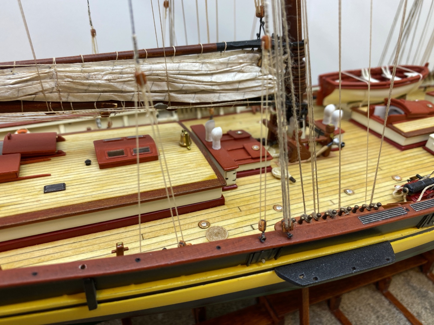
In this step sails , except main sail which was done before, coiled ropes and reachable rigging lines were weathered. Of course it would have been better if this job was done before the target sail and ropes were weathered before. I used Burnt Umber oil paint diluted with a very small amount of turpentine. Weathering was done by dry brushing. Here are some photos of this step . Pre and post weathering photos are presented together. The first photos are before weathering.
Forestay sail port view

Forestay Sail starboard view
Jib and Jib Topsail port view

Jib and Jib Topsail starboard view

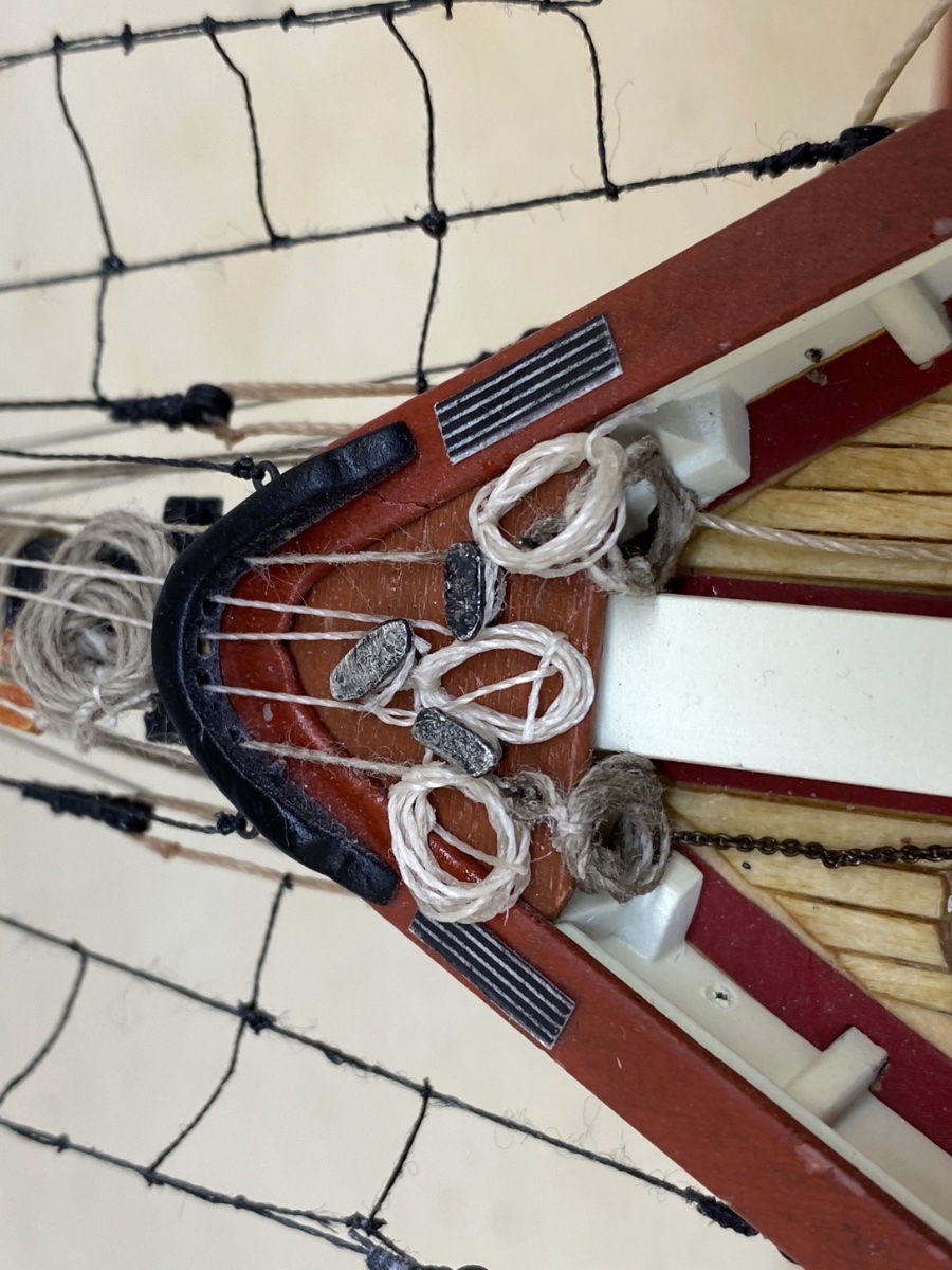
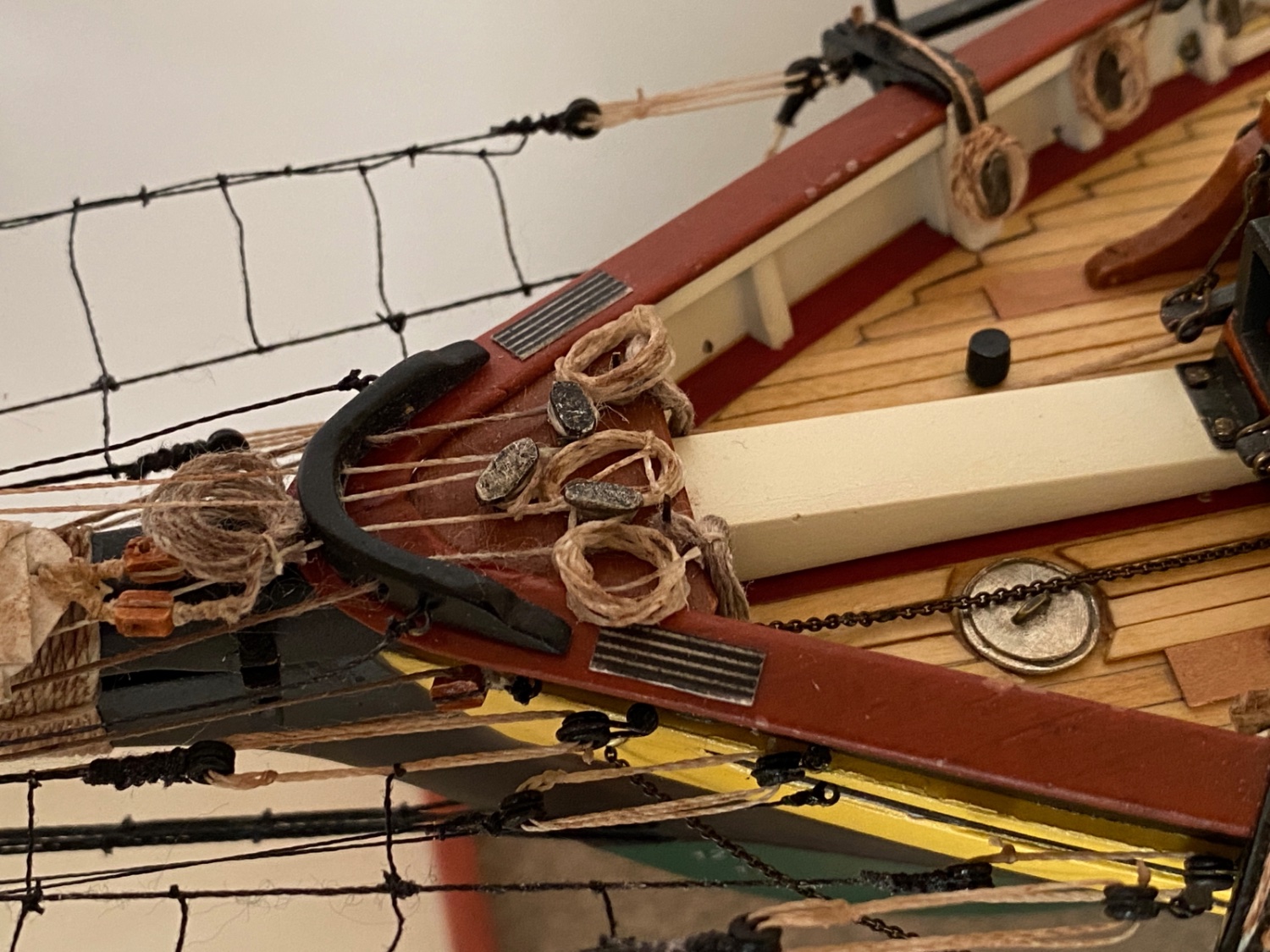
Pin and cleat platform at bow


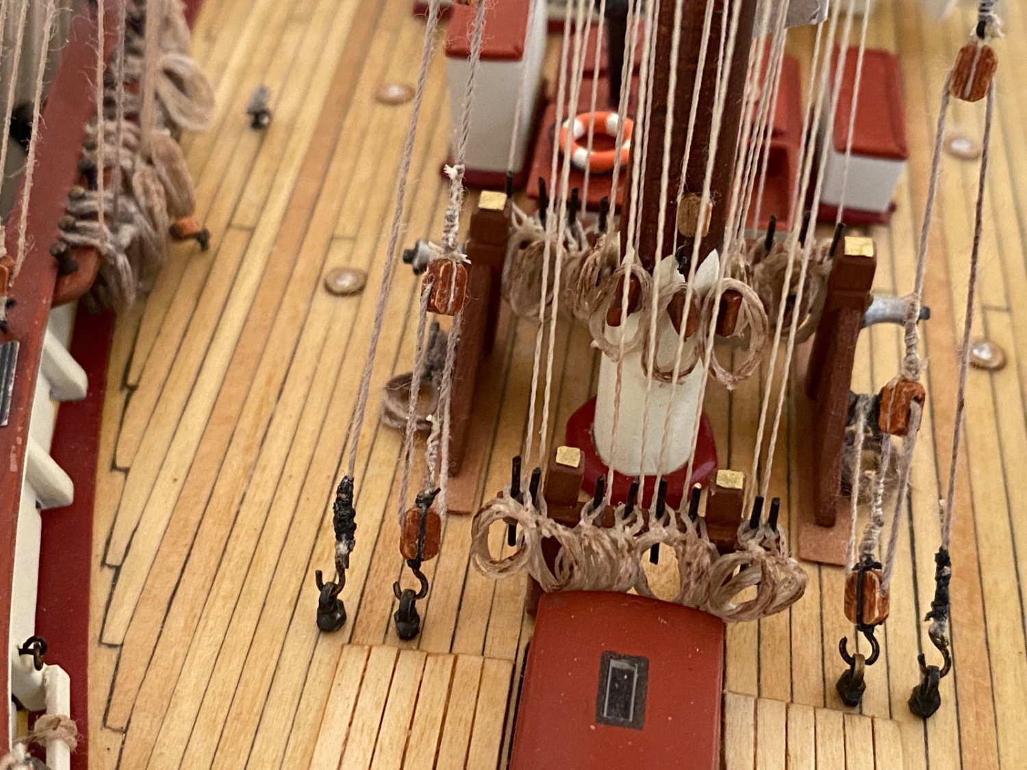
Fore mast fife rails

Starboard fore pin rails

Port fore pin rails


Starboard main pin rails
Port main pin rails

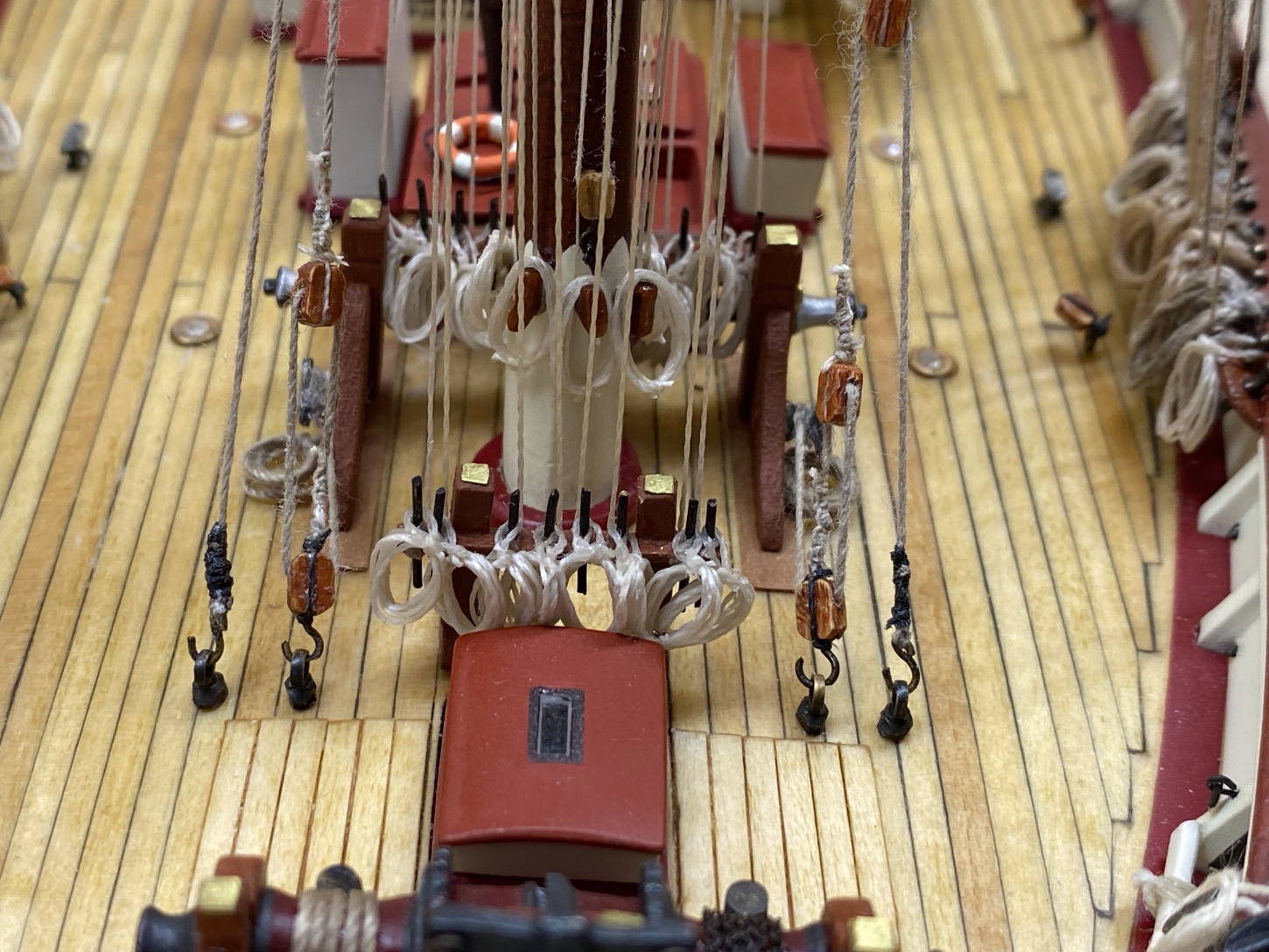
Main mast fife rails


Port view of main sheet and boom guy rigging
-
1 hour ago, allanyed said:
Hi Halit
I don't know how easy or difficult it is to get rope rather than thread in Türkiye but making proper rope is not a difficult task if you cannot buy it easily where you are located.. For the future, there are inexpensive ropewalks including the one from Syren, or you can get some gears and make your own ropewalk. If you look at the string you used and miniature rope in the photos below you can see there is quite a difference in appearance.
Cheers
Allan
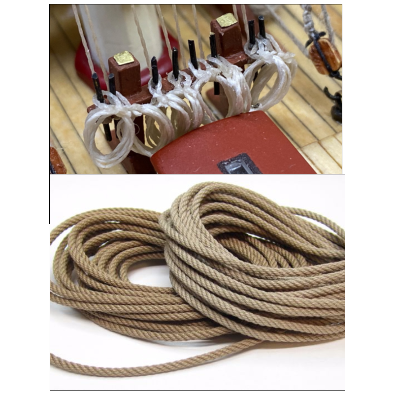
Hi Allan
Thanks for your comment. The difference is enormous and you are quite right.
I am aware of the Syren company and also rope walkers both commercial and diy ones. However this model was my first experience with rigging and I did a lot of mistakes during the build. Not understanding the rope/thread difference was one of them. I checked the websites and especially Syren with admiration, a lot of times. But with the current exchange of Turkish lira agains US dollar ( 1 US : 19 TL)as well as the shipping and import costs, I hesitated for the purchase. A large amount of my kit stash and tools were purchased during my visits (No shipping and no import tax) to US when my son was there and US/TL exchange was around 1:4. However in the future projects I am sure I will solve this problem..
PS: In the next post the ropes will be weathered and look a little bit nicer ...
Halit
-
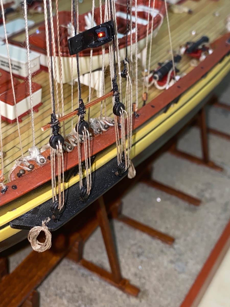
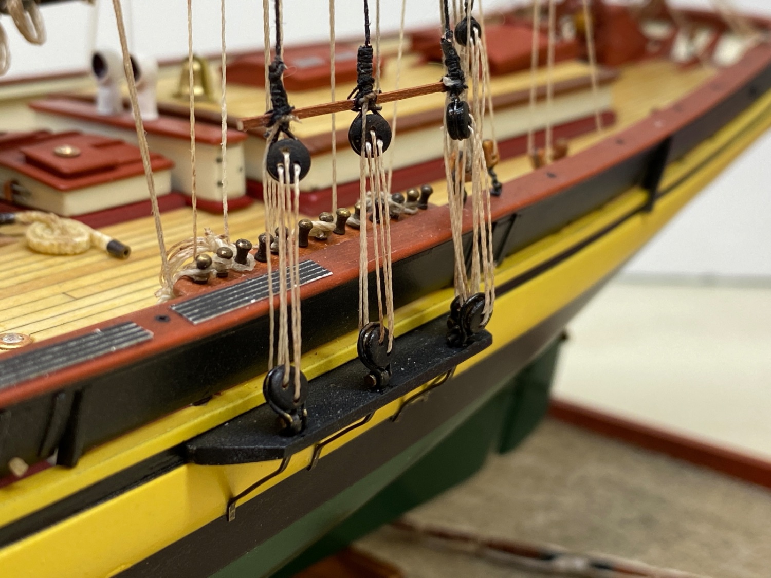
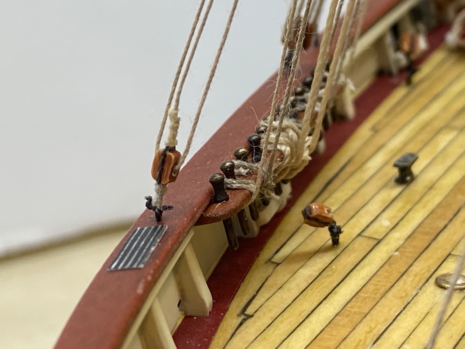
Topmast backstays, main and fore shrouds were the remaining standing rigging.
In one of the previous I posted the photos of lower deadeye stropping and chain plates. Here are them again as a reminder.

Shroud line lower deadeyes with chain plates.
Topmast Backstay line lower dead eyes
Those deadeyes were painted black.
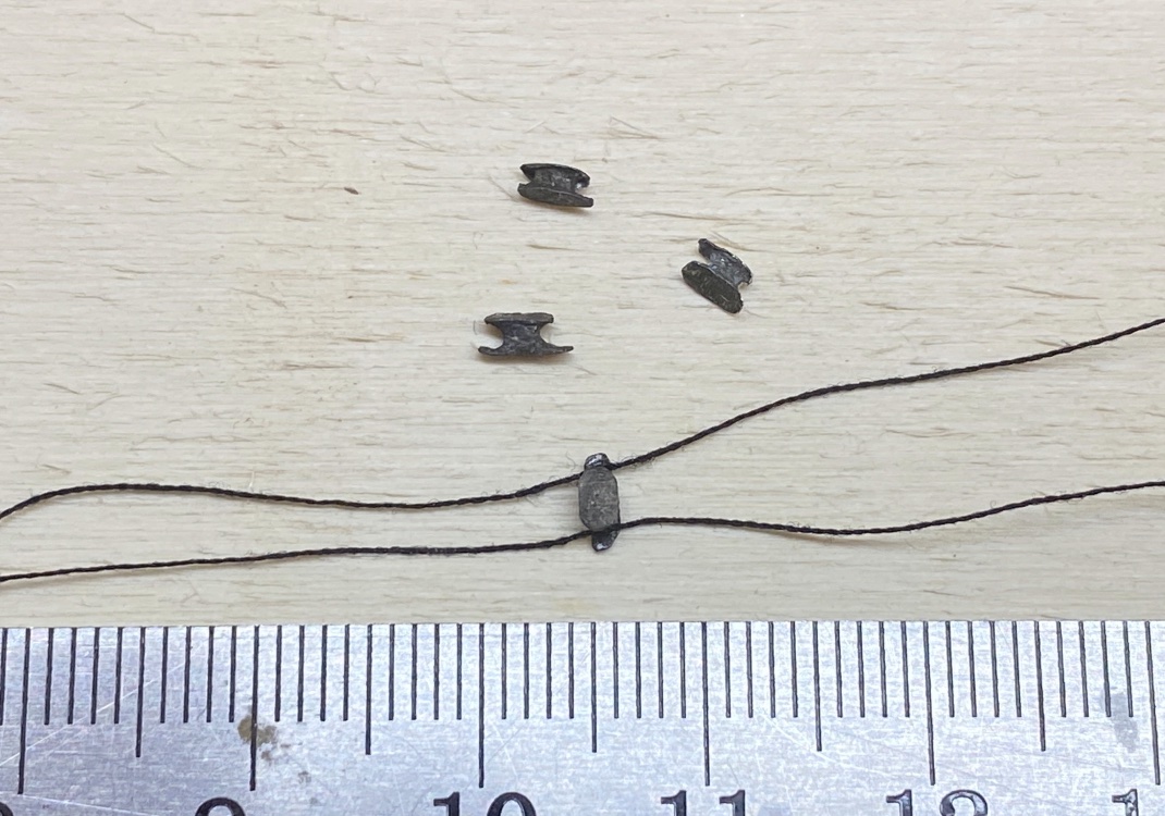
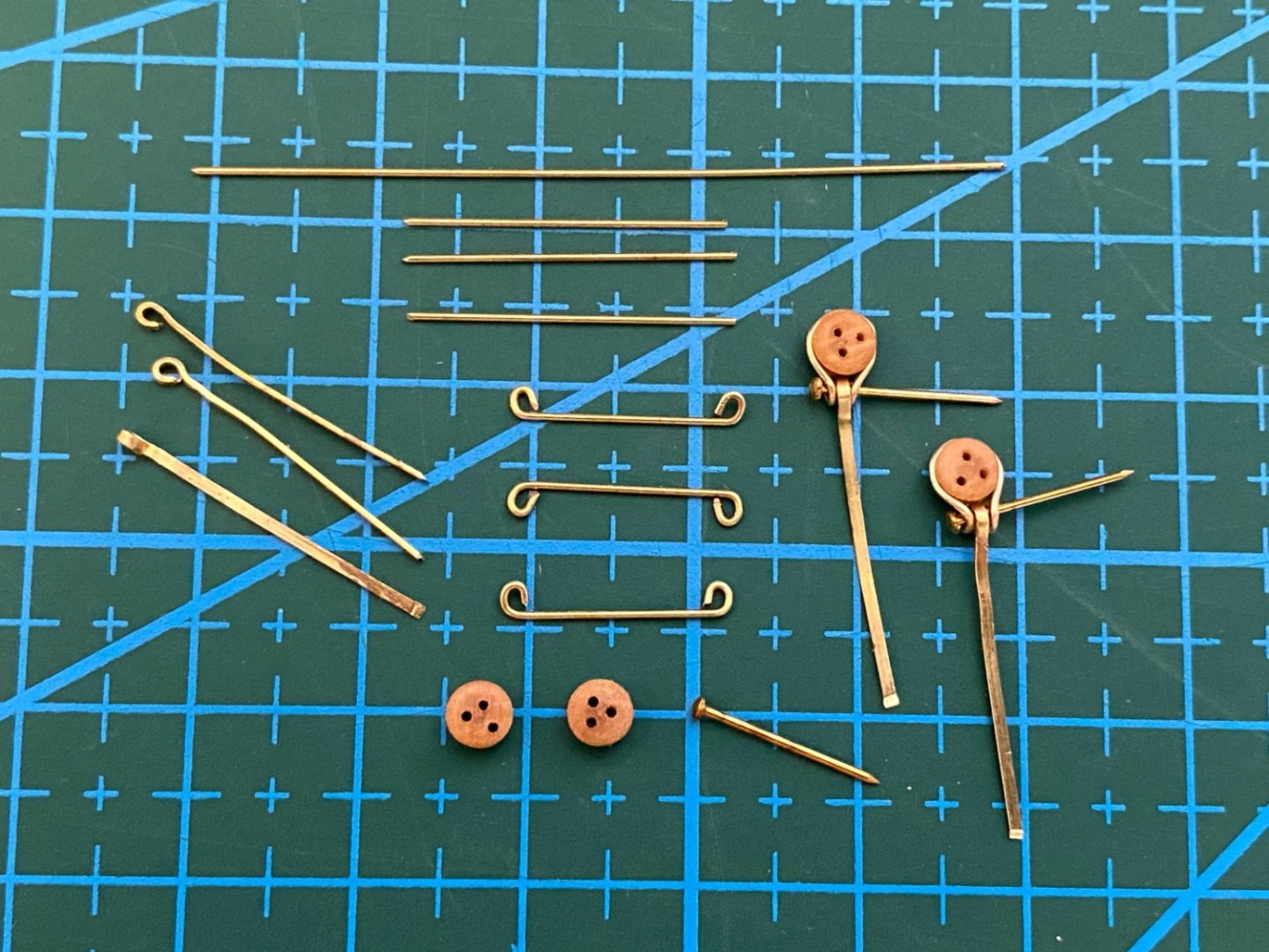
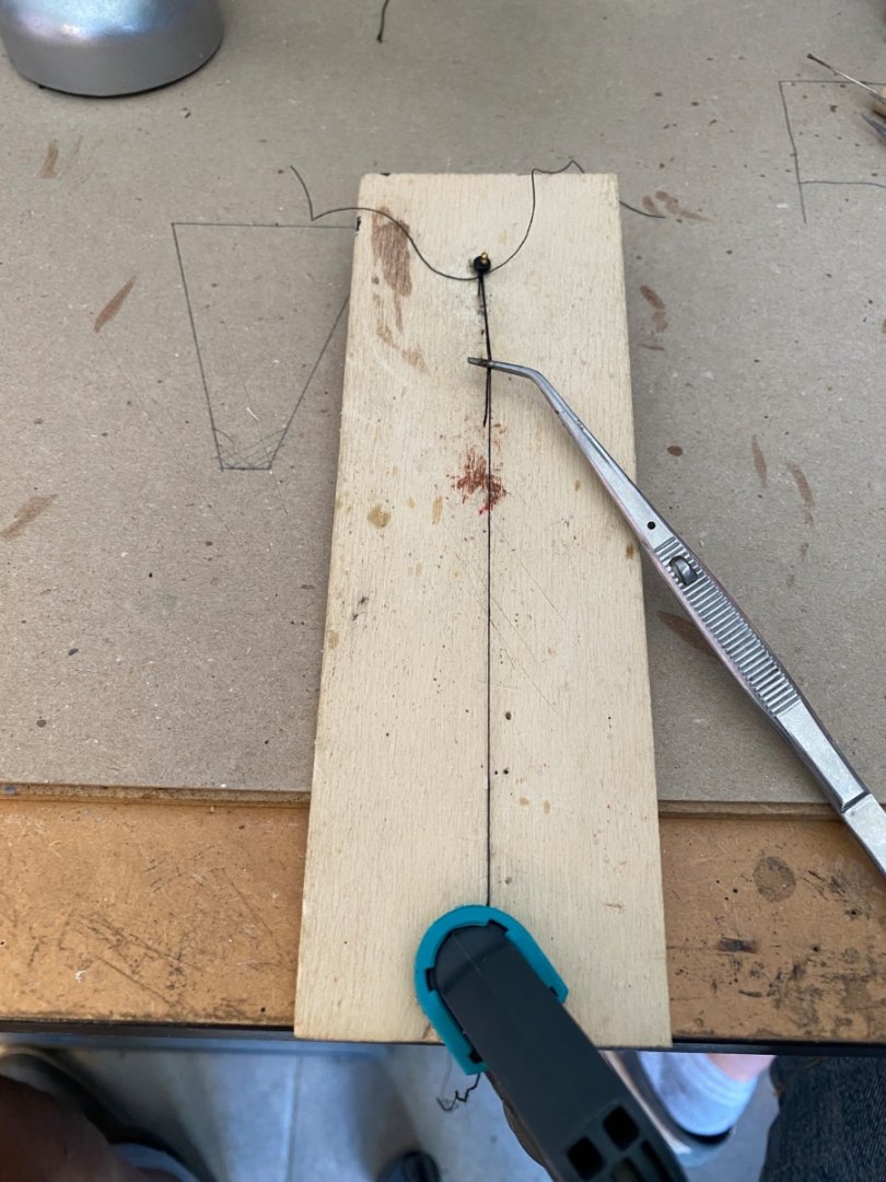
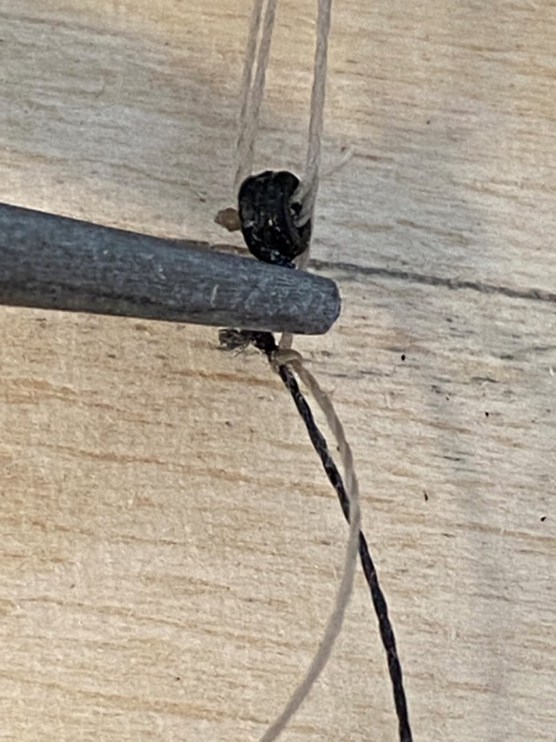
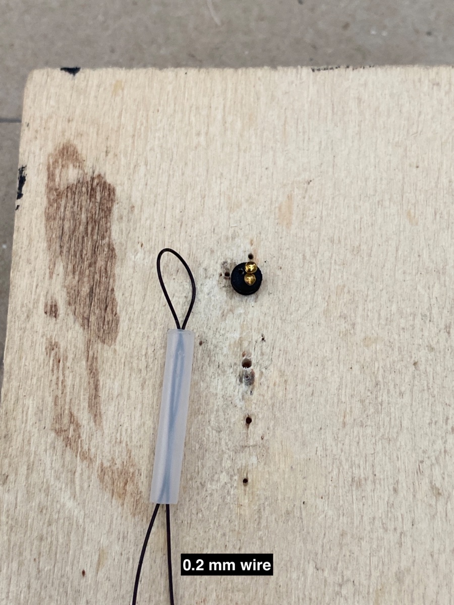
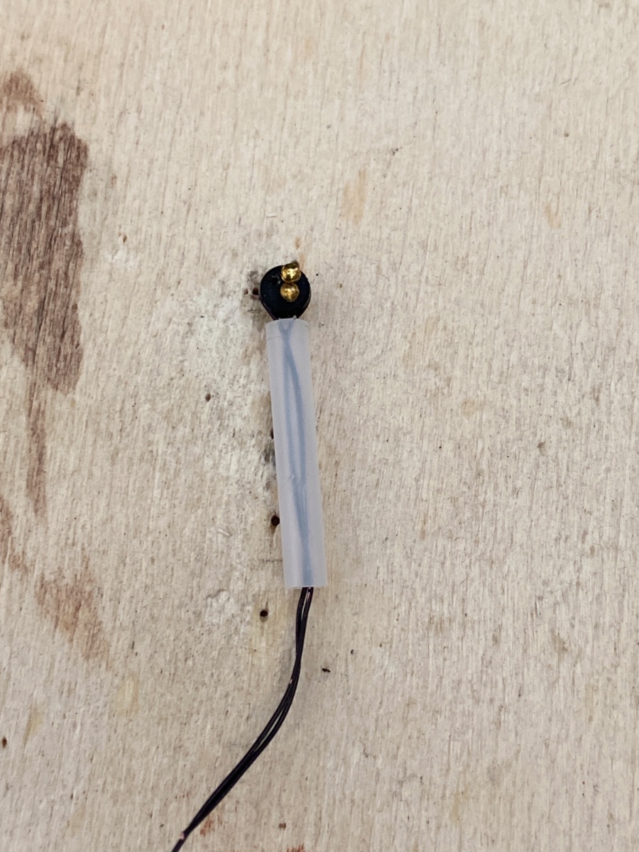
The next step was the preparation of the upper deadeyes. Just like the lower ones, they were also stropped with wire but with 0.2 mm black one. Here is how I did it. Photos probably be self-explanatory. Please note that the deadeyes were fixed to the scrap base wood by two nails.


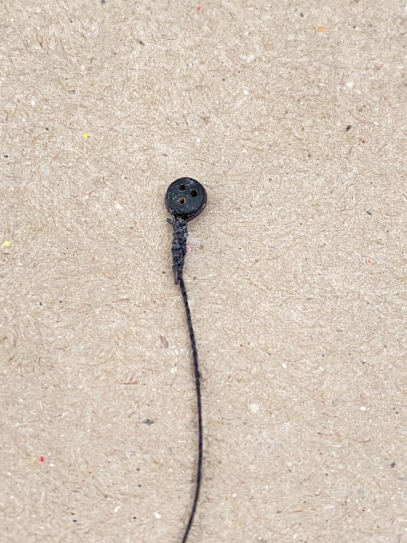
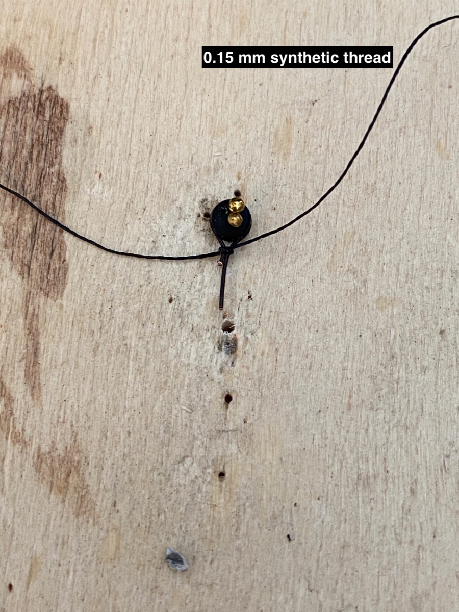
Then an overhead knot with 0.15 mm black synthetic thread was tied as close as possible to the deadeye and strengthened by a touch of CA glue. The wire was cut to size as seen in the photo . 0.3 mm black thread used as the rigging line was passed through the small opening between the knot and deadeye.
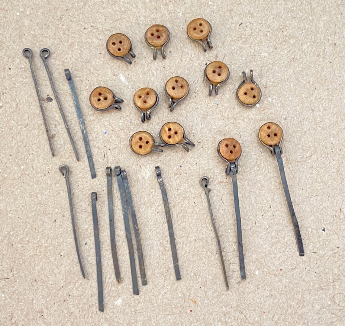
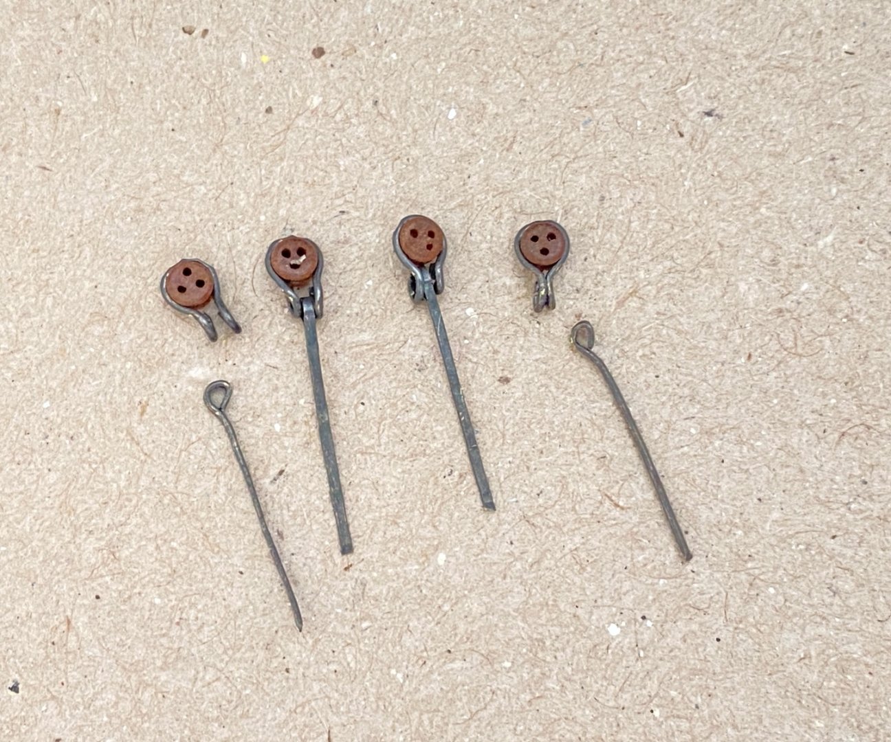
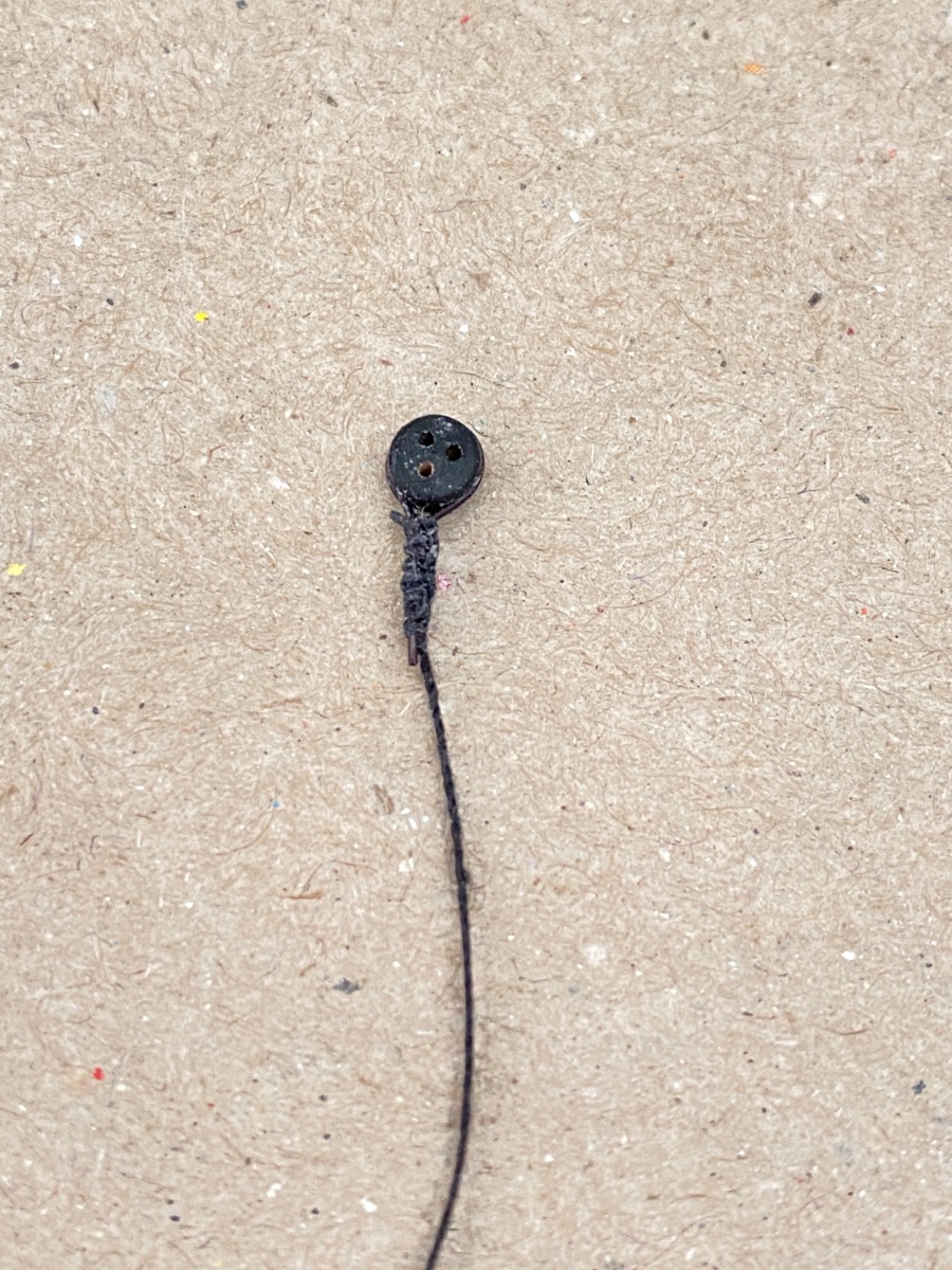
Seizing of the rigging line and the remaining wire was done with 0.15 mm synthetic knot thread. The seizing was not textbook done . I made alternate continuous knots with one end of the 0.15 mm thread , which later found out that the technique was called ' Mississippi Whipping'.
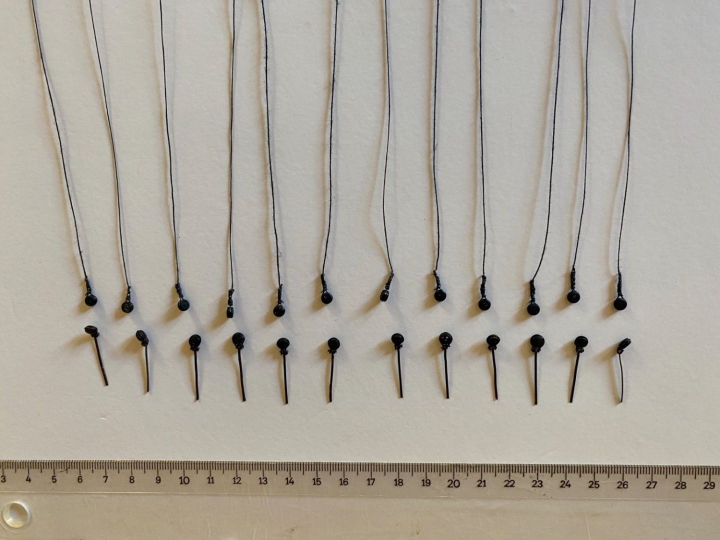
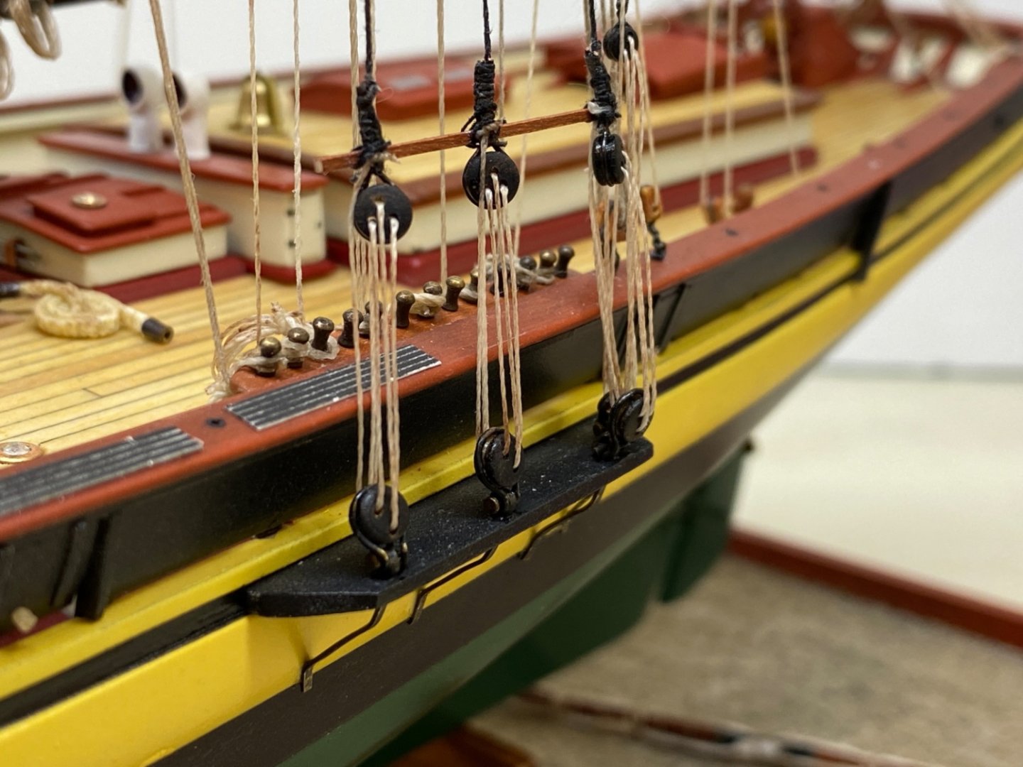
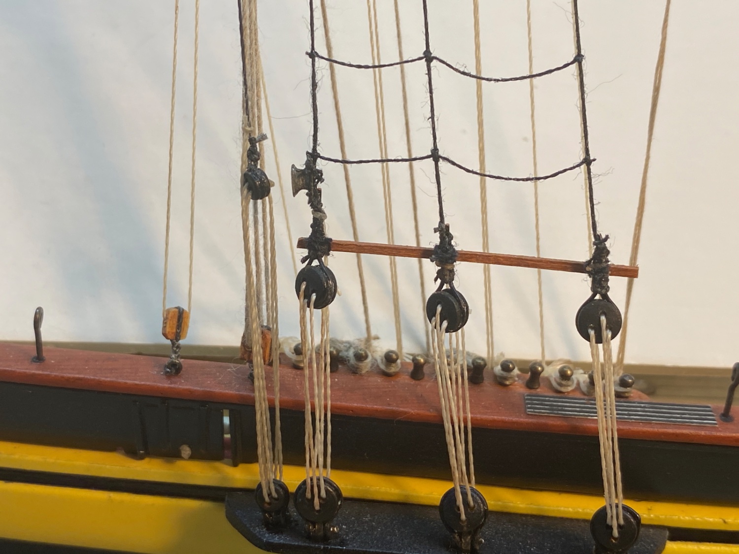
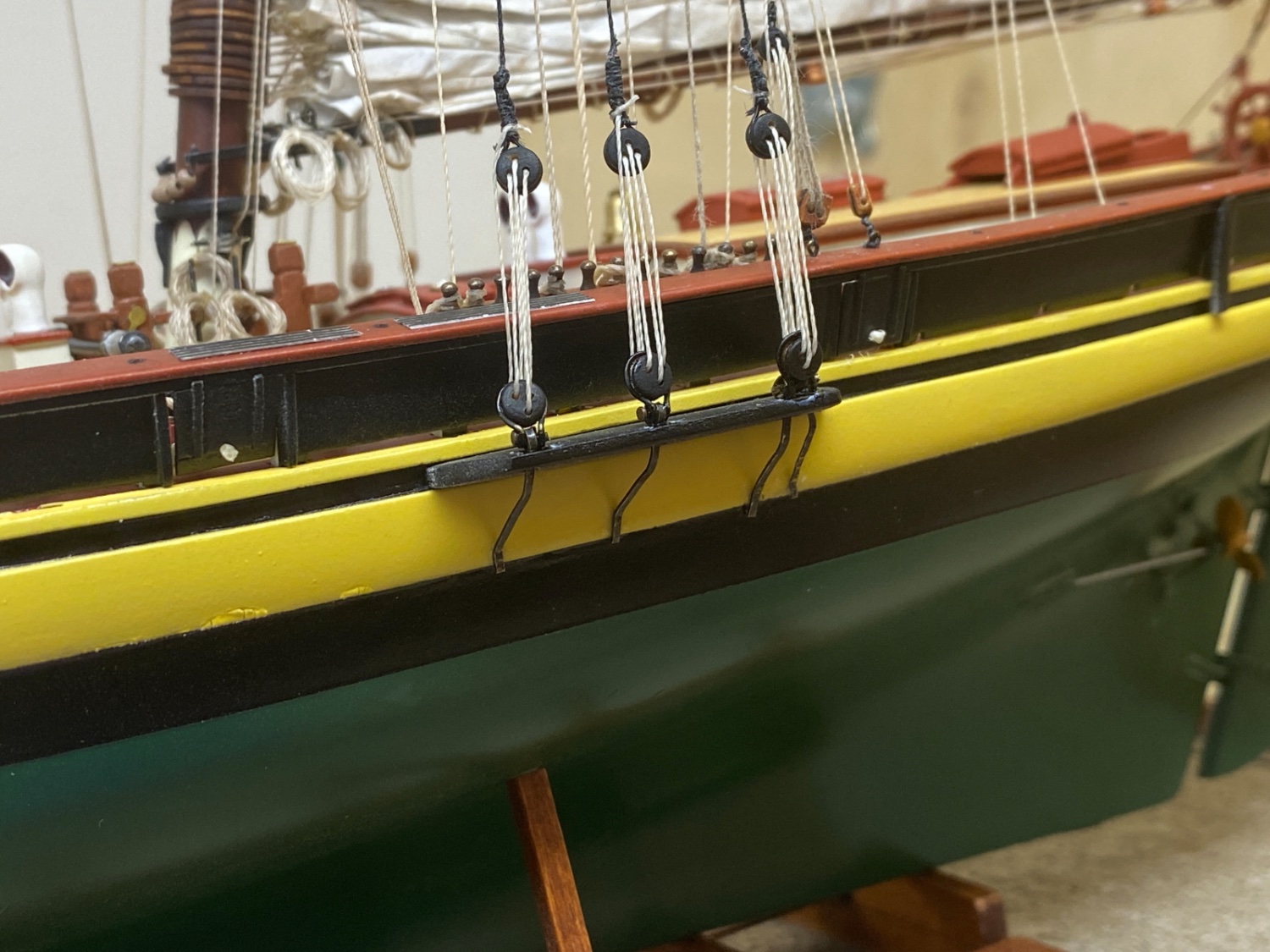
All the upper deadeyes were seized to riggings lines. Here you see the lower deadeyes with chain plates and upper dead eyes with rigging lines for shrouds.
The chain plates of the lower deadeyes were dry fitted and were given their final shape and length. This was done to each and every chain plate. All the shaped chain plates with deadeyes were put aside with their exact location marked.
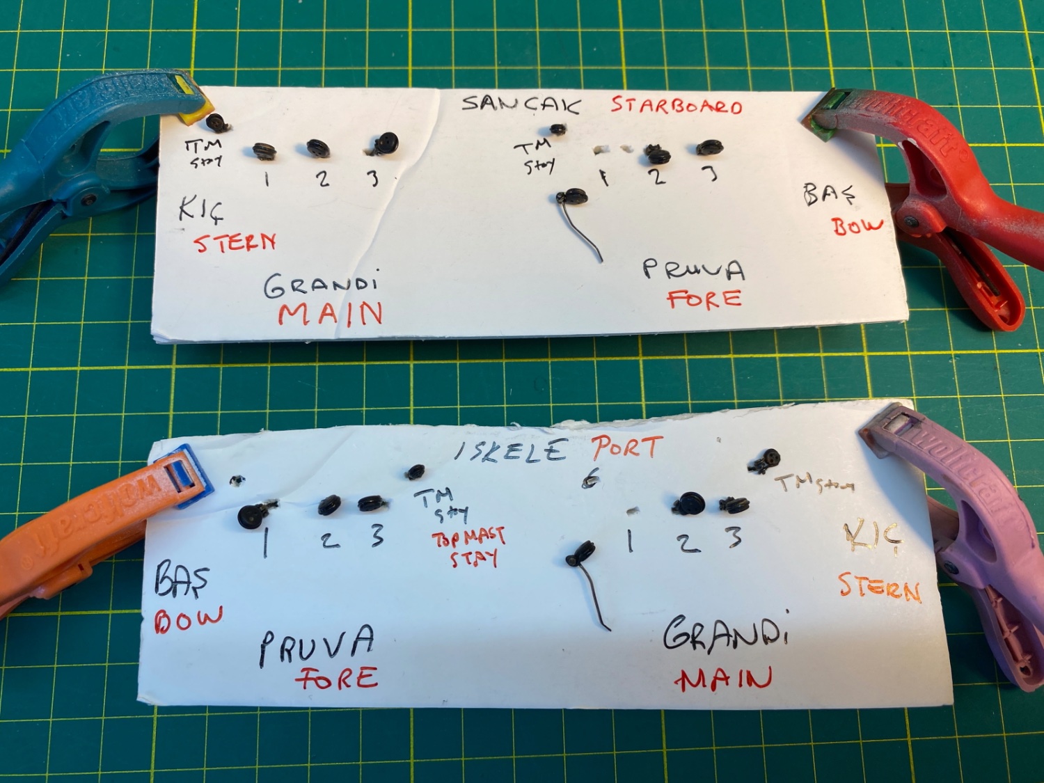
Please disregard the Turkish terms in the below photo.

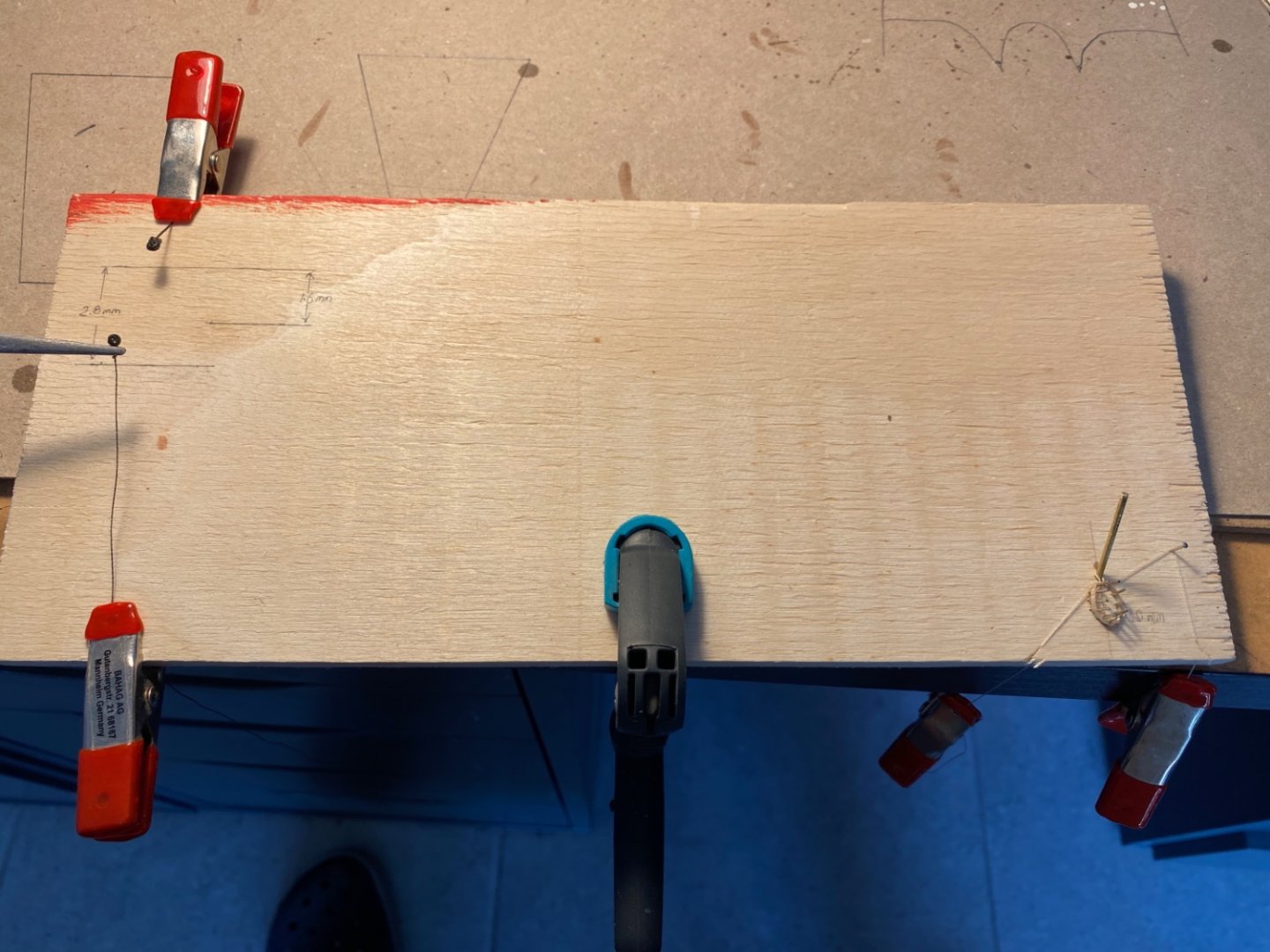
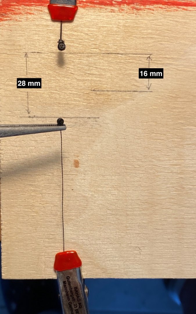
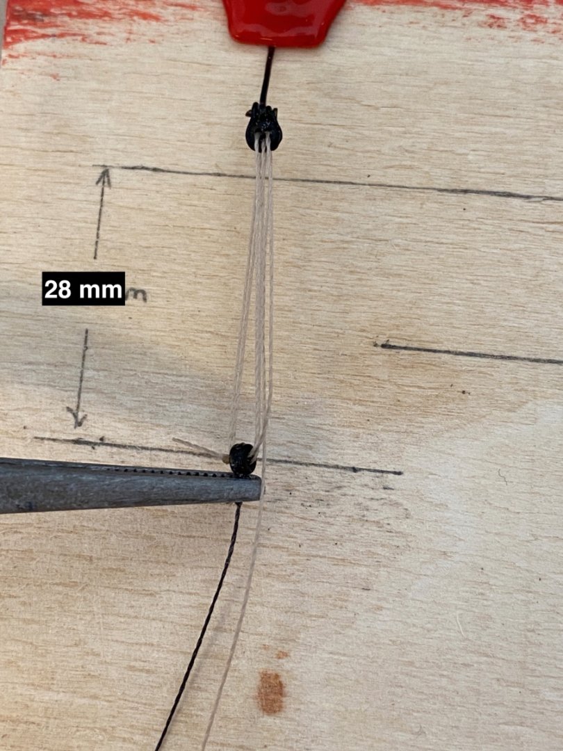
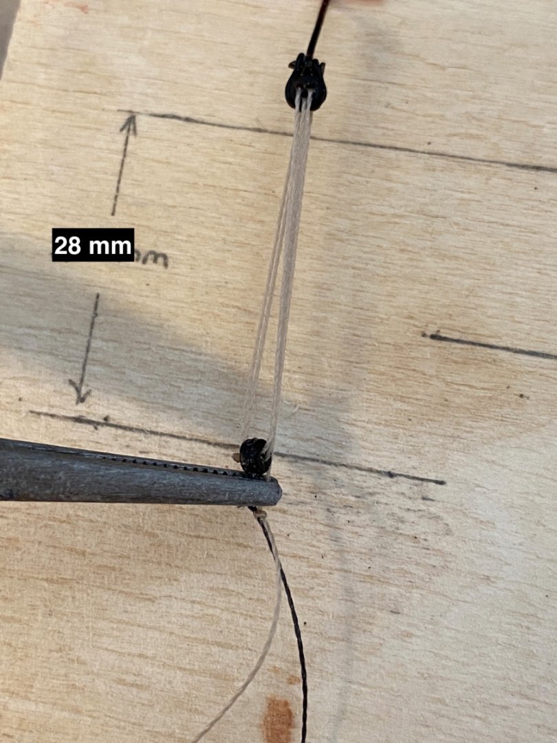
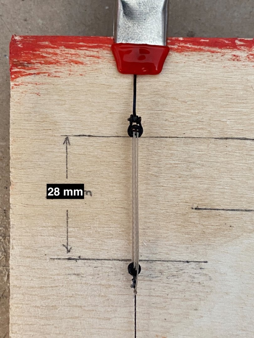
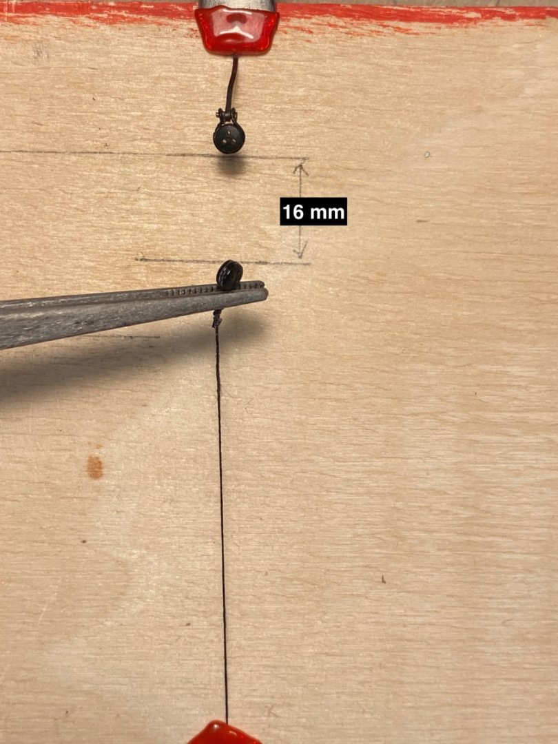
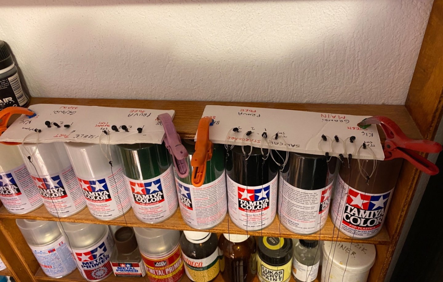
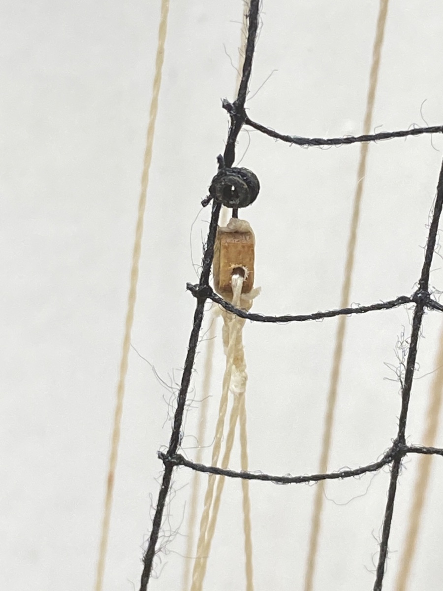
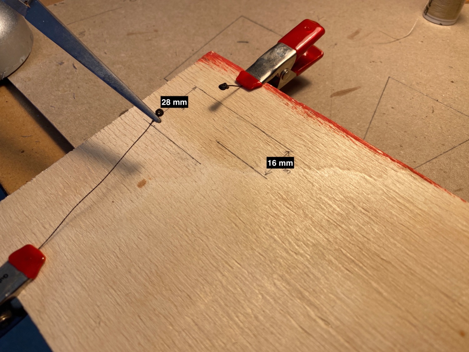
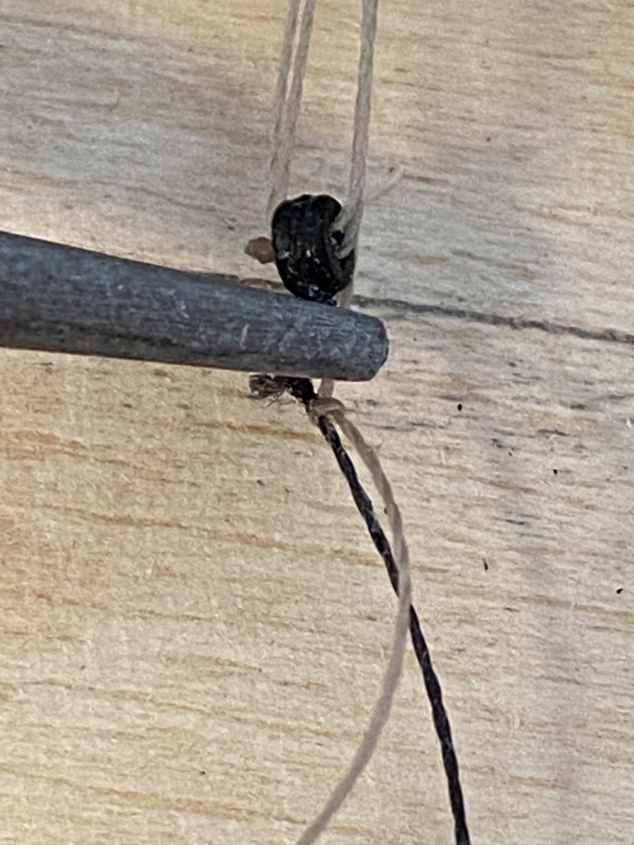
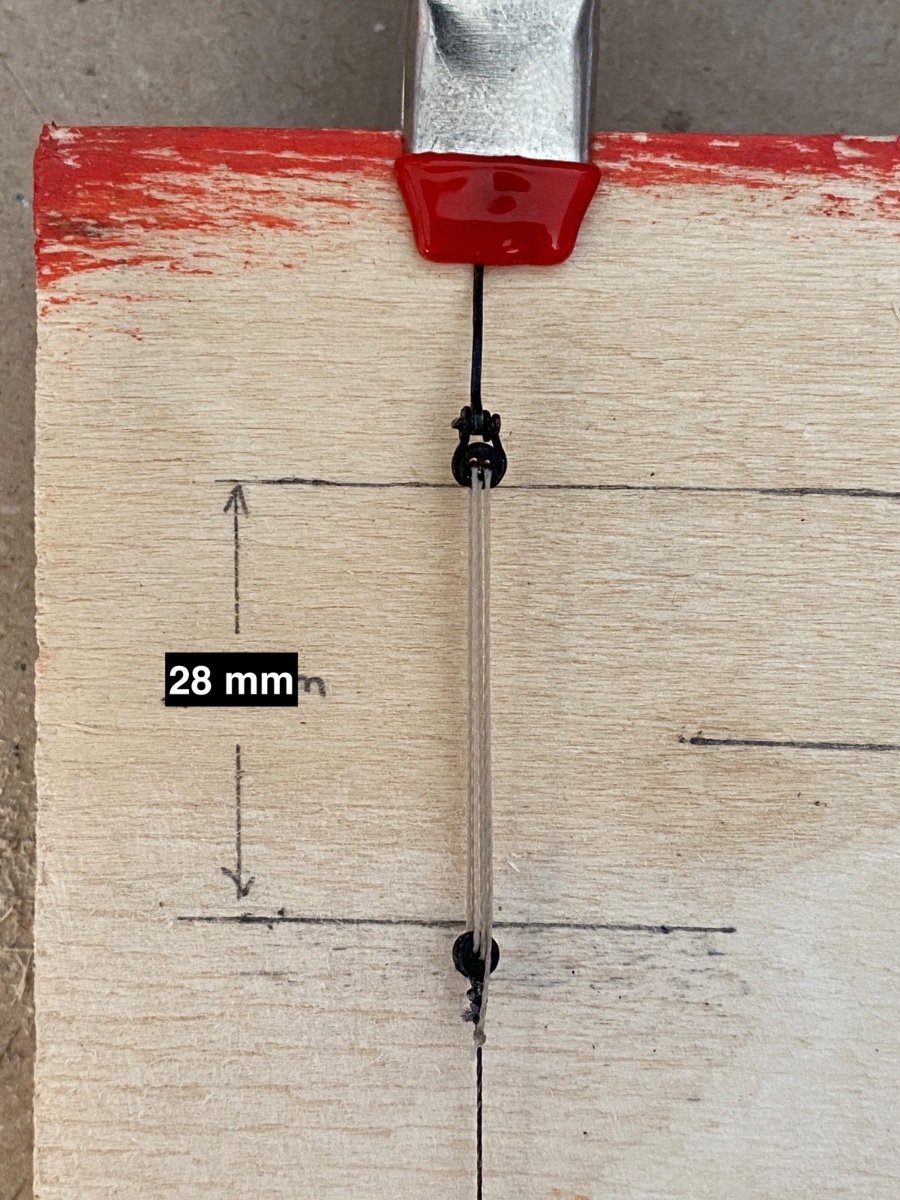
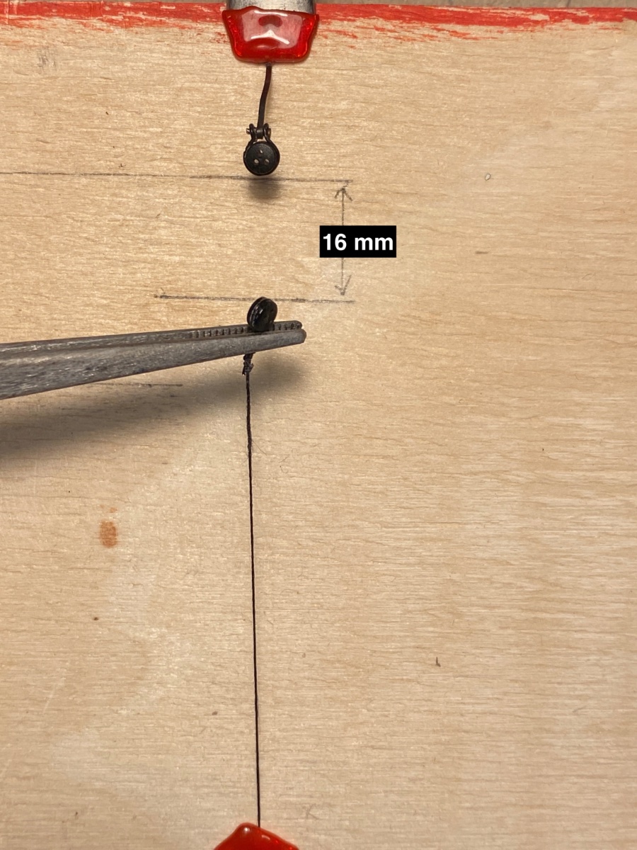
The next step was the reeving of the lanyards. In order to maintain a uniform distance between the lower and upper deadeyes I chose to do this step before the shroud lines were seized to mast heads. At one corner of the jig board which the other corner I used for experiencing Tom Lauria's method for coiled ropes, I prepared a 1:1 scale plan for the distances between shroud deadeyes (16 mm ) and Topmast stay deadeyes (28 mm) separately . The lower deadeyes were fixed at the top of the jig board with a clamp. A self retaining tweezer was holding the upper deadeye and shroud line thread was fixed by another clamp to the base of the jig board. 0.2 mm tan colored synthetic thread was used for lanyards. After reeving all the lanyards, all the prepared lines were put in their location indicated places.

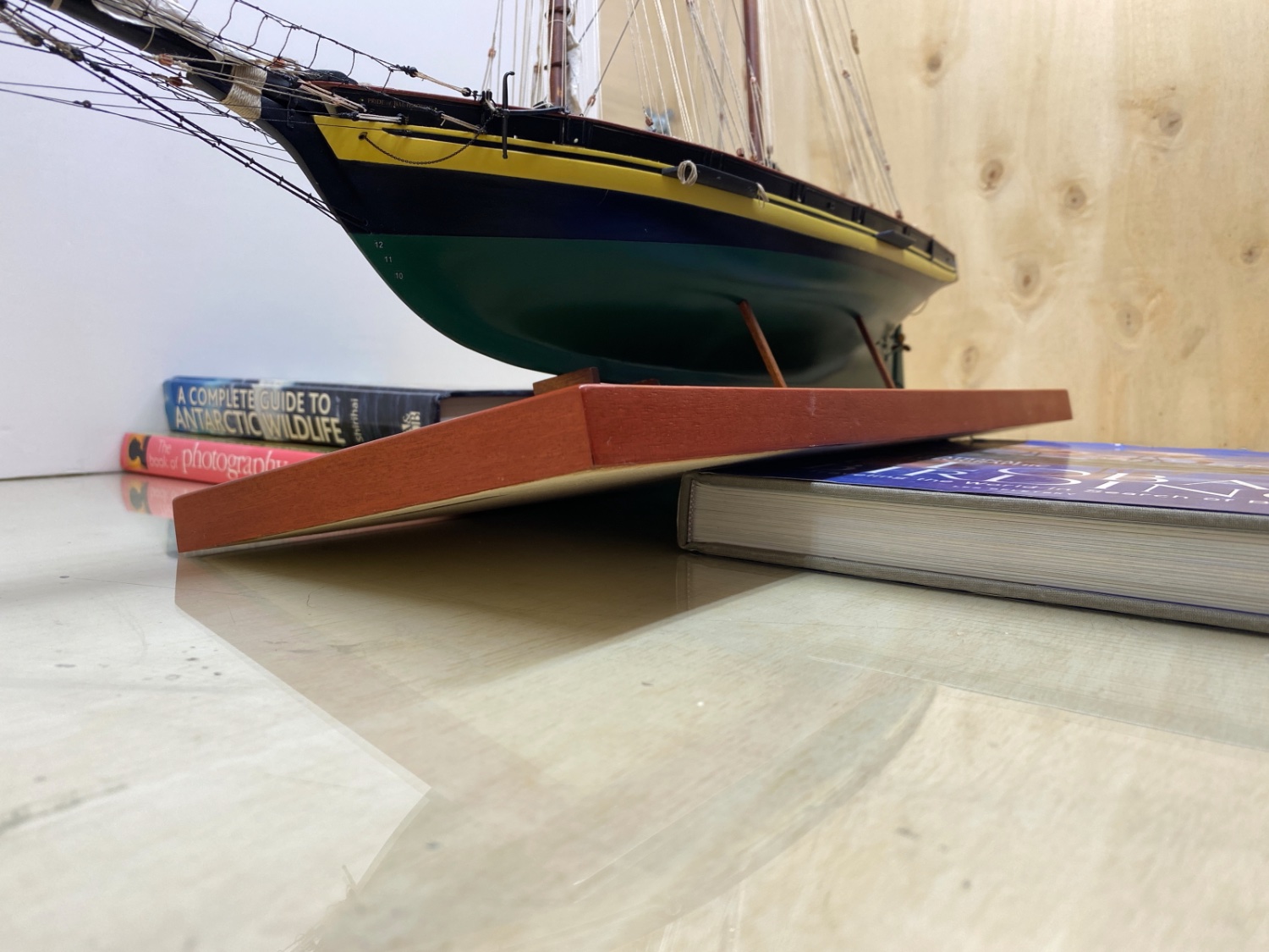
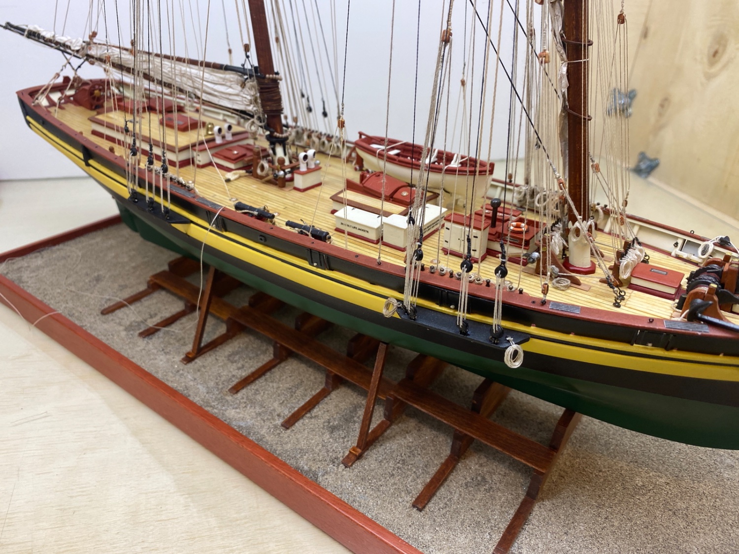
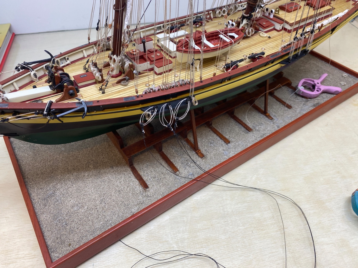
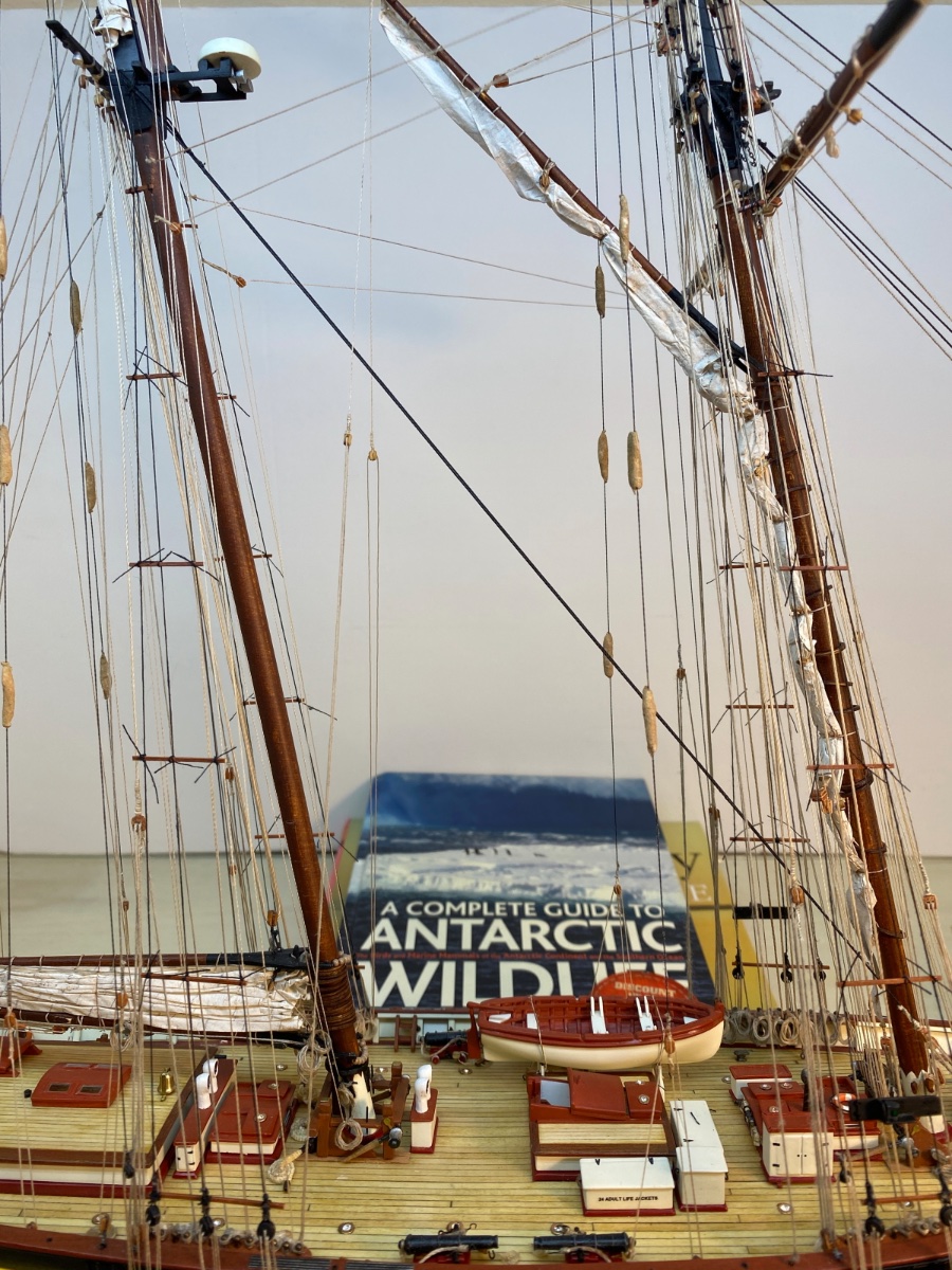
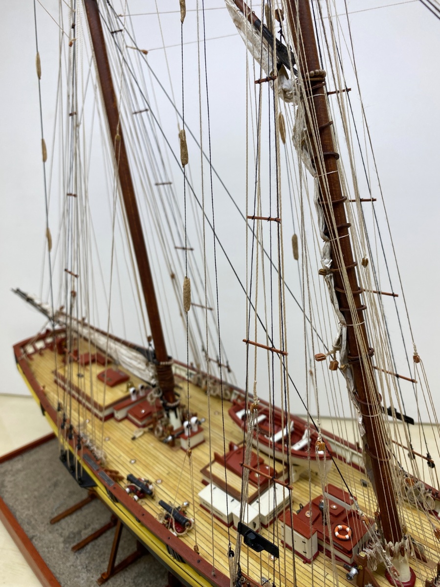
The next step was the rigging of the prepared lines. In order to elevate the chain plate platforms to horizontal eye level and to visualize the hull area where chain plates were to be glued, I used some hardcover books as seen in the photos below..

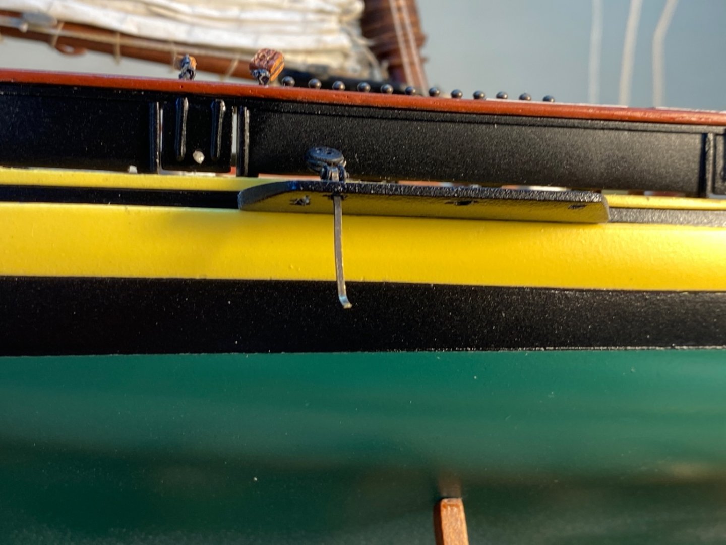
I started with the Topmast Stay lines. Lower deadeyes and chain plates were glued to place by applying gel CA glue to the holes on the chain plate platforms first. Then the chain plate was glued to hull. Here it was impossible to drill a hole and place a nail because of the scale. Liquid gap filling CA glue was then applied to the hole which deadeye sits on and to the chain plate-hull point.
The installation of the Topmast stays was done in the order of port-fore, port-main, starboard-main and starboard- fore. Here are some photos of this step.
Port fore
Port fore and main
Starboard fore
Starboard main
Starboard fore Topmast stay chain plate
Port fore Topmast stay chain plate

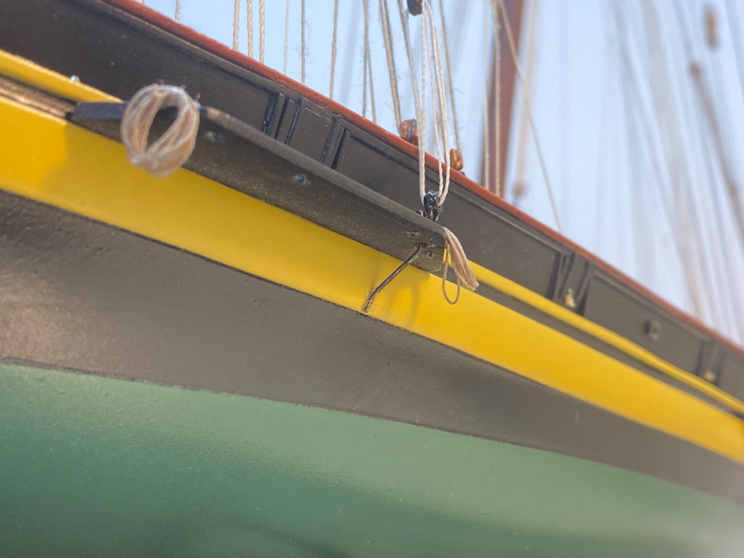
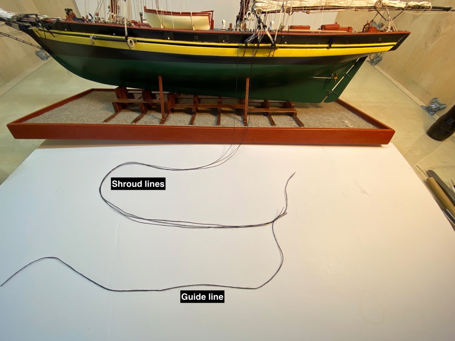
Then I started with the shrouds. I did port main shrouds first. After installing all three deadeye and chains I tied a guide line at a necessary distance to the three shroud lines. The guide was used when looping the shroud lines around the mast head.
Port aft lanyard systems glued in place.
Guide line knotted.

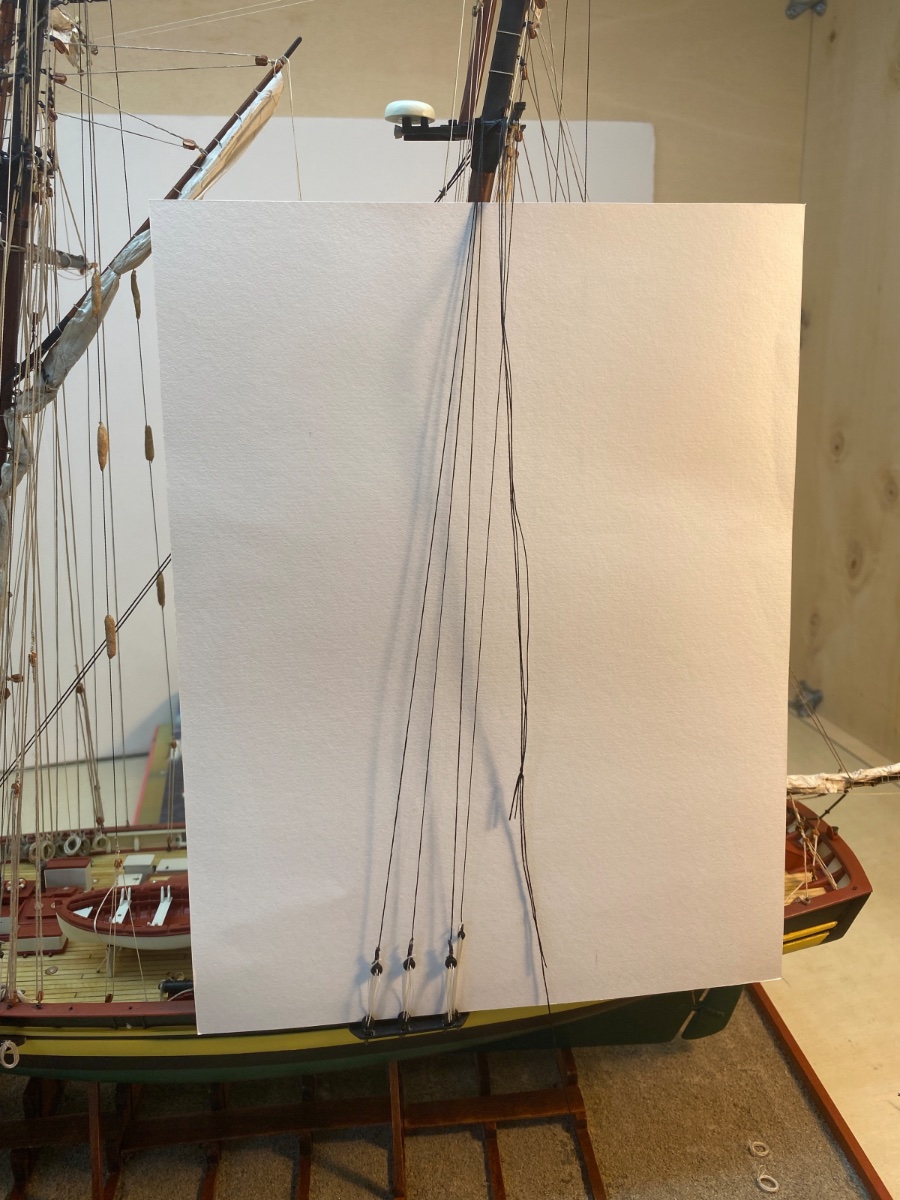
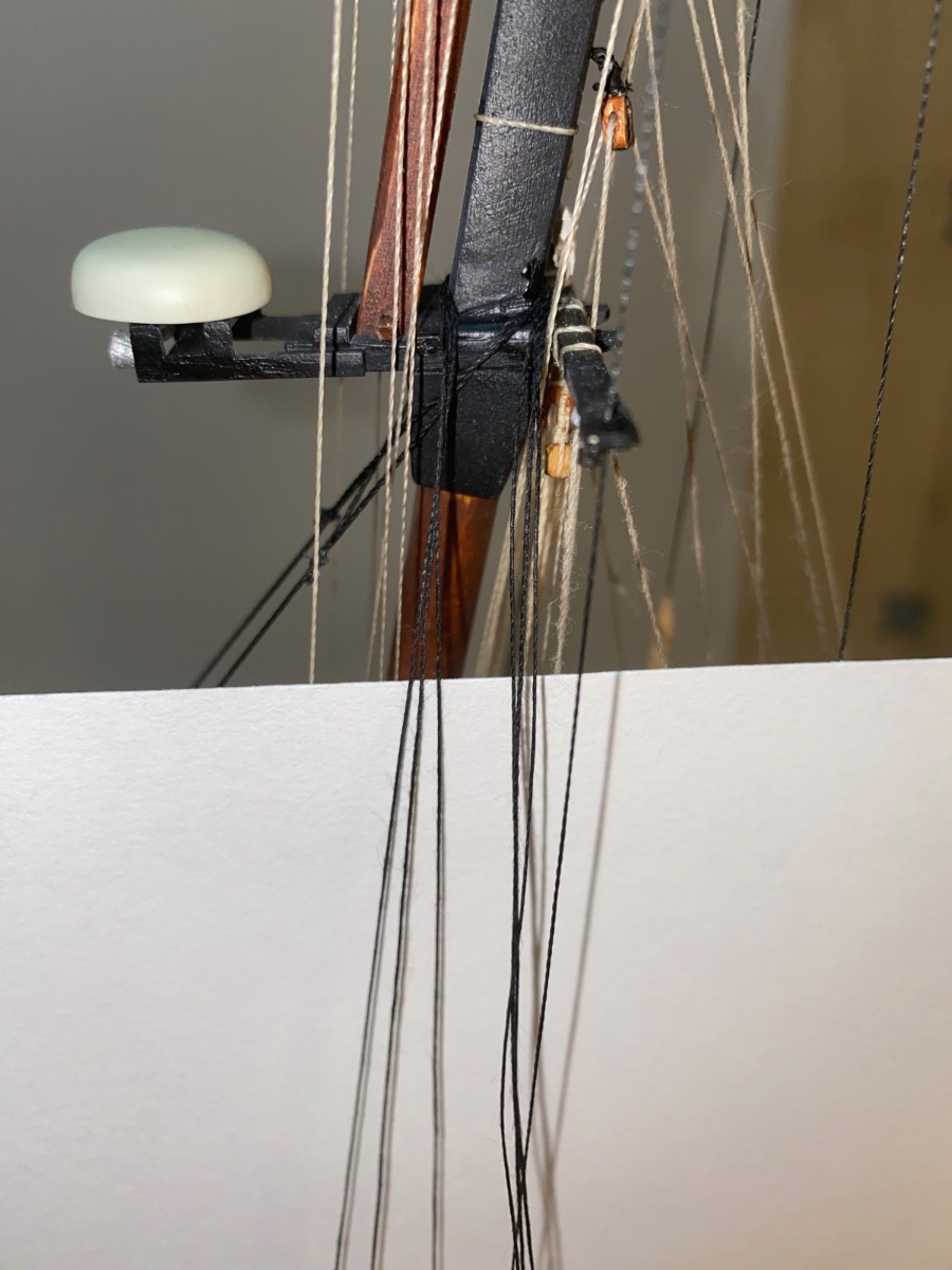
Guide line looped around mast head and pulled down.

Shroud lines around the mast head

Ascending and descending shroud lines were tied with an overhead knot using a smaller size black thread after checking the shroud lines were as taut as necessary.

Then the descending three lines were cut as close to the knot as possible.
Port aft shrouds were installed.

Port aft shrouds deadeyes, lanyards, chain plates and chain plate platform.

Starboard side fore and main shrouds were done in the next step
 Port fore shrouds were the last ones done.

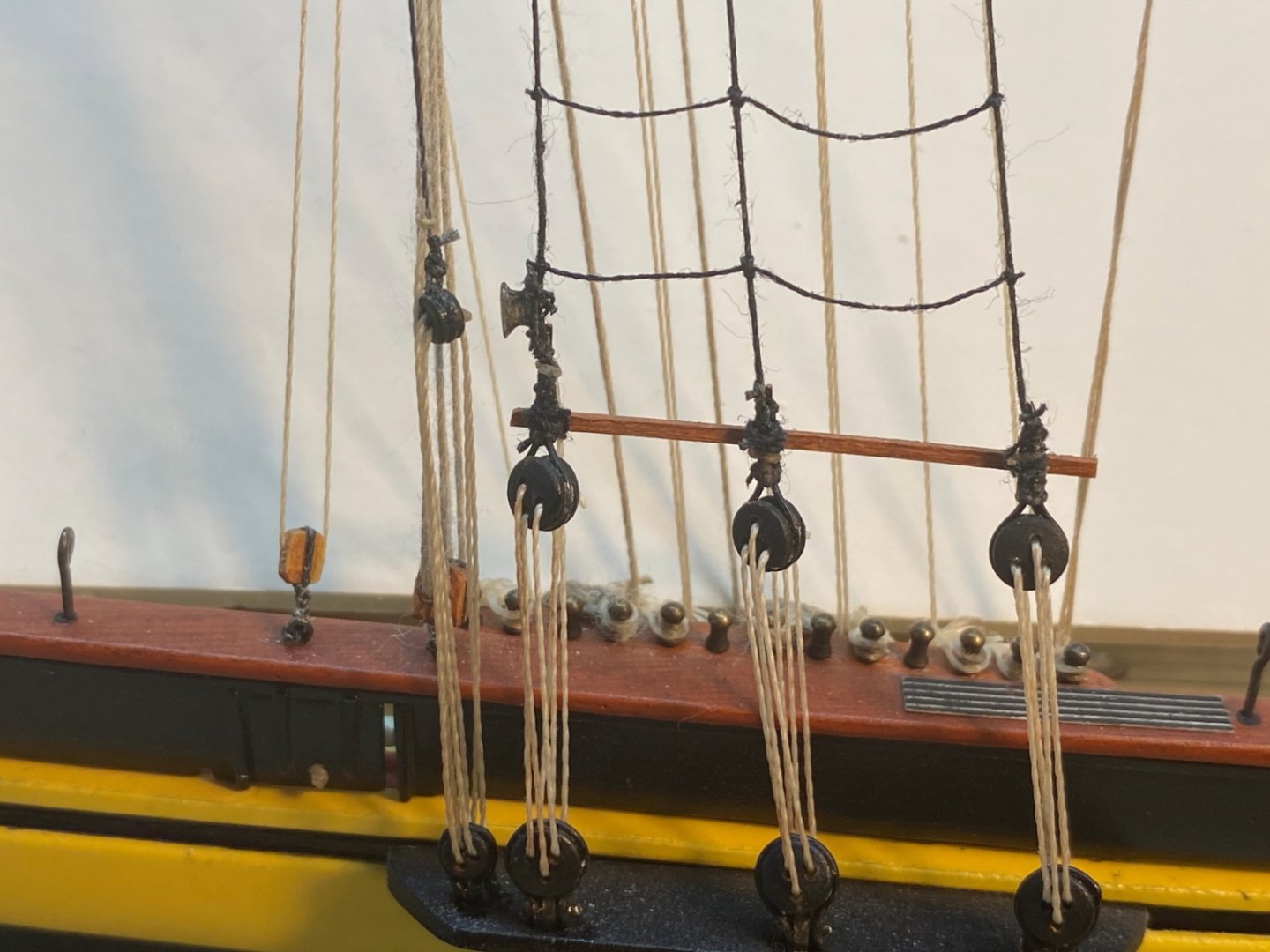
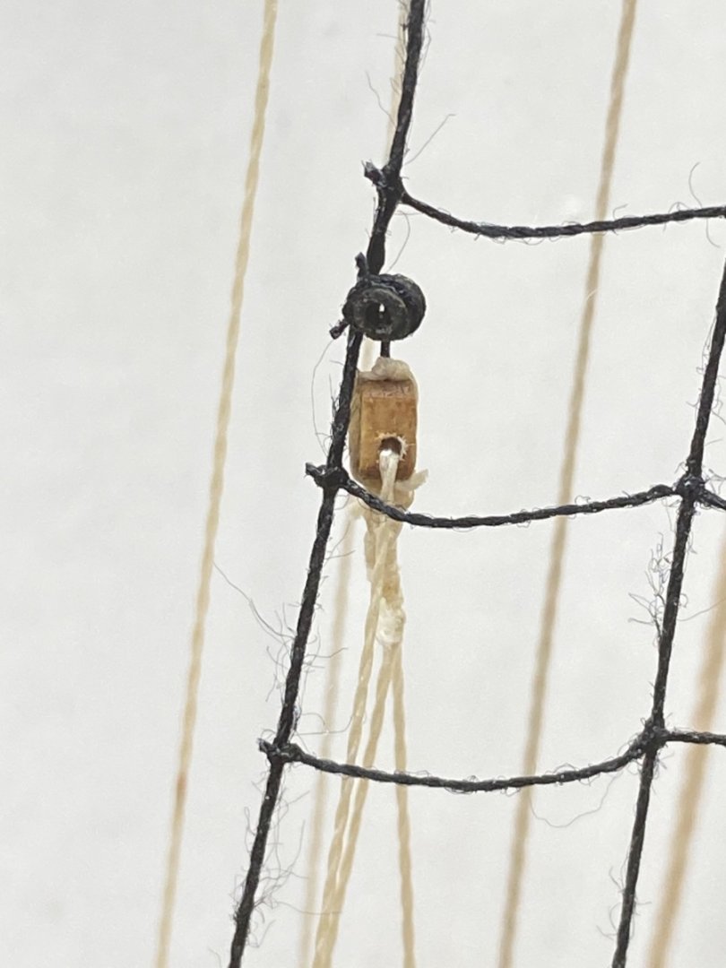
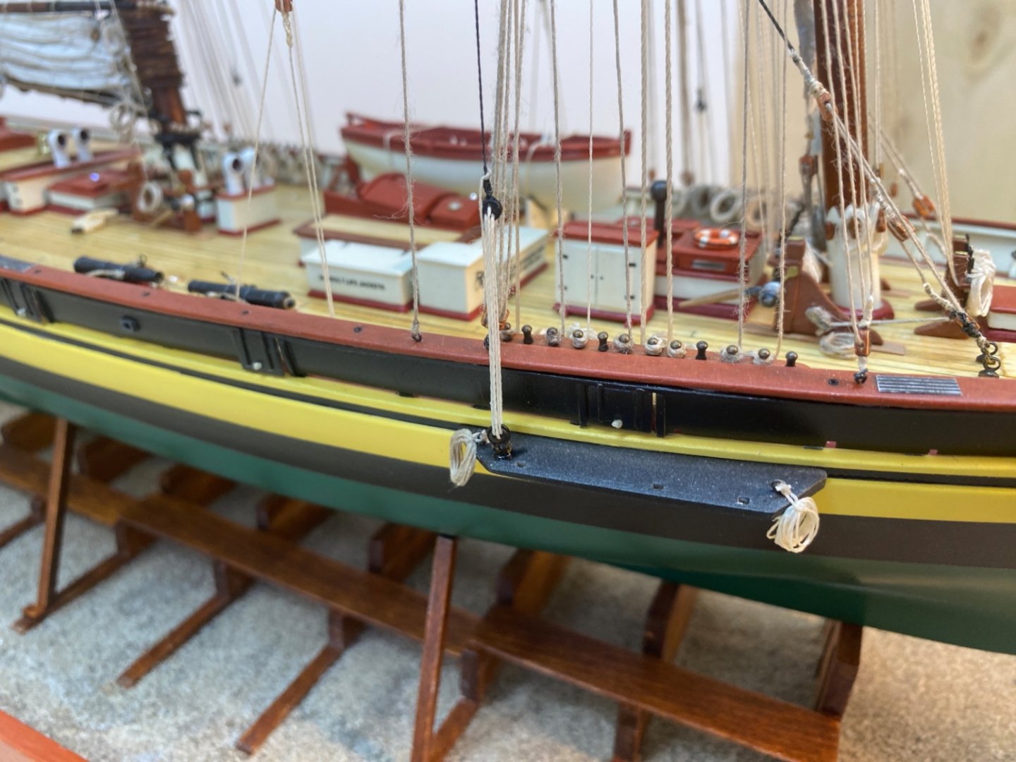
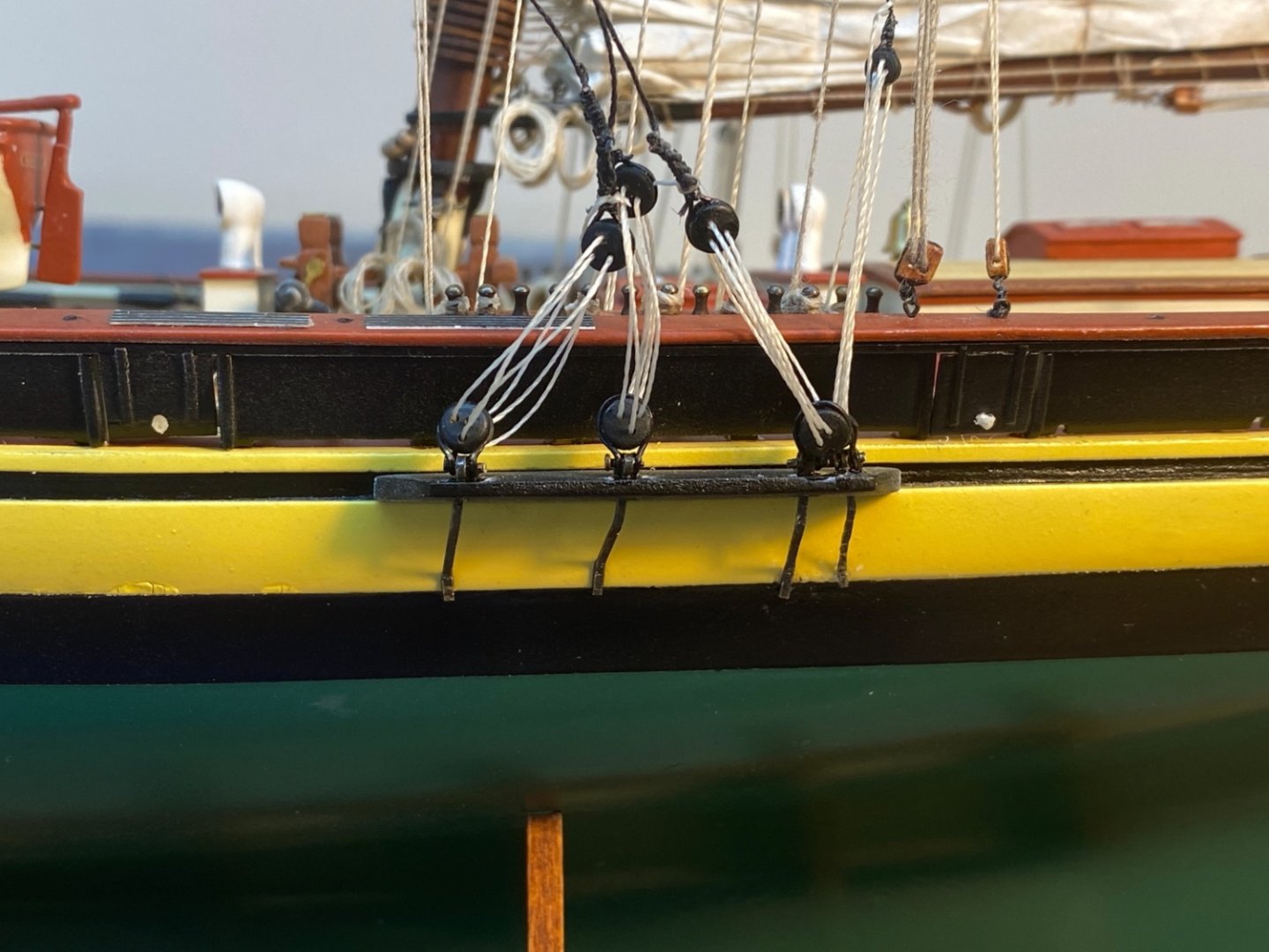
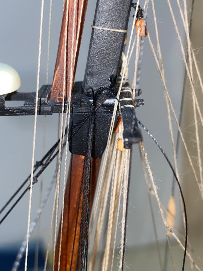
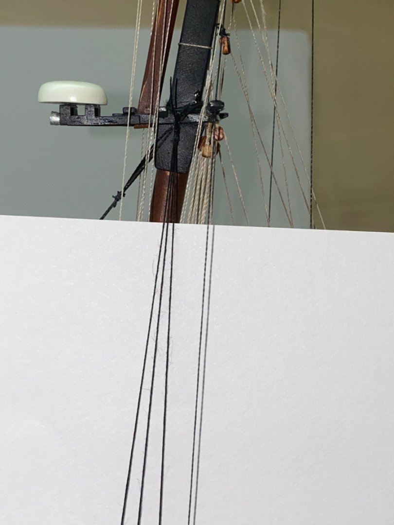
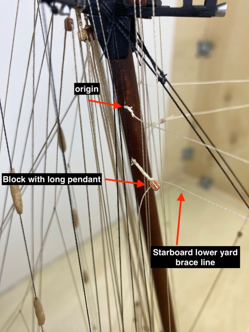
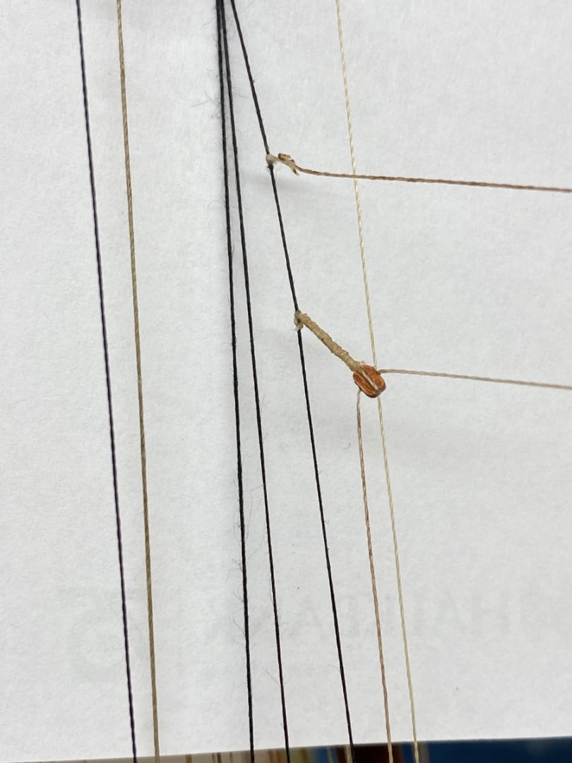
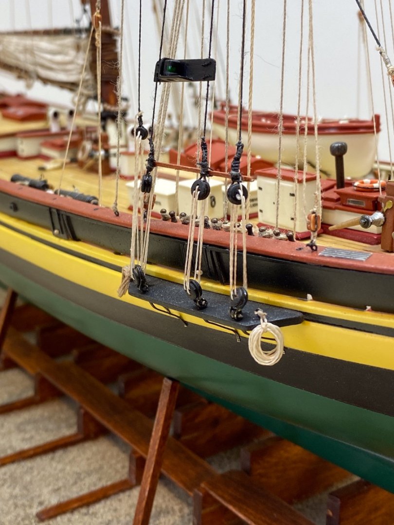
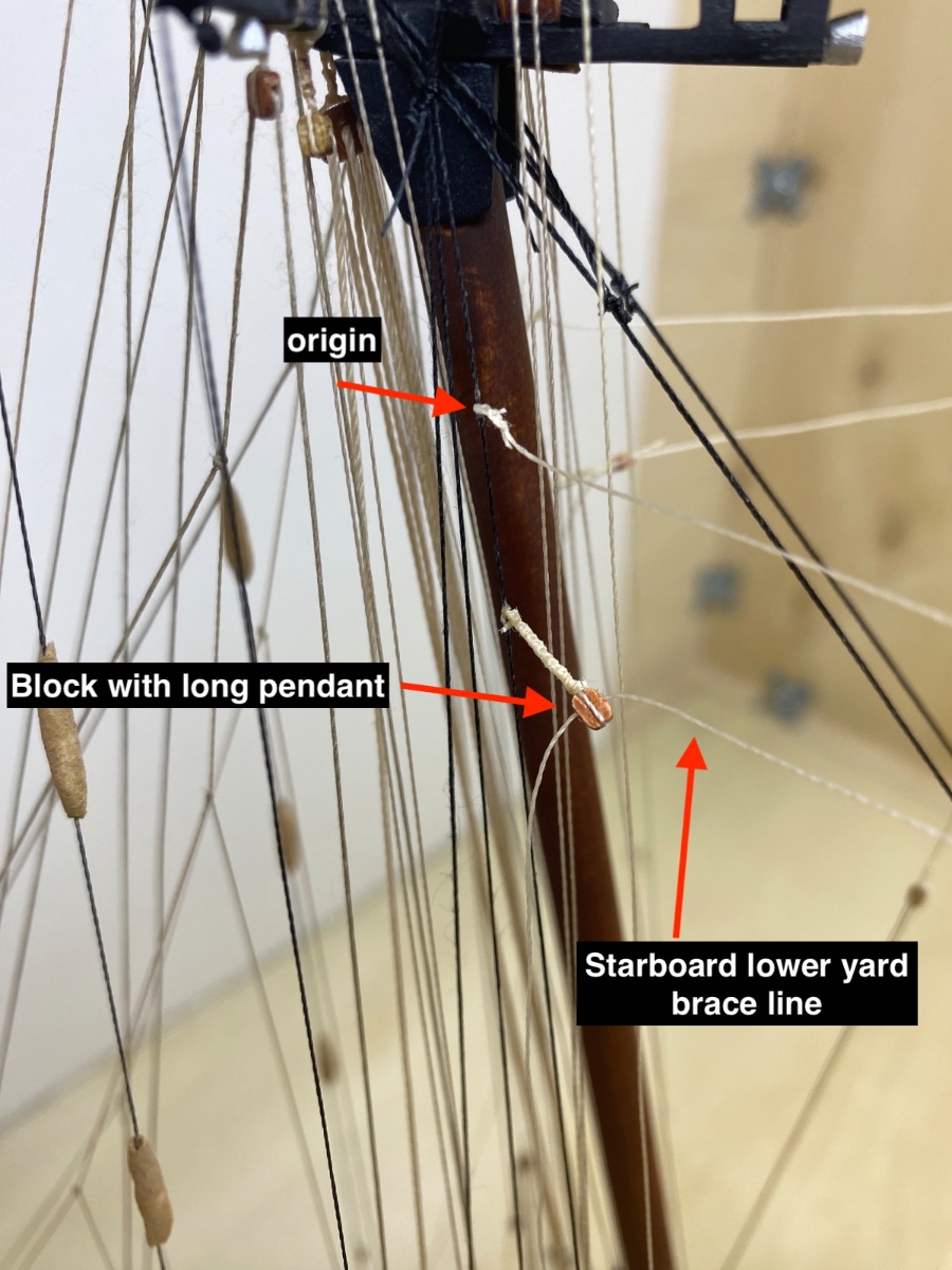
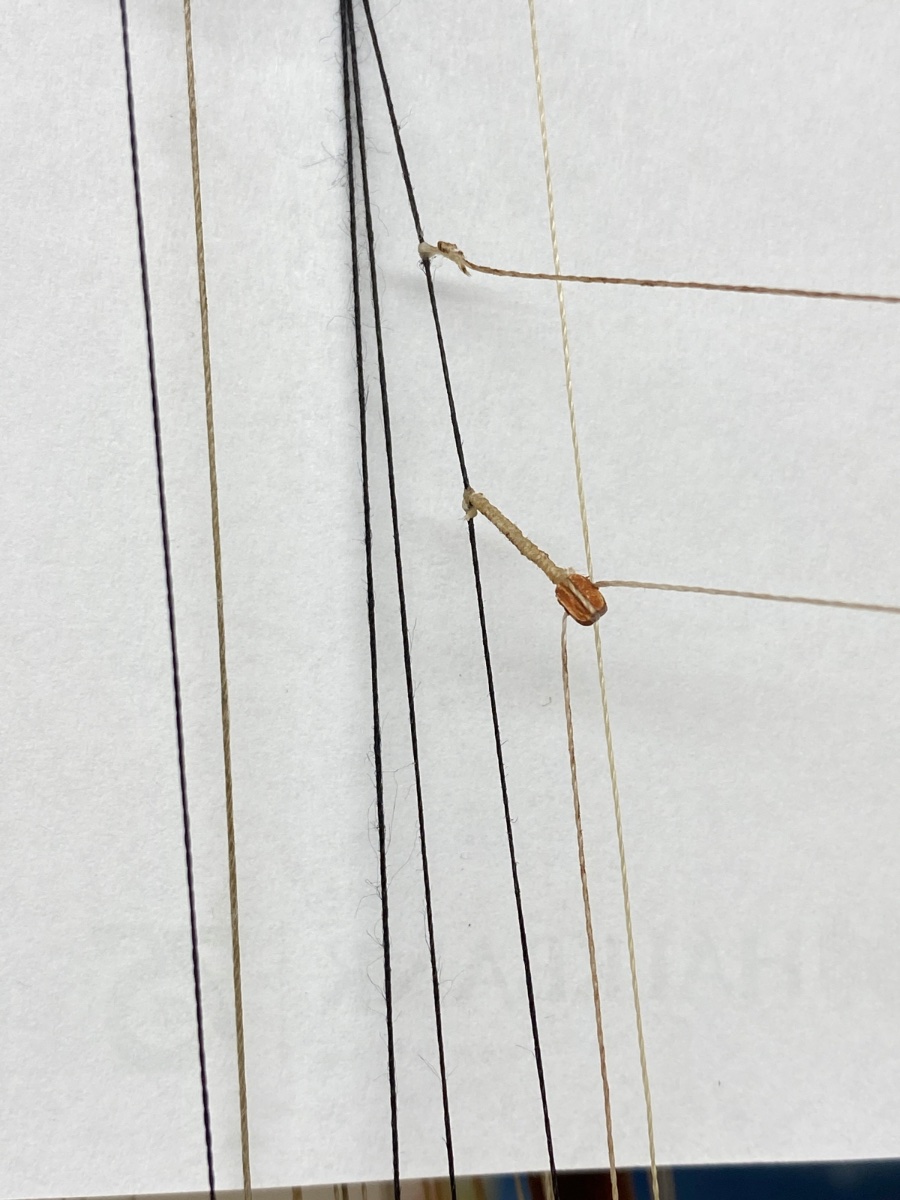
The rigging line and blocks for fore lower yard braces were now can be installed as the shroud lines were done. This line originates from the fore shroud line of the aft shrouds, reeves through its same named block at the arms of fore lower yard and comes back to the shroud line and reeves this time another block with a long pendant and belays at the pin rails. Here you see the starboard side brace rigging line at origin and reeving through the block with a long pendant.
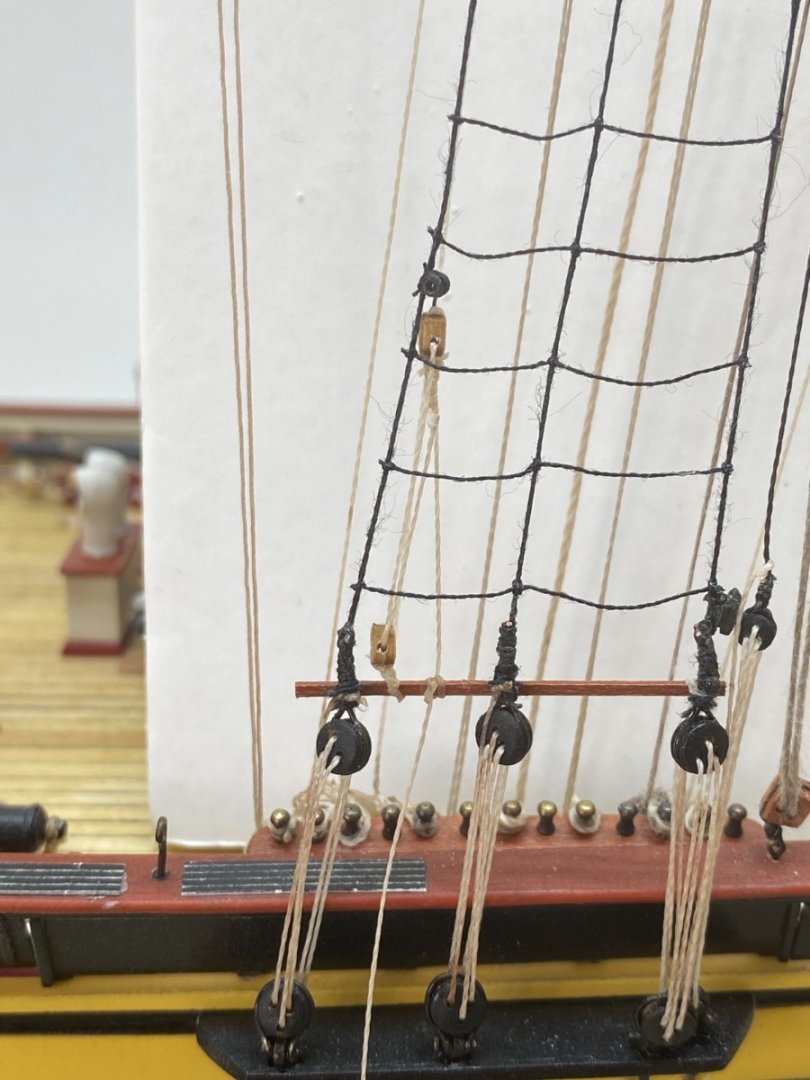
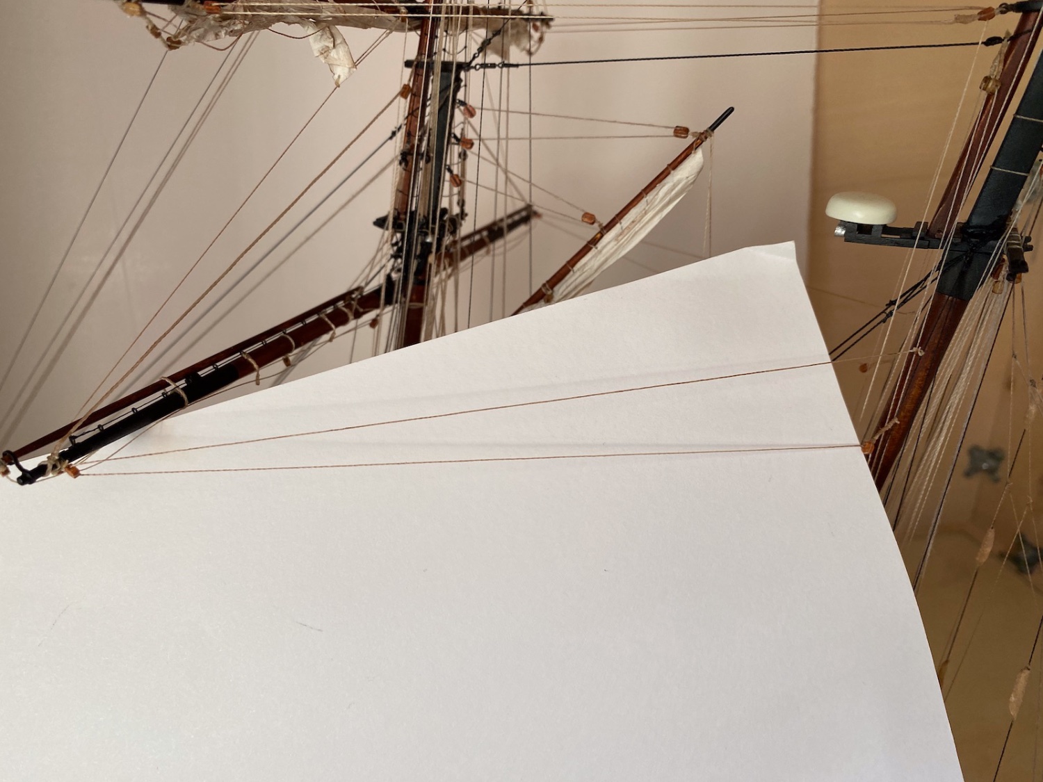
Port side fore lower yard brace rigging

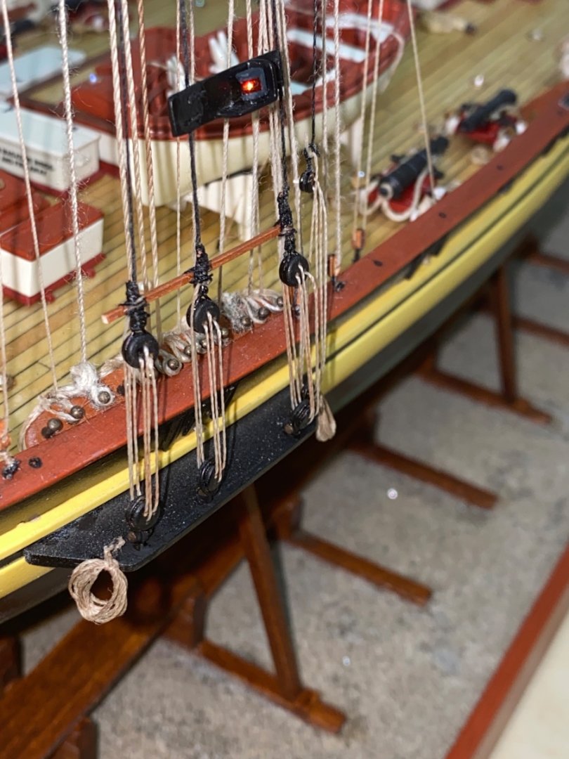
As the shrouds were finished the next step was the ratlines. However running port (red) and starboard (green) lights and wood sheer poles of the shrouds must first be installed. After the positions of the running lights and wood sheer poles right above the upper deadeyes were set, they were installed. Set up photo of this step

Starboard fore
Port fore
Starboard main
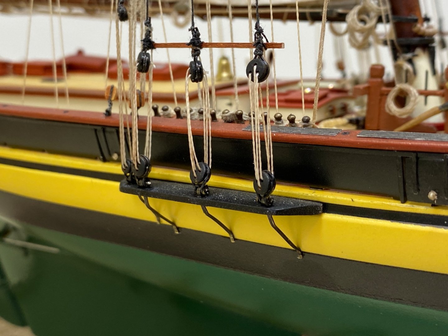
Port main
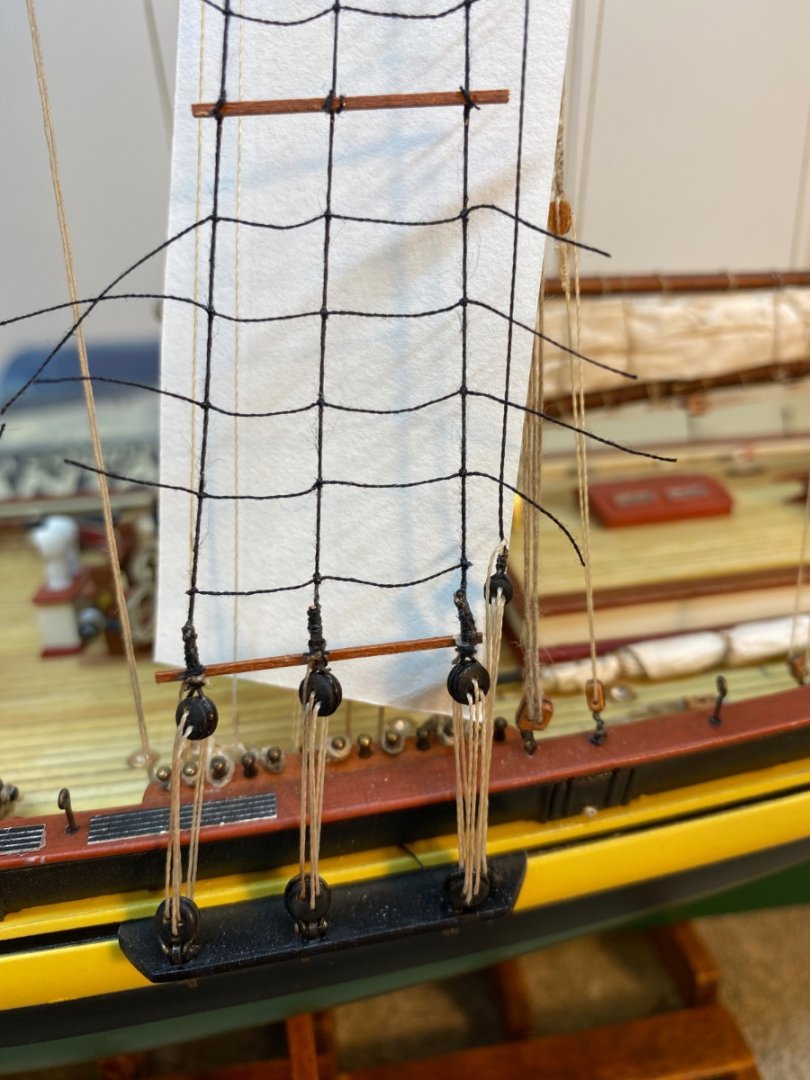
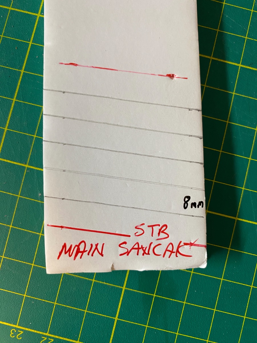
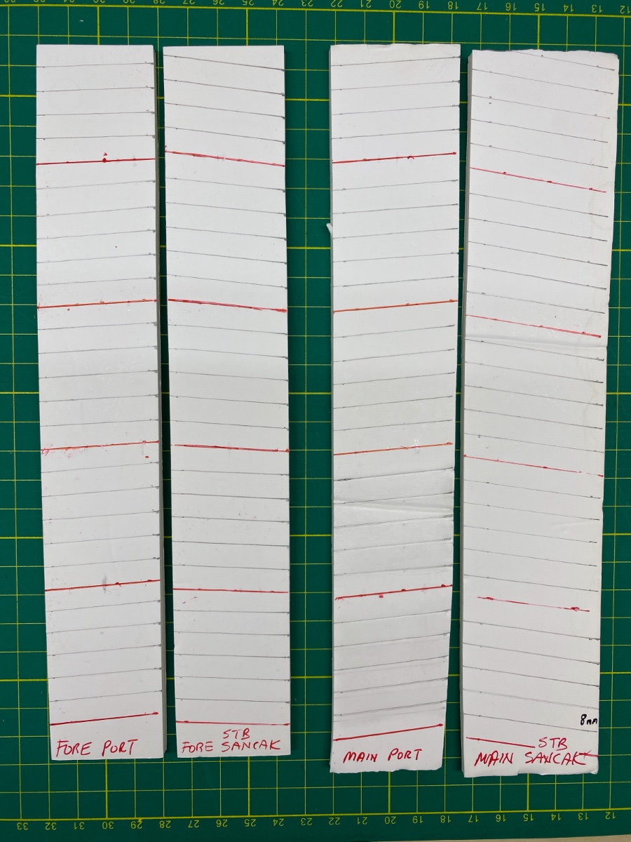
I continued with the wood battens of the shrouds. I prepared a marked jig from a thick cardboard indicating the level of the battens for each one of the four shrouds and used them when installing the battens. The battens must be parallel to the deck or to the base platform.
Starboard main batten jig
Port main battens

Port fore battens
Photos after the wood battens


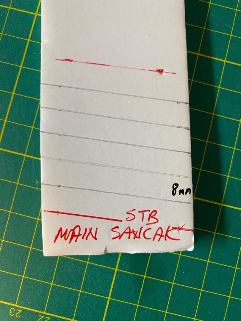
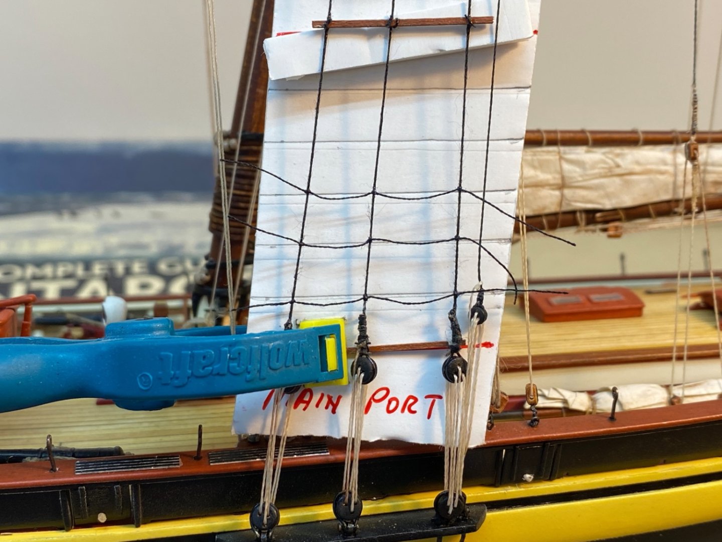
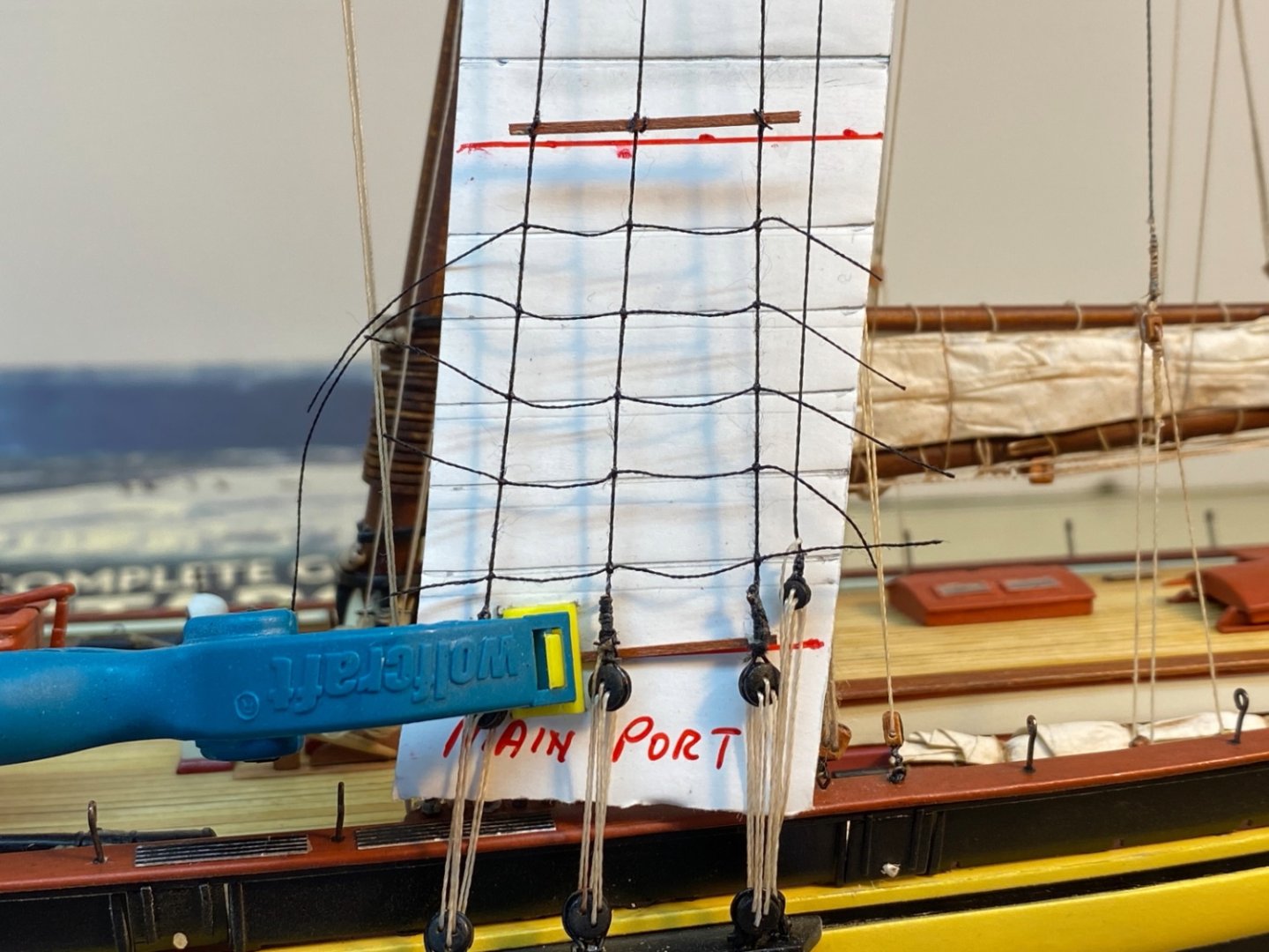
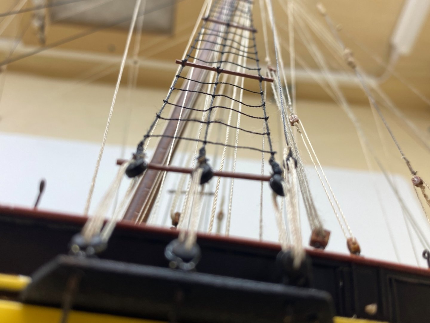
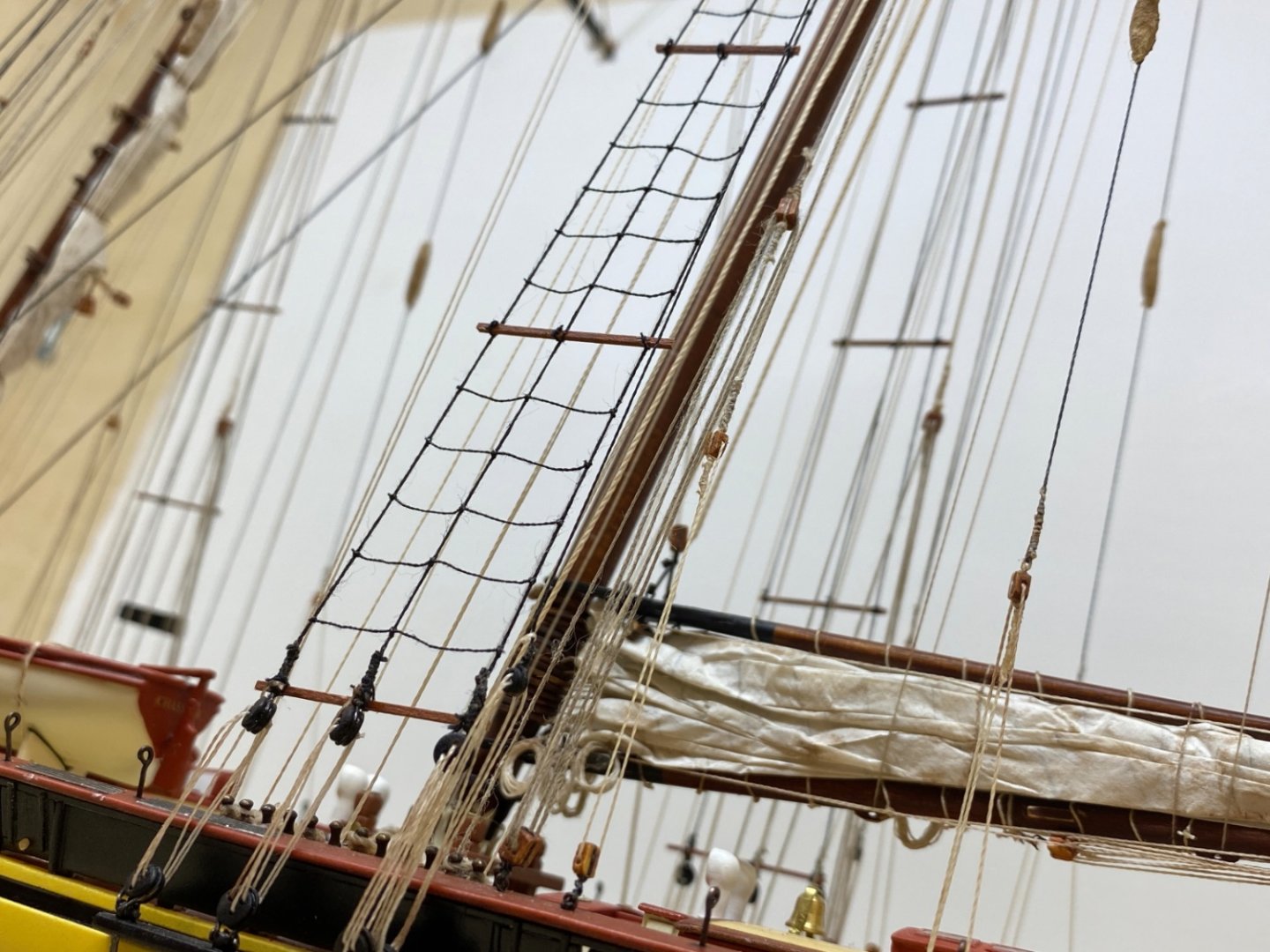
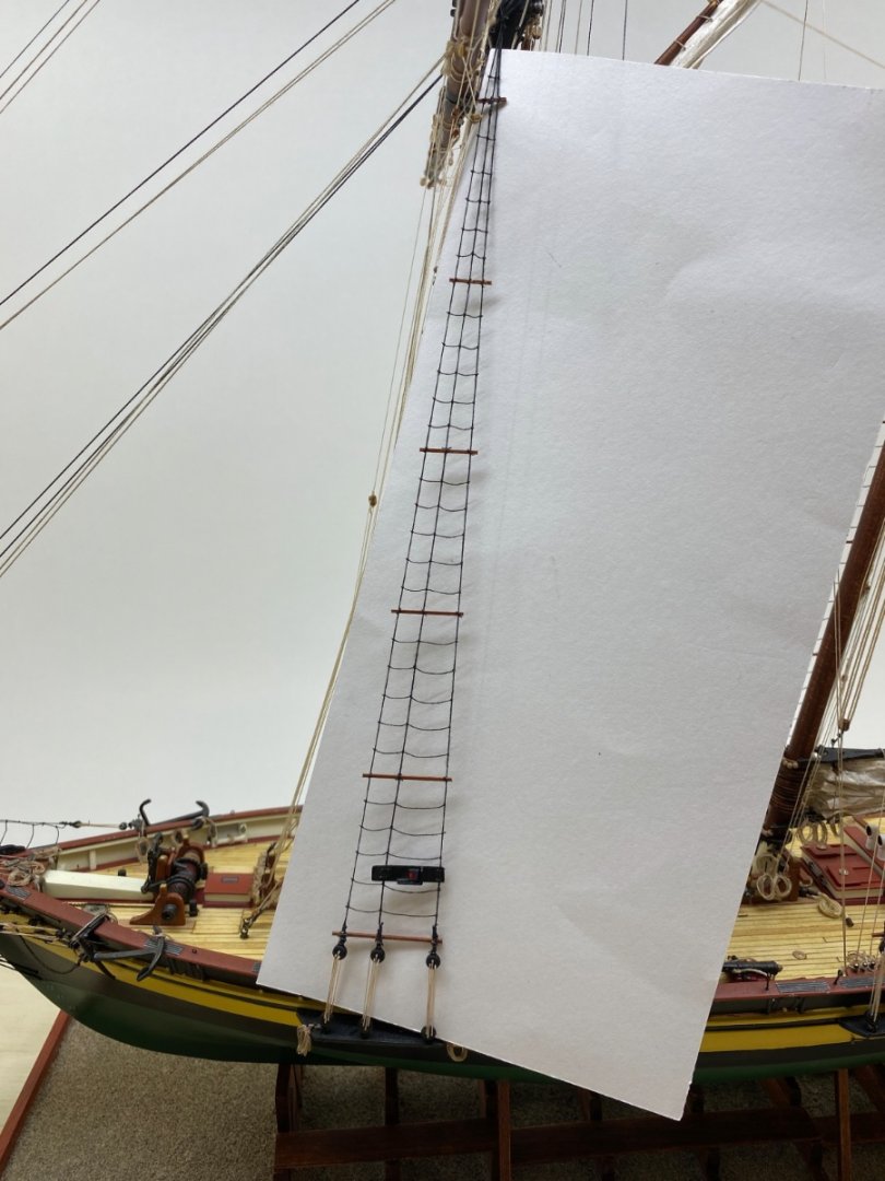
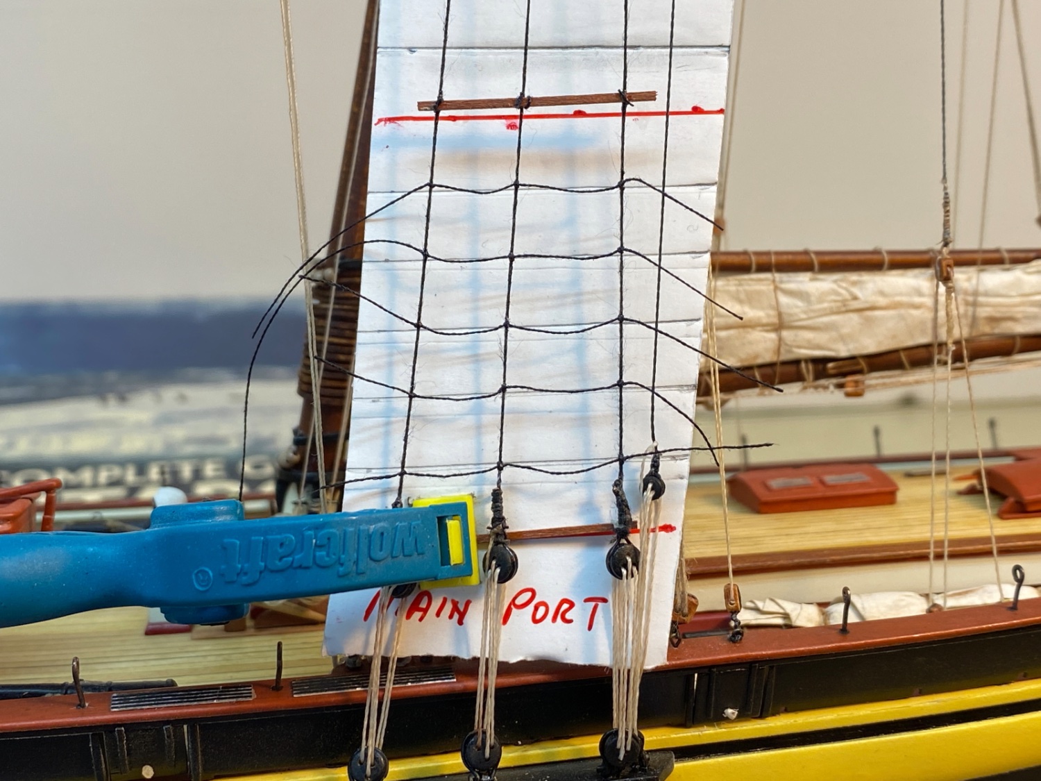
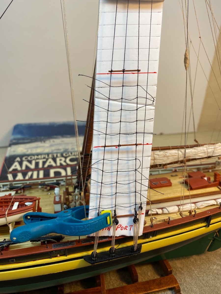
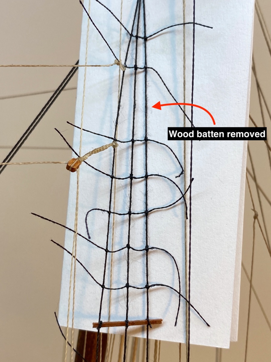
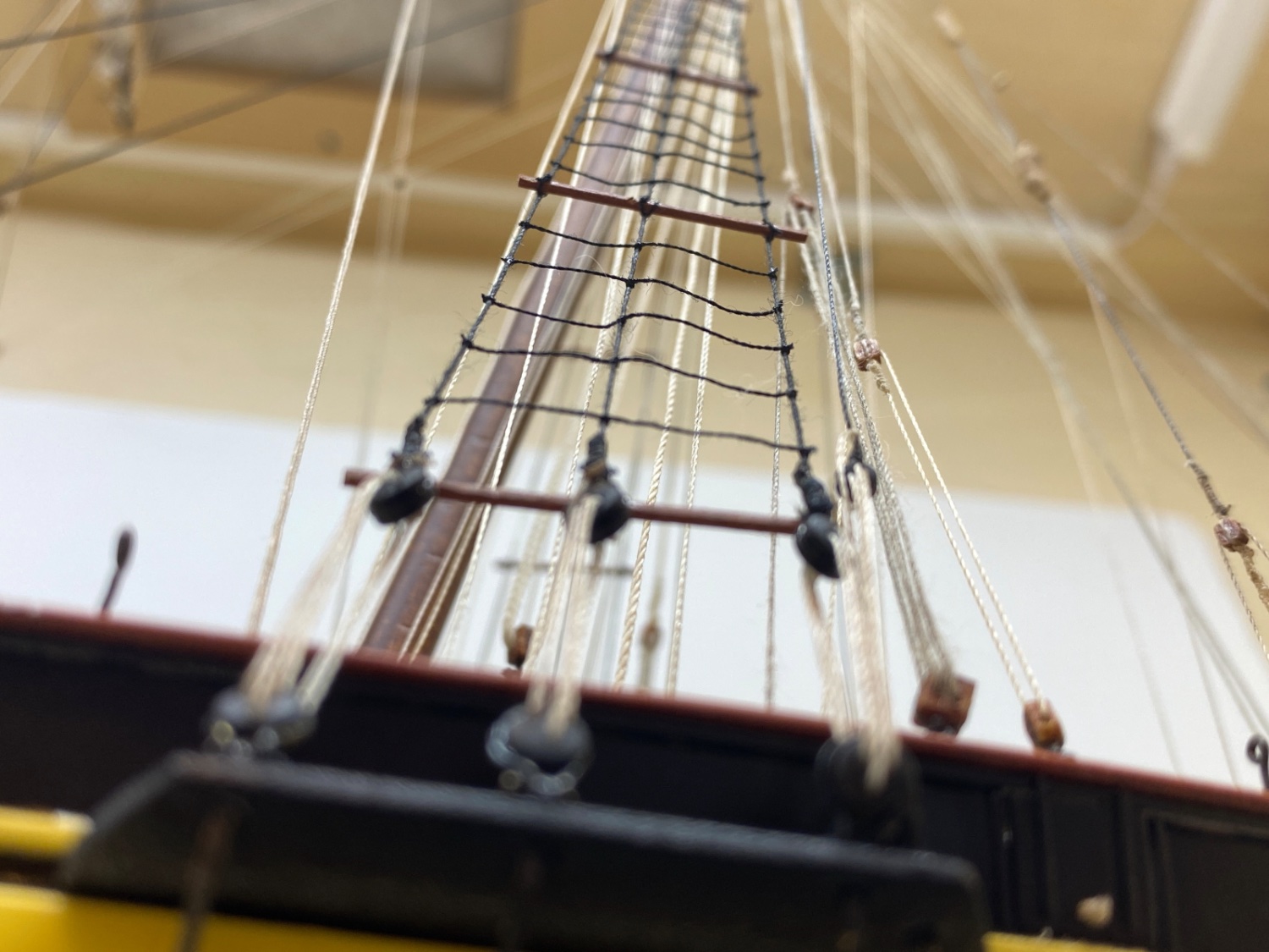
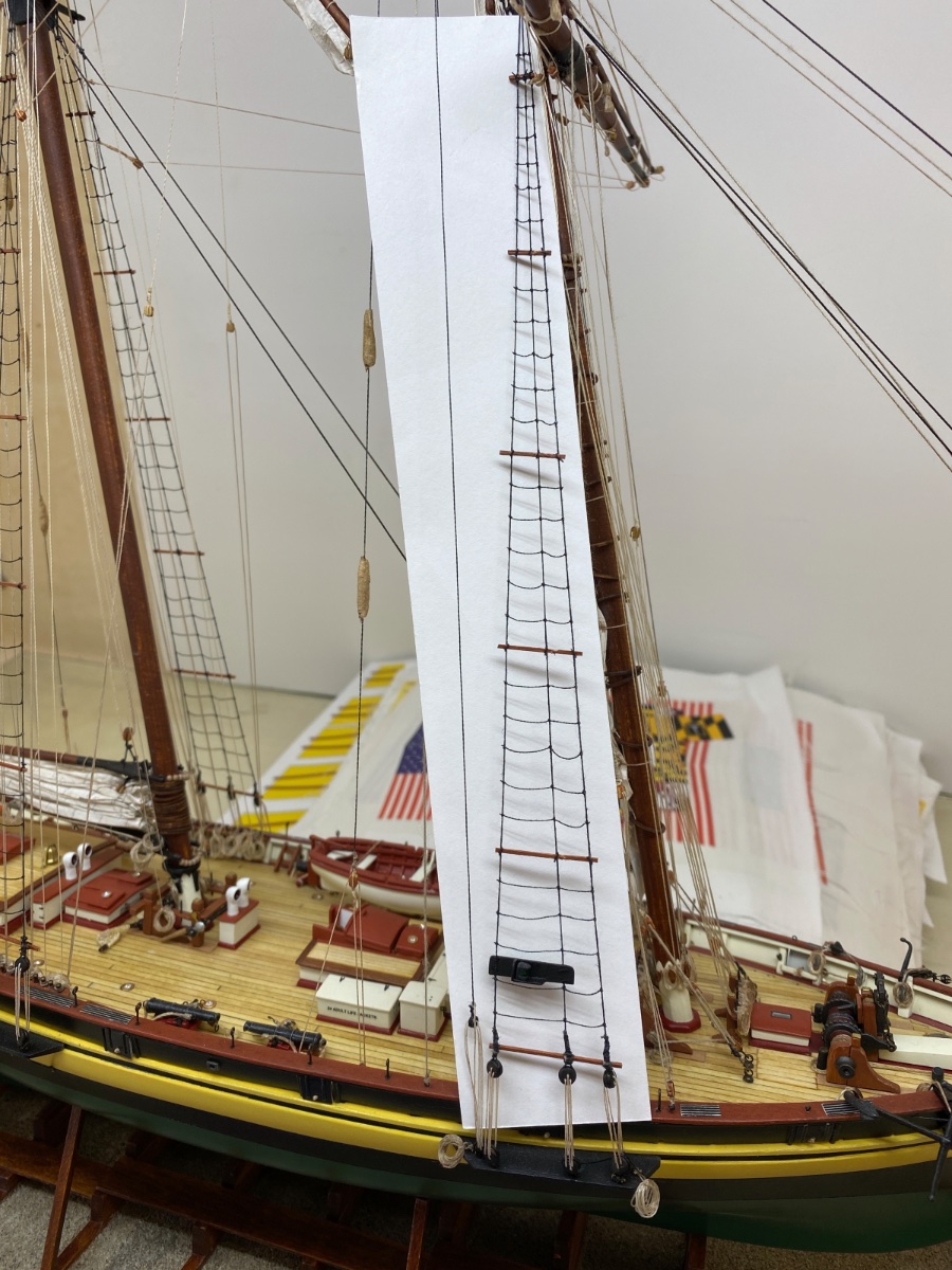
Finally it was time to tie the ratlines. The jigs used for wood battens were used again but with the guide lines for rat lines were drawn this time. As you can see the distance between rat lines was 8 mm.

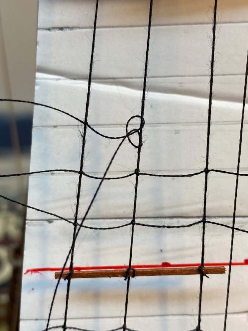
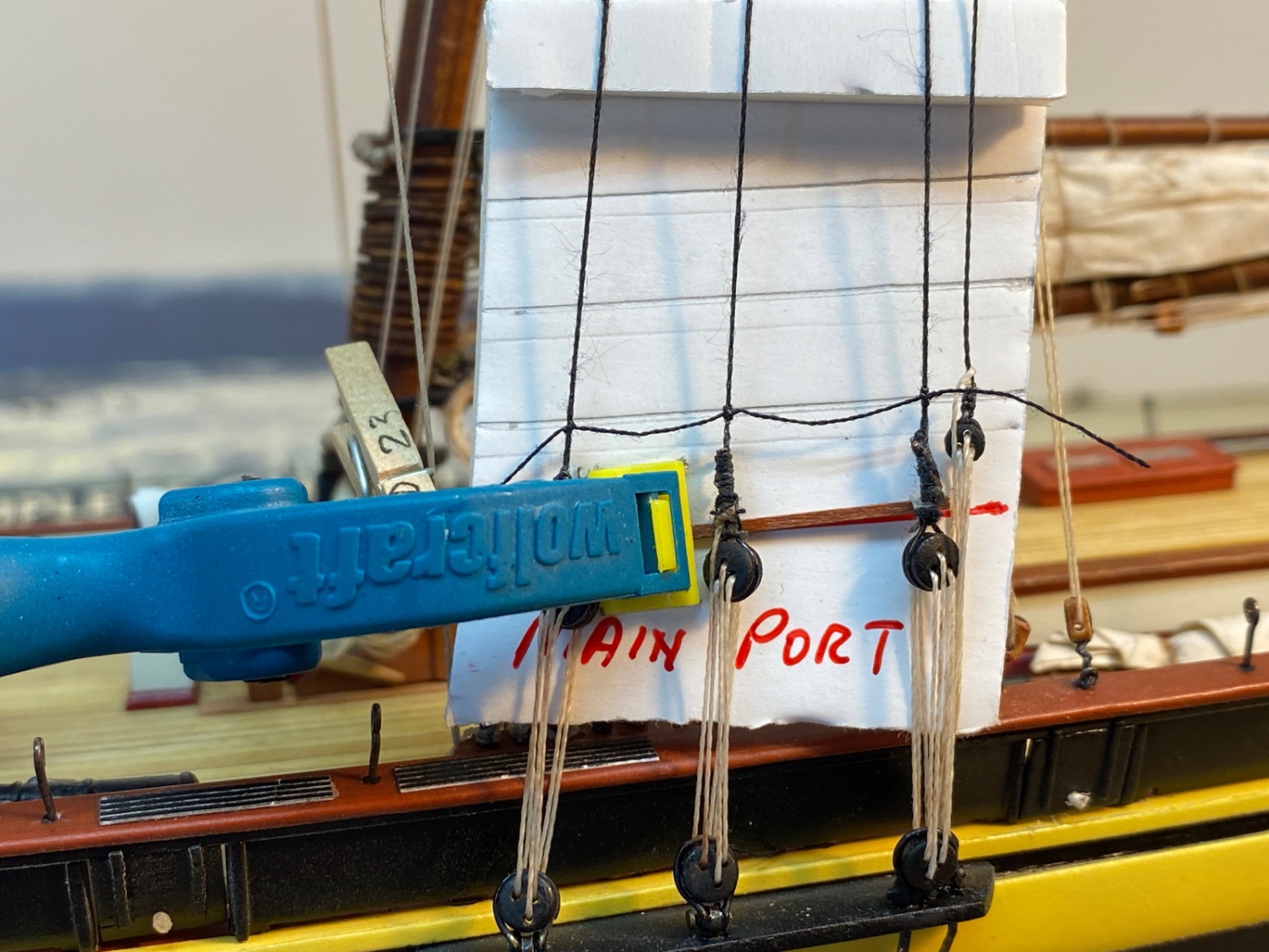
I started tying the first knot to the left shroud line as I look. The first knot is a simple overhead knot. The knot was fixed with a touch of CA glue. The second and third knots are clove hitches. Ca glue WAS NOT applied until the desired position of the ratline was set. Then 3rd knot was fixed with CA glue. Middle knot was left untouched. Ca glue was applied to some rebel! ratlines in order to put them in position and order!.
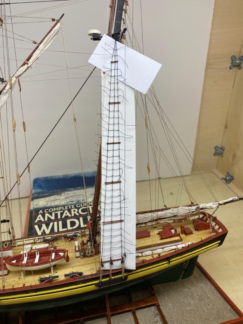
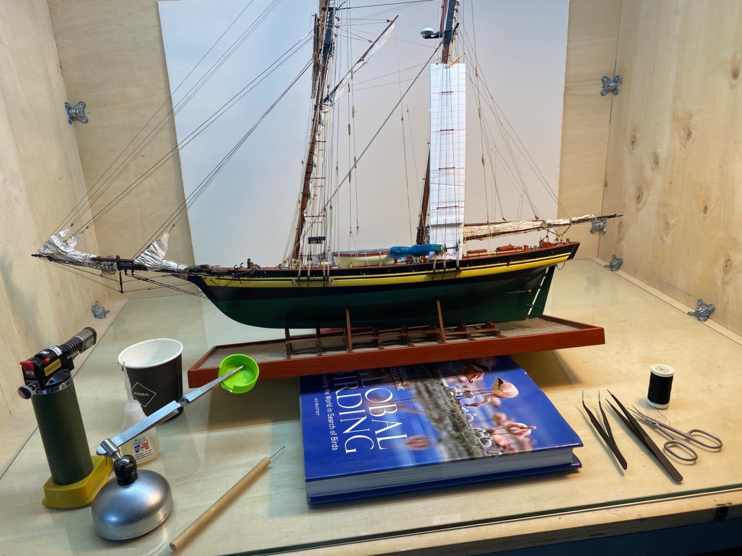
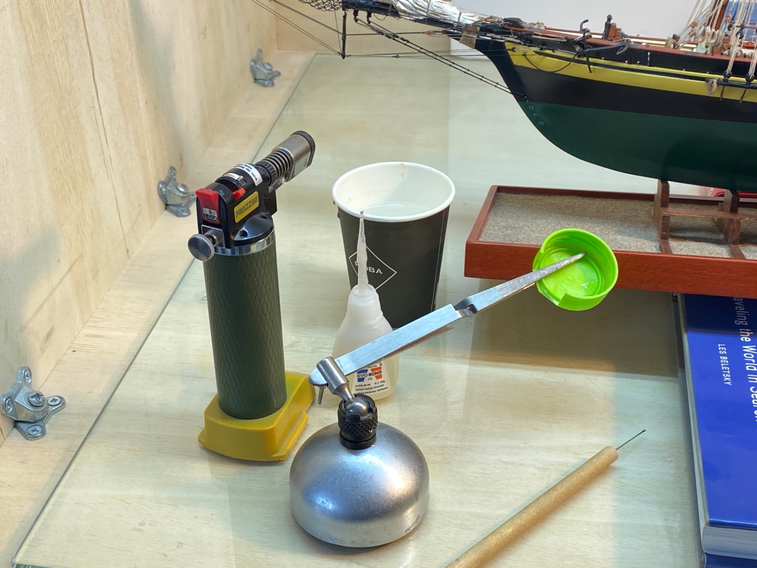
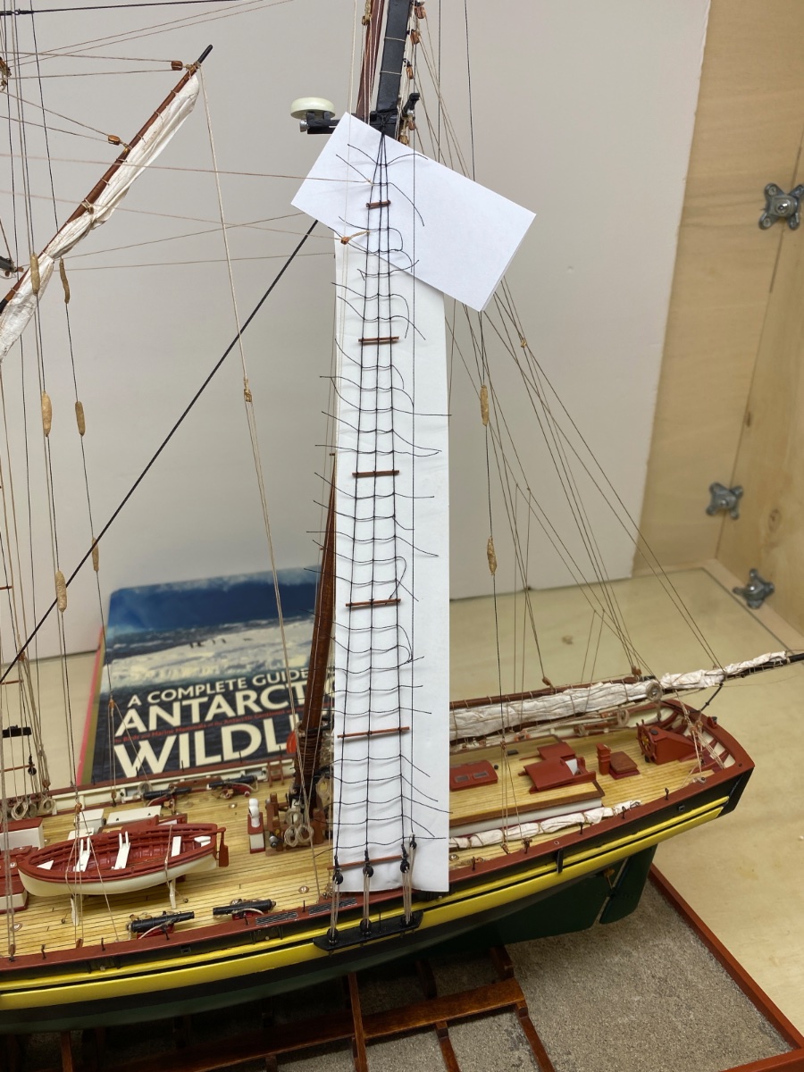
Here is the setup for the ratlines.The jig for port main shroud ratlines was placed.

Proxxon flame torch was used to clean the tip of the glue applicator. Glue was poured in the green bottle cap in small amounts and the water in the paper cup was used to cool the glue applicator tip.

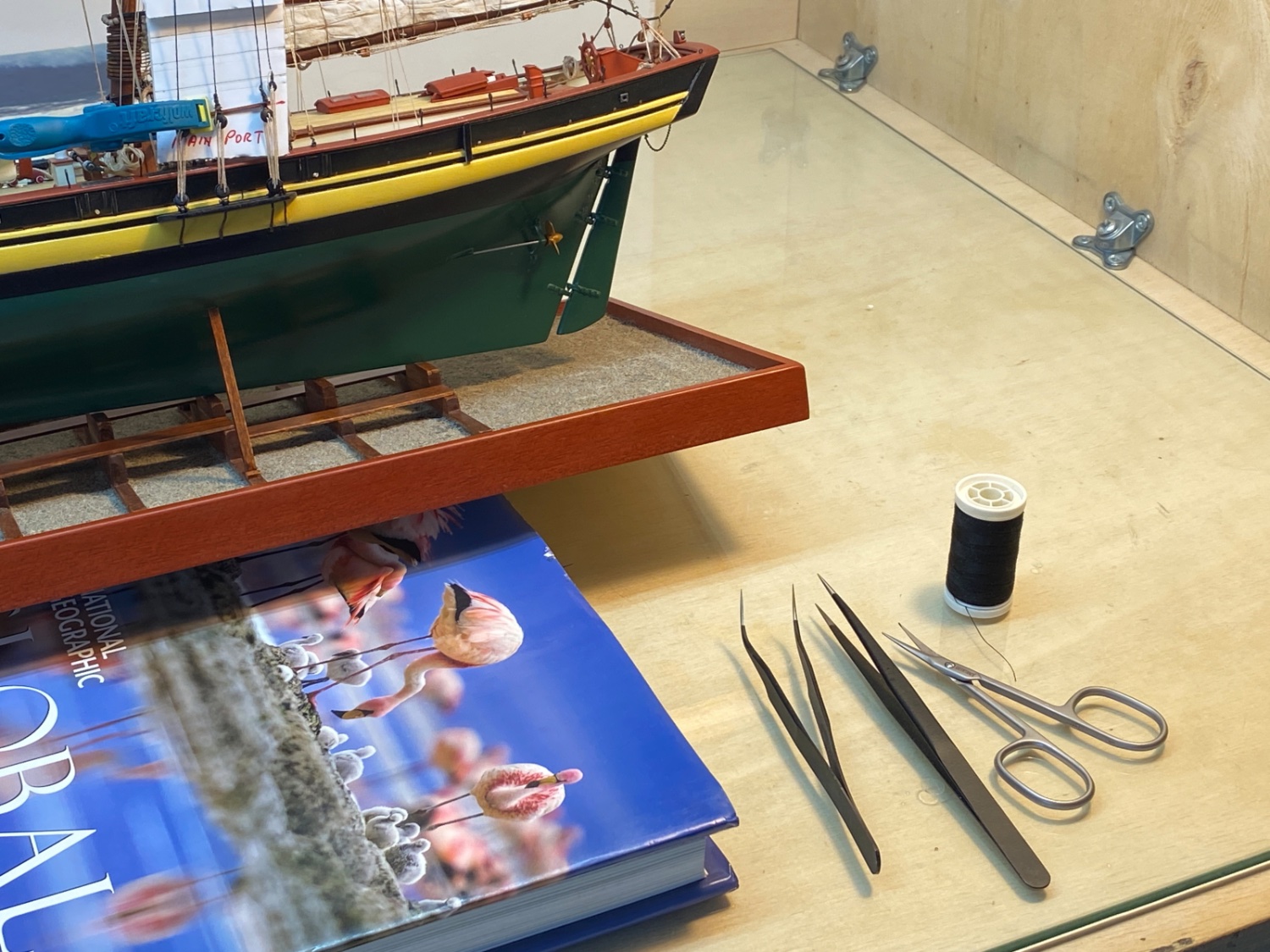
Black thread, fine tip tweezers and fine tip scissors. Although not shown in the picture, bees wax was also used. The ratline job was done under magnifying glasses.

The rat lines were done in port main, starboard main, starboard fore and port fore order.
Here are the photos of port main shroud ratlines.

Clove hitch 8 formation

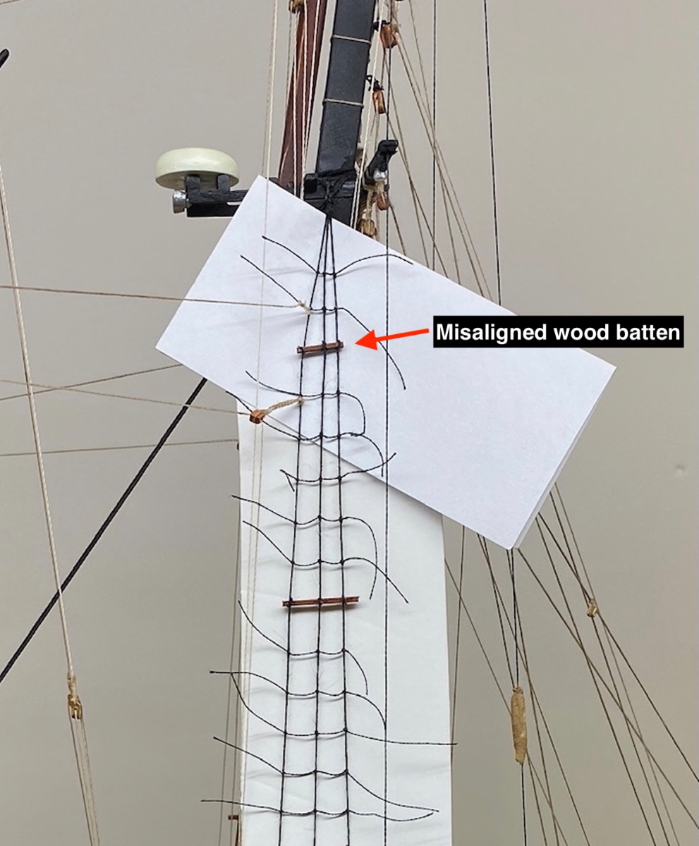
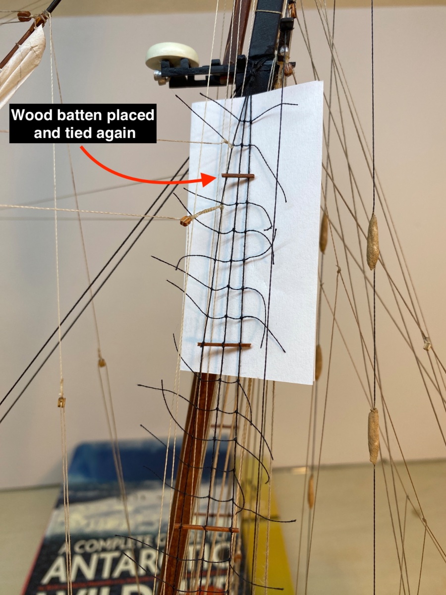
During the process a misaligned wood batten was removed and placed again.

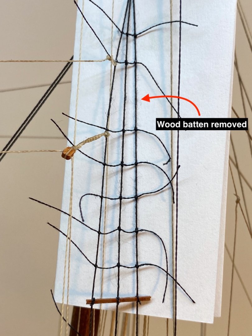

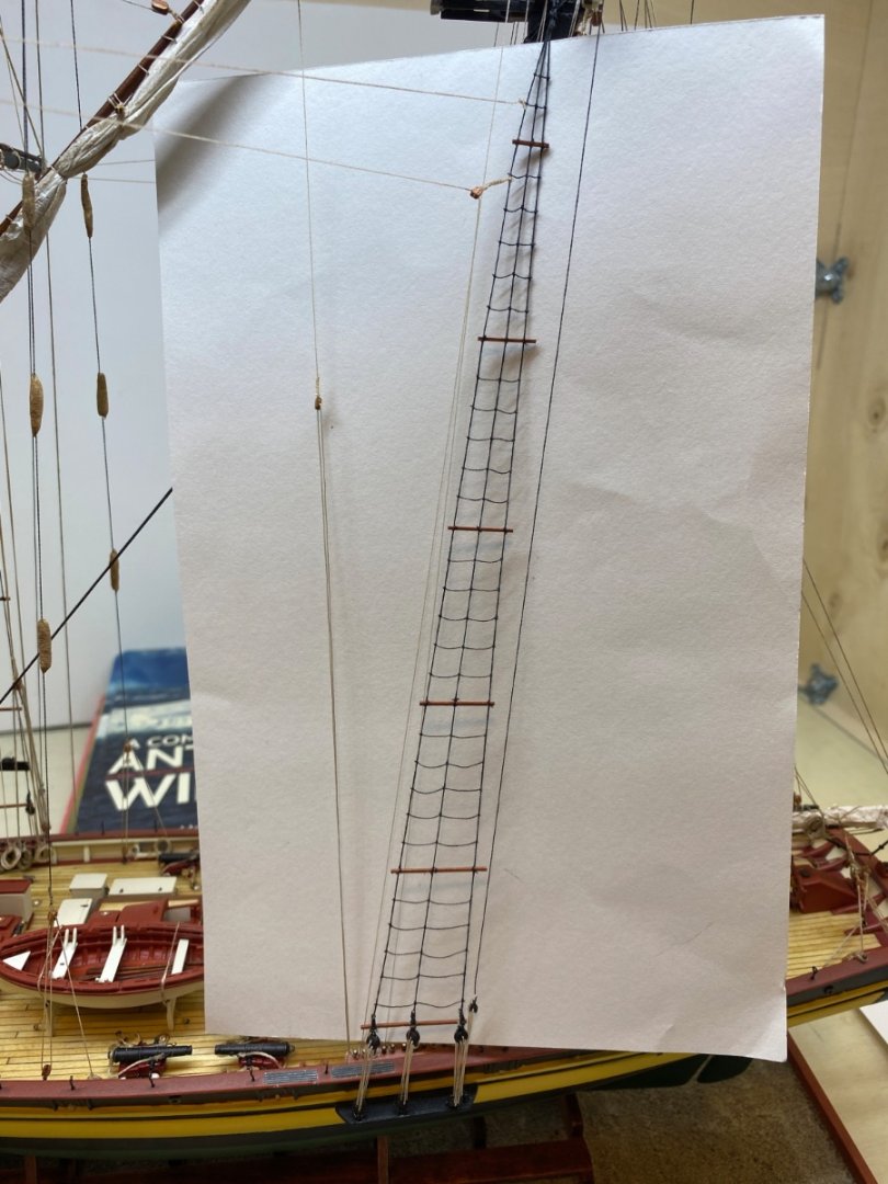
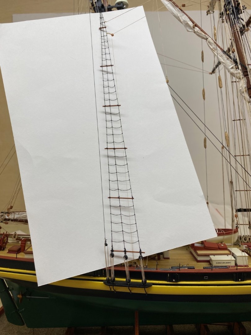
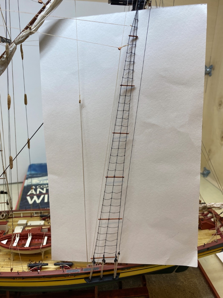
After the ratlines of port main shroud were done, the jig was removed. Lower ratlines looked good on a white background .
Then the excess thread of the 1st and 3 rd knots were cut as close to the knots as possible with a sharp and pointed tip scissor.
 Using mobile phone cameras enables to take unusual angled photos.
The other shroud ratlines were done in the same manner.
Starboard main shroud ratlines
Starboard fore shroud ratlines

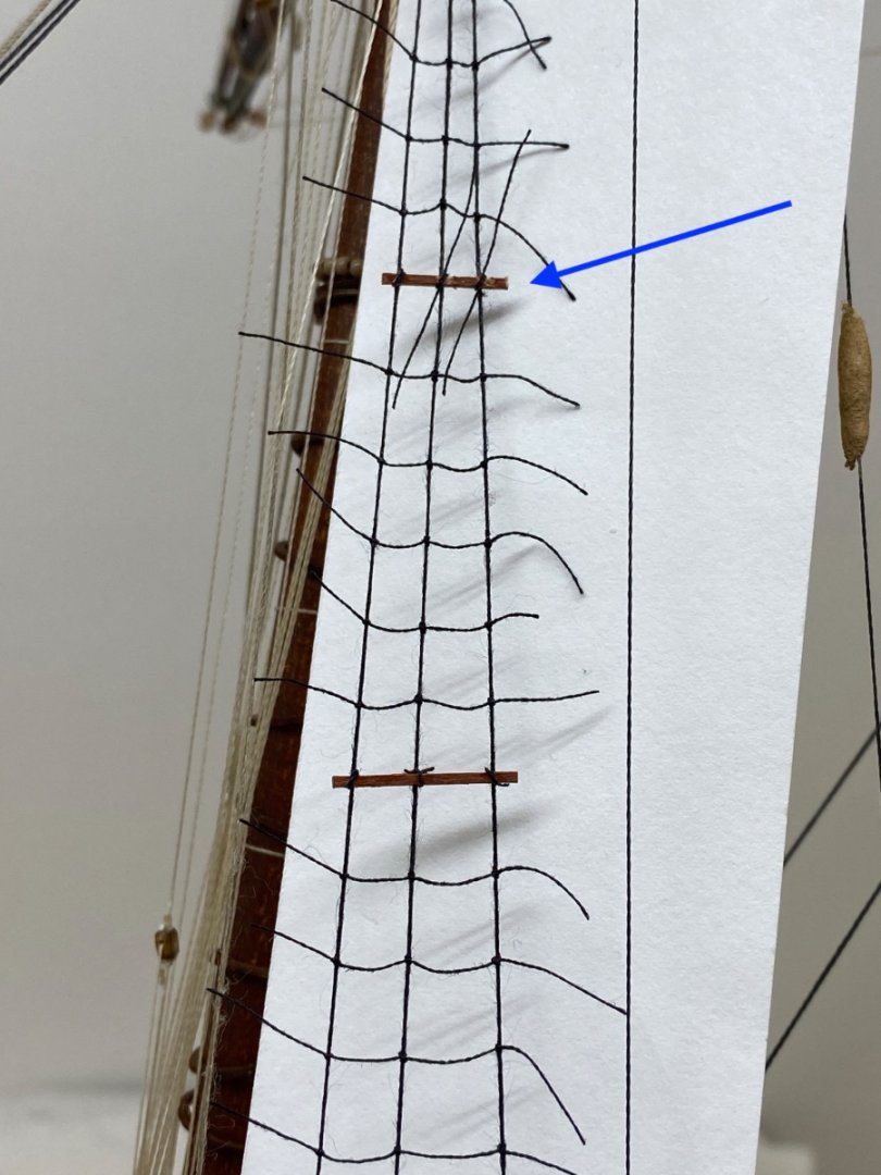
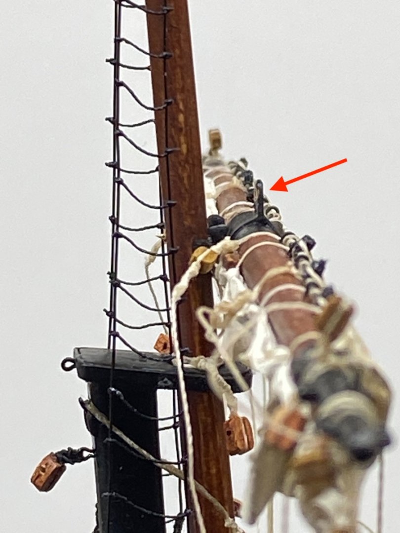
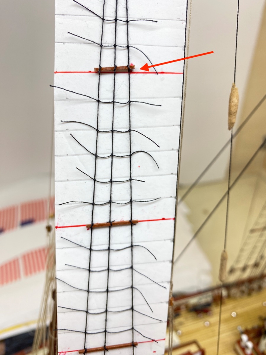
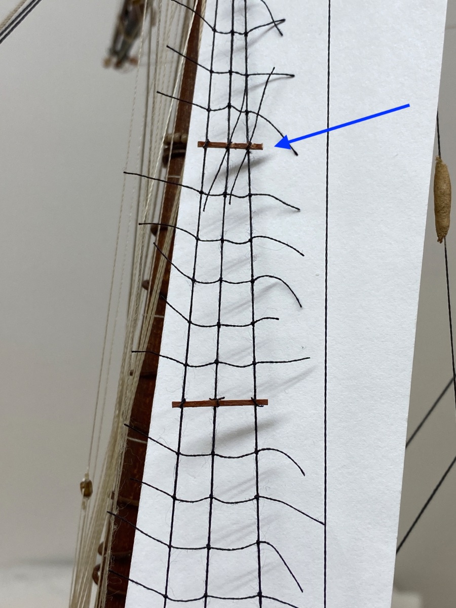
Port fore shroud ratlines. Here another misaligned (red arrow) wood batten was corrected (blue arrow).

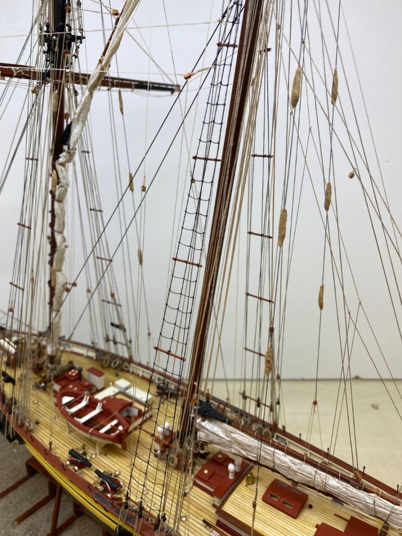
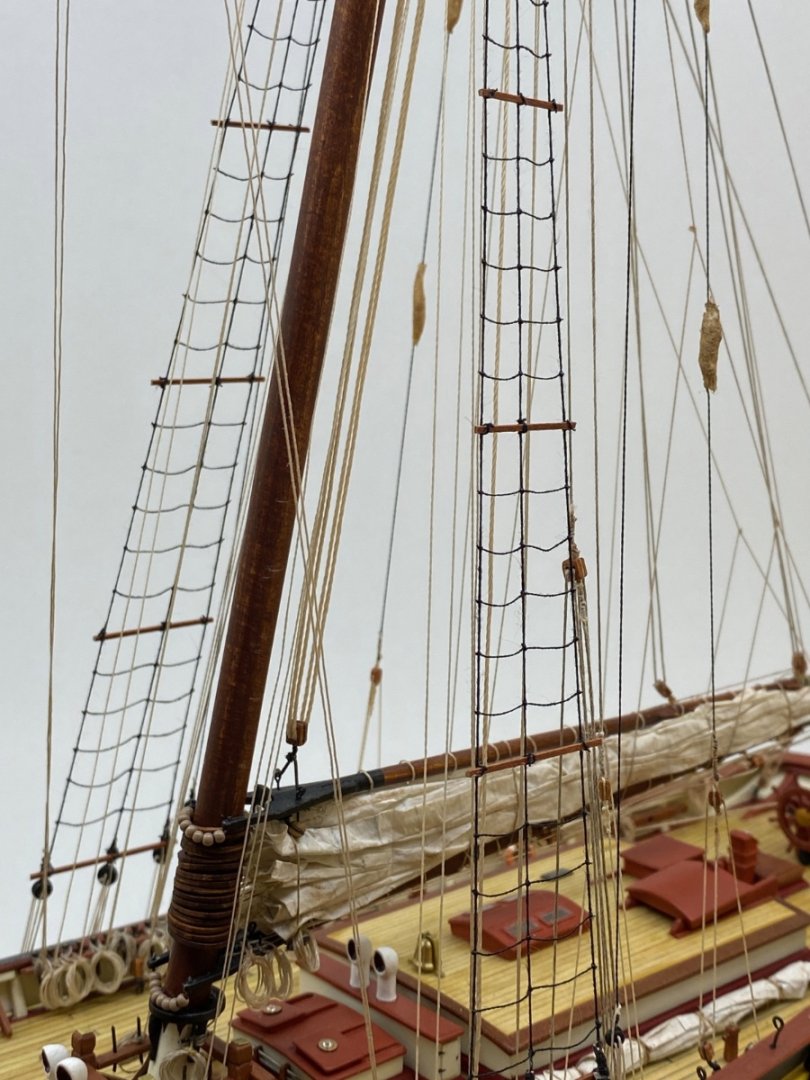
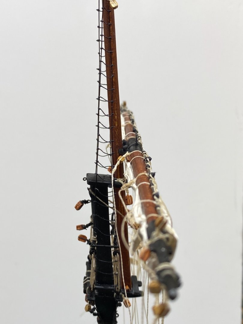
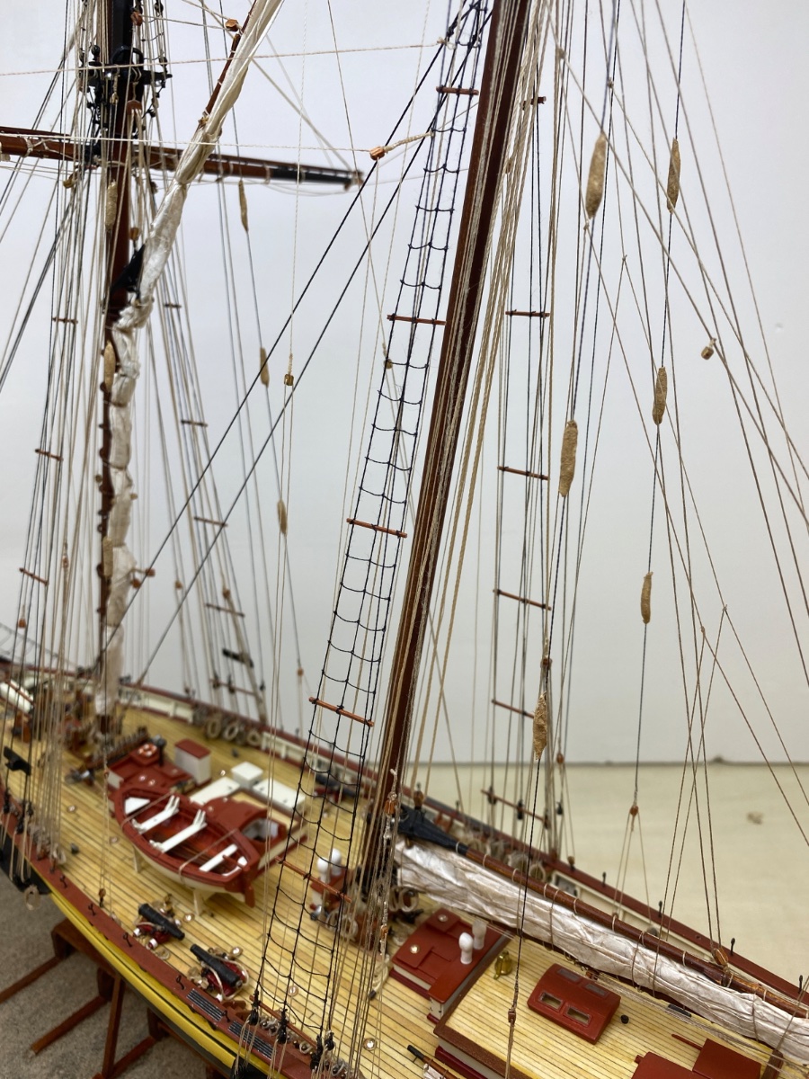
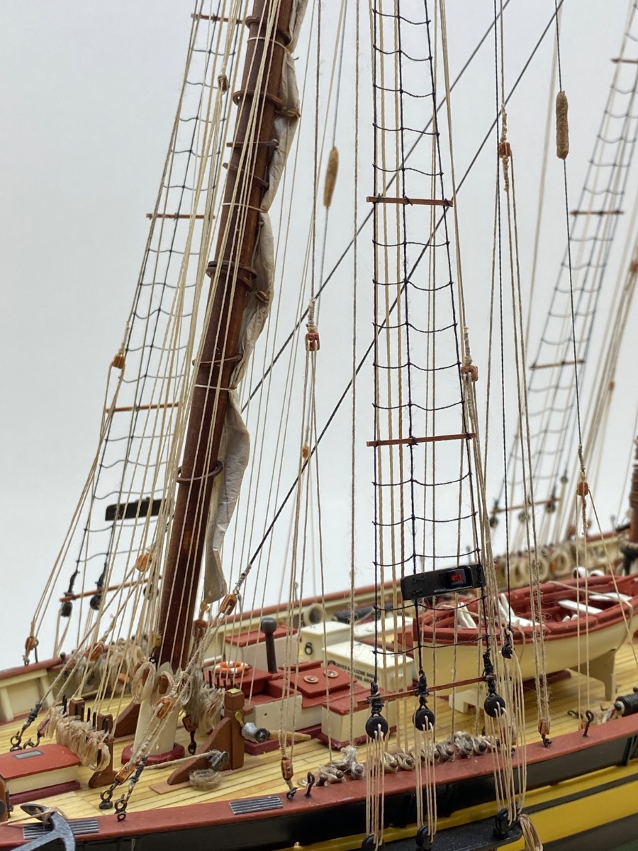
All the ratlines were finished. Here are some photos showing them altogether.
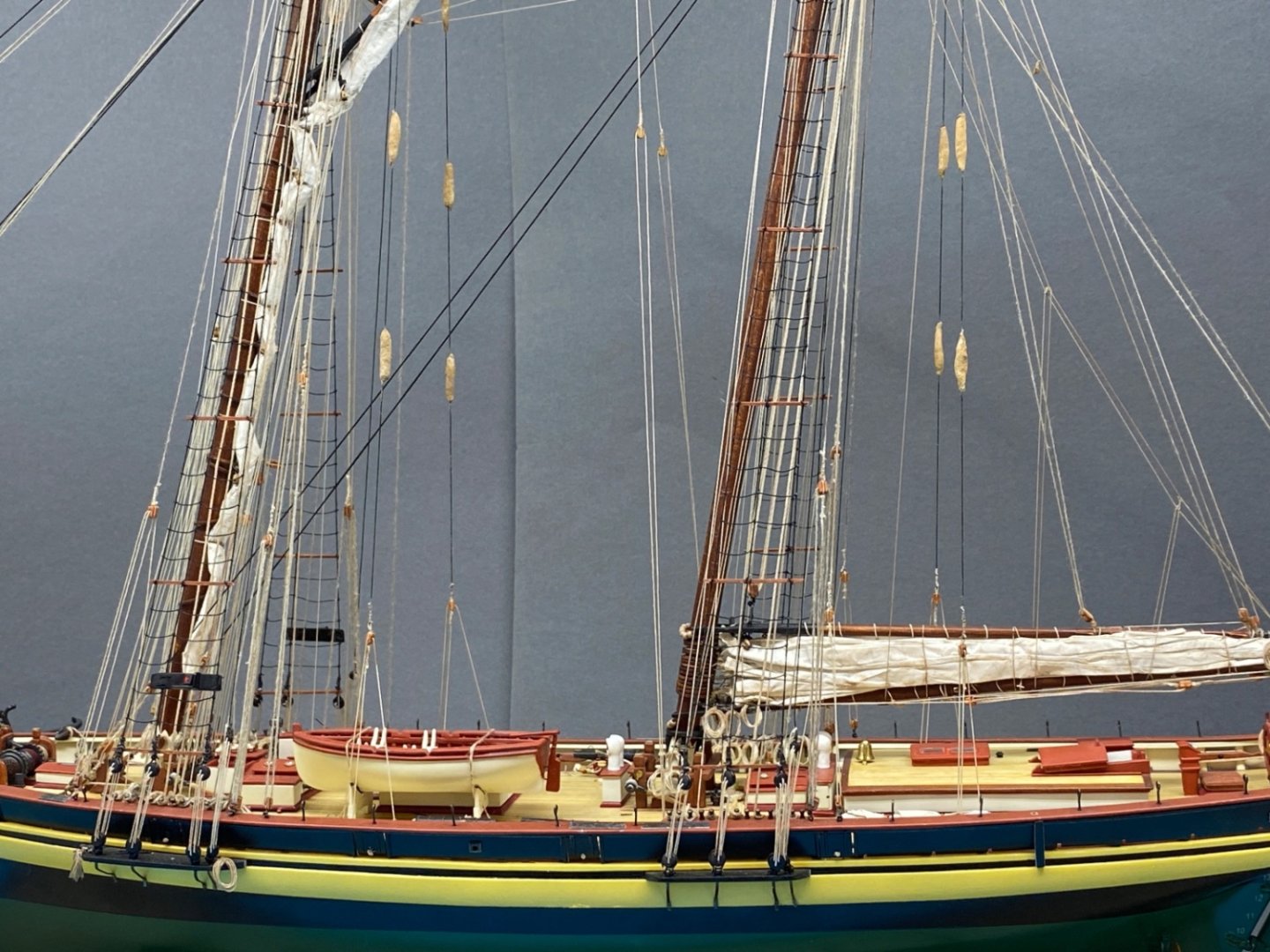

There were a couple of minor steps between shrouds / running light and sheer poles and ratlines. In order to maintain the subject integrity , I purposefully skipped them. Those steps will be dealt with the coming posts.
-
9 hours ago, allanyed said:
Hi Halit!
Your sails are fantastic!!! Easily some of the best on any build log here at MSW.
Is the white thread used for the coils from the kit?
Allan
Hi Allan!
Thanks a lot for your comment.
‘White’ is actually (very ?) light tan color. Probably the existing light conditions when the photos were taken caused it. I used the thread from the kit as well as the sewing thread ( cotton and synthetic) I bought later. The thick rigging lines of throat halliards, throat and peak halliard tackles, main sheet, fore lower yard lift and fore lower yard truss are from the kit stock ; therefore their coiled ropes are the same. For the thinner ones I do not remember exactly which coiled rope was from the kit. The seizing lines of the blocks were the thinnest thread (cotton) I had and were bought later. There was a third group of tan colored threads also and they were all cotton ( the fuzzy ones) thread lines from Artesania Latina company. The same applies to black colored threads also. Although black thread was easy to find in all sizes, both cotton and synthetic ; for tan color it was not so. At least for synthetic ones. However I discovered later when the model was finished that embroidery supply stores do have all colors, all sizes and both cotton or synthetic….
Hopes this answers your question
Have a nice day..
Halit
-
50 minutes ago, yvesvidal said:
Your work on the rigging of this ship, is incredible. I am wondering if you have not sailed the real thing.....
You are a perfectionist.
Yves
Thanks a lot for nice complimants .
I just try to do my best ..
My experience with the real thing is close to none and limited to leisure rowing in my younger ages..😌
-
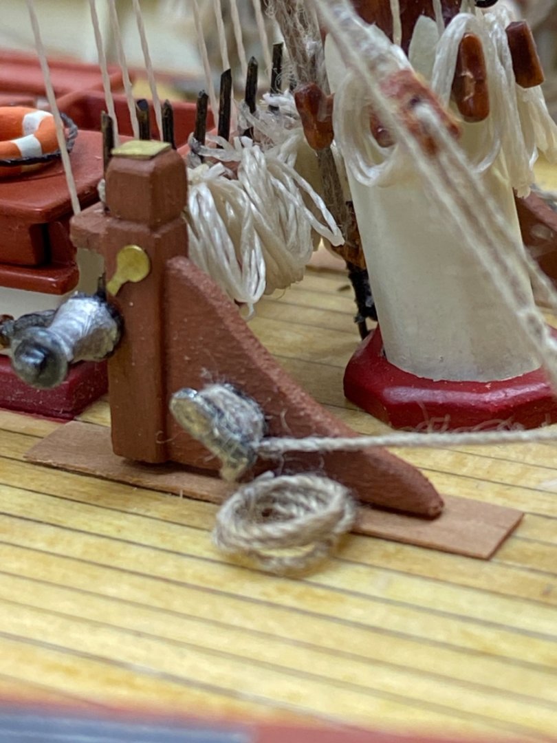
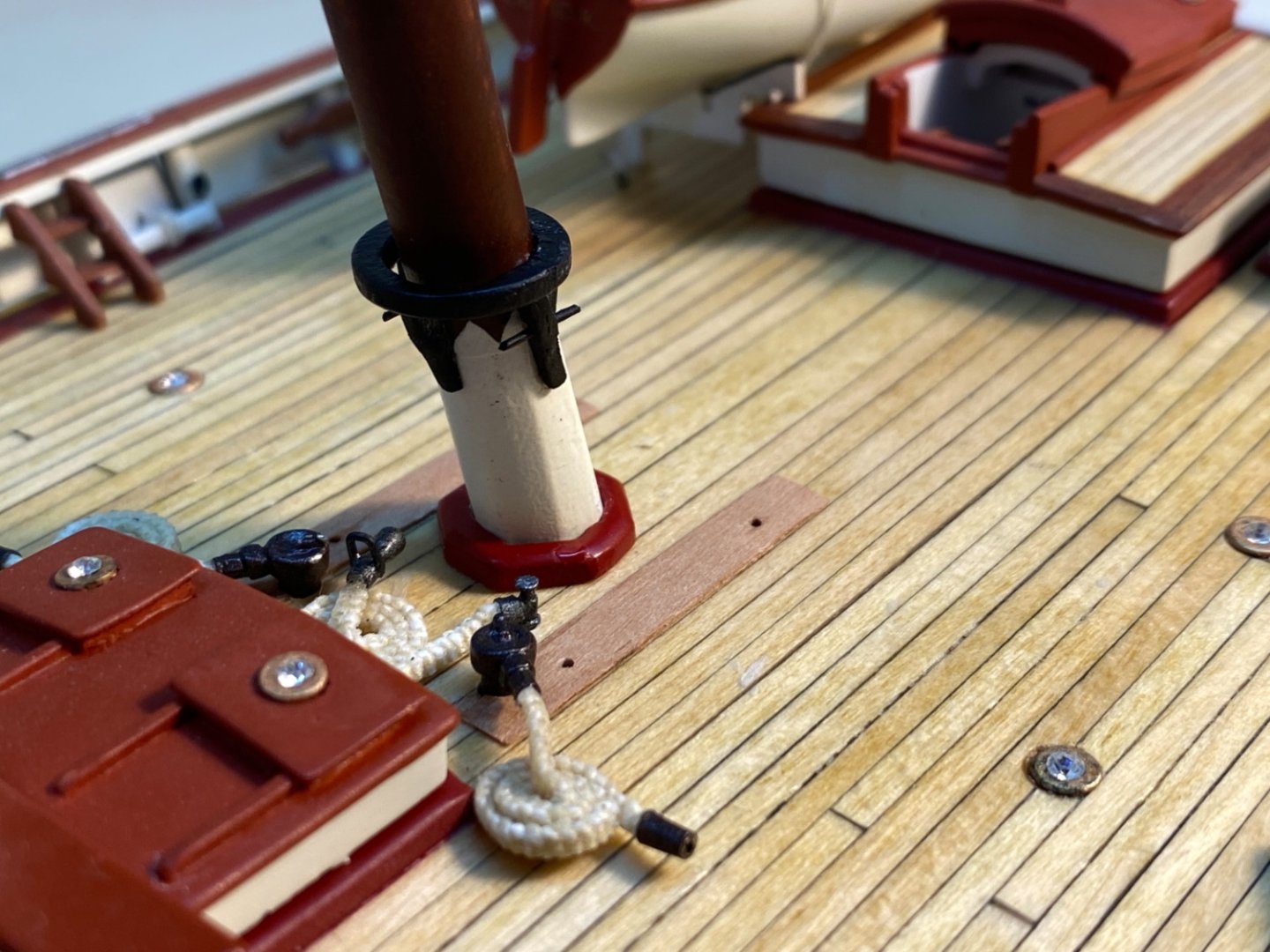
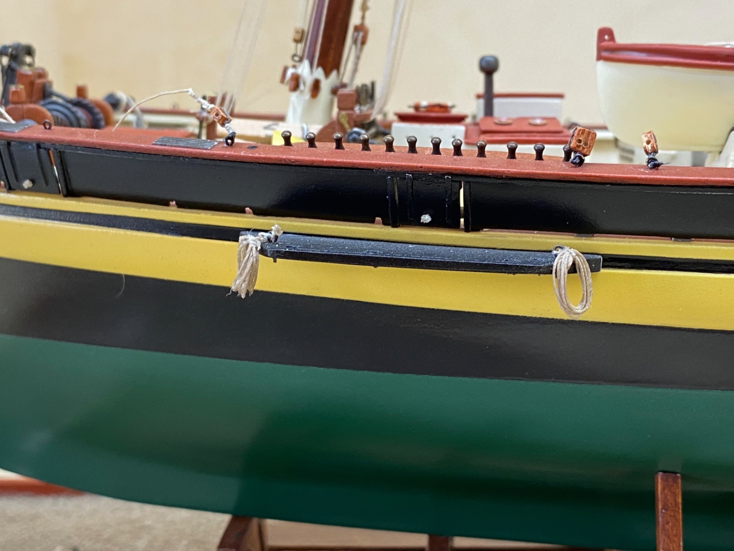
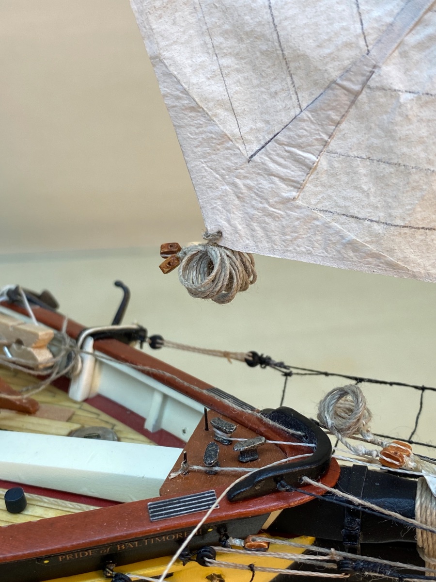
I continued the build by creating coiled ropes and installing them to belaying points without forgetting using the same color and size thread for each individual rigging line.
Actually I had prepared some coiled and stowed ropes of some lines of fore sail sheets. But these were done without any particular method and by simply looping threads around an 6 mm diameter dowel several times and tying them overhead knots. They were belayed to eyebolts on the fore chain plate platforms and wetted by diluted white glue. A weight (plastic clamp) was hanged and the shape of the coiled rope was then
achieved.

Starboard side coiled ropes of Jib sheet (fore) and Jib Topsail sheet (aft).
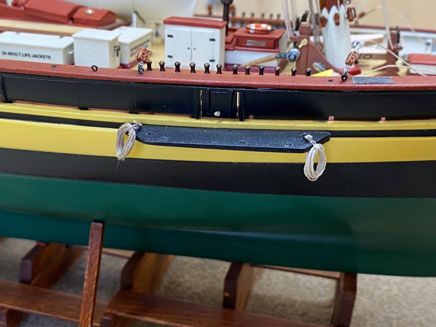
Port side coiled ropes of rigging lines of Jib (fore) and Jib Topsail (aft) sheets.

Remember Tom Lauria ? His videos on 'Making silkspan sails' ? I came across his name again when I searched internet for 'coiled ropes' and he was describing his method of making scale rope hanks this time. Here is his method.
I tried his method exactly with the same steps but I did not like my result, probably due to limitations of 1:64 scale. In scales 1:48 or bigger I am sure good results with his method can be achieved.
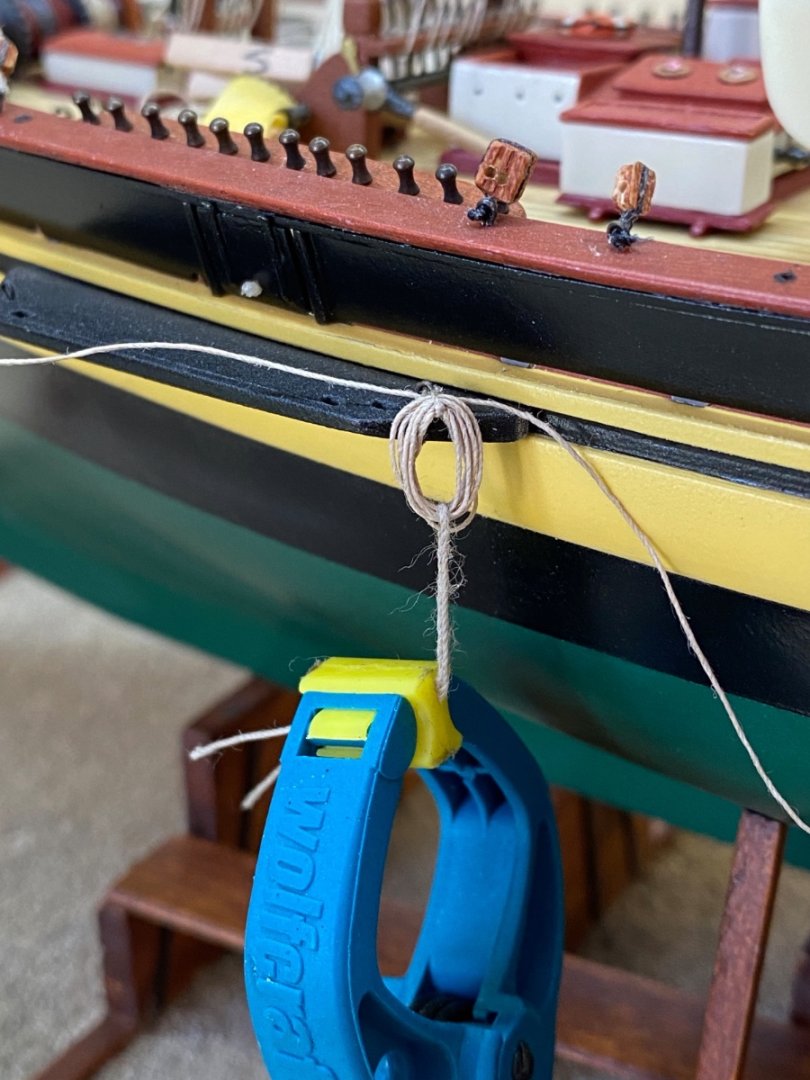
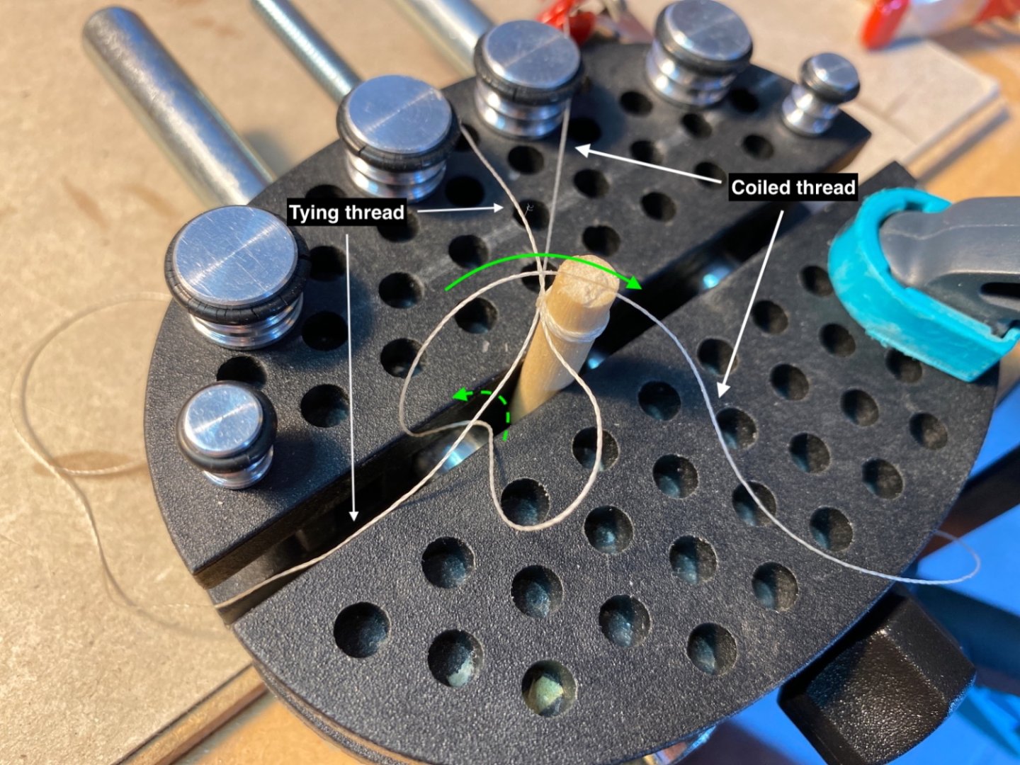
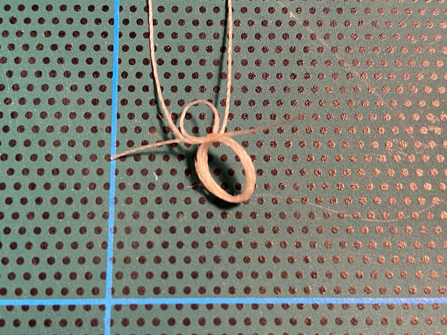
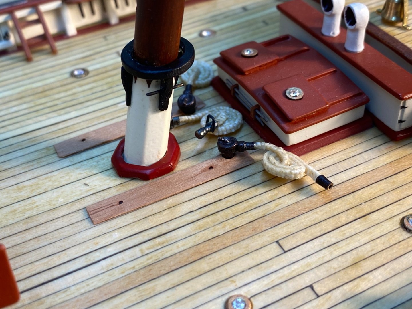
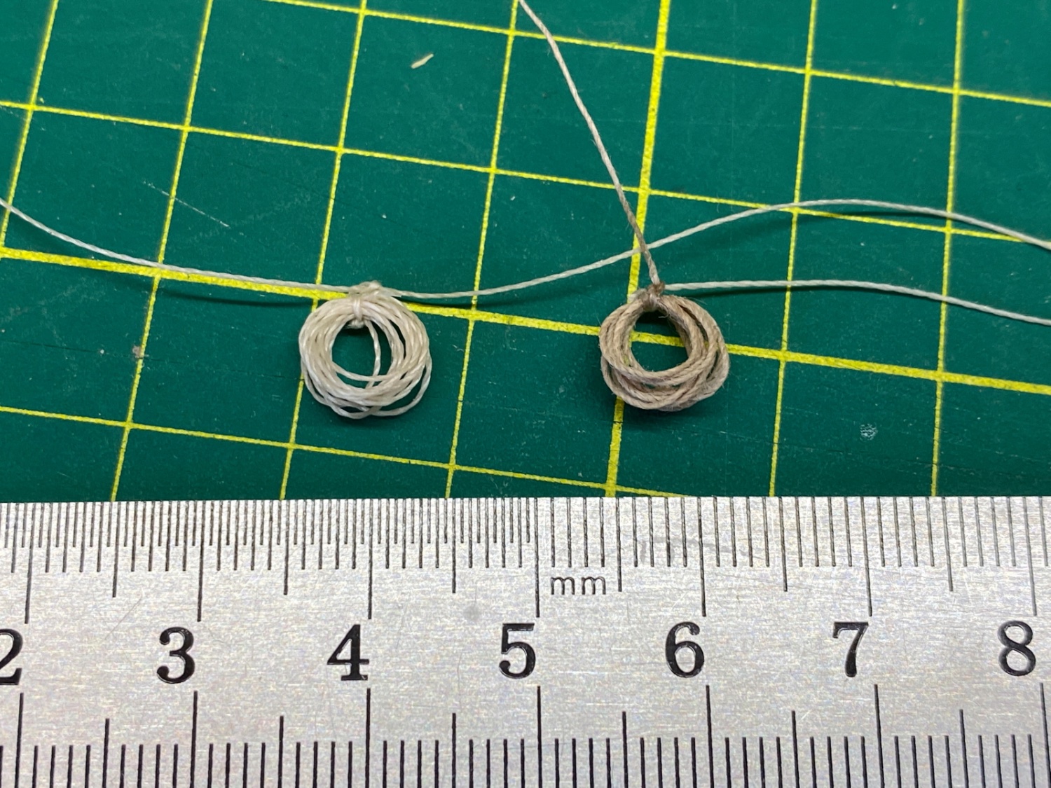
So I decided to find a way of my own. As the coiled ropes I described at the beginning of this post were seized directly to eyebolts just like the way they were seized in the real ship, the final shape of the coiled ropes was OK. However the coiled ropes which were to be hanged to belaying pins must also have some kind of small loop at their top besides the coiled part. These small extra loops then can be inserted to the belaying pins. Here is how I did it .
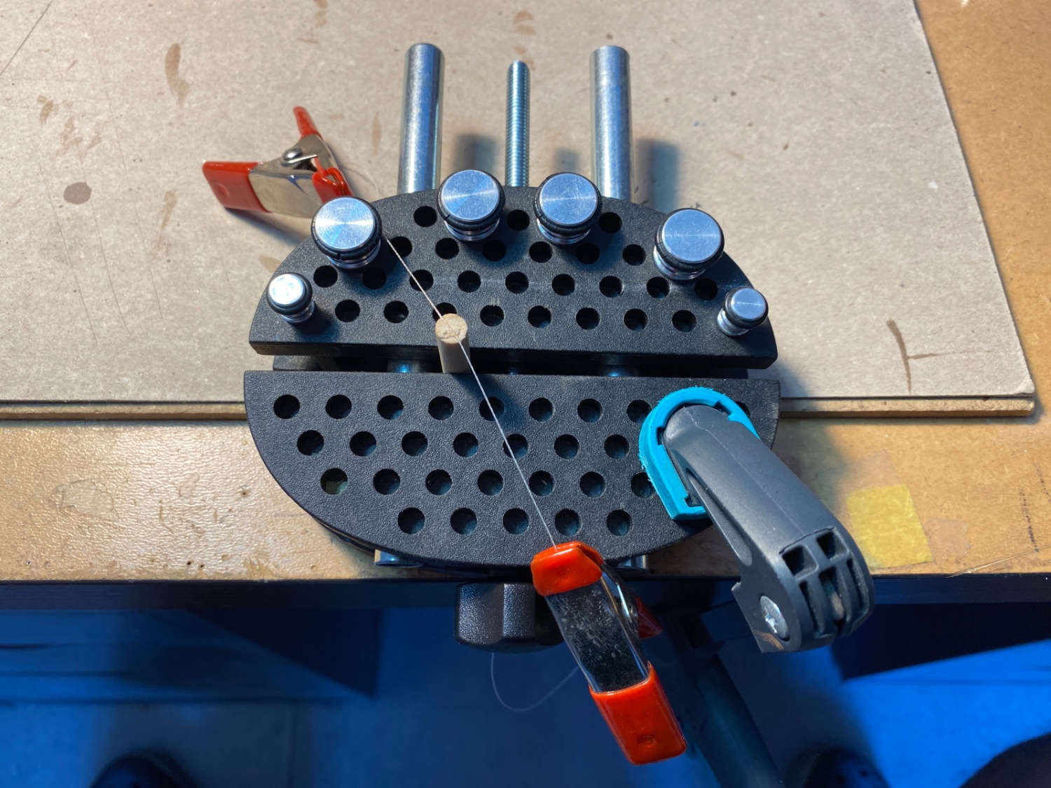
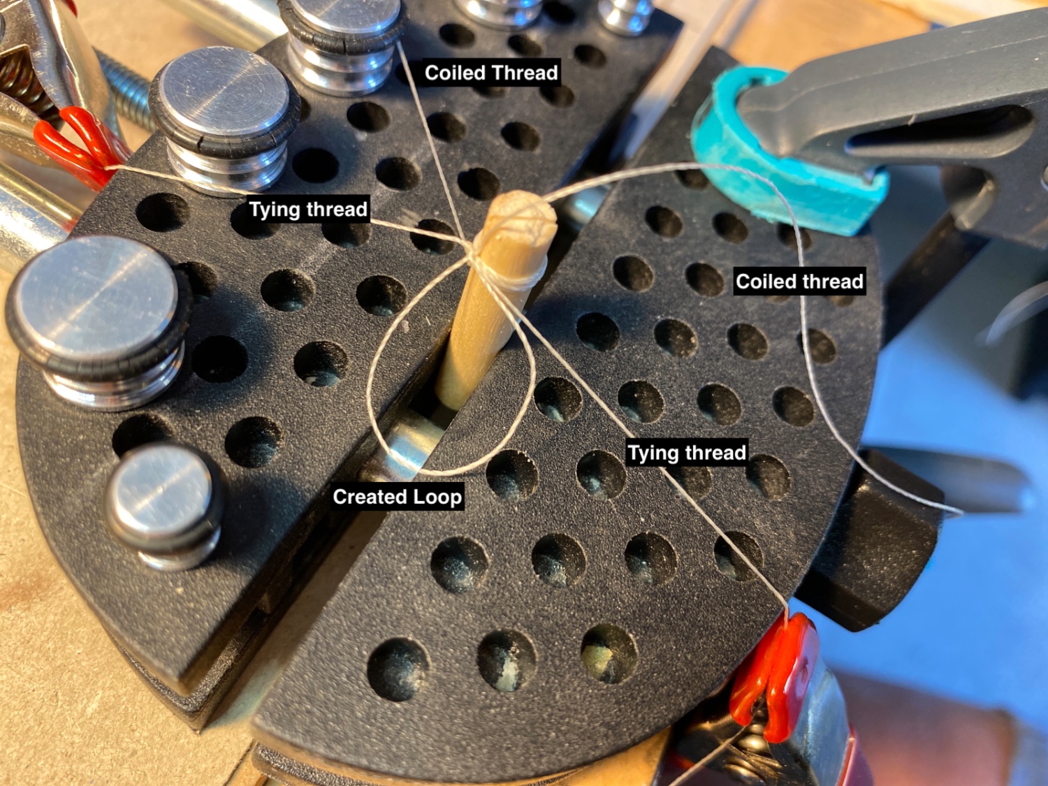
Depending on the size of the coiled rope 5 or 6 mm dowel pieces were used. The dowel piece was fixed in a vise (Amati Model). A groove was created at the top of the dowel. A short piece of thread with the same color but with a smaller size diameter than the 'to be coiled rope' is fixed with two clamps and placed in the dowel top groove. Lets call this 'tying thread'

Then the to be coiled rope thread was clamped at one end and the free thread was loped around the dowel as many as needed as you see in the following photos.
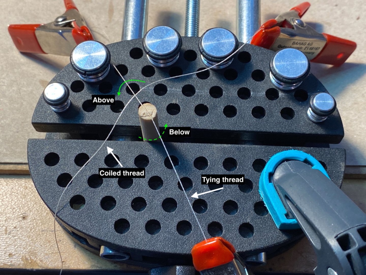
You can see that the tying thread is under the coiled thread now.
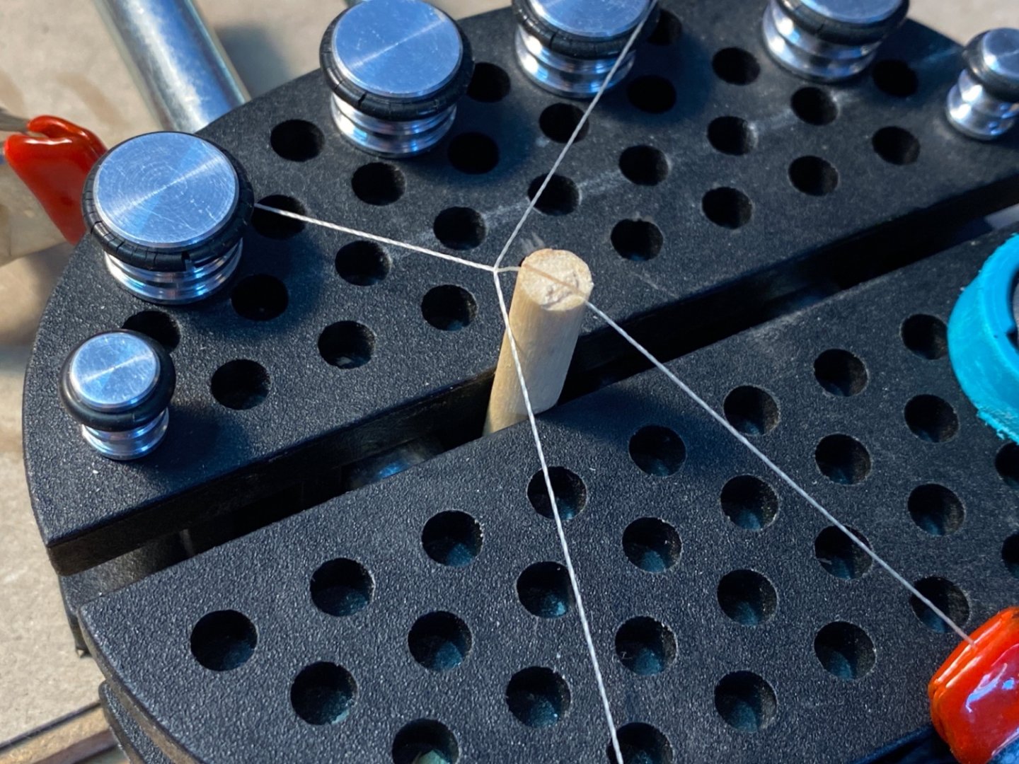
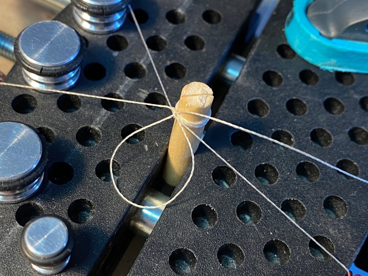
After the necessary number of loops were made by the coiled rope, the free end of the it was also clamped and fixed.
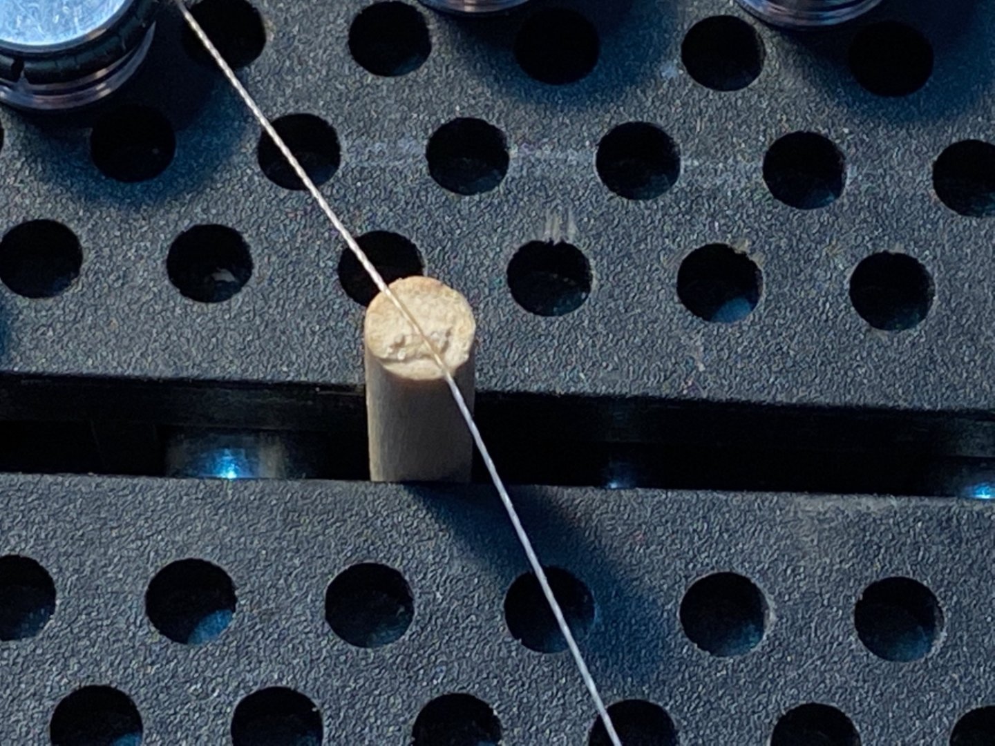
An overhead knot by the 'tying thread' was tied once. An a touch of liquid CA glue was applied to the knot.


This step is critical. As you see in the photo below the coiled thread is passed UNDER the tying thread , then the dowel groove.
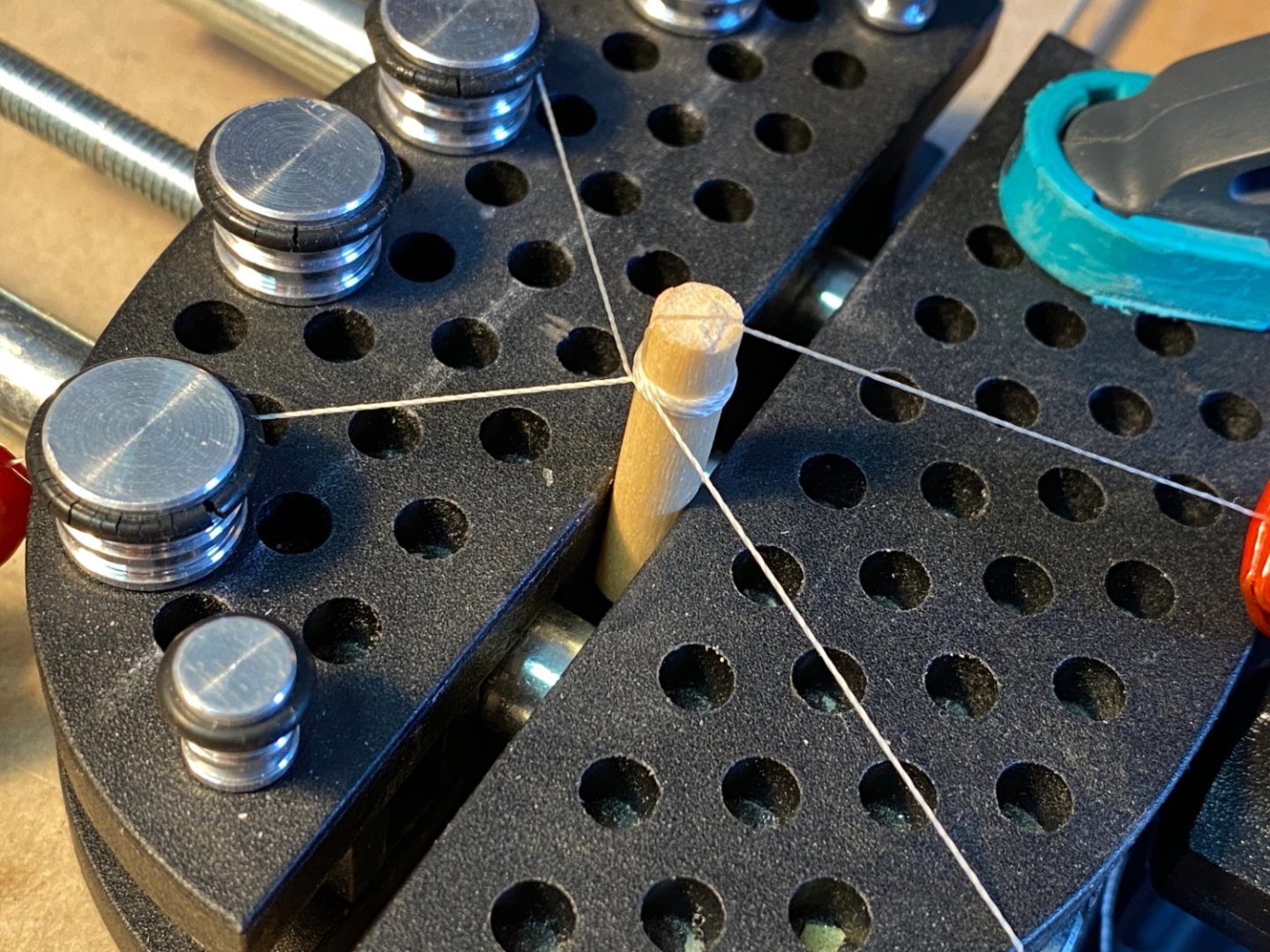
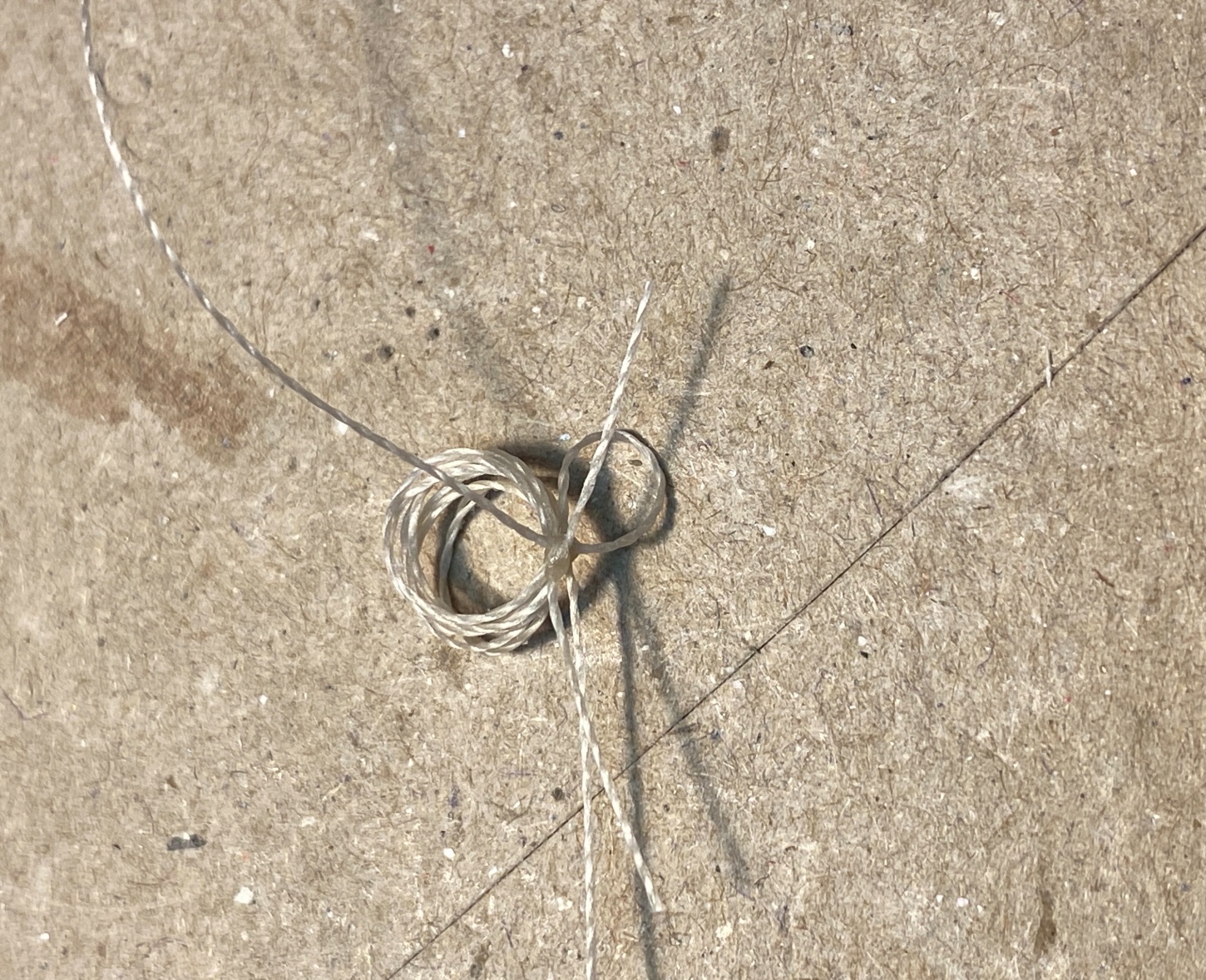
A second overhead knot was tied and a second loop was created.

Coiled thread is pulled until the desired sized loop is created.
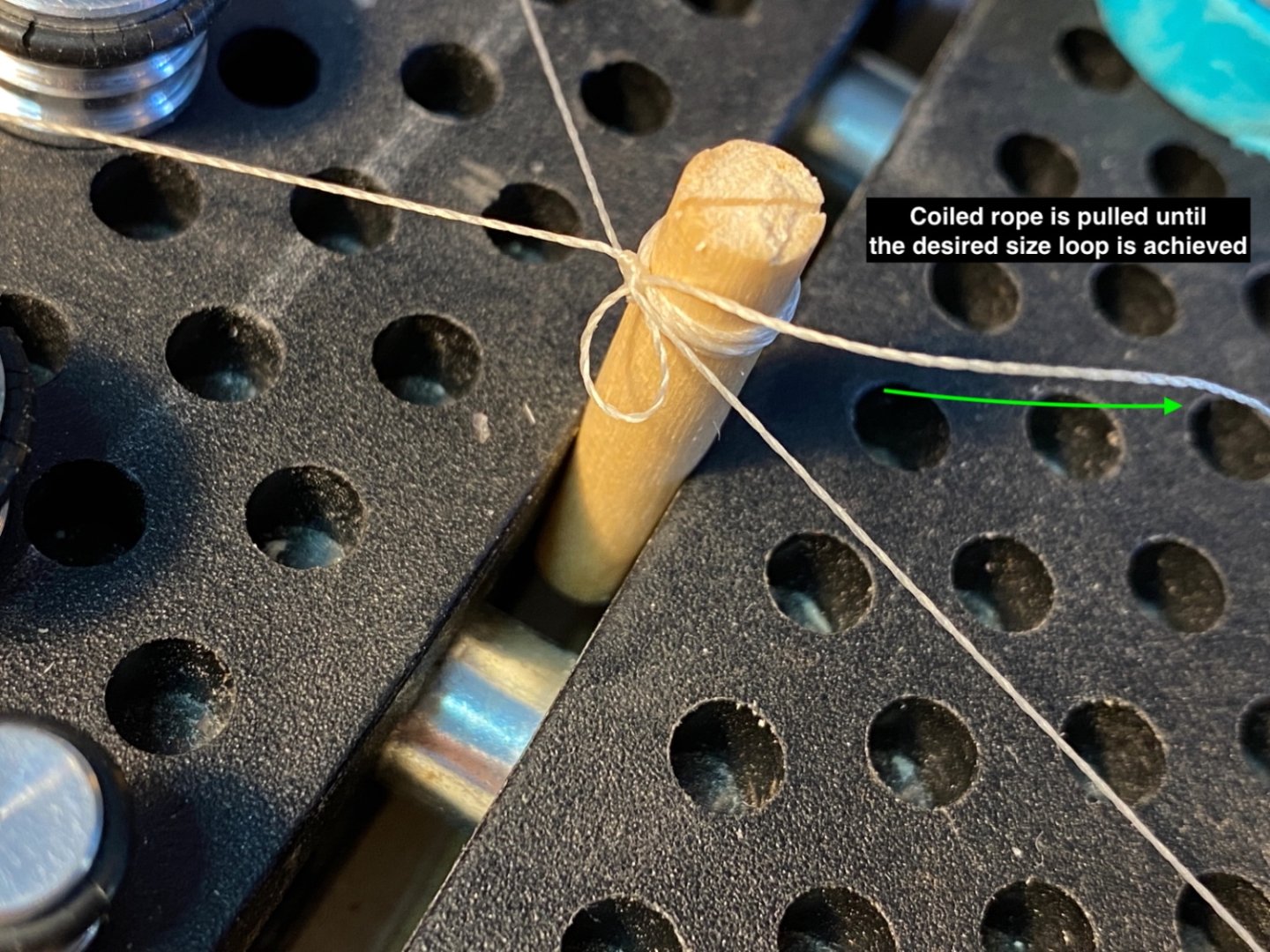
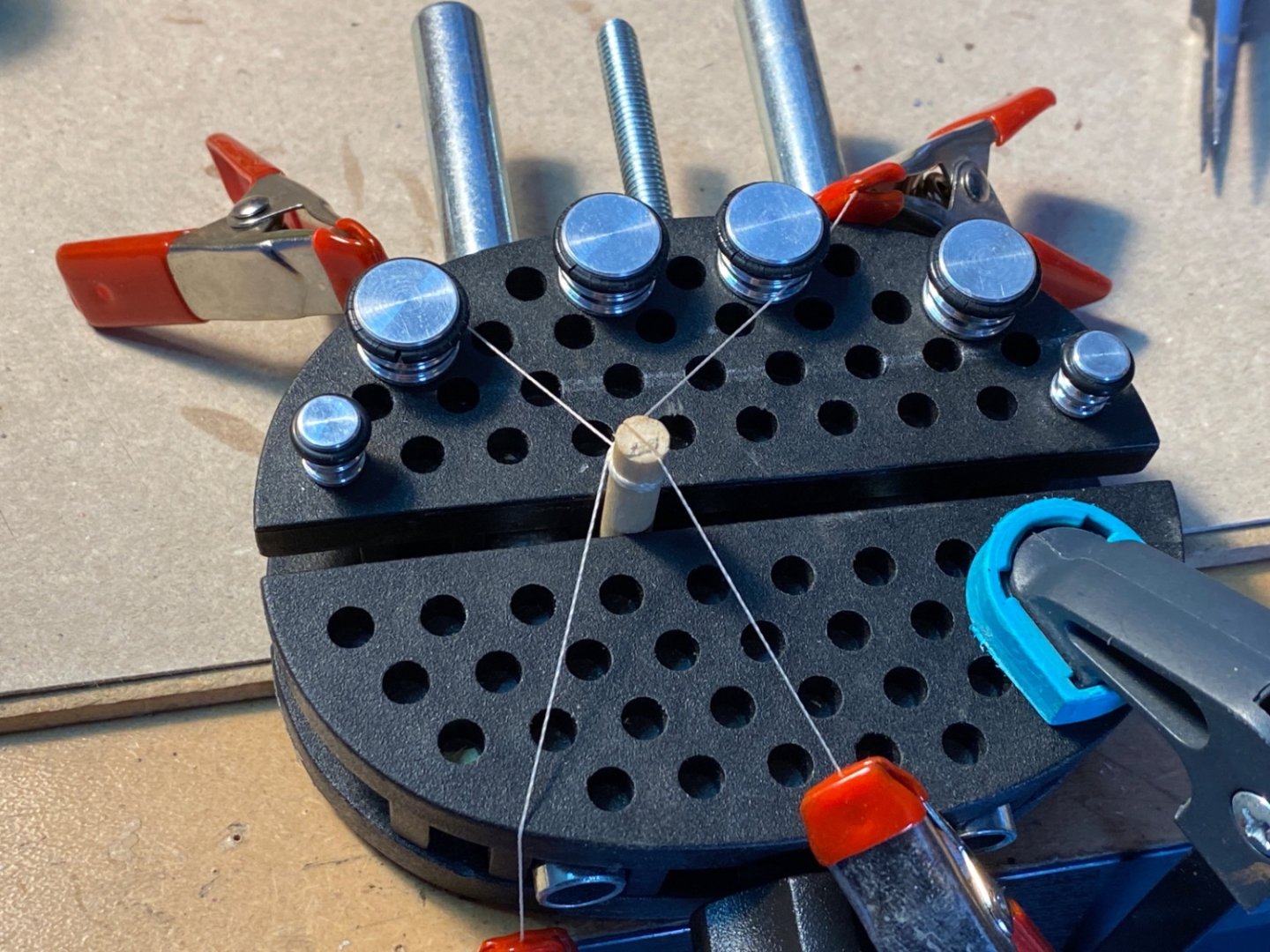
Then tying threads and coiled threads were cut with leaving excess threads on both of them. These excess thread were to be used in the next step.
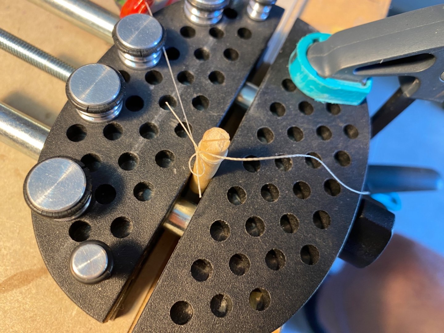
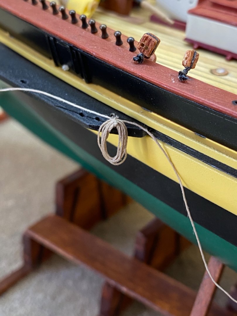
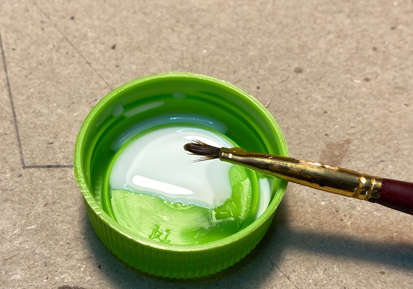
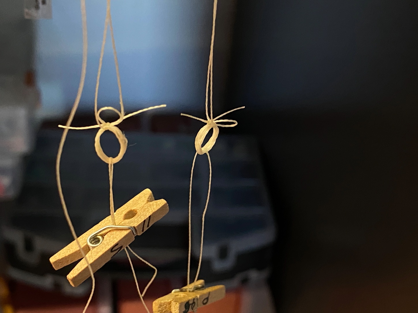
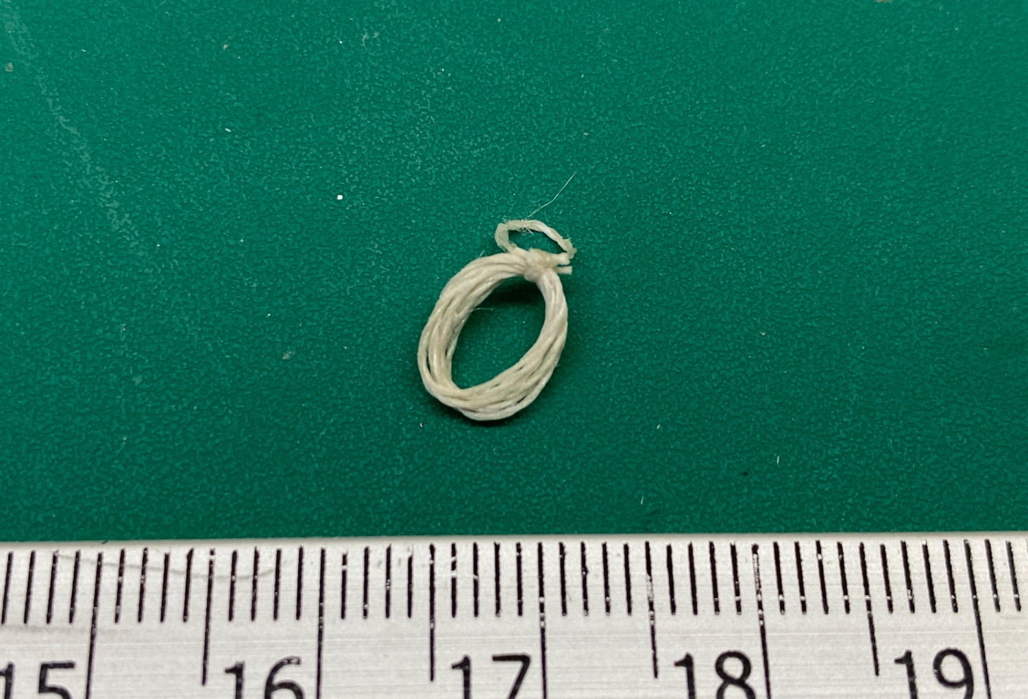
Then the coiled ropes were wetted by water diluted white glue, hanged with some weights and left to dry to shape.

Here is a photo of the setup
After the coiled rope is dry the excess threads were cut and a coiled rope with a small extra loop was achieved.

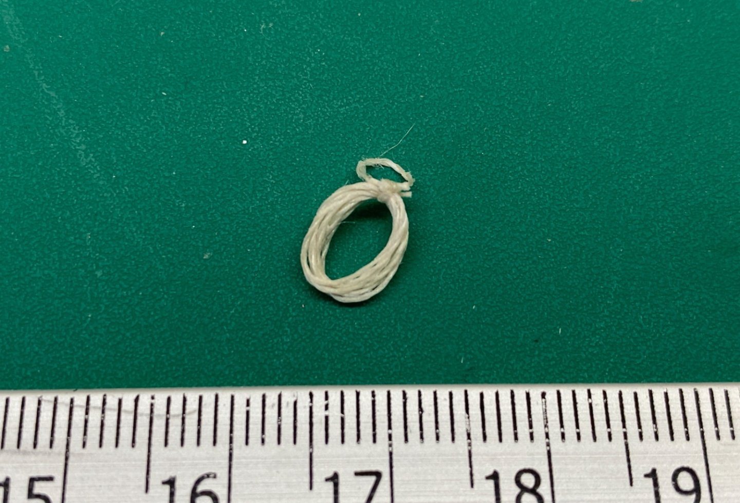
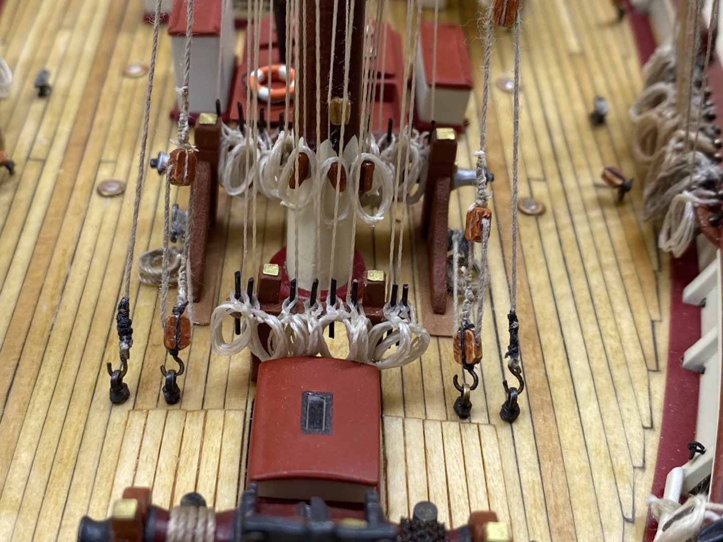
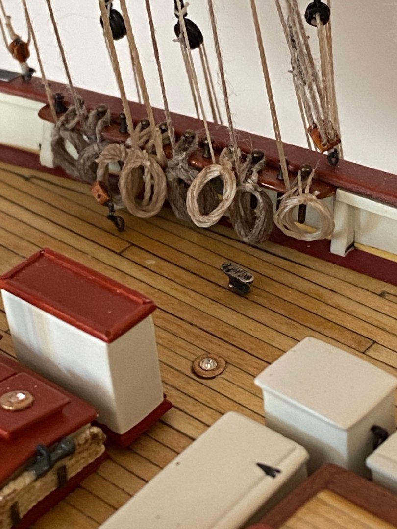
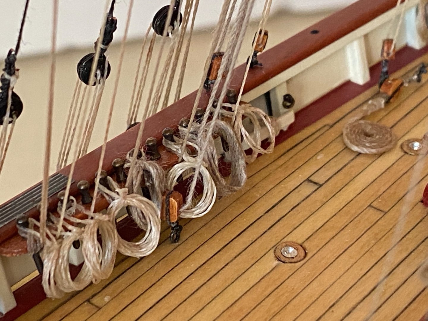
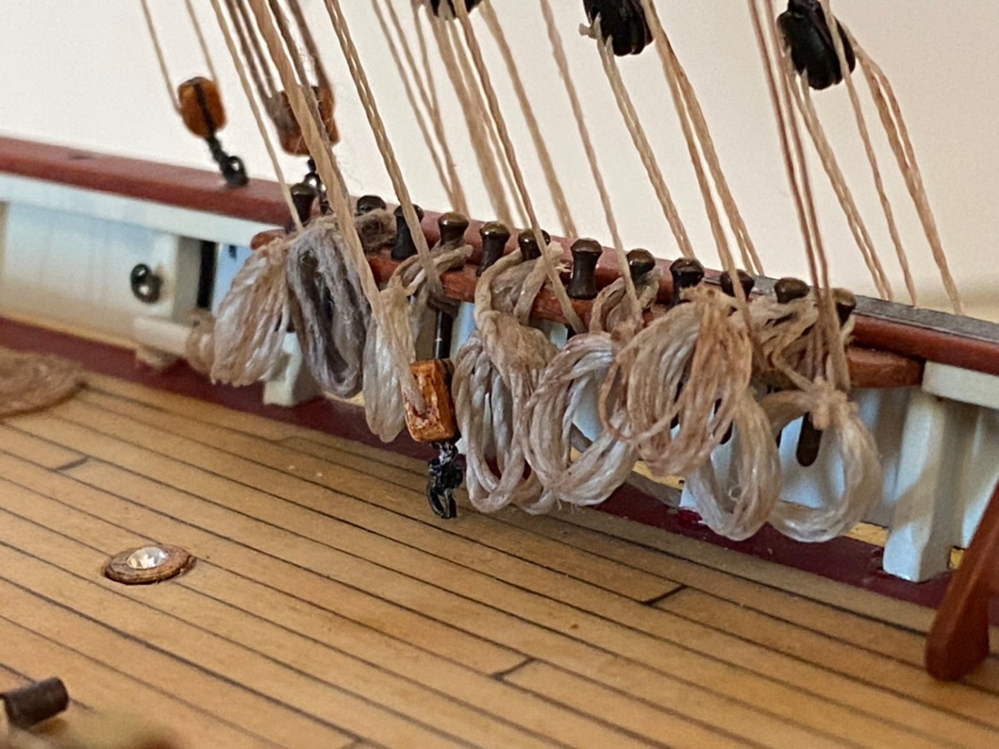
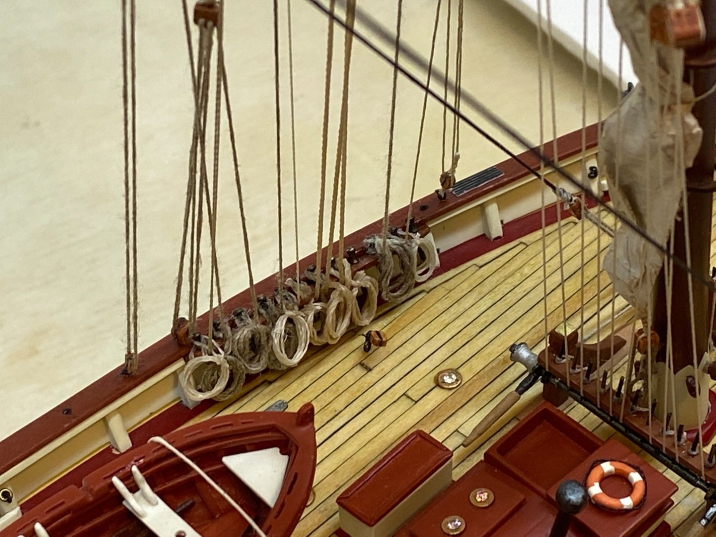
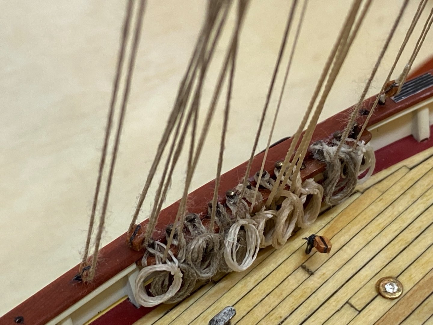
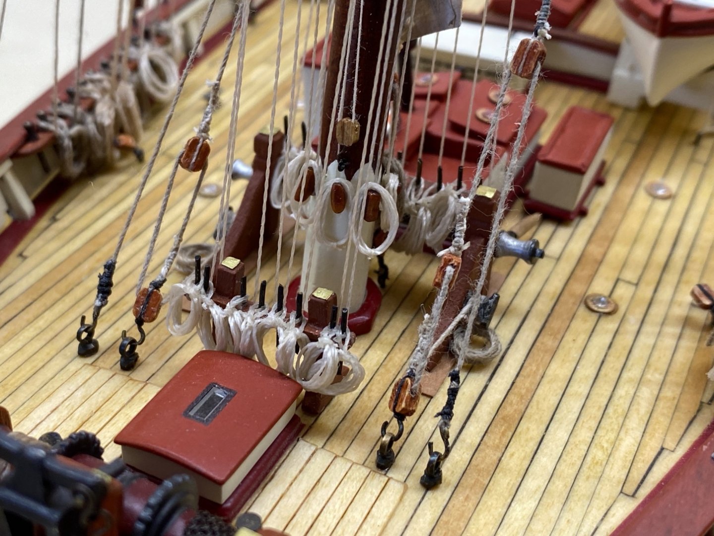
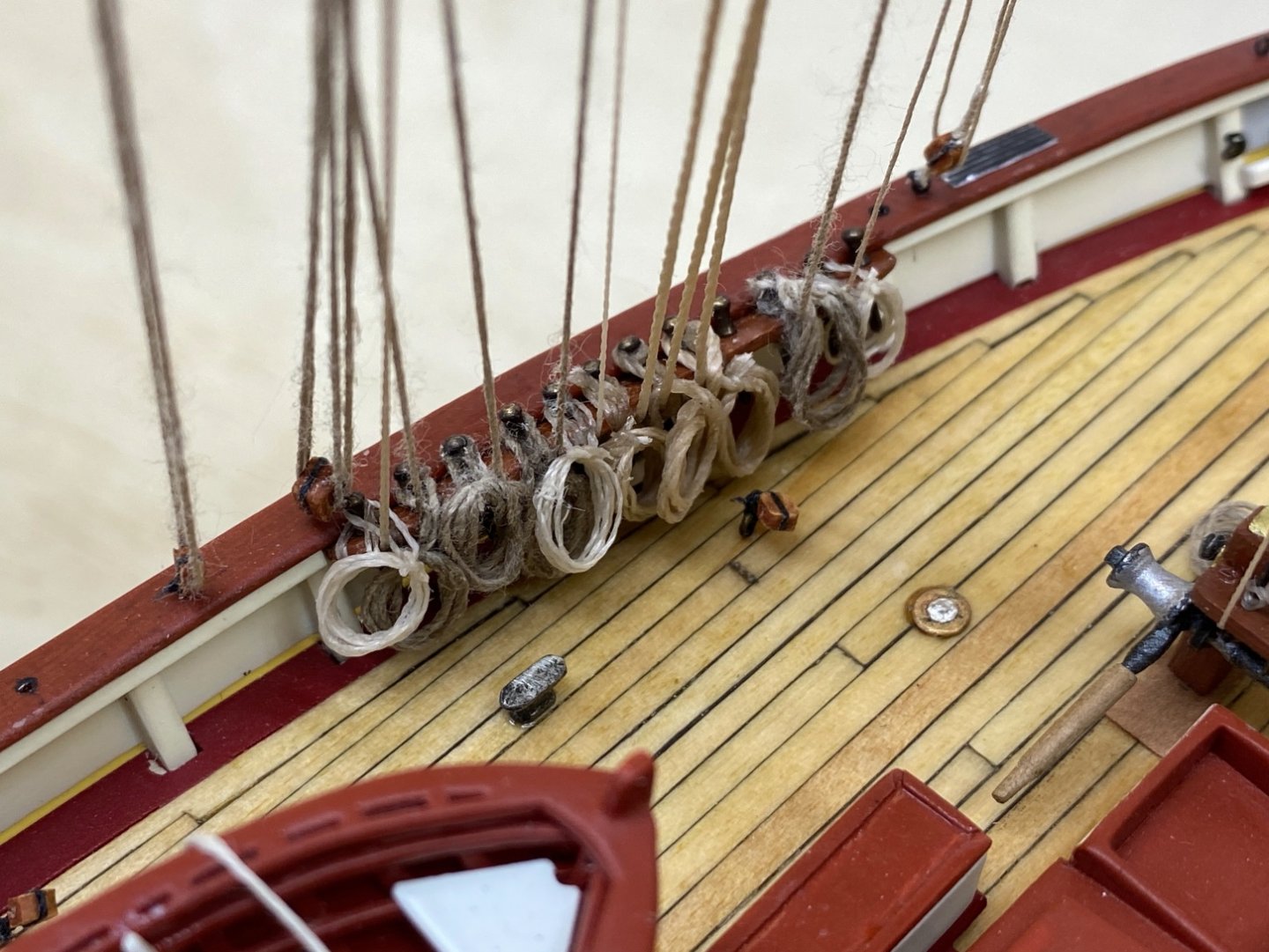
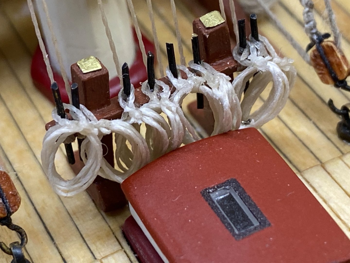
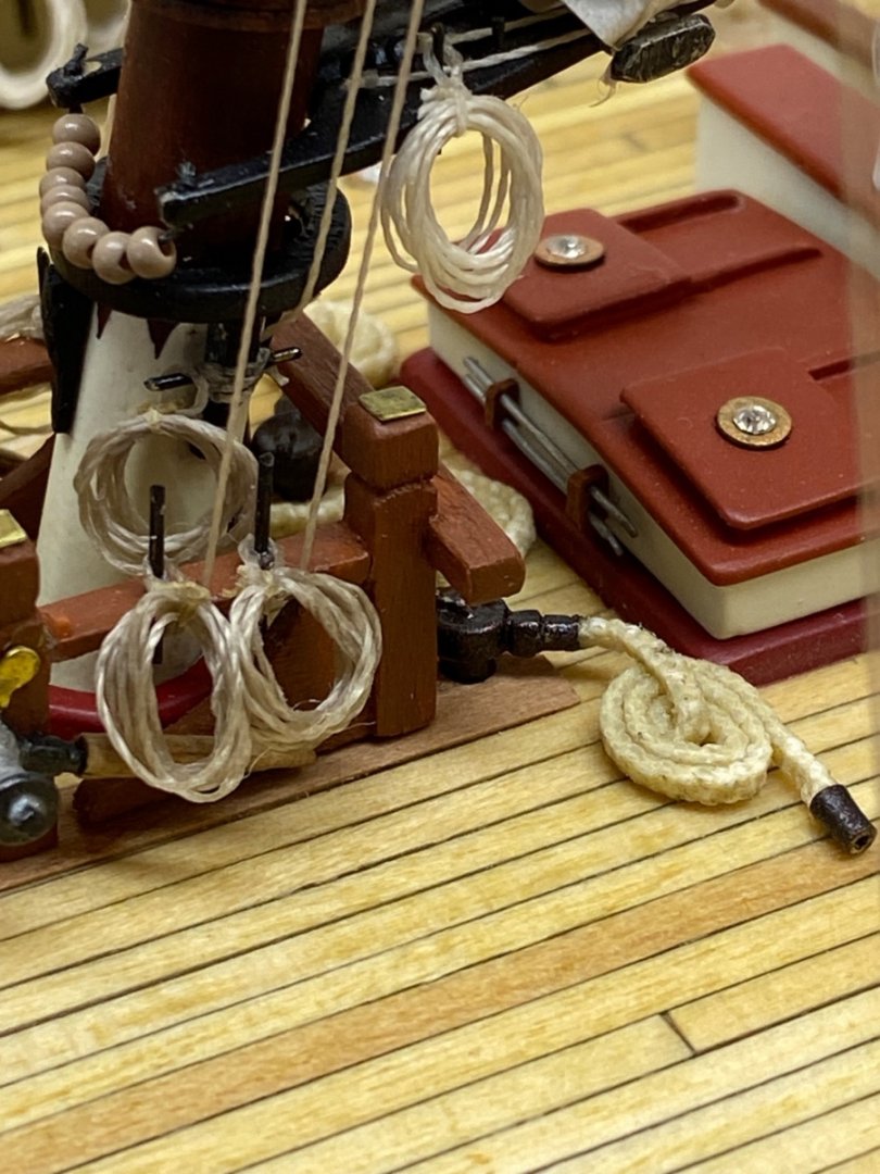
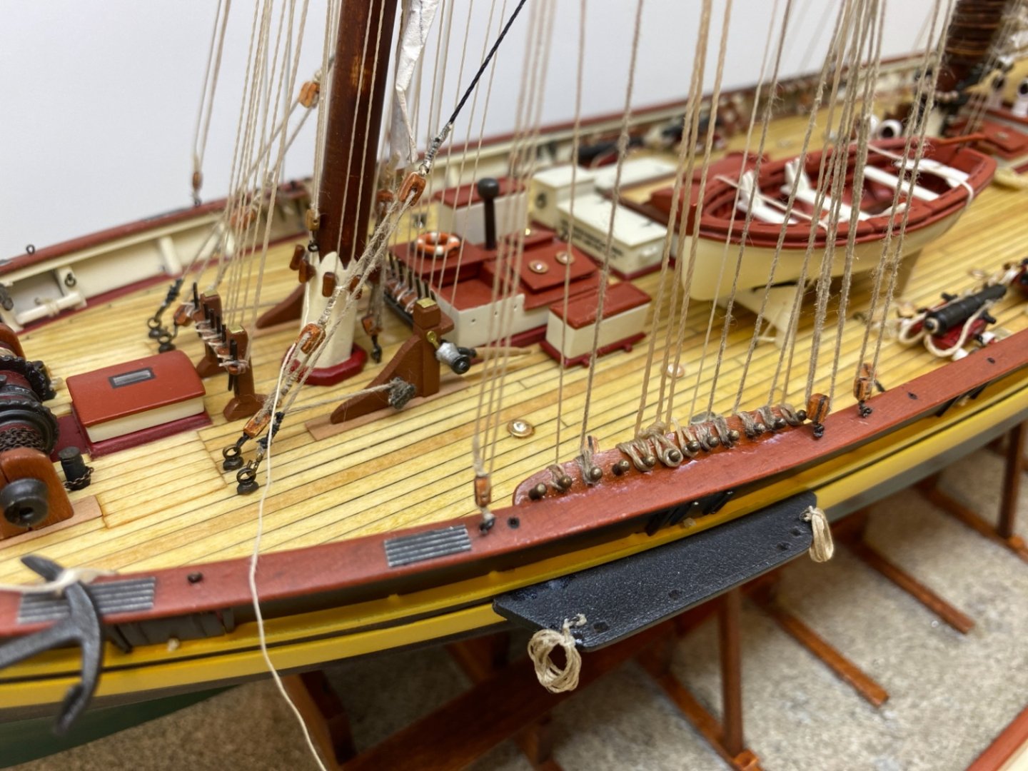
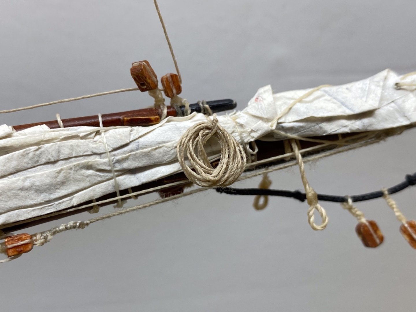
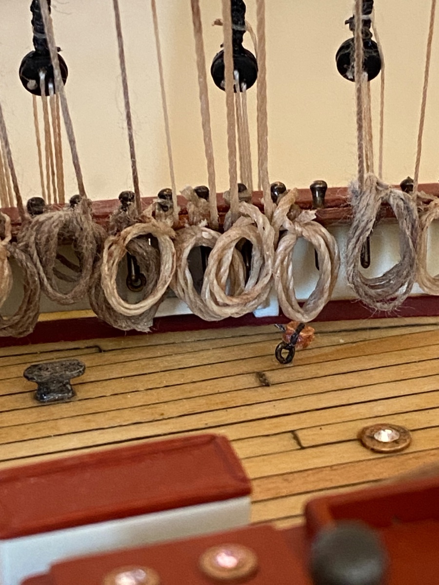
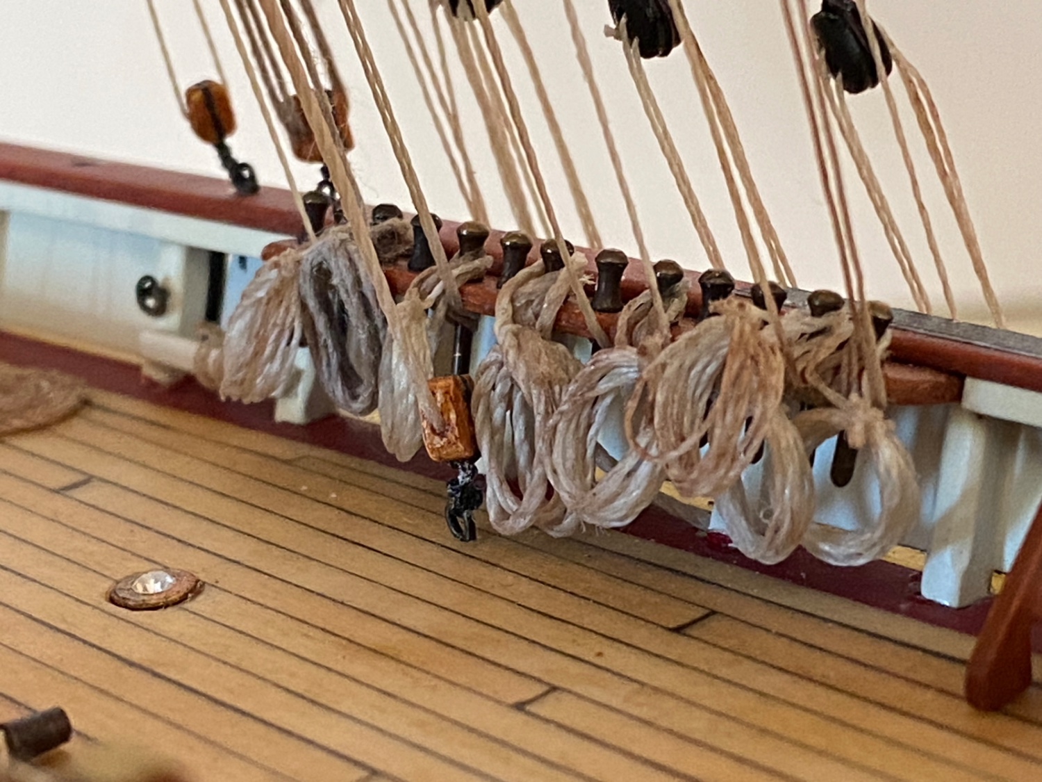
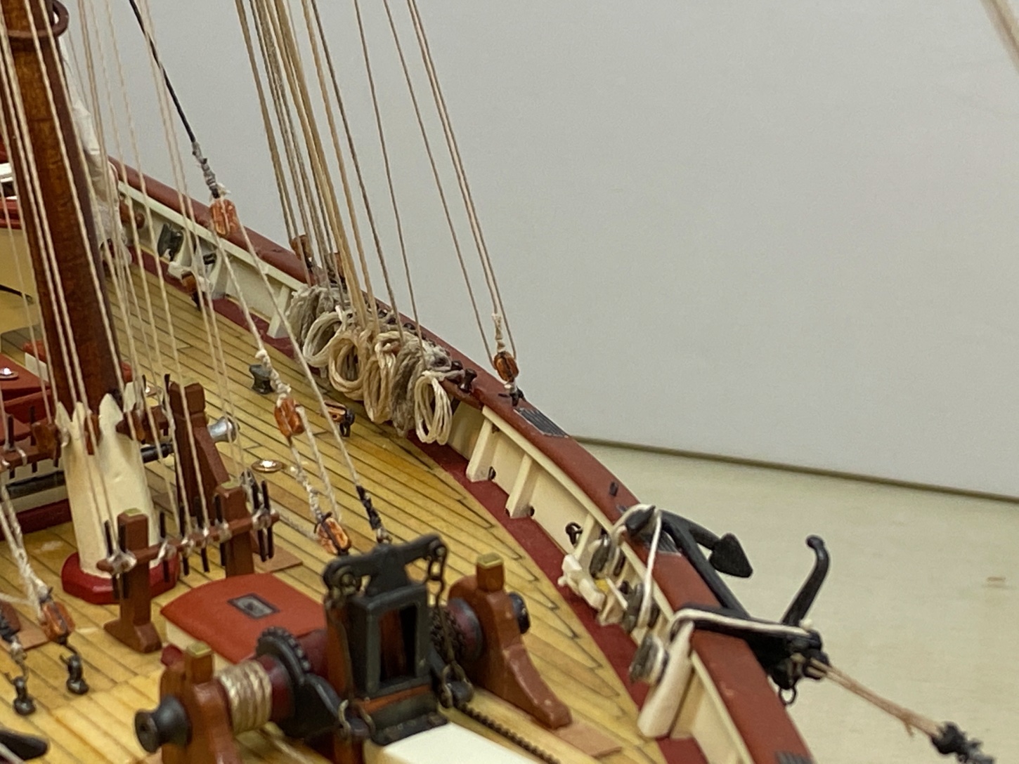
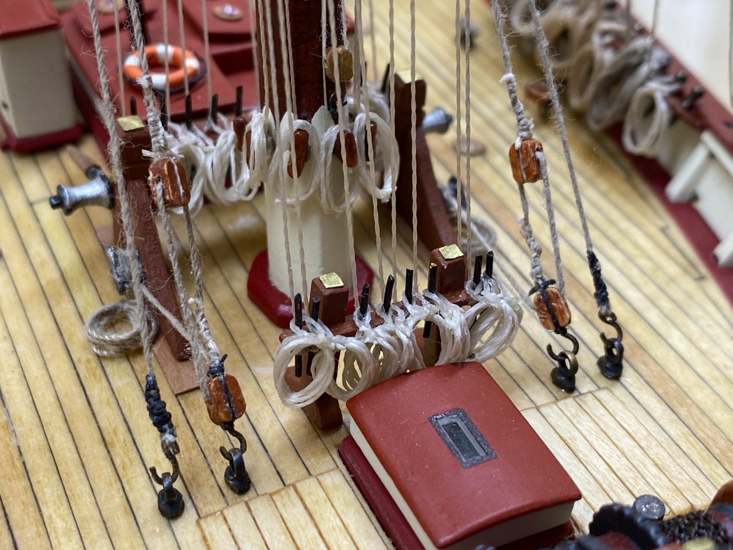
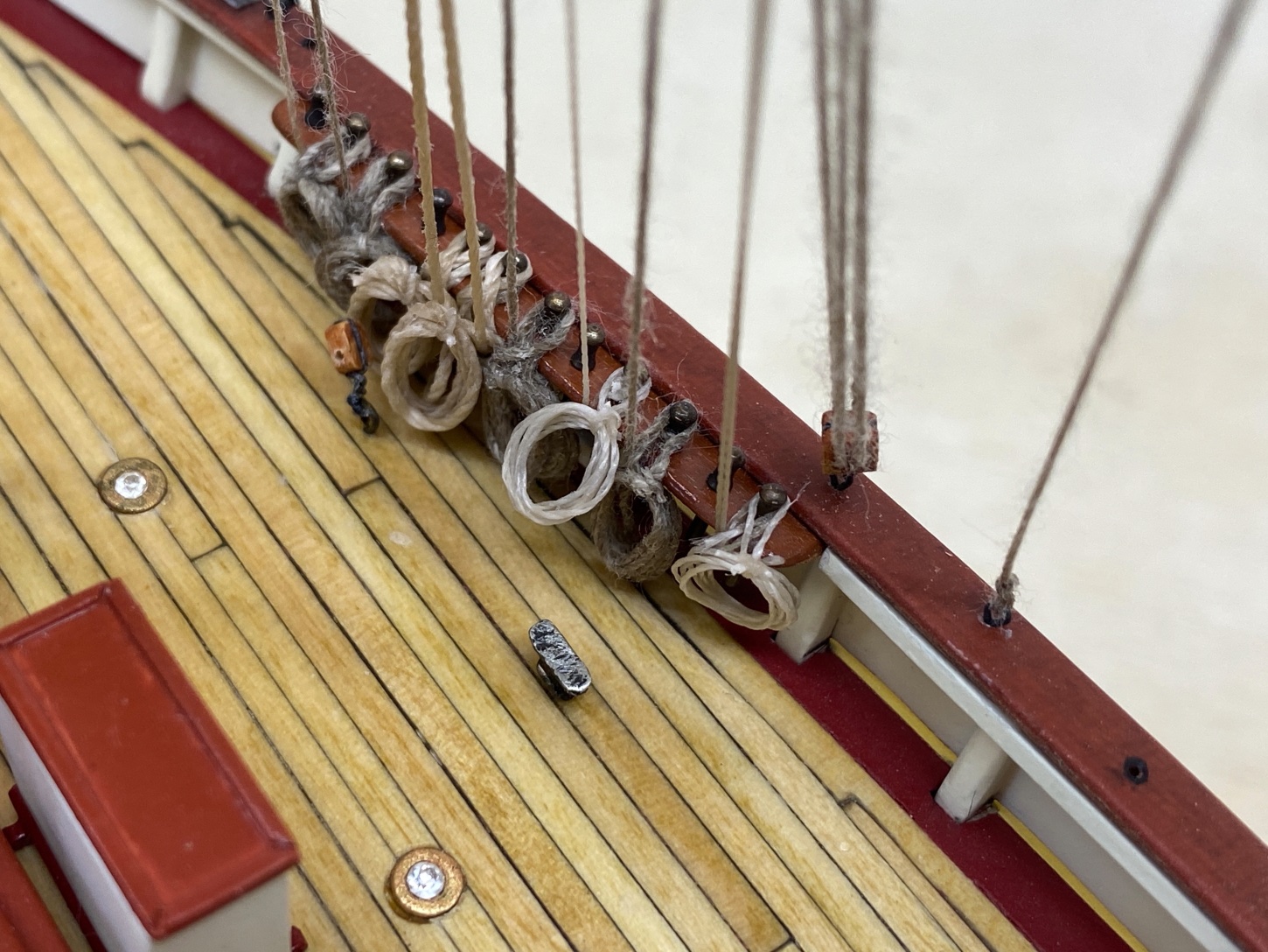
A total of 95 coiled ropes were made. They were installed one by one to their designated belaying pins. Here are some photos.


-
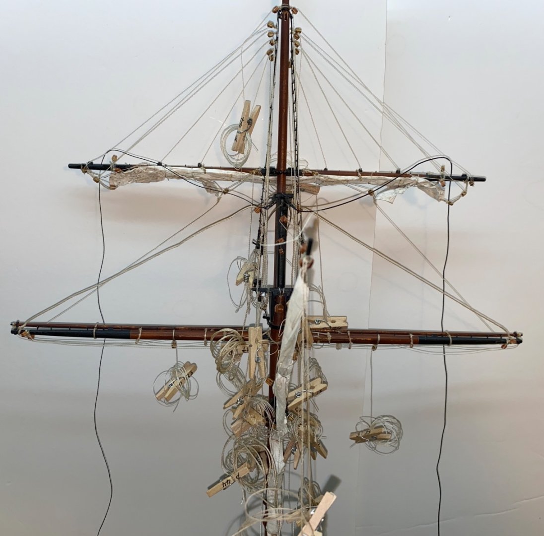
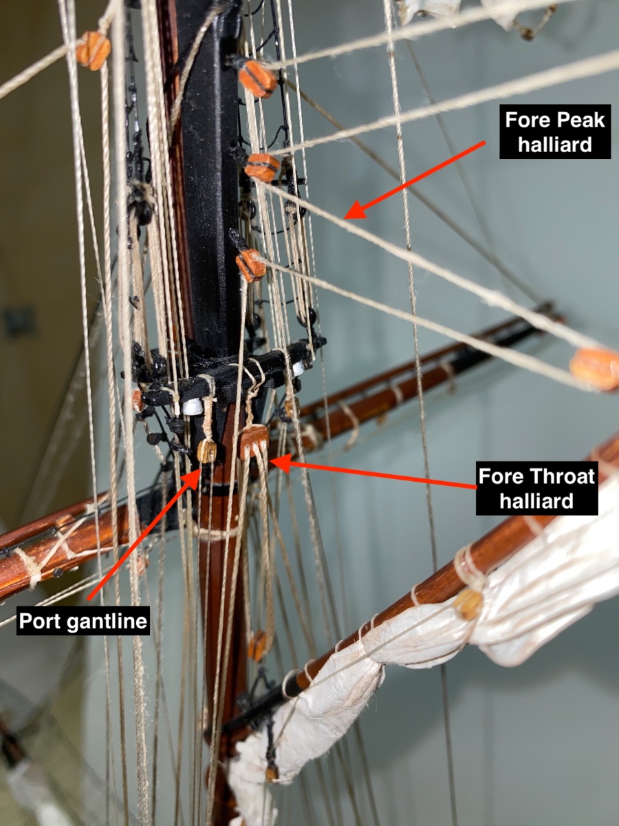
After I finished the installation and furling of the fore sails, I continued with the rest of the rigging.
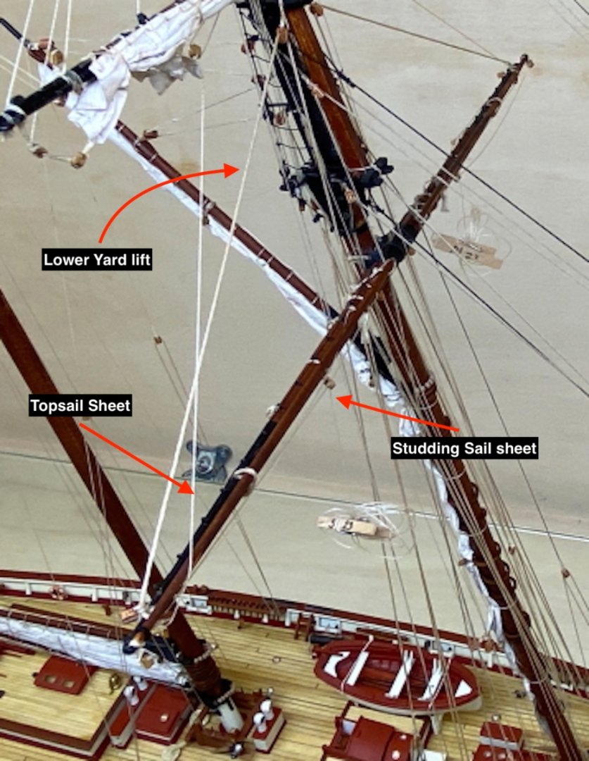
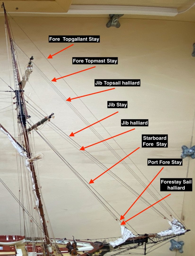
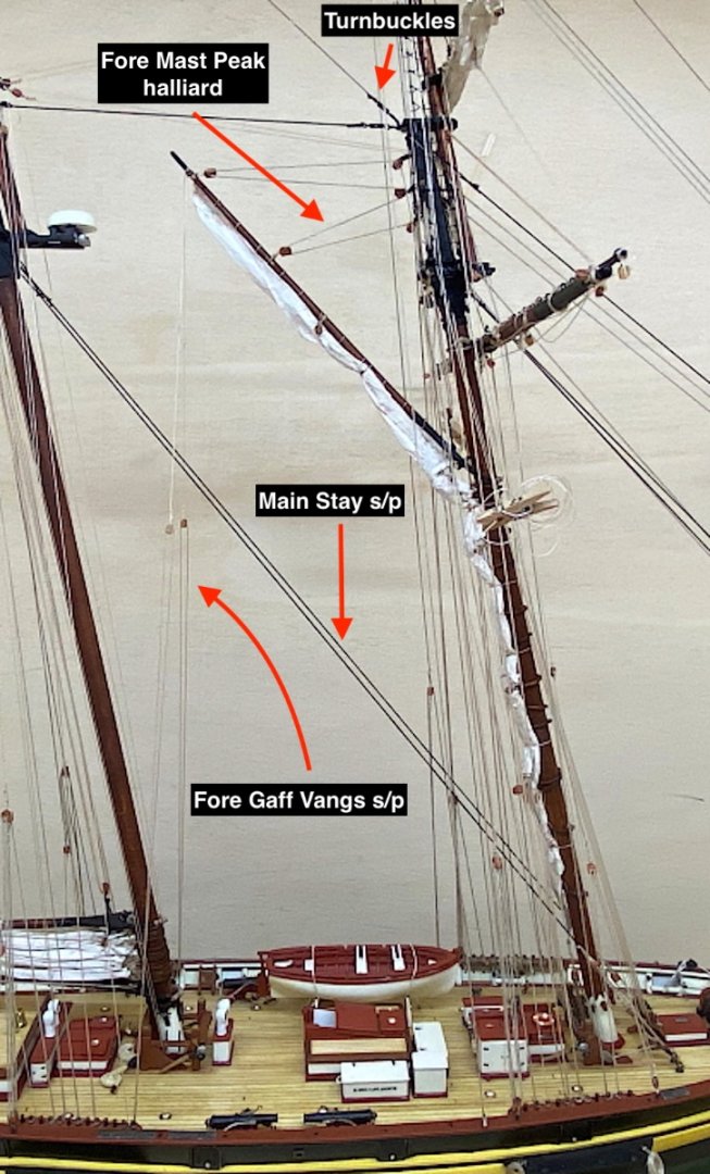
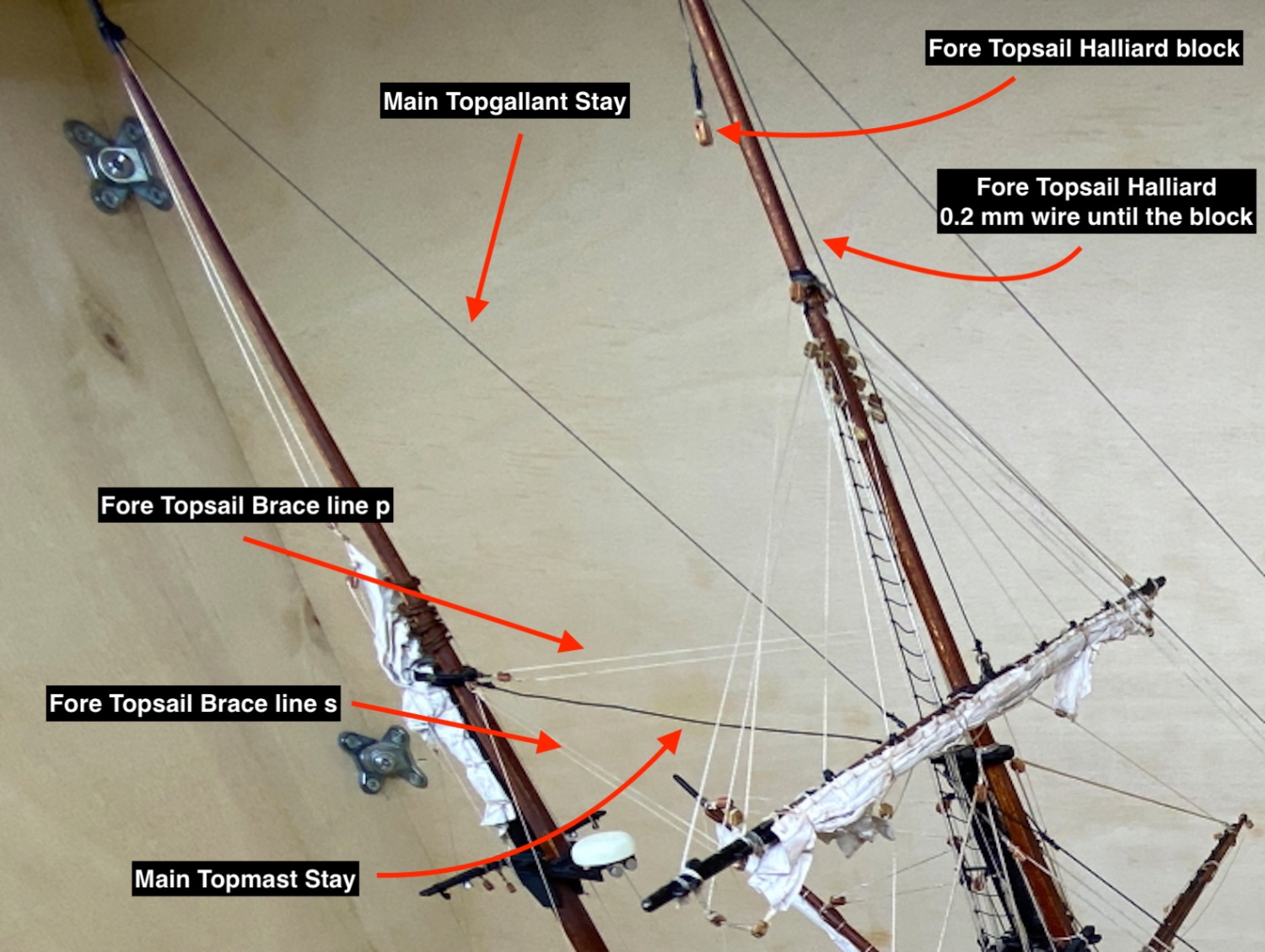
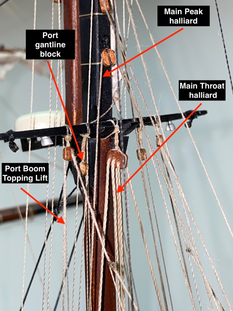
Fore mast rigging was done first. Here you see the photo after the rigging of the fore mast was done. Certain parts of the photo were zoomed in and dissected and some parts of the rigging was named.

Fore Topsail rigging details
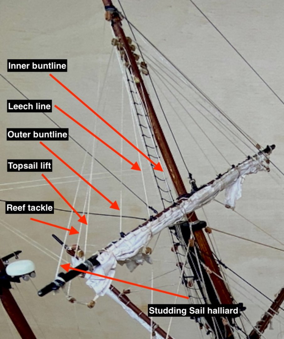
Fore lower yard rigging details
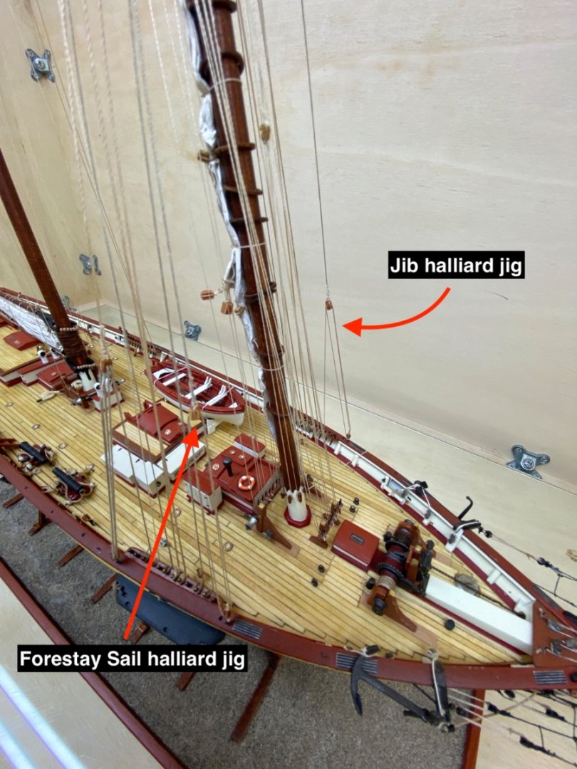
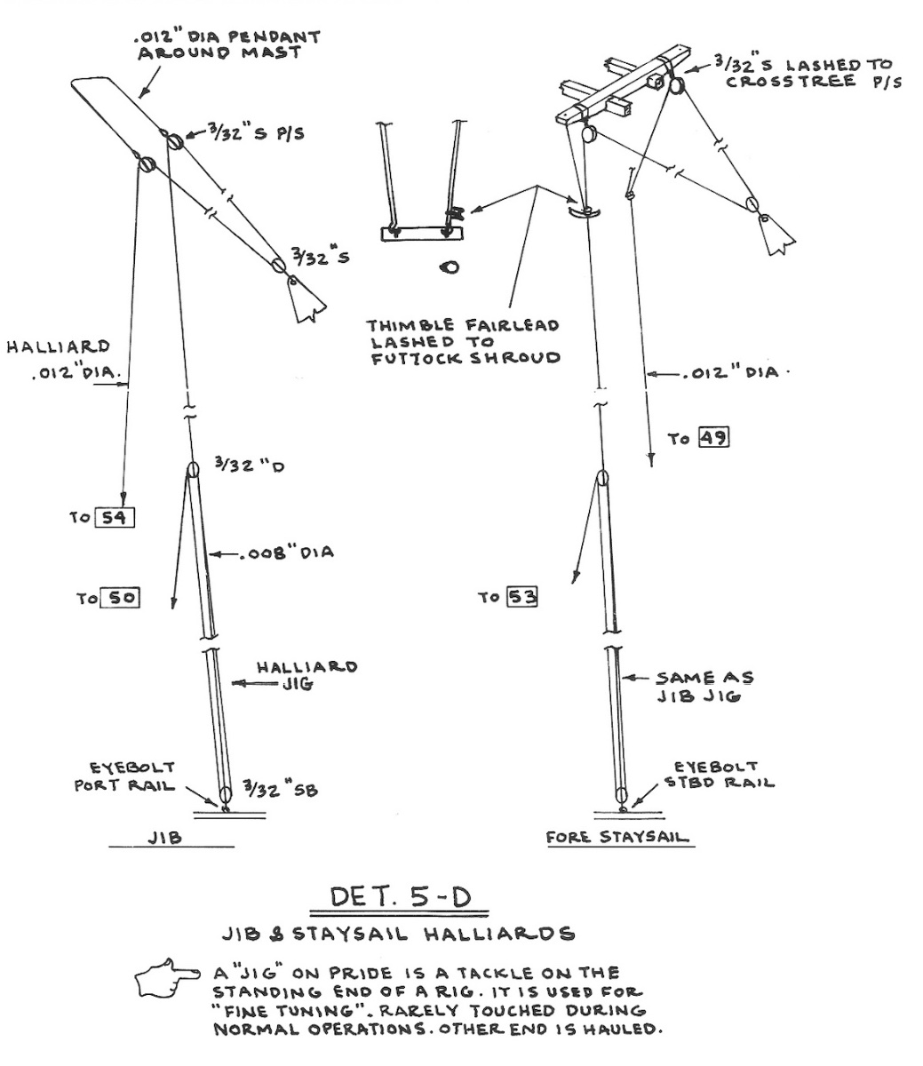
Forestay sail and Jib halliard jigs
Then the rigging of the main mast was done.
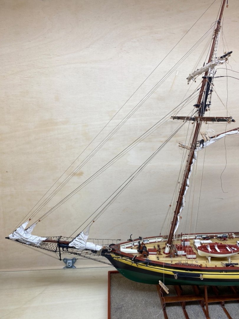
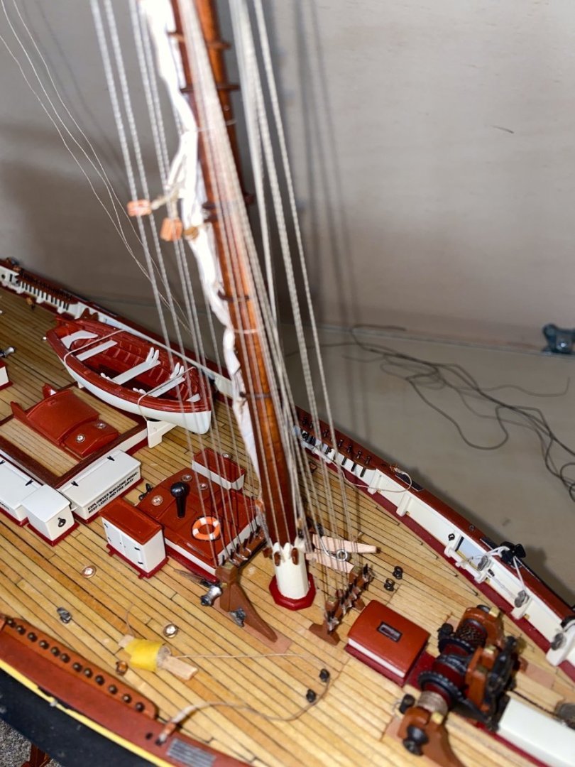
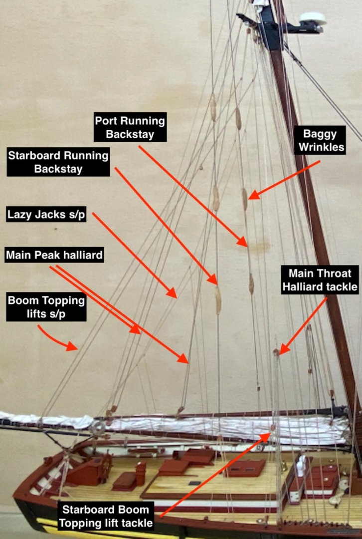 Photos were taken starting from bow to stern both at ground level and later from above with a slight angle.
Starboard side


Port side


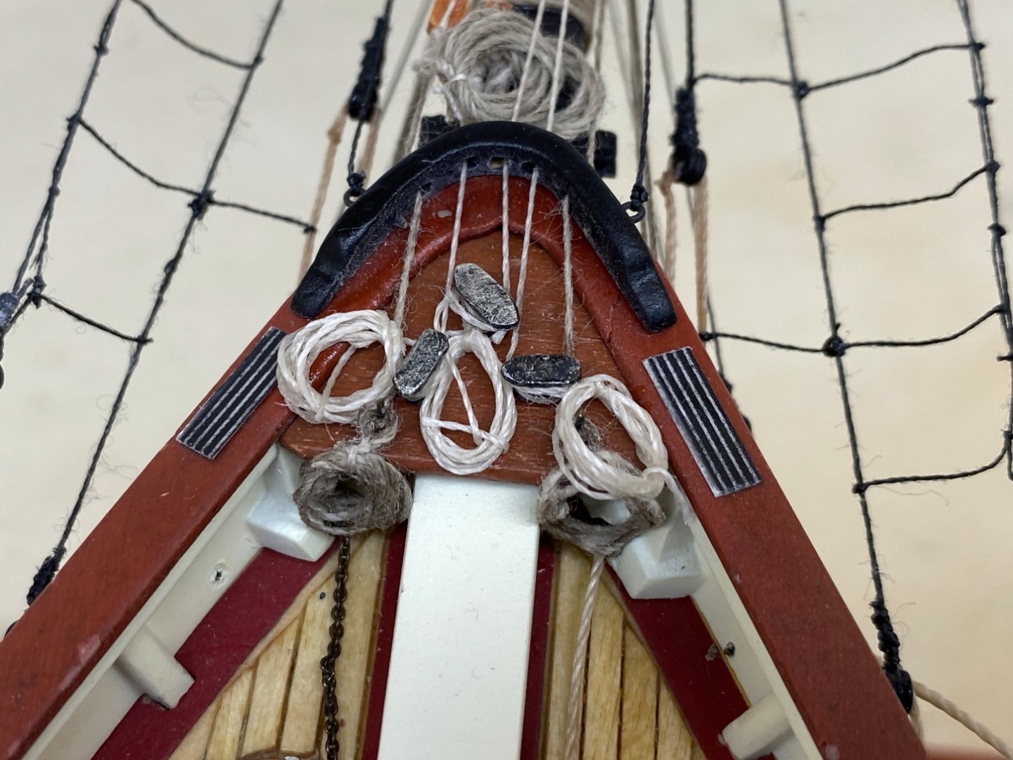
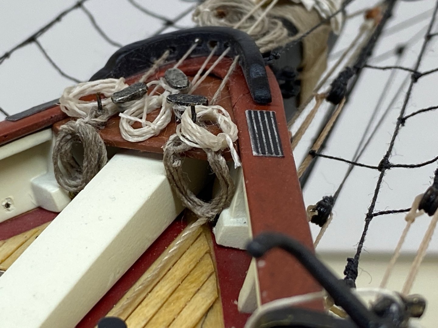
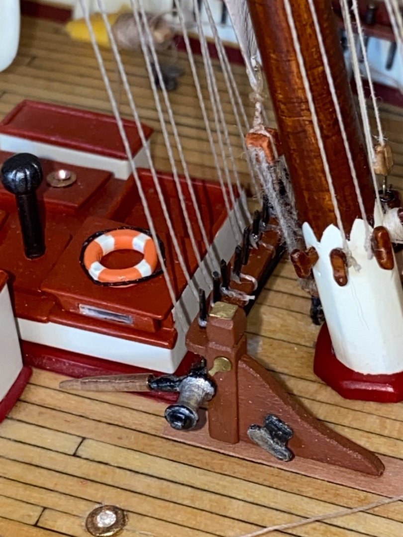
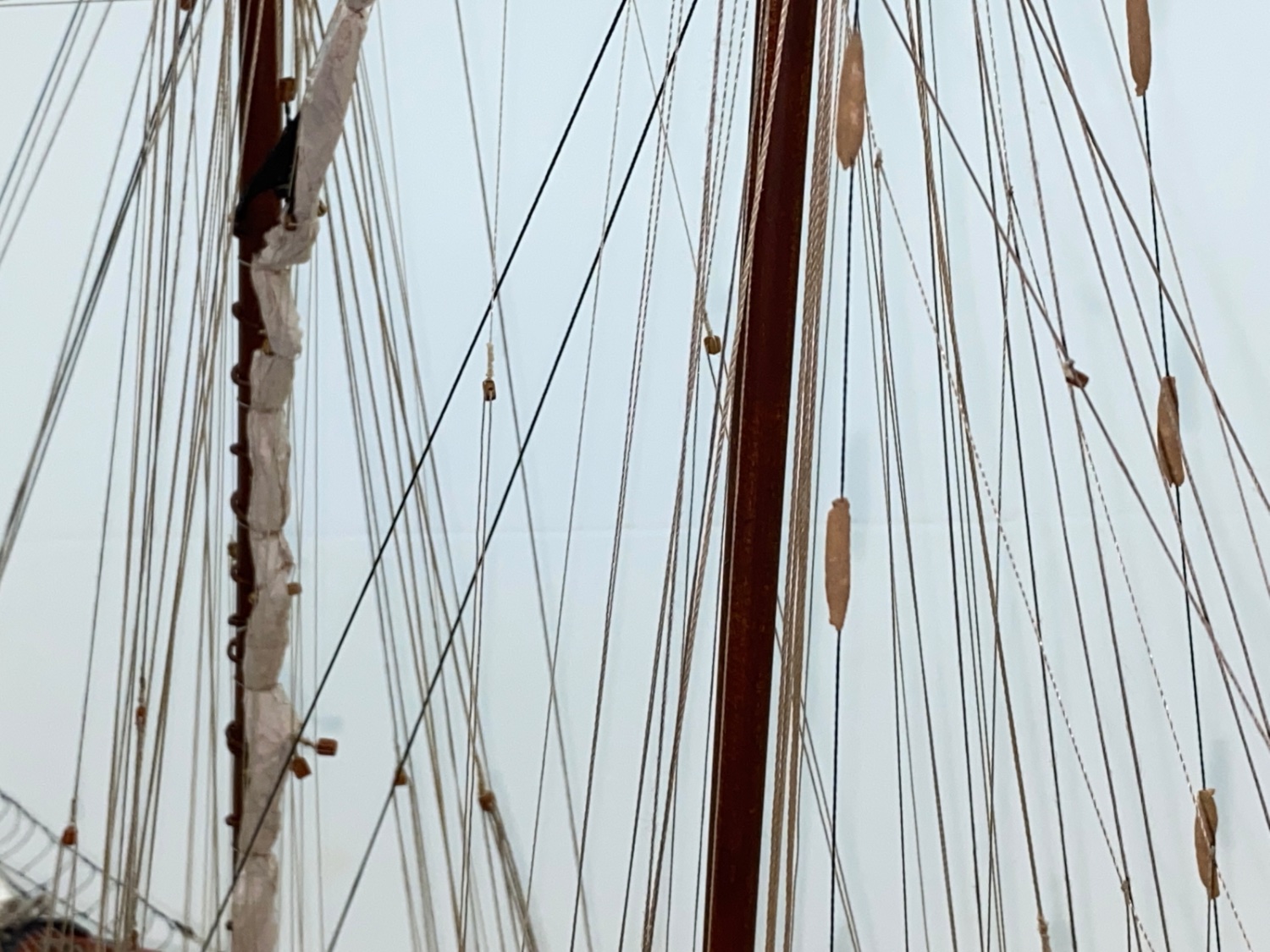
Closeup photos of bowsprit, fore mast and main mast


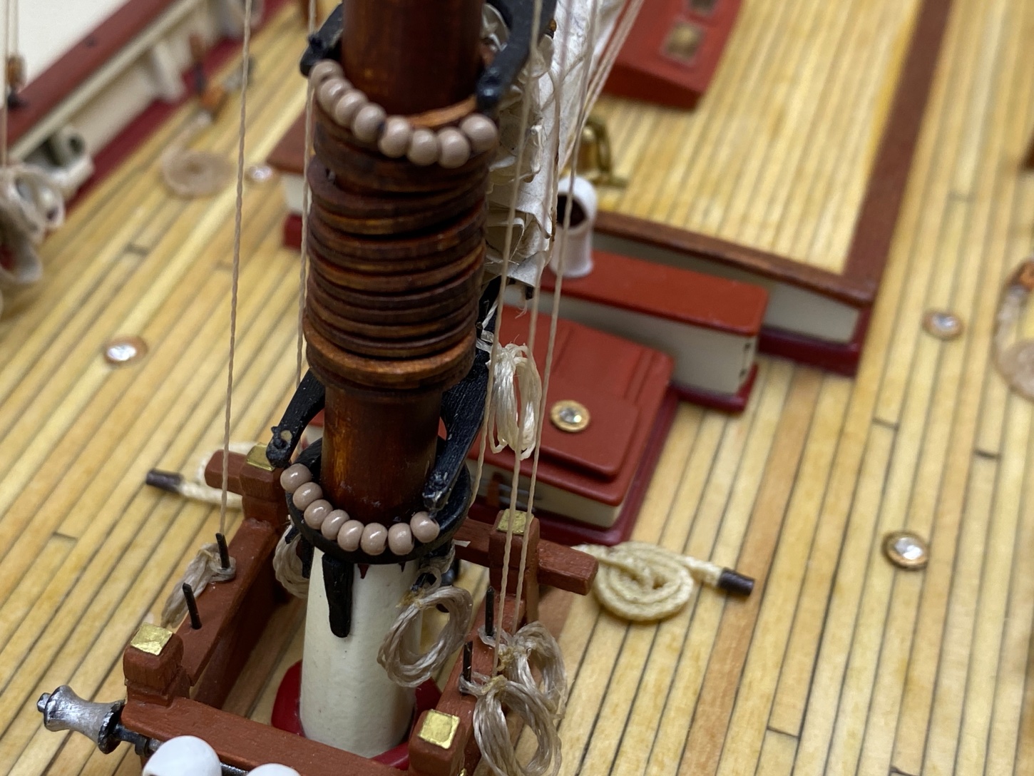
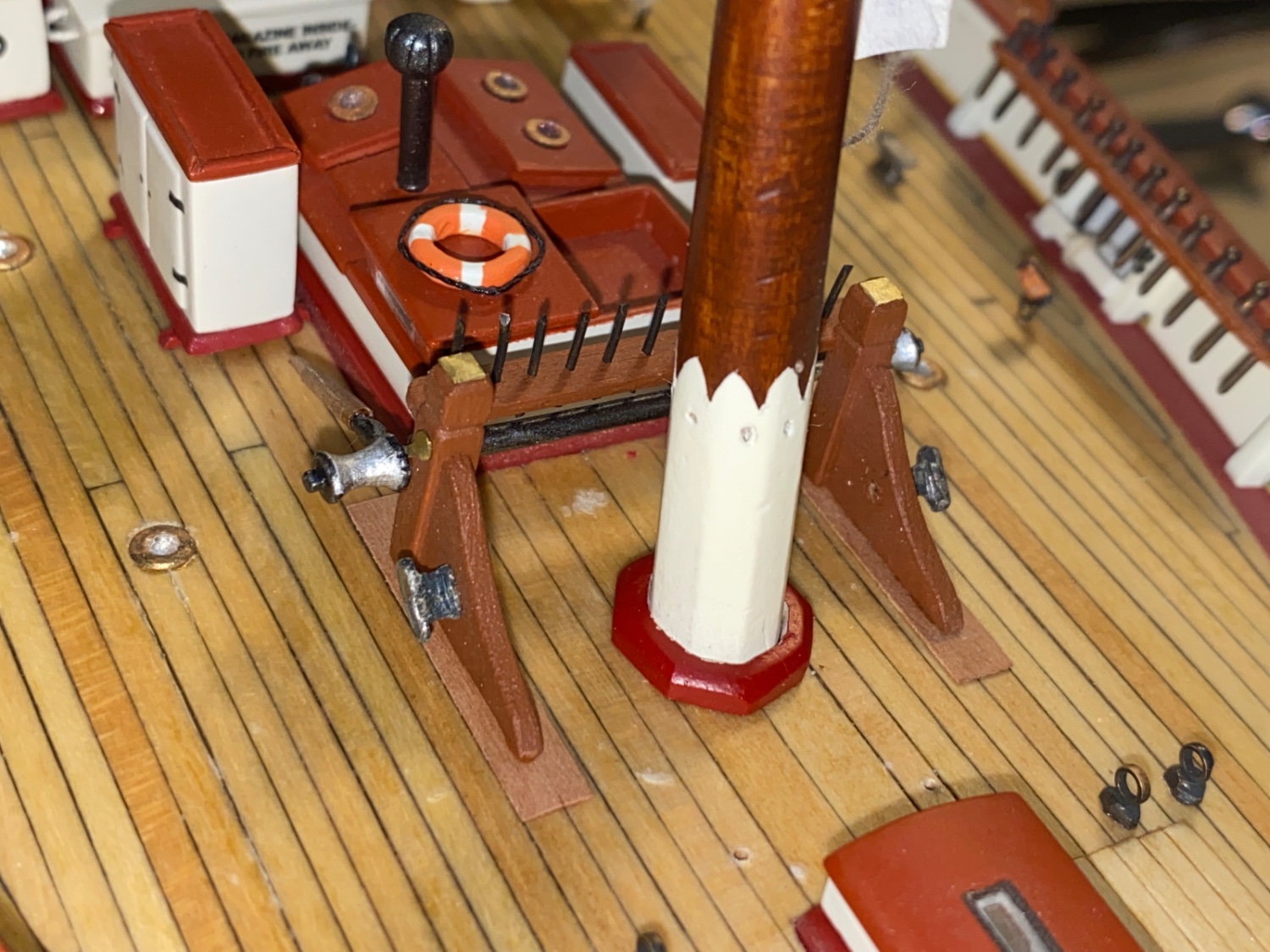
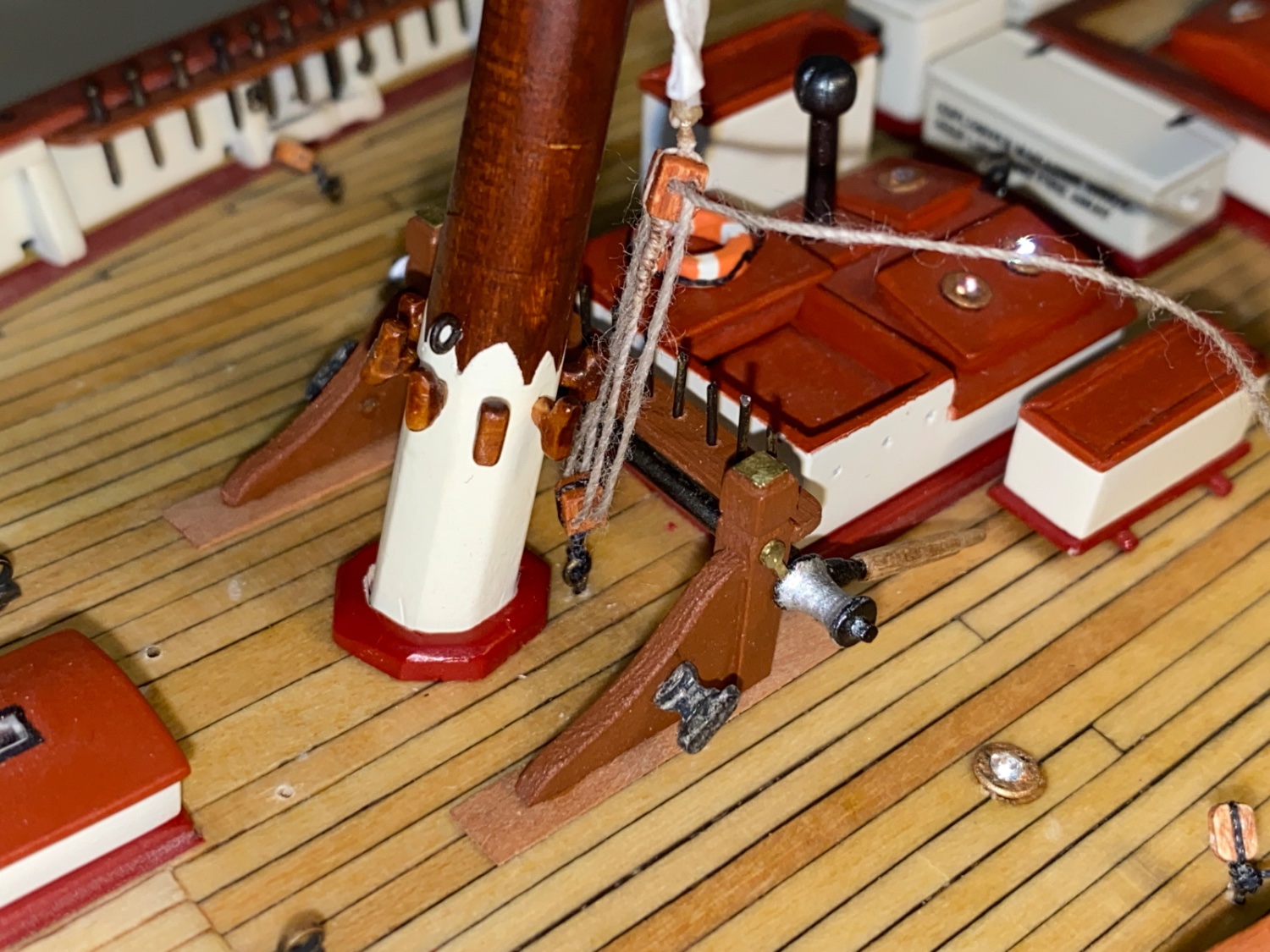
Fore mast base area. Main stay tackles
 Port and starboard blocks of Forestay Sail sheet

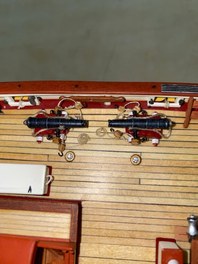
Cannon rigging
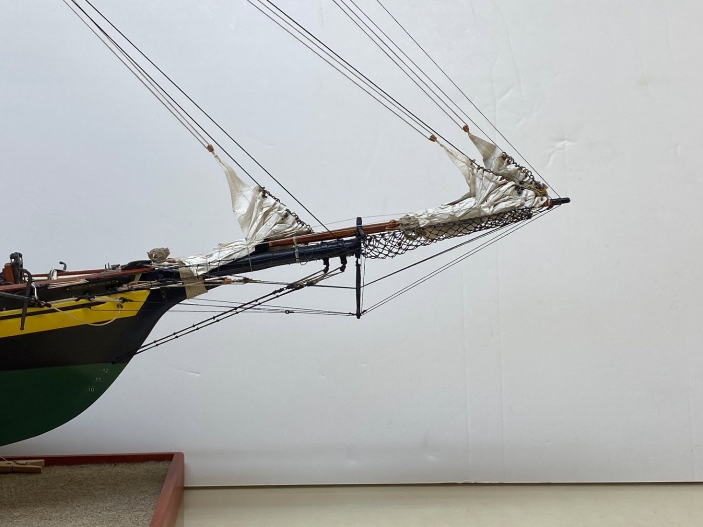
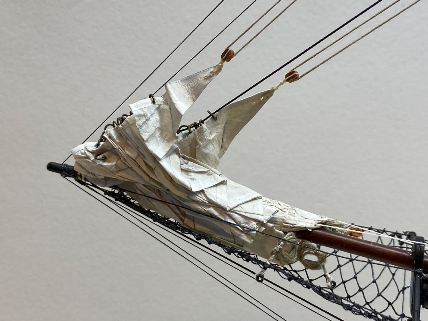
Fore sails and some rigging details of bowsprit and bow cleat and pin platform.


More closeup photos
Fore mast fore to aft view
Fore mast fore to aft view
Fore mast aft to fore view

Main mast aft to fore view
The photo of the port fore pin rail platform. This platform has a sad story. When I was rigging the standing lines of the fore mast and applying a little bit more force in order to correct the misalignment of the fore and main masts, this platform snapped off. As a lot of lines were belayed to its pins at that time, I had to reglue and replace the platform with them attached. As expected the result was not like the other three and inboard free side of the platform was a little bit elevated and pointing upwards. They say lightening does not strike twice at the same point ! Ha ha ha....
When I was busy with the main mast rigging on port my left hand hit the belayed and taut lines at the poor platform and it snapped off AGAIN..
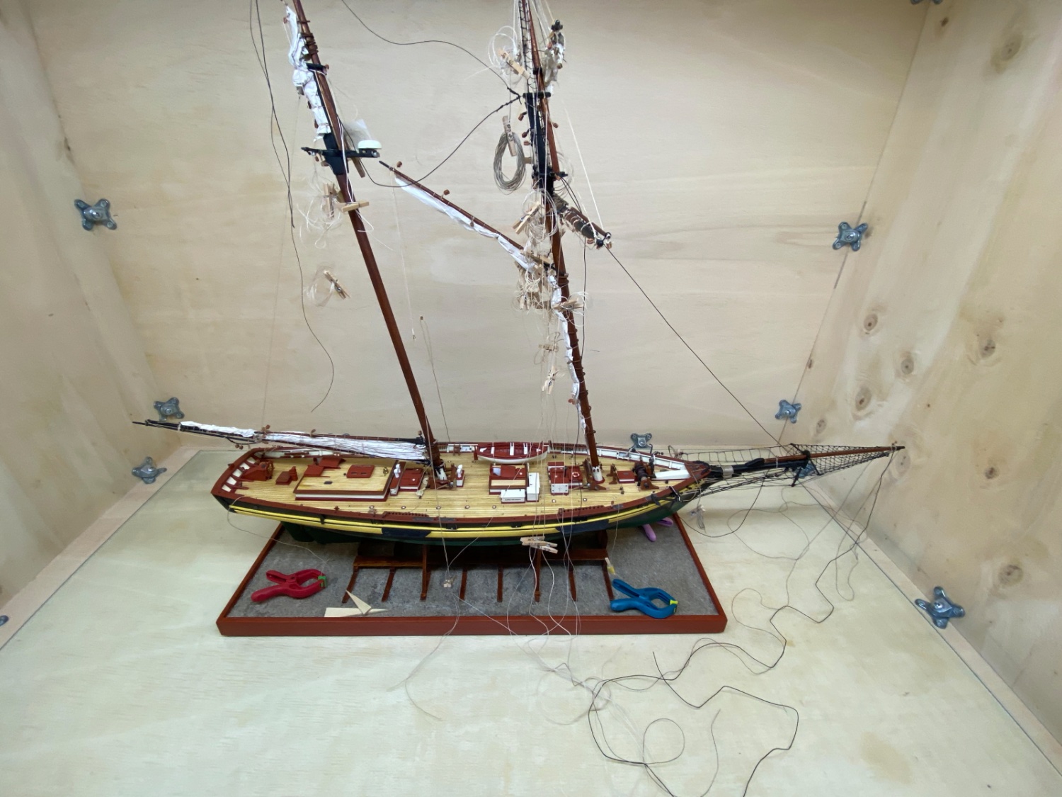
And the final photo of the post. A chaotic but organized rigging lines almost like puzzle...
- Prowler901, ccoyle and yvesvidal
-
2
-
1
-
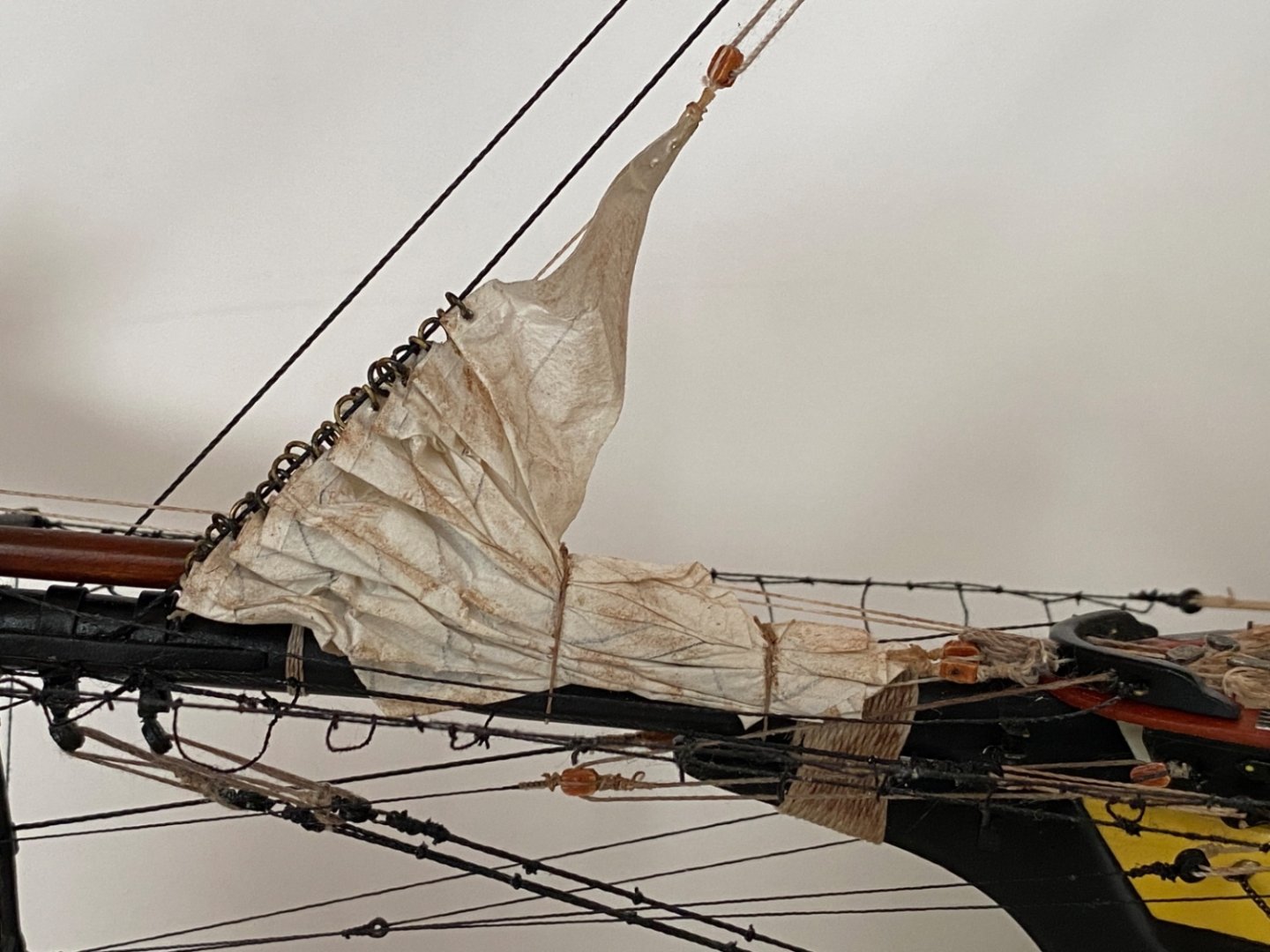
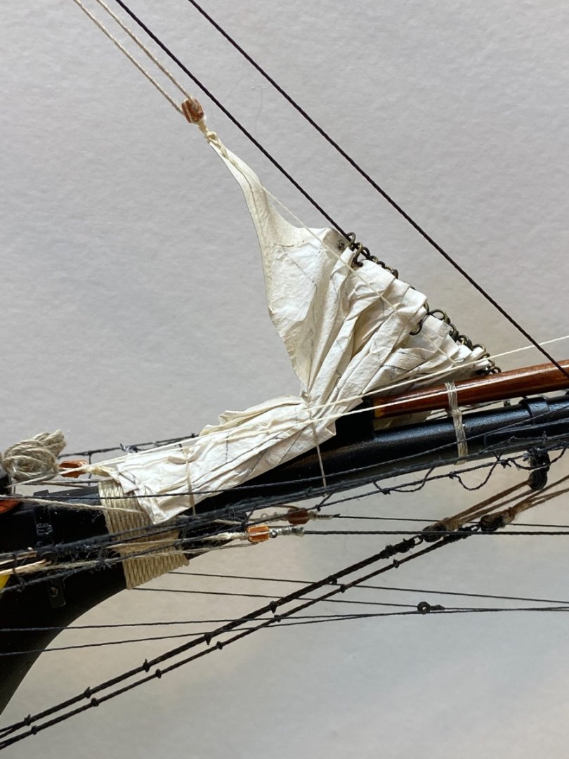
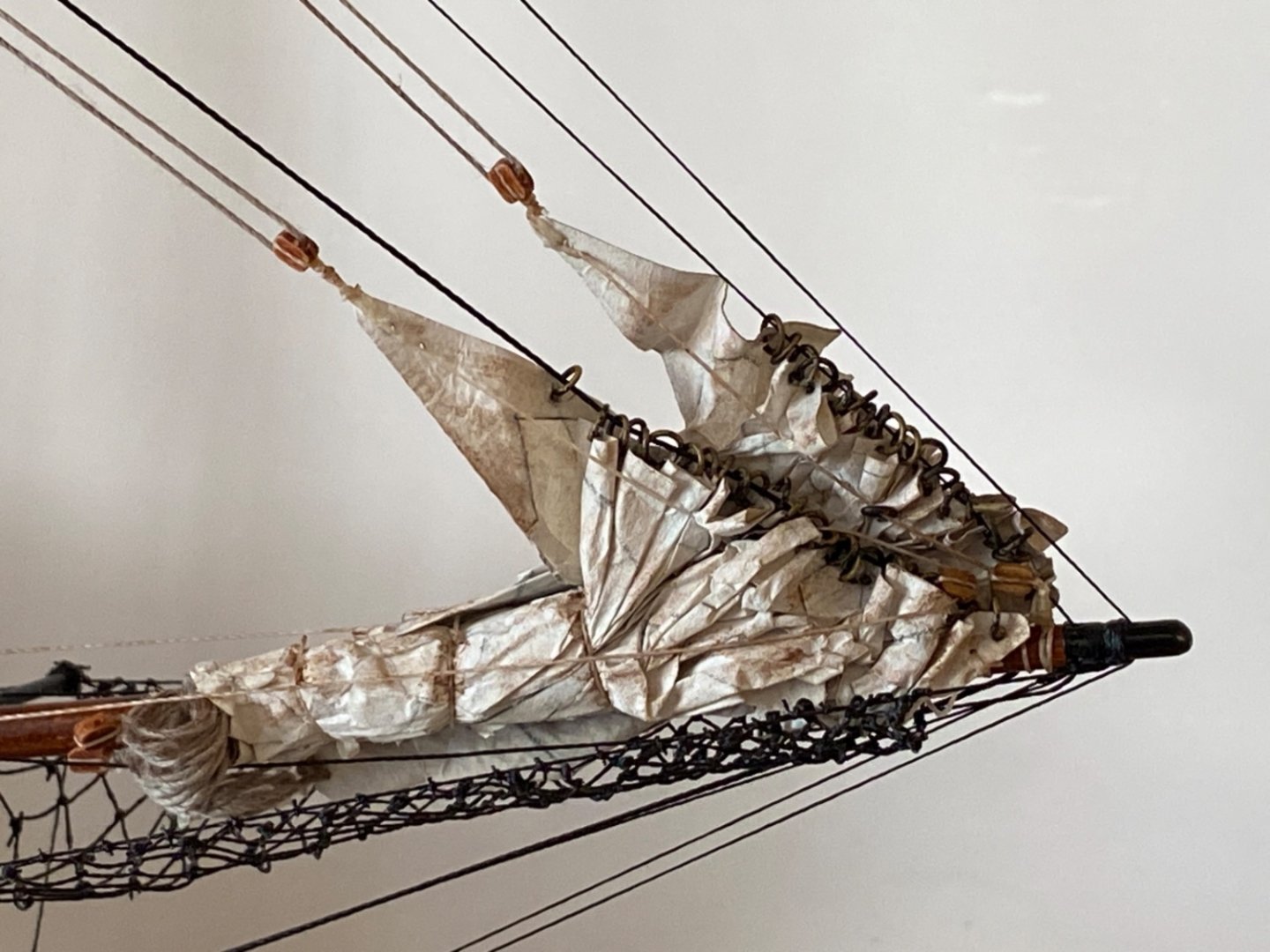
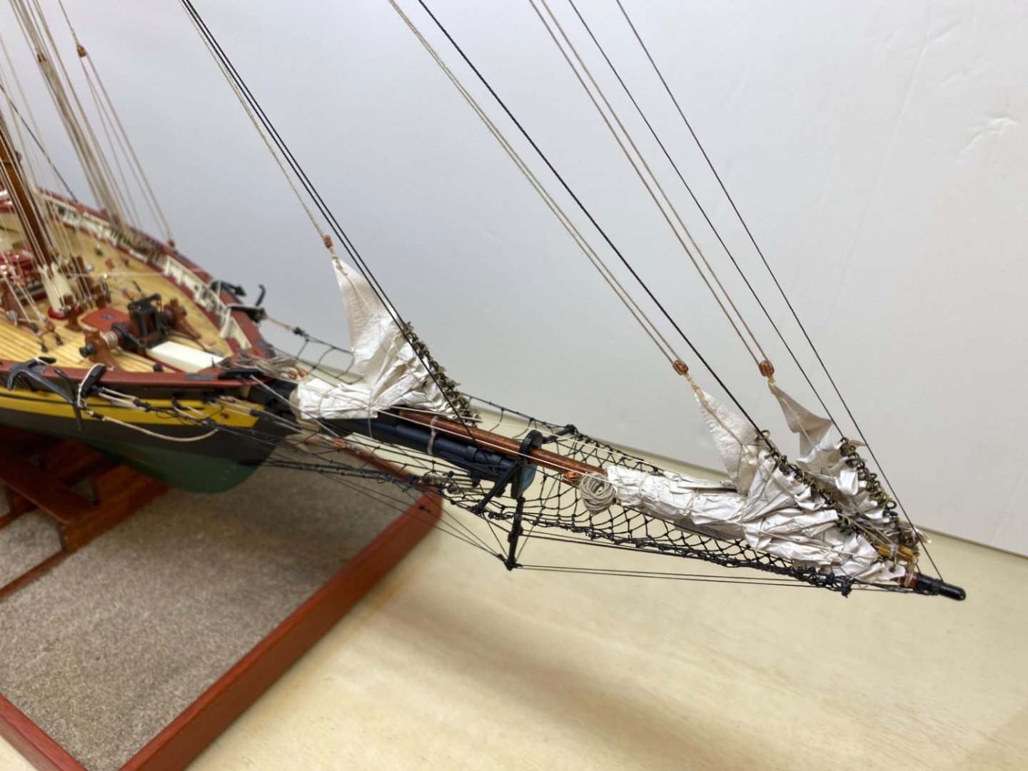
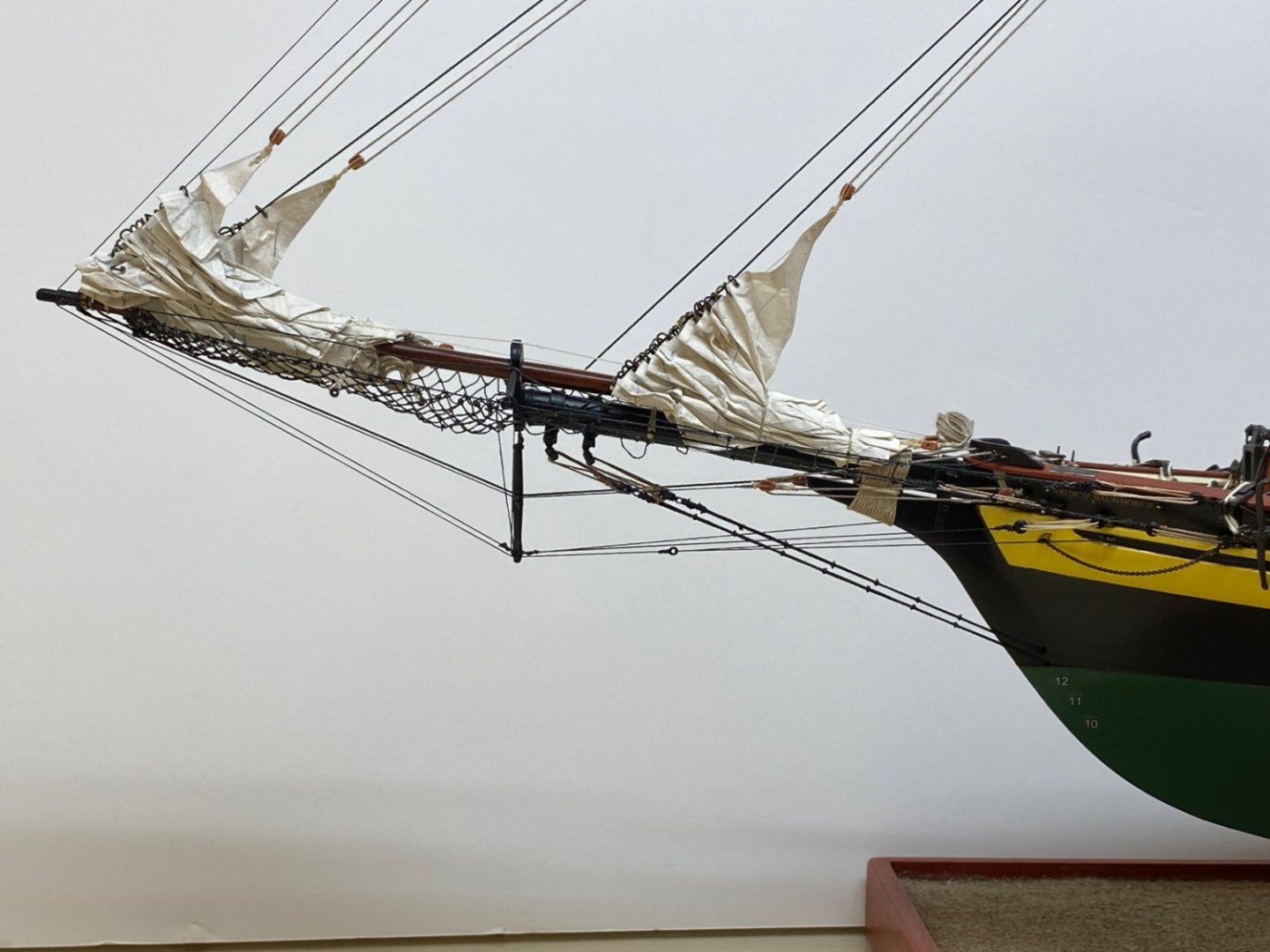
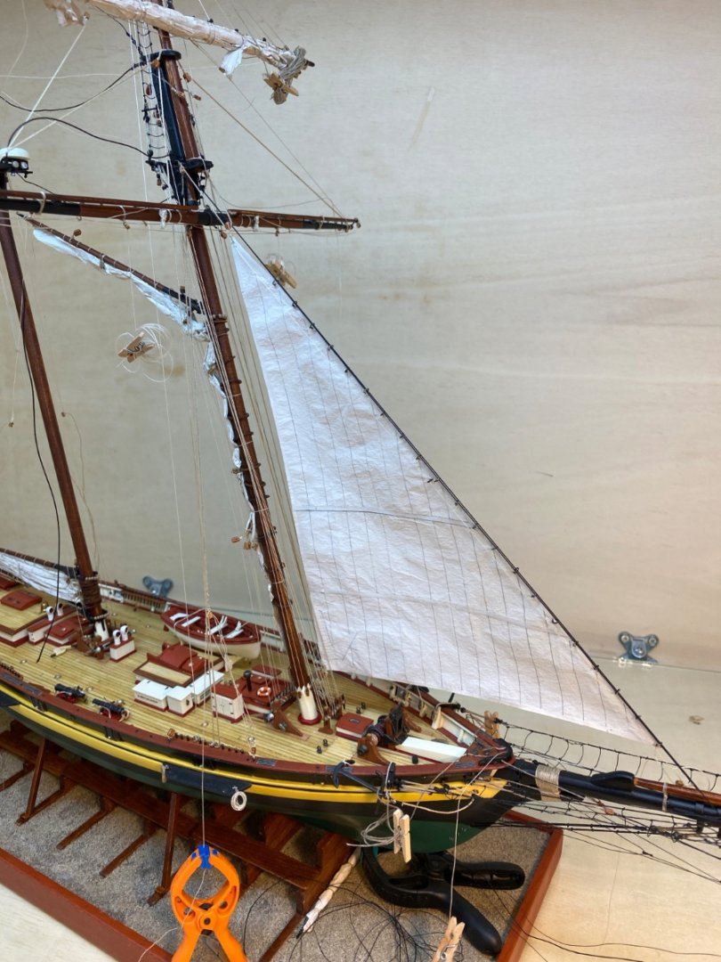
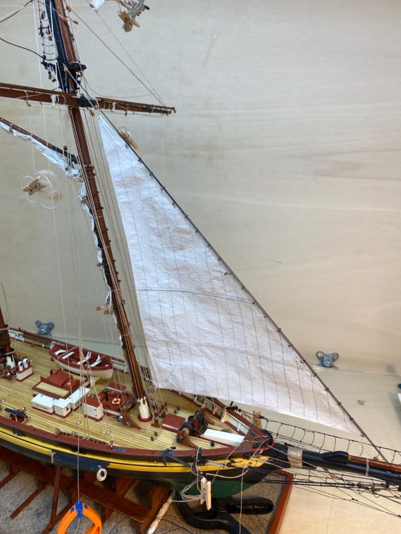
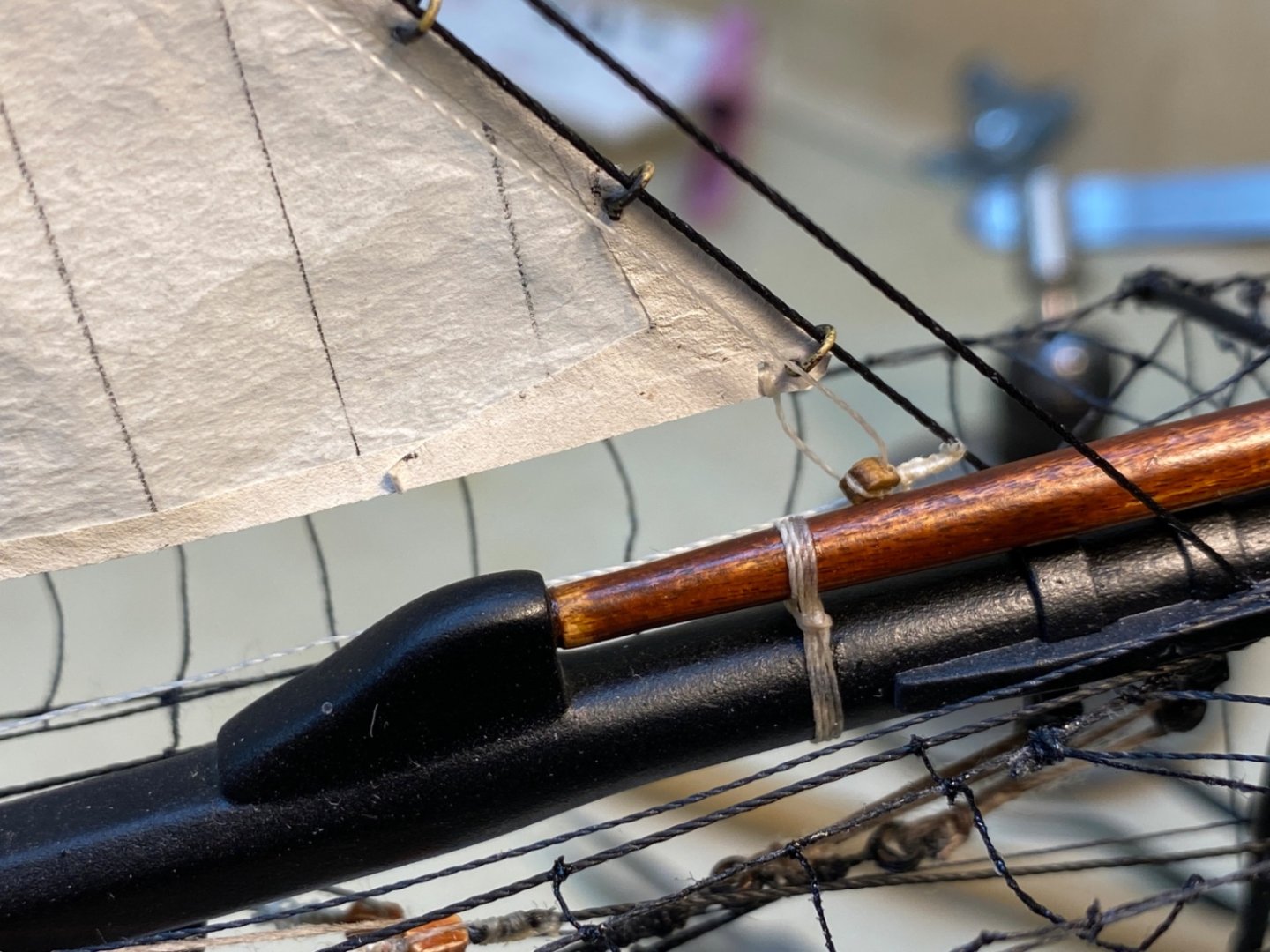
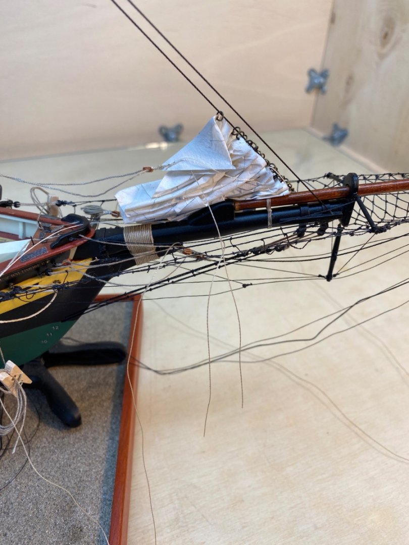
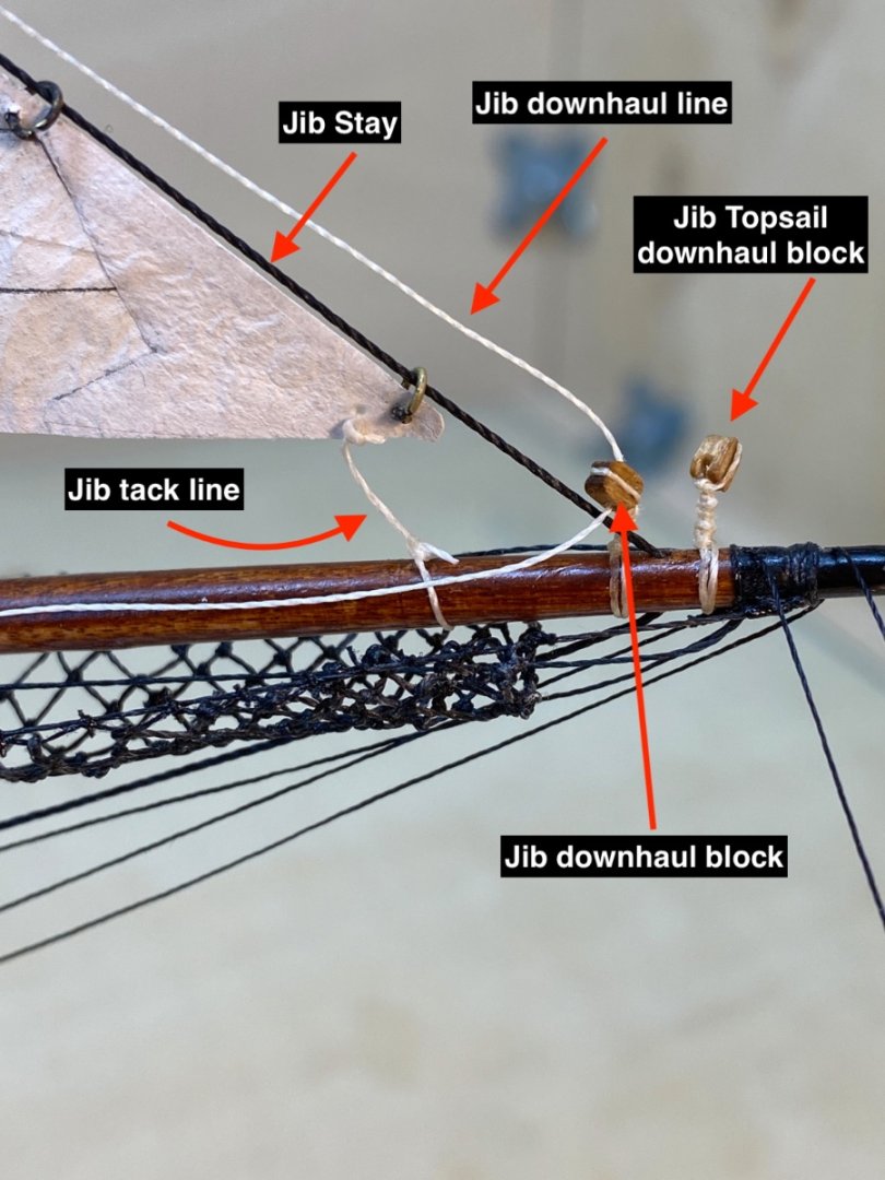
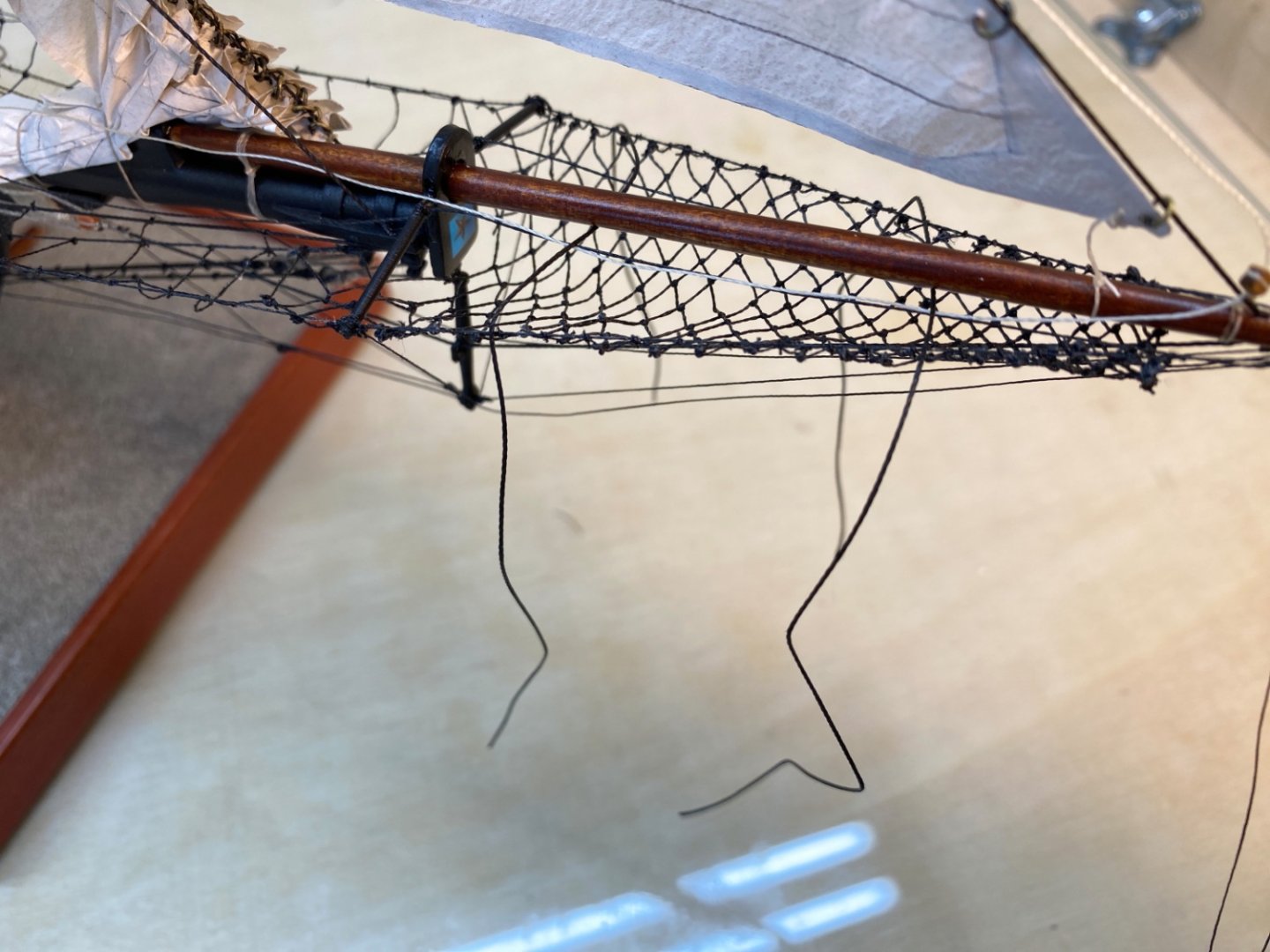
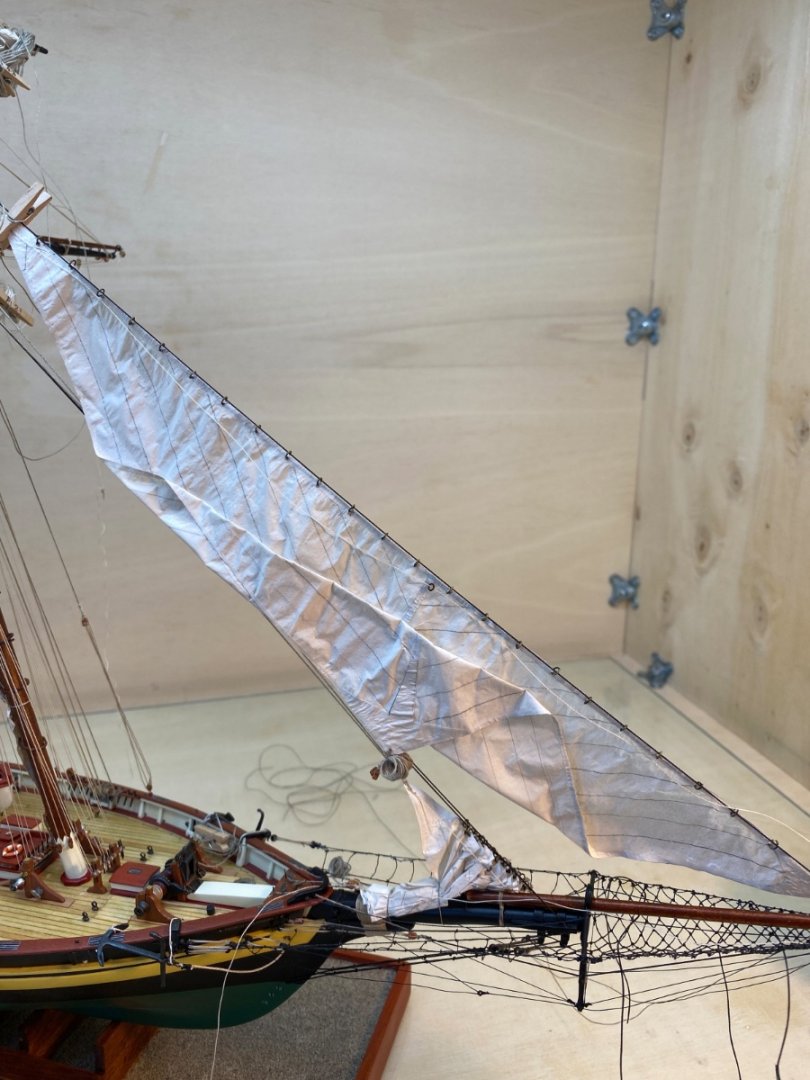
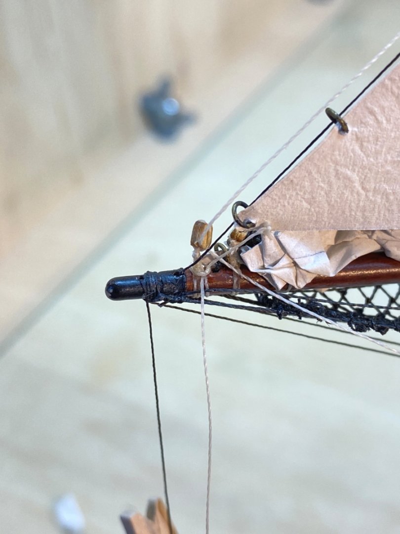
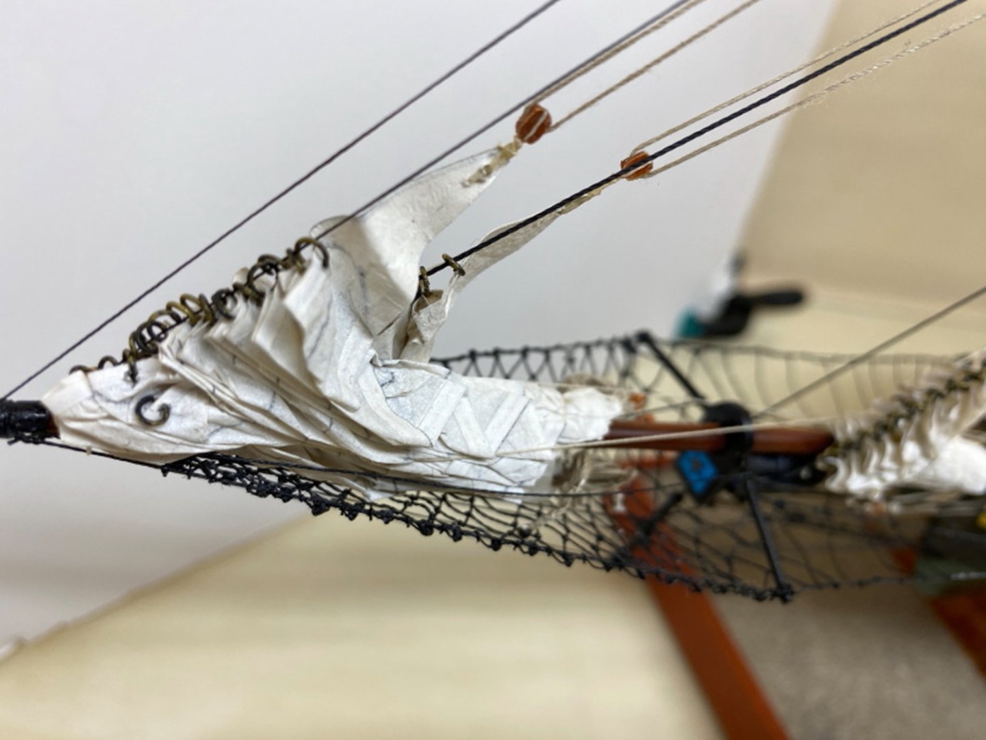
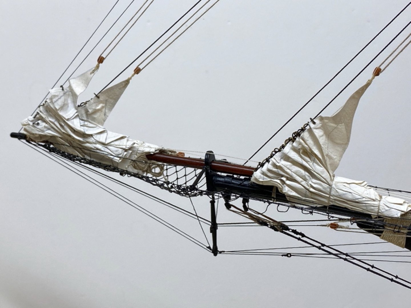
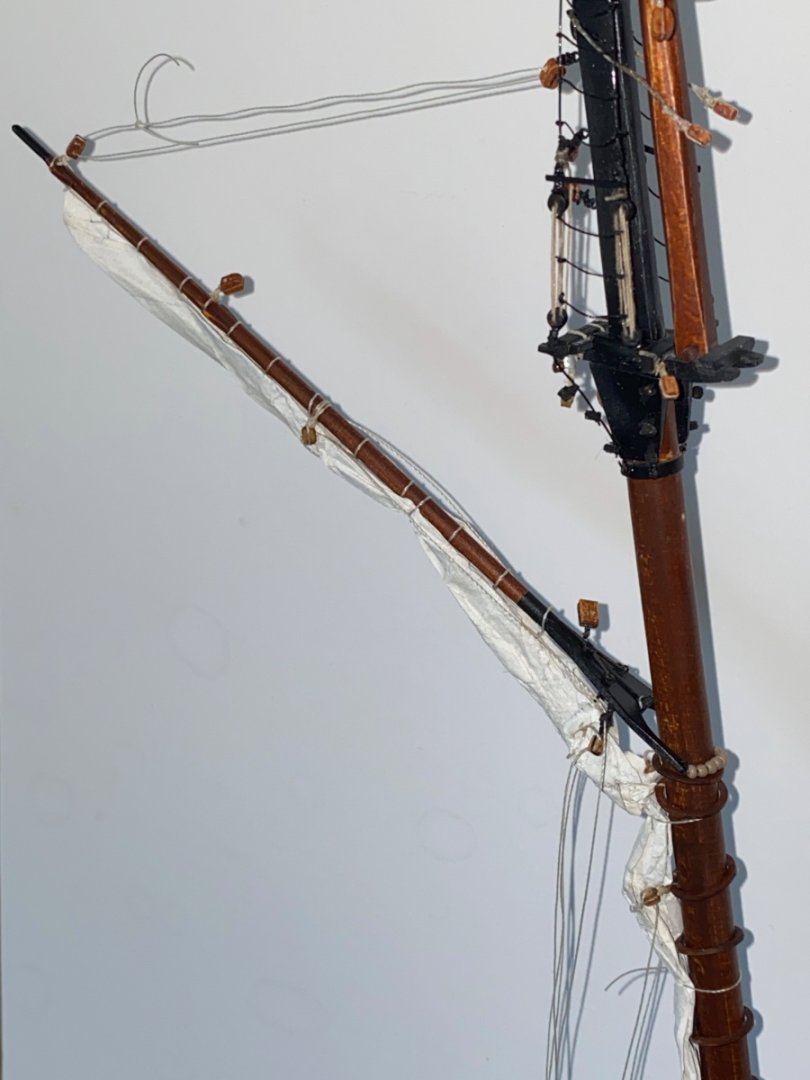
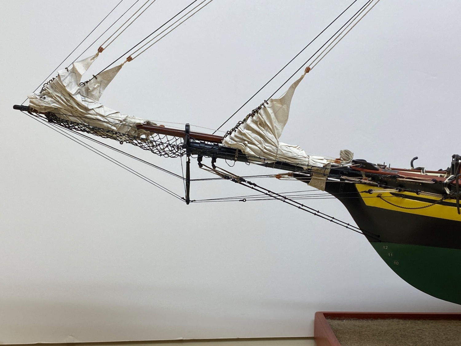
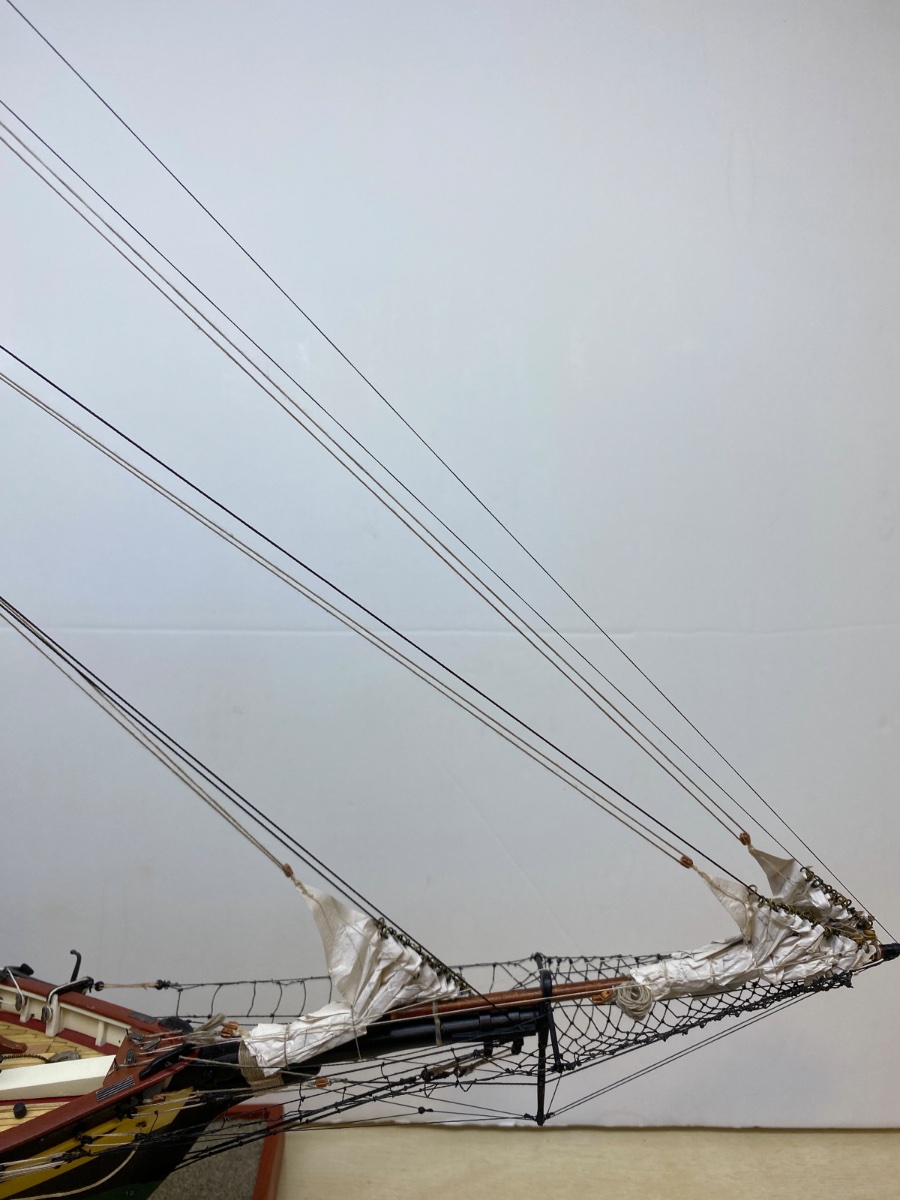
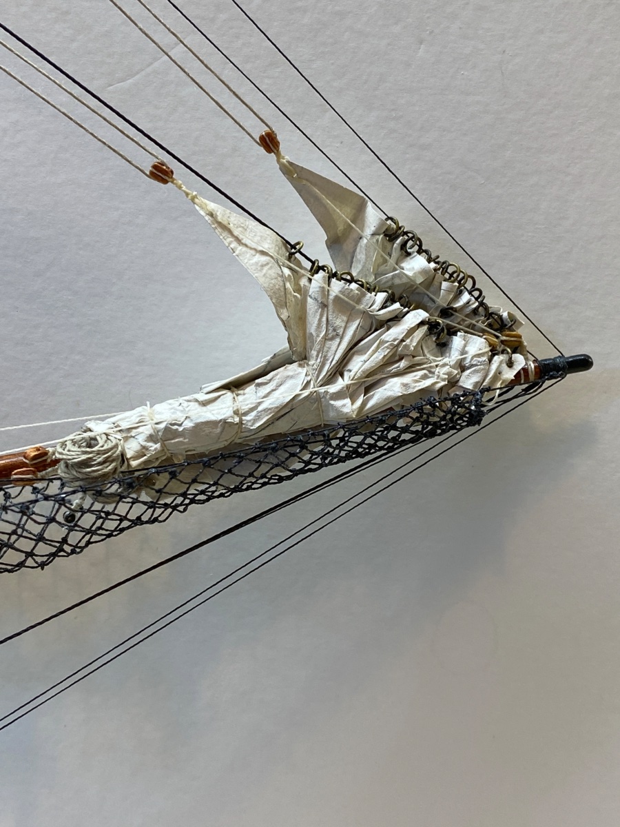
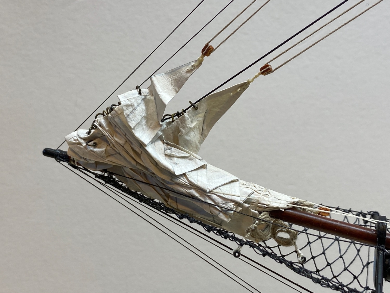
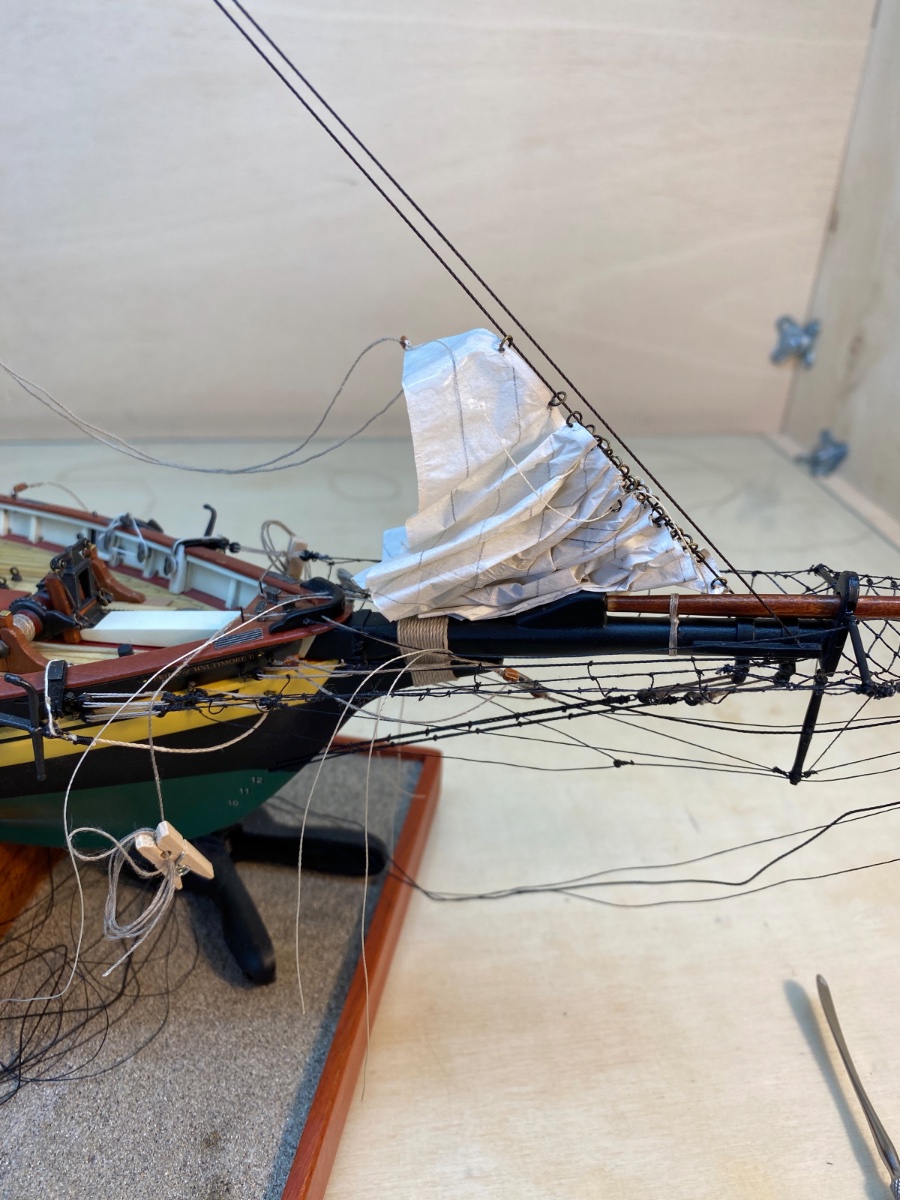
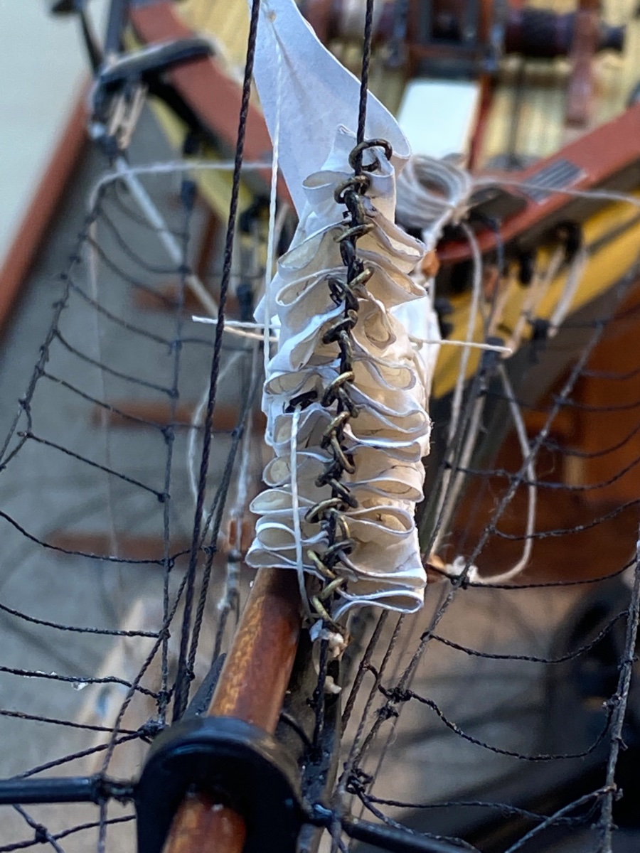
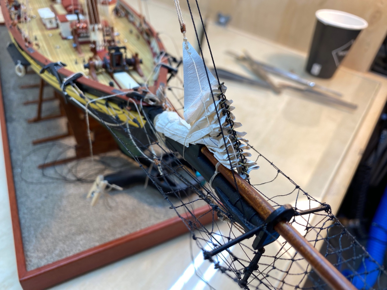
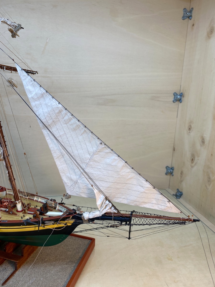
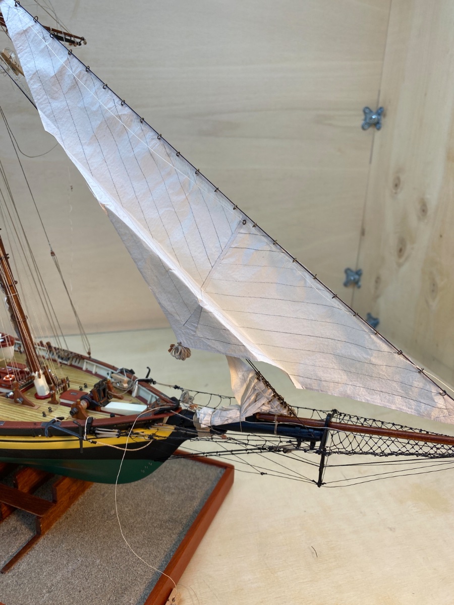
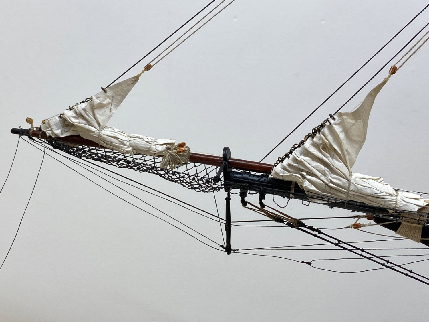
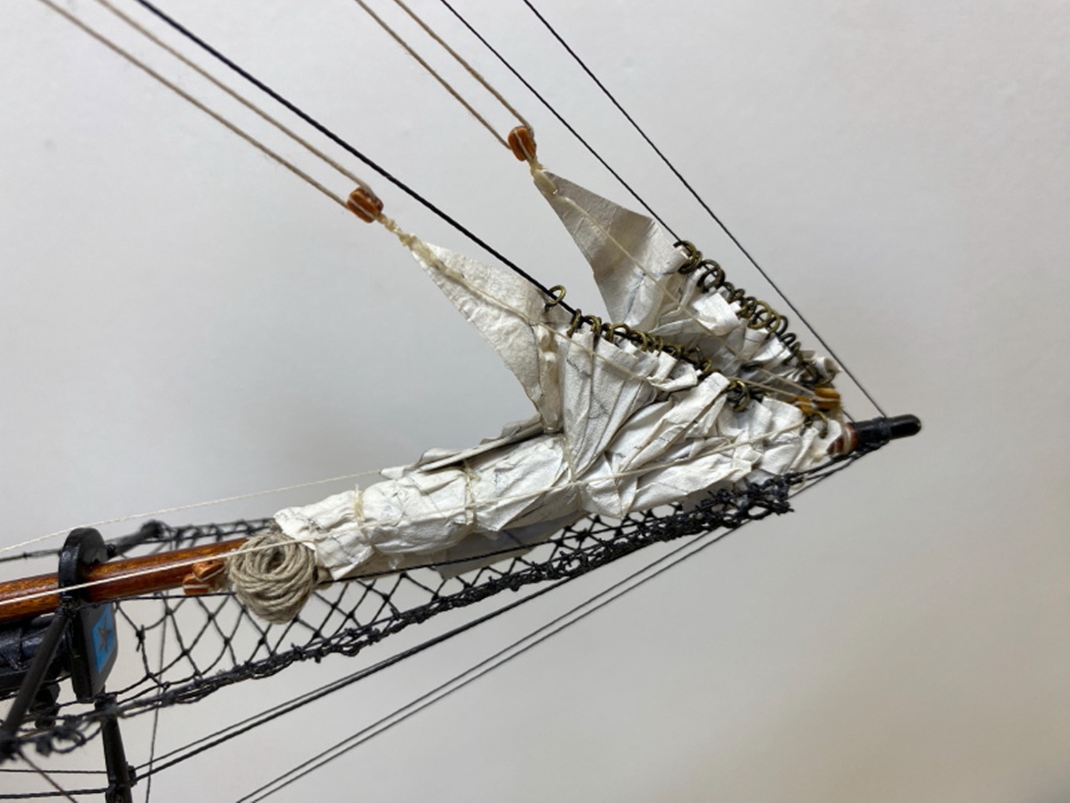
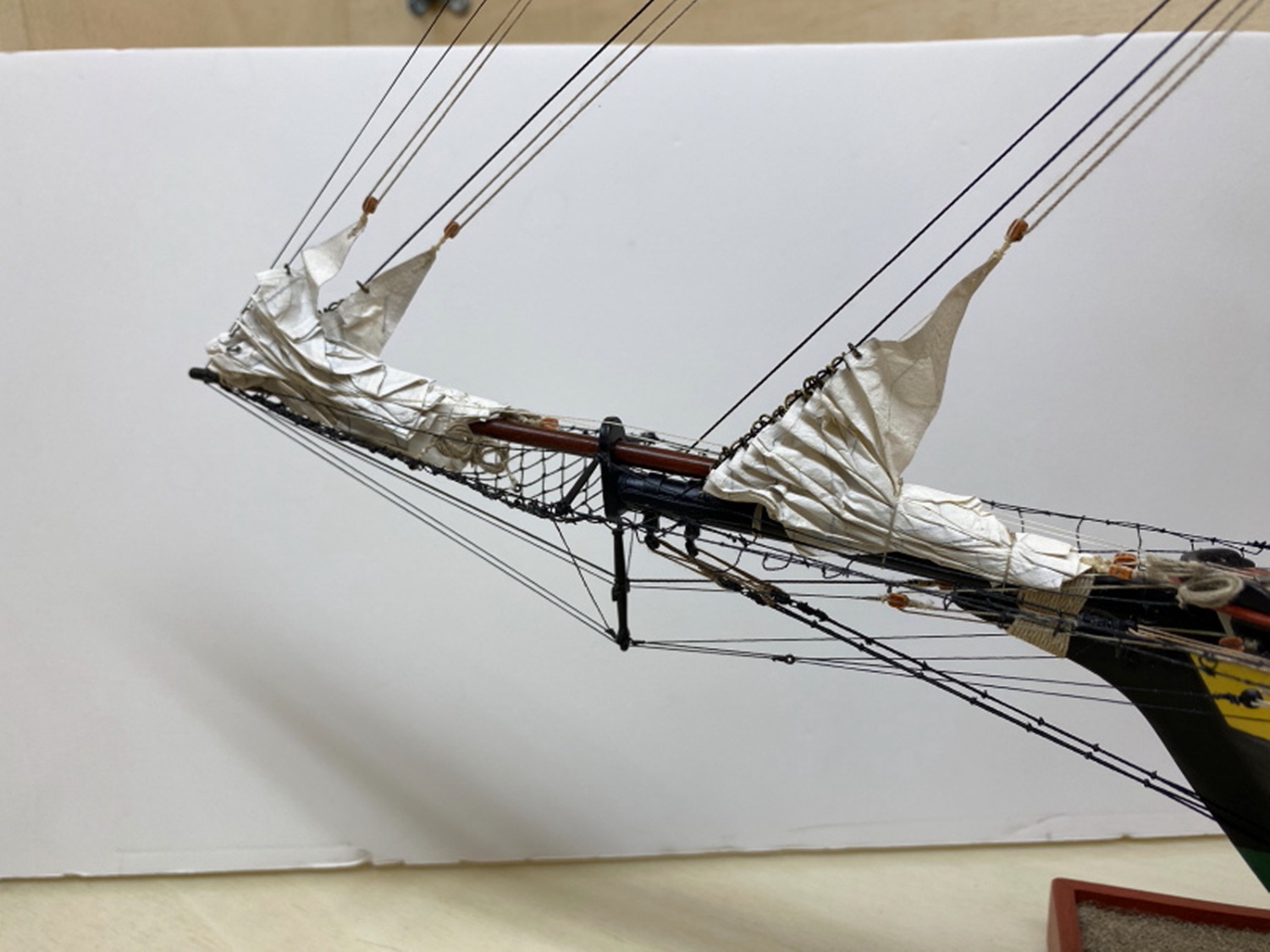
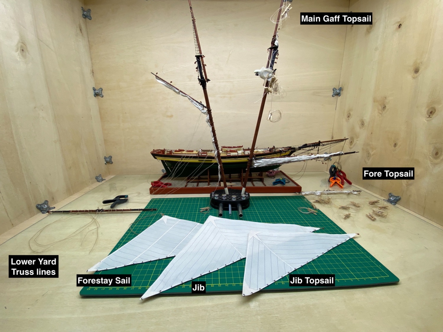
The next step was the installation and furling of the fore sails. There are three fore sails : Forestay sail, Jib and Jib Topsail. They are seized to port Fore Stay, Jib Stay and Fore Topmast Stay respectively . Forestay Sail and Jib halliards have special tackles called jigs. Jib Topstay halliard is just like Main Gaff Topsail halliard and its halliard line is seized to fore topmast just under the sheave, reeved through the block at the head and later through the topmast sheave. Here is the photo of the Forestay Sail and Jib halliards from the plan.

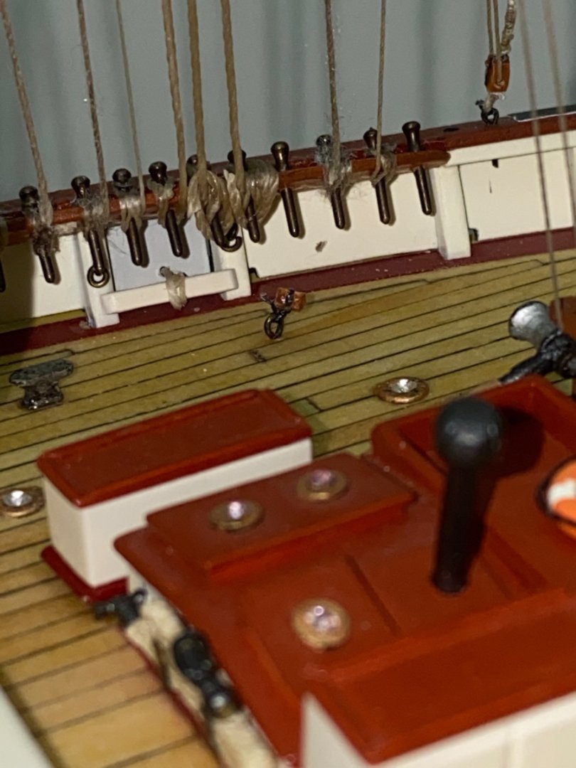
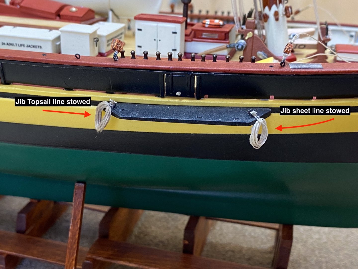
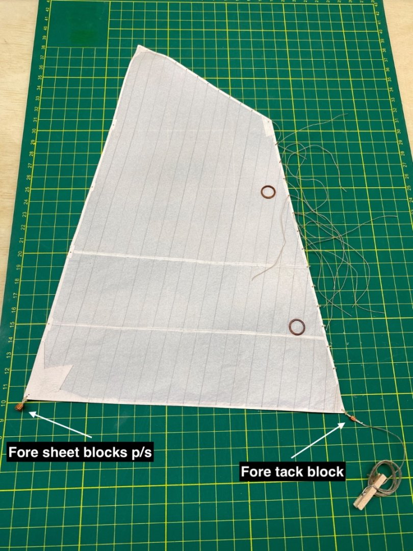
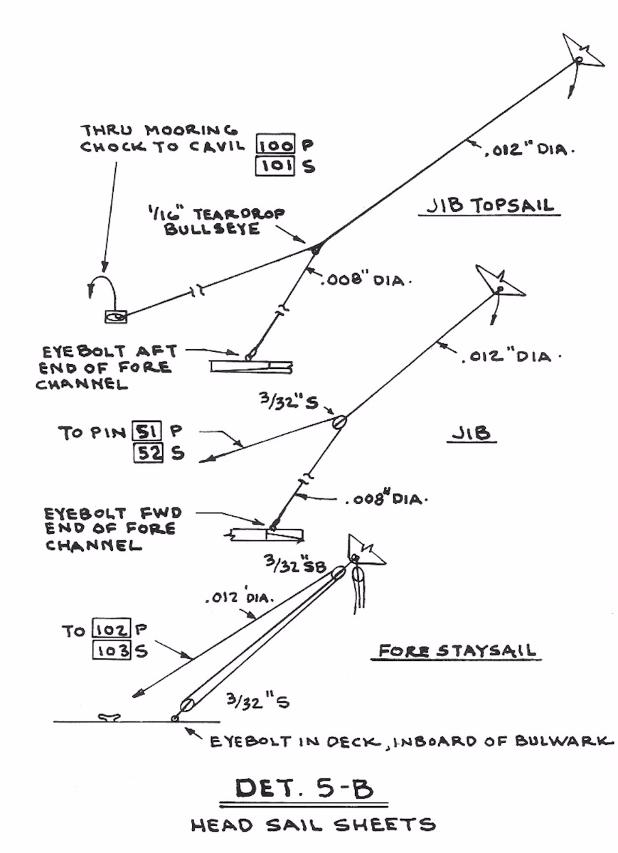
The sheets of the fore sails have different formations as seen in the photo below.
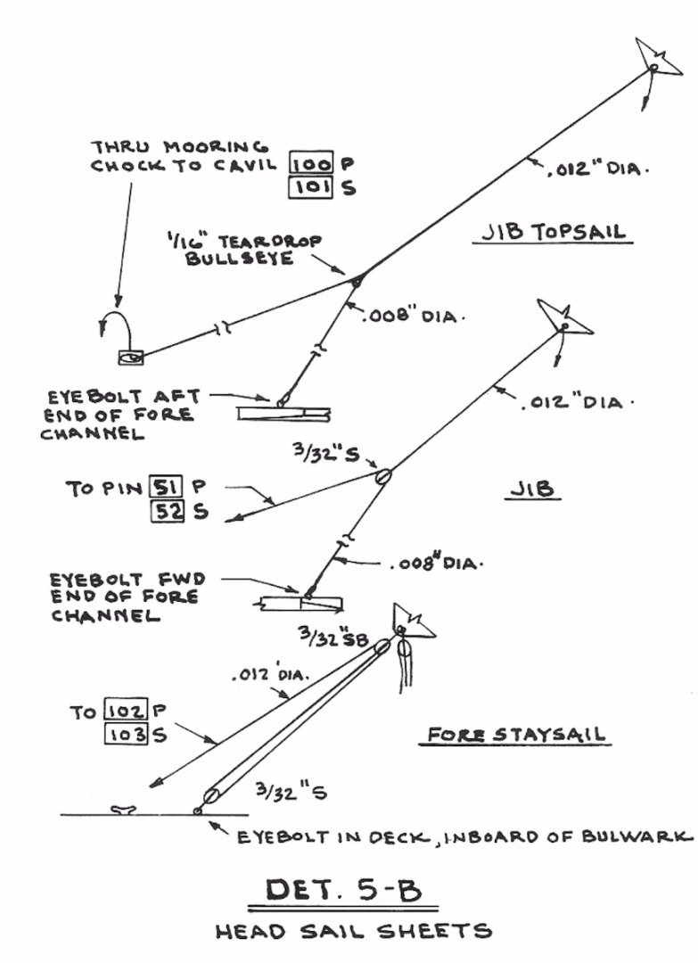
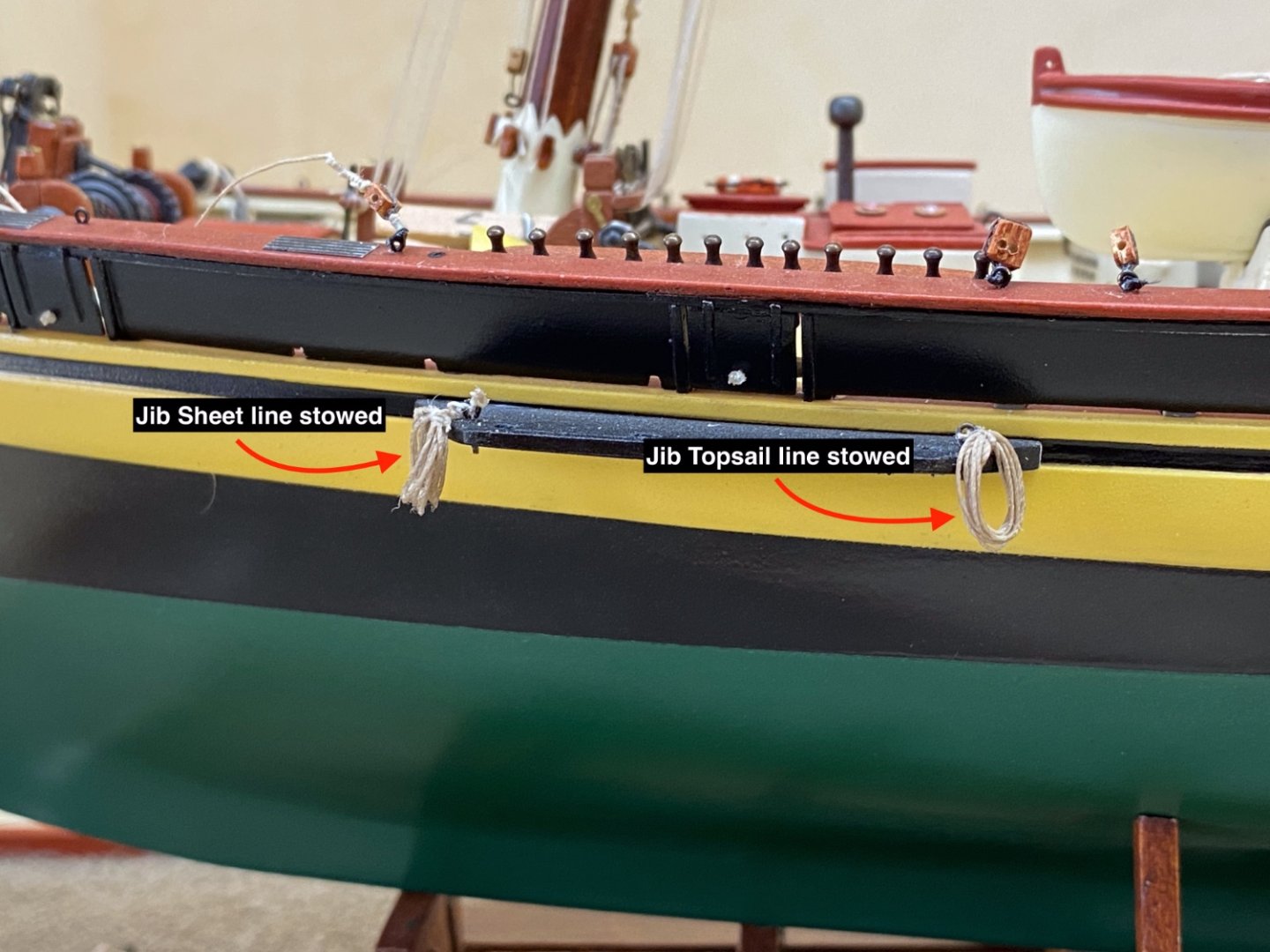
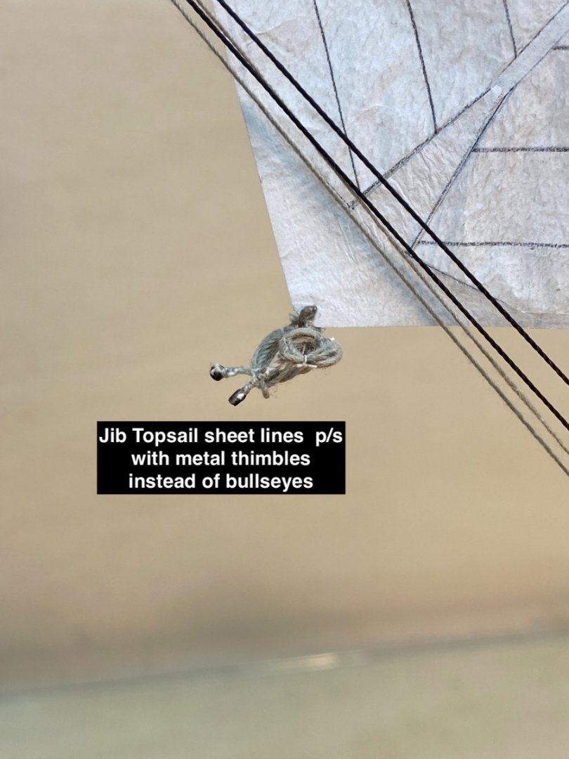
The lines for Jib and Jib Topsail sheet are two independent ones. The lines with blocks or thimbles were seized to sail and stowed. Their counterpart lines seized to the eyebolts at the fore and aft of the chain plate platforms were coiled and stowed in place.
Port side
Starboard side
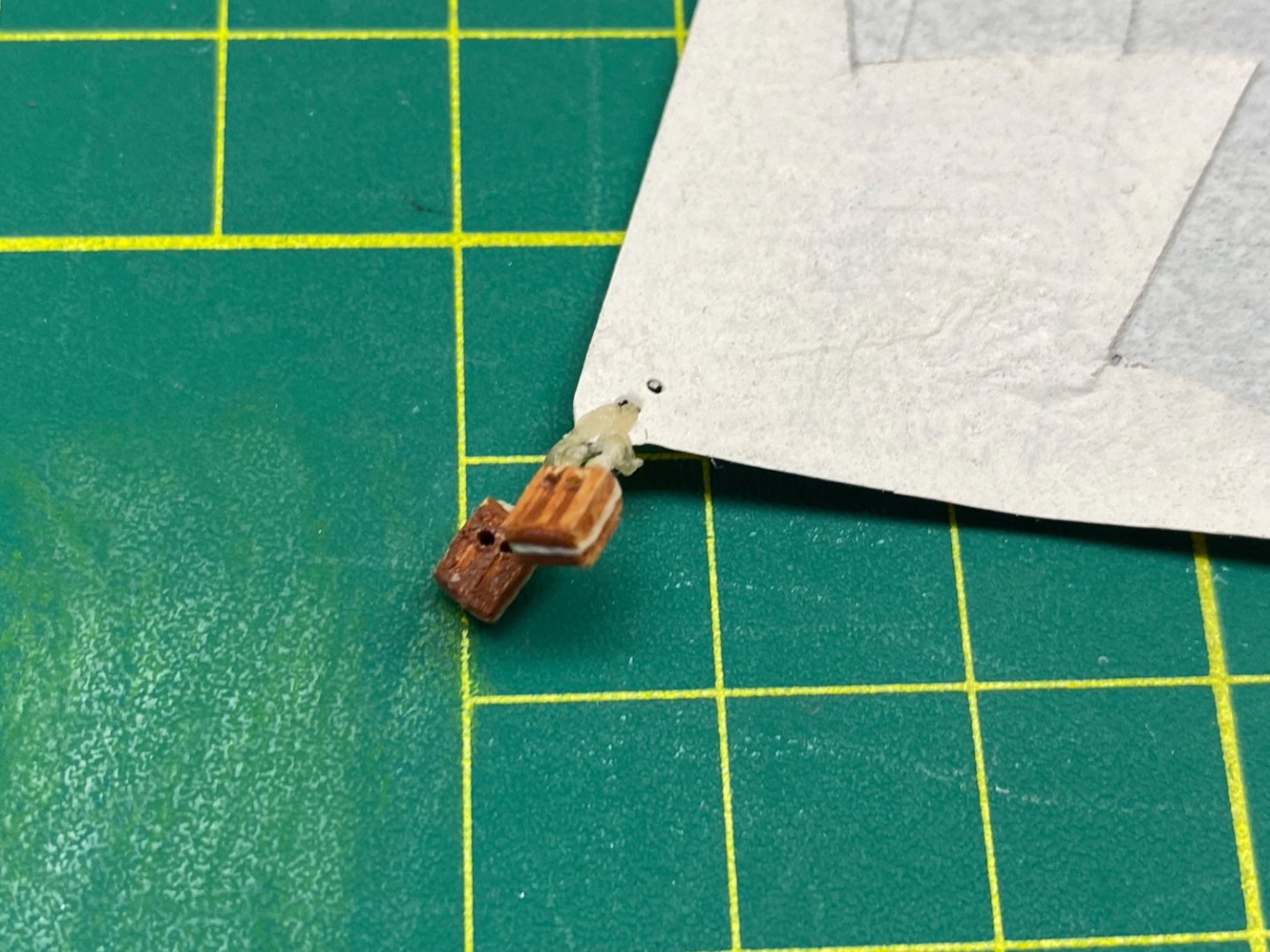
Blocks for Forestay Sail sheet lines were seized to their eyebolts. The blocks with pendant lines were coiled and stowed at the sail.
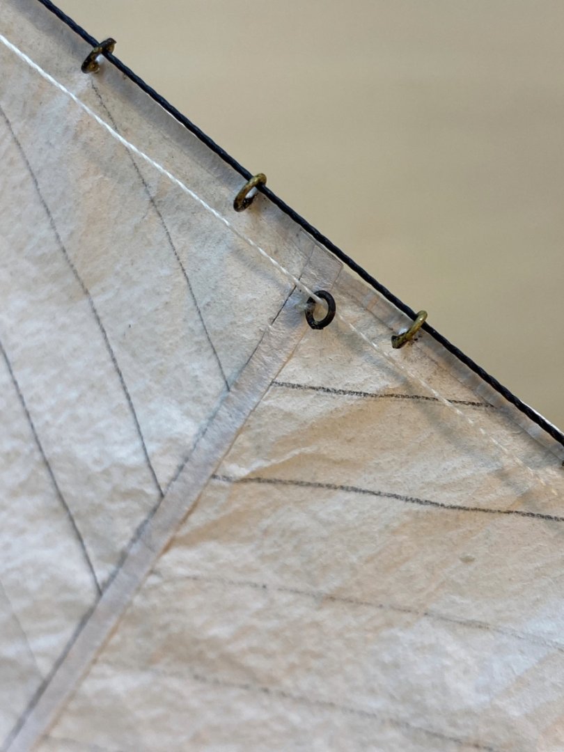
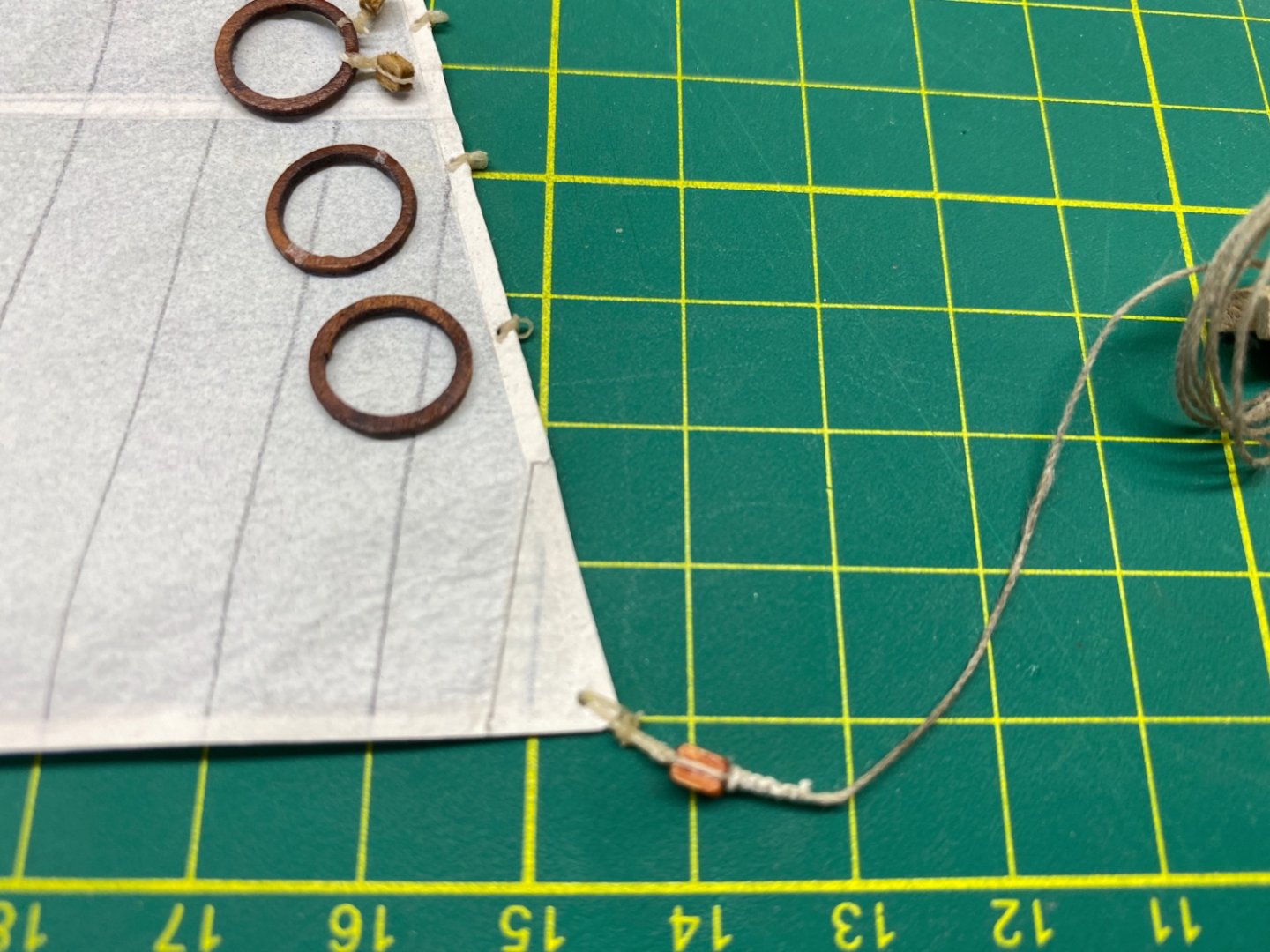
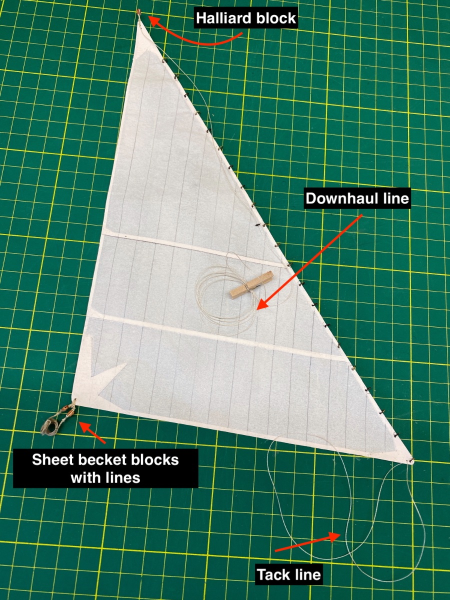
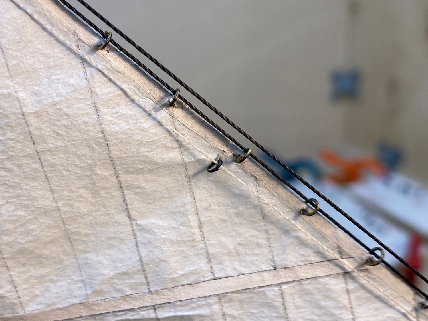
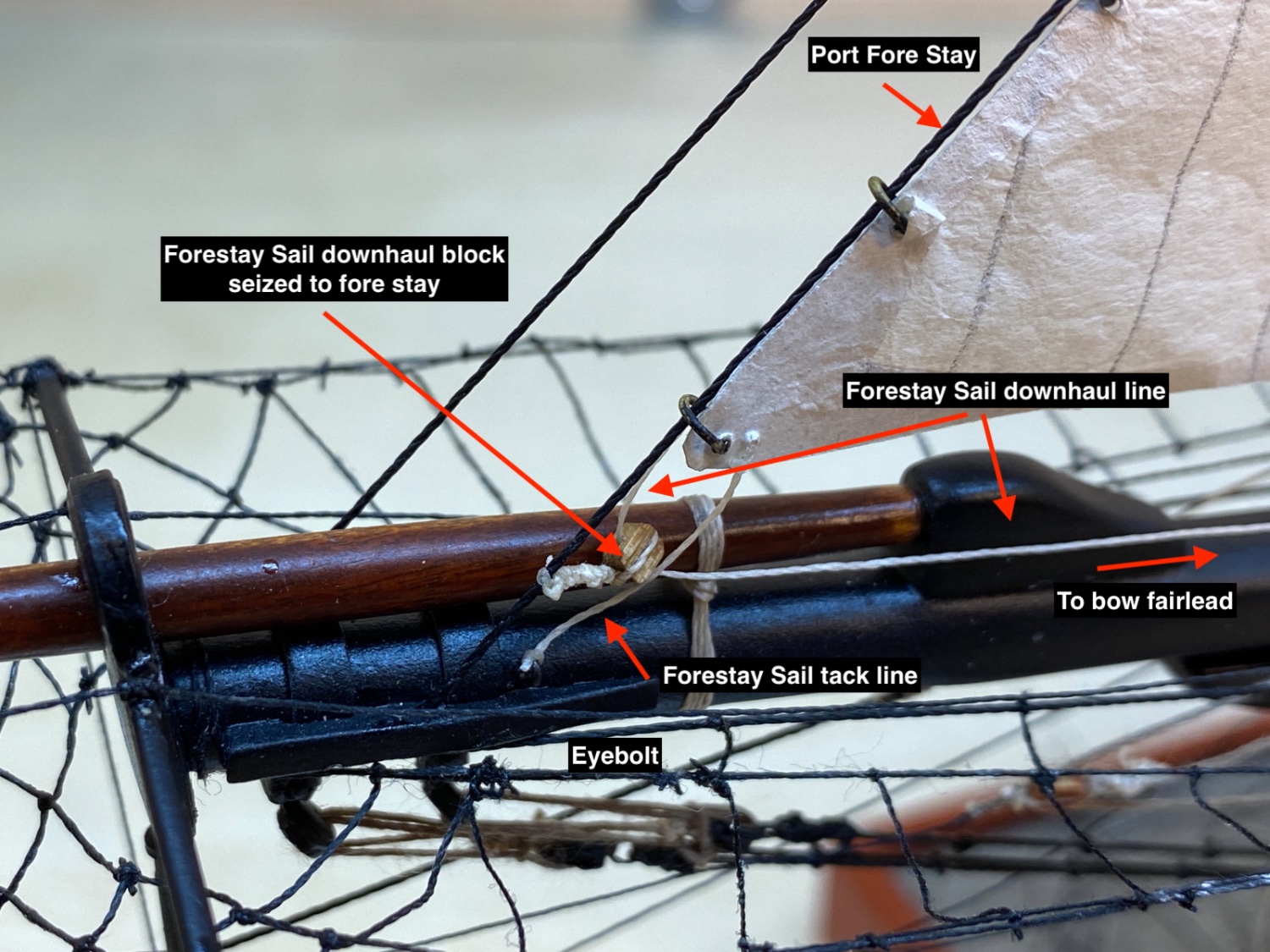
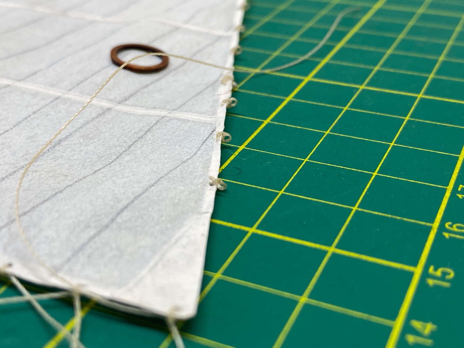
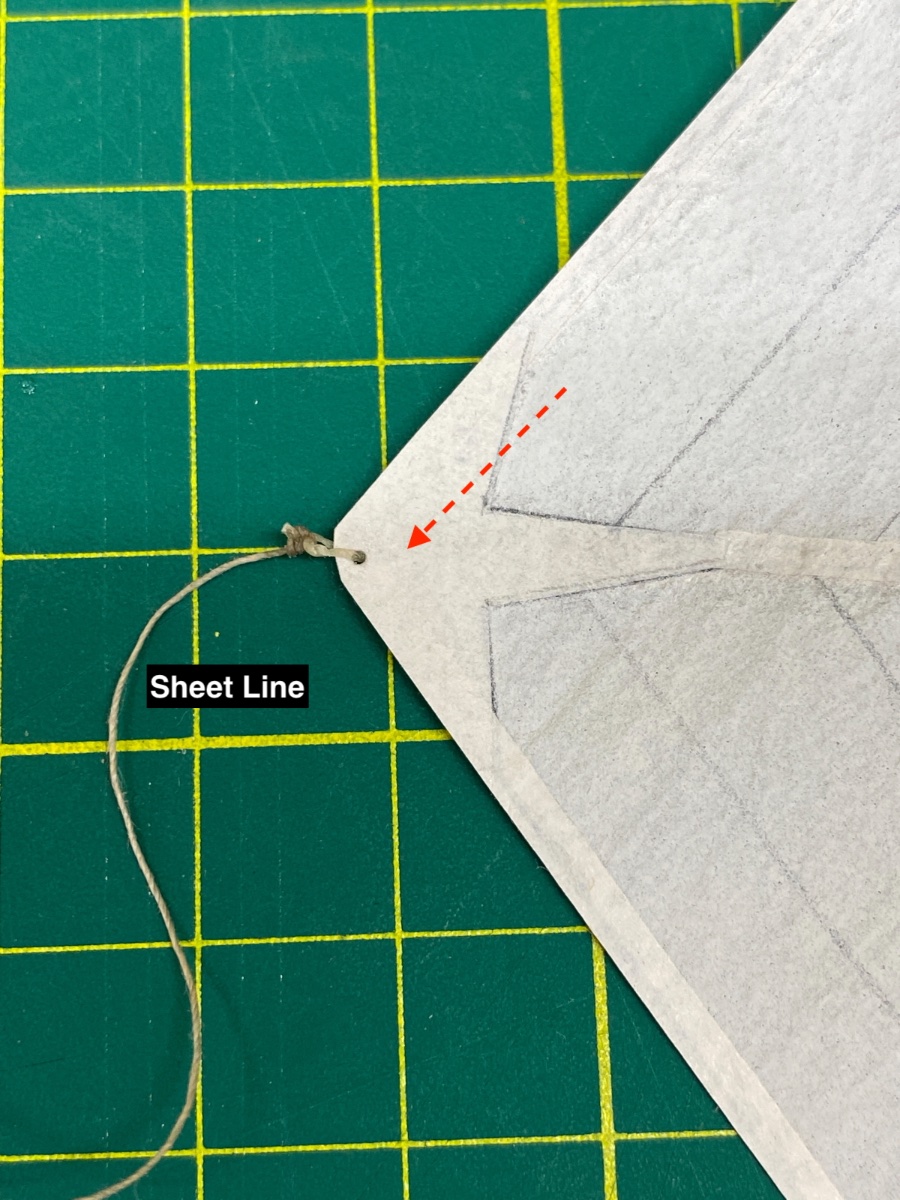
In all three sails metal rings were placed through which stay lines will pass. Halliard blocks, downhaul lines, tack lines were seized as well as the coiled sheet lines with blocks or thimbles.
Here is a photo of Forestay Sail with legends.

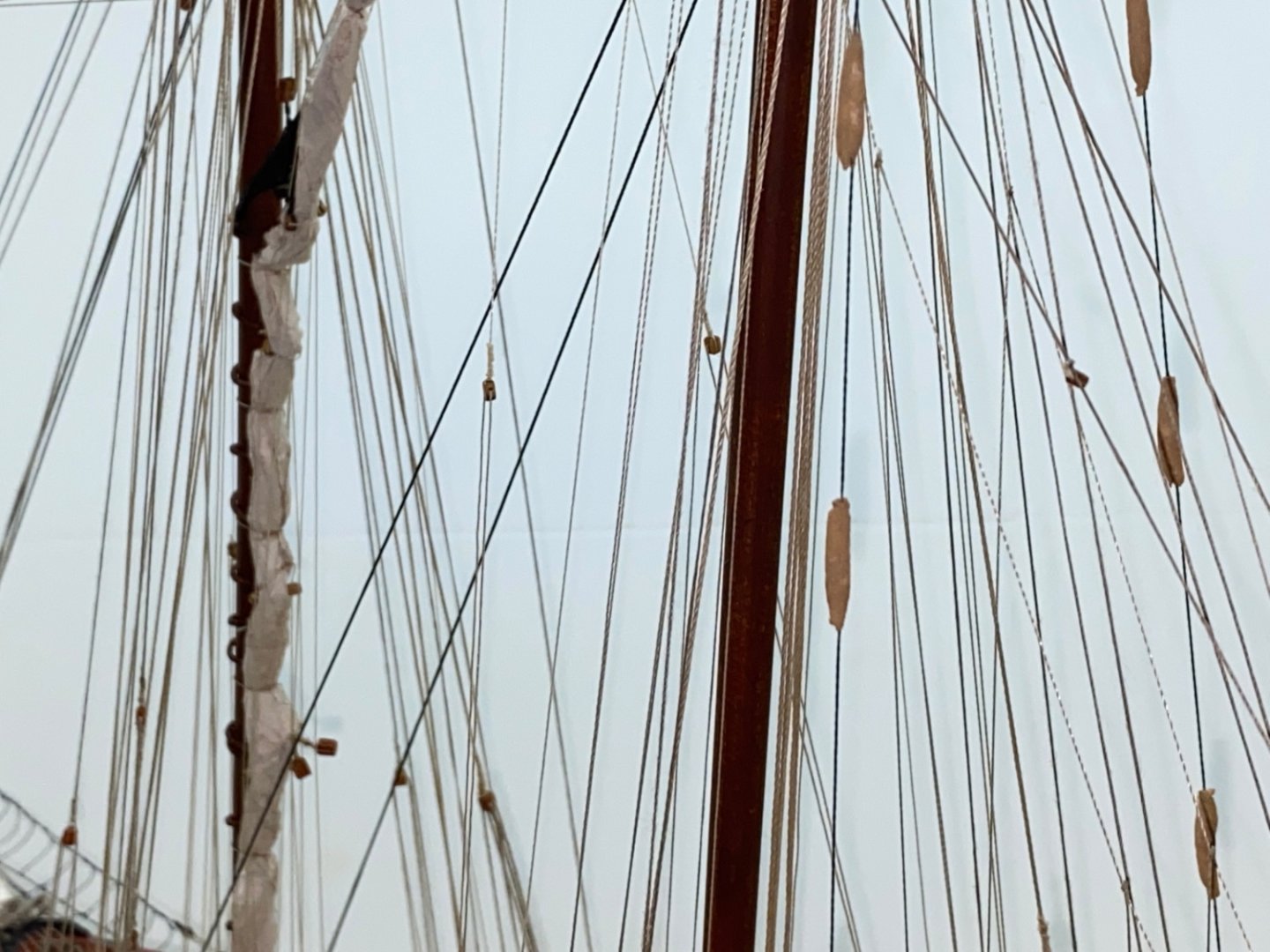
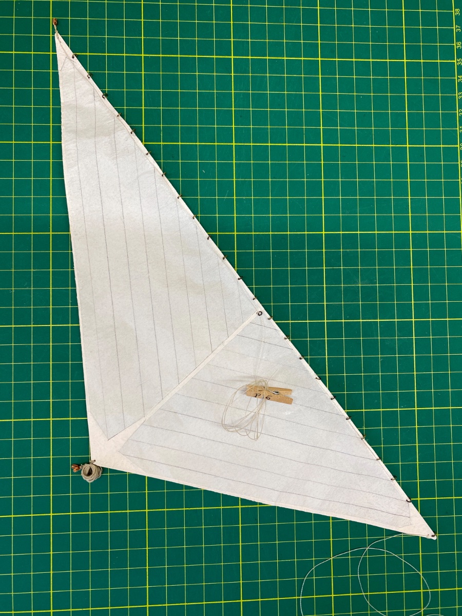
Here is Jib and Jib Topsail photos.

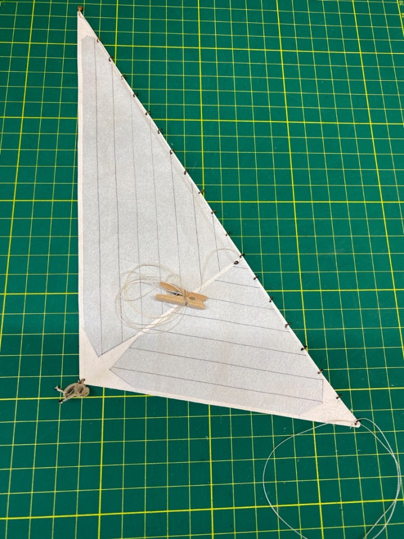
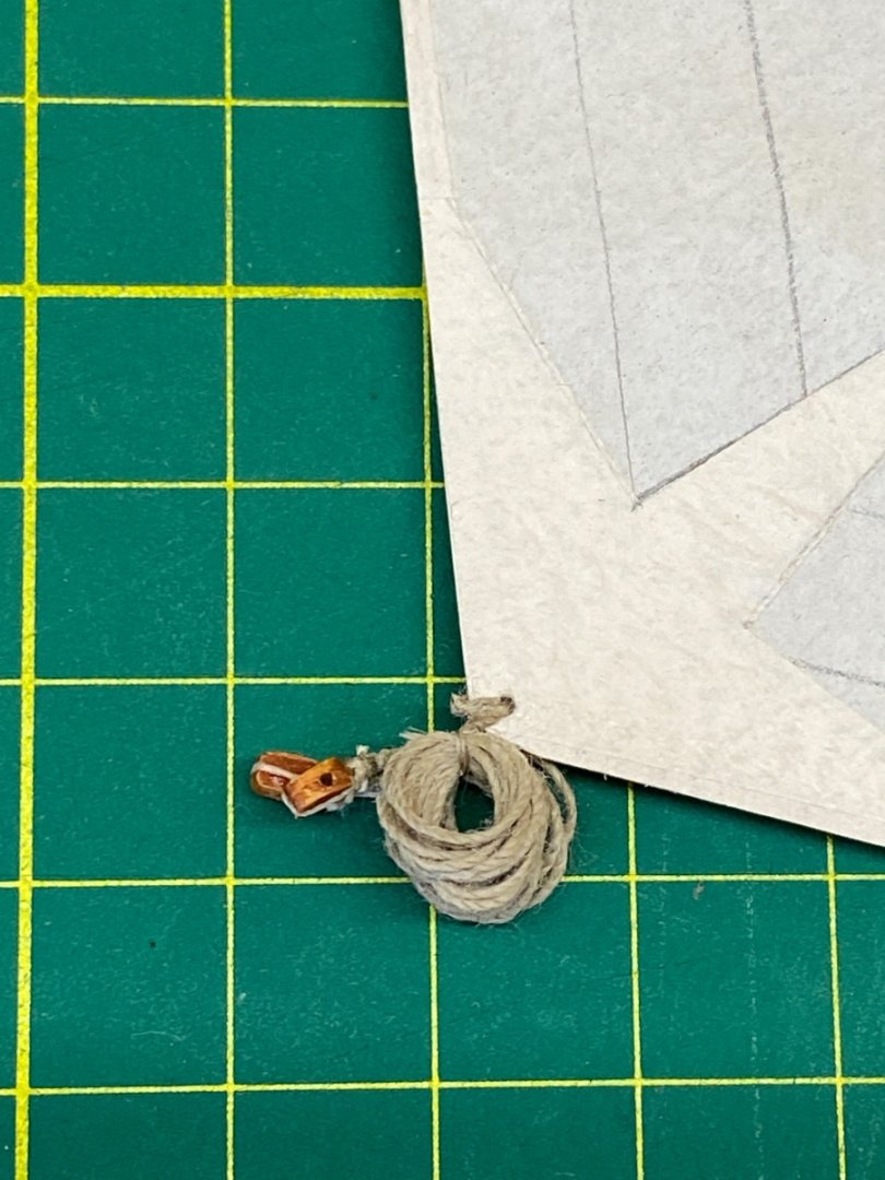
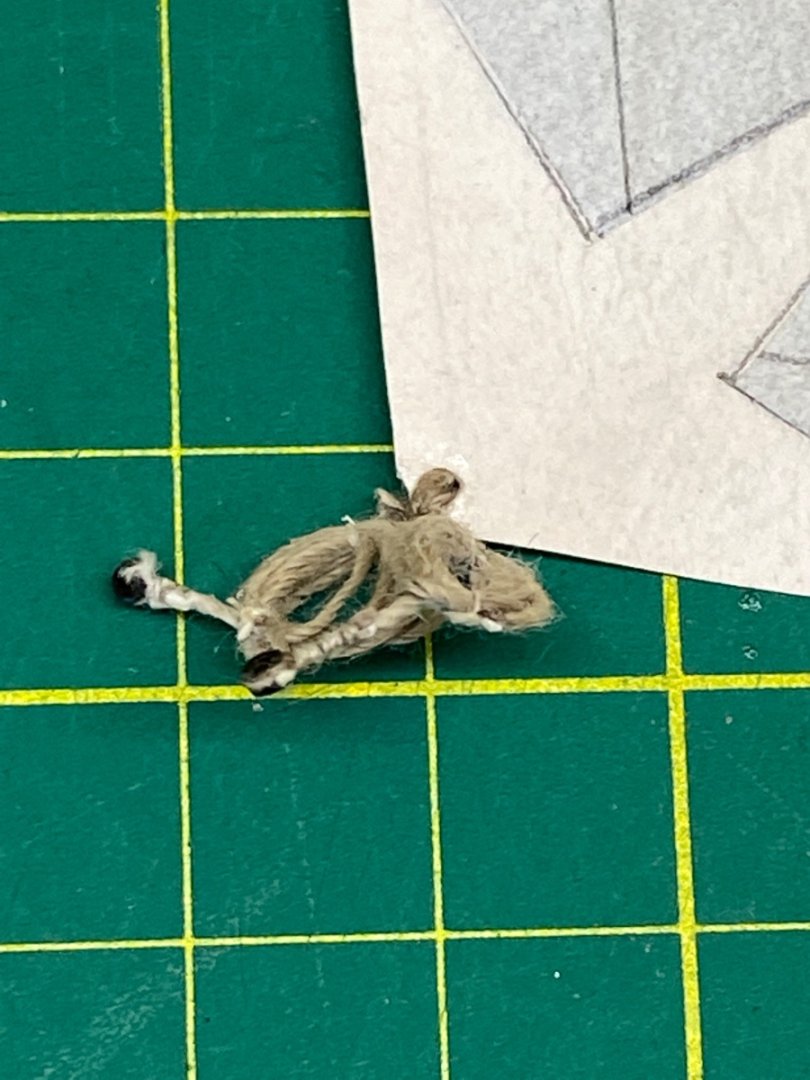
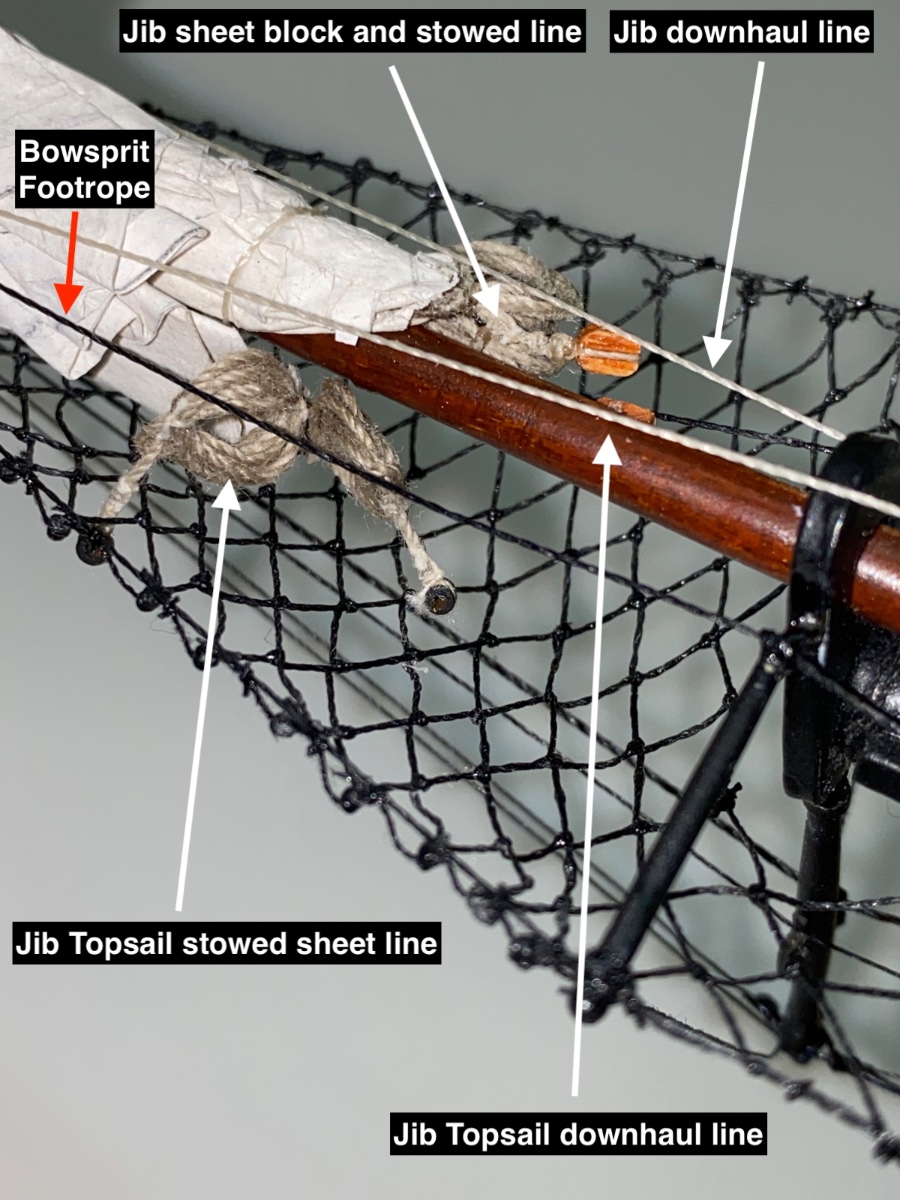
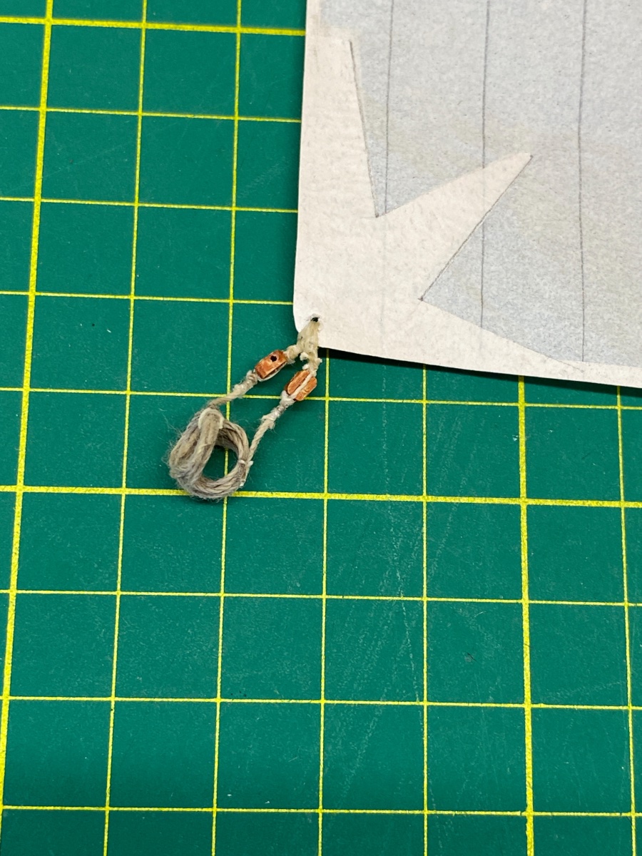
Here are the closeup photos of the sheet lines and blocks in the order of Forestay Sail, Jib and Jib Topsail.

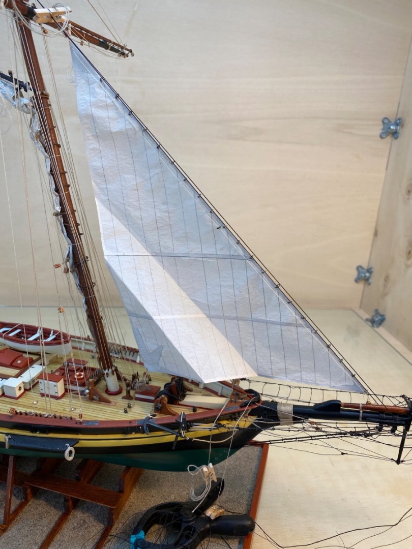
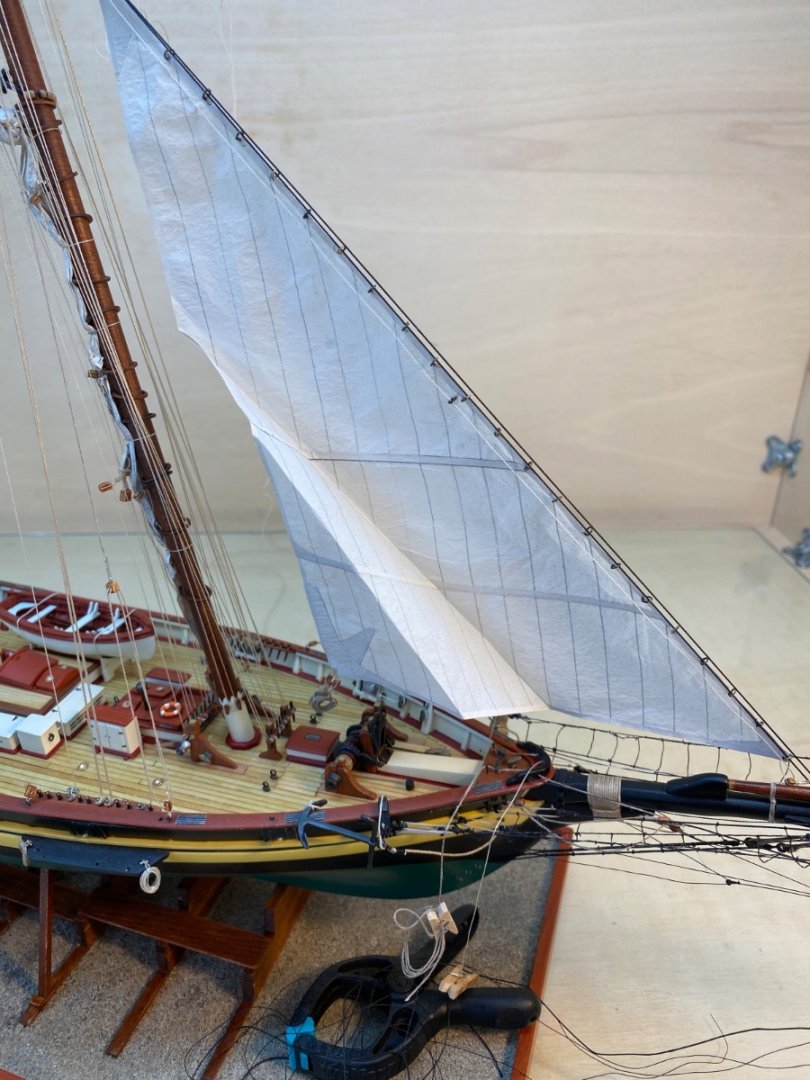
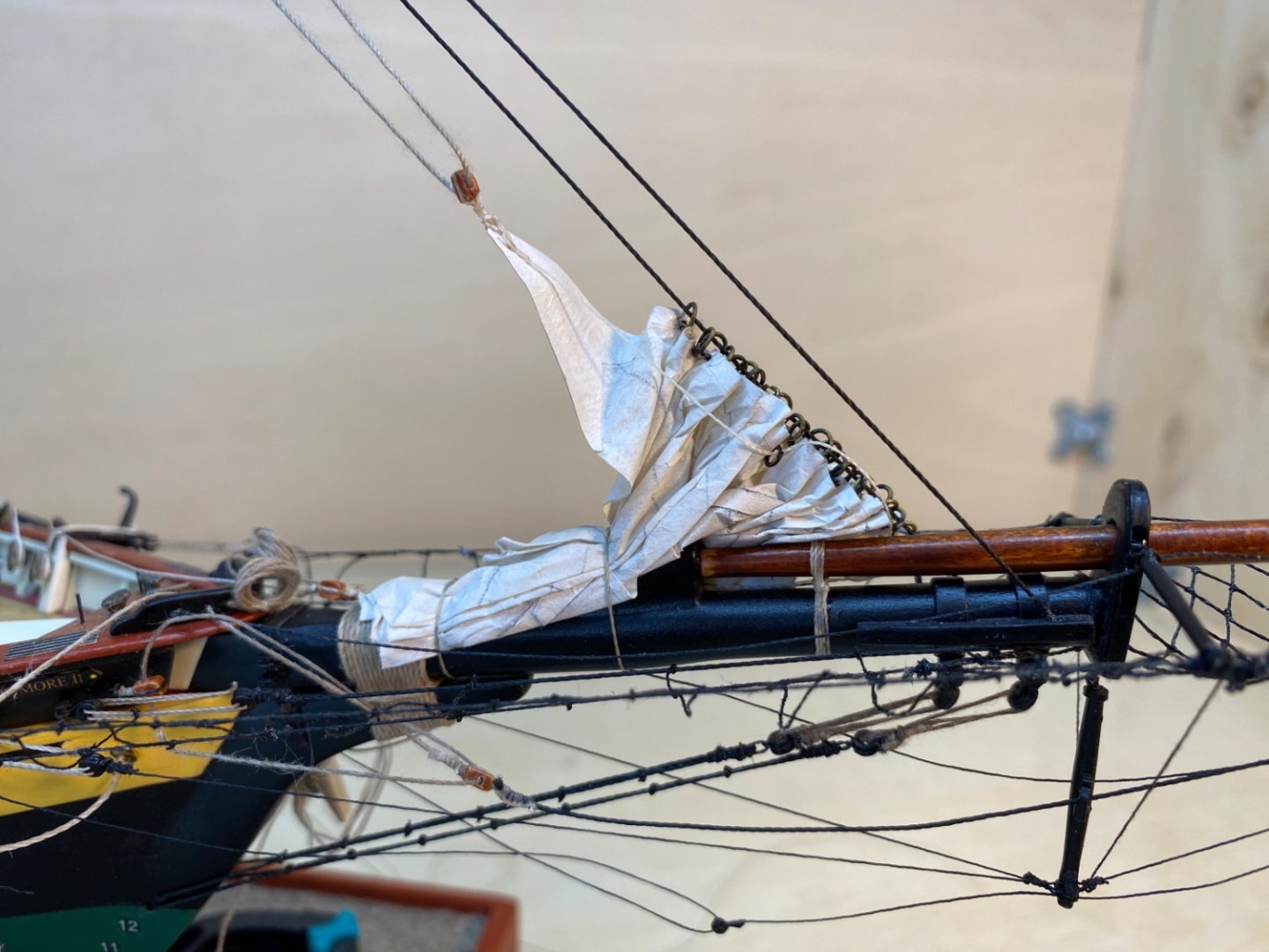
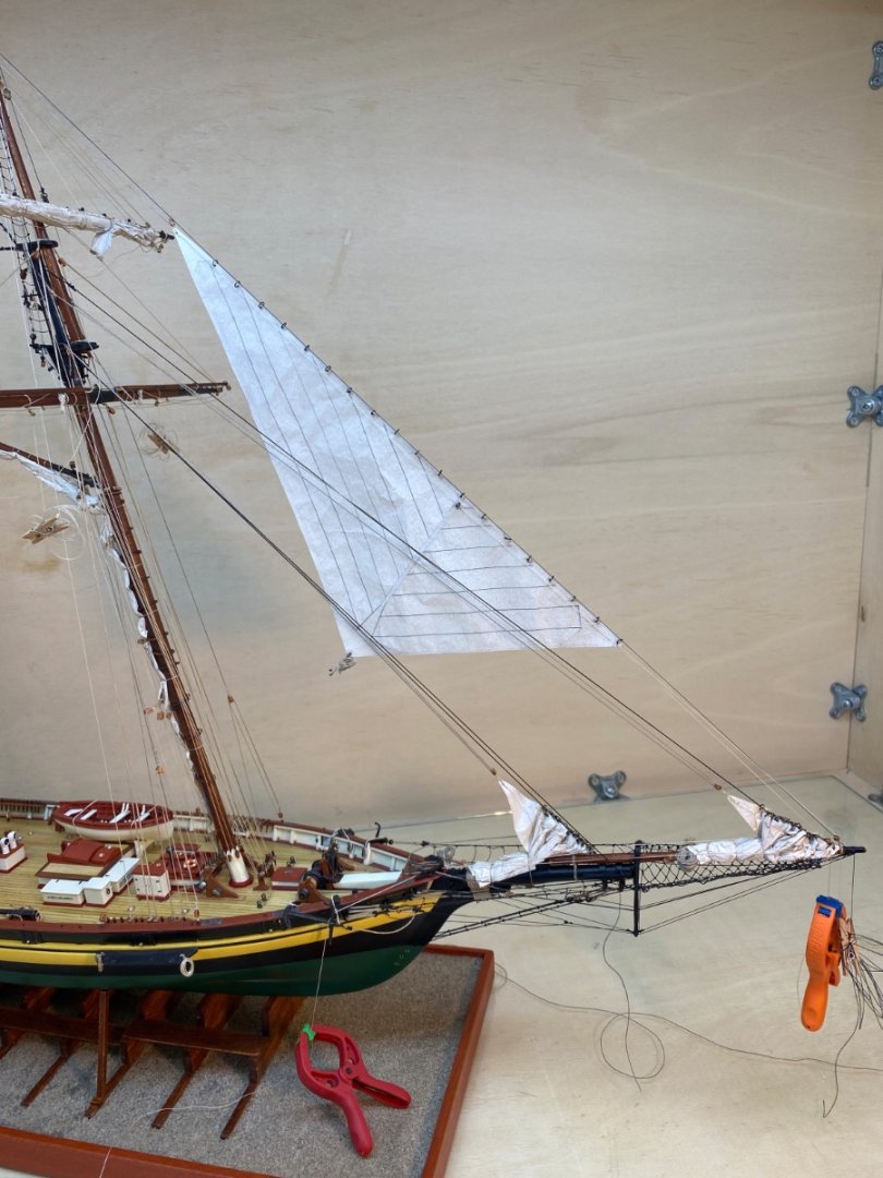
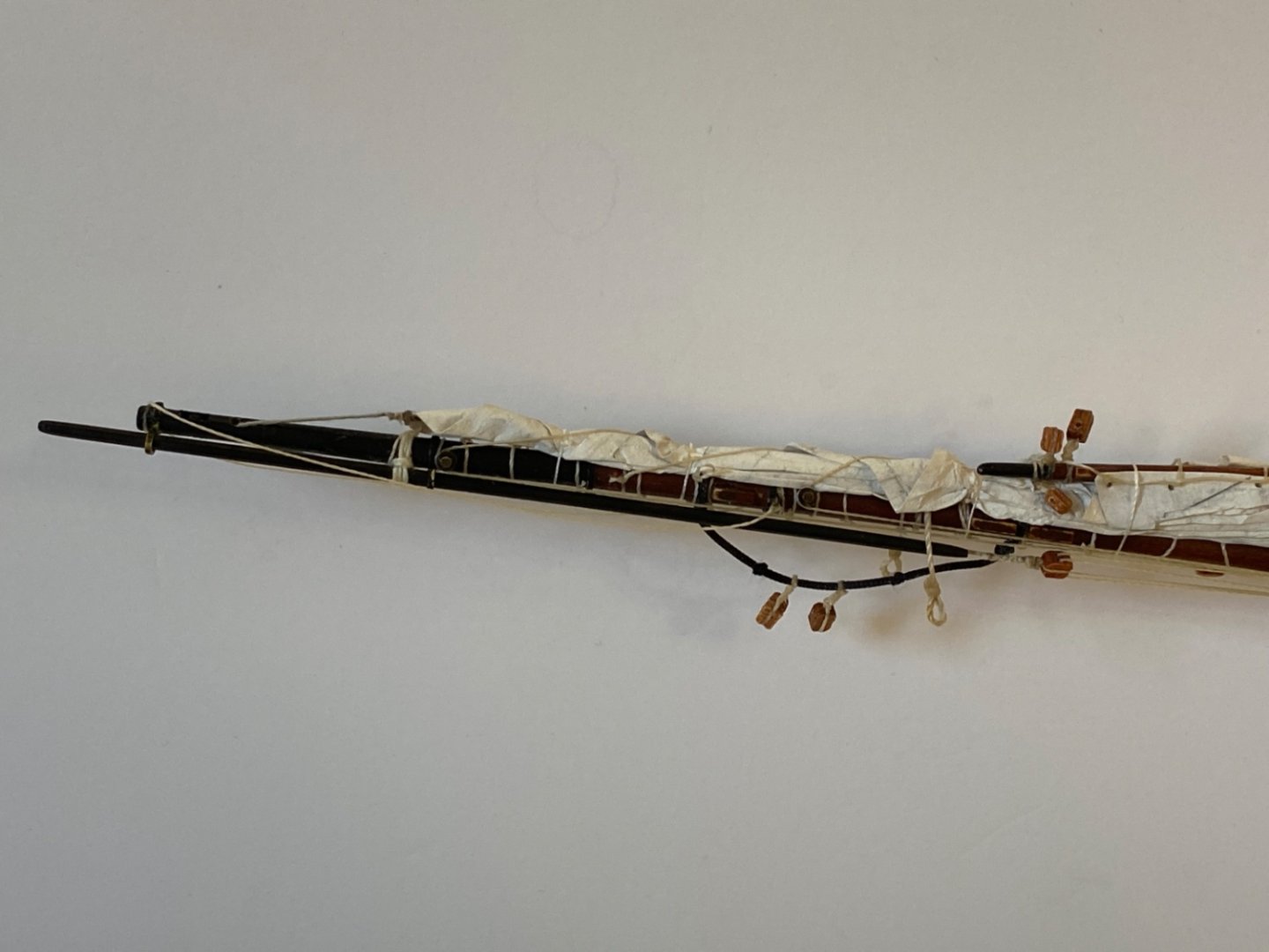
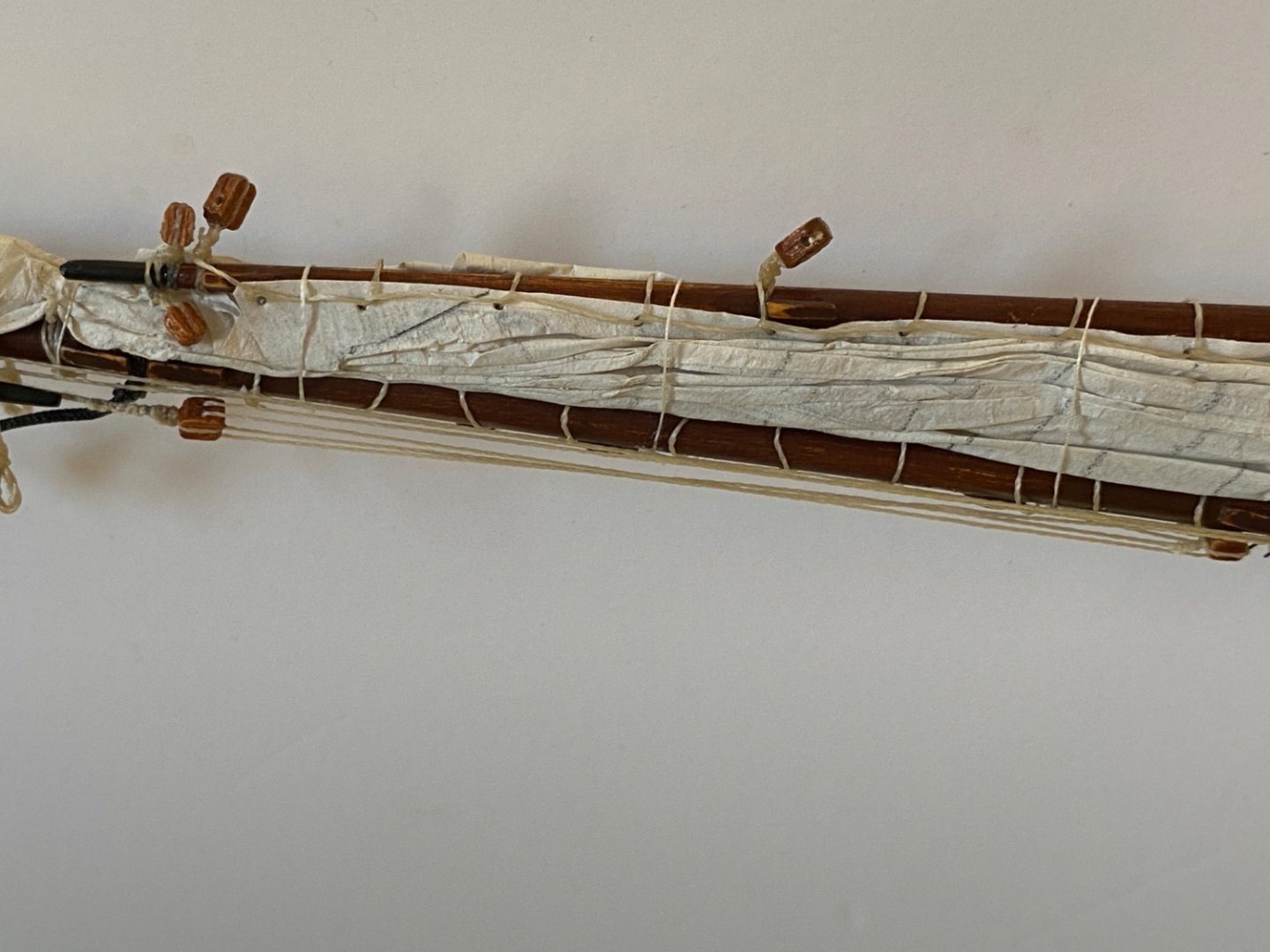
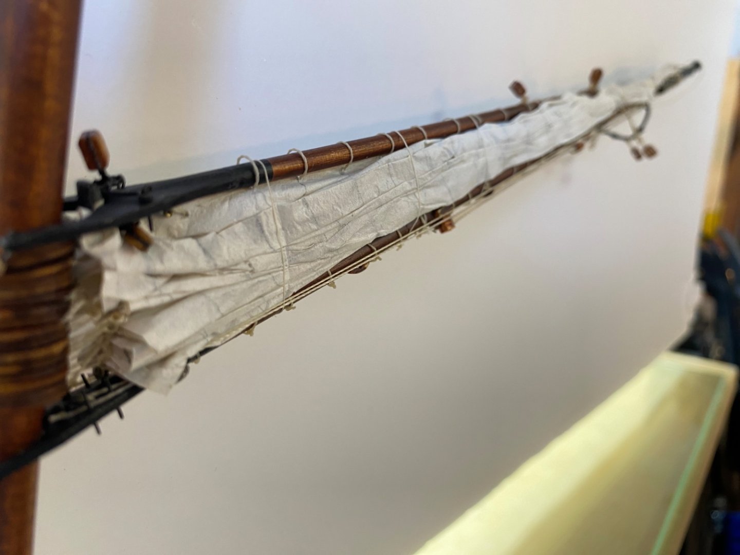
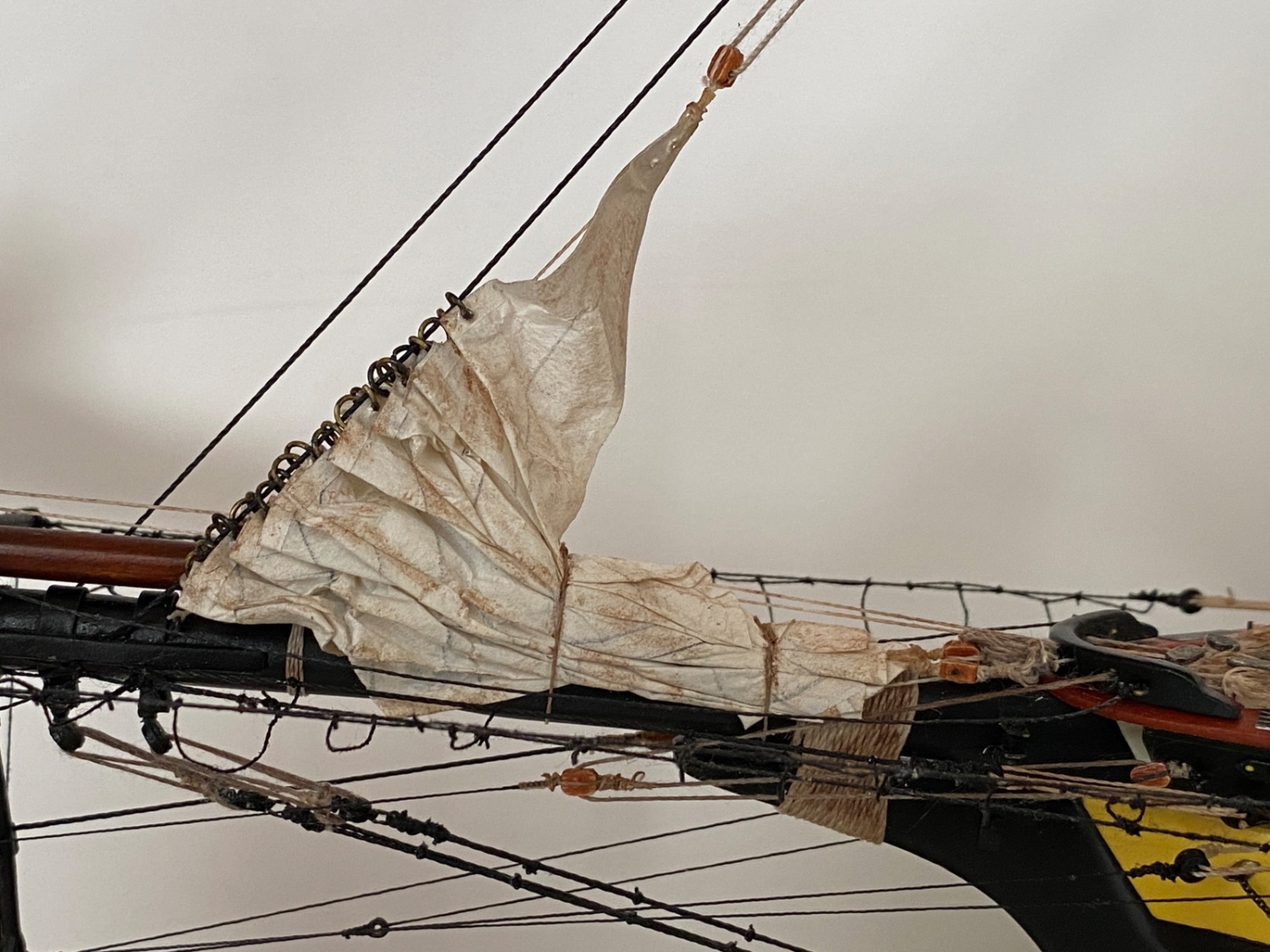
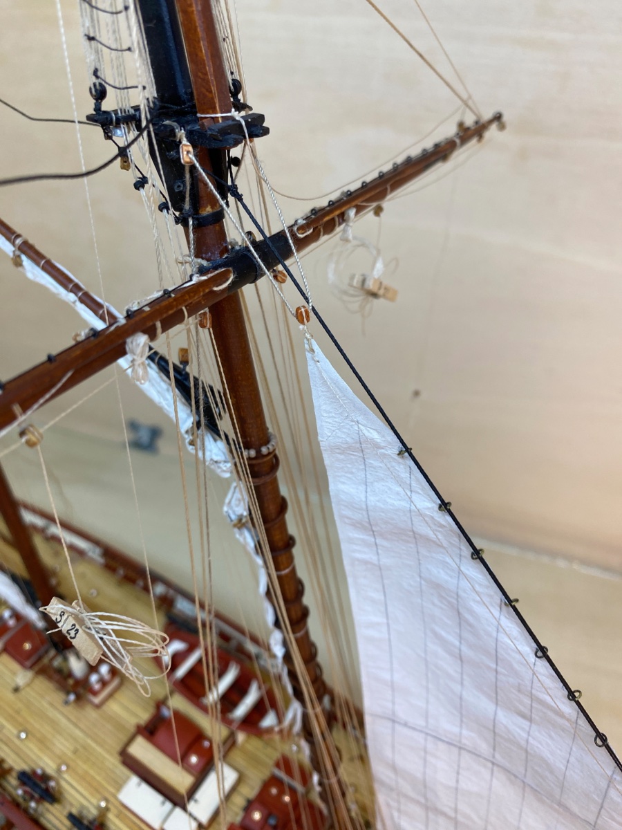
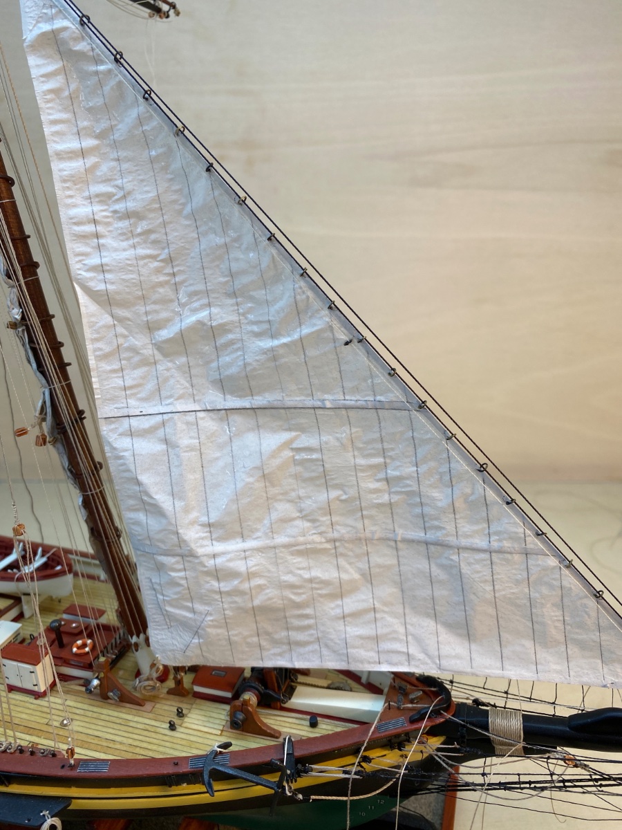
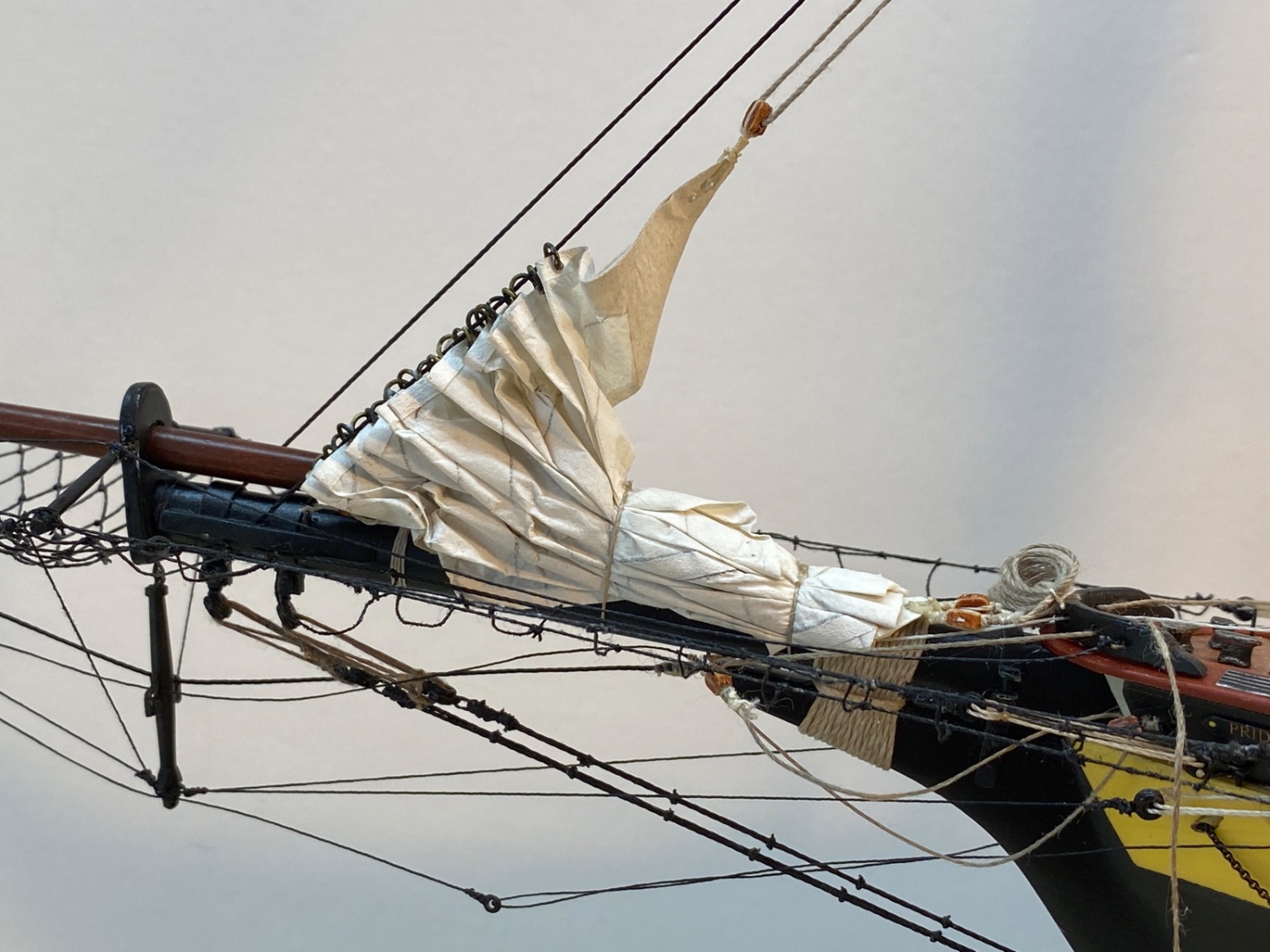
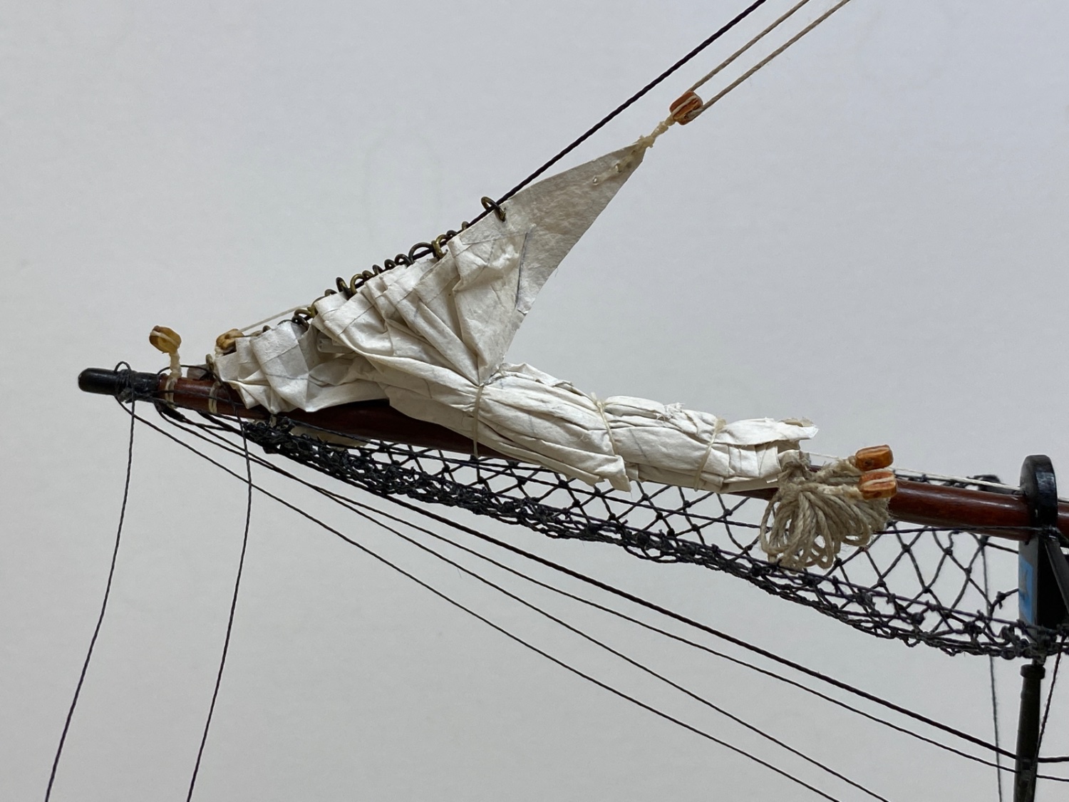
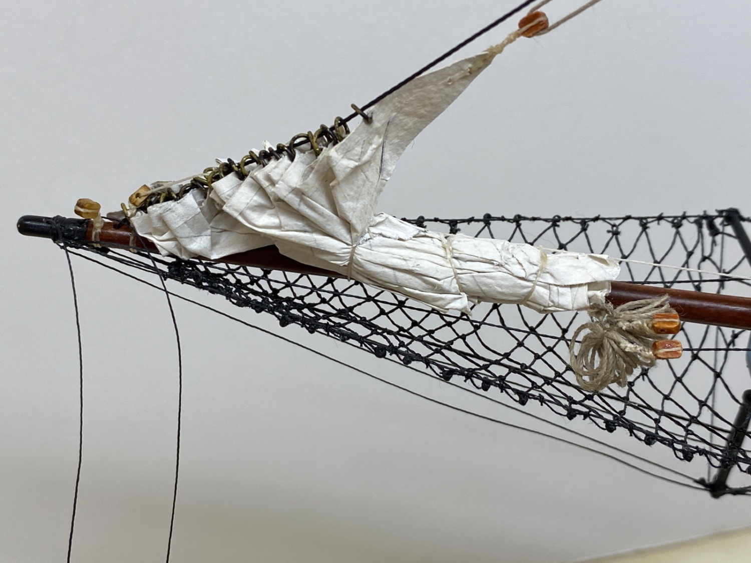
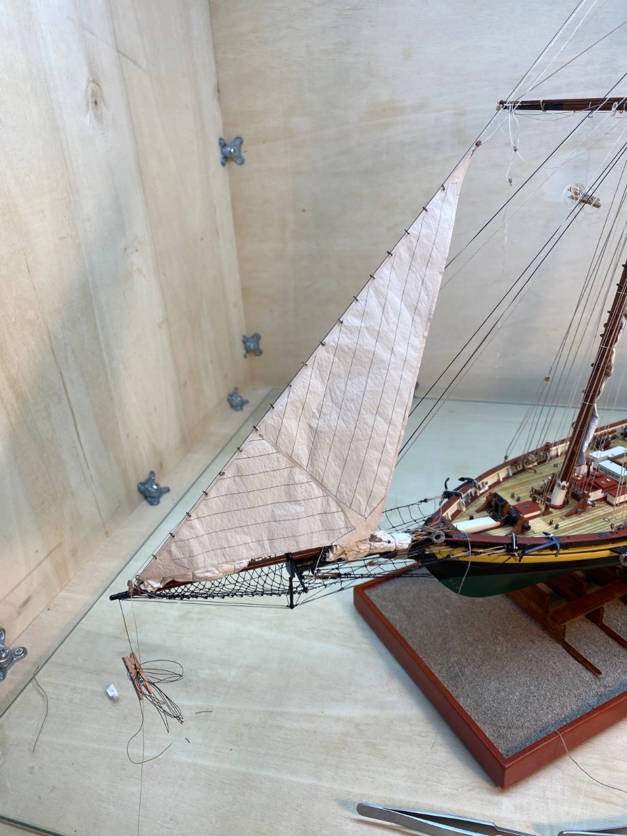
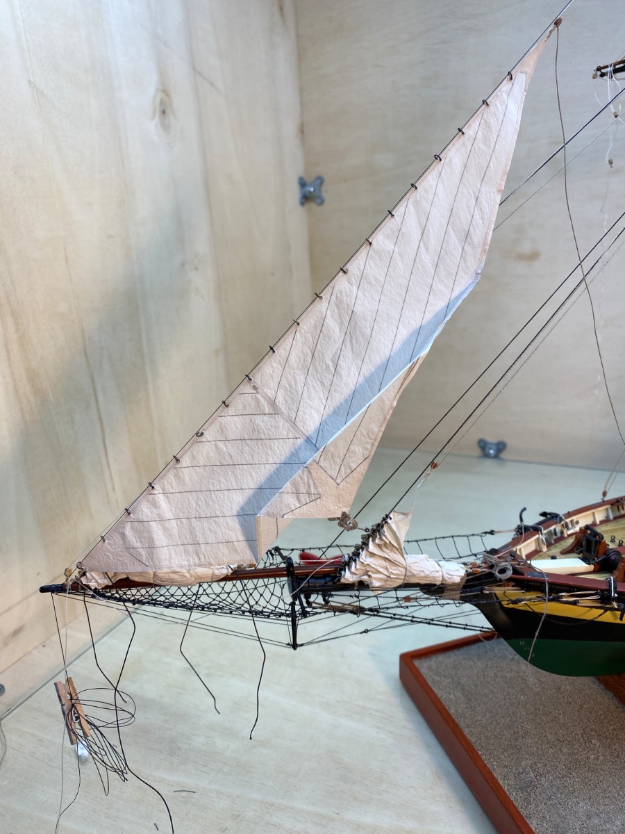
I started with the Forestay Sail. The sail was seized to PORT fore stay. Then both fore stays were seized to fore mast head. The halliard line was reeved through the related blocks and sail was fixed temporarily. Here are some photos of this step, some of which are closeup ones with legends.


Starboard view
Port view

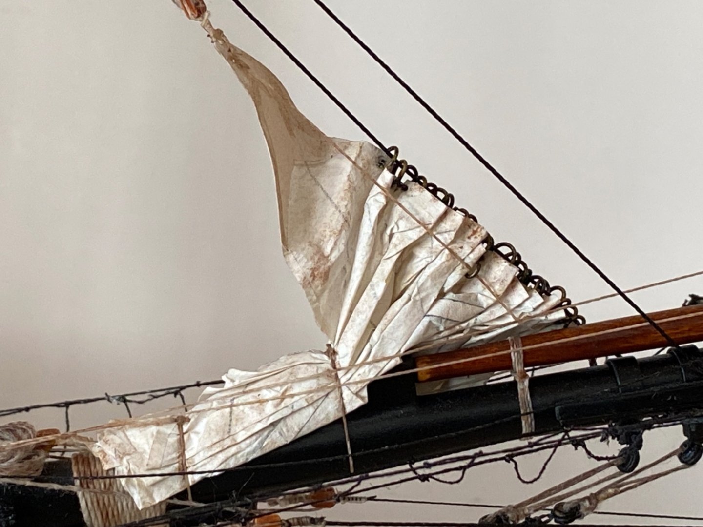
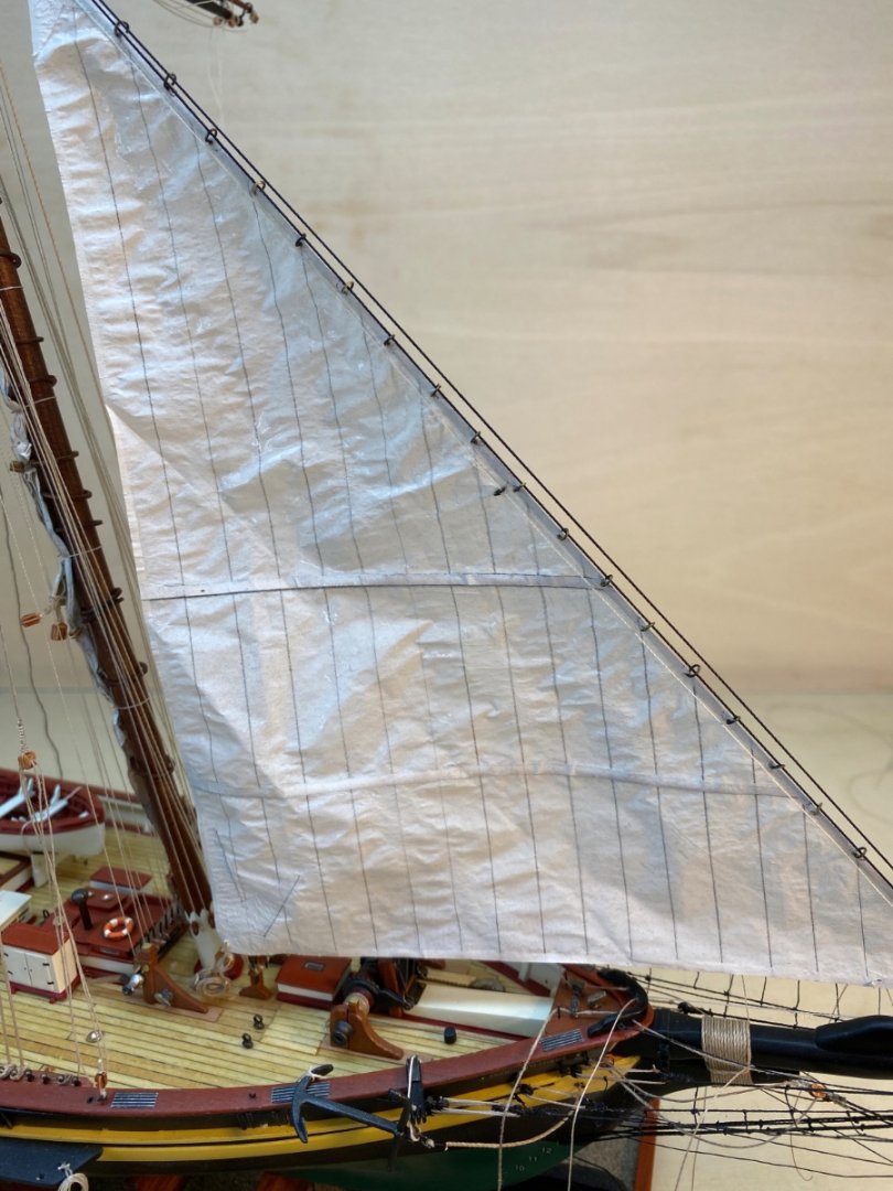
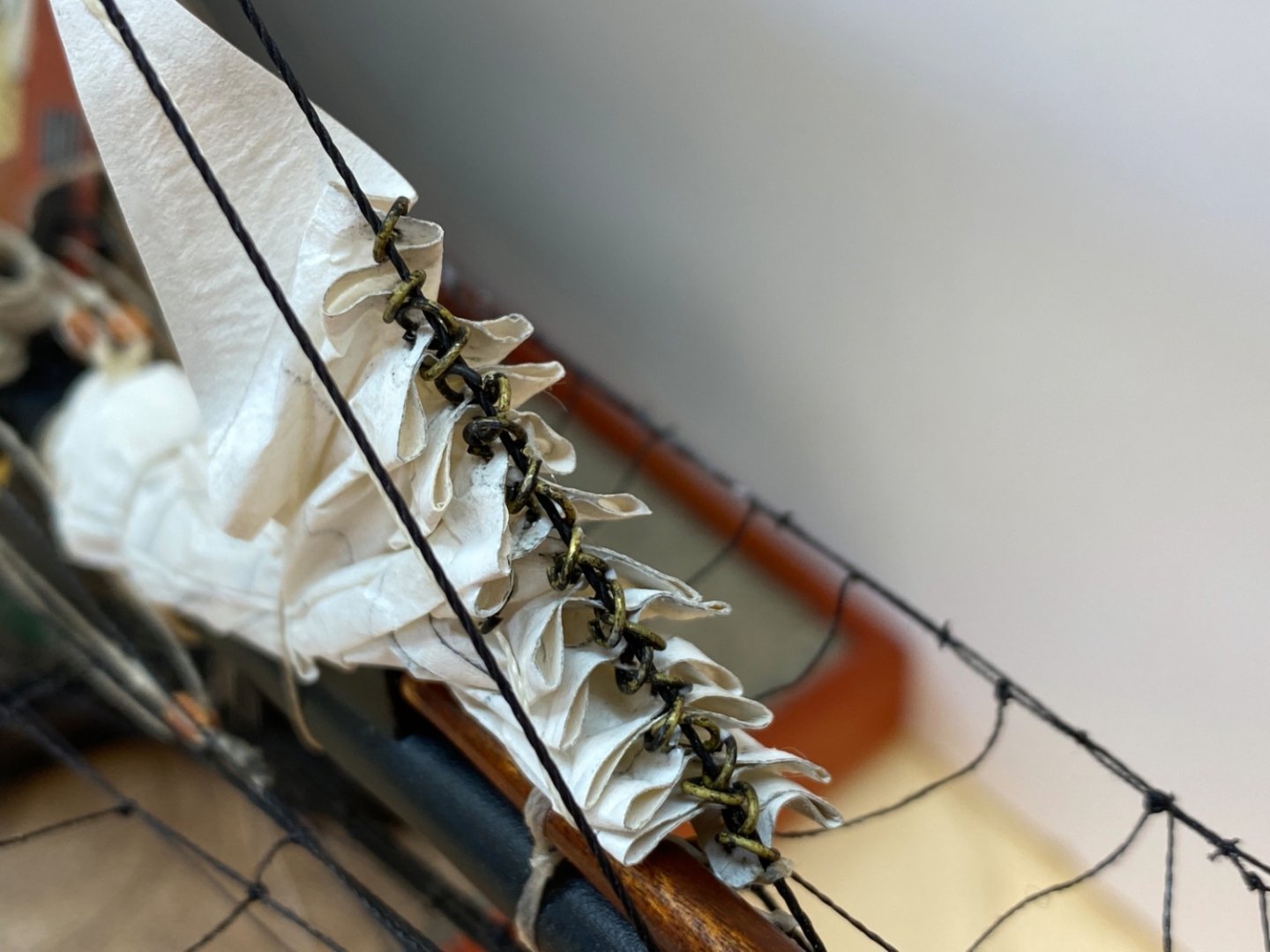
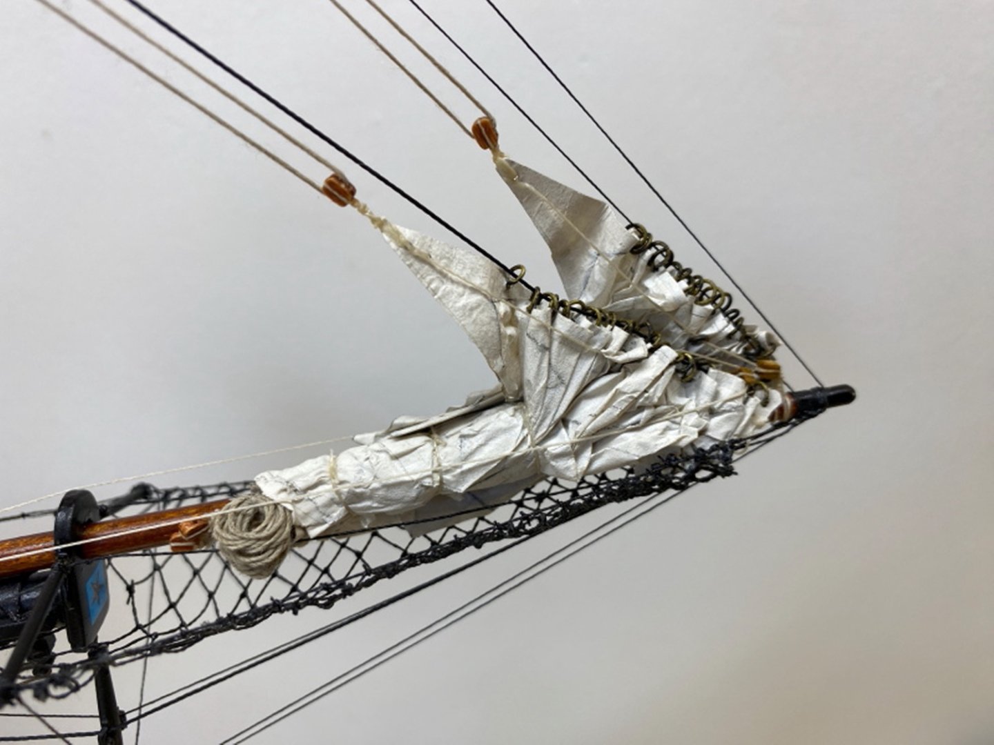
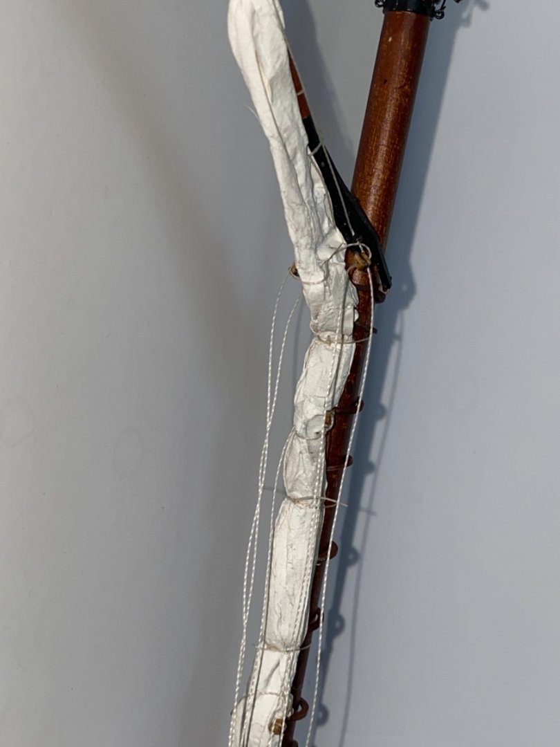
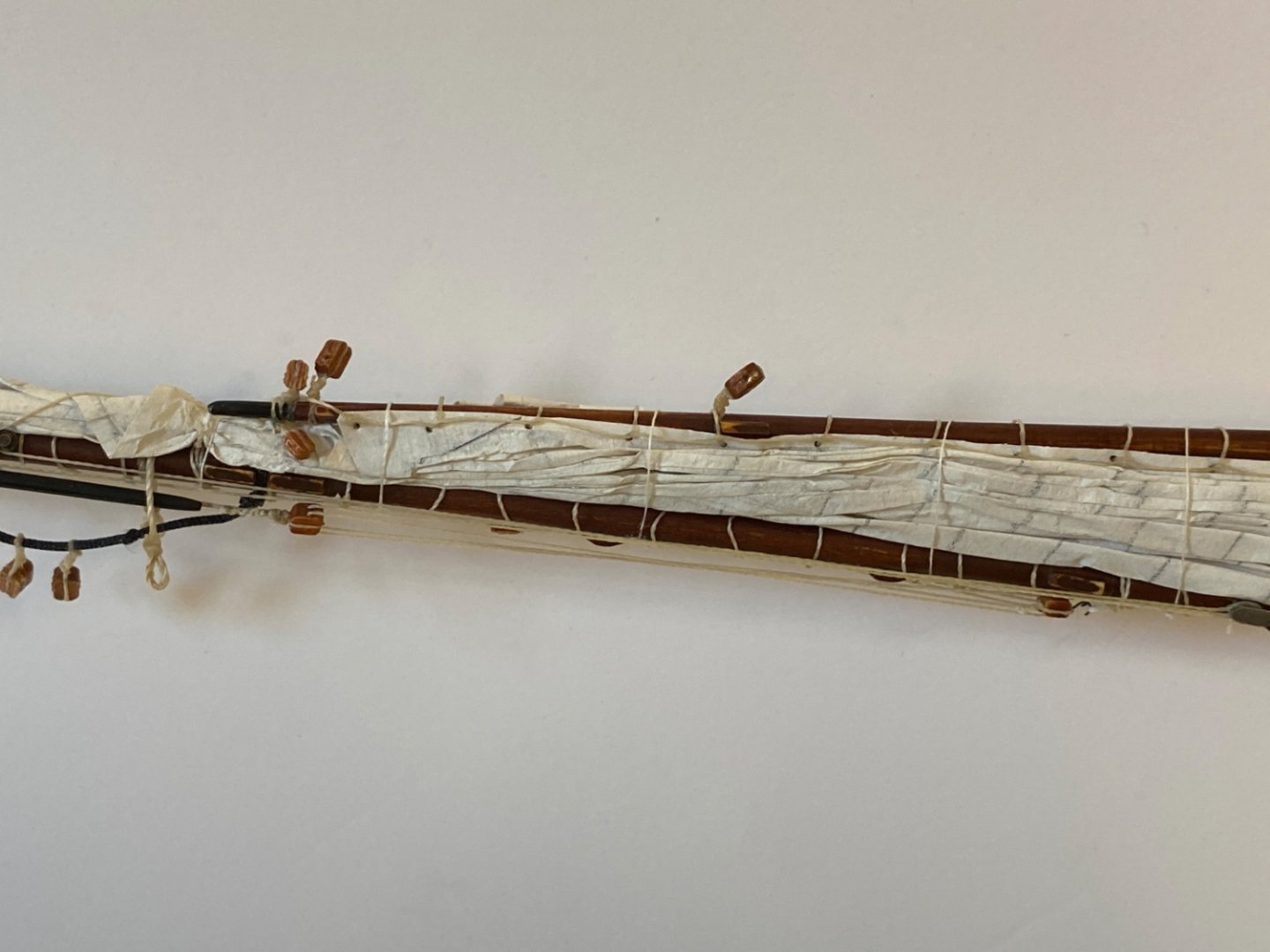
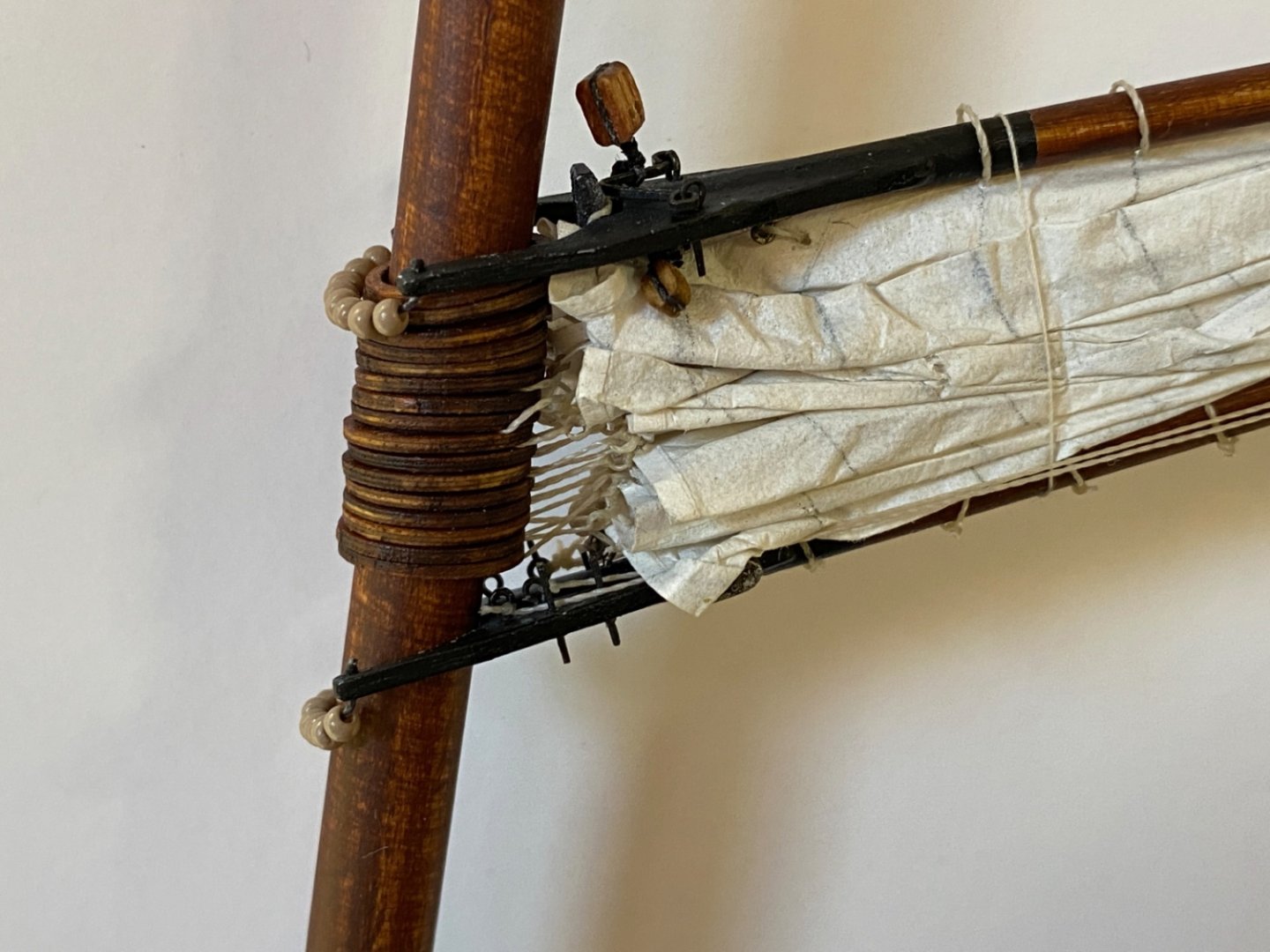
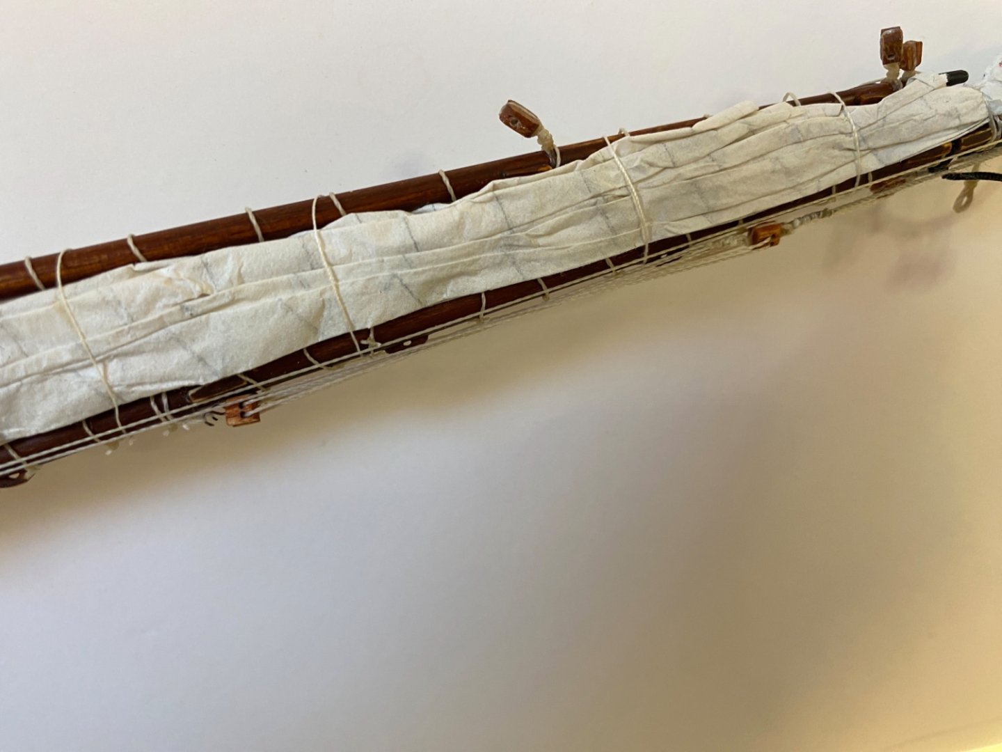
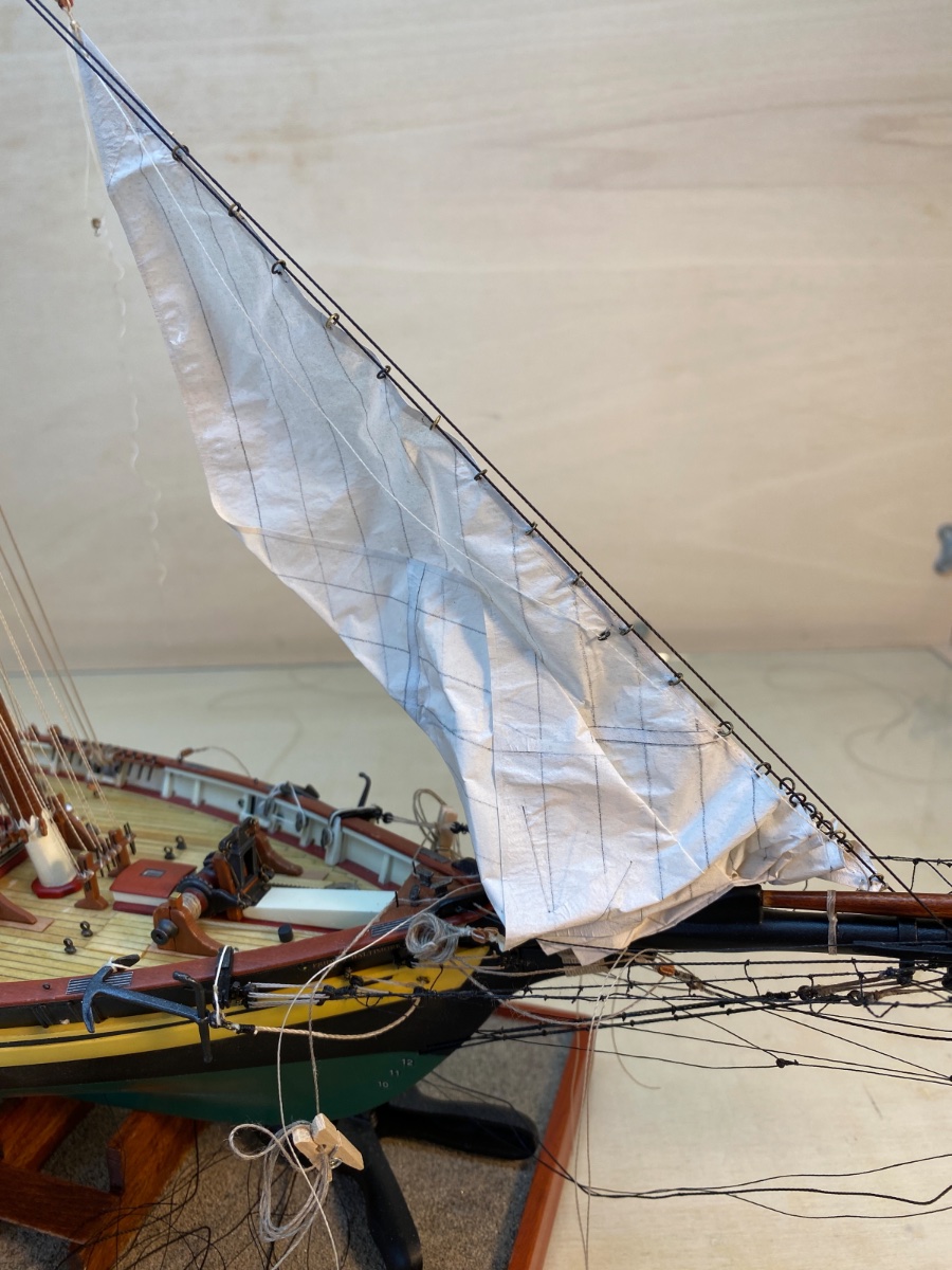
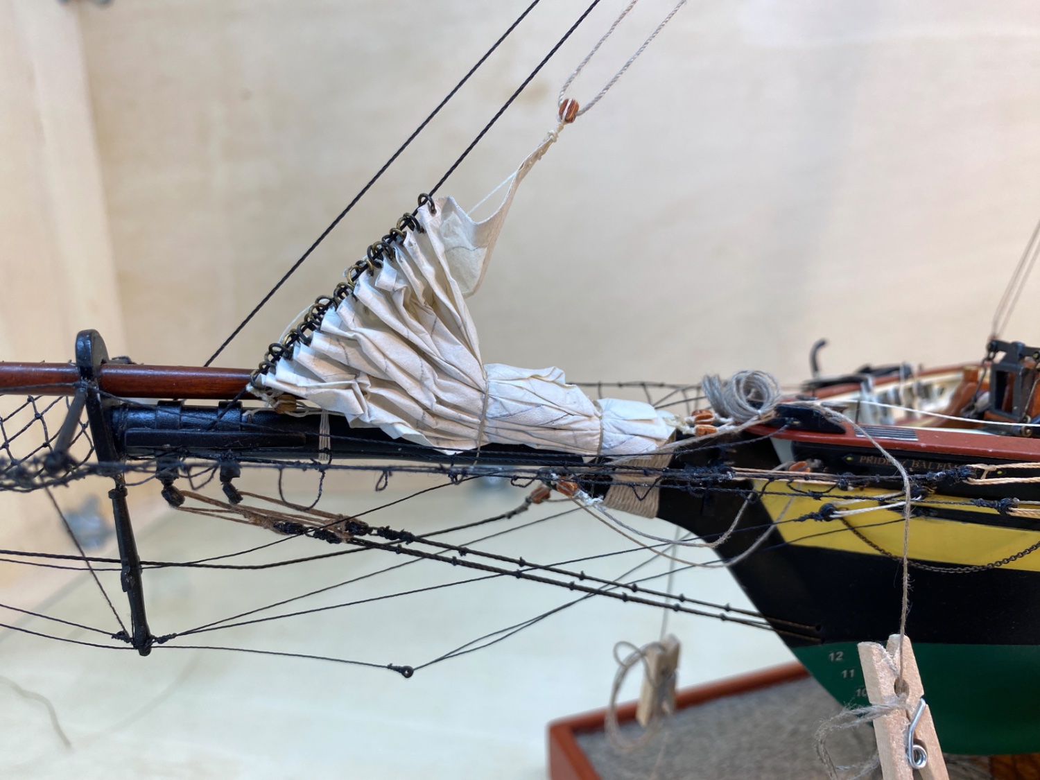
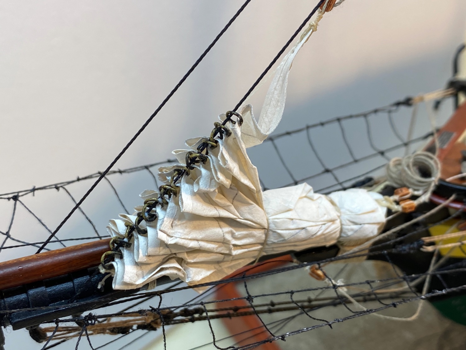
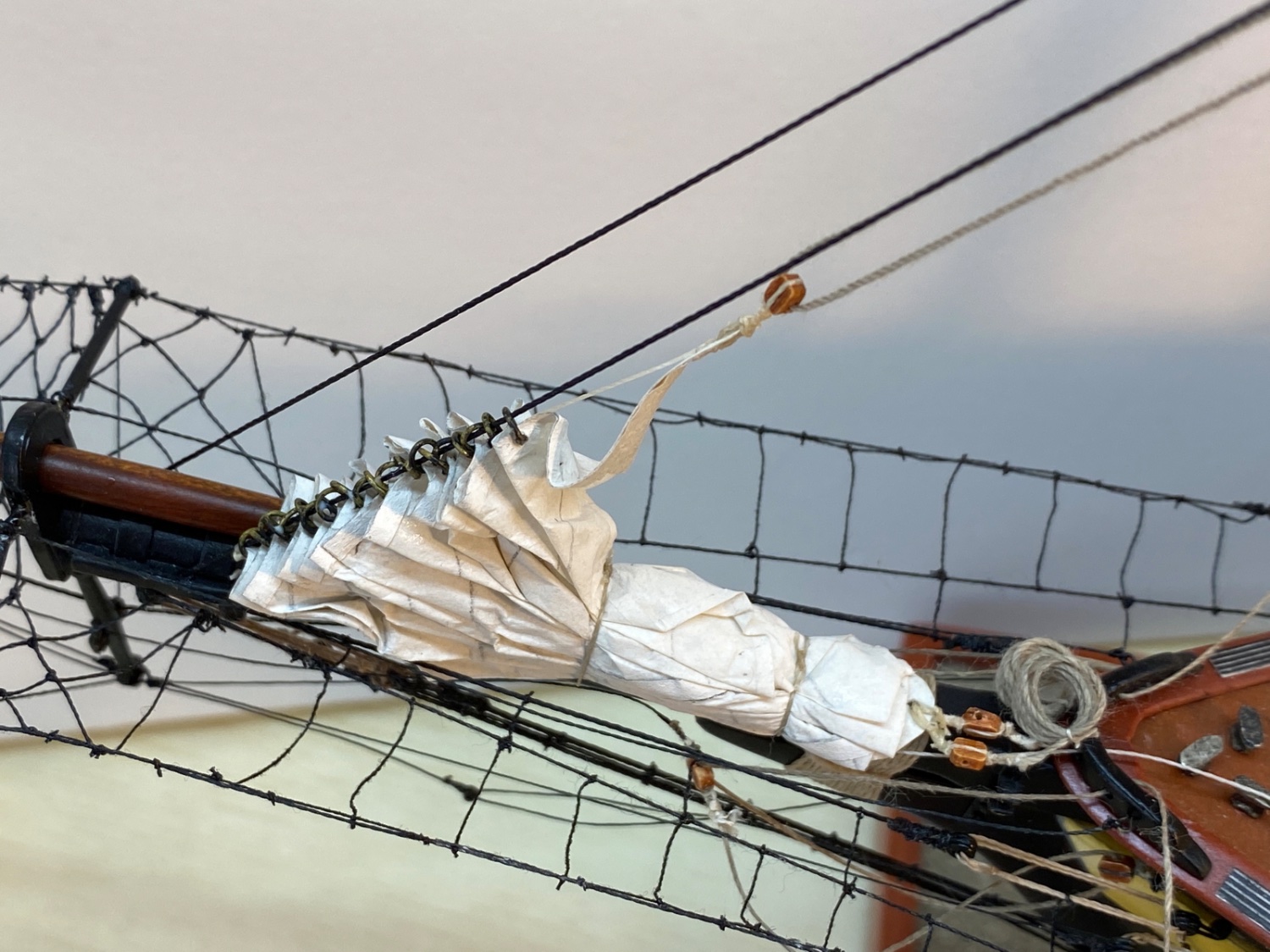
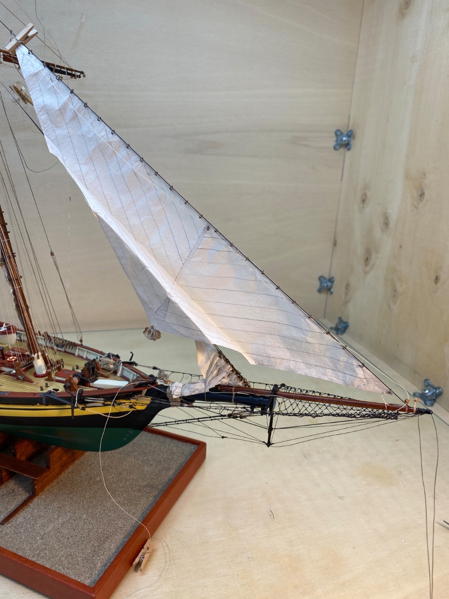
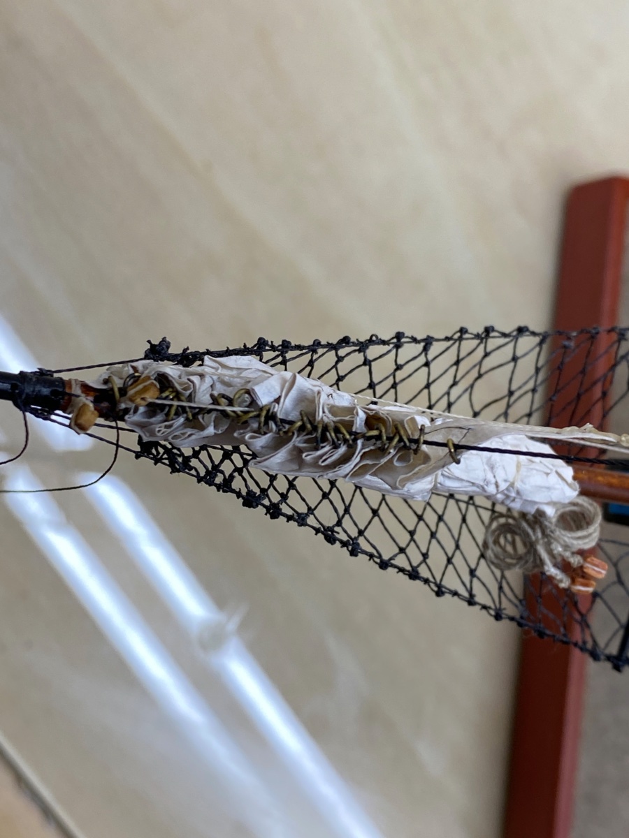
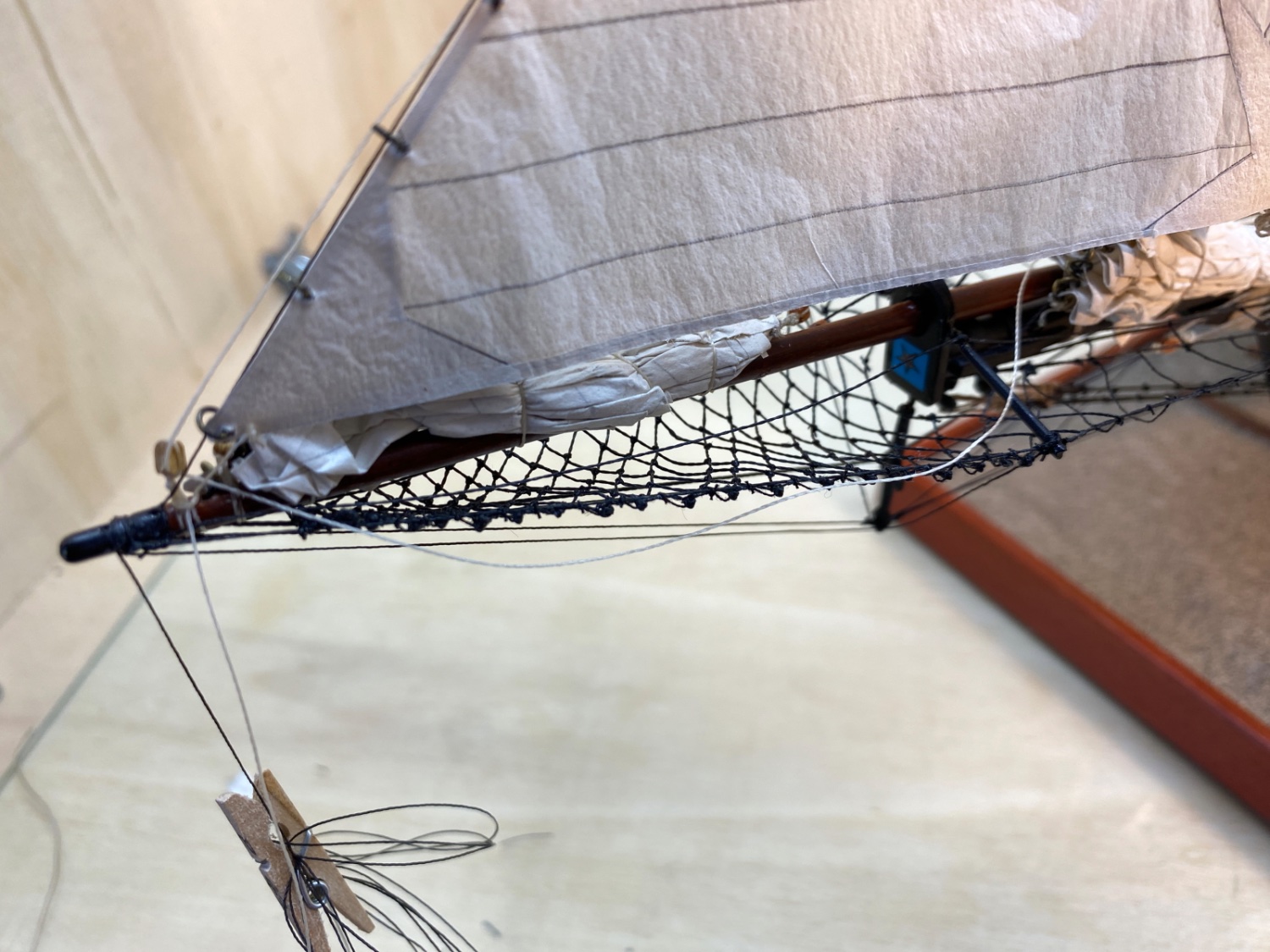
As the length of the base area is smaller than the sail's foot length I decided to fold the sail towards the fore stay first then started wetting and folding downwards. I hope the photos below explain the idea!


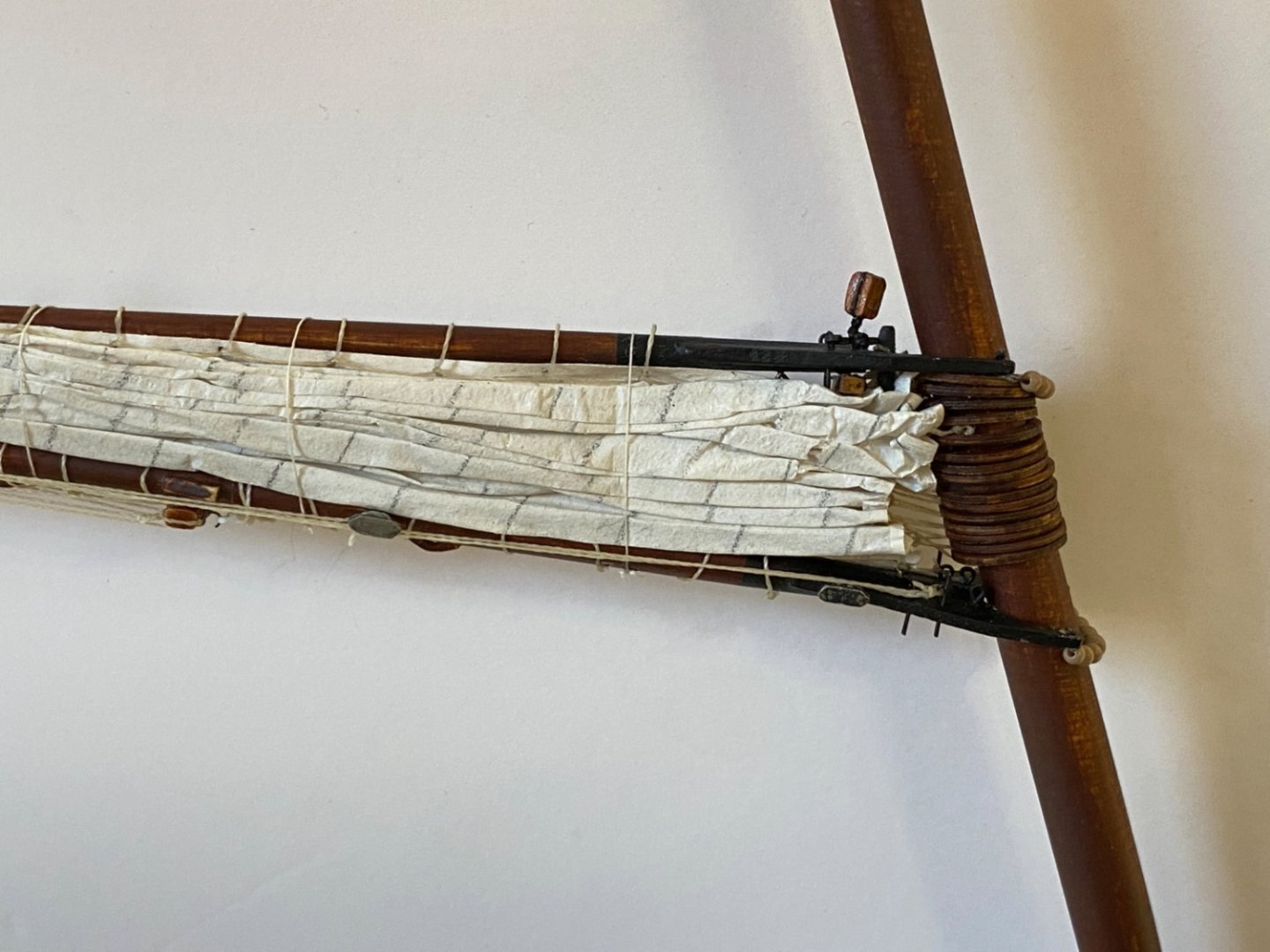
The furled sail was tied in two places. Diluted white glue was applied with a brush.


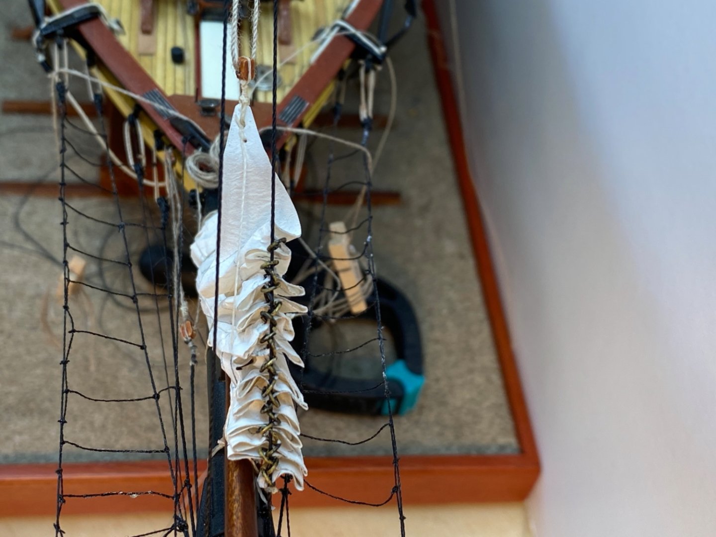

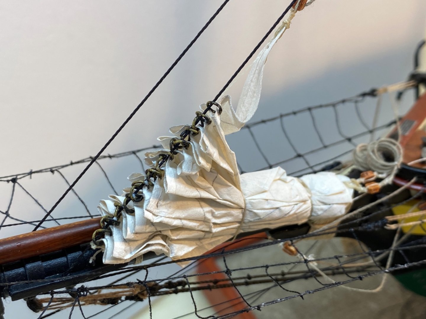

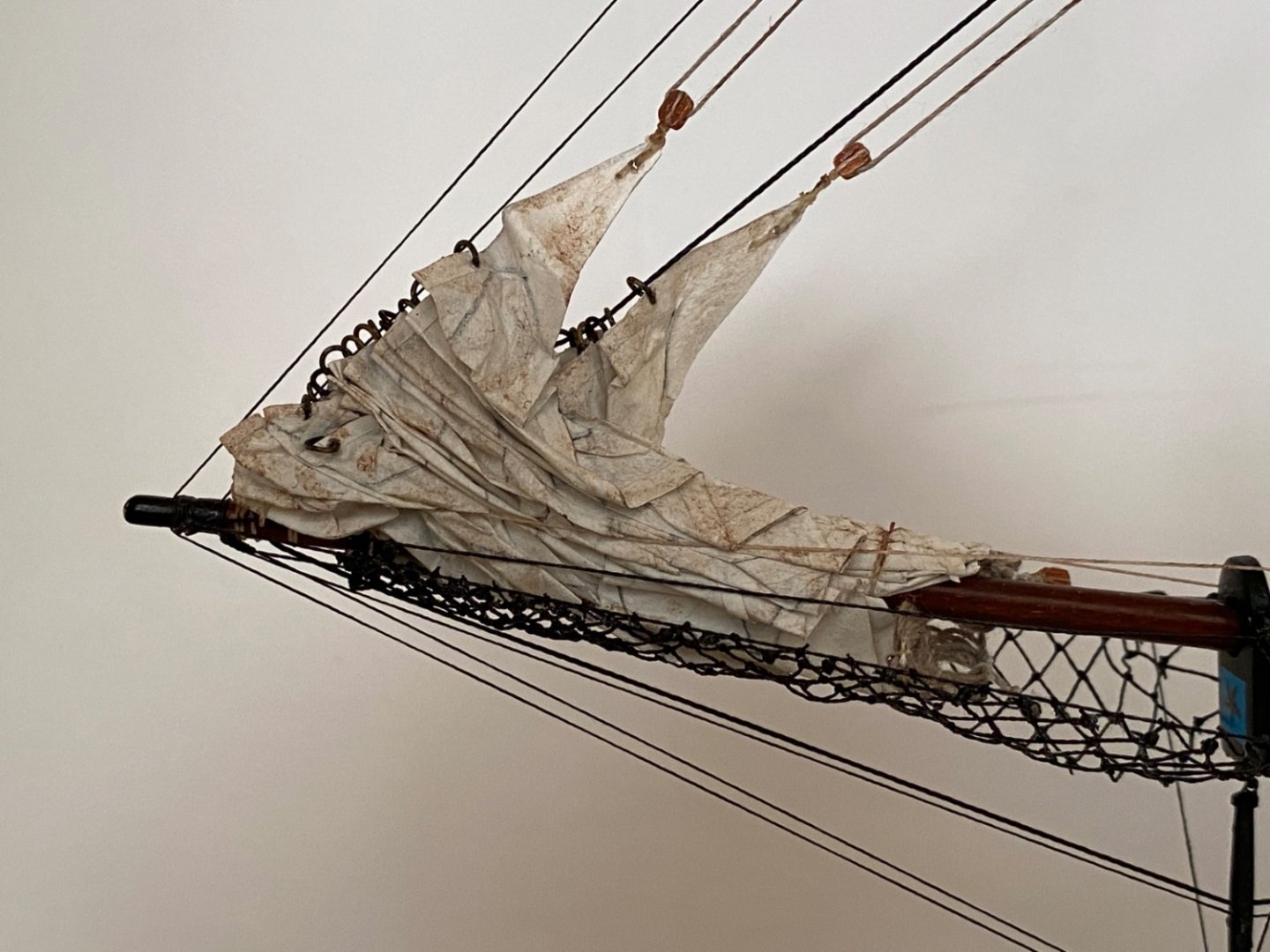
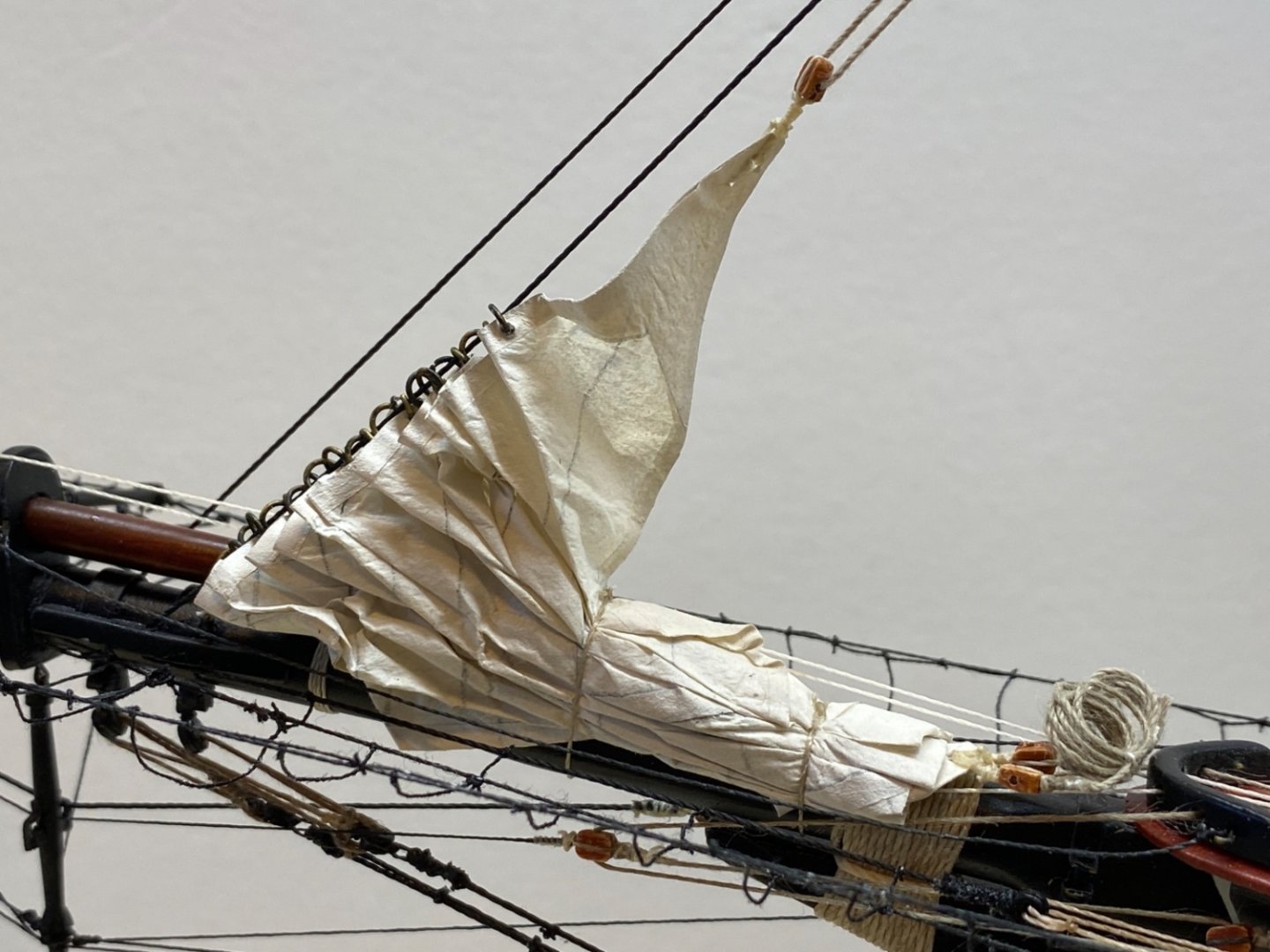
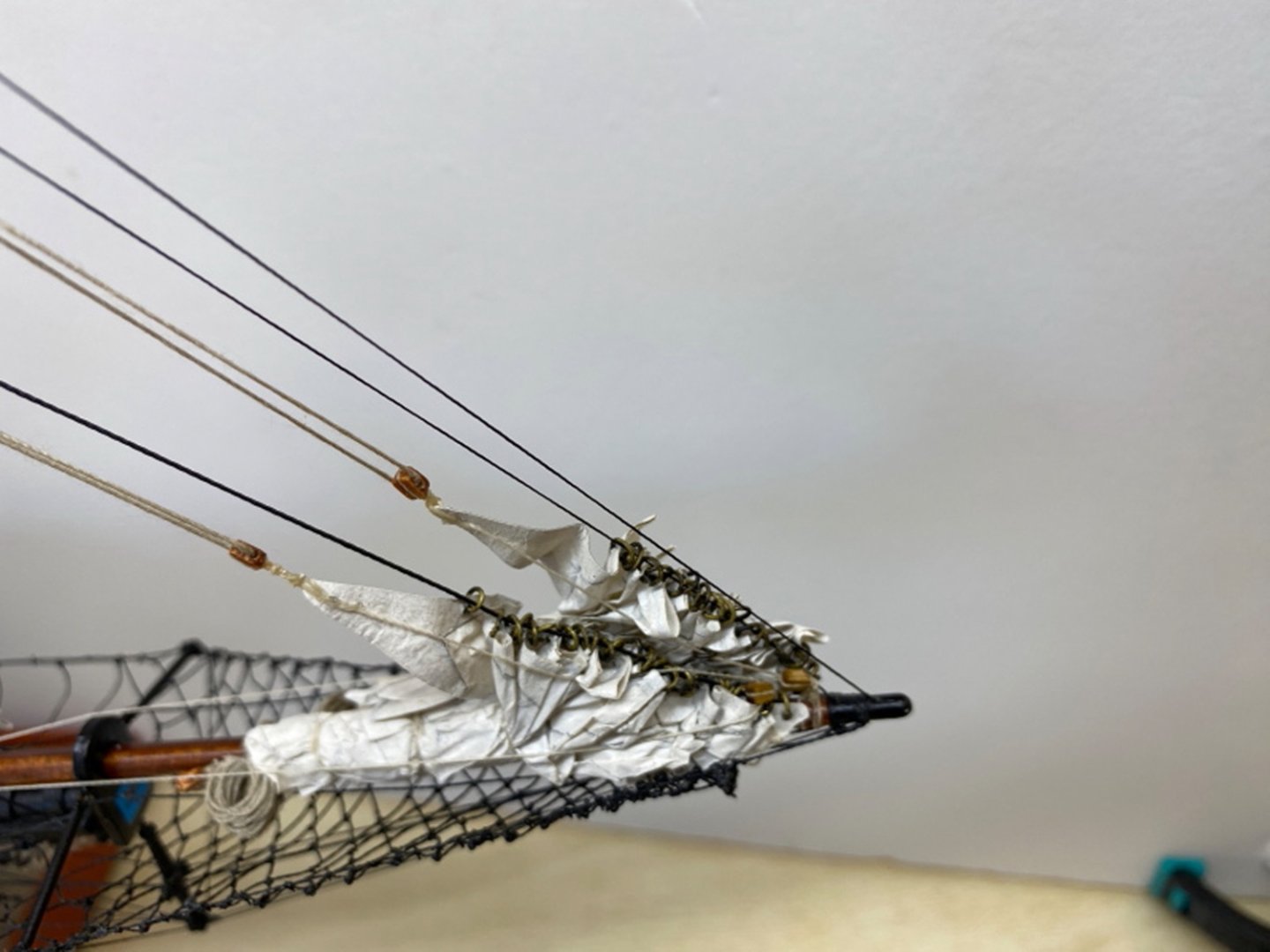
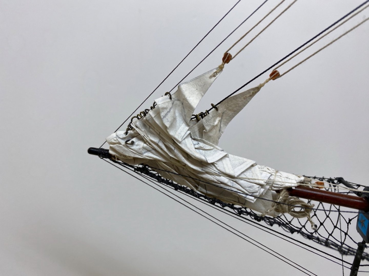
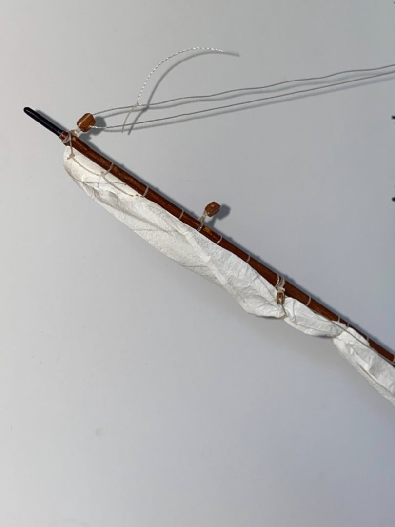
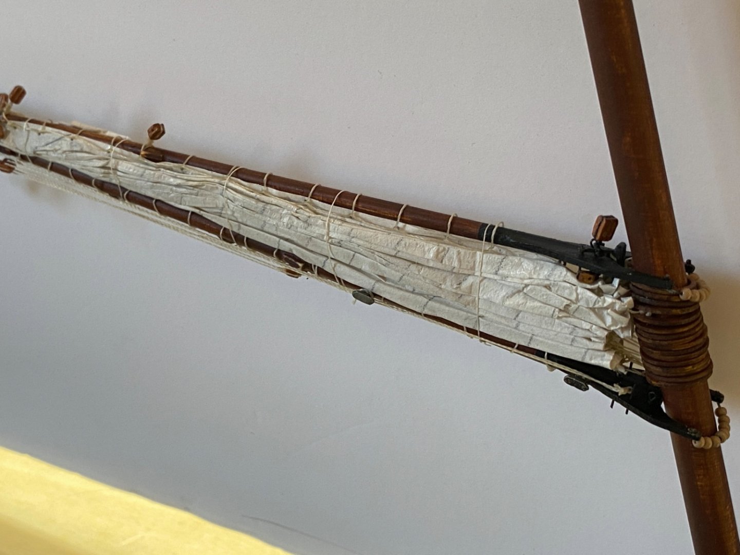
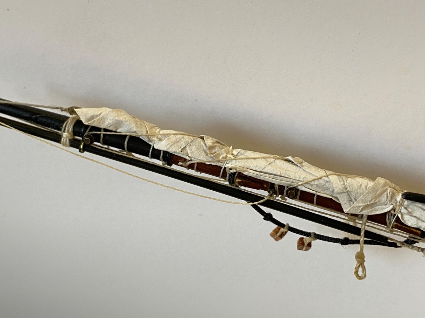
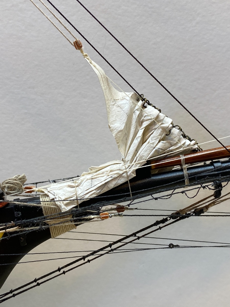
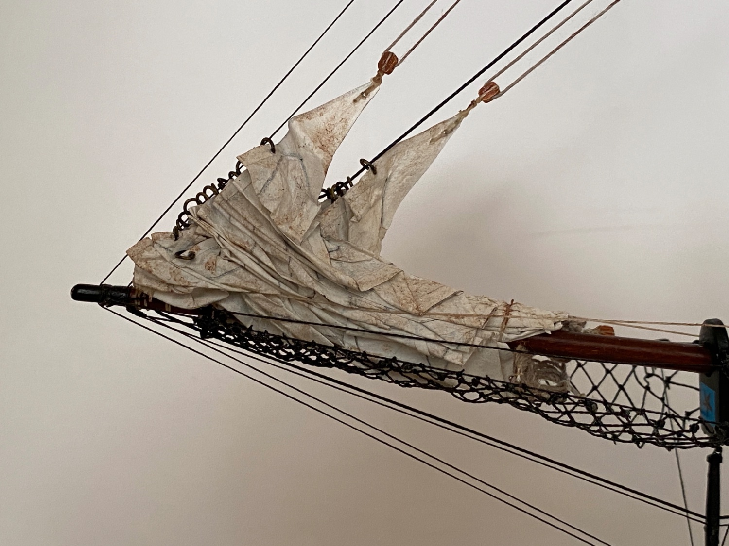
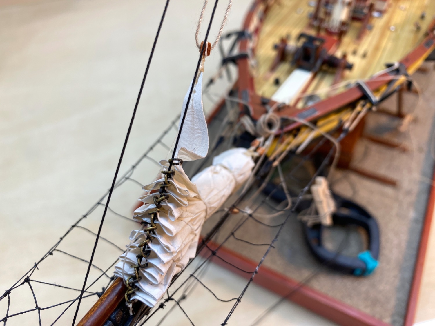
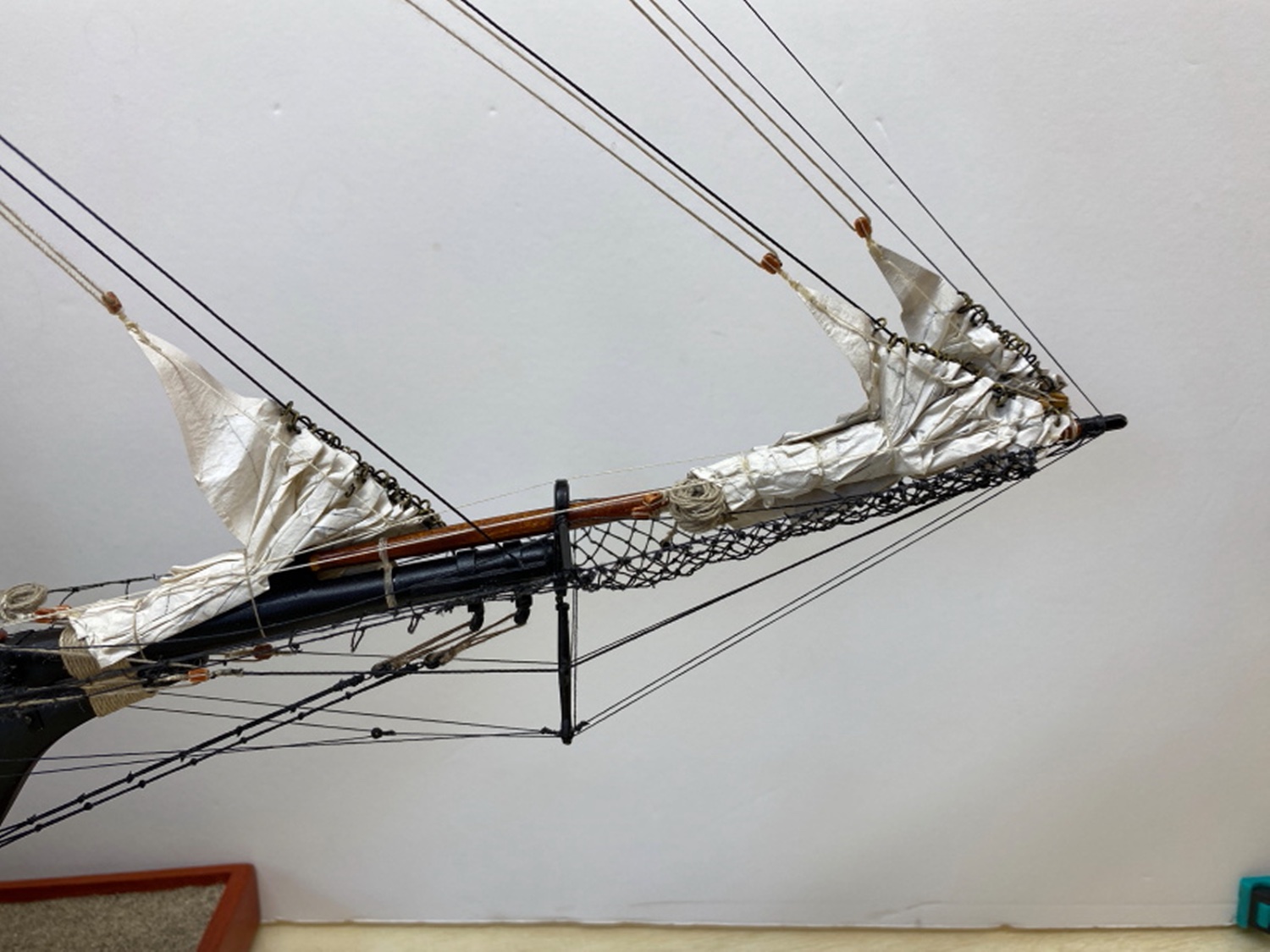
Jib was the next sail installed and furled following the steps like Forestay sail.


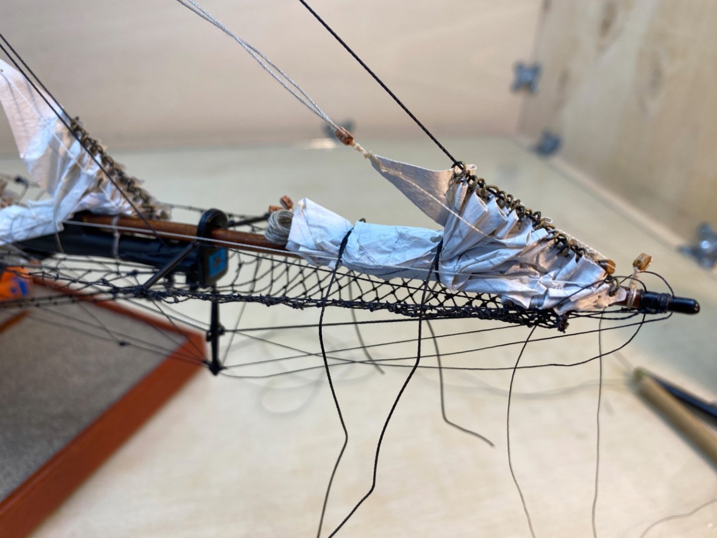
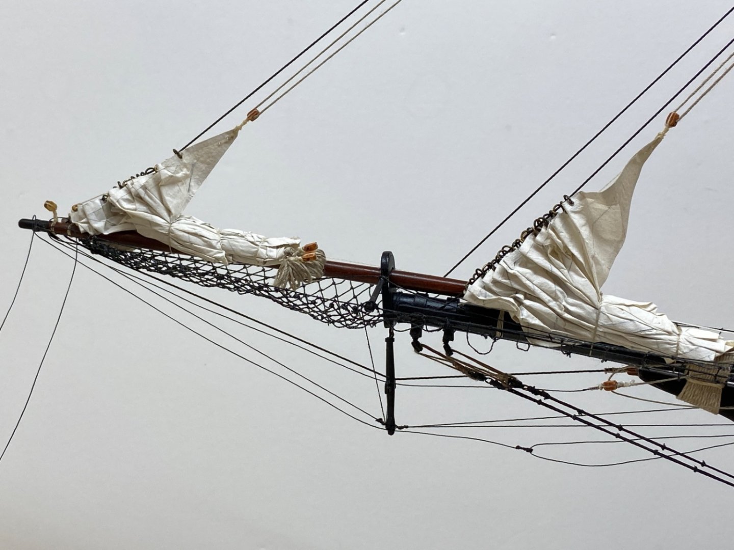


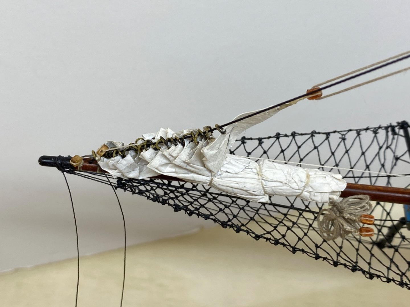

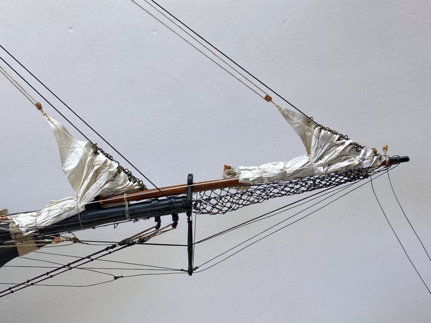

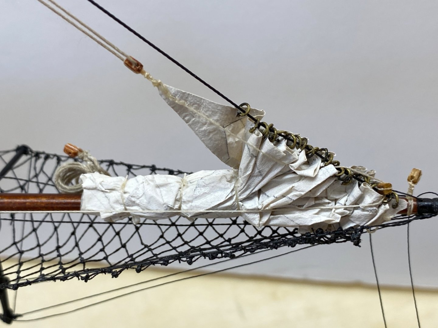

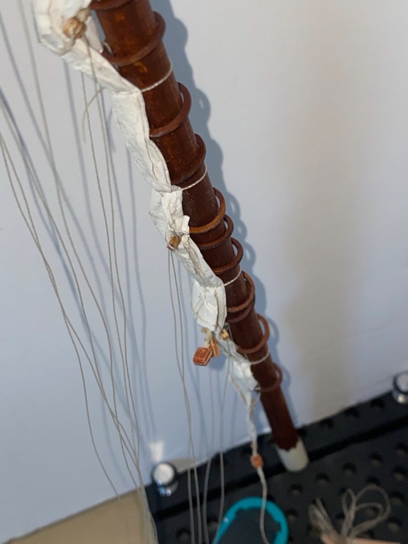
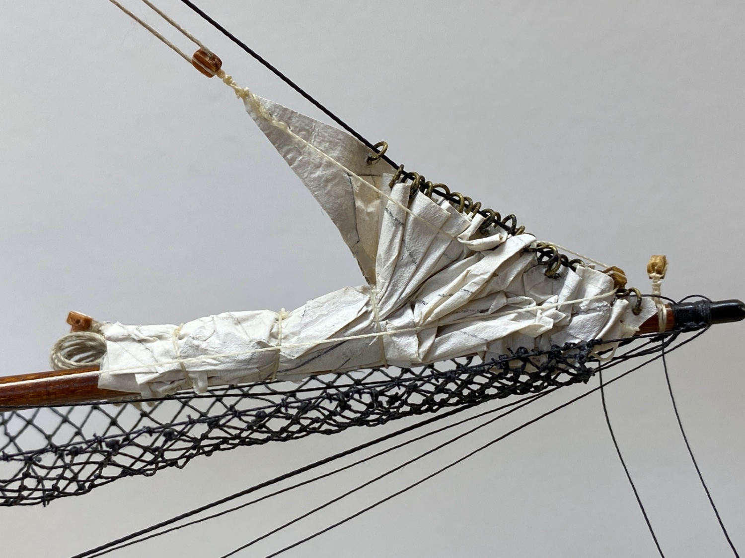
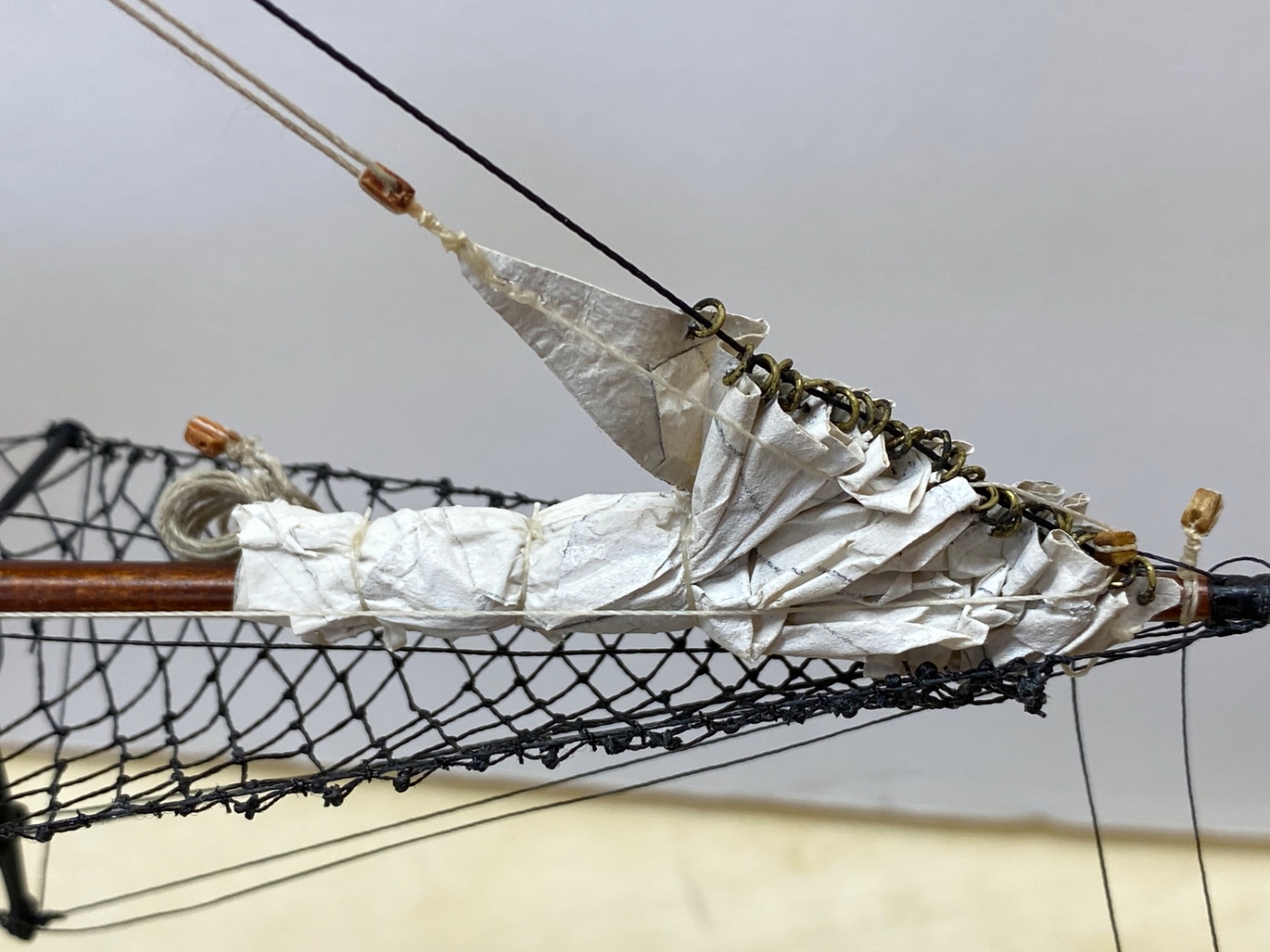
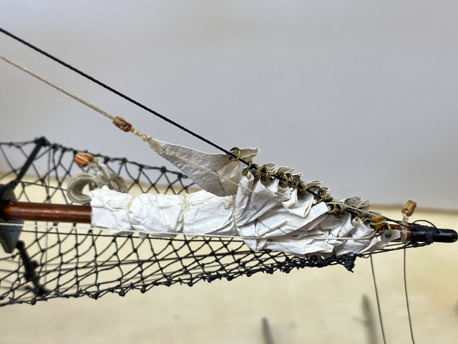
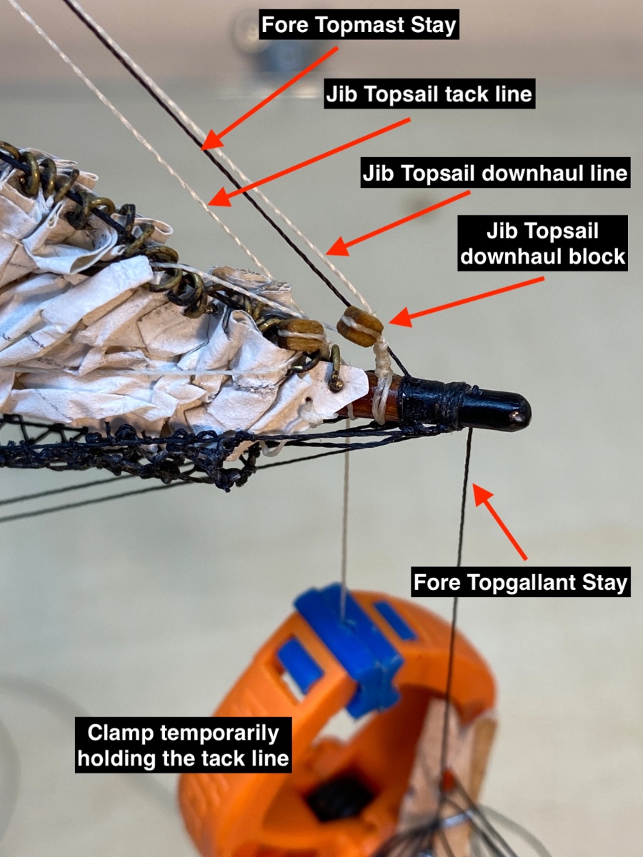
Finally Jib Topsail was installed and furled.


Here you see the Fore Topgallant Stay was also seized to Fore Topmast.


-
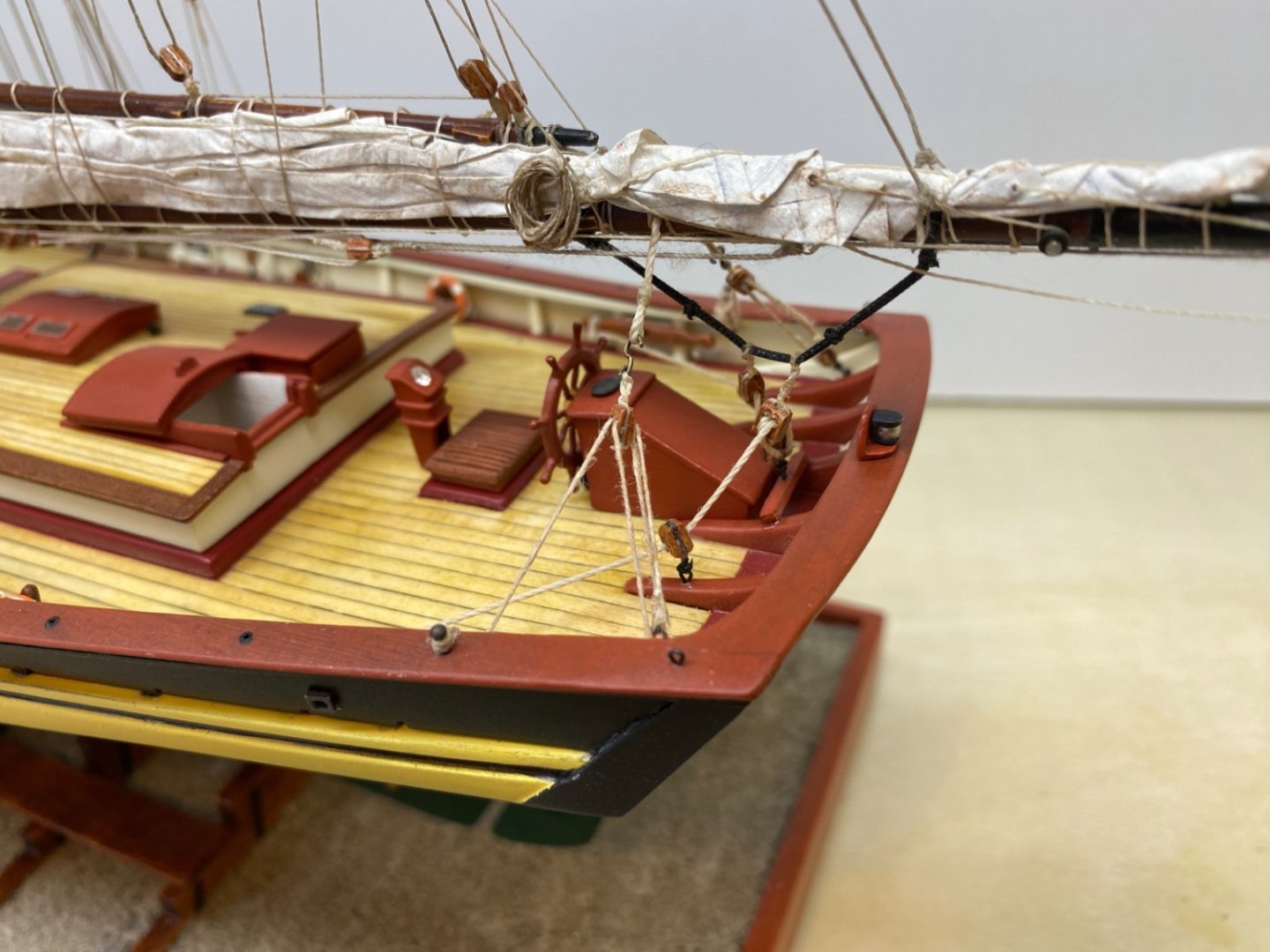
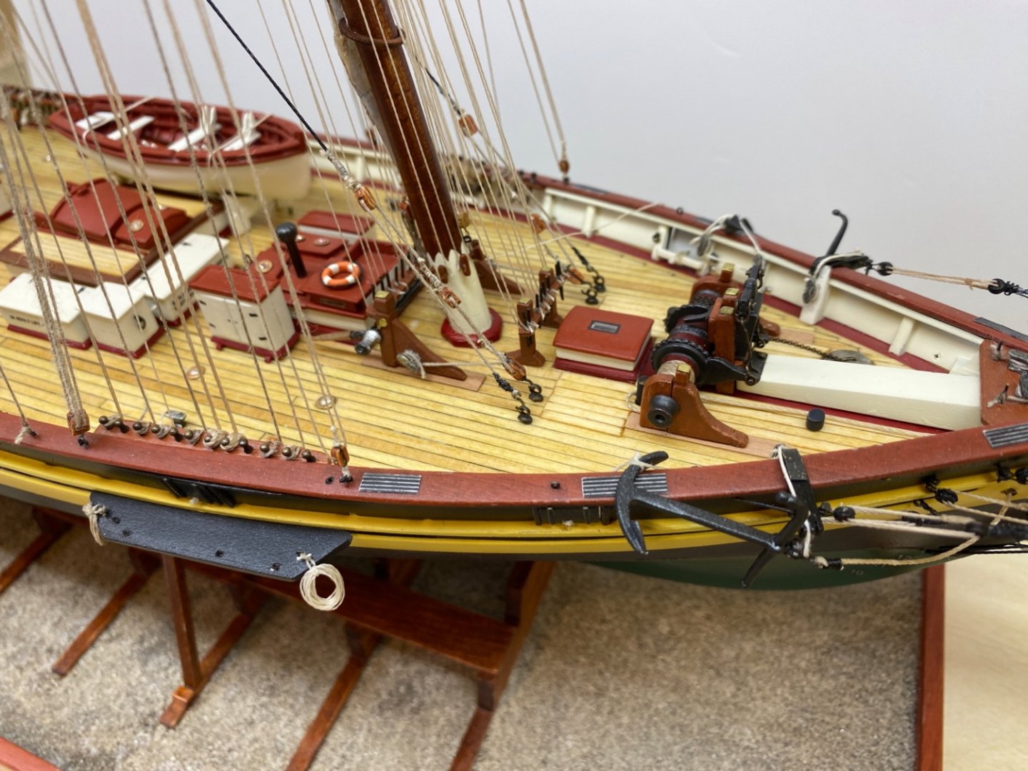
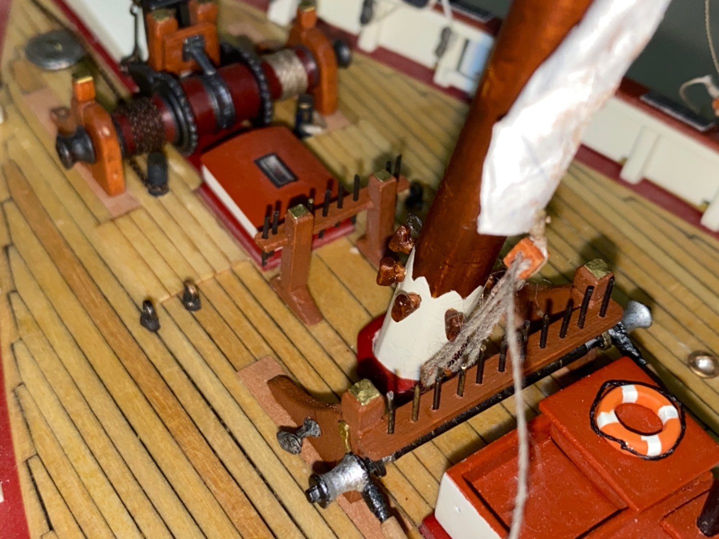
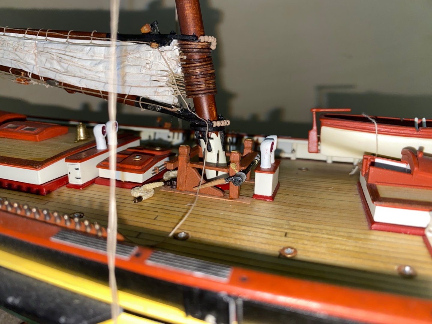
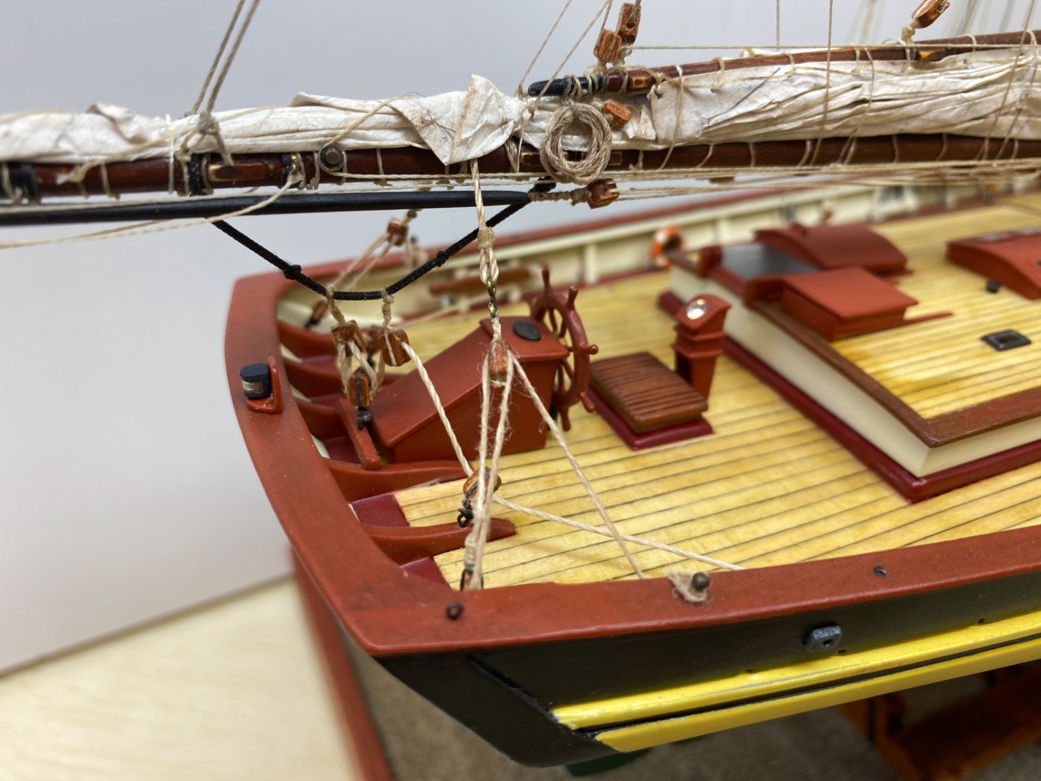
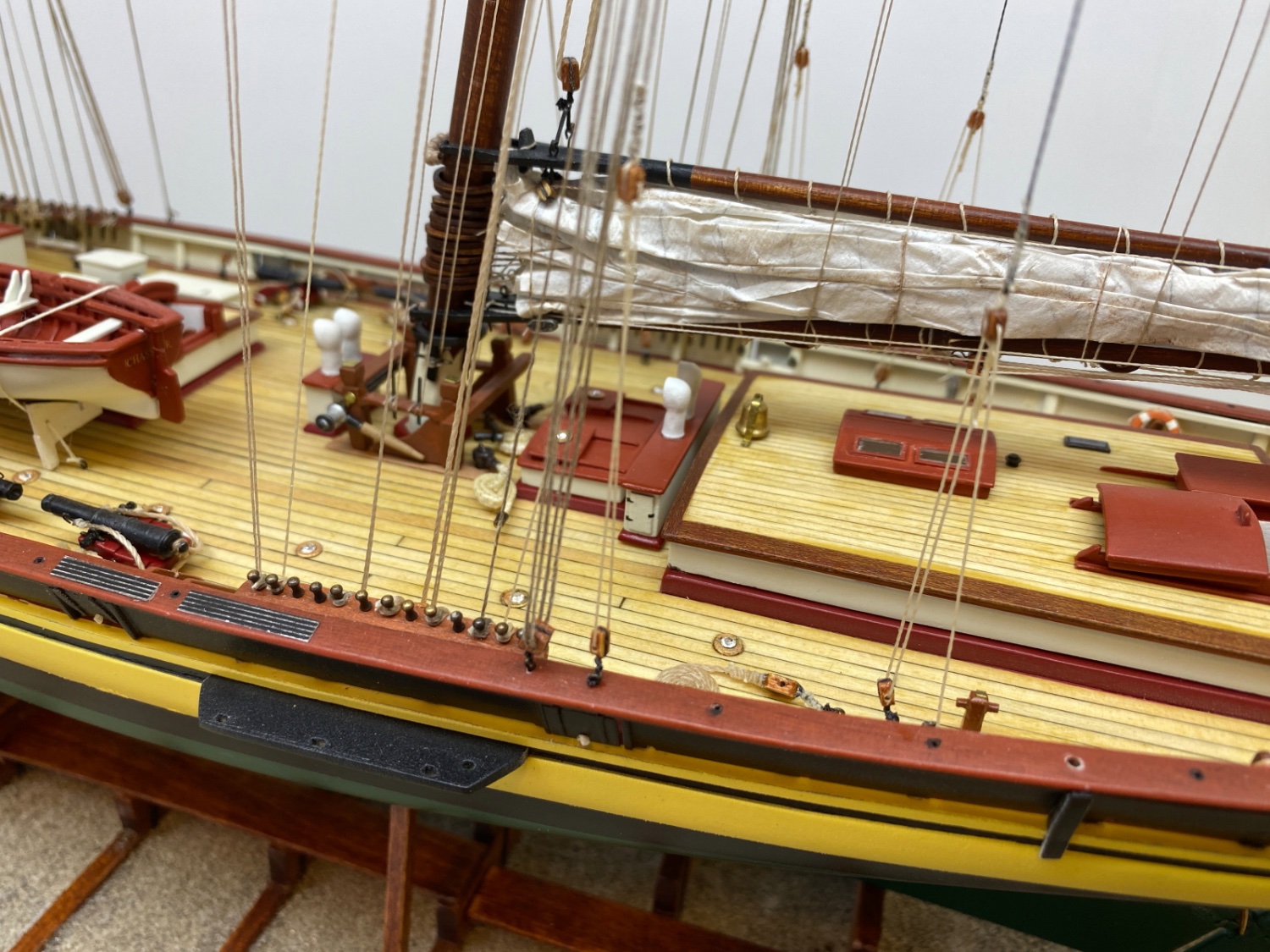
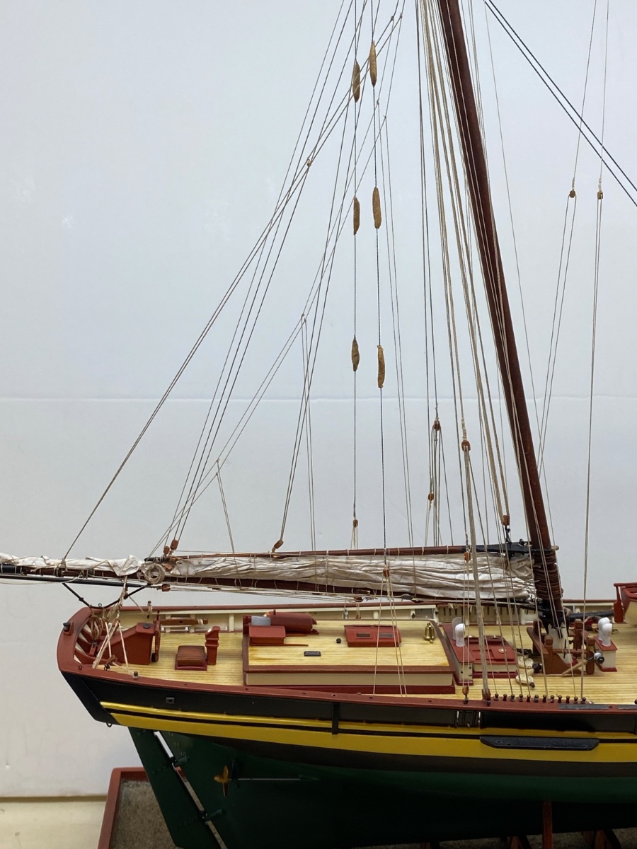
I continued with the running rigging lines belaying at the fife rail pins at the bases of the masts and the running rigging of the main boom and main sail at aft deck.
Here are some photos of the running rigging lines of the fore mast.
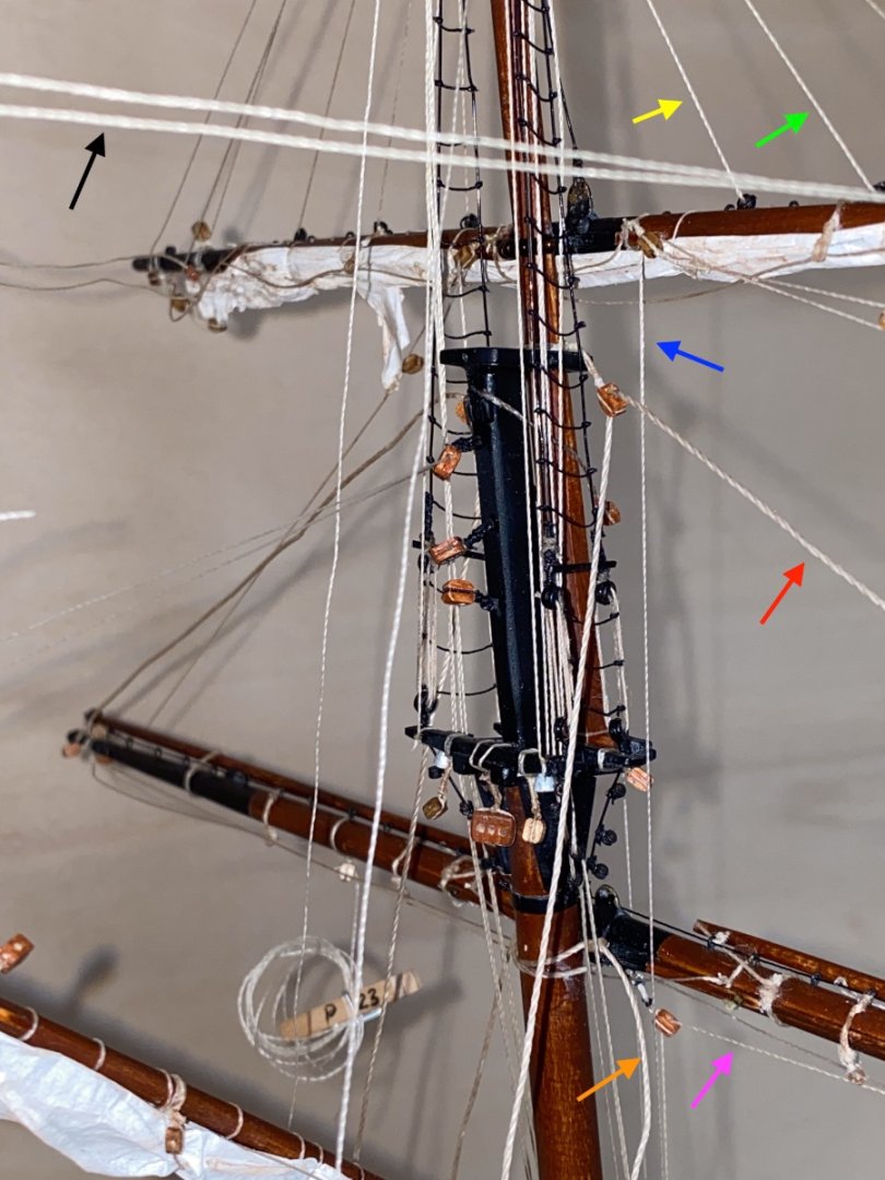
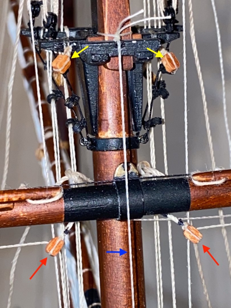
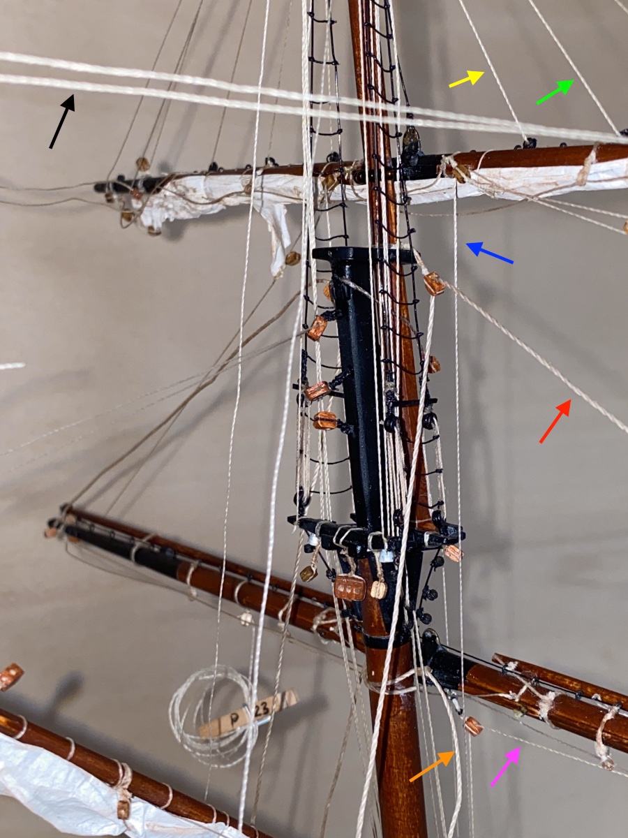
In the first photo you see the mast head area and the two yards. Lines indicated with arrows are all starboard side.
Red arrow Lower yard lift line
Blue arrow Topsail clew line
Yellow arrow Topsail inner buntline
Green arrow Topsail leech line
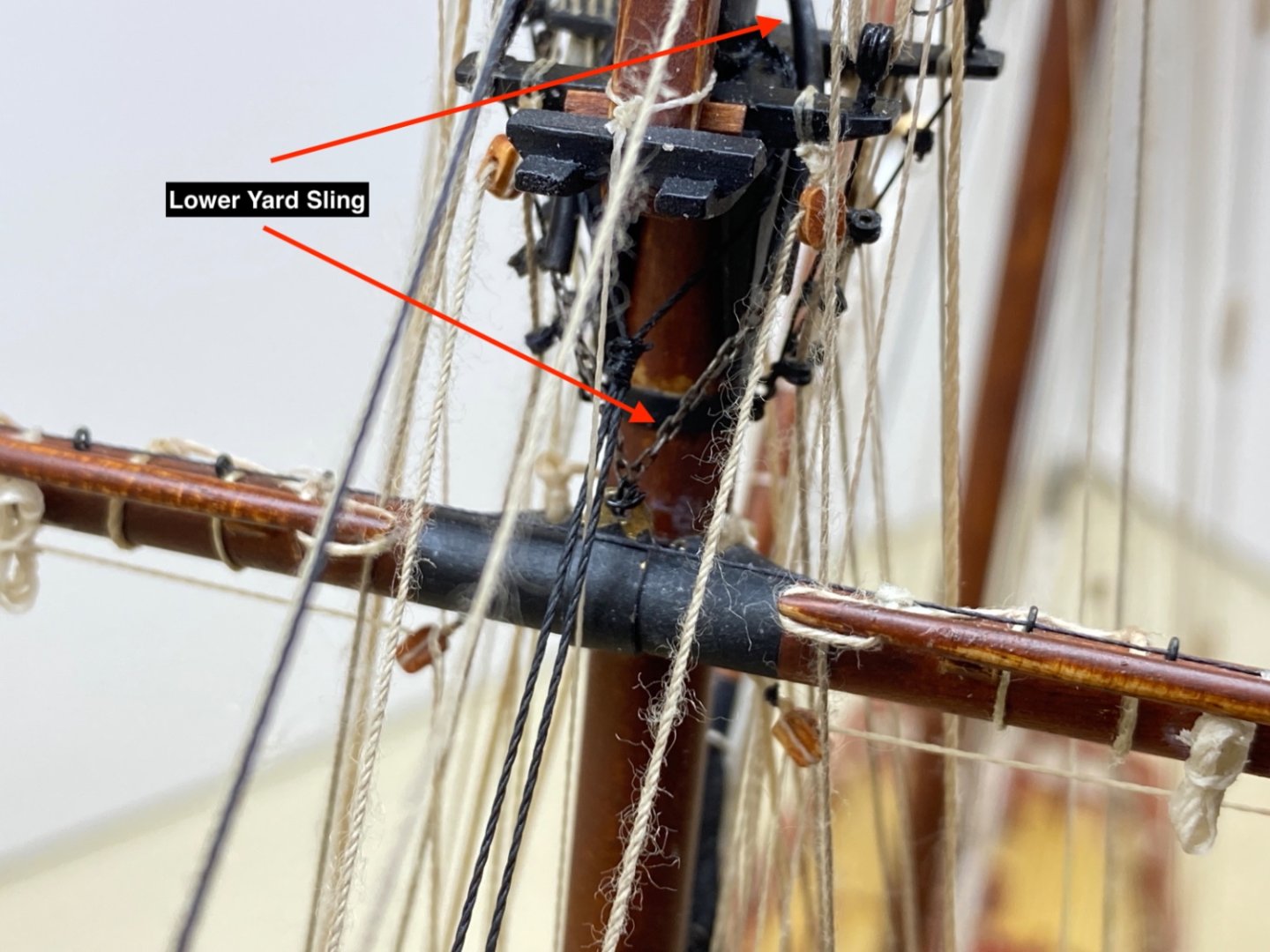
Orange arrow Lower yard truss
Violet arrow Topsail sheet line
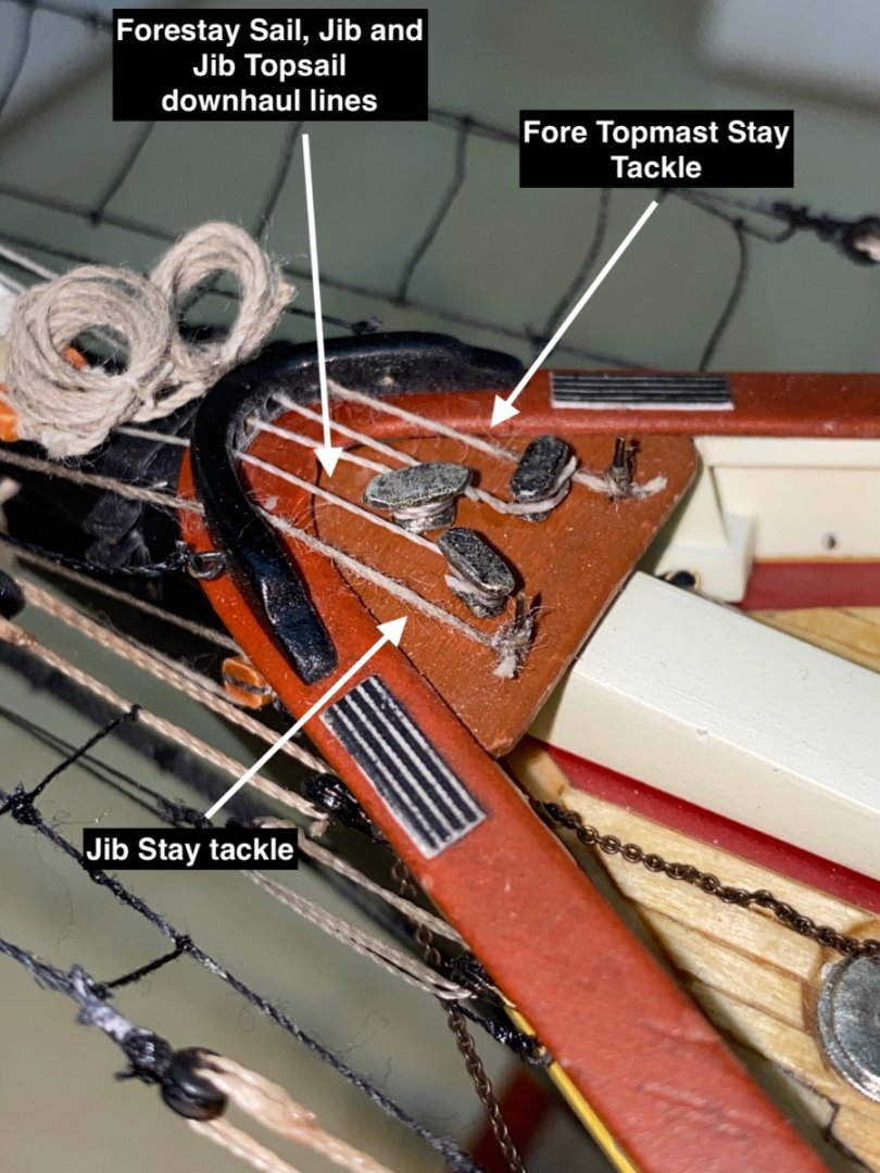
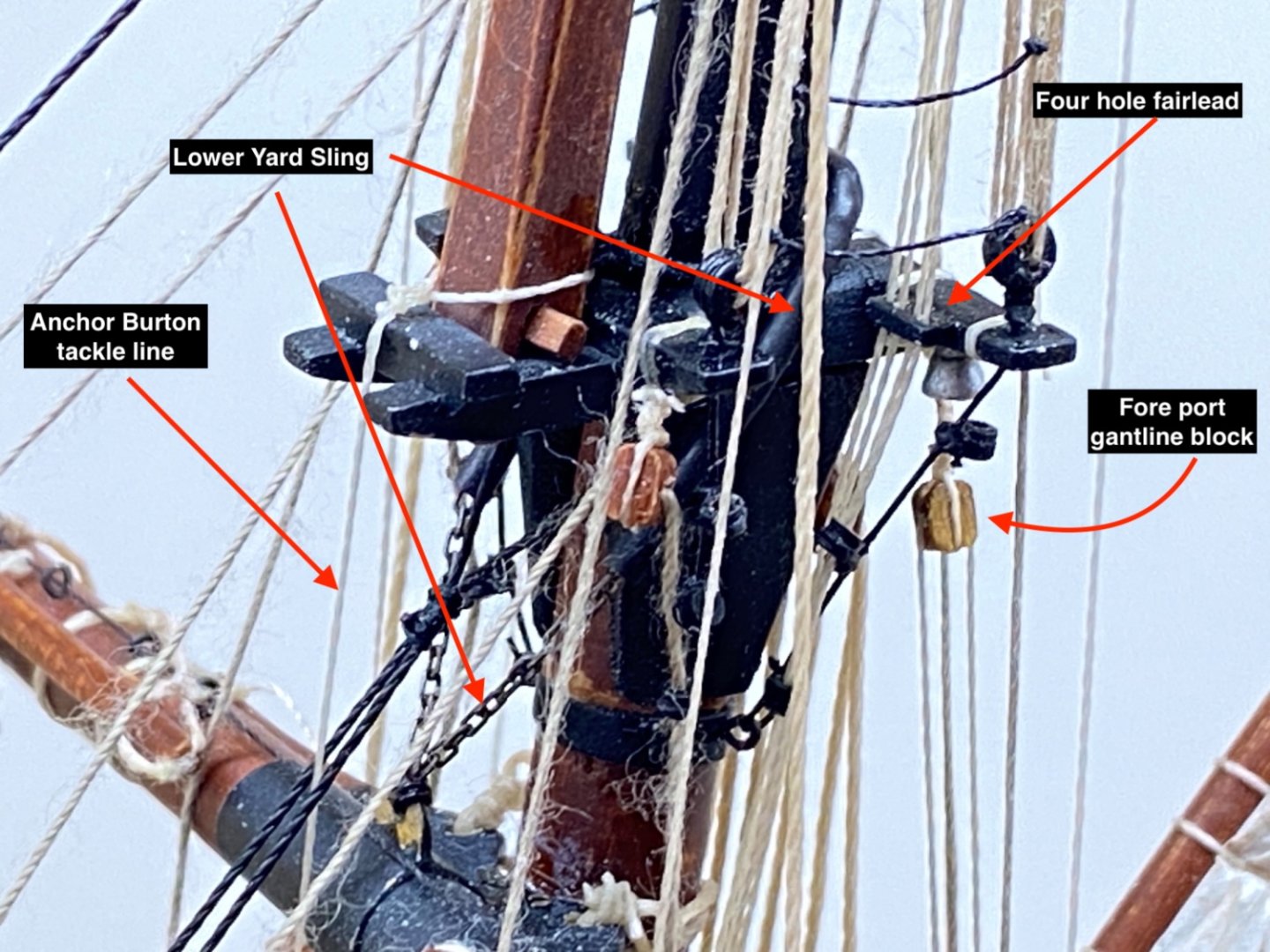
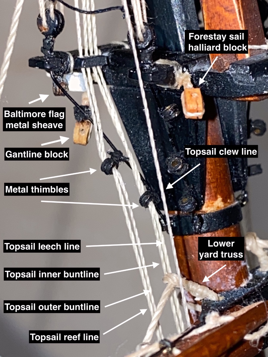
Fore Mast head section from starboard oblique view. Here you see the four lines passing through the holes of the fairlead block at the aft crosstrees and later pass through two metal thimbles in pairs. These lines were belayed at the pin rails in front of the foremast.

Same area fore to aft view
Yellow arrows Forestay sail halliard blocks
Blue Arrow Anchor Burton line
Red arrows Topsail sheet line.
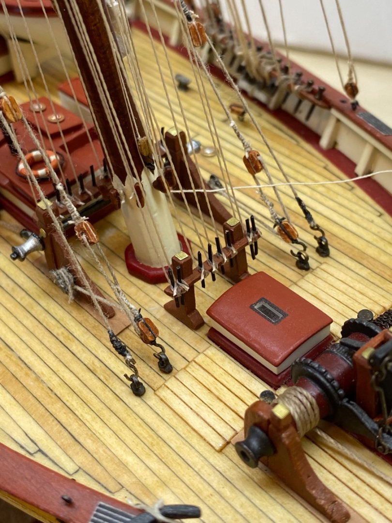
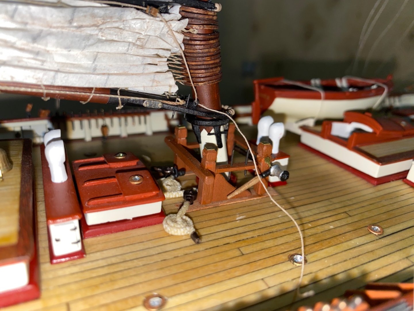
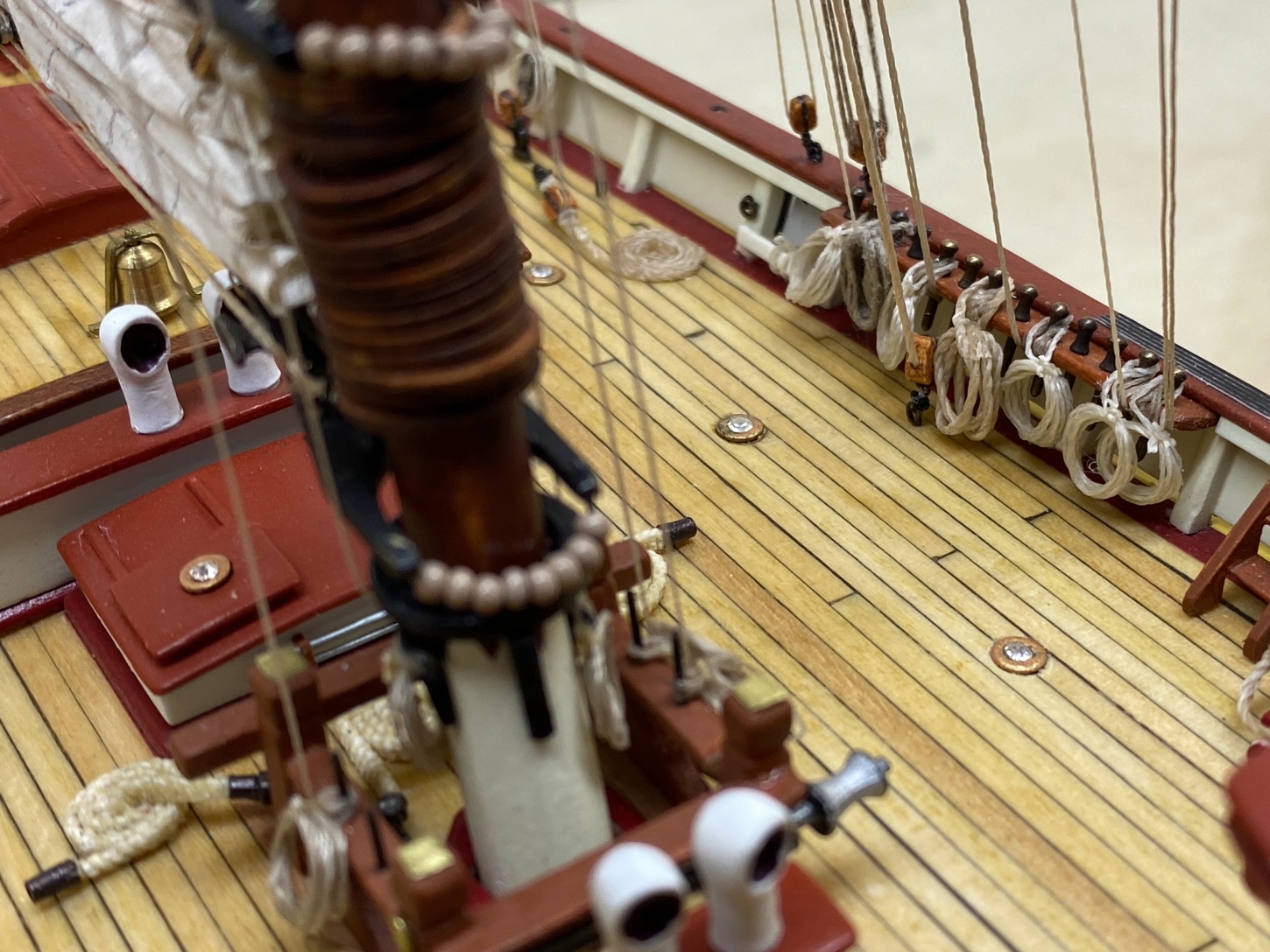
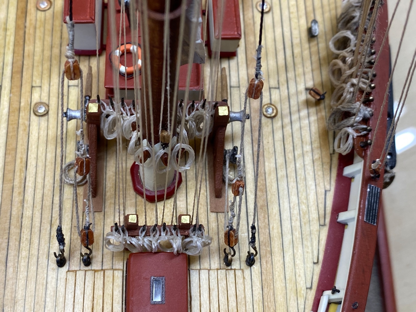
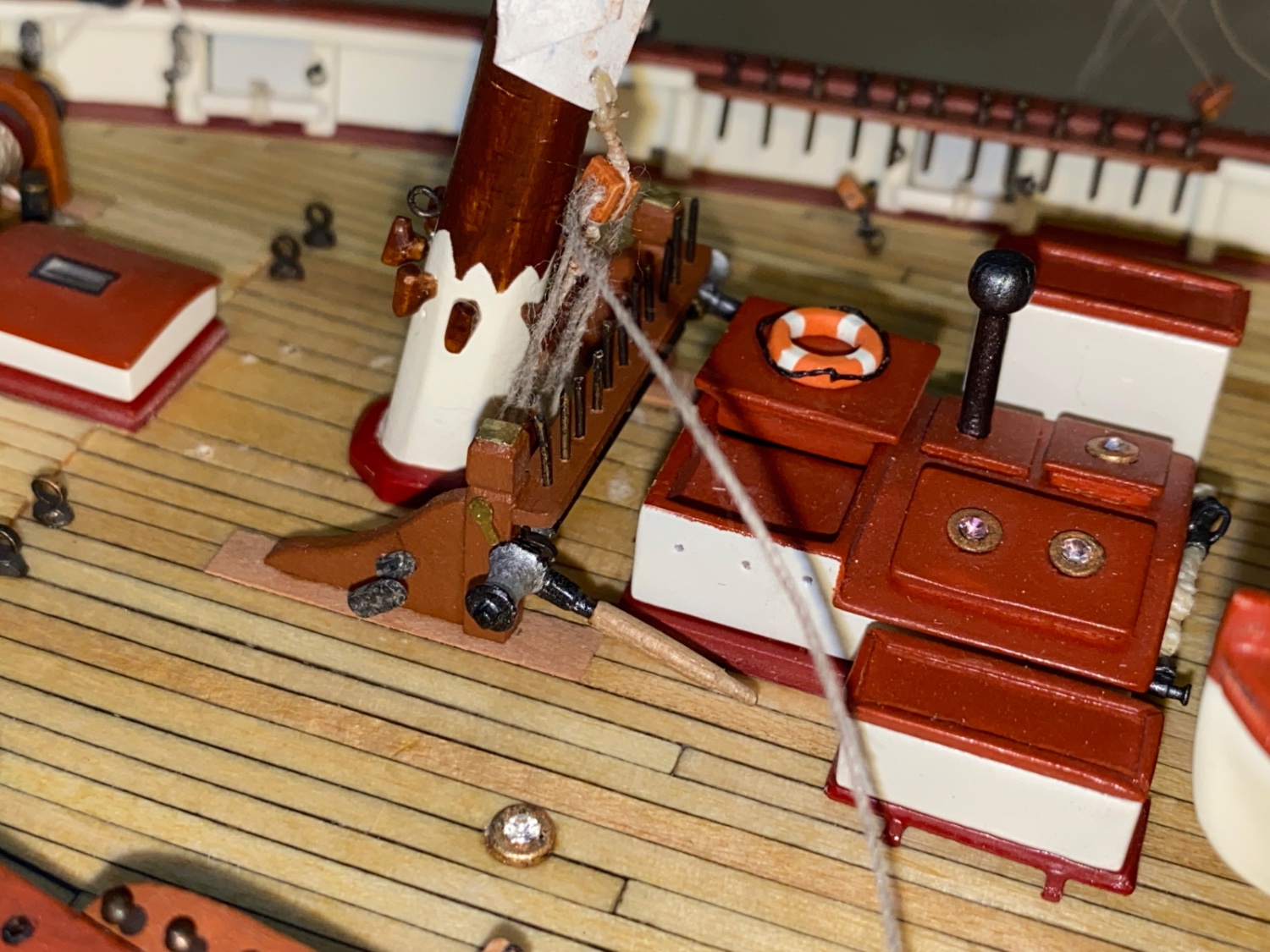
Base of the foremast. Wide angle view of the fife rails.
Closeup view of the foremast base. All the brail lines of the foresail were belayed at the pins of the fife rails located at the aft of foremast base.
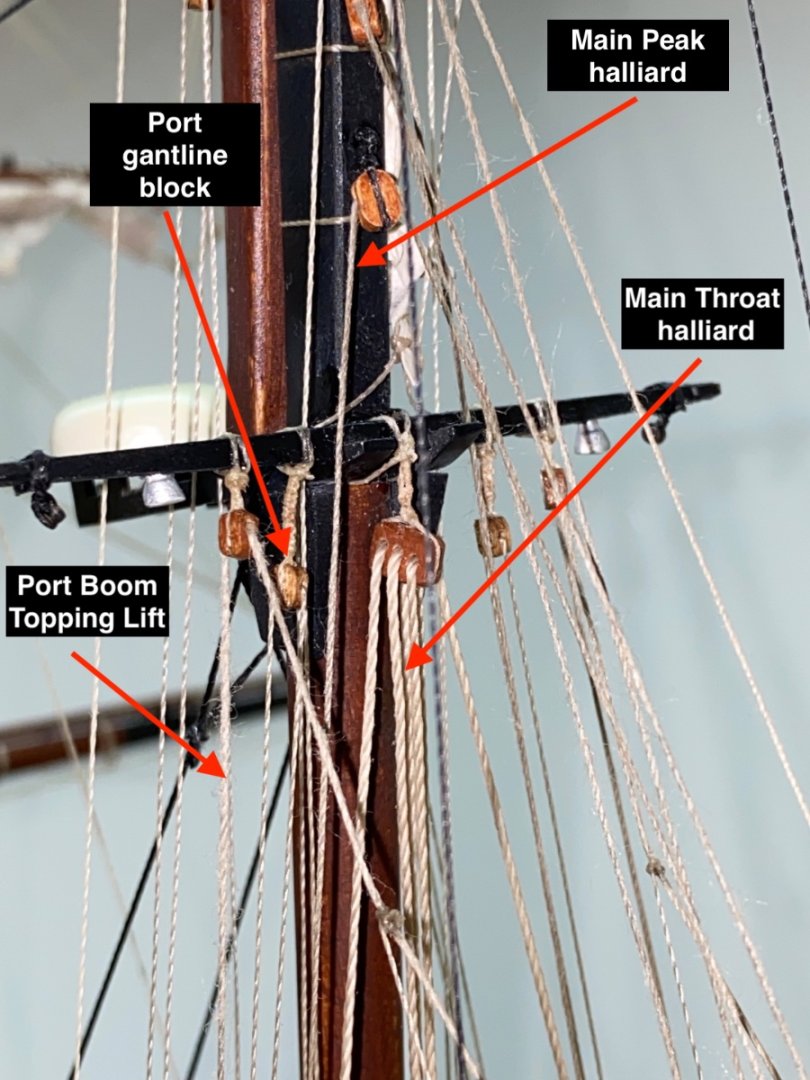
Base of the main mast port side view
Starboard side view

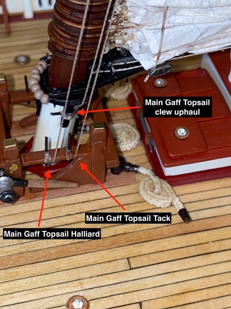
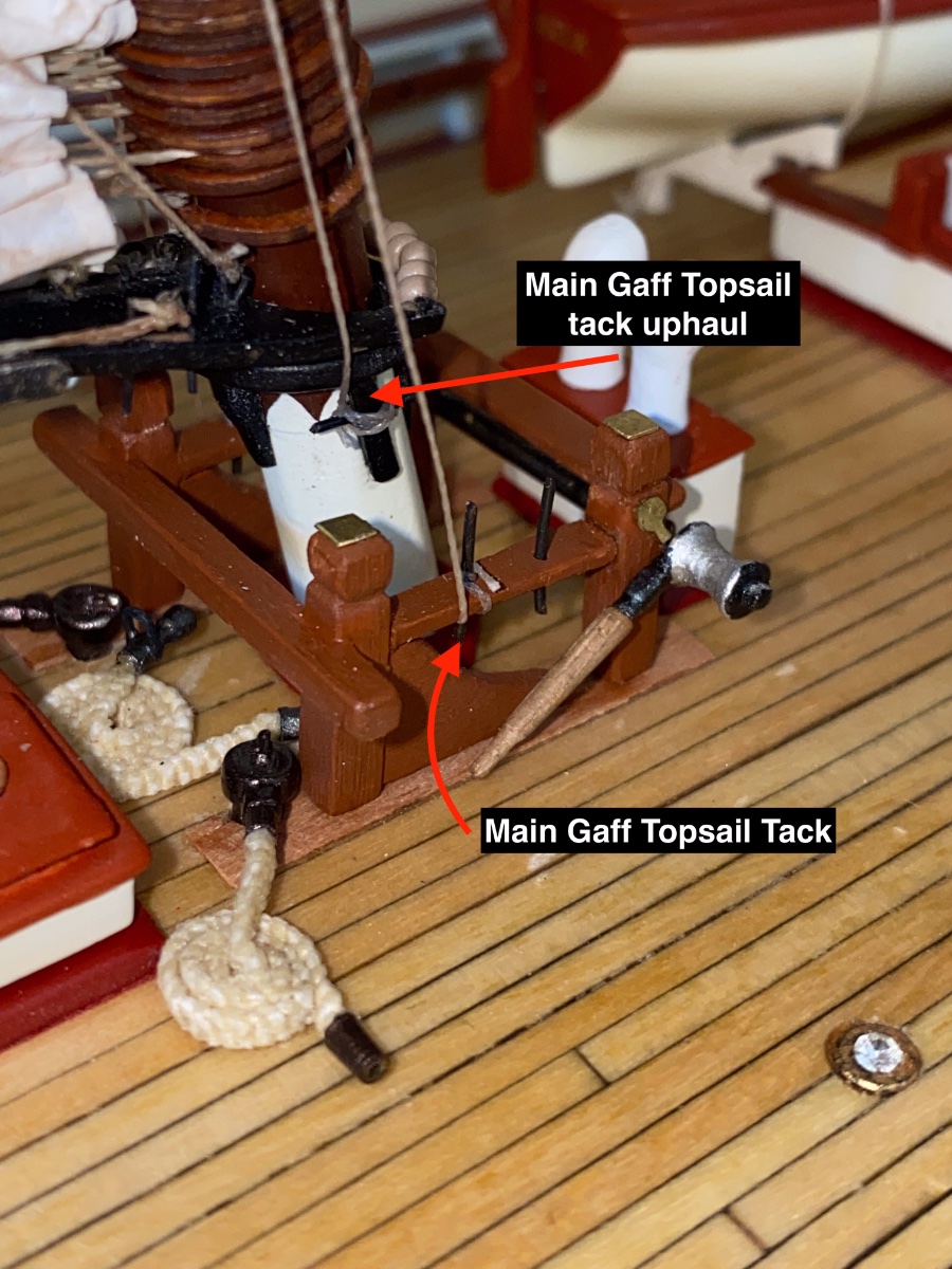
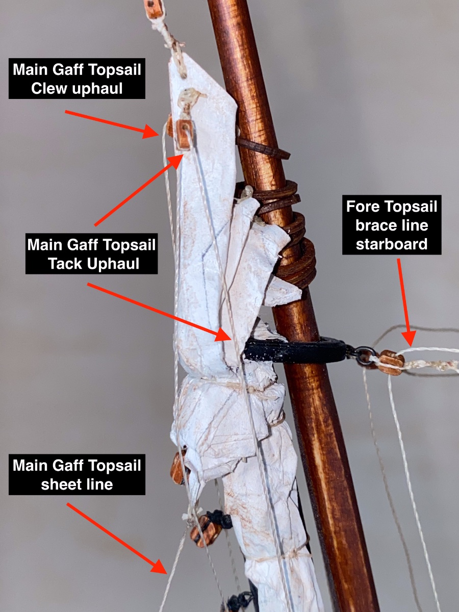
Main Gaff Topsail running rigging
Port side view
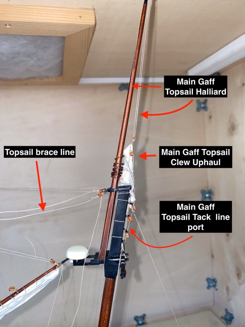
Starboard side view

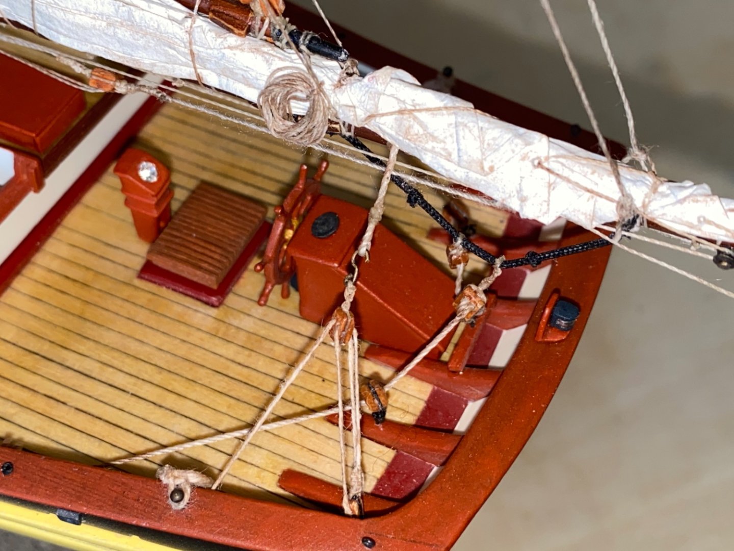
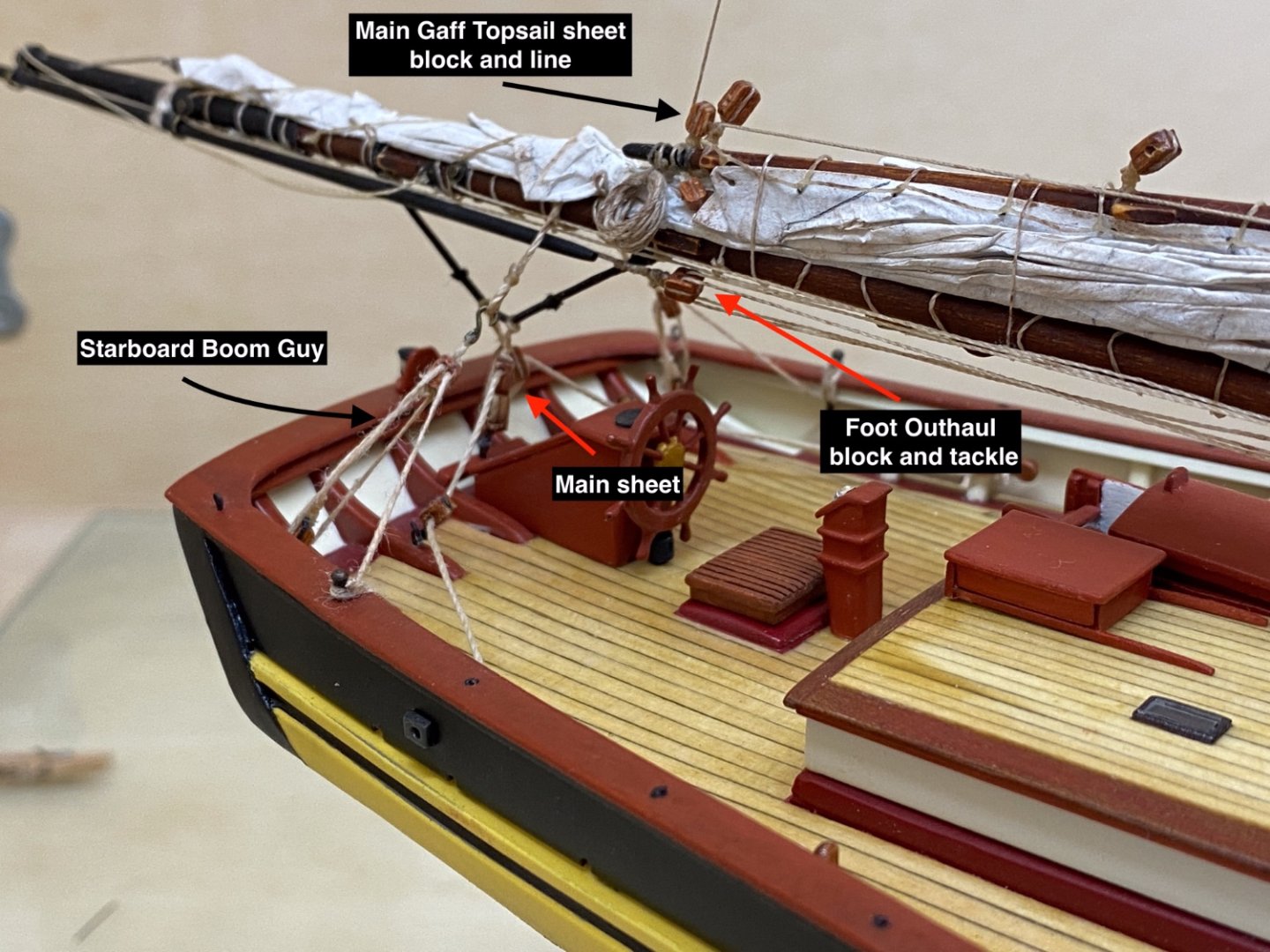
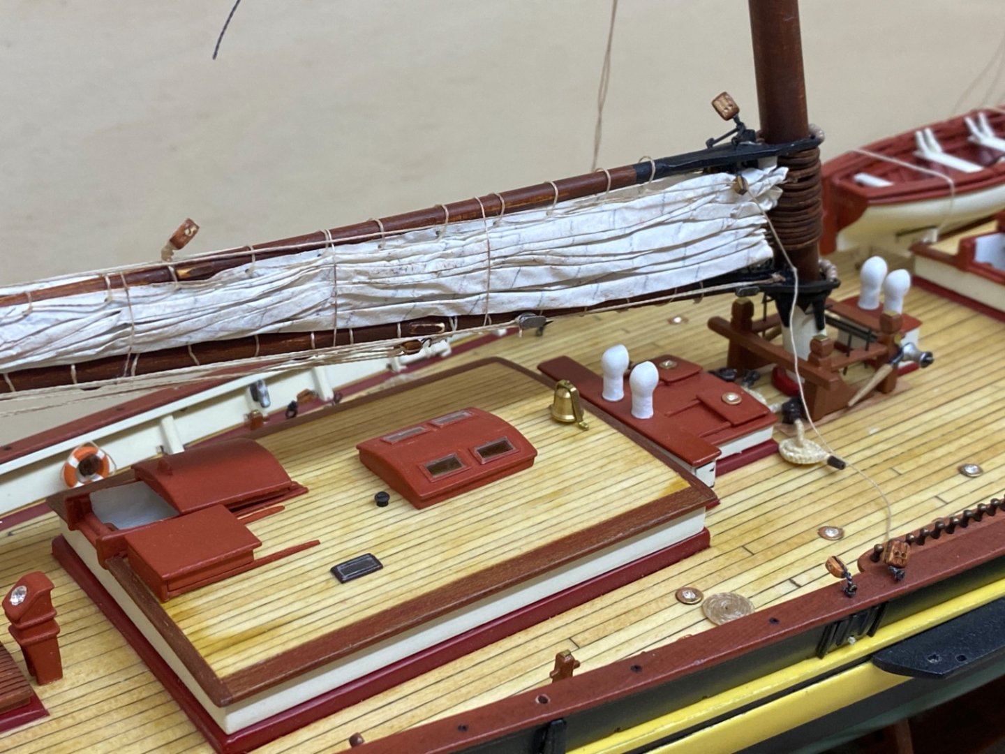
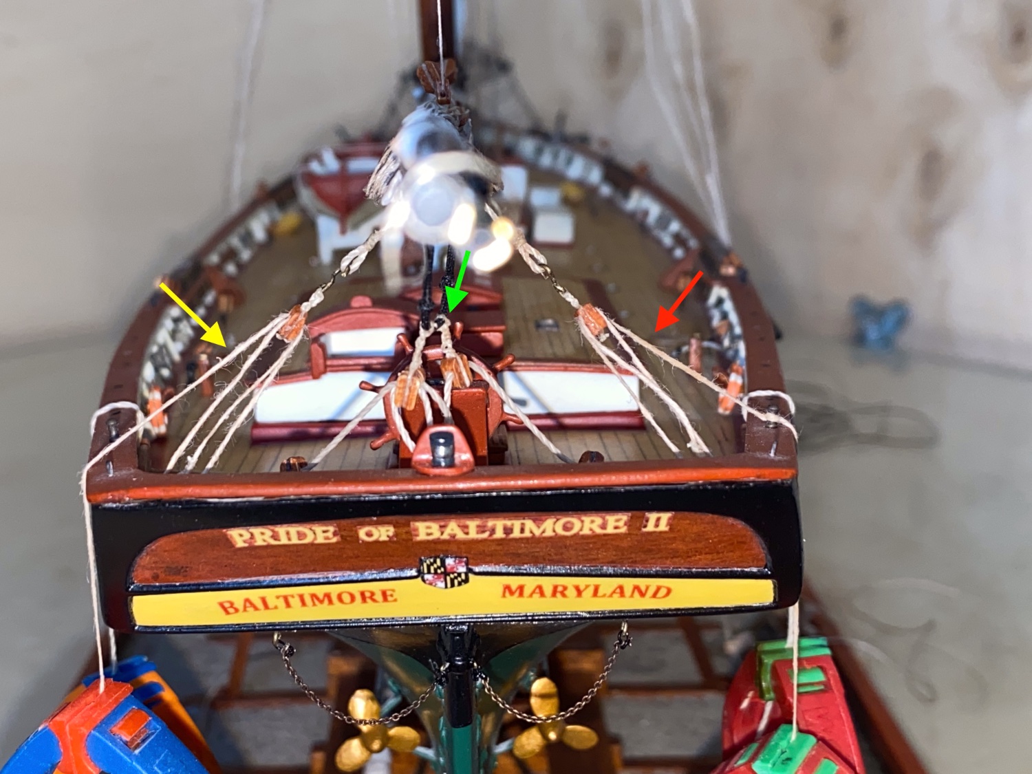
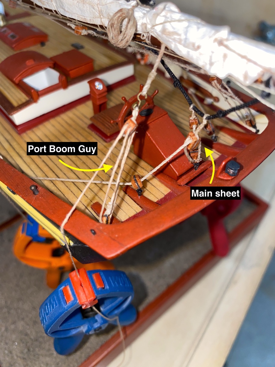
Running rigging of the main boom and main sail.
View from aft to fore
Port side view

Starboard side view
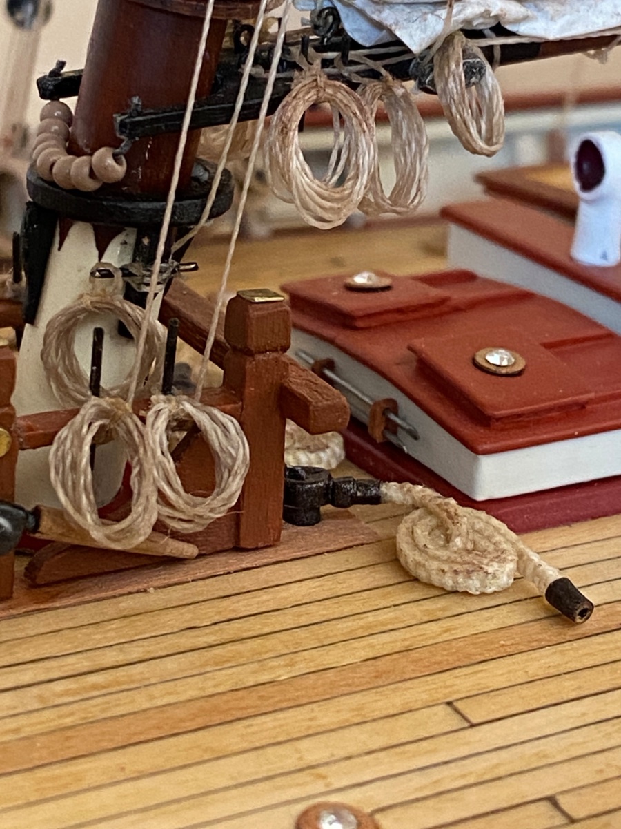
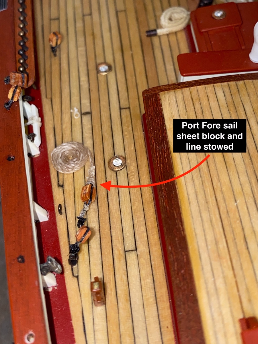
And finally the photo of the stowed line of Fore sail sheet line at port side

-
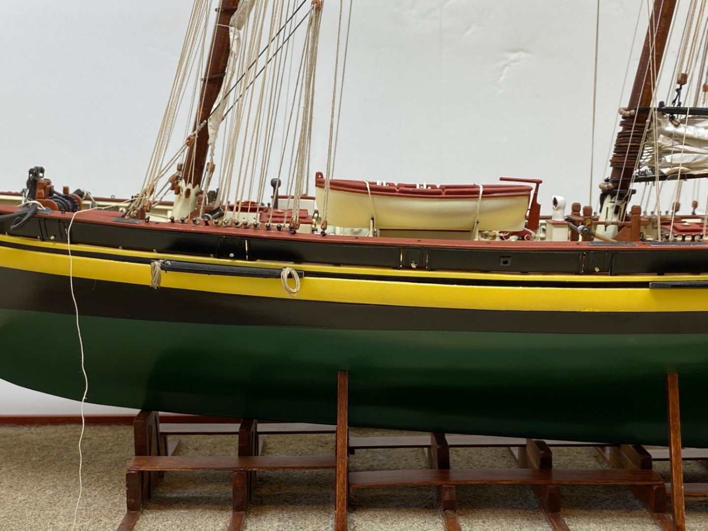
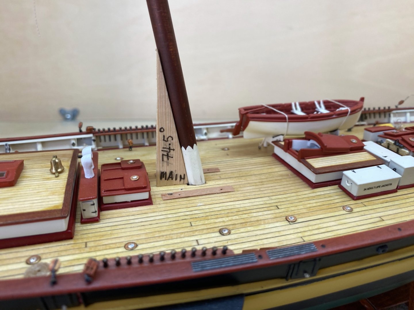
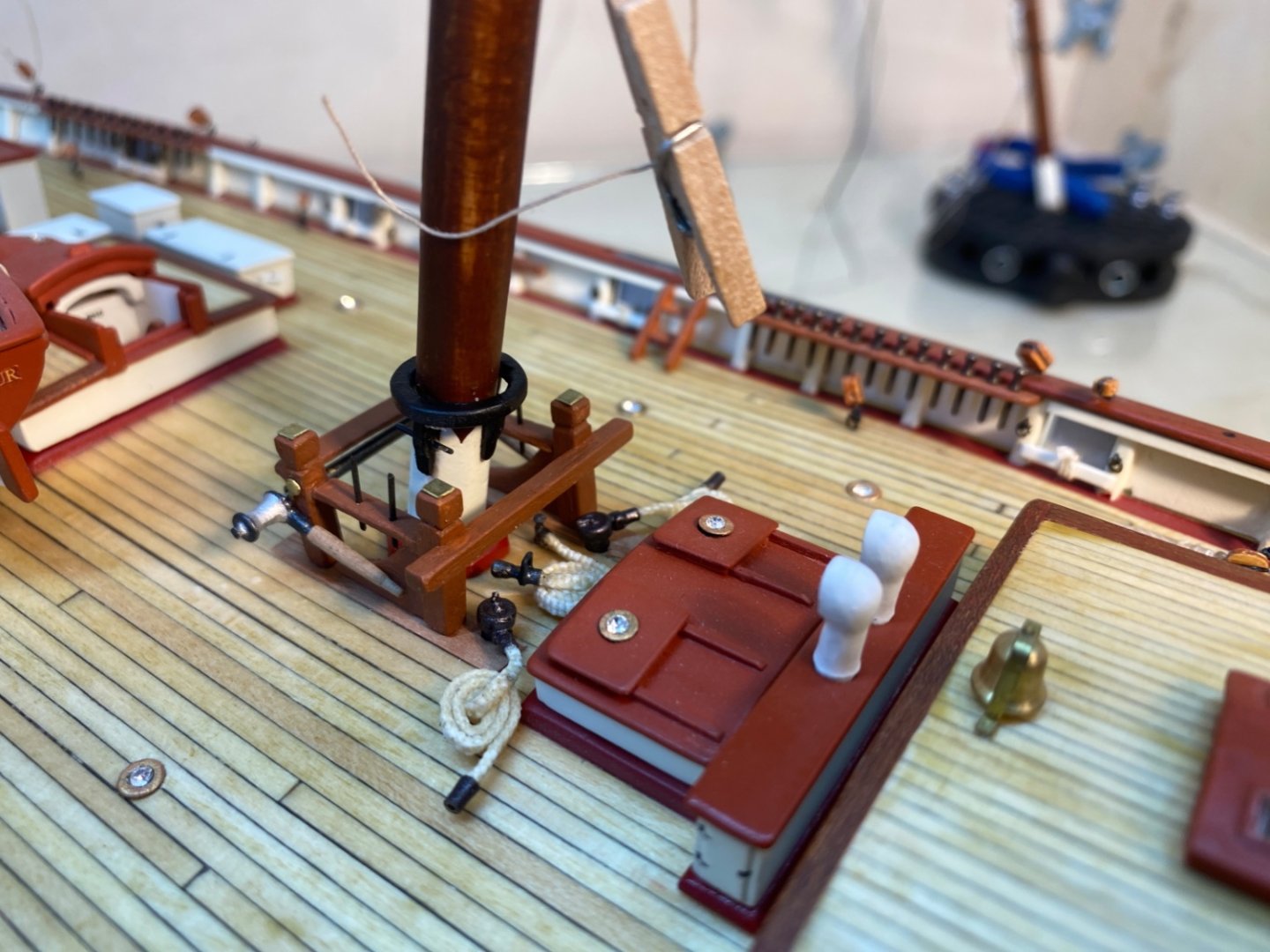
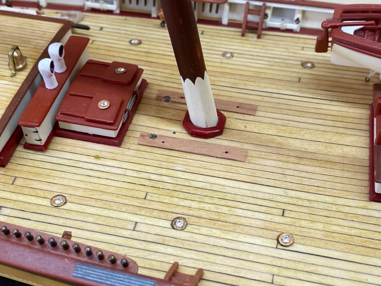
It was October 30th, 2022 and 26th month of the build.
It was now time to install the masts to deck.
Both masts have a rake angle with the deck. For the main mast the angle was 74.5 and for the fore mast 76.5 degrees. Two jigs were made from scrap wood to be used when installing the masts.
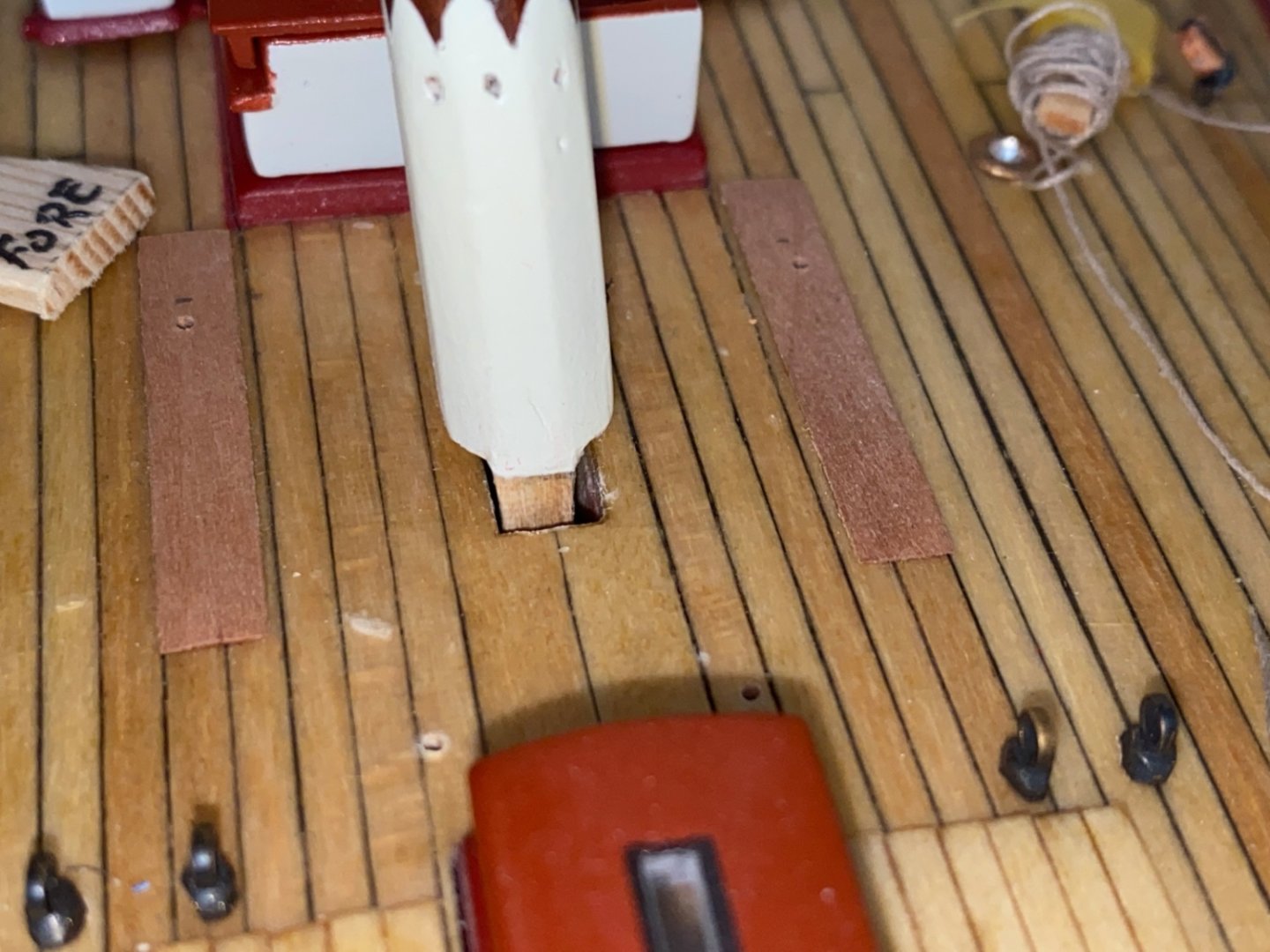
The slots for the insertion of the masts were a bit large for the mast tenons. Also the tenon of the fore mast was modified to maintain the fore-aft aligning of the mast.
I started the installation with the main mast. The plan was to add very thin wood pieces to the sides of the slot, insert the mast, align the rake angle using the jig and apply liquid gap filling CA glue with applicator to the sides of the slot.
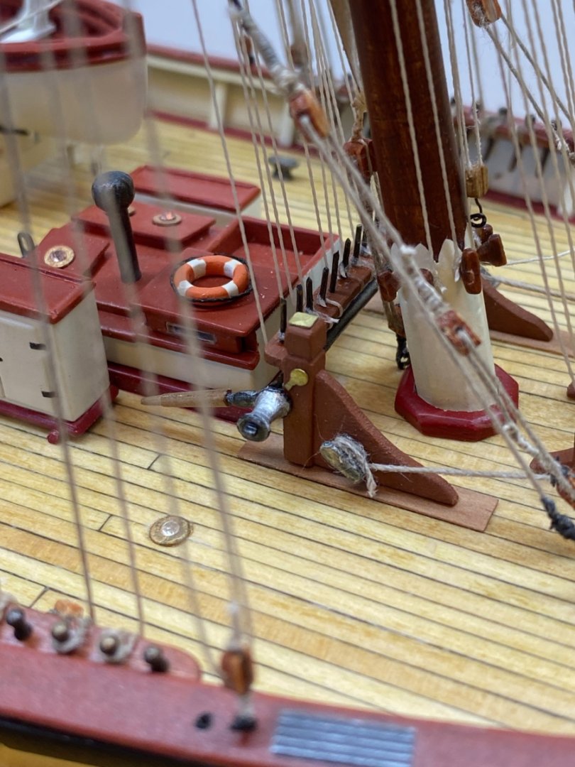
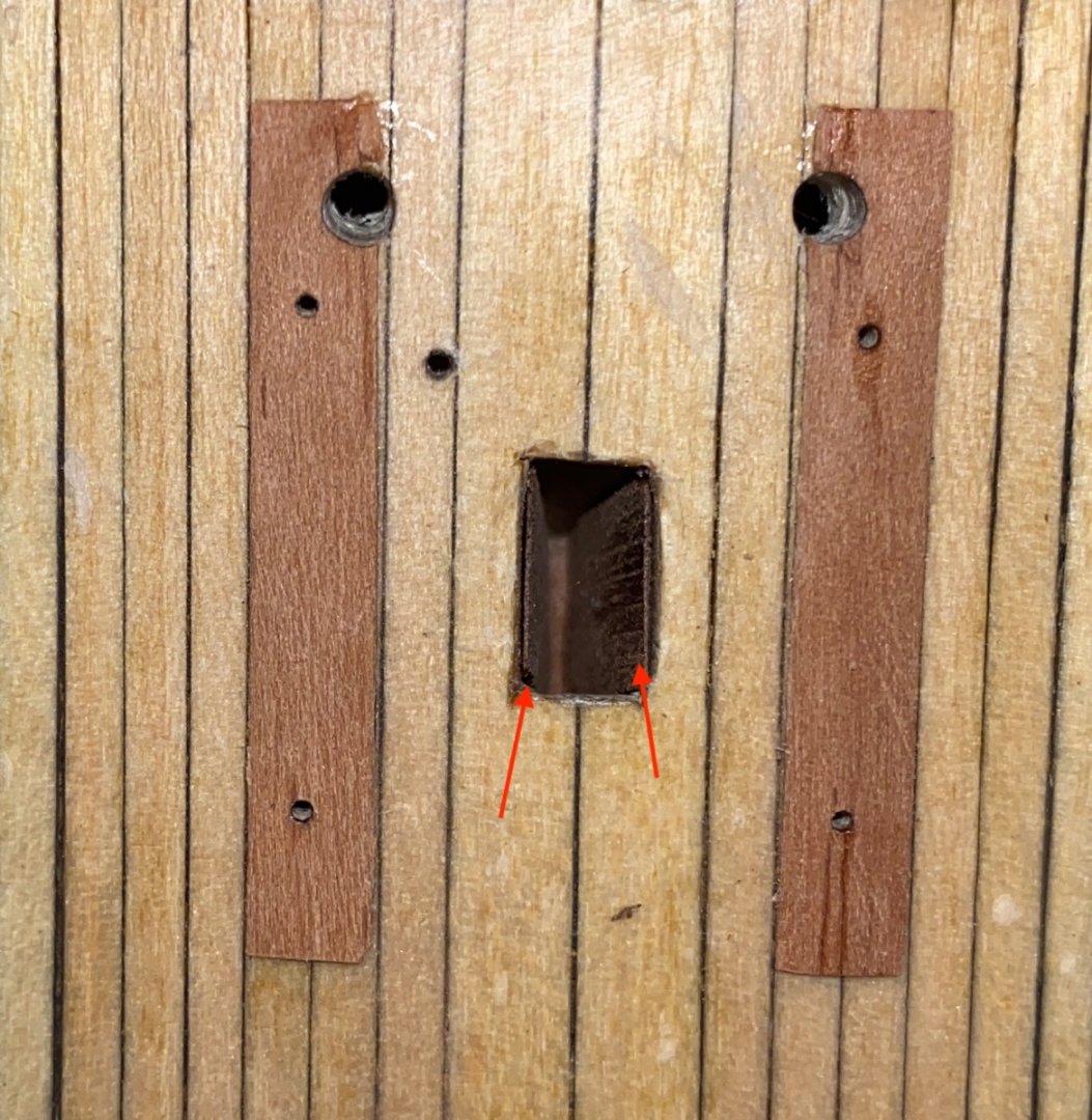
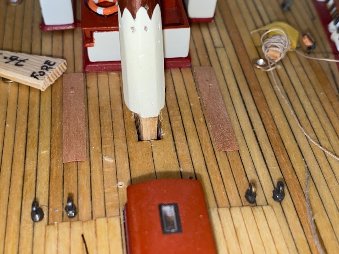
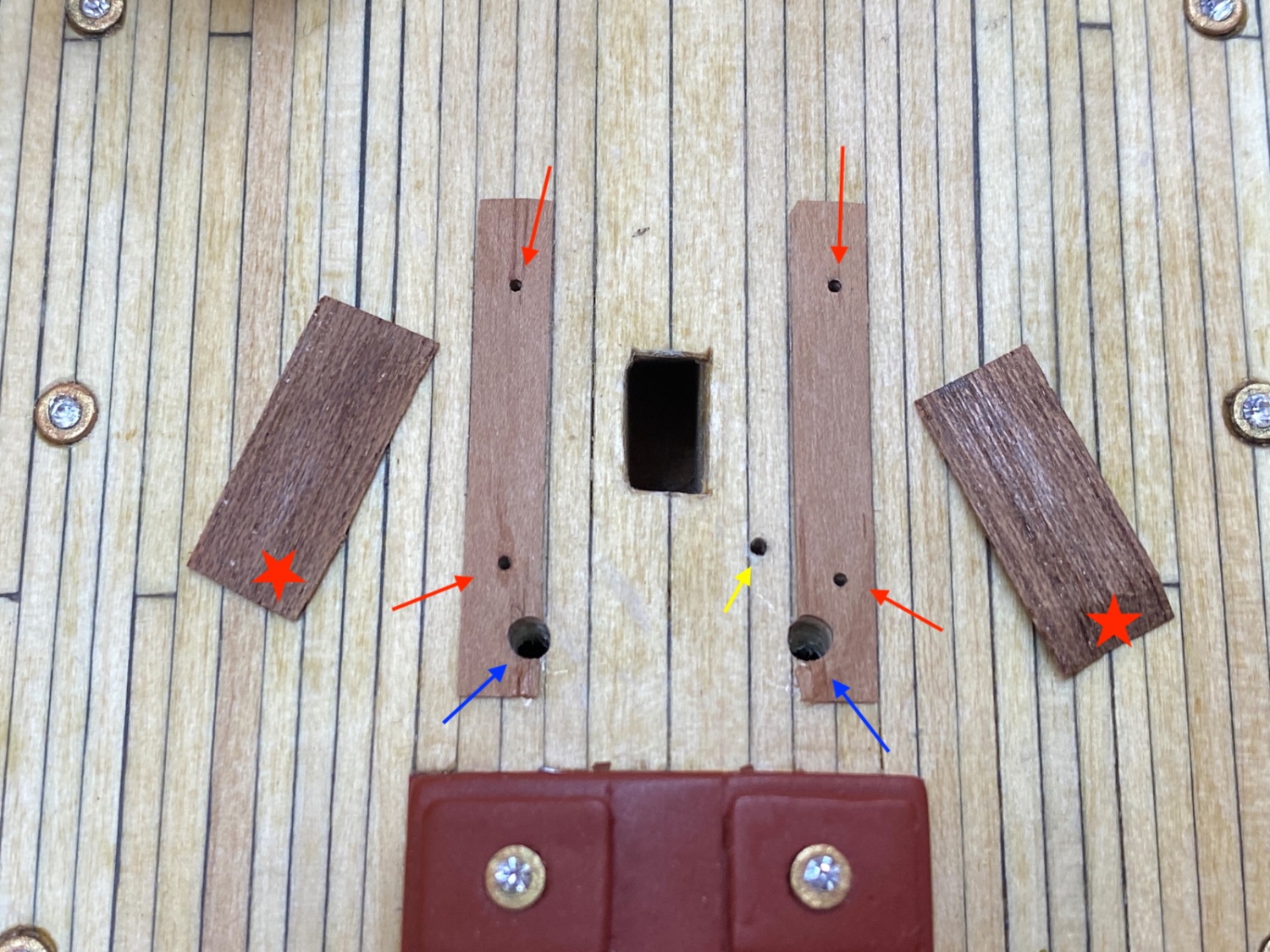
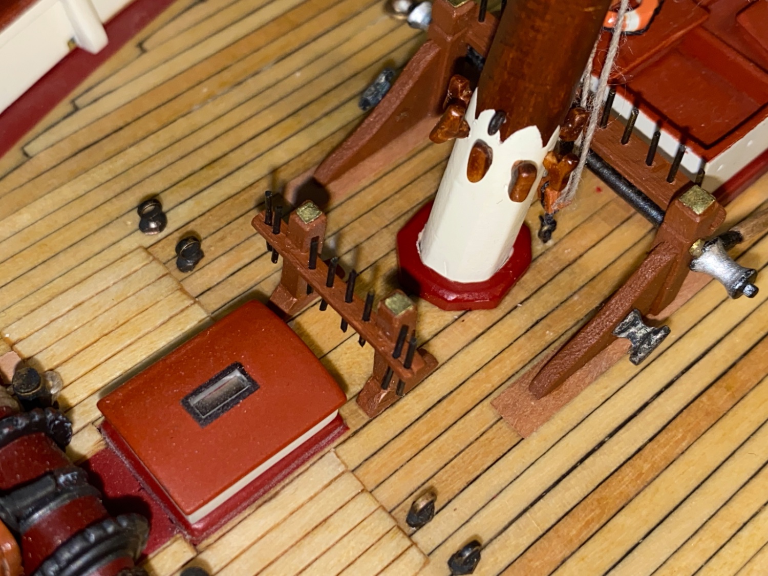
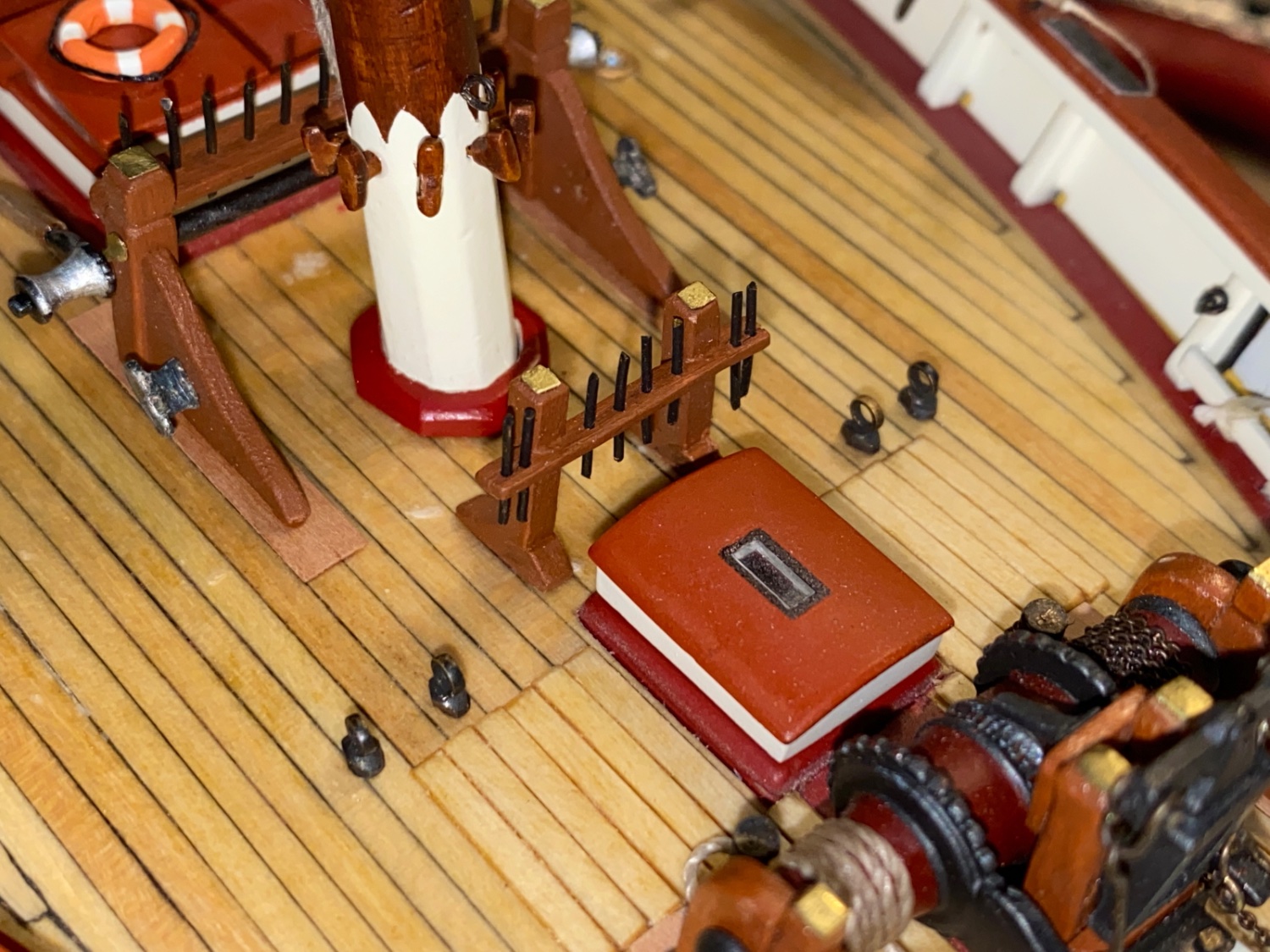
Here is a photo of the main mast insertion slot area. Holes for fife rail installation are red arrows, bilge pumps blue arrows and fire hydrant yellow arrow. Red stars are mahogany 0.4 mm veneer strips.

The mahogany strips (Red arrow) in position.
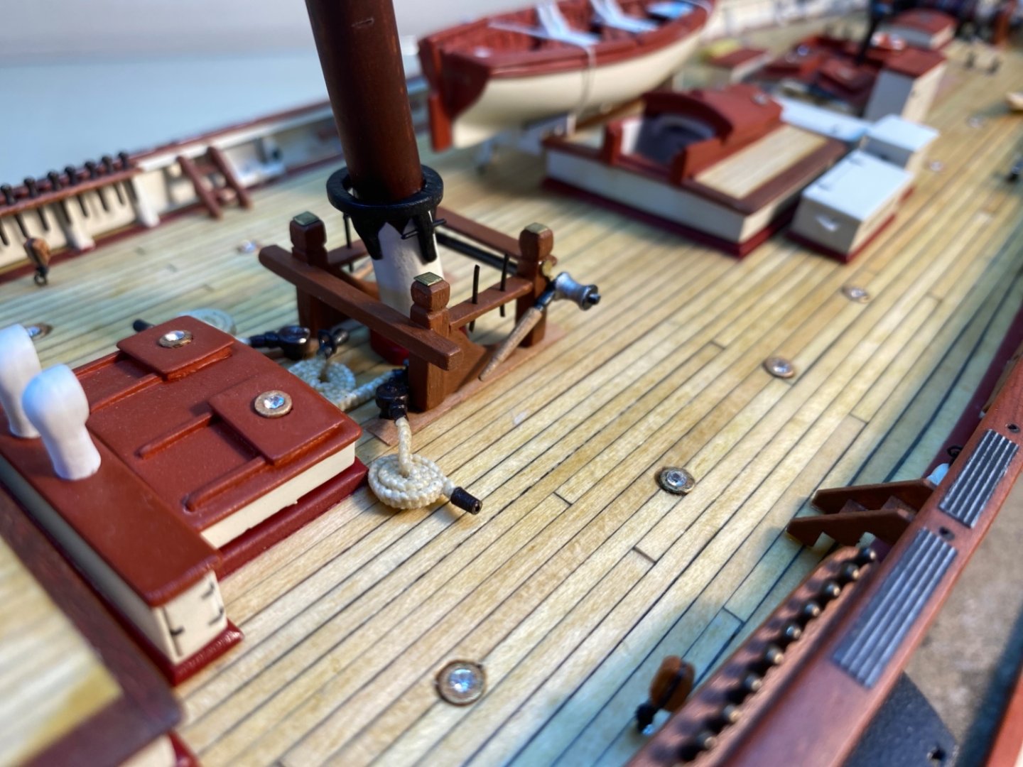
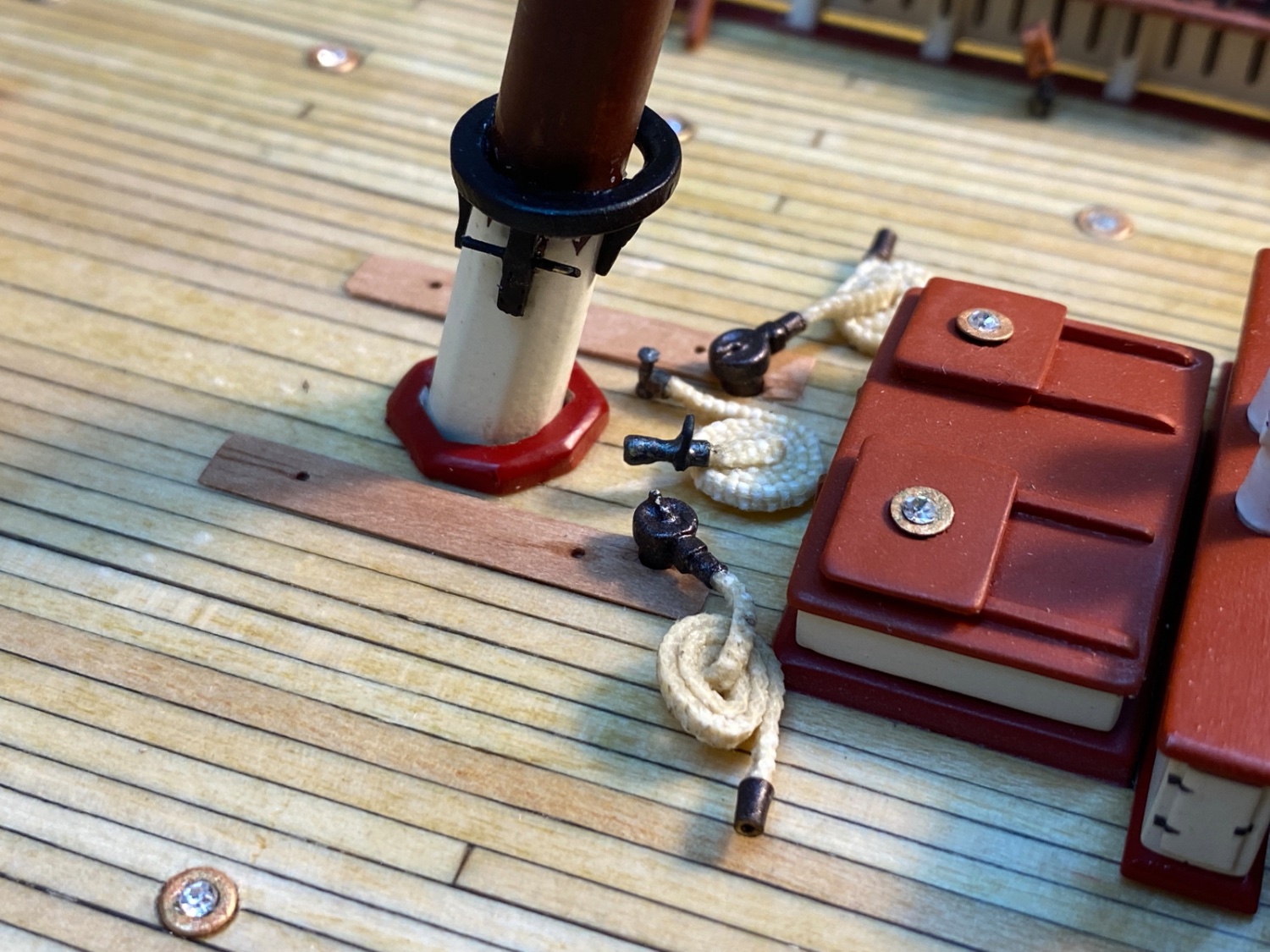
Plan proved to be true and after the insertion of the mast the rake angle was set by using the jig. Please note that the furled main sail was in a high temporary position and the mast wedge and the boom rest were already installed to the mast. Inserted mast was fitted to the slot tightly and applying CA glue was almost unnecessary.

Square position of the mast was checked fore-aft and aft-fore angles.

Mast wedge was placed and glued.

Boom rest with chocks were placed and glued.
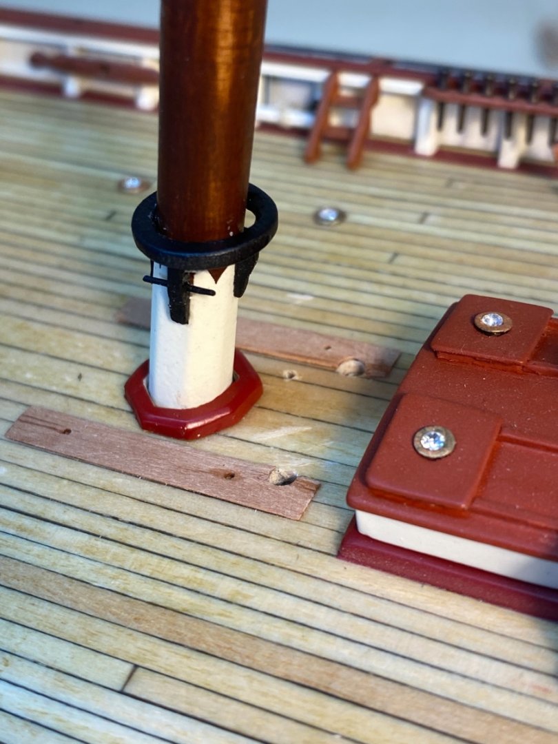
Bilge pumps and fire hydrant were also fitted to the their holes tightly and no CA glue was used.
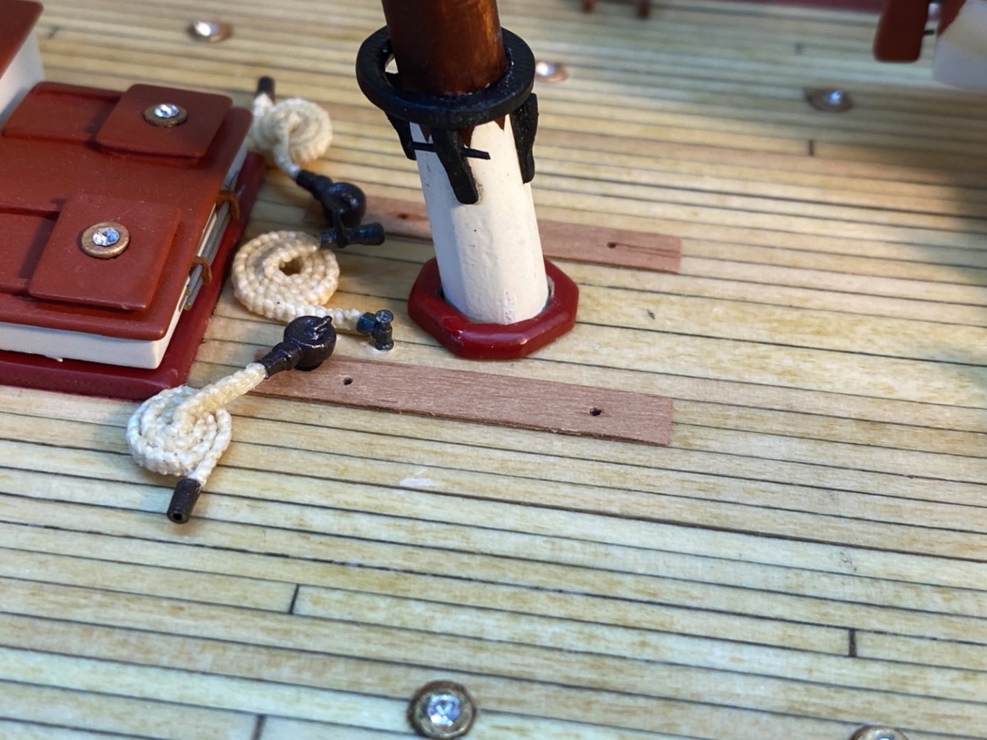
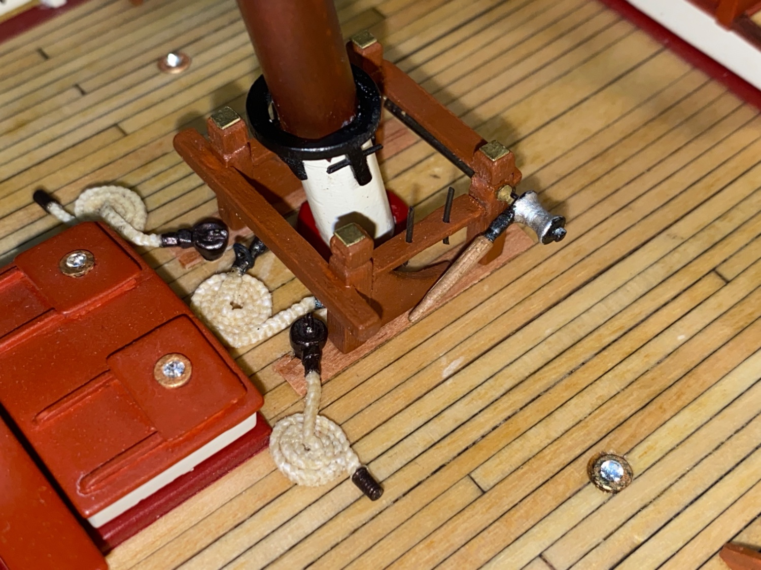
Different views of the base of the main mast at this step.

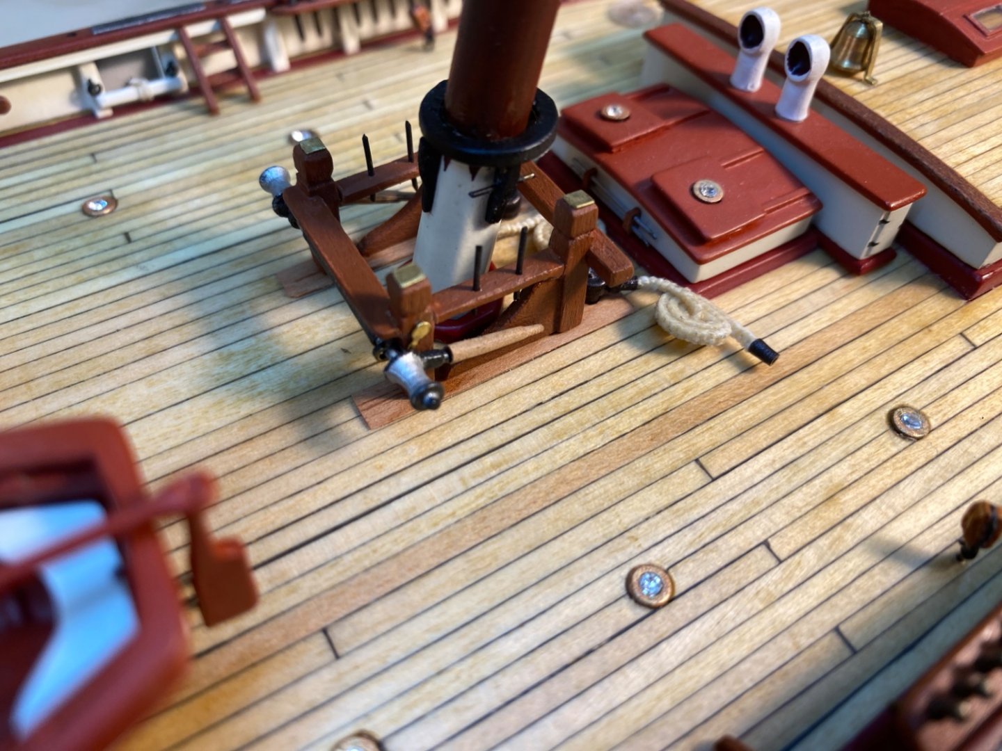
The next step was the installation of the fife rails. And it came with a million dollar question. How ?
Answer was simple. I disengaged the front part of the fife rails ( the part with the winch system), installed the aft part followed by the front part. The front and aft part connection points were later fixed with touches of CA glue. Here are some photos at this step.

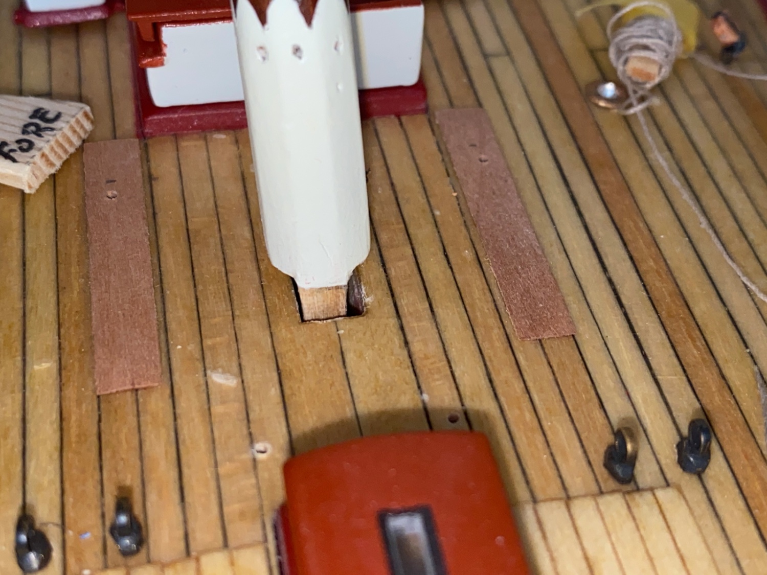
As I mentioned before the tenon of the fore mast was problematic and reshaped.The photo below shows the position of the mast had it not been modified and reshaped. There is a small tilt to starboard side.
The position of the mast after modification of the tenon. You can also see the 76.5 degree jig.
In order to fix the mast in the desired position , mahogany veneer pieces were added to aft-port (red arrow) and fore-starboard (blue arrow) areas of the slot.

After the mast wedge was installed , the fore mast was inserted to the slot. Surprisingly CA glue was also almost not needed and things went smoothly. After the rake angle was set Fore tack tackle was reeved to its block , just at the aft-port position of the fore mast base. Then the fife rail with the winch was installed.

Wood cleats and eyebolt were glued to the holes.


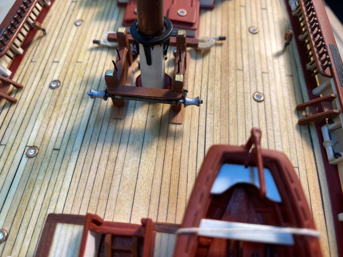
Finally the small fife rail in front of the fore mast was installed.

Main boom was lowered to its normal position.
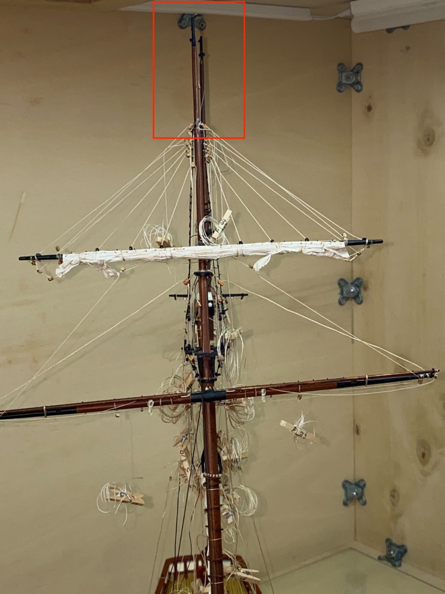
When the position of the masts were checked in the fore-aft axis there was a slight misalignment (Red rectangle) which was later corrected when rigging the running backstays.

As the mast installation step was done, the model now awaits the installation of fore sails. However I decided first to finish the rigging of cluster of lines , especially at fore mast, waiting to be belayed at the pin rails at the bases of the masts.
- ccoyle, Prowler901 and yvesvidal
-
2
-
1
-
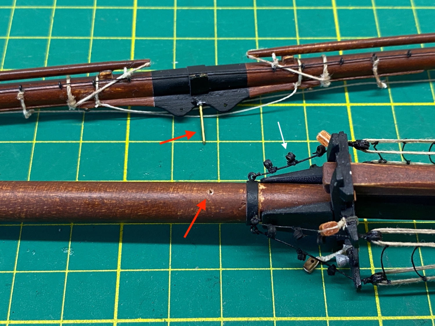
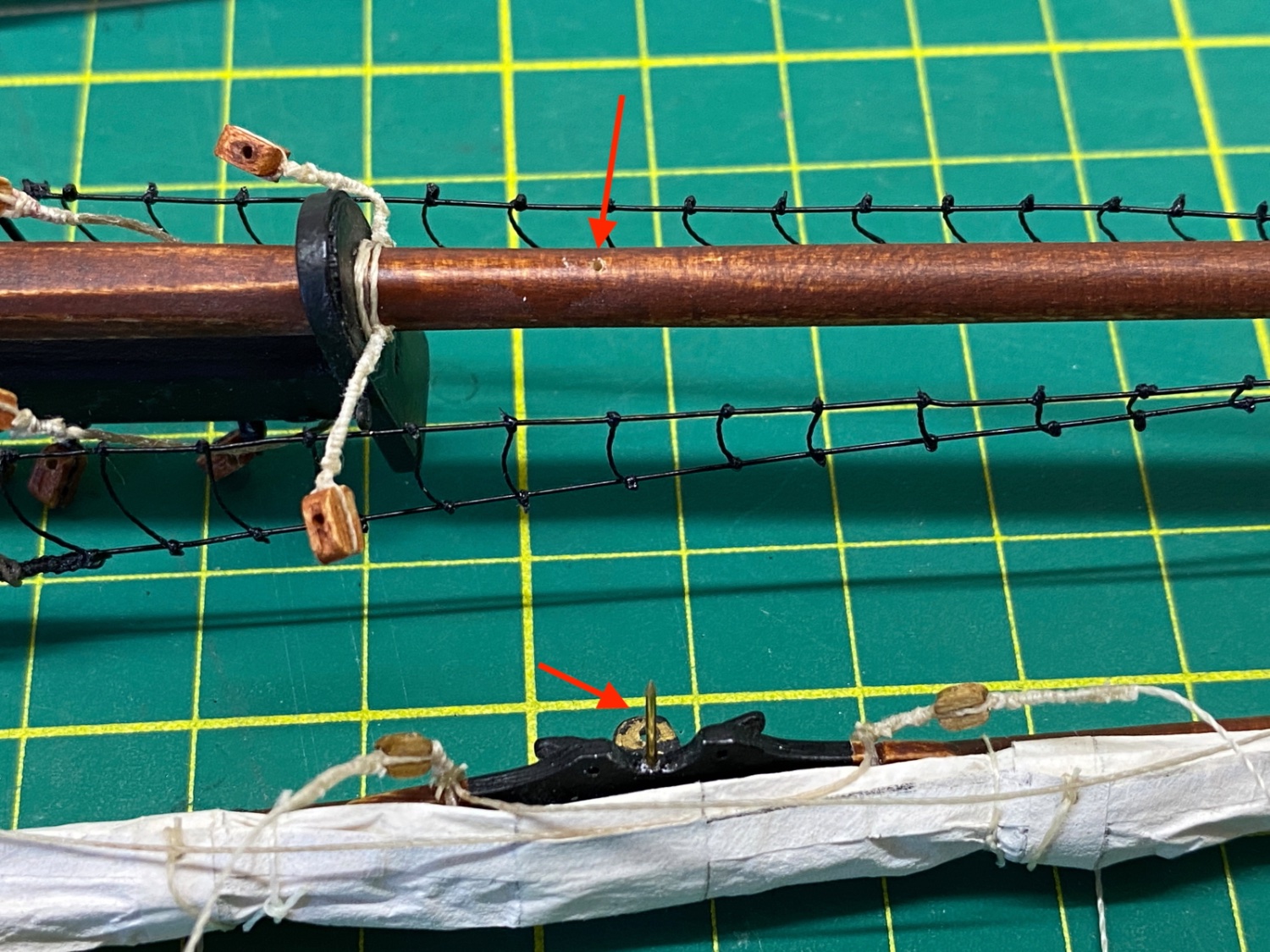
It was time to install the yards to fore mast.
In order to support the connection of the yards to mast, a pin was inserted to the center point of yoke and a hole was drilled on the mast where the yard will be glued to (Both red arrows).
Fore lower yard
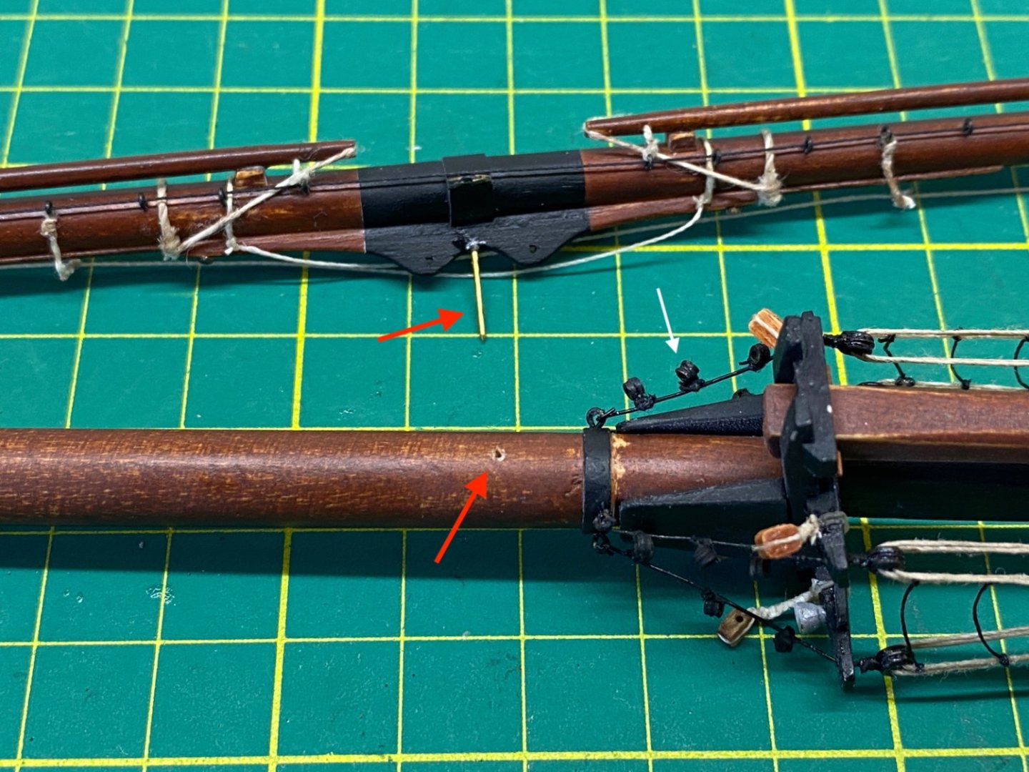
Fore Topsail Yard

The yards were dry fitted. Metal bands (Red arrow) at the top sides of the yard at middle must be paralel to the mast.
Fore Topsail Yard dry fitting. The position of the Topsail Yard must be at a lower level as the sail was furled.
Fore Lower Yard

Before the installation the rigging of the yards were checked and all the possible rigging was completed before the yards were installed.


I started with the Fore Lower Yard. The mast and yard were laid on a cutting mat and a square connection was achieved.
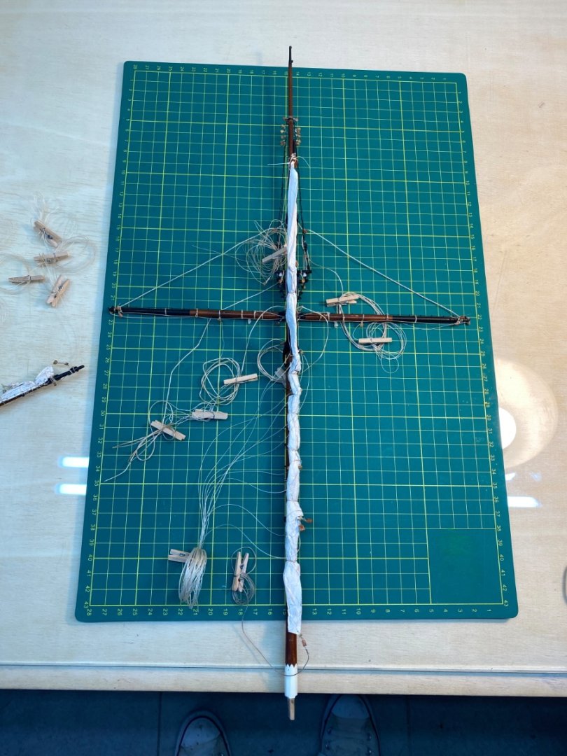
Then the Topsail Yard was installed in the same setup.
After the yards were installed all the possible rigging job was completed, this time before the installation of the masts to deck.
Here you see an example. There is a small wood piece with four holes attached to the fore side of the fore aft crosstree as you see in the photo from the plan. This piece acts as a fairlead to buntlines, leech line and reef tackle both p/s.
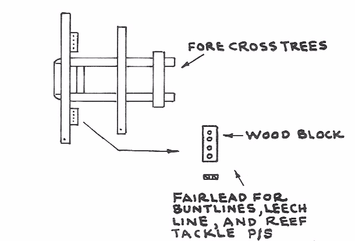
In the photo below you see that area in the red rectangle .
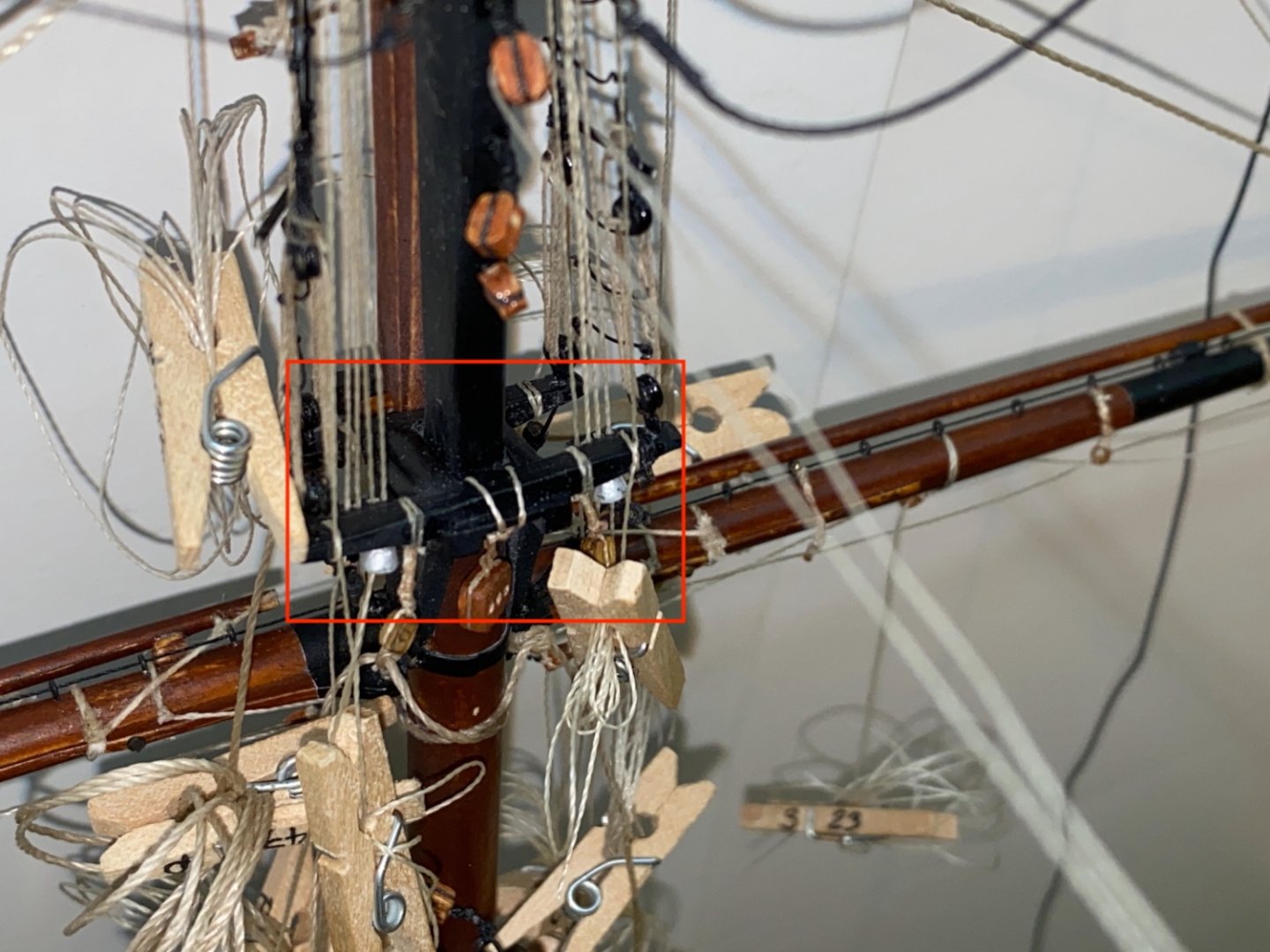
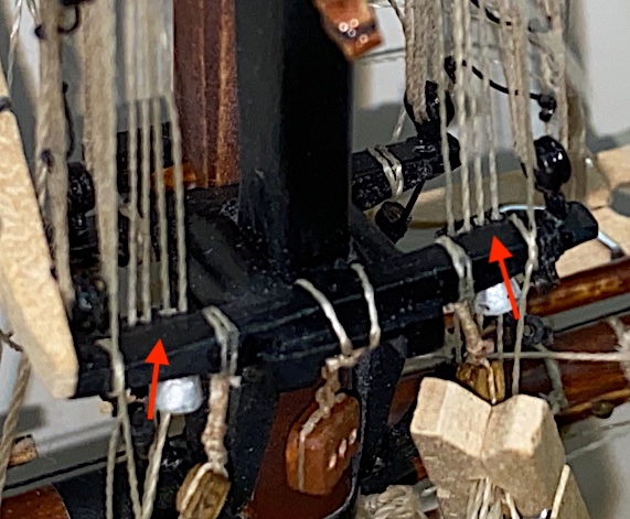
Close up photo shows the four lines (Red arrows) at each side. To reeve these lines after the mast/yard was installed to deck would be very difficult.
The masts were ready to be installed to the deck.

-
-
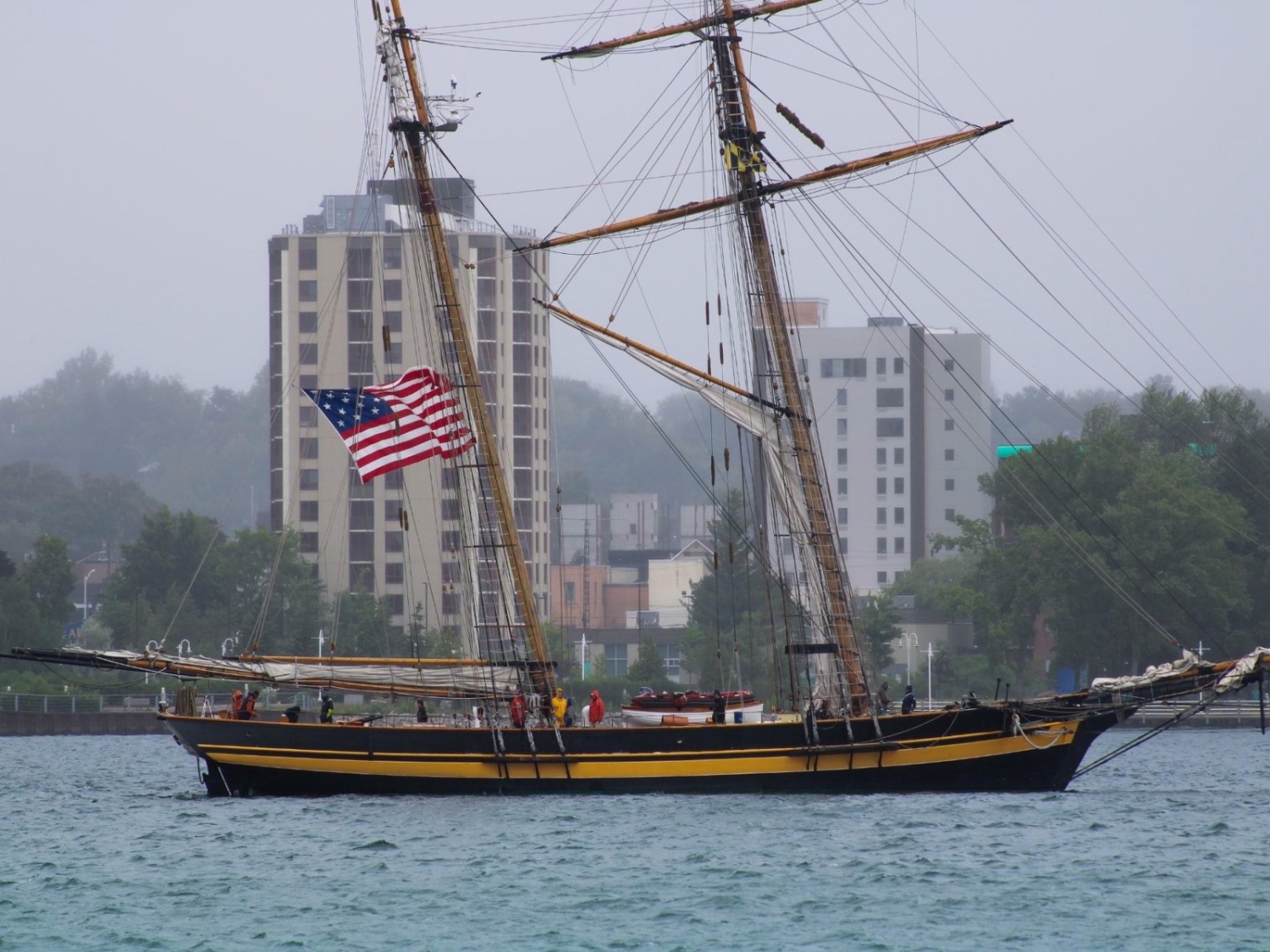
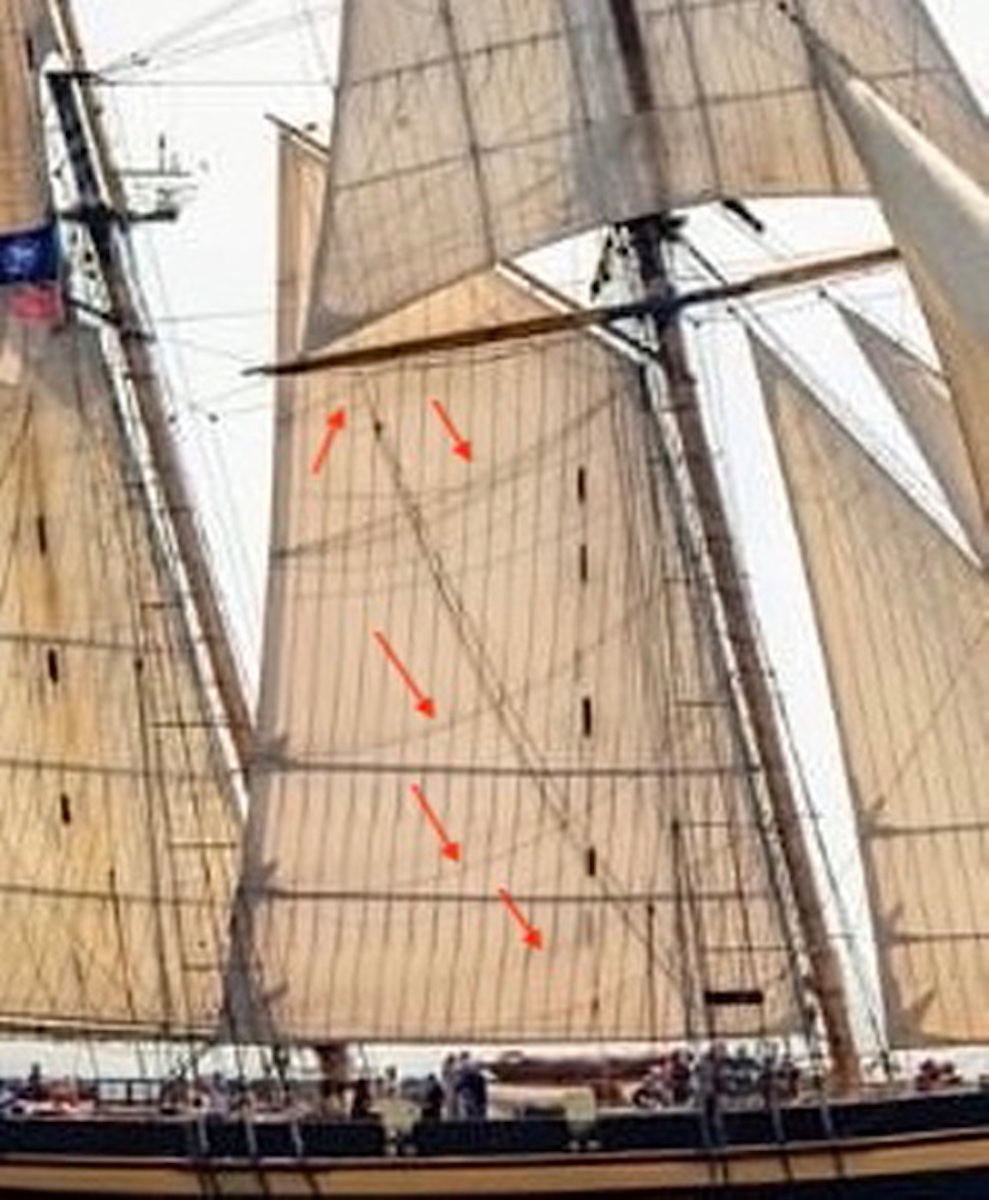
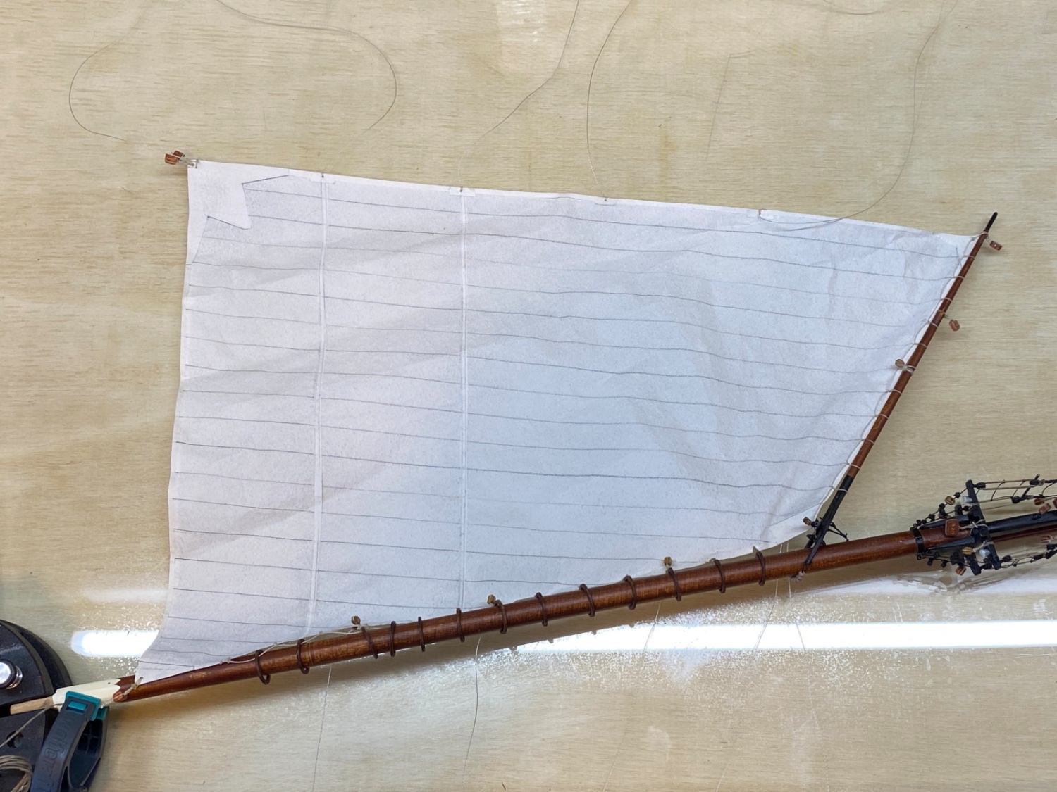
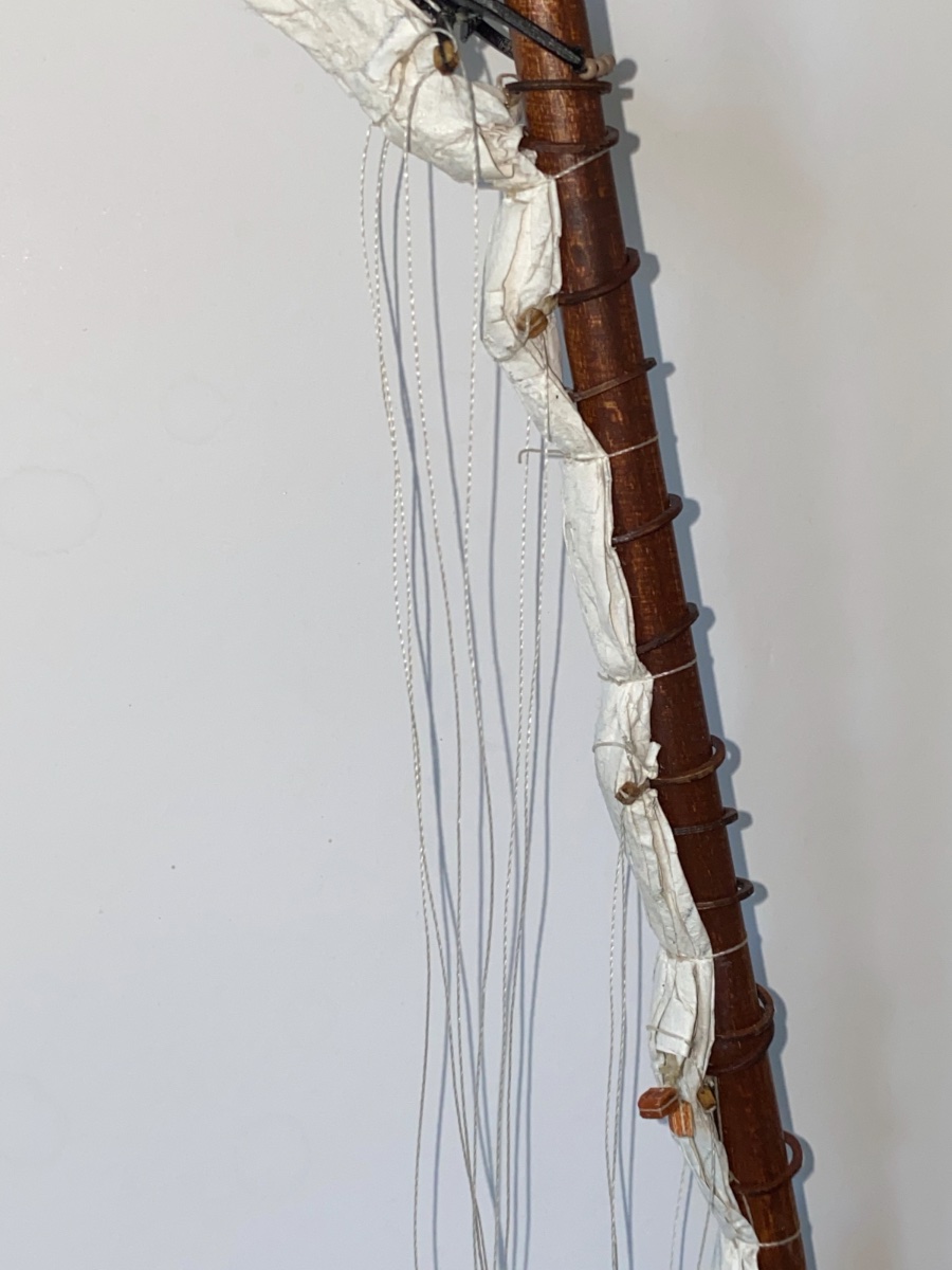
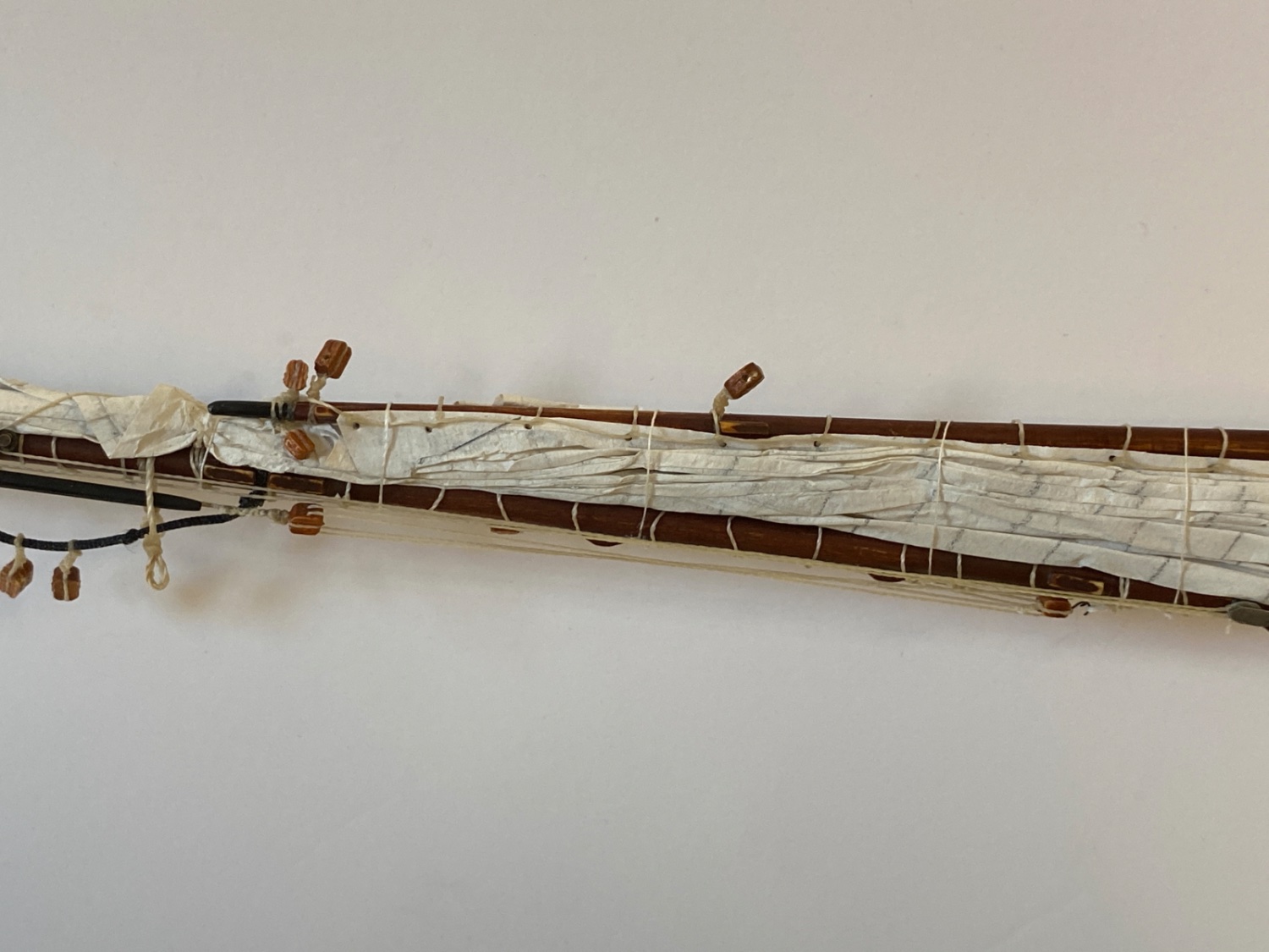
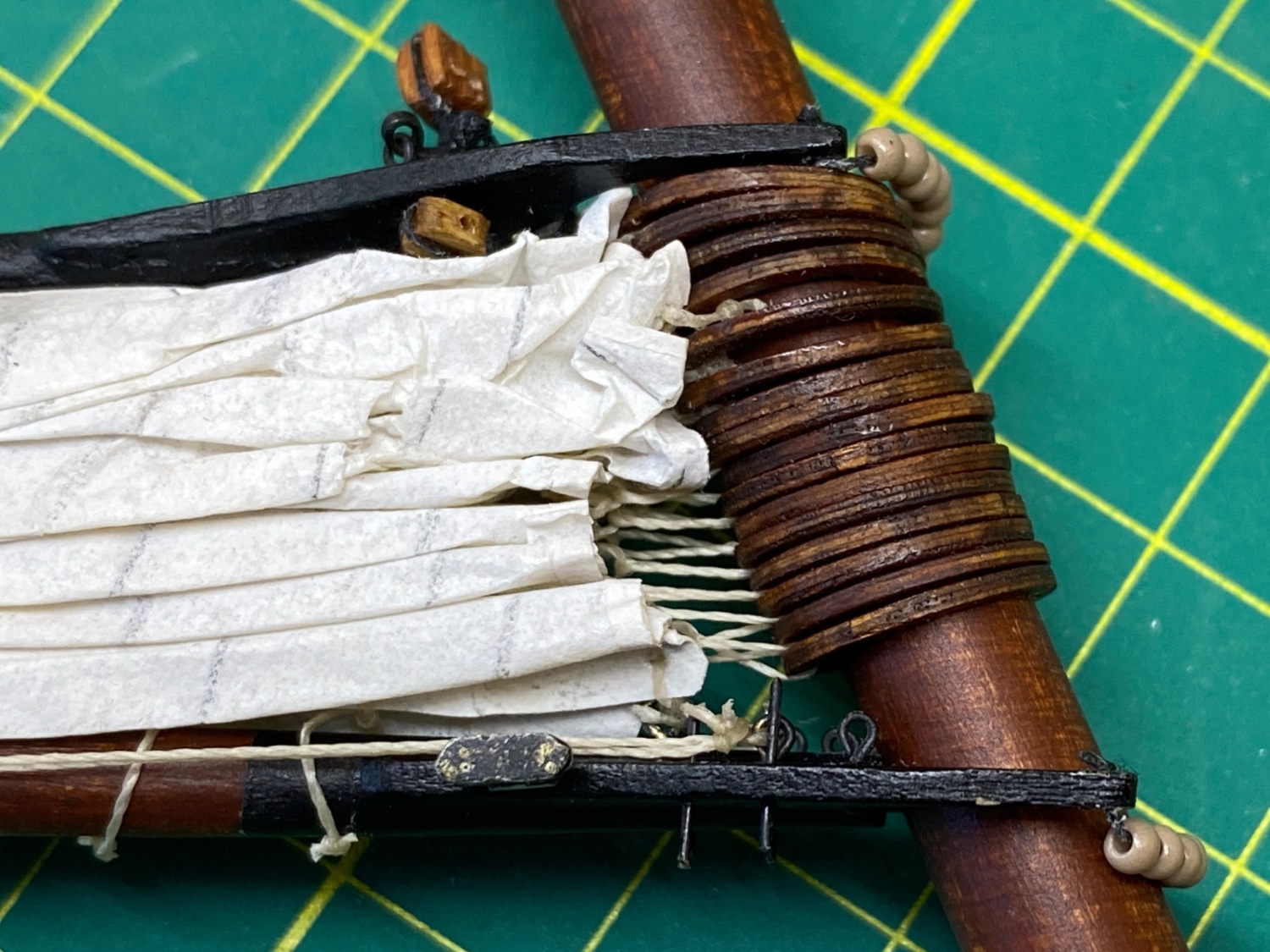
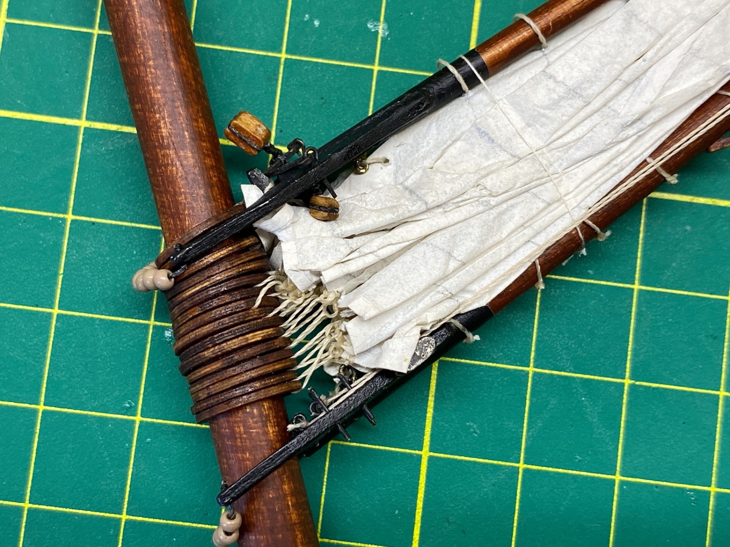
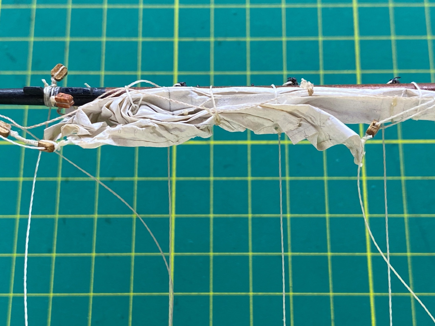
Fore Sail is furled to fore gaff and fore mast. The position of Fore Gaff changes. Some photos from real ship with fore sail furled.
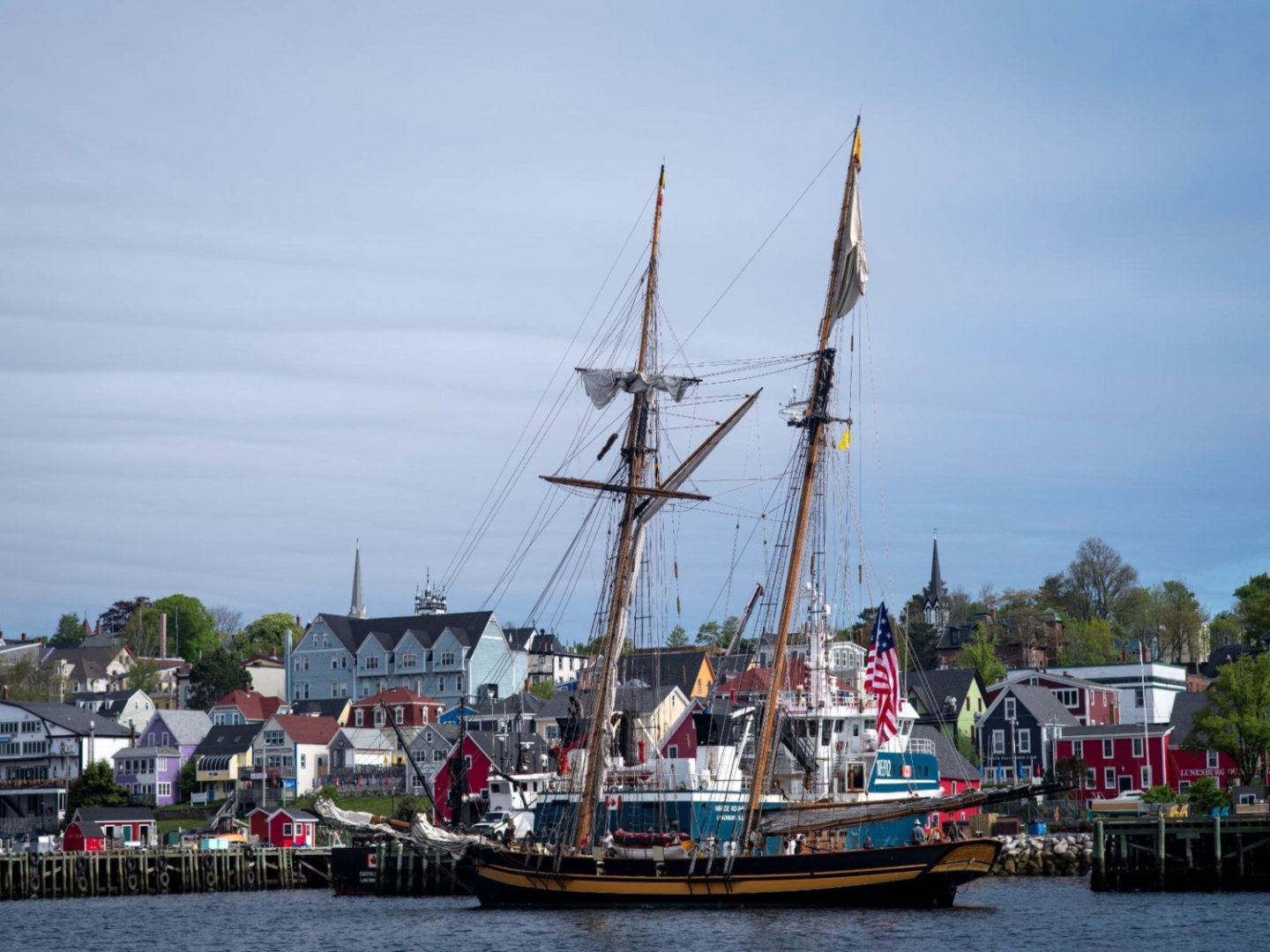
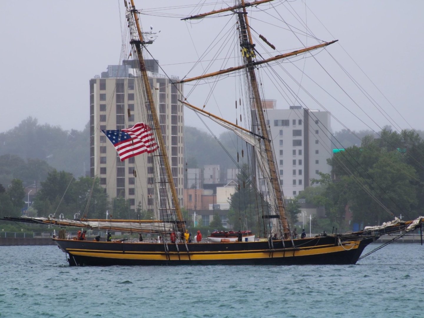
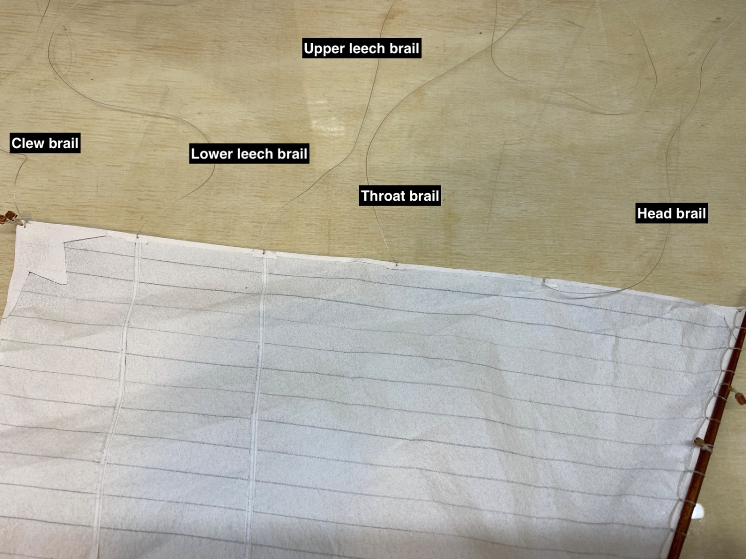
Fore sail is furled by the help of 5 brail lines p/s. They are head brail, throat brail, upper leech brail, lower leech brail and crew brail. There is also a sixth brail, foot brail, but it does not have primary effect on fore sail furling. In the photo of the real ship's fore sail the brail lines are indicated by red arrows.

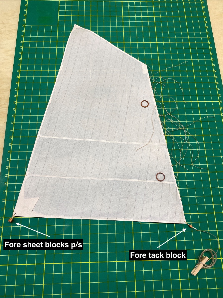
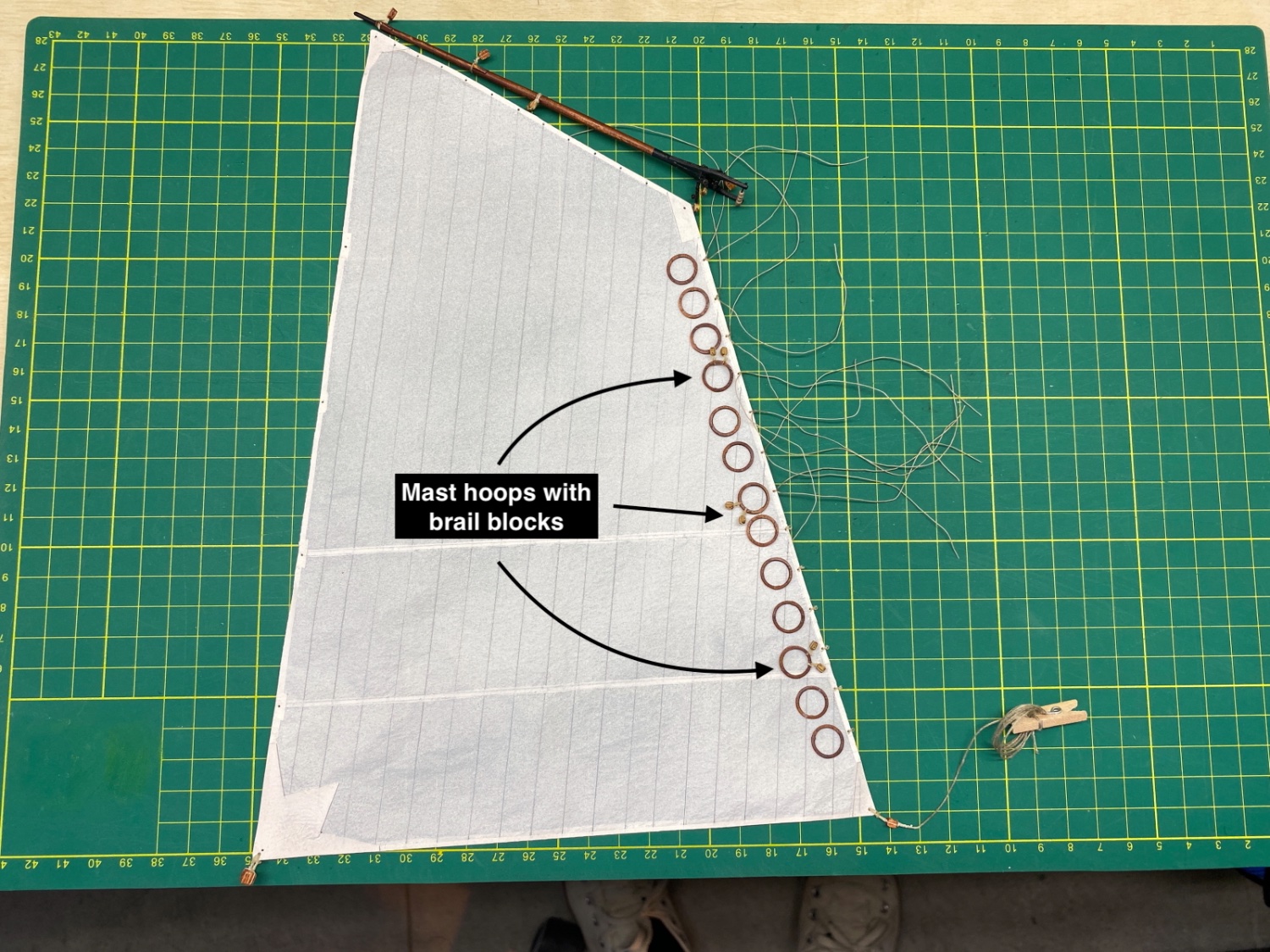
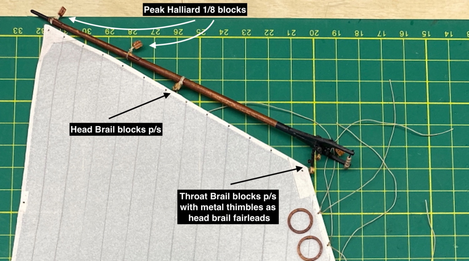
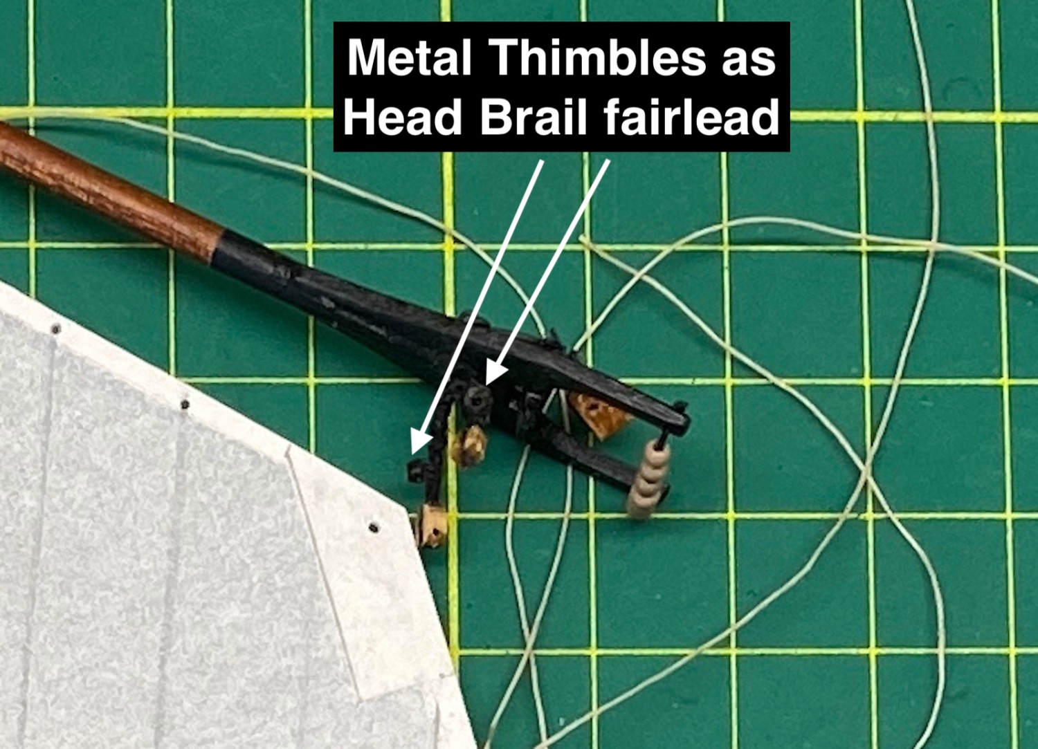
The sail was rigged like the main sail though there were some differences. Three of the mast hoops have brail blocks (p/s) for upper leech brail lines at top, lower leech brail lines at middle and clew brail lines at bottom. Fore gaff has two 1/8 peak halliard blocks like the main gaff. However it has two single blocks (p/s) at middle location for Head brail line and two single blocks under the jaws for throat brail line. The latter also have metal thimbles attached (p/s) as fairlead for head brail line. Mast hoops up to the upper reef band level are not seized to the sail just like the main sail hoops and a line passed through connects them to the sail. At aft clew there are two 1/8 double blocks for fore sheet and at fore clew there is one double pennant block for fore tack tackle. Here are some photos


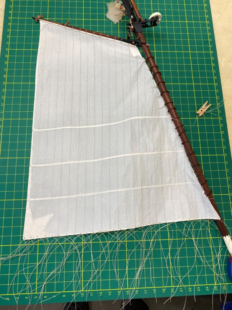
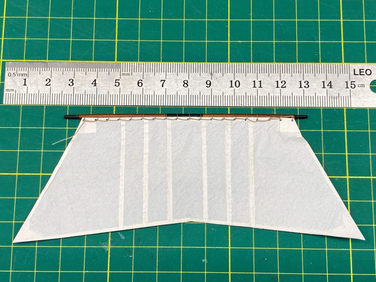
Fore sail was seized to fore gaff with continuous line like the Fore Topsail and Main sail. Mast hoops were also seized.
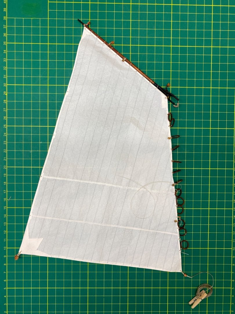


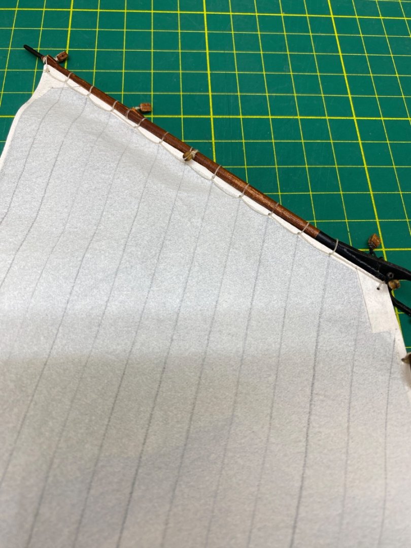
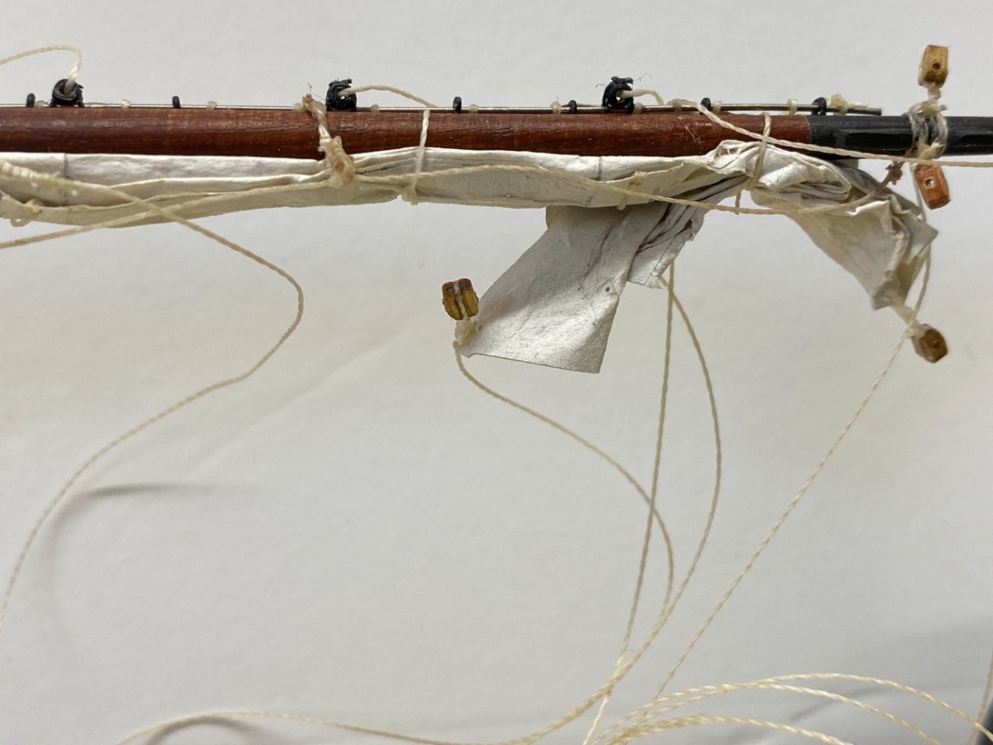
The sail was then installed to fore mast and laid on glass surface. At this step 2x5 brail lines (p/s) were seized to leech. Port side lines lay under the sail. Also at this step the position of the fore gaff was set.

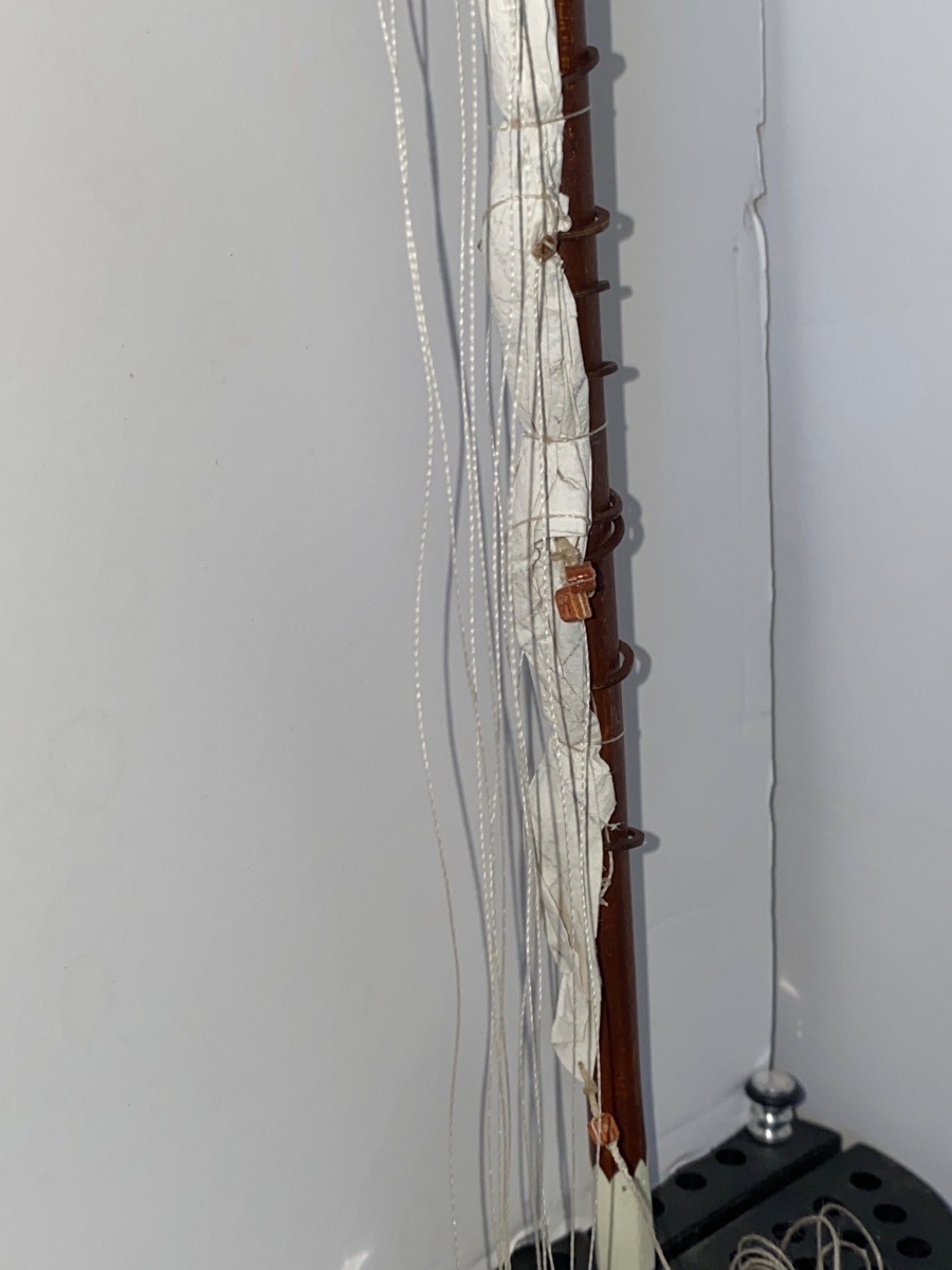
Starboard side brail lines
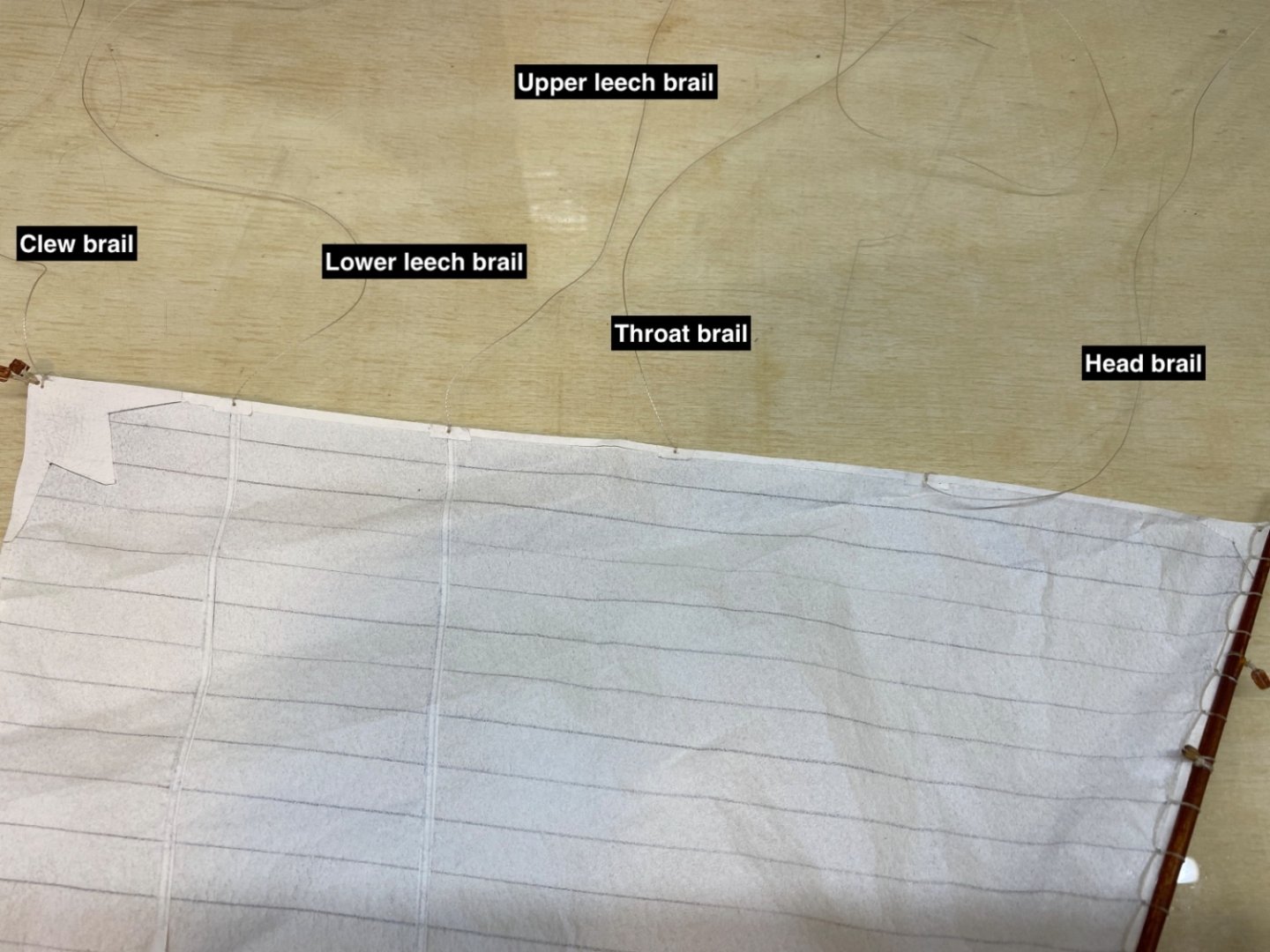
Port side brail lines. These are were reeved through their related port side blocks which can not be seen in the photo.
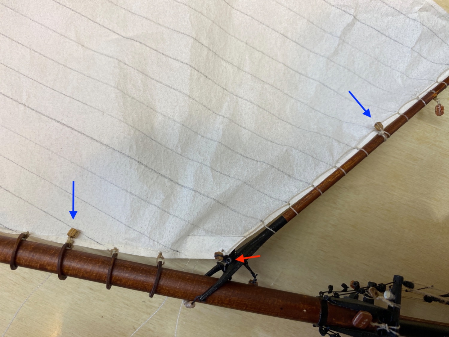
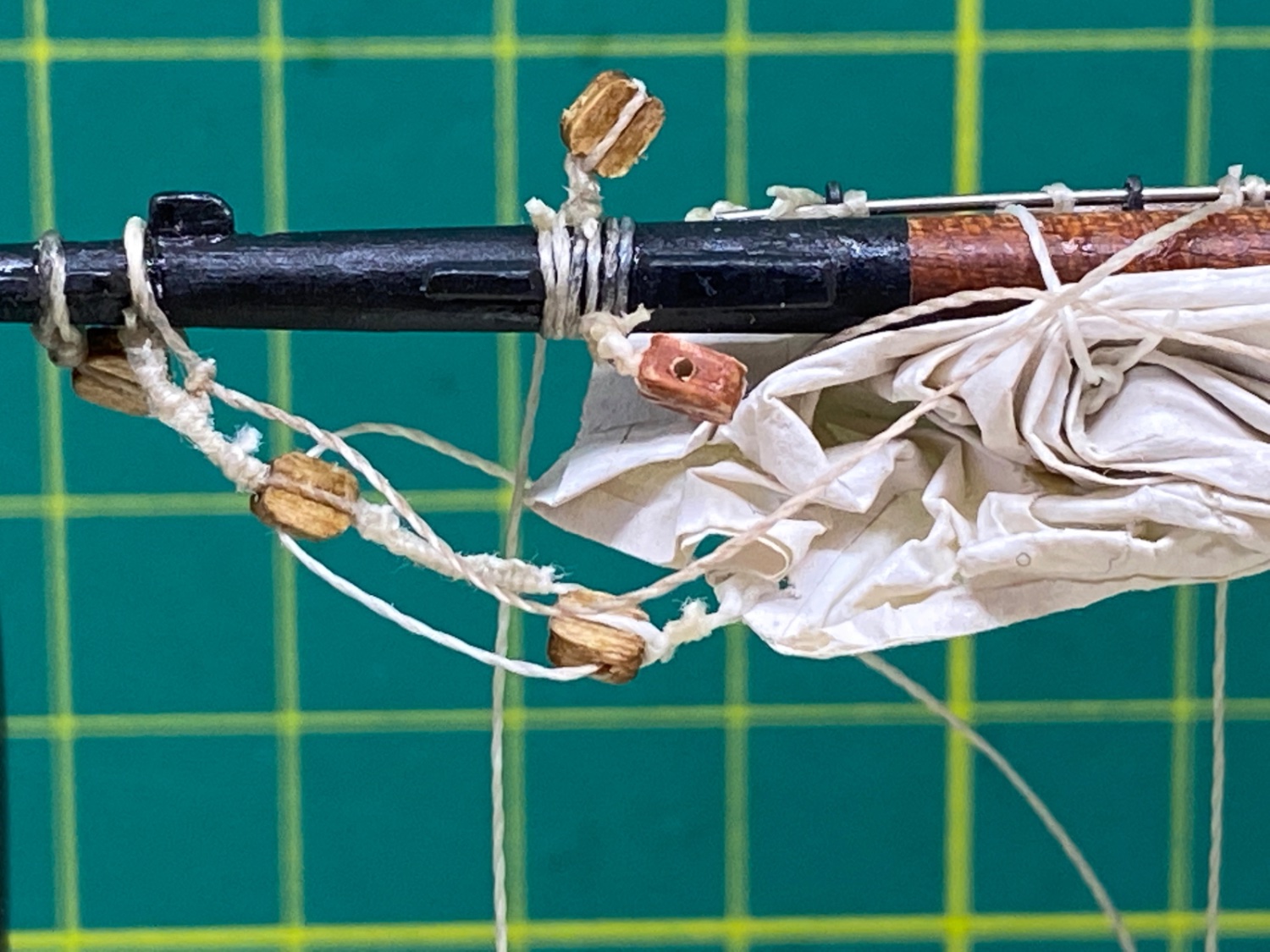
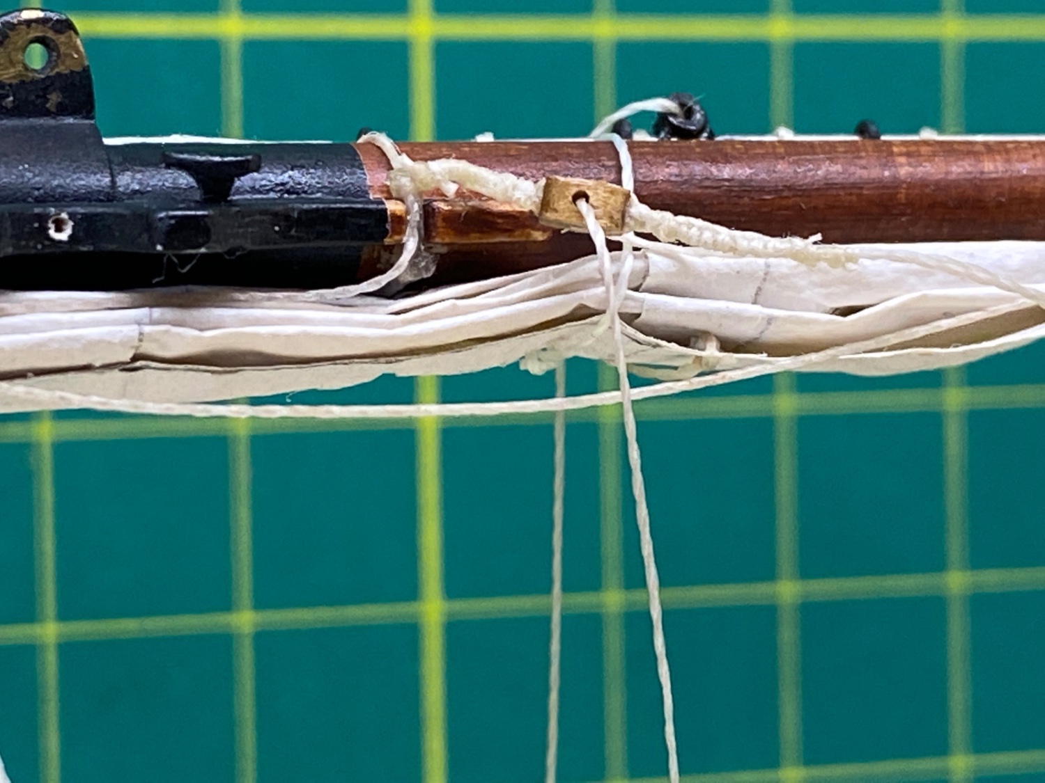
The position of the blocks must be controlled at this stage with reference to port and starboard ones exposed on the correct side. Blue arrows are blocks and red arrow is metal thimble on starboard side.

Sail and mast relation at the lower parts of the mast
Before starting to furl the sail, all the starboard side brail lines were also reeved through their related starboard side blocks. Head brail line was also reeved through the metal thimble seized to throat block after reeved through the block at the gaff.
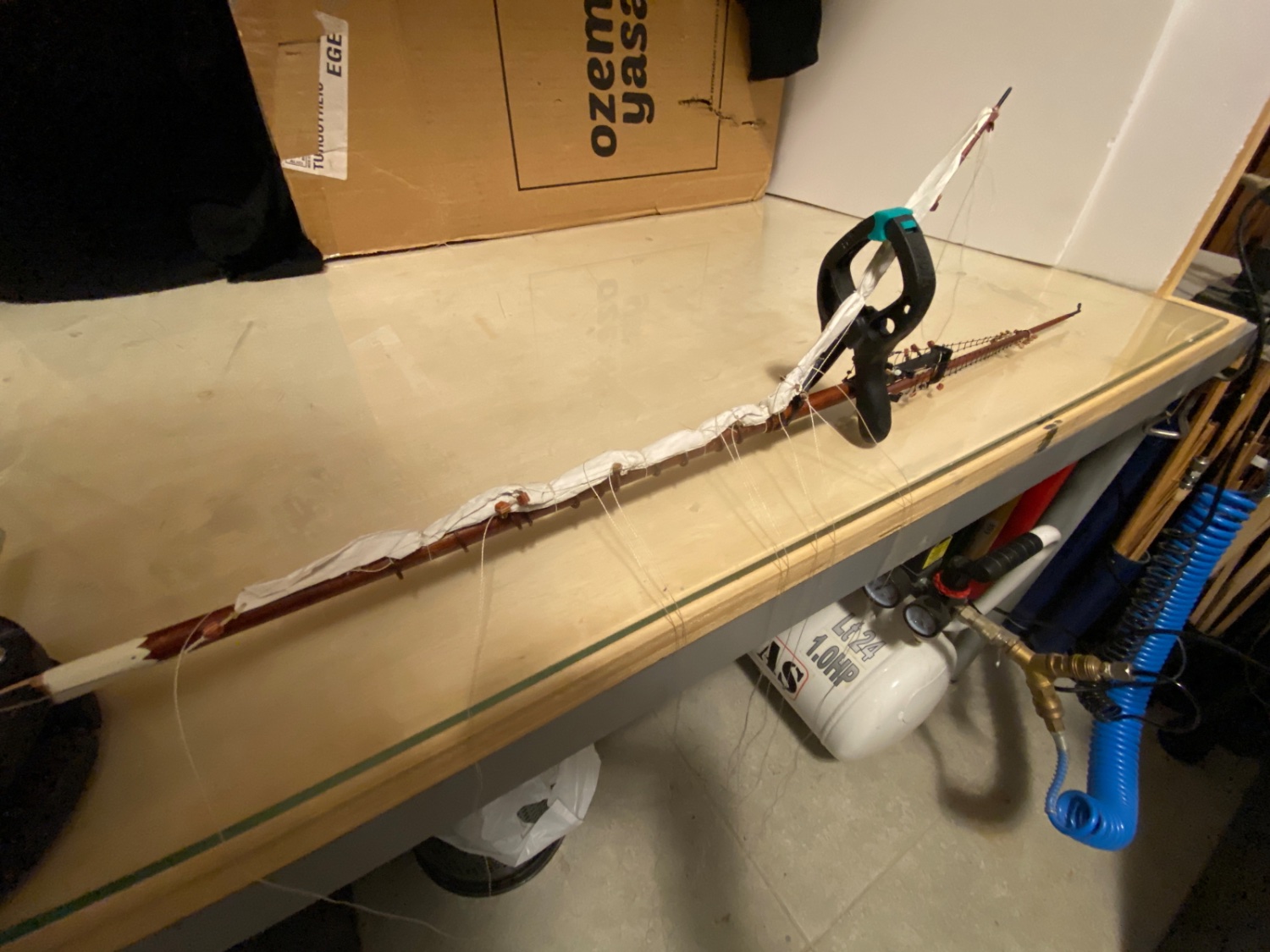
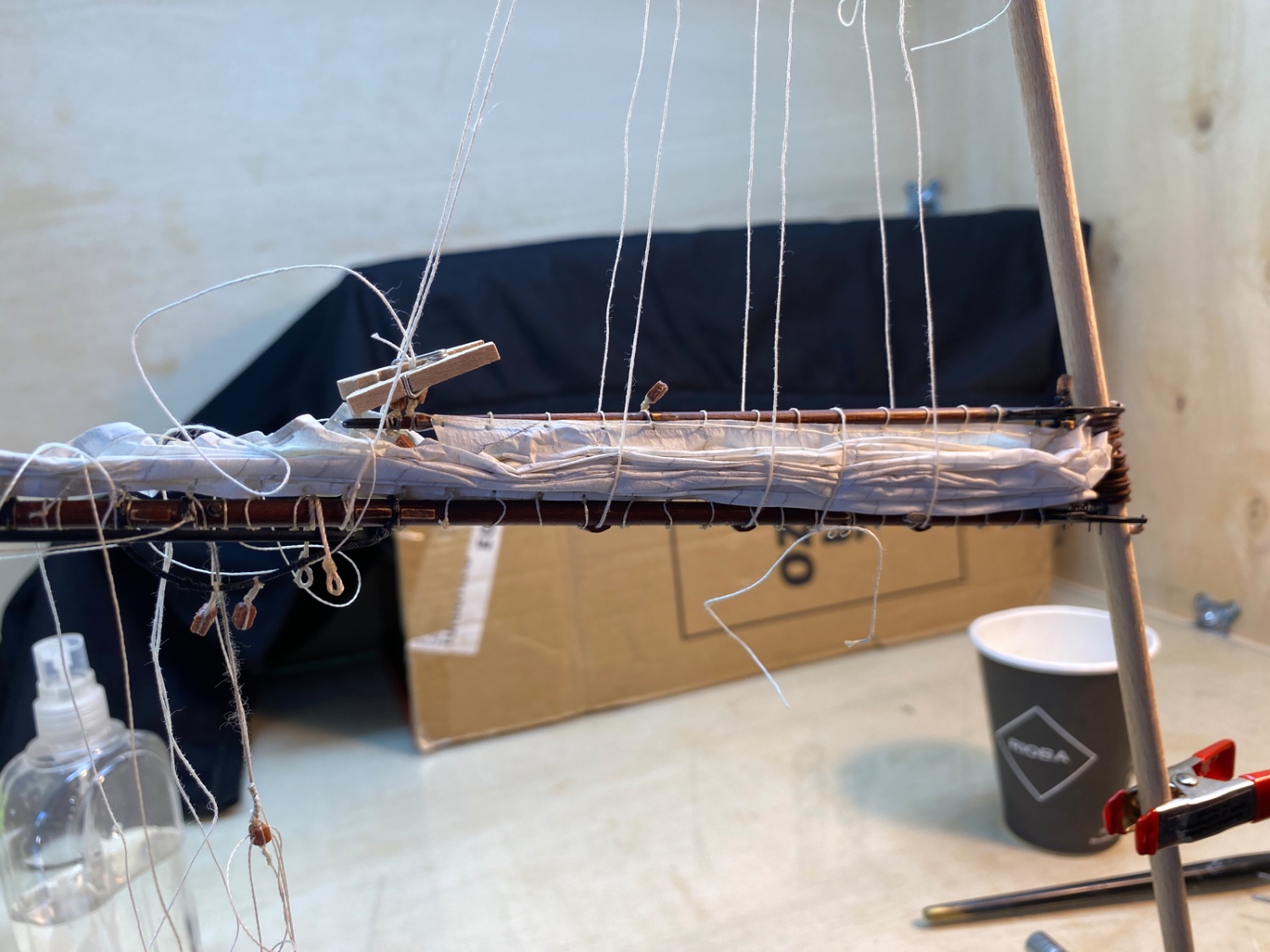
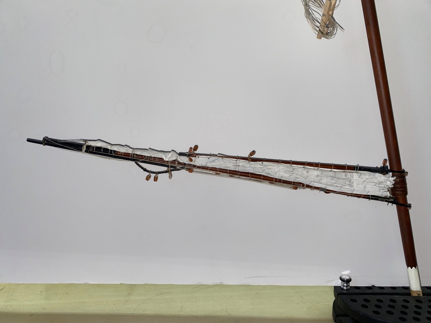
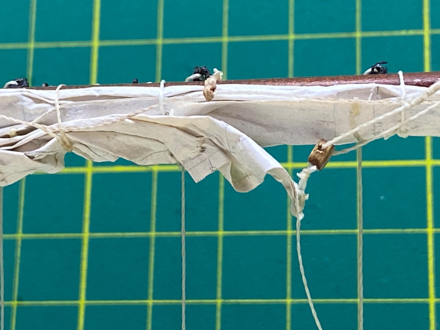
I started wetting the sail from the gaff and mast border areas and slowly and carefully created folds. Both starboard and port brail lines were retracted simultaneously until the desired furling was achieved. Here many reshaping was done. When the desired furling shape was achieved furled sail was fixed by 6 overhead knots and water diluted white glue was applied by a dry cut brush. In the real ship brail lines were used for this purpose.
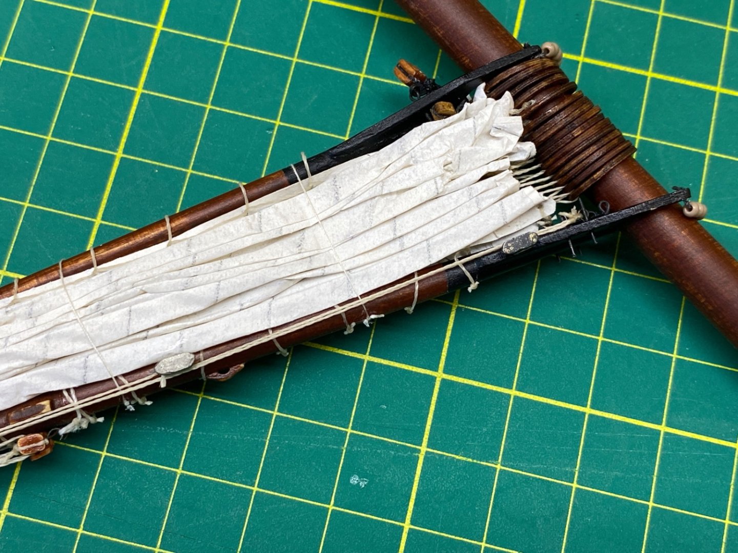
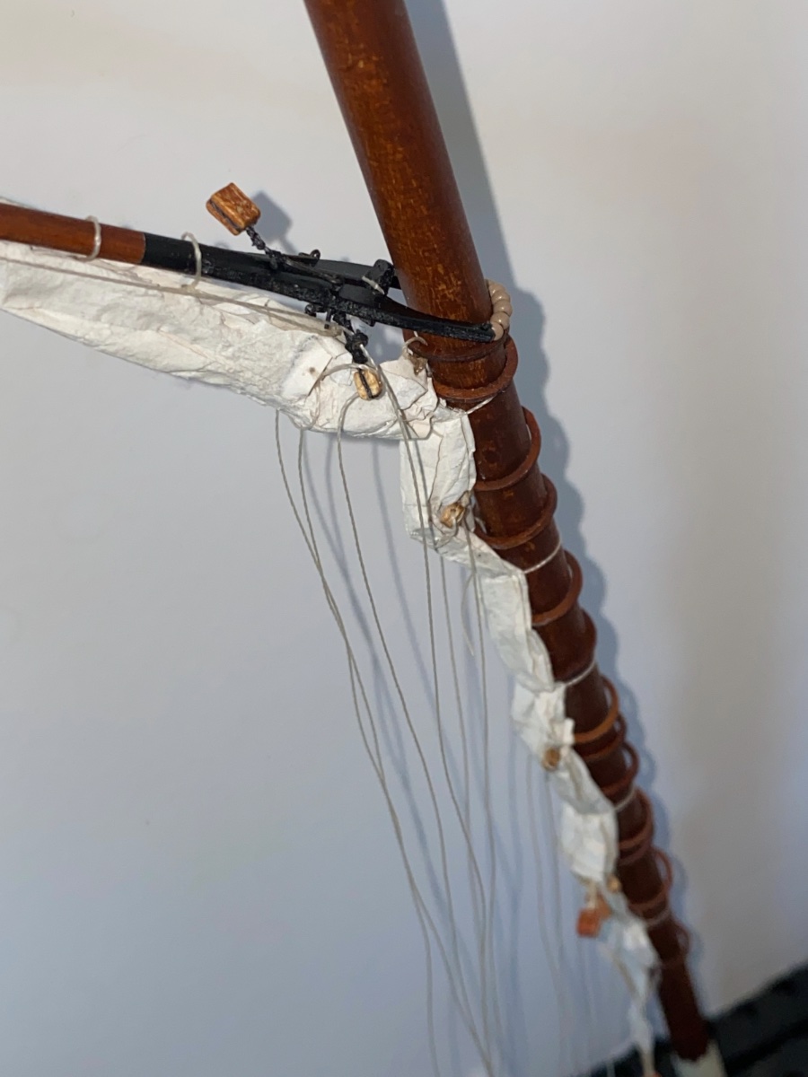
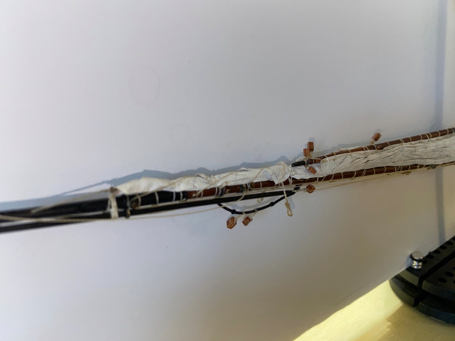
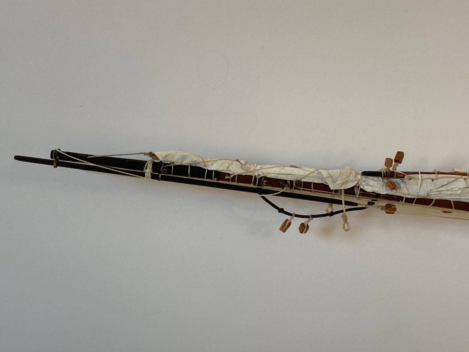
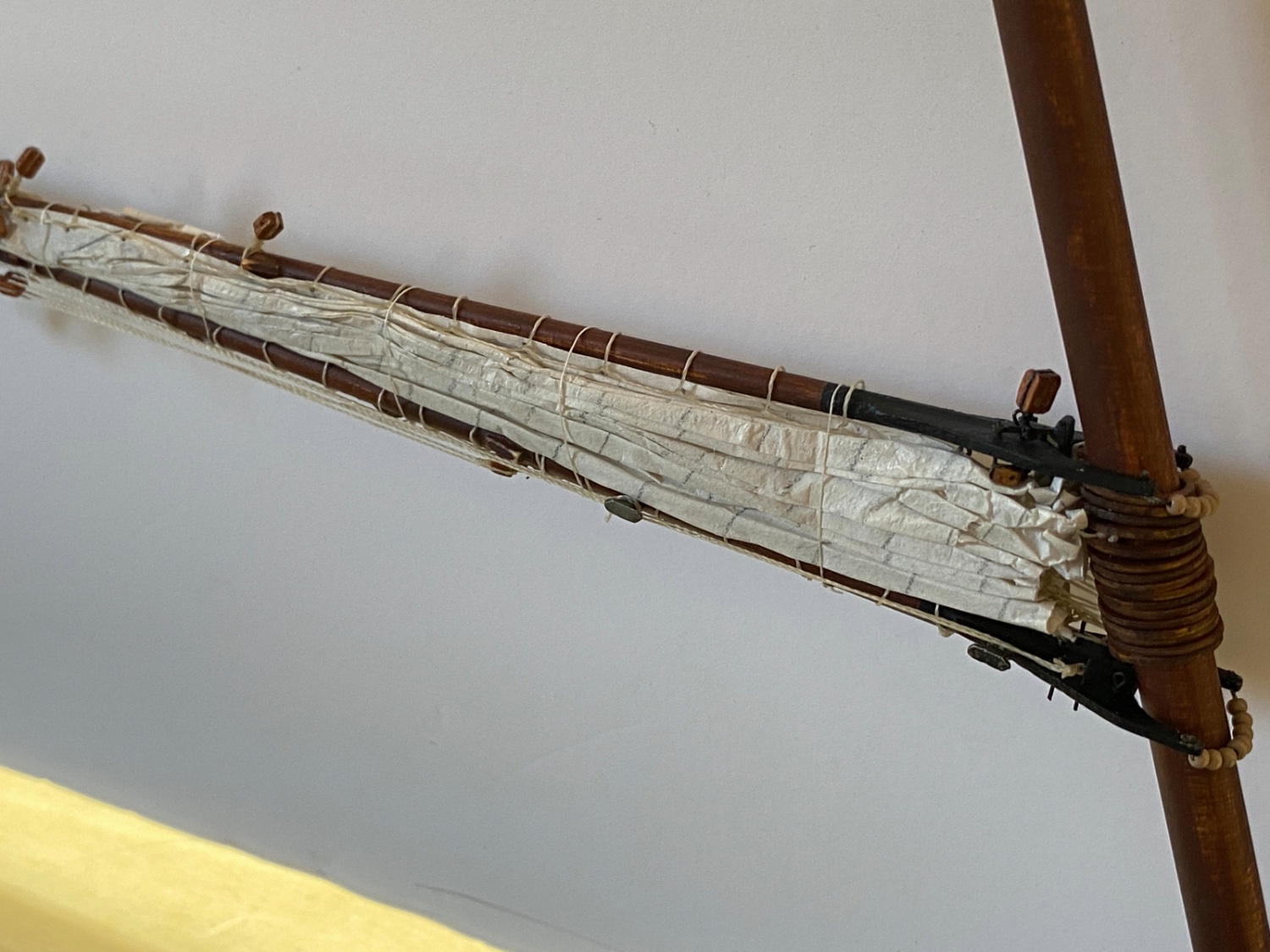
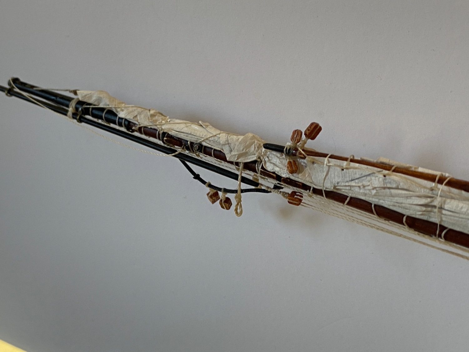
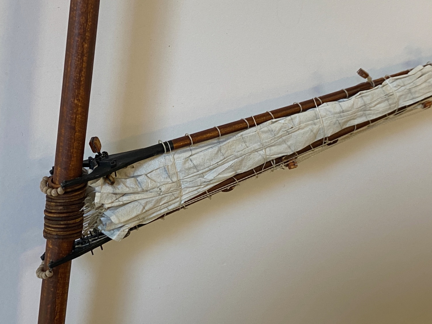
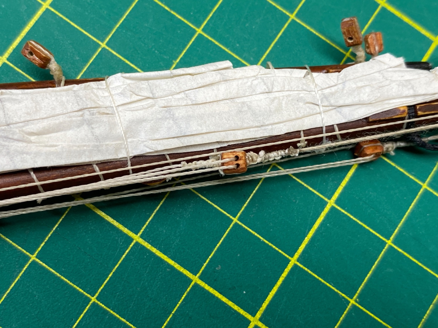
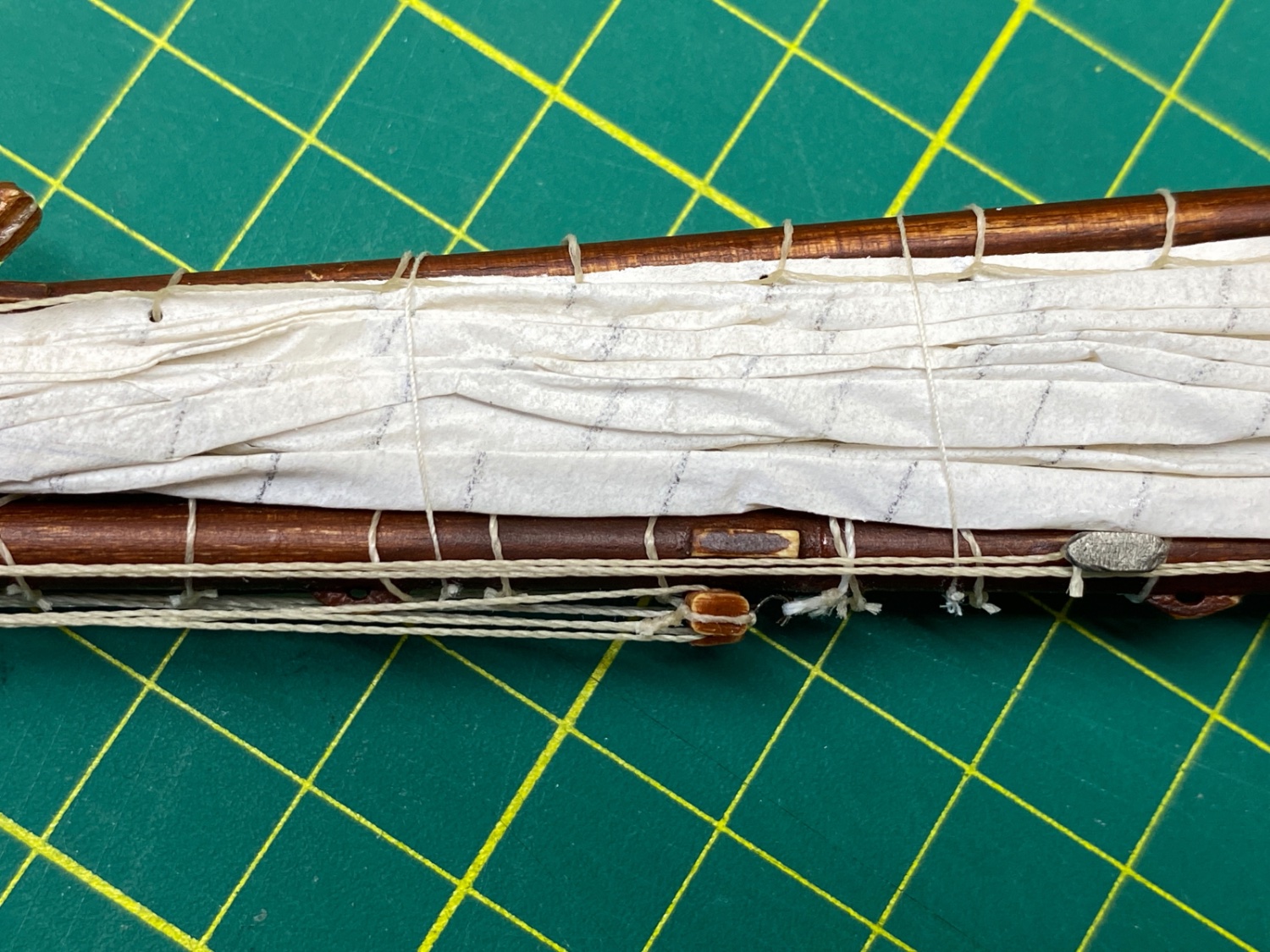
Here are some photos of the furled fore sail.
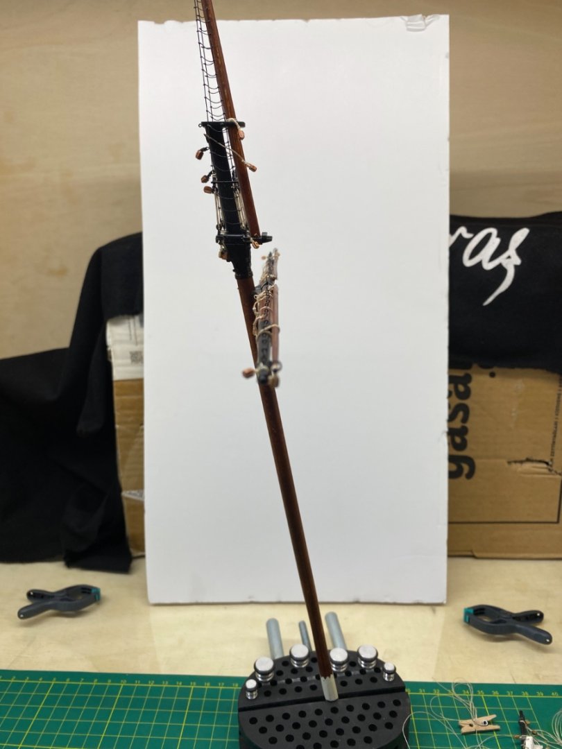
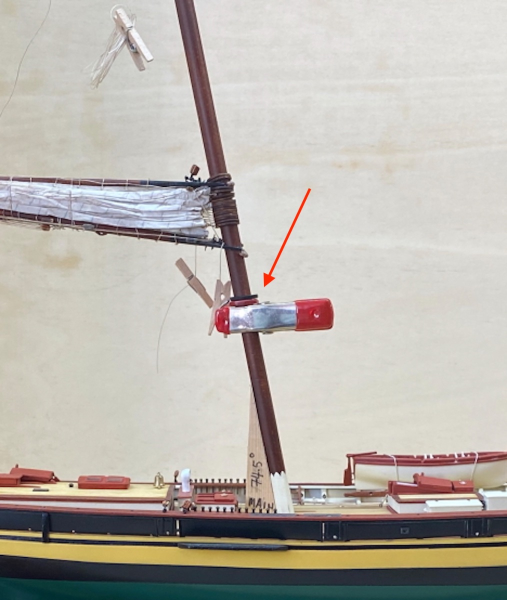
The fore mast with furled fore sail is fixed in erect position in a vise.


Here you can see the starboard head brail line passing through the metal thimble.
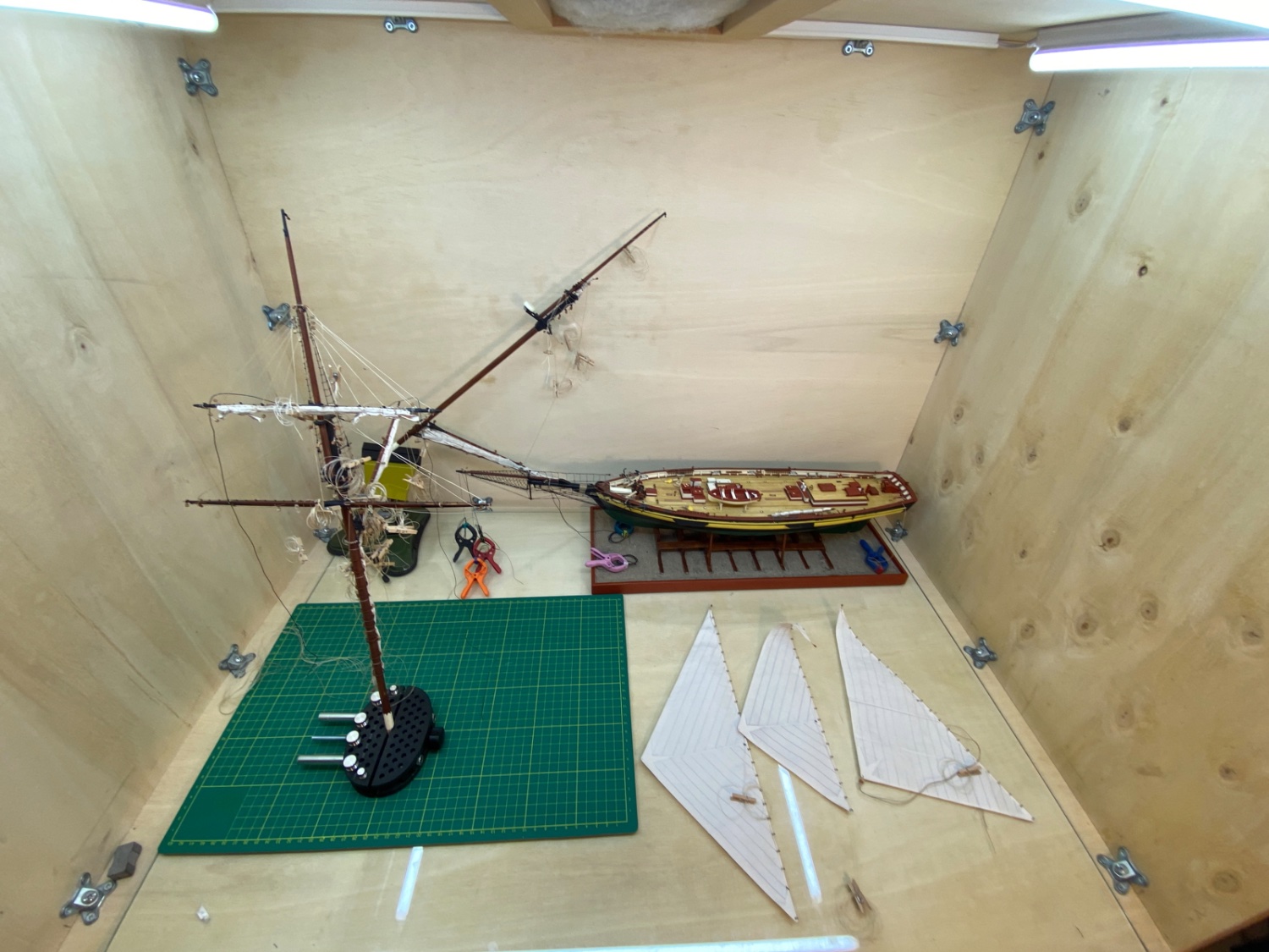
Now the Main and Fore Masts , with sails attached and furled, were finished. The next step will be installing the yards of the Fore mast followed by the installation of the masts to the deck. Fore sails will then be installed.

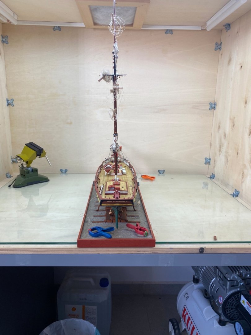
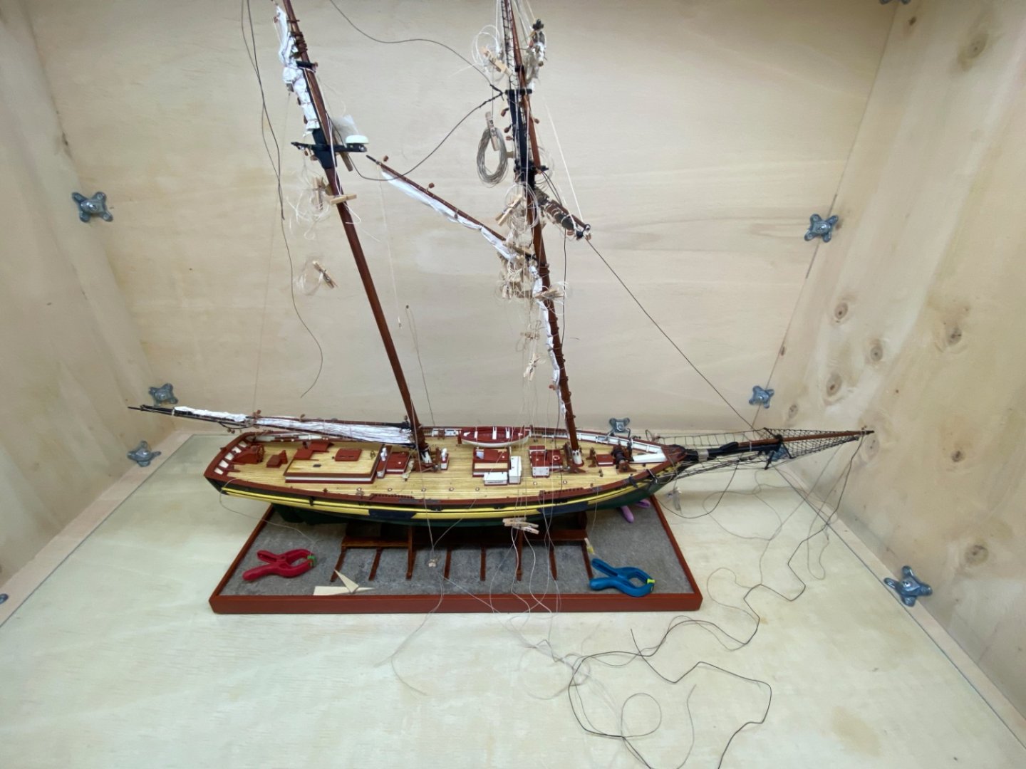
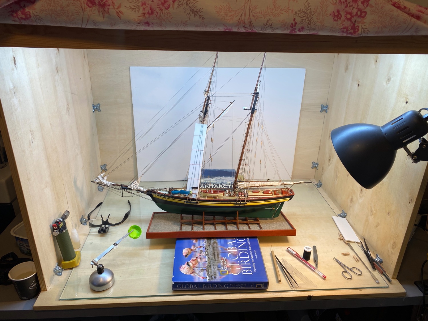
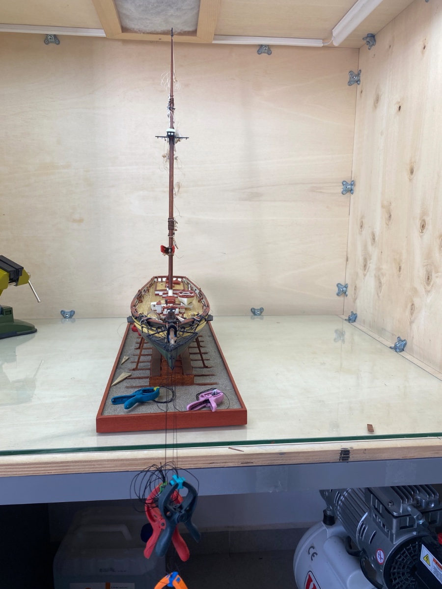
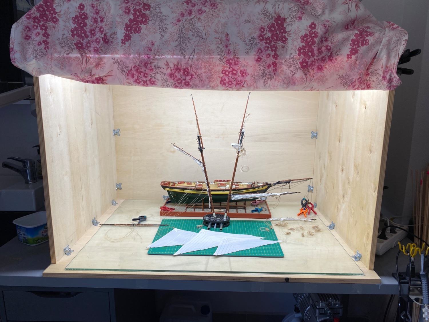
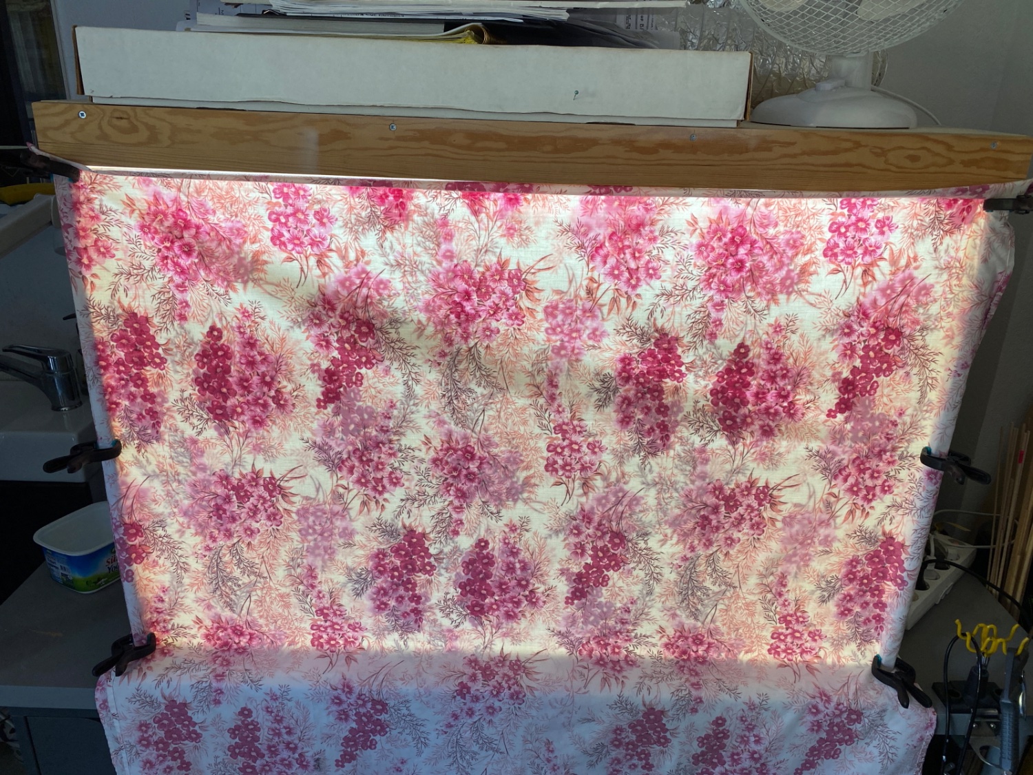
At this stage and until the end , the model is secured in the cleaned paint booth with an old cloth used as a curtain to keep the dust out...


- ccoyle, yvesvidal and Prowler901
-
2
-
1
-
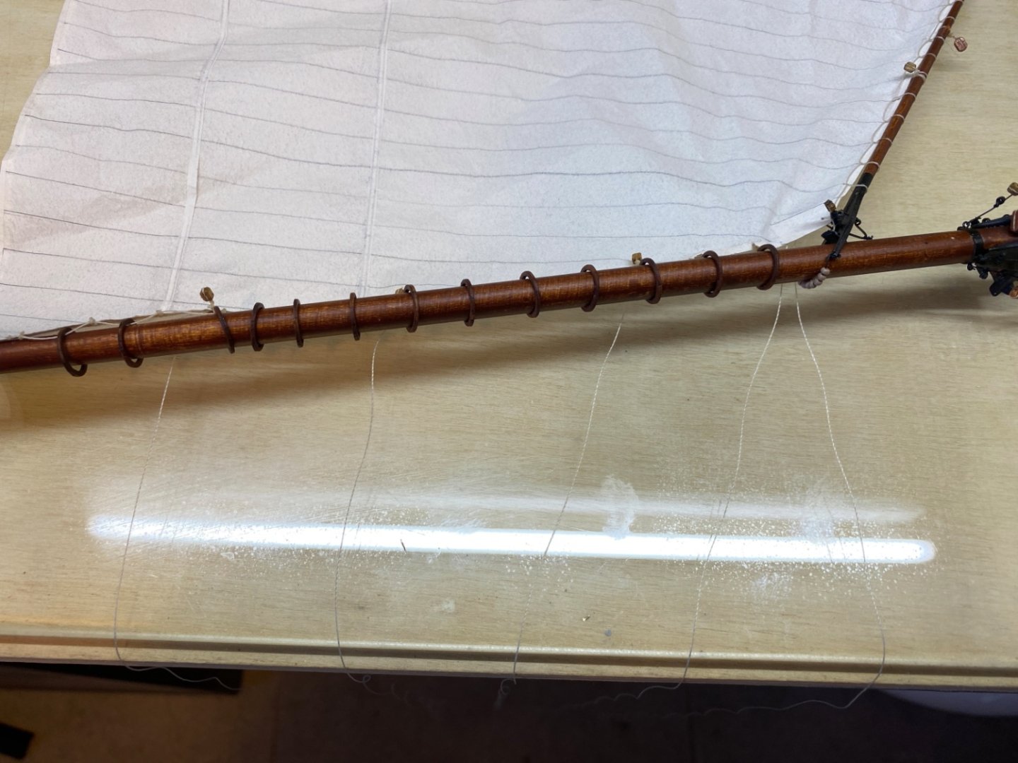
Main sail was actually done before the Main gaff topsail. However it was mounted on the main mast after the Main gaff topsail was installed. Main sail was seized to Main gaff and Main boom and furled in another setup and then was mounted on the main mast later as you will see the progress in this post.
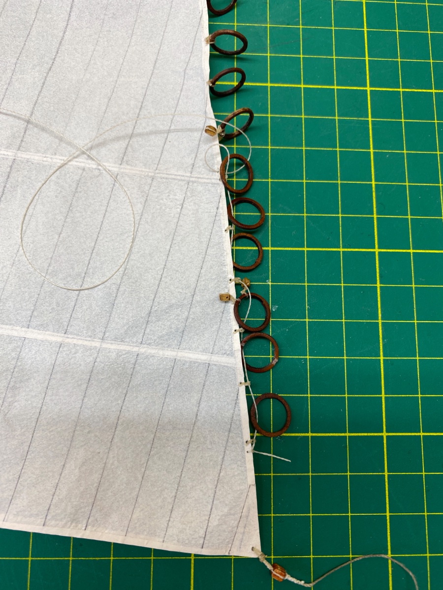
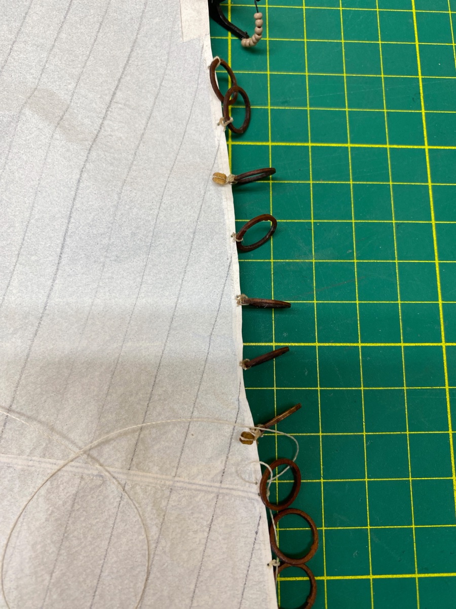
Like all the other sails, all the blocks, lines and tackles were rigged to the sail, main gaff and main boom. All the lines for seizing the sail to main boom and mast hoops were tied. All the holes for seizing the sail to main gaff and for the reef tackles were opened and strenghtened with CA glue touches. Mast hoops were seized to sail. Here an important note on mast hoop seizings was that only the hoops after the top (third) reef band were seized to main sail. All the other hoops below this level were loose and attached to the sail by a line passing through them.
Here are some photos of this step
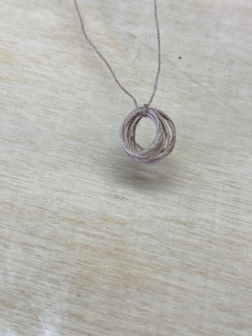
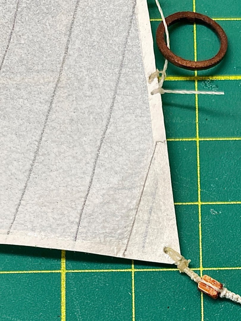
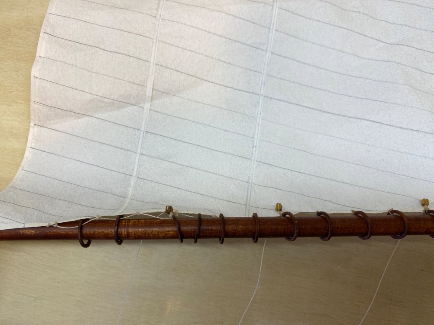
You can see in the lower part of luff no lines for seizing were tied. Instead mini thread rings were prepared for a line, mentioned above, to pass through them and hoops.

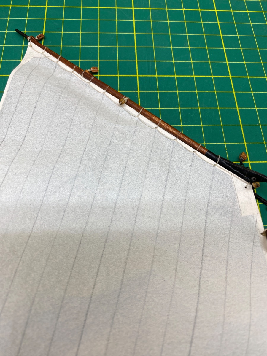
Sail was seized to main gaff by a continuous line just like the Fore Topsail. At this stage mast hoops were already seized to the sail.

Here are some some photos after the sail was seized to main gaff. The sail was mounted on the main mast.
Close up photo of the Main Gaff rigging blocks


Mast hoops seized to sail.
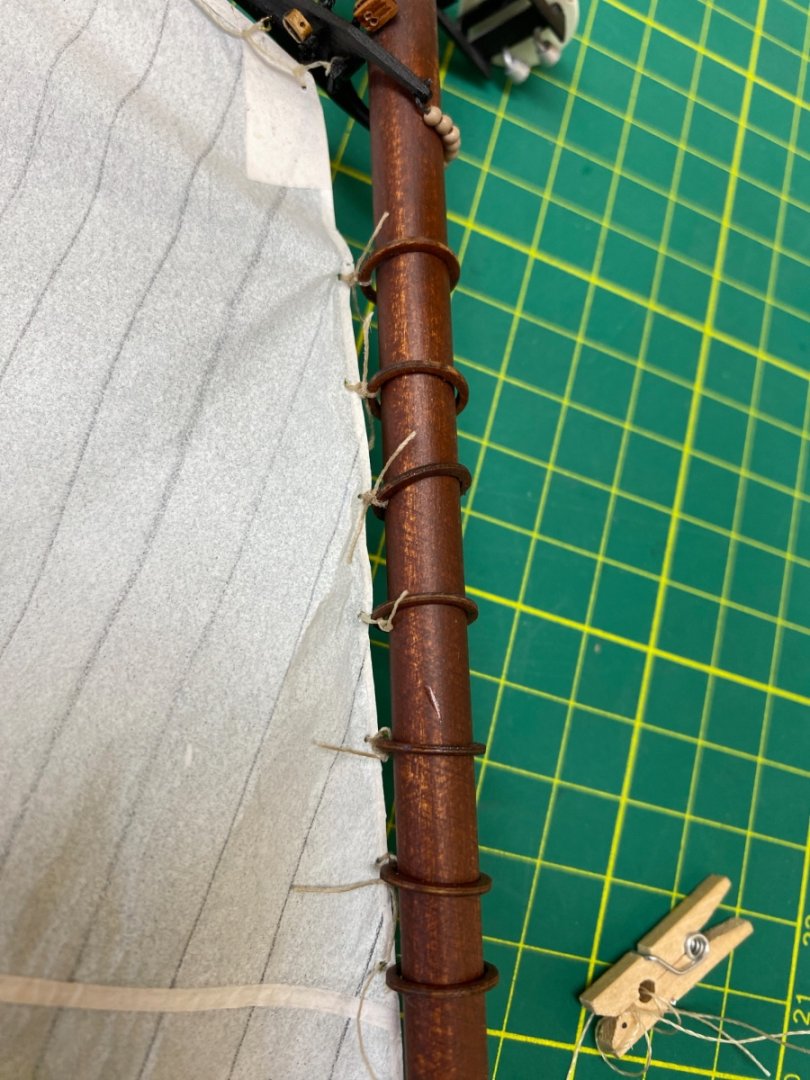
Mast hoops attached to sail by a line passing through them.

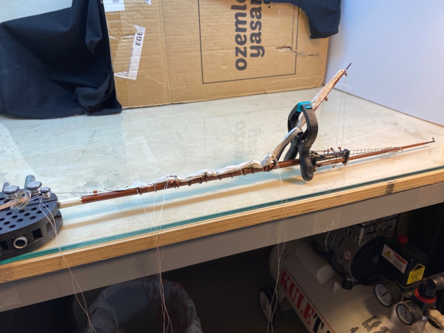
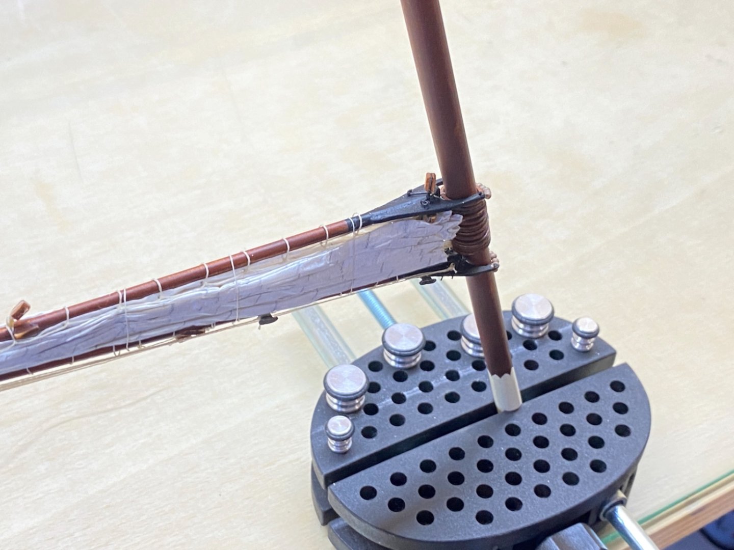
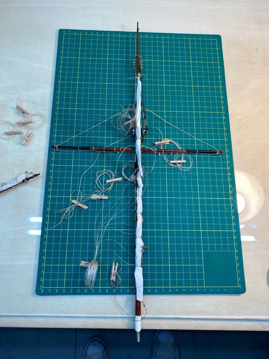
The next step was seizing the sail and the main boom. The sail was removed from the main mast for this step. Main boom seizings were individual ones and must be loosely tied. That means there must be a space left between the boom and the seizing. In order to achieve this space a wood strip was used when tying the seizings.
Here are the photos of this step.
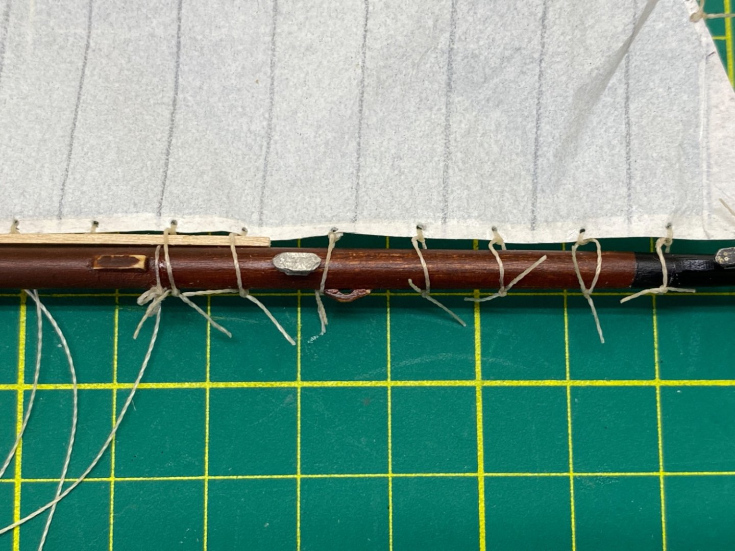


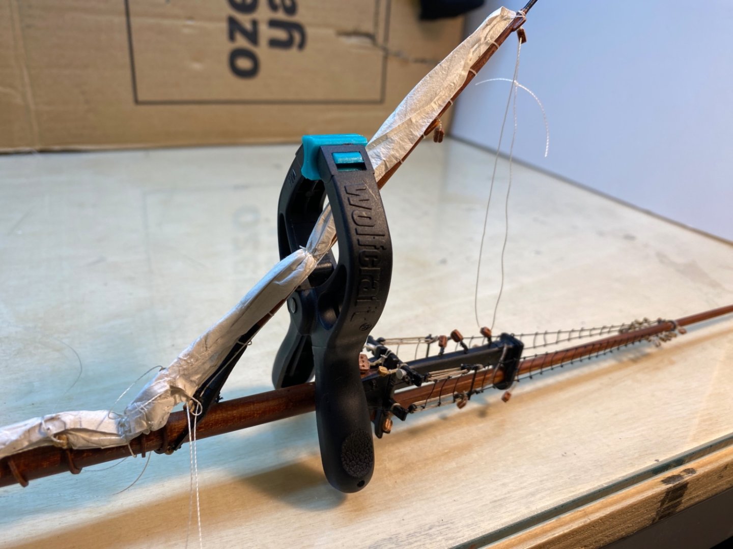
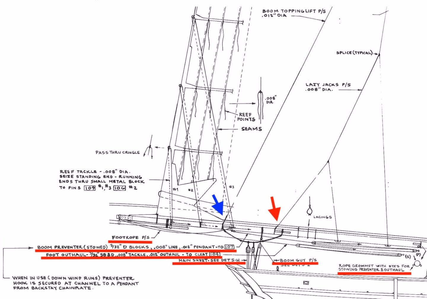
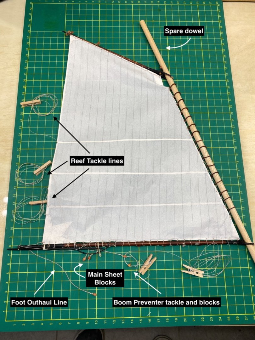
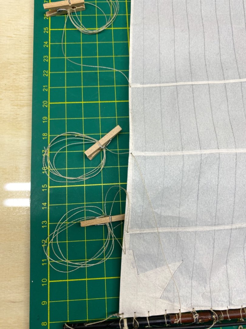
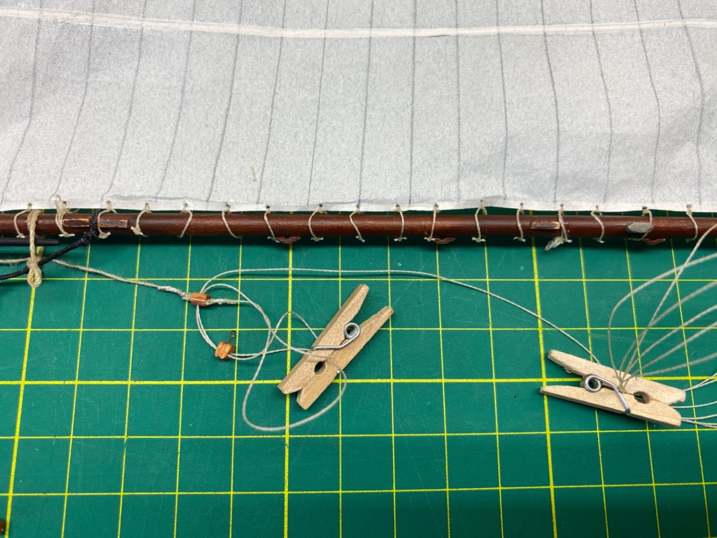
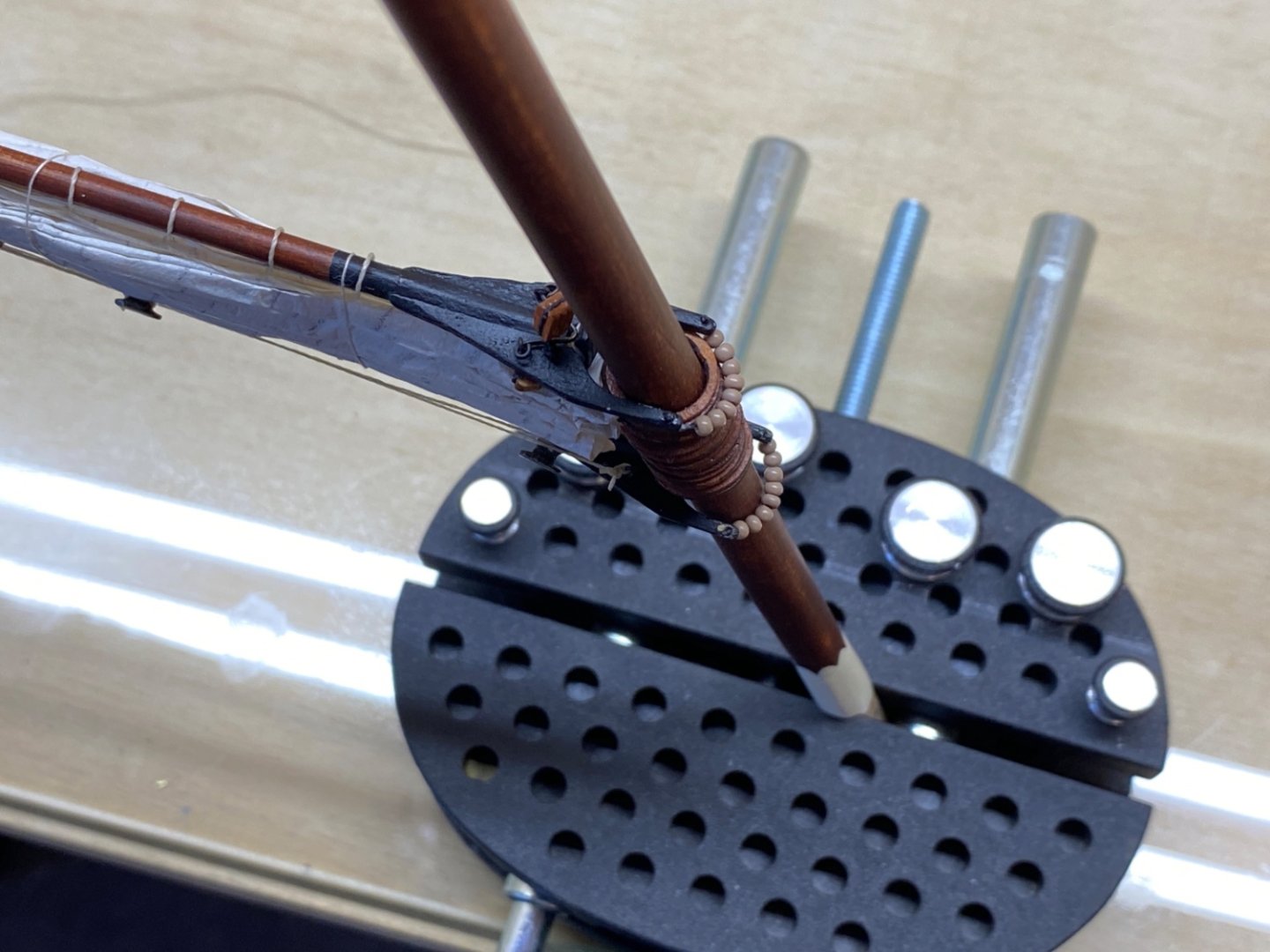
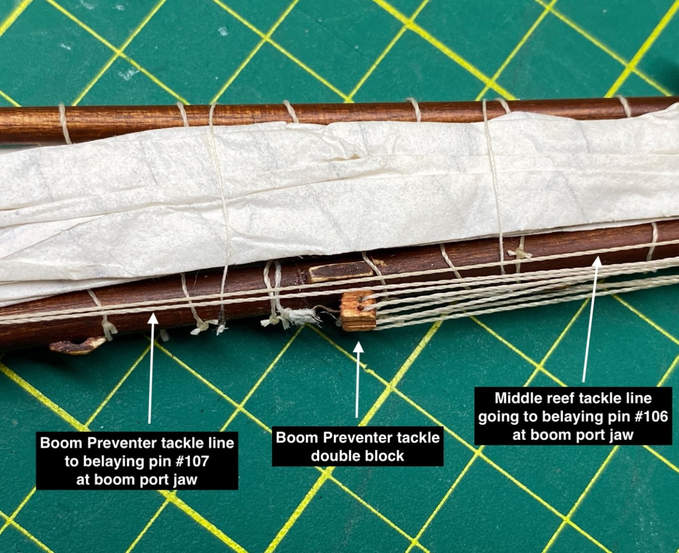
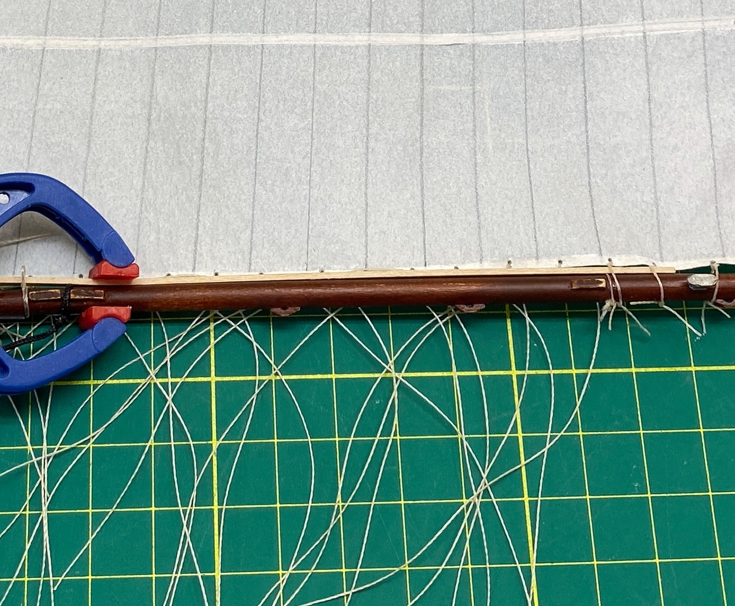
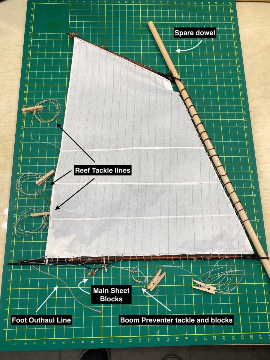
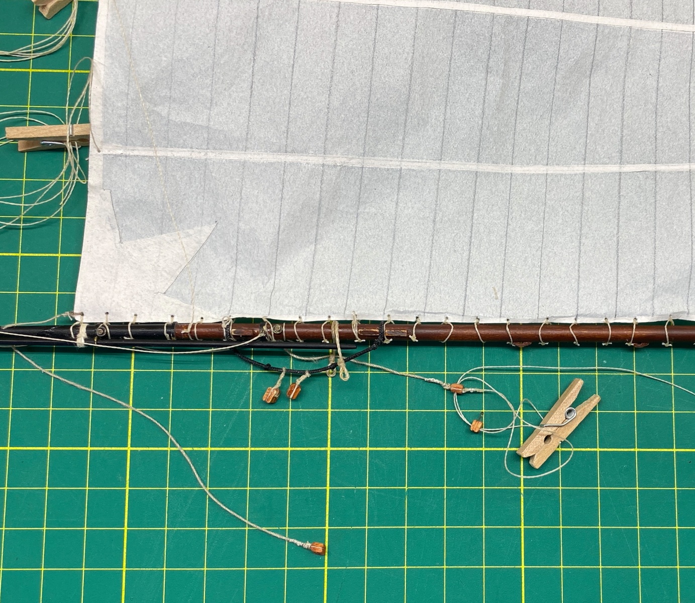
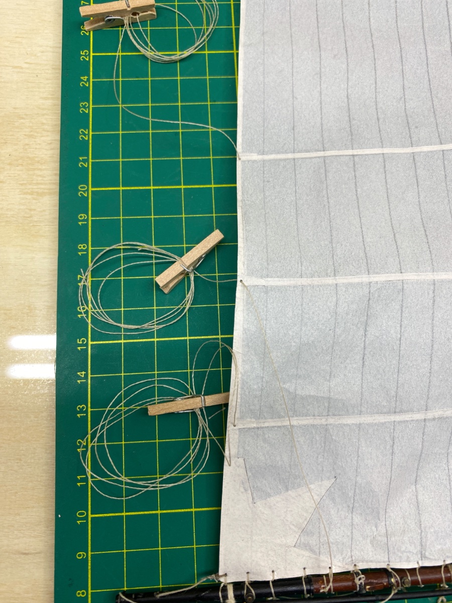
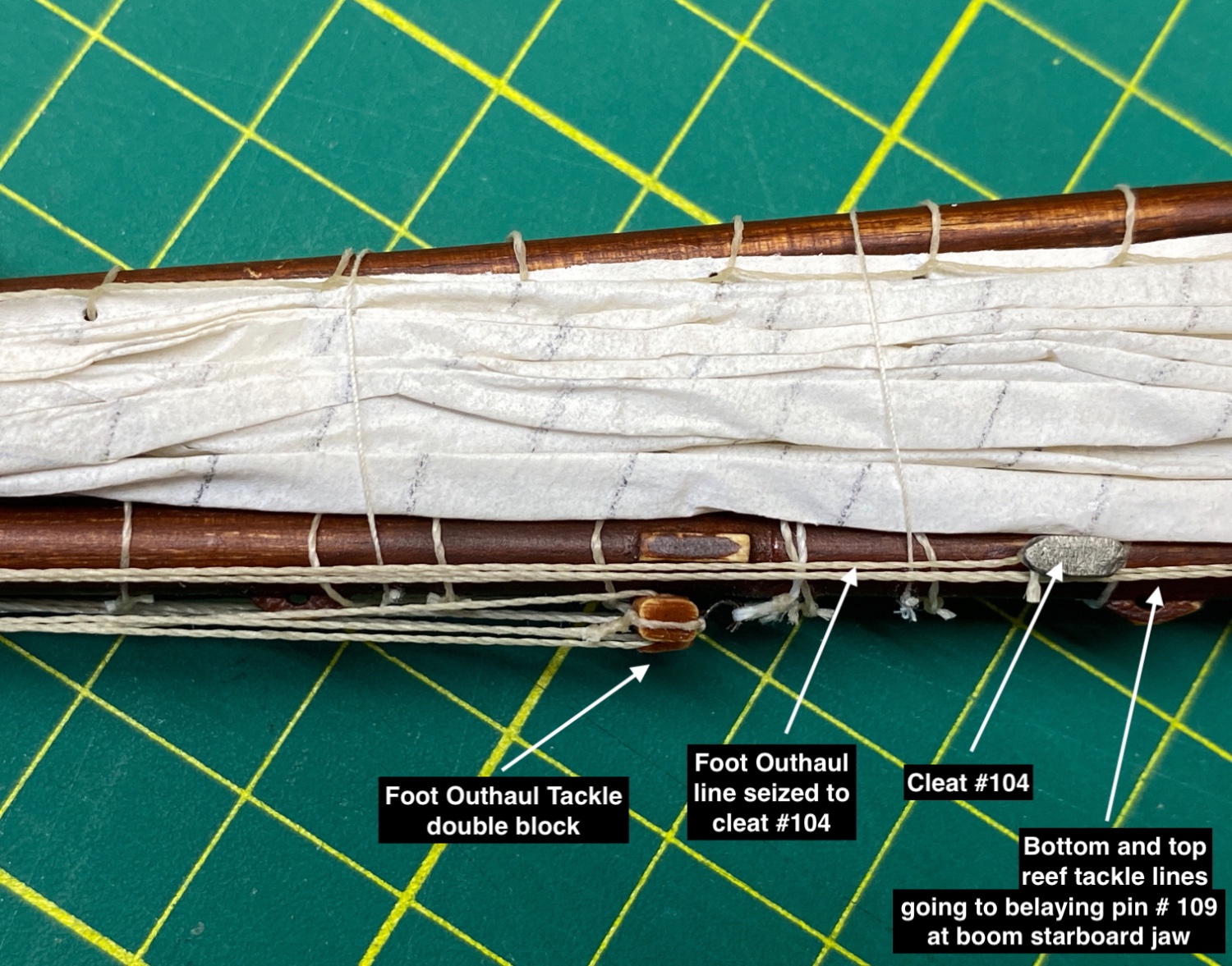
After the sail was seized to main boom , a smaller diameter, than the main mast , dowel was inserted through the mast hoops. Three reef tackle lines were seized. Also the rigging and tackles for Boom preventer and Foot outhaul were installed. Here is a photo of main boom rigging from the plan followed by the photos from the model. Blue arrow indicates the seizing point of starboard Boom Topping Lift. Red arrow indicates the seizing point of starboard Lazy Jack.


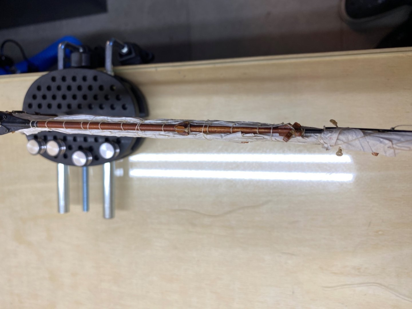
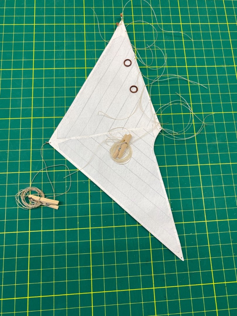
Then the sail and dowel were fixed. The sail was hoisted up with a temporary line reeved through the block at the peak side of the gaff. Here you see the setup

Then the furling process began. I began wetting the sail with water applied by a cut brush and starting from the foot. Wetted sail was folded on the main boom and at the same time loosening the temporary line above. At this step I tried to make the fold as natural as possible. However any imperfections can be handled later as long as the sail is wet and not dried. After the desired furling of the sail between the main boom and main gaff was achieved a couple of overhead knots were tied to stabilize the sail. Here are some photos of these steps

Here you see some extra lines. They were also temporary (simulating boom lift and lazy jacks !) and for keeping main gaff and sail aligned by main boom .


Then the sail and spar block was removed from the temporary dowel and transferred and mounted to the main mast.


Here are some more photos with the sail spar block laid on a cutting mat.


As the main sail was furled, Vang line must be coiled and stowed on the main boom. Here are two photos of that area before and after the sail was weathered by dry brushing.
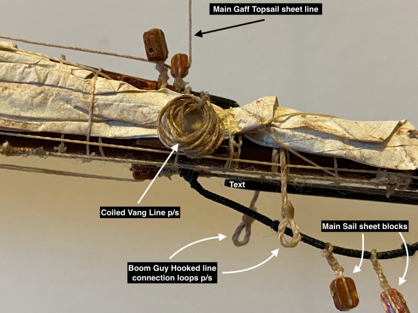
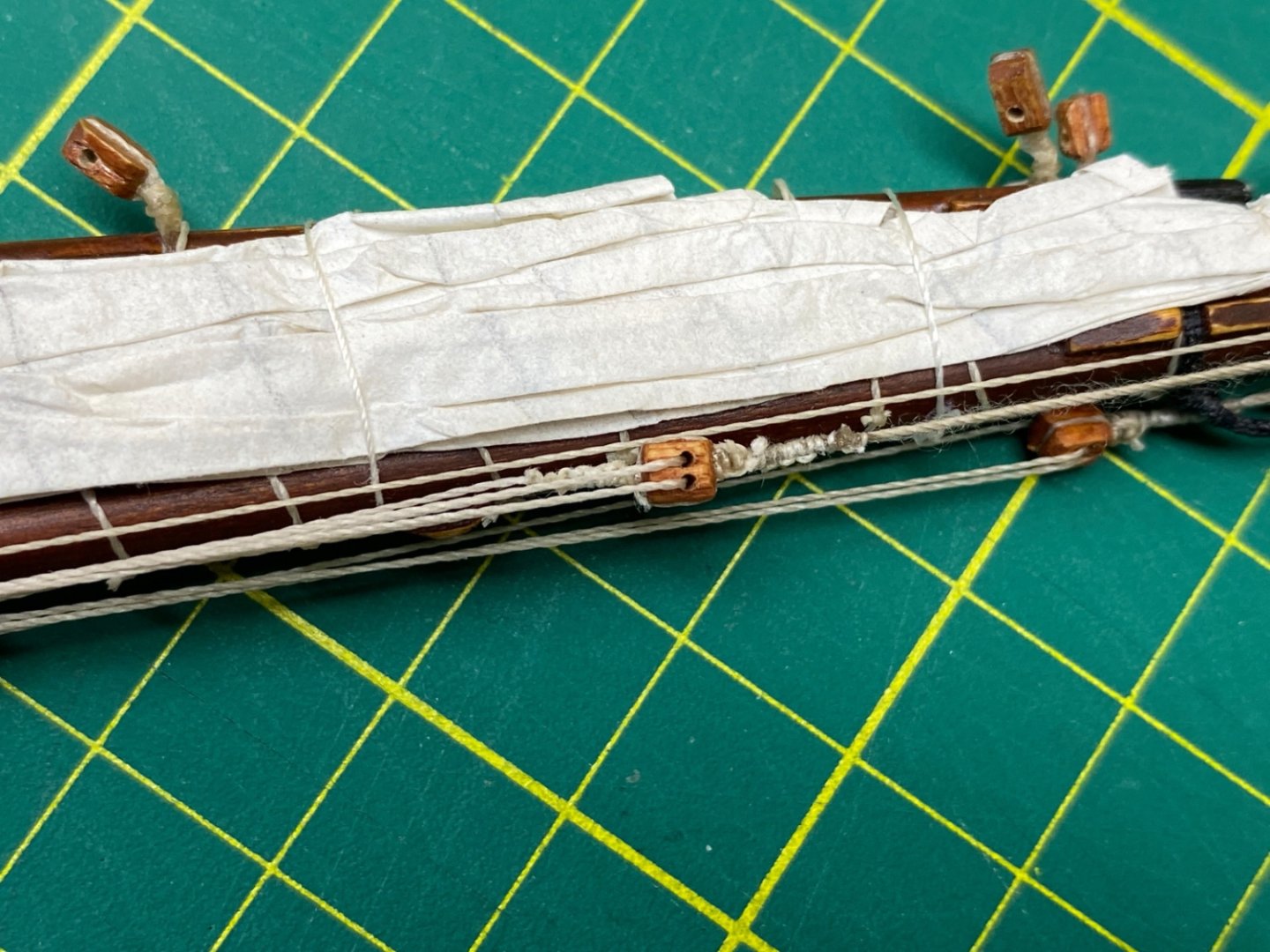
Here are some photos of the Main Boom, furled Main sail and Main gaff with legends.
Starboard view
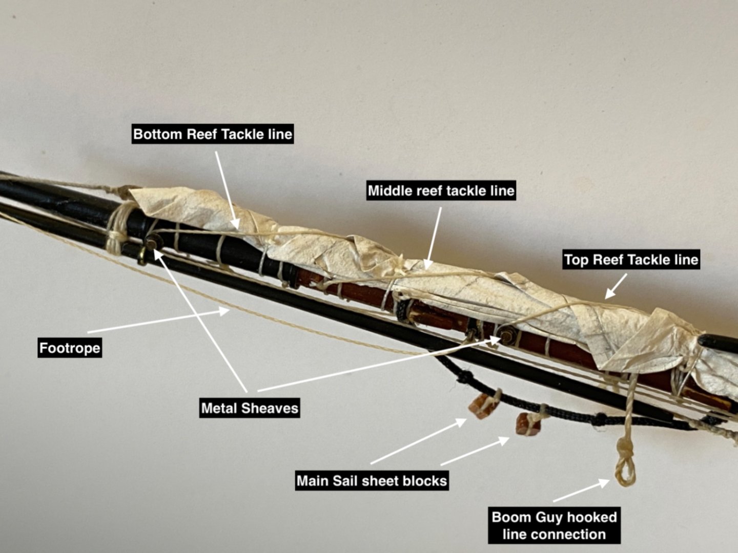
Starboard view

Port view
At this step main mast sails, main sail and main gaff topsail were installed and furled. The main mast was put aside and protected.
- Prowler901 and yvesvidal
-
2
-
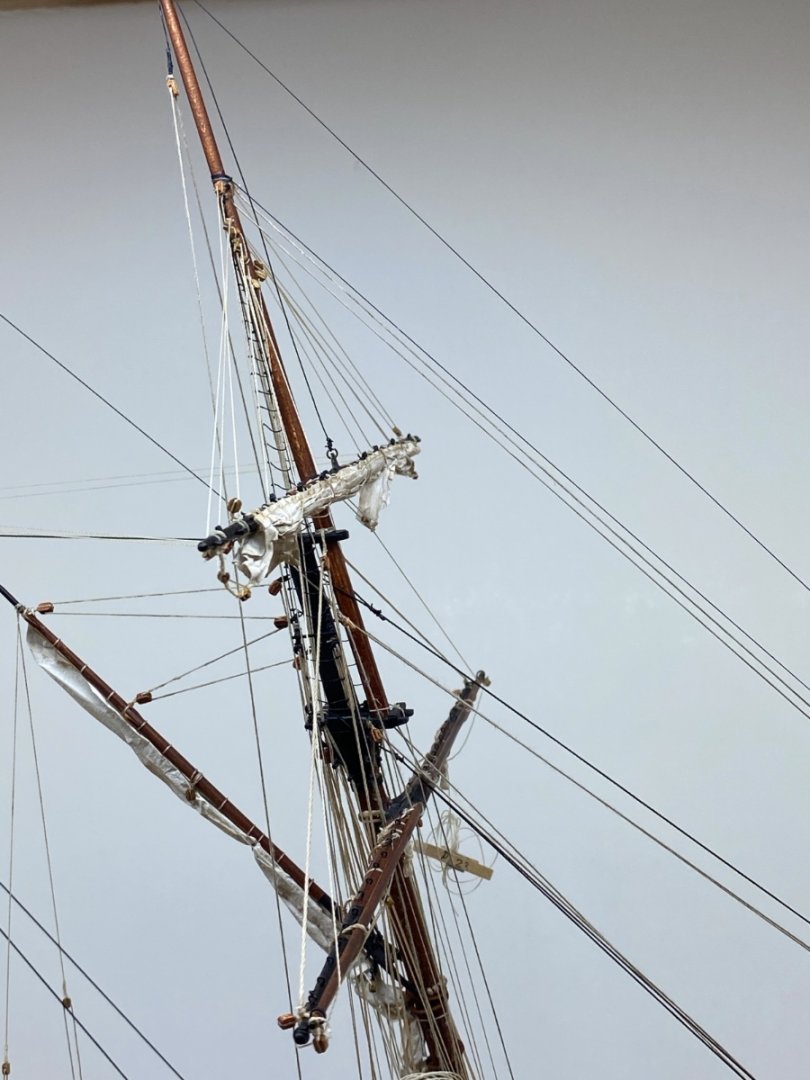
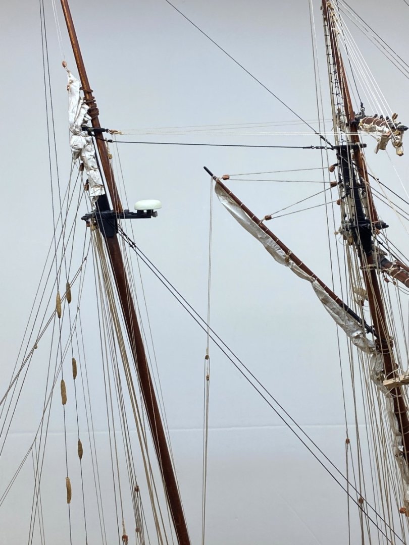
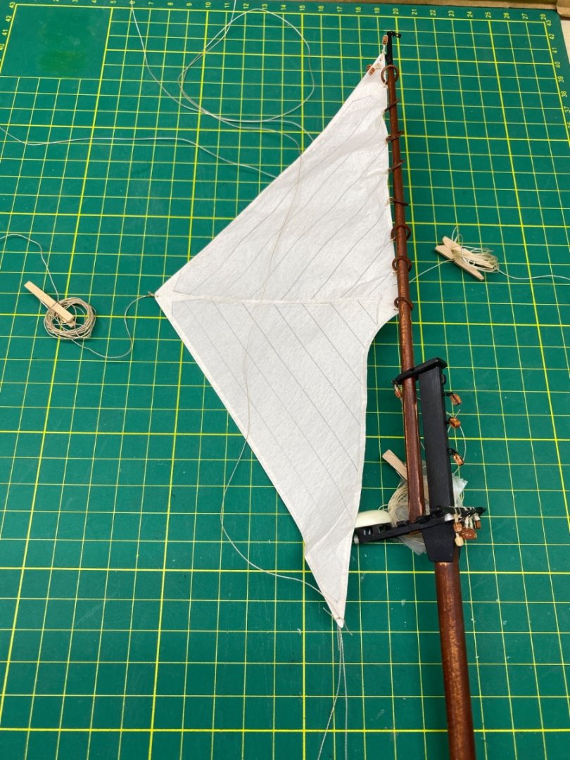
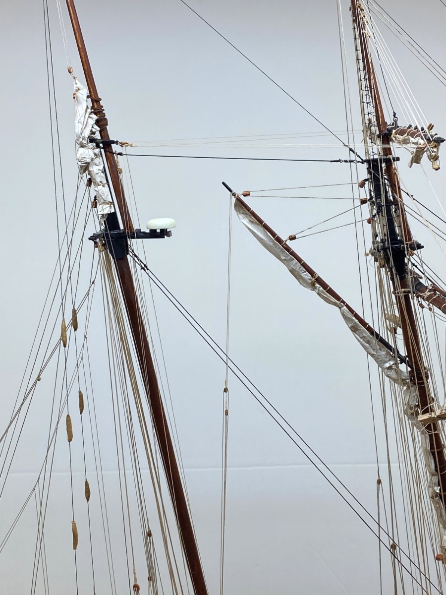
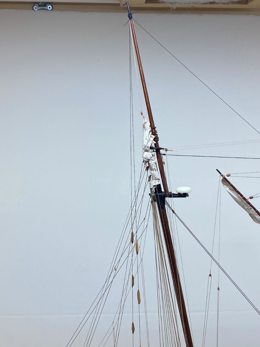
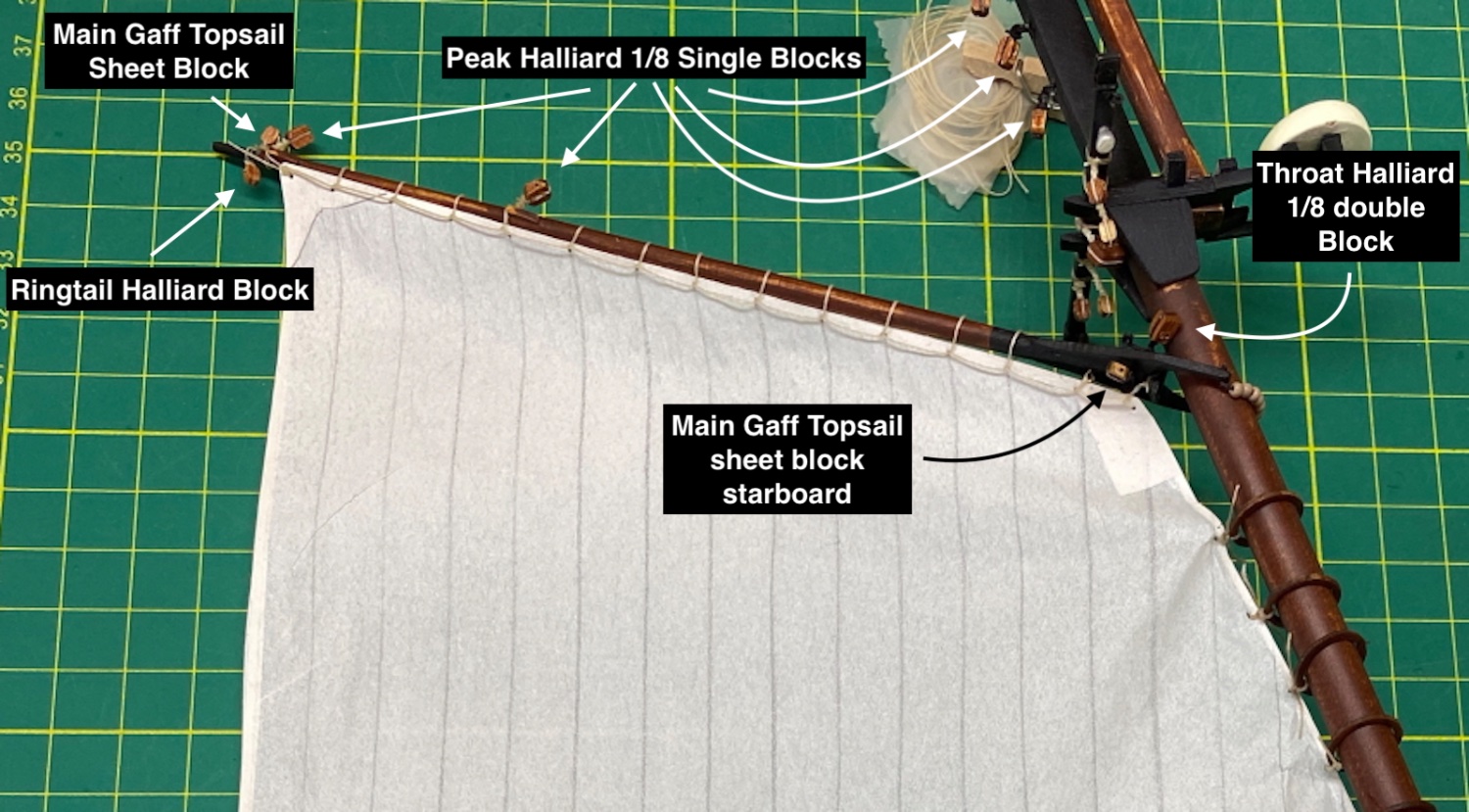
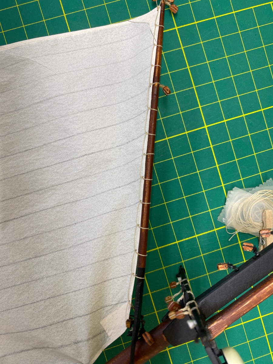
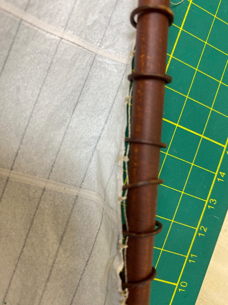
The third sail I prepared was Main Gaff Topsail. Just like the Fore Topsail I prepared and seized all the rigging blocks, lines and mast hoops (small ones) of Main Gaff Topsail. In the photo below you can see them. Mast was laid in wrong position though and it must be flipped 180 degrees and the radar dome must face towards .
Head of the sail
Aft clew. On the port side of the sail there is a block for reeving fore clew uphaul line (Dotted red line)
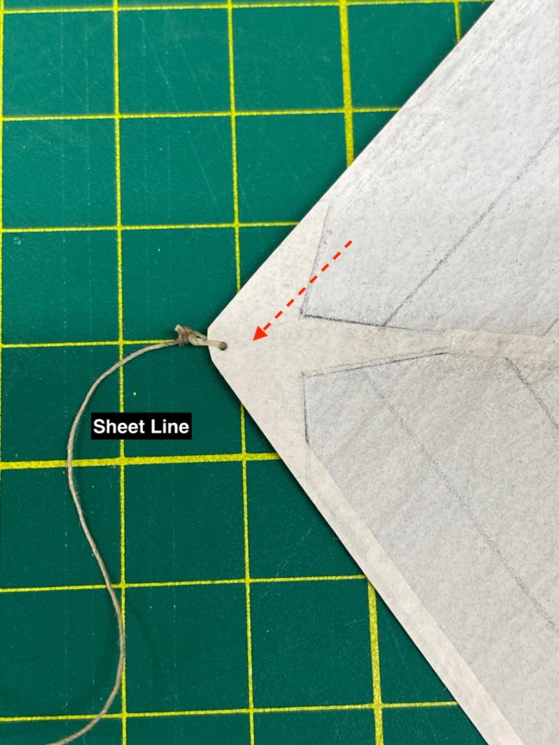
Fore clew of the sail and the origin of the clew uphaul line
The sail installed on the main topmast and the setup for furling. Protected hull is in the box in the background. Red arrow indicates the block for reeving clew uphaul line on the port side of the sail.

Closeup view. Red arrows show the line for clew uphaul and its hidden ! block.
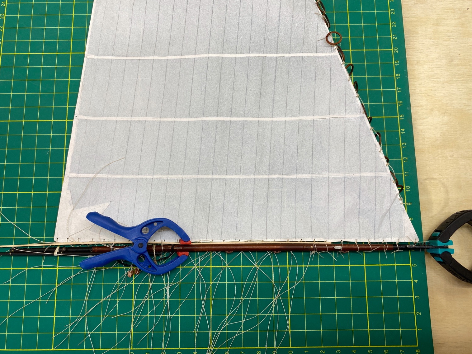
The photos after the sail was furled and tied.

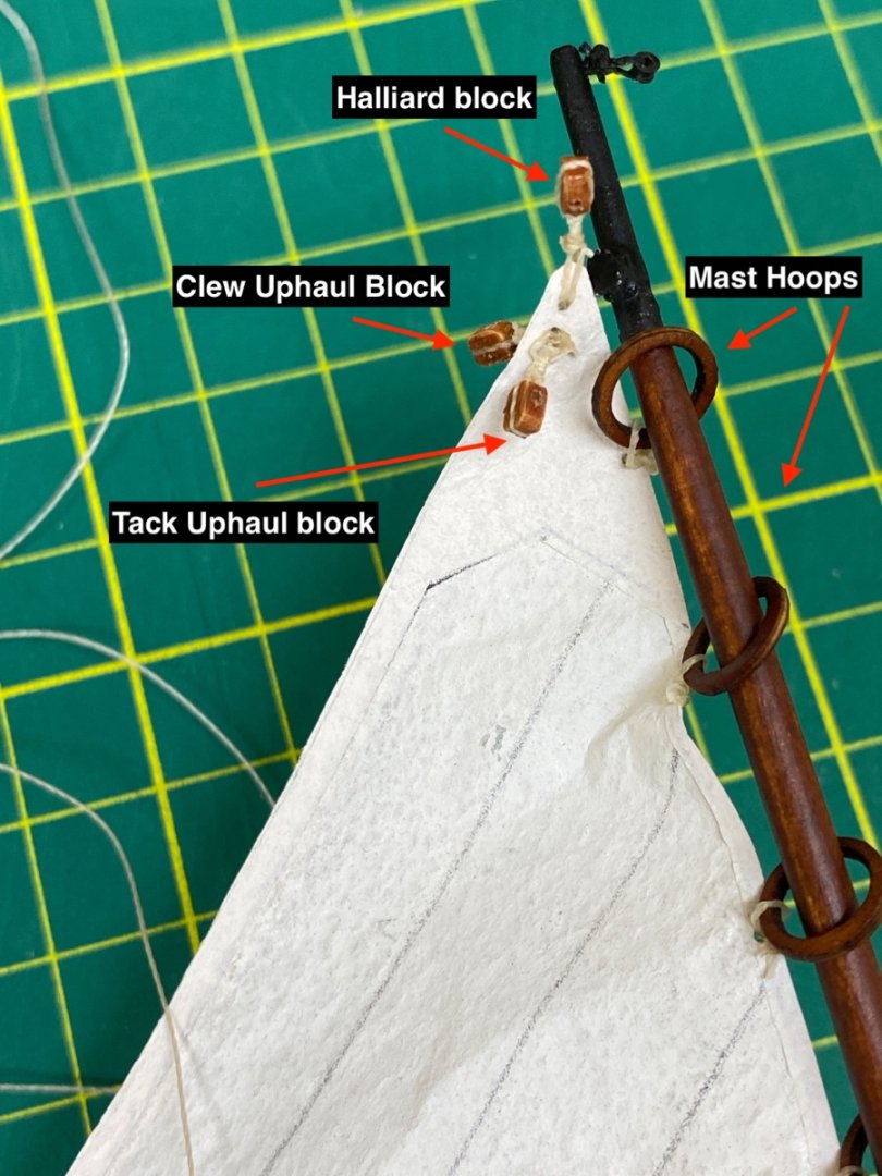
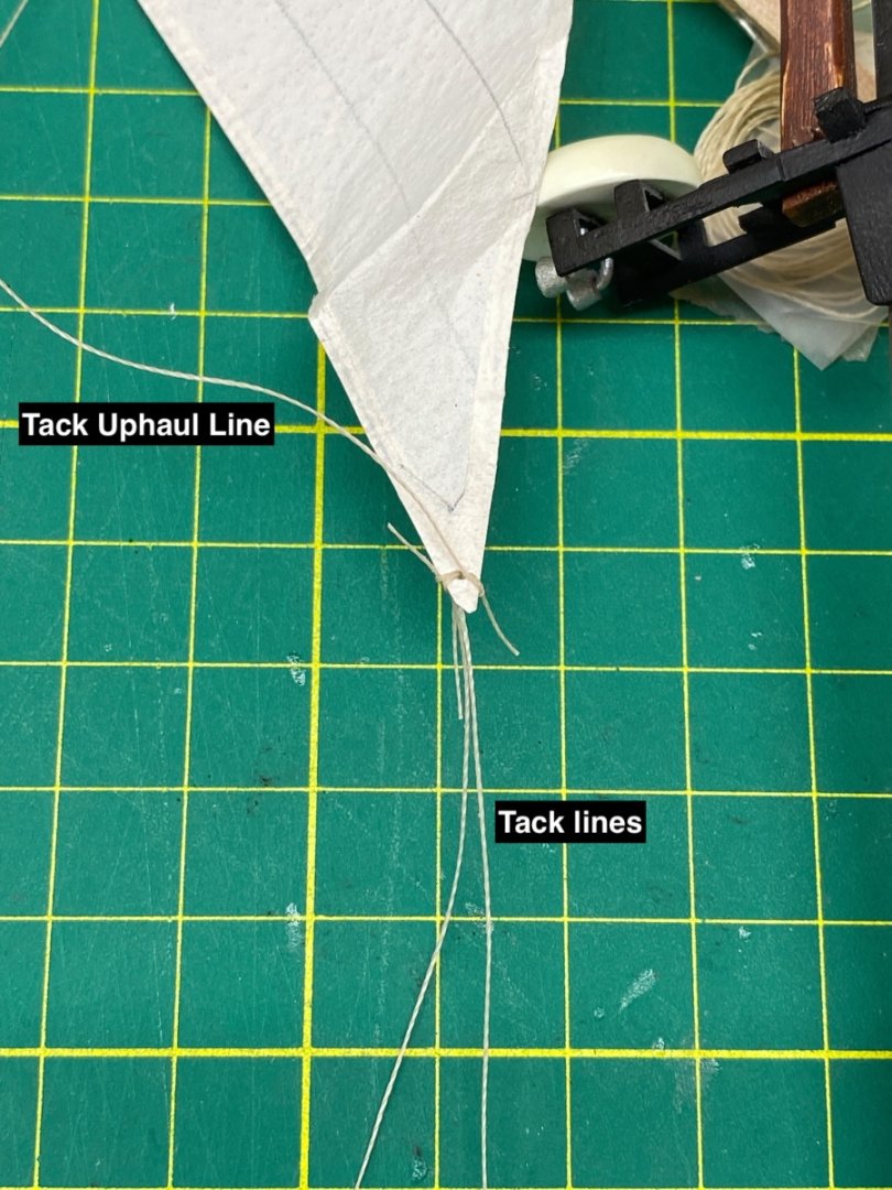
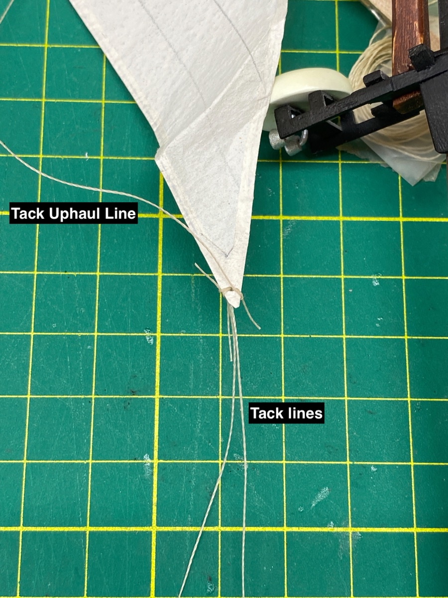
Although not shown here, the halliard line originates from the topmast just under the topmast sheave, reeves through the block at the head of the sail and turn upwards and reeves through the sheave in the topmast . Below the halliard block and the tack uphaul block with their lines reeved.

Some other photos


- ccoyle, Paul Le Wol, Prowler901 and 1 other
-
4
-
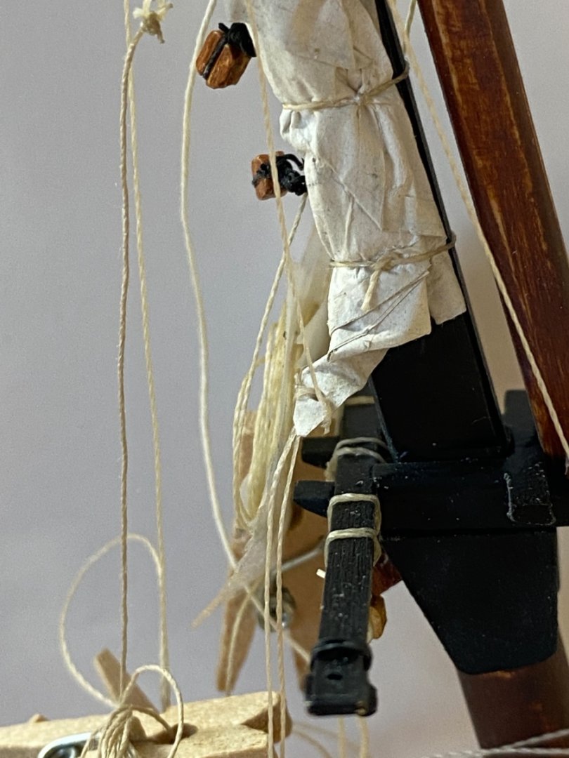
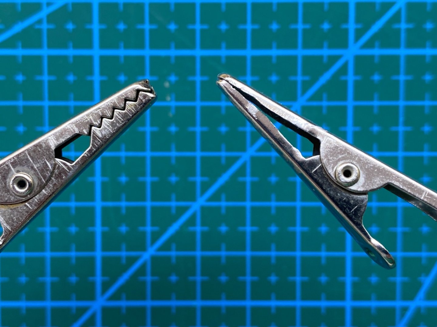
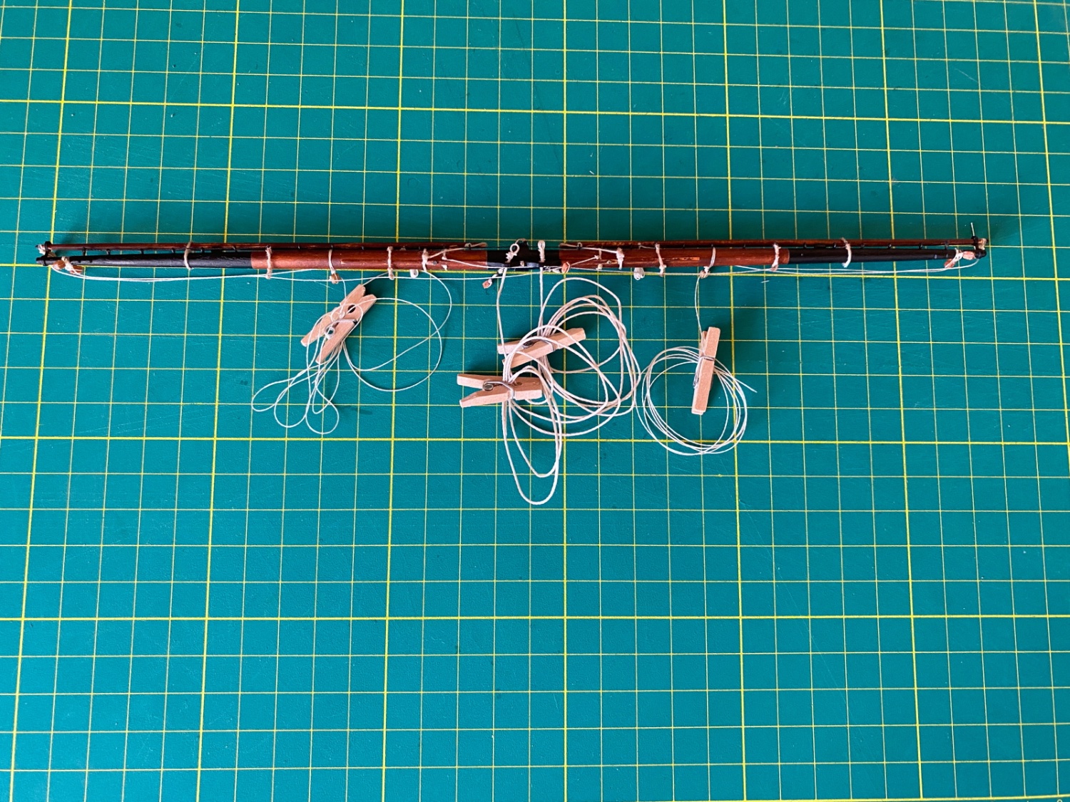
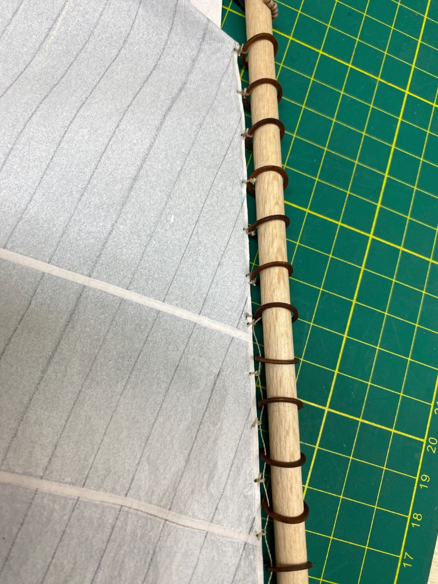
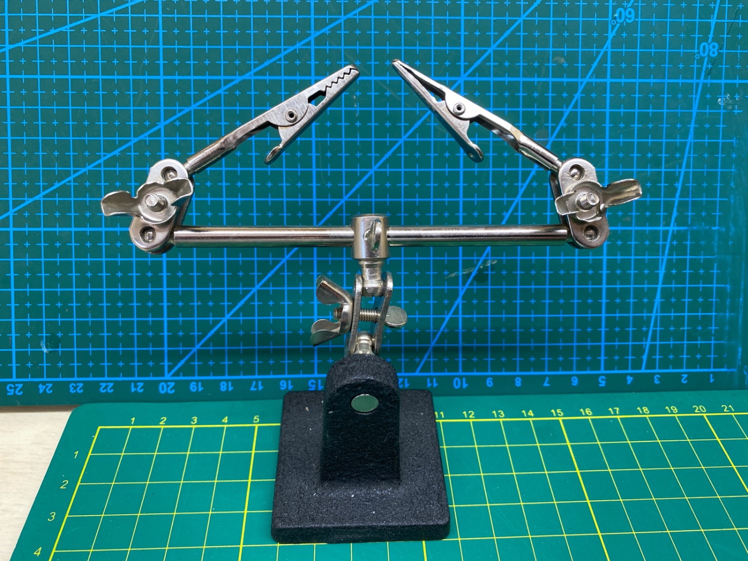
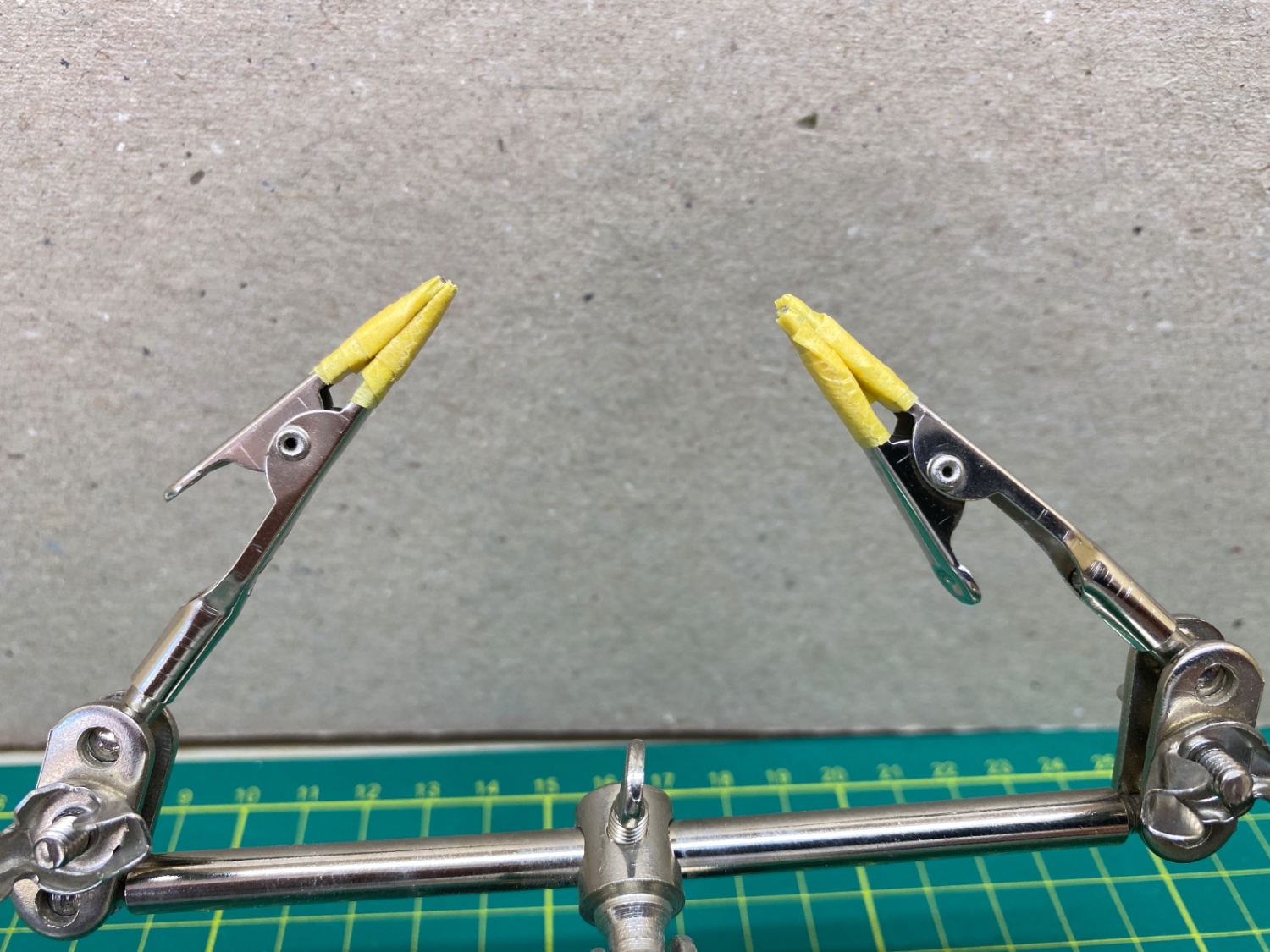
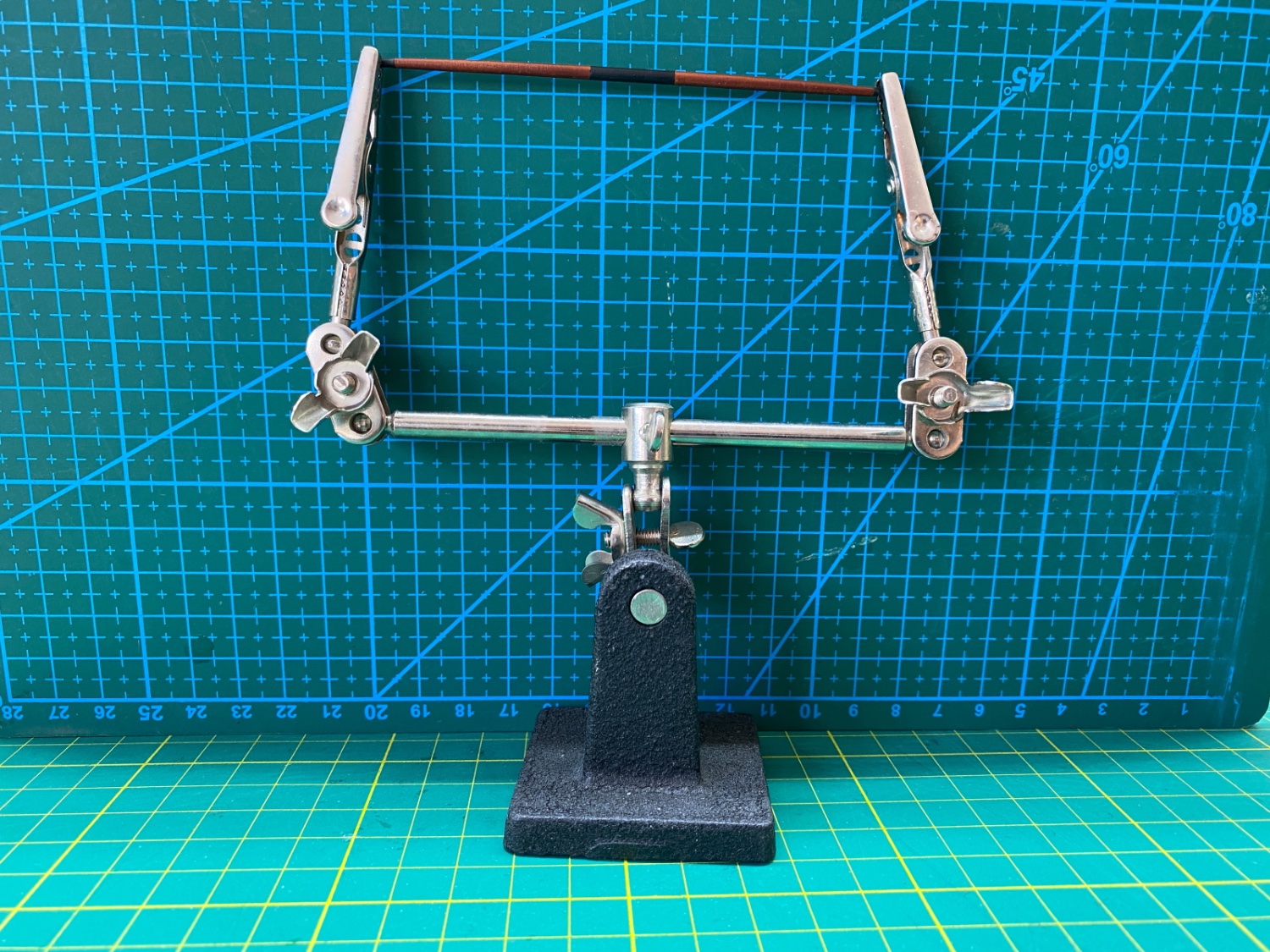
The second sail in line was Fore Topsail. Before beginning to seize the sail to fore topyard the tips of the alligator clamps of the two arm holder were modified in order not to damage the yard arms.
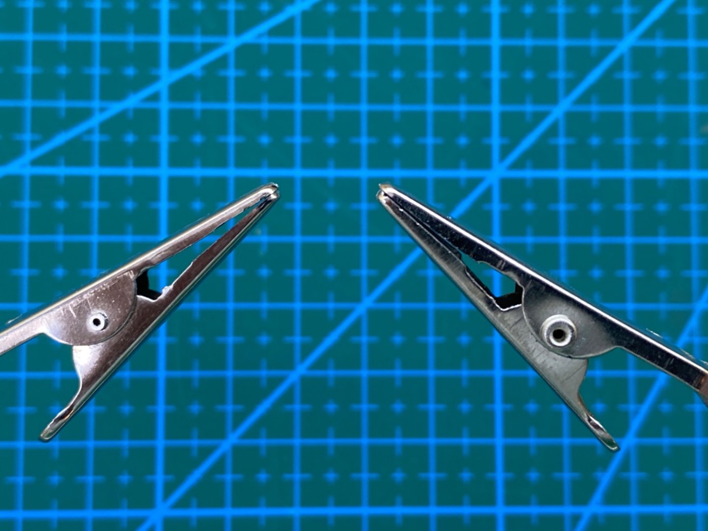
The teeth of the clamps were filed and they were later covered with masking bands.


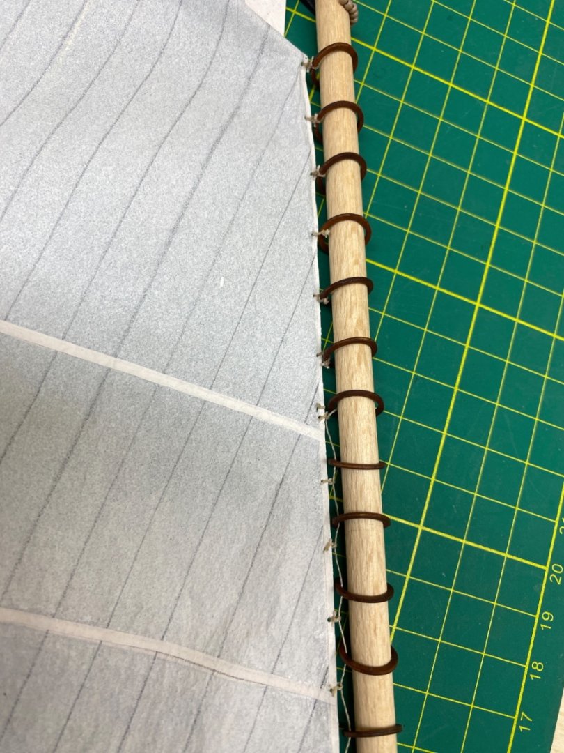
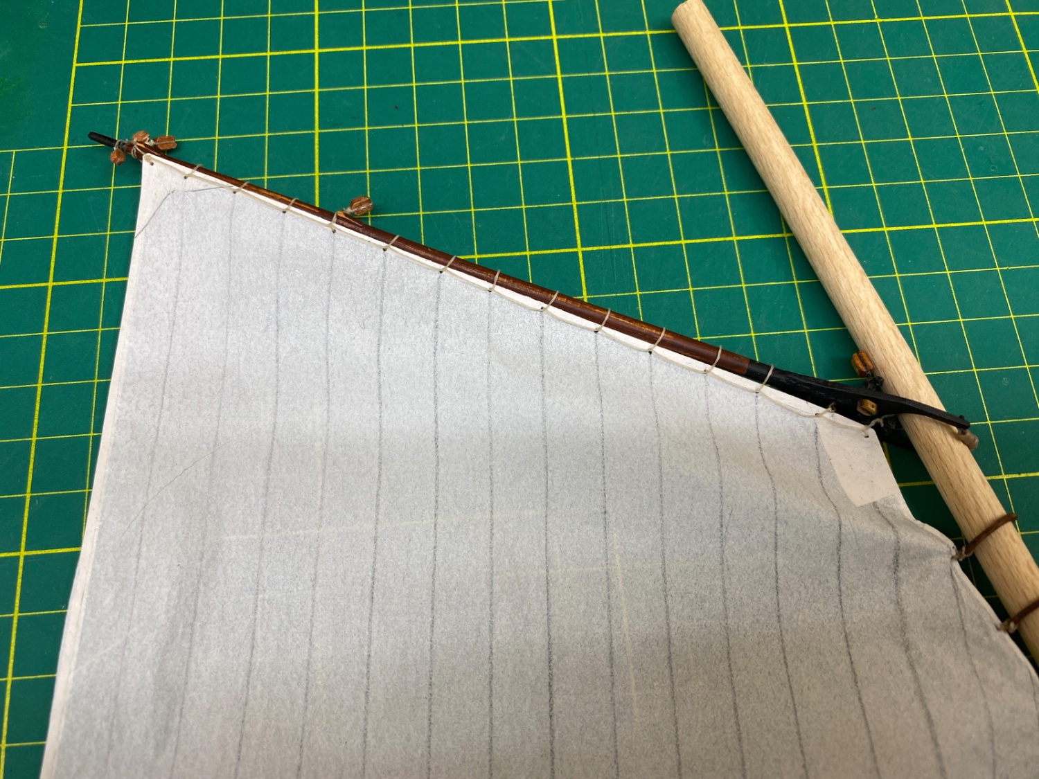
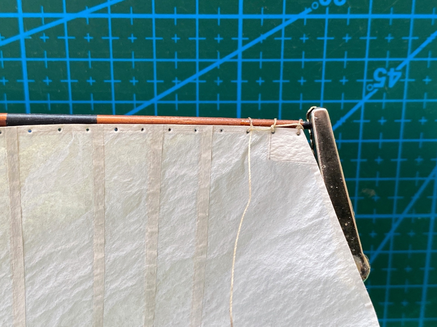
Fore Topsail is seized to the steel jackstay of the Fore Topyard.
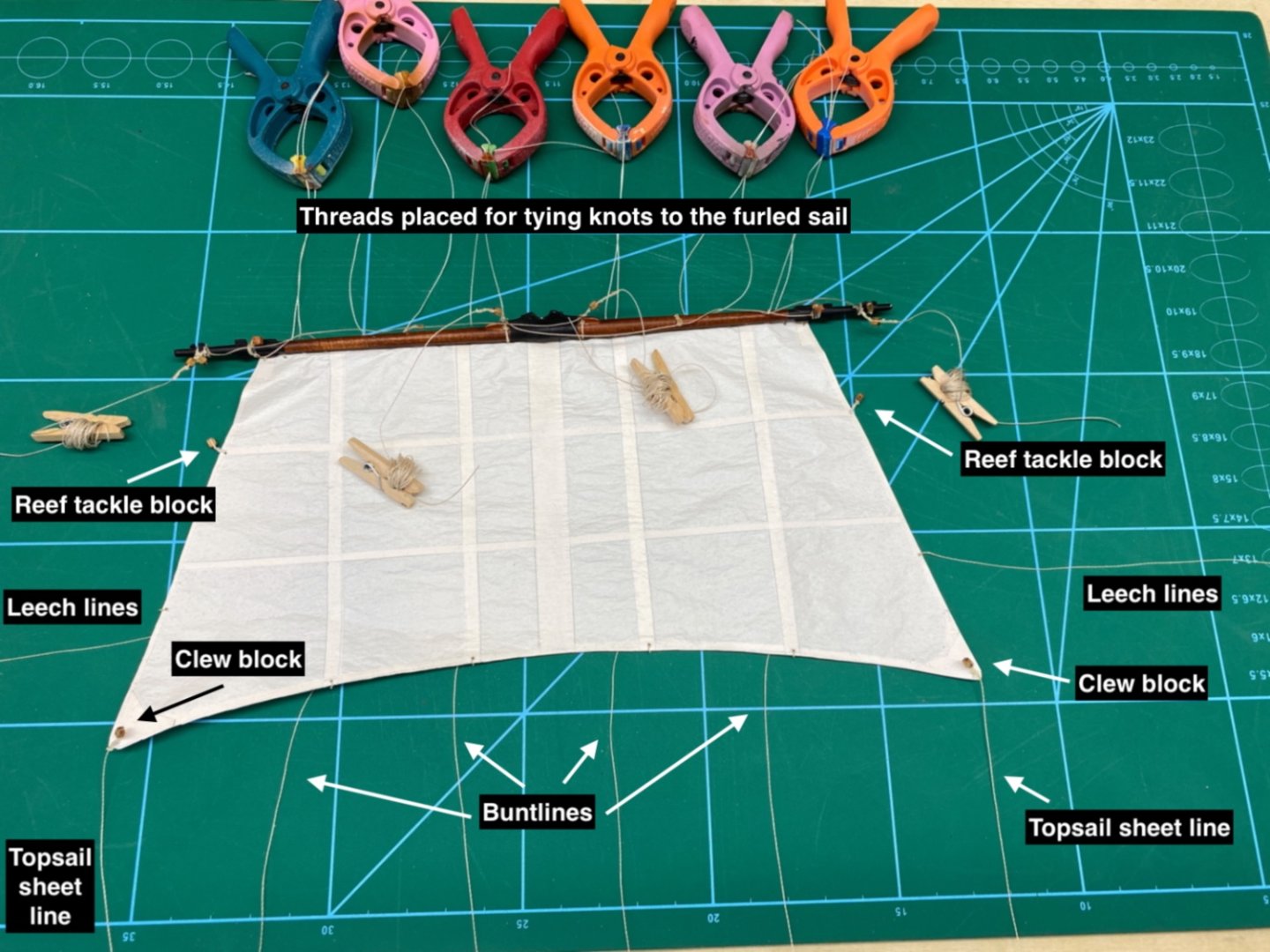
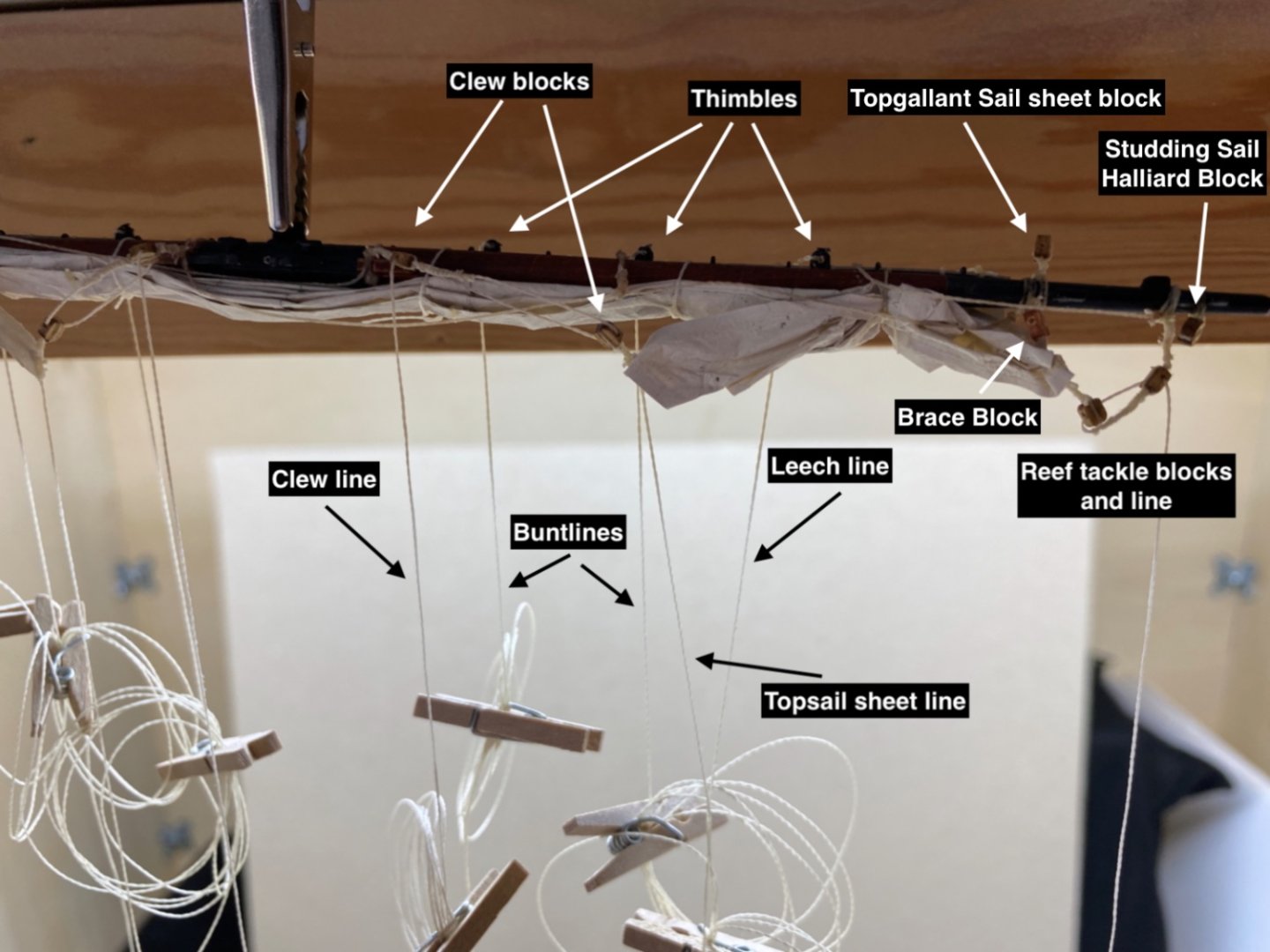
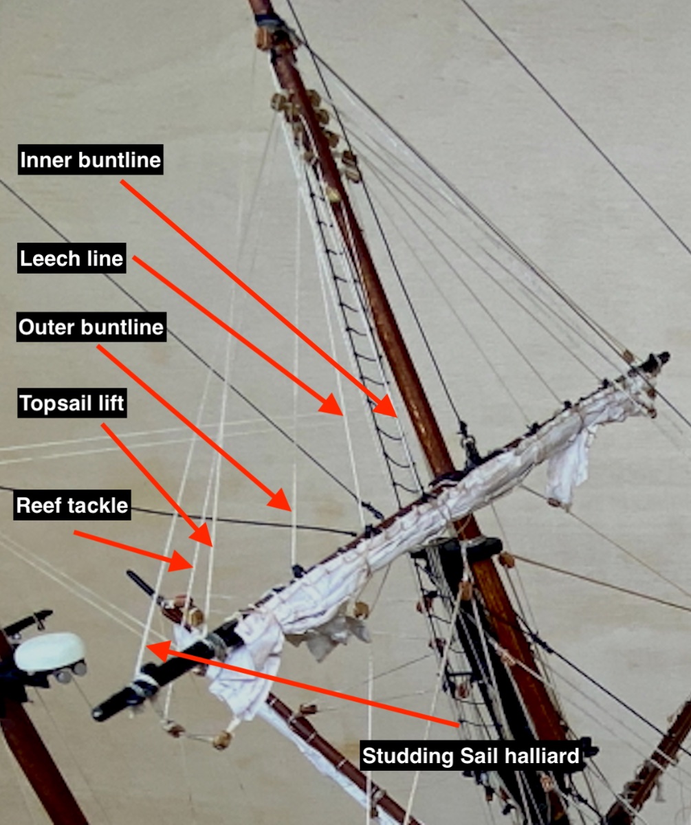
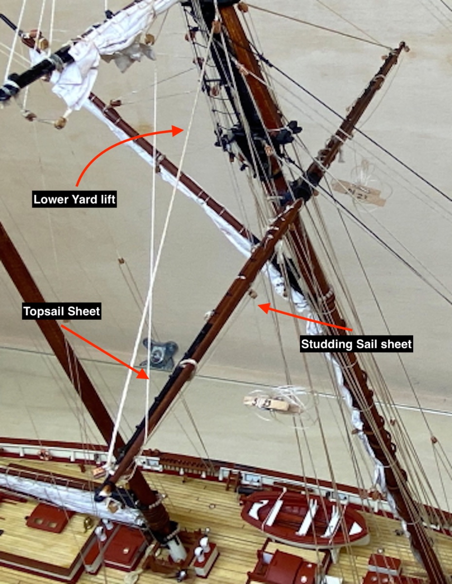
In the below photo you see the Fore Topsail laid between the Fore Lower Yard and Fore Top Yard. Several blocks rigged to yards can also be seen. Here is the legend for those blocks.
Red arrows Top yard and Lower Yard brace blocks
White arrows Clew line blocks with lines
Yellow arrows Reef tackle blocks with lines
Green arrows Topsail sheet blocks
Orange arrows Studding Sail sheet blocks
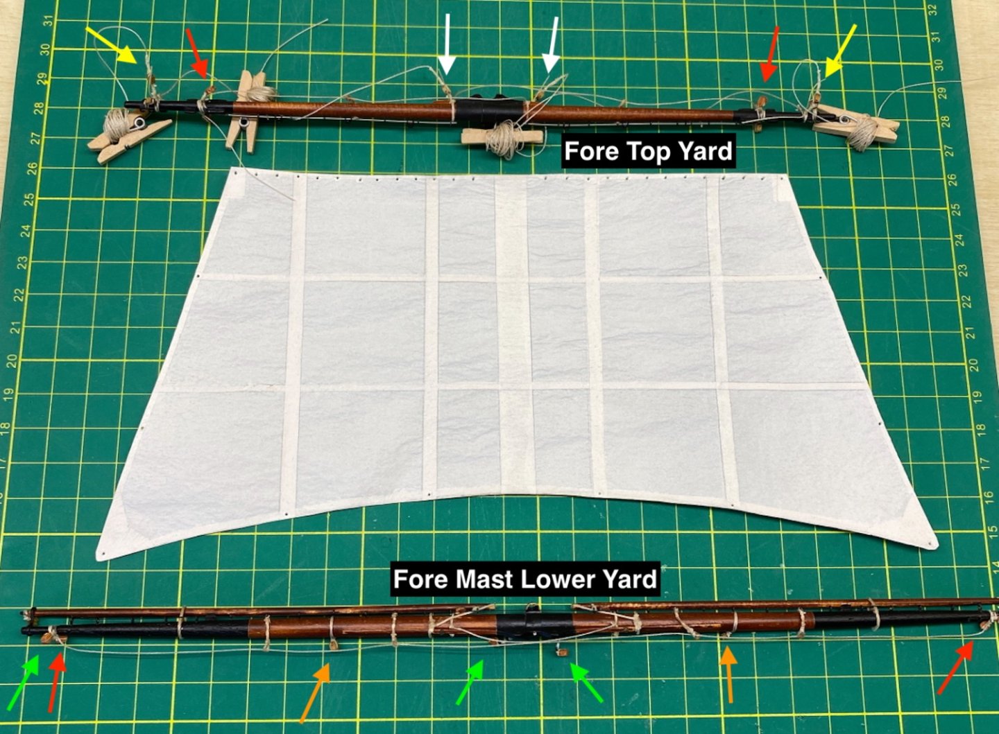
Here is a photo of the Fore Topsail after it was seized to the steel jackstay of the Fore Topyard. You can also see the holes opened for seizing buntlines, leech lines, Topsail sheet lines , reef tackle blocks and clew line blocks. Here is the legend for those holes
Red arrows Buntlines
Black arrows Leech lines
White arrows Reef Tackle blocks
Yellow arrows Clew blocks and Topsail sheet lines
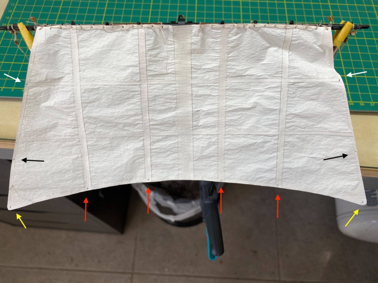
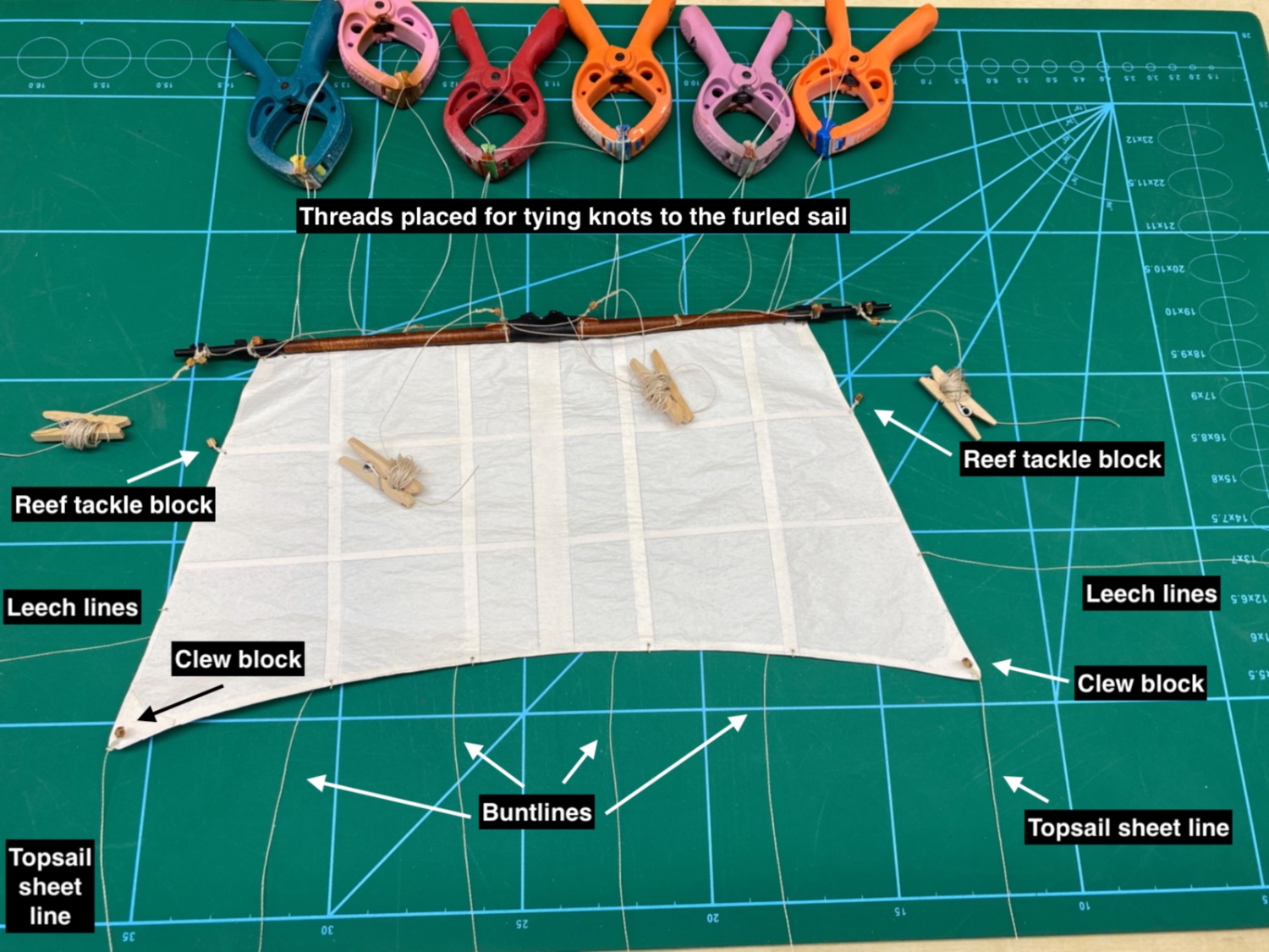
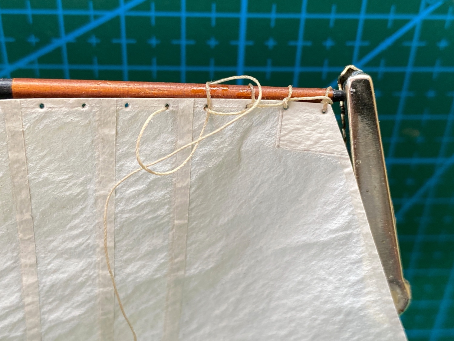
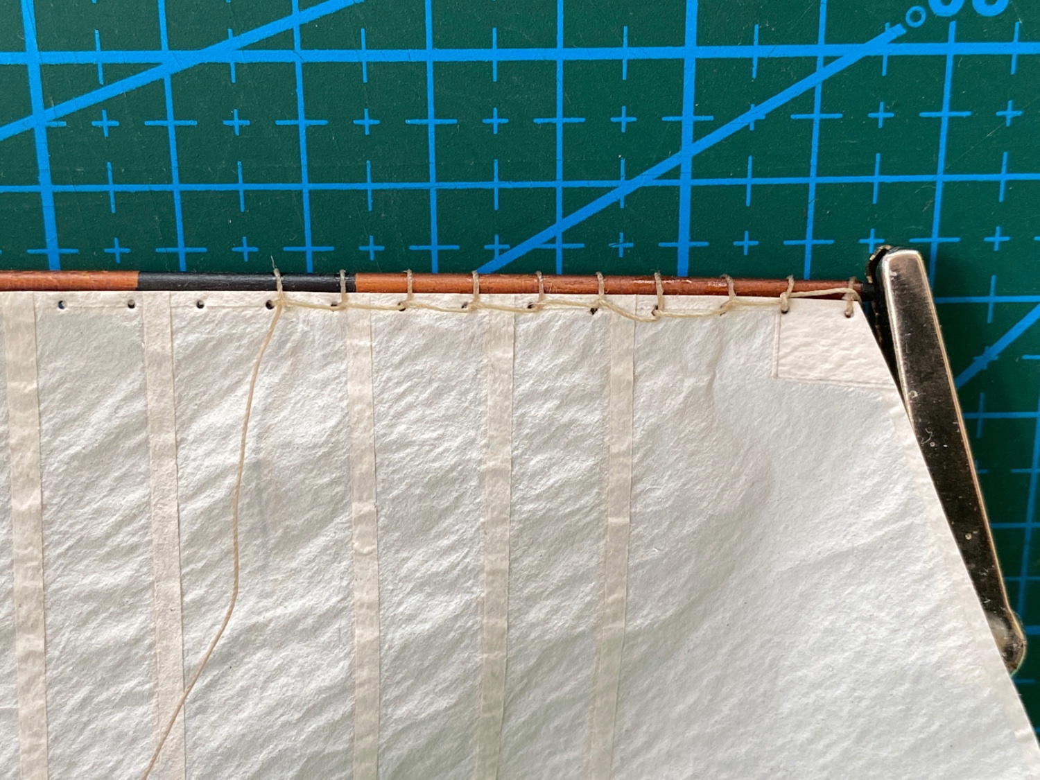
Here in the photo below all the rigging lines and blocks seized to the sail can be seen. Also the threads for tying knots after the sail was furled, were placed to the yard.
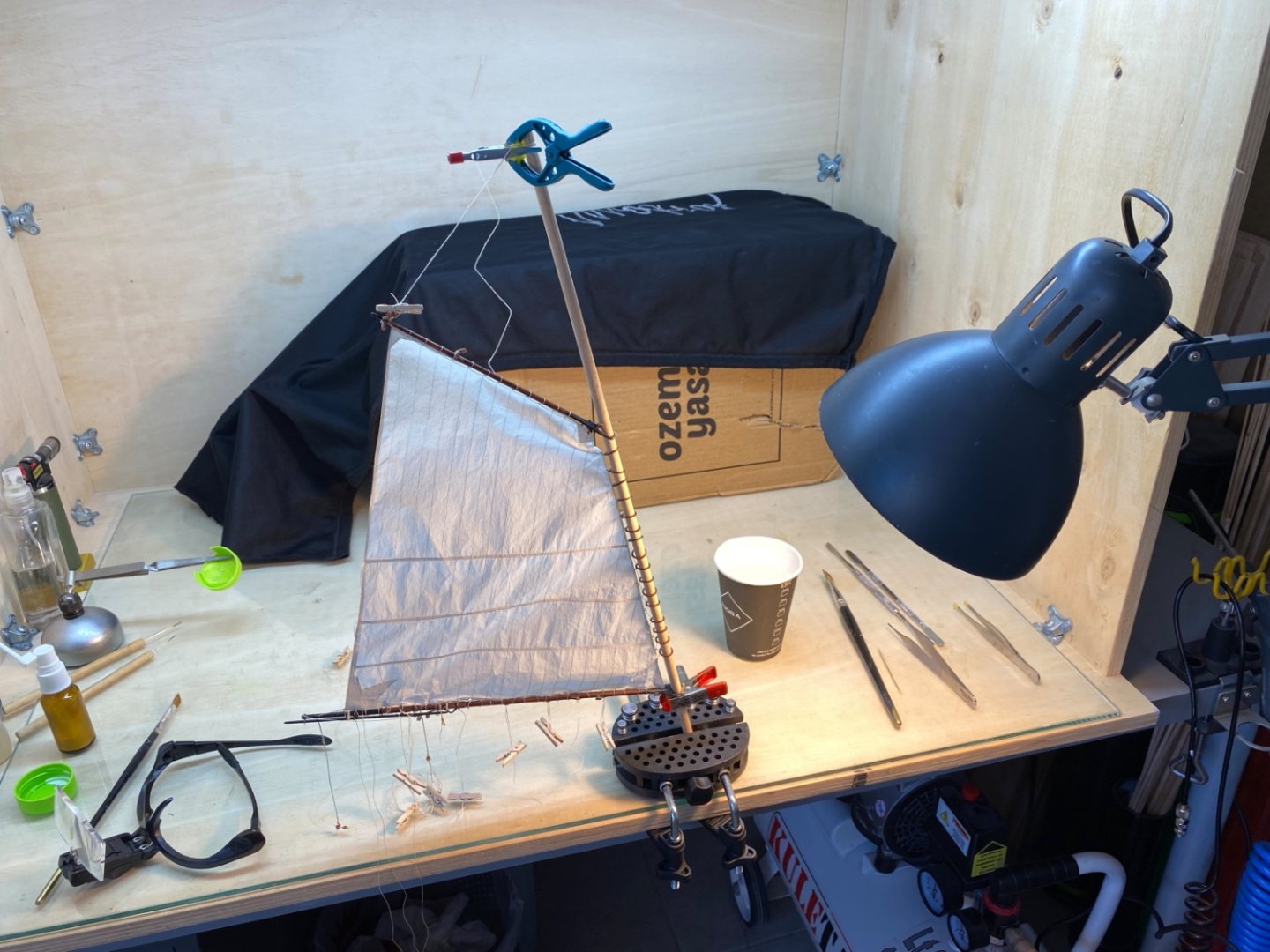
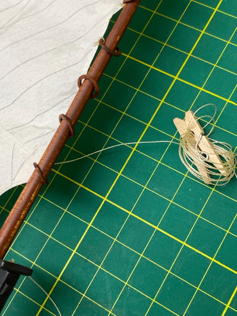
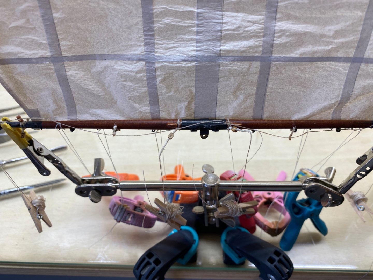
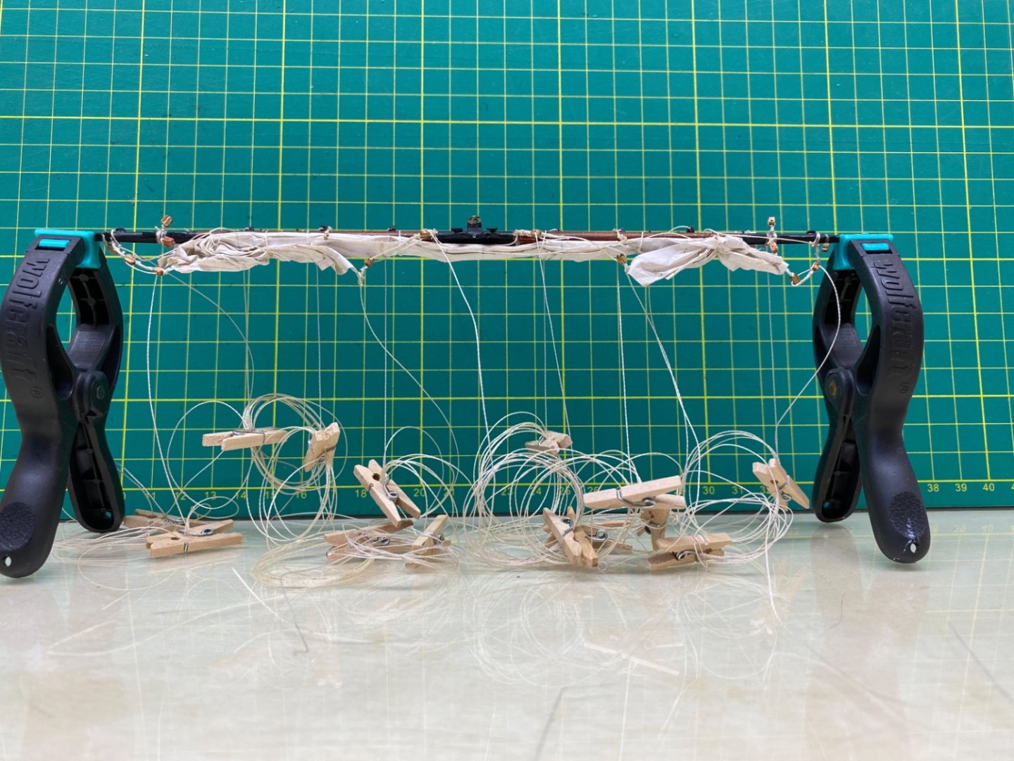
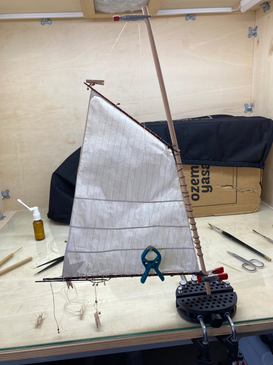
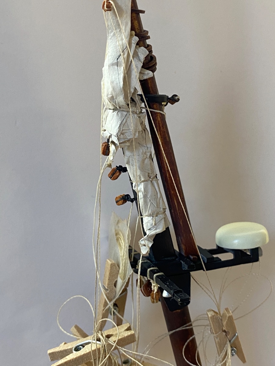
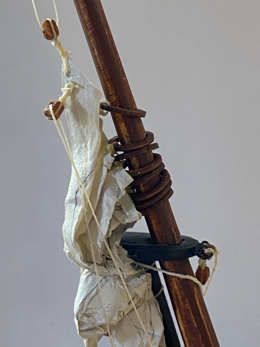
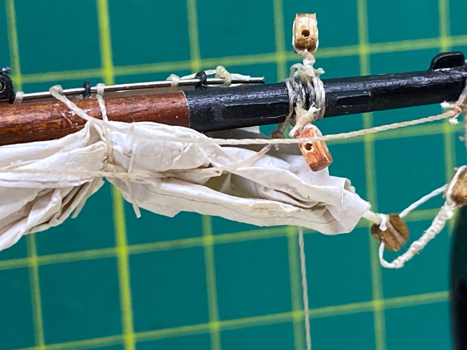
Here you can see the setup for the furling of the topsail. The sail was fixed in reverse position (Upside yard down and downside of the sail up) with two arm holder fixing the yard and the Topsail sheet lines fixed above holding the sail upwards.
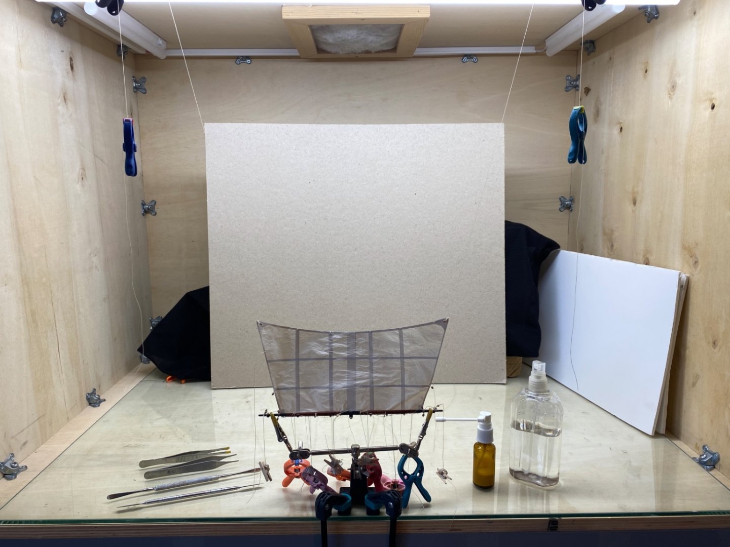
Water in a spray bottle and diluted white glue in a smaller spray bottle. Diluted white glue was later applied by a dry cut brush however as the flow of the diluted white glue was uncontrollable from the small spray bottle.
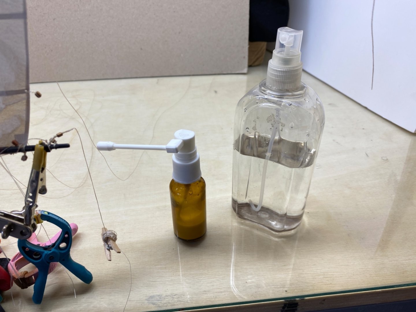
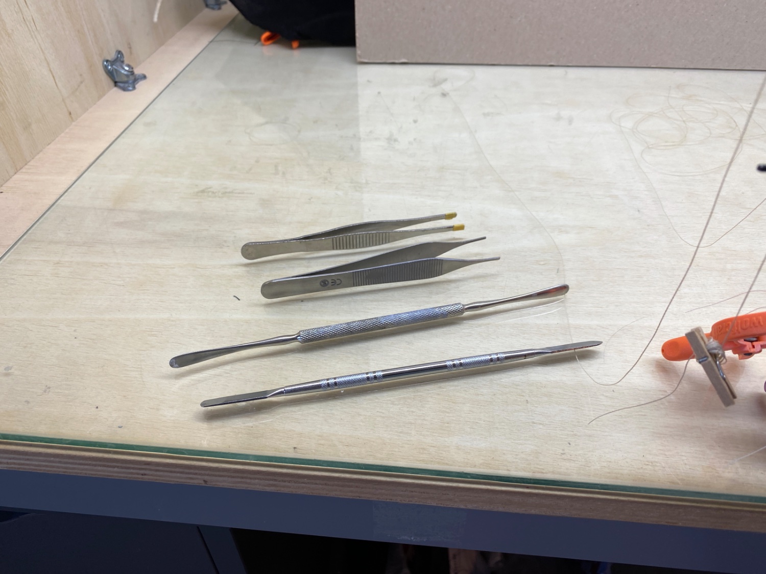
Blunt tip tweezers and instruments were used in order not to damage the sail accidentally .
Close up photo of the placed threads for tying knots later.
As this was my first experience with sail furling I was a bit nervous and excited. Naturally I forgot to take photos during the furling process.
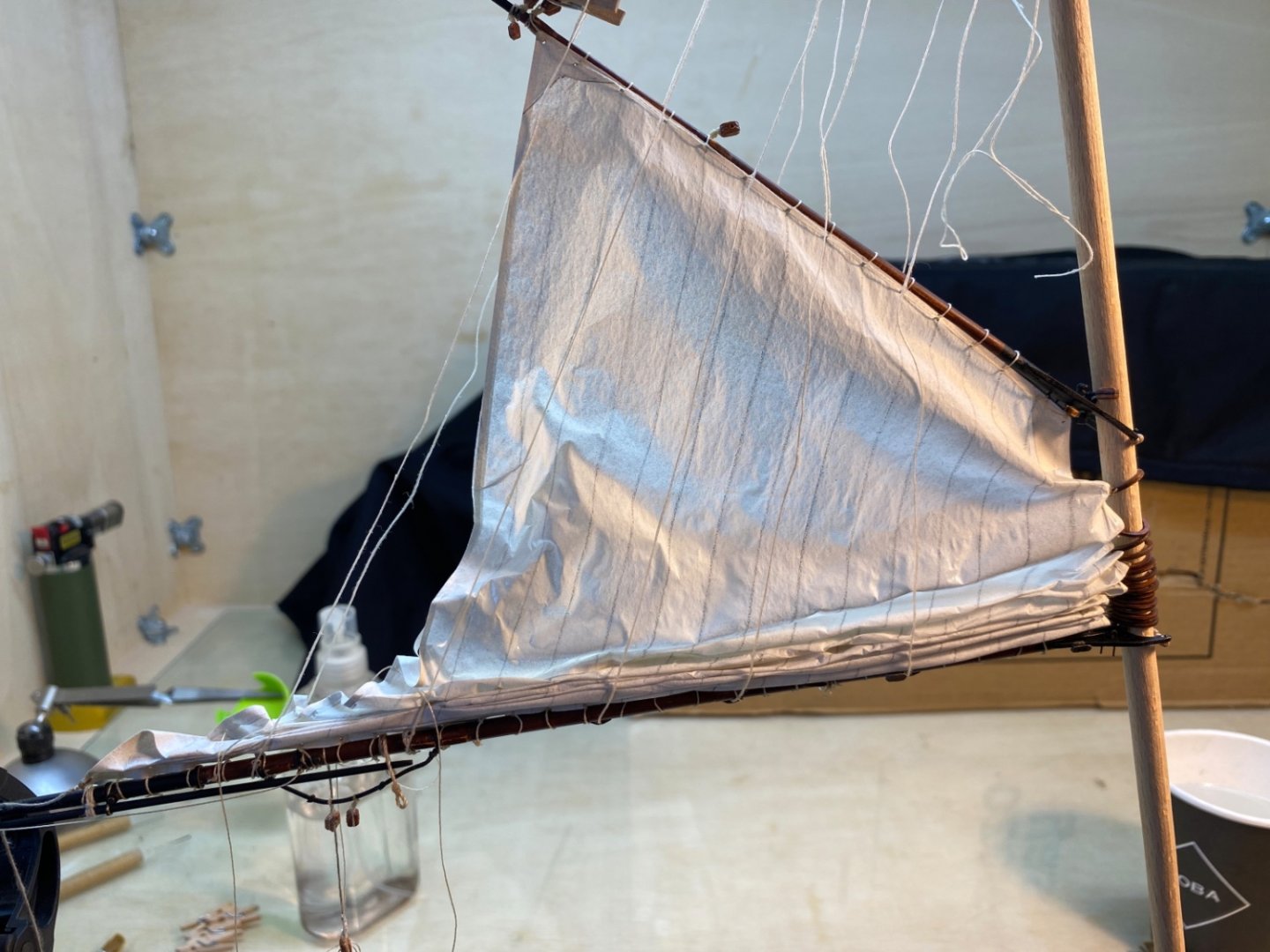
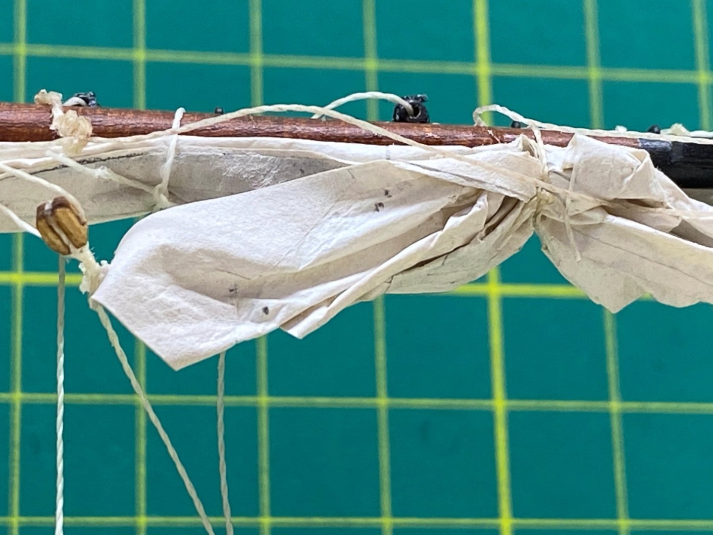
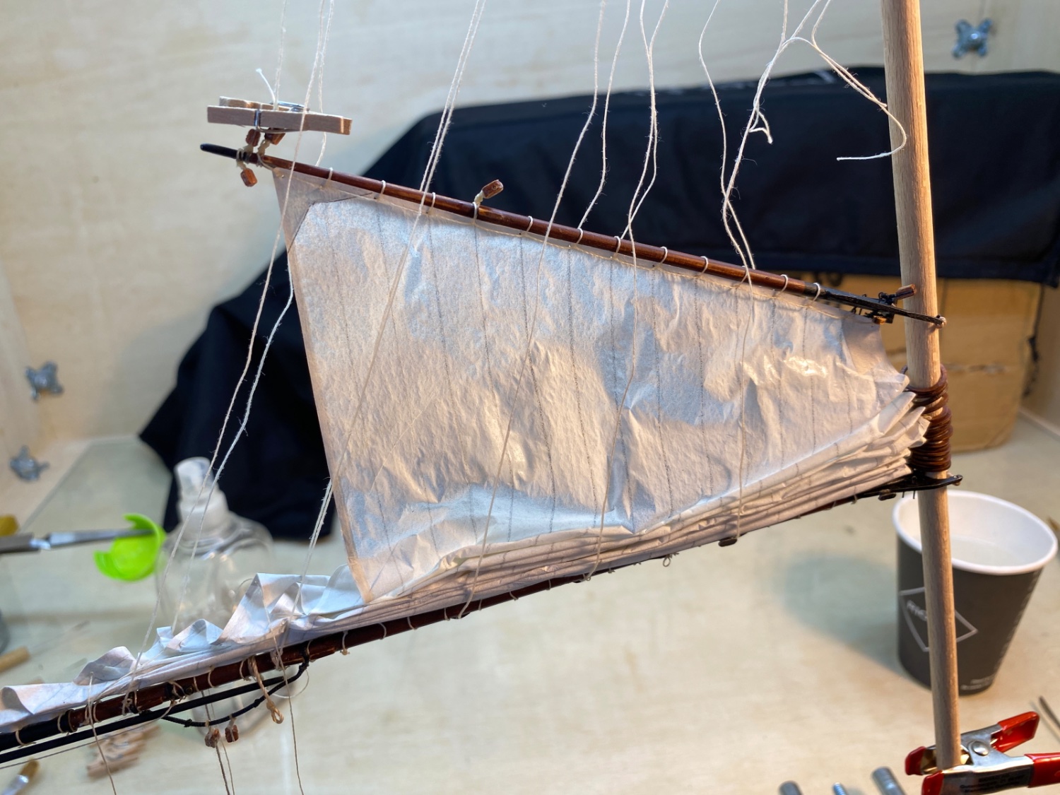
I started to wet the sail from the already seized side. Holding the sail with tweezers and folding it with the elevators and at the same time slowly releasing the tension on the holding sheet lines, I continued towards the free edge of the sail. After all the sail was folded and furled on the yard all the buntlines and leech lines were reeved through the metal thimbles previously attached to the steel jackstay of the yards. At the same step reef tackle lines and clew lines were also reeved through the related blocks. Previously placed threads were used to tie knots to fix the furled sail.

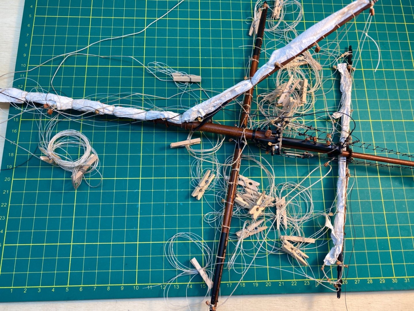
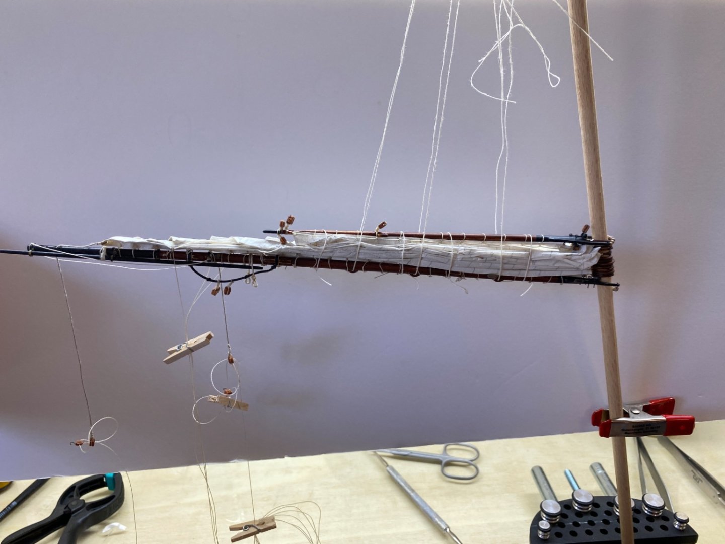
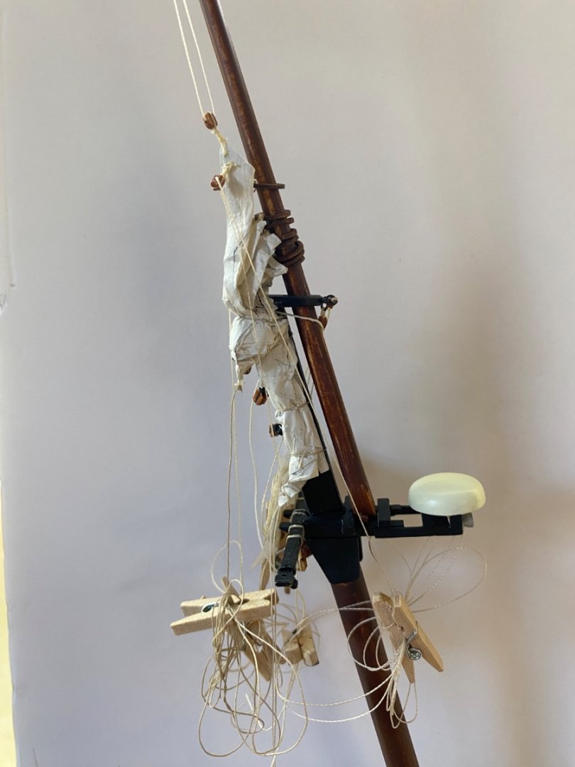
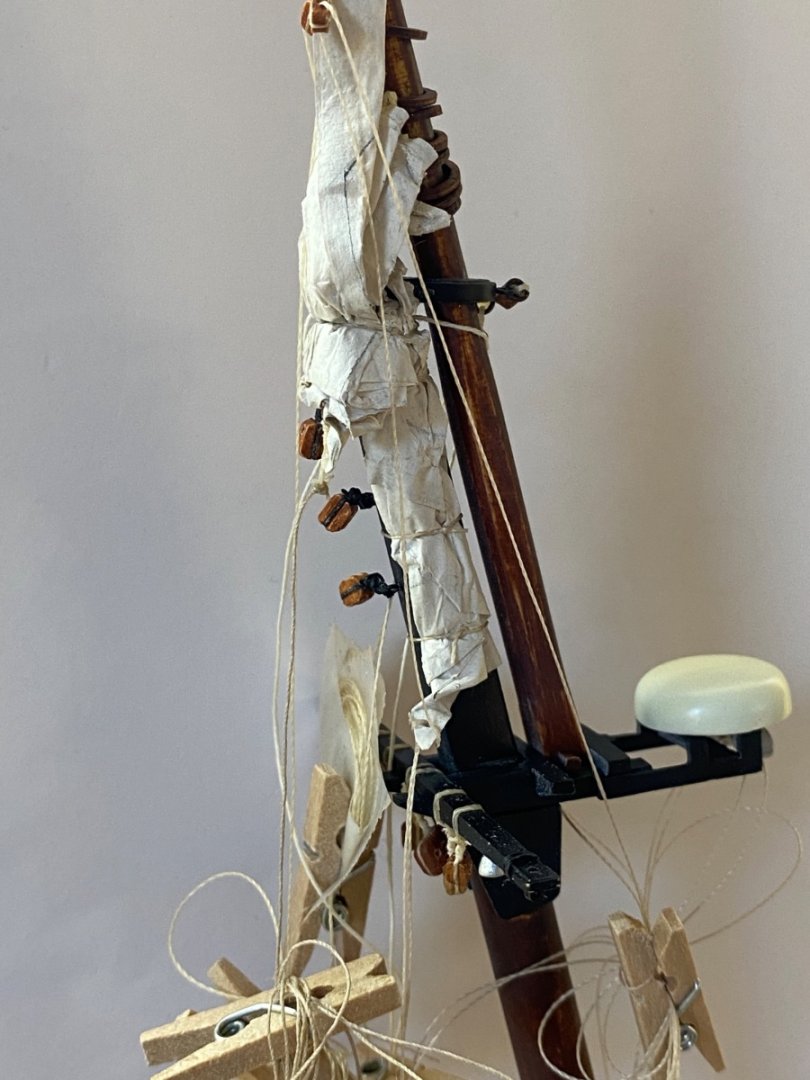
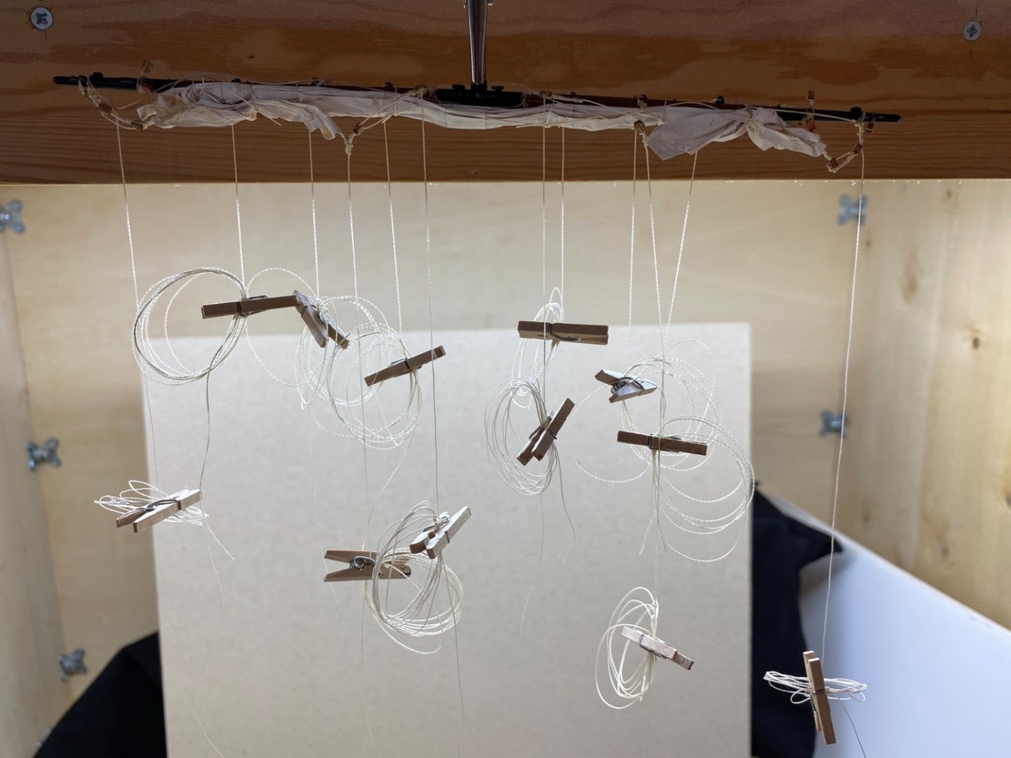
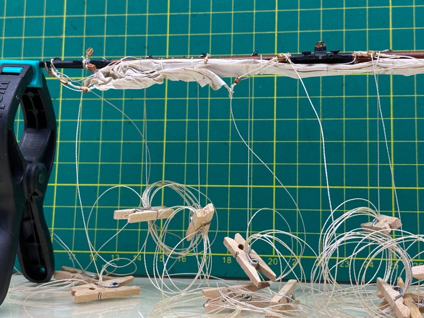
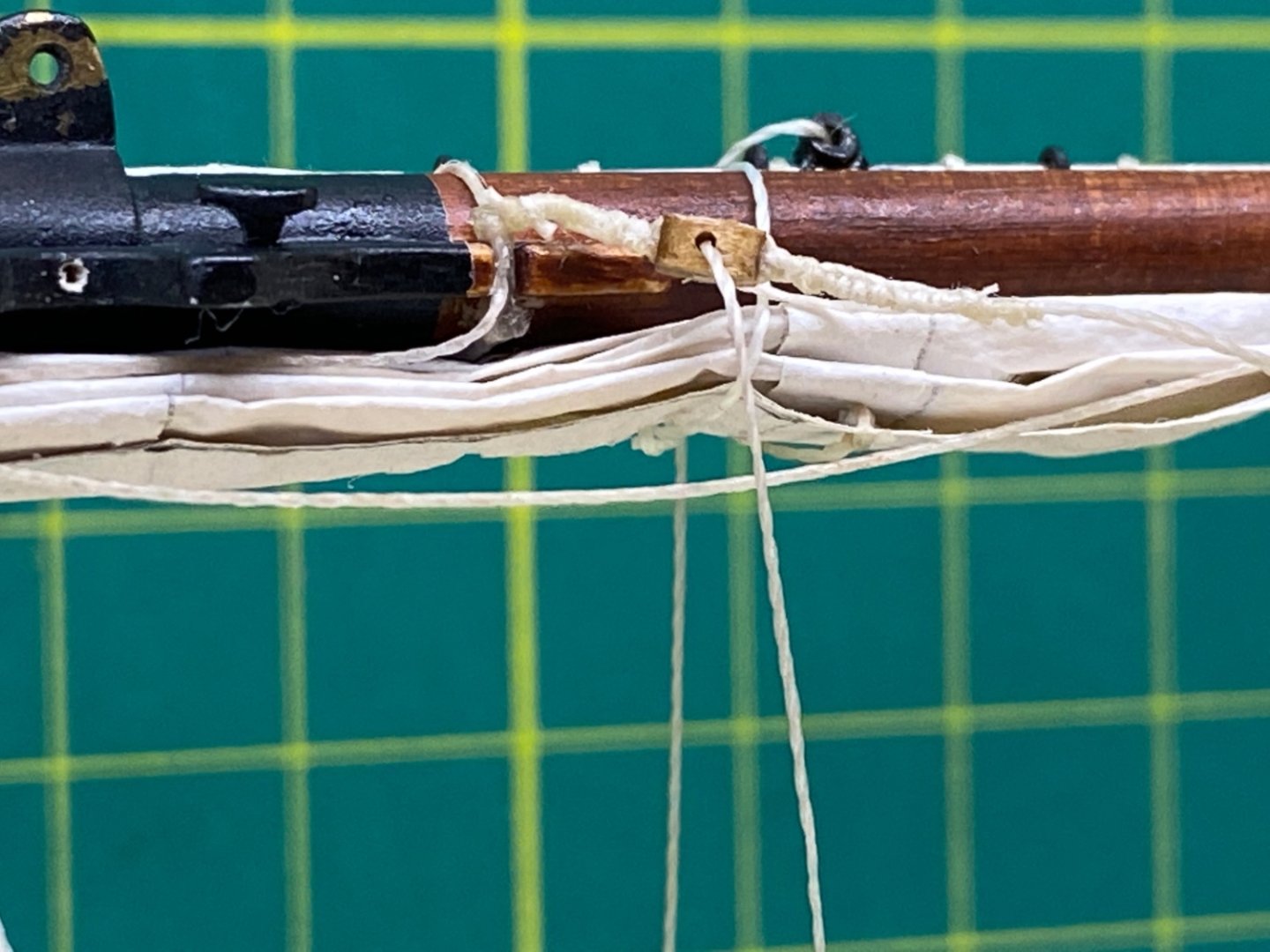
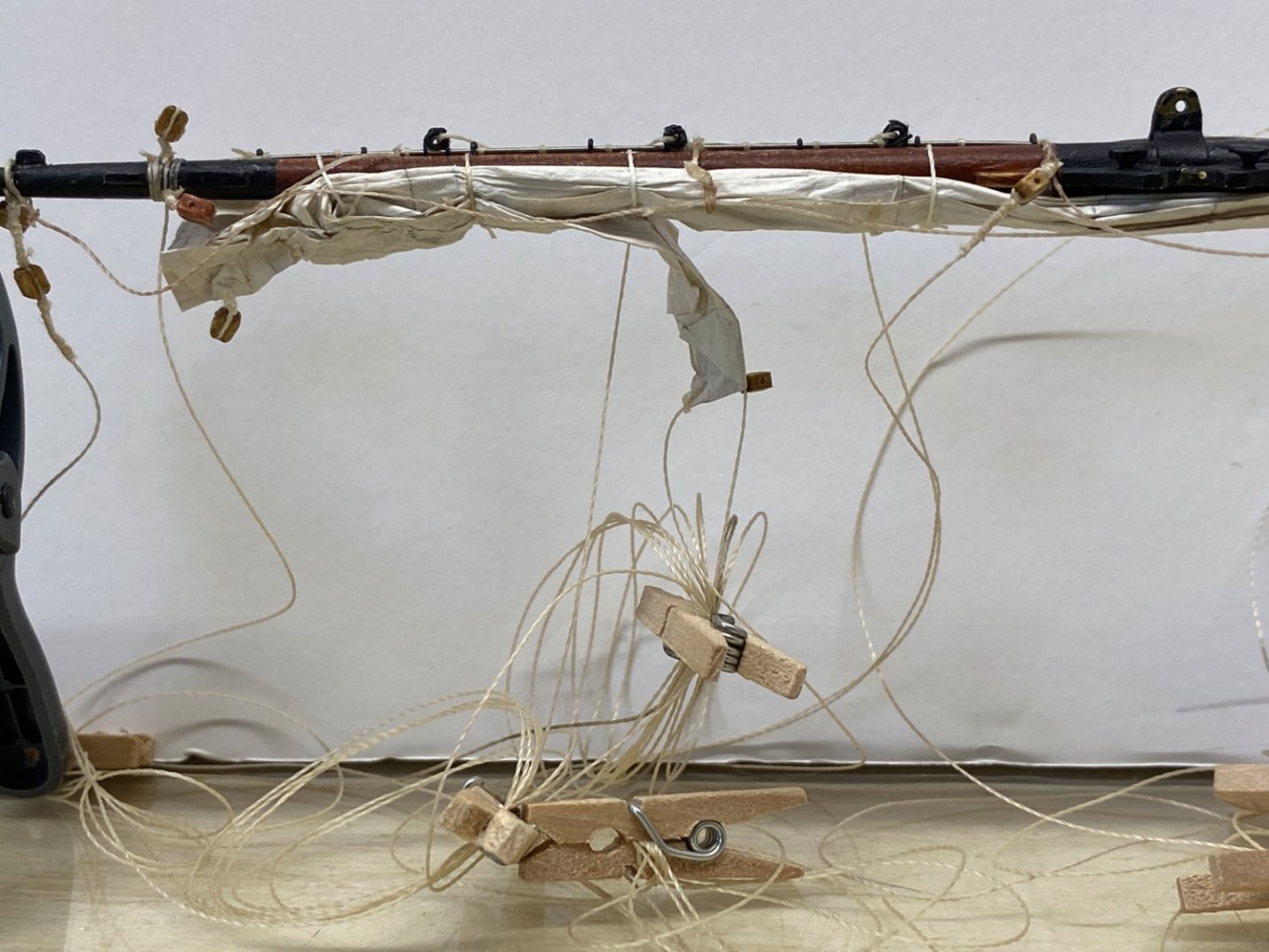
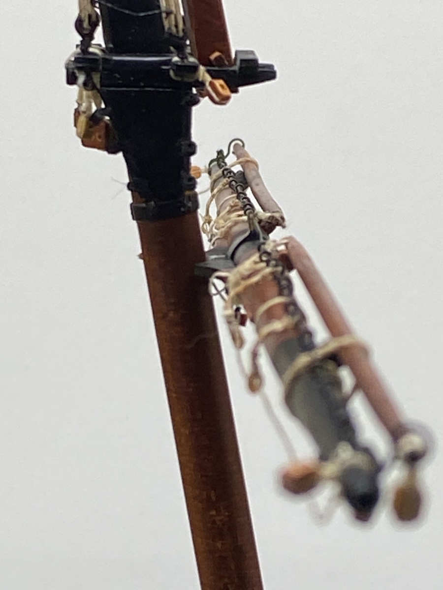
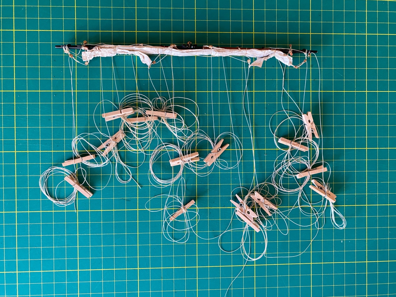
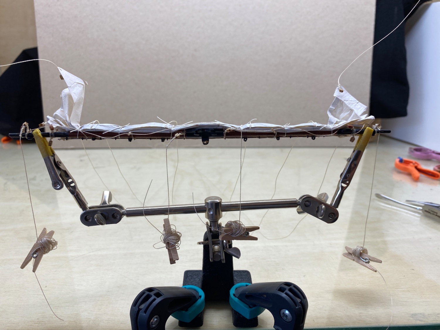
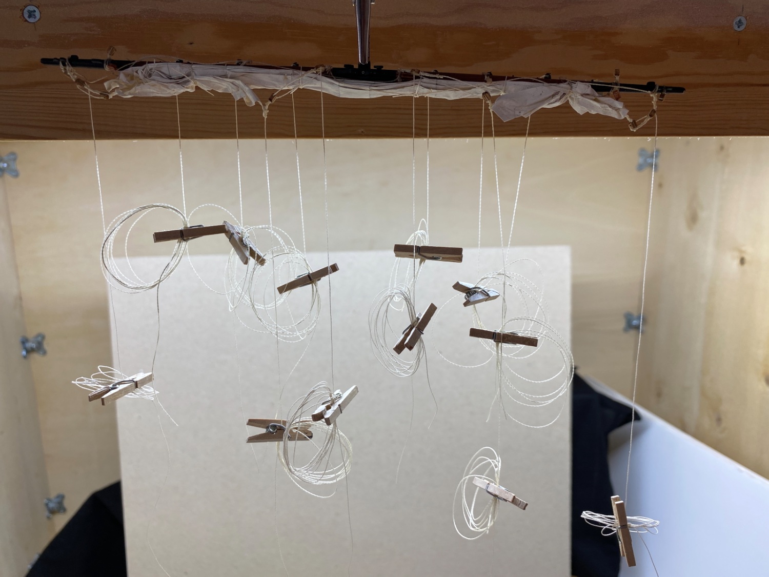
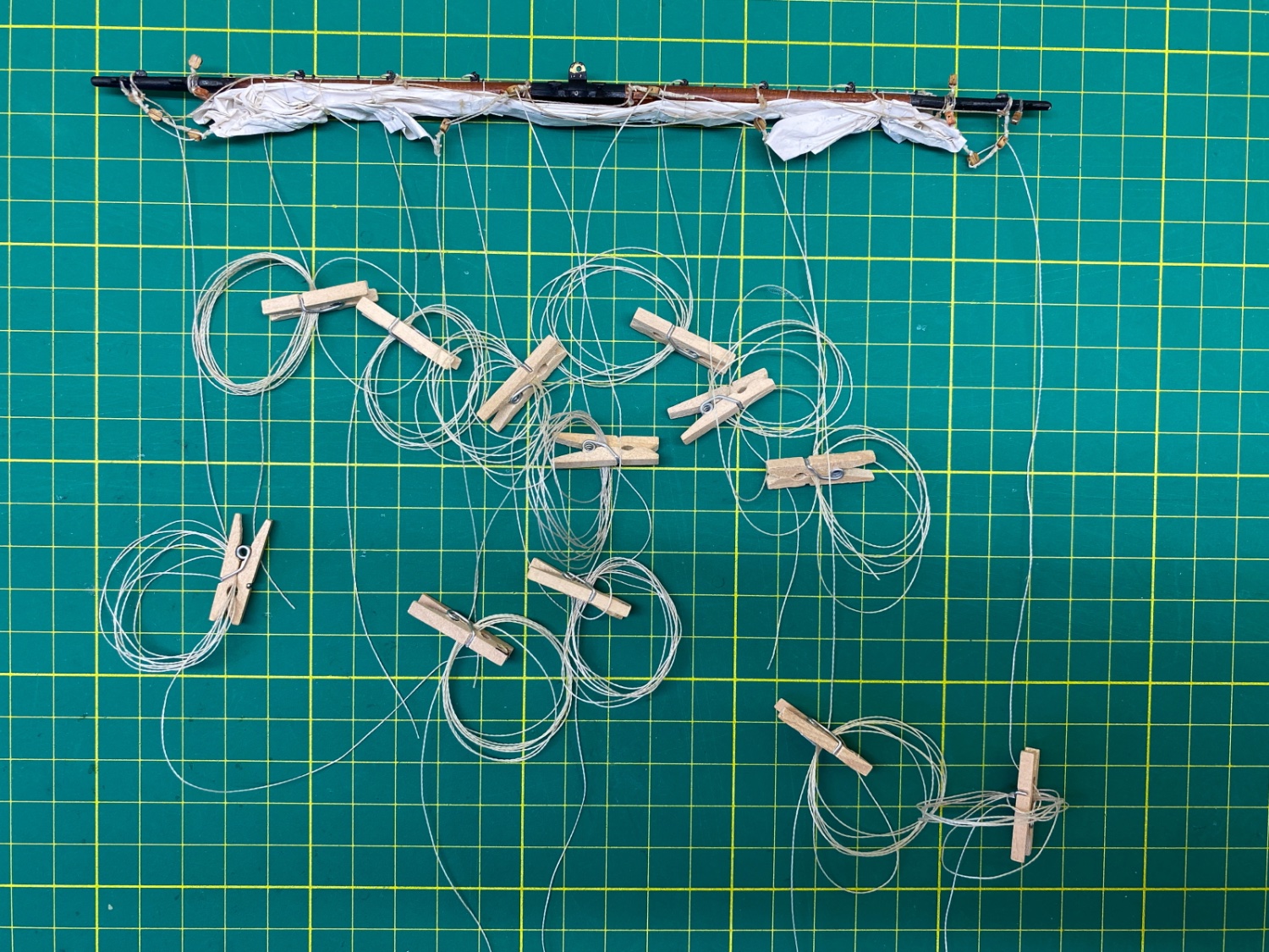
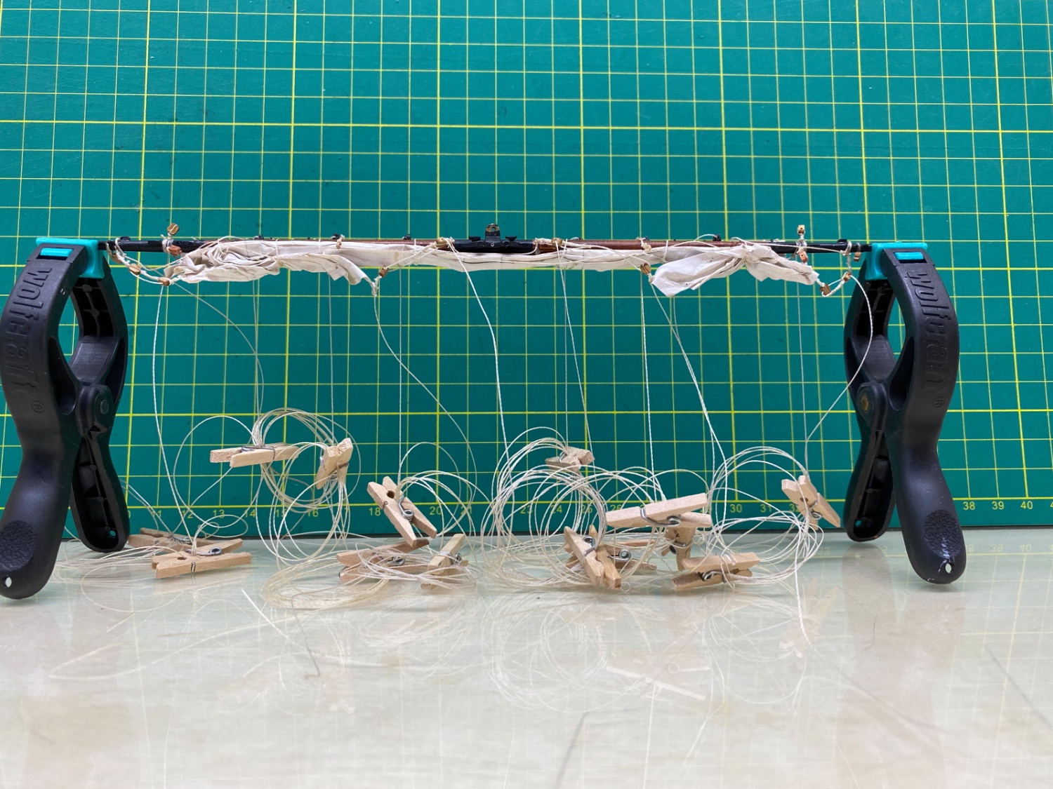
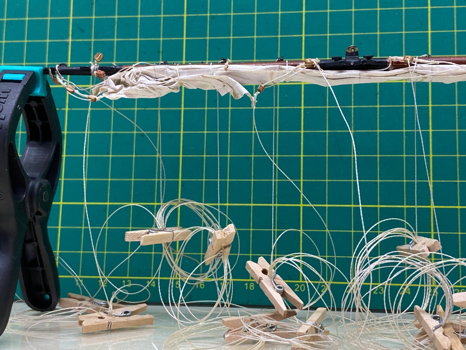
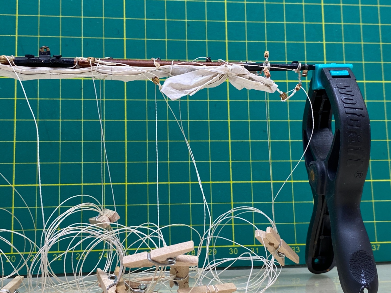
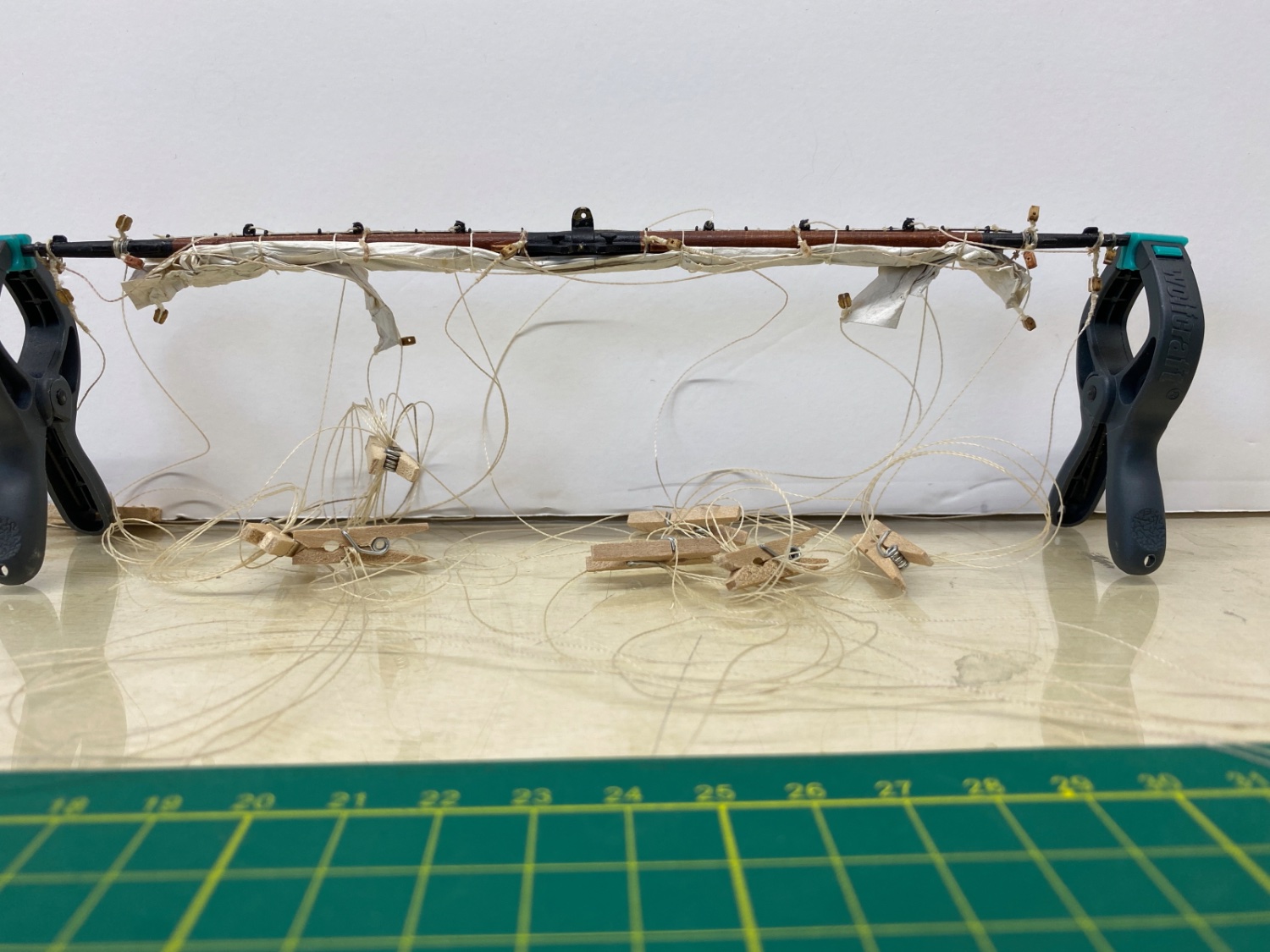
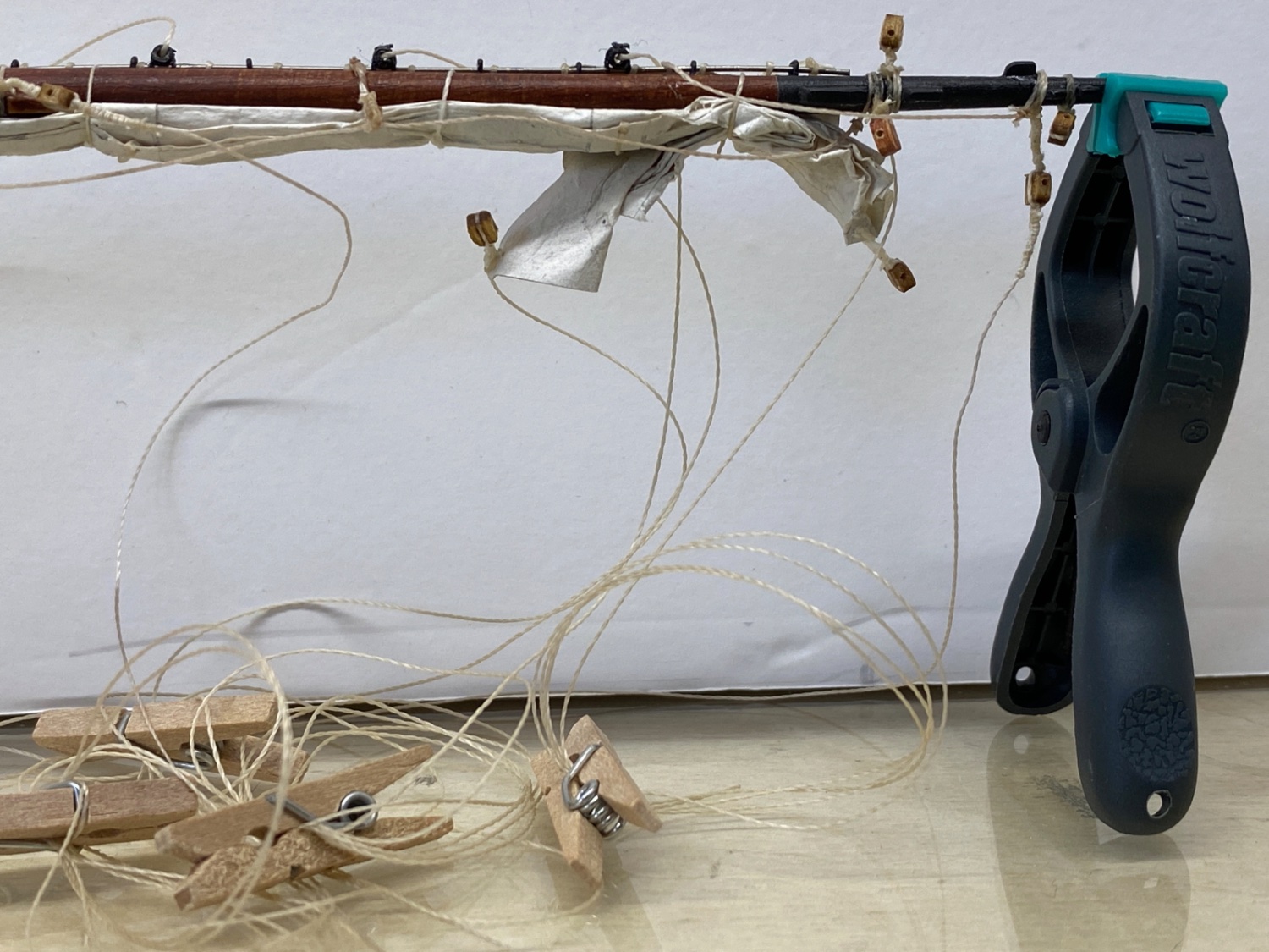
The yard was then removed from the two arm holder and fixed hanging in the natural position ( Yard up and sail down) Here you can see all the rigging lines reeved through the their relevant blocks , coiled and clamped with mini clothing pins.
Here is a photo to several lines and blocks.
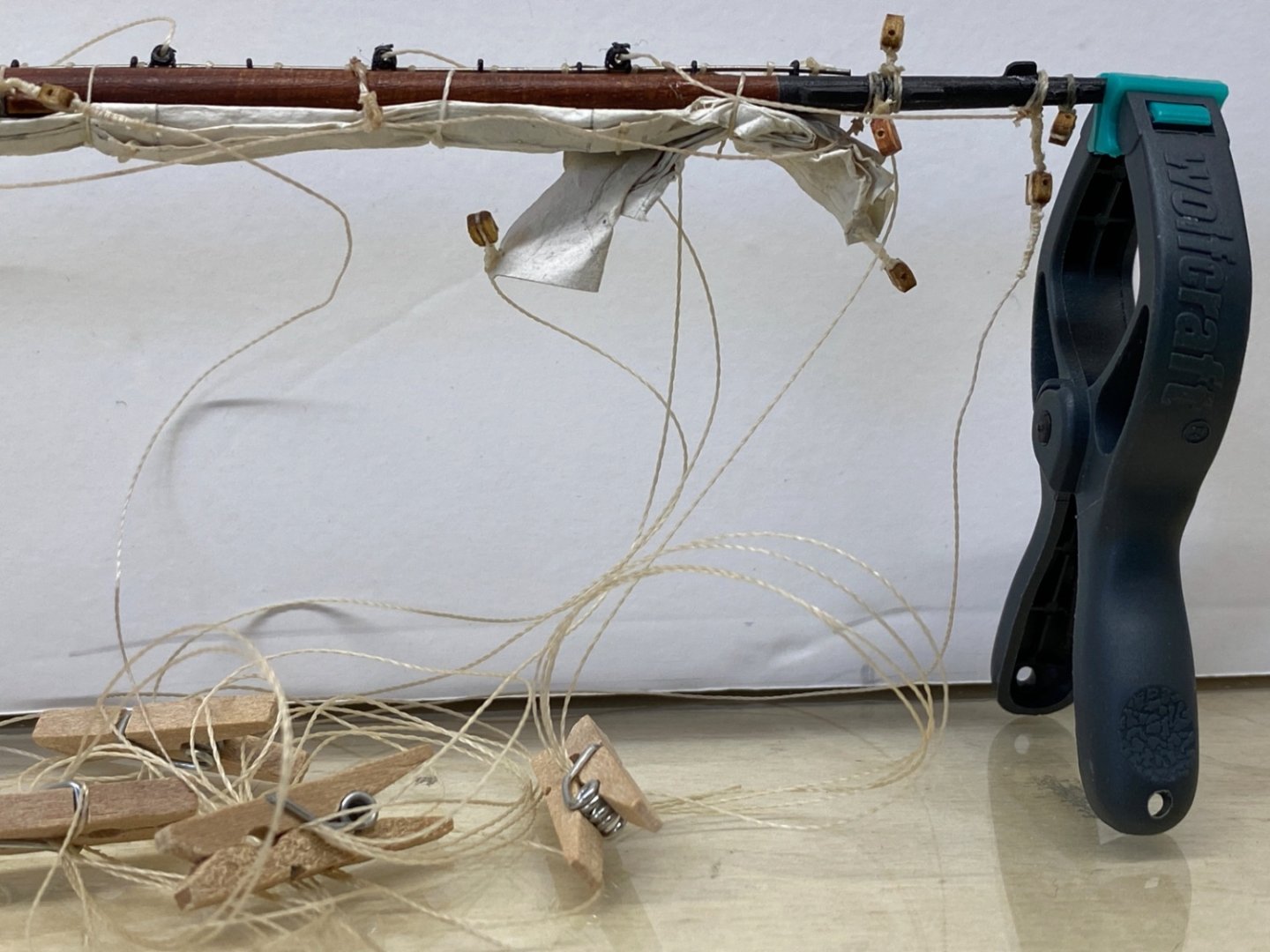
Here is a photo of the Topsail and Topyard system laid on cutting mat. It seems a bit chaotic but it was an organized chaos .

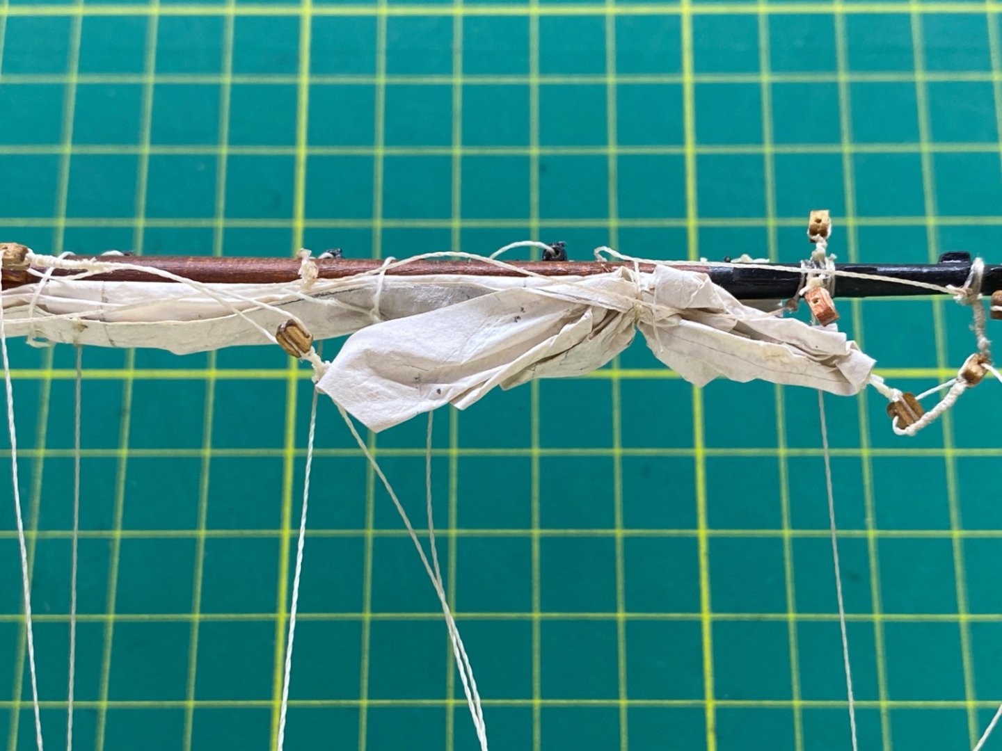
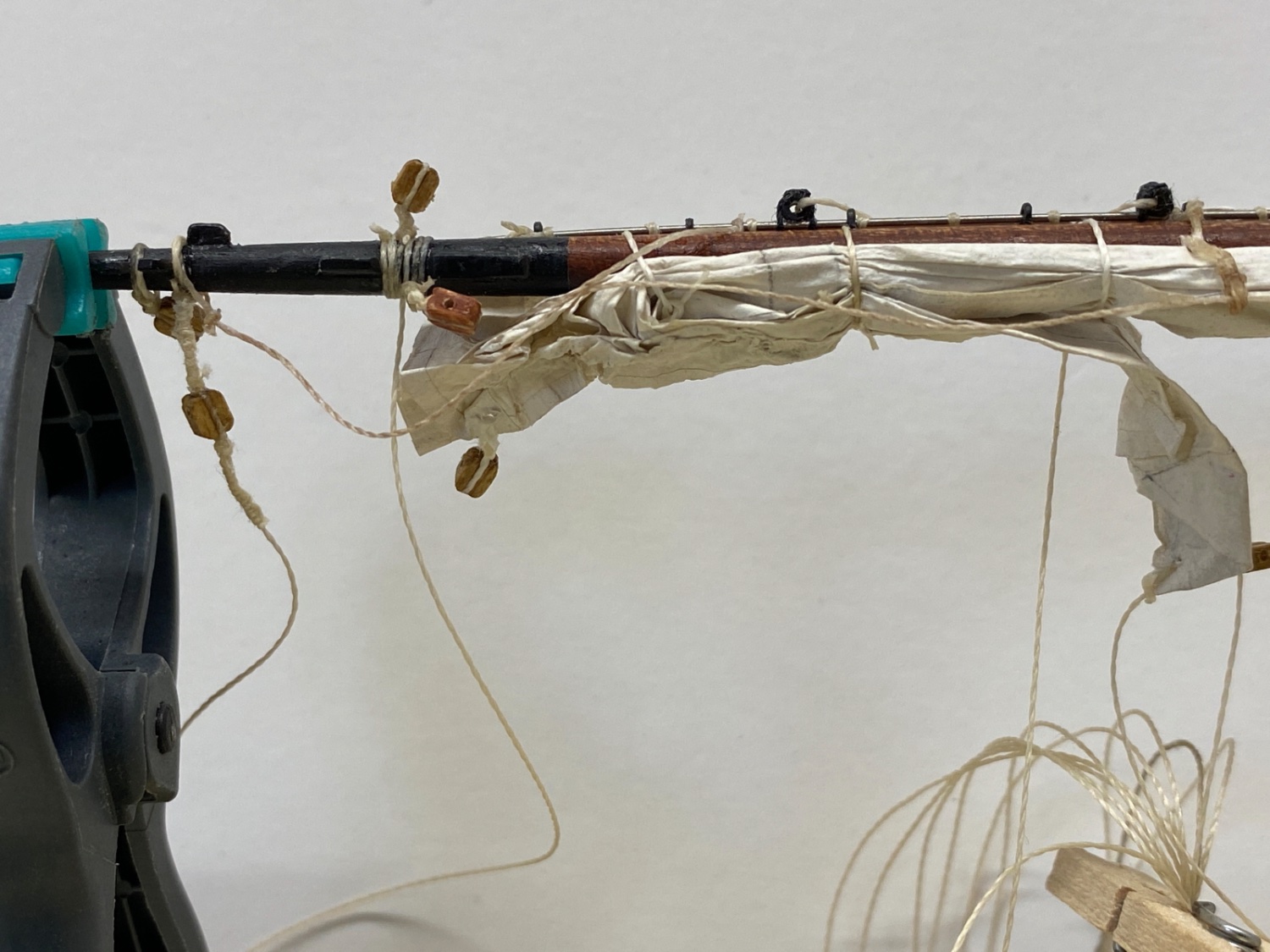
Here are some photos of the sail fixed in normal position and looking from aft to fore.

Closeup photos
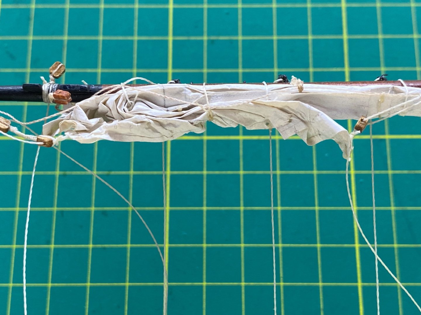


Sometime in the later steps I decided to reshape the clew tips of the sail. After wetting the part of the sail to be shaped again with water, I carefully unfold the sail with suitable tweezers and elevators and reshaped it. In the final desired position diluted white glue was applied by a cut brush. Here are photos. You can easily see the unreeved (I hope the term is correct) clew line and reef tackle blocks.


So the first proper sail was seized to yard and furled.
- Knocklouder, Prowler901 and yvesvidal
-
3
-
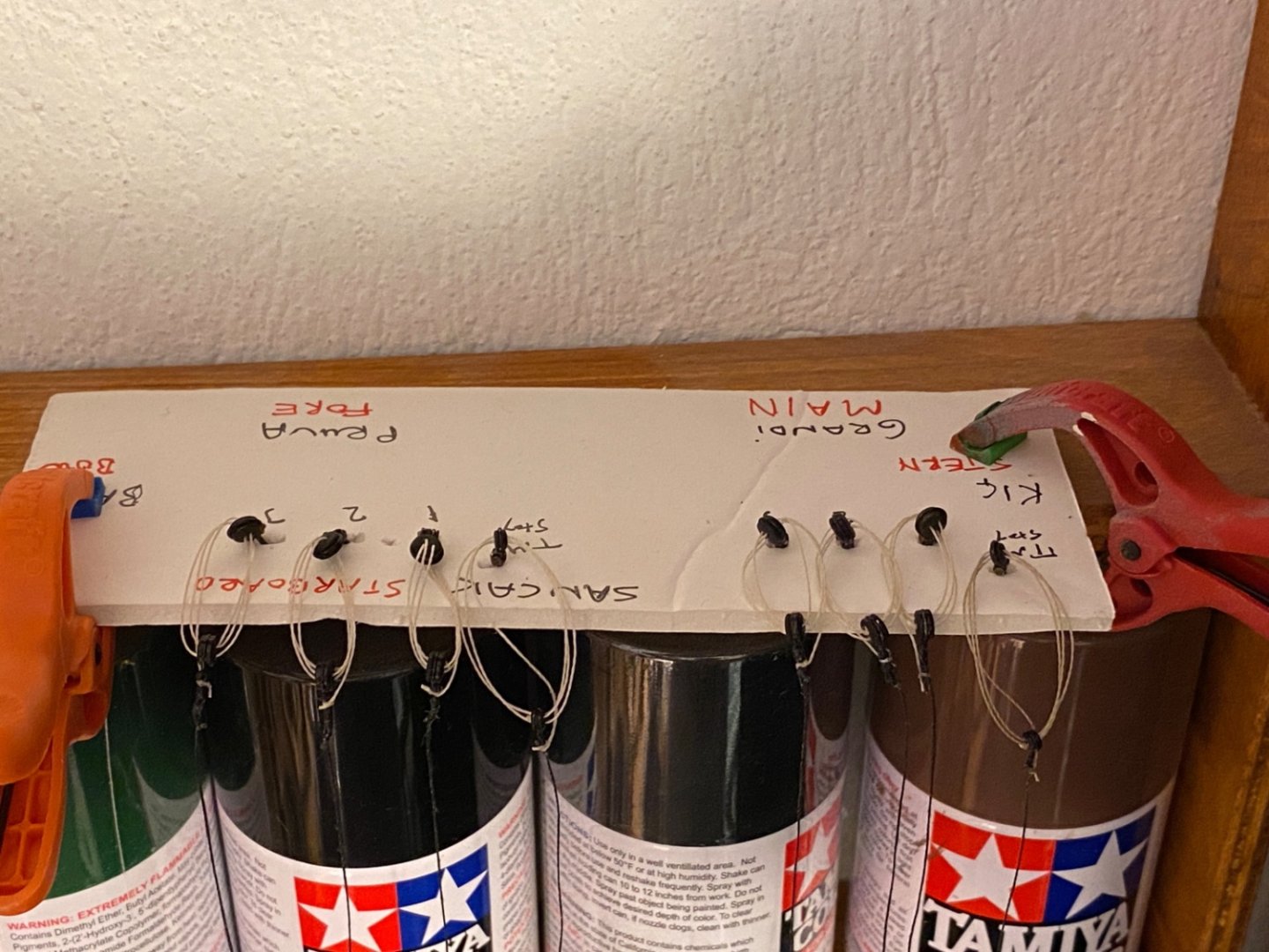
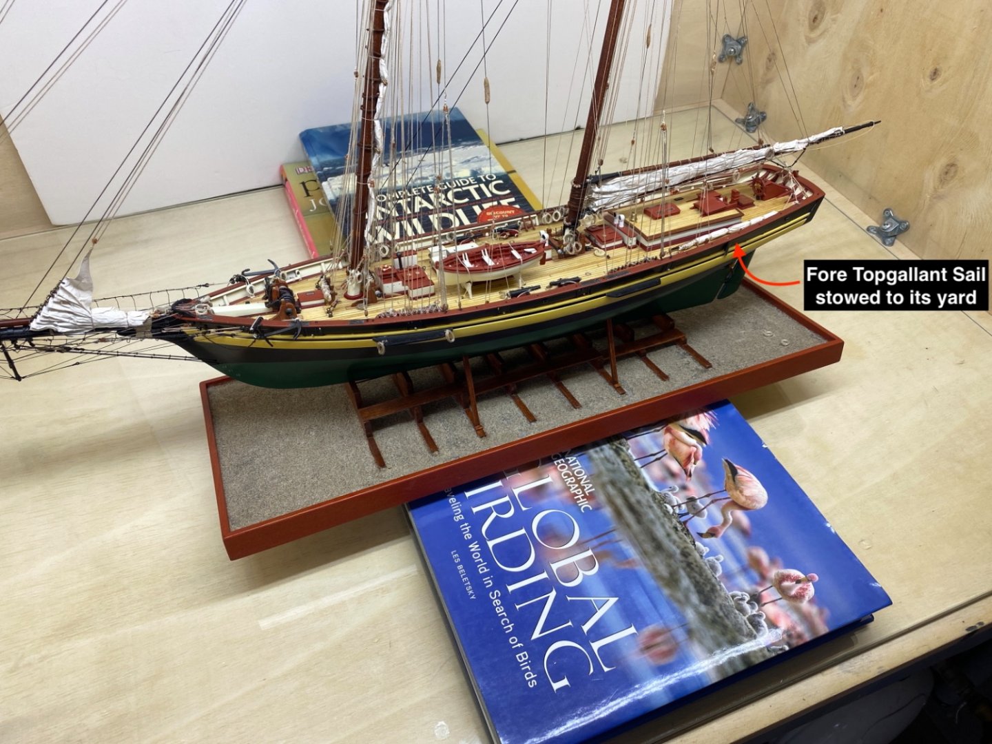
I started to seizing the sails with the smallest one, Fore Topgallant Sail. The rigging for this sail was omitted as it was stowed at port aft bulwarks after it was seized to its yard and furled.
First holes for the seizing line were opened by a pin. Those holes were later strengthened with touches of liquid CA glue.Then its yard was fixed in a two arm holder with alligator clips. A continuous tan colored stitching was used for seizing . At the beginning and ending knots a touch of CA glue was applied. The seized sail was stored and protected until final installation.


- Prowler901, yvesvidal and Knocklouder
-
3
-
On 1/13/2023 at 9:07 PM, halituzun said:
I like to inform you and future viewers about the index list I started to record in Post #1.
Page number/ Post number/Post subject are given in ascending order of the post numbers.
I tried to link them to their exact position in the blog, but I could not do it. I’ll try again later.
I solved the linking problem and started linking the post page/number/post topic or topics . Clicking the underlined areas will take you directly to that post.
-
Yves,
Thanks a lot for your comment -
It is now September 19th, 2022 and 25th month of the build.
It was time to decide what to do with the 'sail issue'. I had zero experience with model ship sail making. At first I tried several kinds of cloth, including silk, but couldn't get an acceptable result. The most challenging job was getting hem and seams properly with sewing machines. I even asked professional tailor shops at that time. 1:64 scale was the biggest obstacle and I decided it would be very hard if not impossible for me, to prepare in scale sails by using cloth.
While surfing the internet for sail making solutions , I came across the term 'Silkspan' and lot of ship models where it was used to make sails. Ship modeler Tom Lauria posted two excellent videos on YouTube about using silkspan in sail making.
I also found other useful articles about the use of silkspan and other tissues in PDF format.Here are links
https://www.lauckstreetshipyard.com/post/2017/05/12/making-silkspan-sails
https://freeflight.org/Library/TechLibrary/TissueIssues.pdf
http://www.flyrc.com/silkspan-blast-past-new-twists/
A quick search on the internet resulted in the limited availability of the silkspan throughout the world. However the other kind of special tissue from Japan , Esaki paper , can be found easily. Esaki paper is essentially similar to silkspan also having plant origin fibers, but its wet strength is weaker.
I found Esaki paper from a local aviation model supplier and decided to use it.
As the model will be on building ways , the sails must be furled or not used at all. A local modeler suggested an interesting idea : sails folded and put a side on the ground of the building ways as if they were piled up to be sent to repair shop or repaired and waiting to be seized to spars.
I decided to go with the furled sails.
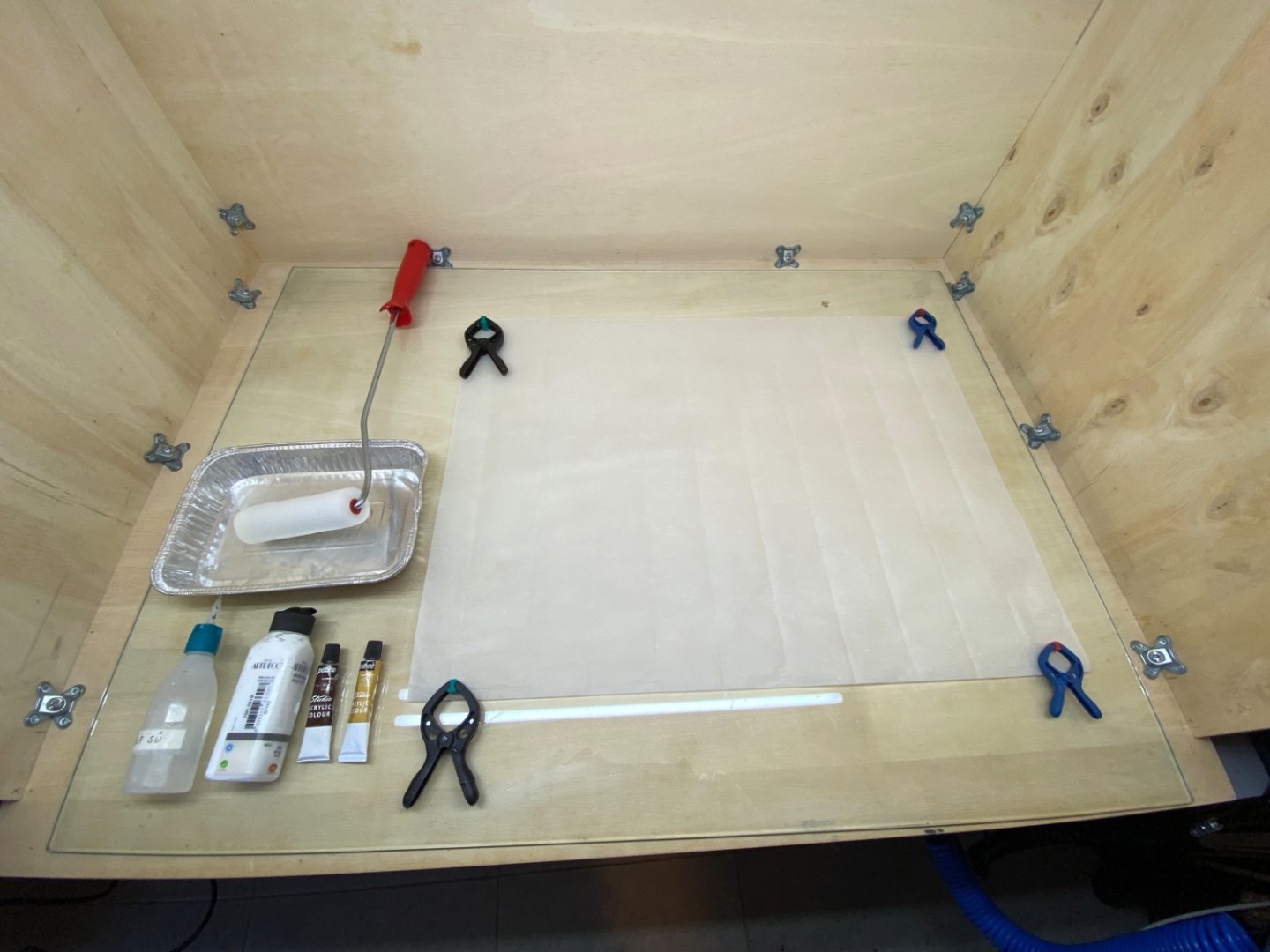
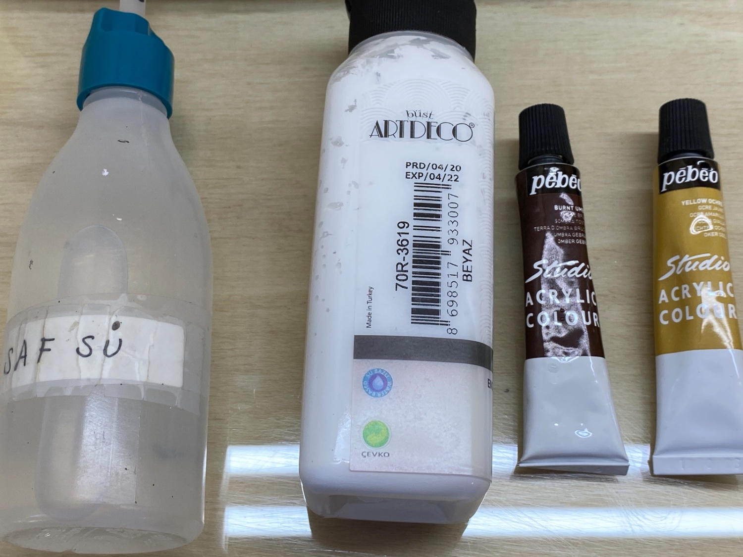
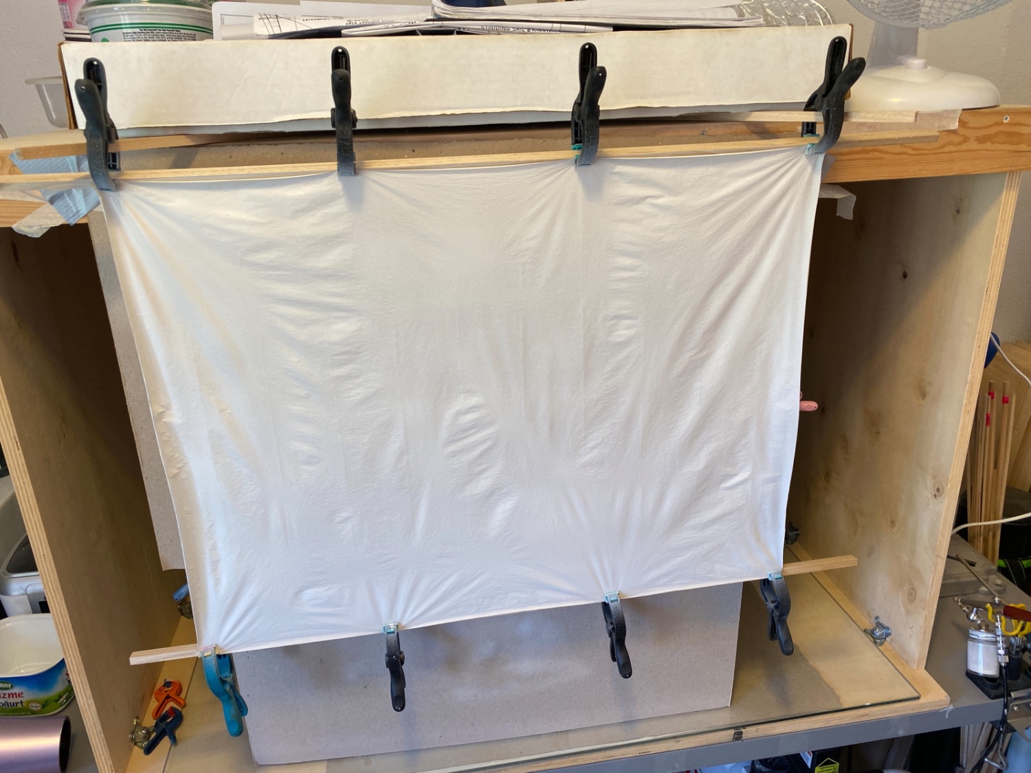
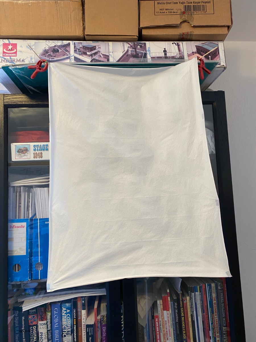
I followed Tom Lauria's method to paint the Esaki paper.
Here is the setup
Esaki paper close up photo
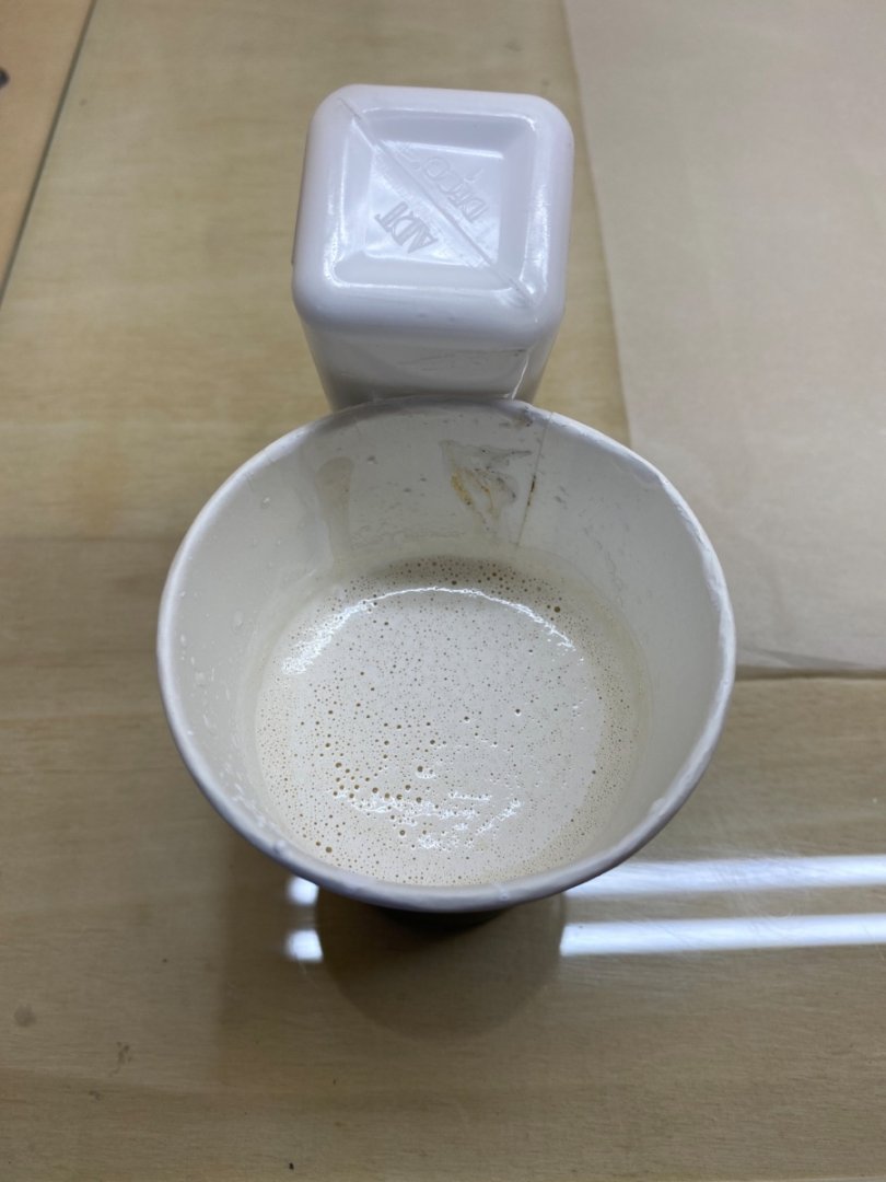
Acrylic white paint, Burnt umber or Yellow occre to color and pure water to dilute the paint.

Prepared color
Small roller and diluted paint in aluminium container.
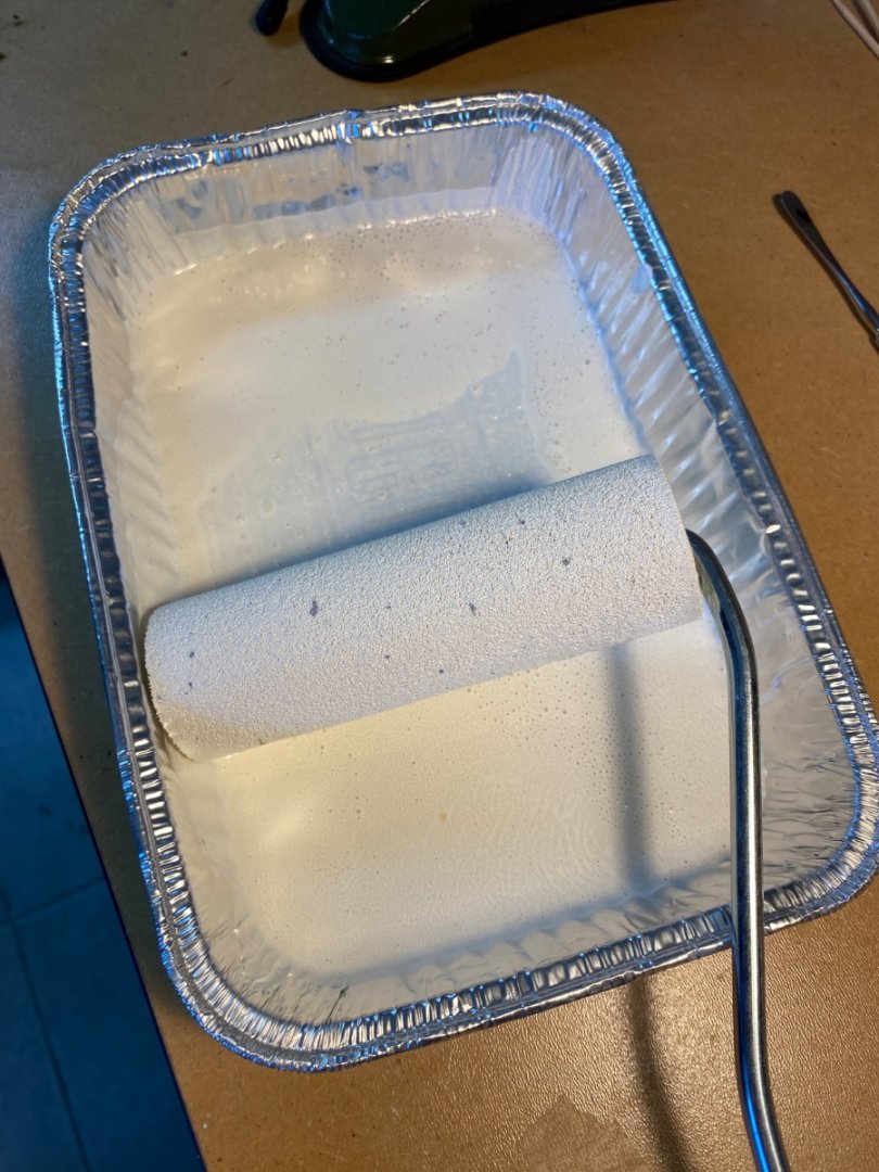
It was my mistake to dilute the paint. Tom Lauria used the paint directly from the tube without any dilution. So my first sheet of Esaki paper was ruined because excessive wetting tore it apart.
Take two attempt was done by using Paasche bottom feed single action airbrush. This time things went OK. The painted sheets were left to dry. I painted only one side of the paper. It would have been better if both sides of the paper was painted , to strengthen it.
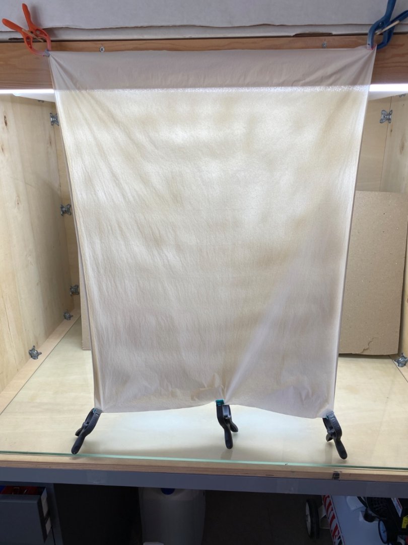
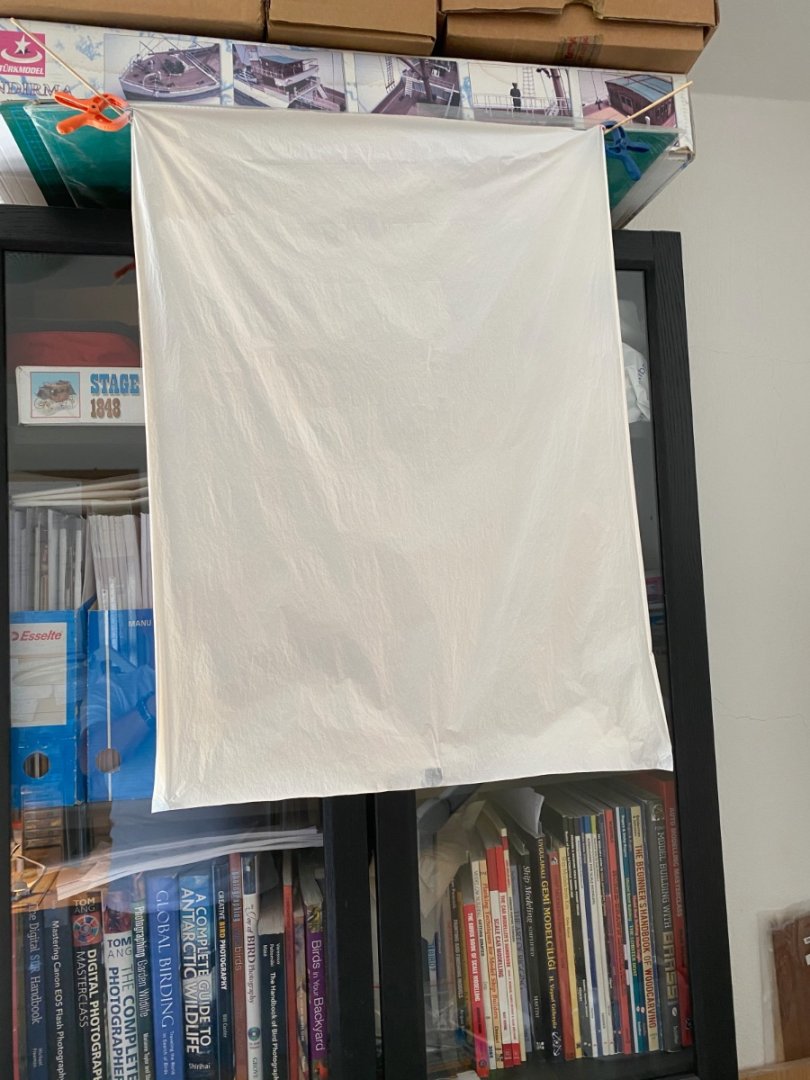
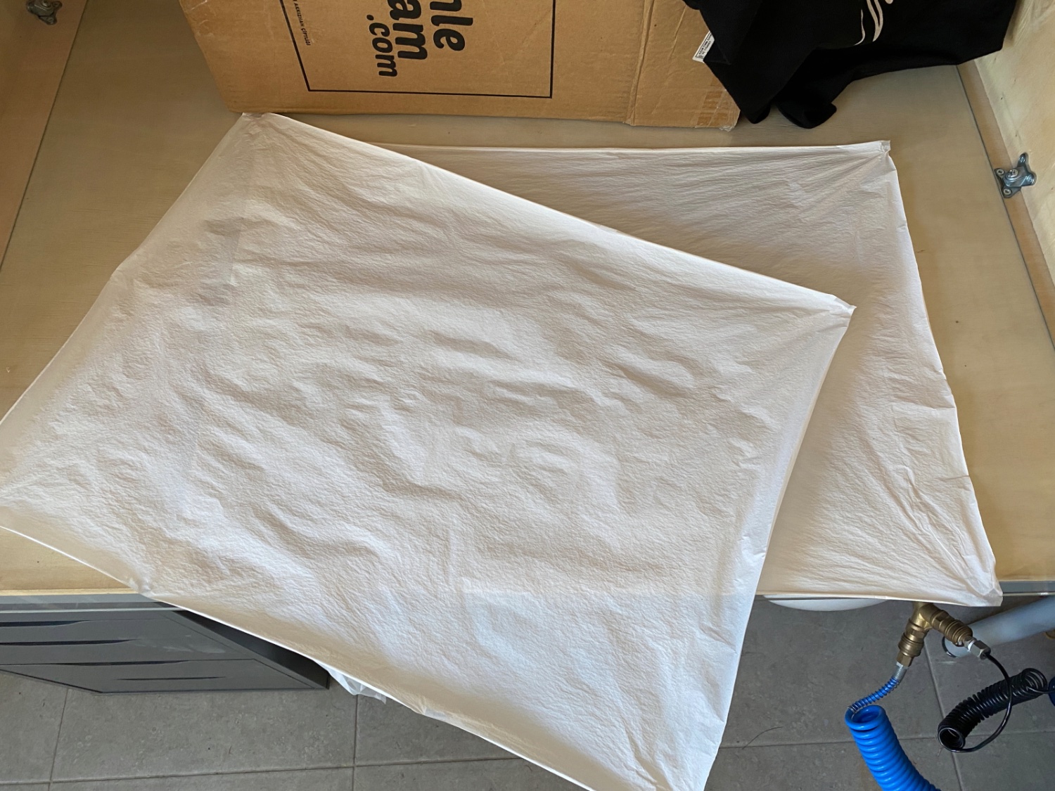
The second painted sheet


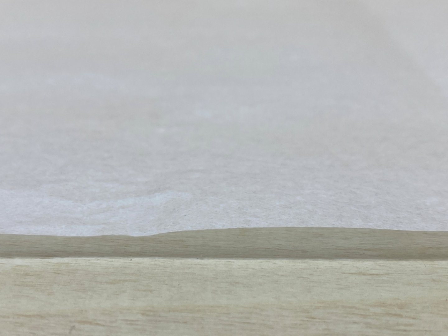
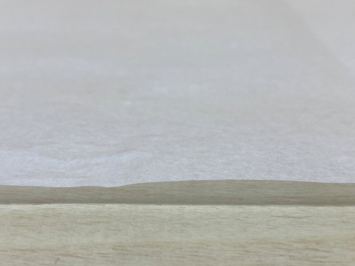
The difference between the painted and unpainted texture of the Esaki paper.
Two sheets of Esaki paper ready after painting

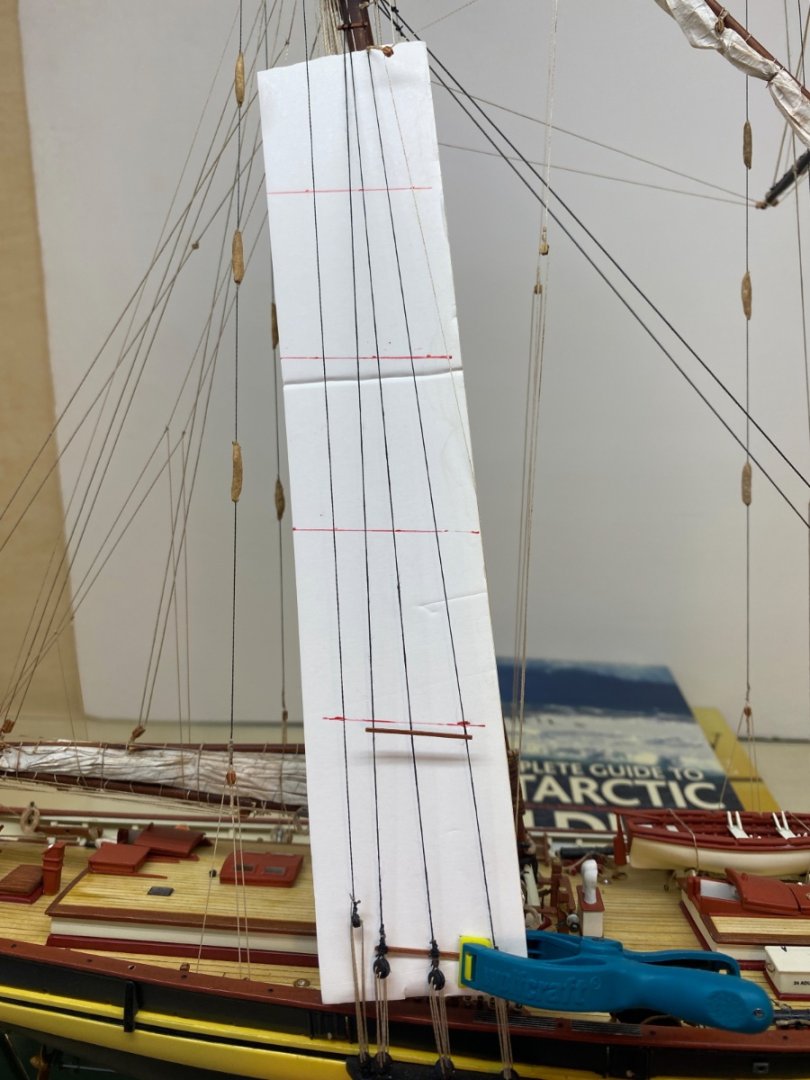
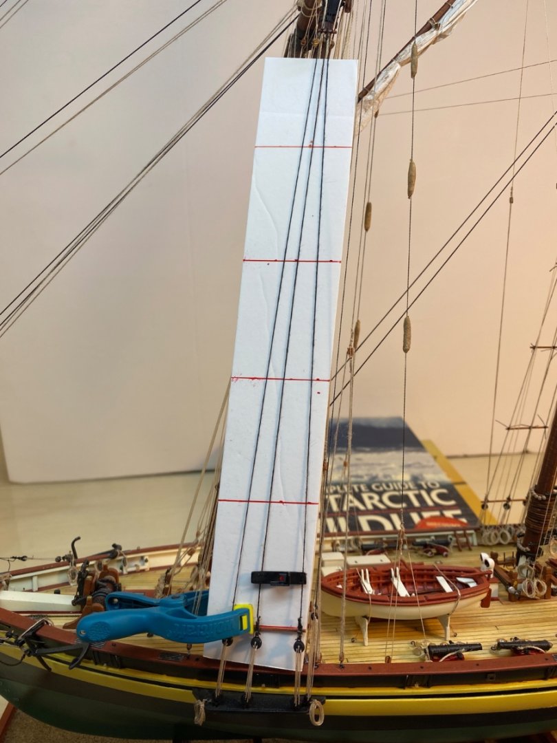
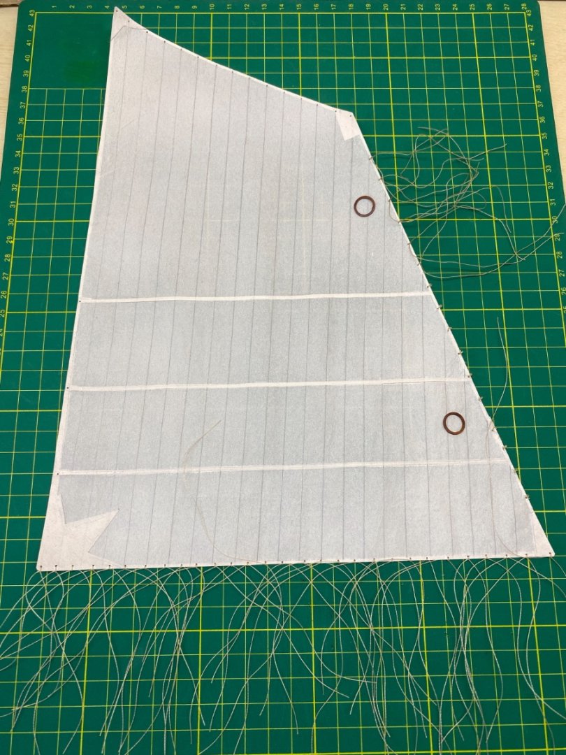
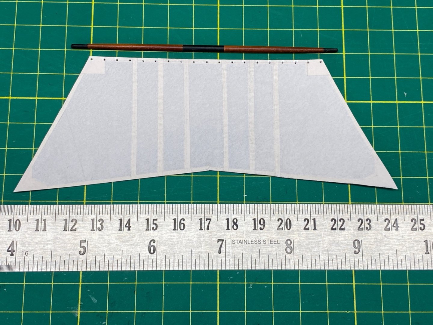
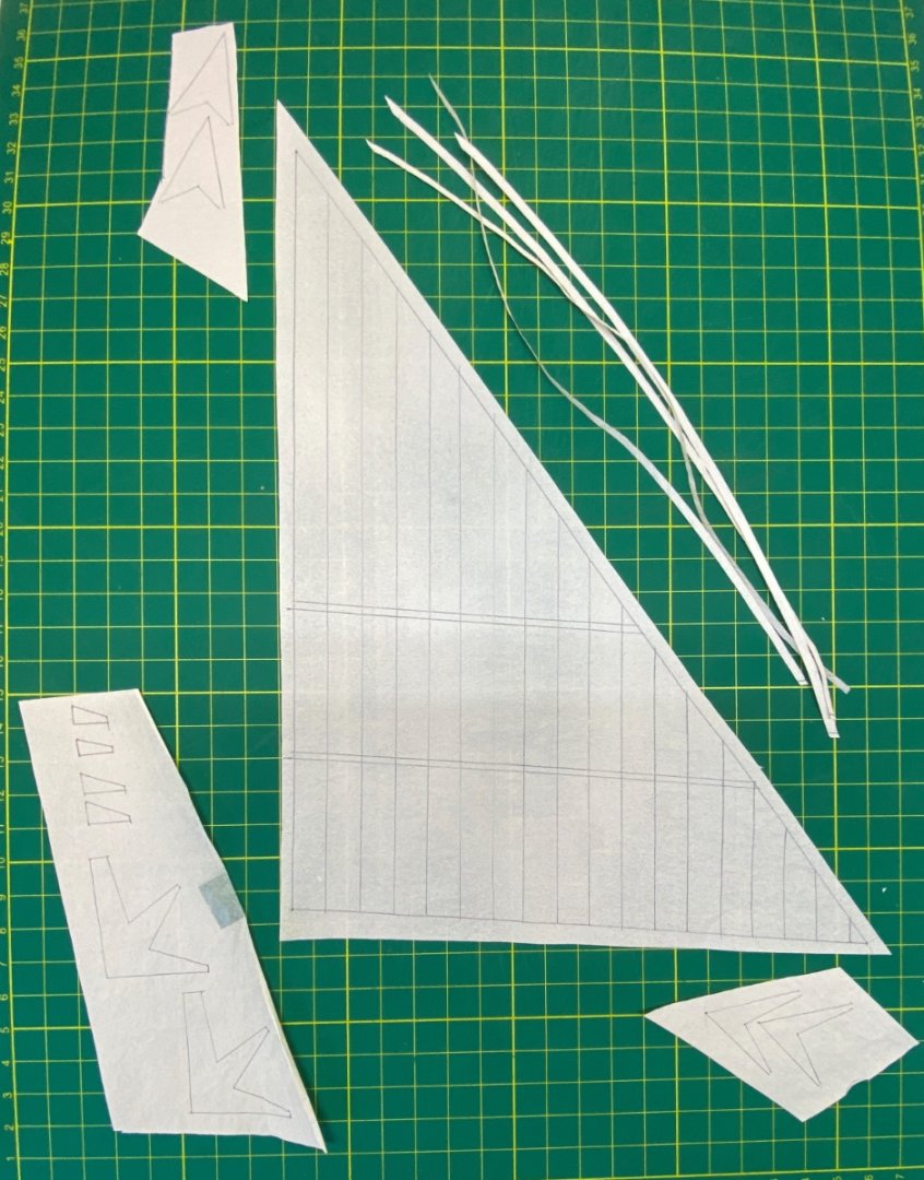
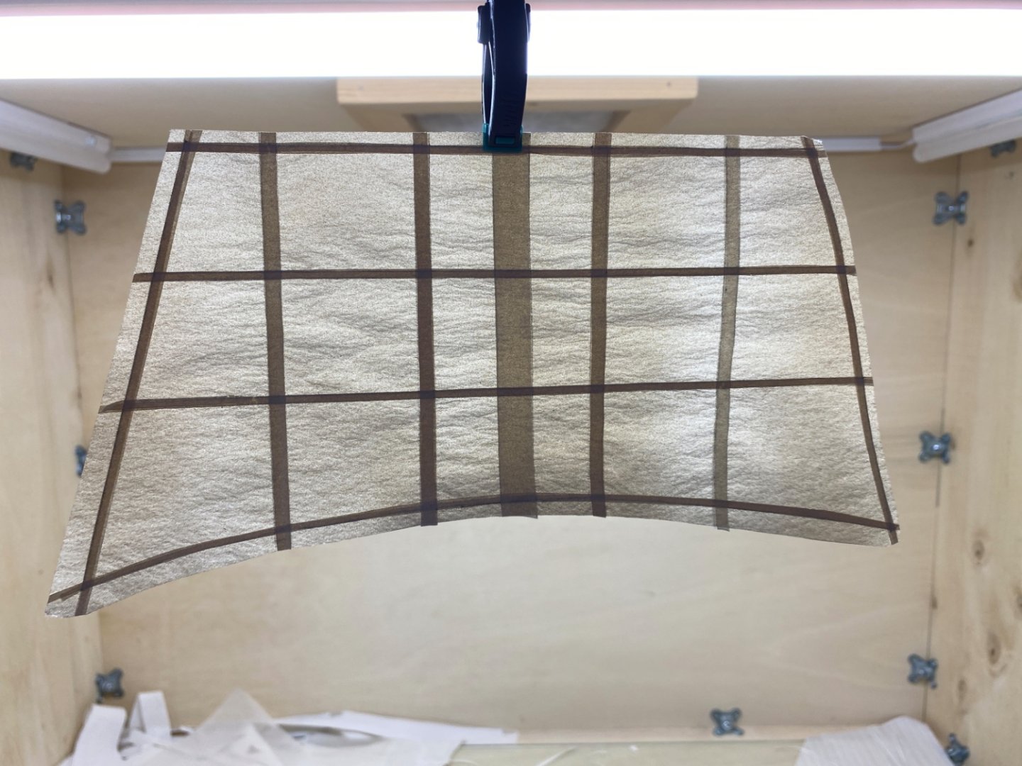
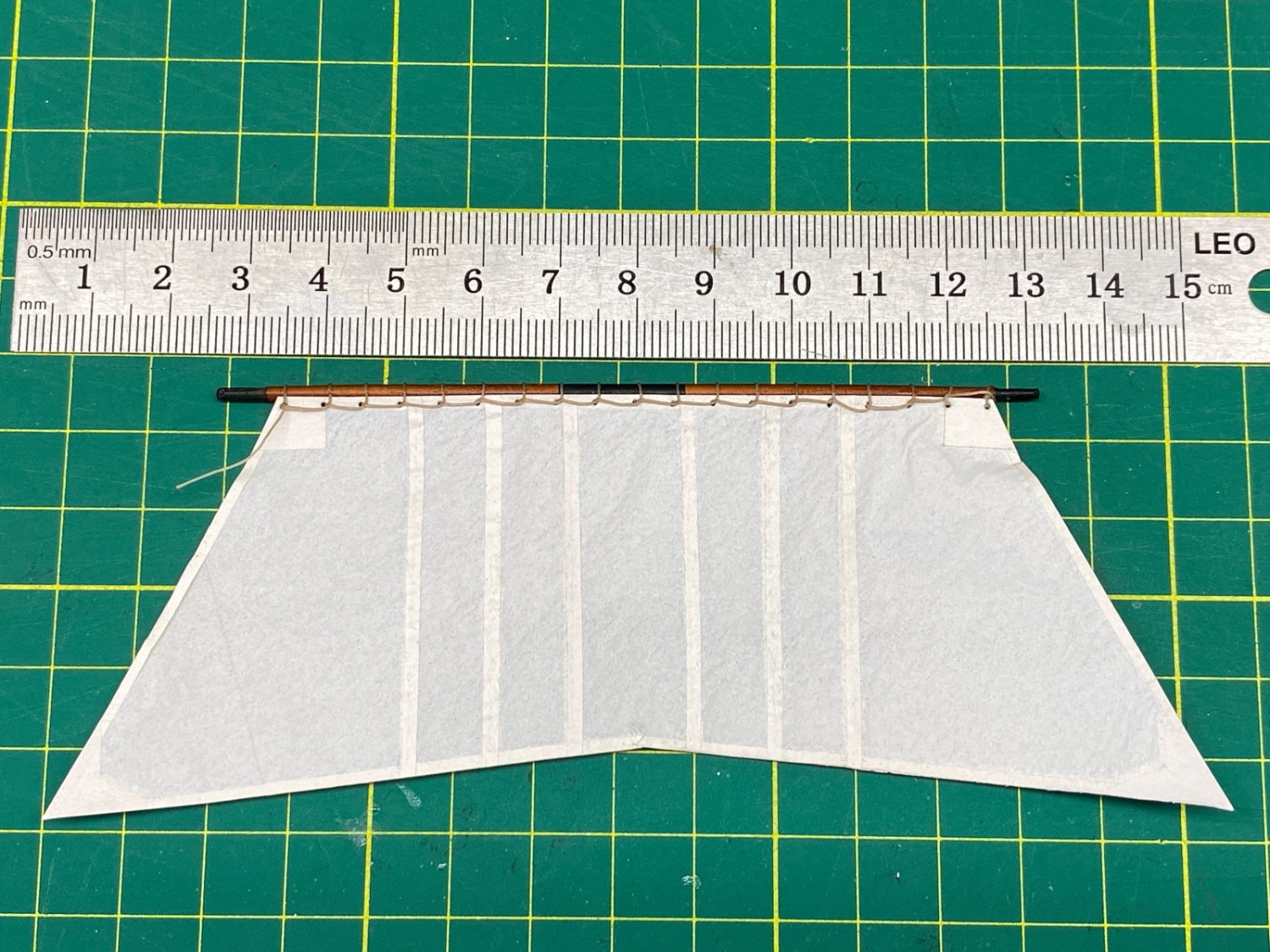
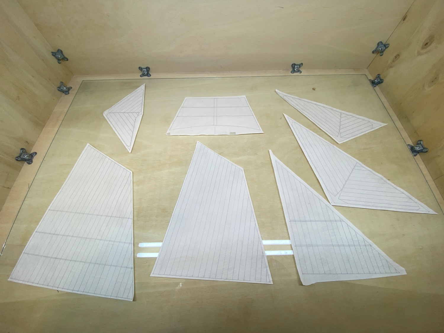
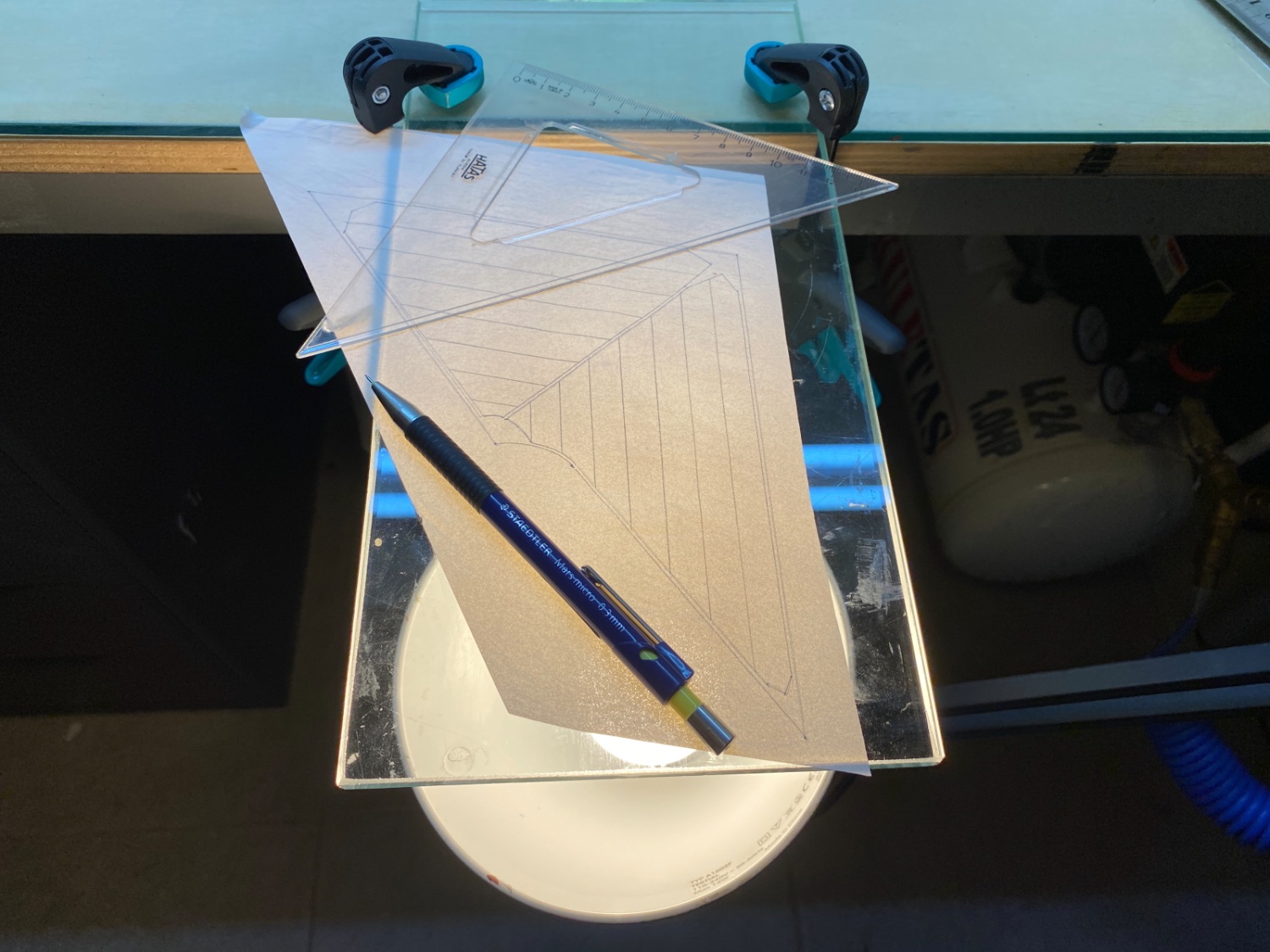
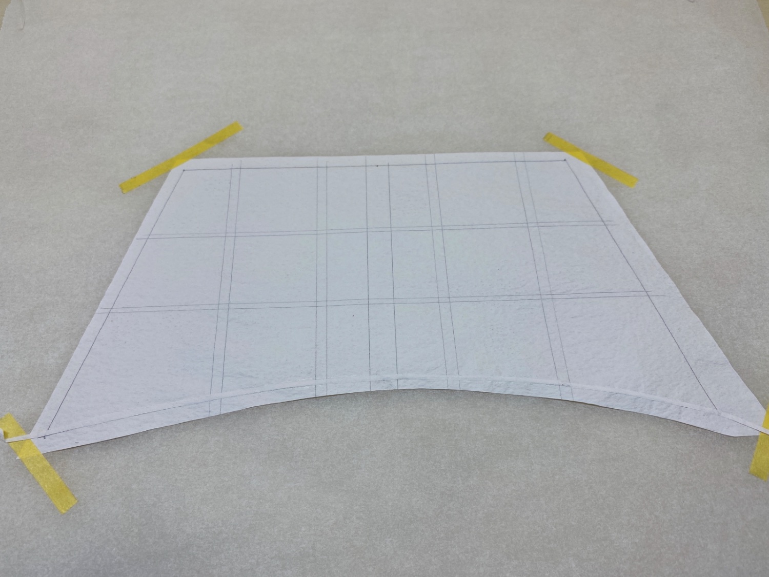
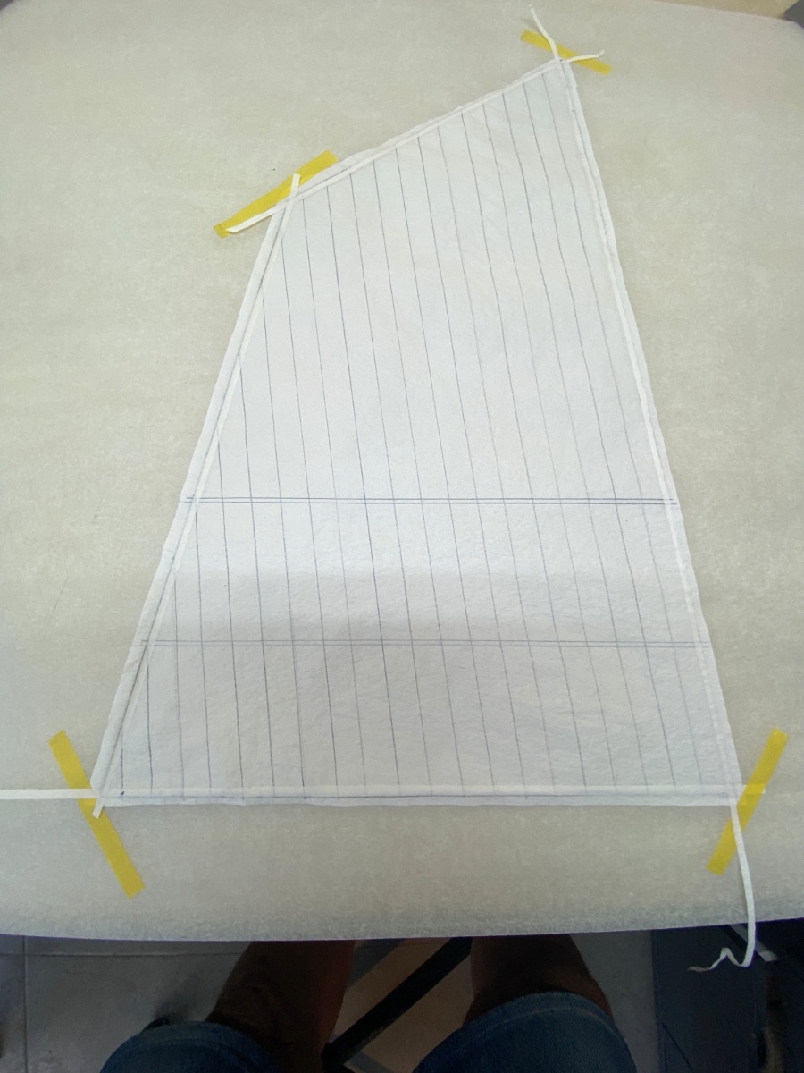
The sail patterns were transferred from the plans to the Esaki paper. Here 0.3 mm tip pen was used.
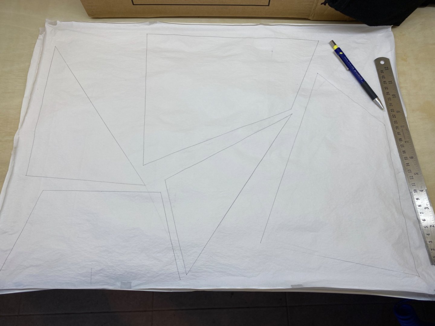
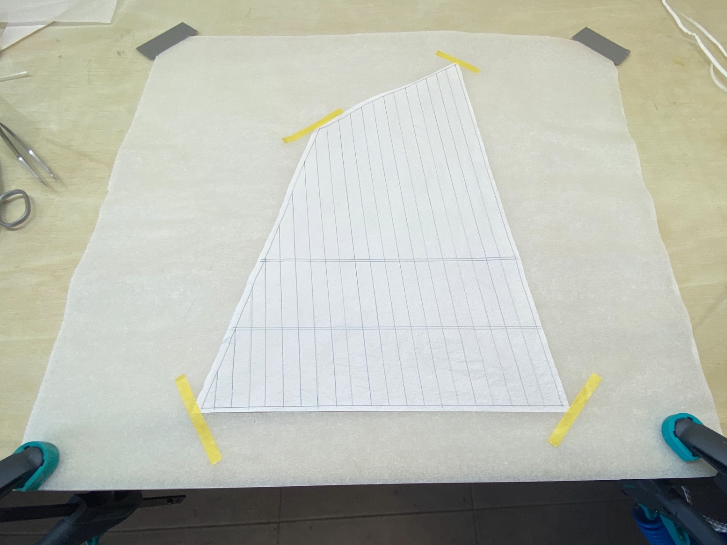
Seams, hems, reef bands and reinforcement corner patches were drawn with the 0.5 mm tip pen taking care to hold it lightly on the paper in order to maintain scale. Sails were cut one by one with a new #11 knife and using a steel ruler leaving at least 0.5 cm excess at the borders preferably on a glass surface . Reverse side lines were drawn by placing the sail on a piece of glass illuminated from below.


At this step thins strips for hem and reef bands and patterns for corner and other reinforcement patches were drawn and cut.
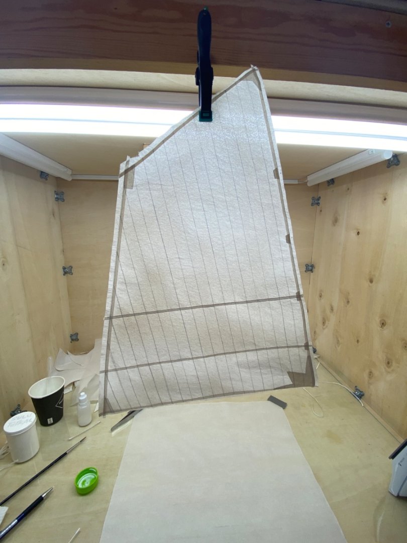
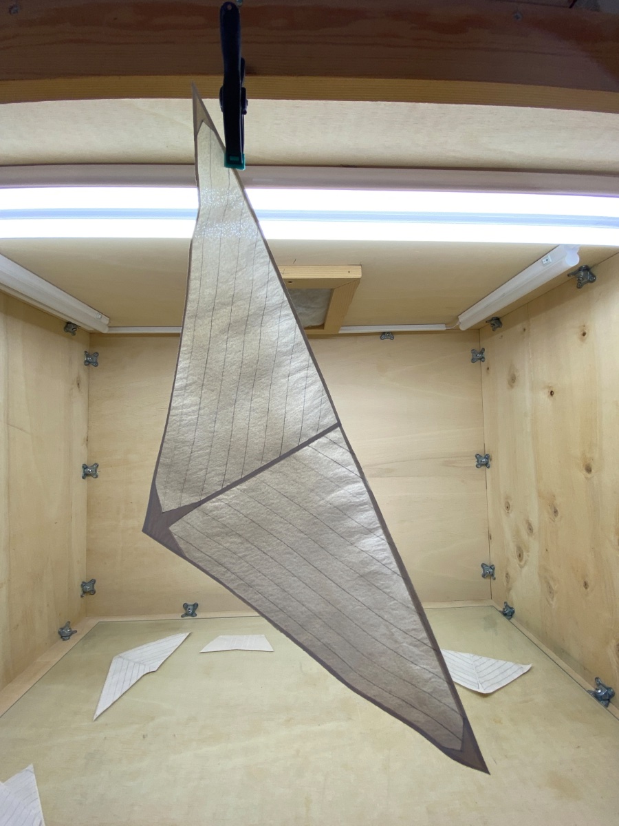
Main sail
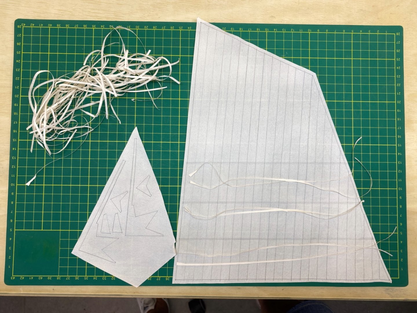
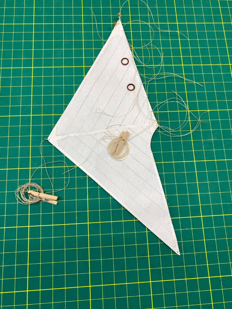
Forestay Sail
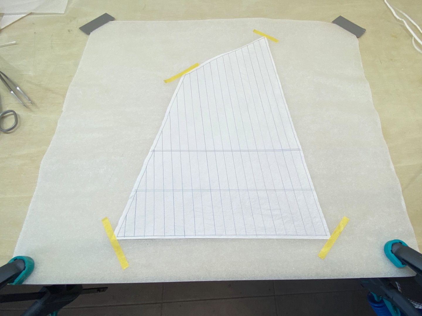
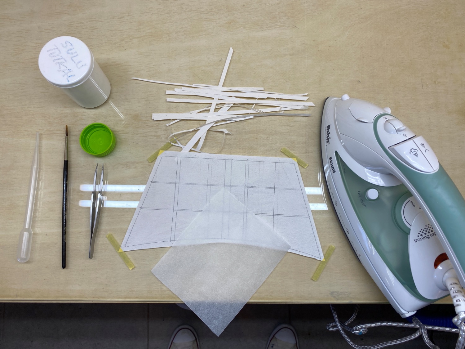
All the strips and patterns were glued to both sides of the sail making those areas 3 layered and strong. White glue diluted with water was applied by a brush and heat dried by using an iron. Here waxed oven paper must be used both under and over the sail when ironing. As you see in the setup photo of this step I did not use waxed oven paper under the sail and after ironing the sail was glued to the glass and ruined.

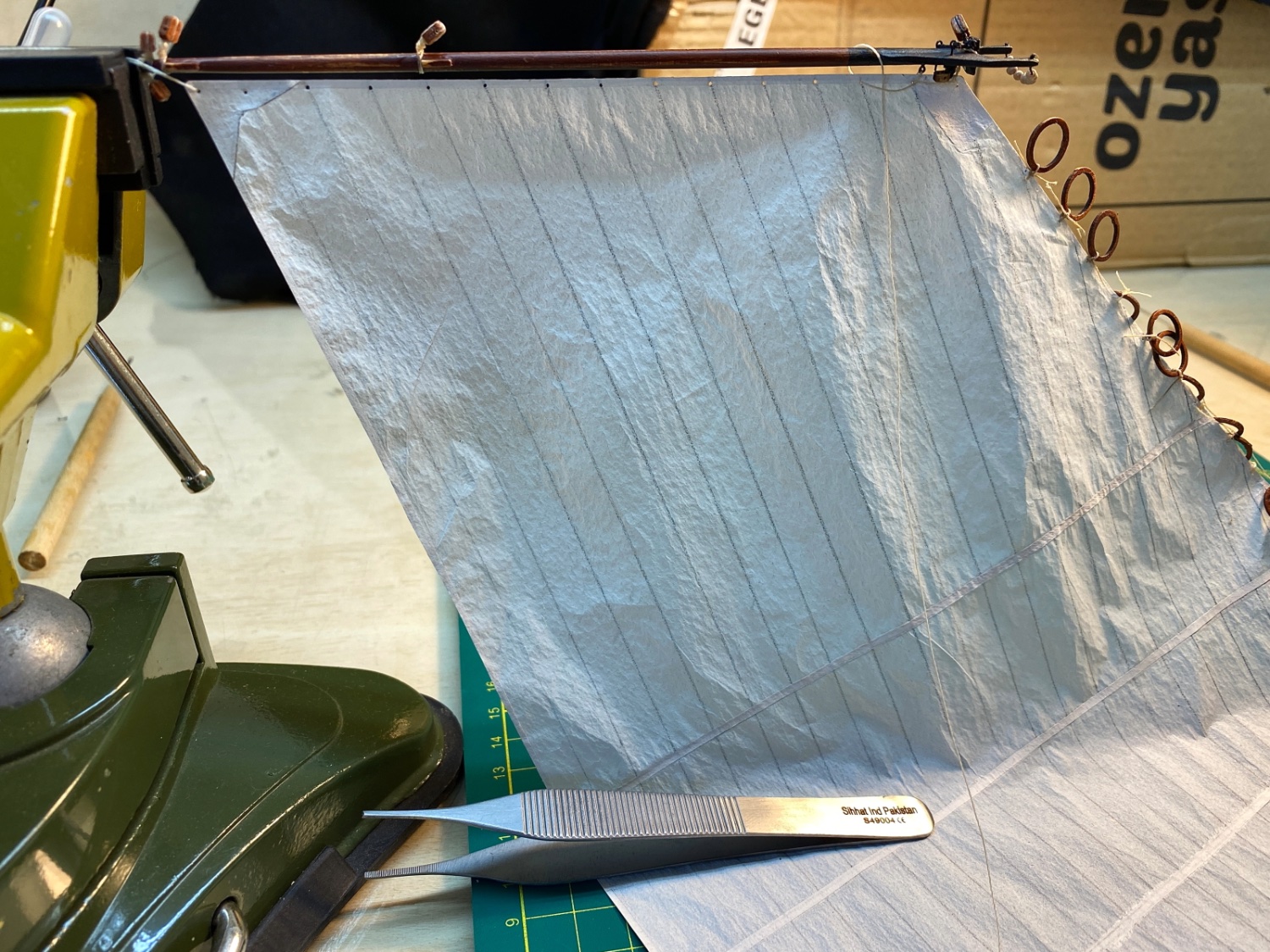
Here you see the fore topsail with waxed oven paper under it.

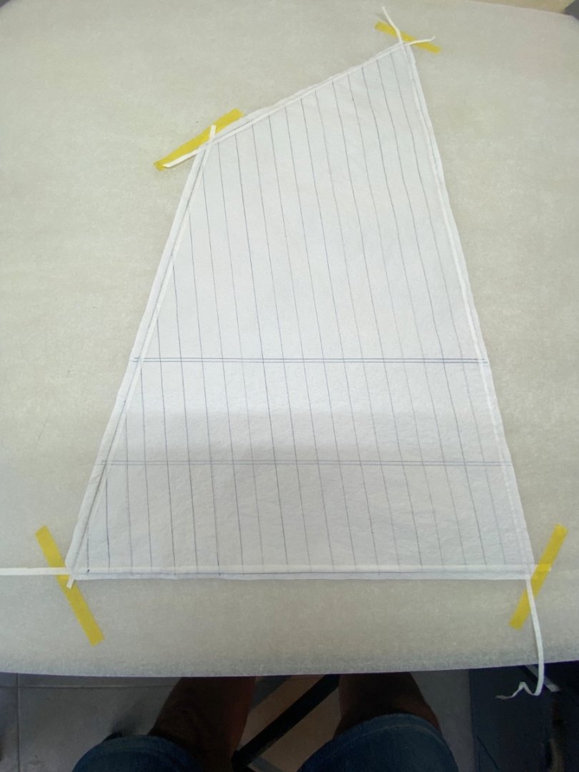
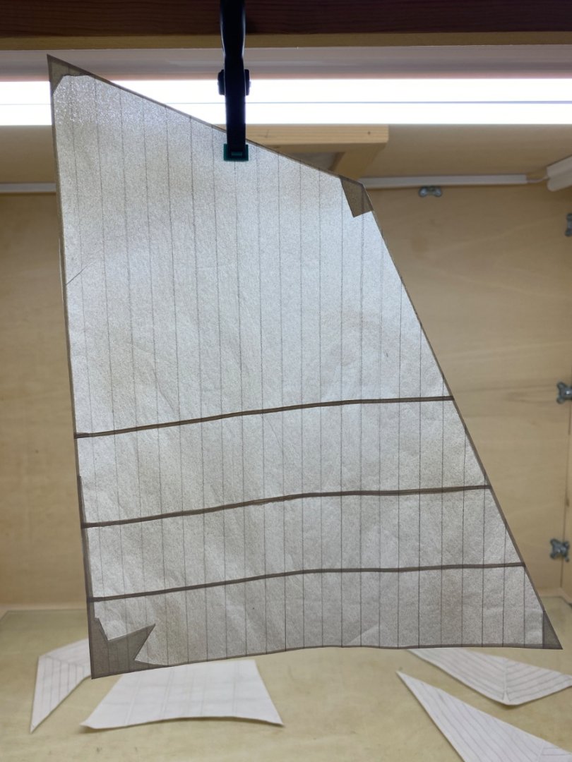
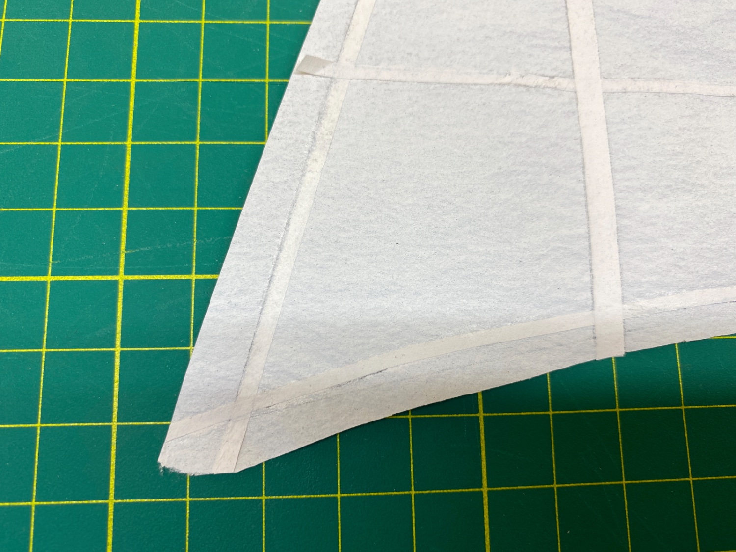
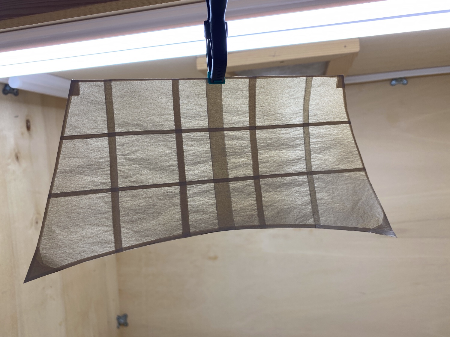
After the hem strips, reef bands and reinforcement patches were glued.

Fore sail
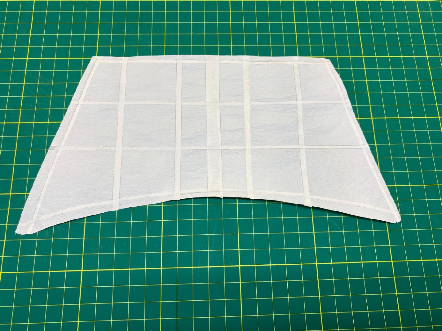
Fore Topsail and Fire sail after the gluing step. Here you can see the translucent characteristic of the paper. Imagine a full raised sail in a model and seeing through it !
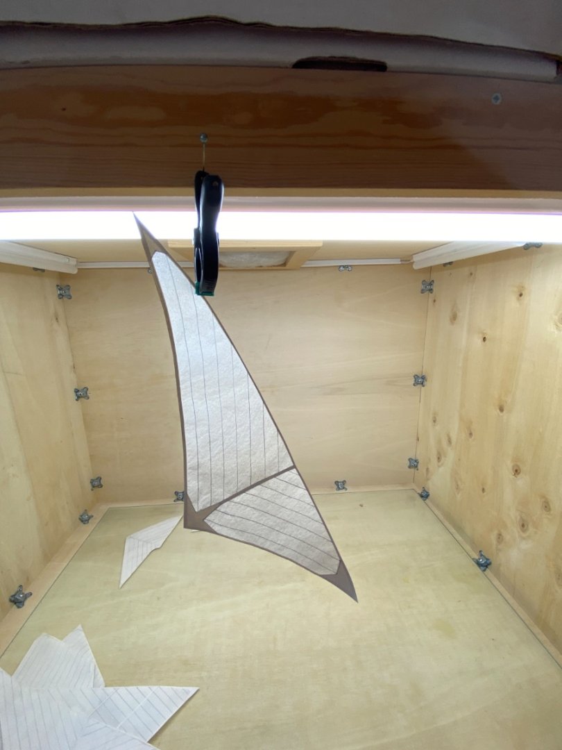
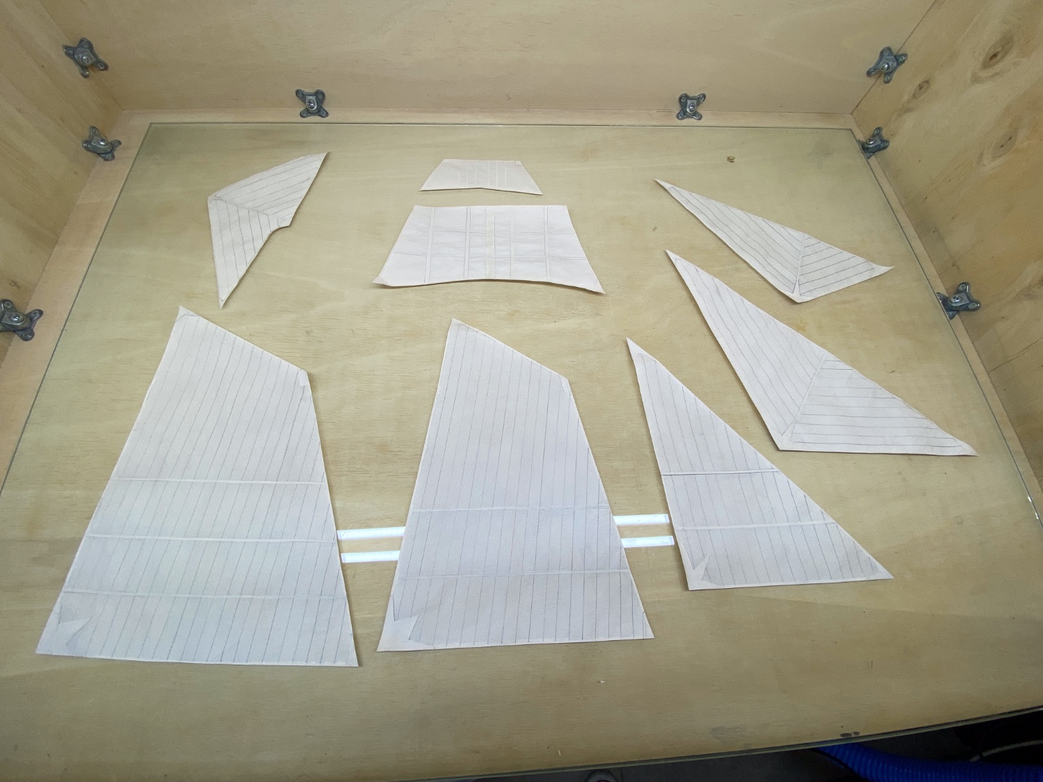
After all the sails were finished their sides are trimmed also by using #11 knife and steel ruler.

Main sail
Fore Sail
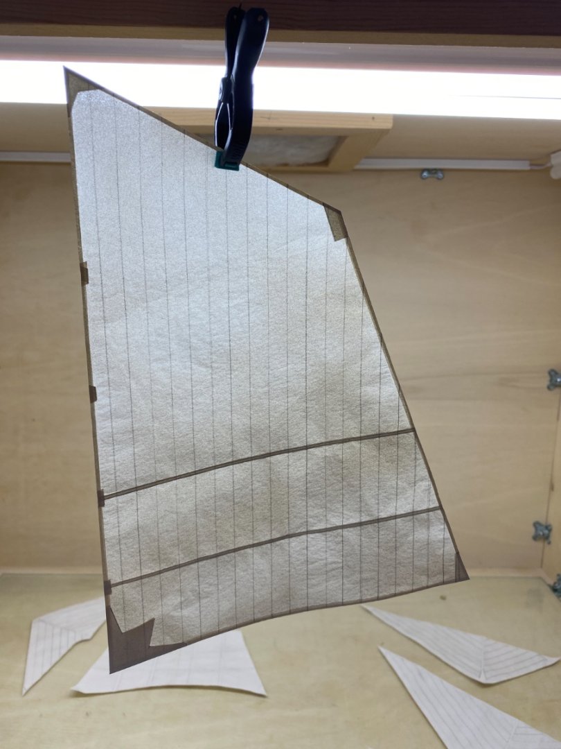 Fore topsail

Main Gaff Topsail
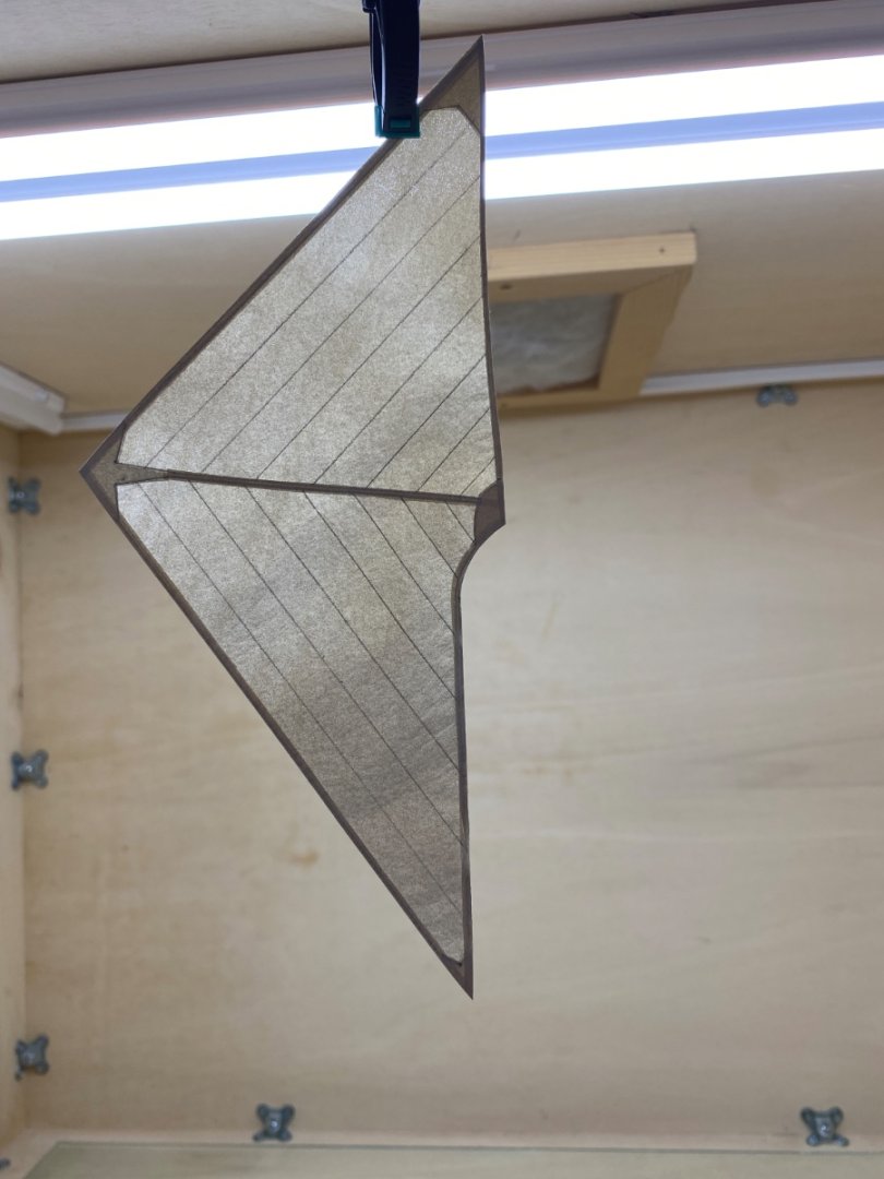
Fore Topgallant Sail
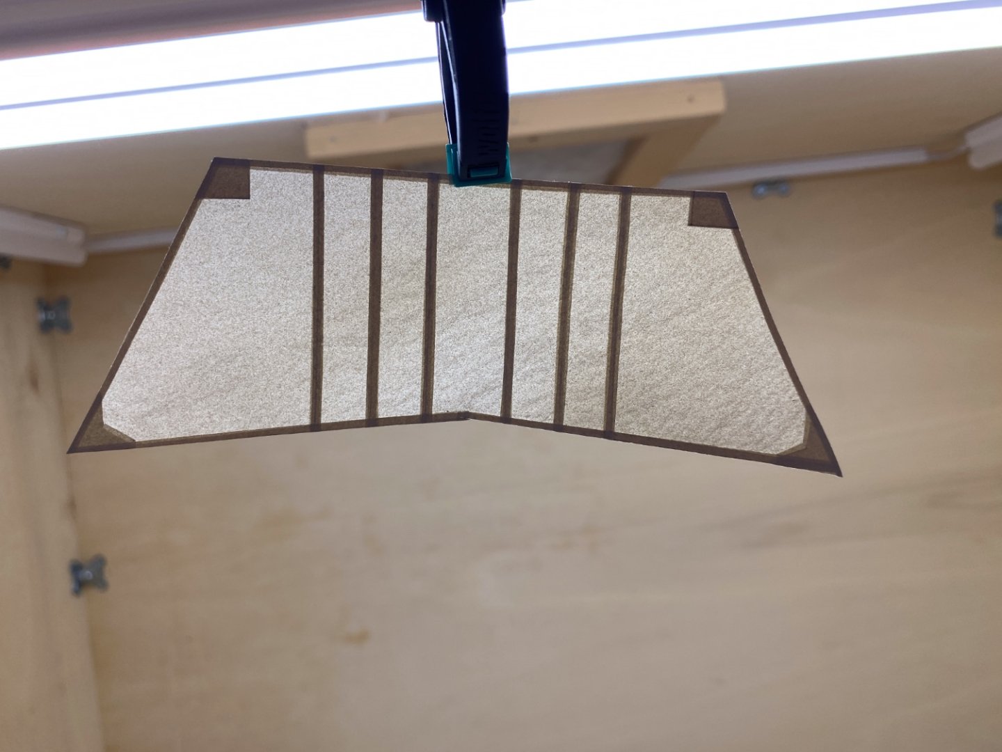
Forestay Sail
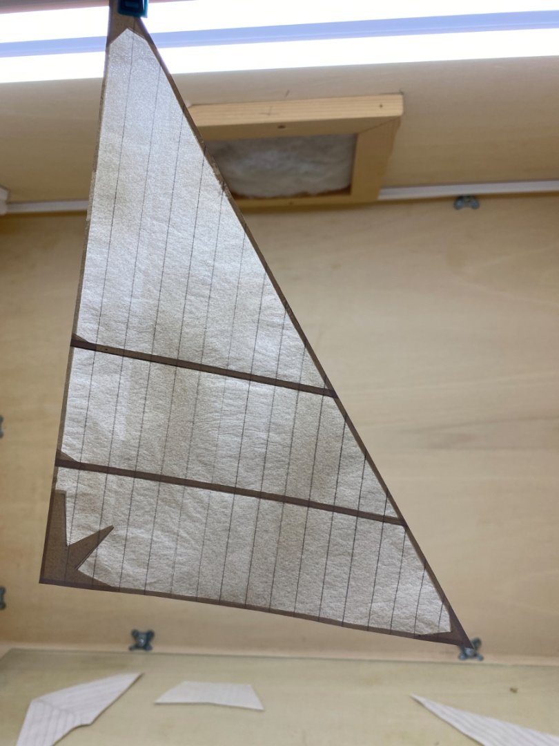
Jib

Jib Topsail
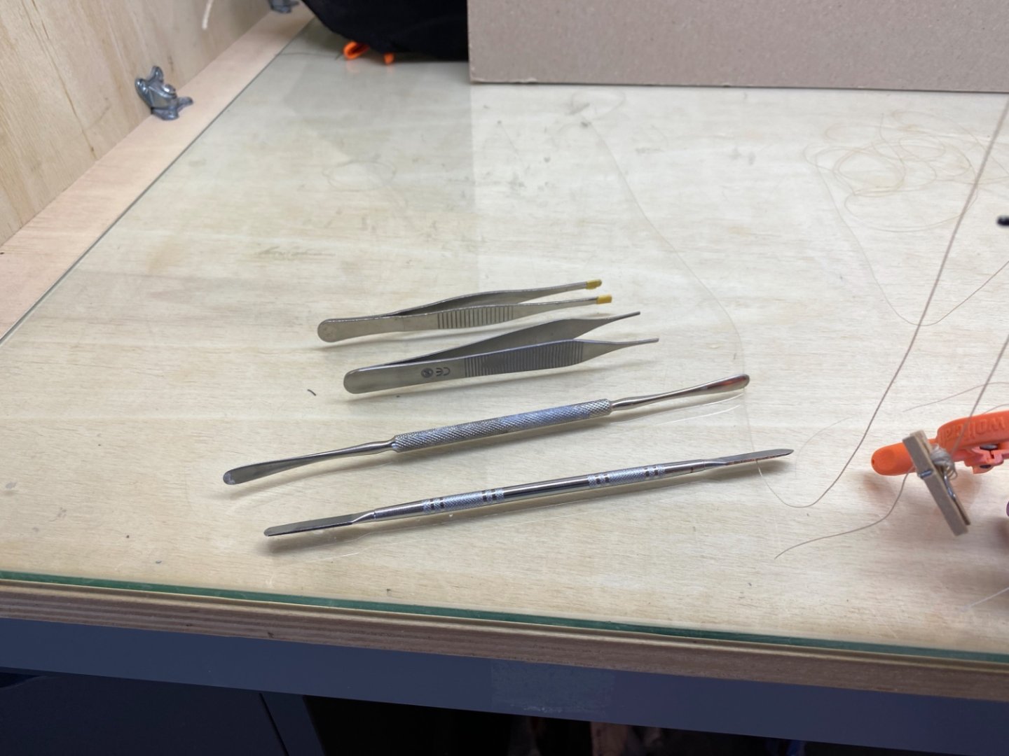
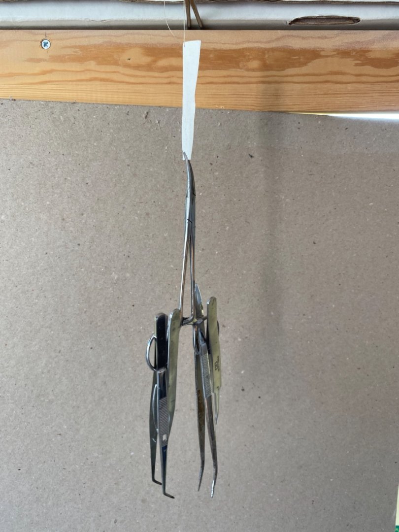
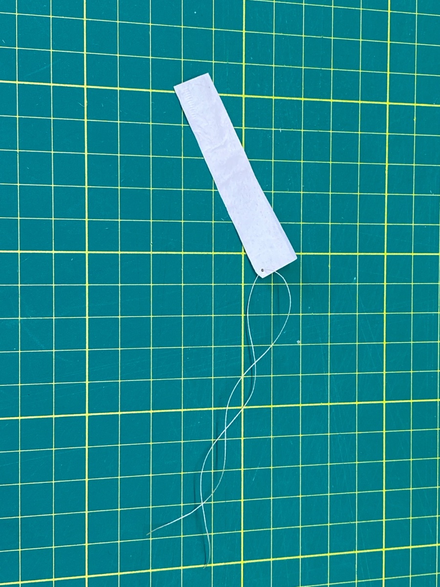
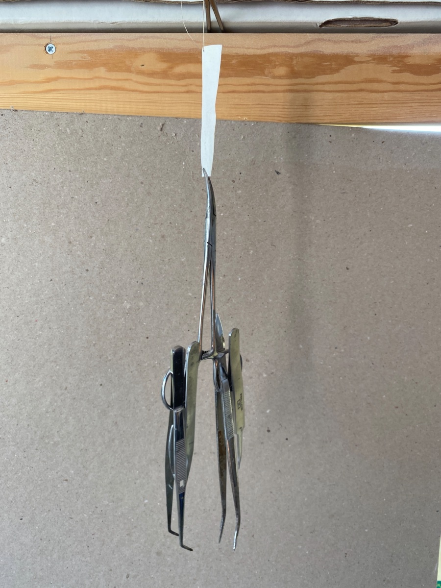
 Here is an experiment showing the strength of the three layered Esaki paper. Holding a hemostatic clamp and 4 tweezers.

- Prowler901, navid, Knocklouder and 3 others
-
4
-
2


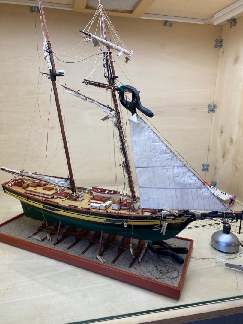
Pride of Baltimore II by halituzun - FINISHED - Model Shipways - 1:64
in - Kit build logs for subjects built from 1901 - Present Day
Posted
Thanks a lot Don..