Dave3092
-
Posts
39 -
Joined
-
Last visited
Content Type
Profiles
Forums
Gallery
Events
Everything posted by Dave3092
-
 Thanks for your comments. If you are doing this model, one thing I would particularly tell you to watch out for is preparing the deck fixtures and mast tops for rigging ahead of time. Both belay pin racks for the masts required holes to be drilled in a couple of the vertical posts, which would have been easy before I installed them but very difficult afterwards. The same was true with the mast tops. Overall, check the rigging diagrams before you start on the deck fixtures or masts to determine what might need to be drilled before you actually get to the rigging. Good luck! I think this is a good ship to learn modeling on.
 -
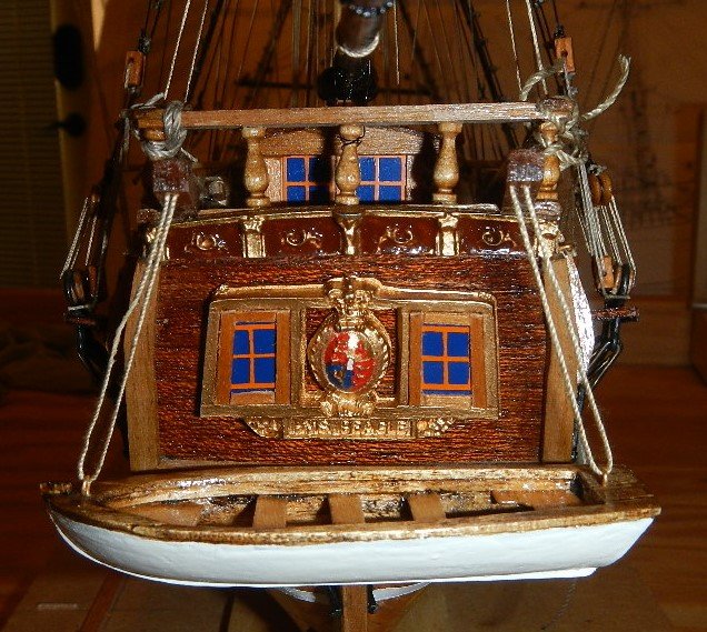
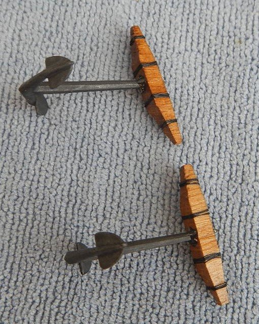
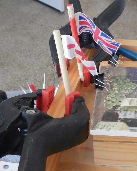
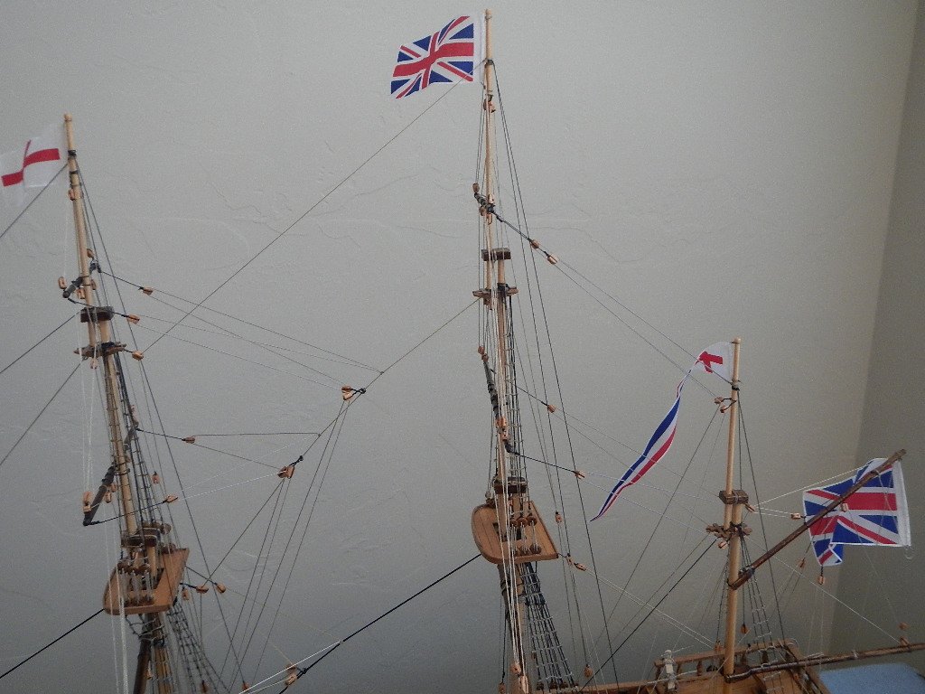
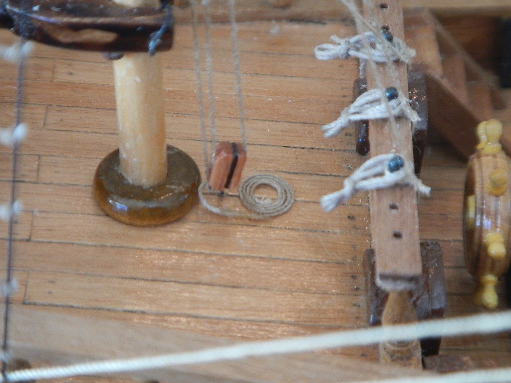
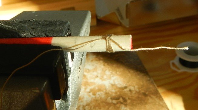
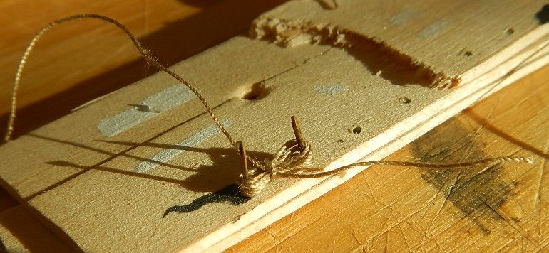
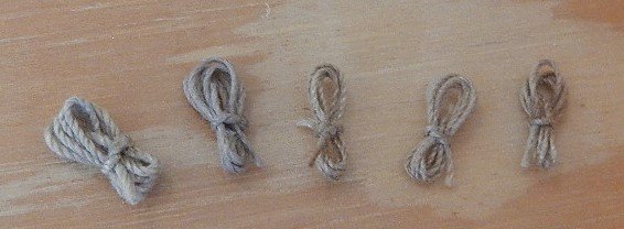
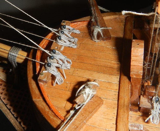
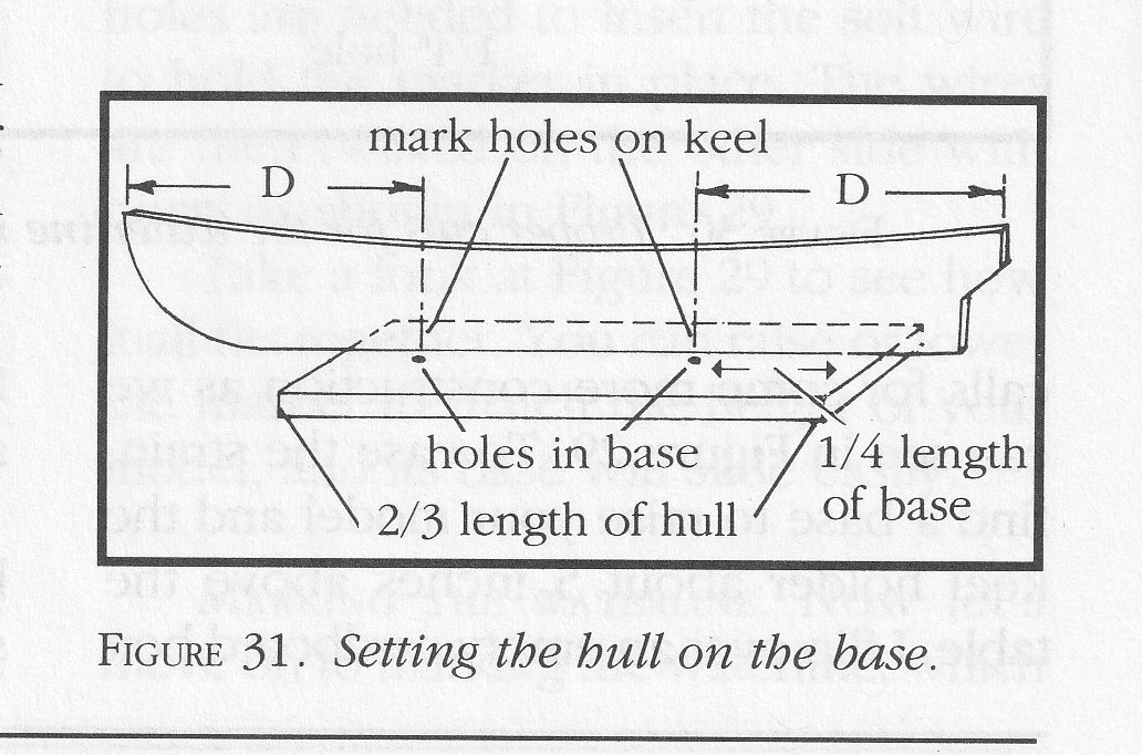
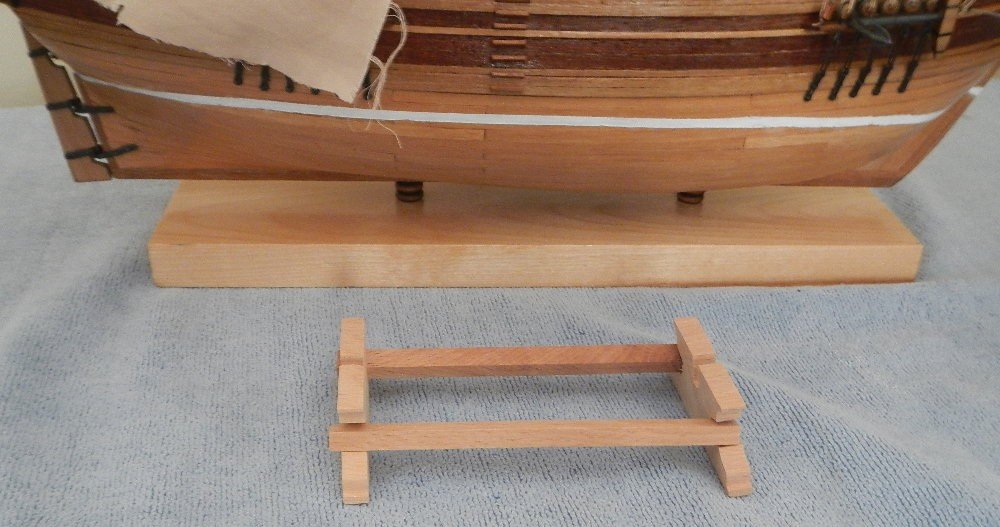
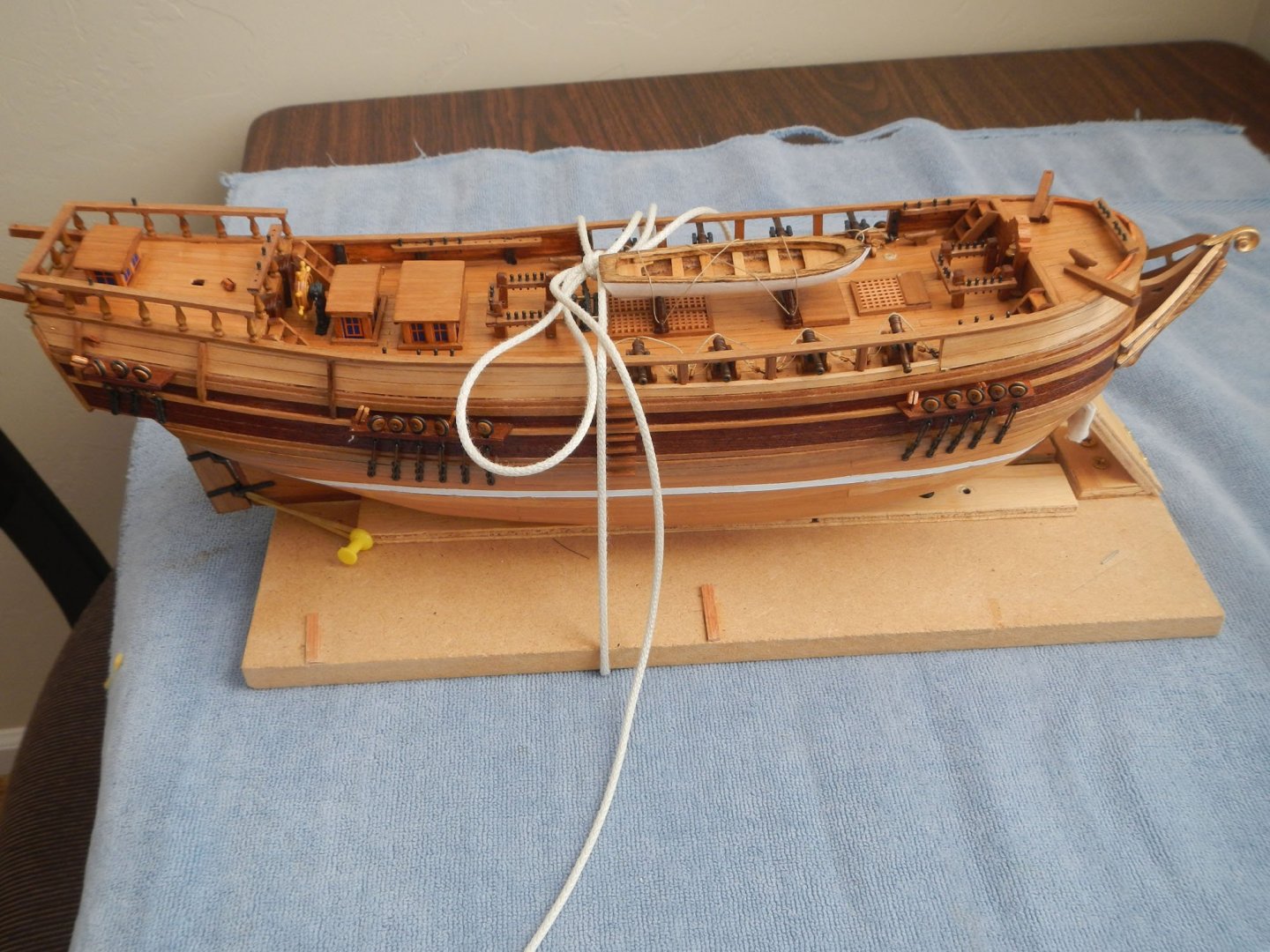
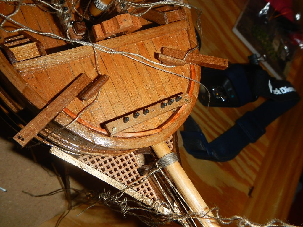
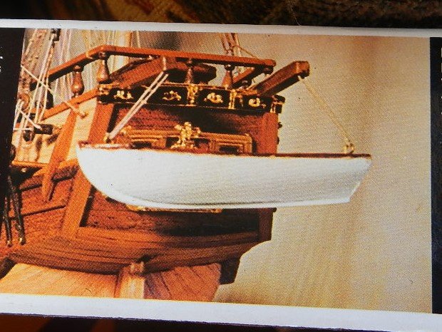
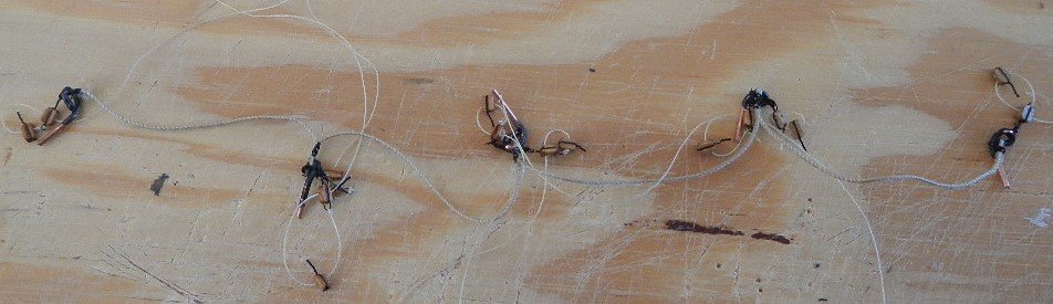
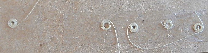
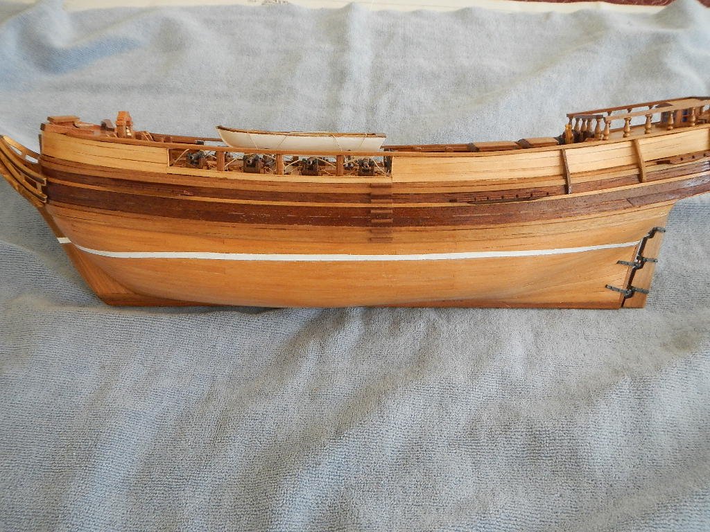
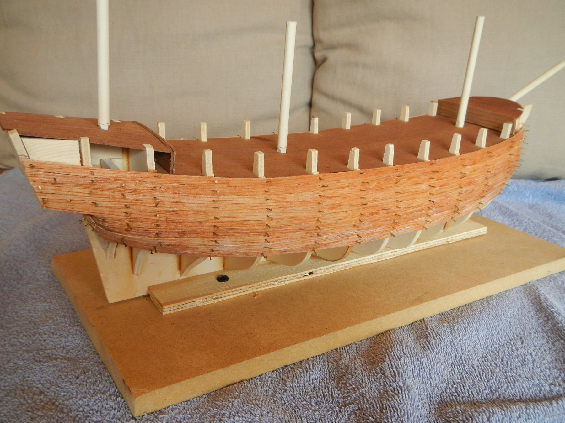
December 19,2020 Finishing Touches This build log entry covers the completing the last finishing touches on the H.M.S. Beagle. Anchors The wooden anchor cross members were, unfortunately, cut with the grain across rather than lenghtwise, so both broke when trying to fit them to the anchors. They were, however, easily glued back together. The anchors needed to be filed down (and the holes in the cross members enlarged) to get the pieces to fit. I added metal strapping to the cross members as was indicated in the drawing, although it was not mentioned in the instructions. The anchors were then mounted on the foremast shroud supports and rigging lines run from the davit and a hole in the bow. Aft Lifeboat The aft lifeboat was hung from the davits and secured to cleats of my own construction (as I thought that the rings provided didn’t look appropriate). I set the lifeboat part way down so that it would not hide the stern transom moulding, as I really liked the way it had turned out and wanted it visible. There is even a workmanlike rendition of the British Coat of Arms (at least for that scale). Model Base I thought that the model base was pretty inadequate for the ship. SMS recommends a longer base. Using the recommendations of SMS, I obtained a piece of birth 1x4 plank, then drilled holes in the hull at the intersections of the keel and frames at the appropriate distance. I added two wooden beads to raise the ship slightly off the plank. The end result was a clean and very sturdy base for the ship (the plank weighs about as much as the ship). Flags There were four flags provided in the kit. In order for them to drape more realistically, I mounted them temporarily on wood dowels, sprayed them with starch and then weighed down the bottom corner of the flag until they dried. Here is how they look on the ship. Rope Coils Although not mentioned in the instructions, they were recommended in SMS to add detail to the model. To create the coils for the belay pins, I wrapped the rigging line around a dowel and tied it off adding some fabric glue. I then placed the tied loop on a tying jig I made with two brads in balsa wood. This held the loop in place while I tied the ends and glued. I then trimmed the excess line. In addition, I added four deck rope coils for the Topsail halyards for both masts, the mainmast jeer and the mizzenmast boom halyard. These were coiled on double-sided tape, then coated with varnish. When dried I applied them on the end of the lanyard on the deck. This coil was the very last thing added to the ship. Total Build time – 607 hrs: 23 hrs for the work in this build log entry. Fun facts: The breakdown of the build time is: Build Segment Build Time Percentage Time Preparatory work 45 7.4% Hull & Deck 215 35.4% Deck Fixtures 115 18.9% Masts & Rigging 209 34.5% Finishing 23 3.8% Total 607 100% There are 55 rope coils on belay pins, and 20 rope coils on the deck (including the 16 coils I had added for the cannon earlier). SMS – Ship Modeling Simplified by Frank Mastini
-
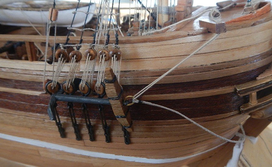
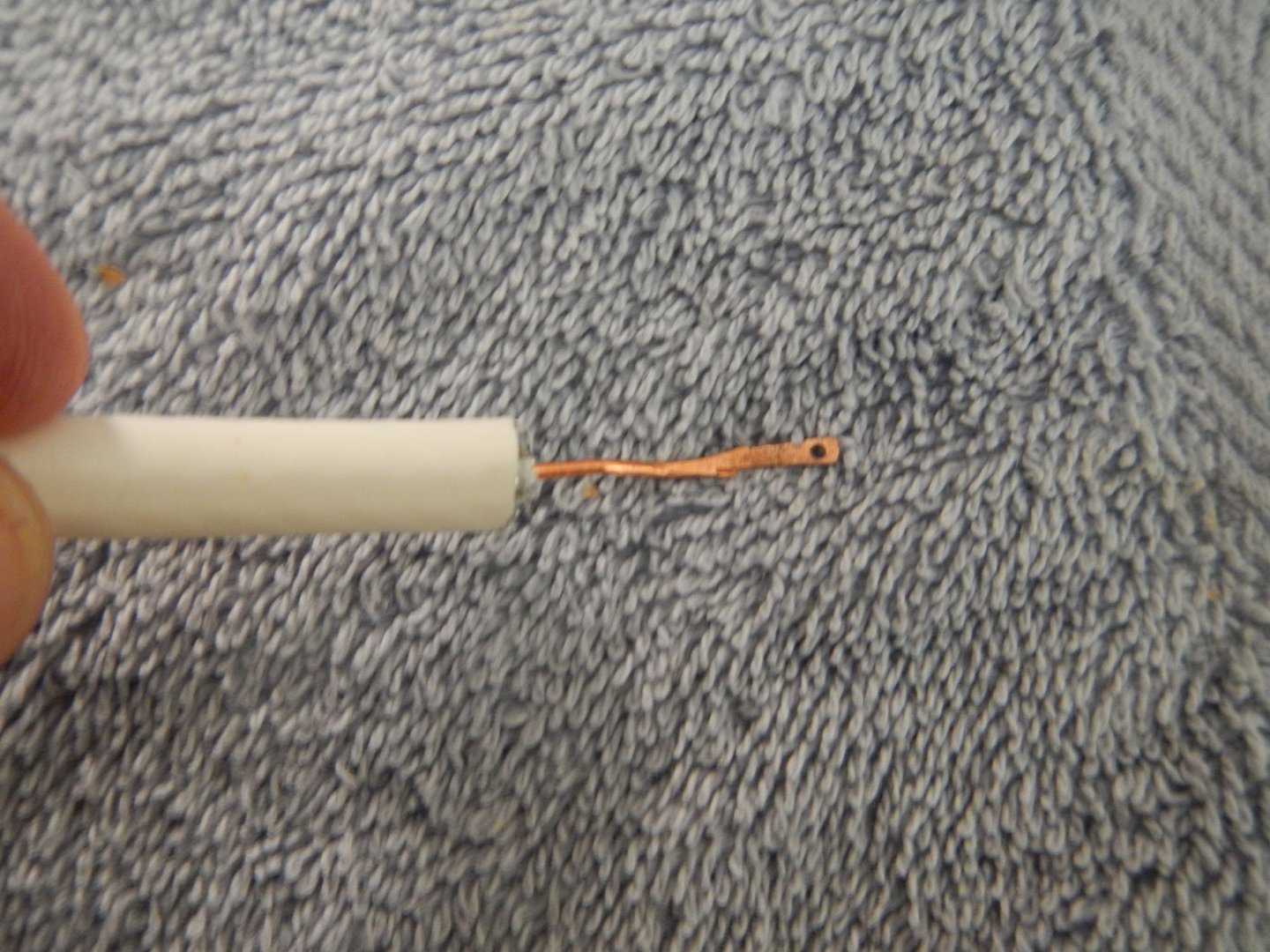
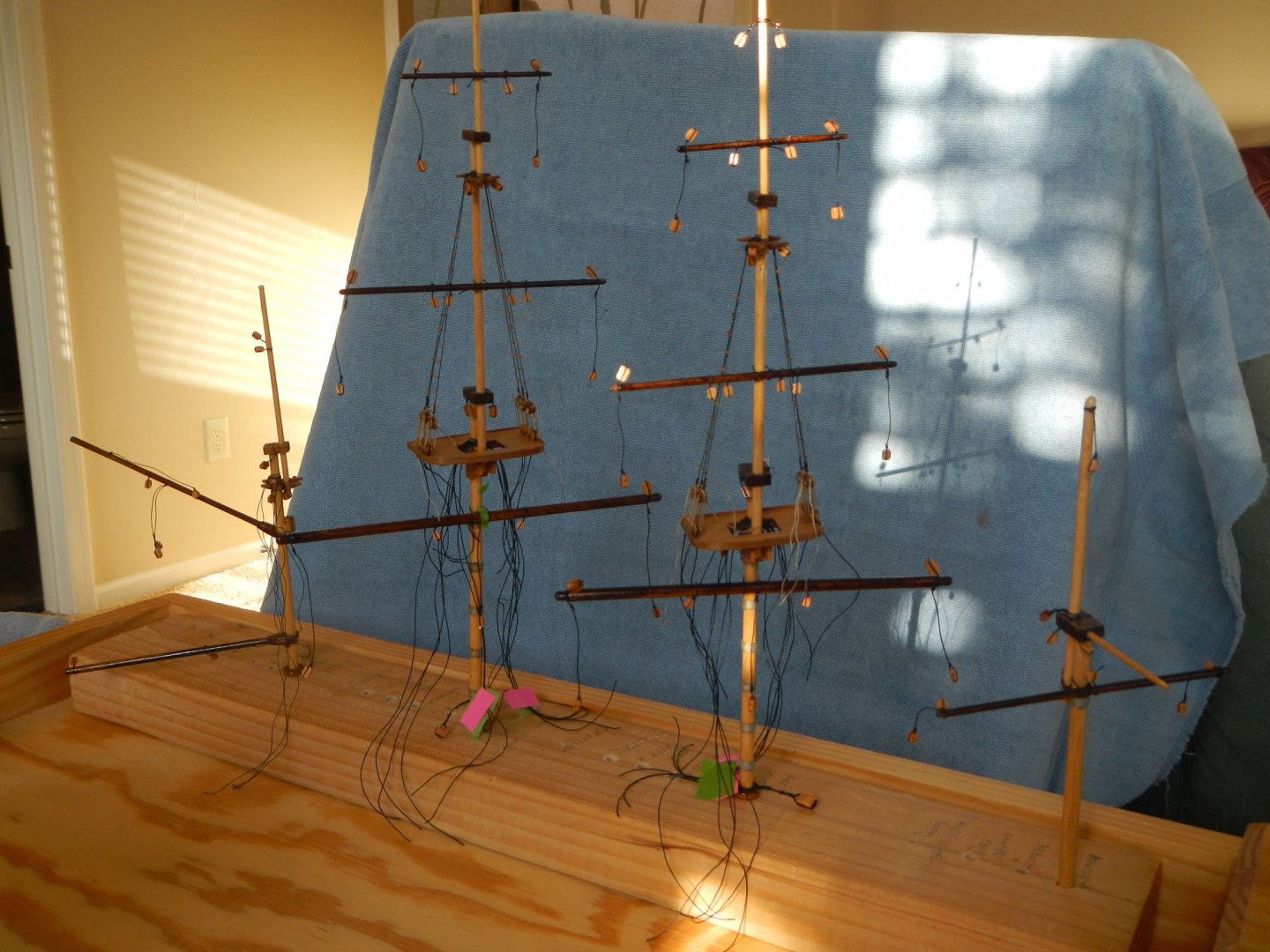
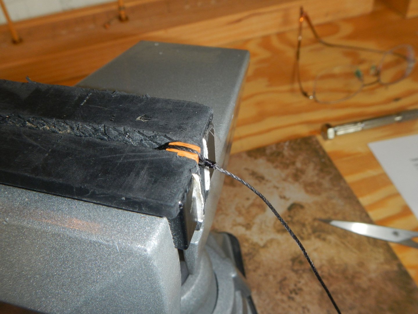
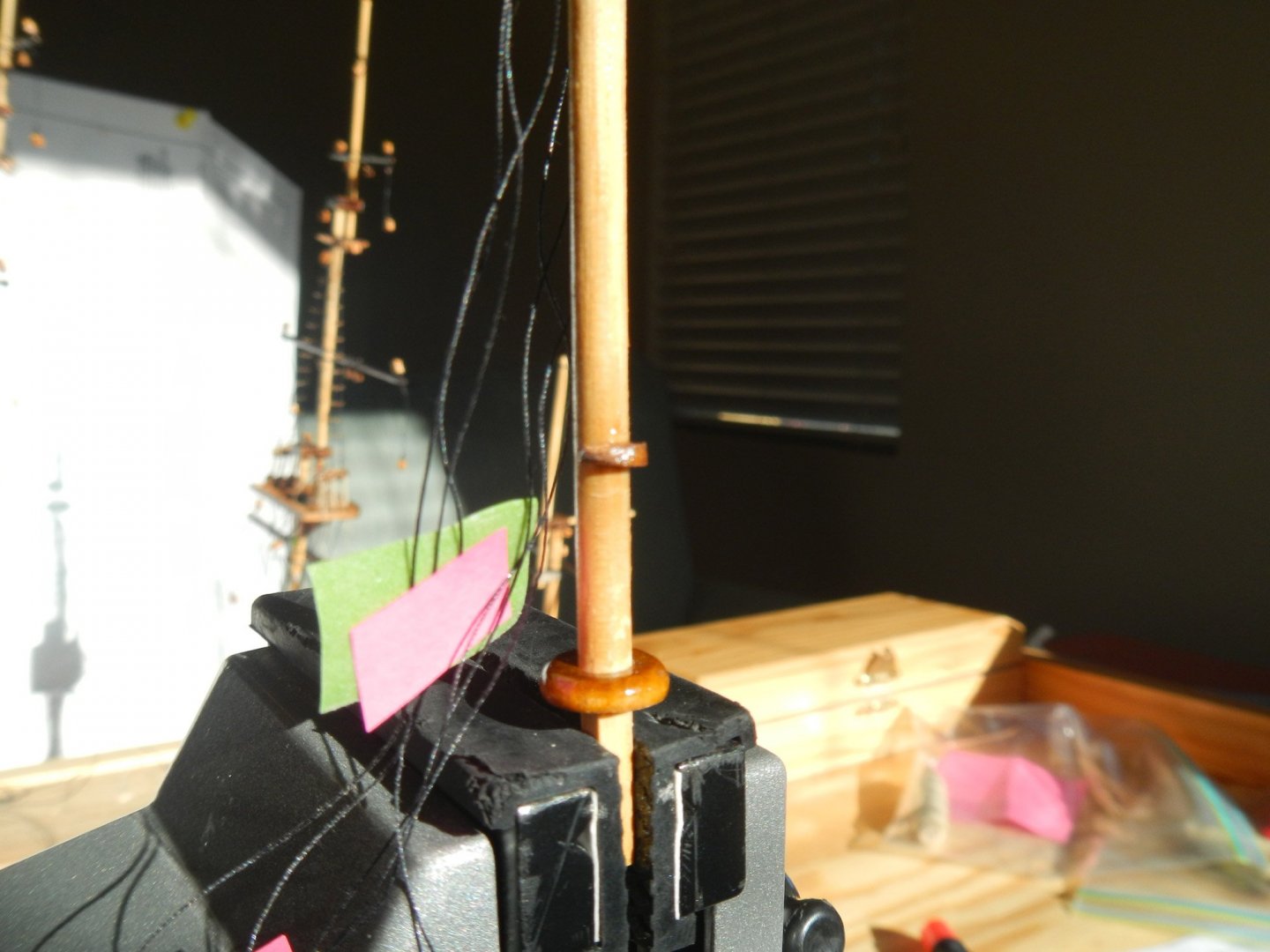
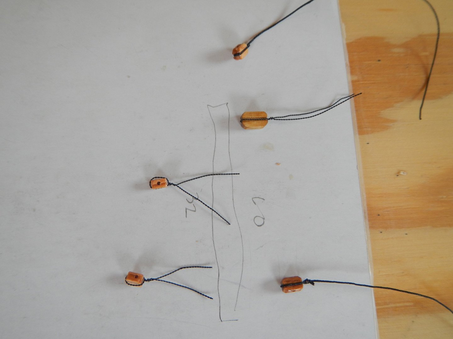
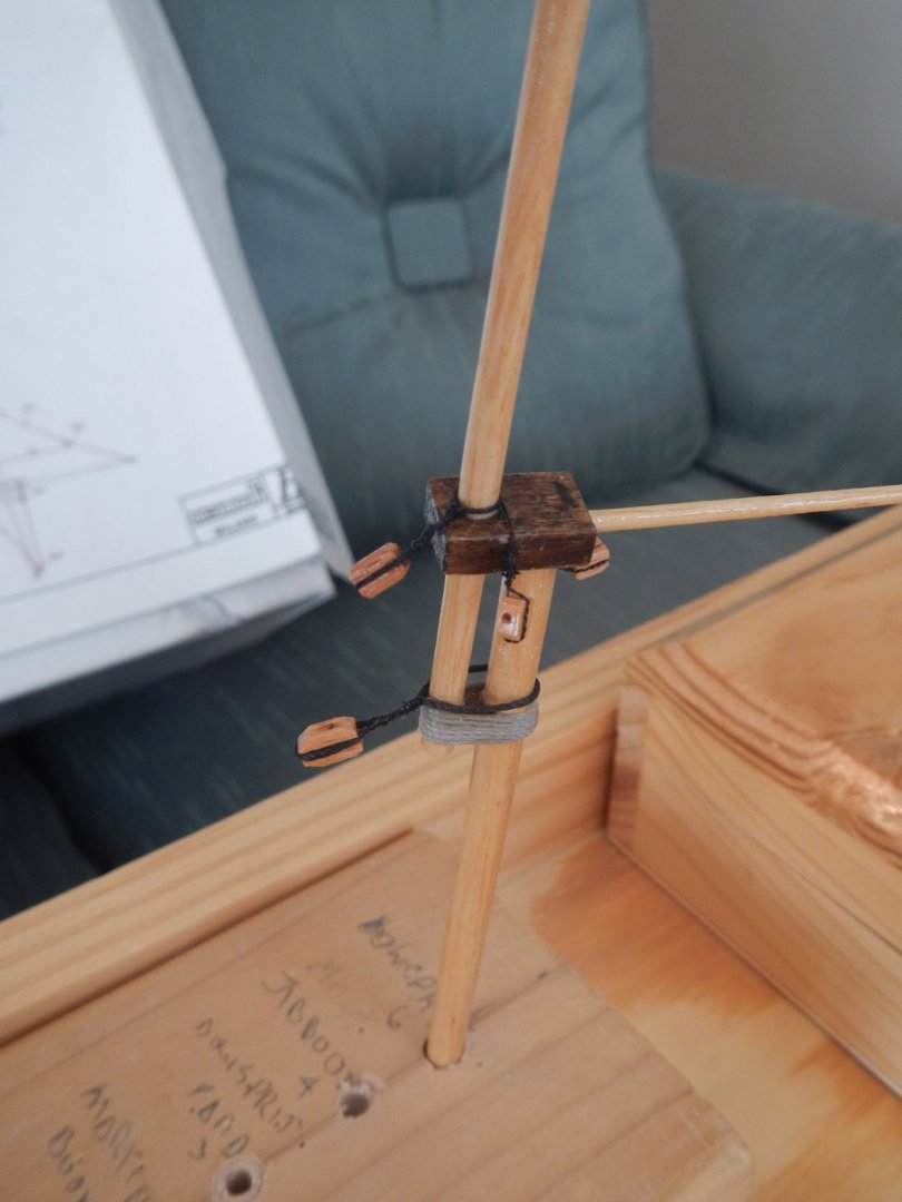
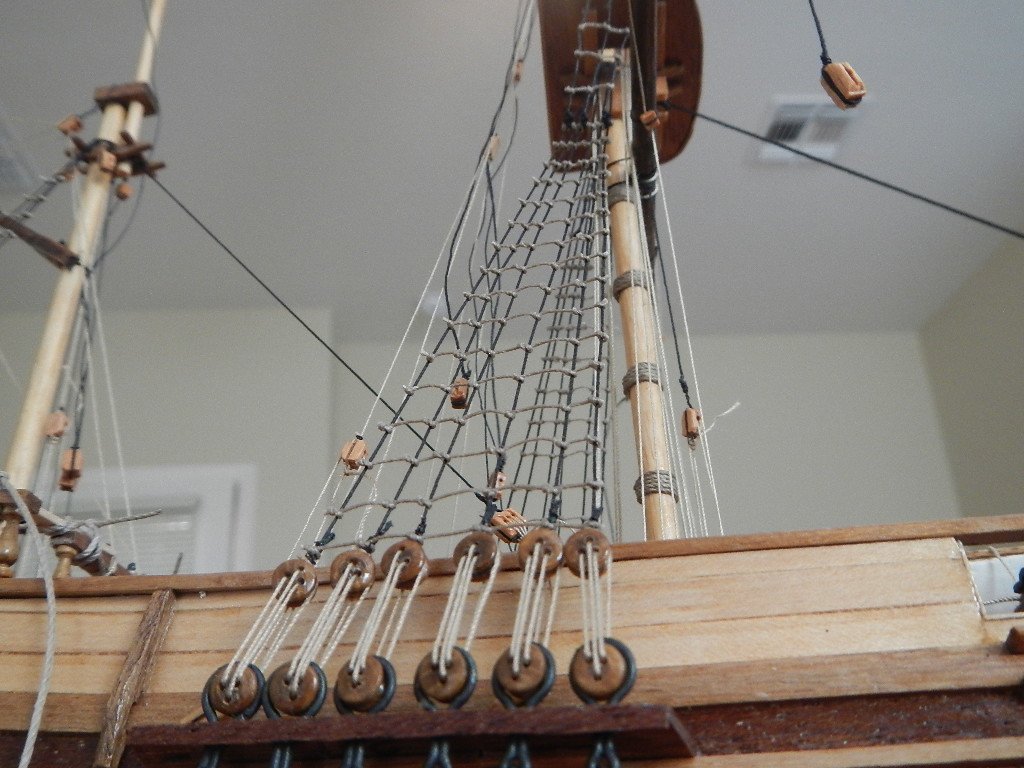
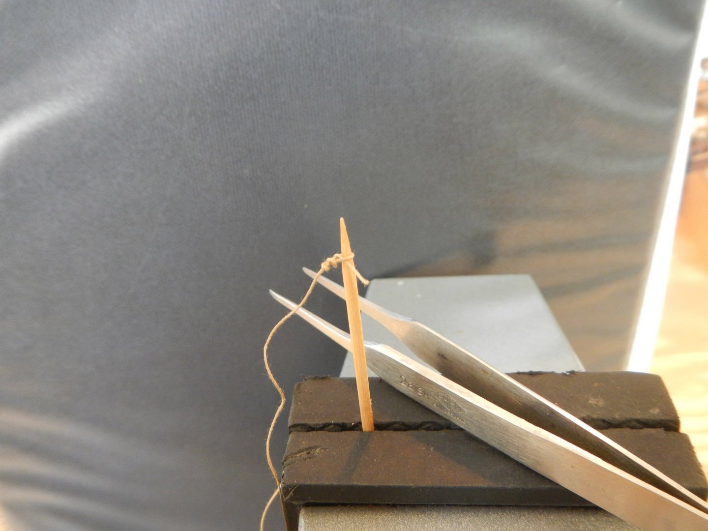
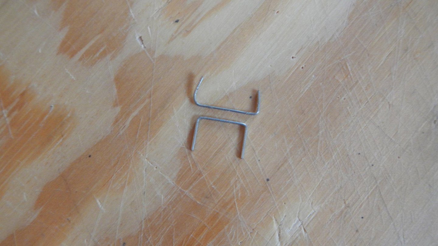
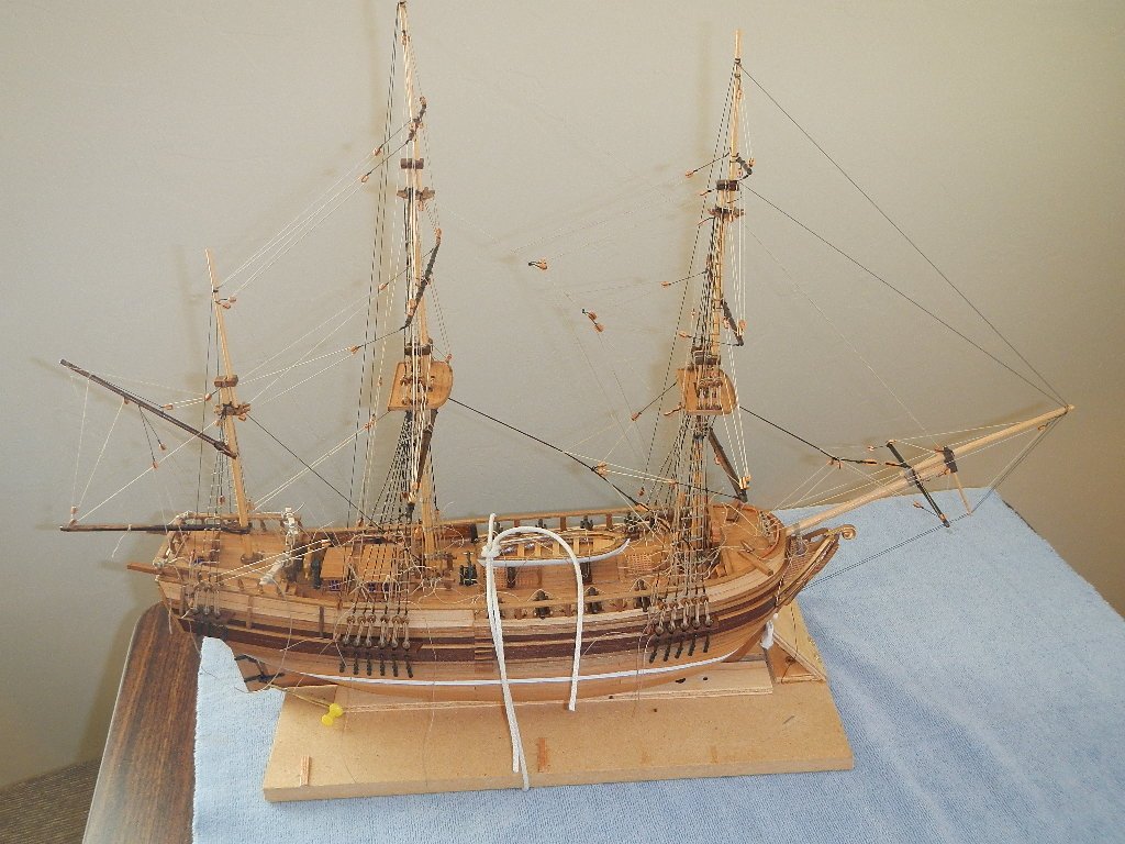
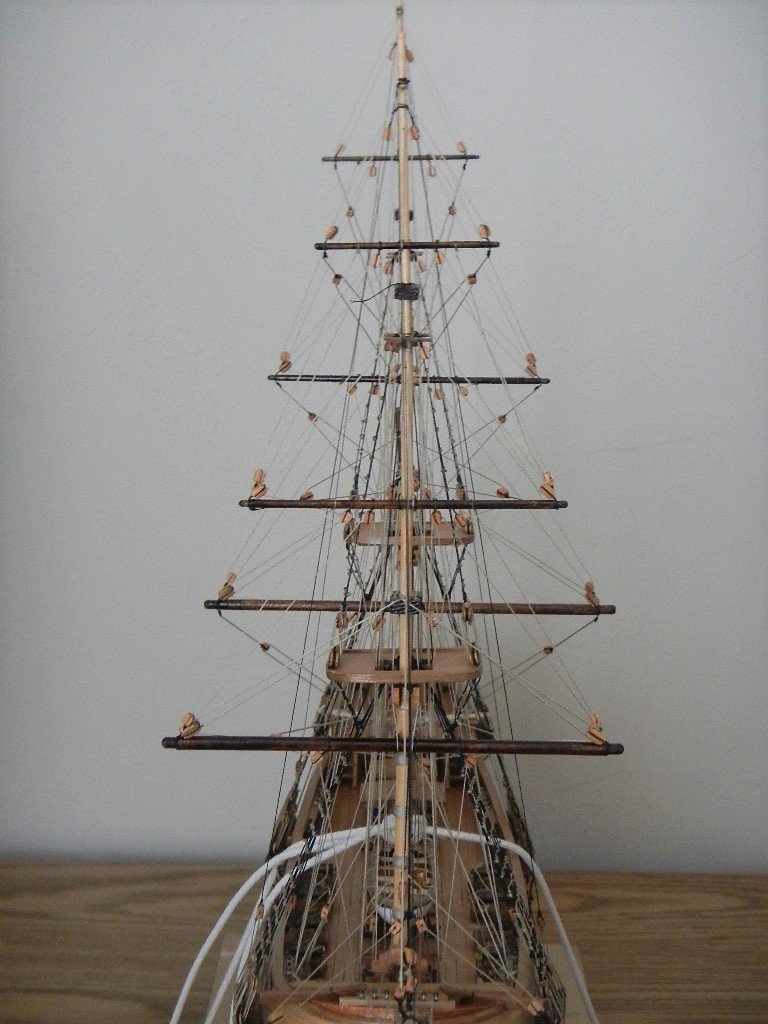
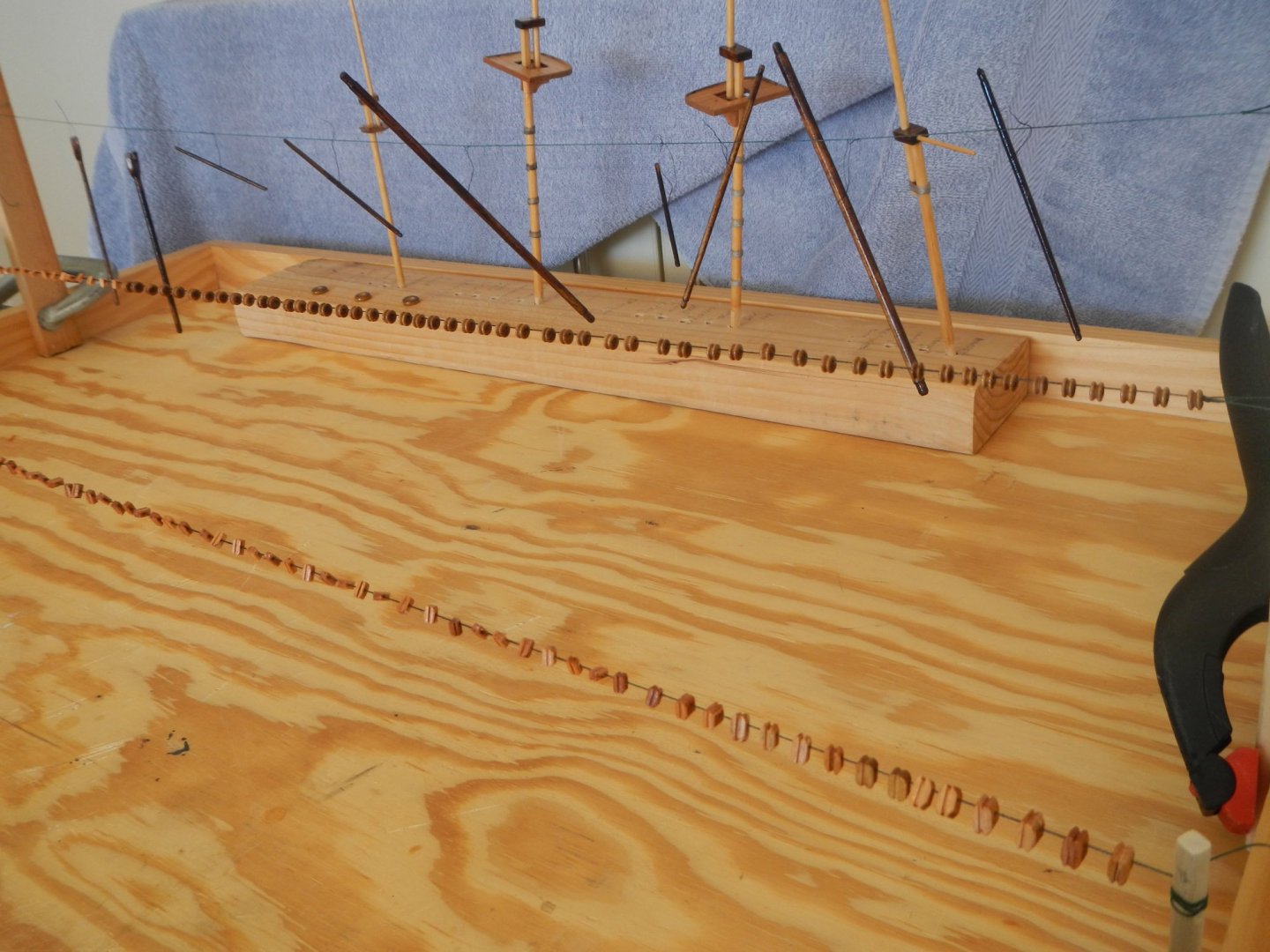
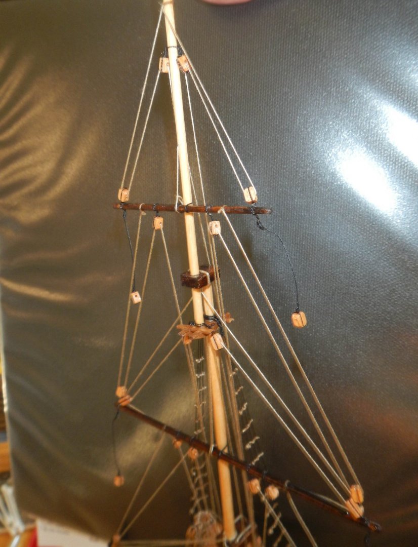
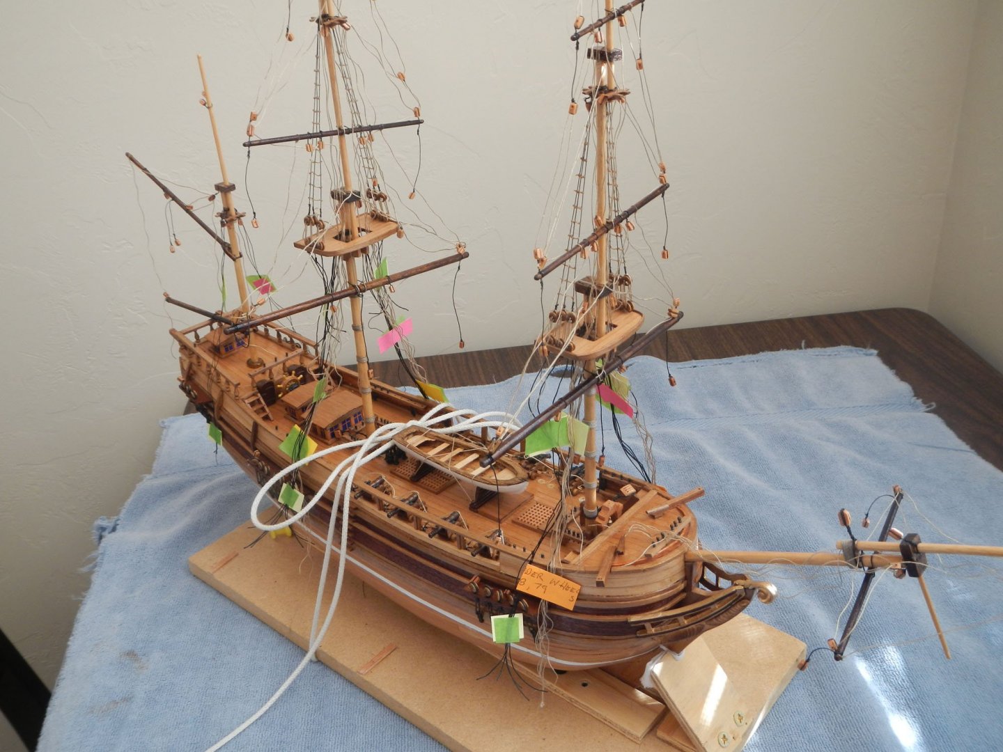
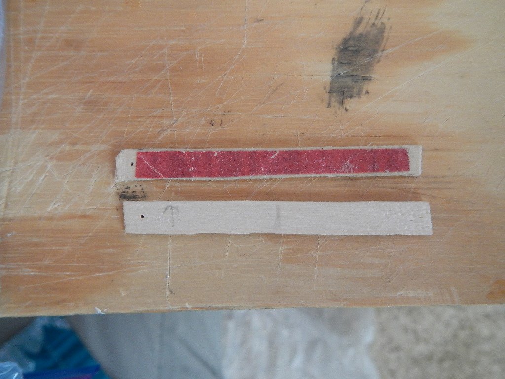
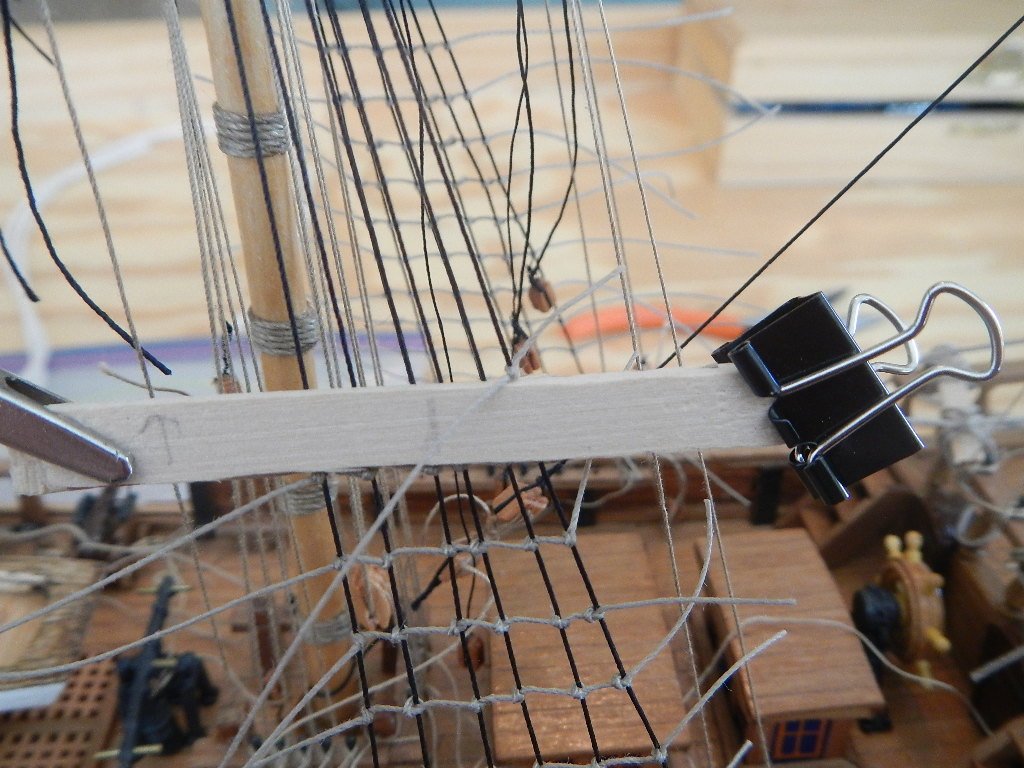
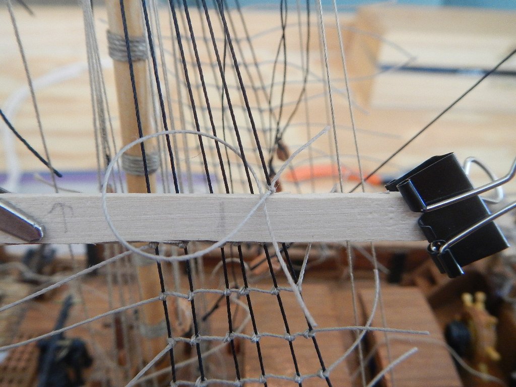
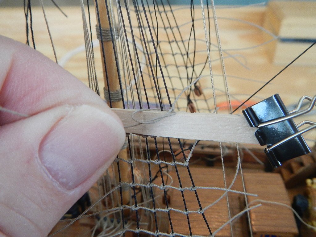
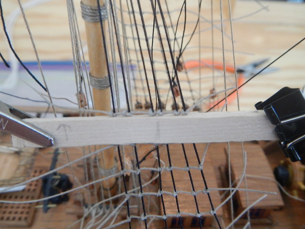
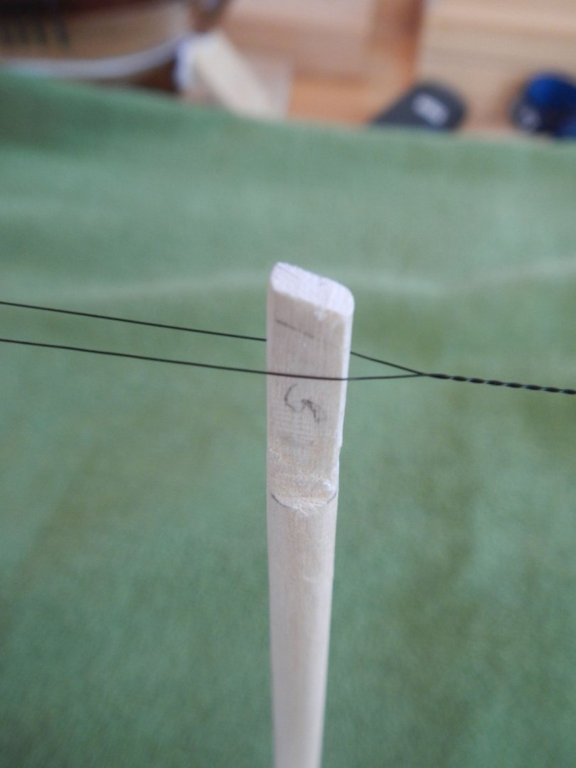
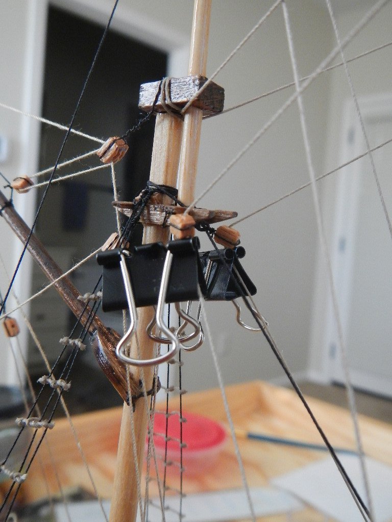
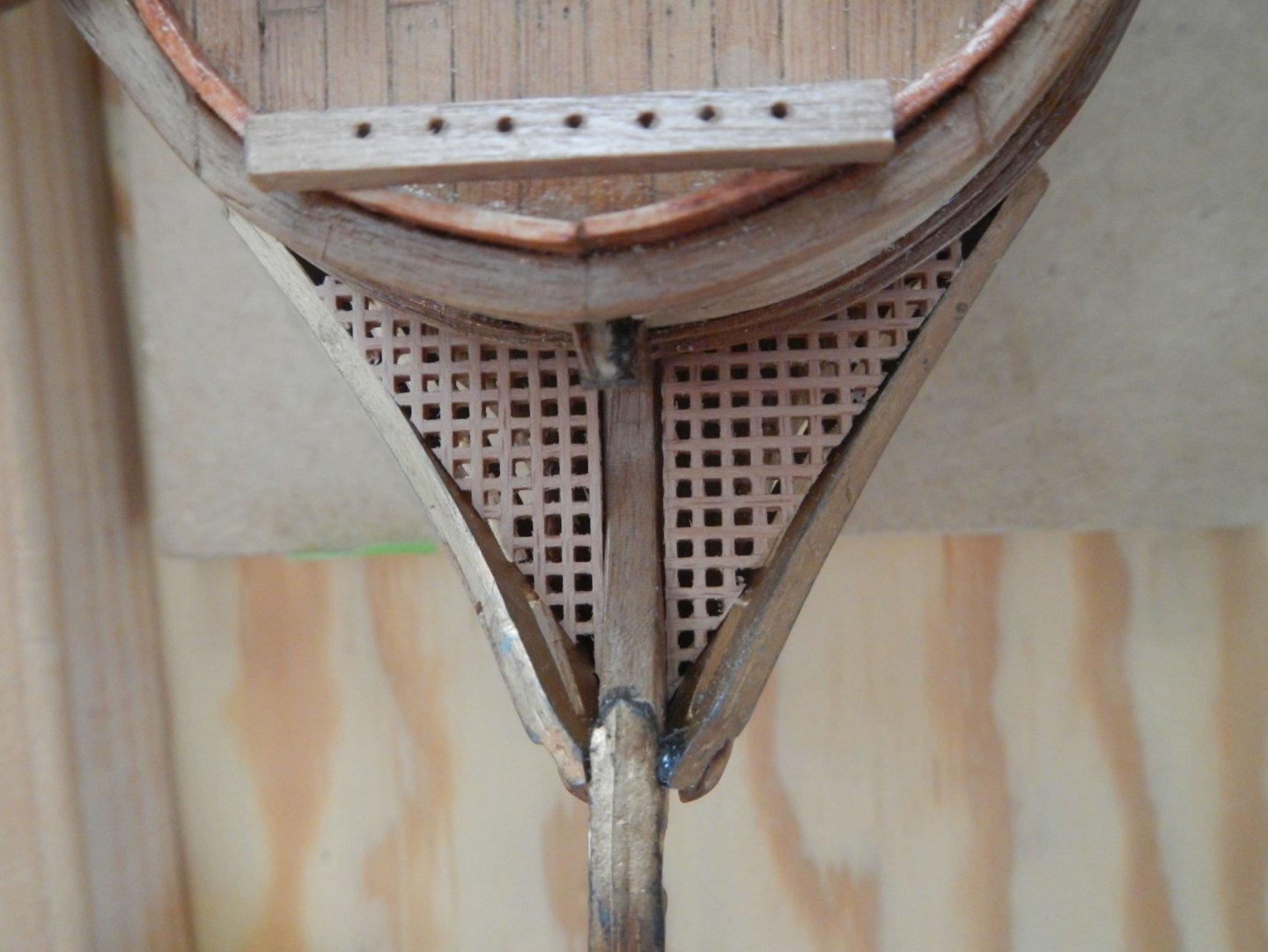
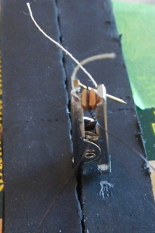
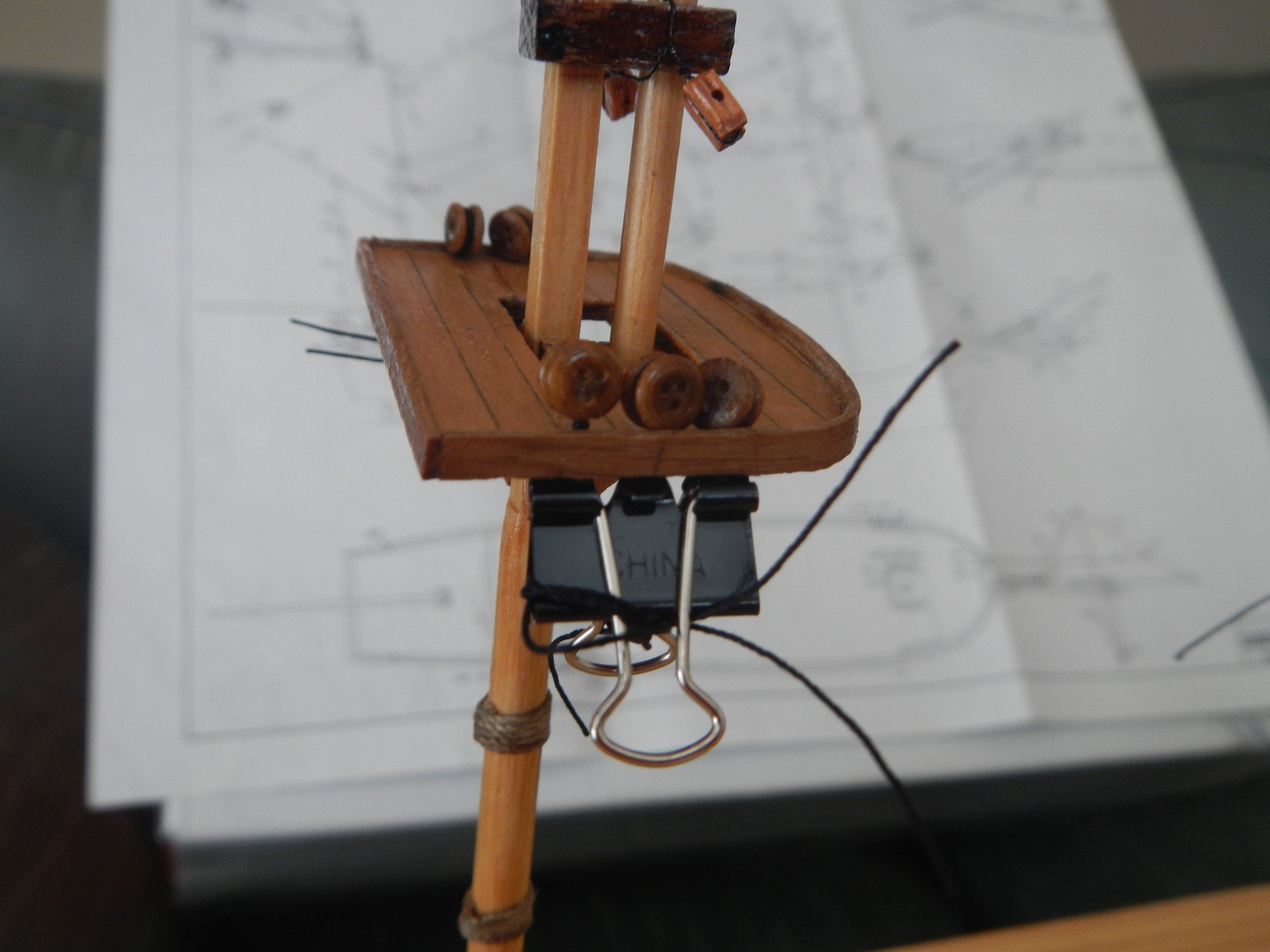
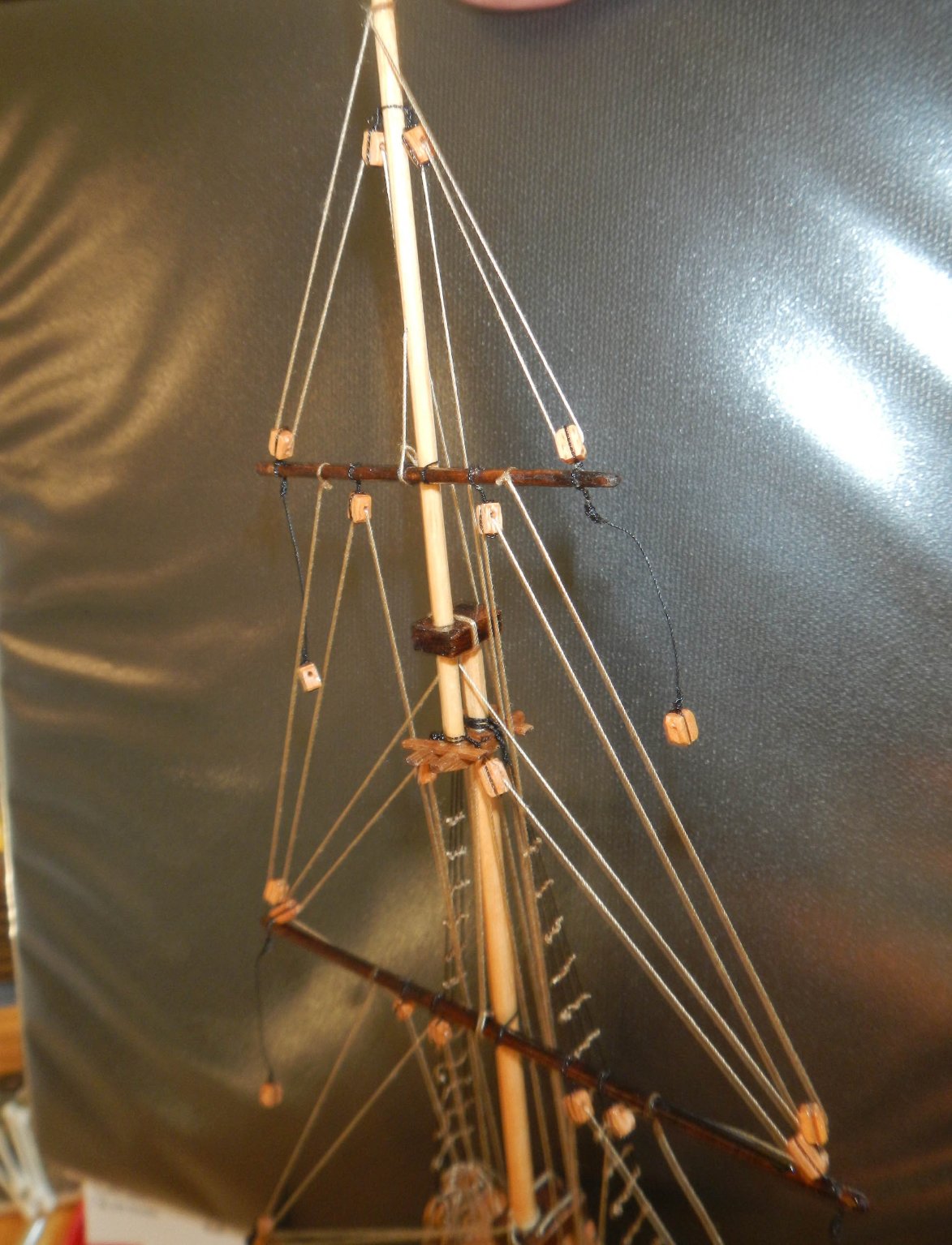
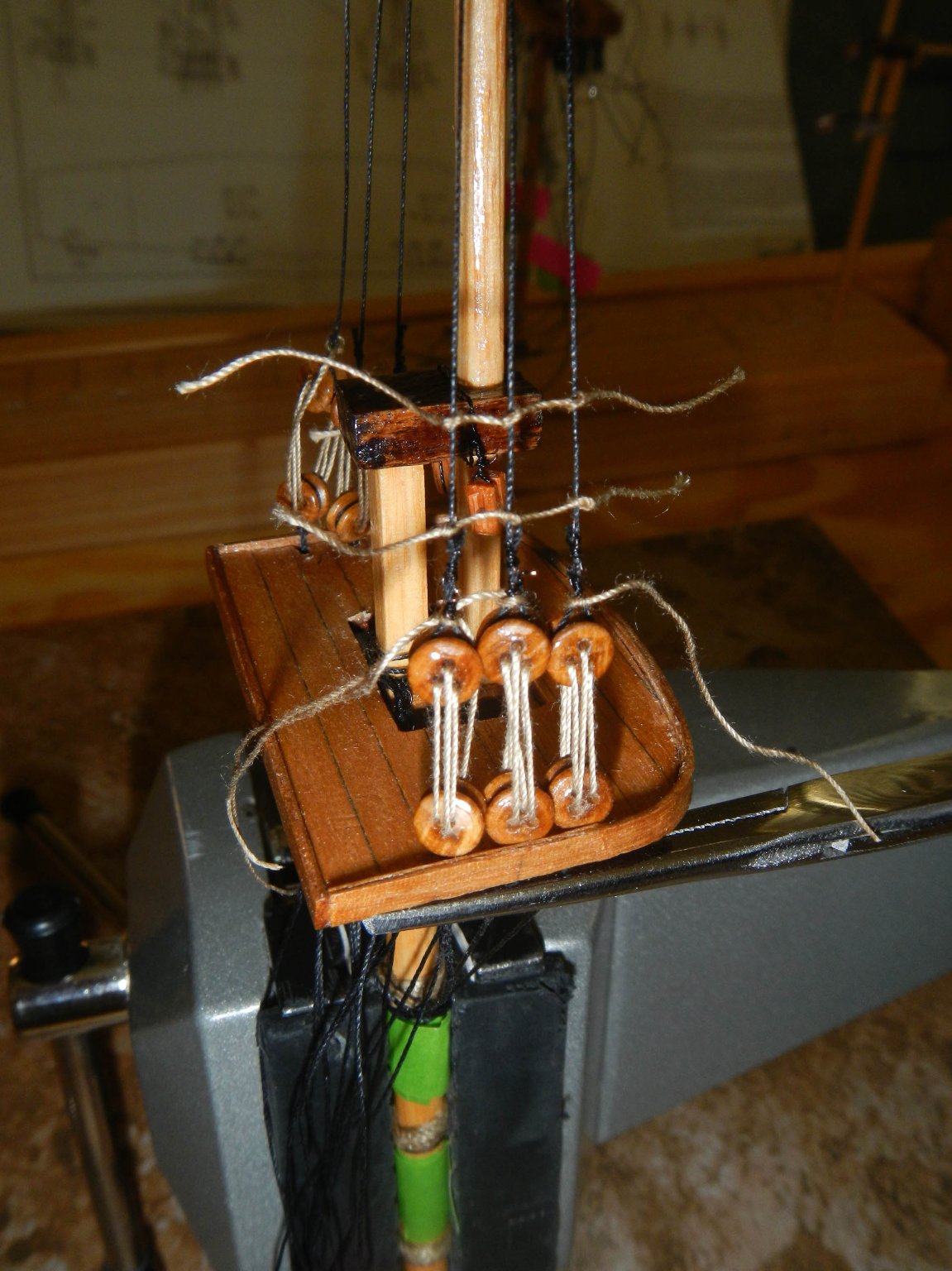
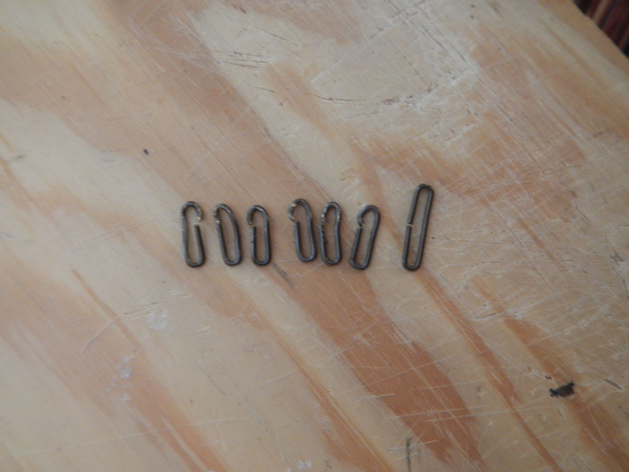
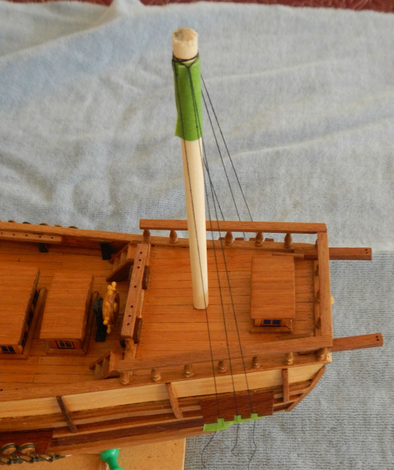
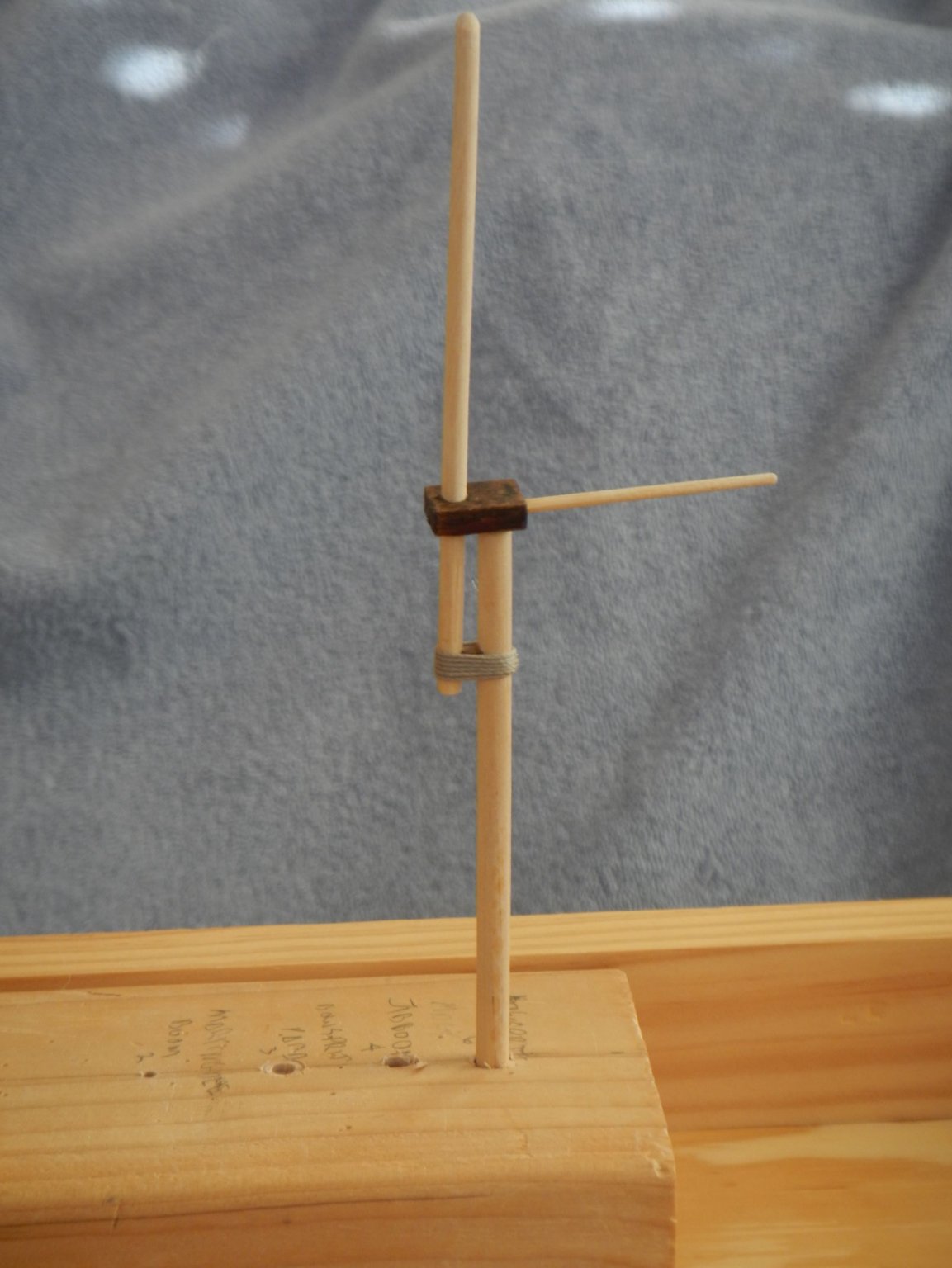
October 29, 2020 Rigging This build log entry covers the installation of rigging on the Beagle. Before starting the rigging, I put a finish on the masts, yards, booms and blocks. For the yards I chose to use a dark walnut stain. As I worked through the rigging, the aft railing came to harm a couple of times. I, therefore, decided to lash together the four corners of the railing to provide additional support until the rest of the ship is finished. They will be removed when the ship is complete. In doing the rigging I decided to follow the order defined in SMS, rather than the instructions provided in the kit. I found that doing a lot of the work on the masts and yards before stepping the mast through the deck made a lot of sense. Also, leaving the lower shrouds to almost the end made it a lot easier to belay the other lines on the interior of the deck. What follows is the order of work defined by SMS and my comments. 1) Fit masts (and hull) with blocks I rigged the blocks in one of two ways. For blocks that needed to be closely tied to a mast or mounted on a deck, I used two strands of #34 black annealed wire twisted together. I twisted about two feet at a time using a drill, vise and guide rod. For block that were on a line, such as a pendant, I seized the line using one strand of #343 wire in a standard seize wrap. Here is a picture with both types. And a picture of the bowsprit showing both. Here is the hull with blocks installed. 2) Rig futtock shrouds to masttops I originally tried clamping the futtock shrouds and deadeyes to the masttops or tying them to the masts, but I found that neither way stood up to reeving the upper shroud deadeyes to the futtock shroud deadeye or rattling down the upper shrouds. I ended up gluing the futtock shroud deadeyes to the masttop. Here is one unsuccessful attempt using clamps. 3) Rig lower shrouds to mast I seized the shrouds using a length of #34-gauge wire, similar to the blocks. To keep track of the lower shrouds, I coded them with pieces of twist tie from 0 to 3, 5 or 6, i.e. 0,1,10,11,100,101. 4) Rig topmast shrouds to topmasts 5) Fit ratlines to topmast shrouds Here is a partly completed ratline installation on the upper shrouds. There is more detail on ratline installation below. 6) Fit the yards with blocks and pendants I used the same techniques here as for the mast and hull. 7) Put the yards on the masts and rig the halyards and yard lifts It was much easier to rig these lines with the mast held in the vise, rather than trying to work with the mast installed through the deck. I did not glue any of the yards to the masts. I thought it would be more instructive working with the rigging if the yards could move. Here are the masts and yards with blocks and pendants 😎 Put the gaff and boom on the mast and rig lines for them Although not included in the instructions, I added a boom rest to the mizzenmast. Like the yards, I did not glue either of the booms to the mizzenmast. 9) Step the masts through the deck This step was pretty easy, as I had previously squared off and fitted each mast to its mast box in the hull, so alignment was built into the way the masts were constructed. Here is the ship with the masts stepped, included the bowsprit. 10) Belay the yard lifts and halyards I created a belaying tool by taking a piece of coax cable, stripping part of it down to the copper wire, flattening the wire, then drilling a hole in the end. This allowed me to push the line under the belay rack to wrap around the lower part of the belay pin. Tip: If the line goes around the upper belay pin clockwise, then the line needs to be turned counter-clockwise to get the line underneath to finish the belay (and vice versa). When you’re doing this on a boat it is easy, but when you are staring through a number of other lines while trying to belay with two tweezers in a tight location, it is not. Here is the upper part of the mainmast rigging. 11) Bend standing rigging in this order – Foremast stay to bowsprit, all mizzenmast gaff and boom rigging, mainmast stay to foremast and Mizzenmast stay to mainmast To create the loop needed for stays, halyards etc., I wrapped the line around a toothpick, then tied it with two half hitches. The stays were created and installed on the masts in step 1, then connected here. 12) Rig the lower shrouds to their lanyards and fit ratlines to lower shrouds SMS suggested a single deadeye gauge in the outer holes of the deadeye, but I found this too unstable when trying the seize the line around the upper deadeye. So I created two gauges from staples (widen to the correct length for deadeye separation). (Gauge next to original staple) I placed these in the four inner holes of the deadeye and locked them in with a alligator clip attached to one of the gauges. To install the ratlines, I used a ratline tension tool (suggested on the masts, rigging and sails forum -- https://modelshipworld.com/topic/14818-rat-line-tension-tool/?tab=comments#comment-460820. I put sandpaper on the inside of one of the pieces to help hold the shrouds in place. I hadn’t really seen any good details on how to approach tying the ratlines. Even SMS was somewhat vague on the details. So, I have enclosed my own little tutorial showing the technique I (finally!) found most effective (assumes that the overhand knots are being tied left over right.): a) Tie the first knot on the rightmost shroud. b) Run the line in front of then behind the next shroud, bring it out underneath the line. c) Finish the overhand knot and tighten pulling on the line while pushing the knot against the shroud with tweezers (not shown as I do not have three hands!). If you wanted to work left to right (for instance if you are right handed), I think the same process would work if you tied the overhand knots right over left. Here is the complete ratline run. To ensure that the starboard and port ratlines were at the same level, I measured down from the masttop for each ratline on the starboard side, then duplicate the same distance on the port side. Here are the completed starboard side foremast shrouds with ratlines. 13) Rig the backstays 14) Fit and belay all yard braces I found that installing the yard braces from the top down work better, because the topgallant yard braces are inside the topsail yard braces which are inside the mainsail yard braces. When trying to balance the yard braces during installation, I found it helpful to clamp the line at the blocks on the mast to maintain the proper tension so that the yard remained perpendicular to the keel of the hull. I found that when I started trying to belay the bowsprit yard braces, that the bow belay rack, installed according to the instructions, didn’t allow for the last belay pin to be used, plus the anchoring to the thin strip of wood was too weak. I, therefore, moved back the belay pin rack, drilled two holes through the rack into the deck and added two brads that were glued to the rack and the deck. This worked fine. Here you can also see the bow crosshatching that was installed after the bowsprit woold was completed. Here is the completed rigging – starboard view … and bow view Build time to date – 584 hrs: 149.75 hrs for the work in this build log entry. Next: Finishing Kit Note: I had to purchase additional line to supplement what was in the kit. I bought additional .8mm line, black .4mm line for standing rigging, black .25 mm line for standing rigging and tan .25mm line for running rigging. I ran out of the last as I was preparing to rattle down the lower shrouds. For the .8mm standing rigging I dyed some of the line with a black magic marker. Fun facts: 42% of the time was in installing the shrouds and ratlines (it seemed longer than that!). It took 582 overhand knots (tied with two tweezers!) to install the ratlines on the upper and lower shrouds. SMS – Ship Modeling Simplified by Frank Mastini


-
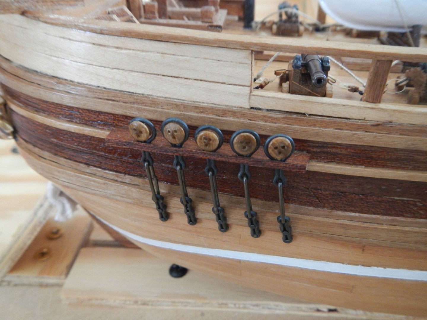
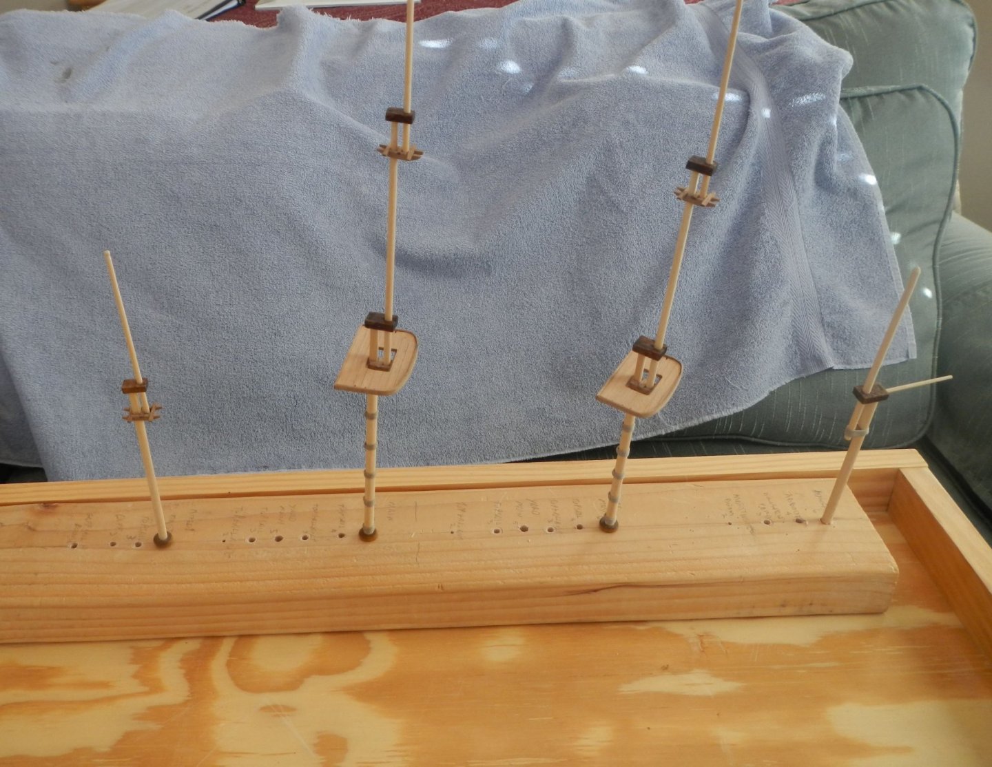
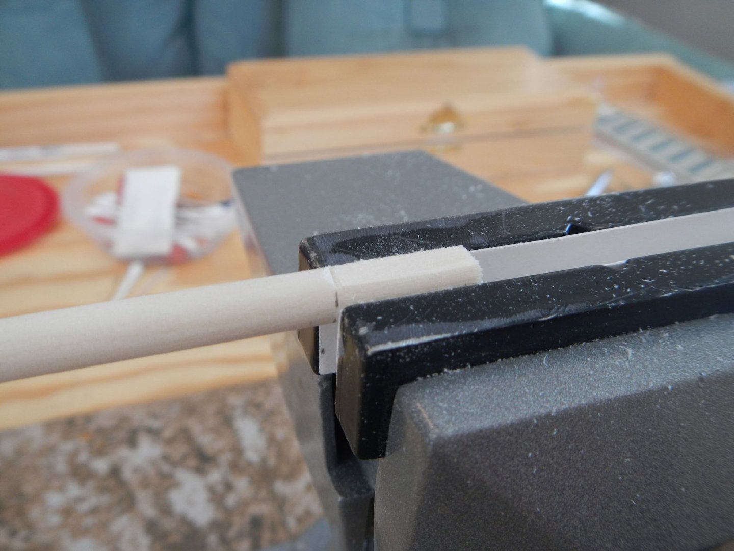
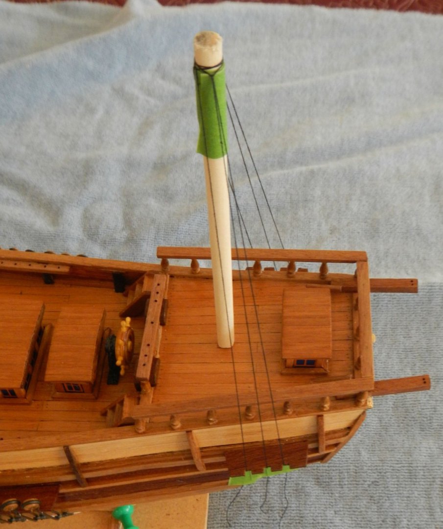
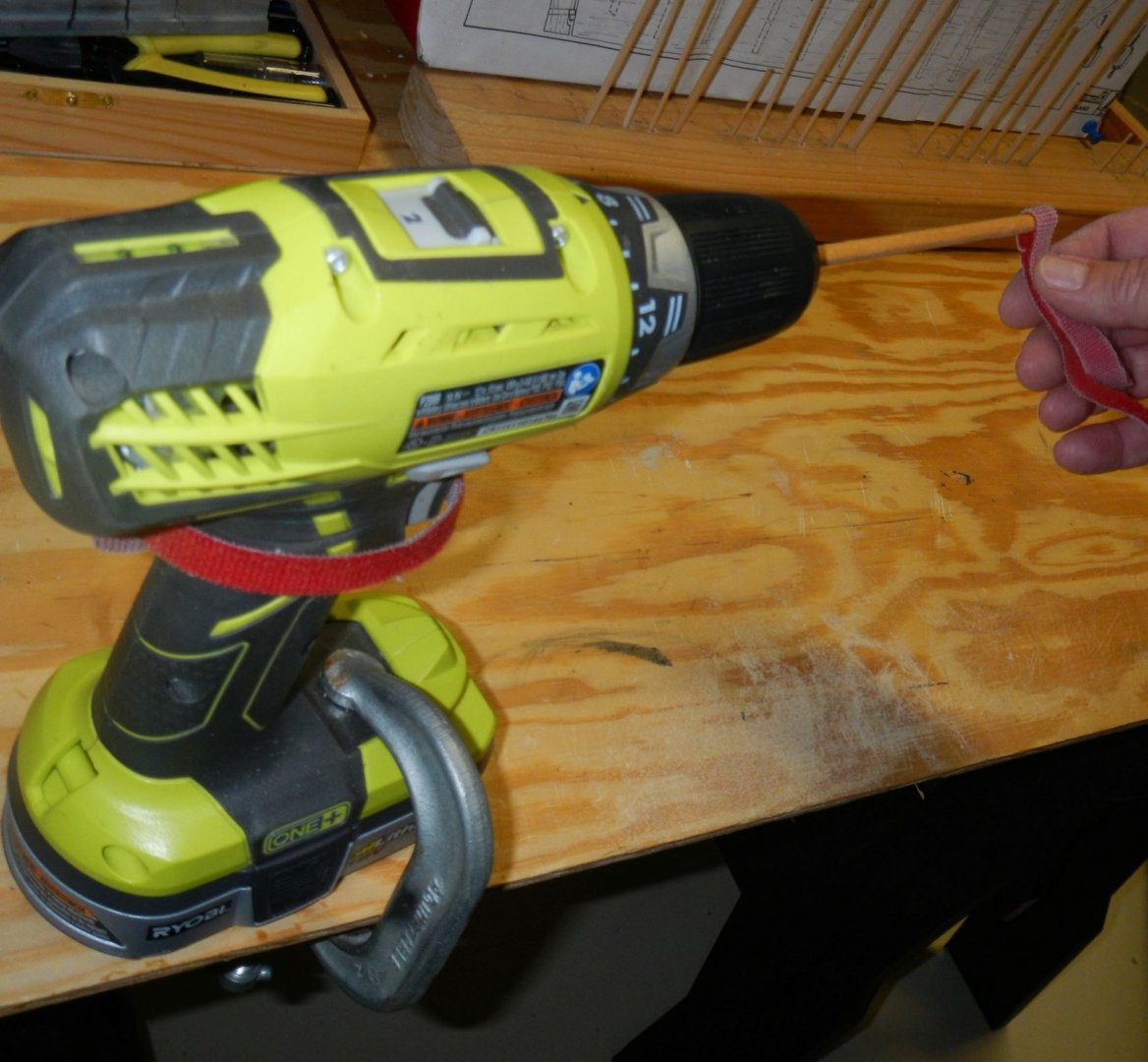
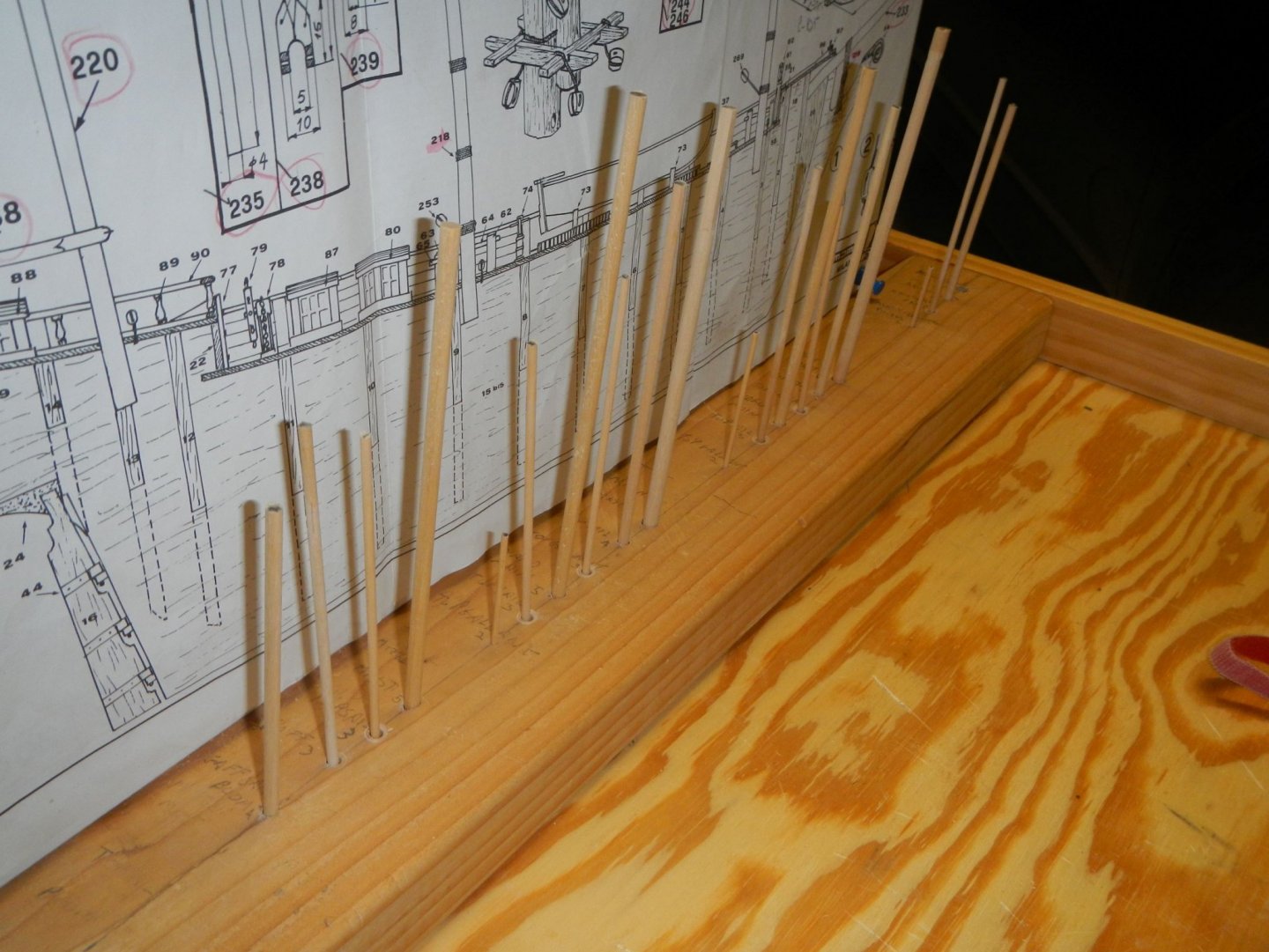
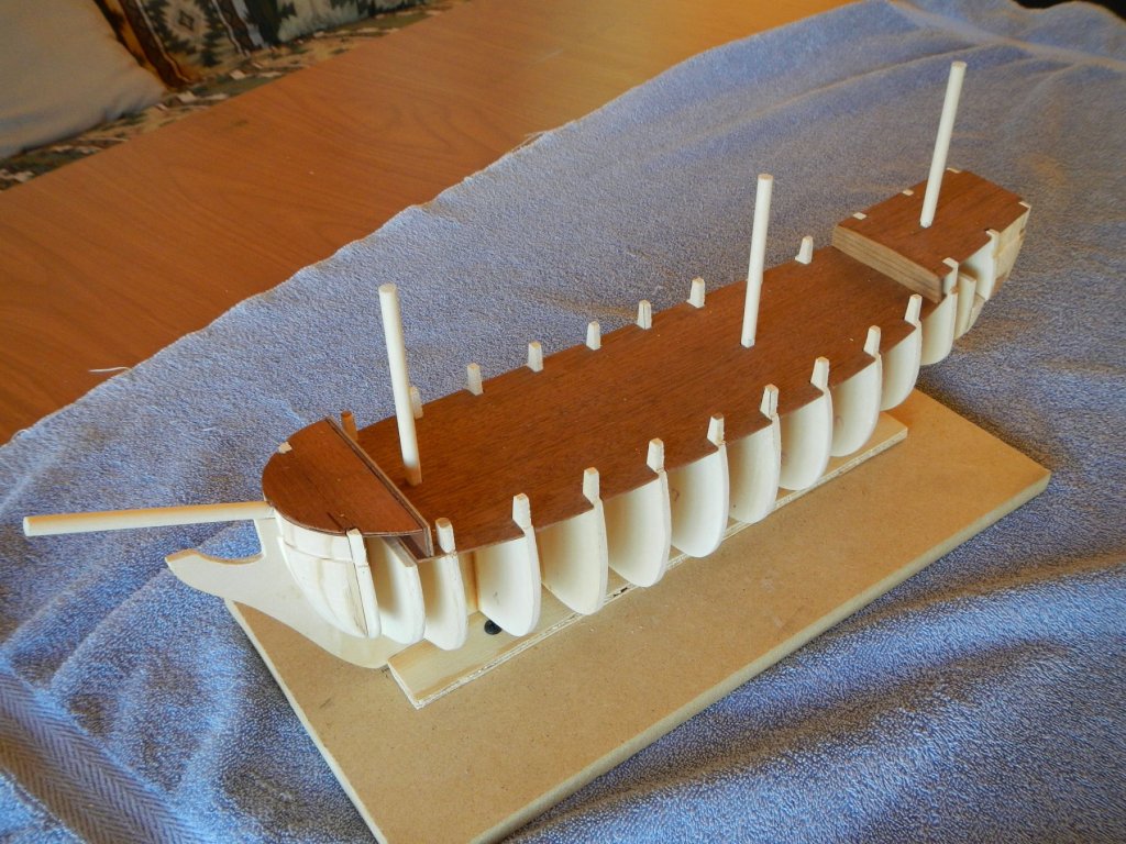
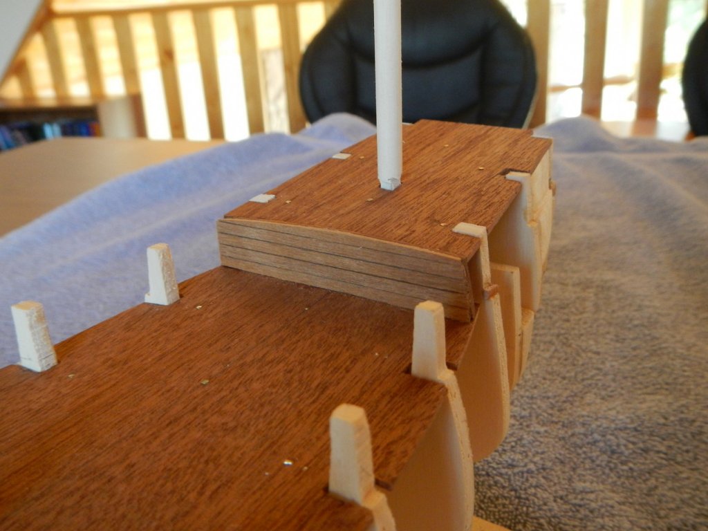
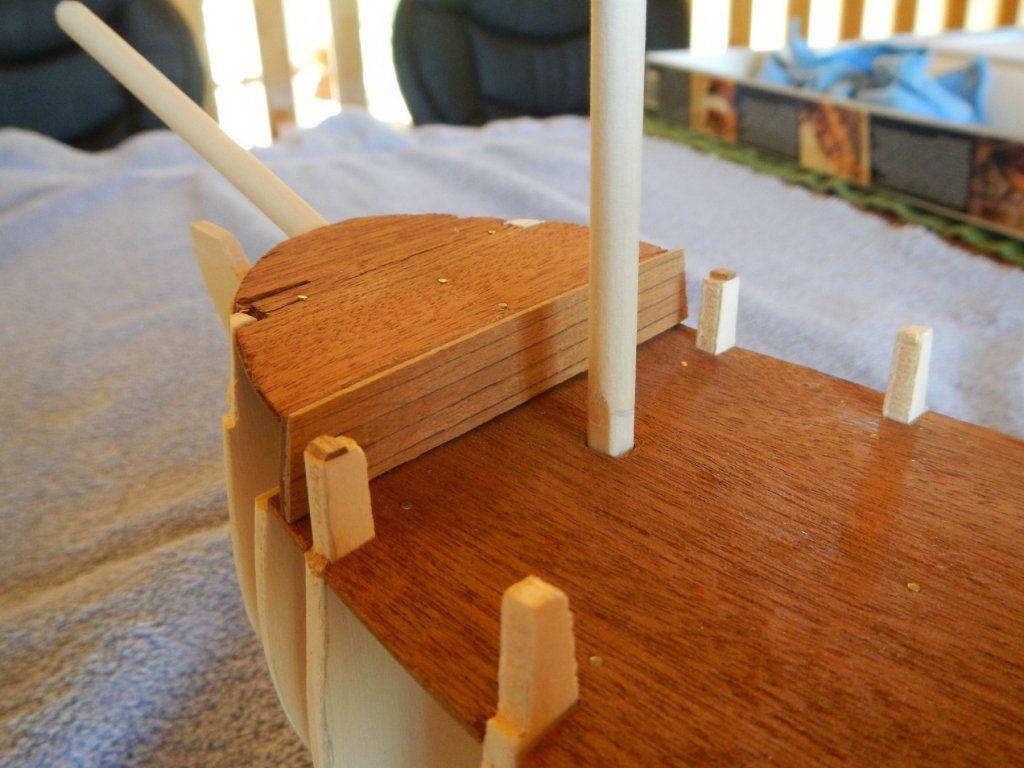
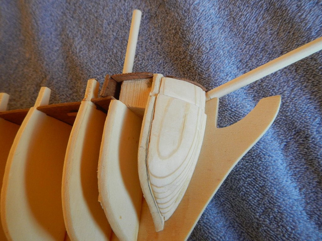
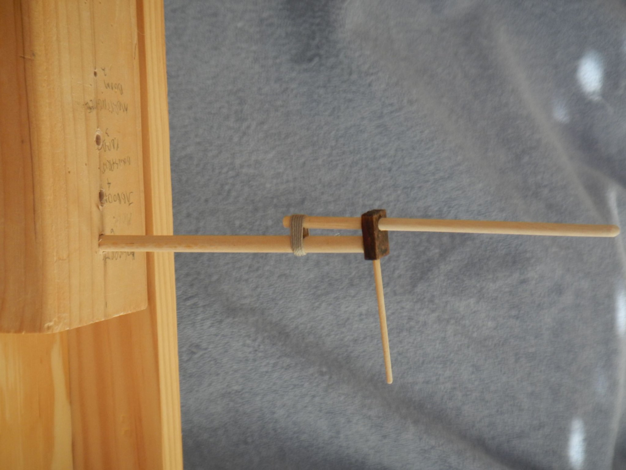
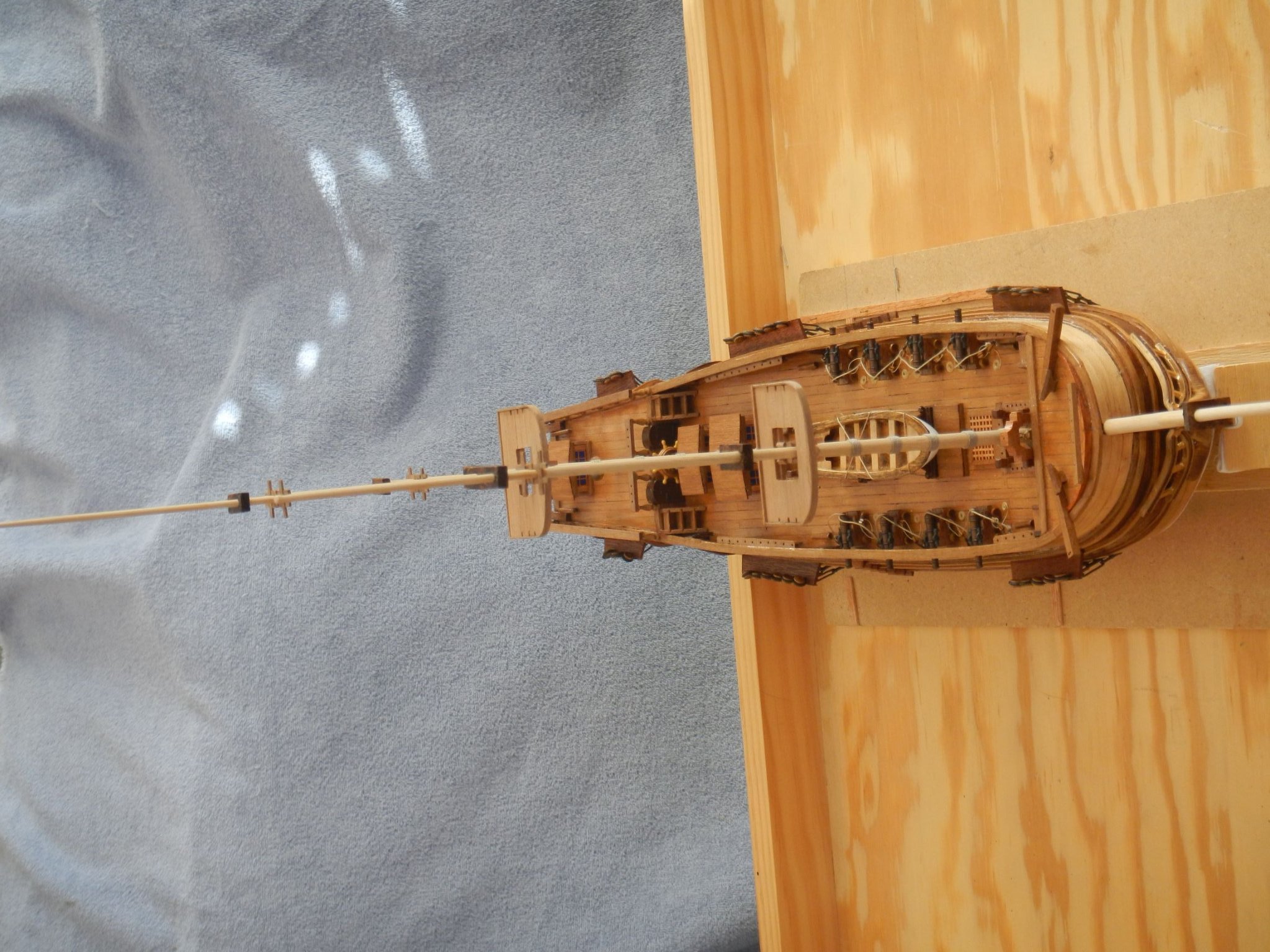
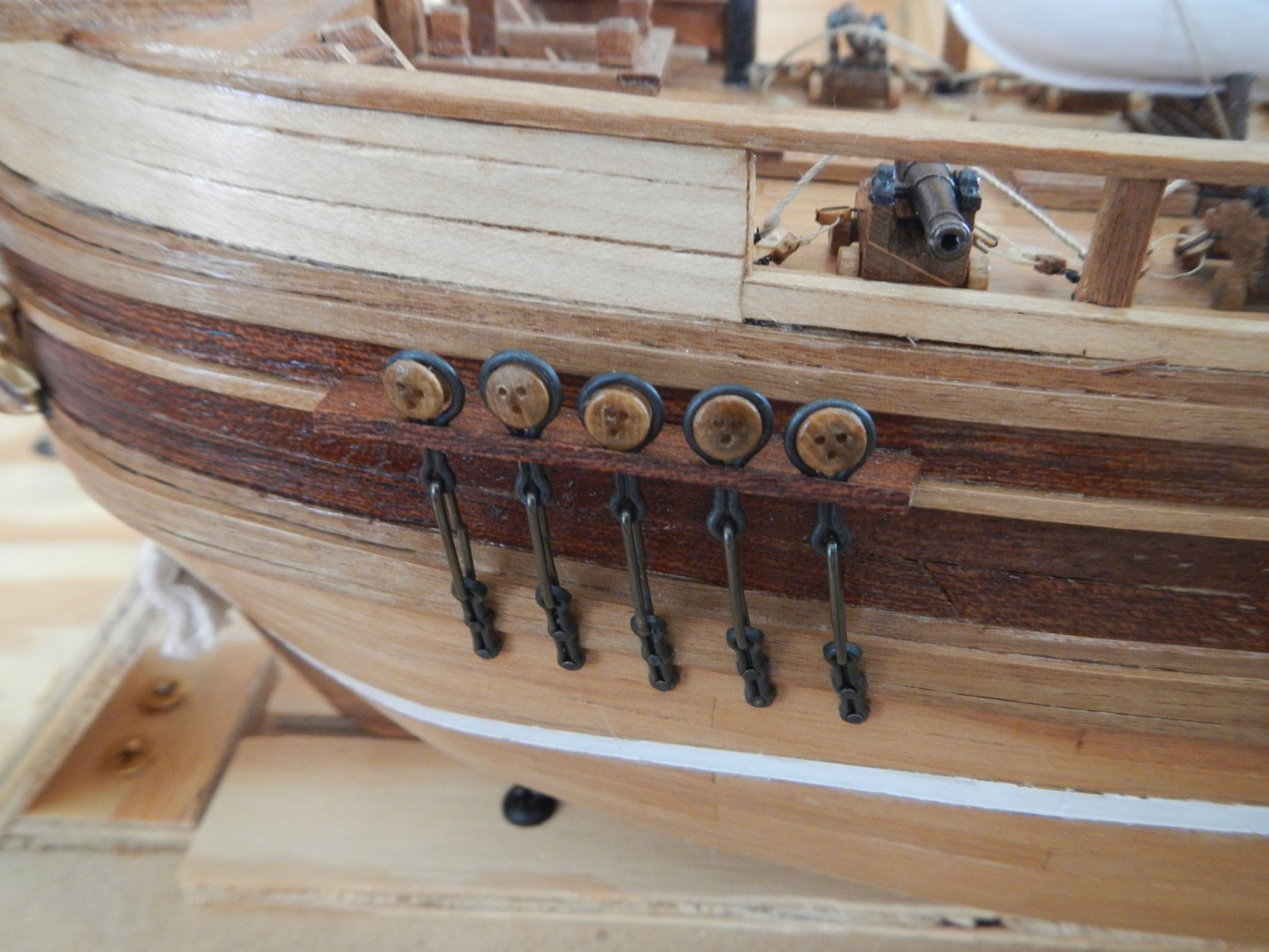
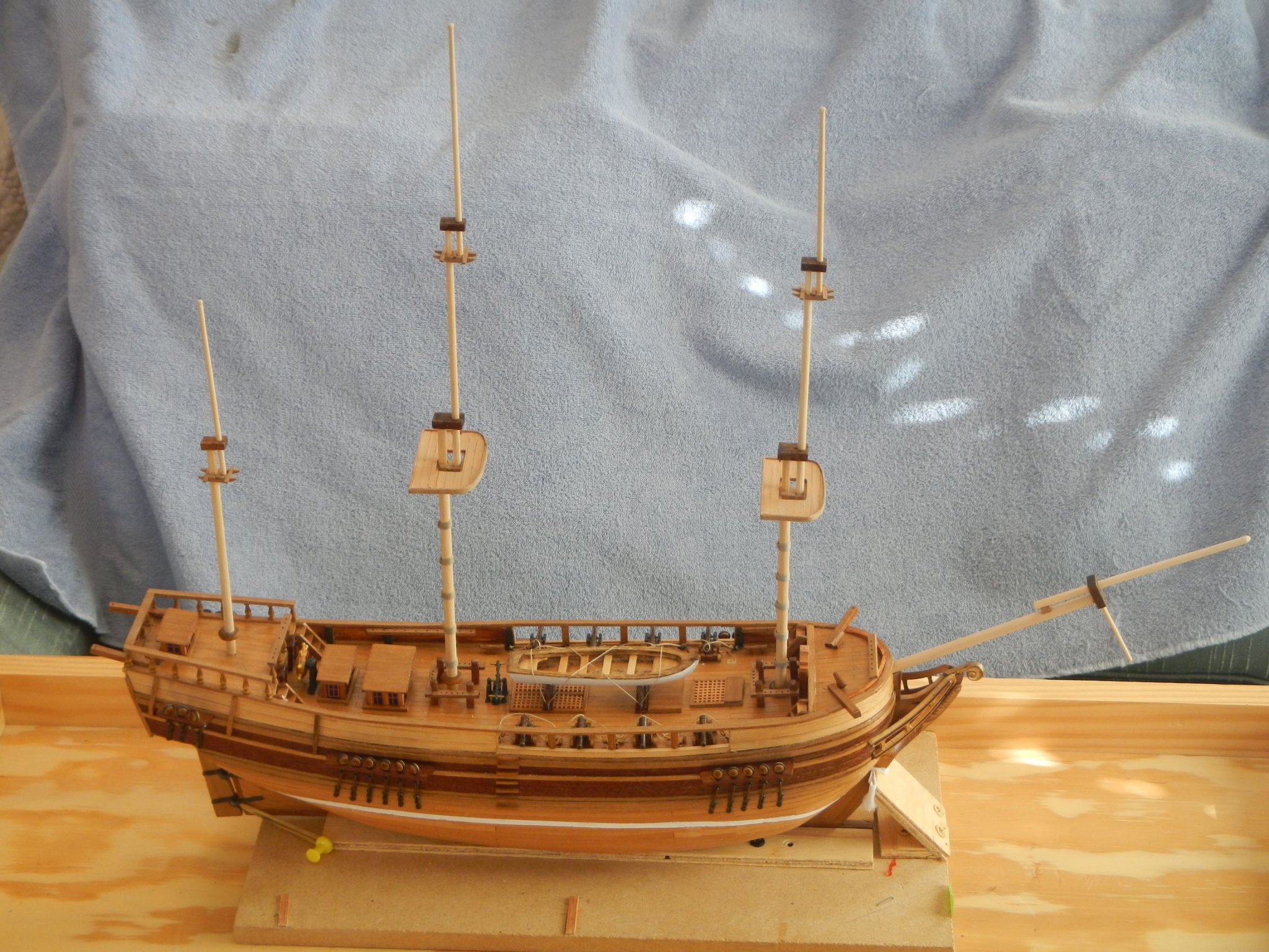
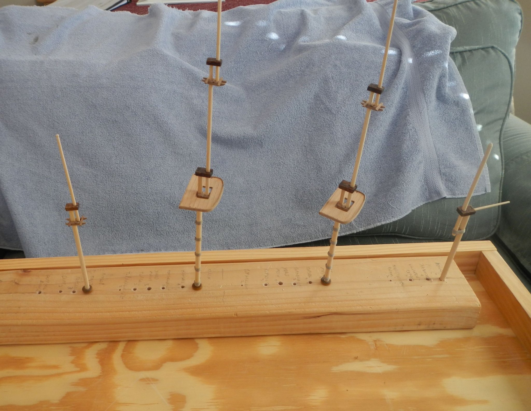
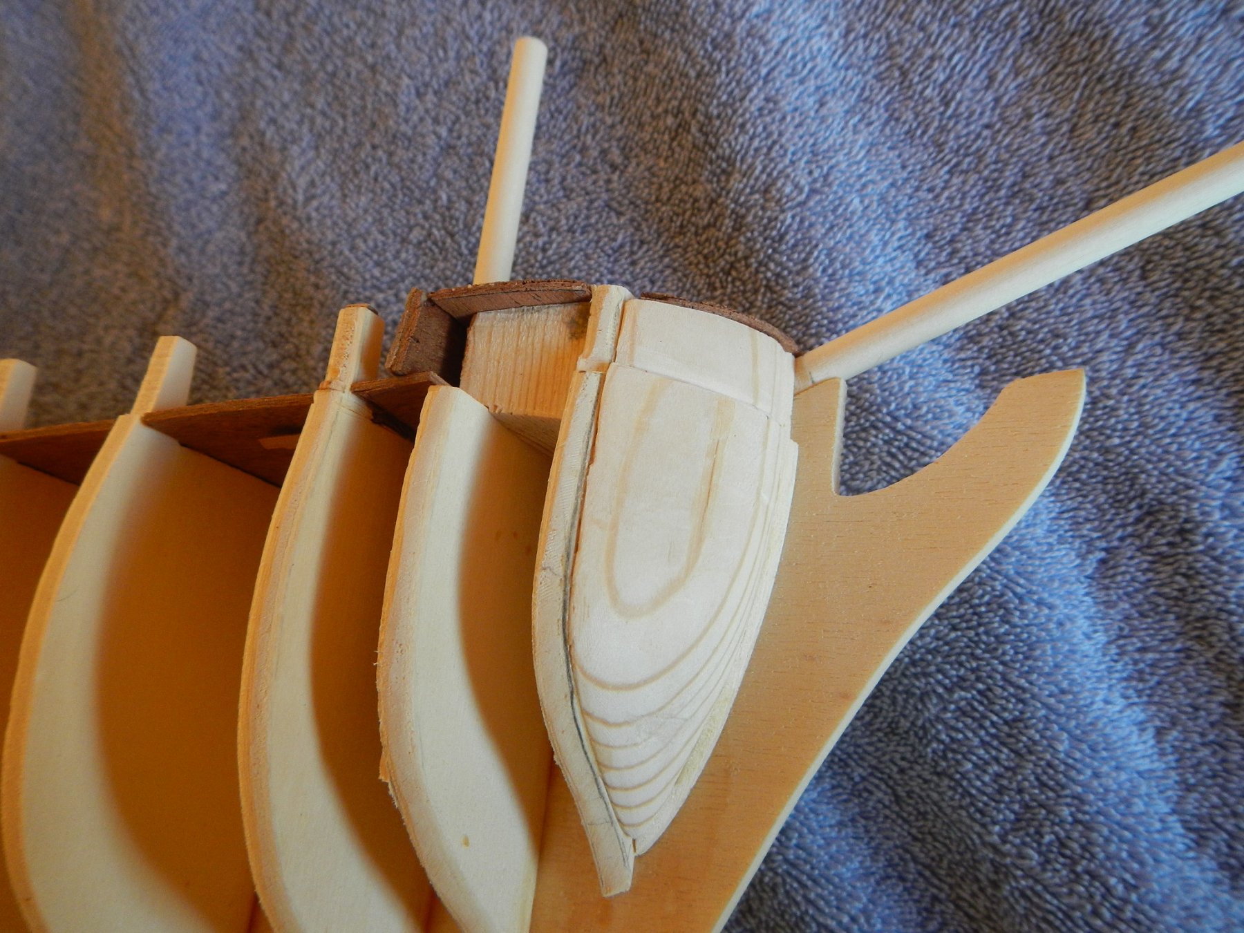
January 18, 2020 Masts & Yards This build log entry covers the preparation of the masts and yards and assembly of the masts. However, before I started on that there were a few items remaining to be done on the hull. The shroud supports had been glued to the hull, and now the deadeyes had to be installed. This is when I found out that the shroud supports for the foremast and mainmast were not symmetrical (see 3rd picture below). The deadeye slots were closer to one end than the other, and the way they were manufactured and labeled caused them to be offset differently on each side of the ship. I tried to compensate for that (as well as even out the spacing) when I widened the precut slots to accommodate the deadeye holder. Note: The metal parts in this kit have no deformation capability; they just break. I found this out trying to bend the deadeye holder around the deadeye as indicated in the instructions. To properly align the deadeyes to the shroud lines coming down from the mast, I construct substitute masts of the correct height, then ran thread down to each deadeye slot, so that I could determine the proper angle to put on the deadeye link when mounting it to the hull. This was suggested in SMS. For the mizzen mast deadeyes, I found that the provided deadeye links were too long for the hull that is available at the stern, so I shortened and re-bent the link to fit the available space (this is the only metal that is pliable). After installing the deadeyes, I covered the edge of the shroud support with a piece of mahogany lath, which seem to blend very well with the shroud support wood. The second item was crosshatching in the bow. It is shown in one of the instructions, and the material is provided for it, but there is no mention of adding it in the instructions. To fit the material in the bow space, I created poster board templates for the port and starboard sides to give me a starting point for cutting out the crosshatching. I then put together a grid of laths to accommodate the templates, cut out the pieces, and sanded them until they fit into the bow area. These will be installed after the bowsprit woold is completed. Now that I was ready to start on mast construction, I started by building the masttops and crosstrees for each mast. Although not indicated by the instructions, I added a chock between each mast for all the masttops and crosstrees, as suggested by SMS. I believed this would aid in aligning and securing the masts during assembly. For the main and fore mast masttops, I added bolsters, also suggested by SMS, to protect the shroud lines extending down from the masts. I then proceeded with cutting and shaping the masts and yards. I drilled holes in a 2x4 and labeled each hold with the respective mast or yard putting them in order from stern to bow. I cut out all the masts and yards from the supplied material leaving excess material to be used to handle the wood through the shaping process. I shaped the masts and yards as needed by setting up a homemade lathe using my electric drill (another SMS suggestion) with a loop of Velcro (felt side) to hold the other end of the wood. The other piece of Velcro was over the trigger to keep the drill on. As I mentioned previously, I had built square mast boxes in the hull for the three masts, so I now needed to square up the masts to fit into those boxes. I did that by placing the mast into the vice, leveling both, then filing down each side of the mast – another MSS suggestion. I did the filing iteratively with testing the fit into the hole until I achieved a tight fit. I then labeled the side of the mast facing the bow, so that I could build the rest of the mast segments on top facing in the correct direction. I used the same process to square the tops of the masts. The mizzen mast boom and gaff required yokes, which again were indicated but no material was provided. So I fashioned the yokes out of a bit of oak by drilling the mast hole, then cutting the yoke out using the hole as the base. In addition, I drilled a hole in the bowsprit mastcap for the martingale. The yards, booms and mastcaps were supposed to be either dark walnut (instructions) or black (paint diagram). I chose to go with the former. The last thing to add was the mast woolds on the main and fore masts (see picture below). Here the amount of 0.8mm hemp rope was completely inadequate to do the woolds, no less that other uses for that diameter on the ship, so I had to order some additional rigging line. Now that I was ready to assemble the masts, I first ensured that the workbench was level. Since the masts sit vertically in the hull, then I could everything as it was being added with a level. In addition, I verified that the masttops and crosstrees were parallel to the deck planking, and I tried to make sure that the masts were parallel where they overlapped. I also verified that all the masts were aligned when looking from bow to stern and vice versa. Since SMS recommends rigging the masts before stepping them, I inserted the masts into the hull for assembly, but I did not glue them to the hull. Lastly, I put a rope gannion on the bowsprit jib. It wasn’t shown in the instructions or diagrams, but it did appear in a diagram in MSS, plus it makes a lot of sense to hold the jib boom in place. Build time to date – 434 hrs: 59.5 hrs for the work in this build log entry. Next: Rigging PS - 95% of the time was in preparing the materials; only 5% of the time was spent in actually constructing the masts. SMS - Ship Modeling Simplified by Frank Mastini


-
January 18, 2020 Masts & Yards This build log entry covers the preparation of the masts and yards and assembly of the masts. However, before I started on that there were a few items remaining to be done on the hull. The shroud supports had been glued to the hull, and now the deadeyes had to be installed. This is when I found out that the shroud supports for the foremast and mainmast were not symmetrical (see 3rd picture below). The deadeye slots were closer to one end than the other, and the way they were manufactured and labeled caused them to be offset differently on each side of the ship. I tried to compensate for that (as well as even out the spacing) when I widened the precut slots to accommodate the deadeye holder. Note: The metal parts in this kit have no deformation capability; they just break. I found this out trying to bend the deadeye holder around the deadeye as indicated in the instructions. To properly align the deadeyes to the shroud lines coming down from the mast, I construct substitute masts of the correct height, then ran thread down to each deadeye slot, so that I could determine the proper angle to put on the deadeye link when mounting it to the hull. This was suggested in MSS. For the mizzen mast deadeyes, I found that the provided deadeye links were too long for the hull that is available at the stern, so I shortened and re-bent the link to fit the available space (this is the only metal that is pliable). After installing the deadeyes, I covered the edge of the shroud support with a piece of mahogany lath, which seem to blend very well with the shroud support wood. The second item was crosshatching in the bow. It is shown in one of the instructions … and the material is provided for it, but there is no mention of adding it in the instructions. To fit the material in the bow space, I created poster board templates for the port and starboard sides to give me a starting point for cutting out the crosshatching. I then put together a grid of laths to accommodate the templates, cut out the pieces, and sanded them until they fit into the bow area. These will be installed after the bowsprit woold is completed. Now that I was ready to start on mast construction, I started by building the masttops and crosstrees for each mast. Although not indicated by the instructions, I added a chock between each mast for all the masttops and crosstrees, as suggested by MSS. I believed this would aid in aligning and securing the masts during assembly. For the main and fore mast masttops, I added bolsters, also suggested by MSS, to protect the shroud lines extending down from the masts. I then proceeded with cutting and shaping the masts and yards. I drilled holes in a 2x4 and labeled each hold with the respective mast or yard putting them in order from stern to bow. I cut out all the masts and yards from the supplied material leaving excess material to be used to handle the wood through the shaping process. I shaped the masts and yards as needed by setting up a homemade lathe using my electric drill (another MSS suggestion) with a loop of Velcro (felt side) to hold the other end of the wood. The other piece of Velcro was over the trigger to keep the drill on. As I mentioned previously, I had built square mast boxes in the hull for the three masts, so I now needed to square up the masts to fit into those boxes. I did that by placing the mast into the vice, leveling both, then filing down each side of the mast – another MSS suggestion. I did the filing iteratively with testing the fit into the hole until I achieved a tight fit. I then labeled the side of the mast facing the bow, so that I could build the rest of the mast segments on top facing in the correct direction. I used the same process to square the tops of the masts. The mizzen mast boom and gaff required yokes, which again were indicated but no material was provided. So I fashioned the yokes out of a bit of oak by drilling the mast hole, then cutting the yoke out using the hole as the base. In addition, I drilled a hole in the bowsprit mastcap for the martingale. The yards, booms and mastcaps were supposed to be either dark walnut (instructions) or black (paint diagram). I chose to go with the former. The last thing to add was the mast woolds on the main and fore masts (see picture below). Here the amount of 0.8mm hemp rope was completely inadequate to do the woolds, no less that other uses for that diameter on the ship, so I had to order some additional rigging line. Now that I was ready to assemble the masts, I first ensured that the workbench was level. Since the masts sit vertically in the hull, then I could everything as it was being added with a level. In addition, I verified that the masttops and crosstrees were parallel to the deck planking, and I tried to make sure that masts were parallel where they overlapped. I also verified that all the masts were aligned when looking from bow to stern and vice versa. Since MSS recommends rigging the masts before stepping them, I inserted the masts into the hull for assembly, but I did not glue them to the hull. Lastly, I put a rope gannion on the bowsprit jib. It wasn’t shown in the instructions or diagrams, but it did appear in a diagram in MSS, plus it makes a lot of sense to hold the jib boom in place. Build time to date – 434 hrs: 59.5 hrs for the work in this build log entry. Next: Rigging PS - 95% of the time was in preparing the materials; only 5% of the time was spent in actually constructing the masts. MSS - Model Shipbuilding Simplified by Frank Mastini


-
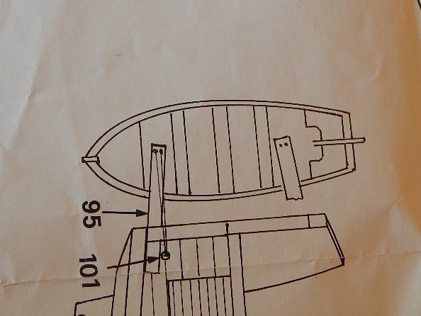
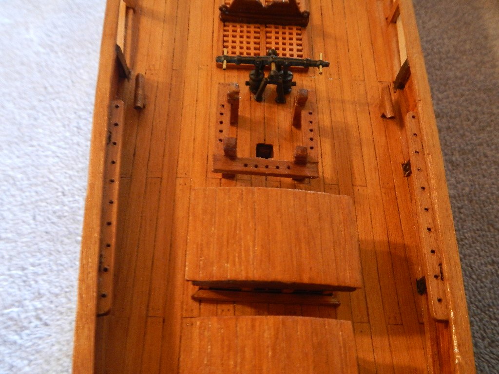
Allen, As it happens, a duplicate copy of the plans were included in the kit that I purchased. I would be willing to send them to you. Send me a private message. Dave
-
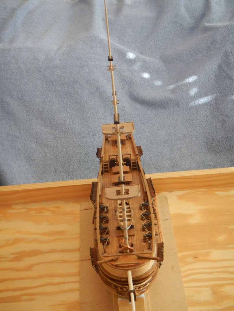
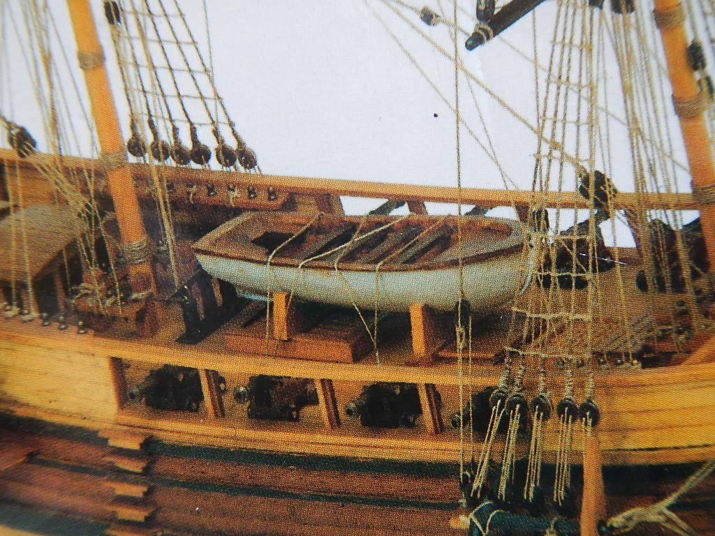
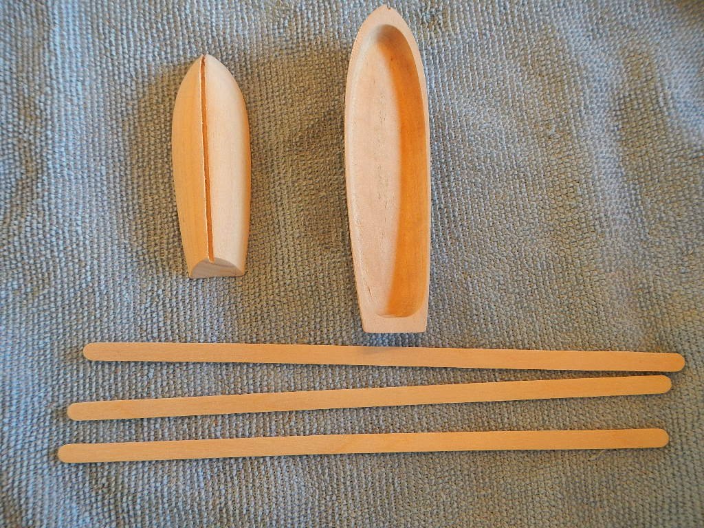
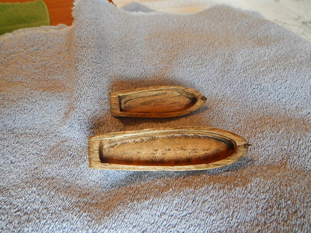
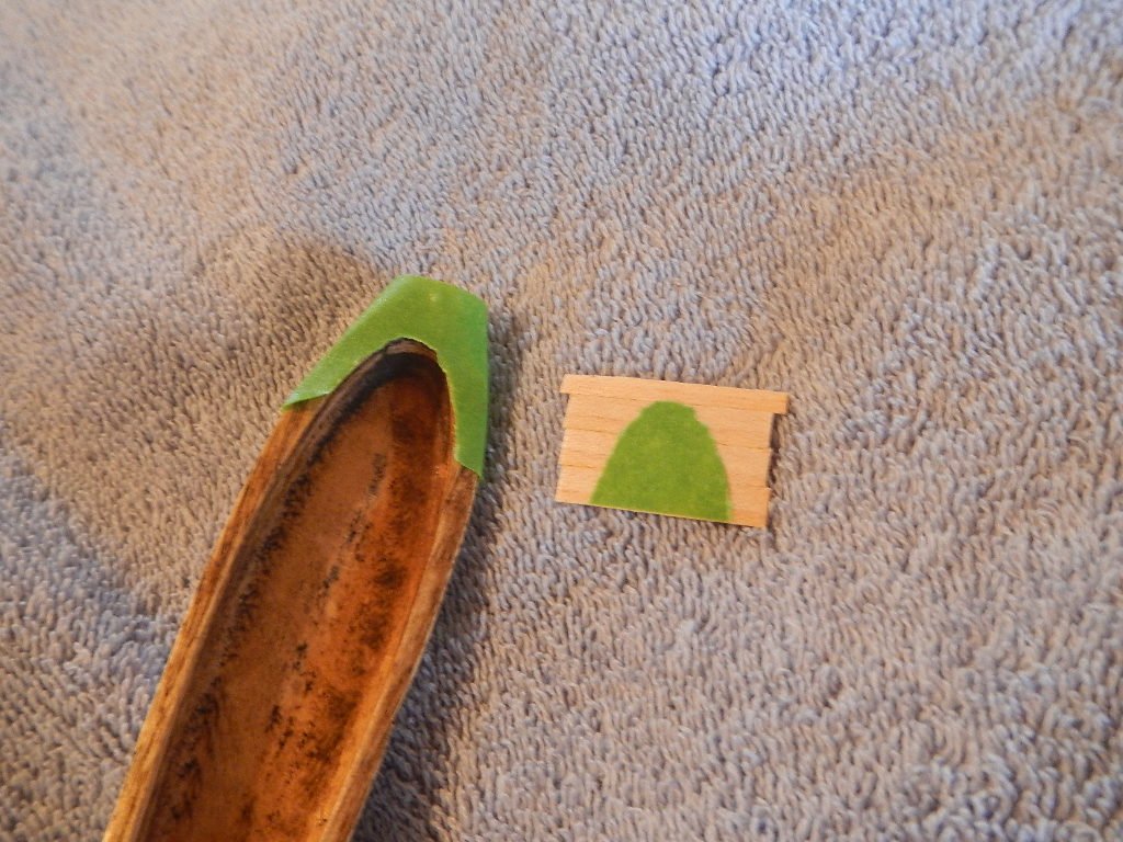
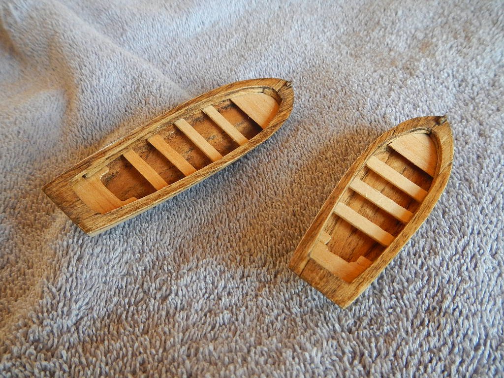
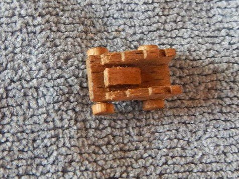
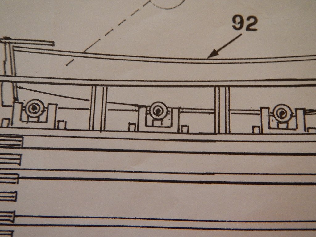
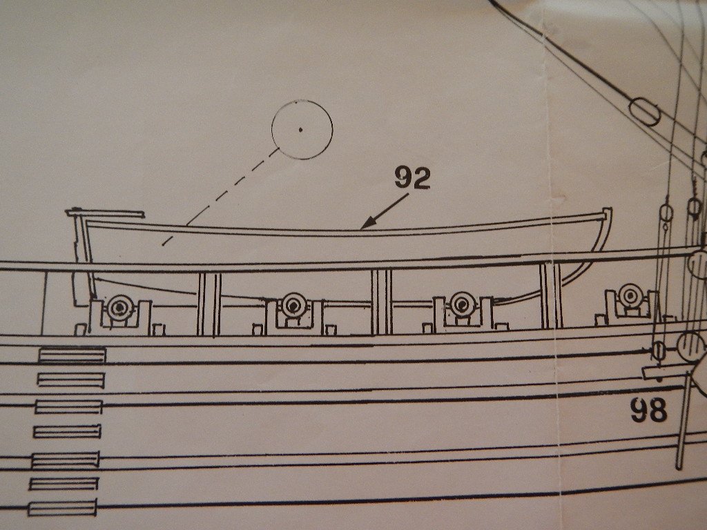
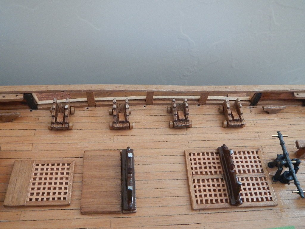
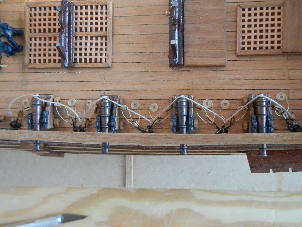
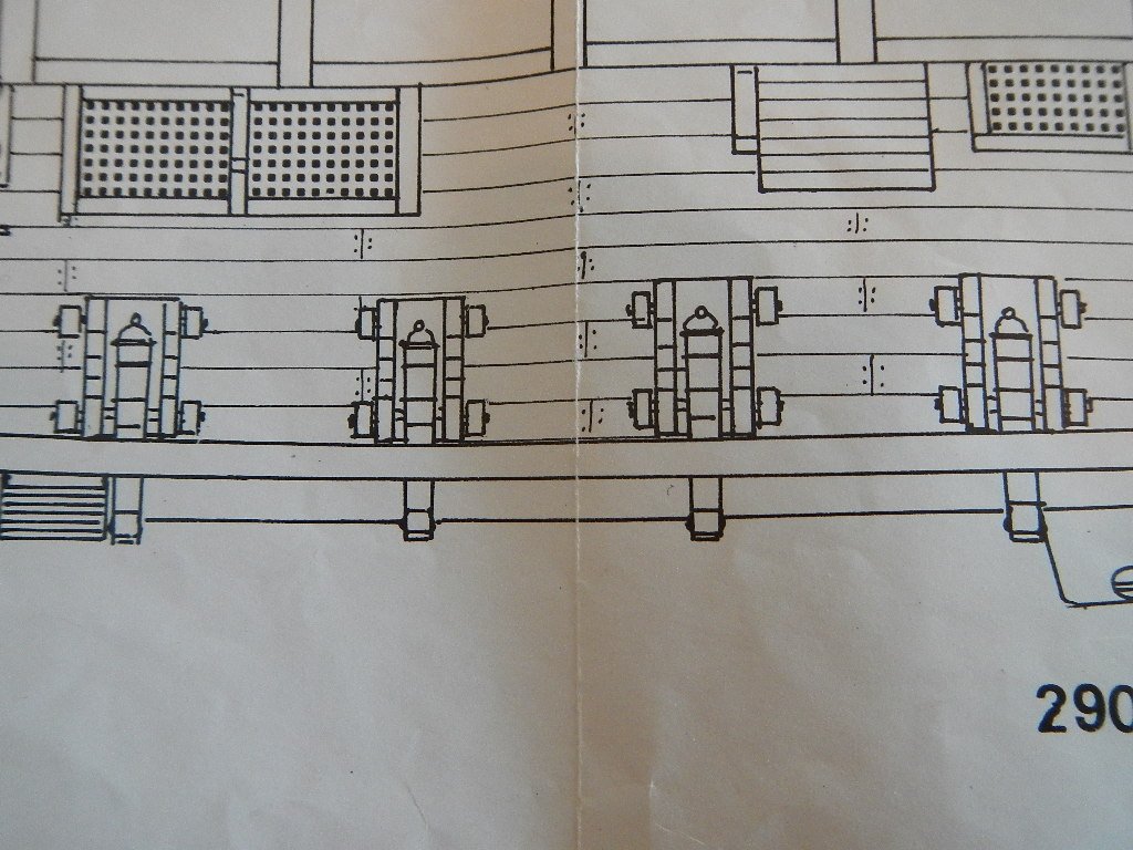
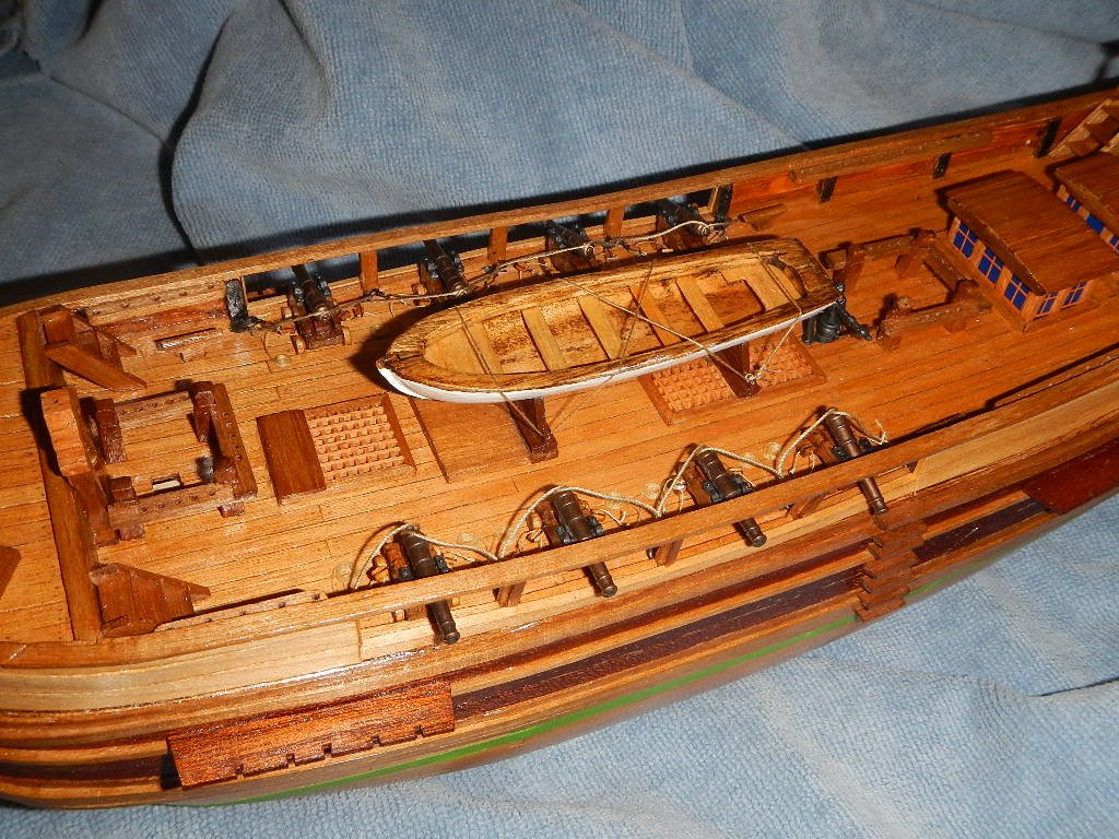
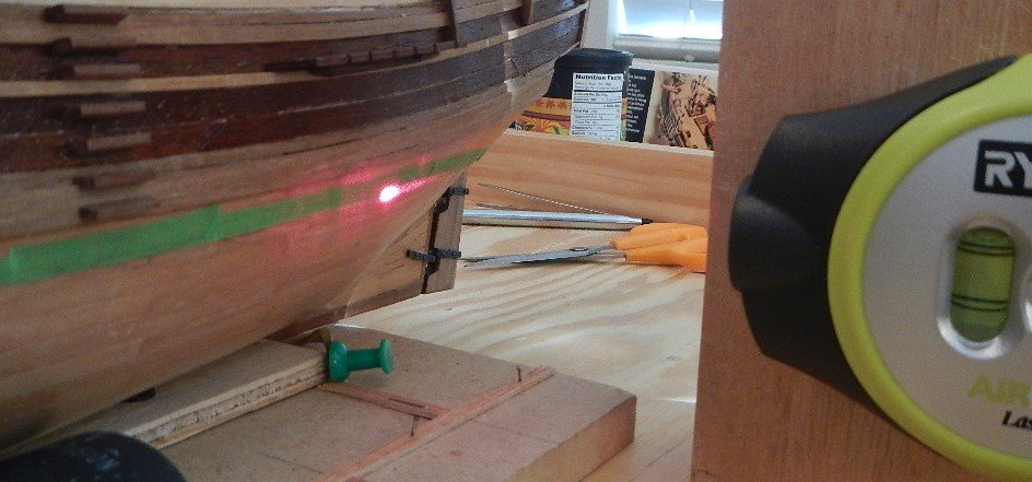
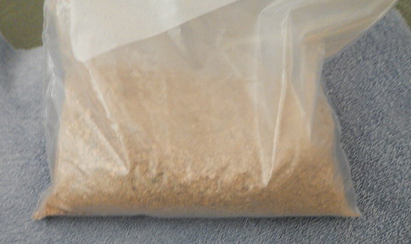
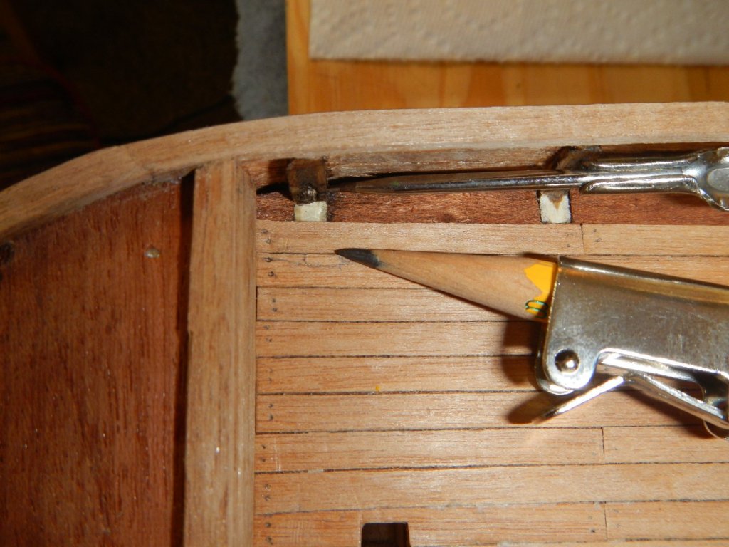
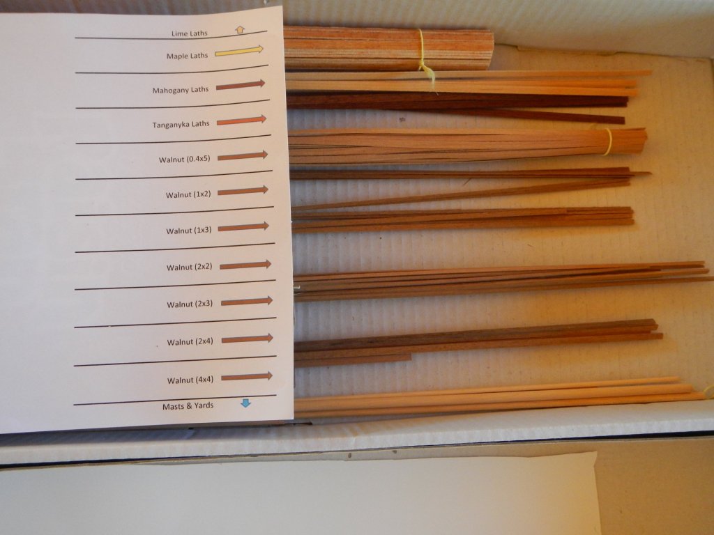
September 18, 2019 Last Touches to the Hull This build log entry covers the remaining items to be attached to the hull / deck. Before I start, however, I wanted to mention two things that were useful during the last build, but I forgot to mention. To hold down things being glued to the deck, I created 3 sandbags, which had sand double bagged in plastic zippered bags. They were very useful in applying pressure to the deck fixtures while the glue was drying. Also, I decided to update the wood inventory to compare what I had left to build with the material on hand. This was important in deciding what piece of wood to use when it was not specified in the model instructions. This proved doubly useful for this segment of the build. This part of the build covers the steps, shroud supports, lifeboats and cannons. In some ways this was one of the most difficult sections, as there was little information on the construction of the lifeboats and cannons, and I felt the sparse mounting of the cannons was inadequate. The wood inventory told me that but I didn’t have enough 2x3mm wood available to use that, so I used 2x4mm wood, which I have plenty since I had purchased an additional meter of it earlier. I think the steps turned out well with that material. When installing the shroud supports, I decided to add a 2x4mm beveled brace (since I knew I had enough) under the shroud supports to provide additional support to them. It seems likely that would be helpful when rigging the shrouds later on. There were no instructions regarding the assembly of the lifeboats, so I had to improvise based on the diagrams and pictures available. Since the wood inventory told me that I did not have enough wood from the kit to provide the keels, railings or inner railings, I decided to acquire some wood that was just about the right width from a well-known, but unnamed coffee shop. With a little sanding, they were the perfect width for those additions to the lifeboat hulls. Since the aft lifeboat was 75% the size of the main lifeboat, I made the keel, inner railings, aft bench and bow bench 25% smaller on the aft lifeboat, but I left the other bench sizes the same on both. I installed the keel, railing and inner railing, then stained the railing and inside of the lifeboats. The benches were made from maple lath and glued to the inner railing. For the bow and aft benches, I made a tape template from the inside of the railing, and I used that for the first cut of the bench, then shaped as needed. After installing the benches, I shellacked the railings and interior and painted the outside of the hull to finish the lifeboats. In the kit, the cannons were shown on the deck with nothing holding them in place and no instructions about their assembly. I thought that looked too simplistic, so I decided to add side tackles and a breech rope to each cannon. I purchased the smallest blocks available from Modeler’s Central and used tan sewing thread for rope. [Kudos to Modeler’s Central – four of the blocks were misdrilled and they sent me replacements free of charge!]. I also added an elevation block to each carriage. It was shown in the diagram, but not mentioned in the instructions. I also drilled a hole on each side of the cannon carriage towards the rear to mount the side tackle block. I positioned the cannon carriages on the deck, which was covered In tape. I marked the position of the wheels, then cut out the tape and sanded the exposed deck so that the glue would adhere. I then glued the carriages to the deck. I stropped the blocks with #34 gauge black annealed wire (a suggestion from MSS). I used an alligator clip to hold the block while attaching the strop. I then attached the breech ropes and side tackles to a set of half ring with a straight end. After building each side (for 4 cannons), I inserted the straight ends into holes drilled into the deck. I then installed the side tackles and breech rope securing the side tackle block to the cannon carriage. That was followed by installation of the cannon with the holding brackets followed by attachment of the breech rope. I completed the cannon installation by winding the appropriate amount to rope to run out the cannon next to each side tackle. There were created by winding them on two-sided tape, then applying shellac to hold them together. I then lifted them off the tape and installed them on the deck overlaying the end of the side tackle rope. [This technique was suggested by barkeater in the Rigging Forum]. After the cannon were installed, I attached the main lifeboat amidships. Finally, I marked the waterline on the hull. After fooling around with a pencil and bracket, I realized I could use a laser level, sitting on my toolbox. As long at the hull and laser level are both level, it makes it very easy to draw an even line across the contours of the hull. Build time to date – 374.5 hrs: 54.75 hrs for the work in this build log entry. Next: Masts and yards MSS - Model Shipbuilding Simplified by Frank Mastini
-
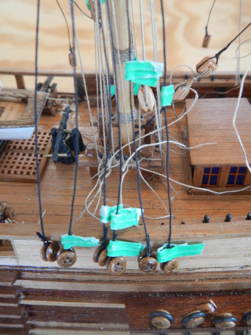
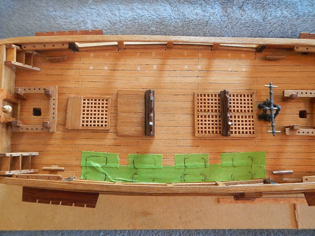
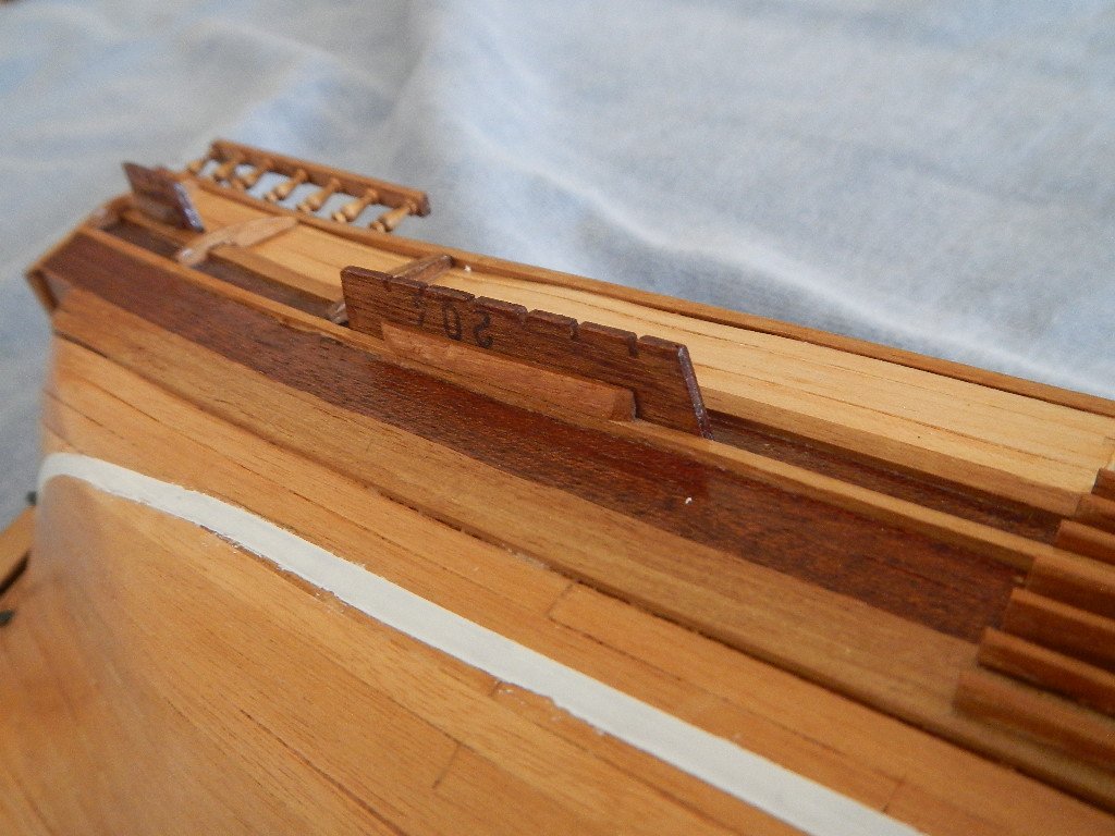
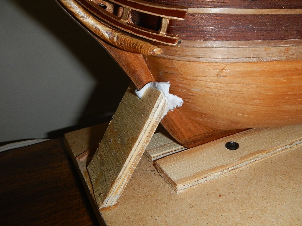
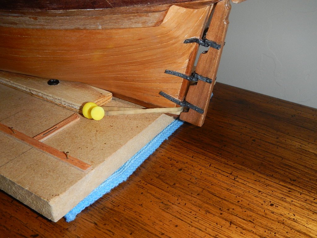
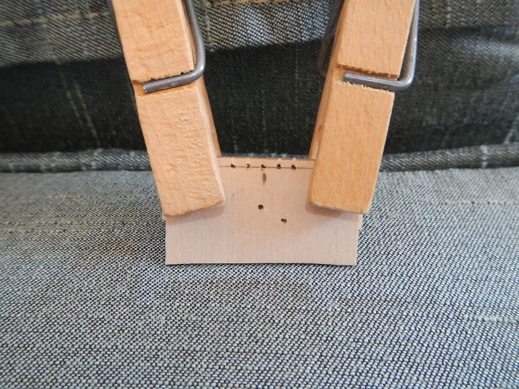
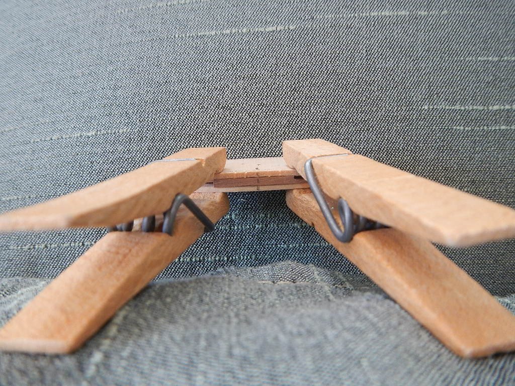
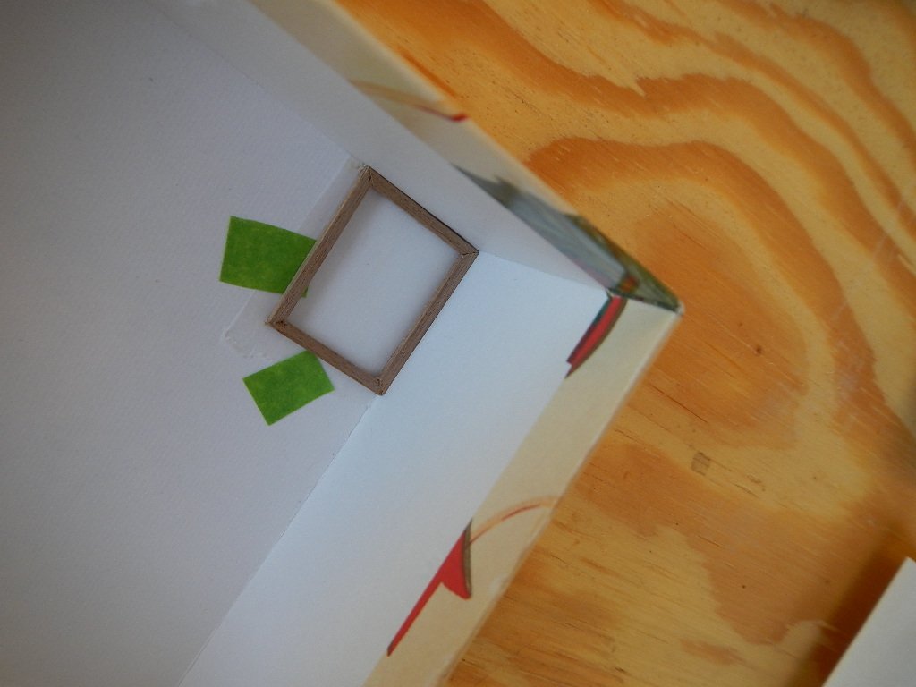
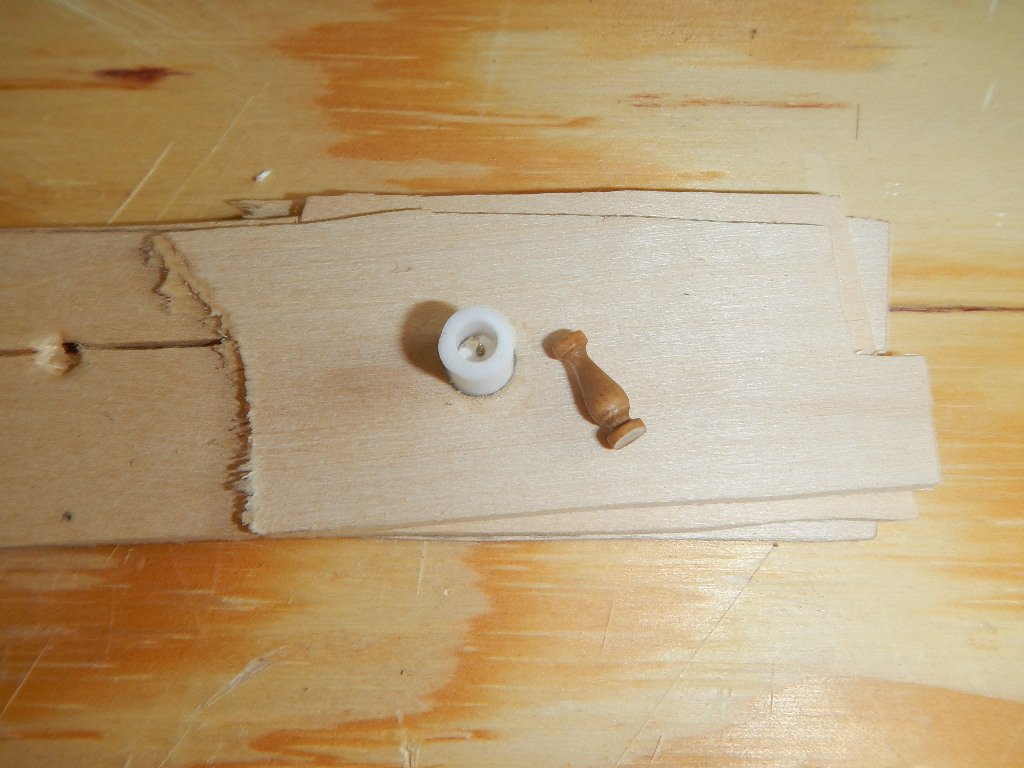
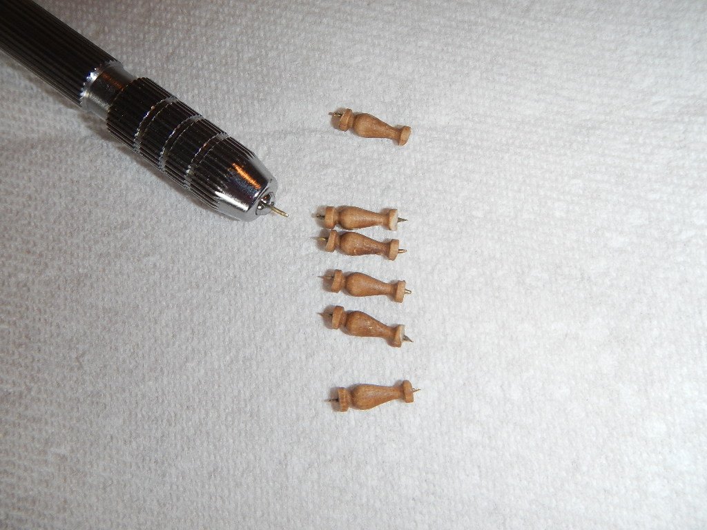
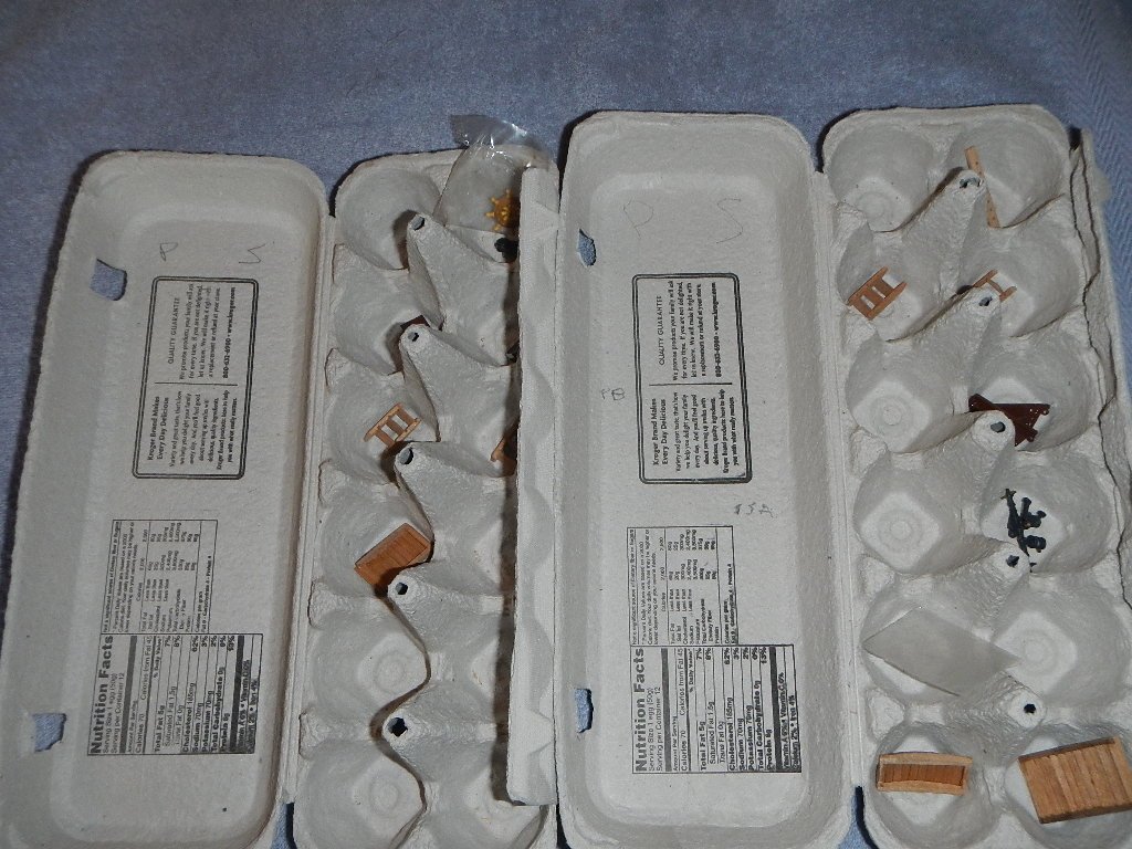
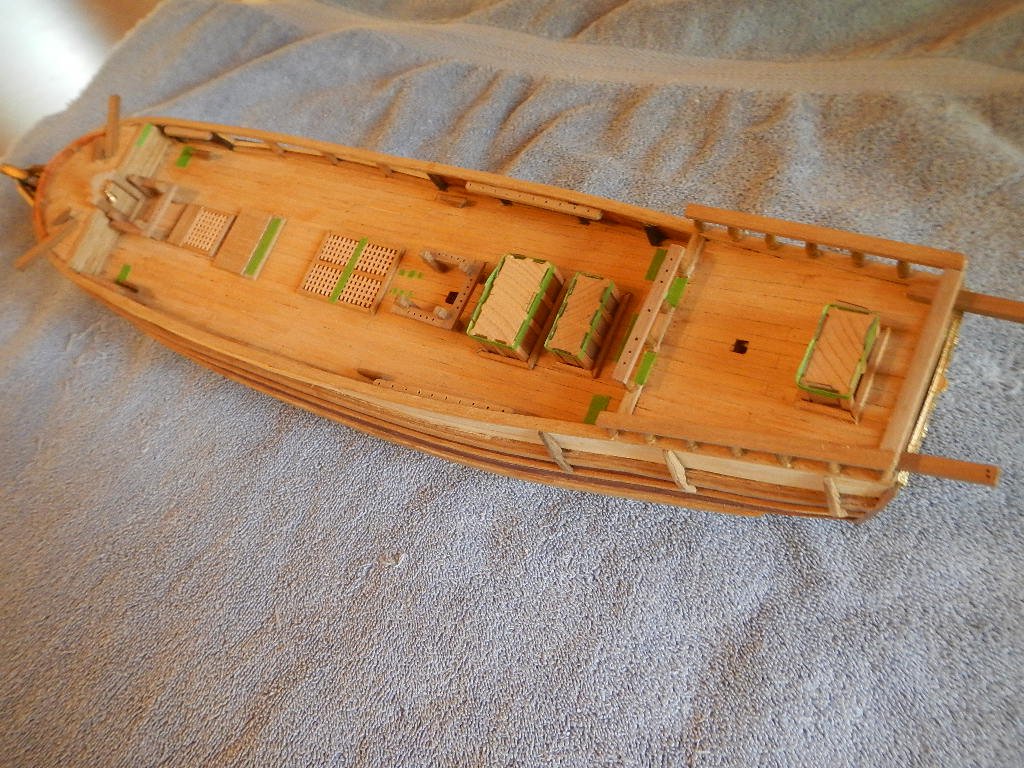
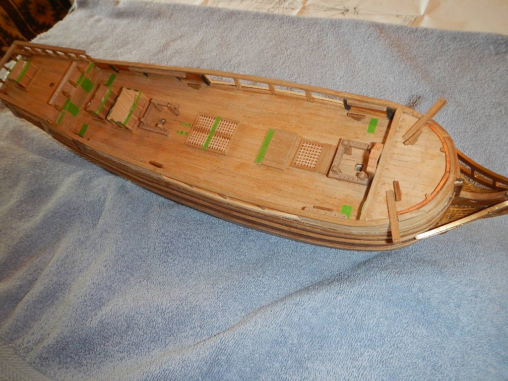
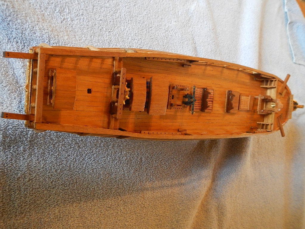
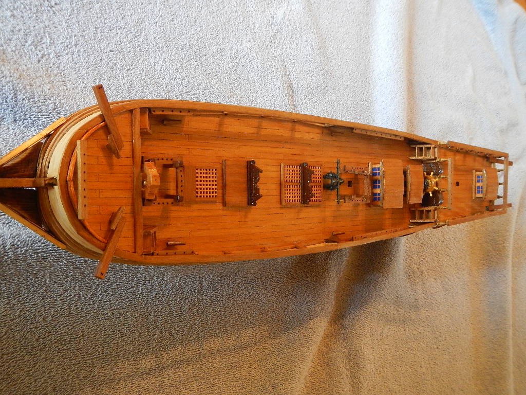
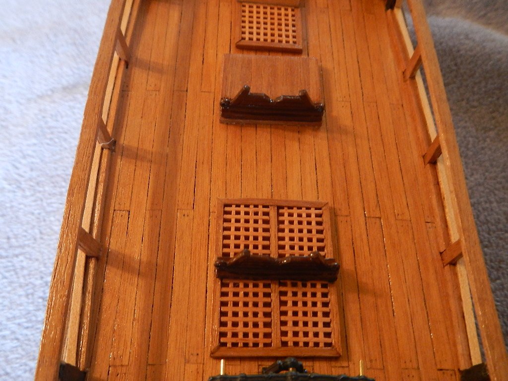
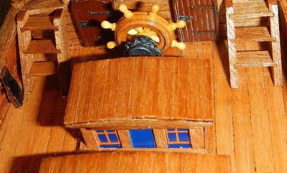
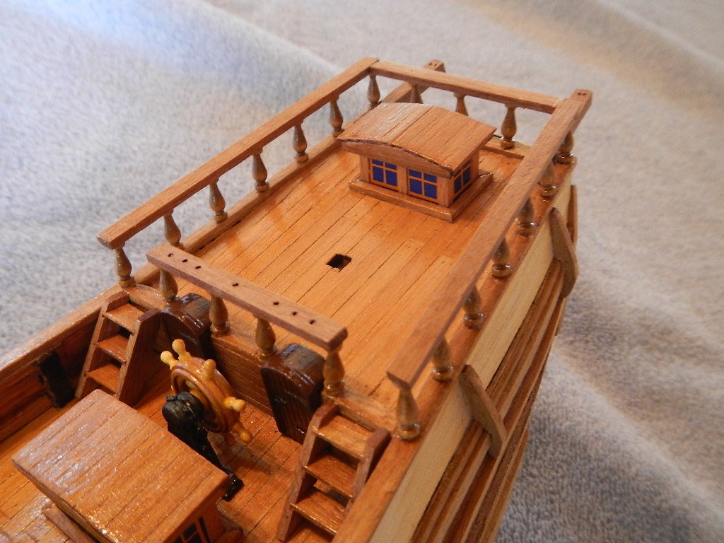
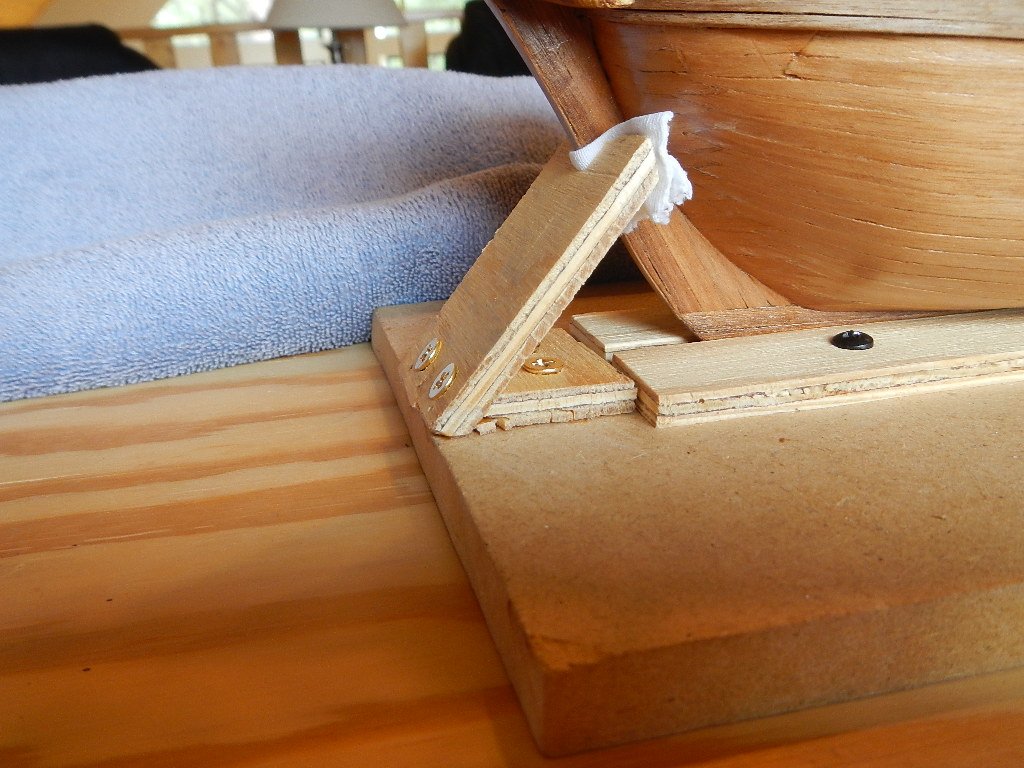
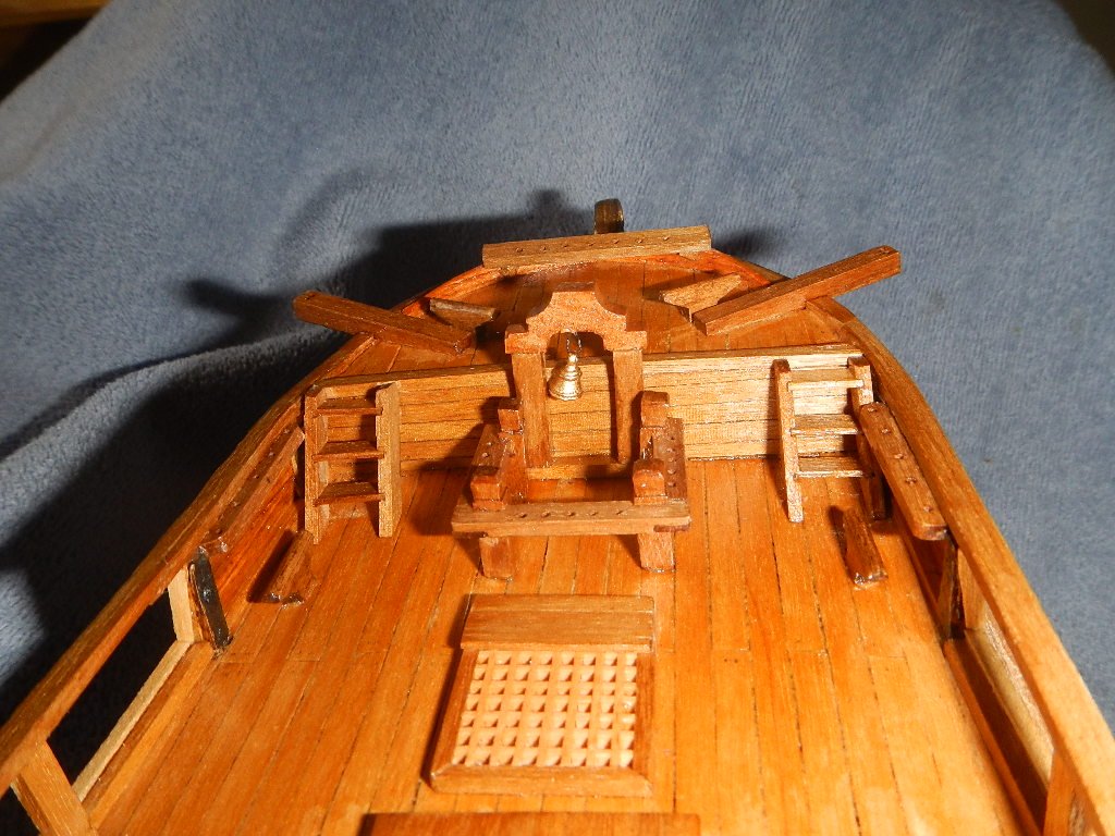
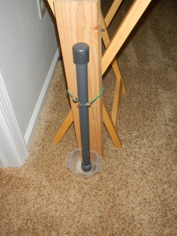
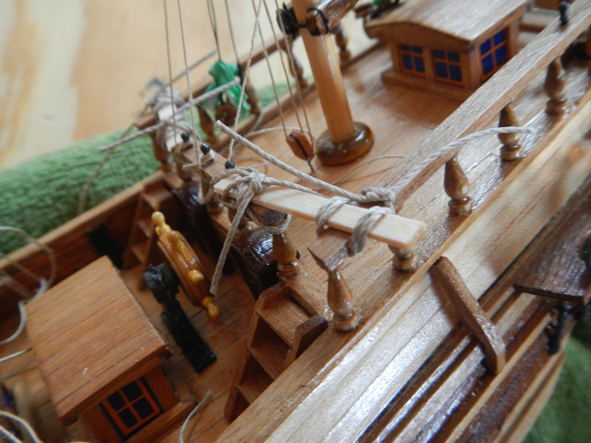
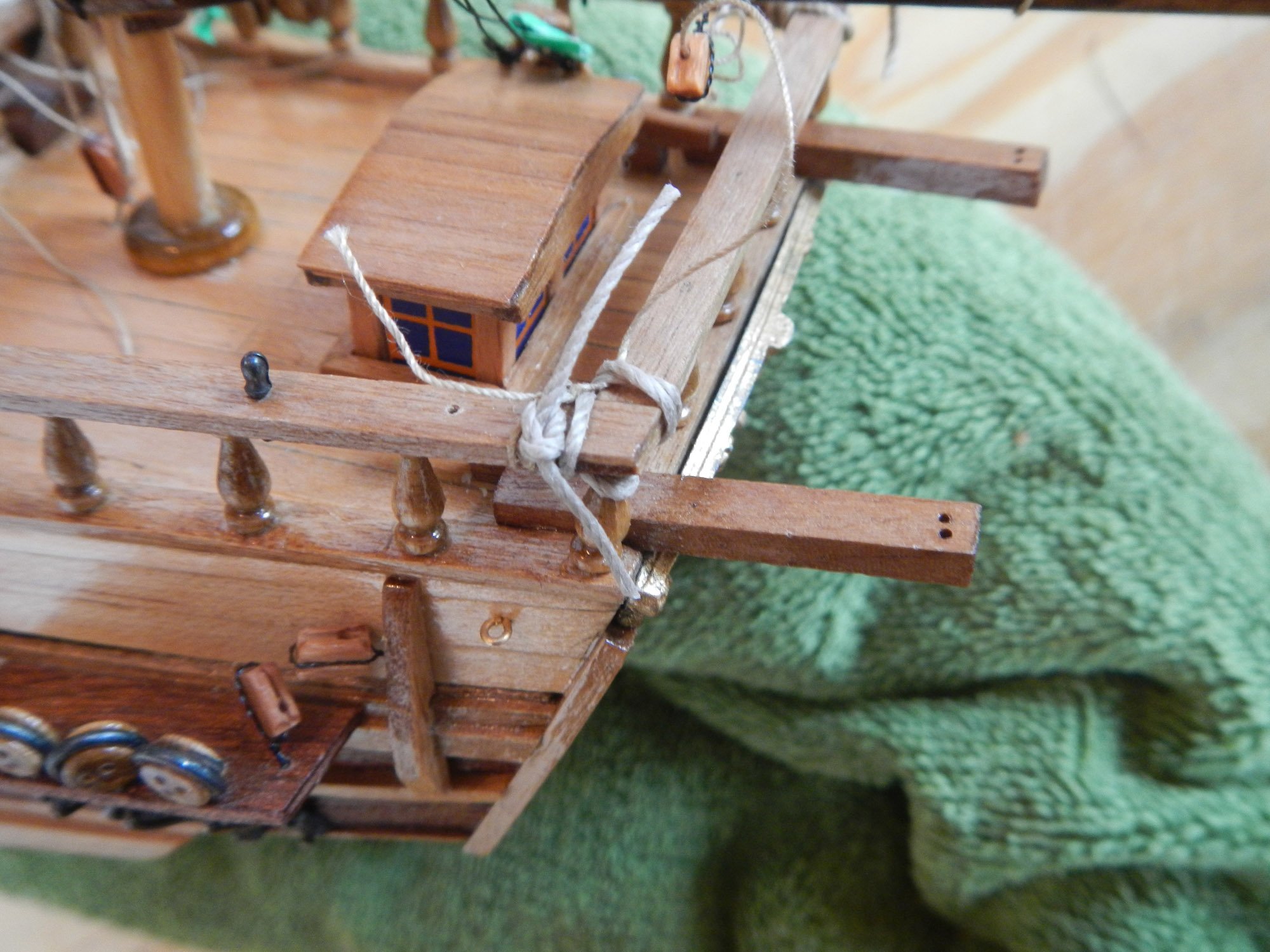
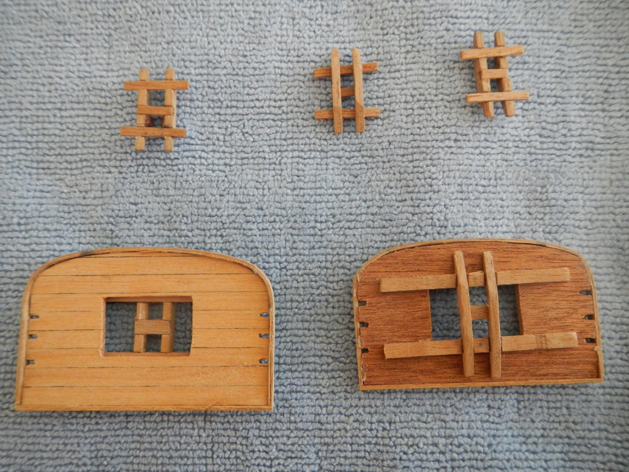
July 12, 2019 Deck Fixtures This build log entry covers the fixtures (or deck furniture as Fernando calls them!) on the decks. Given the conflict between finishing the deck and attaching the fixtures, I decided to build all the fixtures attaching the ones that I could where it would not create a problem when it came time to finish the deck. For example, I attached the anchor davits and cleats to the foredeck, but I did not attach the ladders to the foredeck, as I needed to finish behind them. Since I was doing so much work on the deck, I decided I needed a better holding mechanism for the full. I added an angled brace to the keel in the front and a rubber band in the back to push it against the brace. The first brace did not hold up, so this is version 2. There are a lot of pieces for this part of the project, so I used egg cartons to store the completed pieces until I was ready to install them. This way I could keep them in order and tell starboard fixtures from port fixtures. For all the posts in the fixtures, I added pins to help hold them in place (another recommendation by MSS). This includes the binnacle, the belay pin racks around the masts, and the balusters for the railing around the quarterdeck. To drill out the belay pin racks, I created a die from balsa wood so that the holes would be properly positioned and evenly spaced. I used this technique for all the belay pin racks. To try to make sure that the hatches and skylight moldings were square, I glued them together inside the square corner of a box. I put wax paper underneath so that the fixture would not get stuck to the box. In order to be able to drill the balusters for the quarterdeck railing, I created another die that would mark the center of the baluster so that I could drill it (there was not a lot of room for error on the baluster!). Here is a completed set of balusters for one side of the railing. I marked the top and bottom of the railing while side by side to ensure uniformity in baluster placement. I used the end of a brad in the hand drill to make the corresponding holes in the railing and deck for the pins. This same technique was used on the other fixtures with pins. Here are the decks with everything installed before the finish was applied. The green tape masks off areas for gluing on fixtures that will be added after the finish. … And here are the decks after finishing of the deck and the remaining fixtures, then installing everything. · Anchor davits, cleats and bowsprit belay pin rack on the foredeck · Binnacle with bell, ladders, foremast belay pin rack, forward belay pin racks and cleats and the forward hatch on the main deck · Second and third hatches and lifeboat cradles · Pump, mainmast belay pin rack, middeck belay pin racks and cleats and forward skylight · Middle skylight, ladders to the quarterdeck, helm and hatches to quarterdeck on the main deck · Quarterdeck railing (including belay pin rack), aft skylight and davits for aft lifeboat on quarterdeck Note: The kit provided windows for the three skylights, but was short two windows for the second skylight. I made up the remaining two windows using extra window in the middle window fore and aft, as they are the hardest to see (normally!). Build time to date – 319.75 hrs: 61 hrs for the work in this build log entry. MSS - Model Shipbuilding Simplified by Frank Mastini
-
Hi, Fernando! Yes, the deck fixtures are next. There are a lot of pieces, but it seems pretty straight forward (famous last words!). Looking forward to getting started. PS I like your emoticon! Dave
-
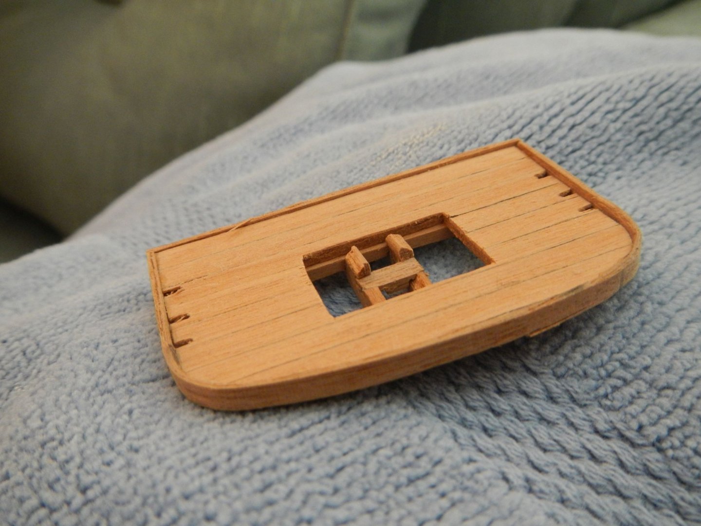
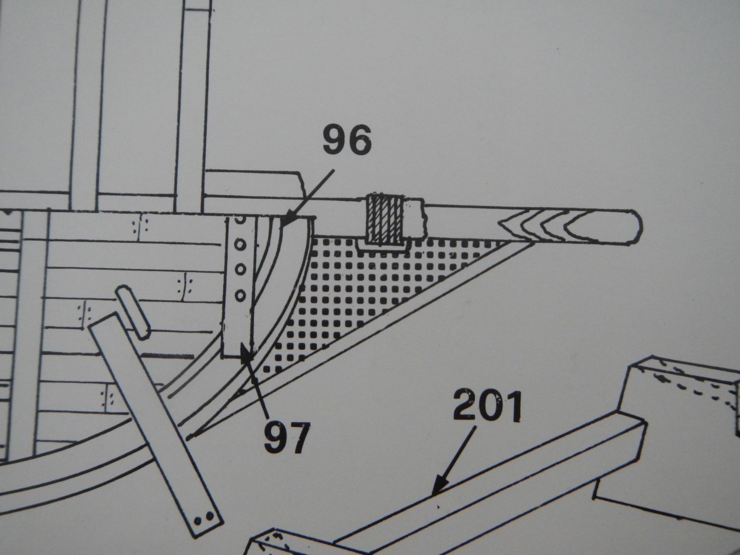
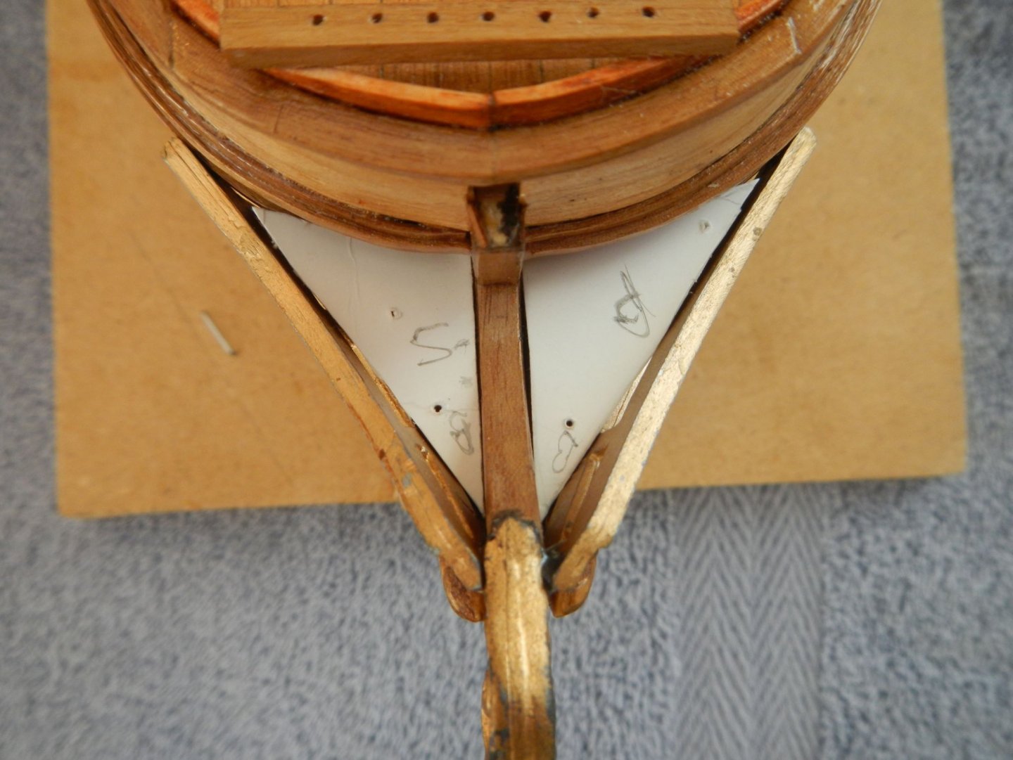
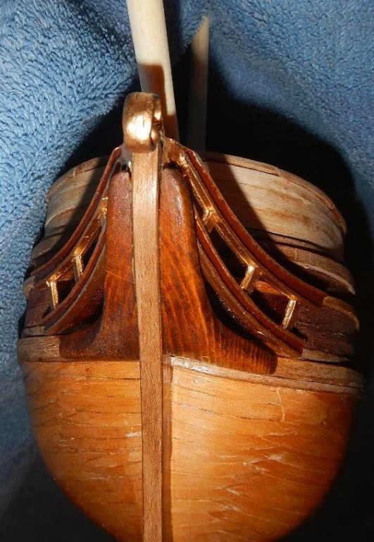
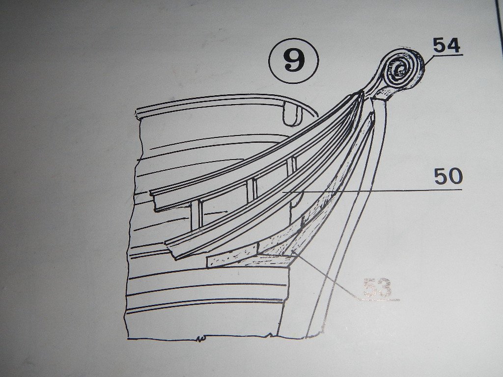
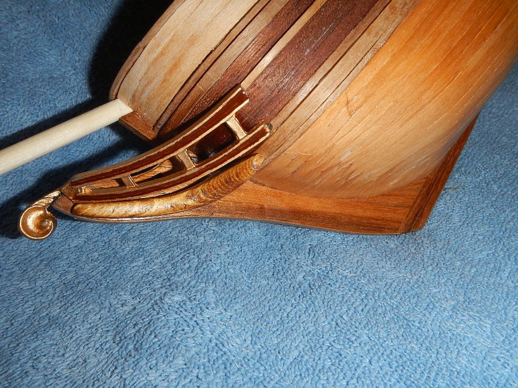
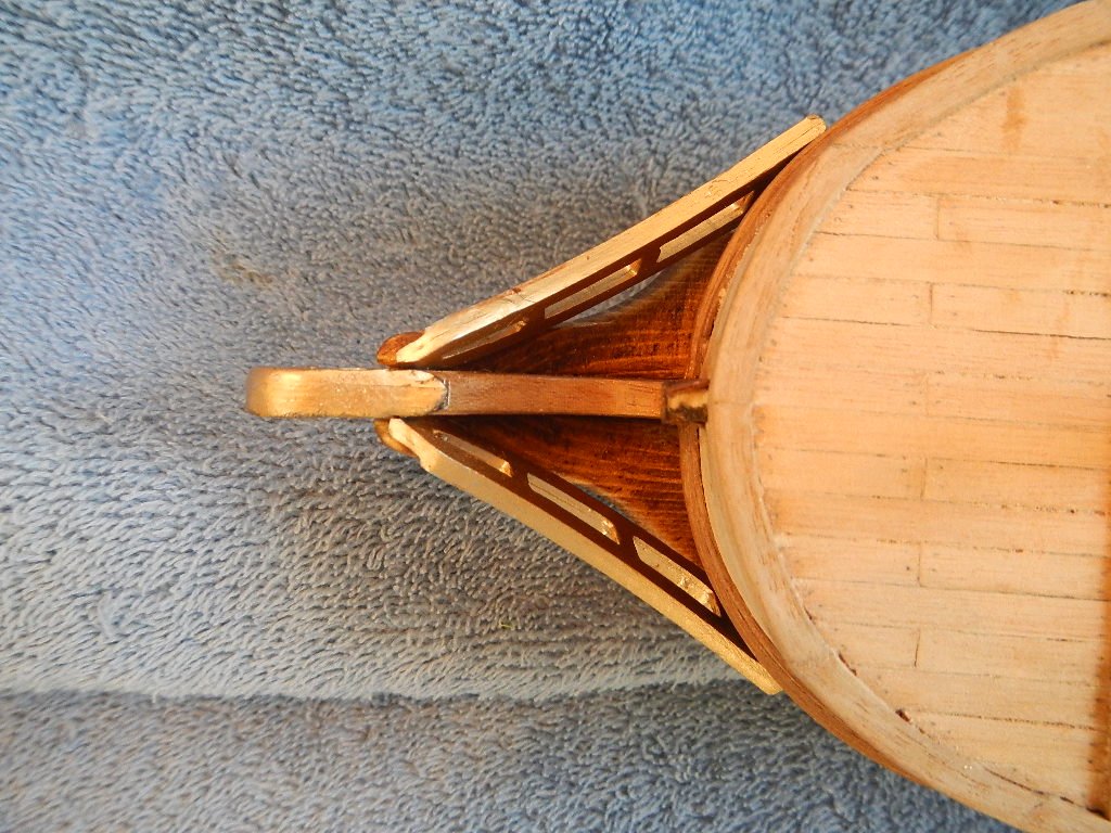
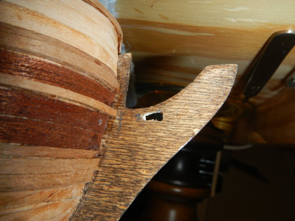
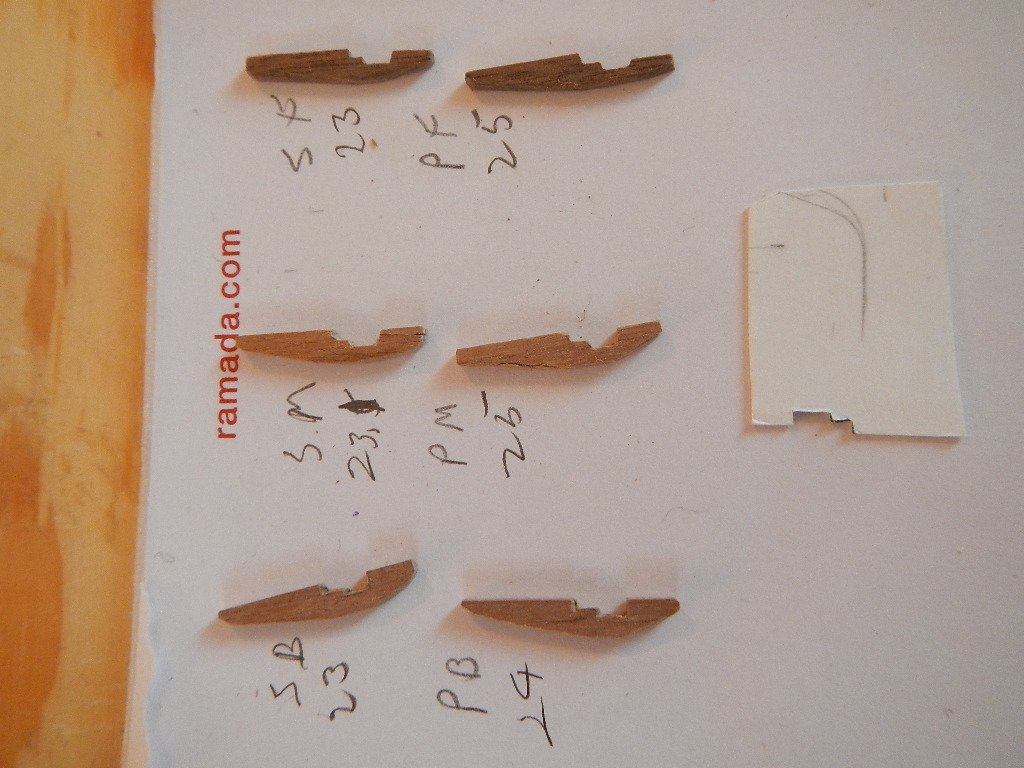
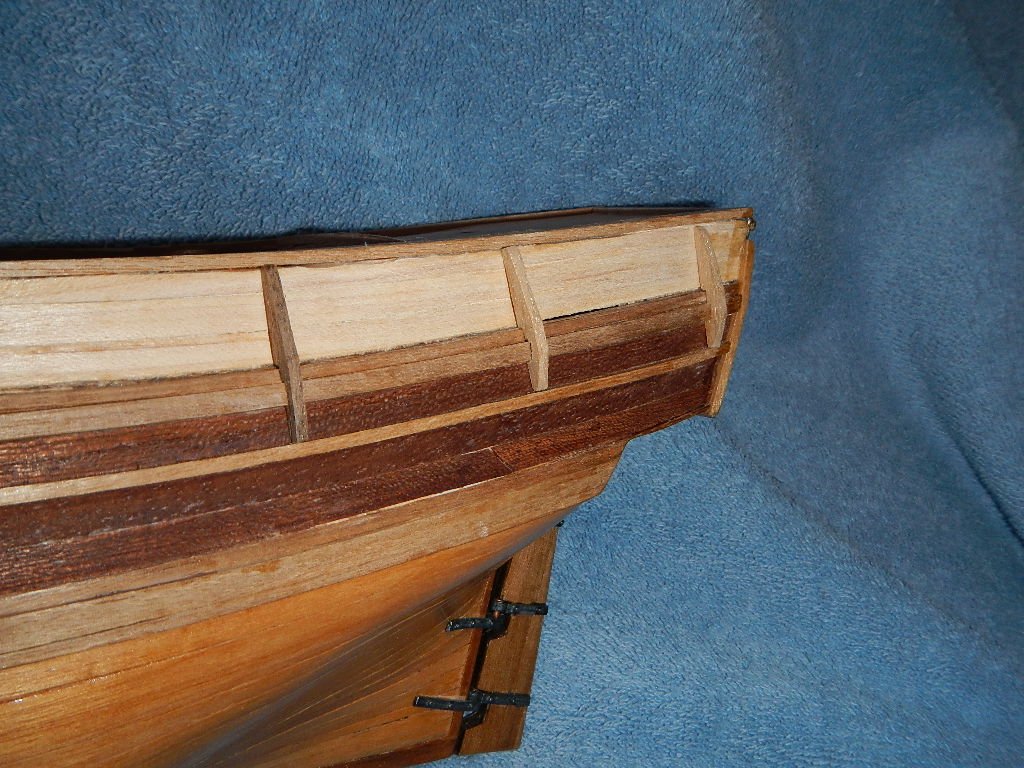
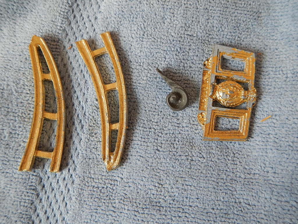
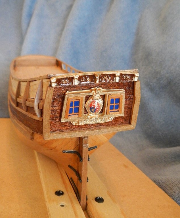
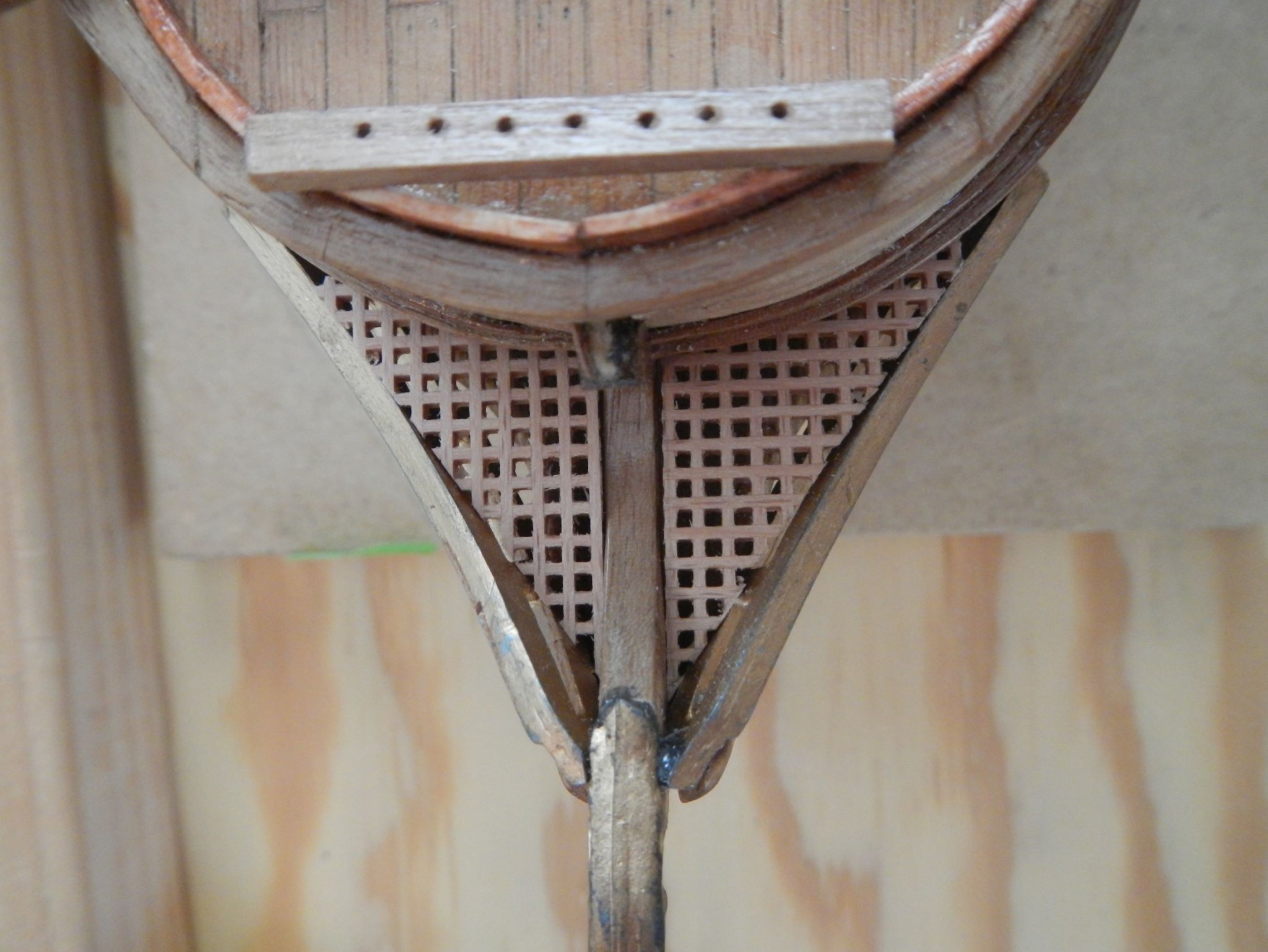
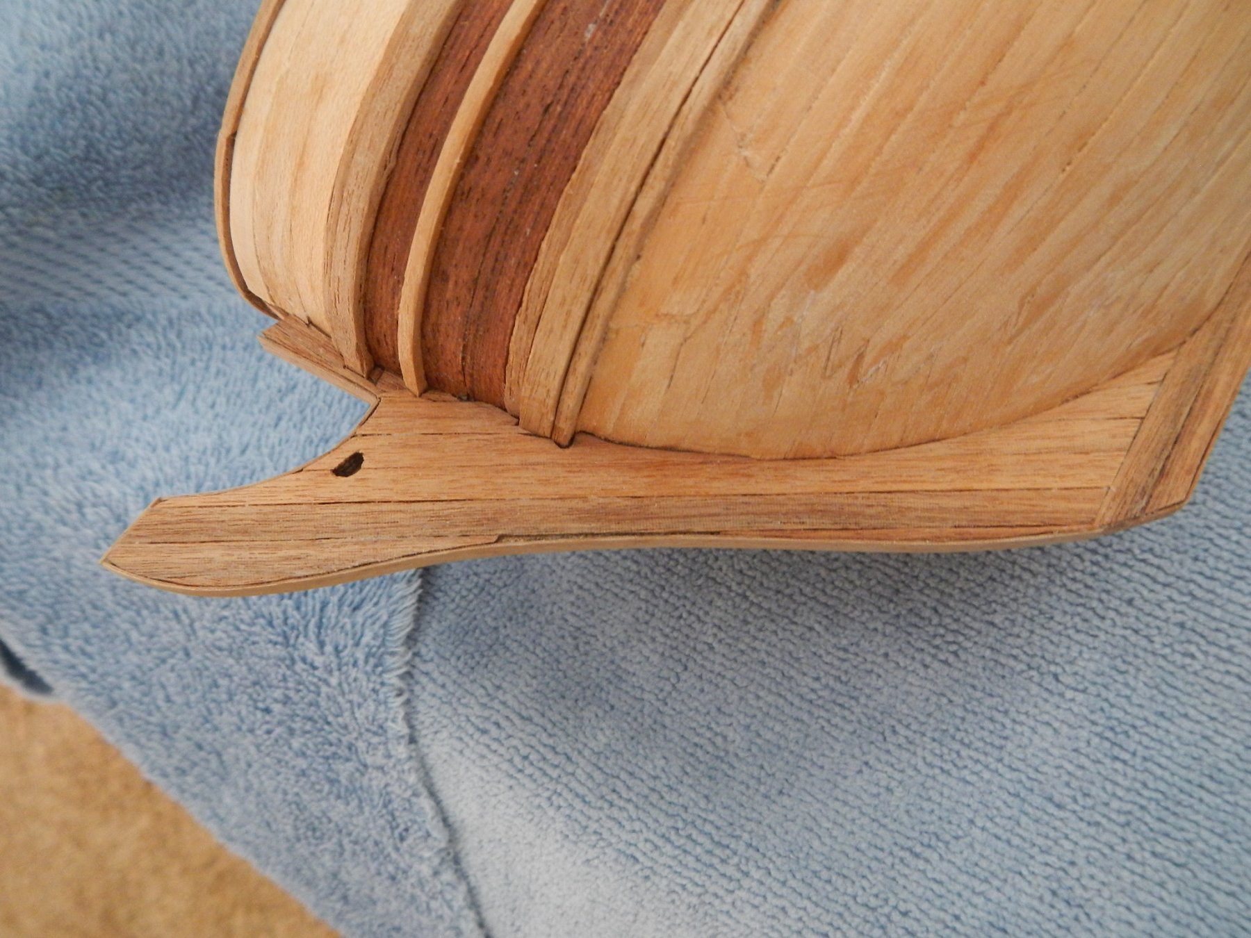
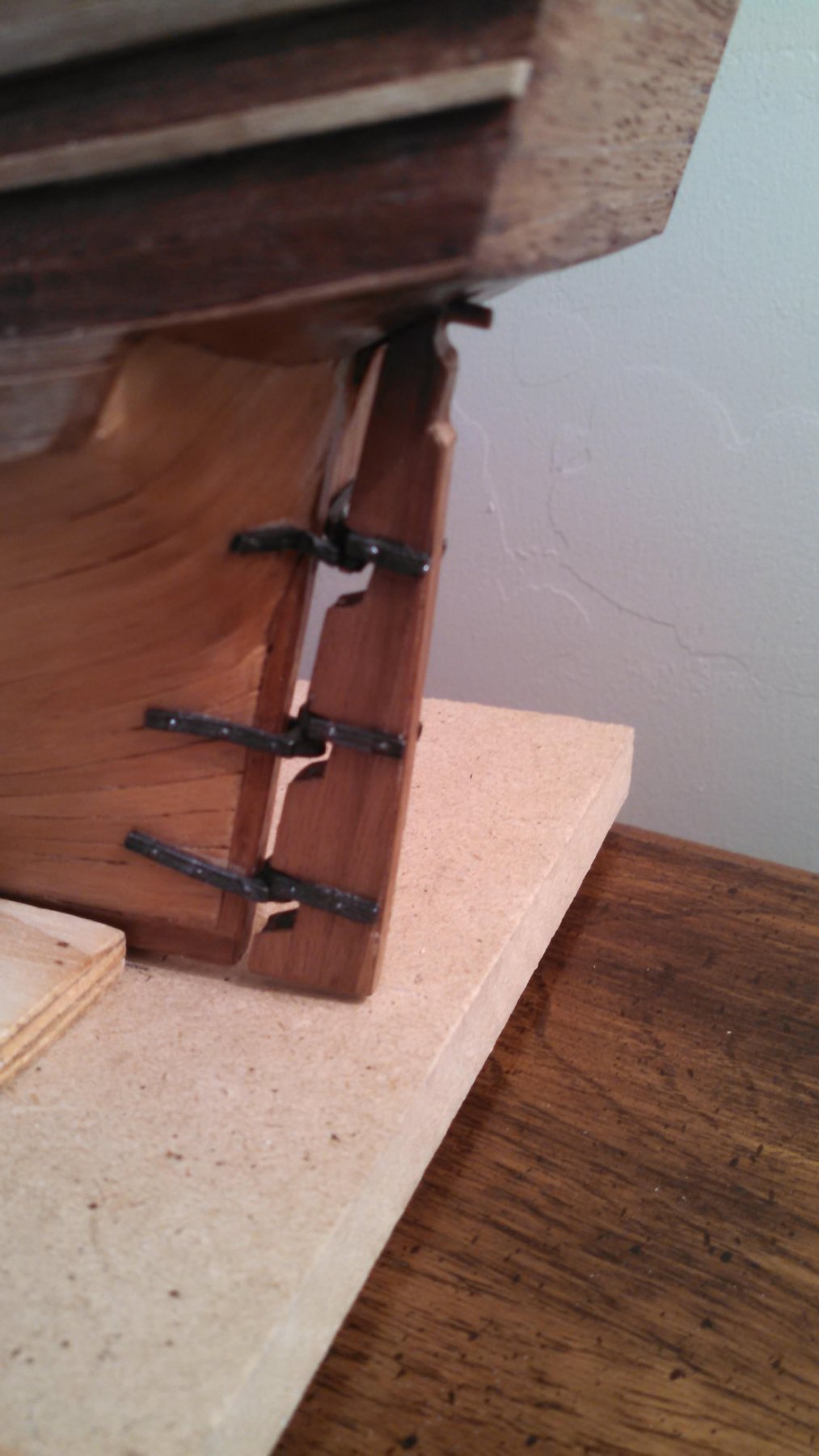
February 18, 2019 Complete hull, decking and hull attachments First, I want to give credit to MSS for the deck plank cutting jig. I should have mentioned that in the previous blog. Also, the use of a compass for drawing cut lines on the edge deck planking (mentioned below) was suggested by the article, A primer on planking by David Antscherl, that I found in the database of articles on Framing and Planking. I continued with completing the main and fore deck. I used a compass set to 1 or 2 board widths to provide an initial cutting guide for the edge planks. This made fitting the planks go a lot faster and cleaner. Here is the ship with all decks planked. A closer look at the plank fitting on the main deck. I then went back to build in gunwales on the open portion of the main deck (as mentioned in the previous blog). I added a 2 mm wide length of underplanking on each side, then covered it with Maple lath on the front and top. I also add Maple lath to each end of the opening. I think the result turned out rather well. The next step is planking the keel. Before starting that I drilled out a hole for the Bowsprit woolds. The hole is a little ragged, but I’ll clean that up when I cover it with planking. I planked the entire keel bow to stern, including the edge of the keel. Note the hole for the bowsprit woolds. In order for the planks on the keel bow to be at a consistent angle, I set up this cutting jig. However, I don’t think planking the edge was planned for in the kit, because I ran out of the walnut planking. I’m guessing that it wasn’t to be planked as it is for the most part painted (similar to the inside of the bulwark). However, I have decided to leave the hull unpainted to better see the beautiful woods used to make it. I ended up ordering additional planking from Modelers Central in Australia. While ordering, I got a 2mm x 4mm walnut plank to replace the one I had to use on the port side sheerstrakes (along with a 2mm x 2mm plank) when I was short of the two 2mm x 3mm walnut needed. I also picked up a couple of blocks missing in the kit and some blocks for anchoring the cannon on the deck. The company was easy to work with and delivered as promised. After completing the keel planking, I planked the rudder. The rudder came without the cutouts for the hinges, so I had to do that before planking. To create the dowel for the tiller, I rounded off the edges of a 2mm x 2mm piece of walnut. After all planking was done, I applied diluted wood glue to the edges, wiped off the excess, and sanded (another MSS technique). This is the same thing I had done on the hull and the decks. It does an amazing job of smoothing out the planking. I attached the rudder to the hull with the three sets of hinges then finished the lower part of the keel, rudder and lower part of the hull. Since I saw many recommendations of using diluted shellac for a “primer” coat, I decided to use shellac for the finish. I did the primer coat, the two additional coats of shellac full strength. I like the look and feel of the finished product. Next was putting the fenders on the aft section of the ship. This is where I found out that 25 year old walnut (yes, the kit was 25 years old when I got it!) was pretty brittle. Out of the six pieces I originally cut, only three survived carving out the hull profile. The other three I made from the recently purchased 2mm x 4mm walnut. It was much easier with the new wood. I used my notepad with the various lengths to keep track of the fenders. The poster board template I used to make the initial cuts is also shown. The metal pieces were the next things I worked on. As you can see, after banging around in the box for 25 years, they were pretty beat up. I used steel wool on them, then re-sprayed them. The taff rail was the only piece that survived pretty much intact. I did the following detail painting on the metal pieces: · Bow Serpents – I painted in the grooves with brown. · Taffrail - I painted the background brown to bring out the carvings. · Transom molding – After some research, I realized that it was the Royal coat of arms of the United Kingdom. I tried as best I could to replicate that. Given the size, I thought it turned out rather well. The instructions had minimal painting instructions regarding the transom molding and none for the other pieces. However, the pictures on the box had shown the painting indicated for the other two items. All metal items, including the rudder hinges, were attached using epoxy glue. The installation of the bow decoration, bow serpents and bow serpent bottoms were shown in Diagram 9 of the instructions, but no instructions were given regarding their installation. In addition, the bow serpent bottoms, which are indicated in the parts list to be metal, were missing from the kit. I decided to carve them from some existing fir that I had available. Here is how they looked after rough carving. In the end, I thought they turned out pretty well. I filed down the attachment points on the bow serpents to more closely match the hull / keel surface and provide contact area for the epoxy glue. TIP: The metal in this kit is very brittle and does not bend! Believe me, I found this out the hard way! The last item to be installed was the transom molding. I thought that the windows provided in the kit looked unfinished in the molding (plus the lines framing the windows did not match the actual opening too well). I decided to frames the windows with small pieces of Tanganyika wood (used for the decks and hull). Lastly, I decided to put a little more color to the inside of the bulwarks, so I stained the bulwark with a maple stain and painted the stanchions black. Build time to date – 258.75 hrs: 57.5 hrs for the work in this build log entry. MSS - Model Shipbuilding Simplified by Frank Mastini


-
Best finish for wood ships
Dave3092 replied to Dave3092's topic in Painting, finishing and weathering products and techniques
Thanks to everyone for their comments. This gives me options to consider. -
I am at the point in my build of the HMS Beagle that I need to start thinking about finishing the wooden planked hull. I am looking for suggestions on the best products, finish and application technique to do this so the wood is shown to best effect, yet it is easy to maintain after completion (i.e. doesn't attract dust, etc.). Product - Tung oil, shellac, spar varnish or other Finish - matte, satin, semi-gloss or high gloss Application - brush, spray, cloth or other Also, I understand that is hard to glue the detail work to the deck or hull after it has been finished, but it would also seem to be hard to finish the deck or hull with all the detail work on it. Comments? Thanks!
-
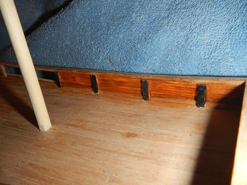
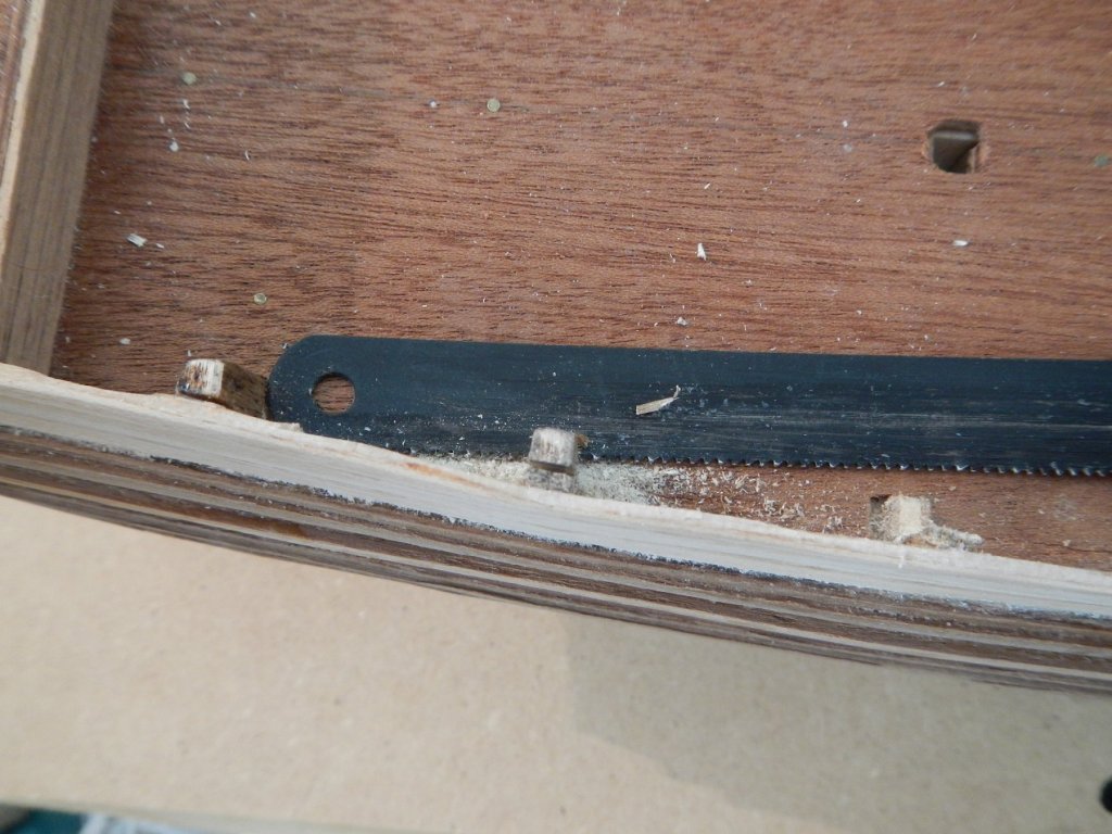
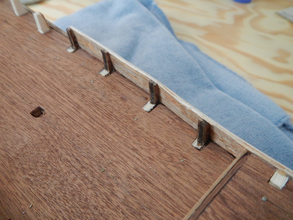
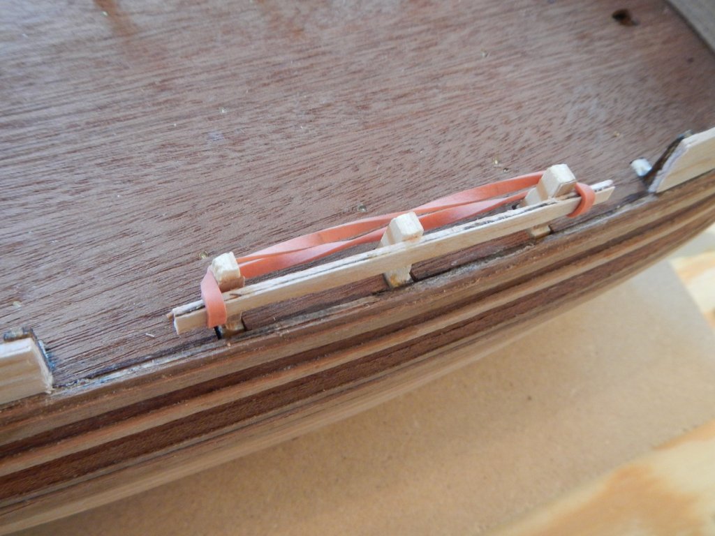
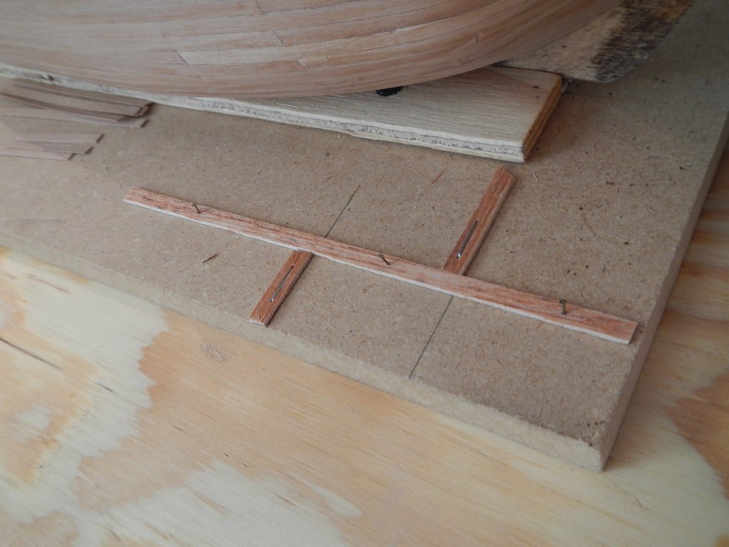
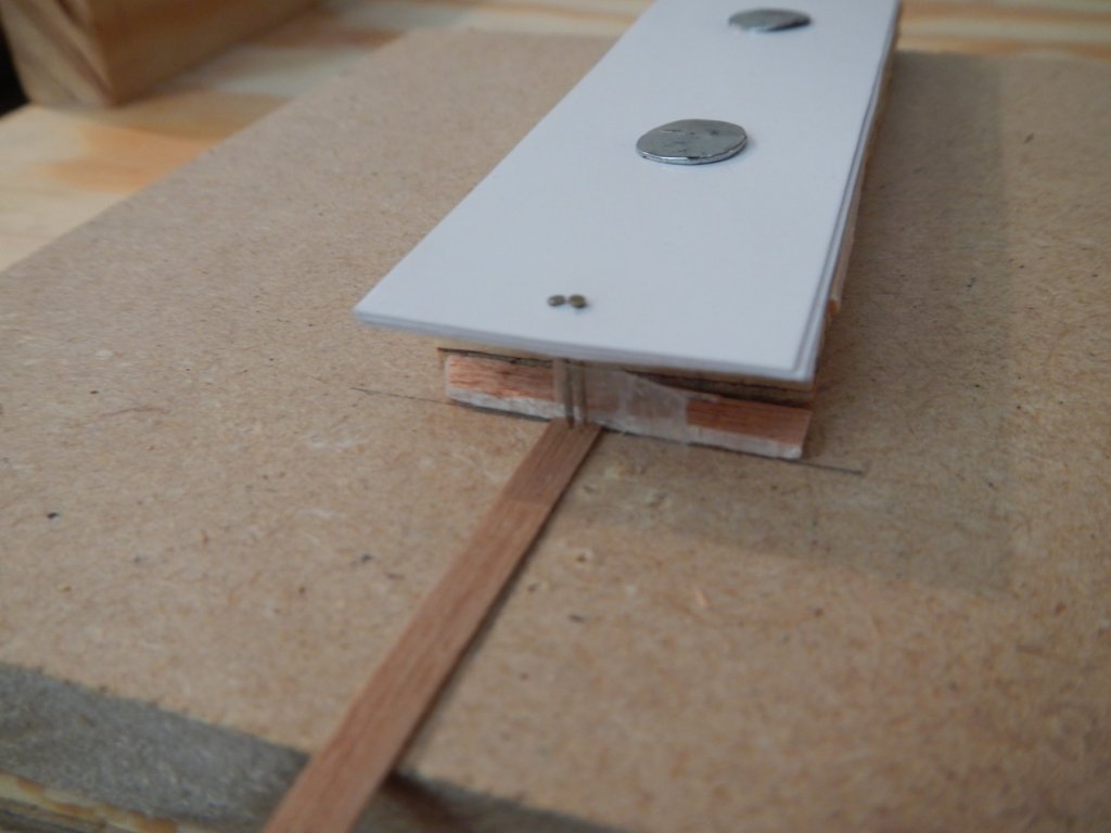
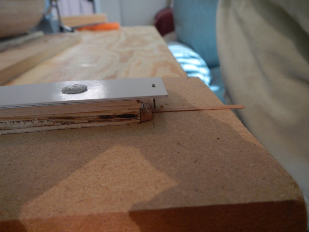
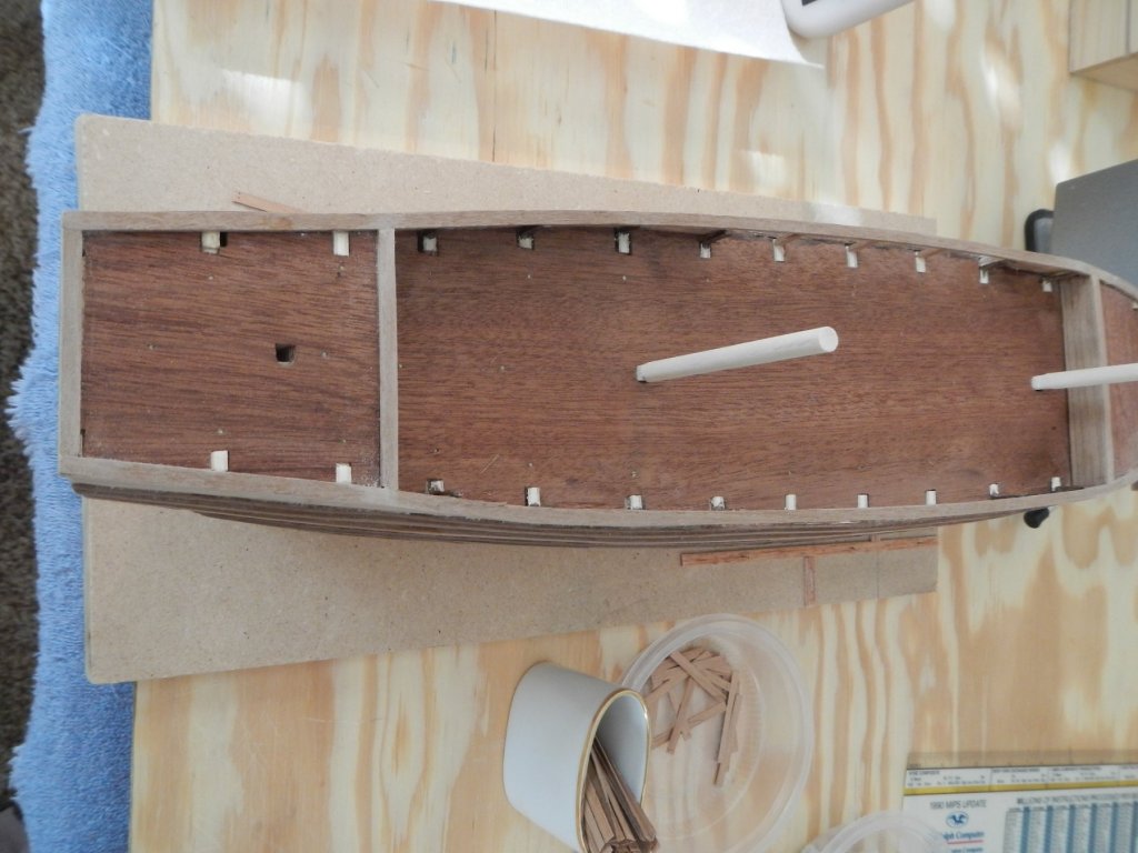
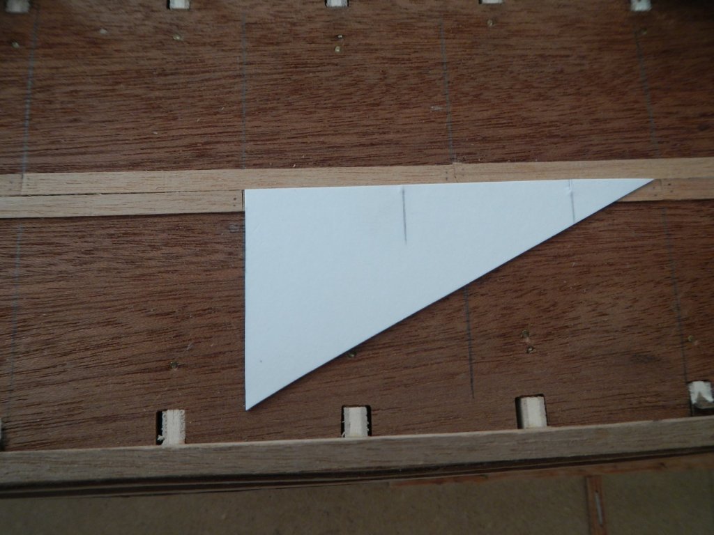
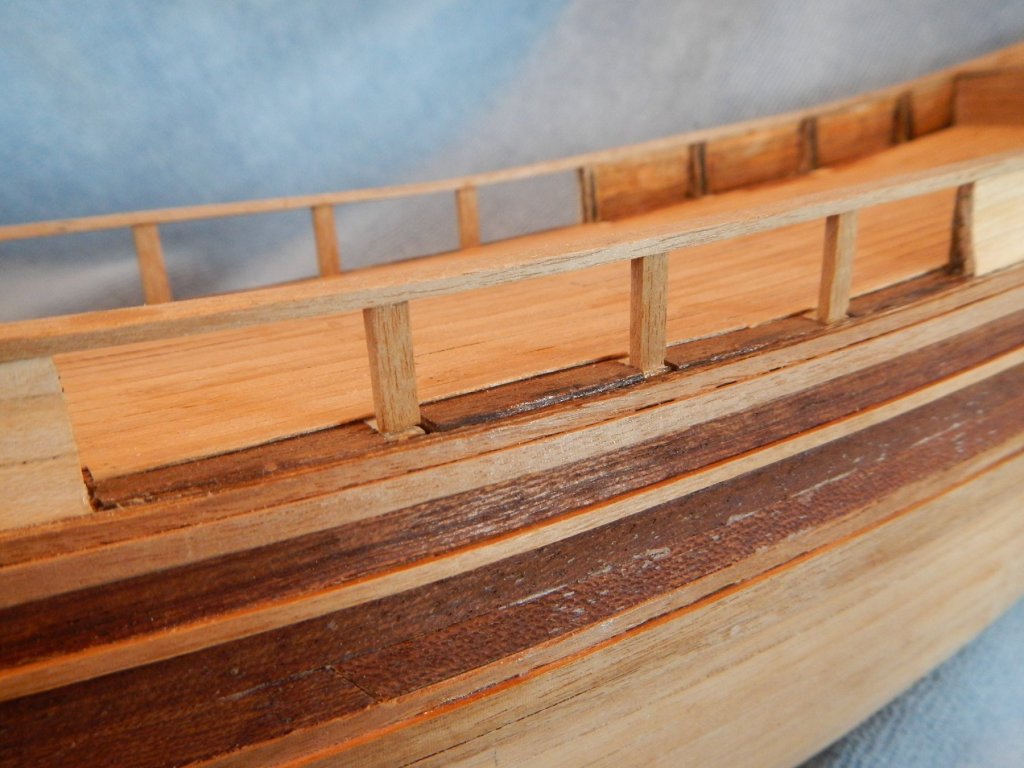
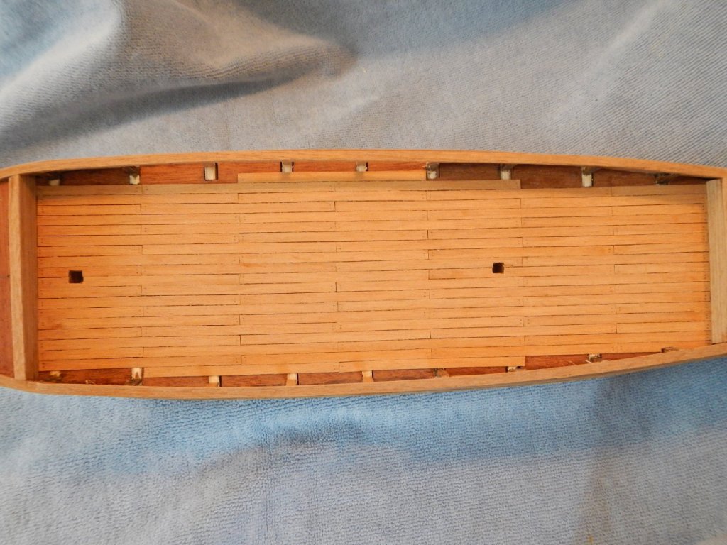
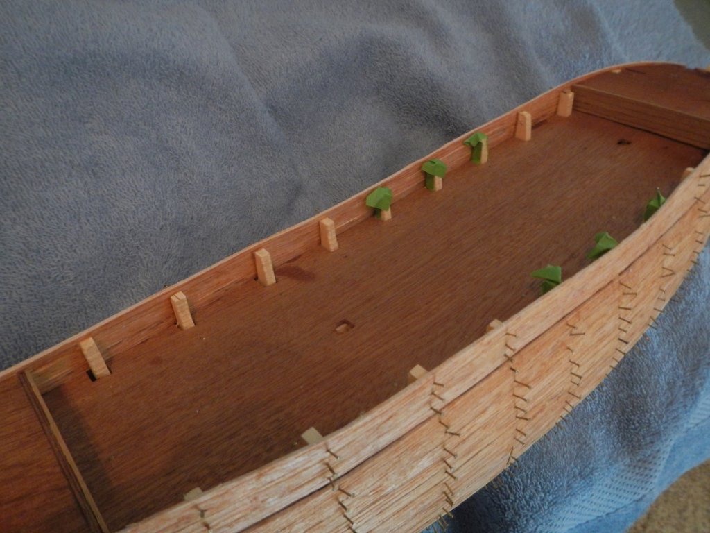
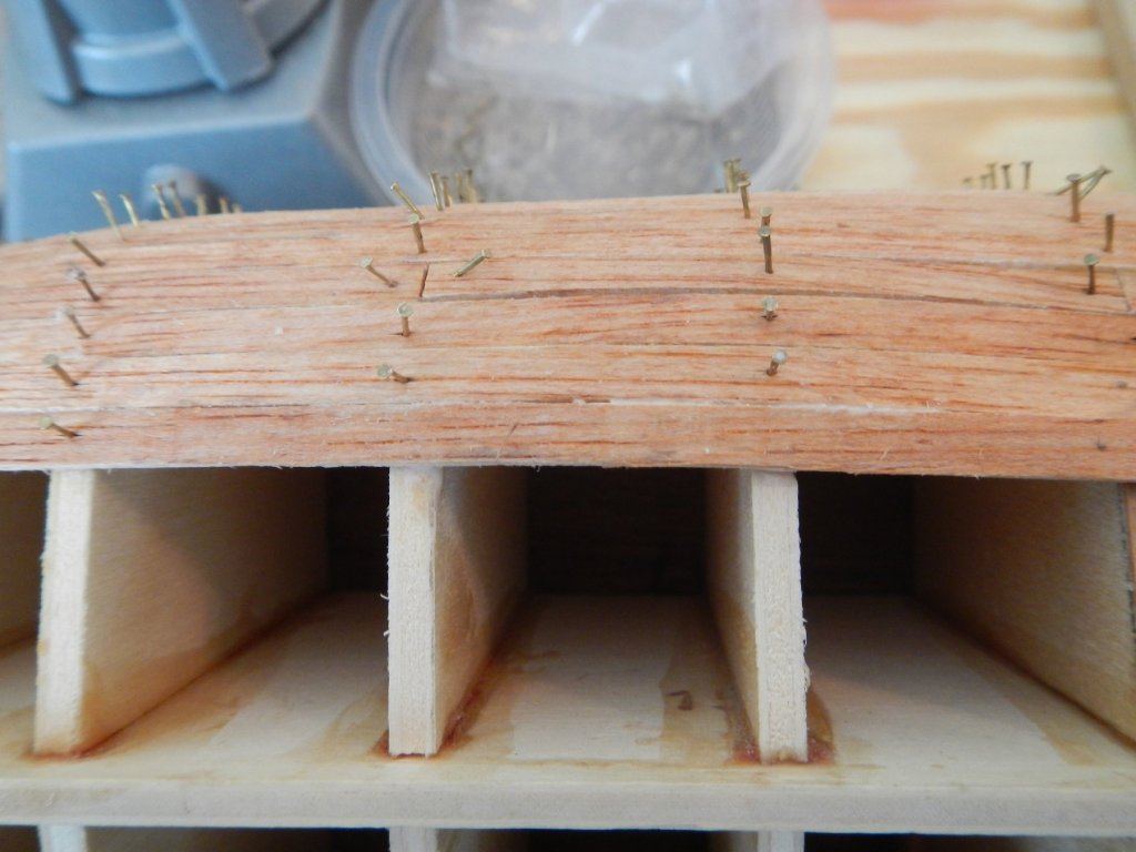
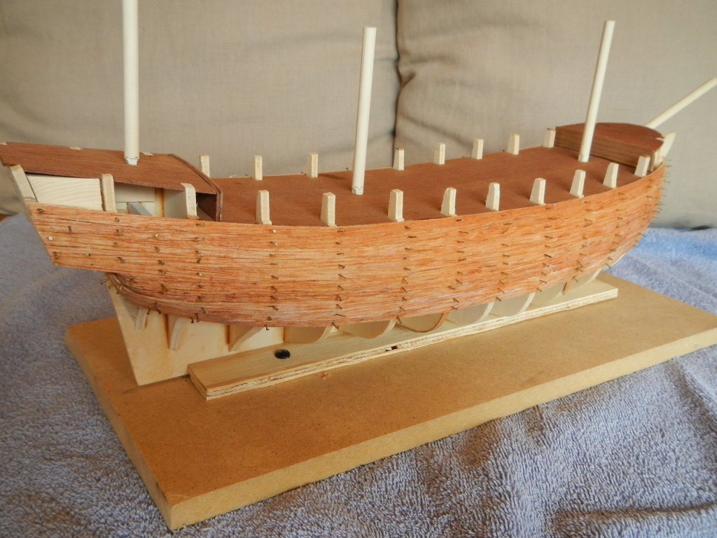
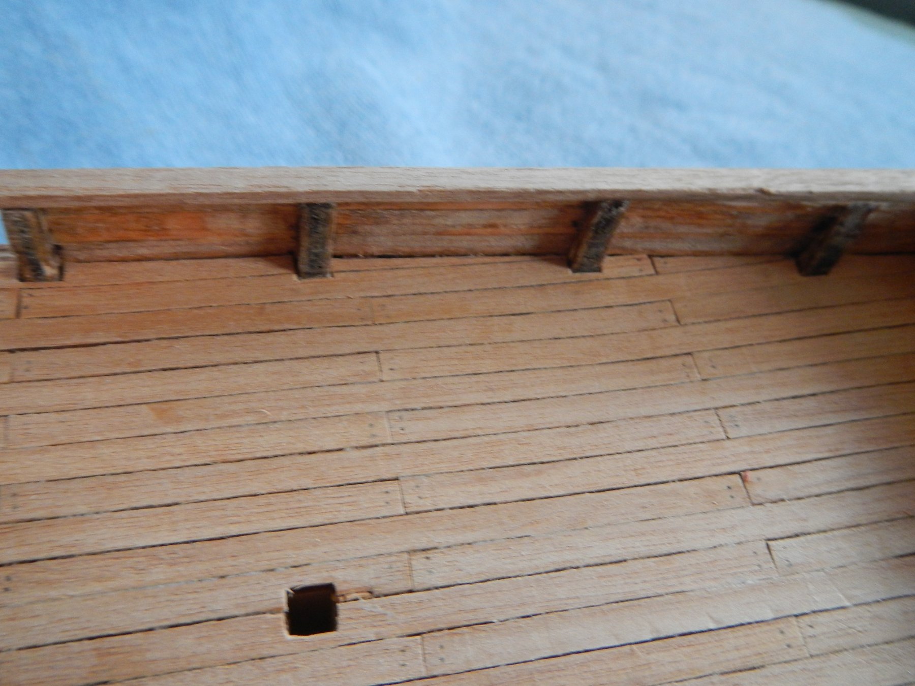
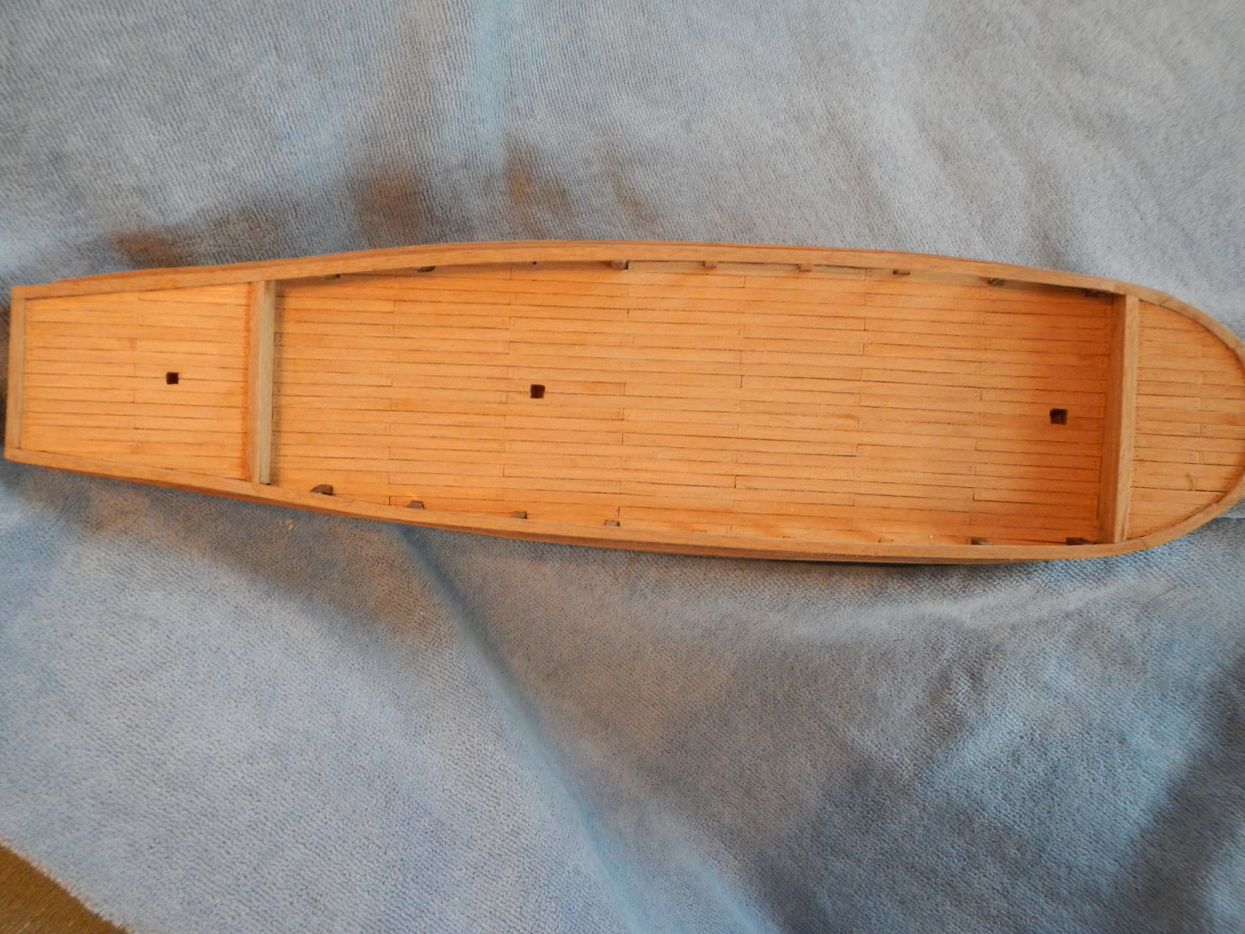
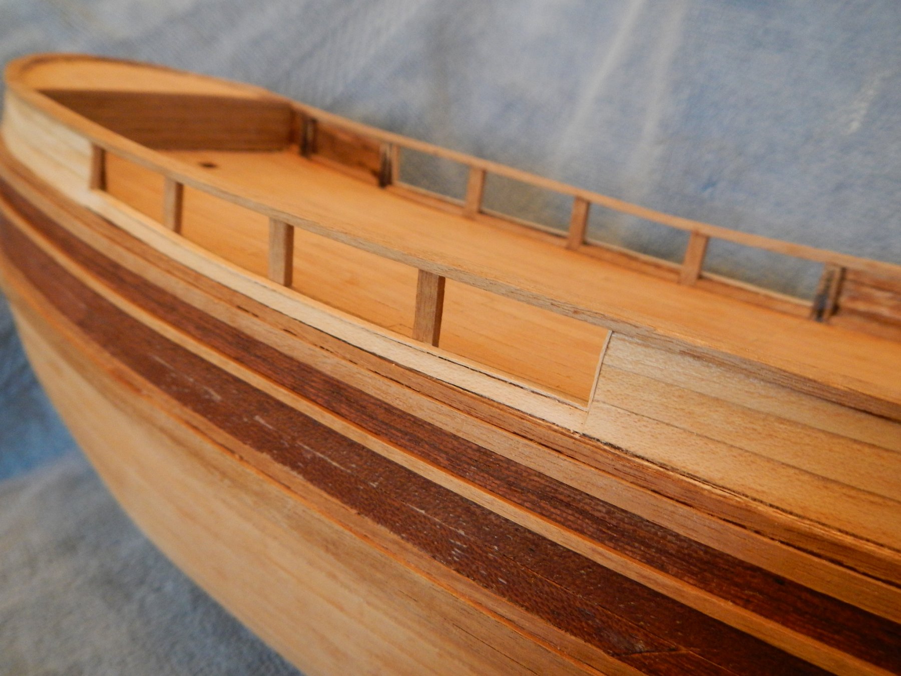
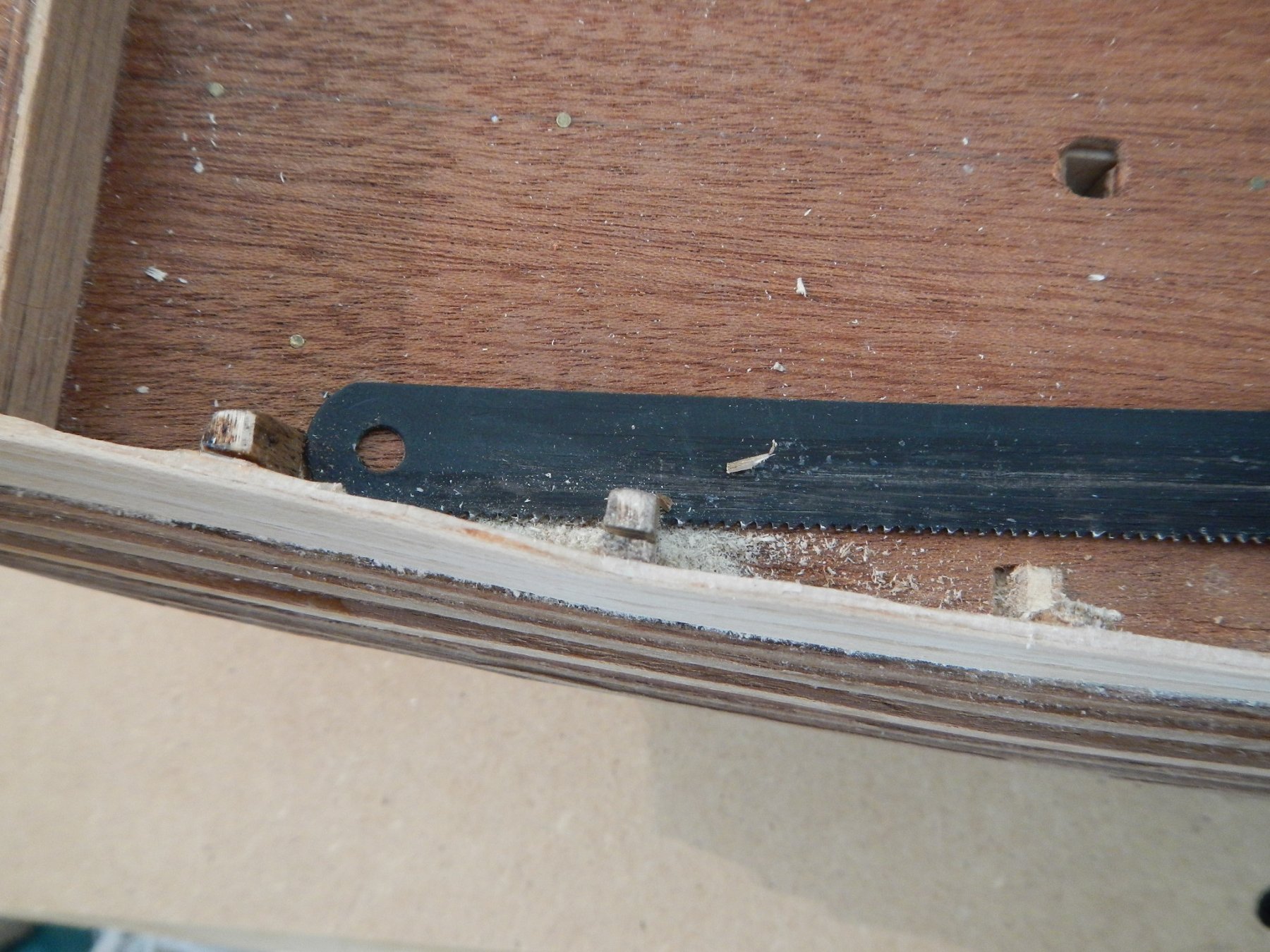
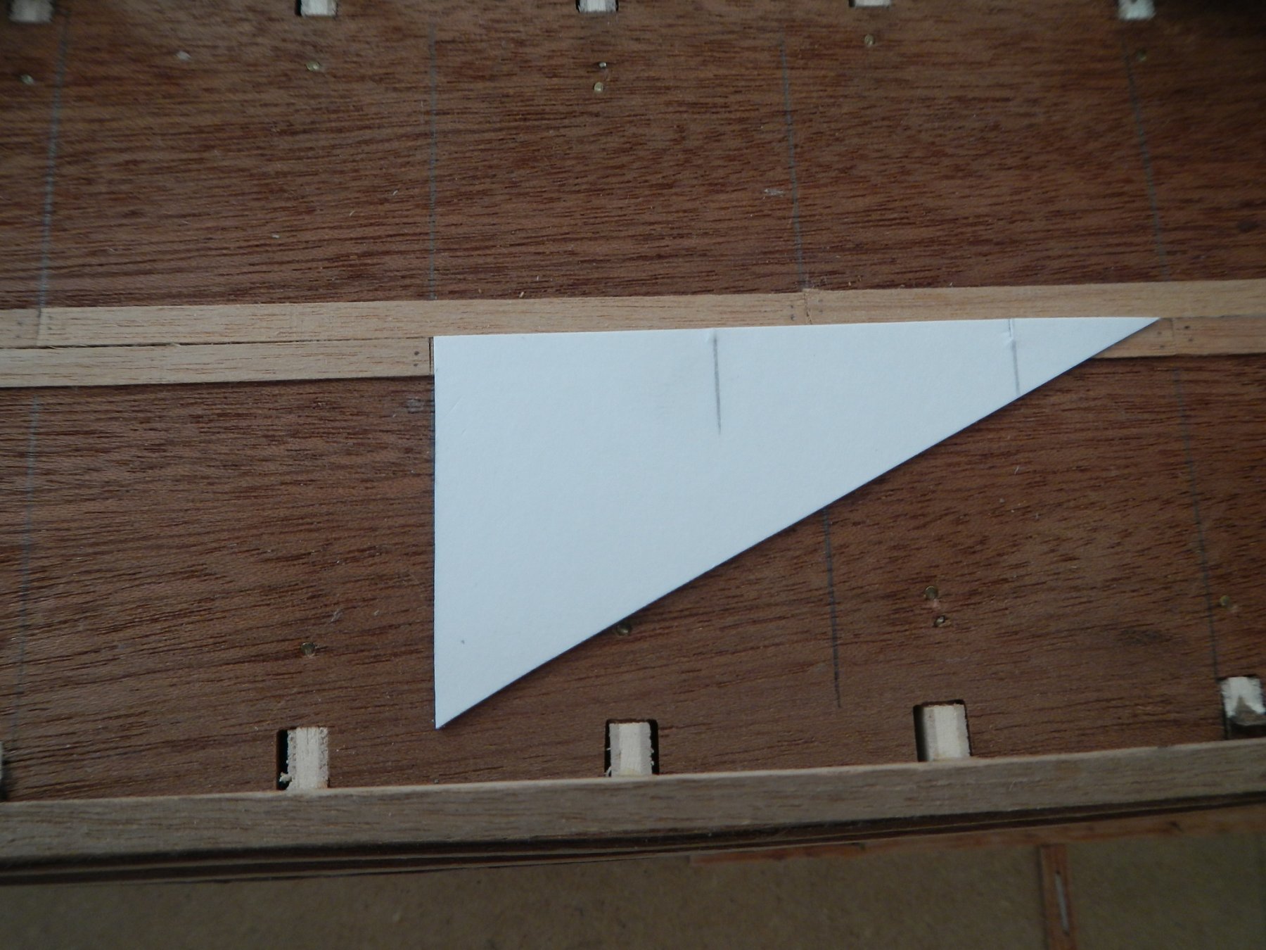
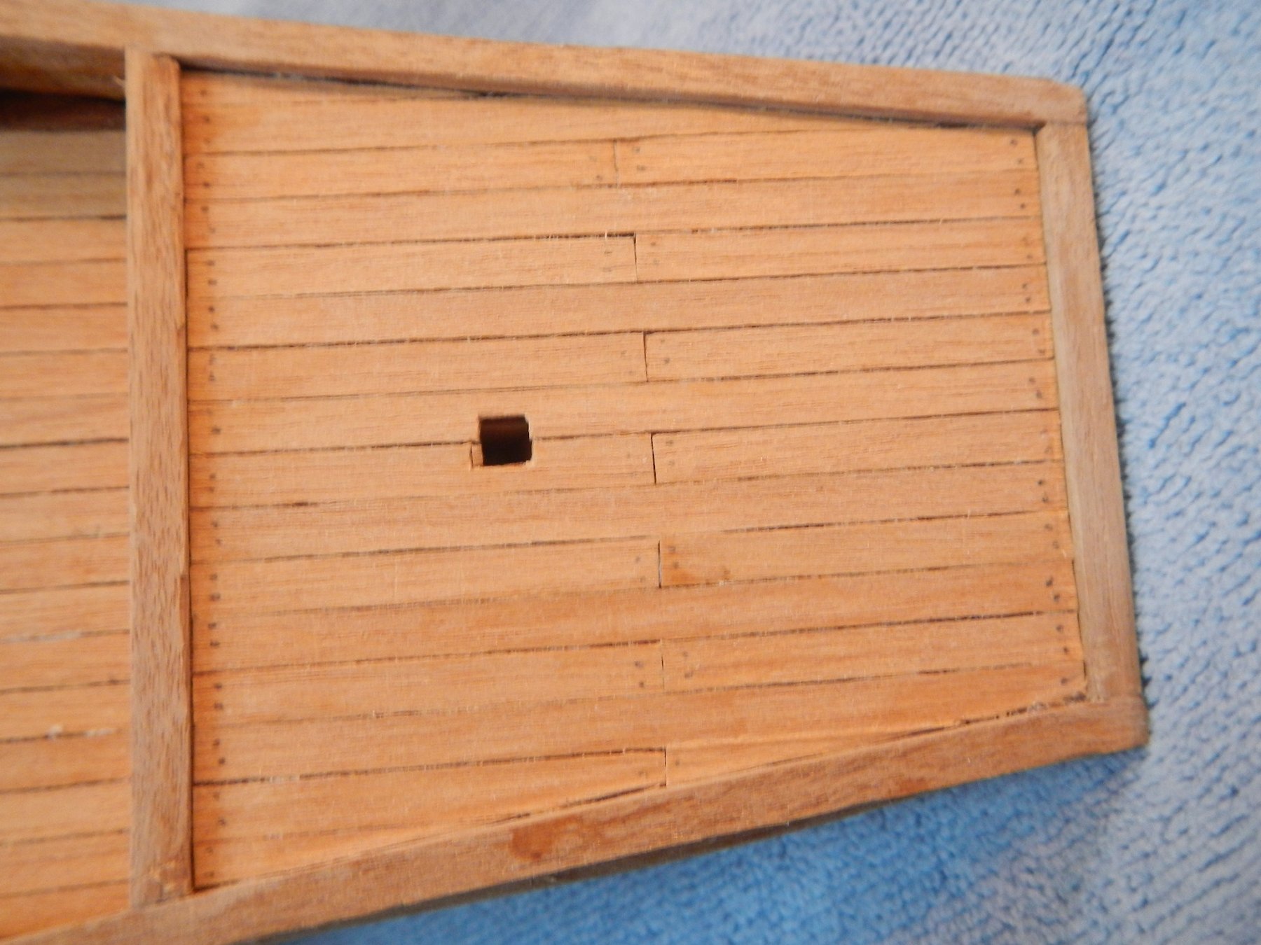
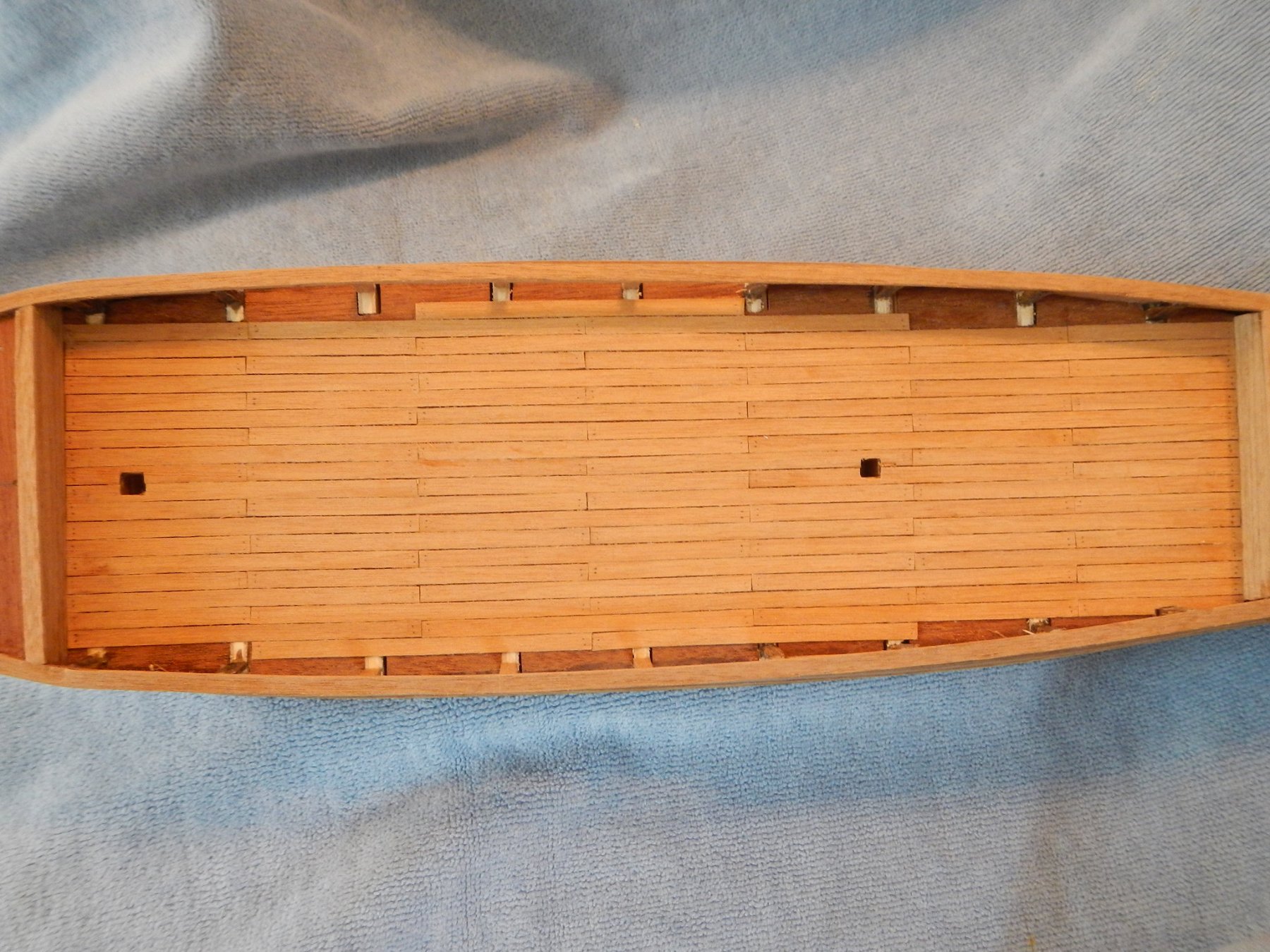
10/19/18 Happy Thanksgiving! This is a special post to recognize 200 hours of effort so far on the Beagle. In this entry I opened up the bulwark between frames 4 and 8, added the railing and started planking the decks. I found that for this work, the best way to hold the hull was to put it on the keel stand, but put the bow in the vice to stabilize the hull for the work. As I opened up the bulwarks, I realized that the original intent of the kit was to have the deck below the level of the step that defined the bulwark on each frame. Unfortunately, the way the frames were cut the top of the deck came out even with the step. I decided that I would complete the work on the deck, then add a small section of bulwark at the bottom of the openings between frame 4 and 8 to conceal the interior deck construction. This will be done in the next phase. Before installing the railing, I trimmed back the frame extensions to about 1 – 2 mm. The instructions suggested doing this after the railing was installed, but I thought it much easier to do before the installation. I found the best way to do that was to use a hack saw blade, as it is flexible enough to work down along the bulwark. I then added railing around the perimeter of all decks, piecing the fore deck to match the curve of the hull. To ensure that the rail was in the proper position over the open portions of the deck, I rigged a segment of bulwark (previously removed) to the standalone frame extensions with a rubber band. Also, to try to ensure the 1 mm overlap of the railing over the bulwark, I used a piece of 1mm lath laid on the bulwark when gluing the railing. After the railing was installed, I washed the joints with diluted glue and sanded the railing to fill in the joints. Tip: Since there is very little to hold the railing in place, it is very important to take the time to bend the railing, both horizontally and vertically, so get an exact a match as possible to the compound curve of the hull. Once the railing was in place, the frame extensions of frames 5 to 7 were removed. Again, I used the hack saw blade, since it was flexible enough to lay flat on the false deck to cut off the frame extensions. With the railing in place, I was ready to start on planking the deck. I built two jigs to help with that. The first jig had an 80 mm length on one side and a 40 mm length on the other. Combined with a straight edged side cutter, it was easy work to prepare the plank boards. The second jig was used to add holes at the end of the planking to simulate nails. I put two tacks in a couple pieces of poster board, taped them together, then mounted them on a wood platform high enough to get the planking under them. By pressing down on the nails, I could quickly add the holes. I then highlighted the holes with a pencil point, and ran the pencil around the edge of the planking to help define the edges when assembled. To help ensure that the plank ends stayed in alignment across the deck, I made a small right triangle out of poster board and used it to mark out the joint lines on the deck. The decking itself went on pretty easily. It was fascinating to see yet another compound curve as the main deck is concave fore to aft and convex from the center to either side. It makes a lot of sense to managing water on the deck, but I wonder what it must have been like to walk along the deck that was continuously sloping. [A side note: We were in Carmel-By-The-Sea recently, and I stopped in at a nautical shop that had a number of models. I examined them with great interest, but one thing that struck me immediately was that the decks were flat!] I finished the bridge deck completely (hurray!) and main deck, except for piecing around the perimeter. I will do the fore deck last. Build time to date – 201.25 hrs: 19.75 hrs for the work in this build log entry. MSS - Model Shipbuilding Simplified by Frank Mastini

-
Thanks for your kind comments. It has been tough at times to keep from pushing through to get on with the next part of the build. However, I am thoroughly glad to be done with the hull after spending over 180 hours on it. It doesn't look like anything else (with the possible exception of the rigging) will be as labor intensive.
-
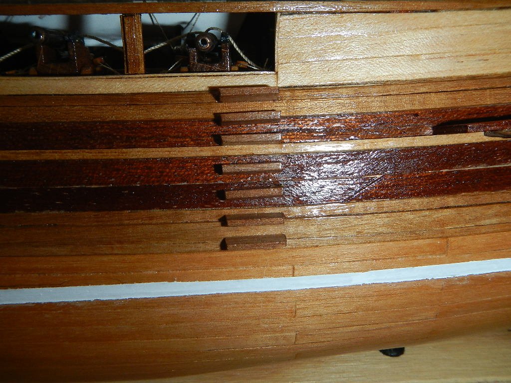
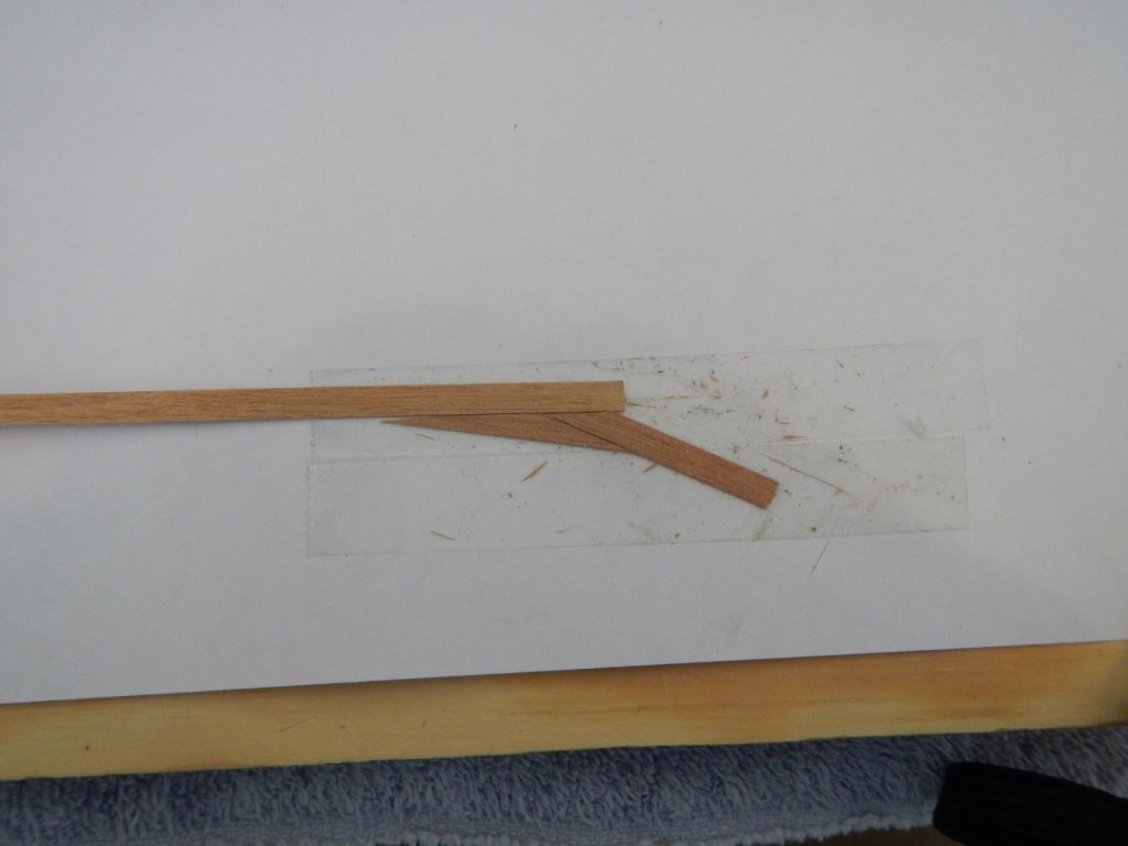
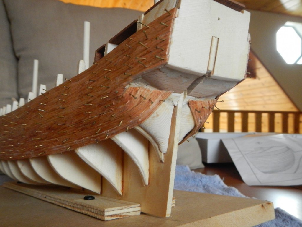
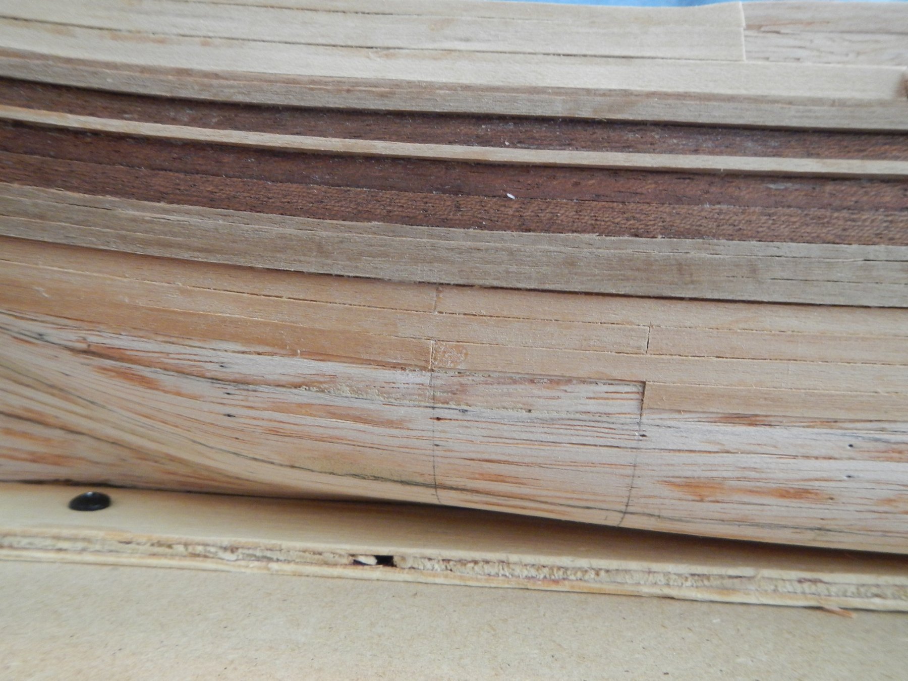
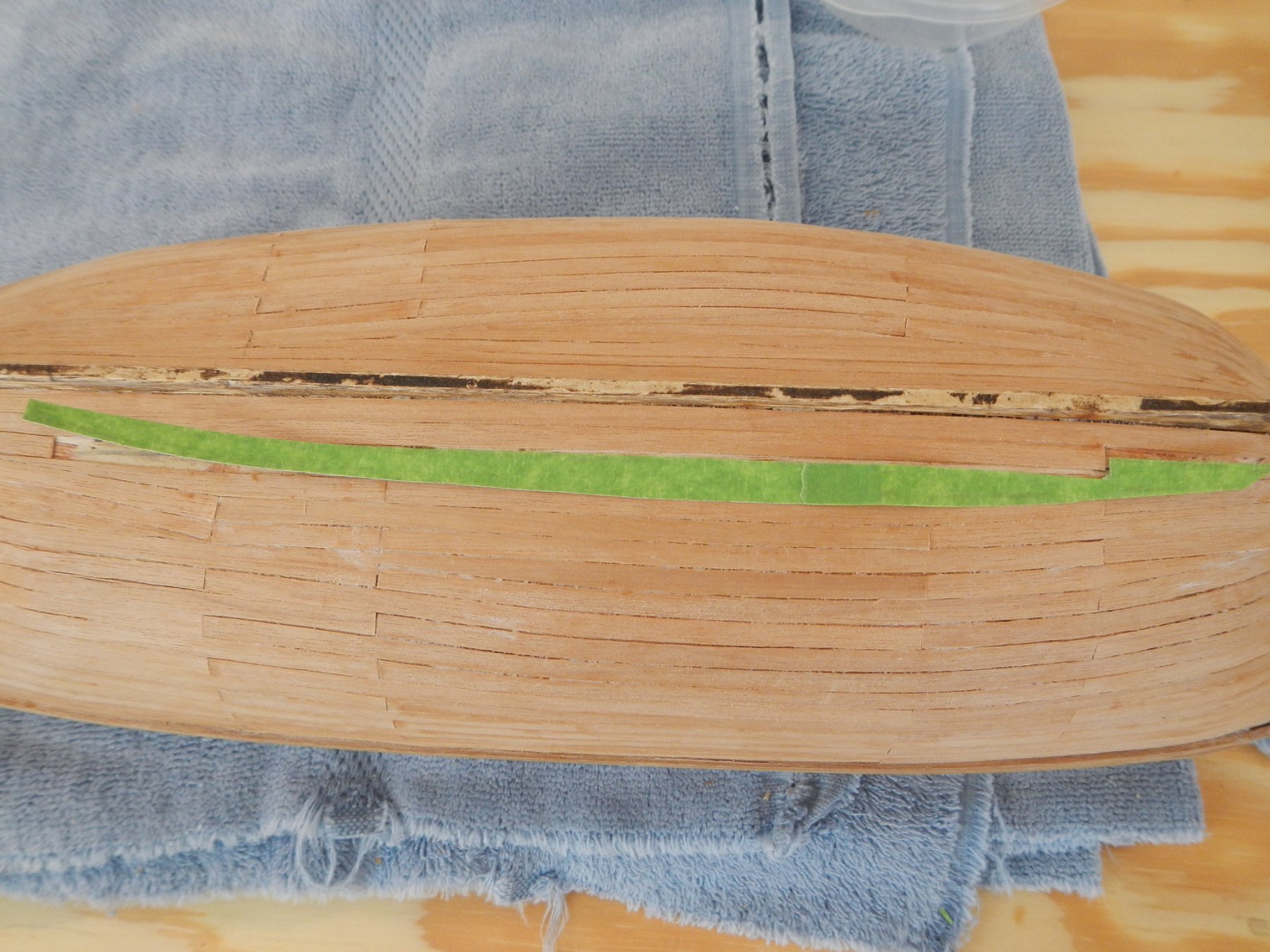
10/19/18 This post covers the work done to finish plank the hull. I first planked the stern followed by the sheerstrakes, decorative (I think) planking and bulwark on the starboard side. I then worked my way down the starboard side of the hull. At the recommendations from other members of this site, I read all the articles on planking available in the Articles Database getting a much better understanding of the task before me. I am constrained in that I am determined to use the materials provided to complete the ship and, therefore, could not cut planks out of a wider plank of wood as recommended. I therefore interwove planking coming around the bow with the planking from the side for each row. This is not perfect, but it is a significant improvement in appearance over the way the underplanking turned out. I did each row of plank in three segments: 1) From the bow to Frame 4 or 5 (alternatively) 2) From Frame 4 to Frame 8 or from Frame 5 to Frame 9 3) From the stern to Frame 9 or 8 (alternatively) This allowed me to do the detail work at each end of the ship, while taking advantage of the relative evenness of the center area of the side. I used the method shown in one of the Planking articles for creating custom cuts of planking. I lay masking tape of the opening, trace out the opening in pencil, transfer the tape to paper and cut out the tracing. This can then be used to create the appropriately shaped piece. TIP: Use double-sided tape on paper to provide a holding table while working on shaping the planking. I used the gluing method recommended in MSS for finish planking. I used Superglue at the beginning of the plank, then applied carpenters glue over about 1 to 1 – ½ frames. While holding the wood in place, I then ran the plank bender over the glued plank. This pressed down the plank while steaming it and drying out the wood glue to adhere the plank to the underplanking. I also found that if there was a small gap, moving the plank bender perpendicular to the current plank and toward the previous row would help close the gap. I kept a wet rag handy to wipe up any excess glue before it dried. Once I completed the planking, I went back over each section applying a wash of diluted carpenters glue to seep into any openings or gaps. I then wiped off the excess glue, dried the planks and sanded the surface with fine sandpaper. This allowed the sawdust from the sanding to adhere to the glue in any openings providing a smoother finish. After completing the starboard side, I did the same thing on the port side. For the port side, I was short of material for completing the sheerstrakes and decorative planking out of the kit. I had to splice one of the rows of mahogany planking on the port side. I cut the plank on a 45-deg. angle to reduce the visibility of the splice. Also on the port side, I substituted a 2mm x 2mm + 2mm x 4mm walnut sheerstrake for the 2 – 2mm x 3mm walnut pieces that were not in the kit. I then completed the planking on the port side. After completing the bulwark, I trimmed it to the top of the frame extensions. Since this kit does not provide the material for the interior of the bulwark or encasing the frame extensions, I decided to at least stain those areas so that they would be closer in appearance to the rest of the material on the deck, in case I am unable to cover them. One of the reasons that I wanted to do a plank on frame model such as this was for the experience of bending wood to conform to a curved surface. I have worked with wood all my life as a rigid material, but I became fascinated with idea of shaping it into something of such complex curvature. It is not perfect, but I am happy with the way it turned out and glad to have had the experience. Now on to work on the deck. Build time to date – 181.5 hrs: 56.5 hrs for the work in this build log entry. MSS - Model Shipbuilding Simplified by Frank Mastini

-
Thanks, Eric and Antony, for the referral to the Articles Database. 👍 I downloaded all the relevant articles and reviewed them multiple times. My constraint is that I am determined to build this ship using the materials provided, which is incompatible to the methods discussed in the articles. However, I eventually decided on a hybrid approach of interweaving plank segments from the bow and side to cover the curvature of the bow. It is not perfect, but it seemed like a good compromise (see following article). Best, Dave
-
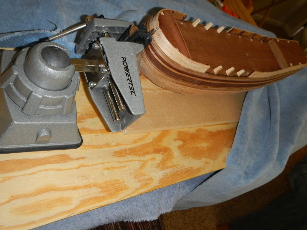
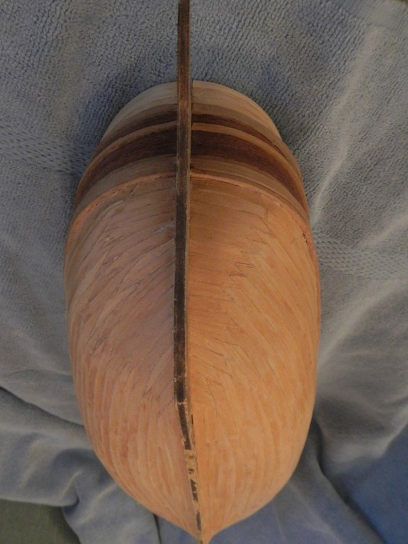
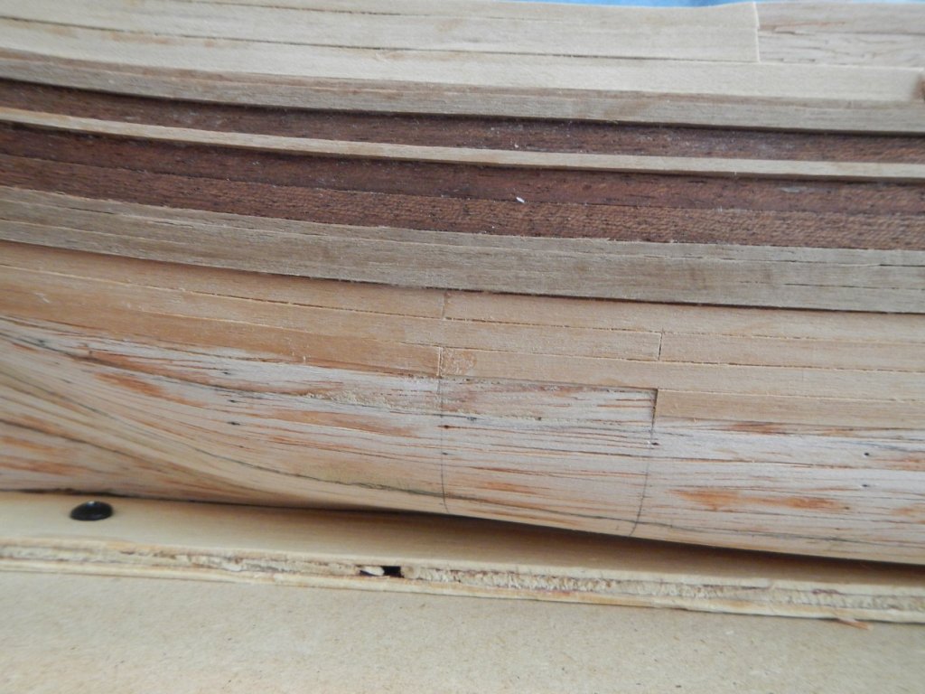
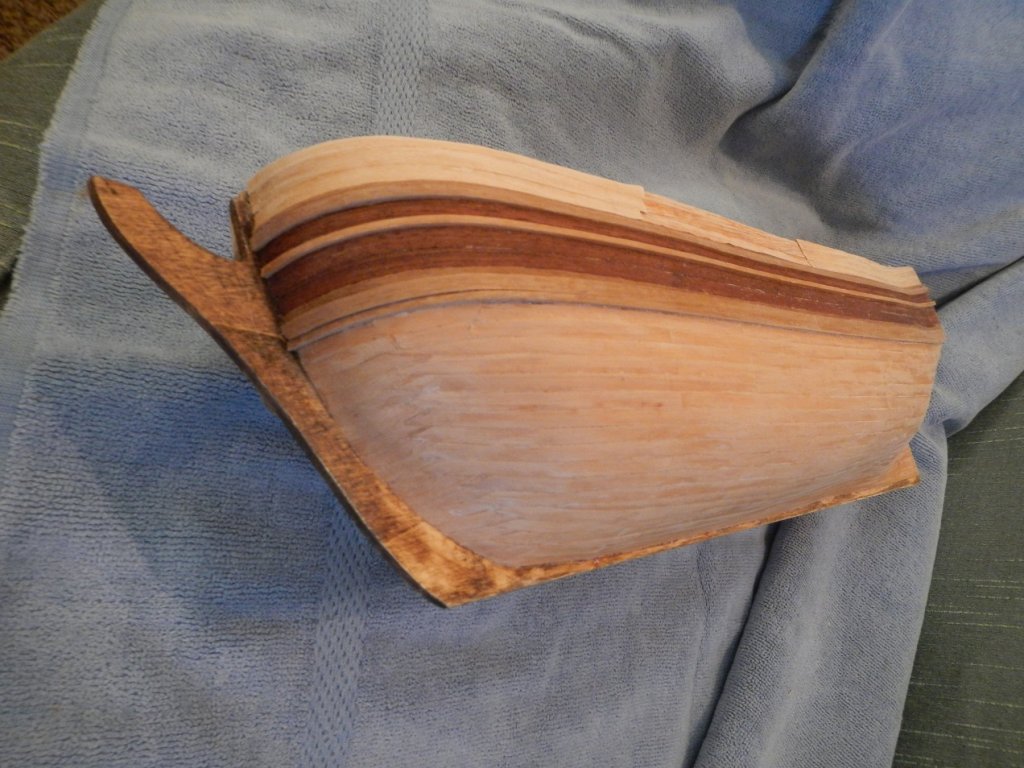
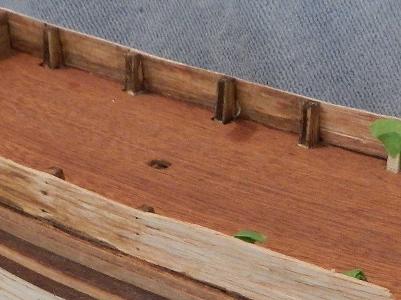
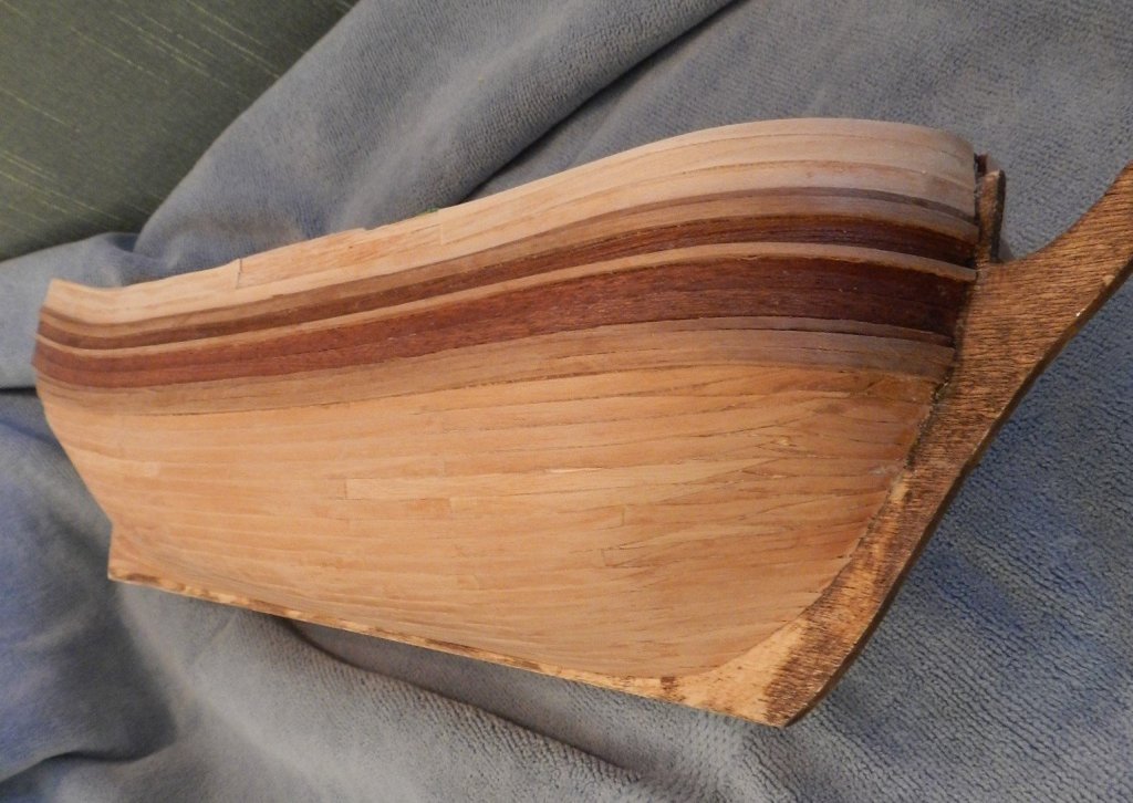
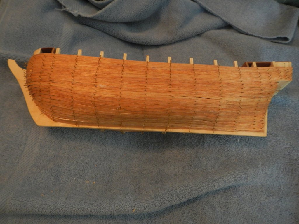
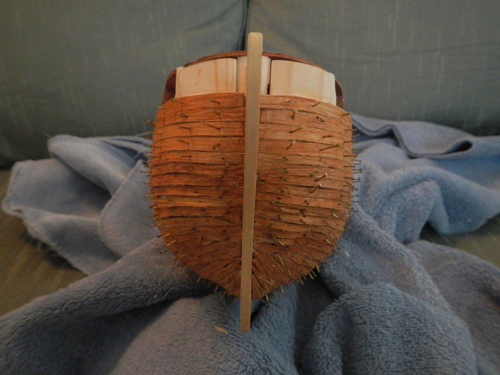
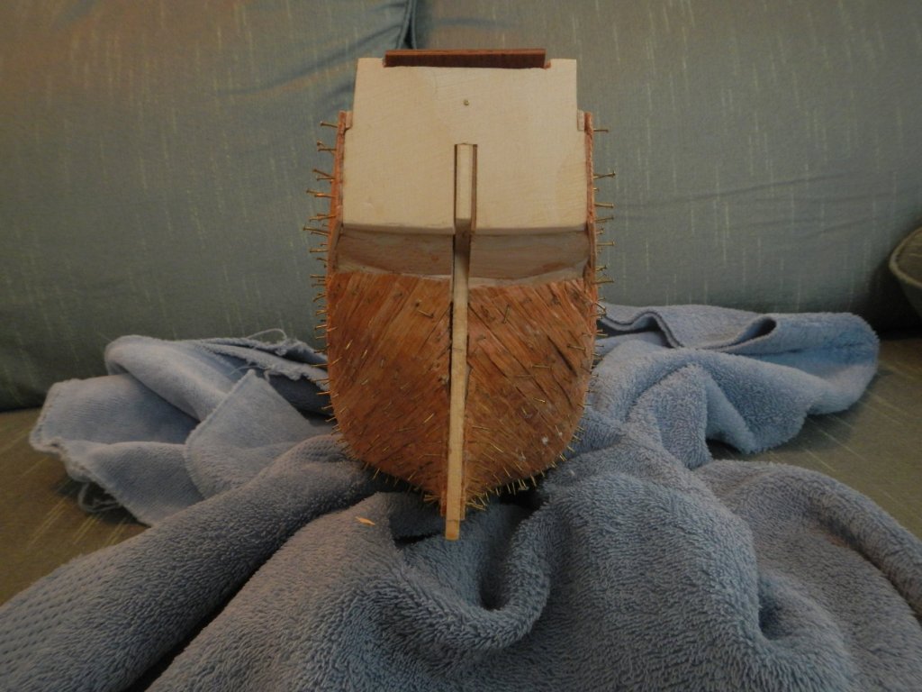
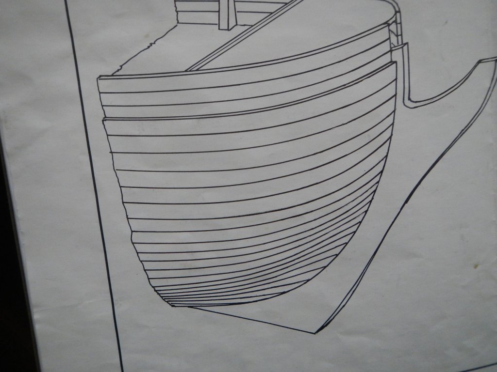
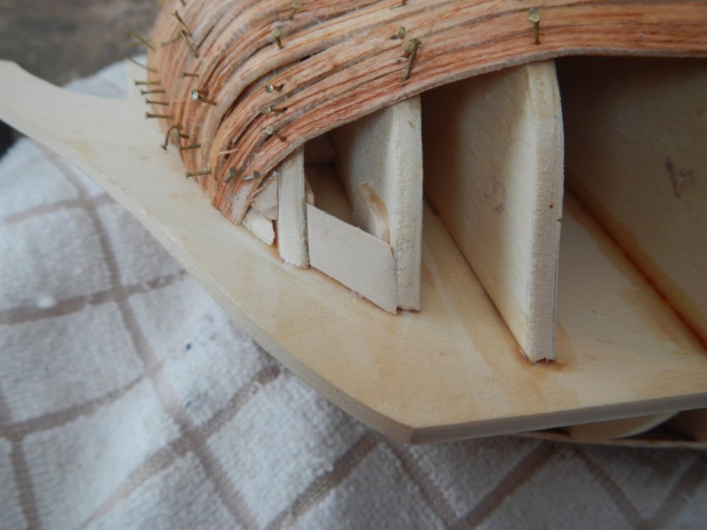
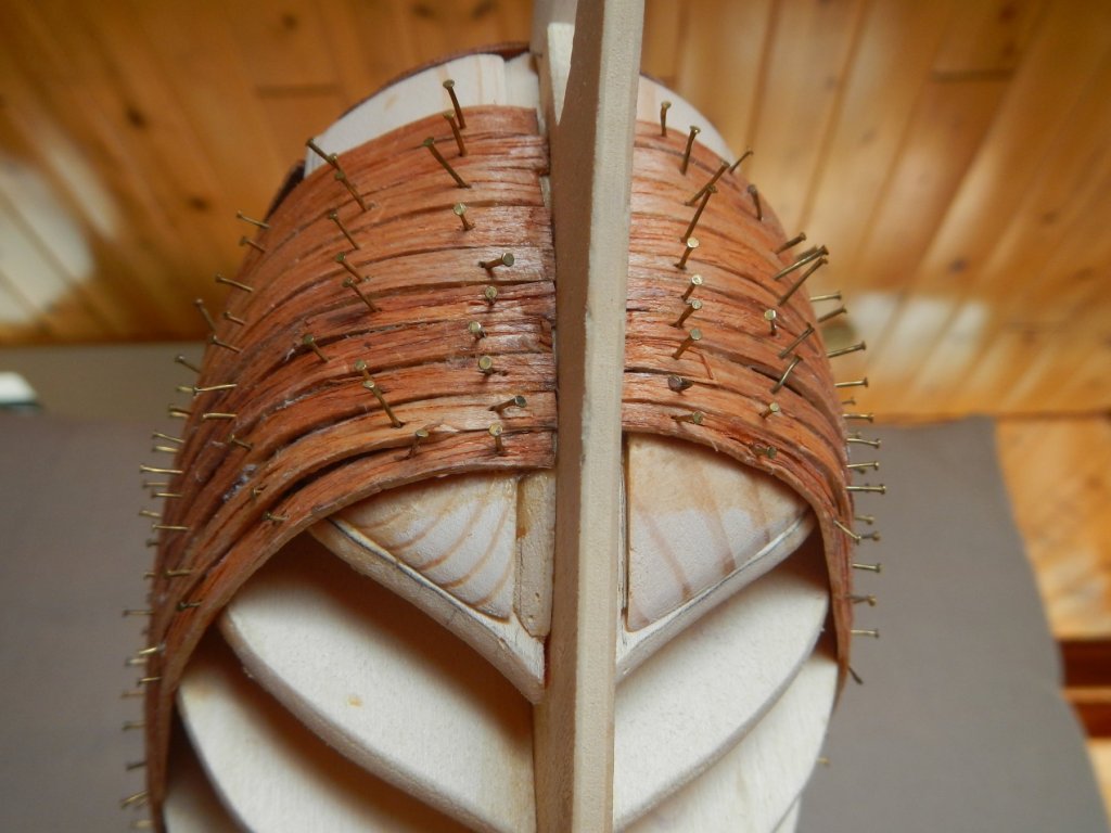
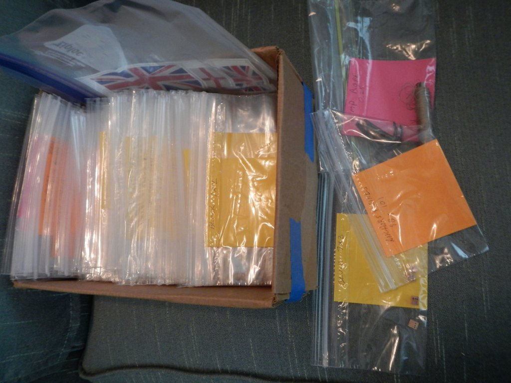
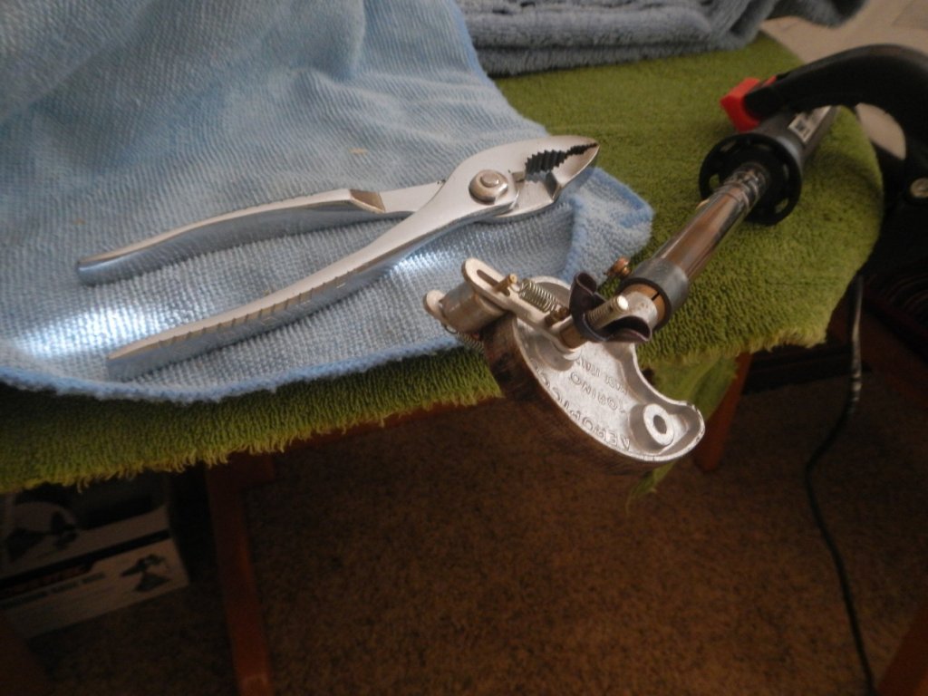
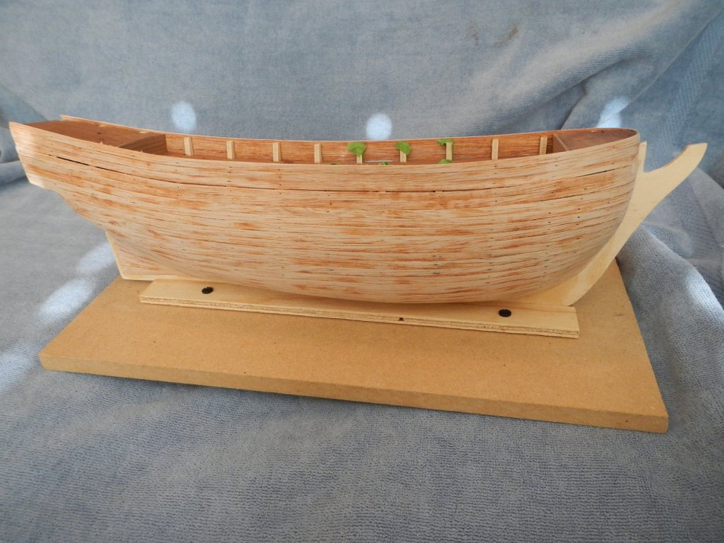
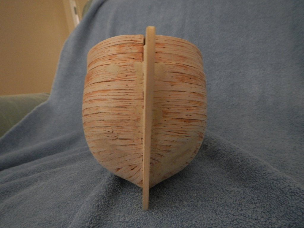
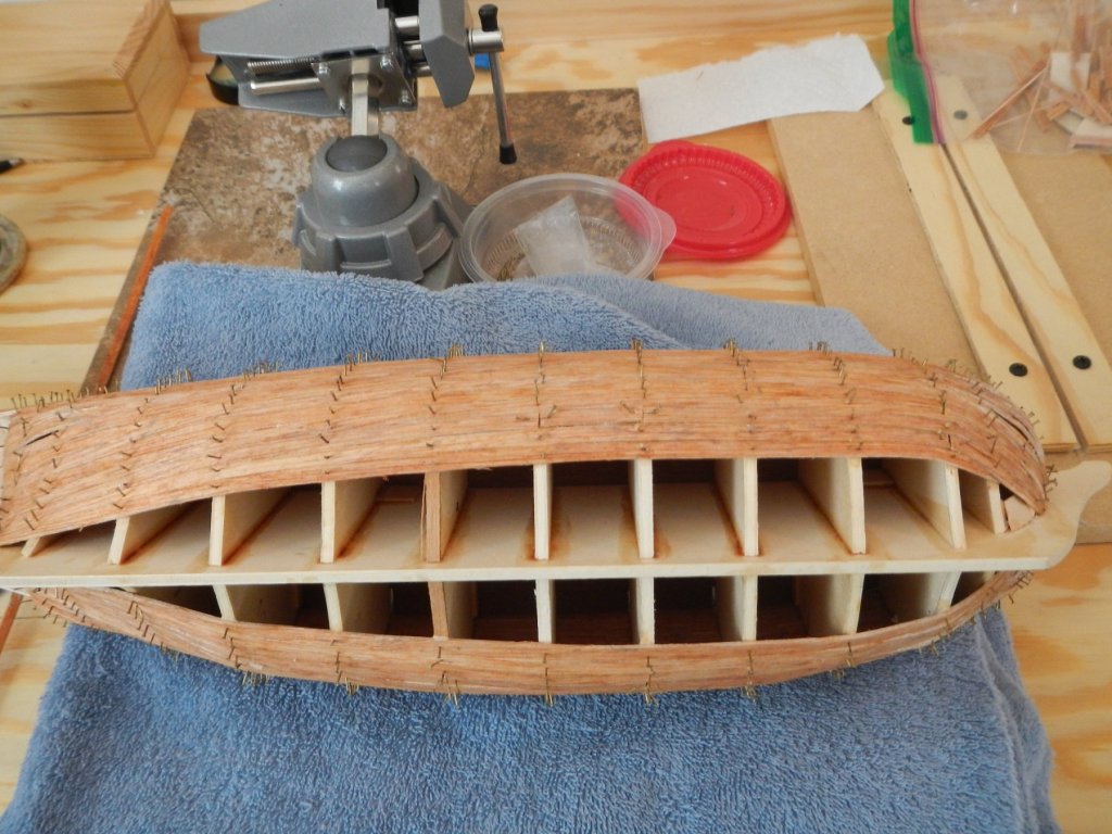
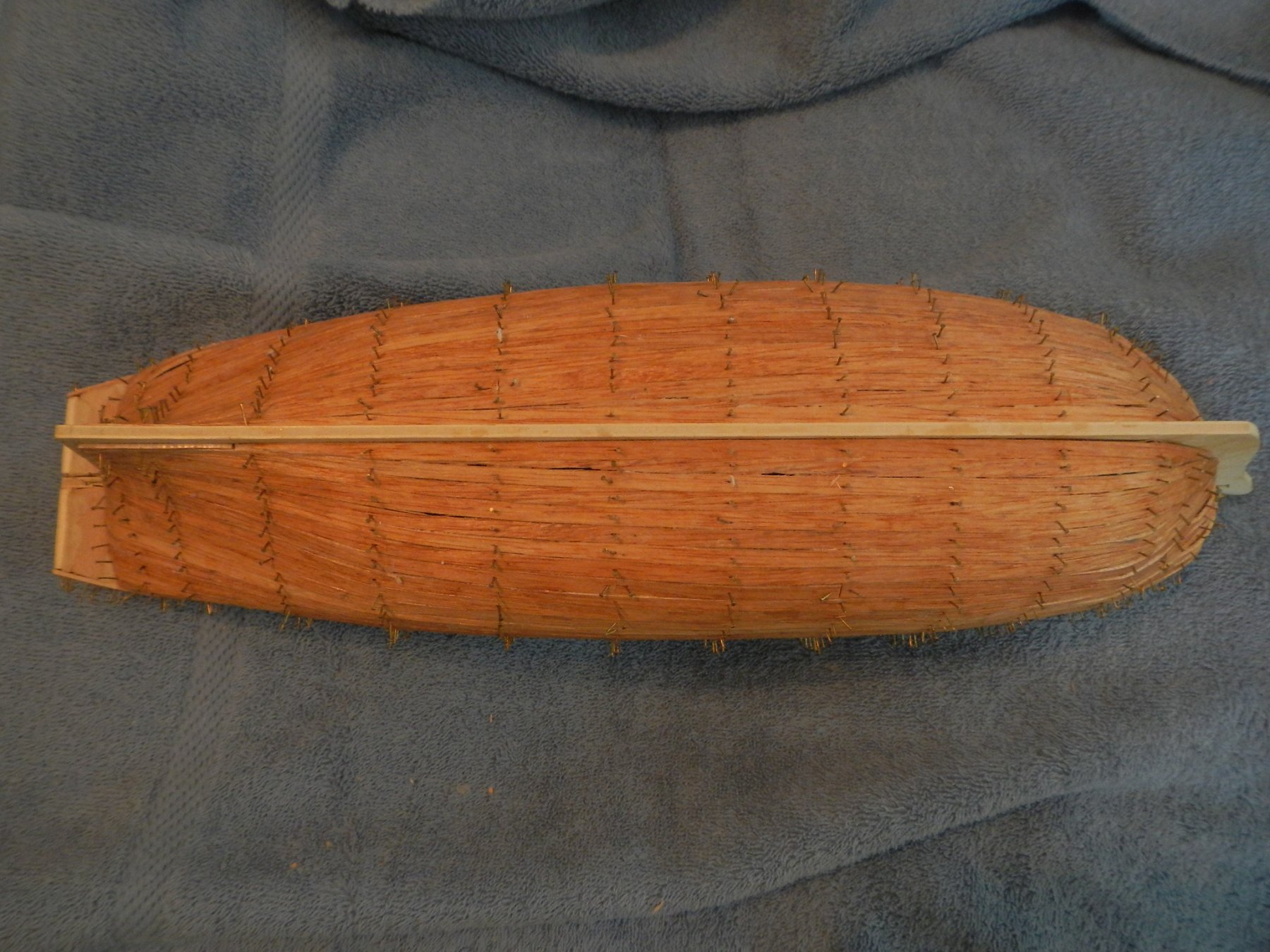
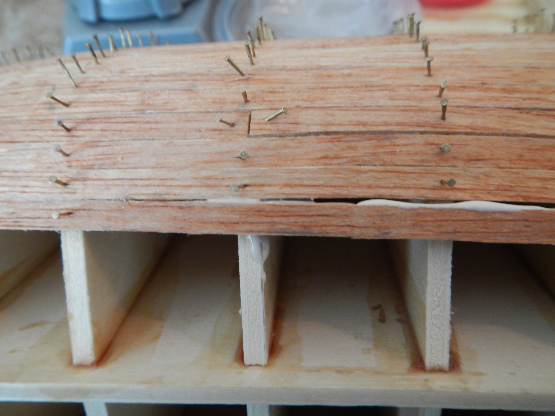
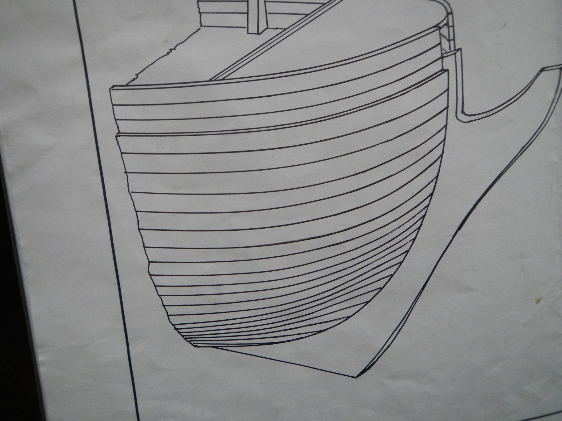
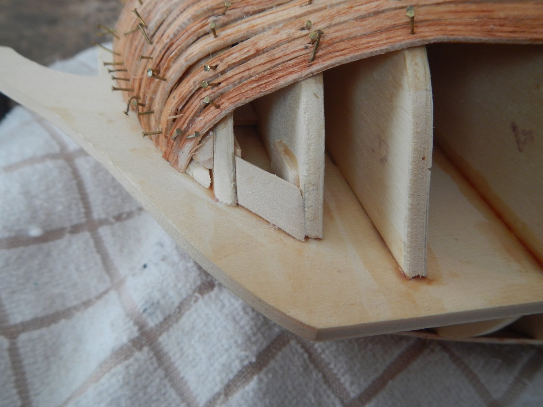
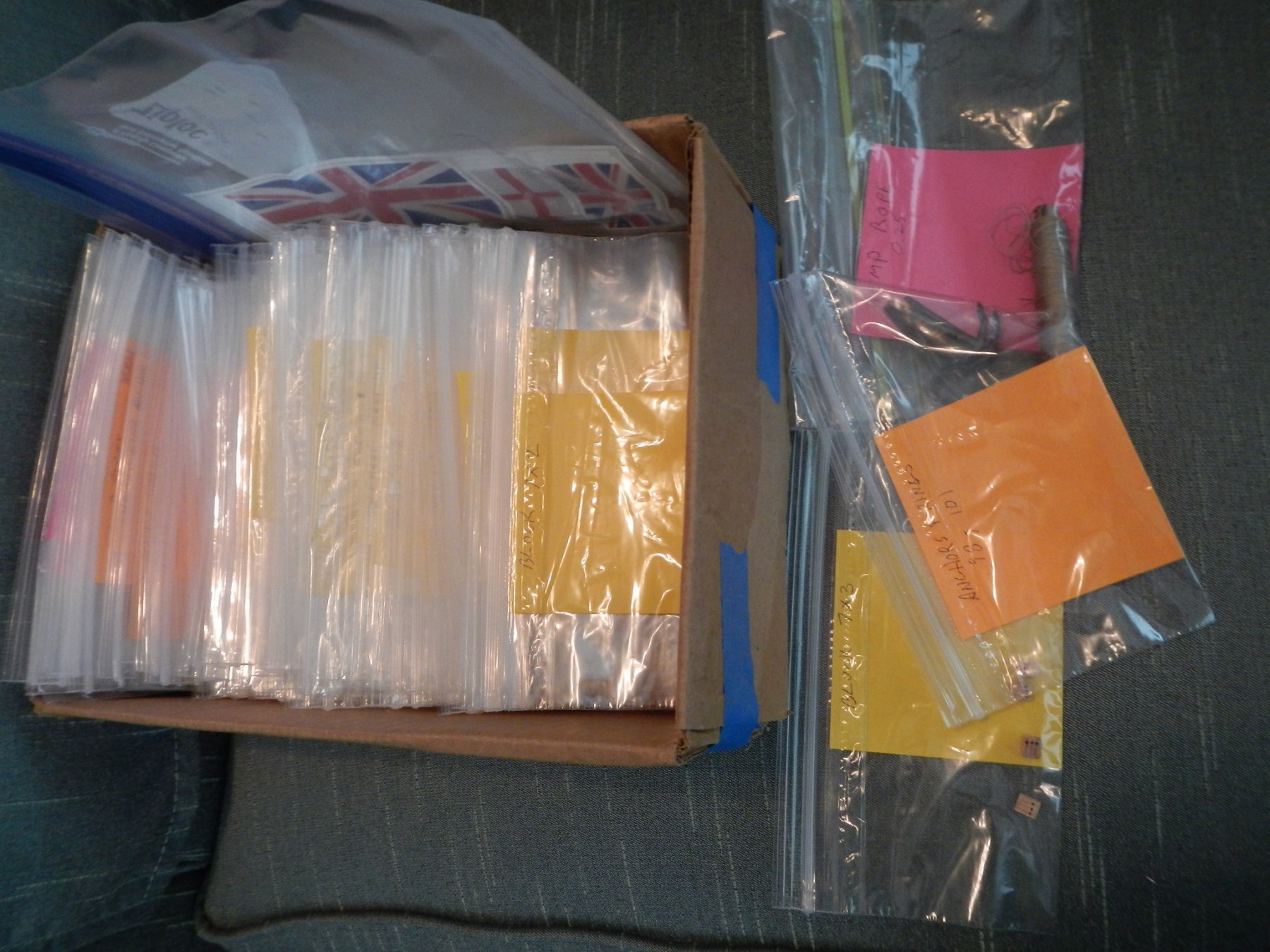
8/27/2018 Another item I had intended to include before is my parts inventory storage. At my wife’s suggestion, I used sandwich bags and Post-it Notes with a different color for each type of material (wood, metal, other). The parts are stored alphabetically by type. It works very well (at least so far!). This post covers the work done to underplank the hull. To soak the planks, I created a plank bath from a length of threaded PVC pipe. I cut it to a length slightly larger than the planks, then capped the threaded end. I used a slip cap on the other end to put in and take out planks. When done for the day, I would empty the pipe, then unscrew the cap so that the pipe could dry out. I used the gluing method recommended in MSS. I put wood glue on the frames and the top of the plank around the frames, and put Superglue in the middle of the top of the plank. However, I did two frames at a time, as opposed to the one suggested in MSS. I used the older version of the Aeropiccola plank bender as I thought the various curvatures available on the plank bender would be useful, which turned out to be the case. TIP: Have a plier handy to pull the roller out for inserting the wood and moving the roller up and down the curved surface. Overall, the planking went well, except for the bow area. The picture in the instructions showed the planks going across the bow horizontally. However when I tried to do that I found it difficult, if not impossible, to get the planks to lay flat against the frames. After some online research on other builds, I decided to angle the planks as I worked down the rest of the hull. This worked much better. Because of this I added an additional landing block to the bow. I generally held the hull in the vise when I was laying the planks. However, as I neared the bottom that was impractical. I found that a folded bath towel provided enough cushioning while holding the hull in place while I worked. Here is the completed underplanking of the hull. (Looks pretty rough, huh?) Once the hull underplanking was completed, I worked up the bulwark extensions to underplank the bulwark. I decided to leave the nails in as I worked down the hull and up the bulwark, hence the hedgehog appearance of the finished hull. Once all the underplanking was finished, I removed the nails, sanded the hull and filled where necessary. I made four passes over the hull – rough grit, medium grit, fine grit and 0000 steel wool. (Looks MUCH better!) Now I am ready to begin applying the finish planking. Build time to date – 126 hrs: 33.25 hrs for the work in this build log entry. MSS - Model Shipbuilding Simplified by Frank Mastini


-
Thanks Graham and Eric for your comments. I think it is a very doable model, as long as you don't solely rely on the instructions provided. I like the idea of the PVC sections. I decided to do my lumberyard that way as I was moving between a summer house and main house. My approach allowed me to package everything up quite readily.
-
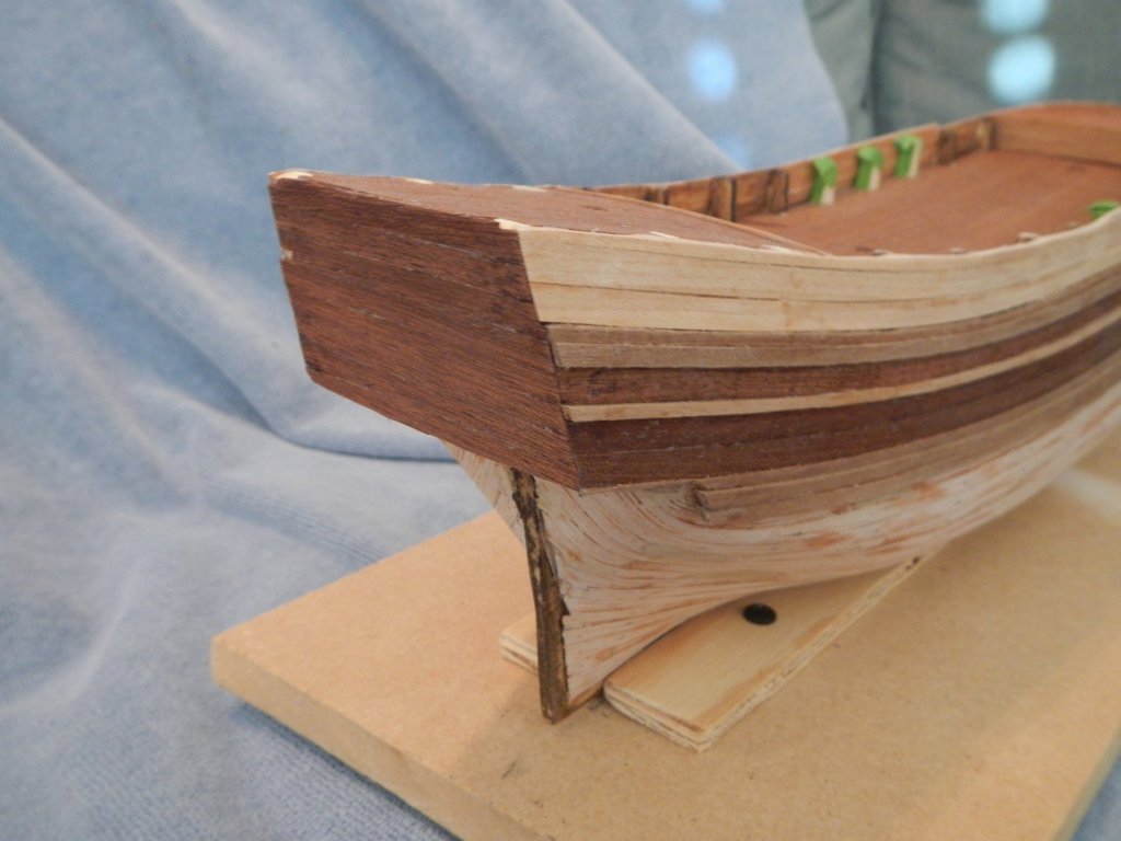
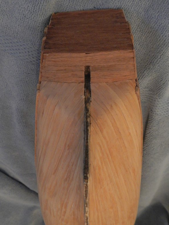
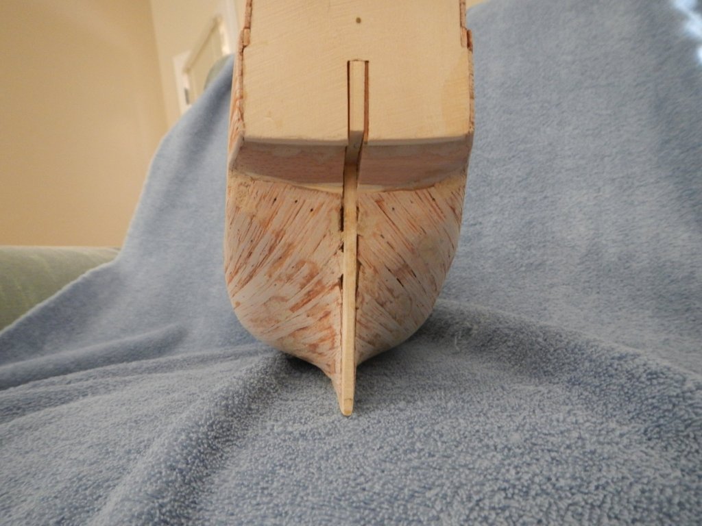
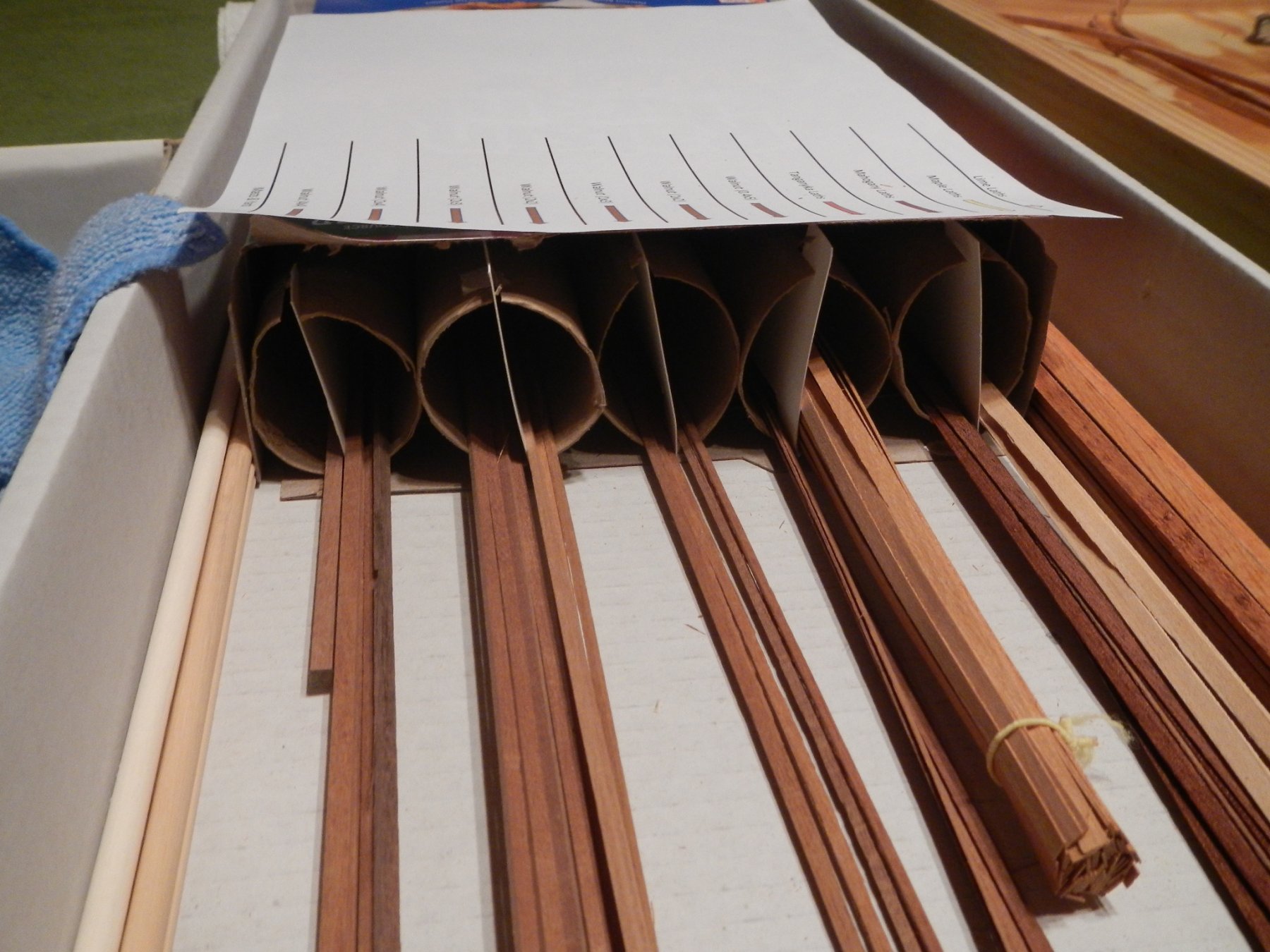
7/4/2018 Something I forgot to put into my last build log. I created a lumberyard from a cereal box and paper towel rolls with poster board separators. It works really well to sort out the various laths used in this model. This post covers the work done to add the false decks, the bow and stern walls, the plank landing blocks and fairing the hull. After stripping off the poster board false decks, I fitted the false decks for the foredeck, the main deck and the bridge deck. I then glued down the decks and nailed down all the decks to the keel and frames. I had to add a block on the foredeck starboard side to pull down that side of the foredeck. I planked and added the the bow and stern walls. I ran a pencil along the edge of the planks to bring out their definition. A large segment of time was spent in forming the plank landing blocks for both the bow and stern. These were recommended by MSS to anchor the underplanking when planking the hull but not provided in the kit. I struggled a bit in fairing the hull as I couldn’t tell on the port side whether frame 7 was sticking out too far or that frame 8 was too far back. I ended up taking 5 measurements (A thru E) along each frame of frames 5 to 10 on both the starboard and port sides. I compared the measurements between port and starboard sides and found that, indeed, frame 7 need to be filed back about 1 mm on the port side (compare 6-7 on starboard side with 6-7 and [R}evised6-7 on port side). This brought both sides within a millimeter of being the same on both sides. I then mounted four underplanks on each side of the hull to help with fairing the hull (also recommended by MSS). I found 3 or 4 places that needed to be filled in. I am now ready to start underplanking the hull. Build time to date – 92.75 hrs: 28.25 hrs for the work in this build log. MSS - Model Shipbuilding Simplified by Frank Mastini


-
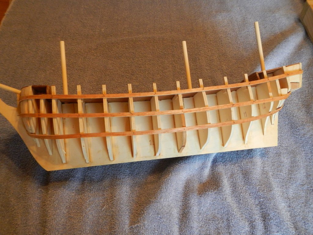
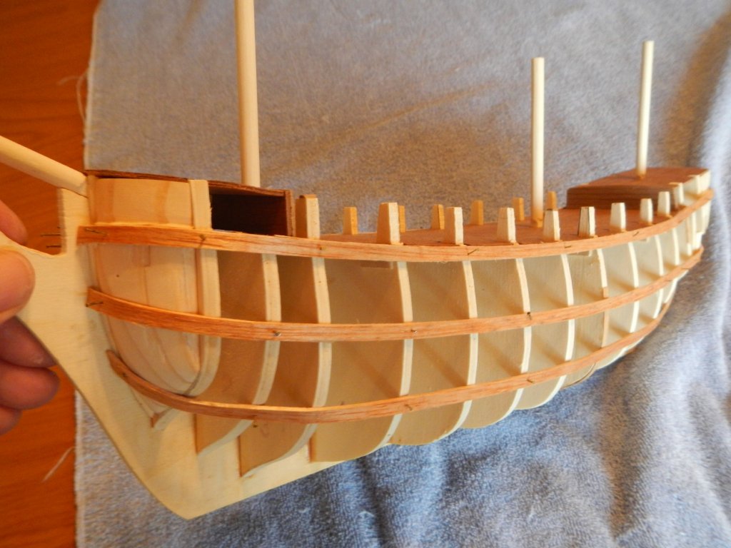
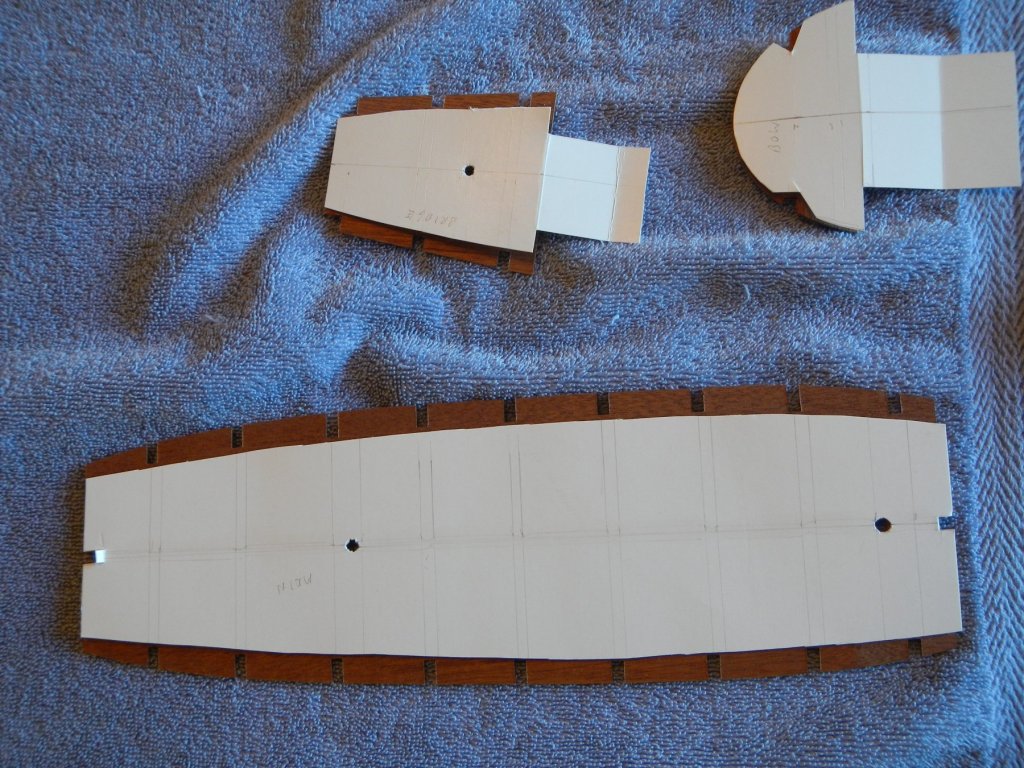
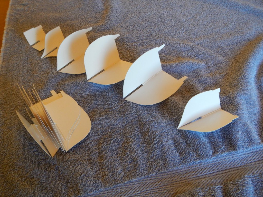
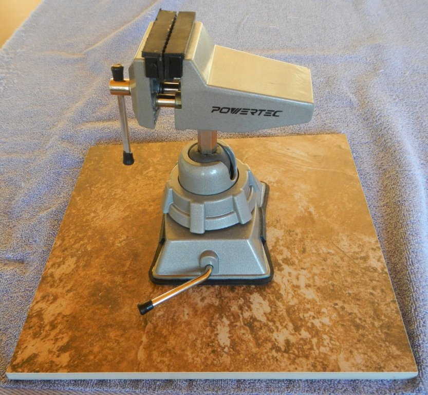
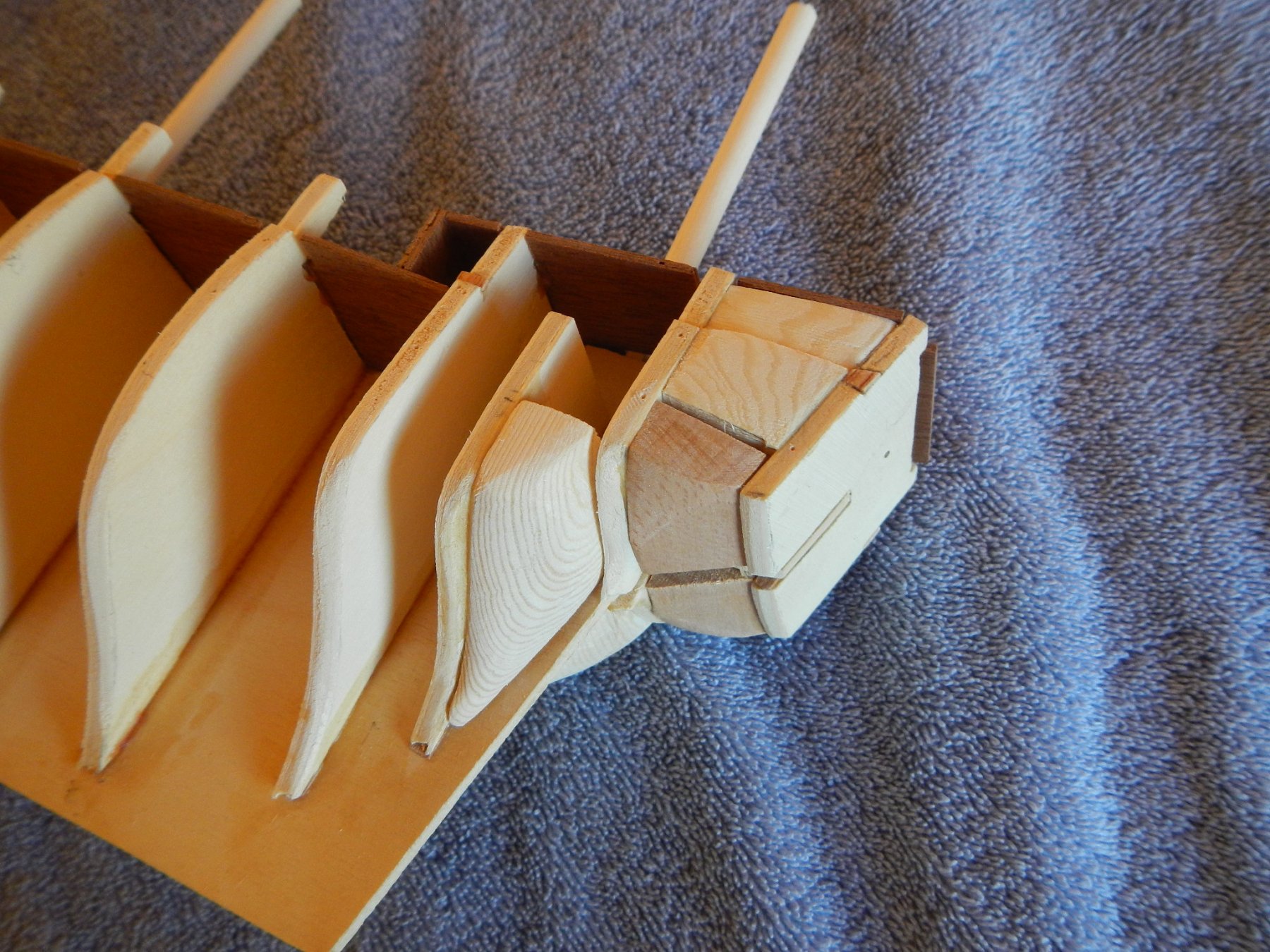
6/18/2018 This post covers the work done to prepare the keel and frames for gluing. Right up front, I want to credit Model Shipbuilding Simplified by Frank Mastini (heretofore referenced as MSS). I bought the book to supplement the somewhat terse instructions provided by Mamoli, and it has been a very valuable aid in understanding how to proceed. In addition, the Italian – English dictionary of nautical terms was helpful in translating the parts list. I hit a gumption trap (from Zen and the Art of Motorcycle Maintenance) almost at the beginning. I ordered a tool kit, plank bender and vacuum base vise, and while the first two arrived with no problem, it took three tries by an unnamed big box store to get the vise. Between that and my schedule, it was a delay of almost two months! However, it did finally arrive. I am using a ceramic tile for the vise to adhere to and to provide significant weight to the vise while remaining portable. Ta-Da! While I was waiting, I created poster board templates of the frames to check for symmetry and to ensure the slot is centered on the frames as recommended in MSS. In MSS, he also recommends using the false deck if there are no bulwarks. I liked this way of holding the frames perpendicular (as opposed to the other methods suggested in the book), so I decided to so created “false” false decks of poster board to hold the frames in place for gluing. I cut back the poster board decks so that they would not engage with the bulwarks on each deck. Once I received the vice, I started work on the frames, I made adjustments to the frames previously identified with the frame templates. I then checked and adjusted the height of the bulwarks. Most of them were 15 mm above the deck, so I used that as the standard. Mamoli puts a 1.5mm wide step on the outside of the bulwark separating the planking for the bulwarks from the planking for the hull, so I checked and adjusted the distance between the top of the bulwark and the step to 13mm, which was the distance on most of the bulwarks, as well as the depth of the step. Once the frames were corrected, I checked and adjusted the keel slots so that the top of the frames were level with the keel, except for the two frames that sit below deck level. I then filed down the edges of the first three and last five frames to chamfer the edges to accommodate the bending of the planks. There will probably have to be fine tuned before I begin planking. Instead of using the existing cuts for the masts as is, I decided to square off the end of the masts so that they would be less liable to twist in the socket. The main and fore masts are 6mm, so I created a square mast box that is 5mm on a side. The mizzen mast is 5mm, so I reduced it to 4mm. I also increased the depths of the masts from 13mm to 15mm. It is not much, but I thought it would help provide more rigidity to the masts. I will deal with the bowsprit mast box after gluing the frames to the keel, since it is defined by the bow quadrant pieces that are added after the foredeck is in place. Foremast Mastbox Finally, I laid in and tacked down the poster board false decks to hold the frames for gluing. For the two frames that fall short of the false decks, I glued a piece of wood on each side of the keel in front of the frame after squaring up the frame to the keel (another technique suggest in MSS). They will hold the frame square until it is glued. Build time to date – 64.5 hrs: 45 hrs preparation, 19.5 hrs working on the frames
.thumb.JPG.8467633b7eef476d682dcd5f99706067.JPG)
.thumb.JPG.b52be0e66fe4a8f455c7f516f4cdf4f1.JPG)
.thumb.JPG.bdbdbd3b92638ab3bf6091dd2688c3fa.JPG)
.thumb.JPG.9b7f27b03c9fba4c0d888e27ff5d1b66.JPG)
.thumb.JPG.b9e7b6bed48e7dfd4e2f8c16196629f0.JPG)
.thumb.JPG.6654ed86adb6d043564230877dc55c05.JPG)
-
Ah, that makes sense. Thanks!
-
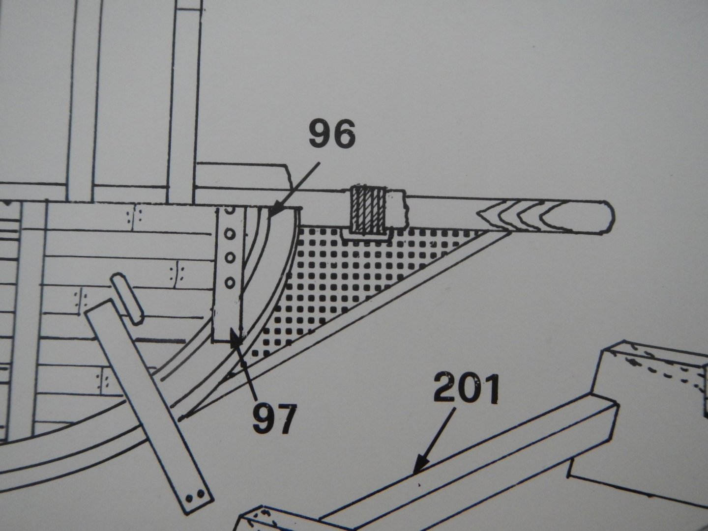
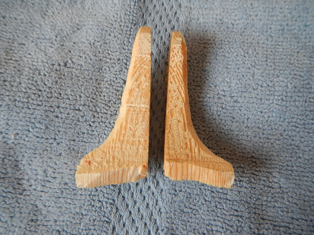
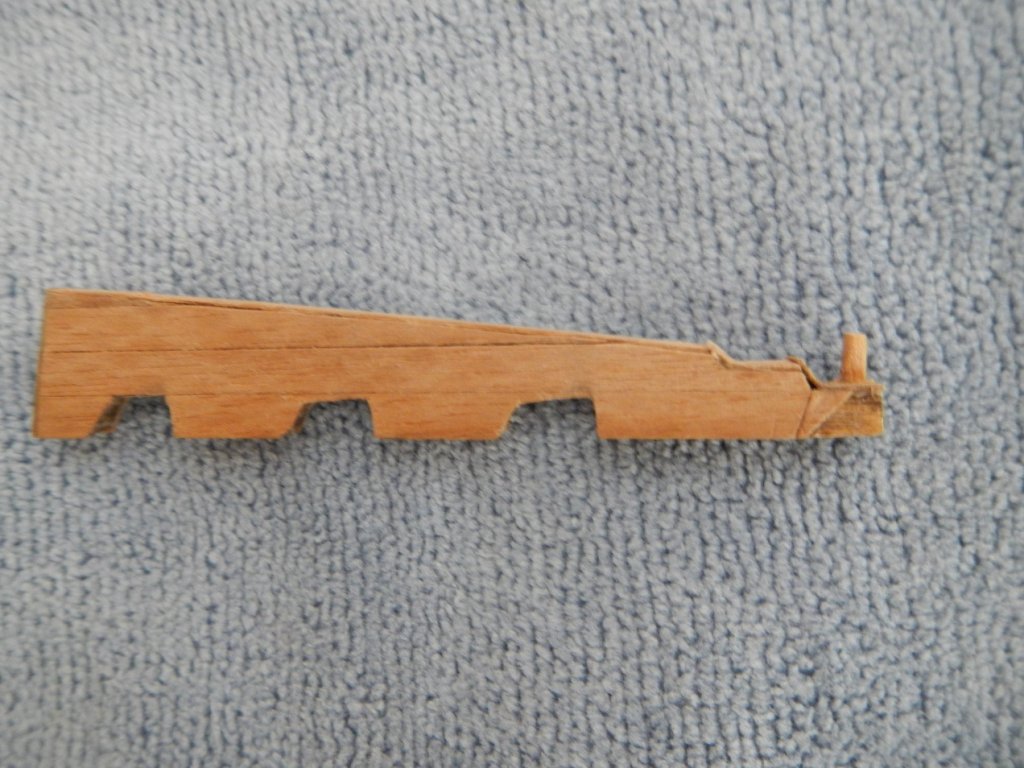
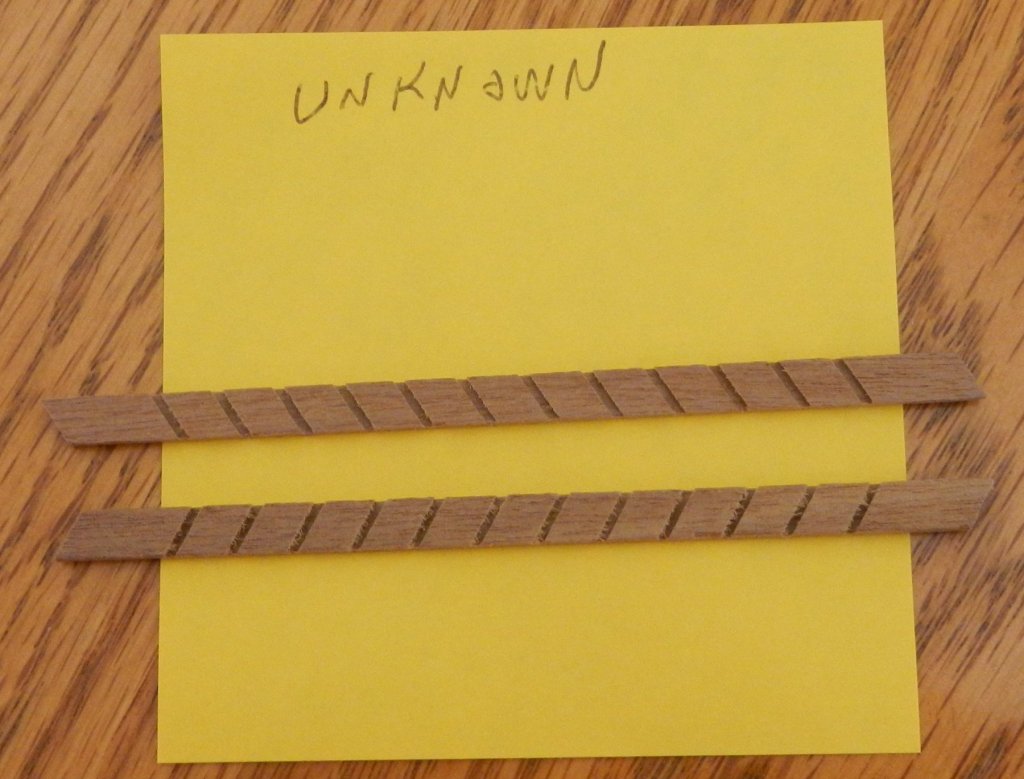
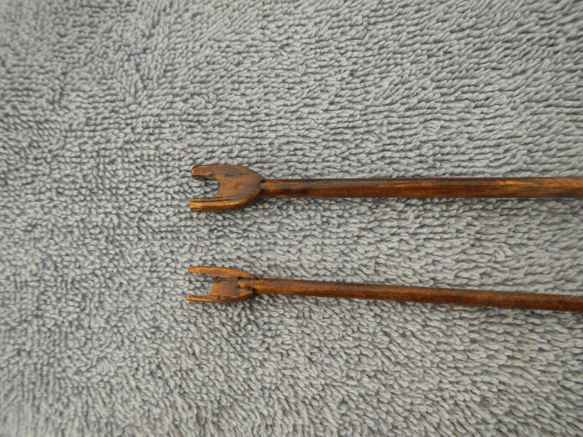
Thanks a lot! I can see that now that you mentioned it, as there are 4 ladders with 3 steps each, and there are 12 slots in these pieces. The kit also had twelve steps, but it looks like the kit needs 24 - 12 for the ladders and six on each side of the ship. I guess I will have to make up the difference!
-
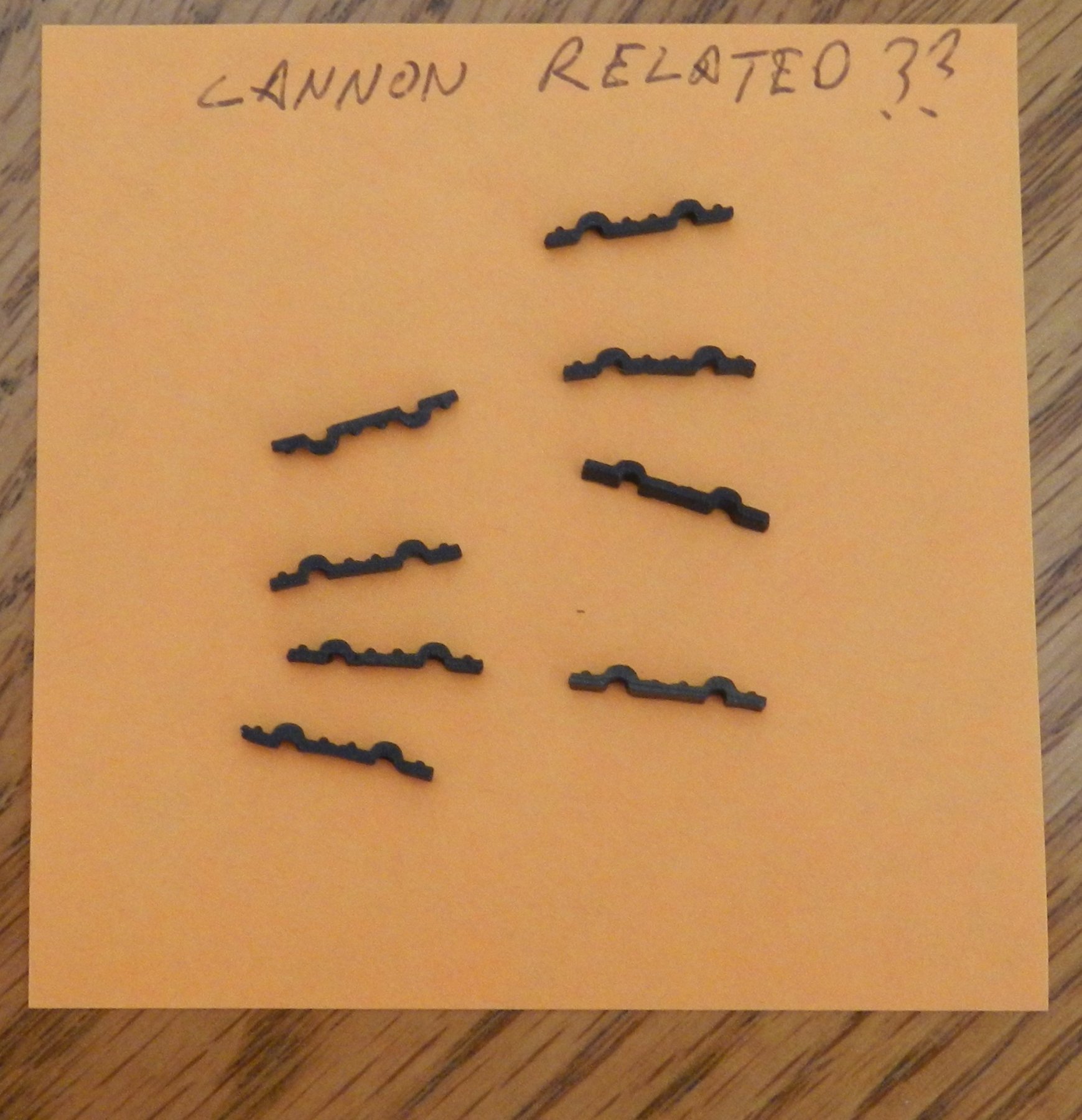
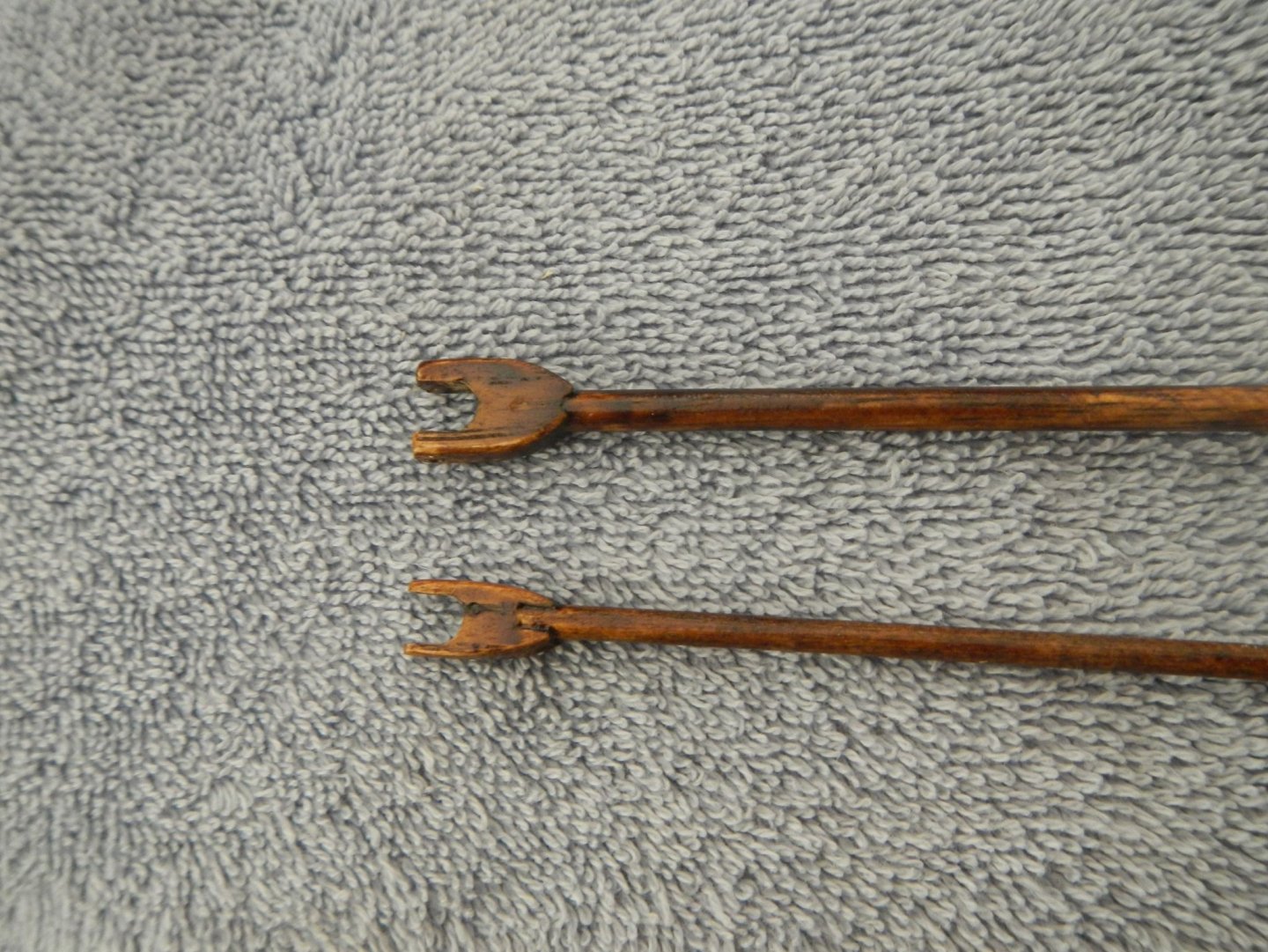
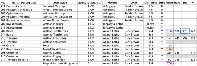
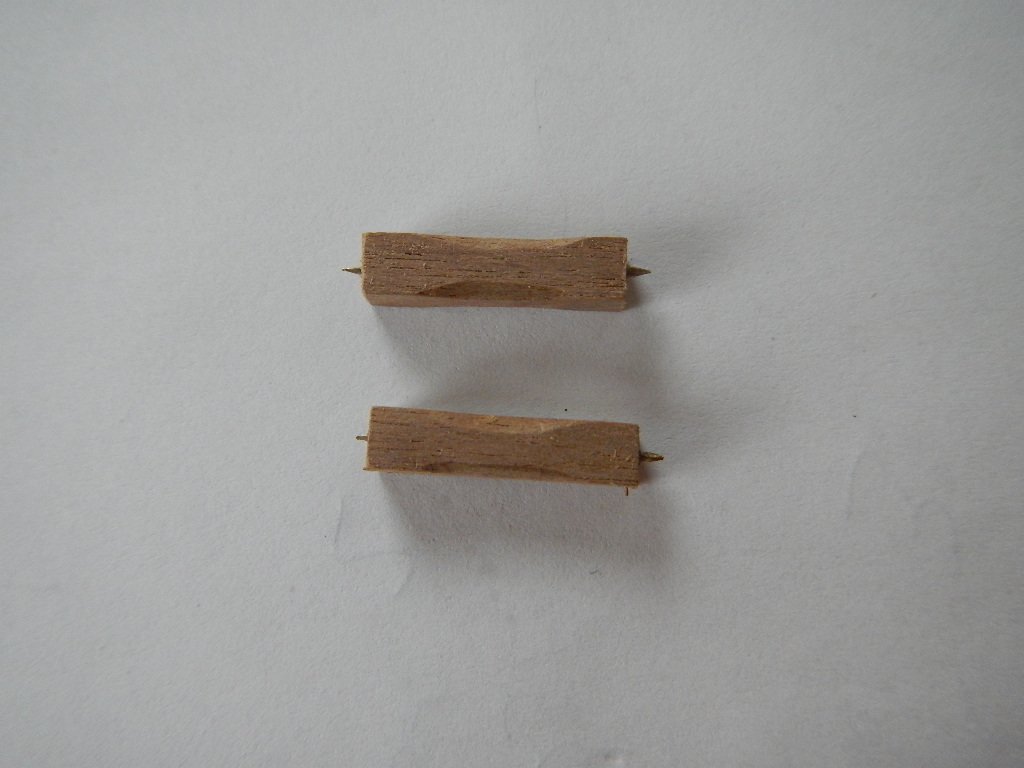
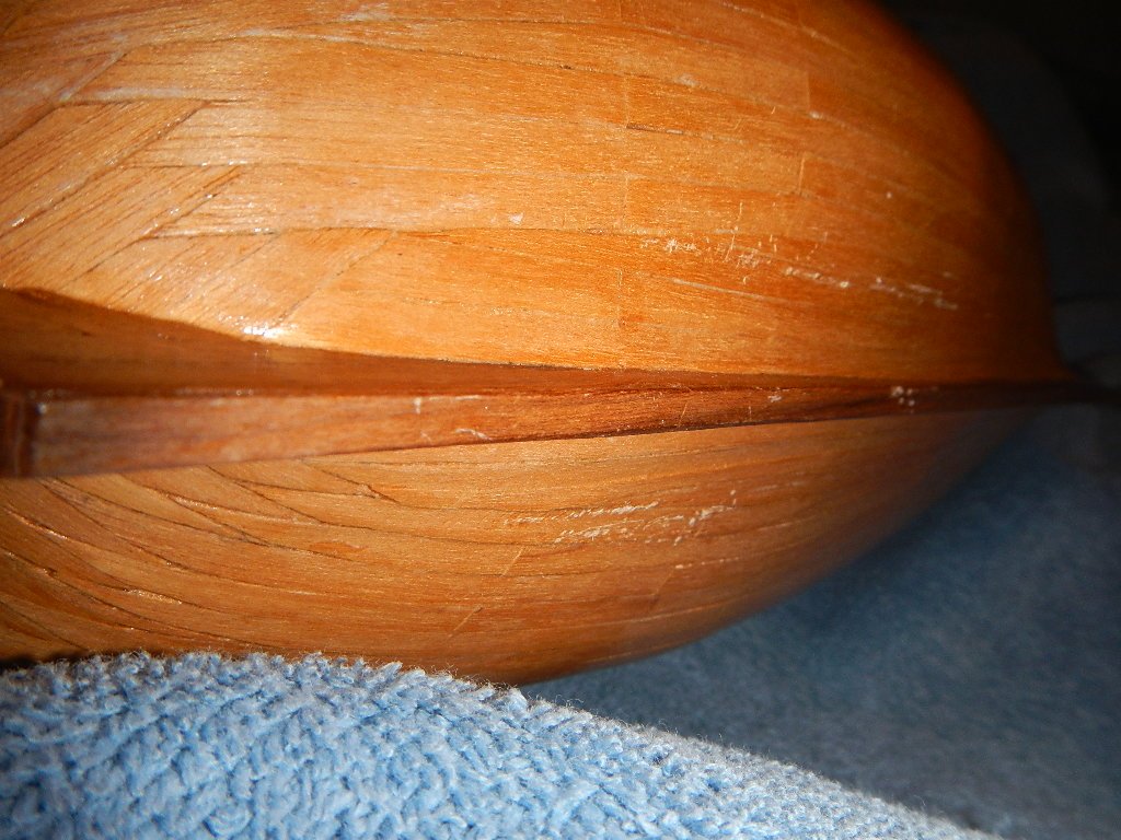
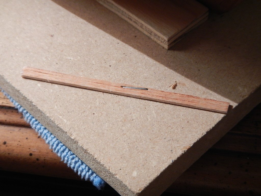
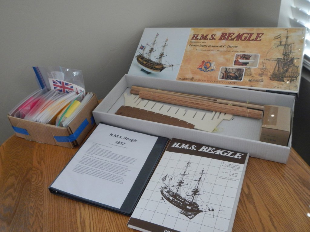
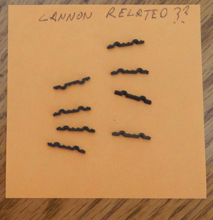
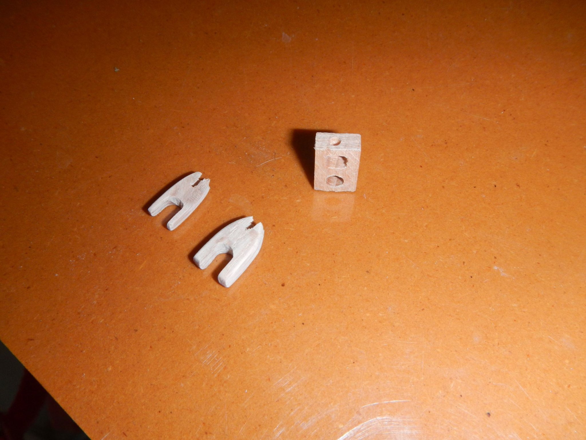
I decided on the H.M.S. Beagle because we had traveled to he Galapagos islands back in 2012. I purchased the kit on eBay after it was no longer available from the manufacturer. This particular kit was originally purchased in 1995, so it us already 23 years old. So far, I have scanned and OCR'd the instructions and parts lists from the original instructions. From that, I created a master parts list to compare to the inventory provided. Almost everything seems to be there, but I have two items that I need some help identifying. These were in the same bag as the cannon and carriages. They look like a strap to hold the wheel axles, but the bumps do not line up with the axle indents on the carriage. And I haven't been able to identify what these might be. Any help identifying these would be greatly appreciated. Thanks!


.JPG.920033aac9638496b9634957520c5f4d.JPG)
.JPG.33fb90c16a5d6e61888d6ad2ffae2a61.JPG)
.JPG.820384c5a37b8dbd9f16c6952a57e5ea.JPG)
.JPG.65bfe705a7d1674c86cc0cc032e71cbd.JPG)
.JPG.8903051cab1fe991cbc888aab2794b2c.JPG)
.JPG.c8a7c1f89d682f67c49dfbecafc5e883.JPG)