KurtH
-
Posts
361 -
Joined
-
Last visited
Content Type
Profiles
Forums
Gallery
Events
Everything posted by KurtH
-
This photo shows 3, as does the Revell model. The planks are just a bit thinner between gun ports. Hope this helps. Actually it really is your choice.

-
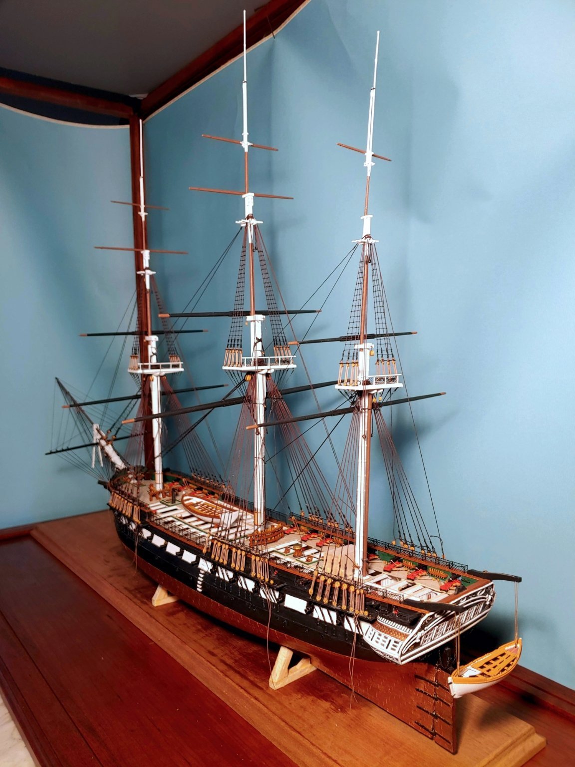
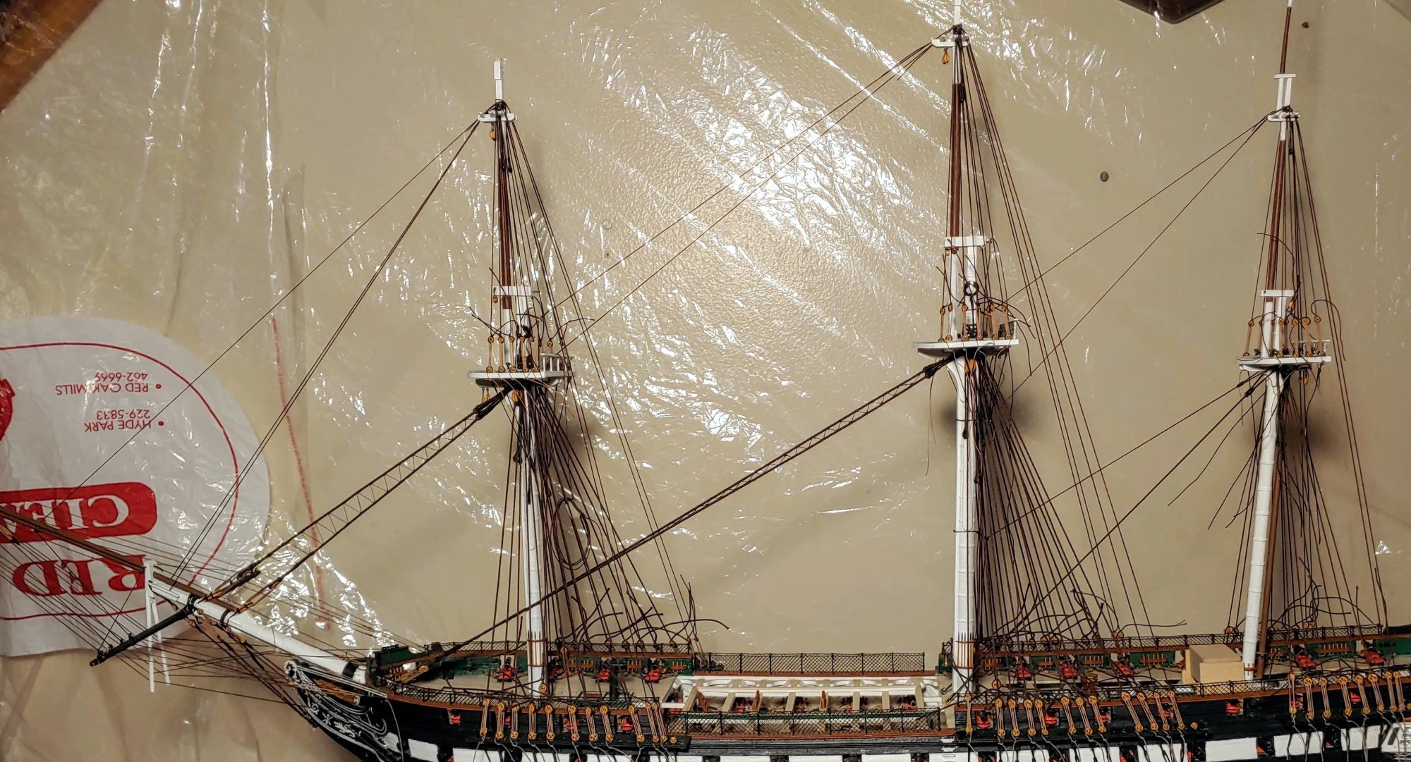
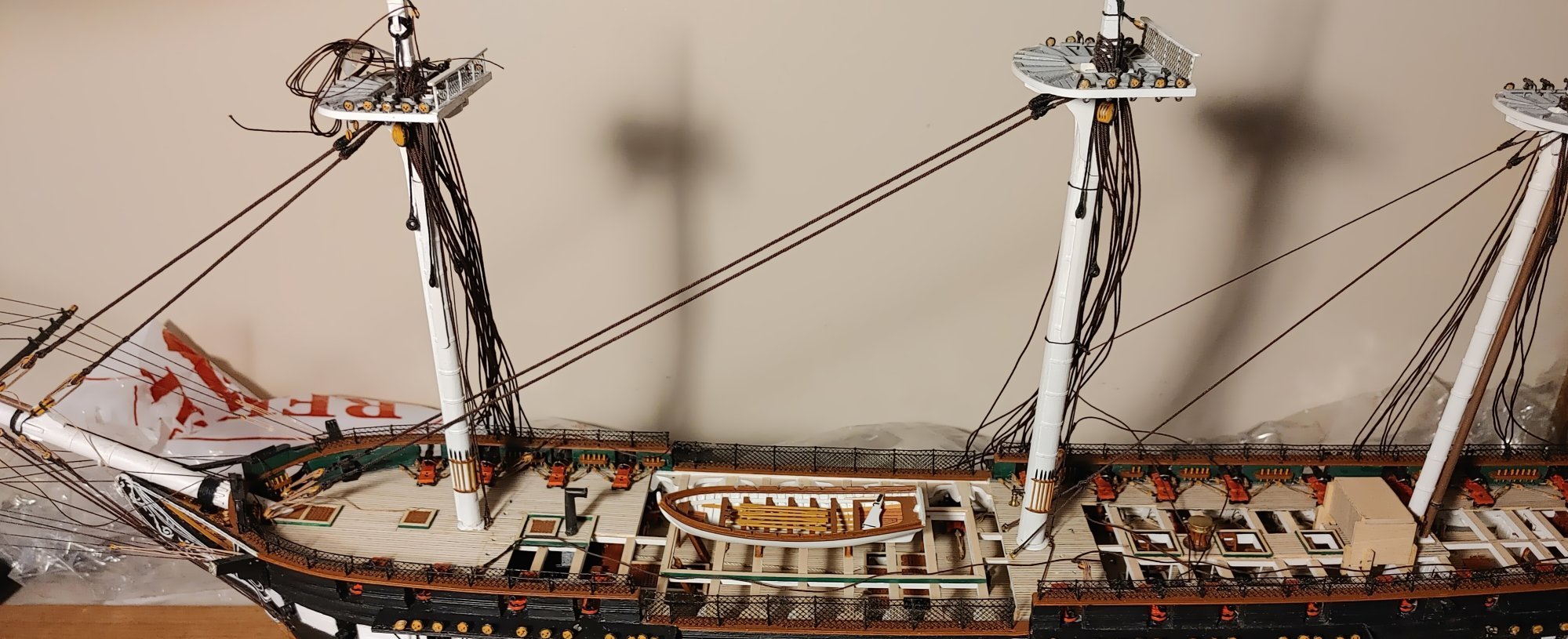
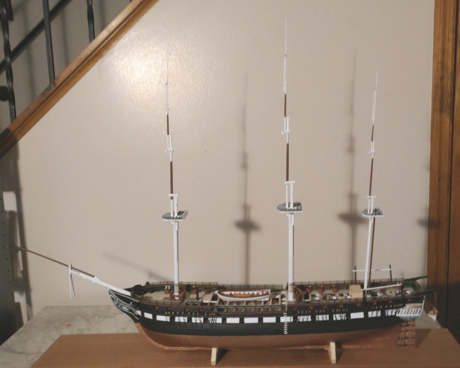
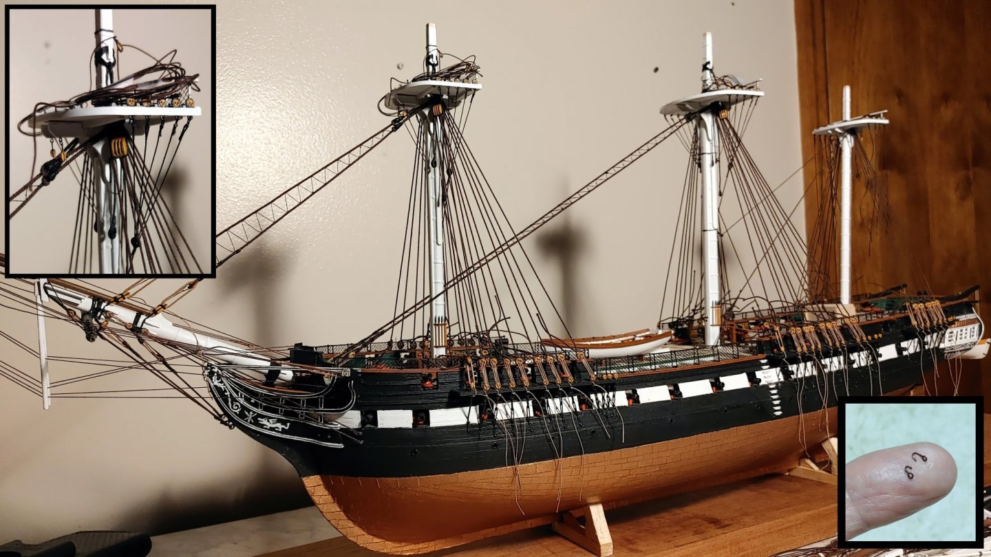
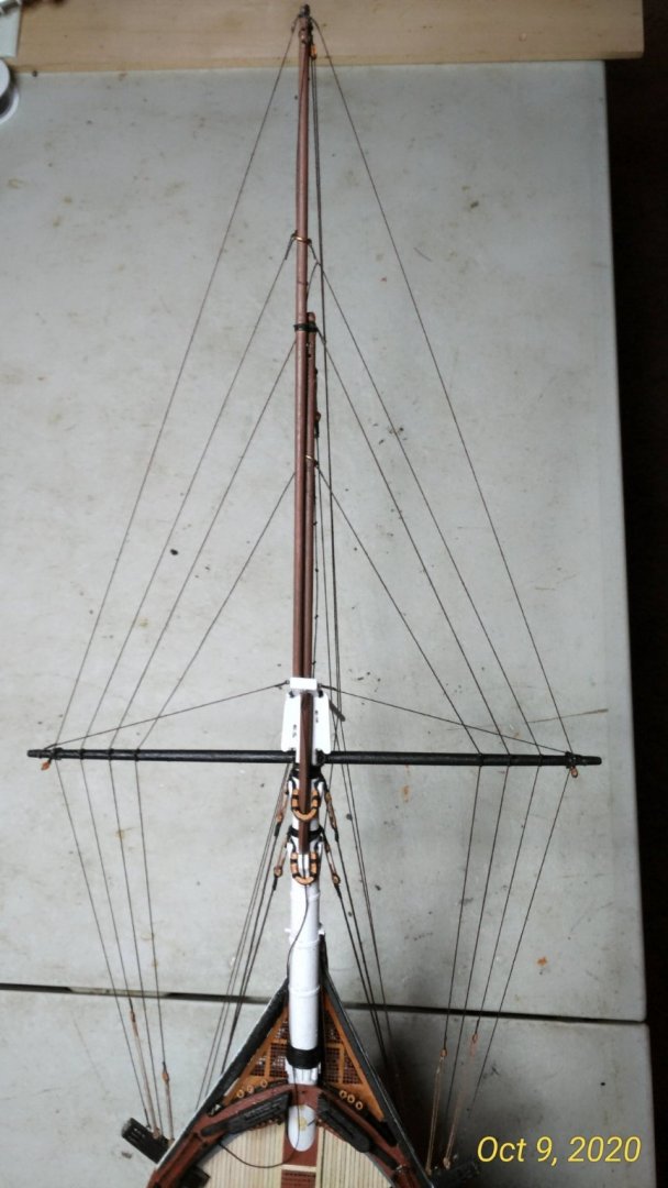
I recently had visitors in, so I temporarily attached the yards to the model. It makes a nice preview of what the model will look like:

- 110 replies
-
- 9
-

-
- Bluejacket Shipcrafters
- Constitution
- (and 2 more)
-
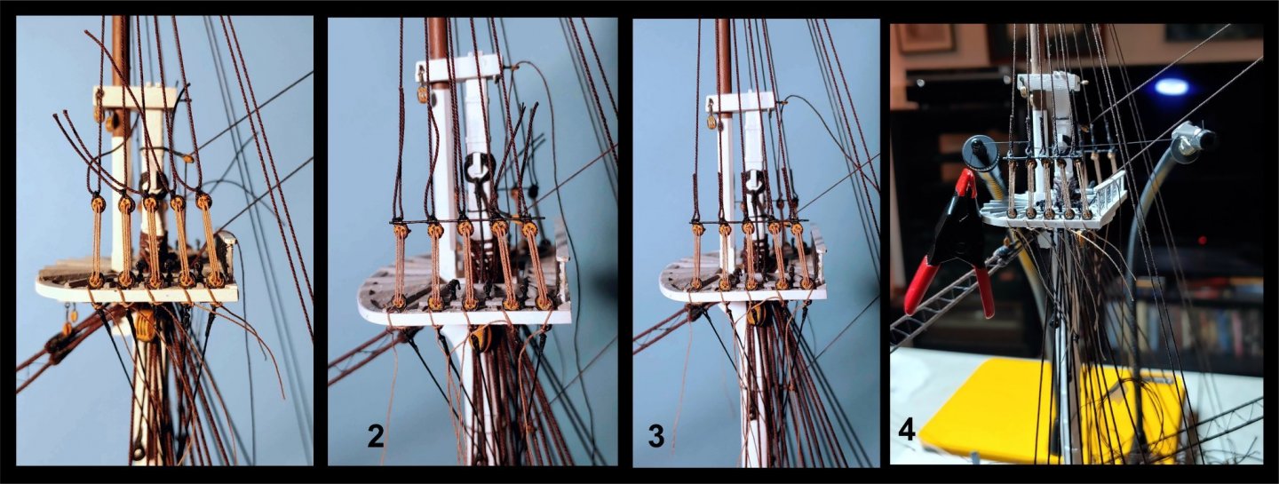
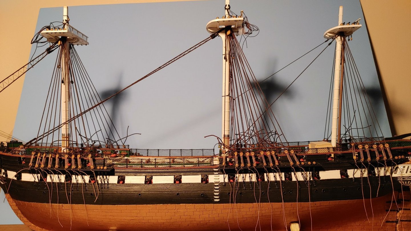
The lower shroud ratlines This is the first new post of this log. In rigging these ratlines, I found that the topmast backstays became a serious obstacle, so I undid the lanyards and cast them off. Here are some shots of the ratlines rigged on the lower and futtock shrouds: Them's a lotta ratlines. As they say, onward and upward. T'gallant shrouds and stays to be rigged next.
- 110 replies
-
- 10
-
-
- Bluejacket Shipcrafters
- Constitution
- (and 2 more)
-
Topmast shroud ratlines I decided to rig the topmast ratlines first. I am not sure that I will do that in the future. I have seen builds in which all the details of the lower mast rigging is completed before the topmasts are even mounted. Apparently, it worked for them. Something to think about in future builds. The ratlines were rigged using BJ's .005 cotton line. It is a bit stiff, which means that the knots must be very tight so that they close properly, and do not show daylight with loops sticking out, but which also means that the ratlines have a stabilizing effect on the shrouds. I used cow hitches on the outer shrouds and clove hitches on the others. The cow hitch does not have an end sticking out sideways, but does not hold very well, requiring glue to secure it. Much has been said about how boring this process is, but I found that tedium was the least of my problems. For me, keeping the ratlines reasonably straight, and the shrouds perfectly straight was an immense challenge. I probably should not detail my ratline rigging technique, as it is unique, time consuming, and most likely not the best way. I did, however, adopt a widely used method for keeping the ratlines properly spaced and the shrouds straight - a cardboard pattern with the ratlines and shrouds drawn, inboard of the shrouds: Here is what I ended up with: This brings me to where I was when I deleted my entire log. I would like to thank those who encouraged me with their "likes", and especially Mort Stoll for his constant support throughout the process.
- 110 replies
-
- 7
-
-
- Bluejacket Shipcrafters
- Constitution
- (and 2 more)
-
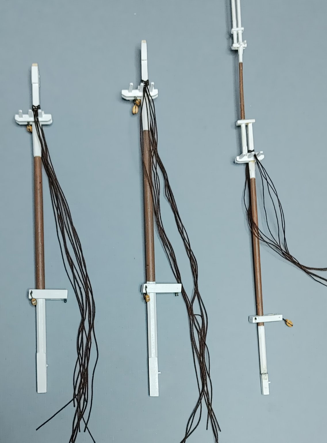
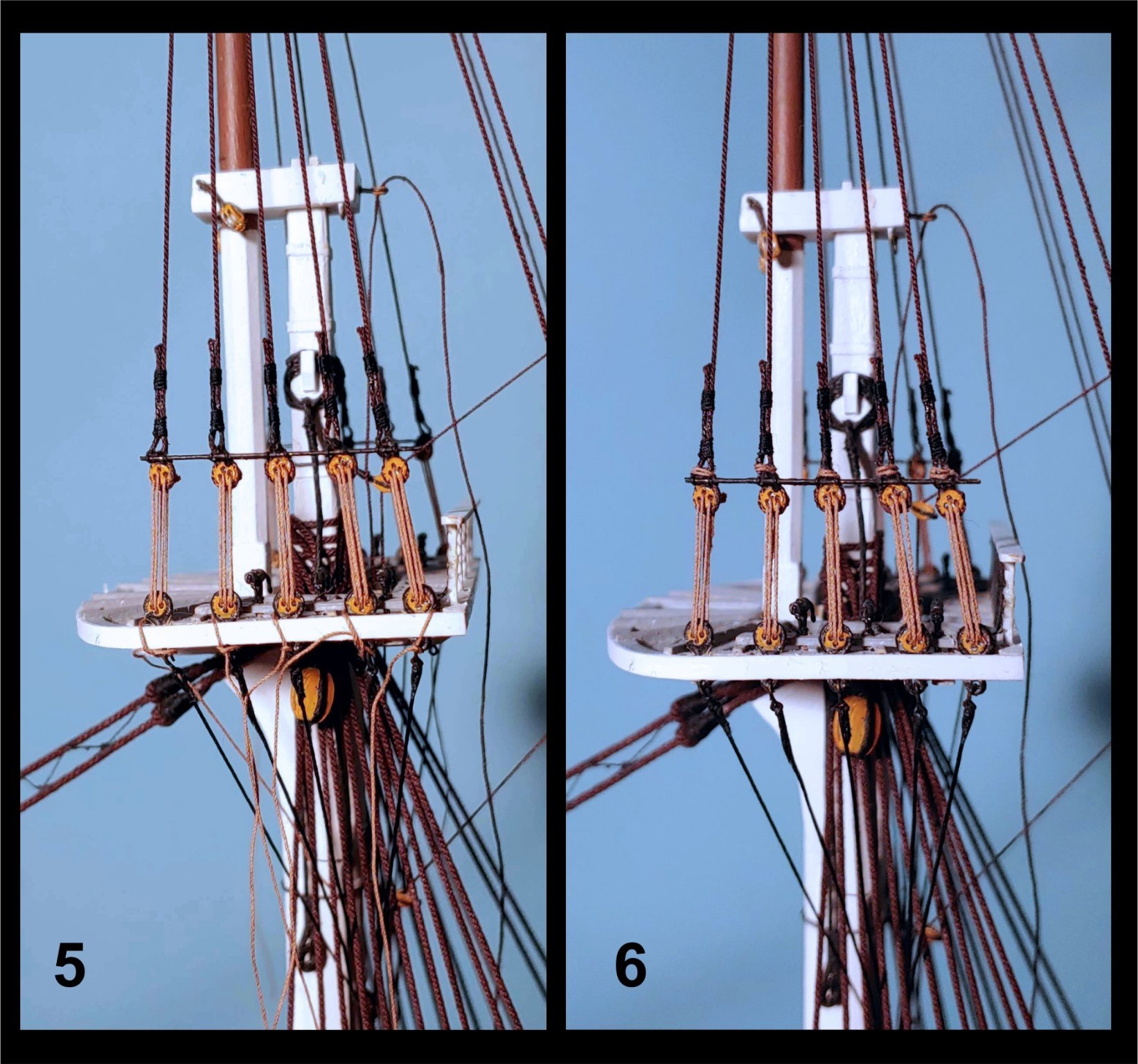
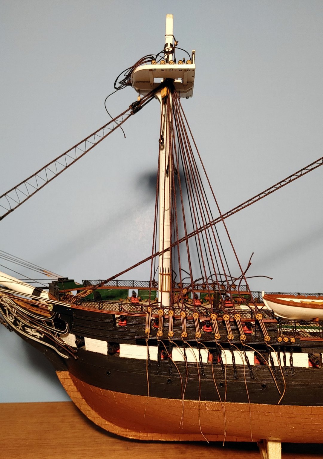
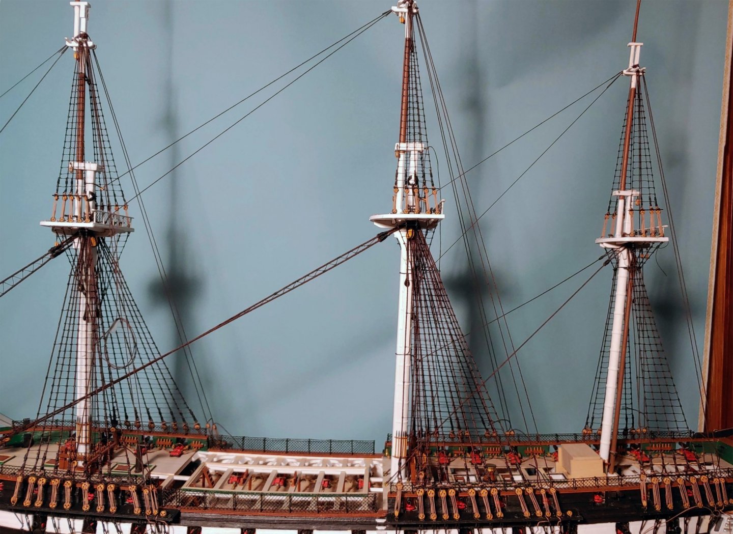
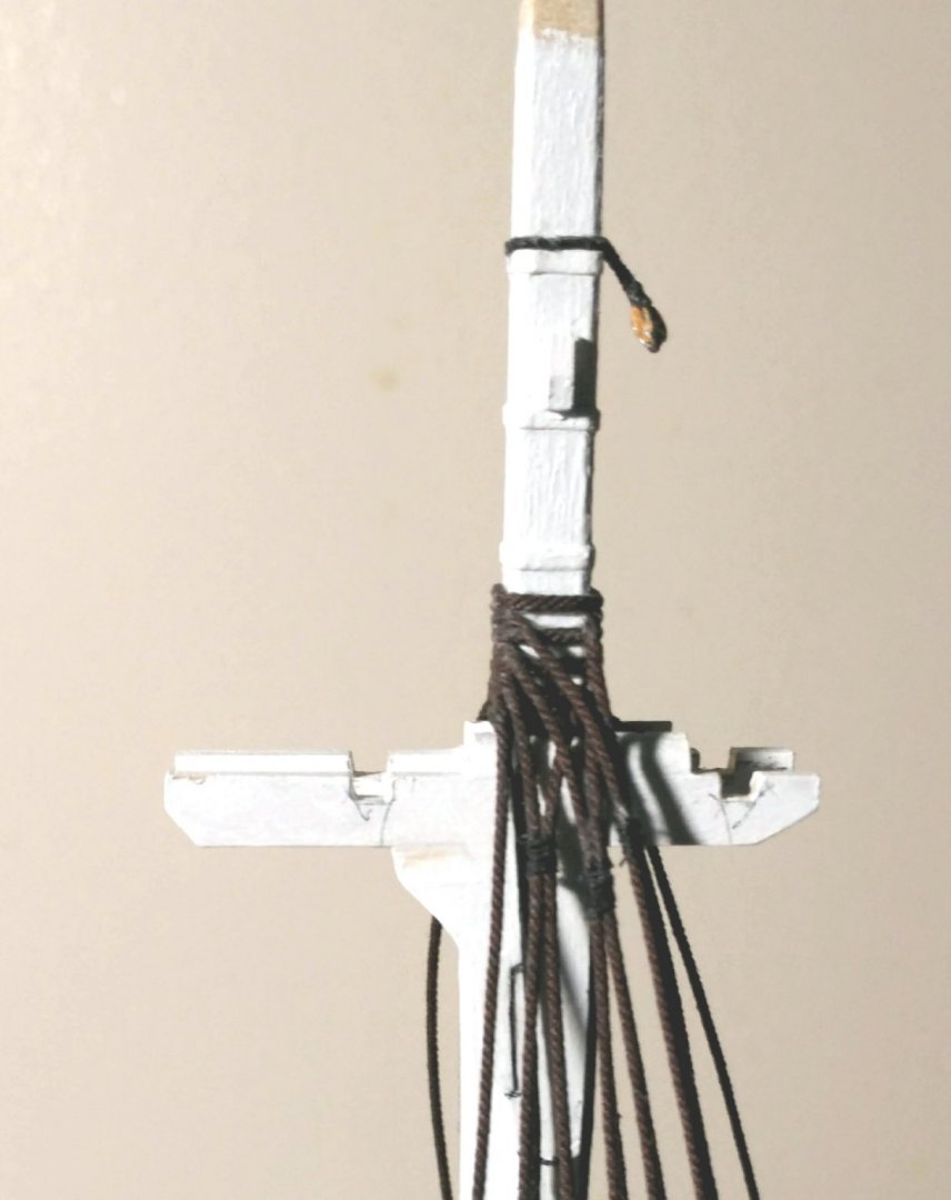
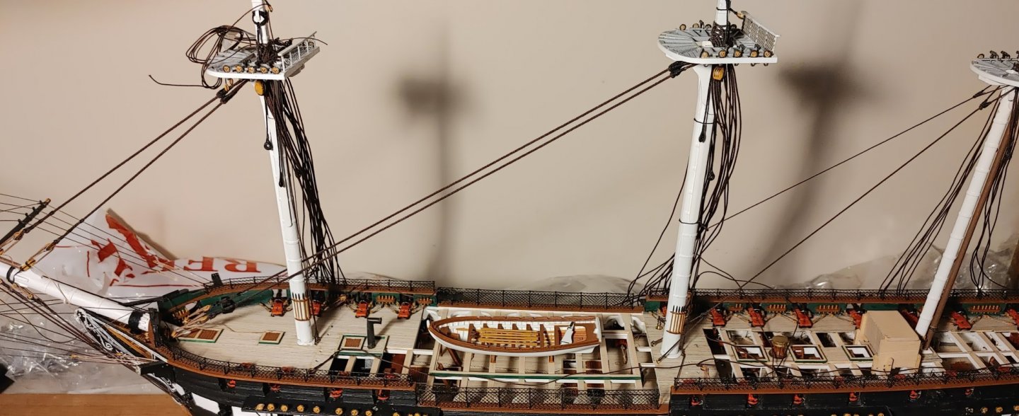
The topmast shrouds and backstays The topmast heads, like the mast heads, were rigged off model, using the same procedure as before: The blocks installed under the crosstrees are for jeers. The blocks installed on either side of the mast caps are for lifts. The block installed on the aft end of the mizzen mast cap is for the spanker gaff lifts and halyards, Eyes installed on the under side of the for and main mast caps will have the truss tackles hooked into them. Here is a shot of the topmast shrouds, fore and aft stays, and backstays in place: The following composites show the method used for completing the rigging of the topmast shrouds: 1. Shrouds glued to the deadeyes, the shroud crossing outboard over itself, and the short end on the left side as described in Ben Lankford's book "How to Build First-Rate Ship Models from Kits" published by Model Shipways - Model Expo. Throat seizings done. 2. Sheer poles installed with their lashings, allowing alignment of the deadeyes. 3. Remaining seizings done. 4. Method of doing the seizings using a clamp and the Quad Hands. 5. Closeup of the seizings and sheer pole. Sheer poles lashings just visible. 6. Thinking that the shrouds were stable, having flexed the mast in every direction without affecting them, I secured the lashings. Months later, when the weather is colder and dryer, they have gone slack. Hopefully, I can undo the lanyards using de-bonder and tighten them. Here is a shot of the main shrouds finalized in the same manner as above:


- 110 replies
-
- 6
-
-
- Bluejacket Shipcrafters
- Constitution
- (and 2 more)
-
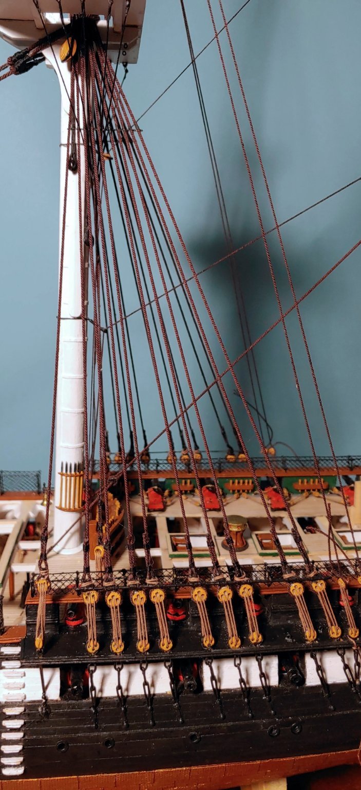
Futtock and bentink shrouds Here is a shot of the bullseye-lanyard rig for the bentink shrouds: The following composite shows a closeup of the futtock shrouds, the hooks used to attach them to the top deadeye strops, and a view of the model with these all in place:
- 110 replies
-
- 6
-
-
- Bluejacket Shipcrafters
- Constitution
- (and 2 more)
-
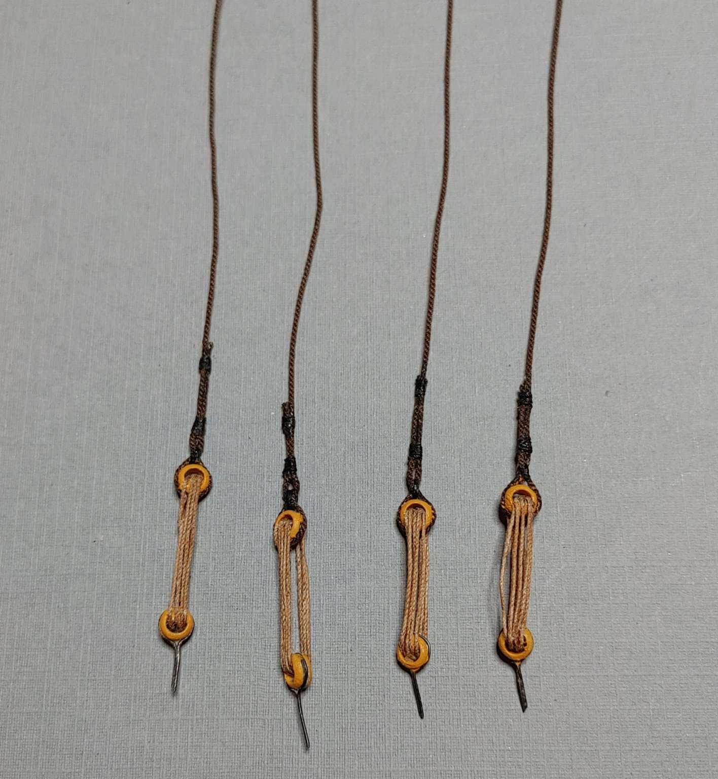
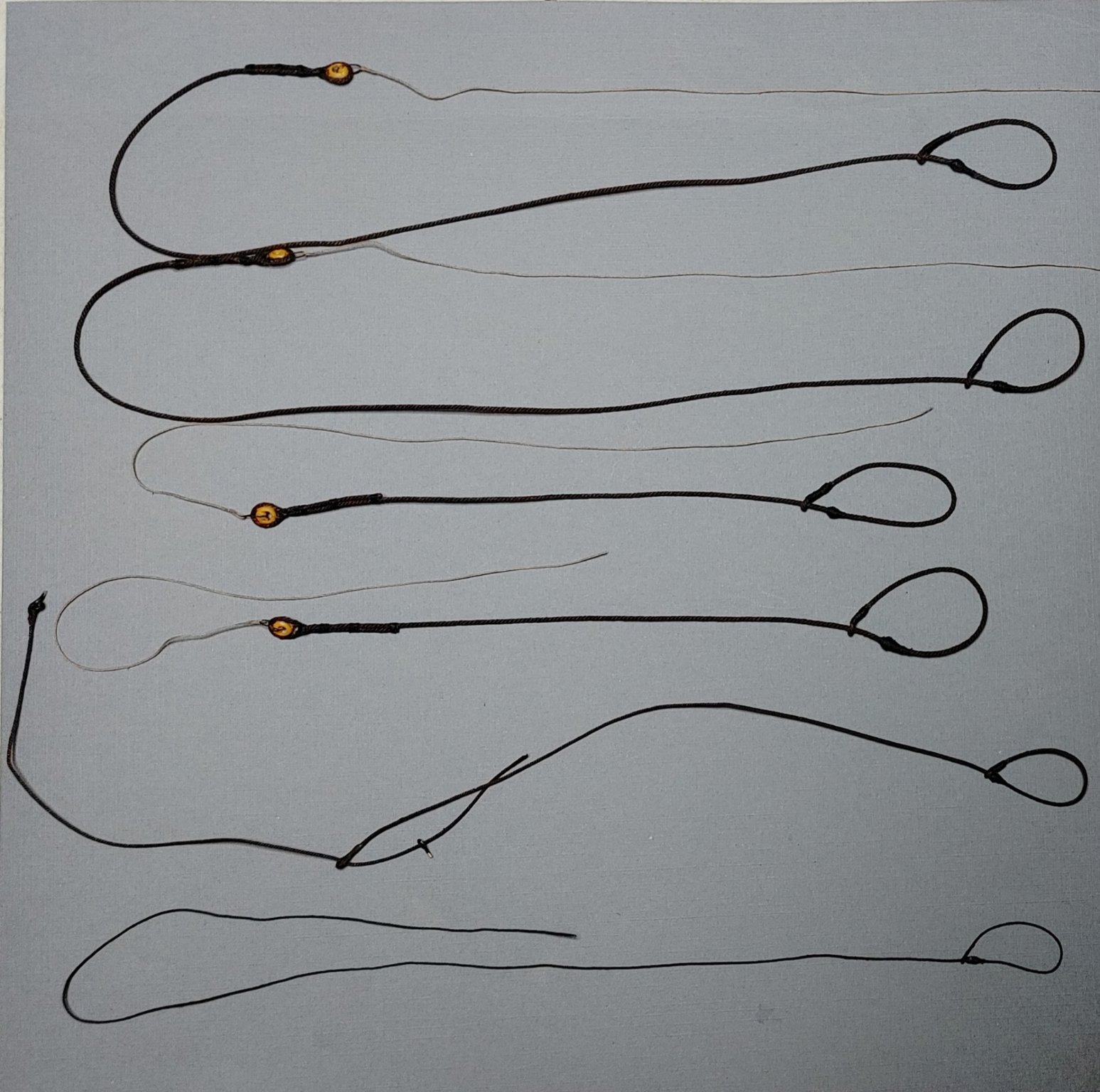
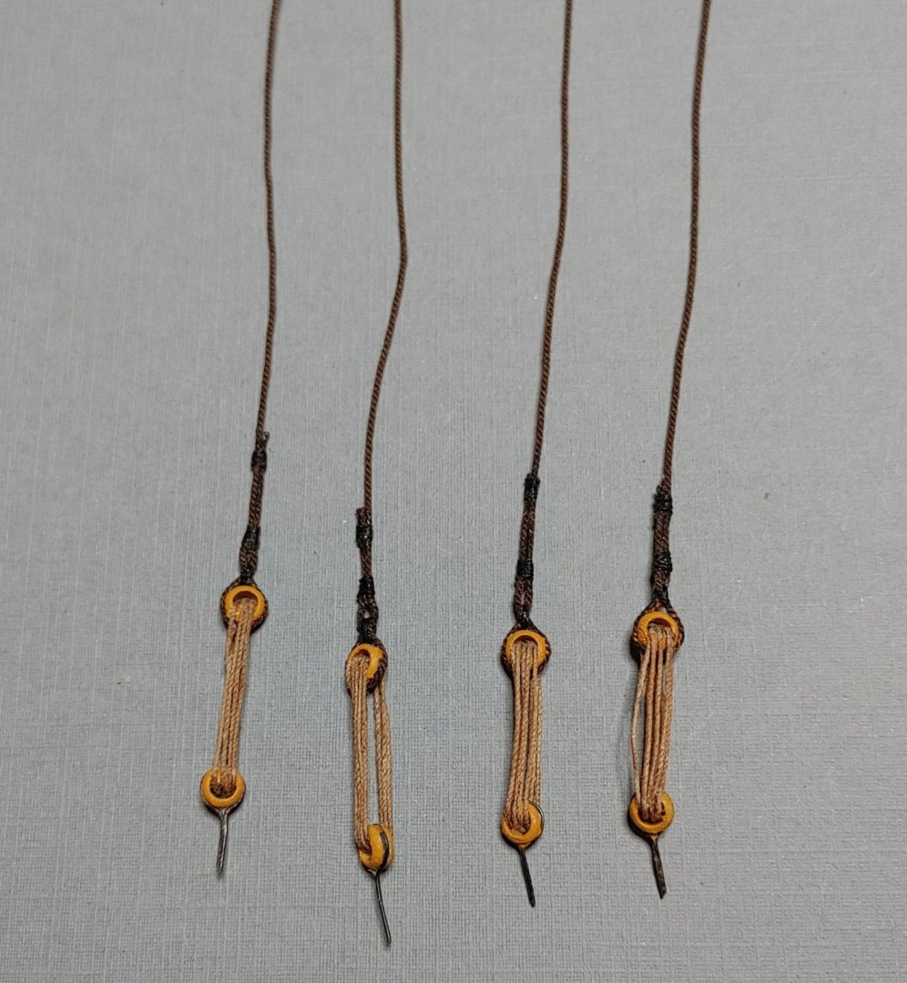
Rigging the masts It makes sense to rig the mast heads off the model. First up were the Burton pendants. These were made from BJ rope and BJ metal bullseyes with their centers reamed out to make them look like thimbles as much as possible. I also installed blocks for topmast stays. Next came the shroud pairs beginning, as prescribed, with the forward starboard pair. Next up, the jeer pendants. The preparation of the lower mast stays involved making a mouse, which I did by winding .005 line around the stay until I had something that looked like a mouse, the loop which is essentially a fake eye splice, and the bullseye with its lanyard. Here the masts are glued in and the stays attached to their respective bullseyes. Ends are left long to allow for future tensioning: A closeup of the fore and mainstay bullseyes, open hearts and lanyards: The mizzen stay rig at the deck: Before attaching the shrouds to their deadeyes, I thought I should get the snaking done. Here is the method I used which is essentially the same as Xken's, with a few departures: 1. The design drawn out on a piece of foamcore. Outer lines represent the stays, the zig-zag line represents the snaking. 2. Masking tape cut to shape and laid down sticky side up, leaving the turns in the zig-zag which will be attached to the stays exposed. 3. T pins passed through metal bullseyes, then inserted into the foamcore at the turning points. Line (BJ .005") having been stretched and stiffened with diluted PVA threaded around the pins resting on the bullseyes which hold it off the ground so that additional stiffening using liquid CA may be applied without gluing it permanently to the tape. Gotta be careful not to allow any beading of the CA to occur on the line. 4. When set, the T pins are removed, the bullseyes are removed, then the T pins are reinserted. The line is then pressed down onto the sticky tape. 5. An additional identically shaped piece of masking tape laid over the line sticky side down and pressed against the lower tape capturing the line in between and stabilizing it ready for installation between the stays. This is tricky. if the adhesive on both pieces of tape is strong enough, removal of the tape in step in step 7 may be impossible. I laid the upper piece of tape down on a surface and peeled it back off a few times to reduce the strength of the adhesive. 6. Install the assembly between the stays. Most modelers like to tie the snaking to the stay. At this scale, I saw no way to do that neatly, so I used Elmer's CA. 7. Carefully and slowly peel off the tapes and voila. Actually I did the mainstay first, but decided to base my post on the forestay which came out better, Practice makes perfect: Shrouds attached, lanyards rove. Ends left long. I was flying blind as to when to finalize these lines, so I kept my options open as much as I could. Shrouds are glued to the upper deadeyes but not seized: Looking at the netting rails at the waist, the counter clockwise twist of the hull becomes evident. I chock the fact that I did not catch that at the beginning up to inexperience.


- 110 replies
-
- 5
-
-
- Bluejacket Shipcrafters
- Constitution
- (and 2 more)
-
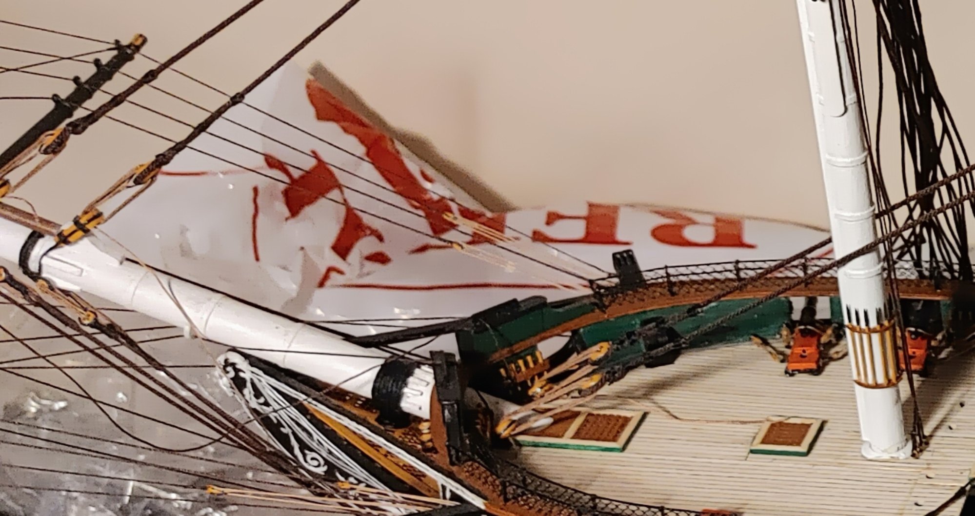
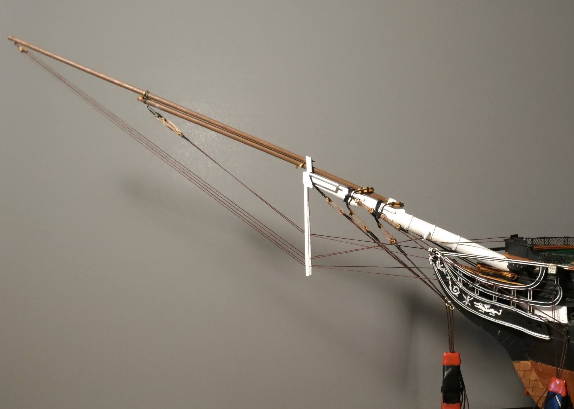
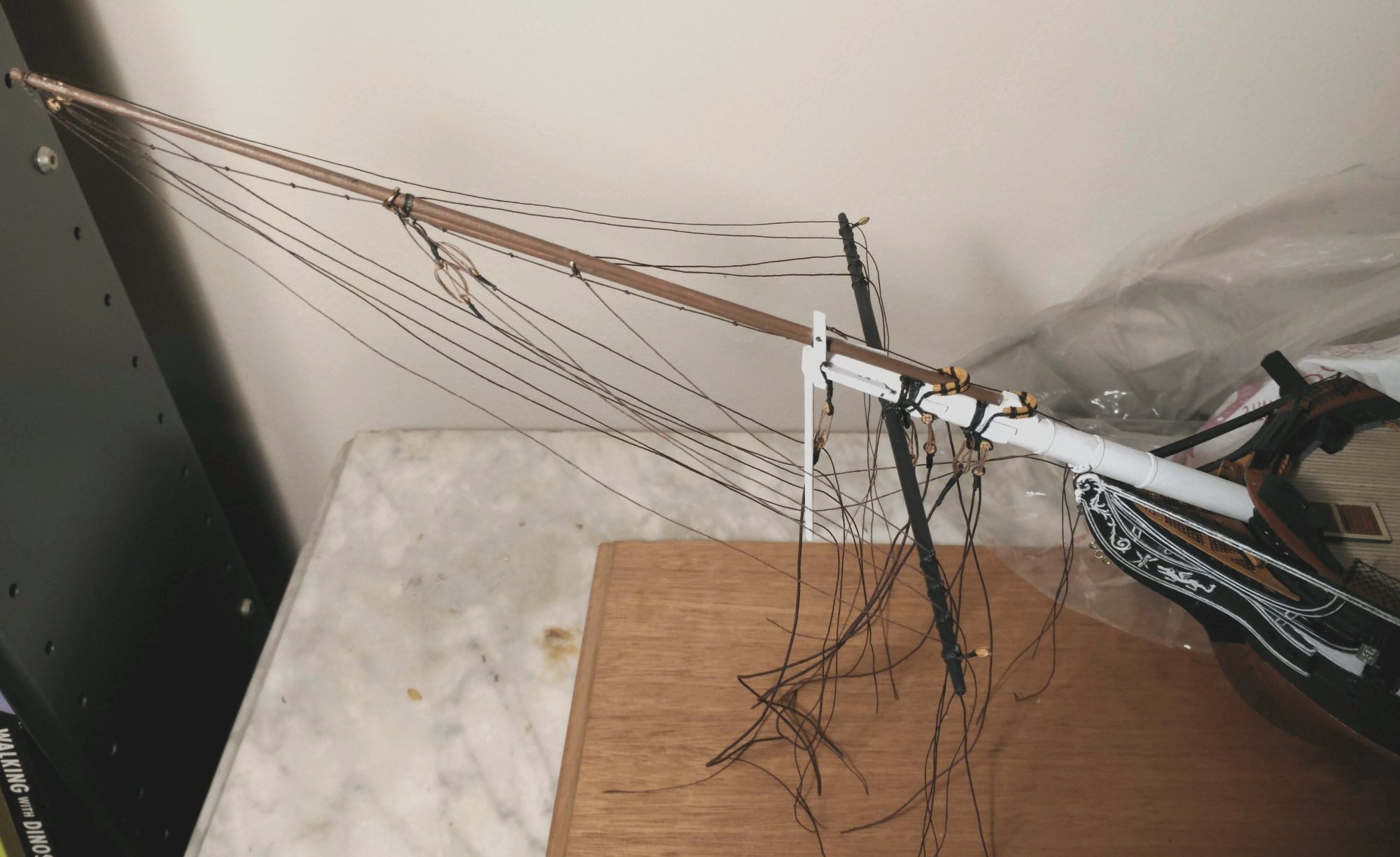
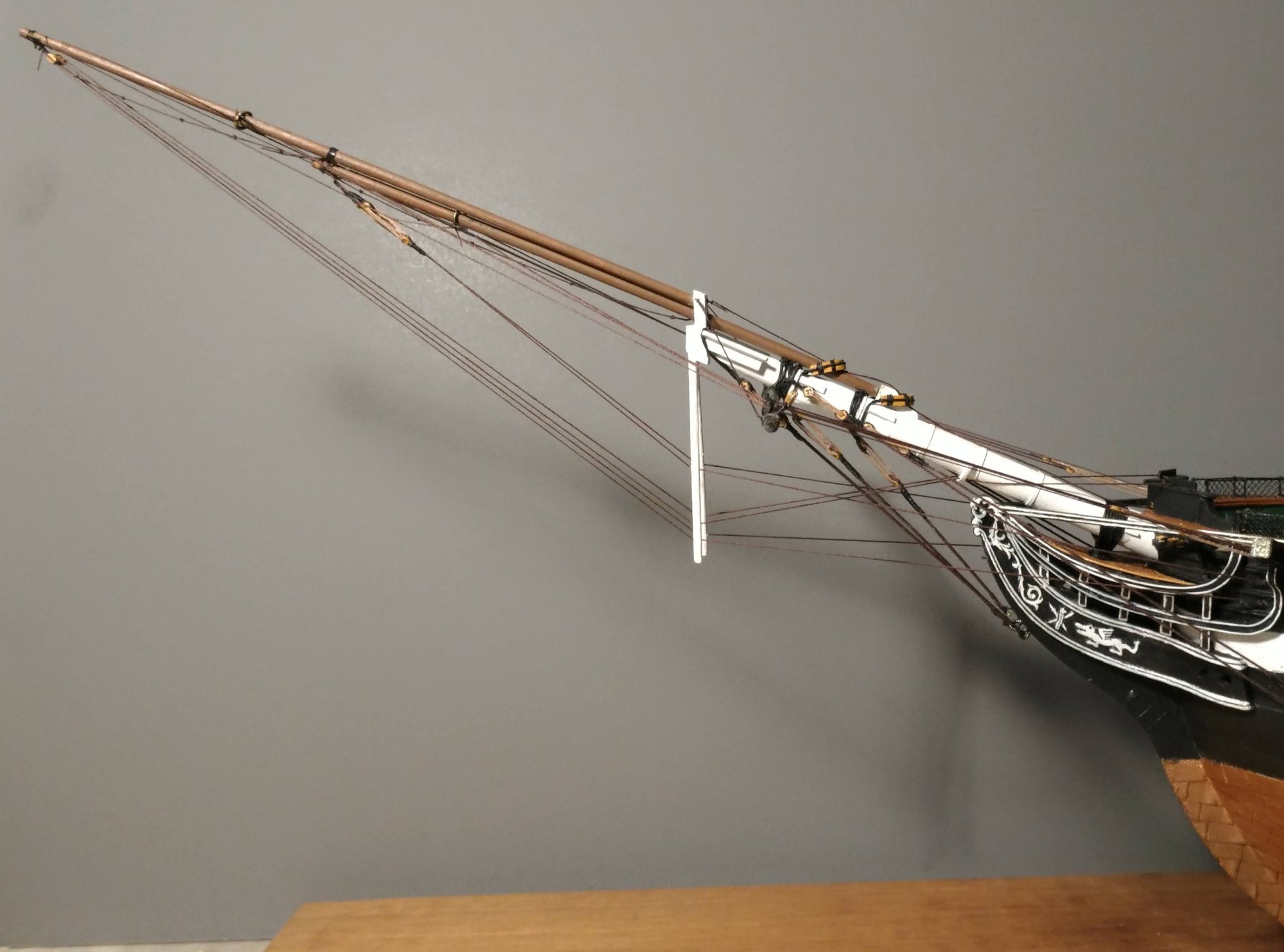
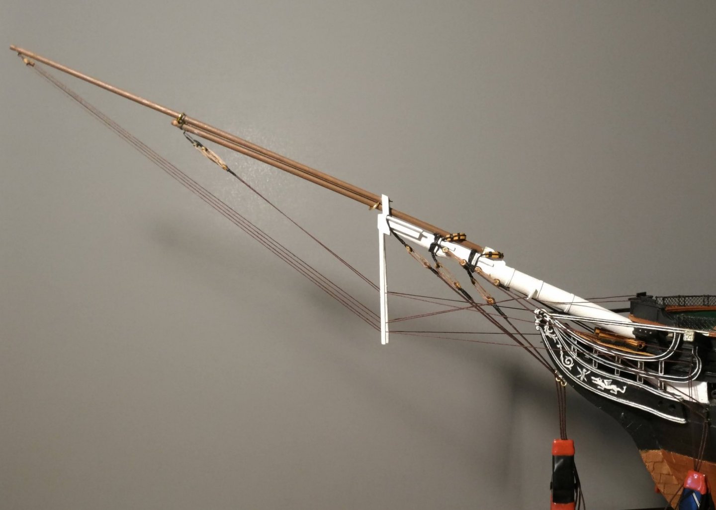
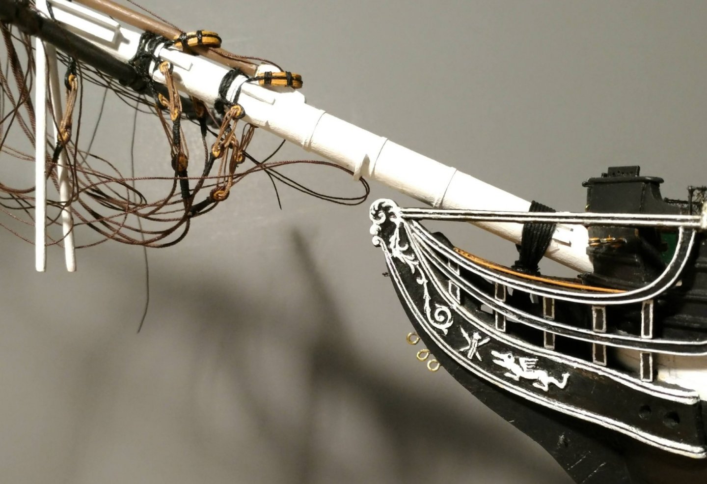
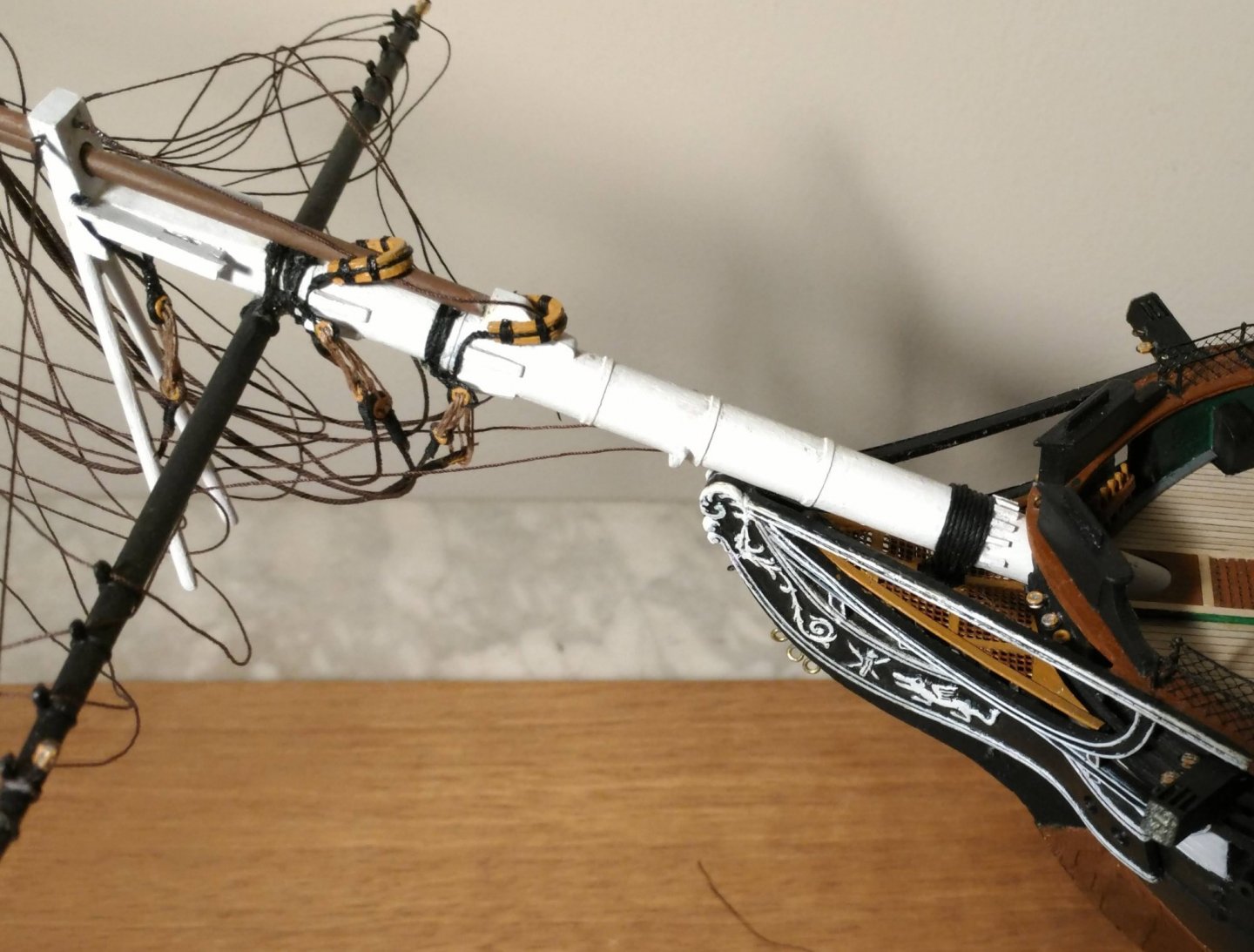
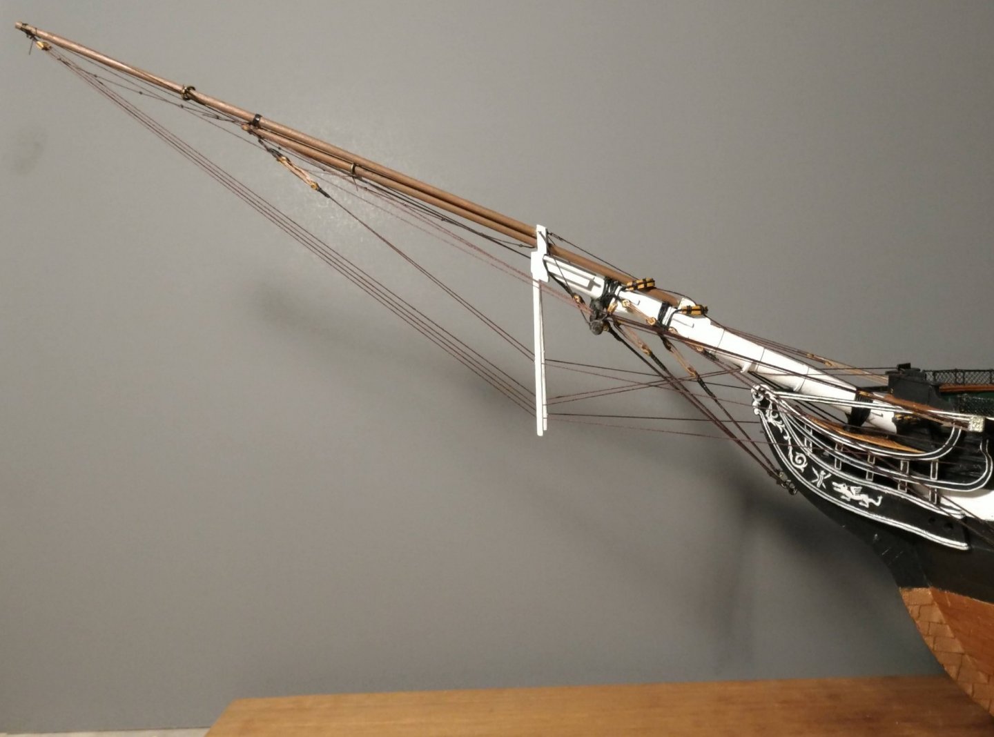
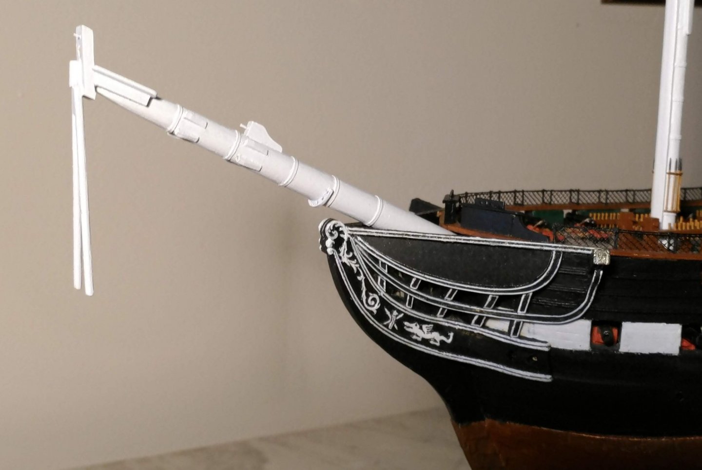
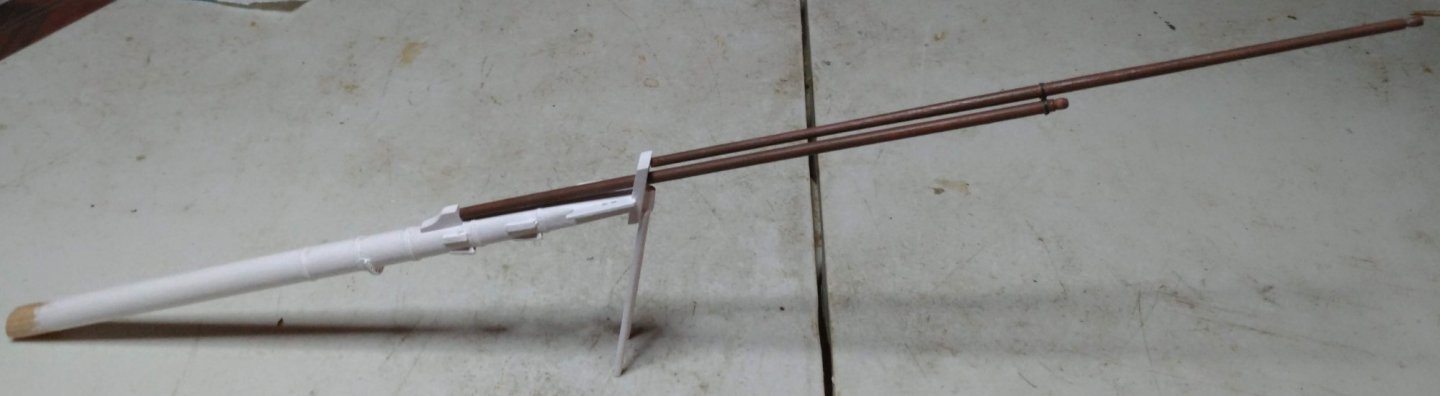
Rigging the bowsprit This rigging looks more like the present ship, and is less complex than that described in the plans. I installed the open hearts for the forestay, and set up the bullseyes/lanyards, and deadeyes/lanyards for the bobstays, jib boom martingale guys, and bowsprit shrouds, then temporarily rove them through eyebolts installed on the hull and held them taut with suspended clamps to see how they would look: Casting all these lines off once more, I then crossed the sprits'l yard and rove the jib boom guys through the sprits'l yard fairleads: Bullseyes and blocks for the upper stays stropped and painted (left), then installed on the hull (right). Unlike the plans, these are oriented horizontally, so as to leave room for the seats of ease to be reinstalled when the time comes. Blocks installed on the catheads for jib boom guys: Gammoning and gammoning cleats installed: Another view of the gammoning: Rigging attached. Glued but not seized, so that if I need to retension them, I can use de-bonder to free them: Two more views:

- 110 replies
-
- 5
-
-
- Bluejacket Shipcrafters
- Constitution
- (and 2 more)
-
Rigging the model I did rig the plastic models I built as a teen, but it consisted mainly of just tying one end of a line to point A, and the other end to point B, which does not really count as experience. For all intents and purposes, I am a neophyte at this. The posts that follow are intended merely to document my progress. For a real "how to" series of posts, I recommend Xken's MS Constitution build log. It is very methodical, detailed, and thorough. I did not attempt any serving, parceling, puddening, or worming in this build. The kit includes a wide variety of ropes of every size you would need. It comes in two colors, black and white. I did not like the white because it does not look like rope, and I was disinclined to dye it all. For the rigging of the masts and spars, I am using Syren dark brown, light tan, and dark tan rope which is as good as it gets and looks just like rope. For seizings, I am using BJ .005 black line. The appearance of the larger sizes of BJ.s black rope is smooth and shiny which to me has a "served" look. I am using this for things like pendants, trusses, etc. I use BJ's black annealed steel wire for stropping blocks. It looks neat, and is easy to form into hooks when desired. I use PVA glue when securing ropes to wood, but I use Elmer's CA when stropping the metal blocks as I described above in my discussion of the carronade rigging. I could not get diluted PVA to hold seizings, so I use CA for that too, applying it to the underside of of horizontal seizings and the inboard side of vertical seizings to minimize visibility of shiny spots. I also apply black paint with a fine brush as needed. Many modelers will be aghast at this, but I have also heard from some other experienced modelers who have been using CA for rigging for years and have had no problem. Time will tell.
- 110 replies
-
- 3
-
-
- Bluejacket Shipcrafters
- Constitution
- (and 2 more)
-
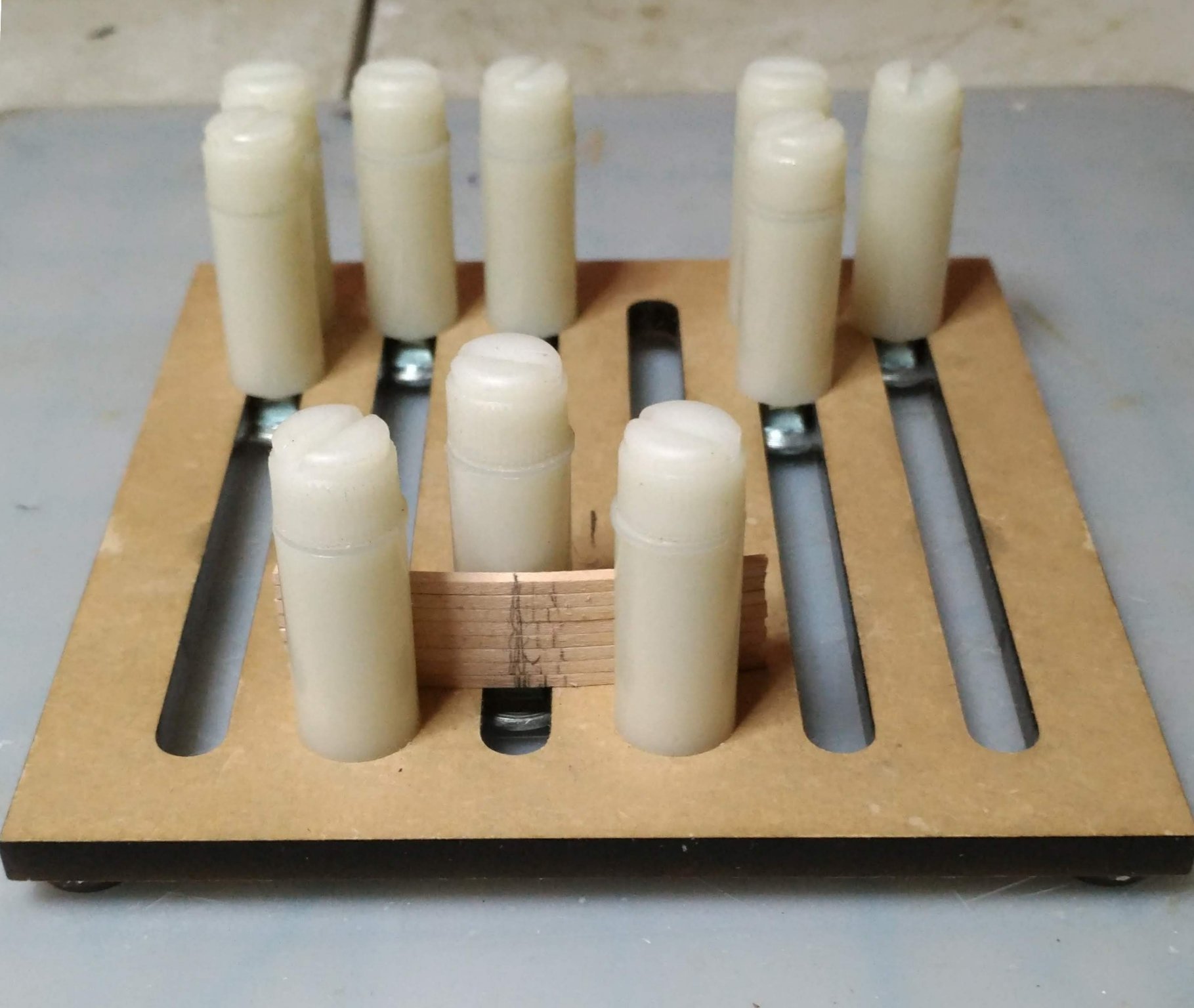
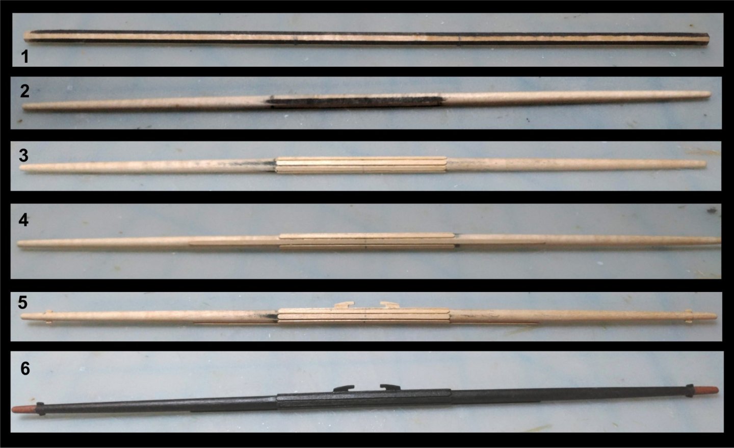
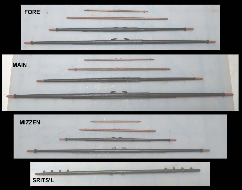
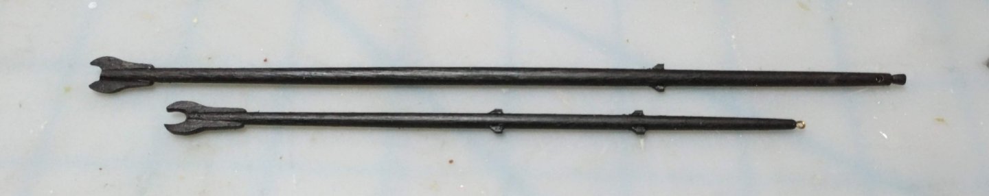
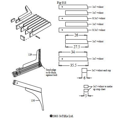
The spars As I did with the topmasts, I elected to make the course and topsail yards from square stock. I painted the square stock black so that I could keep track of which facets were the result of imperfect planing, and which were from more perfect milling at the factory. The latter would then bear the sling cleats, the back fishes, and the top and bottom chafing battens, and the former would bear only the diagonal chafing battens. Perhaps someday, I will be able to make all facets equally true. Battens and stop cleats were made from 1/32" basswood while the sling cleats were built up in much the same way as the jeer cleats were on the lower mast heads. Tapering was done by hand, as the double ended taper precluded using a drill. Rolling the yard across the table under my fingers confirmed symmetry. The t'gallant and royal yards were made from dowel, as there are no octagonal sections on these. 1/64" plywood was used to make the stop cleats on these. I may yet install bits of brass rod into the ends of the lower yards to which to seize the flemish horses. The Sprits'l fairleads are metal bullseyes with the centers reamed out and stropped with annealed steel wire (34 gauge, .010" BJ #902) which was inserted into holes in the yard. Wire was then glued around the yard to make it look like it was all one piece. Since this was done, the mizzen t'gallant yard up and disappeared on me, so I will have to make another. Fittings to be attached when all standing rigging is done, and before running rigging begins. Spanker gaff and boom: I made up the foretack boomkins which will be installed when all other lines at the bow have been rigged. This concludes the wood work for the model.
- 110 replies
-
- 4
-
-
- Bluejacket Shipcrafters
- Constitution
- (and 2 more)
-
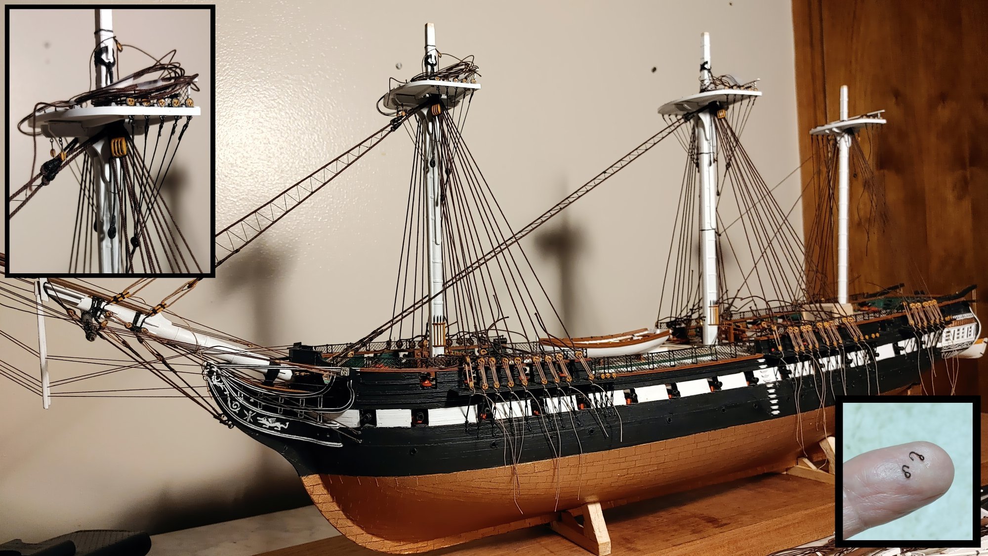
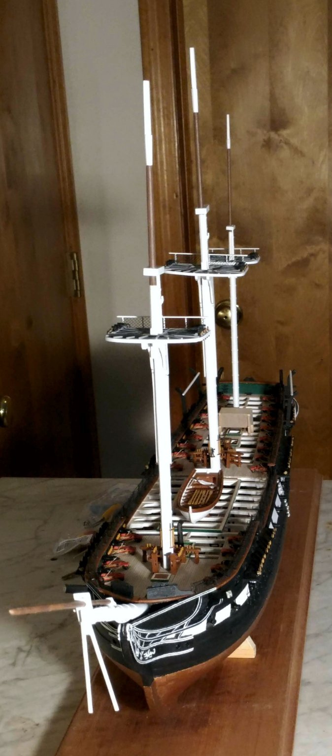
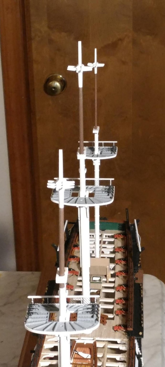
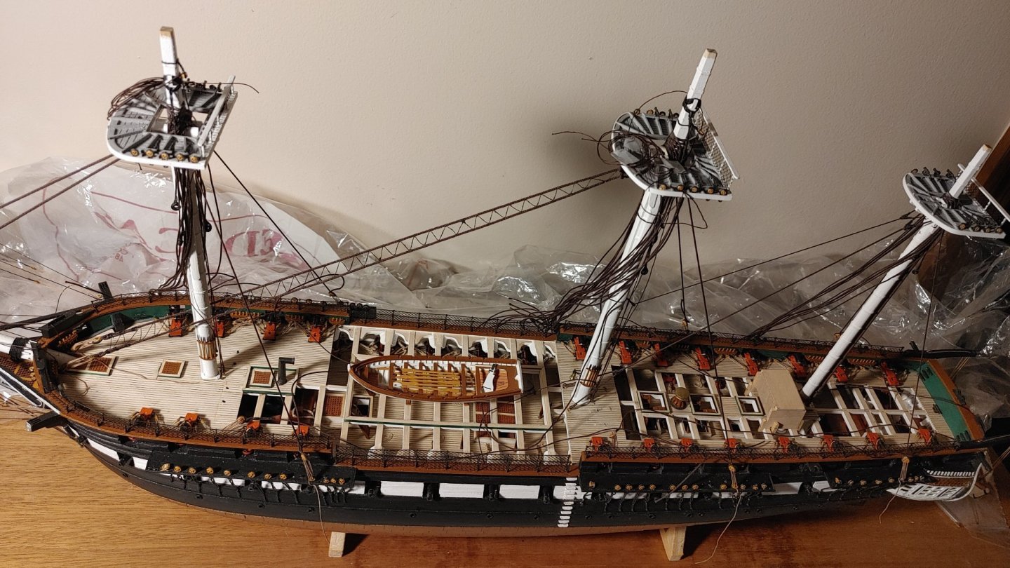
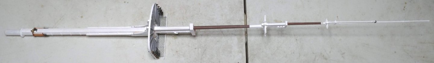
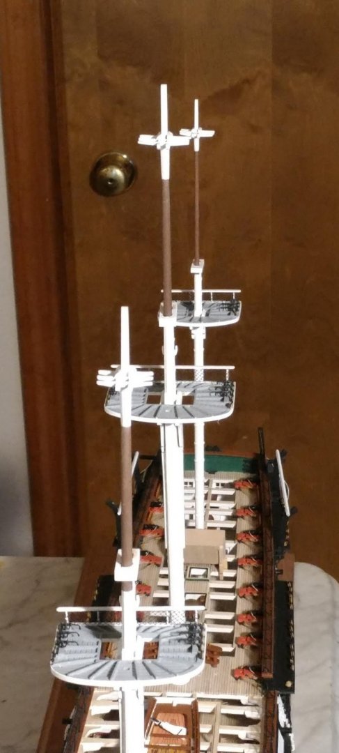
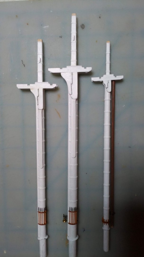
The t'gallant masts, royal masts and sky pole As I did not have confidence in my ability to render these neatly, I took these parts from the Revell model. They are more flexible which means that rigging theirs stays will be tricky. It also means that if they accidentally encounter something, they will not snap off. Here is the entire mast assembly with these parts fry fitted: Completed masts fitted on the model:

- 110 replies
-
- 5
-
-
- Bluejacket Shipcrafters
- Constitution
- (and 2 more)
-
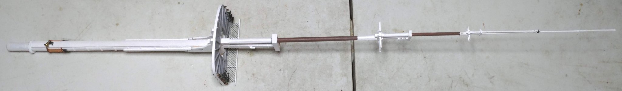
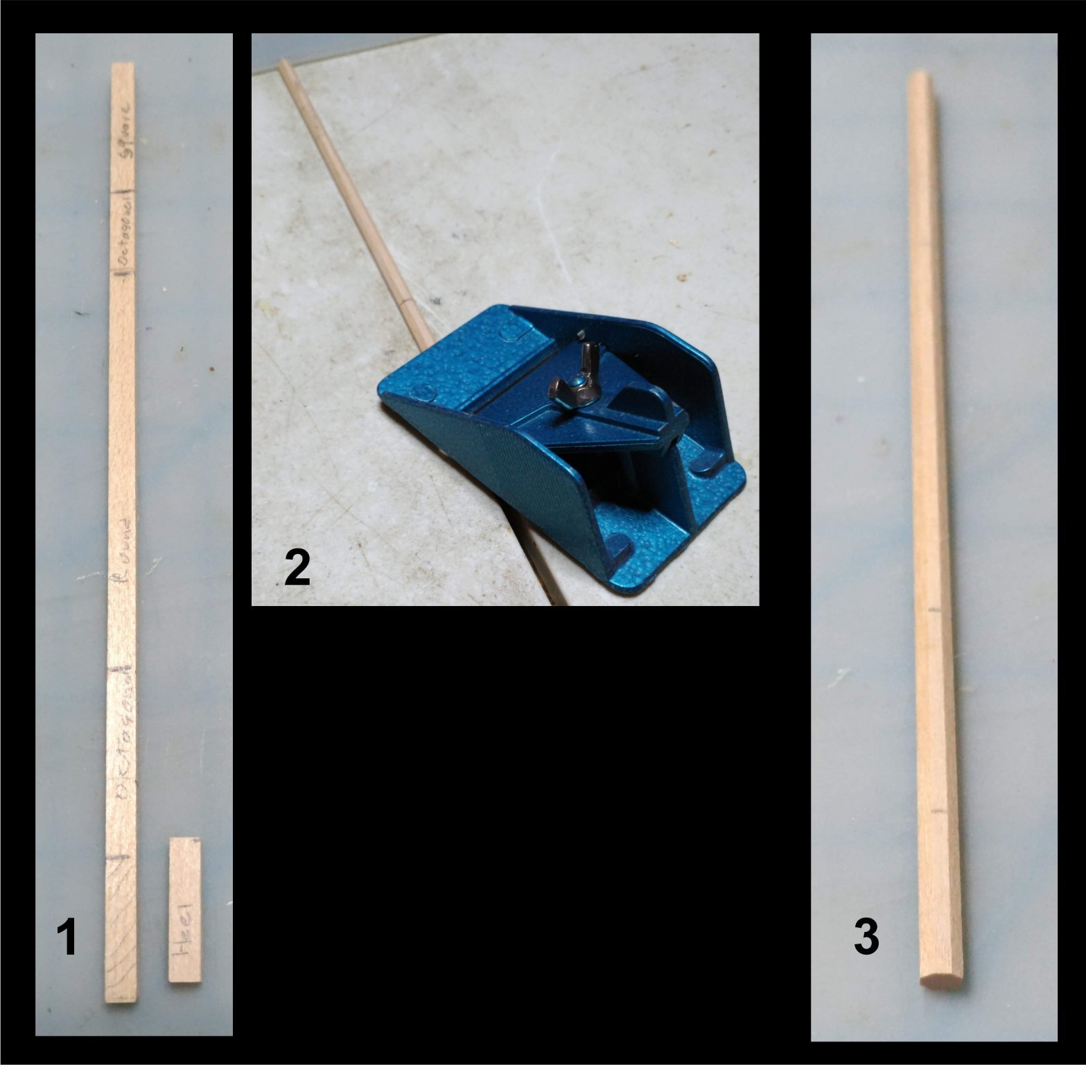
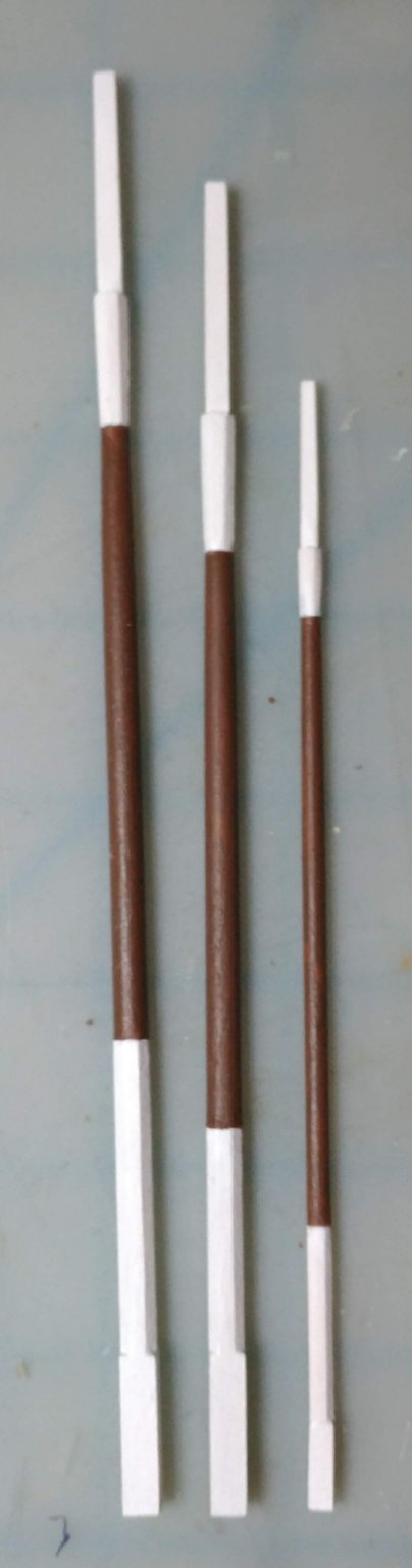
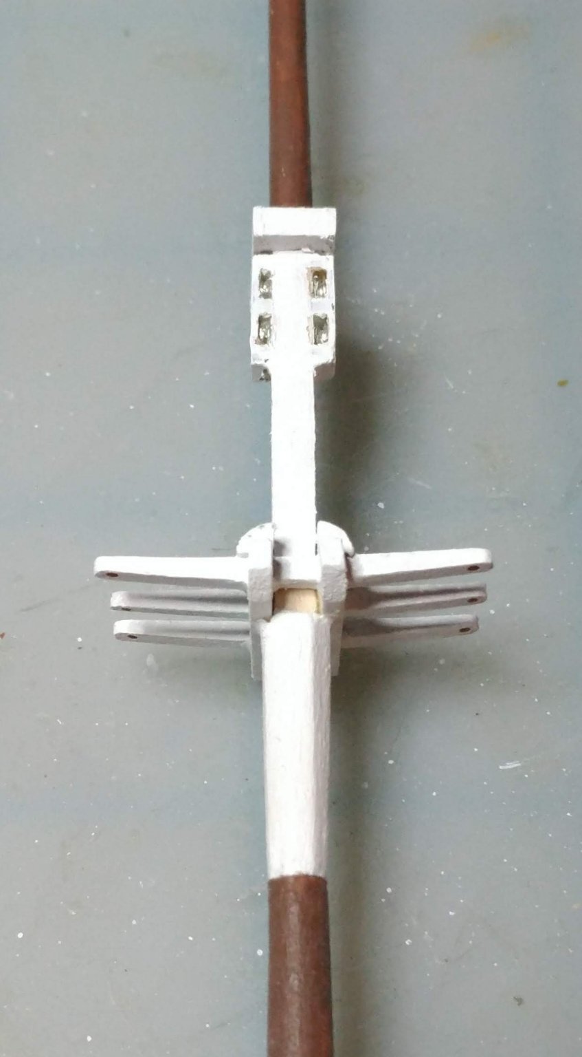
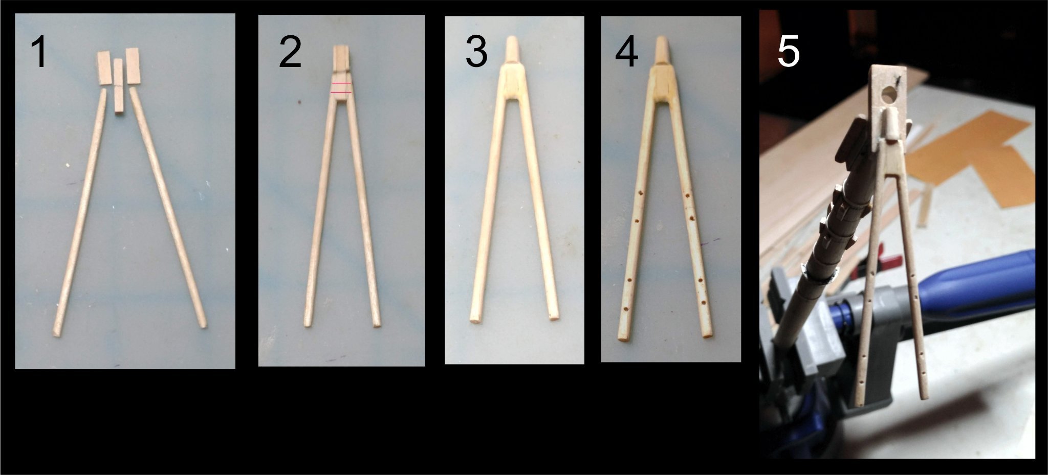
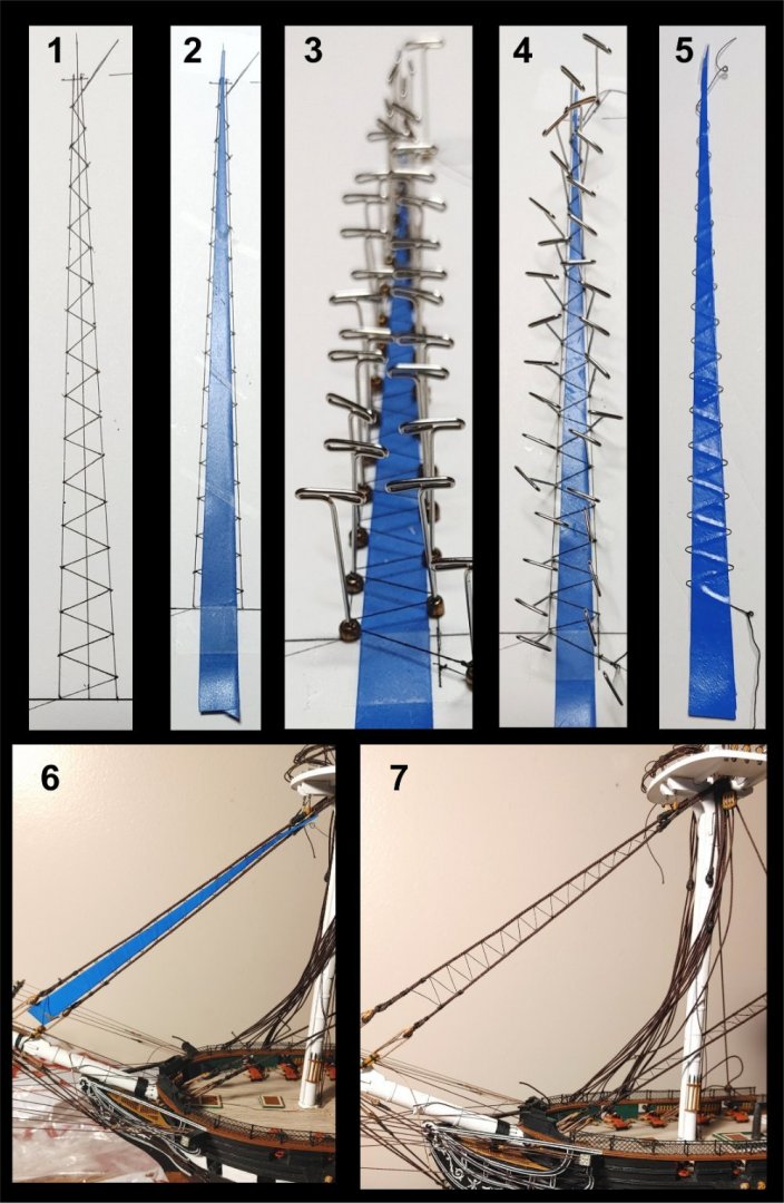
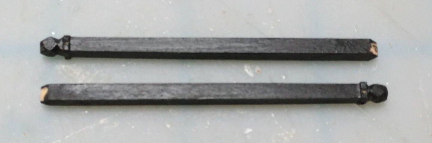
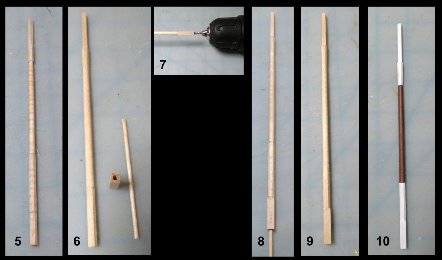
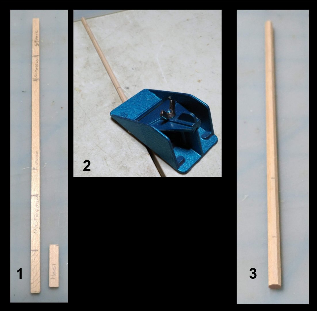
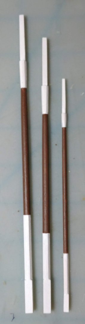
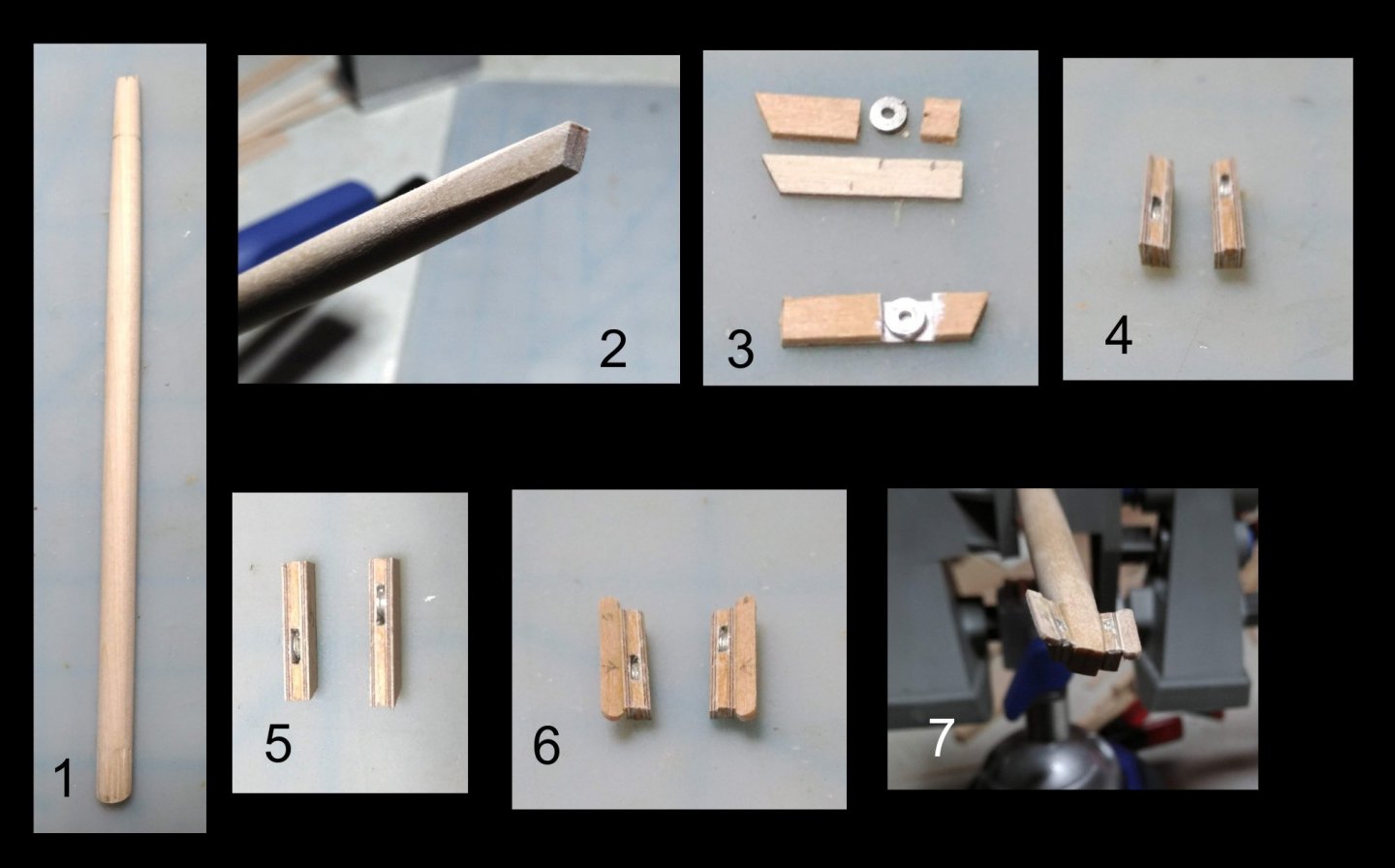
The topmasts The bottom of the topmasts are square. Above that they are octagonal, then round, then octagonal, then square. Rather than file sections square, build up with pieces, file octagonal, etc. I decided to start with square stock. Here is how I proceeded: 1. Start with a piece of square stock. Mark out the sections. Square heel is a separate piece 2, 3. Plane it to an octagonal. 5. Sand the middle section round and taper it. This was done by hand. I do not have lathe. Taper the hounds with a chisel and square the top with a file. 6. Using a drill press drill a 1/16" hole straight through the heel. 7. Glue the heel to the bottom of the mast, and, using the hole in the heel as a guide, drill into the mast itself. 8. Insert the dowel through the heel and into the mast and glue, reinforcing the joint. 9. Finished topmast. 10. Topmast painted. The three topmasts finished and painted: The topmasts dry fitted: I used two methods to make up the cross trees. In the first, I notched the trestle trees to receive the cross trees. In the second I used a composite "built up" approach: more involved, but neater. The bolsters were cut from 1/4 round stock provided in the kit. Cheek blocks were added to the topmast heads: Topmasts with cross trees dry fitted to the model:


- 110 replies
-
- 5
-
-
- Bluejacket Shipcrafters
- Constitution
- (and 2 more)
-
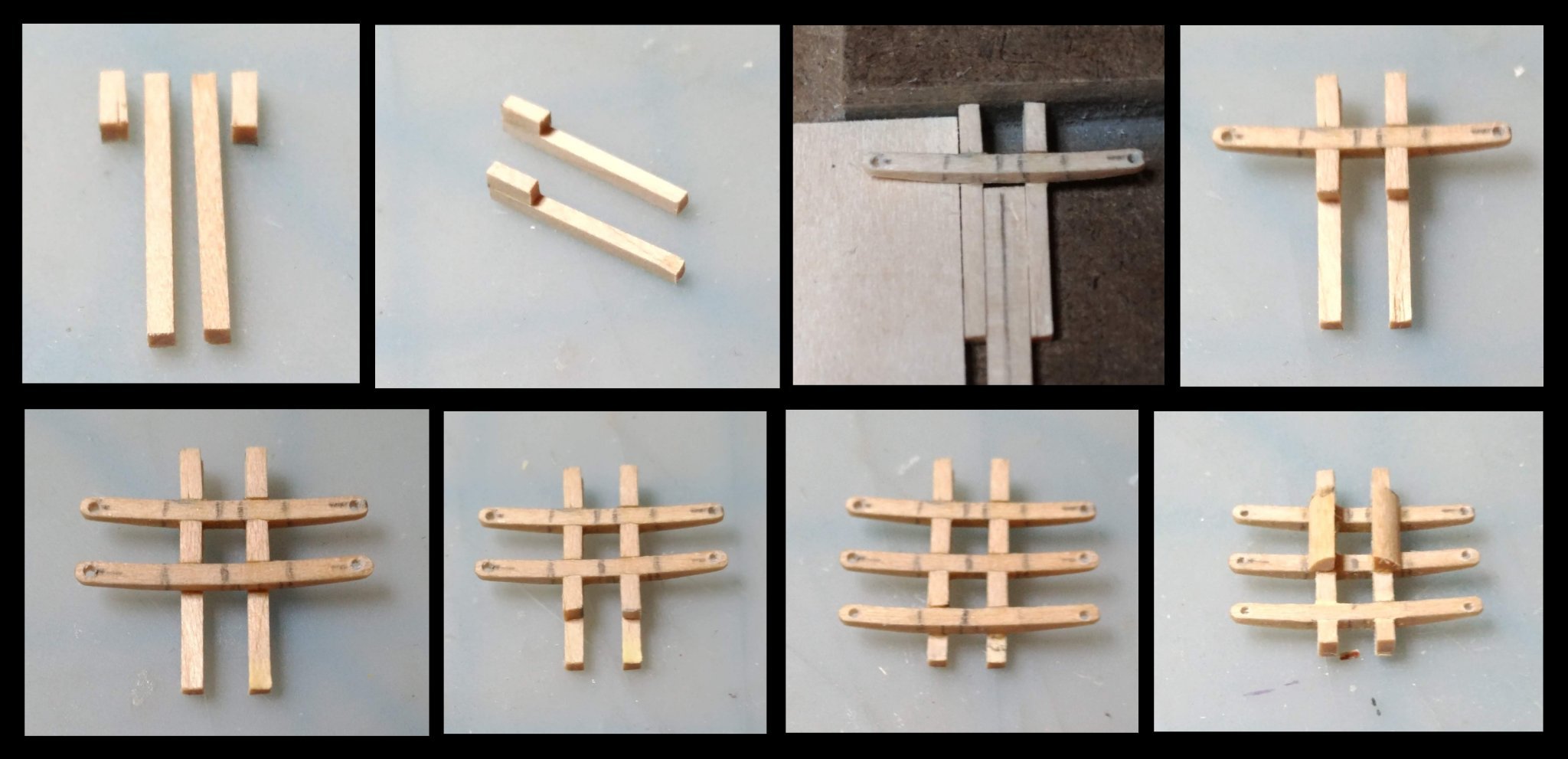
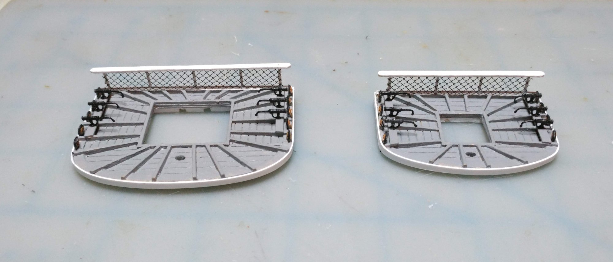
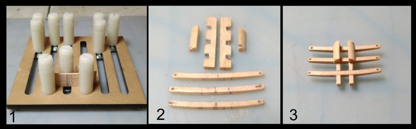
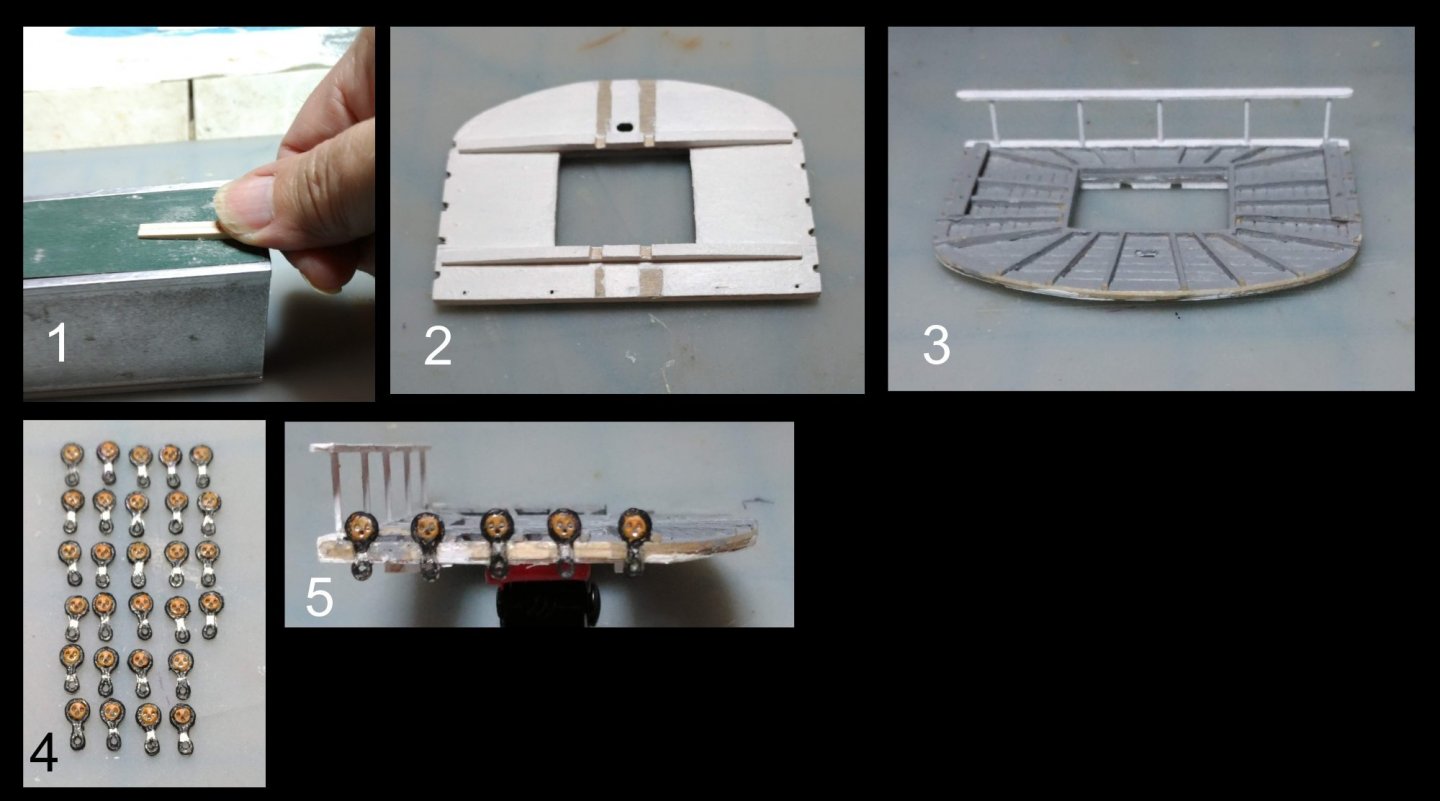
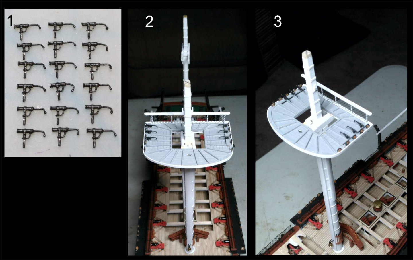
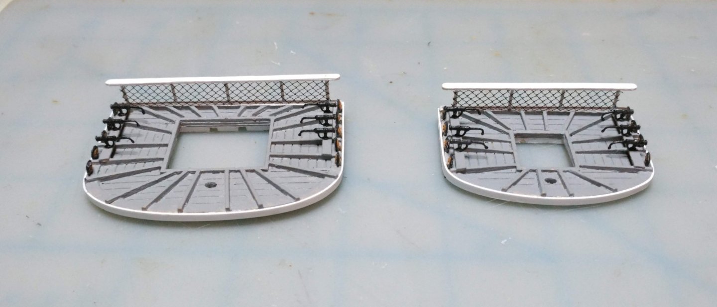
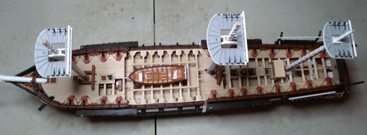
The fighting tops The fighting tops are scratch in this kit. Drawings and plans are given in the instruction manual and in the plan sheets. Heads up: The mizzen top plan in the plan sheet is asymmetrical. I also looked at the plans in the Marquardt AOS, and the tops in the Revell model. The upper surface of the top should be painted gray, so I used scribed decking to show planking detail. I used 1/64" birch plywood to stiffen the structure. The rim and the battens bordering the lubber hole were of 1/32" basswood stock, giving a total of 3/32" thickness. The problem with this arrangement was that the backing and decking tended to curl upwards in a direction perpendicular to the grain of the first and third layer of the plywood. Clamping it into a vise as the glue dried helped. Floor battens were of 1/32" by 1/16" stock. They taper from a 1/16" height at the outer rim to 1/32" to match the batten which borders the lubber hole. Notches were cut to receive the stropped deadeyes. Here is a composite illustrating this: Battens added to the sides will house the swivel guns. The 1/16" thick batten on the aft border will support the rear rail assembly. In the next composite, photo 1 shows one the crosstrees being tapered. The rest, I believe is self explanatory. The next composite shows the cast swivel guns, and the finished top dry fitted to the mast with its outer rim of stryrene, and the aft rail netting (same as the hammock netting) installed: A view of the finished fore and mizzen tops: All three tops dry fitted:

- 110 replies
-
- 5
-
-
- Bluejacket Shipcrafters
- Constitution
- (and 2 more)
-
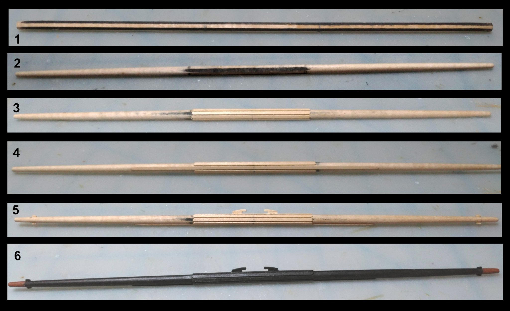
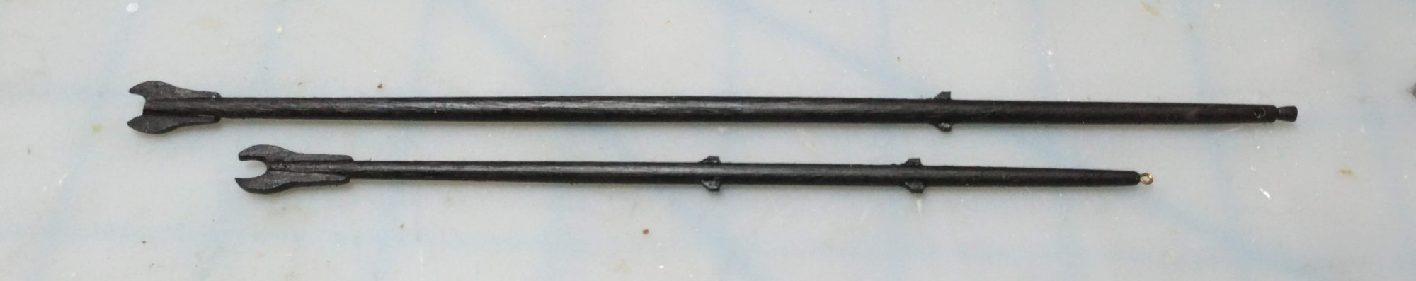
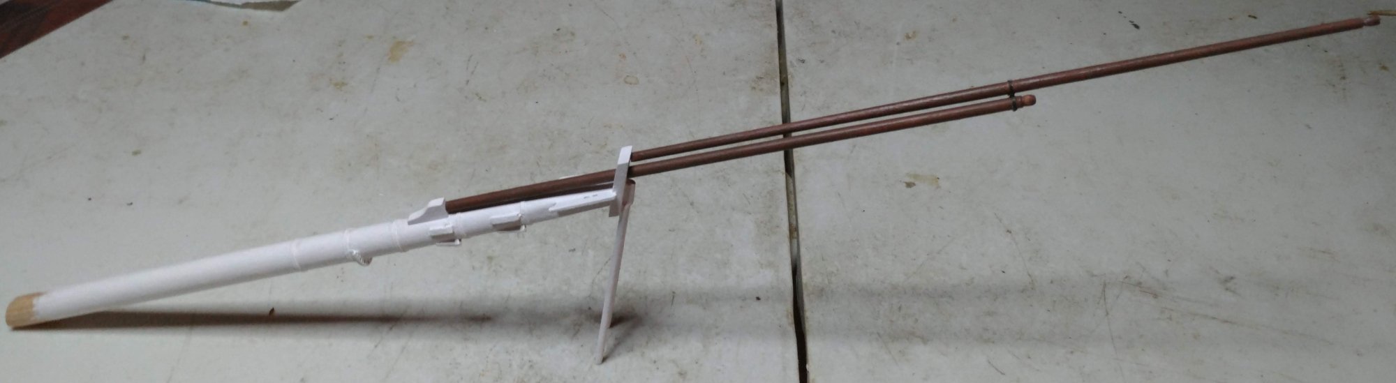
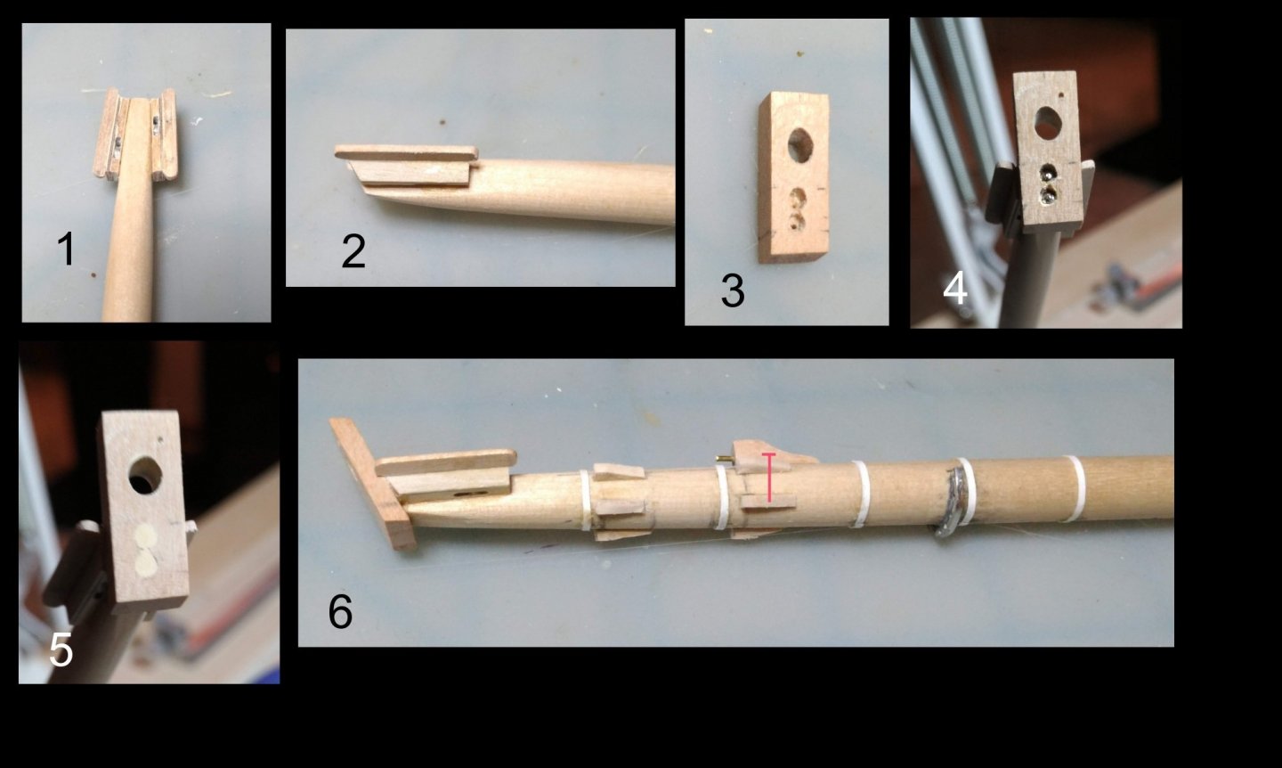
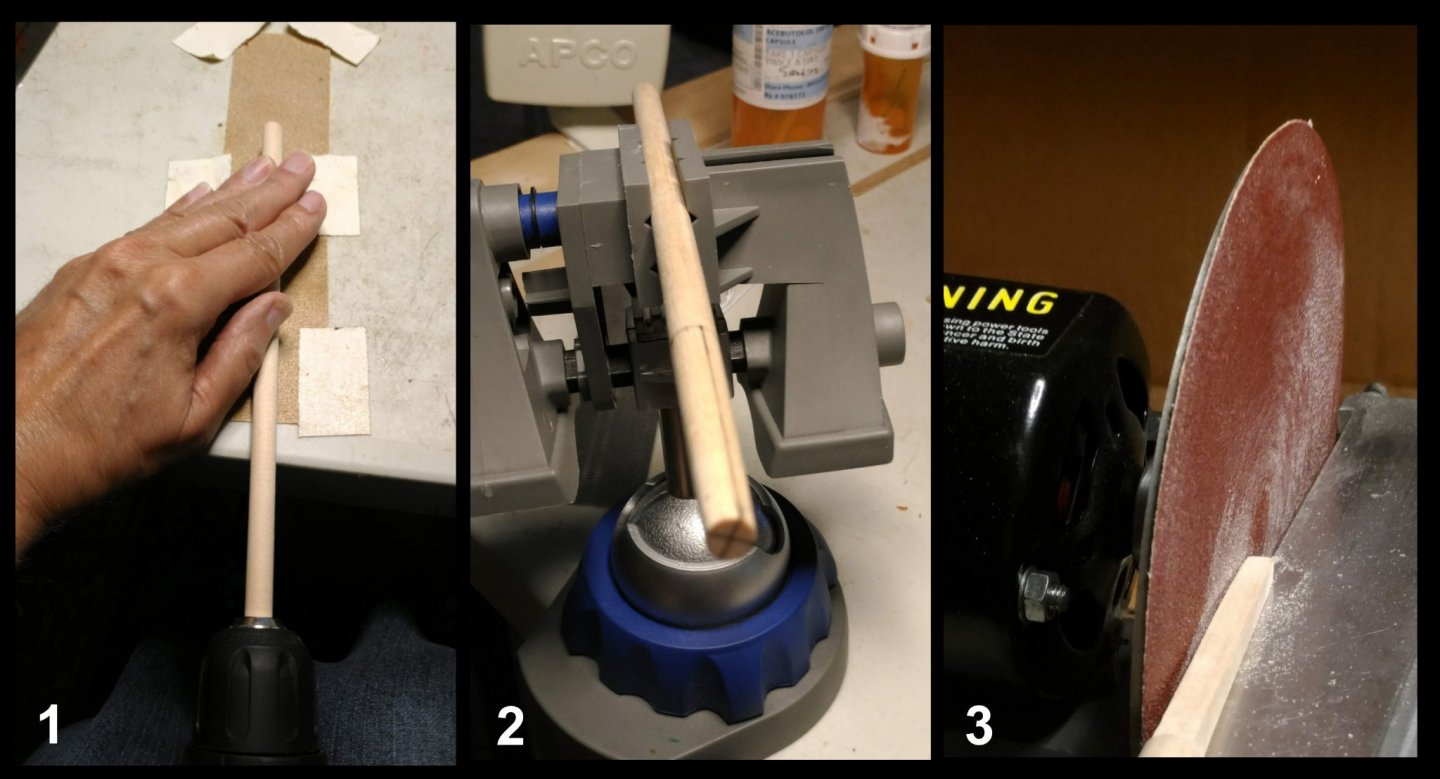
The Bowsprit and jib booms The bowsprit was made from 3/4" birch dowel. The hoops were made from 67 lb card stock as in the masts. Here is a composite illustration of the construction sequence: 1. The bowsprit tapered using the same method as in the masts. 2. Flat sections sanded in using the disc sander. 3. Top - components of the bee block: two 1/32" strip of basswood, 2 strips of 1/32" birch plywood ( If I had it to do over, the outboard layer would be 1/64" plywood.), and a cast metal sheave from BJ, sanded to a 1/32" thickness Bottom: two layers assembled. 4, 5. Bee blocks assembled. Upper surface beveled to get the proper angle. 6. Completed bees. Inboard edge of the Outboard wing component beveled to compliment the angle of the upper edge of the bee blocks. 7. Bees glued onto flat sections of the bowsprit. 1, 2. Two more views o the completed bees 3, 4, 5. Bowsprit cap showing method of securing it to the end of the bowsprit using reinforcing pins 6. Hoops, forestay cleats, jib boom step, and fairlead installed. The kit does not include a fairlead. I ordered a spare spider ring from BJ. The holes, originally intended for belaying pins serve very well as fairleads. I cut a section out of the side which did not have holes and bent the ring outward very very carefully then glued it to the bowsprit with epoxy. Construction of the dolphin striker. The red lines in photo 2 indicate reinforcing pins. Completed bowsprit painted and dry fitted on the model: Jib booms installed: Each boom was tapered by holding it against sand paper taped to the table, and moving back and forth while constantly rotating it. The jib boom cap is a strip of card stock around each of the two booms, connected by a wire fitted into holes drilled into both booms to receive it.

- 110 replies
-
- 3
-
-
- Bluejacket Shipcrafters
- Constitution
- (and 2 more)
-
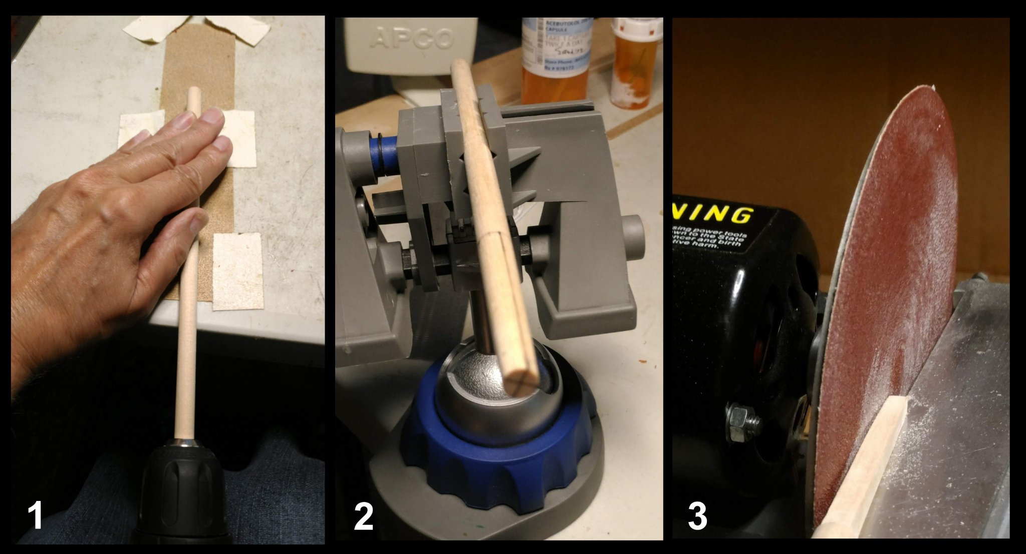
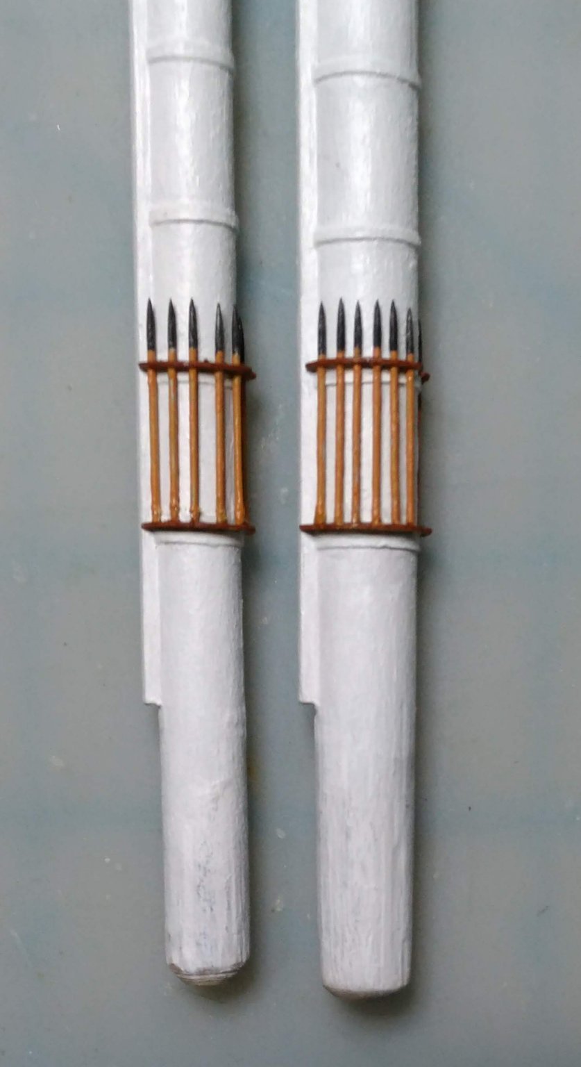
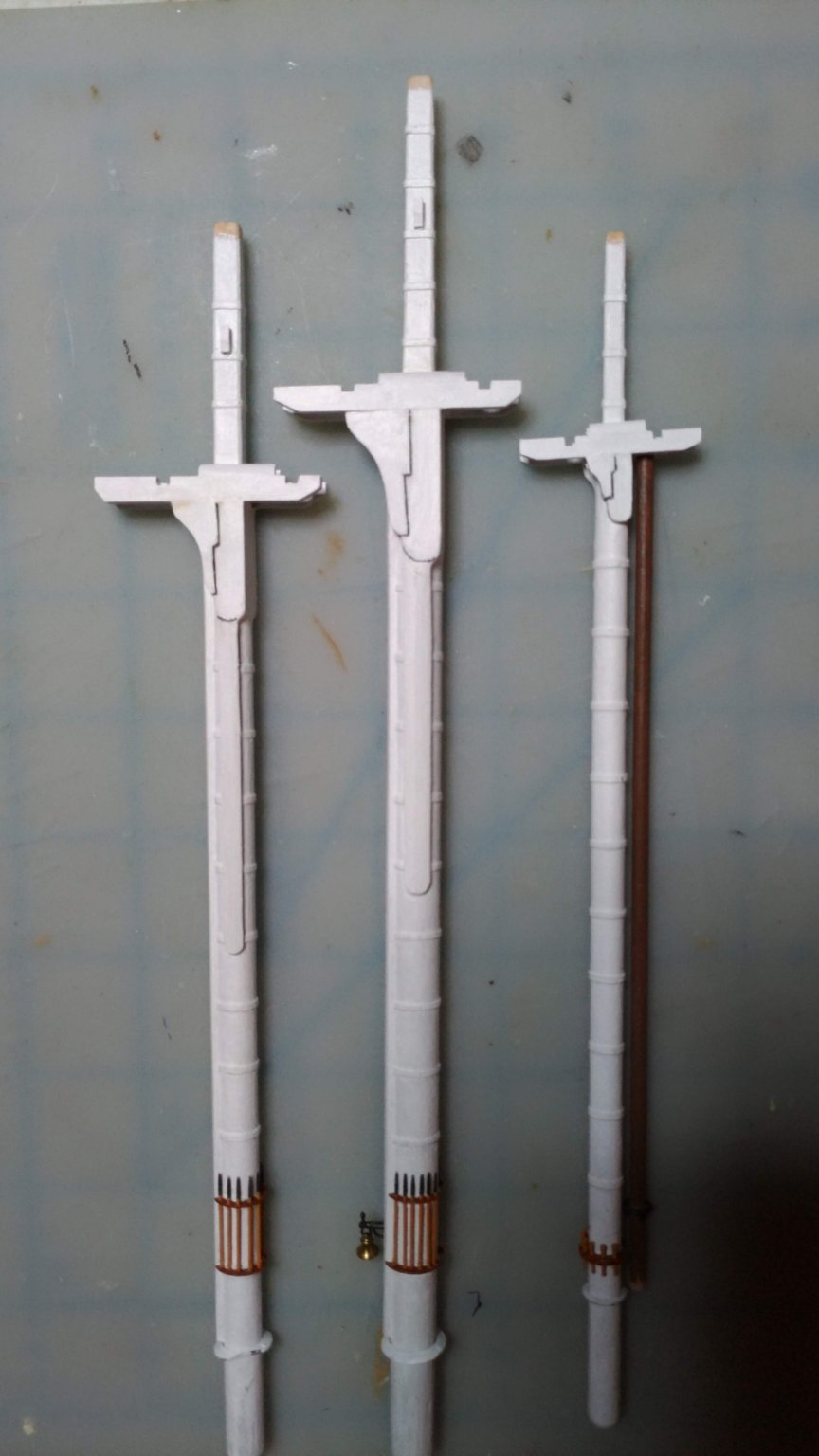
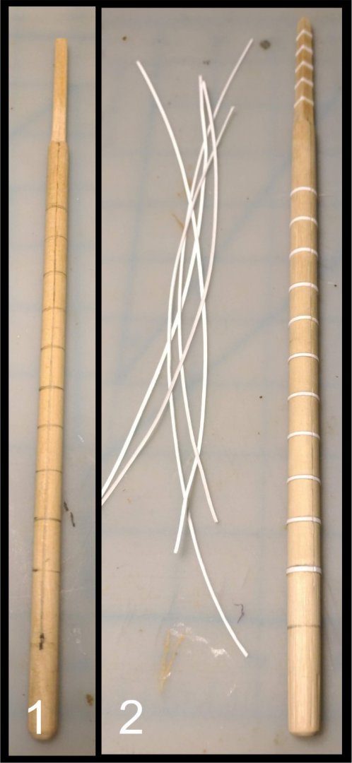
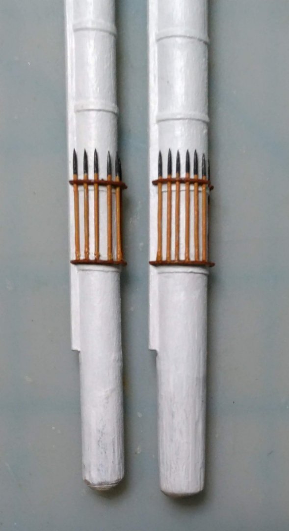
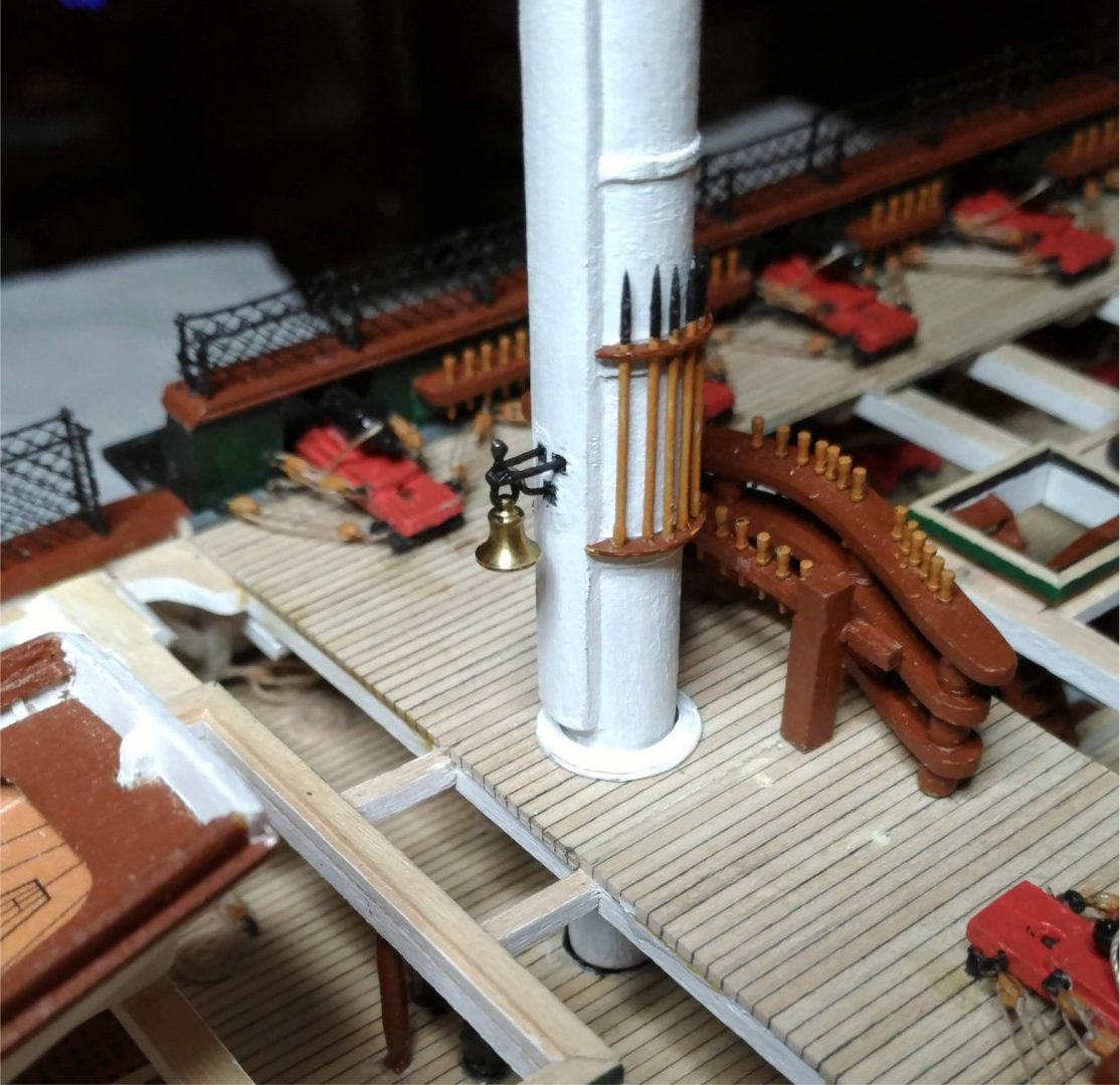
The masts Bluejacket provides birch dowels for masts and spars. It turns out that dowels that are not warped are very hard to come by. Fortunately the provided dowels were straight for enough of their length to be usable for the lower masts. Here are some composite photos showing my method for constructing them. 1. Tapering the mast using an electric drill to turn it, and holding the mast against sand paper taped to the table top. 2. The tapered end marked in preparation for squaring the mast head. 3. Squaring the mast head using a disc sander ( hand operated for the more exacting and delicate shaping). 1. Locations of the mast hoops marked out. 2. Strips of 67 lb card stock cut, then glued to the mast using PVA with the seam located in front to be covered by the paunch. 1. Drawing taken from the downloaded MS Constitution instruction manual showing the method for constructing the cheeks and paunch which I adopted. 2. Strips of 67 lb card stock glued in between the hoops to provide a good base for the gluing of the cheeks and paunch. 3. Gluing 1/16" by 1/16" basswood strips to the mast. 4. Strips glued awaiting the filling in of the cracks between the strips with diluted Elmer's wood filler. 5. Filler applied, then sanded down to the correct thickness and contour to form the paunch. 6. A side view of the paunch before and after filling in the gap between the outer edge of the paunch and the mast. 1. Two hound/bib units incorporating the hounds and bibs glued together with rubber cement and shaped, so they would match each other. 2. The two units separated and inscribed with a chisel to simulate the joint between the hounds and bibs. 3. The hounds and bibs glued to the mast, then filled in with wood filler. 4, View of the mast with hounds, bibs and paunch 5, 6. Two views of the mast with the hounds/bibs andcheeks in place. 7. Completed mast with jeer cleats installed. 8. Closeup of the masthead showing jeer cleat construction. 9. All three masts completed and painted. Photo-etched brass boarding pike racks are provided. Boarding pikes are metal castings. Heads up: Only the very tip of the metal boarding pike will fit through the holes in the top rack, so I substituted #17 pins with their heads cut off, and came up with this arrangement: The ship's bell is a brass casting. I mounted it on the mast using wire bent to simulate the present arrangement as closely as I could. The bell swings free. I decided to make and mount the trestle trees at this time. Heads up: The plan for the trestle trees on the mast plan, and the corresponding drawings on the tops plans do not match, The notch into which the aft cross tree fits is farther aft on the mast plans than it is in the tops plans. Here they are installed on the masts: Here are the completed masts dry fitted on the model.


- 110 replies
-
- 6
-
-
- Bluejacket Shipcrafters
- Constitution
- (and 2 more)
-
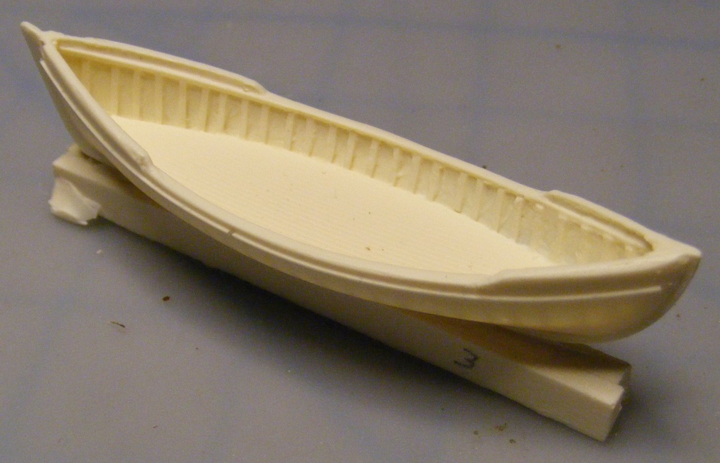
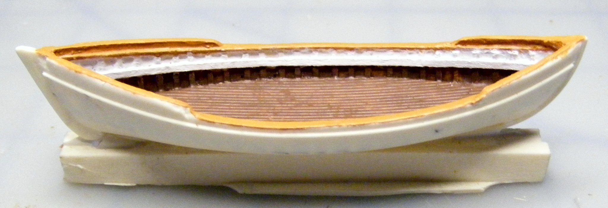
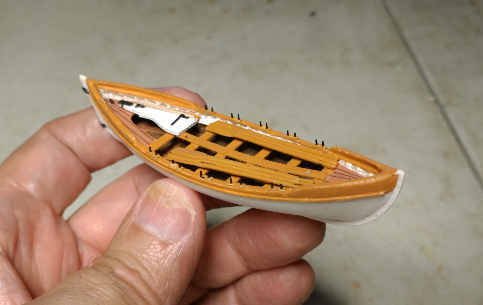
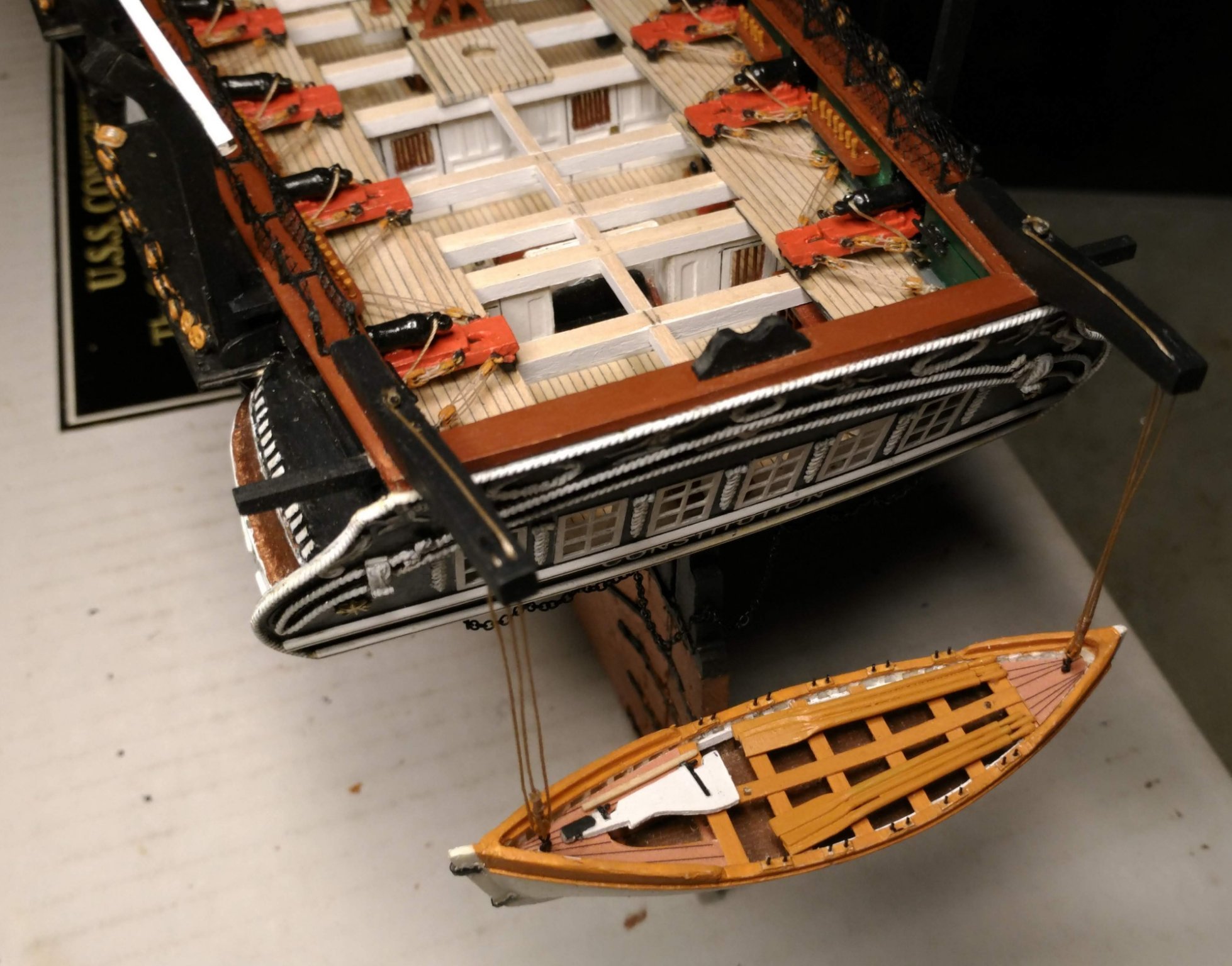
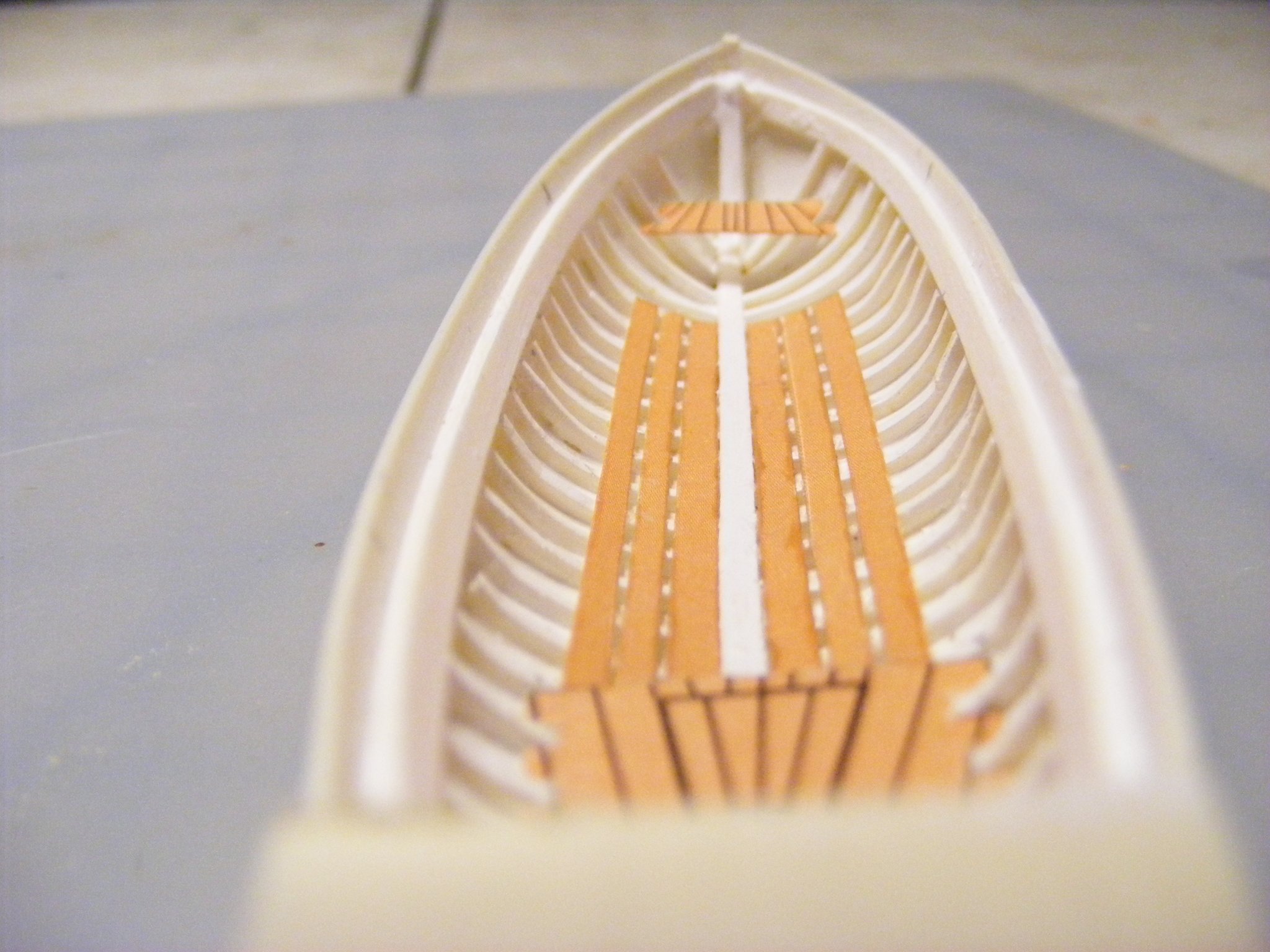
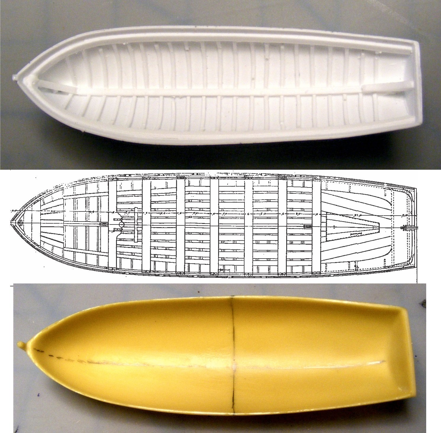
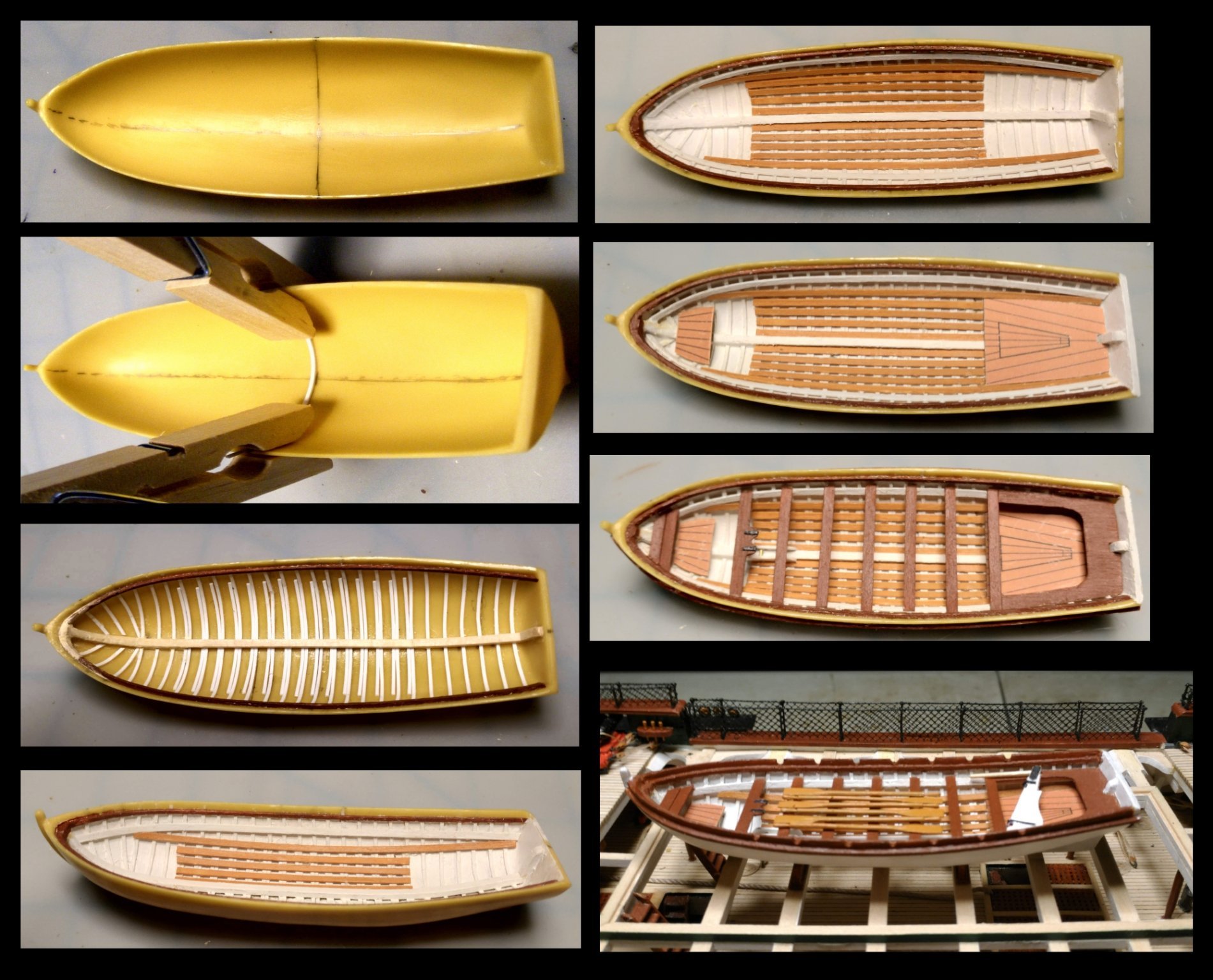
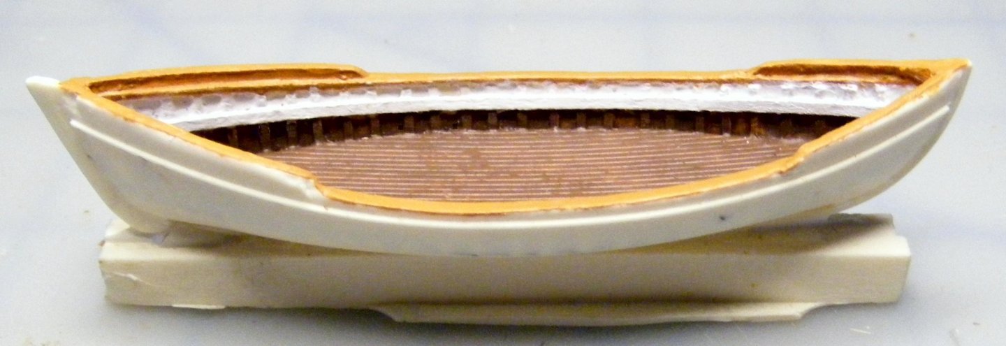
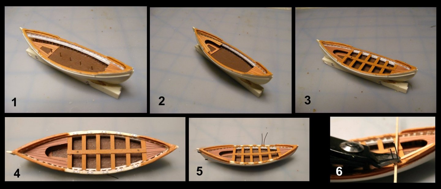
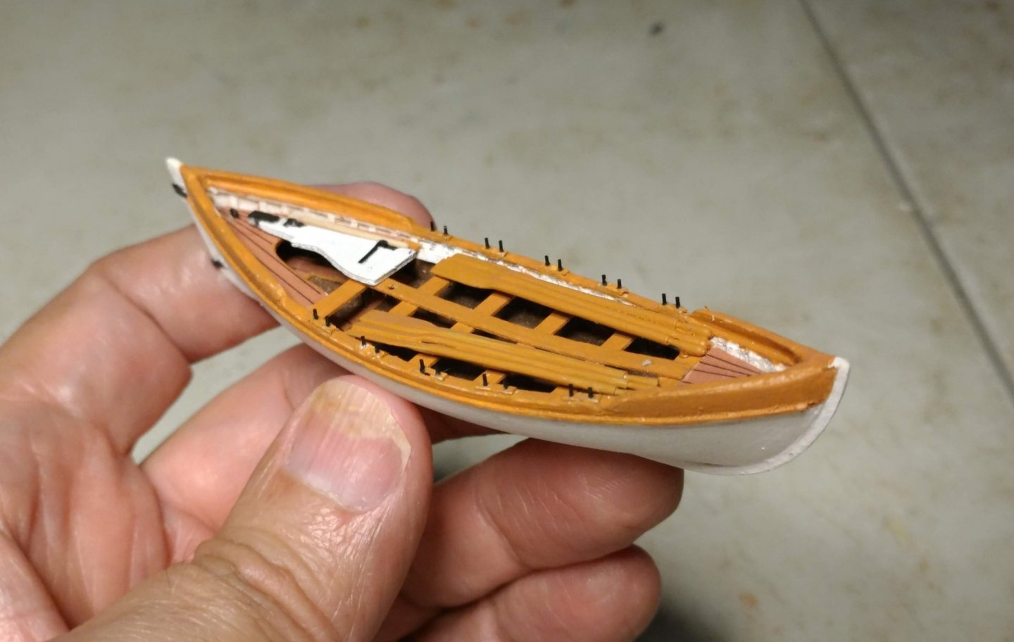
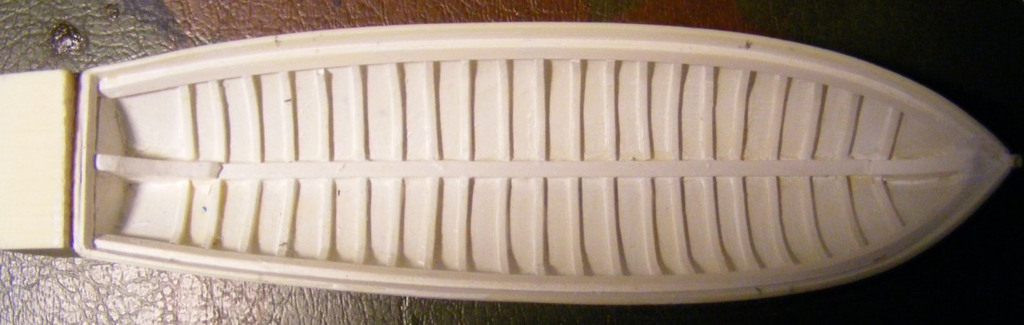
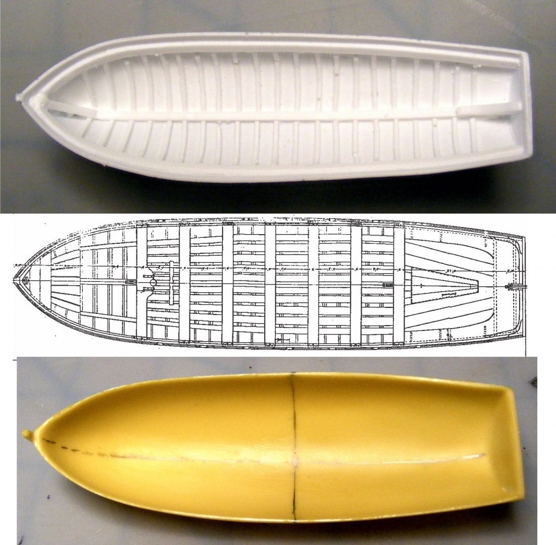
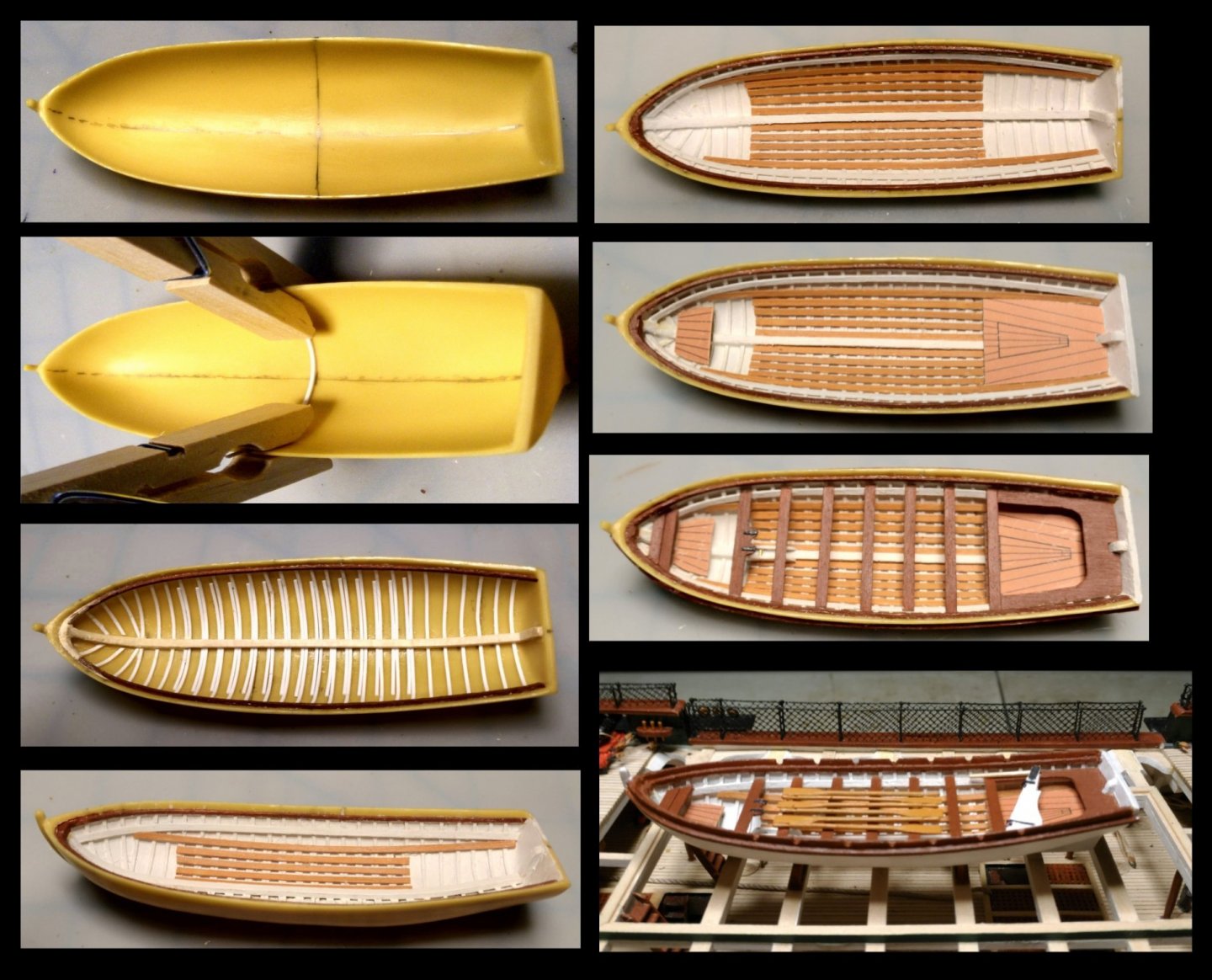
The boats The boats in this kit are unique in that the outer shells are of cast resin. They are not bread-and-butter like the MS Constitution, nor are they the mini POF kits you see in many other kits. The resin castings are of the outer shell, and have the ribs, keel, keelson, and inner-outer stem detail molded in. Other internal details are scratch. Heads up: These castings have gaps, holes, and many irregularities which require fine tools and putty to correct. Here is a casting of one of the gigs: In this case, decking replaces the keelson detail. Actually this is one of the better castings, and looks pretty good until you paint it. As always there is nothing like a coat of paint to reveal every flaw. This photo shows the boat with the wooden riser installed. To get really clean detail requires, I believe, a fine rotary tool with dentist drill size bits and great skill, neither of which I have at present. The following composite illustrates the construction of the inner details: 1. Stern foot-waling and breast decking installed. Rather than assemble these from separate pieces, I made up the plank detail in Corel Draw using the plans scanned from the instruction book and sized to scale as a template, matched the background color to the MS Bulwarks Brown, printed it on brochure paper, and glued it onto 1/64" birch plywood backing. Wire was used to simulate thwart stanchions. 2. Stern sheet bench added. 3. Thwarts and centerboard made from 1/64" birch plywood. 4. Thole plates made from styrene strip glued to the gunwale top. 5. Black wire inserted into the holes. 6. Wires clipped off to the right height (approx.) to make the tholes. The next composite shows the construction sequence of the rudders. The oars are provided as metal castings. These are of excellent quality and require very little cleanup of flashing. Here is a shot of the completed boat with gudgeons installed: Captain's gig installed hung from the stern davits. The tackles are long, but I was not about to obscure the transom detail. Here is a shot of the provided pinnace resin casting: The casting was badly misshapen, but I managed to straighten it out by running hot water over it and bending it back into shape. The rib detail is very clean on this one, so I began construction of the inner details in the same way that I did with the gigs (whaleboats) until... Head up: There is a serious flaw in the design of this boat. The inboard gunwale strake is quite wide, so that the thwarts need to butt up against the lower edge of it. These two timbers do not meet at the bow the way they should: This means that the forward thwarts and the breast decking are going cant downwards to starboard. This was unacceptable to me, so I ordered a boat shell from Caldercraft that I thought most closely approximated the correct size and shape. Here is a composite picture which compares the BJ cast (top), the plan given in the instruction book (center), and the Caldercraft shell (bottom) The Caldercraft cast is clean. No sanding, filing or filling required here, but I did have to do the ribs, keelson, stemson, etc. myself. Here is a composite showing of the construction of the interior details: Ribs were styrene strips. Breast foot waling and stern sheet waling are done the same way as in the gigs. Loose foot waling, thwarts, breast decking, and stern sheet bench are made from 1/64" birch plywood.


- 110 replies
-
- 5
-
-
- Bluejacket Shipcrafters
- Constitution
- (and 2 more)
-
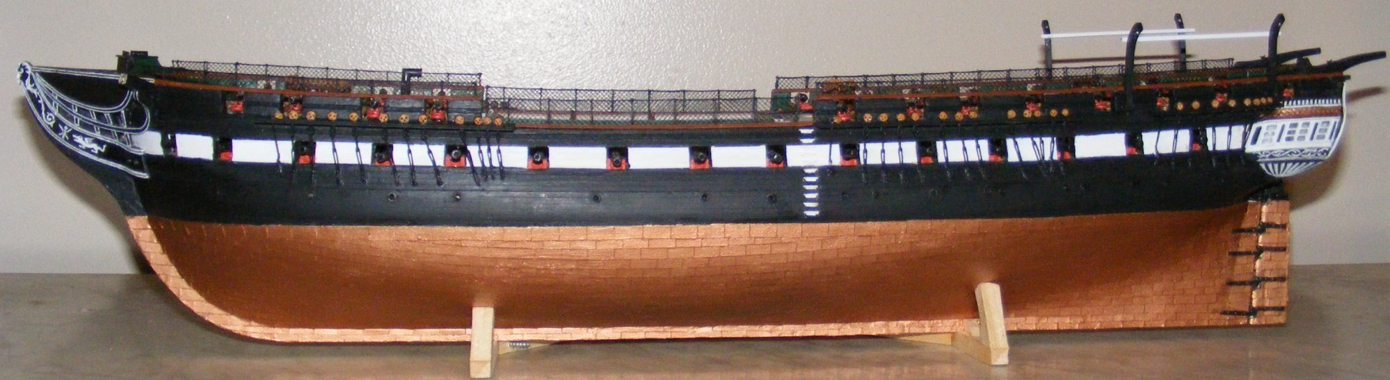
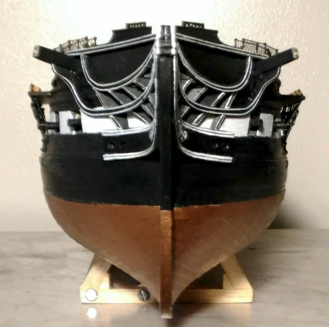
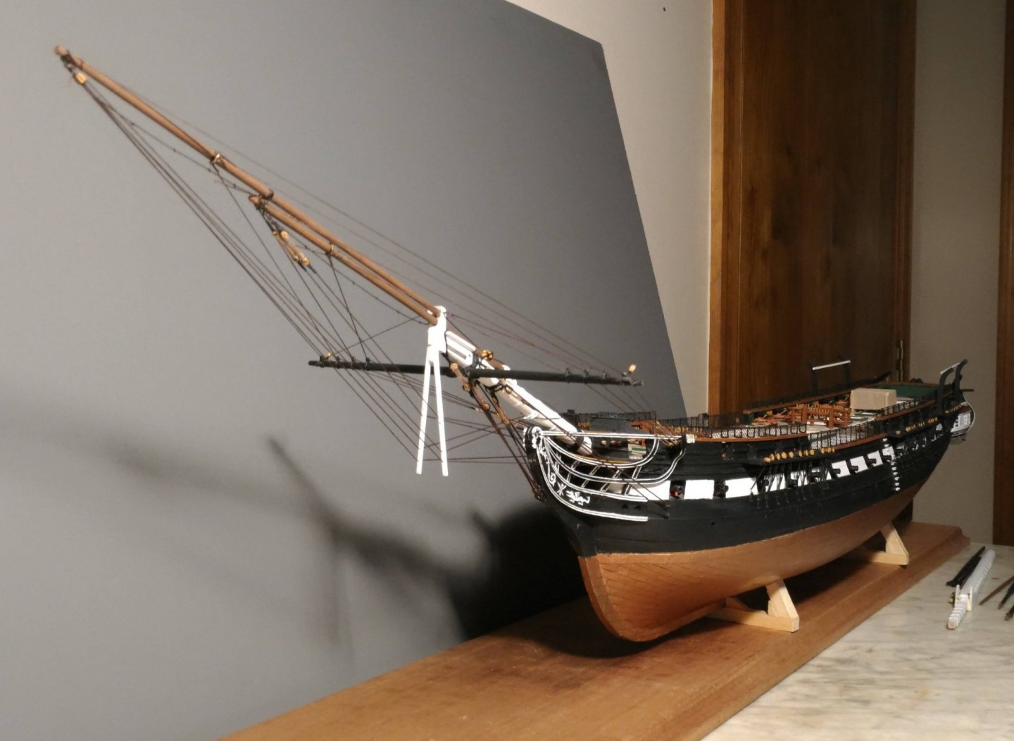
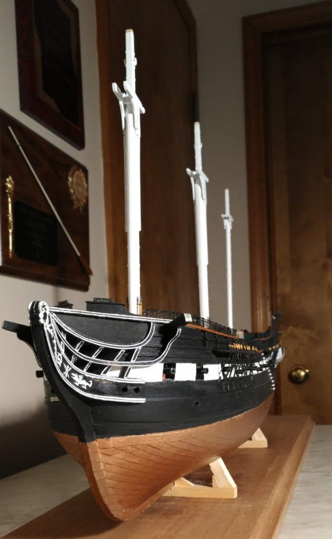
Milestone reached This pretty much completes the hull. The only thing missing is the foretack boomkin. That comes much later. Here are some shots of the completed hull: I seem to have lost the shot of the stern that I took at that time, but here is a more recent one with the captain's gig installed: It's a better photo anyway.


- 110 replies
-
- 6
-
-
- Bluejacket Shipcrafters
- Constitution
- (and 2 more)
-
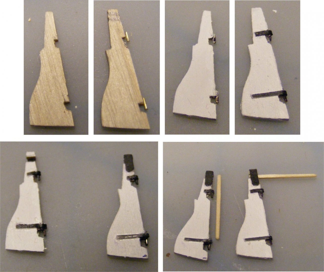
The boat davits The construction of the quarter davits uses the layering procedure that was used in the catheads, and in the fore topsail sheet bitts. There are three layers, two of which are 1/64" birch plywood with a third layer of 1/16" basswood sandwiched in between. This gives a scale 9" thickness which is specified in the plans. Two sheaves are used here. It would be nice to have a "septum" between the two sheaves, but I saw no way of doing that without exceeding the width specified in the plans. These davits will be temporarily glued to the hull with rubber cement so that they can be removed when the standing rigging is done. The stern davits were constructed in much the same way, except that each sheave has its own slot.
- 110 replies
-
- 4
-
-
- Bluejacket Shipcrafters
- Constitution
- (and 2 more)
-
The hammock cranes and netting The instructions recommend installing the hammock cranes last. This would have meant working with them behind the shrouds and ratlines which would have been very difficult, so I did them here. Brass photo-etched hammock cranes are provided. Initial painting of these cranes was done on the sprue with the eyes at the top left natural so as not to restrict the reeving of the line through them. The instructions recommend that slots be cut in the caprail to receive these, but I opted for drilling holes in the rail and inserting the pins at the bottom in and glueing it with CA gel. As I said, these holes should have been drilled before the caprail was installed, but that's the way it goes. Once in place filler was used to fill in any gaps and the joints retouched with MS Hull Umber to match the caprail. Here is a shot of the model with the cranes installed. Also visible is a specially designed box that protects the delicate helm assembly. The line I used for the top of the cranes was Bluejacket #1654, 0.020". Being smooth, it rove easily through the eyes. I stiffened it with liquid CA which gave the assembly much needed stability. White netting is included in the kit, but I wanted black, so I got some 1/16" netting at Joanne's which looked perfectly in scale to me. I used contact cement and CA gel to secure it to the cranes, touched it up with black paint as needed, and trimmed the top. This is the result:
- 110 replies
-
- 7
-
-
- Bluejacket Shipcrafters
- Constitution
- (and 2 more)
-
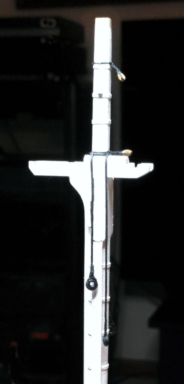
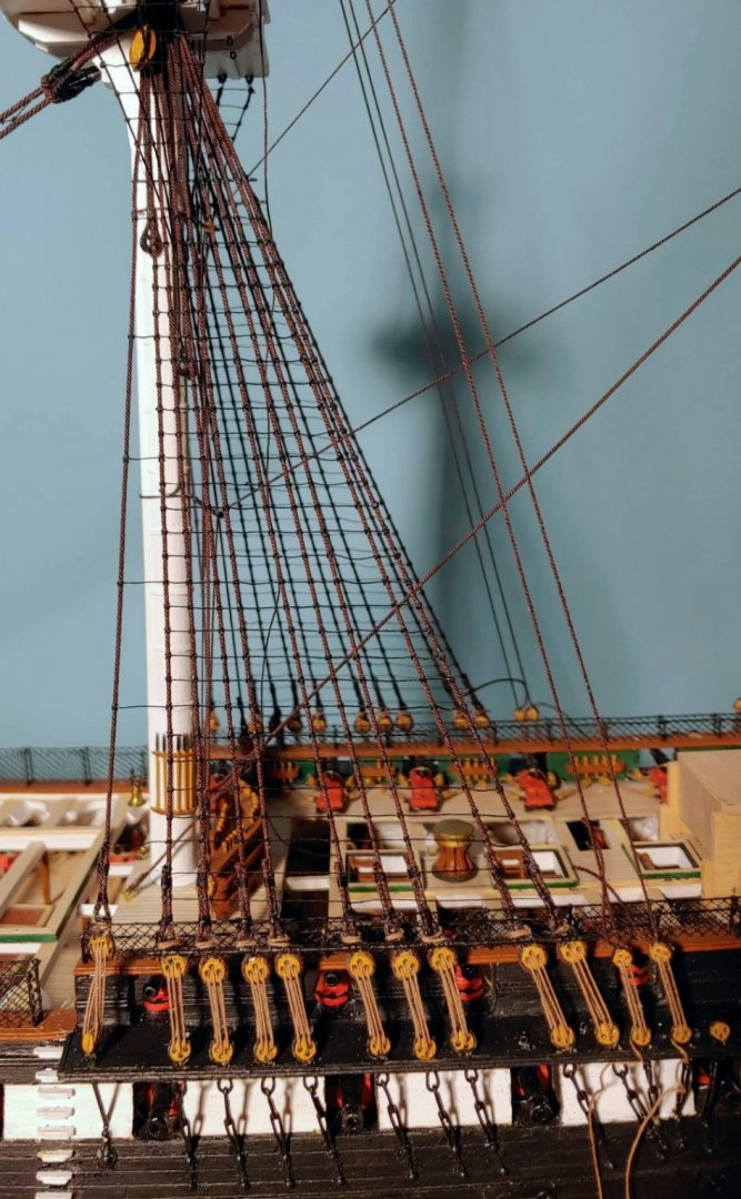
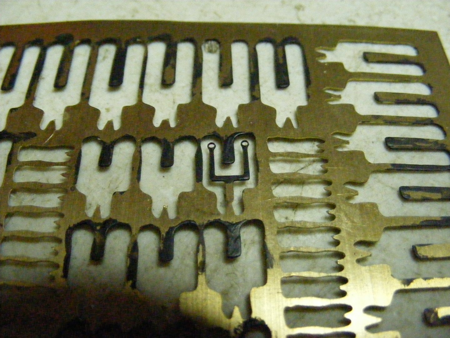
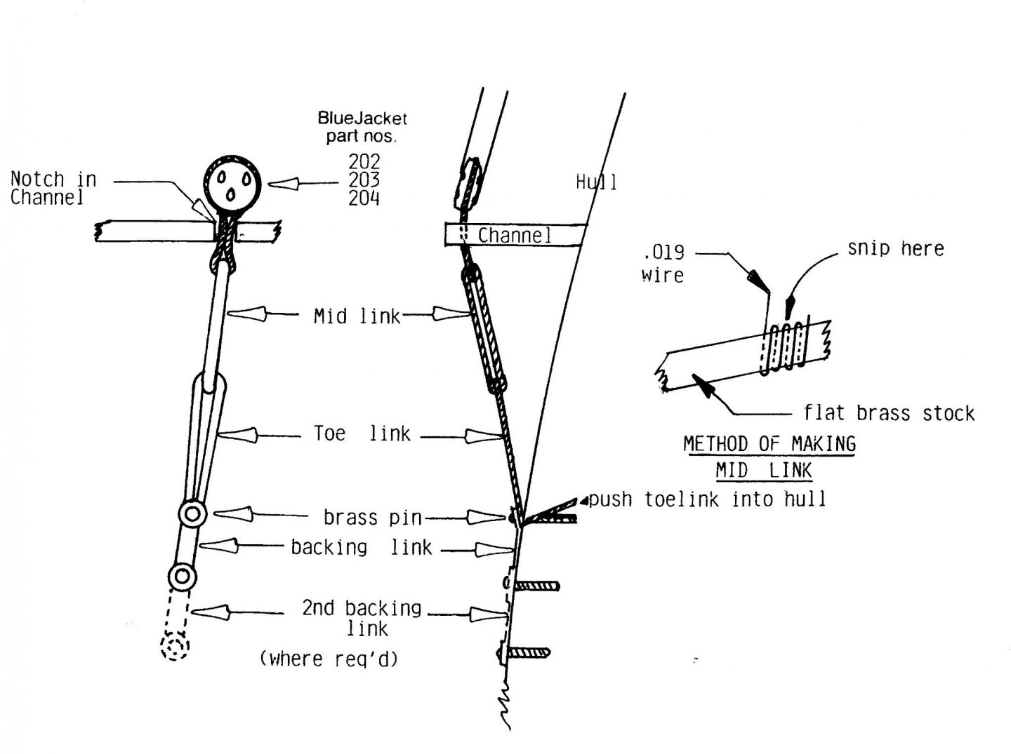
The chains The kit includes the following components for making up the chains: metal stropped deadeyes, photo-etched brass backing links, and a coil of wire. The construction of these chains is illustrated in the book: Notches were cut in the channels, the castings were glued in with CA gel (I would use black epoxy if I had to do it over). You do not want these things to move while constructing the chains or when reeving the lanyards. They were then enclosed with a 1/16" double bead strip from BJ. When securing the back links to the hull, I applied a drop of liquid CA, and let it wick in thinking that any shine could be covered up with a black paint touch-up. It turns out that I could apply 99 coats of paint and the shine will still be there. Lesson learned. I should have applied a tiny dab of black epoxy to the end of each pin instead. Fortunately, the shine is not as obvious on the port side which is the side I plan to display. I am, however, happy with how the mid links and toe links came out. The provided castings look fine from a normal viewing distance, but, as you can see, anomalies become obvious when viewed in extreme closeup. This is also true of nearly every other aspect of my model, so they fit right in.
- 110 replies
-
- 2
-
-
- Bluejacket Shipcrafters
- Constitution
- (and 2 more)
-
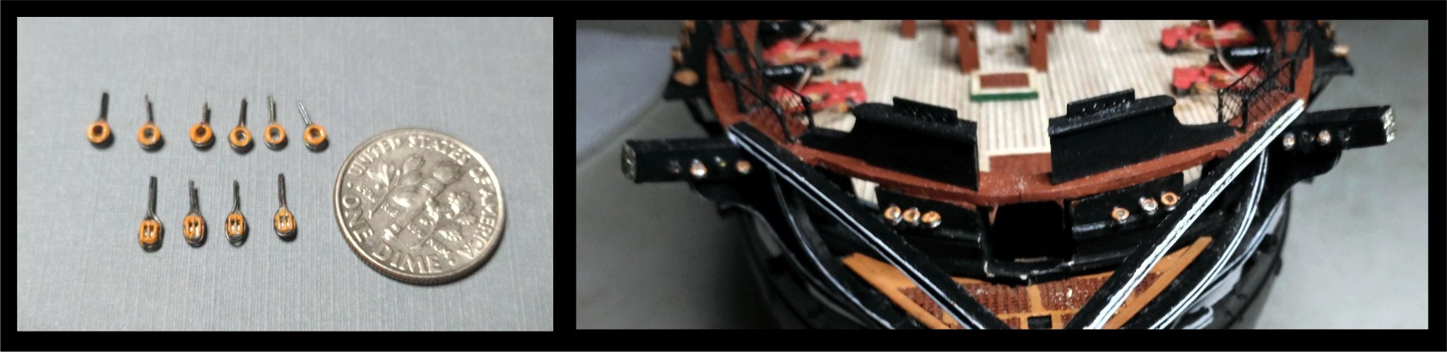
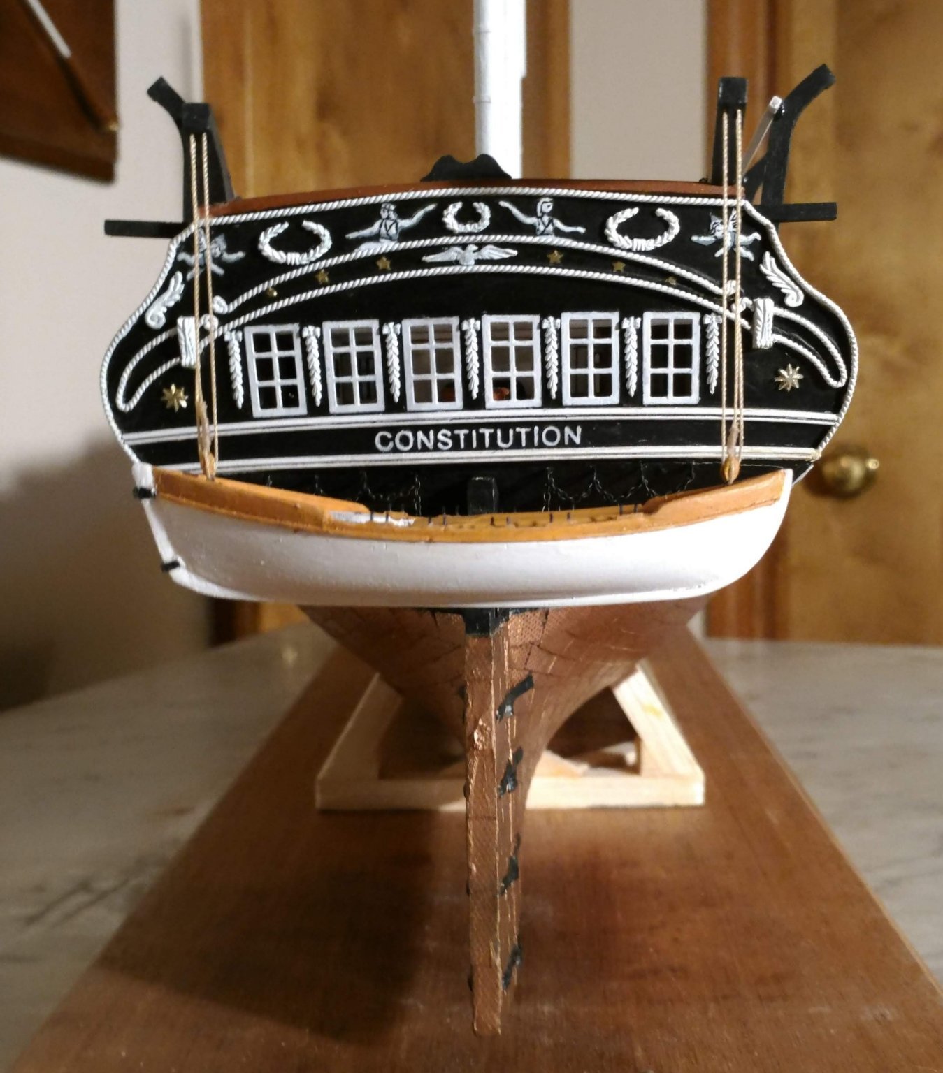
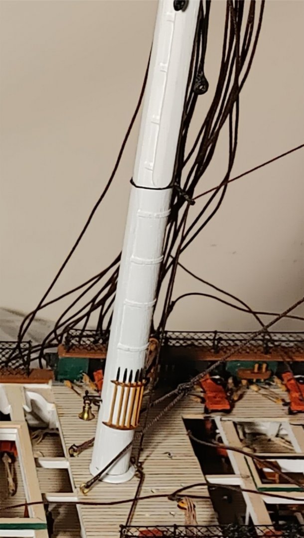
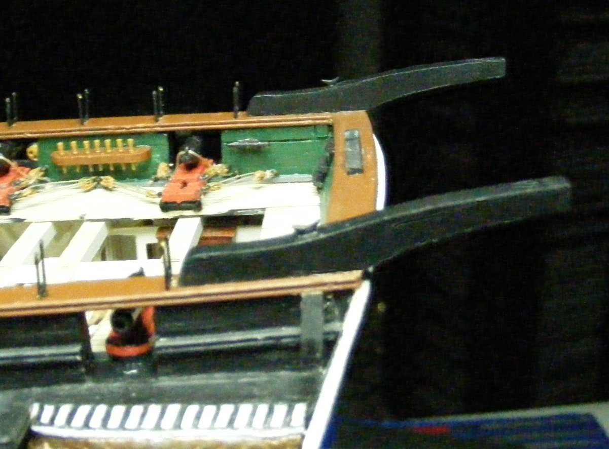
The Knightheads The side elevation of the hull indicates the presence of the knightheads protruding above the caprail, but does not give much detail. I made it to look like the present one, since most other bow details replicate the present appearance. Luckily, I was able to find a photo online showing a sailor standing between the two knightheads. Using a figure from the Revell model, I was able to approximate the height. the fairleads on top are metal strips from BJ cut to length and drilled.

- 110 replies
-
- 1
-
-
- Bluejacket Shipcrafters
- Constitution
- (and 2 more)
-
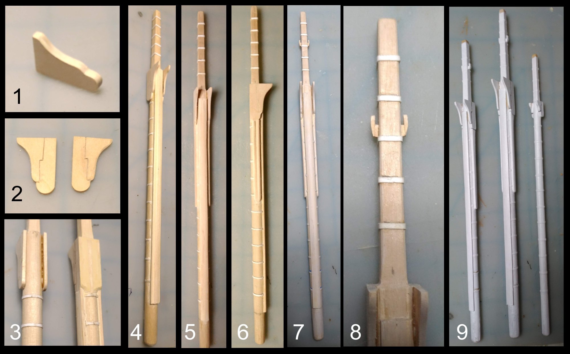
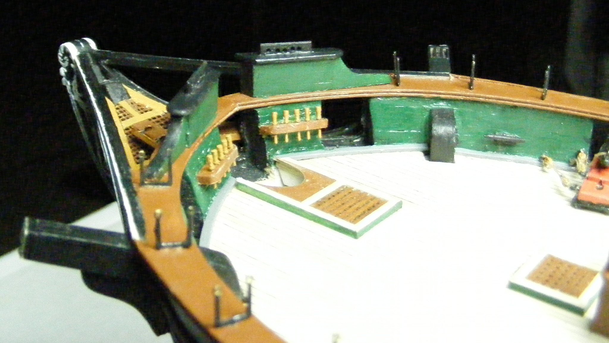
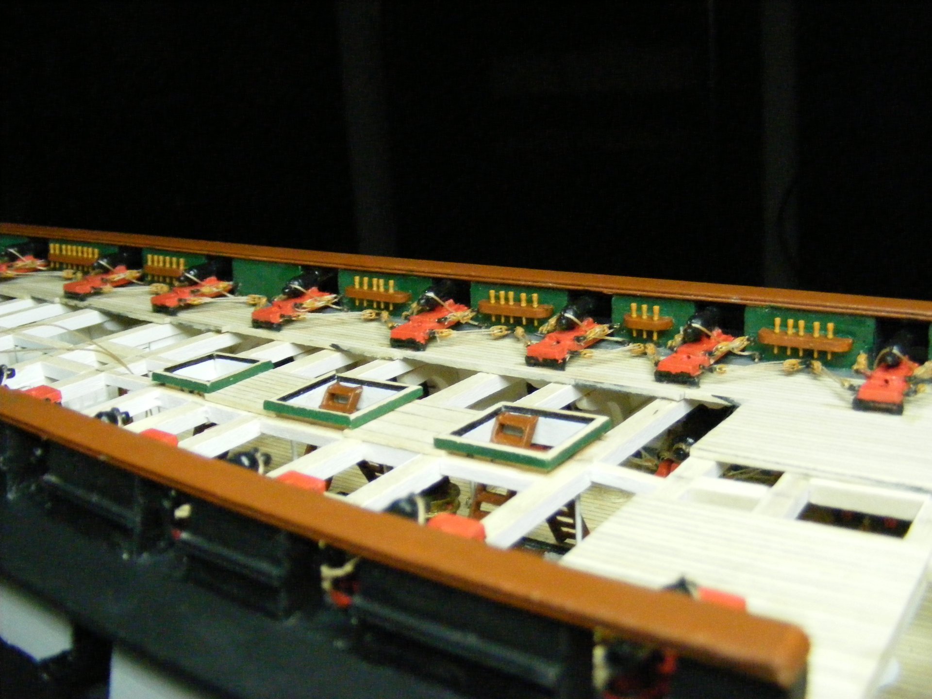
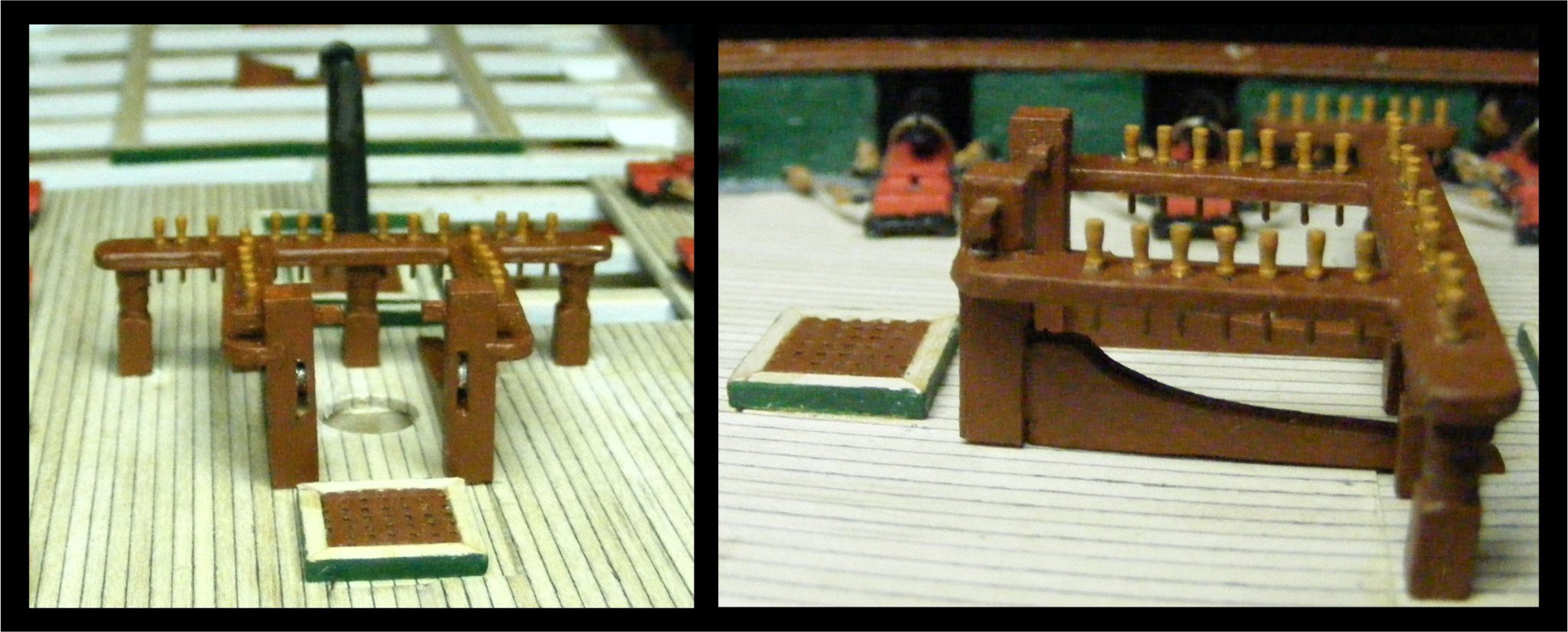
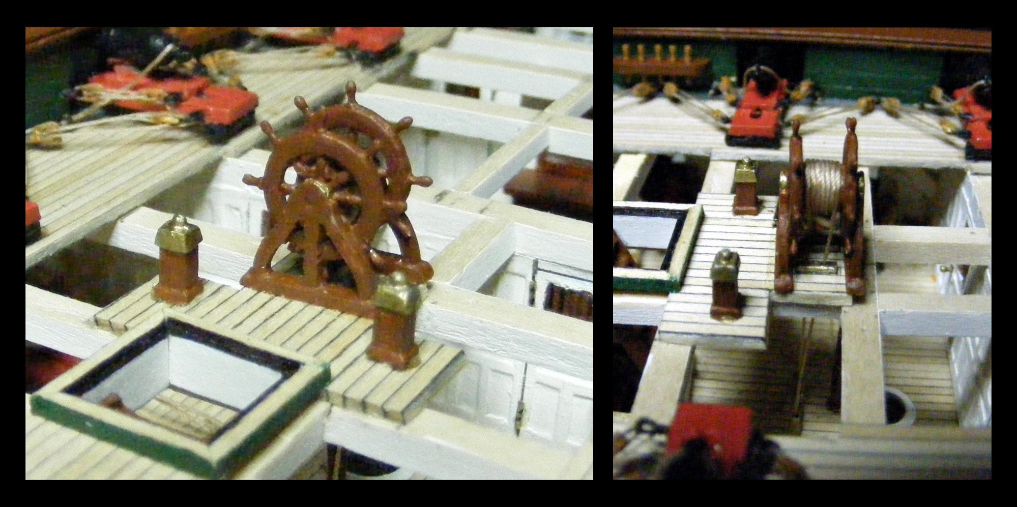
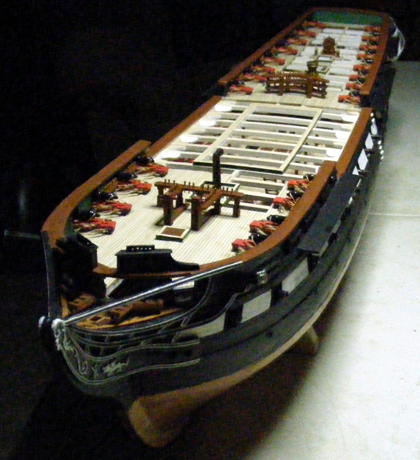
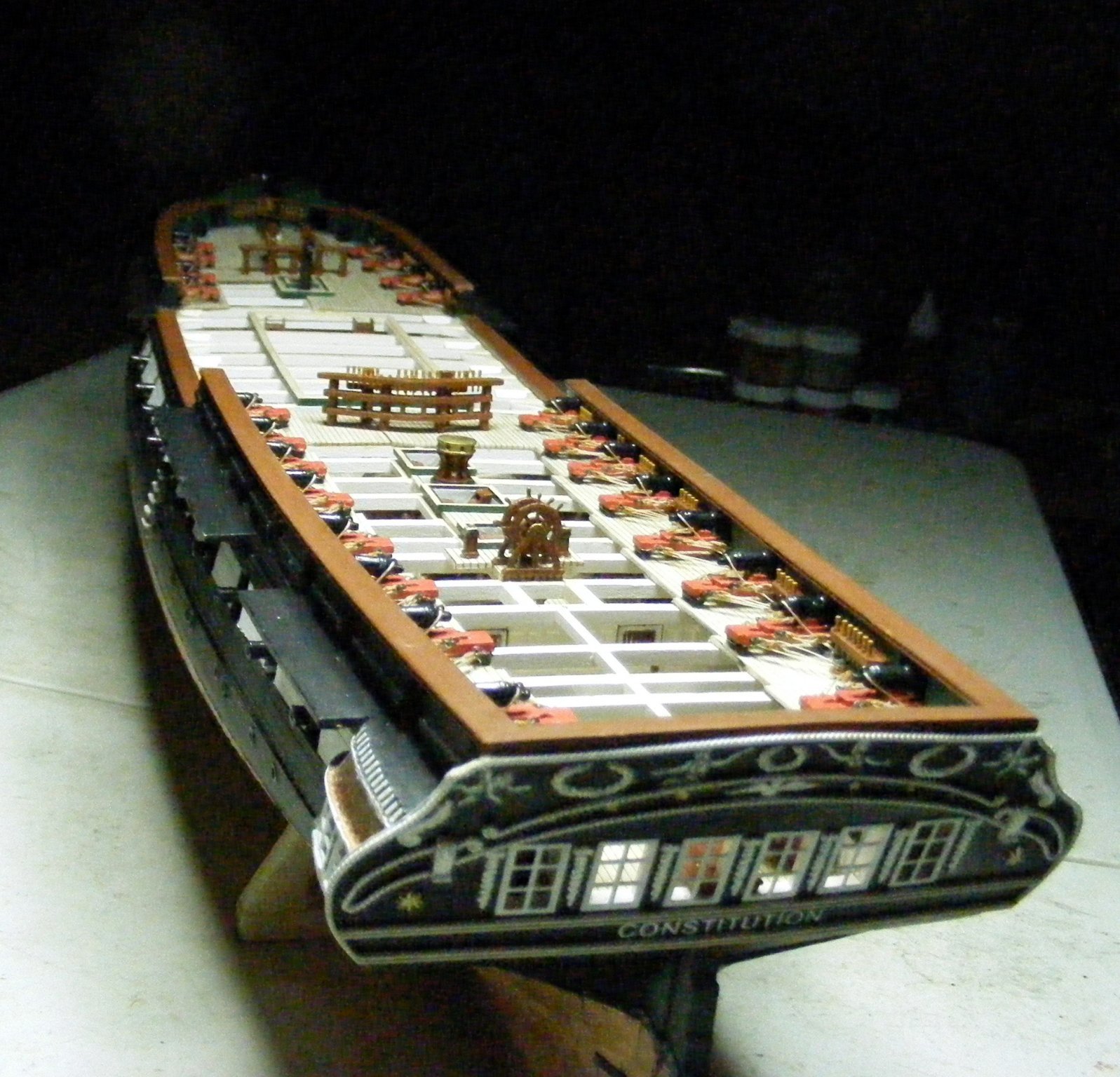
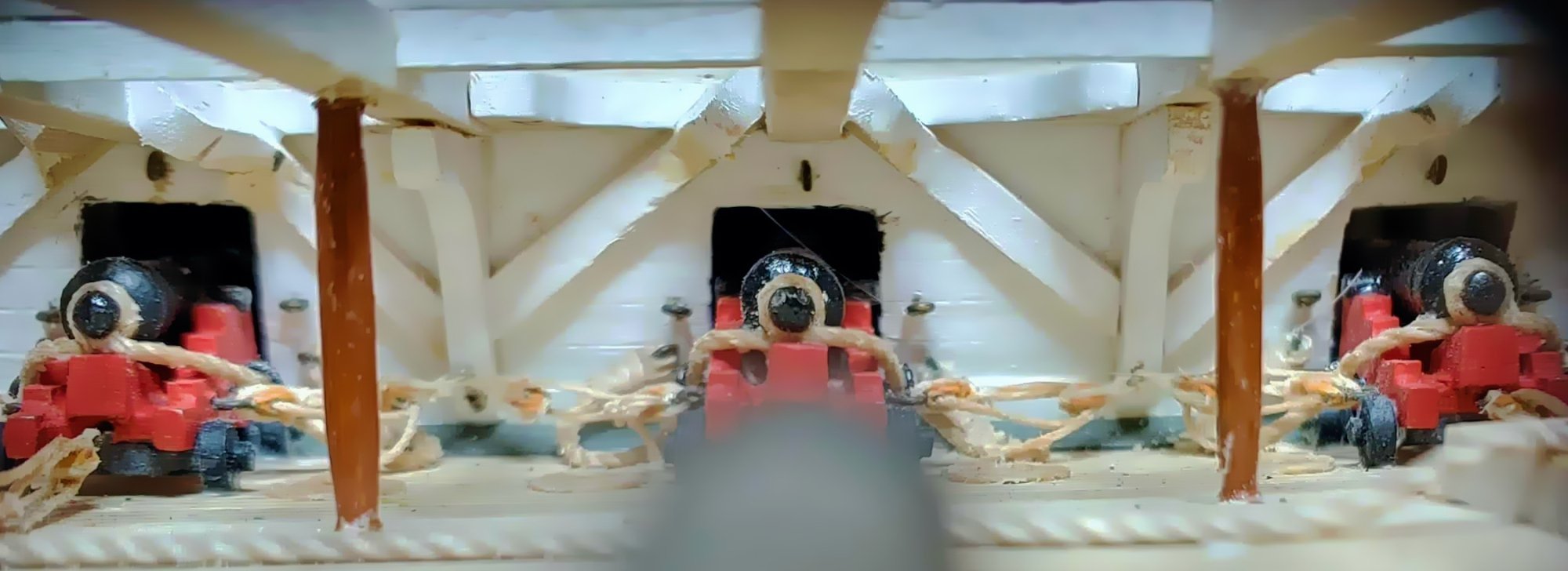
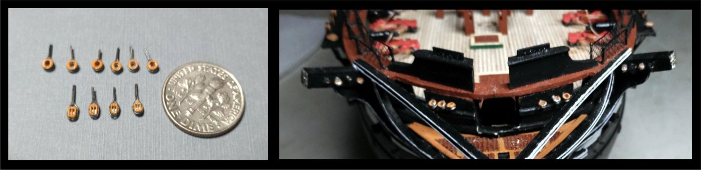
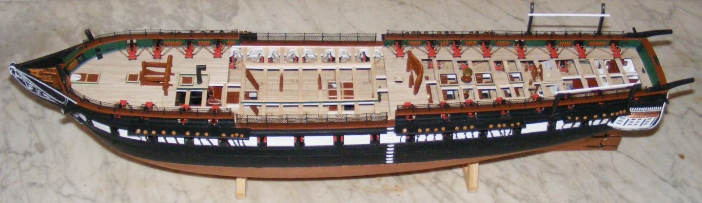
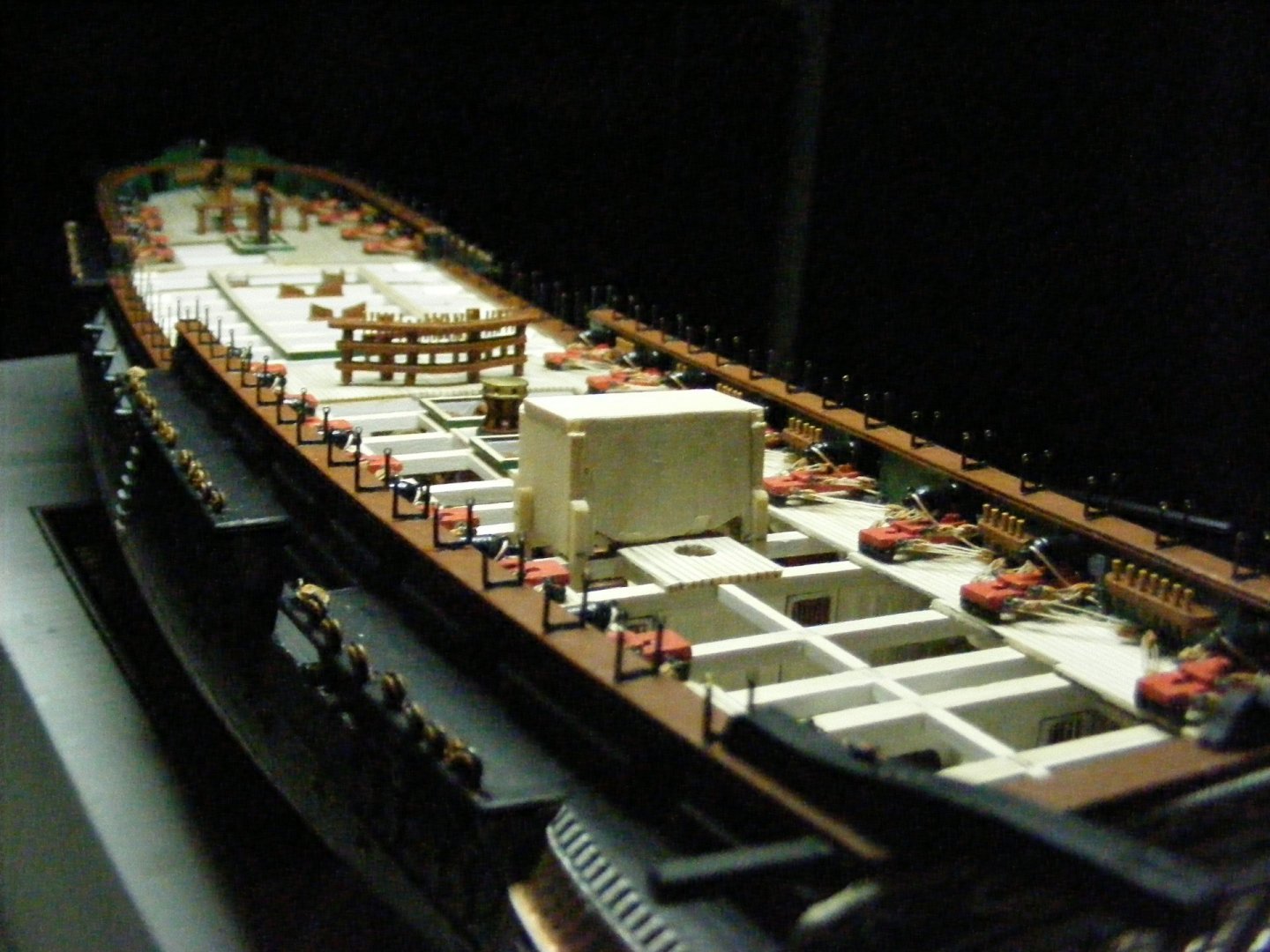
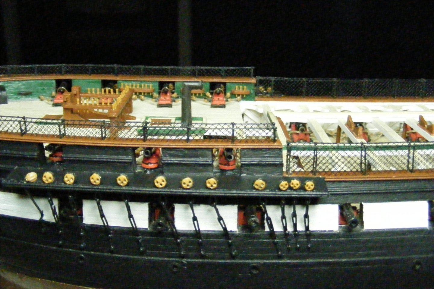
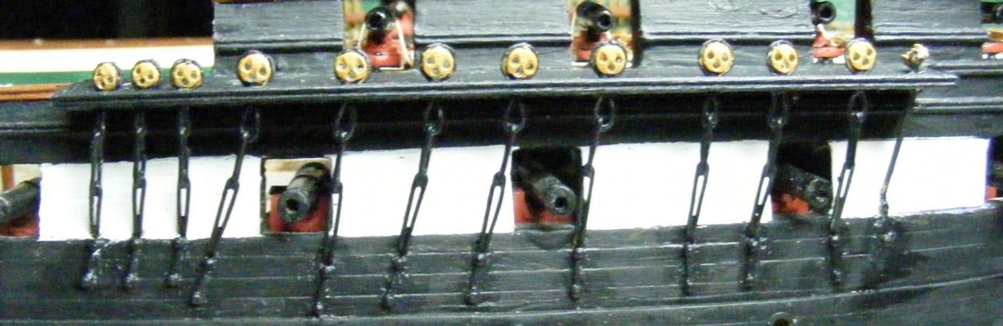
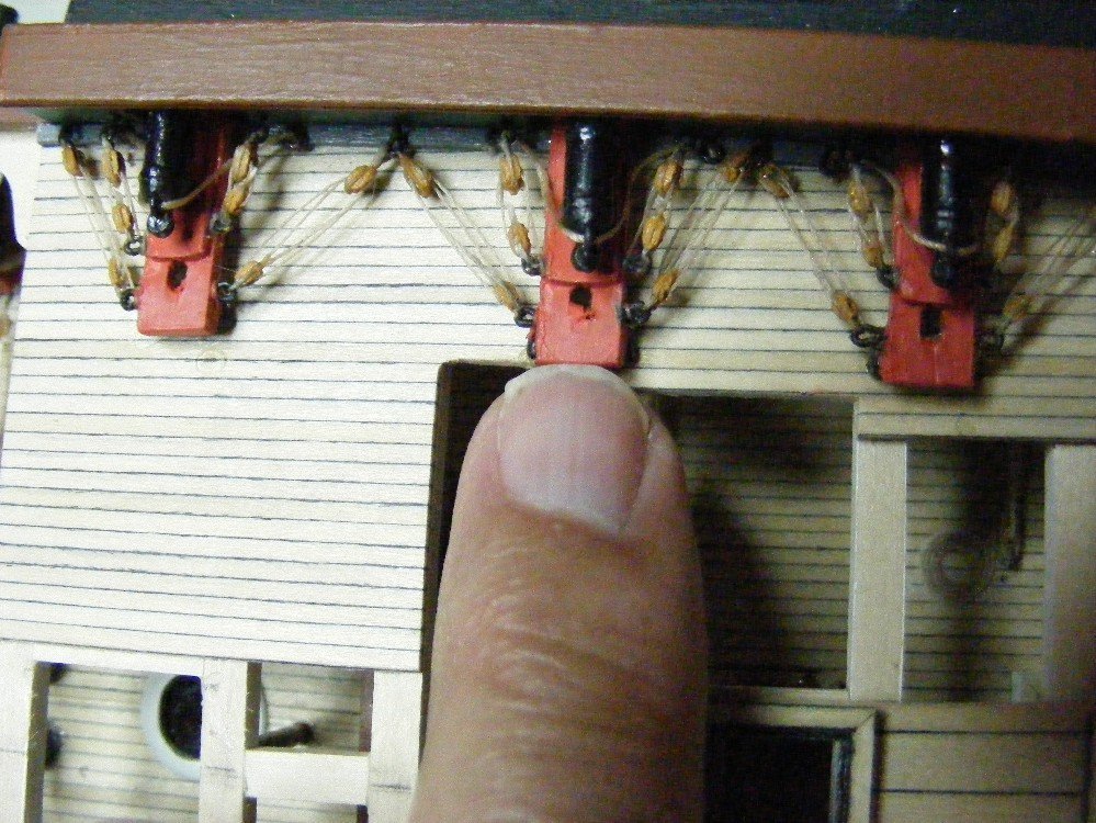
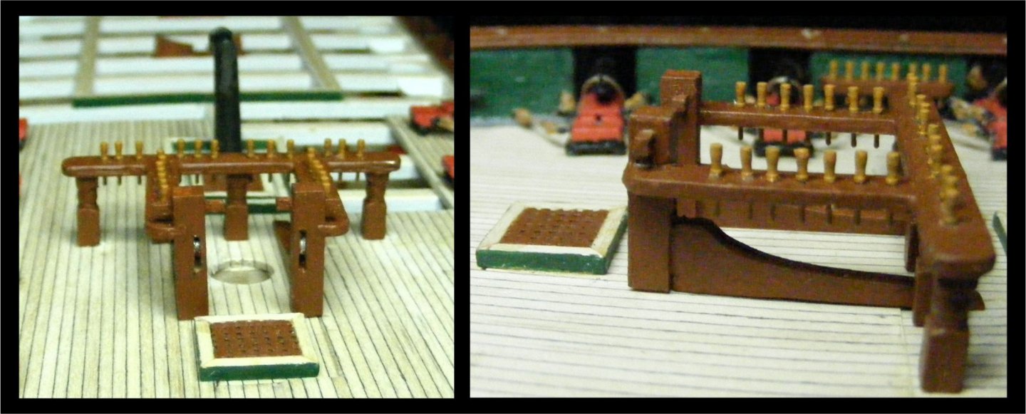
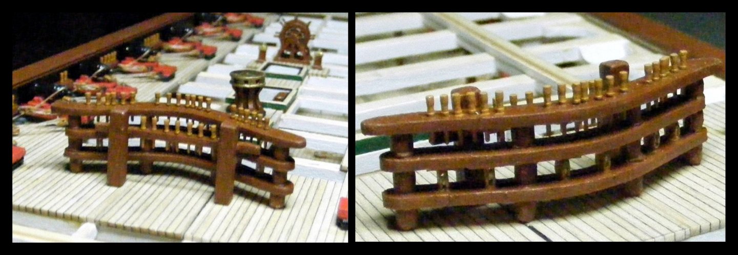
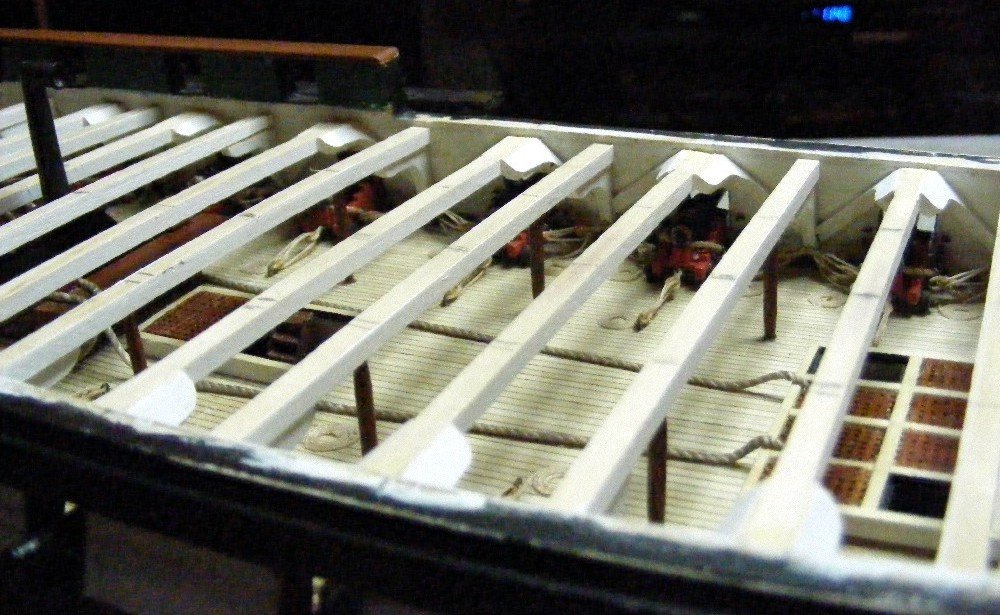
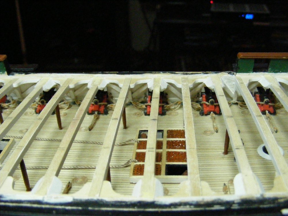
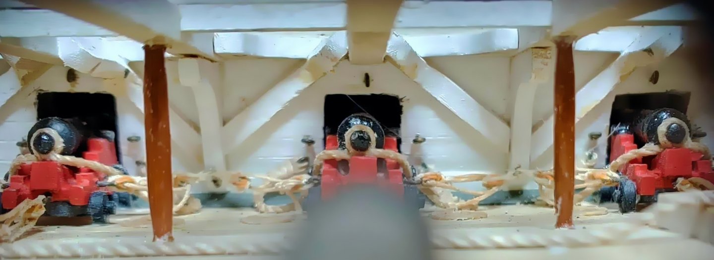
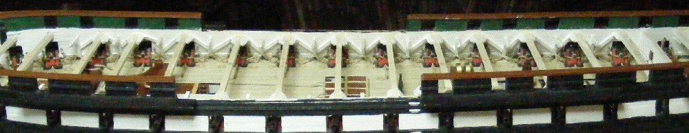
The Carronades and deck furniture The Britannia metal carronade castings are of very good quality. The barrels are easy to drill out because the muzzles are concave. The carriages and skeets are one unit. Instead of the arrangement found on the Constitution now, These guns have a lug on the bottom rather than trunnions on the sides. The elevating screw box is disc like. With sufficient skill one might drill a hole for an elevation screw. I found this task to be beyond me, so there are no elevating screws shown here. There is a breeching ring which has to be filed or drilled out to permit a line of any size to be passed through. There is extra material on the underside of the skeets just in front of the trucks which has to be filed out. Some notes on rigging which also applies to the long guns. I mentioned that the rigging fittings in this kit are all metal castings unlike most kits in which they are wood. The advantage is that they are accurately shaped, and allow the line to be rove through without popping out as they have in the past with wooden blocks. The big disadvantage is that you have to make them look like wood. In the photo in the BJ catalog, they are black - either painted or blackened. I have painted them all MS Bulwarks brown to look like wood. Also, in order for the strops to hold, CA must be used, as PVA has zero adhesion to metal. To get that adhesion, the rope or wire must be glued to the bare metal, and not the the paint or black patina, or it will not hold. I found that I have had to strop the blocks first, then paint them, which requires a very steady hand, especially with the 3/32" blocks. I have also found that using CA to glue in the ringbolts is risky, because even the gel tends to grab before I can get that little wire all the way into that little hole. I have found that a small dab of epoxy on the end of the ringbolt acts like grease when you are inserting it, then, after it sets, holds better than CA. Another disadvantage to metal blocks is that you need a file and a pair of nippers to remove excess material before they can be used. An additional problem happens only with the smallest size (3/32") The two halves of the mold are not always precisely aligned, resulting in some very strange shapes. This also happens with the 3/32" bullseyes. Back to the guns. I rigged the breeching line, the carriage tackles and the skeet tackles. I omitted the train tackles. The rigging simulates the current arrangement on the real ship. The small scale put the use of the hooks and seizings out of reach for me. Another problem, which may be my fault, is that when assembled the guns were at the same level as the caprail. They would shoot off the caprail when fired. To deal with this, I cut off the lugs from under the guns and let them sit into the lug receptacles which are molded into the carriages. The pinrails are scratch, made from 1/16" basswood strips. They are not pinned, but have strip which has a triangular cross section underneath to reinforce them. They hold up well when I pull on them. If they come loose, I will glue them back with epoxy. The provided belaying pins are turned brass and are flat on top. That shape may bothers some, but not me. They are painted MS Bulwarks Brown to contrast from the Hull Umber used on the rails The instructions call for shot lockers, but I saw no space for them, so I omitted them. Here are photos of the fore fife rail and topsail sheet bitts with knees: The rails and their stachions are metal castings. The rail has pits molded in to indicate where the holes for the pins are to be drilled. The topsail sheet bitts and knees are scratch. These bitts were made up using the layering method described above for the catheads. You can see the metal sheeves from BJ. It is dry fitted at present, and will remain so until all the standing rigging has been completed. Here are photos of the main fife rail and the monkey rail. The three rails are cast metal. stanchions that go between the three rails and between the third rail and the deck are also cast metal. Depressions are molded into the underside of the top rail, and into the upper and underside of the other two into which the stanchions should fit to make up the assembled triple rail. These are also dry fitted for now. Heads up- The above described depressions do not line up. I made the two lower rails from basswood by tracing the outline of the metal ones and cutting them out with my jigsaw. I glued them all together with rubber cement and drilled right through the lot to get holes that were lined up ready for the stanchions this worked as you can see. The fairleads between the bottom two rails are 1/8" blocks, The monkey rail posts are metal. The rail itself is scratch.in the background is the upper capstan. These capstan castings are excellent and are much simpler to install than the mini kits that most other kits provide. Here are photos of the helm and attendant binnacles. All components except the rope and drum are metal castings provided in the kit. Heads up - The handles on these wheels are extremely fragile. The slightest touch bends them, and if you try to bend them back, they break off. Getting the wheel rope to come from what appears to be a fairlead in the gun deck and through a second fairlead in the spar deck and maintain a straight line was quite a trick. The brass is Liquid Leaf Brass Here are two views of the spar deck with all its fittings:


- 110 replies
-
- 4
-
-
- Bluejacket Shipcrafters
- Constitution
- (and 2 more)
-
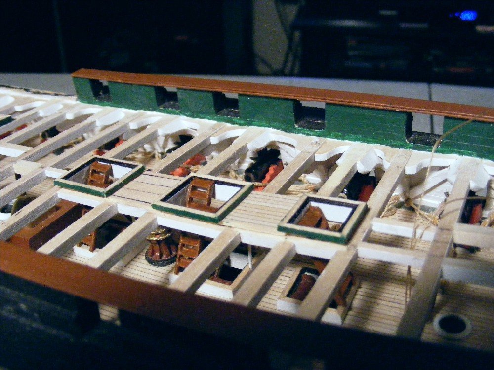
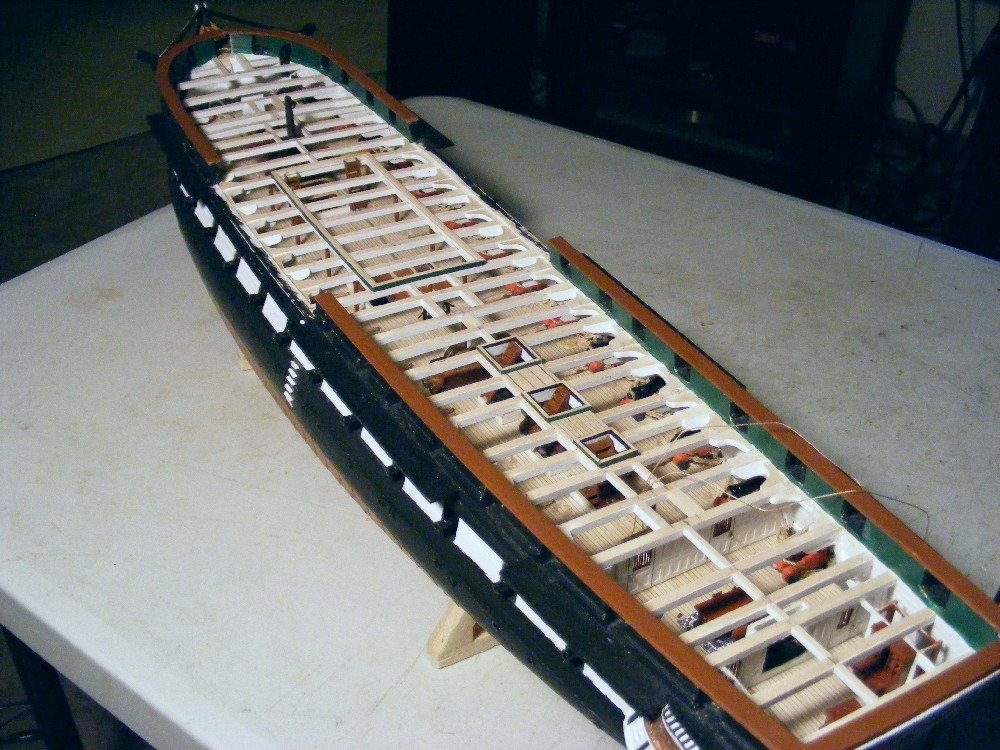
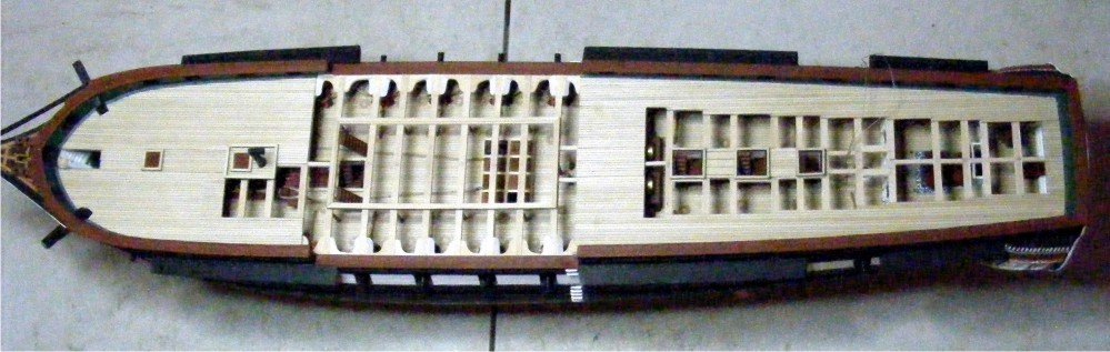
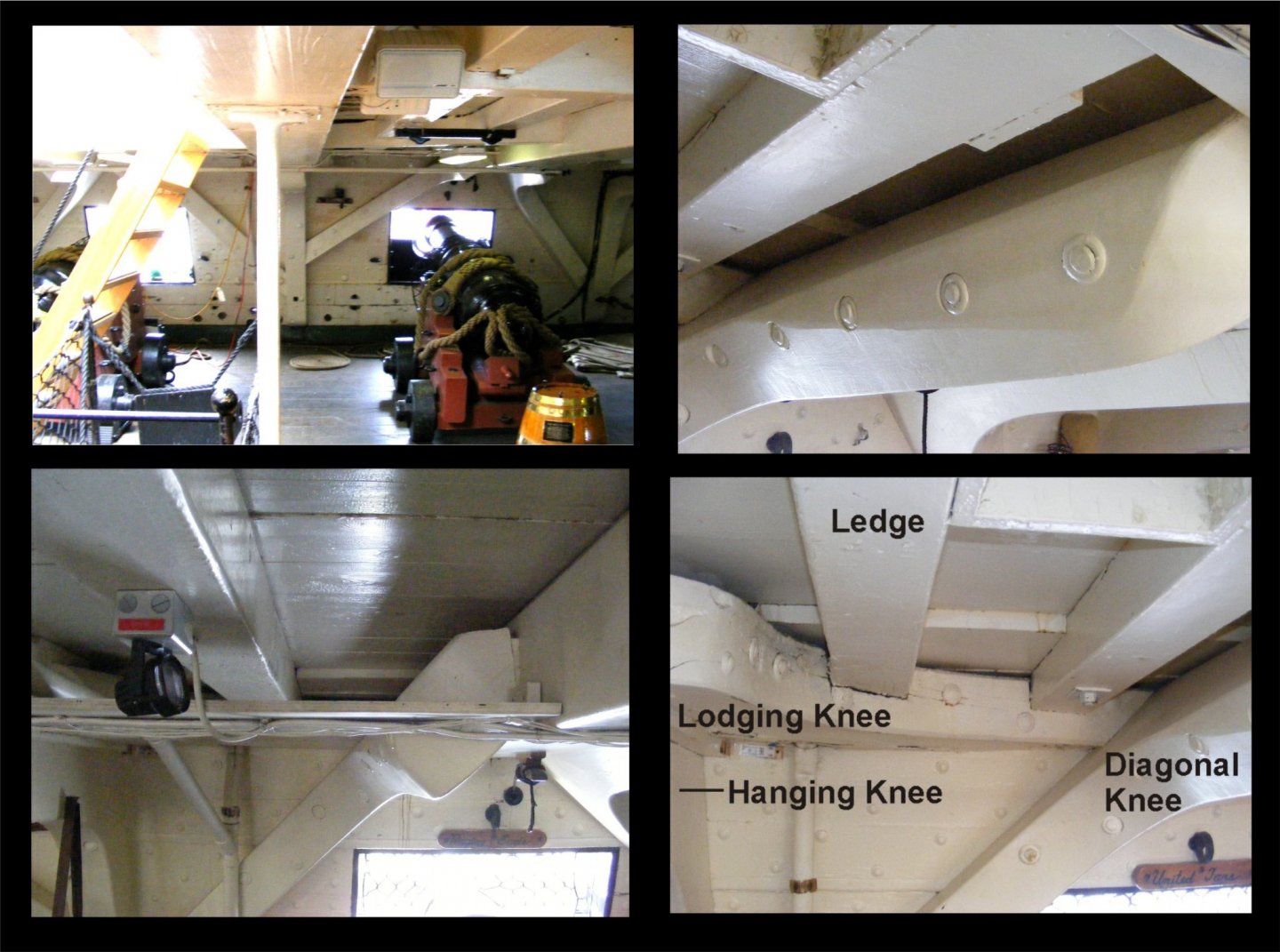
Construction of the spar deck, continued Installation of the remaining beams came next. This was relatively easy. The junction between the upper edge of the knees and the lower surface of the beam was not always perfect, but you need a dentist's mirror to see that. If I had it to do over, I would slant the upper edge of the knees upward more, then sand them down to an exact fit. The stanchions were also installed at this time. These are metal castings from the kit cut much shorter to fit the space. This next shot shows the lodging knees installed: Also visible here are the gun deck bulwark details: hanging, lodging, and diagonal knees, ceiling planking, spirketting, and waterway. Another view of the timbers with the carlings installed: Yet another view through one of the port gun ports: A shot this close reveals flaws you do not see from a normal viewing distance, but it is a novel shot. Coamings with their ladders. Again, the ladders are in once piece, and are cast metal, and painted MS Hull Umber. Just visible is one of the iron "removable" stanchions. Here is a view of the completed spar deck timbers: This model is not without its flaws, but this is where, if I may be forgiven a moment of self congratulation, i said to myself "Not bad for a rank beginner." Material for planking the spar deck is not included in the kit. I did it the same way as I did the gun deck planking - with 1/16" glued-up decking. The advantage of this is very neat caulking detail. The disadvantage is no butt joints, or tapering of the planks aft. Plank joggling at the bow is covered by the waterway on the real ship, so I am not going to worry about that either. Besides, I have neither the skill nor the tools to joggle planks which are 1/16" wide. The waist is left unplanked to reveal the knees. I am considering displaying the Pinnace beside the model so that the view of the detail I worked so hard to achieve will not be obstructed. There is only just enough planking on the quarter deck to support the deck fittings and carronades. The quarter deck knees are not completely hidden. You just have to find the right sight line to see them. Forward hatches and gratings installed.
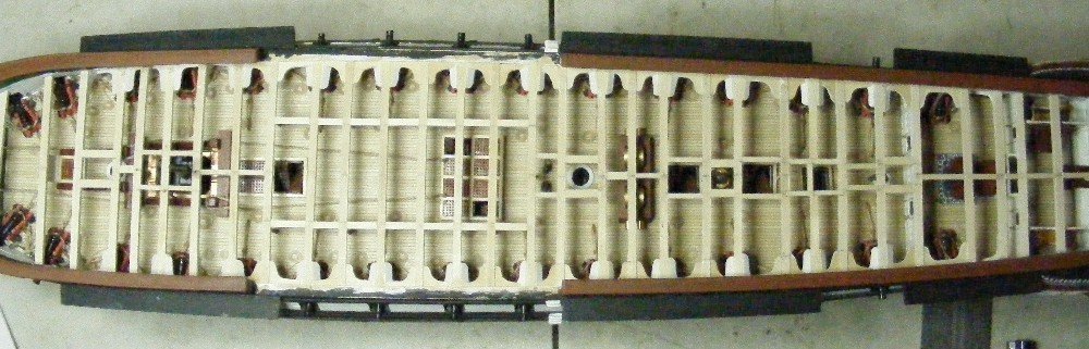
- 110 replies
-
- 7
-
-
- Bluejacket Shipcrafters
- Constitution
- (and 2 more)
-
Construction of the spar deck The instruction book has two fold out plans of the deck timbers on Constitution: one for the gun deck, and one for the spar deck. Also, I took some photos of the real ship during the refurbishing of her spar deck, hence the disarray on the gun deck.: I decided to construct all the beams, main carlings, hanging knees (already installed), the diagonal knees, and the lodging knees. I decided to omit the ledges and their diagonal carlings so that the gun deck detail would be more visible. The kit provides two basswood planks 1/4" thick which you glue edge to edge, shape the camber, then slice like bread to make the beams. This seemed unwieldy to me so I bought 5/32" by 1/8" basswood stock which matches the vertical dimension of the real beams exactly, and the horizontal dimensions almost exactly, cut them to length, soaked them in water and put them into a jig I bought from Micro Mark, here pictured bending topmast crosstree elements: As you can see, many pieces can be stacked together saving time, and insuring uniformity. Drawing a center line (better than the one pictured here) is critical to maintain a uniform camber from stem to stern. A word about the location of the gun ports. In order to pull off the timber construction, it is absolutely critical that the starboard and port gun ports be exactly opposite each other. If your hull is precisely symmetrical, you can plot their location from the bow or the stern and achieve this. However, if your hull, like mine, is not symmetrical you will need to establish a center line (I used a string with one end tied to the stem and the other hanging over the exact center (marked) of the tafffrail with a weight tied on the end), and use some kind of square to be sure that the gun ports are opposite. As you can see from the photo montage above, the diagonal knees connect to the sides of those beams that are above the gun ports. I installed these knees and beams together. Each knee is cut out individually with a jig saw to a different shape, as the angle of the bulwark changes constantly as you go forward or aft. I delayed installation of the other beams in order to give me more space to work on their tricky and critical fitting. Here is a photo of those beams and knees installed: Them's a lotta knees!
- 110 replies
-
- 3
-
-
- Bluejacket Shipcrafters
- Constitution
- (and 2 more)
-
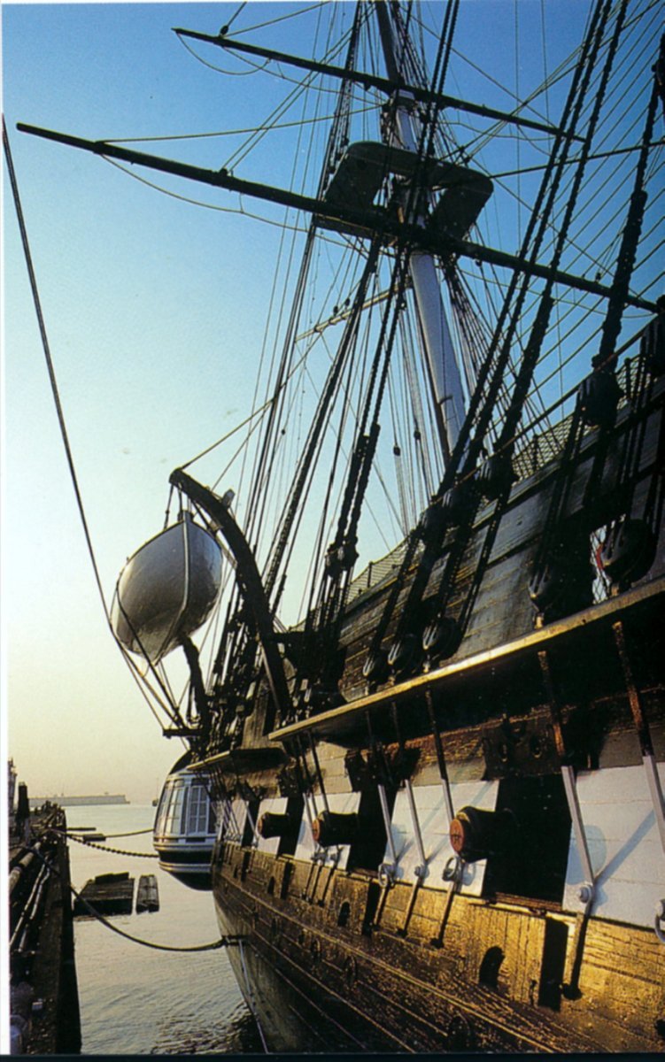
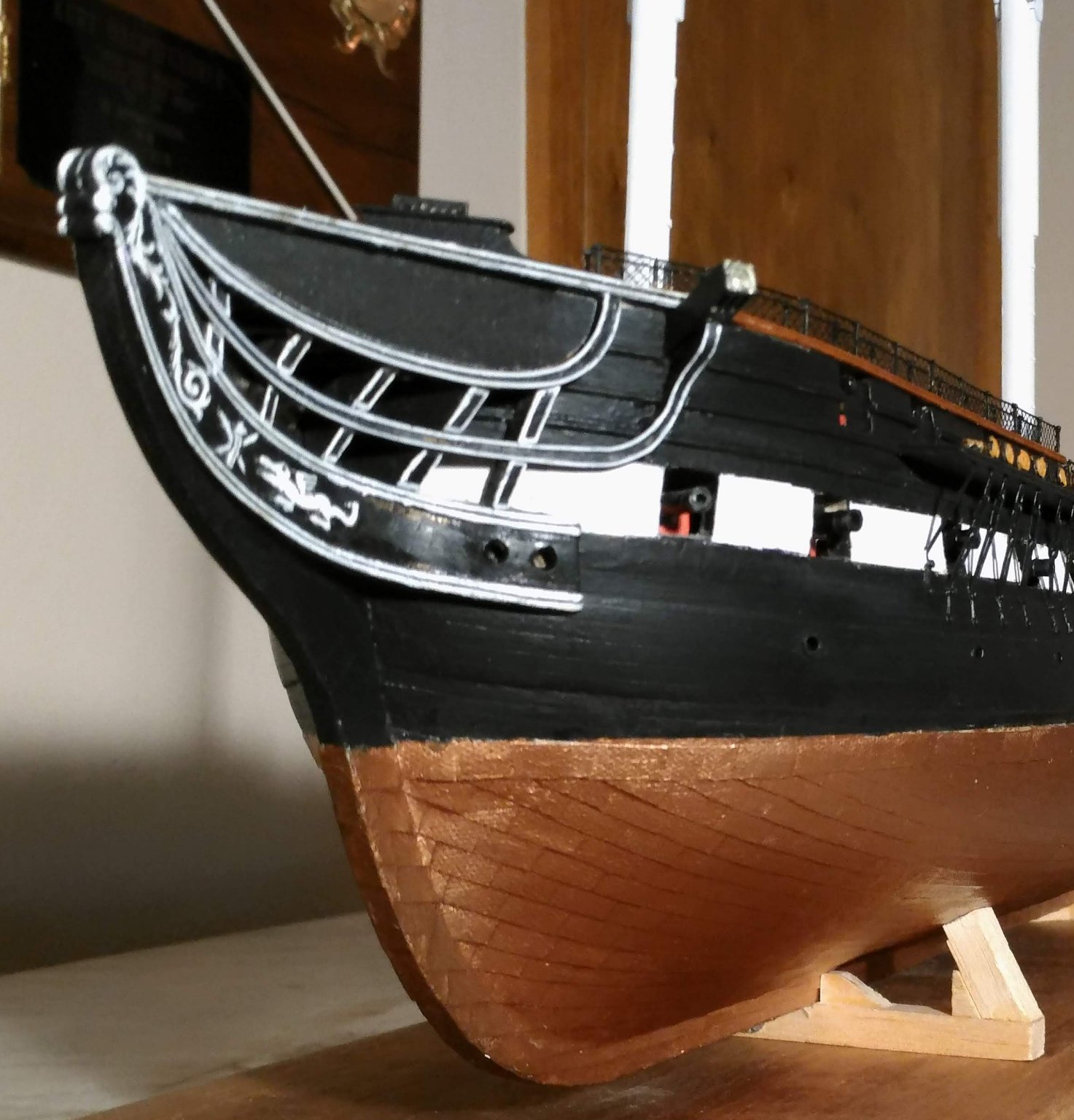
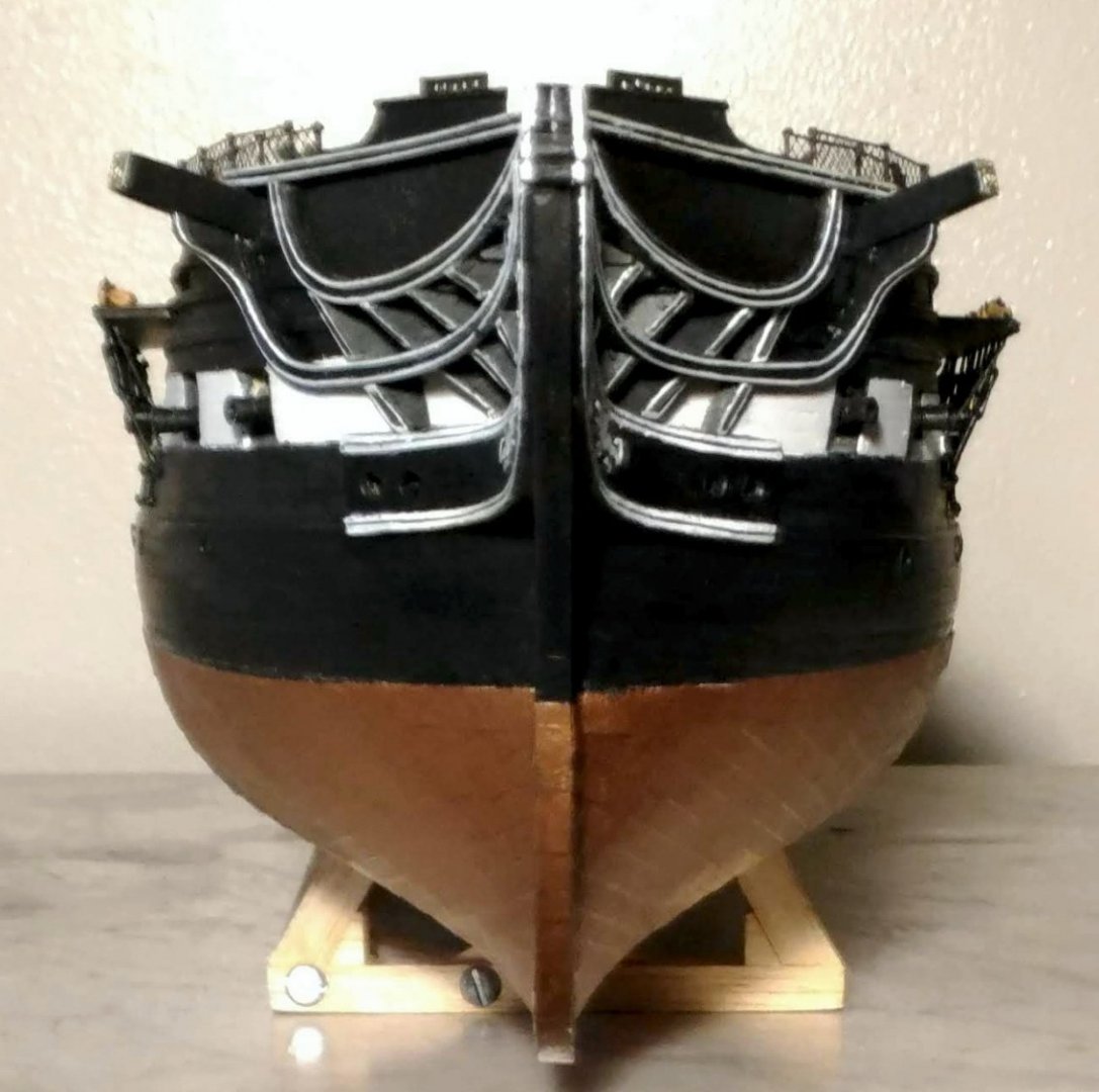
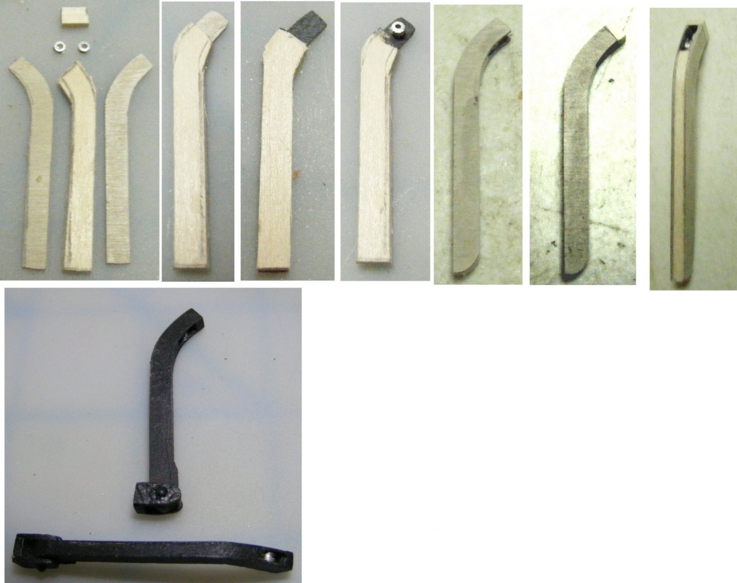
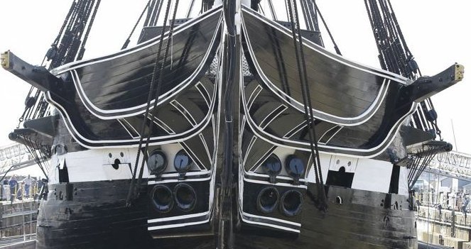
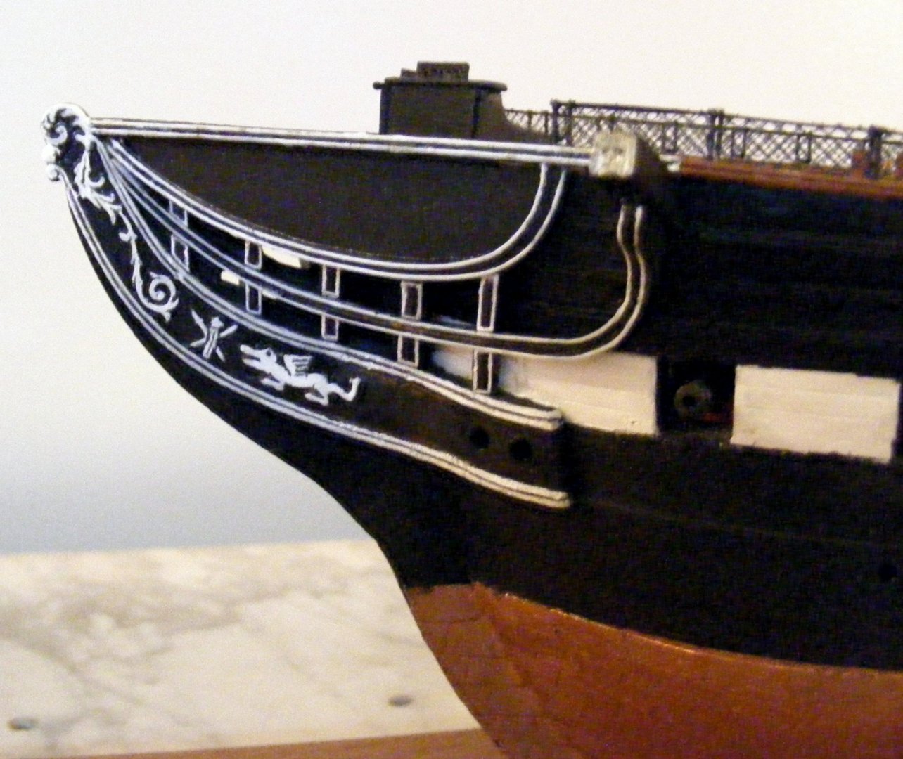
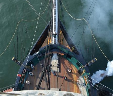
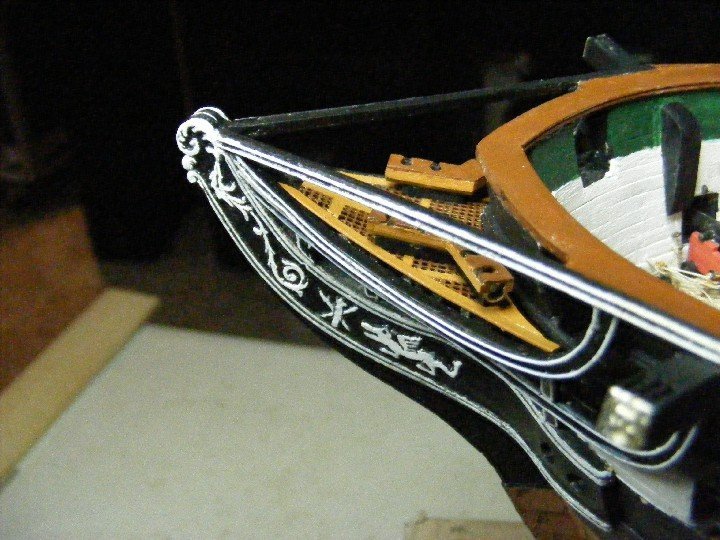
The Bow Based on my admittedly limited experience and observations, I would say that the bowheads are one of the most challenging aspects of any build. When assessing a model, the first thing I look at are the bowsheads. If they are well done, chances are that the rest of the model is as well. The plans given in the instruction book show the bowshead timbers as they currently are rather than the simpler structure shown in the Campbell plans and replicated in the Revell model which has three pairs of bowhead timbers instead of five, and a second rail which fairs into the hull without bending sideways. Drawings of the five sets of timbers appears in the instruction book on page 48. The scale is not given, but I was able to determine that they are to scale, and so can be used as is. Here is a photo of the current bowheads on Constitution: The cast Britannia metal trailboards provided in the kit are flat and need to be bent into shape. These trailboards on the ship go right to the hull and bend very sharply outwards. I did not have confidence that the metal trailboards would bend that sharply without breaking, so I used a more gentle curve, much like that in the Revell model, and used more infill (Elmer's wood filler) to close the gap. It worked well. In painting the trailboard, I tried to show as much detail taken from the Revell model as I could. The softness of the metal made bending them without distorting the details very difficult. The apparent inward curve of the false rails is an illusion. They actually curve slightly upwards. The lateral curve of the main rail is greater, and the curve of the second rail is very much greater. To have a really accurate representation, the outboard edges of the bowhead timbers must be beveled and shaped so that the top edge fairs into the inboard edge of the main rail, then curves down twisting as it goes, fairing into the outboard edge of the second rail. From there it proceeds from the inboard edge of the second rail, twisting further to allow it to fair into the outboard edge of the upper cheek. A daunting challenge indeed for a novice! To make things even harder, basswood does not always hold a sharp and stable edge. BJ has a novel, and, I think, an eminently practical way of making the rails. They provide metal sticks 3/32" square by 5" with which to make the rails. These can bend in any direction, and can be tapered nearly as easily as wood. I glued wire to their outboard edges to make the painting of white trim easier. This is what I ended up with: Obviously, this shot was taken at a later stage of the build, but it is a better photo. The bowhead grating is photo-etched brass. It was designed to fit the bow as carved at the factory. Looking straight down at the bow, the outline is semicircular. Although my hull is too sharp below the waterline, it is not too far off at the spar deck level. In fact, the forward spar deck section from the Revell model fit nicely into the space. Here is a shot of Constitution's bow taken from the fore top: As you can see, the bow is not semicircular, and the grating is a lot narrower than the one provided by BJ. I therefore cut it to shape and put in metal strips on each side: The seats of ease are photo-etched brass mounted on brass tubing sliced longitudinally. I cut these etchings down from six seats on each unit to four so that they would fit in the narrower bowshead space. Also visible are the catheads. BJ provides excellent metal castings of the carving. The cathead itself emerges from just under the caprail unlike in the plans or the Arnot model which emerge from deck level, because that's the current arrangement. If you are going to do the current arrangement, it might as well be in all respects. This allows for a more reasonable curve in the second rail up to the cathead supporting knee. The catheads were made using a layering method that I found in a download of instructions for the Caldercraft Victory: This allowed relatively neat slots into which I could insert metal sheaves from BJ. This photo shows the slots and a bit of the sheaves: It's a bit messy inside the slots, but it is better than I could have done trying to carve them out of a solid piece. For good measure, here is another more recent shot of the bowheads: The best rendering of the bowheads I have yet seen was done by Jarod Matwiy. I came across shots of his model while searching Connie models online. Superimpose it on a shot of the Boston skyline, and it could make you think it's the real thing. I would post it here, but, as I do not have permission to do that, I suspect that it would be frowned upon by the moderators. My bowheads are not on that level, but I am happy with what I did nonetheless.

- 110 replies
-
- 4
-
-
- Bluejacket Shipcrafters
- Constitution
- (and 2 more)