


KurtH
-
Posts
361 -
Joined
-
Last visited
Content Type
Profiles
Forums
Gallery
Events
Posts posted by KurtH
-
-
-
Fitting out the gun deck
The 3/32" by .020" planking used on the exterior of the hull also worked for the ceiling planking inside. A thicker plank represents the spirketting.
For the deck planking, BJ supplies enough scribed decking to do the gun deck. The plans call for 1/16" deck planks (scale 6"). Actually the real ship has planks which are 9" at the bows and which taper to 6" at the taff rail. I have seen lot of models out there which do not attempt this taper, including some museum quality ones. To see what that tapering looks like, check out photos of the real ship, or JeffT's MS Constitution build log. His tapering is perfect, all the planks being an even width at the taffrail. The plans call for 1/16", but the photos in the instruction book are definitely 3/32". I did not catch that until too late to change it. Catching things like this is where prior experience and expertise are needed. Scribed decking is used a lot in the BJ models. it is great if you are going to paint or stain the deck dark. Since I wanted to leave the deck light, I used glued up decking. It is more realistic.
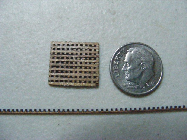
Gratings for the hatches are photo etched brass. They are close to scale but have round holes instead of square. I got cut grating pieces from Model Shipways, made from walnut.
Extra cast Britannia metal ladders that lead to lower decks were ordered from BJ. They are not visible here, but they are present.
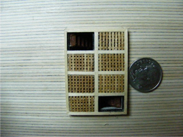
Gun deck hatch coamings and grating installed:
Hatch coamings are scratch consisting of a composite of several elements glued together, then cut with a chop saw to get mitered joints
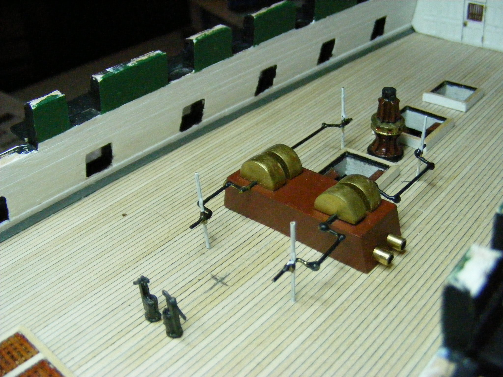
The riding bitts are scratch. The plans show length and width on the deck plan but there are no elevation drawings. I reconstructed them from drawings in the Marquardt. The manger rail is visible in the background. The camboose is an etched brass affair which folds into shape like ourigami. It was easy do do. The Charley Noble is cast Britannia metal.
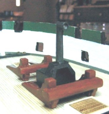
The chain pumps are also scratch, and is based on my understanding of what they look like at the time, based on drawings in the Marquardt. Again the plans give width and length and that is all. They would be very different if I did them now. Also visible are the very excellent metal castings of the lower capstan and elmtree pumps. Also visible is the waterway which I represented with a plank with its edges beveled, turned 45 degrees, and painted gray.
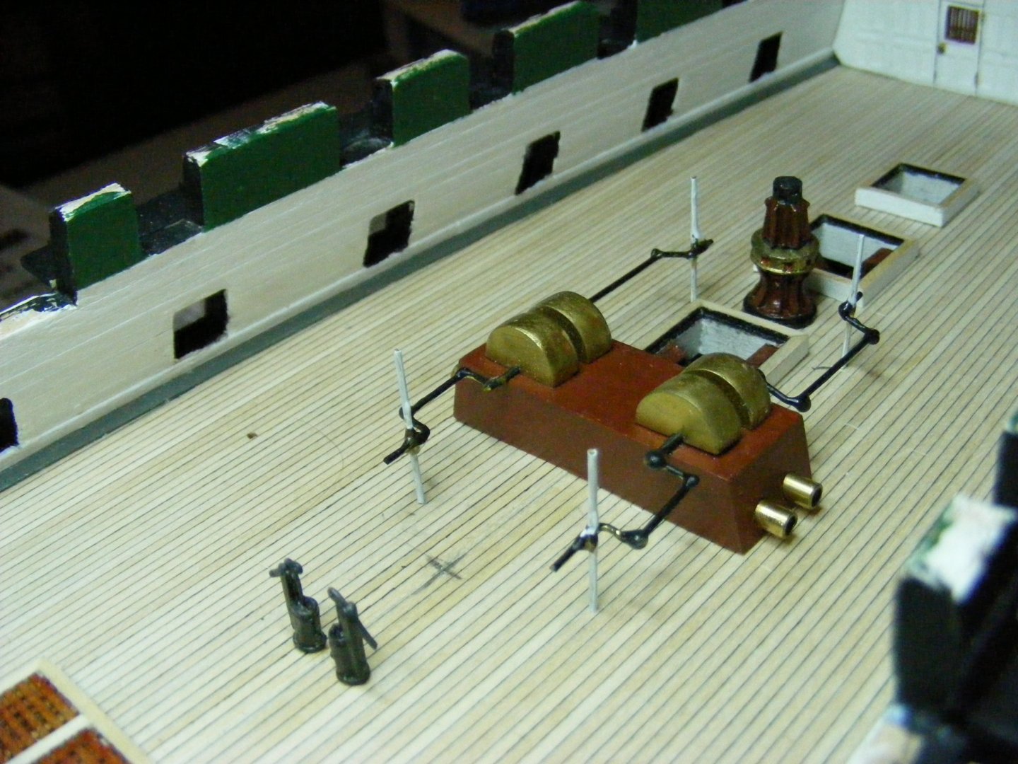
The chain pump covers and the top of the capstan are painted with Liquid Leaf Brass. I really like this product as it durable, and does not change over time. You just have to use it in a well ventilated area.
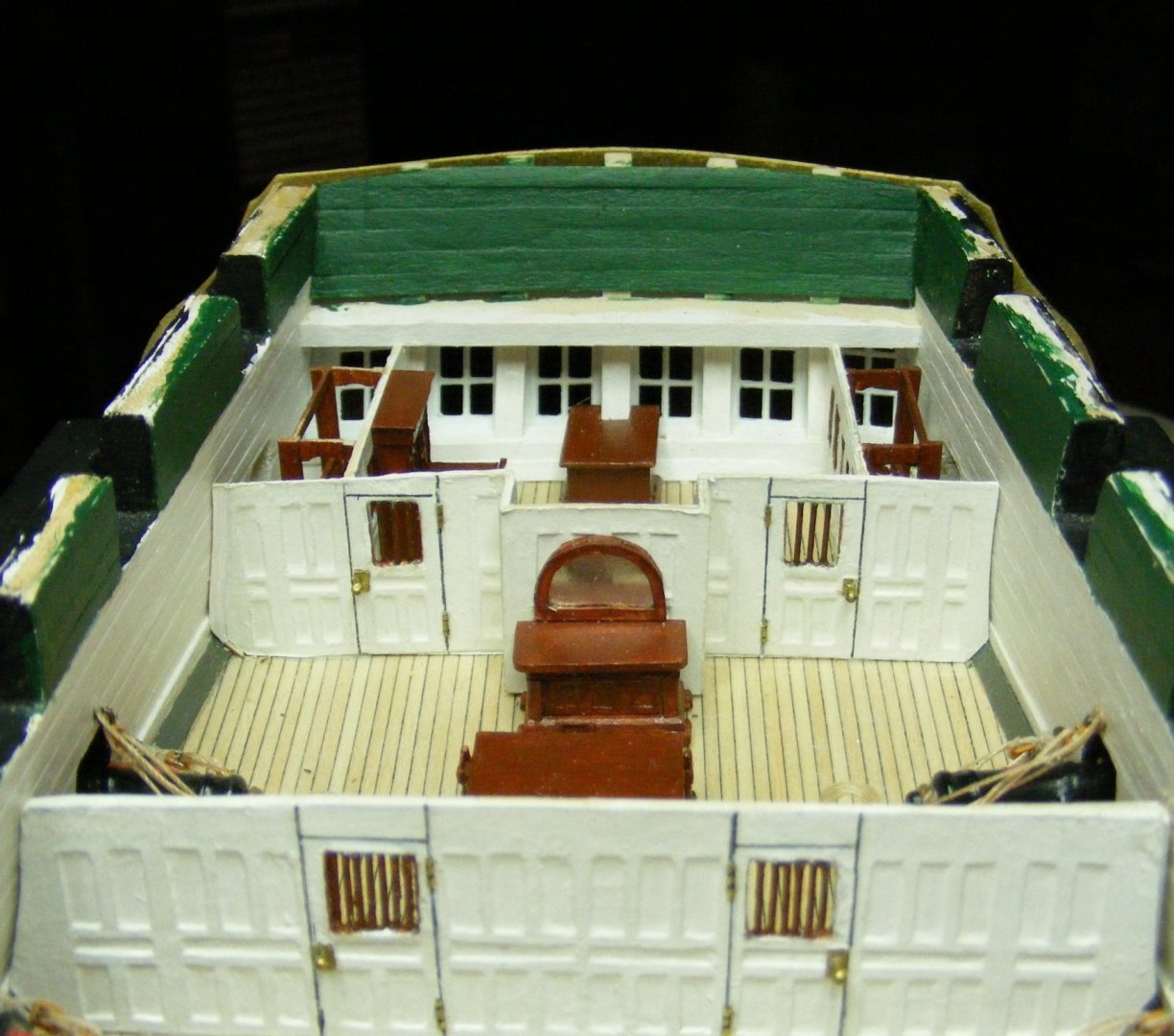
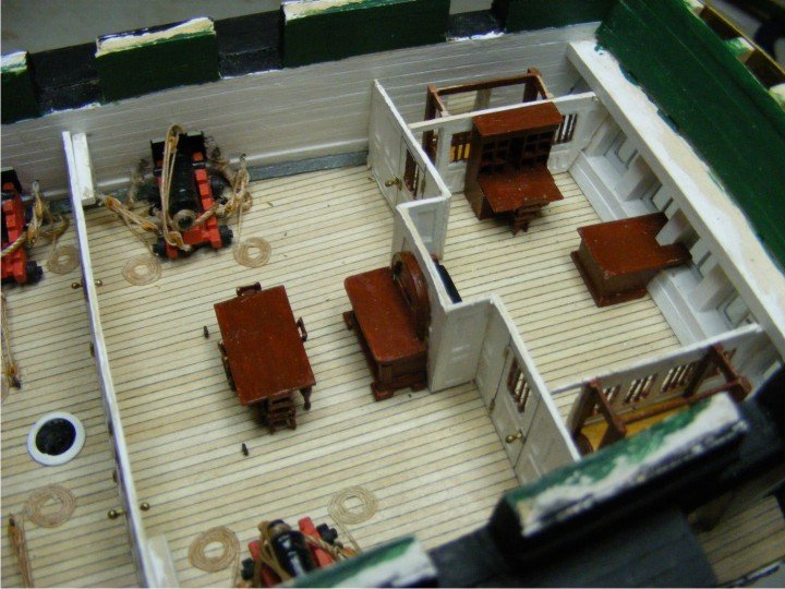
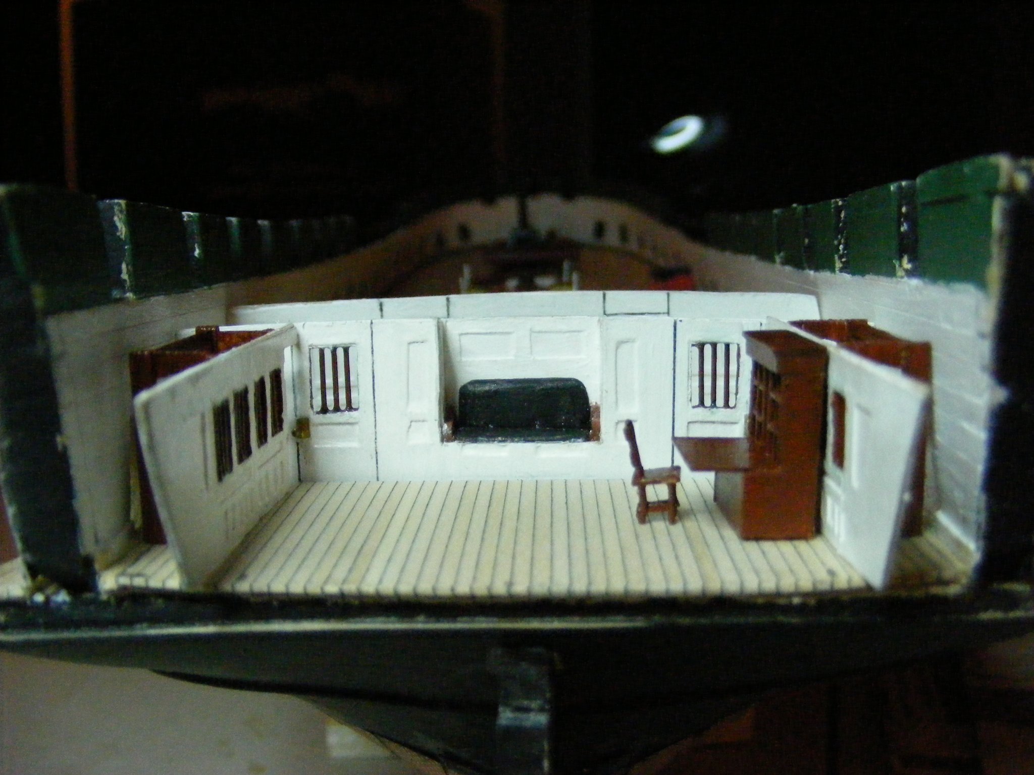
The captain's quarters are mainly guess work based on the Revell model, and the Marquardt drawings.
This is the captain's inner cabin. The bulkheads are of Bristol board with 67 lb cardstock with panels cut out overlaid on both sides. The bars in the windows and doors are brass wire painted with MS Hull Umber. The door knobs are wire with drops of CA gel on the ends and painted with Liquid Leaf Brass.

The fore and aft bulkheads are left long so that they can be cut exact size when the stern timbers are installed. Bunk beds are barely visible, which is just as well. The chair is not great, but I am happy with the way the desk turned out. It is based on a photo from that book I bought at constitution museum.
Here are some photos of the outer cabin and the finished inner cabin showing the rudder box:
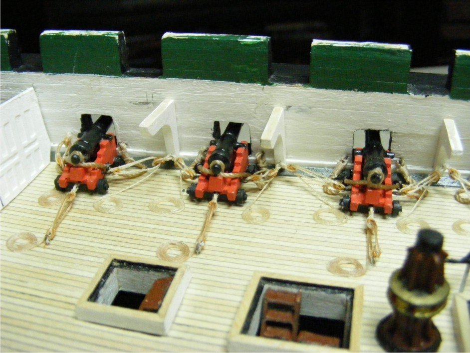
Both the guns and their carriages are Britannia metal castings. Axles and trucks come as units which look like little barbells and are glued into notches in the bottoms of the carriages. Holes need to be drilled to accommodate the eyebolts to which the blocks are attached. These castings are good, but, if you want to show the openings in the muzzles, you need to drill them out. Very hard to do with the long guns, but easy to do with the carronades, as their muzzles are concave. Another "heads up". The guns sit differently in their carriages depending on which side is up. In order to have them line up nicely, assemble one and put it in place to see if it centers well in the gun port, then place it and each gun in turn muzzle to muzzle flipping the gun over as needed.
Here is a photo of a couple of the guns in place and rigged. Blocks for rigging the guns are not included in the kit. If you want to fully rig all the guns you will need 216 3/32" single blocks and an equal number of 3/32" double blocks. Rope is MS Manila. I forget the sizes. I decided to have the side tackles attach to the hanging knees as they presently are, so I had to cut out all the hanging knees from 3/32" stock with my Proxxon jig saw and install them.
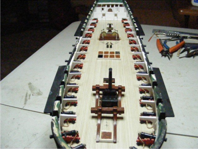
Here is a view of the completed gun deck:
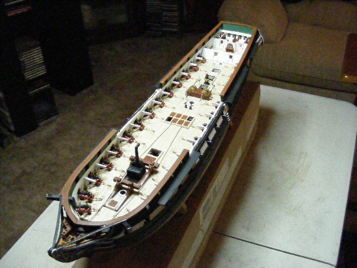
Here is another view of the gun deck with the caprails installed. I recommend drilling all the holes for the hammock cranes before installing the rails like I didn't.
-
Hull shaping, planking and coppering
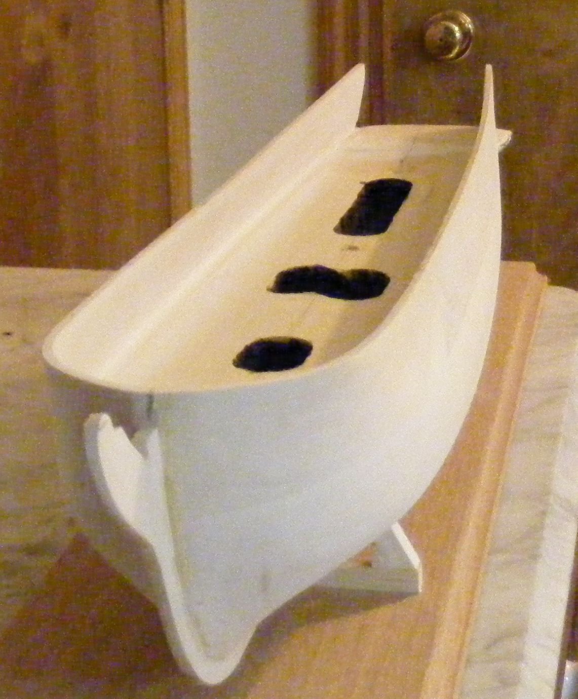
This carved hull is what I started out with:
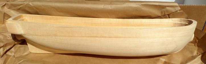
Another excellent view can be found on jfinan's BJ Constitution log.
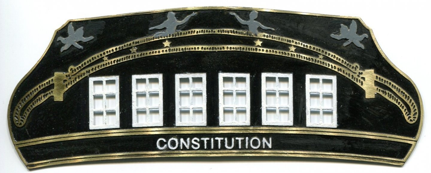
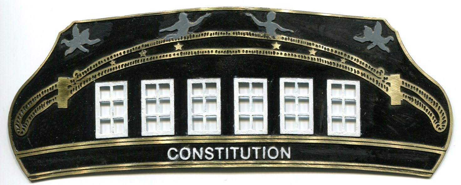
The first step is cutting out the profile of the hull using a template made from the elevation plan. Herein lies the first major pitfall. In the plan, the upper counter bearing the Constitution name cants forward. The etched brass transom fascia incorporates the upper counter as this photo of the partially painted fascia illustrates:
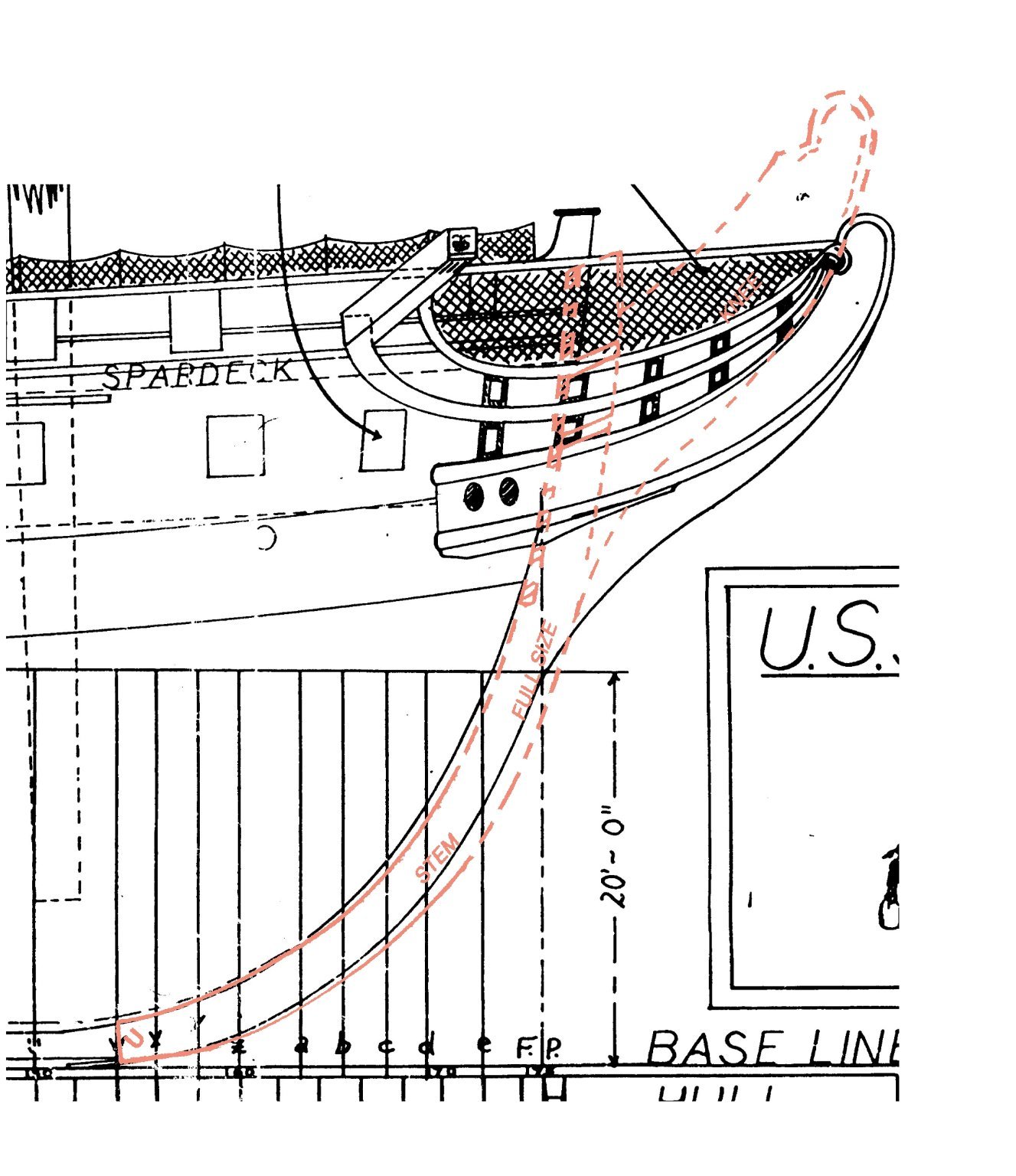
Below is a scan of the stern as shown in the plan. An edgewise view of the fascia is represented in red.
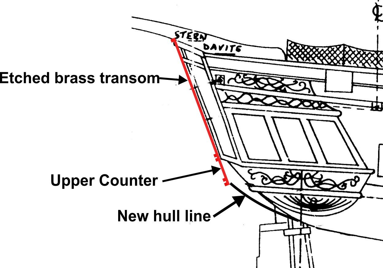
As you can see, if you cut out the stern using the provided elevation there will be empty space between the lower part of the fascia and the hull. I realized the problem too late, but perhaps other modelers can adapt the elevation to accommodate the entire fascia properly. I cut a notch in the rear of the hull and inserted a block to fill the space.
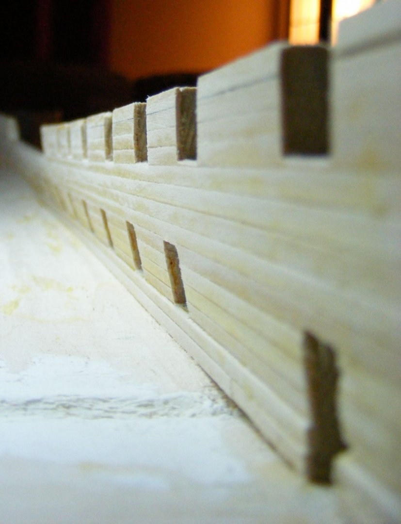
A body plan with hull section lines is provided on page 9 of the instructions. The idea is to use these to produce a series of templates to be used in the shaping of the hull. I used bristol board for this purpose. Exterior shaping should be completed before thinning of the bulwarks begins.
In installing the sternpost and stem. I recommend that the stem knee be tapered to a point as the cast Britannia trail boards are quite thick. Also, I encountered another pitfall. If the template on page 16 is used for the stem, I find that it fit the curve of the bow perfectly, but that the knee was then over 1/4" too high as illustrated in red. The top of the stem should be the same level of the spar deck, and the false rail should fair into the "shoulder" of the knee as shown on the plan.

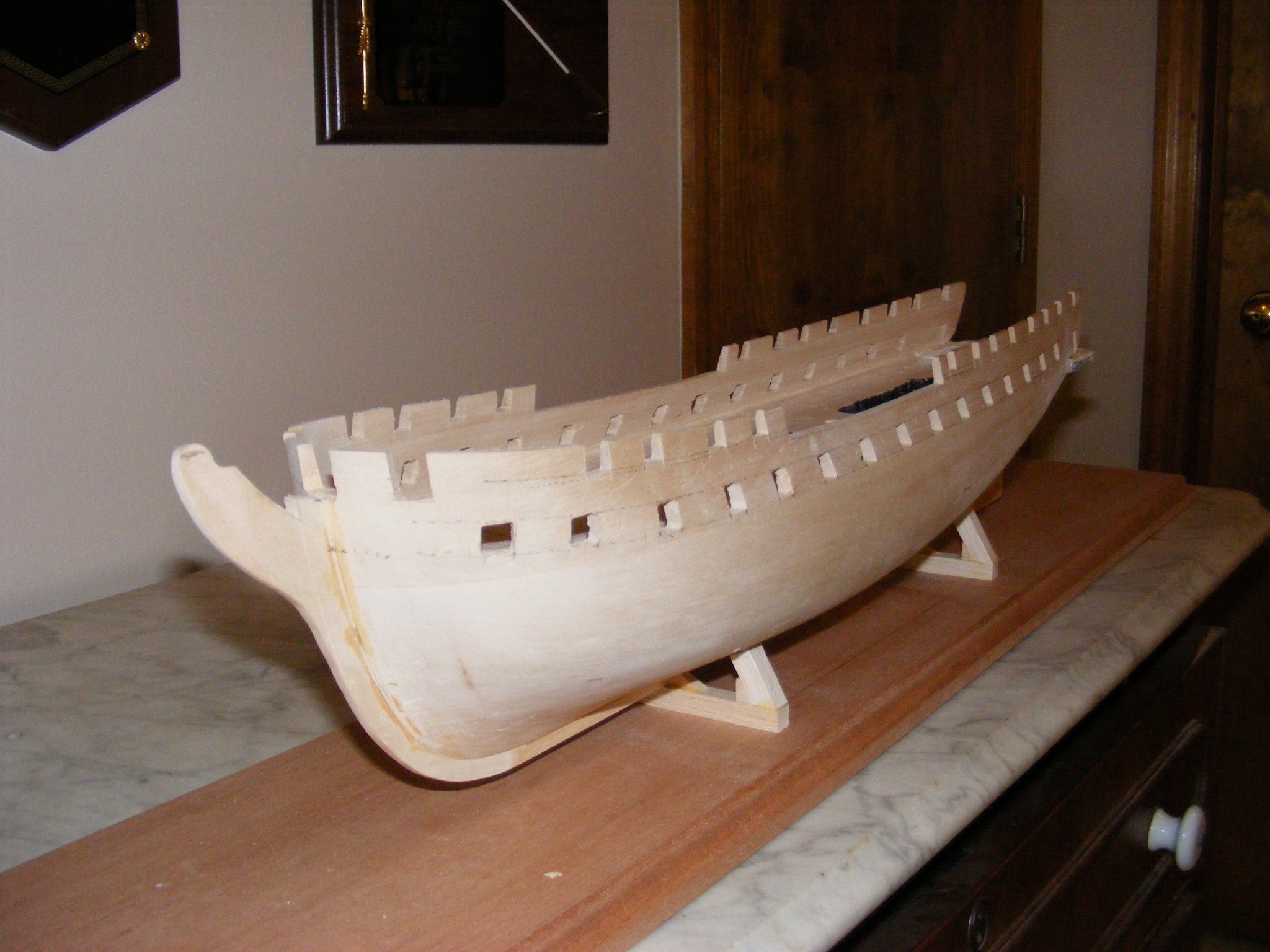
Some creative surgery was required here. I did not photograph it, and it is masked by the trailboards. Here is a photo of the hull after shaping, thinning the bulwarks, and installing the sternpost, keel, and stem knee:

I did it all with a sanding block with a rounded end. Not the best technique. The shape I ended up with looks nice, but it is not accurate, being too sharp below the waterline. I feel better, though, when I look at kit designer Larry Arnot's finished model on the cover of the instruction manual. It is not entirely accurate either, being too bluff at the bows. I hollowed out those areas in which the ladders that descend from the gun deck will be located with an auger, then I painted them black. At the stern you can just see the extra wood I inserted, You can also see that the quarter gallery carvings have been eliminated. The starboard one was a lot higher than the port one, so I just cut them off. One more thing to check before proceeding. Here is another problem that I did not catch until I went to step the masts. This carved hull twists (corkscrews) counter clockwise. Consequently, the stem and the sternpost are not in line, the sternpost leaning to starboard and the stem leaning to port. One more thing to check before proceeding. I do not know what I could have done to correct this, but I suspect that there is a master craftsman out there somewhere that could pull it off. Yet another problem which I failed to correct when shaping the hull is the asymmetry of the carved hull. This caused no end of headaches throughout the build.
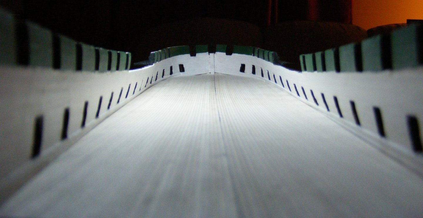
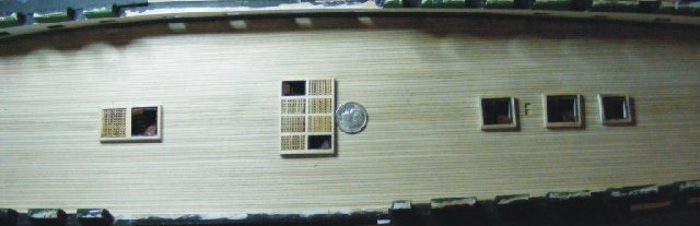
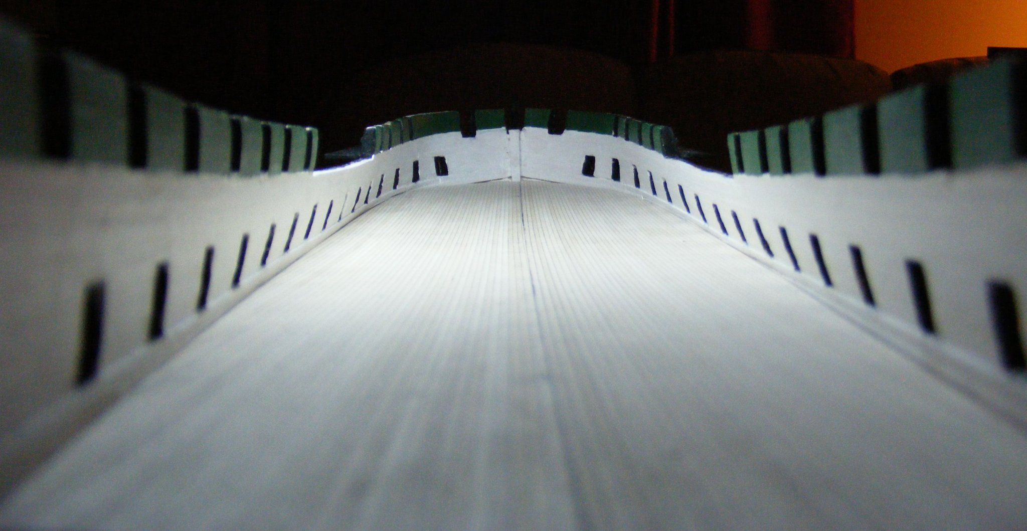
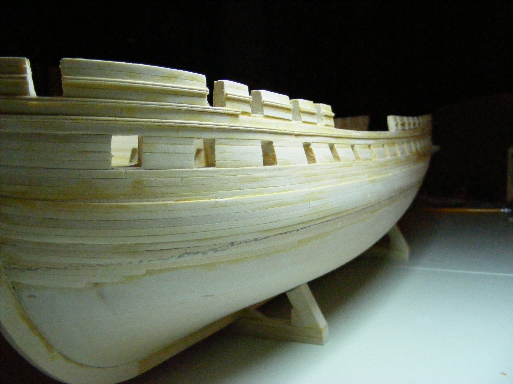
This photo shows the hull with the gunports cut:

Heads up: The spacing of the spar deck gunports in the deck plan and the elevation plan do not match. Also, I recommend that the distance between the stem and the stern be measured on both sides to be sure they match before plotting out the locations of the lower gun ports. You may want the gunports to be exactly opposite each other when the time comes to do the spar deck timbers.
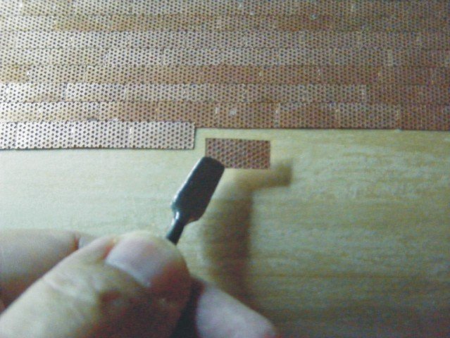
In doing the outer hull planking, I took the alternative described in the instructions of planking down to the waterline, then feathering the planks to blend with the solid hull since I planned to copper down to the keel. I have said a lot about potential problems with a solid hull, but one advantage they do have over POB and POF builds is that they are easy to plank. Doing this was a breeze, even for this novice. I followed the planking patterns shown in the Revell model and came up with this:

The planks needed to do the job are not included in the kit. Planking stock is available from BJ. Basswood 3/32" by 34" by .020" thick
is ideal for hull planking. I also ordered other sizes and thicknesses to make the thicker wales. Double bead strips from BJ are also used.
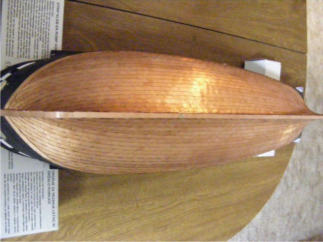
If you want to copper her bottom, plates are available from BJ. They are not included with the kit, and do add significantly to the cost. They are copper plated Britannia metal, with a great deal of nail head detail and come on a sprue:
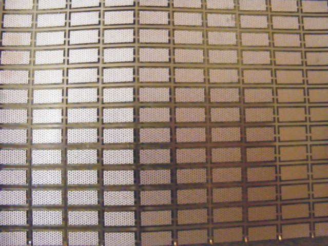
I applied them according the the instructions, overlapping upper over lower, and fore over aft. The hull is inverted in this picture. Right is forward.
I followed the layout shown in the Revell model and the Marquardt AOS with a single dressing strake at the water line and a few stealer strakes aft.
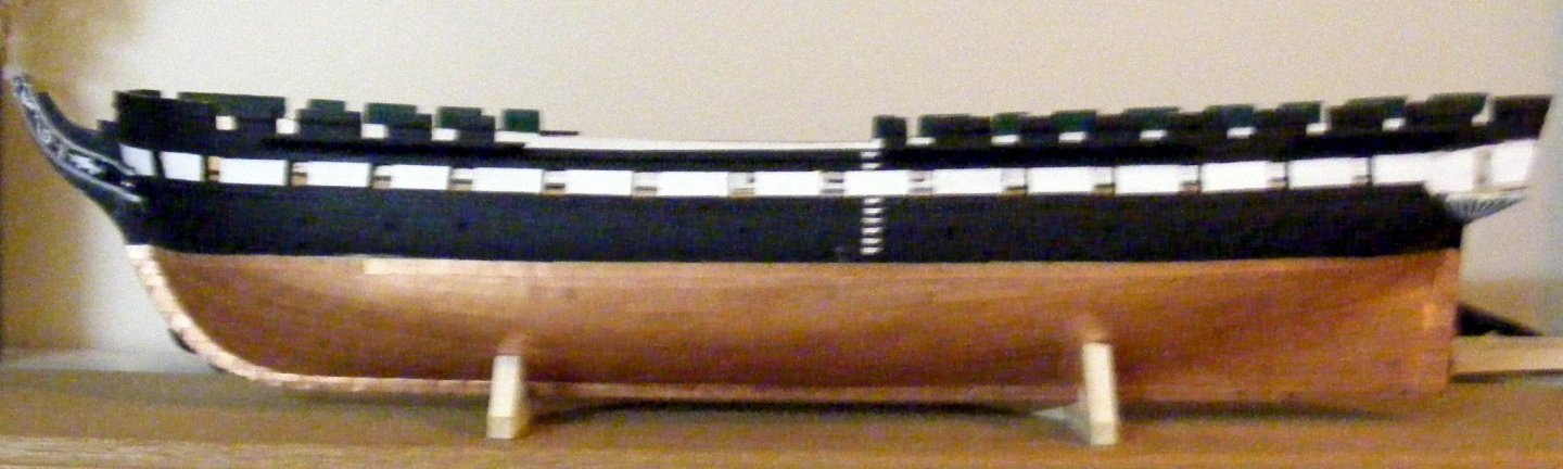
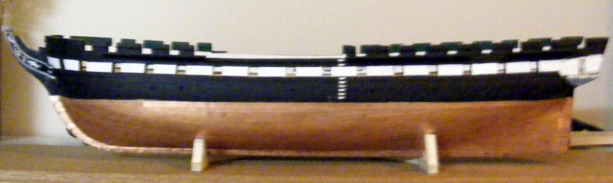
This photo shows the outer hull painted, coppered, and with gangway steps, trailboards (more on those later), and lower quarter gallery finishing pieces installed:
-
Introduction
When still a teenager, I did some plastic ship builds, but stopped when my music teaching career began, as there was no time for such pursuits. After retiring, my daughter Kris suggested that I take it up again. Feeling very ambitious, I decided to graduate to a wooden ship build, and chose the BJ Connie because it was the only one designed to allow the complete fitting out of the gun deck. The blurb in BJs catalog makes clear that this is a very challenging build, designed for experienced craftsmen. I assumed that this referred to the requirement that many items were to me made from scratch and decided to forge ahead.
The BJ Connie is a solid hull kit. There are no laser cut wooden parts here. There are a huge number of Britannia metal parts, including all the rigging fittings. The boats are resin castings which include rib and keelson details and, in the case of the gigs, flooring detail. A wide assortment of rigging line is provided - black for standing and white for running rigging. Etched brass is provided for the transom, gratings, hammock crane irons, chain plates, etc.
The folks at BJ are accessible, supportive, cooperative, and pleasant to work with, so I imagine that they would provide a parts list if you request it.
There are four sheets of plans, and a 123 page instruction book. These provide a great deal of information, but not nearly enough to guide the novice to a complete and successful build. I found the Karlheinz Marquardt "Anatomy of the Ship USS Constituion" book to be indispensable. I also bought the Revell plastic model to use as a reference. This model is also scaled at 1/96, so the builder has a choice between using the Britannia metal parts or plastic ones.
I also used a book of photos of the ship: "USS Constituion, Old Ironsides" Photogaphy by Steve Dunwell, Fort Chruch Publishers, 1991 which I bought at the USS Constitution Museum.
This log is from the perspective of a novice, so there not a lot of advanced techniques to be found here. However, I do provide a number of "heads up" alerts regarding things like misleading and contradictory information which do occur, which may help even an expert save time, as well as lessons learned from making mistakes.
- ubjs, Duanelaker and Bill Morrison
-
 3
3
-
I have just accidentally deleted my entire build log. I thought I was deleting one post rather than the whole thing. I must now redo the entire log. This is most distressing, but at least I have the opportunity to make improvements in what I did. Fortunately I still have all the photos that I used. Unfortunately, all the likes, comments, and photos that were posted to my log by other MSW members are lost. Work on this will commence this afternoon. Unless the moderators object, I will do a series of posts, rather than try to do the whole thing in one. I plan for each post to be on a particular topic, or phase of construction.
-
A superb model. Congrats!
-
Looks like you are good to go.
-
Heads up. The locations and measurements of the spar deck gunports for carronades shown on the elevation and on the deck plan do not match. Not realizing this, I went from one to the other as I was marking out the ports. As a result mine are in the wrong places. Also check to see if your hull is exactly symmetrical. If, like mine, it is not, the gunports on the starboard and port sides will not be opposite each other. That can wreak havoc when you install the spar deck beams. I recommend that you measure the distance between the stern and the stem on both sides to be sure they match if you have not done so already. I found I had to leave the hull asymmetrical, so as to avoid sanding through the starboard gunwales completely.
-
Nice smooth looking hull shape. Page 75 of the Marquardt AOS has cross section views which give a good idea as to how the frames are tapered. Also, looking at the bulkheads on the Connie by MS builds can give a clue as well.
-
-
-
If you go to the home page and enter "Bluejacket Constitution" in the search field, all the Bluejacket Constitution build logs should come up. Unfortunately, I did all that years before I even knew about MSW, so I am not all that specific on exactly how I did it. As I recall, I was stumbling along in the dark and hoping for the best, not having had any prior experience. I do recall making mockups of the transom fascia, and the the upper finishes and window pieces for the quarter galleries out of Bristol board and experimenting with them before attempting to actually assemble the stern. That is how I discovered the problem with the stern profile that I described at the beginning of my build log.
-
I am following your progress with considerable interest. In looking at the various builds of the BJ Constituion, I am fascinated by the resourcefulness, inventiveness and creativity I see in the solutions to this thorny problem. It looks like there are as many solutions as there are builds. All the best.
Kurt
-
Very neat job on that gammoning. Well done!
- jfinan and mort stoll
-
2
-
I say, go for it. My build log shows a gazillion and one mistakes.
- mtaylor, Canute and Landlubber Mike
-
3
-
-
-
-
-
I have installed all the shroud pairs on the mast heads and am about to install deadeyes at their ends and rig the lanyards. Is there a tried and true method for preventing the deadeye from rotating horizontally as the shroud is tightened, or does one depend on the sheer pole to control that?
-
-
Excellent work. I saw a full replica of that vessel tied up at the marina in Poughkeepsie some years back.
-
-


USS Constitution by KurtH - FINISHED - BlueJacket Shipcrafters - 1/96 - First wood model kit
in - Kit build logs for subjects built from 1751 - 1800
Posted · Edited by KHauptfuehrer
The Stern: rudder, quarter galleries, and transom
Heads up: The provided gudgeons and pintles measure 1/8" as the interior dimension.
The stern post, like the keel is made from 3/16" stock. If you taper the stern post to 1/8", it will fit. You would then make the rudder from 1/8" stock to match. Otherwise, adapting the provided gudgeons and pintles to the 3/16" size is very awkward. I ordered 1/4" size gudgeons and pintles from BJ. These were easily adapted, as the metal is soft and pliable.
Here is a photo of the rudder in place. The simulated bolt heads are drops of glue. Also visible are the afore mentioned stealer strakes in the coppering:
I have found the building of the quarter galleries and their integration into the hull shape and transom design to be a remarkably troublesome process. I see four reasons for this. The first is my own inexperience and undeveloped skills. The second is the misleading first step detailed above. The third is that the castings which make up the quarter galleries are well out of scale. The fourth is that these components bear little resemblance to the plans. Solutions to these problems requires a degree of creativity,ingenuity, and resourcefulness that I could not have imagined when I started this build. It is fascinating to see the variety of creative solutions found in the other build logs of this kit. I found that making up Bristol board mockups of the transom, the upper finishes of the quarter galleries, and the window panels, and experimenting with them was a critical step to a solution.
The first step was making up the stern timbers:
This looks a bit crude, but the vertical timbers are accurate and interface well with the bulkheads in the cabin and the windows in the transom fascia. I made sure that the lower edge matches the camber of the transom. The floors of the quarter galleries are shaped from that block of wood I inserted to fill the gap described above. They look nothing like the plans, but they did work out in the end. The stern was then ready for the transom.
The brass photo-etched transom is a single piece. The design is unique and incorporates elements of both the a contemporary illustration of her launch and the Hull model:
The nereids and human figures are flat and featureless, and do not have castings to make them 3 dimensional. They require either some very skilled work with sculpey, or similar product, or painting and shading with detail added with a fine pen. I chose the latter option. There are, however, excellent castings of wreathes, scrolls, pendants, eagle, and two large stars that can be applied. The instructions call for rope detail made from twisted wire around the perimeter. As you can see, there is rope detail etched into the fascia, which I do not like. I ordered twisted wire of a suitable gauge (I do not remember the gauge number) from a jewelers supply site which I used around the perimeter and over the etched rope detail. I also overlaid the double strips outlining the upper counter with double bead strip from BJ, and ended up with this:
Barely visible are the edges of the lower gallery finishes (stools) which are canted inboard to integrate them into the hull shape. I decided to leave the windows unglazed to make the cabin within more visible.
The quarter galleries were the next challenge. Four metal castings are provided: the roof, the window panel, the upper finish, and the lower finish (already installed). The window panel and the upper finish are flat and need trimming and shaping. Feeling ambitious, I decided to file out all the window panes and glaze them. The roof section was way too long, so I cut quite a bit off the aft end. The experimenting I did with the mockups was critical in integrating them all together with the transom.
Here are two views of my solution to the stern challenges:
I had to sacrifice the aft most gun port to accommodate the gallery, but overall, I am happy with how it came out.
I took a shot of the quarter gallery compared to the one on the Revell model to show the difference in scale between the two:
My apologies for the bad focus, but you get the idea.