


John Gummersall
-
Posts
232 -
Joined
-
Last visited
Content Type
Profiles
Forums
Gallery
Events
Posts posted by John Gummersall
-
-
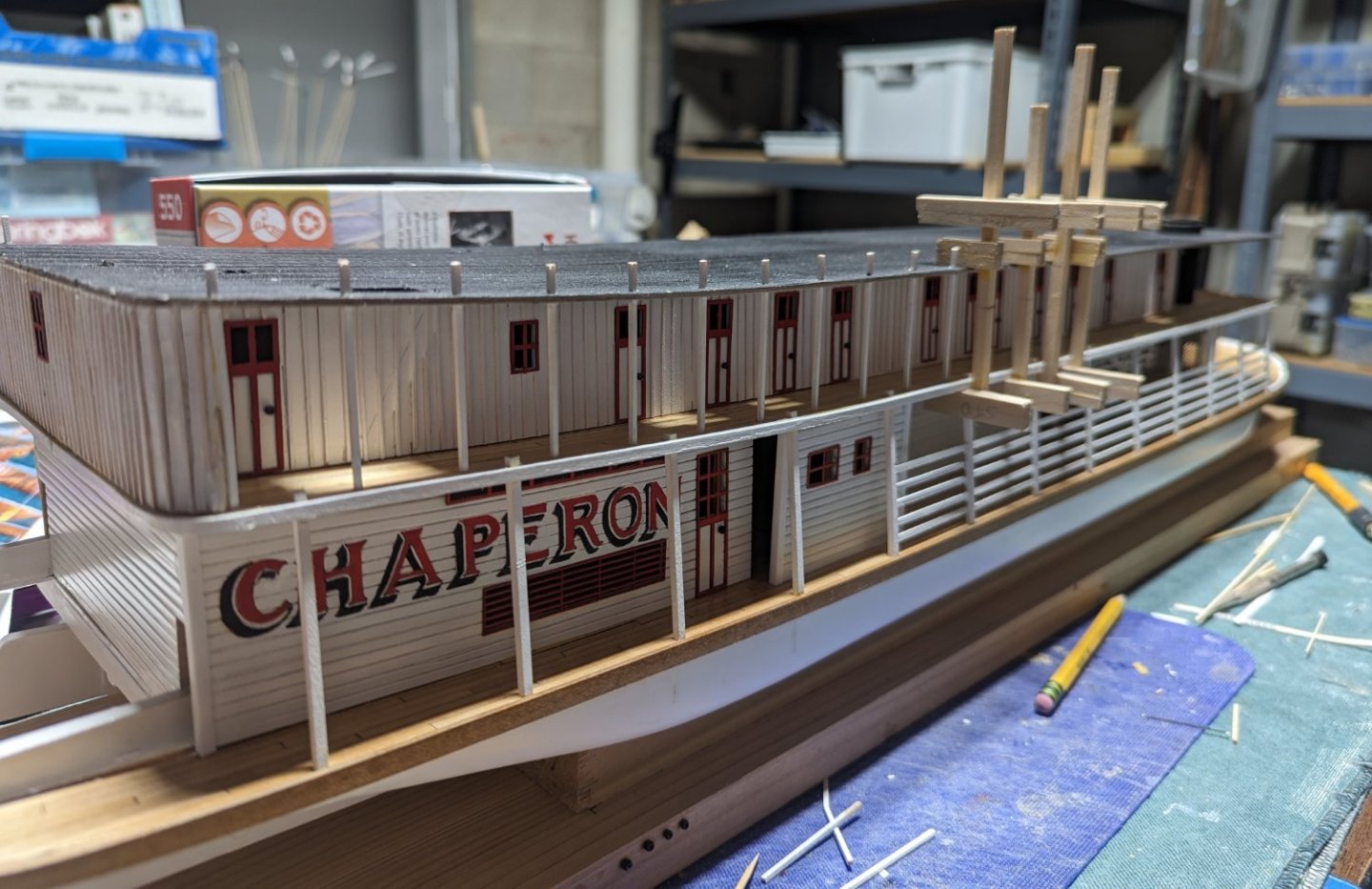
Cap strips and Hog Truss posts have been added
and Chicken Coop

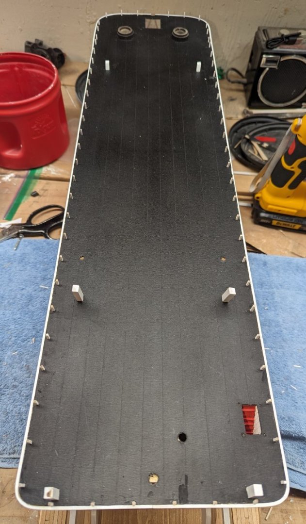
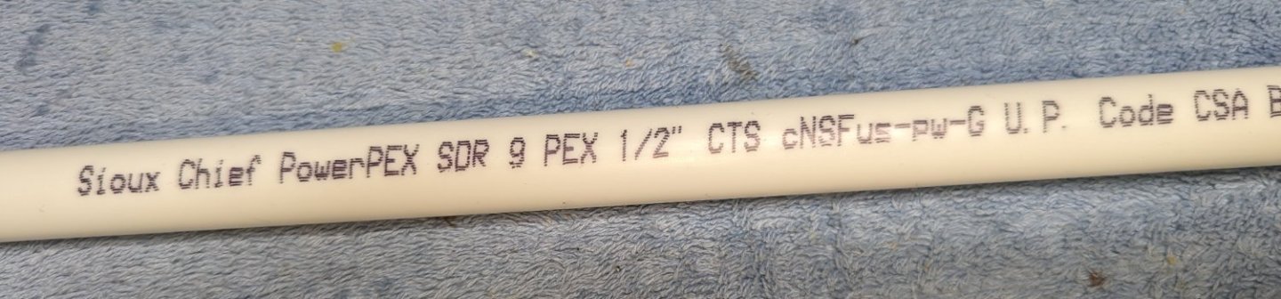
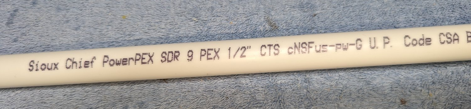
Started looking into the smoke stacks and decided i wanted to use some sort of pipe instead of the dowel rods. Looking at other logs, others seem to imply they used 1/2" PVC pipe saying the outside diameter is 5/8" (same as the supplied dowel rod). I am not sure what 1/2" PVC dowel rods they were referring to, but the 1/2" PVC pipe I have has an outside diameter greater then 5/8". I did find at the local box store that the 1/2" PEX pipe is the correct dimension as the supplied 5/8" dowel rod. You can get a short rigid 1/2" PEX pipe about 3' long.
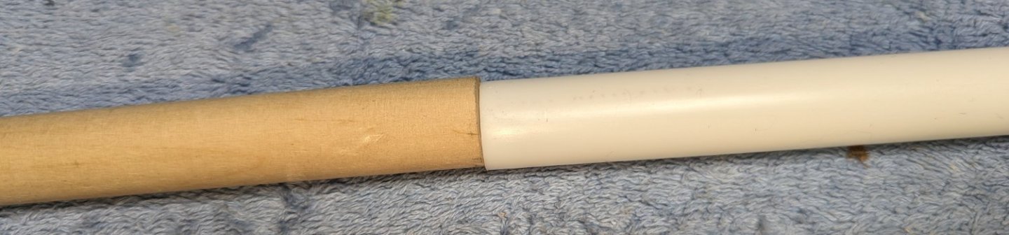
As you can see it fits exactly to to outside diameter of the supplied dowel rod. This is what I will be using for the smoke stacks when I get to that stage in the build.
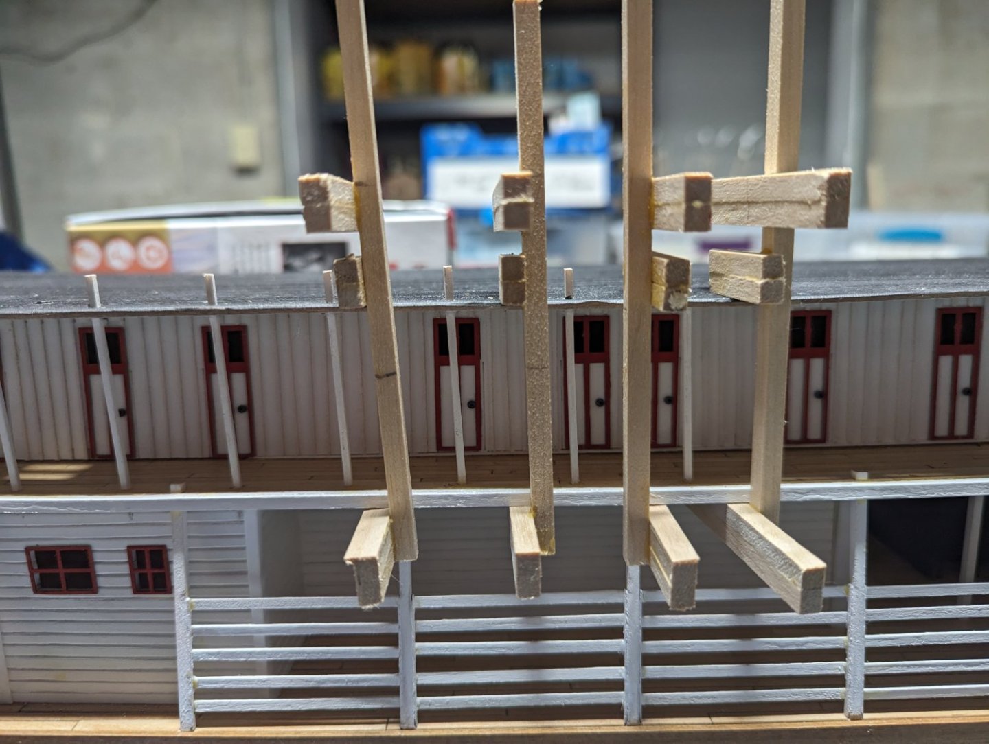
Here is an interesting "fun fact".... With the 1/16" square vertical posts installed on the Hurricane deck, it is not possible to install the back stairs. With the posts installed, there is not room to slide the stairs into place from the side. Even inserting the stairs at the bow of the boat and sliding it all the way, back back, I was unable to right it into place. Only option was to remove one of the posts, insert the stairs, and then replace the post.
Below shows post removed and stairs ready to be righted.
Once stairs were in place, post was replaced

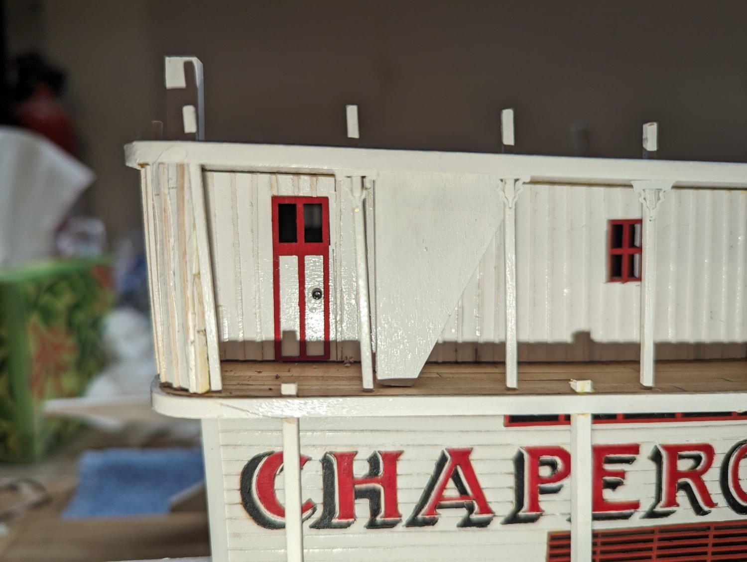
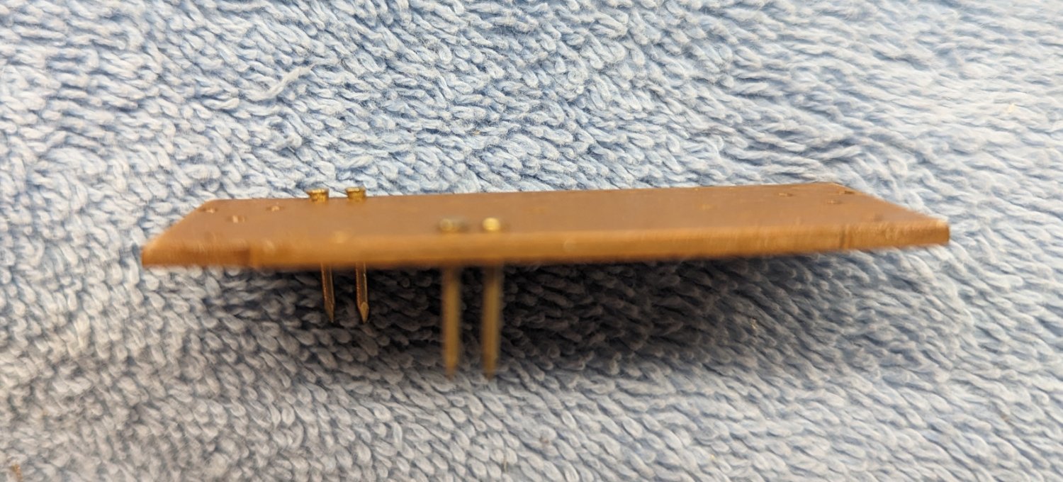
Decorative support brackets have been installed... I have a lot to learn about painting brass... I am not sure what the story was.... I primed the brass and then followed up with at coat of paint, but as the decorative support brackets were glued in, some of the paint came off and had to be repainted. I am not sure, maybe I should have sanded (scratched up) the brass before priming it as it is really smooth. I can see why paint has a hard time sticking to it. I need to look into that for the future.. Anyway, below shows the decorative support brackets installed
Sky light complete and ready for the Texas. Masing tape was used here too to simulate the tar strips
Texas house almost complete. As with the Hurricane deck the Texas has 1/32" squares battens. And as with the Hurricane deck they are a real pain in the $#%@.
Once all the battens were in place, just needs a another coat of paint and the doors.
And the top to the Texas. Again masking tape was used to simulate tar strips

-
From the comments above it looks like the quick indexes are being maintained, and I really do like them. But when I look at the tags for the various indexes, they all snow a date of Nov 2023. Are just the titles incorrect and in reality the indexes are up to date?

Thanks
john
-
Brian,
Thanks for the comments... I am no where near in the same class of builder that you are, but I have fun with it.
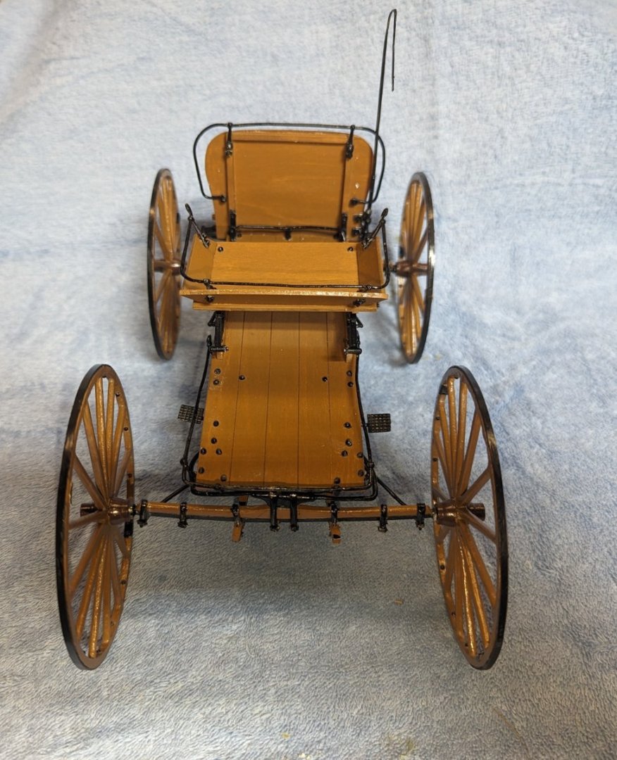
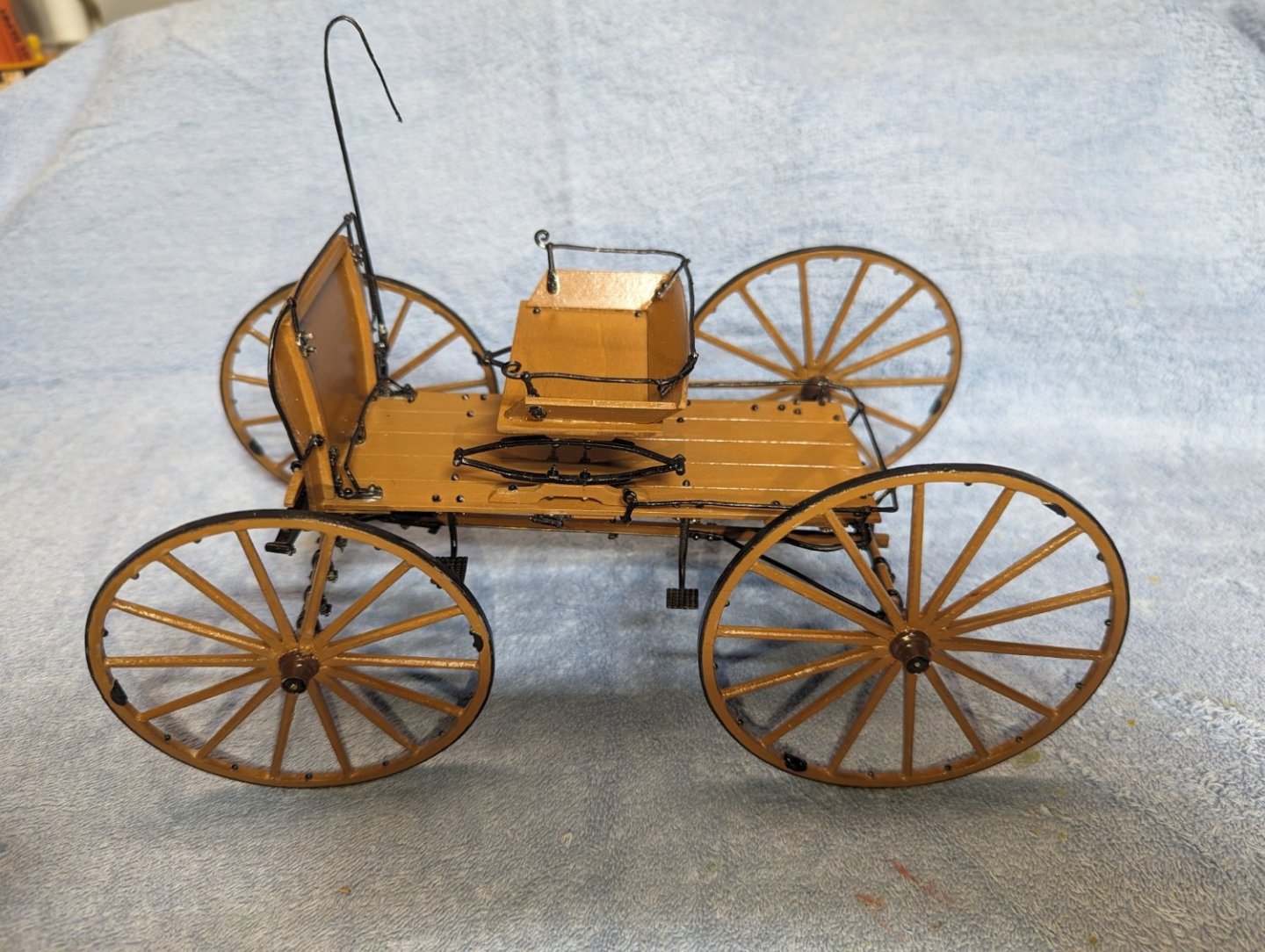
Here is a picture of the final Buckwagon.
If you care to see all the gory detail, below is the log

- Cathead, Ryland Craze and JerryTodd
-
 3
3
-
It has been about four months, but I am back.. Took a little break and worked on the Western Mountain Buckboard model. It is what I call a "quick win" and just want I needed to re-energize myself.
Back to the shipyard (Buckboard is not a ship)..
Just about completed the boiler deck stationaries (ran out of painted posts) and started the cap strips. They were previously bent and painted. Just waiting for the boiler deck stationaries to be completed.
-
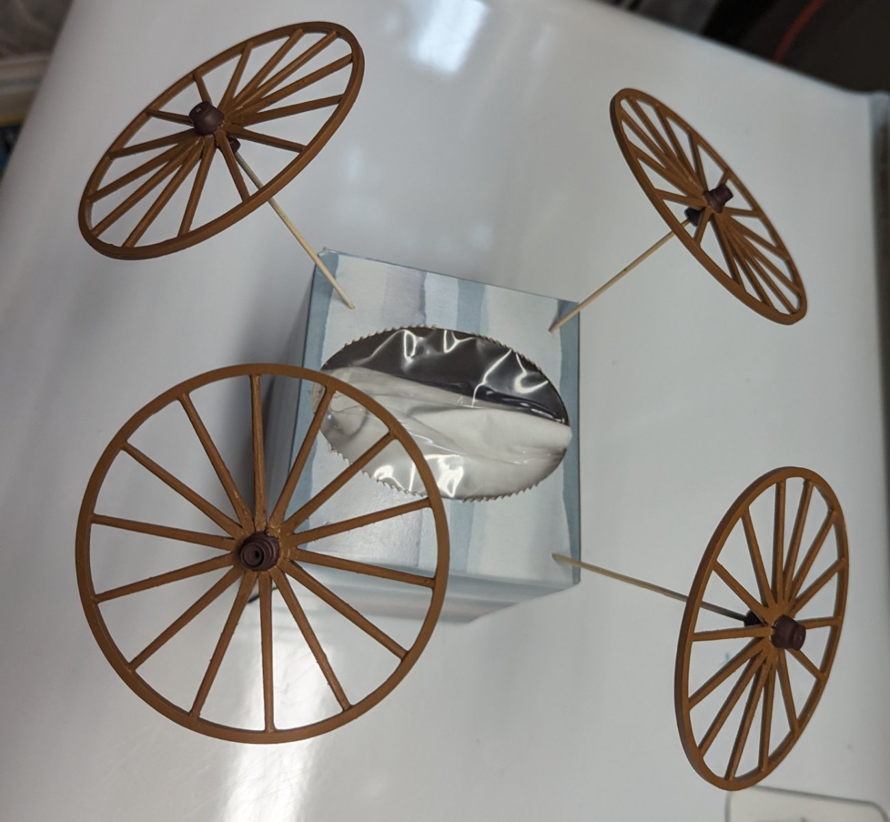
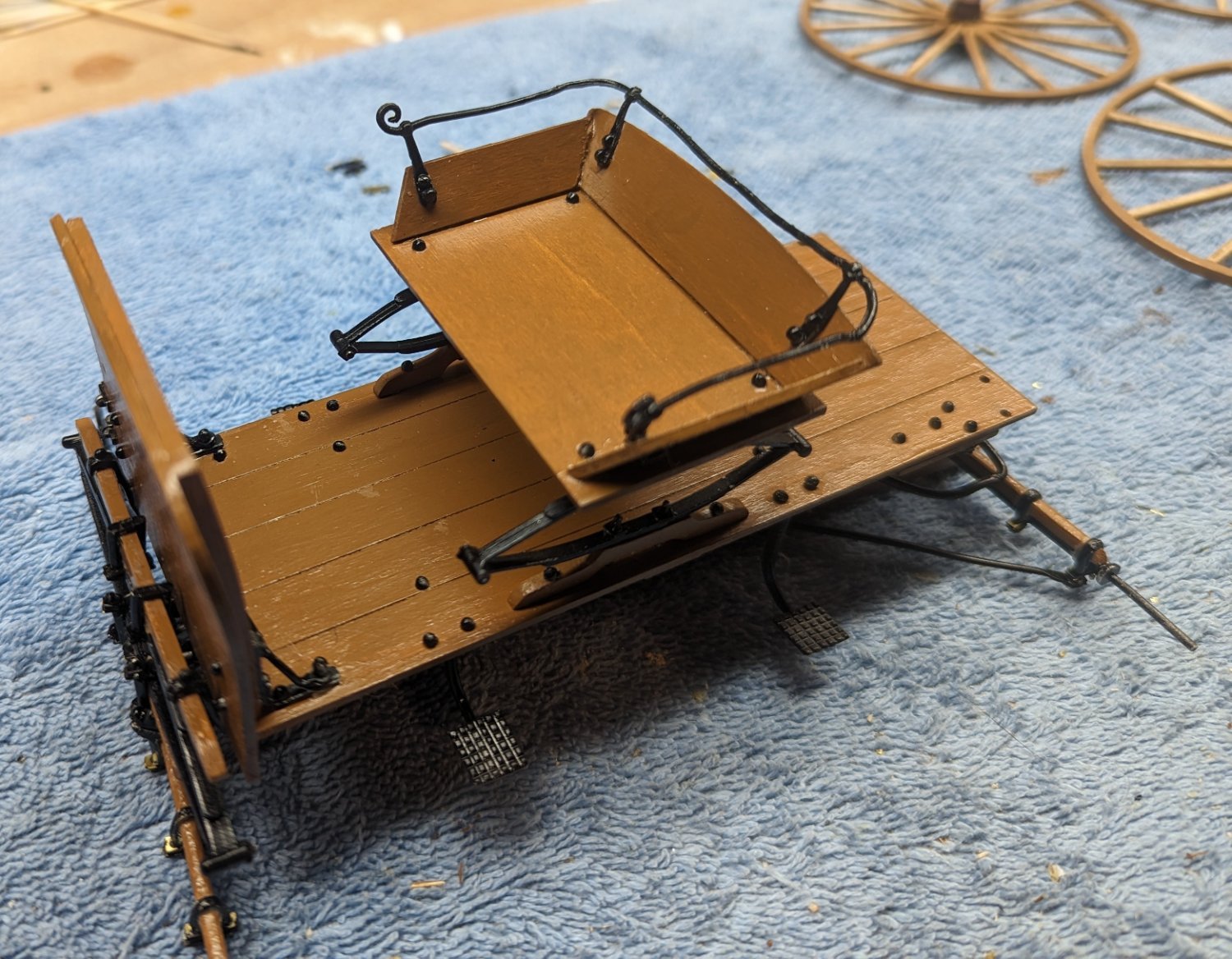
Only thing left to do is mount the wheels and add the large nuts to the axle (to keep the wheels on).
The four large nuts are made/cut from the same rubber like material used for the outside of the wheel. Instructions all to glue two of them together to make what looks like a large nut.
Below shows eight rubber nuts guided together to form four large nuts.
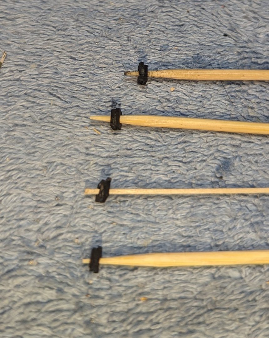
Mount the wheels and add the nuts to each axle, holding the wheels on. If you look close you will see one of the nuts inside the hub on the axle.

With at, all that is left to do is add the whip and I am "calling it" done...
For anyone you is interested in building the Buck Wagon, below are a few points to consider. All of these have been mentioned above along the way, but here is a summary.
1) The 3/16" bolts are too short of many of the places that call for 3/16" bolts. Before you begin, I would contact Model Expo and have them send you some extra 1/4" nuts. They easily fit in those spaces the 3/16" bolts are too short.
2) The supplied nails are way oversized and the heads are cone shaped instead of flat. Since the bottom of the wagon could not be seen, I decided not to use them there, but by the time I reached the wheels, I still could not see using the supplied nails. For the wheels I purchased much small nails and they worked great. If you are going to purchase smaller nails, purchase enough to cover the bottom of the wagon too in addition to the wheels.
3) The Reach plate assembly (to me anyway) was really unclear. I studied it a long time (way too long) trying to figure it out. It finally came to me, but unless you already know about Reach plates, you will spend some time trying to figure it out. Hopefully some of the pictures I supplied above will help.
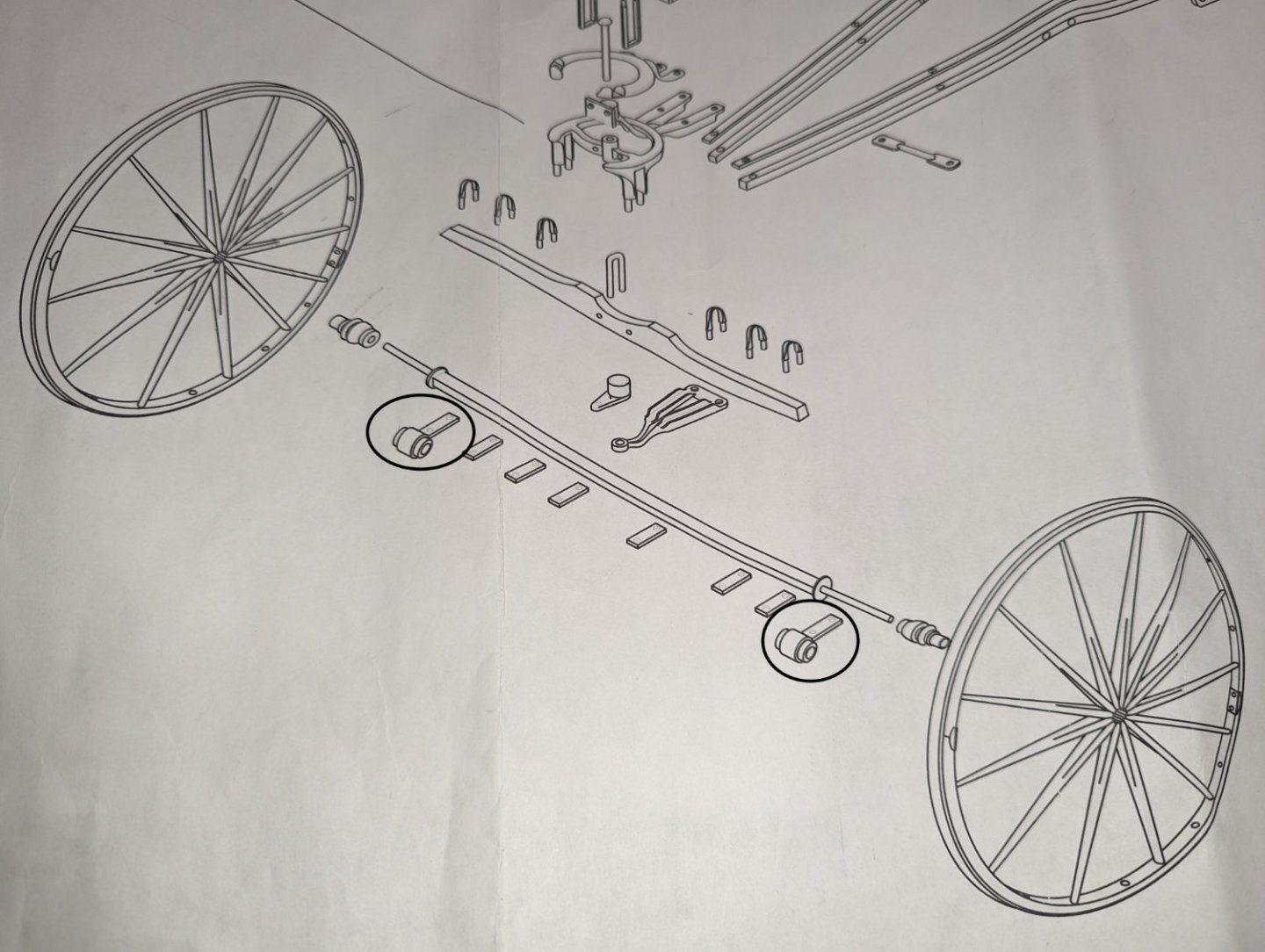
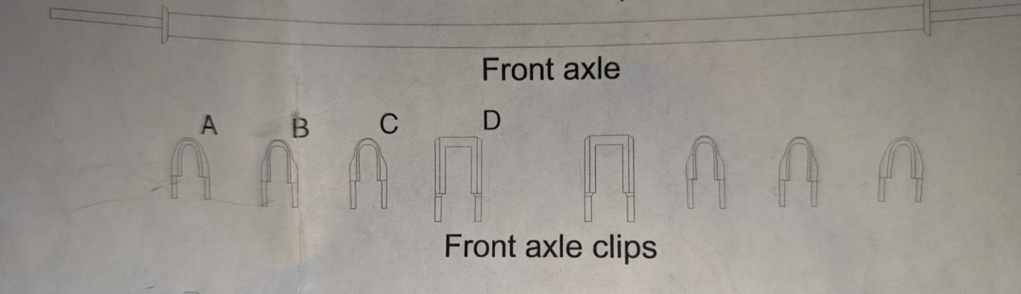
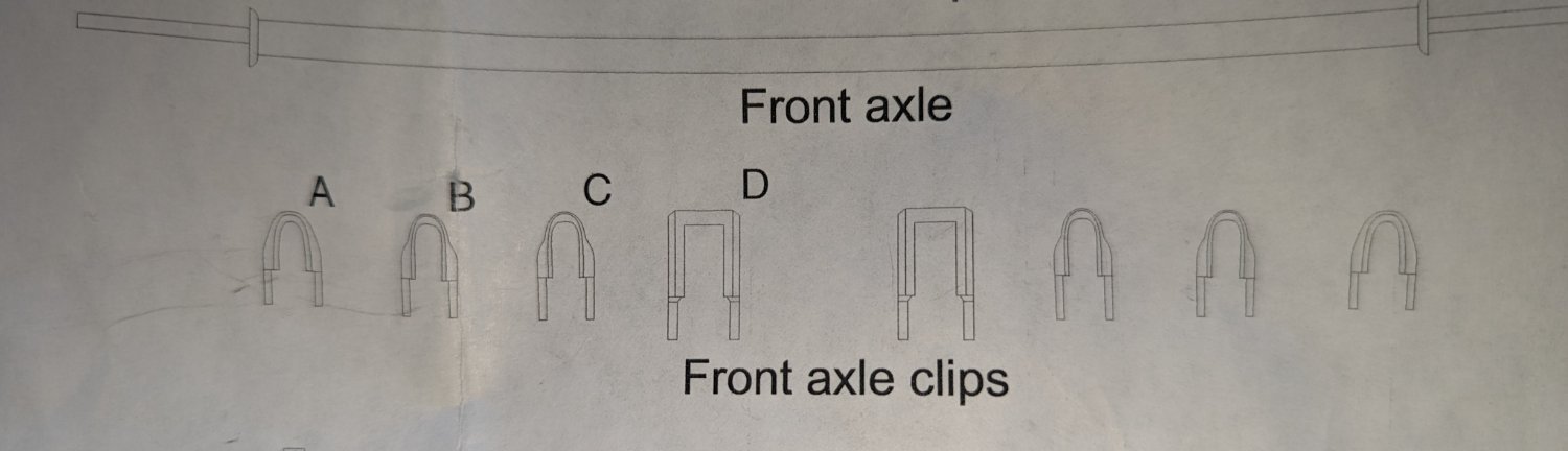
4) The axle coupling (not sure what purpose it serves on the wagon), really should be on the front axle. Diagrams are not real clear as to the exact size and location of the front axle clips. Be sure to fit one of the longer clips on the outside so to have room for the axle coupling.
For me it is back to the Chaperon Riverboat. I was about 3/4 they way though that build and I needed a break. I took on the Buck Wagon as a "quick win" and a break from the Chaperon... Have been revitalized, I am going back to the shipyard and complete the Chaperon.
- bobandlucy, Jack12477, gsdpic and 5 others
-
8
-
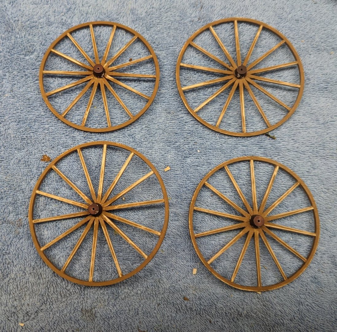
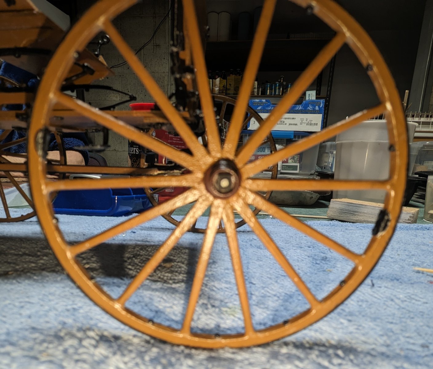
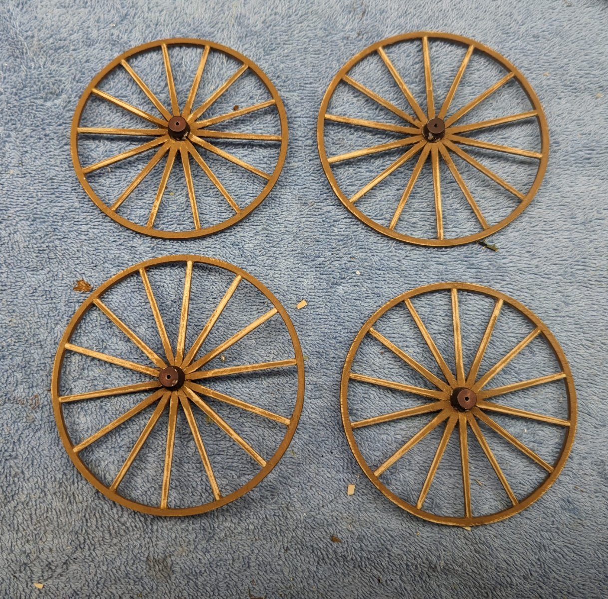
On to the wheels. All four wheels went together very well and stained

As mentioned early on, the nails supplied are grossly oversized. Earlier I mentioned skipped them on the underside of the cart. but the wheels really needed some sort of nails. I went out an purchased some smaller nails that fit the bill perfectly. Holes were drilled between each spoke and a nail (with black painted head) was inserted. Below you see some of the nails with sticking out of each wheel. After all nails were inserted, they were clipped off the outside of the wheel and files smooth.

Final version of one of the wheels with nails cut off, rim cleats added, and gasket material added on the outside of the wheel.
At this point instructions all to cut little swales between the nails on each spoke. Sounds good in theory, and it actually looks good in the pictures, but someone of my skill just could not handle it. I started out making the swales (about 10 or so), but I just could not get them consistent looking. Seemed each swale was different and the overall look was horrible. I took some wood filler and covered up my mistake. So my wheels will not have the swales. What you see below is how they are going to look.

On to the apron... Not much to say here... goes on pretty easy.
Likewise with the luggage rack..
Only thing I will say here is with these two parts, and like the other Britannia parts with the model, they are so thin that they bend out of shape just looking at them... Lots of fun with Britannia 🙂
-
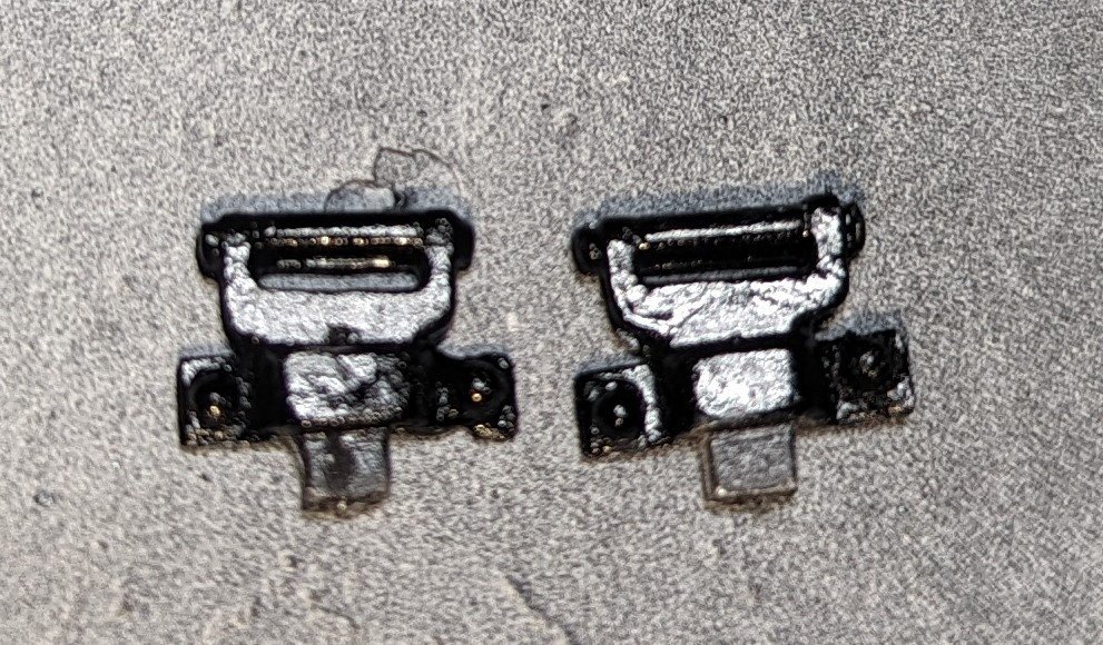
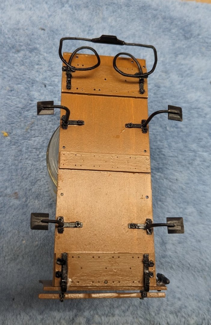
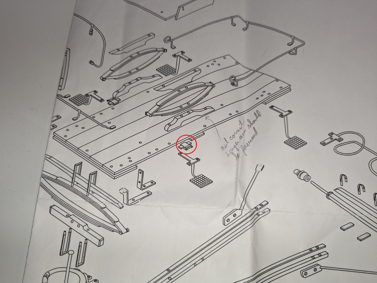
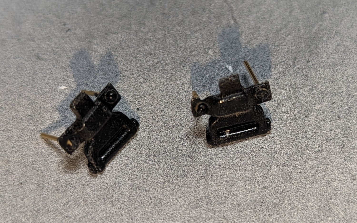
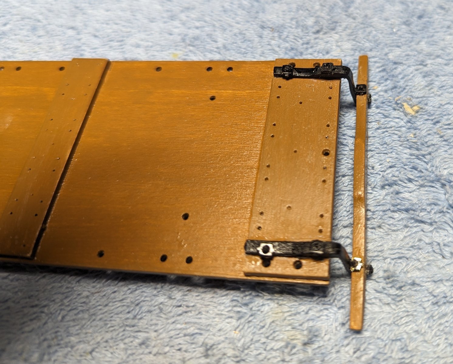
There are two parts to the cart that are not mentioned in the instructions... Axle Couplings and Wheel Rubs. They are shown in the diagrams, but not very clear (to me anyway) as to where they belong.
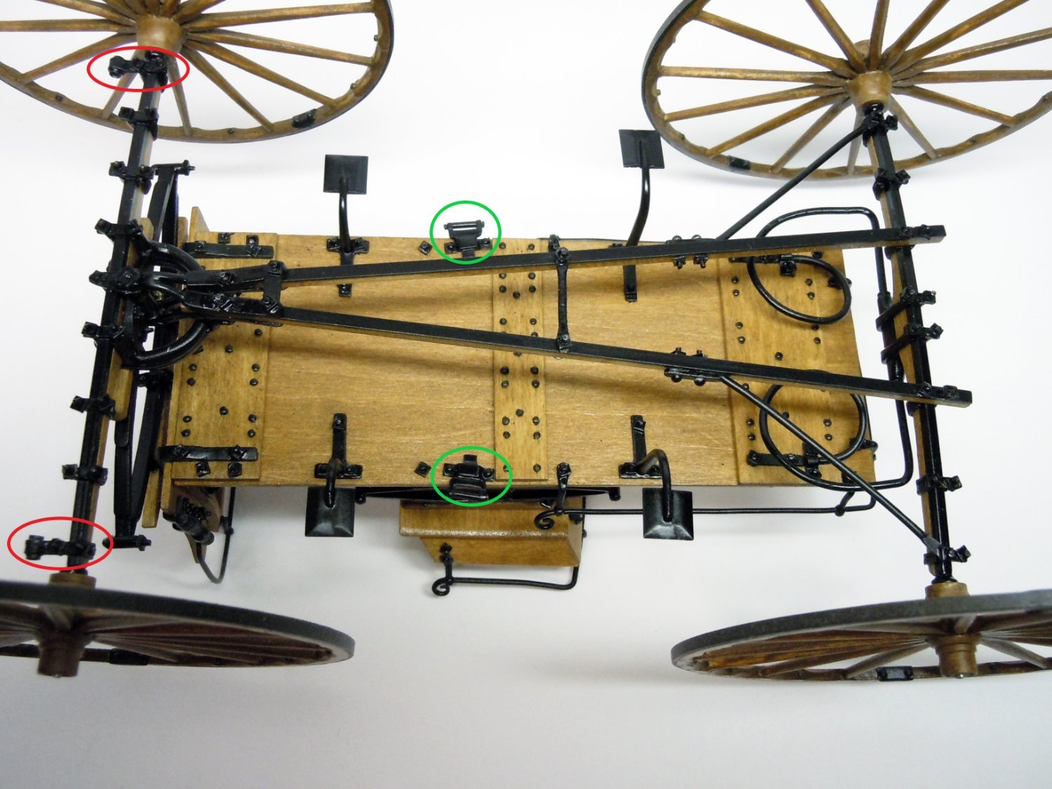
Below are the Axle Couplings (in black) and Wheel Rubs (in red).

I contacted Model Expo in requesting a picture of their cart showing the location of these parts.
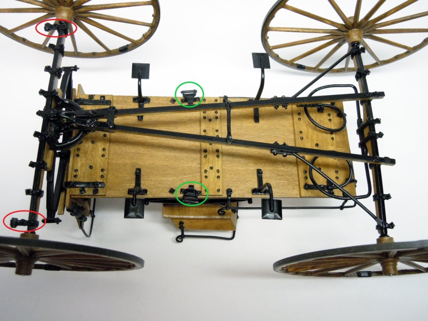
The below picture was returned. Note the location of Axle Couplings (in red) and Wheel Rubs (in green). A picture is worth a thousand words.
At this point I have an issue. Looks like the Axle Couplings only go on the outside clips of front axle. When I assembled the front axle, the front axle diagram showed all the front axle clips to be "about" the same size, with each one a little longer. If you look below, the diagram shows the clips going from short to long on the axle from outside to inside. My problem now is the short clips at the end of the front axle are not long enough to hold the Axle Couplings. I think at this point I am going to skip them. I am not even sure what they are supposed to do. To me an axle coupling function to join two shafts together. From the picture they do not seem to server any purpose. Put them on if you want, but to me it is not worth (at this point) switching some of the longer for shorter clips just to add the Axle Couplings.Below show the Front Axle clips I mentioned above. As you can see, it shows the clips going from short to long on the axle from outside to inside. If you follow the instructions (as I did), you will not have room for the axle coupling fittings on the outside clip. Not a big deal, just swap the last two clips and you will have plenty of room and the shorter clip will fit just fine as the 2nd clip inward.
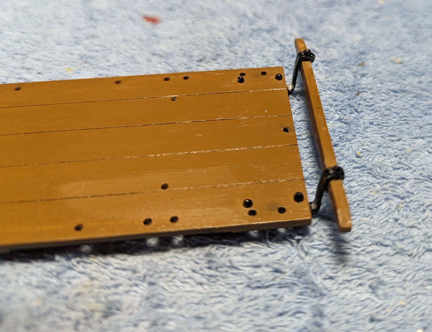
As for the wheel Rubs, they have a couple small holes in them for bolts. Bolts do not go through the deck. Cut the heads off some small bolts and inserted them into the holes to show they are bolted to the underside of the cart.
Wheel rubs with small bolts stuck through the holes
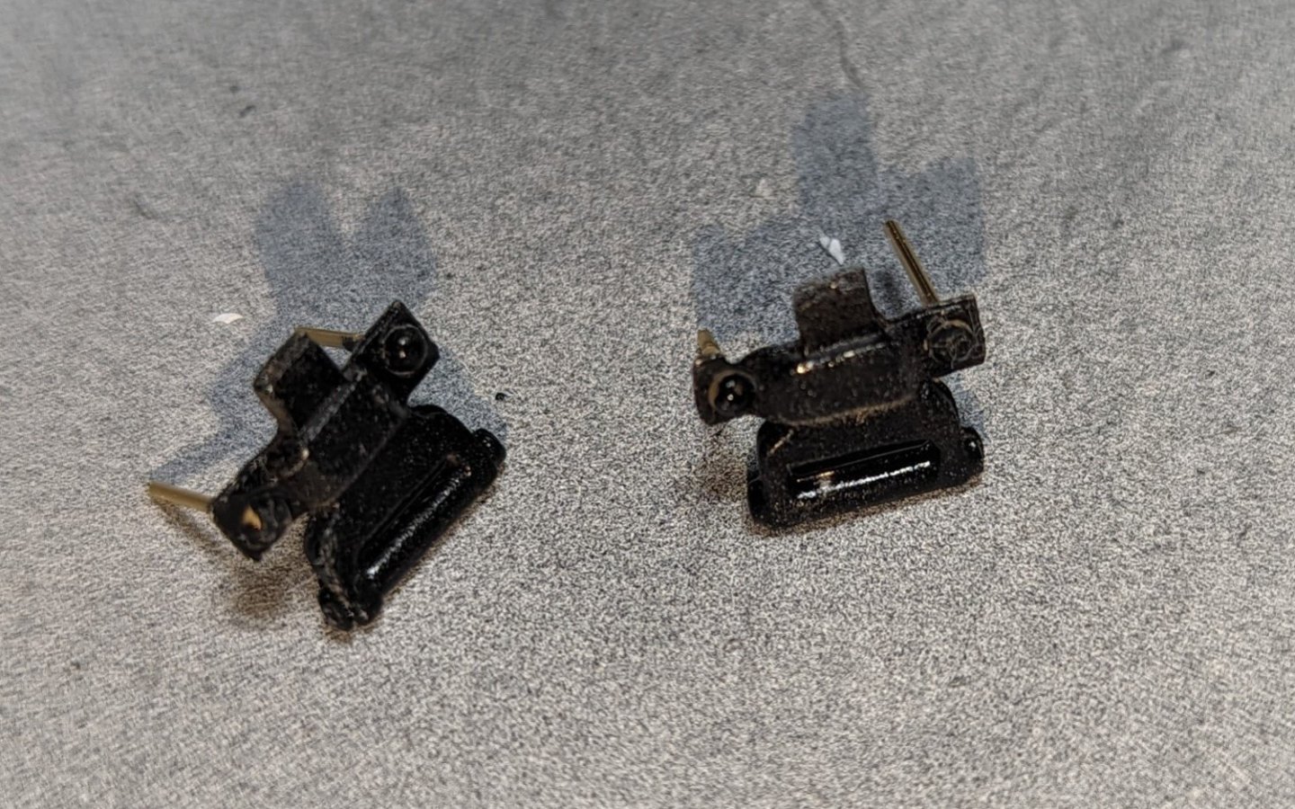
And with the bolt cut off
Anyway, I just wanted to insert this topic on the Axle Couplings and Wheel Rubs as it is a little confusion as to where they are located. Hopefully this will help someone down the line.
- Jack12477, Ryland Craze, Egilman and 4 others
-
7
-
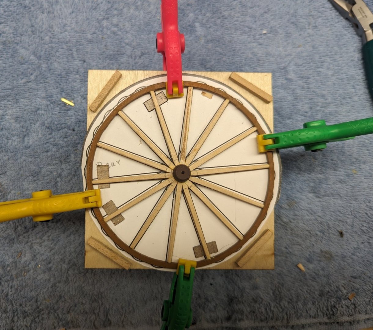
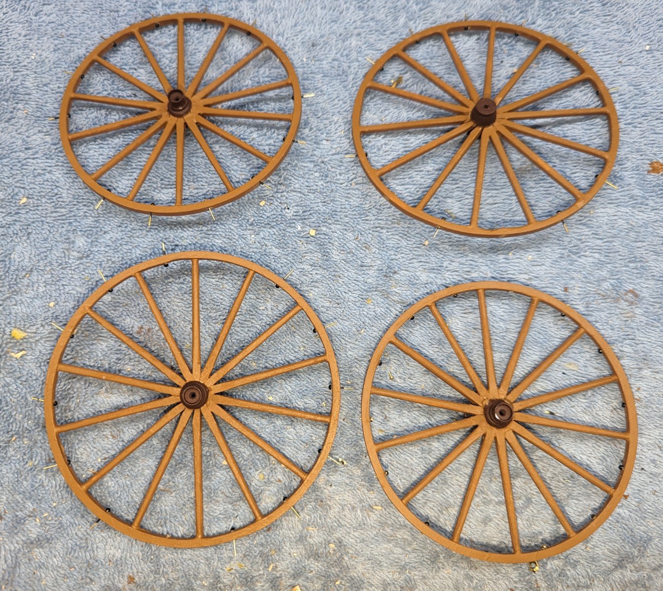
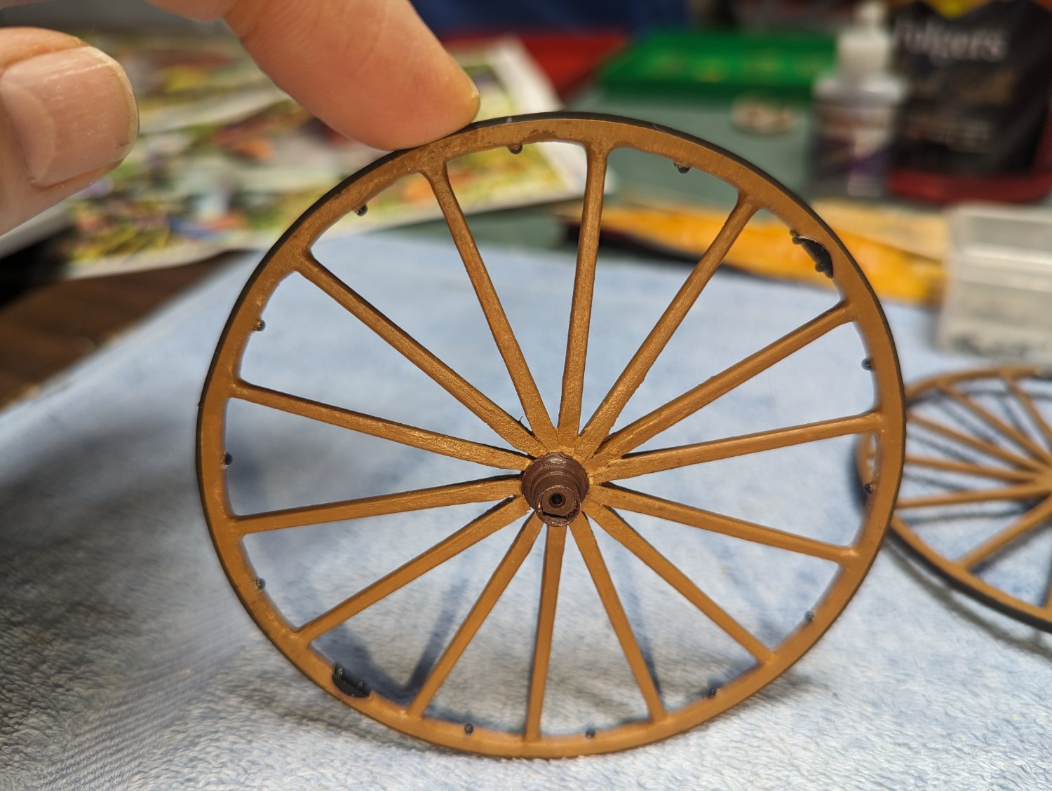
Completed adding the spokes to the wheels and doing some fine tuning on the spokes. I have have made a mistake earlier when I indicated that it would be easier to do the bulk of the spoke trimming before they were glued into the wheel. Turns out that may not have been the case. While doing the fine tuning, it was easier then I expected and the spokes are well glued into the wheel. I might suggest following the instructions (who does that?) and do all the trimming of the spokes after they are in the wheels.
Still have to add the tire bolts, round the edges, and re-stain, but these wheels are close to being done. Speaking of tire bolts, they call to use the same nasty nails that were supplied for the underside of the carriage. For these I ordered some more appropriate size bolts. Hopefully they will arrive in the next few days
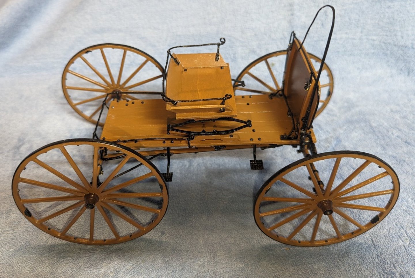
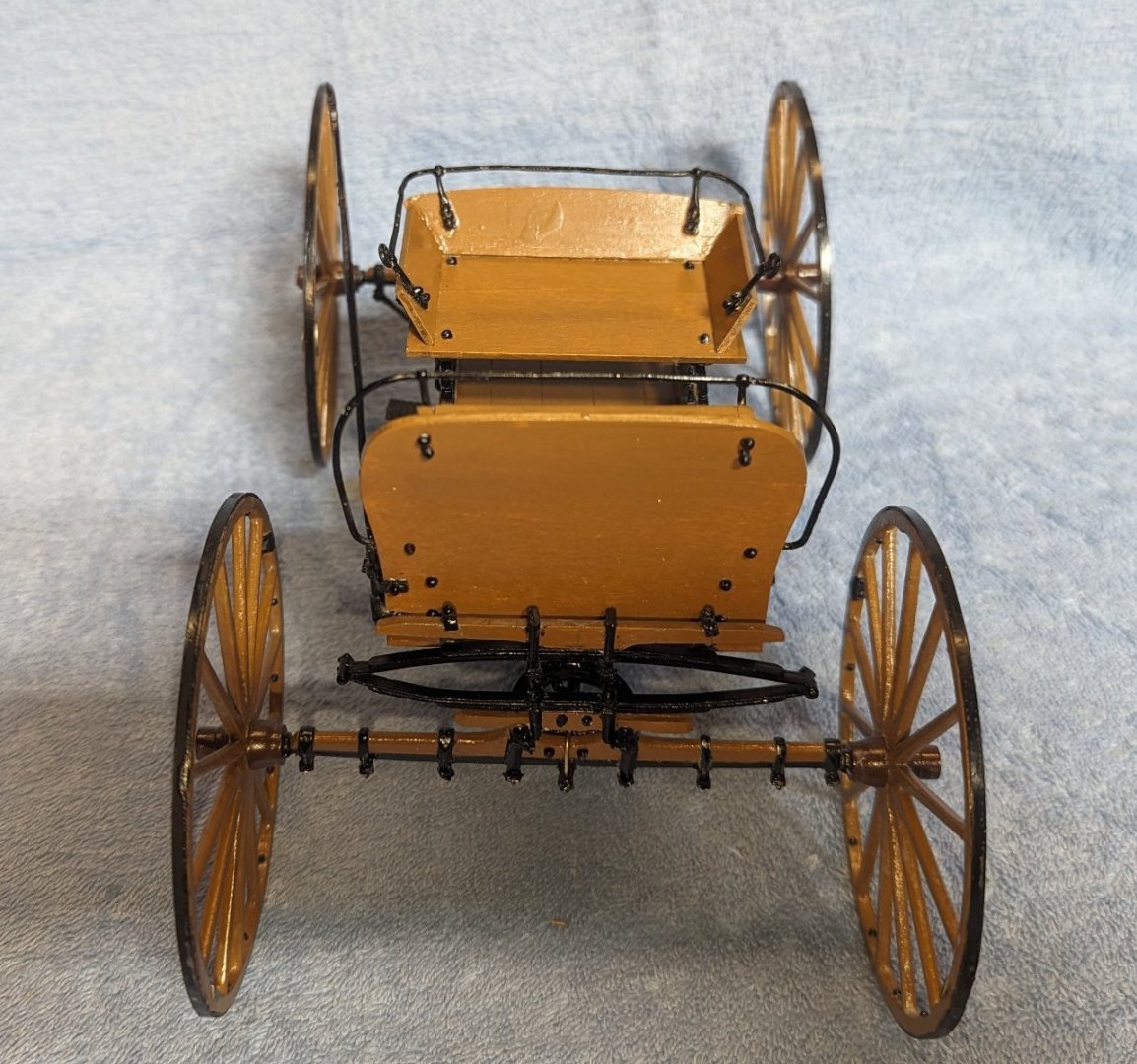
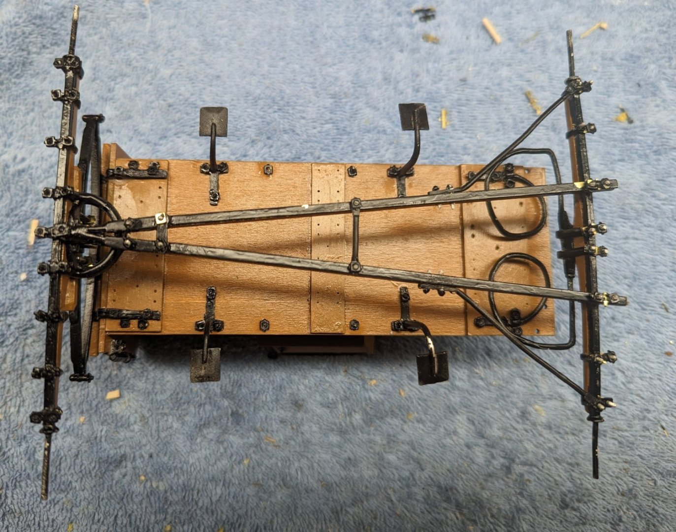
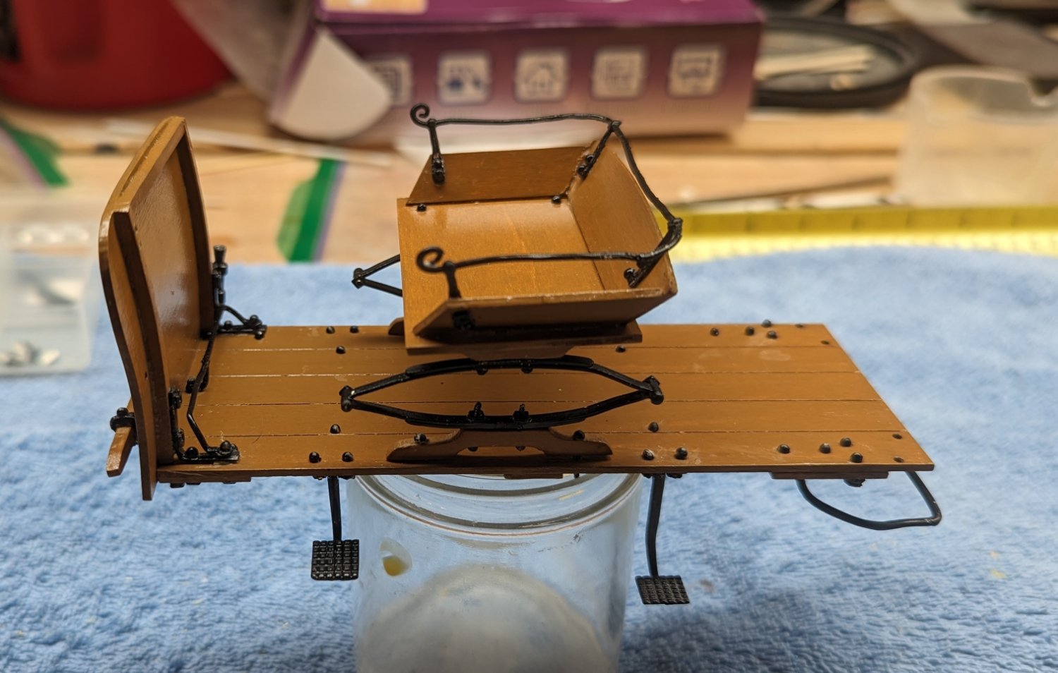
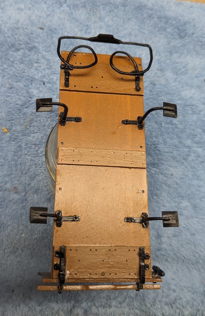
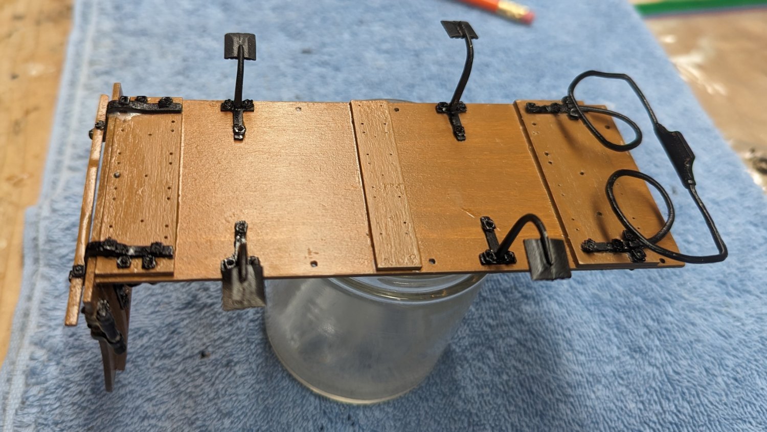
Nearing the end. Below are a few pictures of the current status. Will still need to touch up the paint here and there at the end.
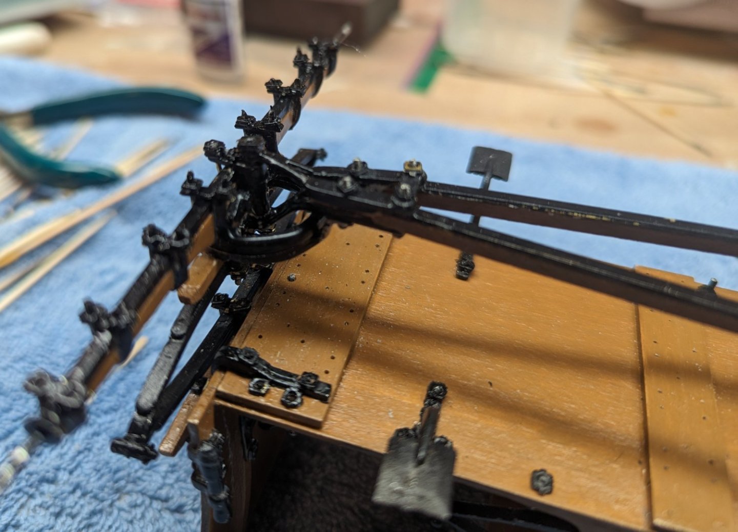
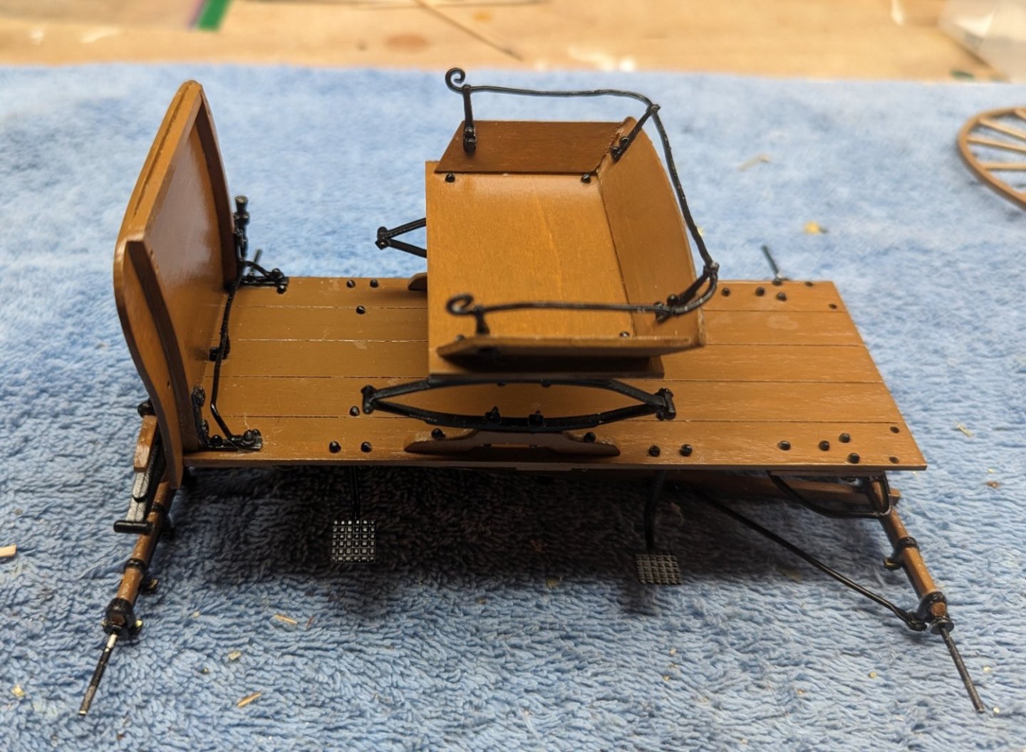
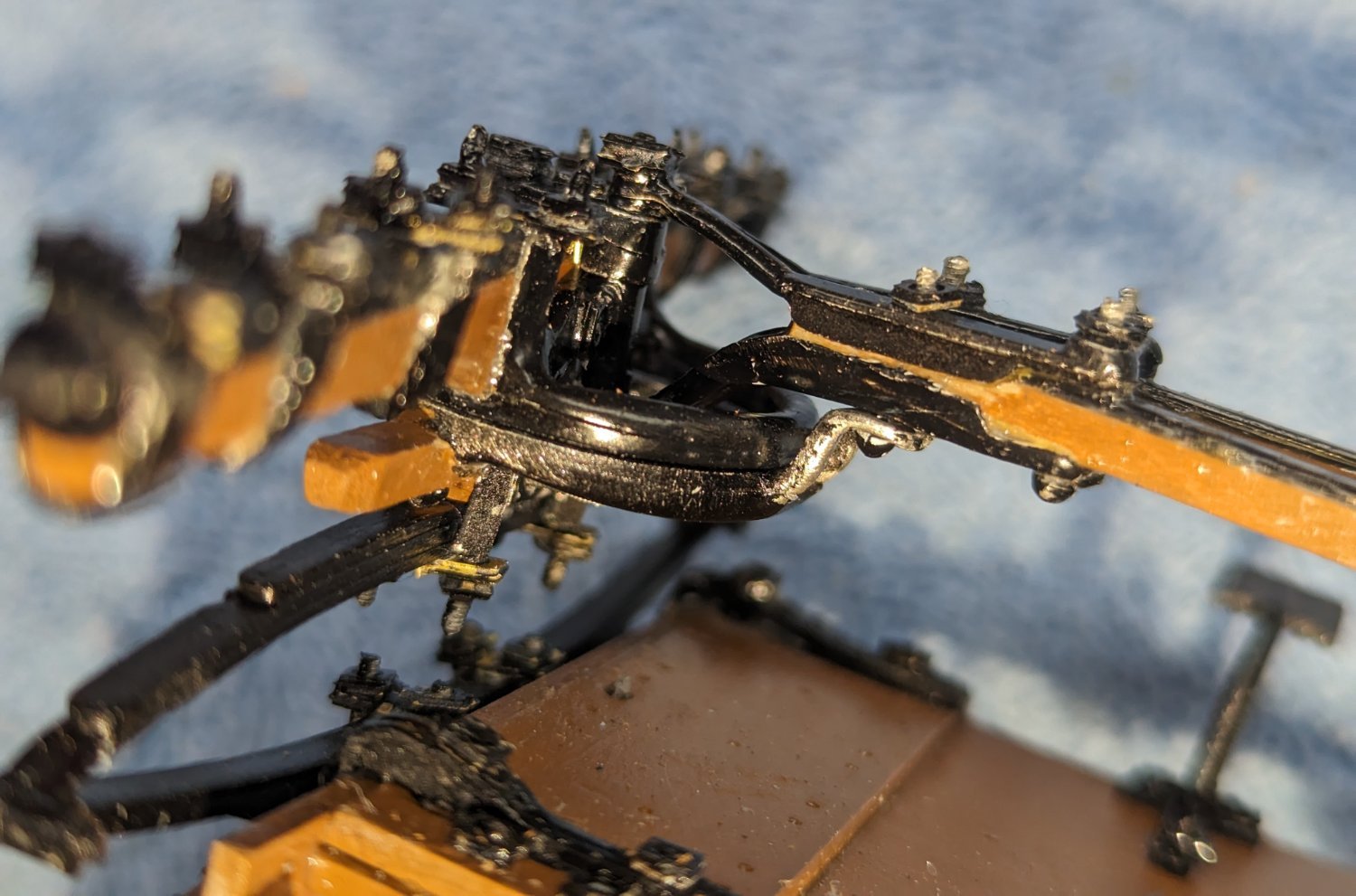
All Reach Assembly parts have been added.
A couple close ups of the forward Reach Assembly parts.

And some overall pictures of the current status
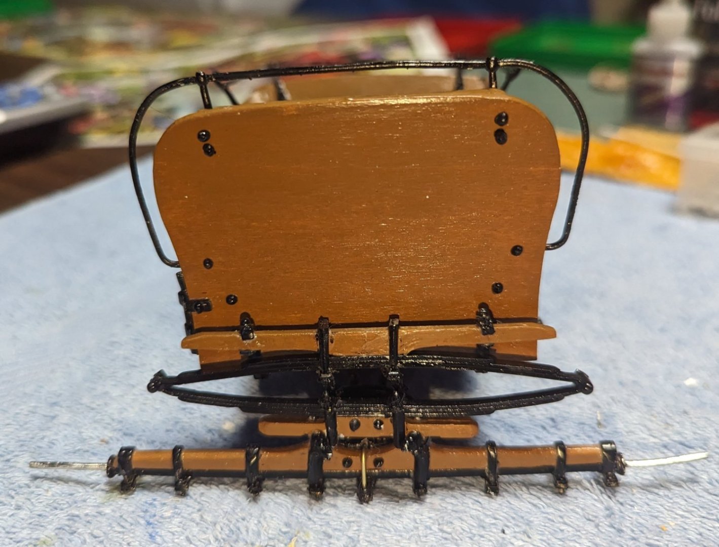
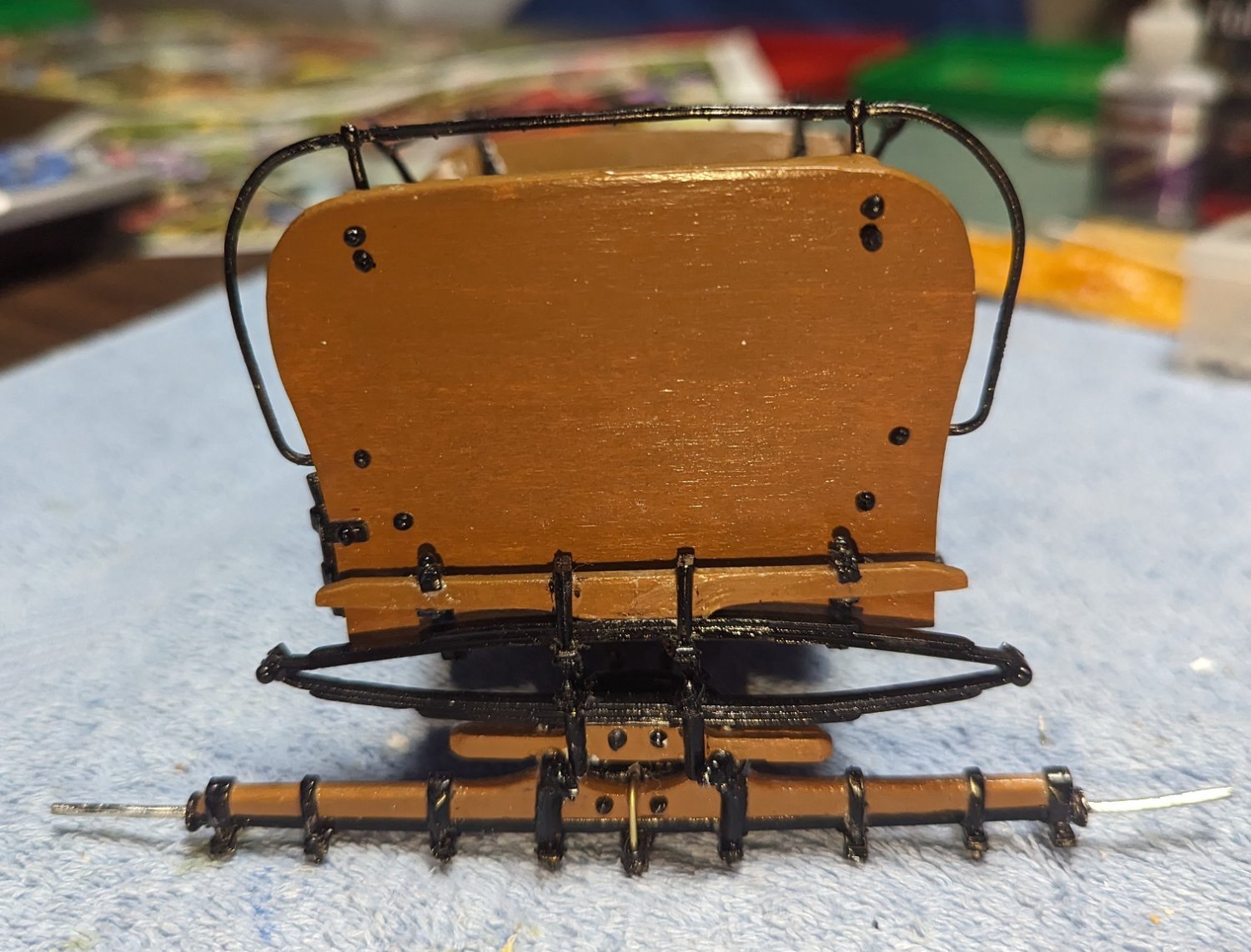
Rear view
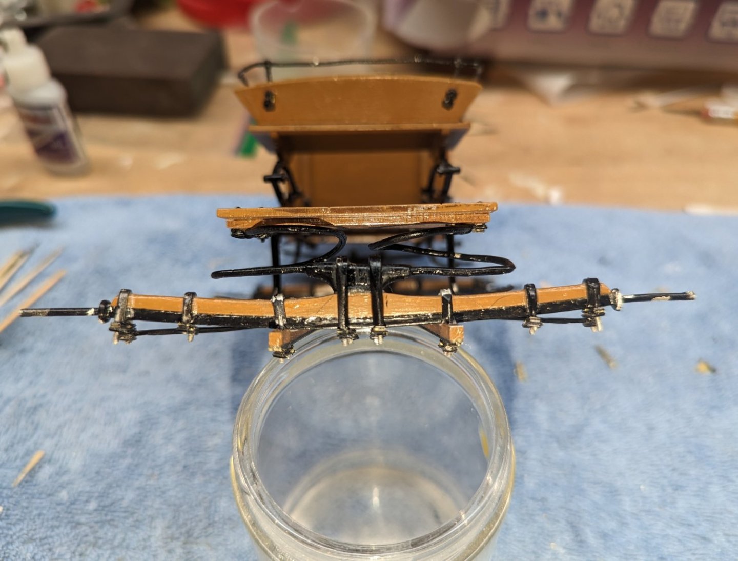
Front view

And a couple overhead shots

Next plan to add the Luggage Rail, Apron, and whip
-
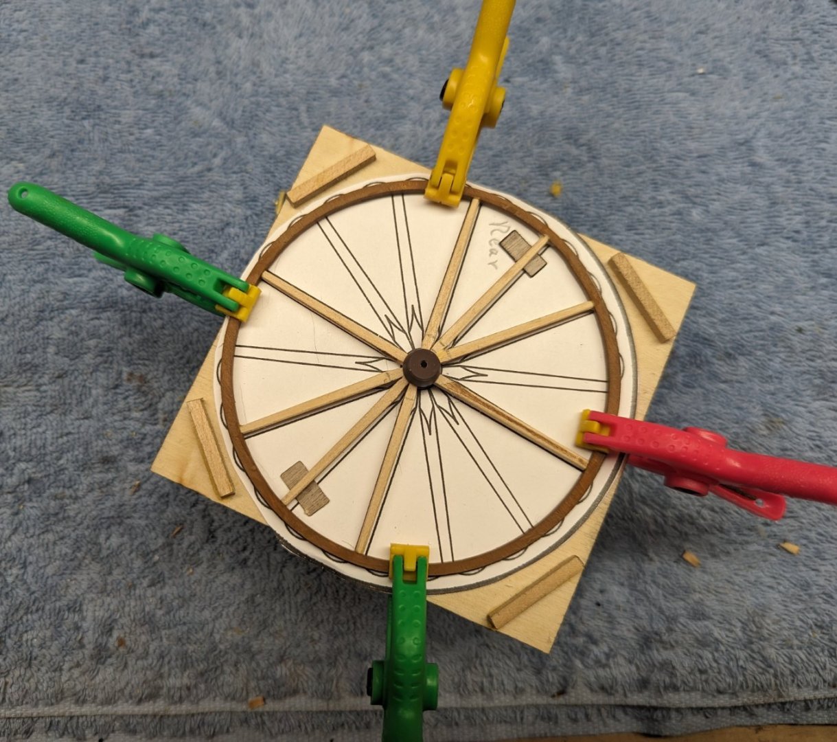
Prior to completing the Reach Assembly, I decided to take a break (for my eyes) and move on to the wheels. Assembling the Reach Assembly, with all the tiny screws and bolts, is defiantly not for weak eyes or large fingers. Quite a challenge.
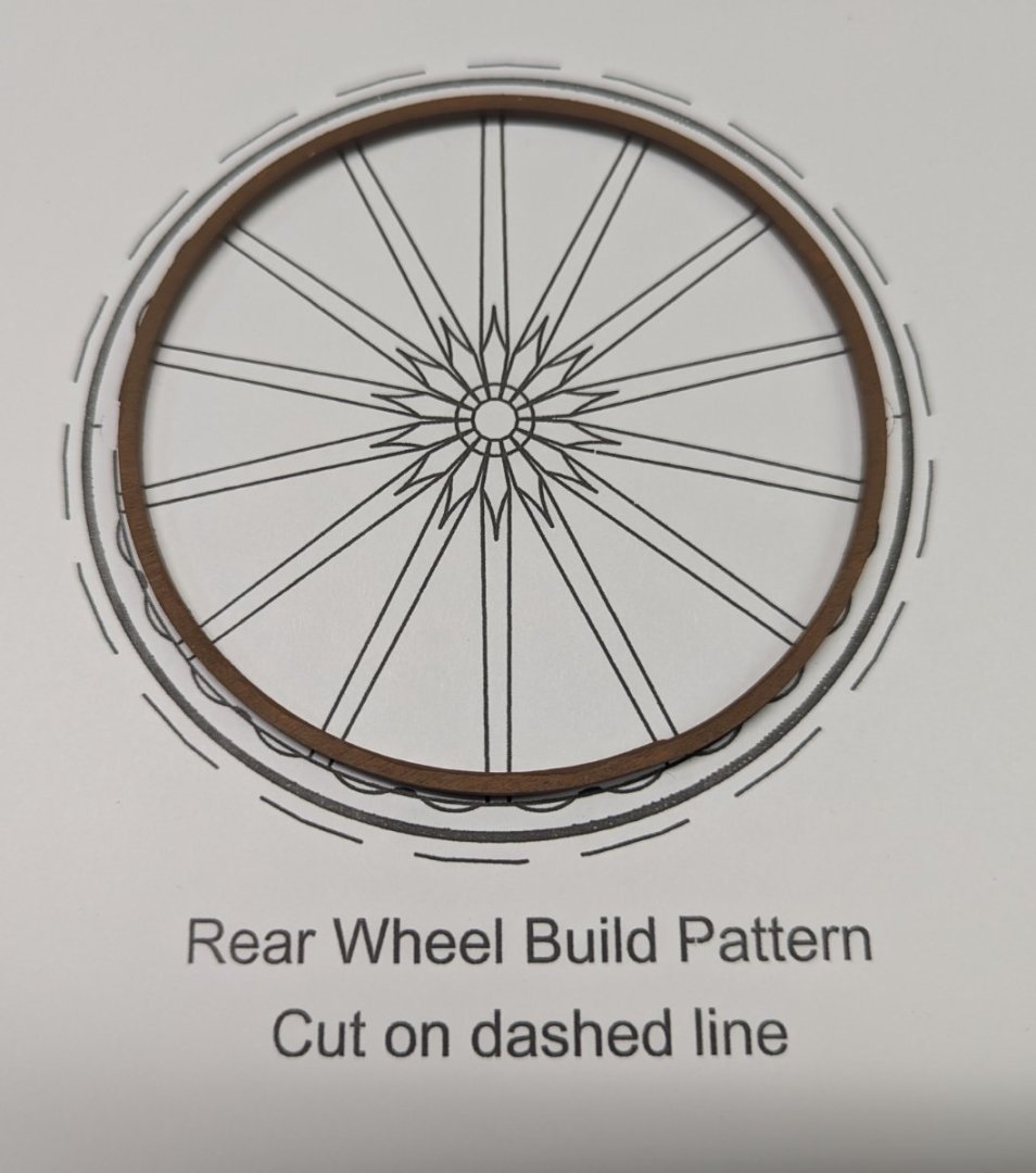
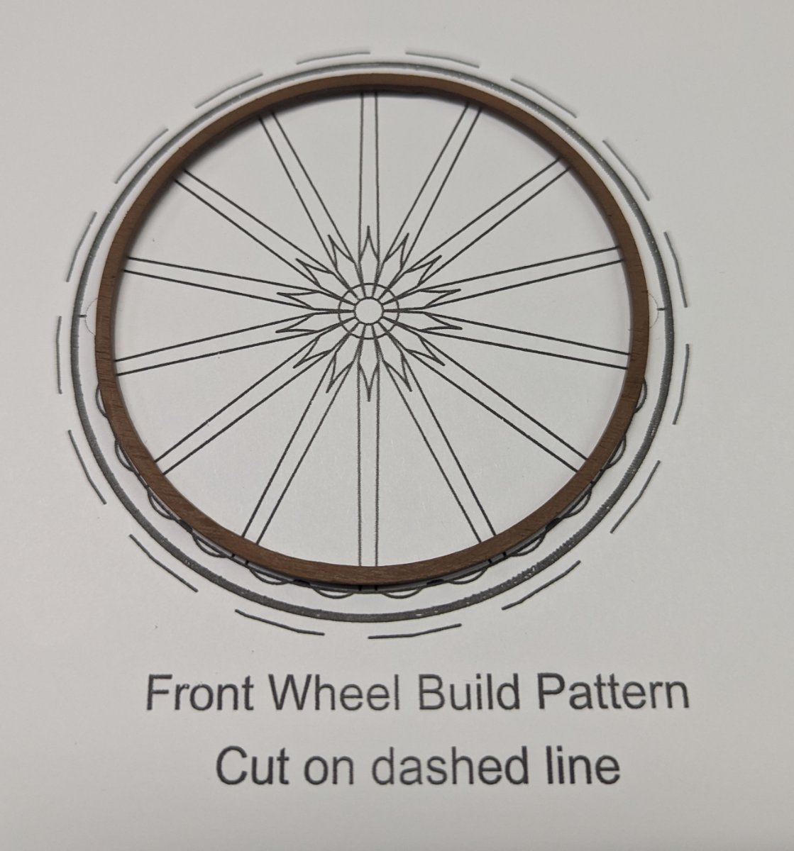
Instructions call to cut out the "life size" wheel patterns from the diagrams and use them on the jig to assemble the wheels. Here is an interesting "fun fact". The life size diagrams are not life size. Note below the outer edge of the wheel only matches up with the inner edge of the diagram. Over time either the wheels have gotten smaller or the diagram grew. Not a big deal as only the inner portion of the diagram is used to position the spokes. Not sure why I even mentioned this, other than an interesting "fun fact".

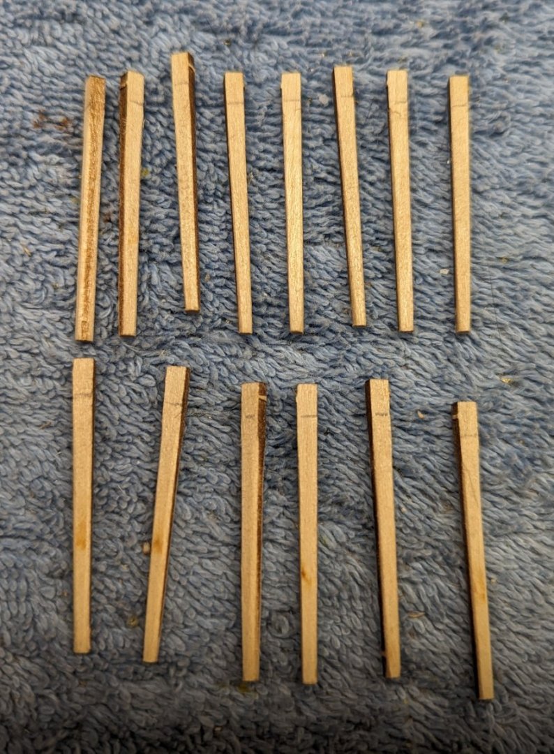
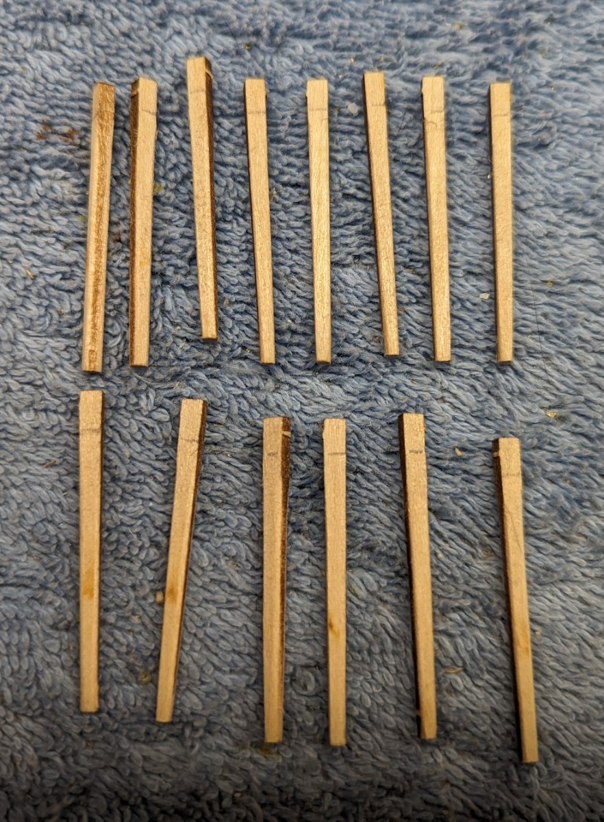
For some reason the instructions call to assemble and glue all the spokes into the wheel and then trim them down to an oval shape. At my skill level, to me that is asking for trouble. Instead I choose to trim the spokes down before they are assembled into the wheel. Maybe after assembly I will do some fine tuning of the spokes, but the bulk of the trimming was done prior to assembly into the wheel.
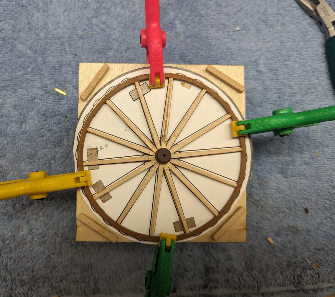
One thing to watch out for... As you might expect the wooden wheel is pretty weak prior to adding the spokes. Instructions call to clamp it down to the jig with four clamps. That part is good, but before you start gluing in spokes, dry fit four spokes (at opposite sides) to verify the wheel has remained round. Even though it looks round, chances are when adding the clamps it became a little out of round. The spokes are exactly the minimum length. If the wheel is any out of round, the spokes will be too short on at least one of the sides. In fact, initially when I was dry fitting them, the wheel was a little out of round (but not to my eye) and I thought the spokes were too short and I would have to make all new stakes. Fortunately I realized the clamping put the wheel out of round and corrected it so all the spokes would fit. Even then, with the spokes being the exact minimum length they are barely were long enough. It have been helpful if the spokes were a little longer.
Once you have verified the wheel has remained round after the clamps, then start gluing them in. I choose to glue in two at a time on opposite sides.

- davec, Ryland Craze, hof00 and 5 others
-
8
-
Starting on the front and rear axles. Below is the result of gluing the wood axle caps on both axles. This is a good time to dry fit the wheels hubs onto the axles. The instructions do not call for this until the very end of the build when you are attaching the wheels. In my case, the wheel hubs did not slide onto the axles. The axles were a little thick vs the hole in the hubs. The axles had to be filed down some so they would slide on. Much easier doing this now than at the end when the cart as been built.
Note on the front axle, behind the large hole for the King bolt, should be a very small slot in order to later apply the brass rod that will eventually be bent around the head plate. Verify at this point the brass rod will slip behind the hole for the King bolt. You may have to use the small drill bit and enhance the slot.
Read Axle attached to the read spring bar

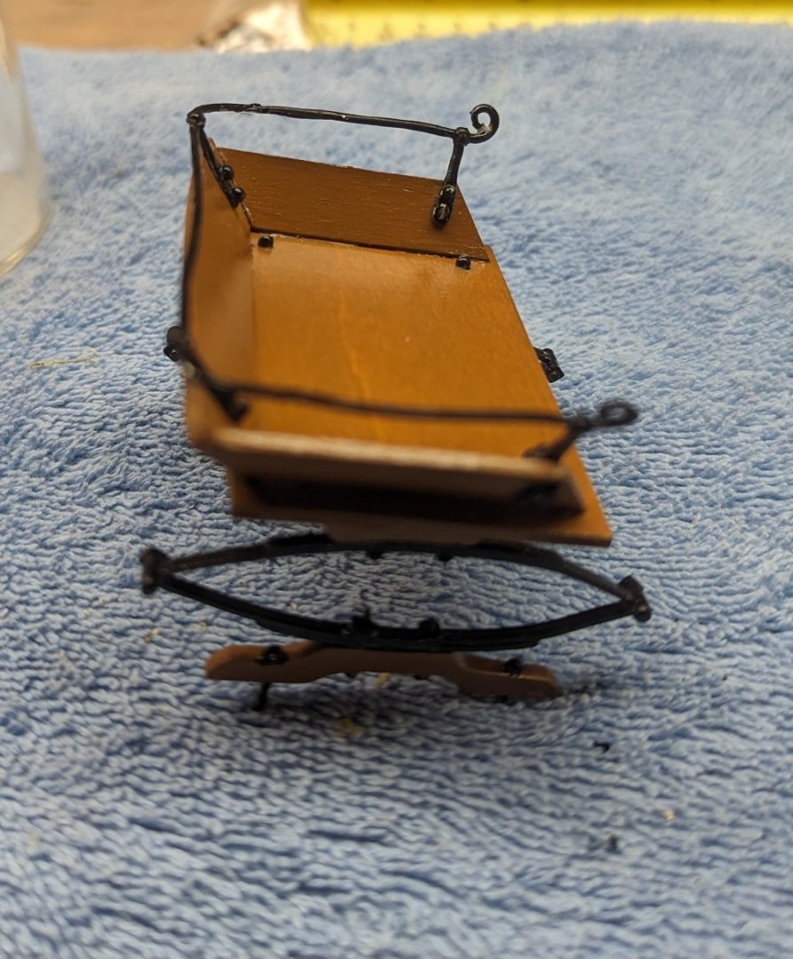
Moving on the the Reach Assembly. Do to my limited skill, this section was about a clear a mud as to the process. I am embarrassed to admit how many times I read this section and and studied the plans before I figured it out how all the parts went together. And even then, I did not follow the process. Instructions seem to indicate to build the reach Assembly on the cart one piece at a time. To me there are just too many really small parts that need to be (shall we say) "adjusted" to get to fit together as part of this assembly. I found it easier to build the reach assembly outside the cart and then just insert it into the correct position on the cart.
What makes the process confusing is that there are a number of parts that all have to come together just right in order for all the bolts to line up. Since we are dealing with the bottom of the cart there is one picture of the cart inverted in the instruction manual and there there is the one diagram of the cart that is not inverted. Between the two pictures it is really easy to get confused as to what you are dealing with. In all fairness to the instructions I guess they did a pretty good job describing the process, just that it was hard to understand the process with only these two pictures to go on. A few more pictures of this process would be really helpful.
Starting to build the reach plates..
On the lower reach plate there are two holes that need to be drilled out.

Final reach assemble ready to be inserted into the front spring assembly.
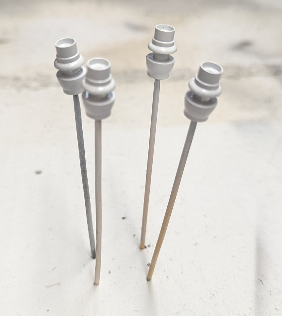
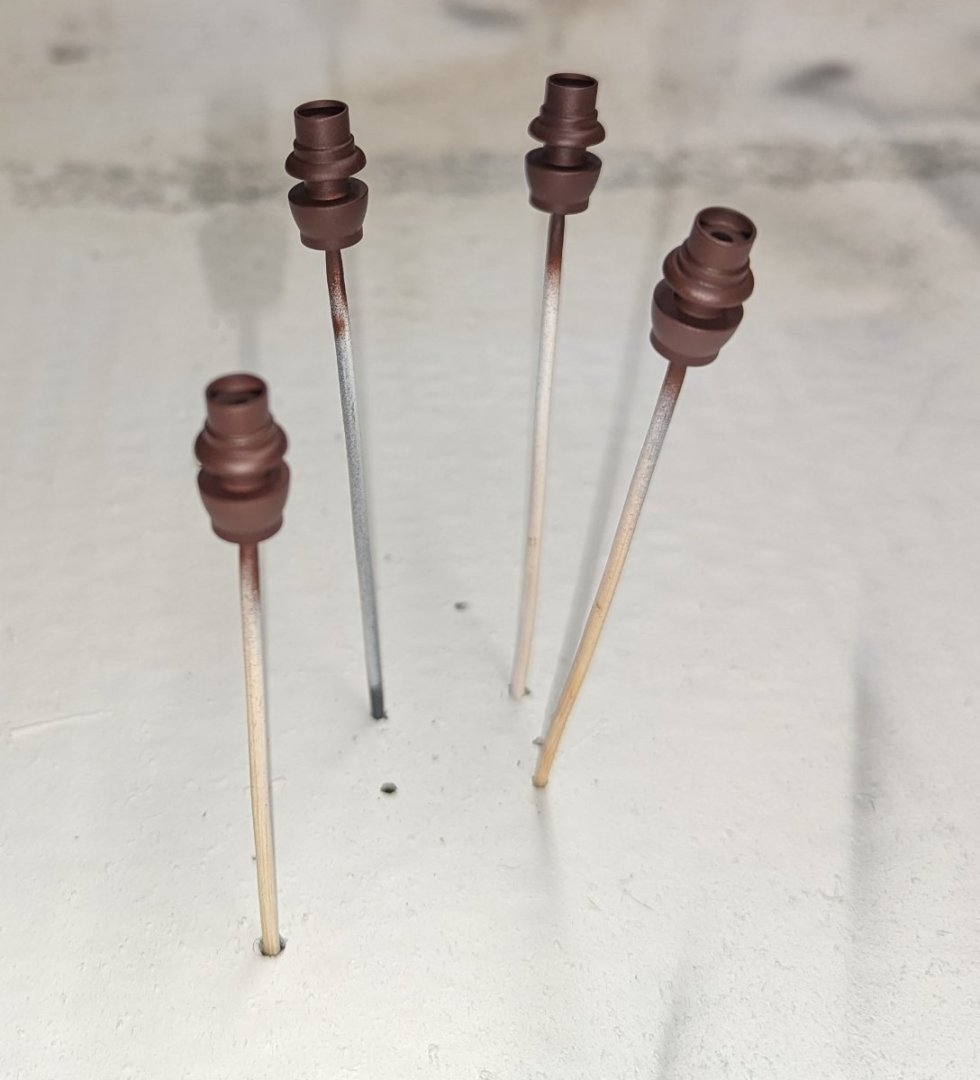
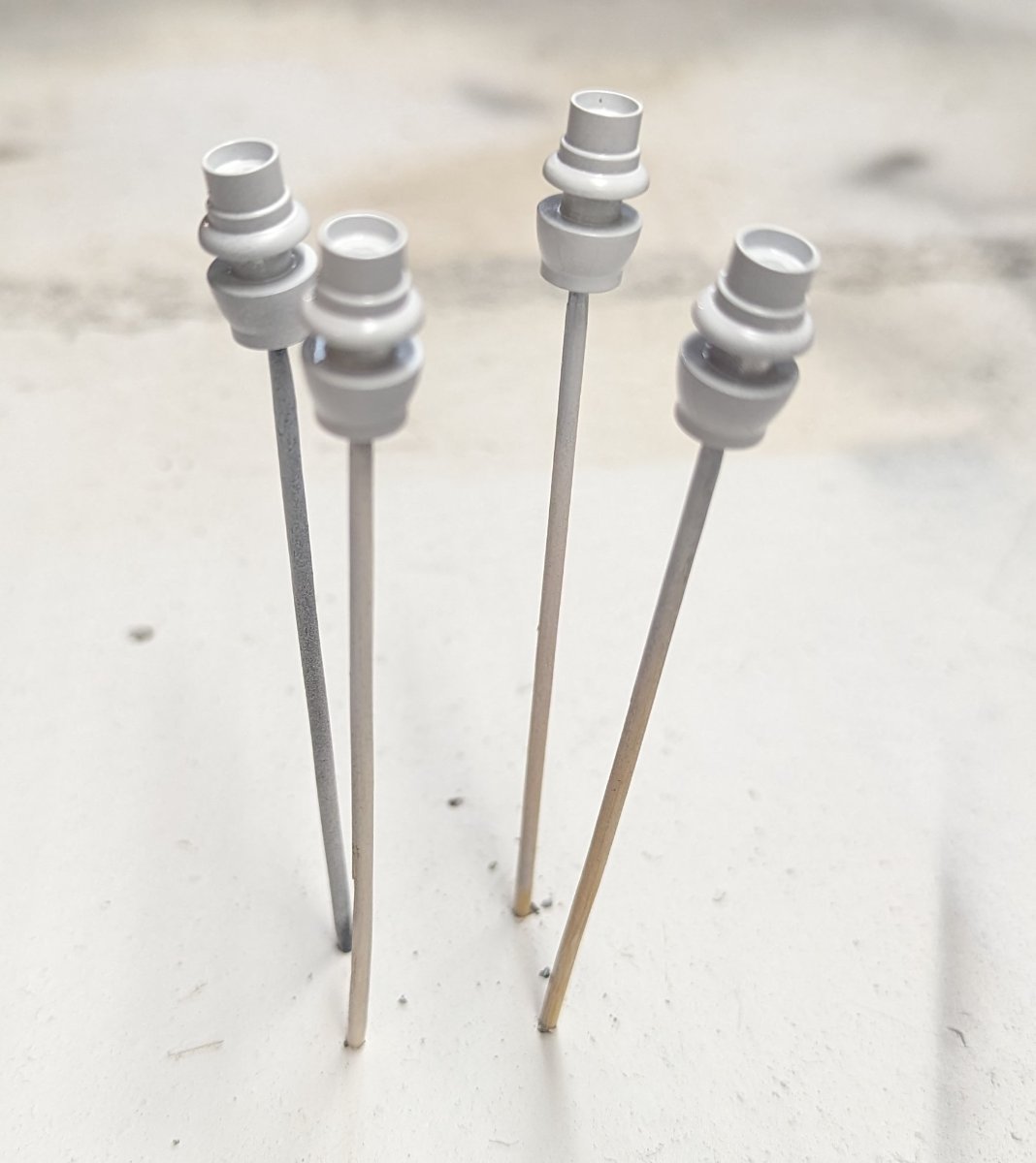
While working on the Reach Assembly I started priming and painting the wheel hubs
-
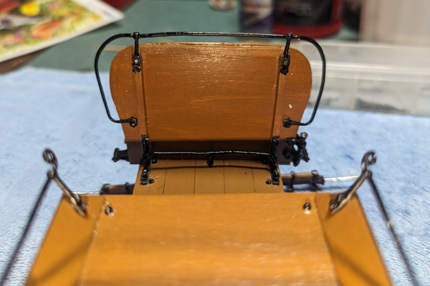
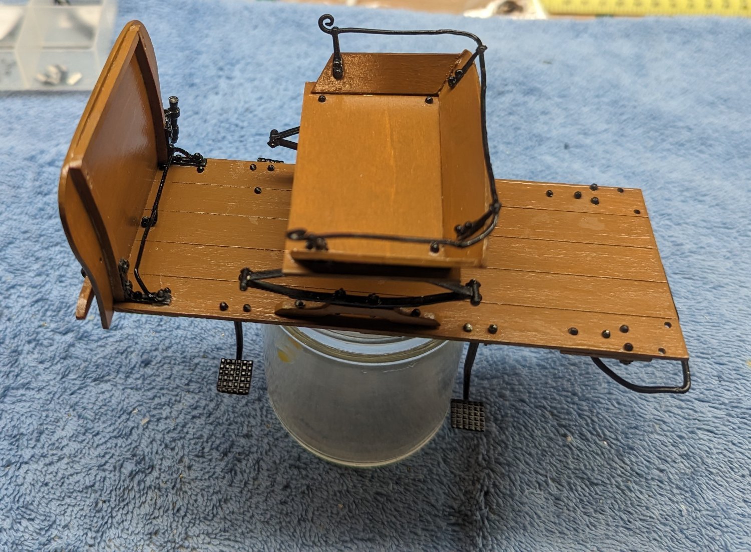
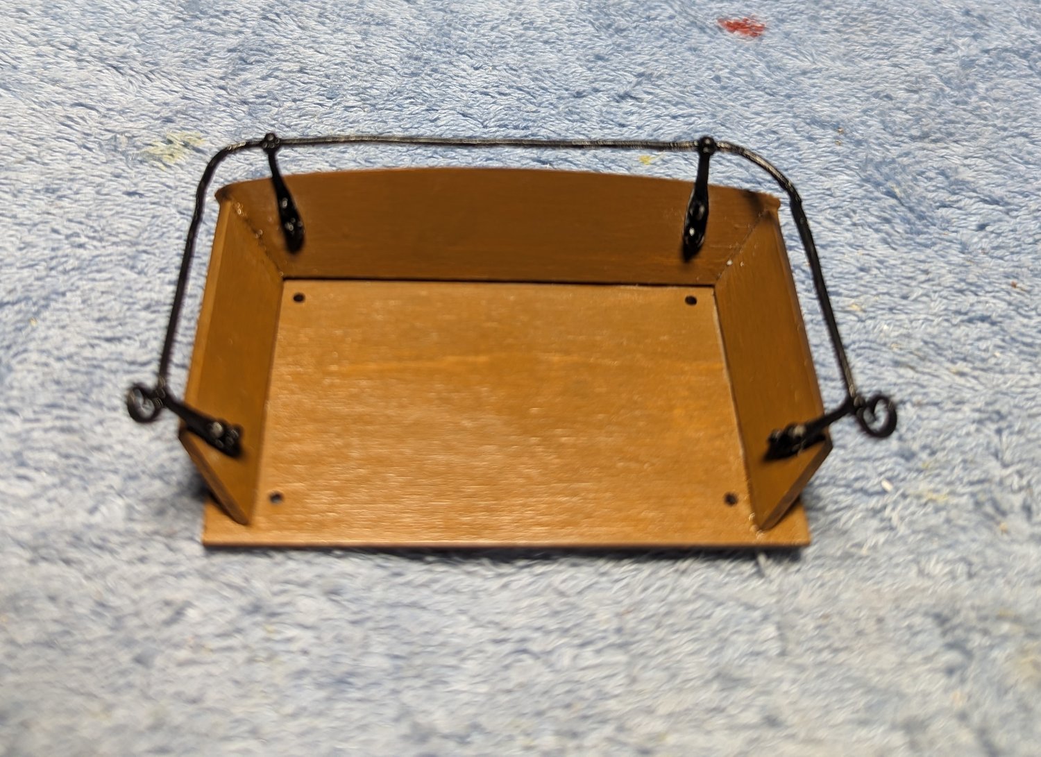
Began to assemble the seat... No real issues here other than be sure to drill you holes straight or (as mentioned before) you will have an issue with room enough to apply the nuts on the bolts.
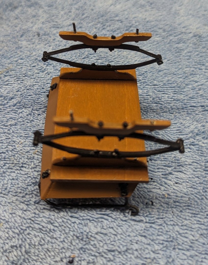
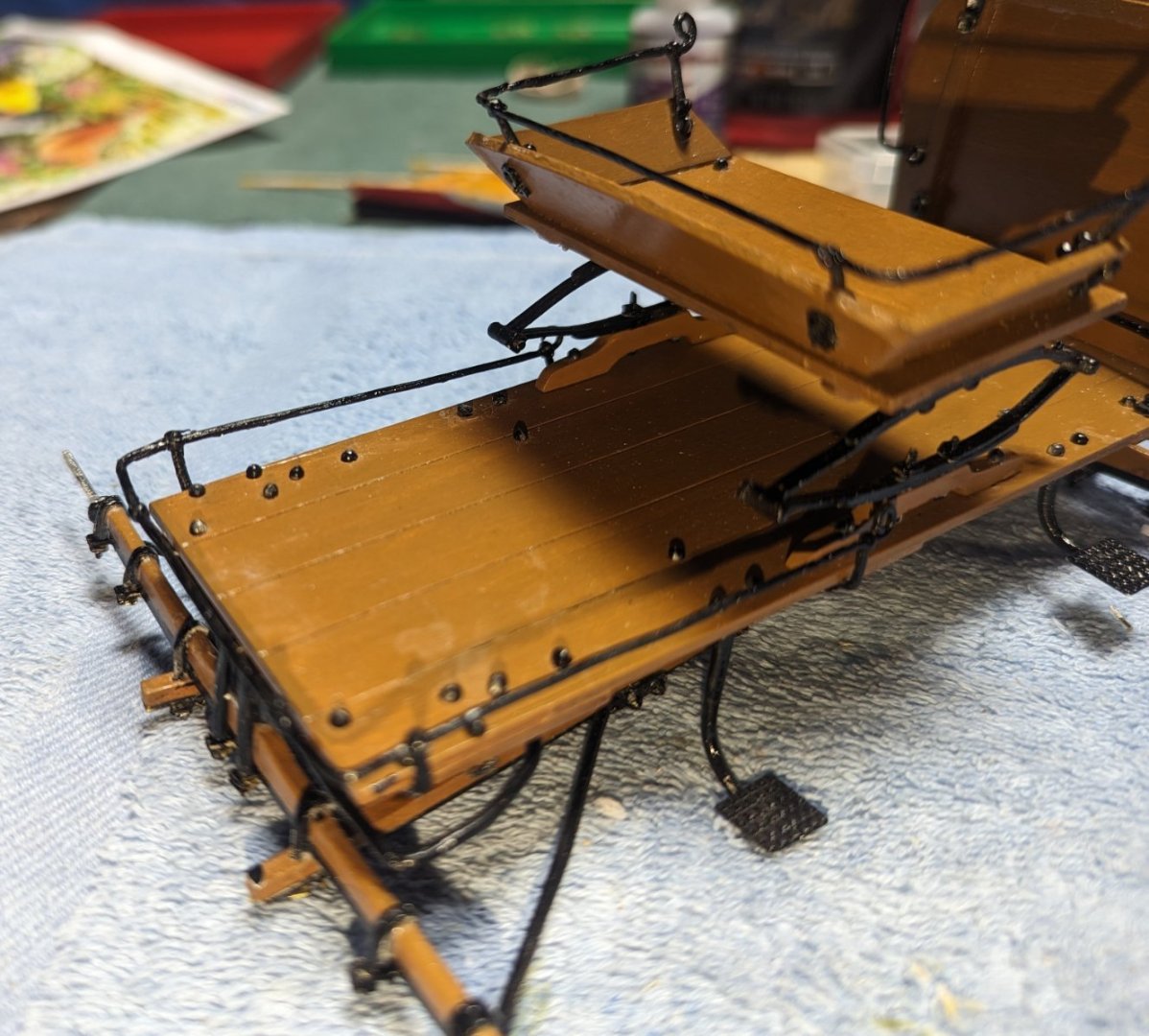
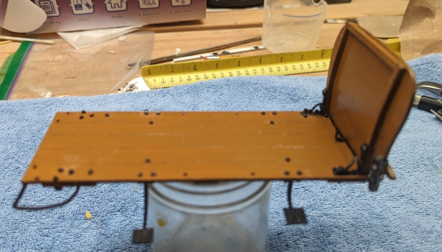
And just to see how it will look I dry fitted it on the the chassis. It was then removed as it it too early to glue the seat to the chassis.


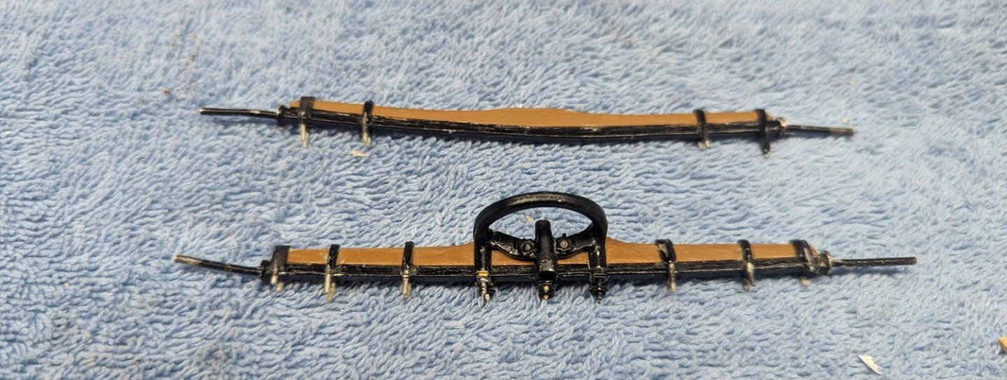
Went on to add the front and rear steps and the rear spring.
Rear spring took some fiddling to get it into the correct shape. Finally decided the best way to do it was to secure both feet to a solid surface. From there it was relatively easy to adjust the two springs. Once again I learned painting the Britannia before it has it's final shape is a waste of time. You just have to repaint it again.
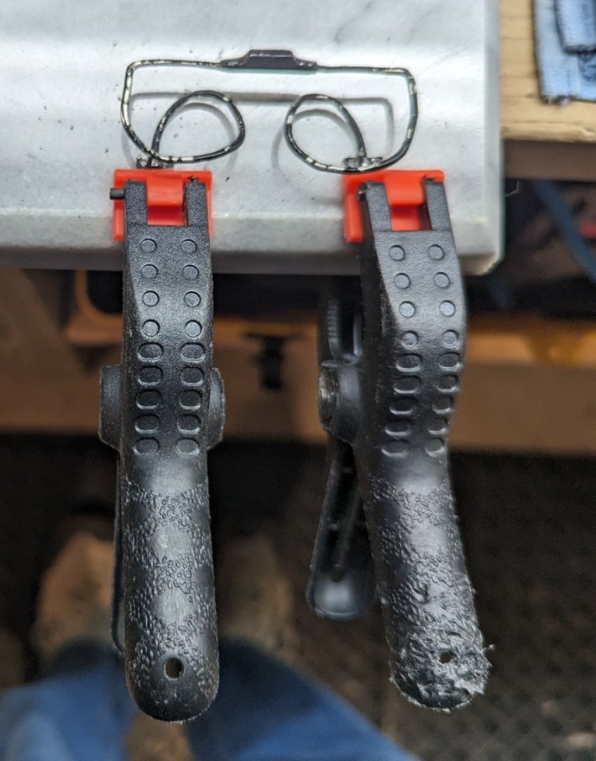
The end result. The spring on the left is better than it looks in the picture. Not sure why it looks so out of shape

-
The kit is supplied with various size bolts, the smallest ones are 3/16" and 1/4". They come attached to a single pieces of metal and need to be cut off (as shown below). The problem is they are way too short. They are supposed to be long enough to go through the designated part and be long enough to put a nut on the other end. As I started out every place I put a 3/16" bolt it was not long enough to reach the nut. In many cases I had to just glue the nut over where the bolt was supposed to extend. I finally got smart (way too late) and just started using the 1/4" nuts every place it called for a 3/16" nut. Problem is, I will run out of 1/4" nuts. Since this was Model Expo (and they easily replace missing or broken parts), yesterday I requested extra 1/4" nuts. They should show up in the next week or so.
If you are starting out on this model, I would suggest right away asking Model Expo for extra 1/4" nuts.. you will be glad you did
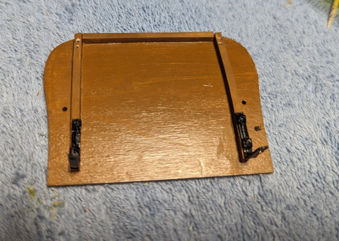
Started on the seat. Main "gotcha" here (and it got me) is with drilling the holes for the seat rail. You drill from the inside out. That part is easy, but the holes are so close together, that unless you drill the hole exactly parallel they there will not be enough room on the outside to put the two nuts.
Here is the seat from the inside

And from the outside. If the holes are drilled correctly the nuts should be next to each other. But if they are off at all, there will not be enough room for the two nuts. In my case, since I did not realize this until I drilled the holes, about all I could do was fill off the bolts and just glue on the nuts, like the bolts came all they way through. Seems that one nut needs a little touch up paint
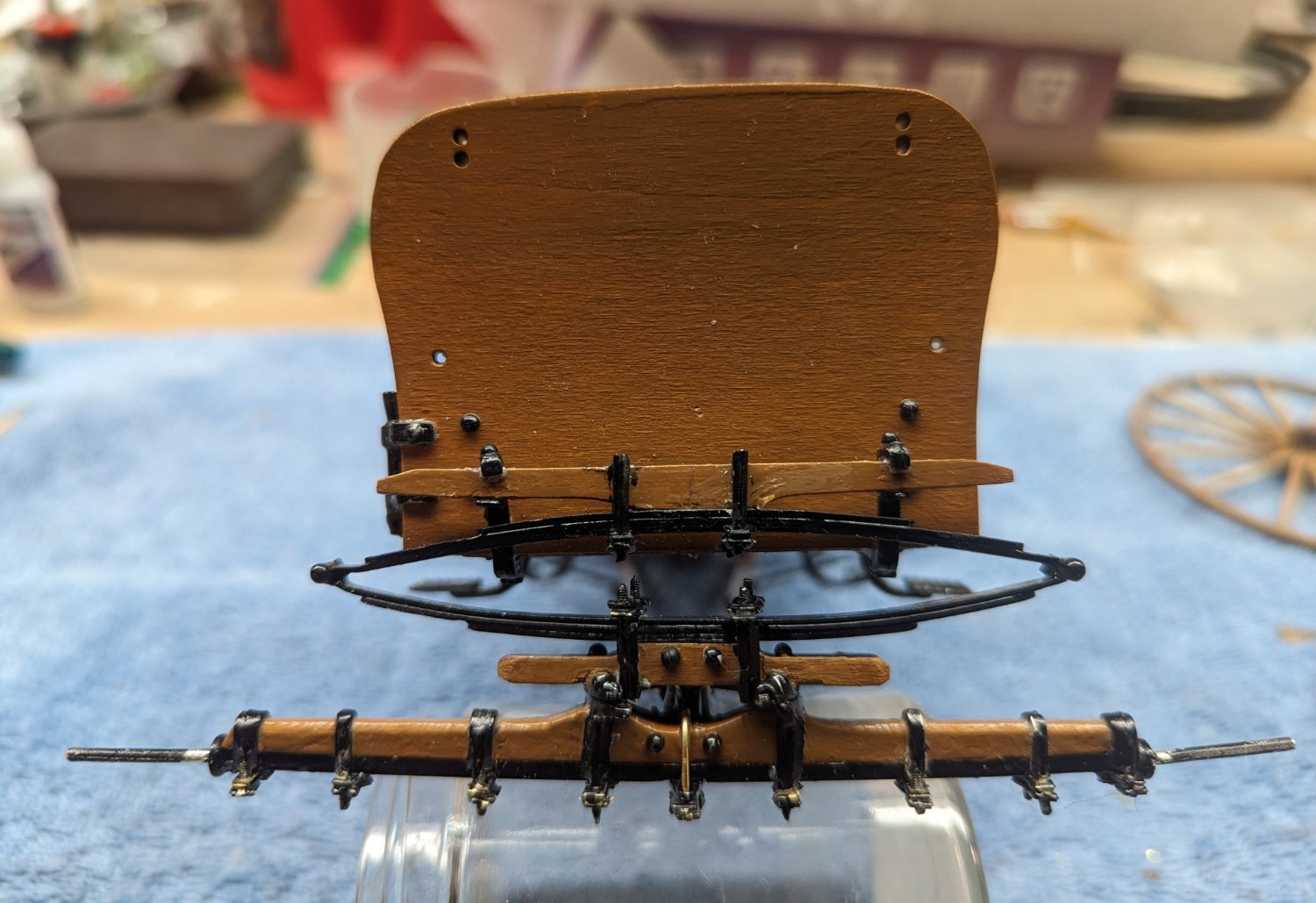
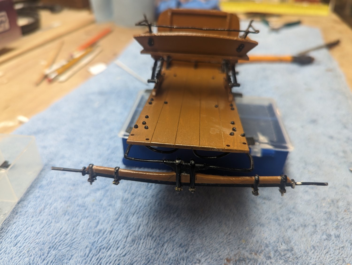
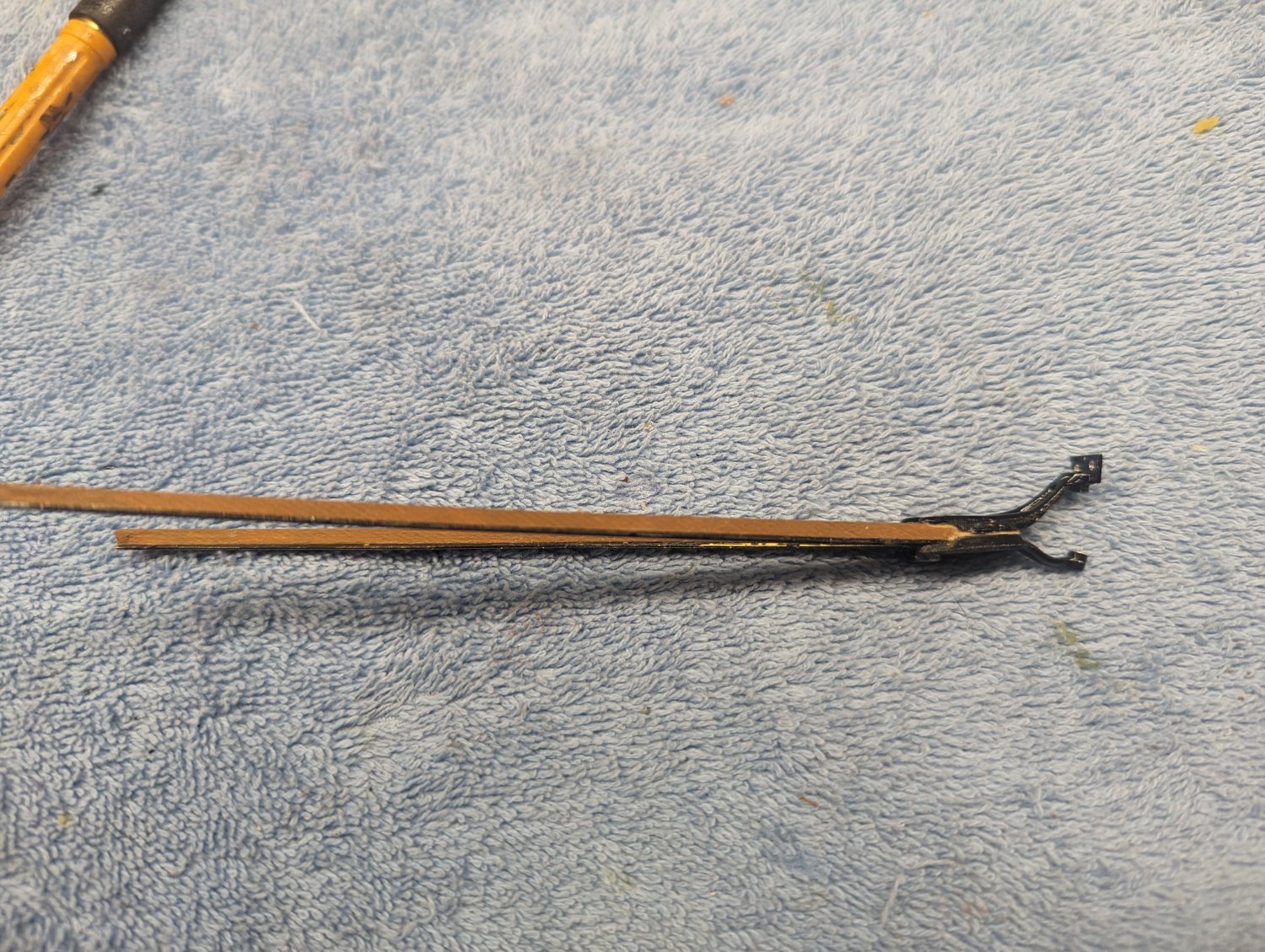
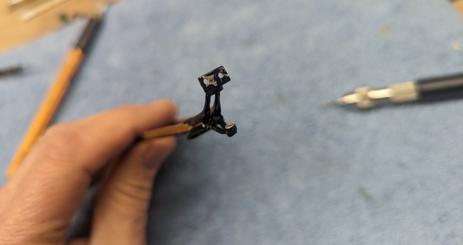
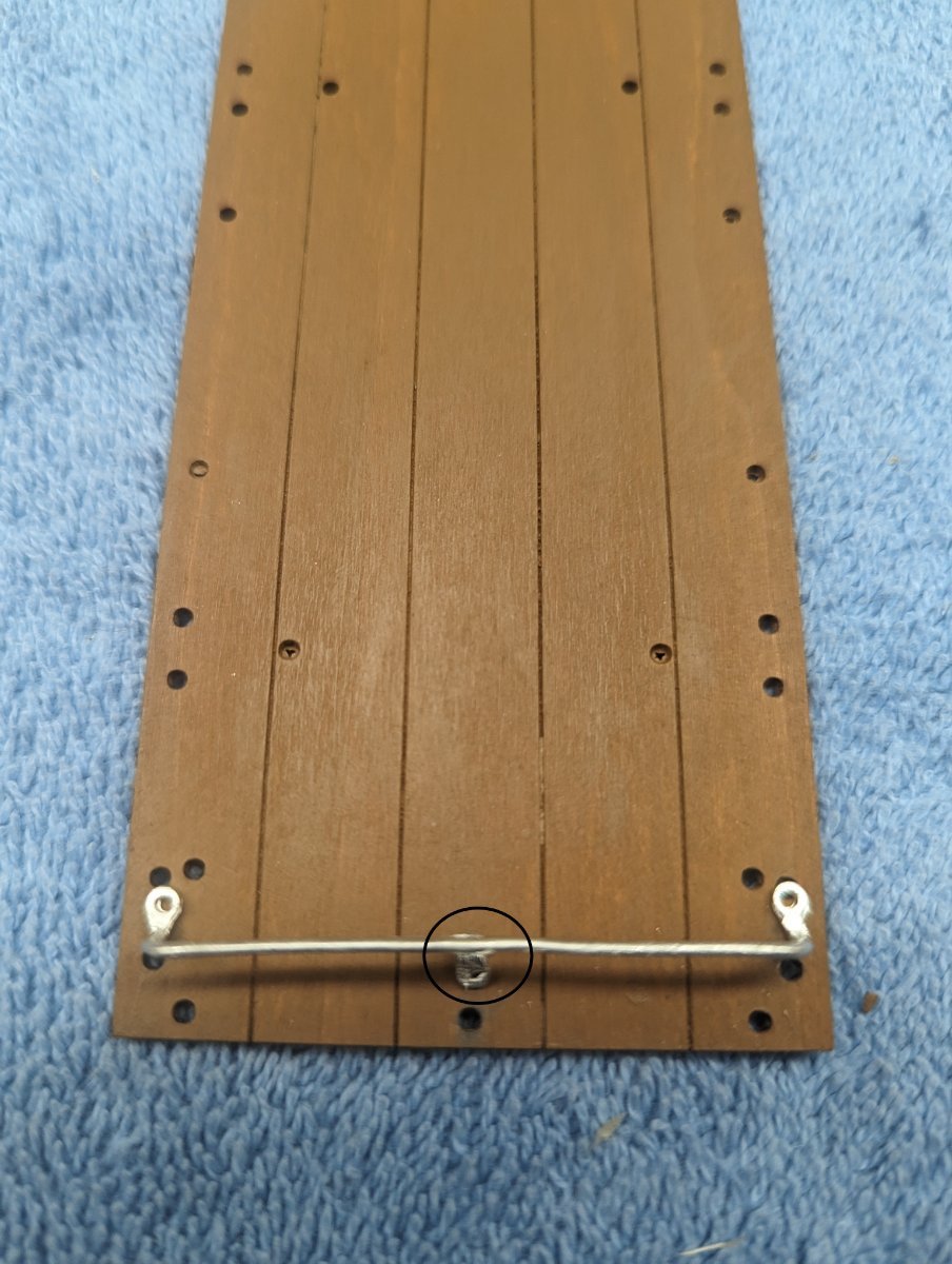
Bending the apron wood and attaching the right angle bolts is pretty straight forward
Front side
Back side
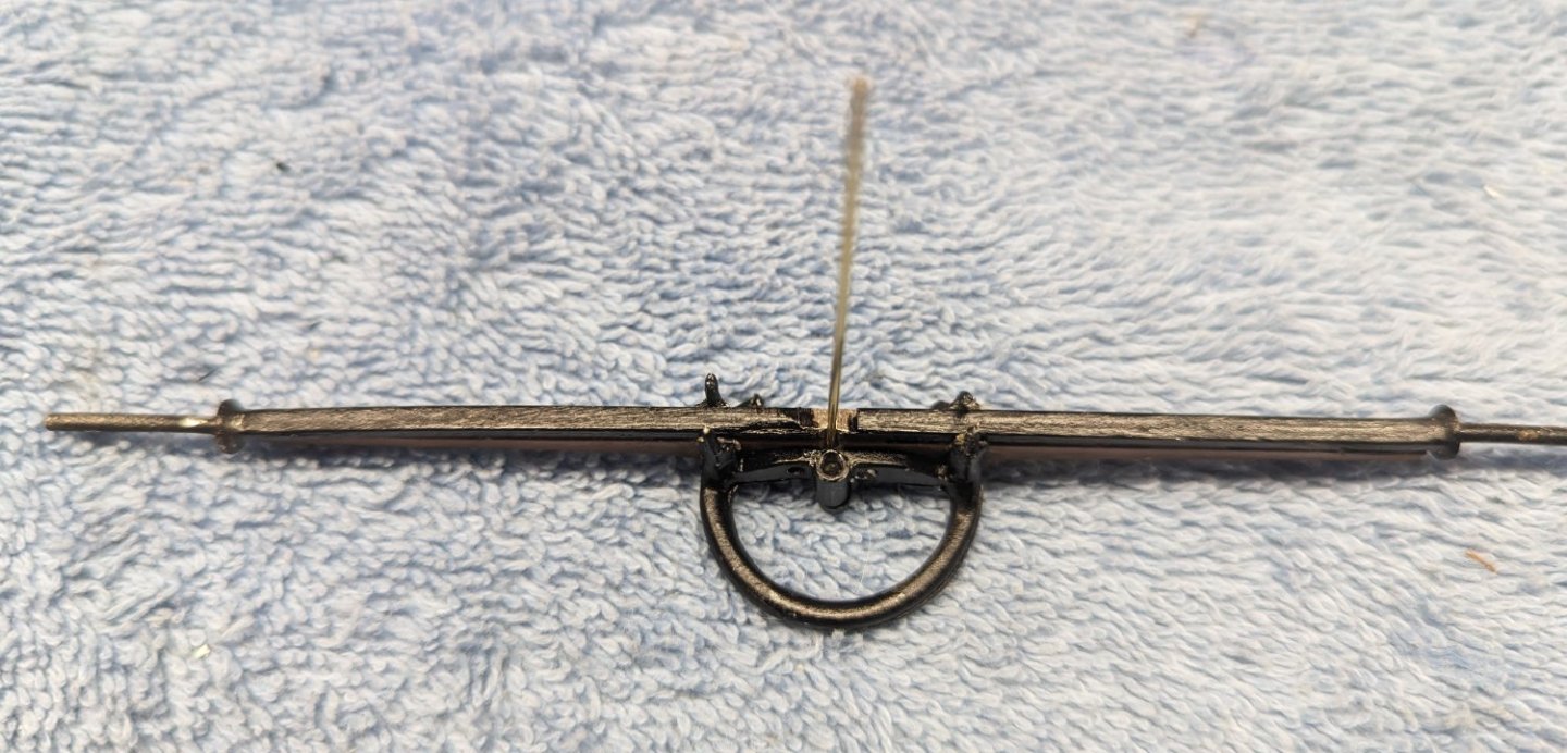
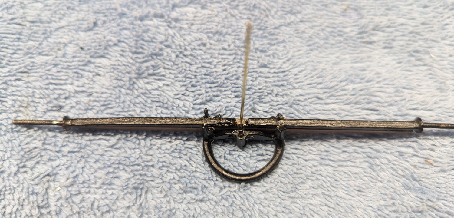
Front spring bar attached to the chassis is pretty straight forward
Underside view

Top view

-
Jan,
Interesting site....He is truly dedicated to his craft. I admire him and his work.
- Old Collingwood and Canute
-
2
-
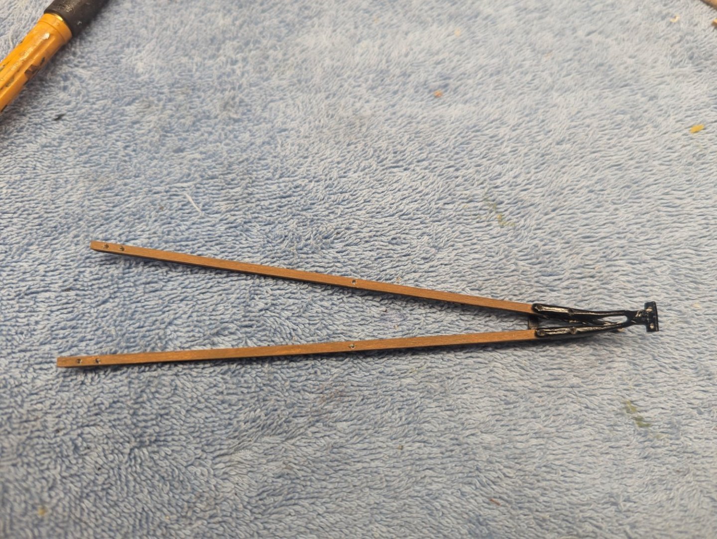
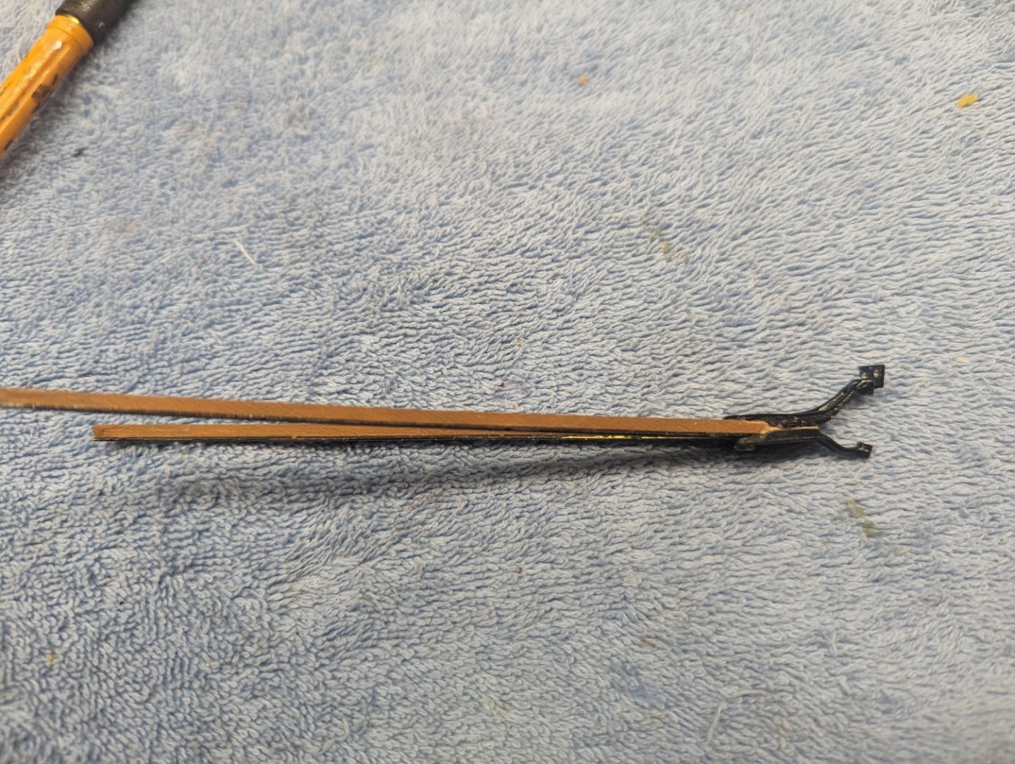
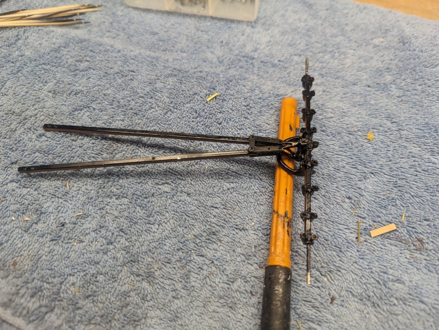
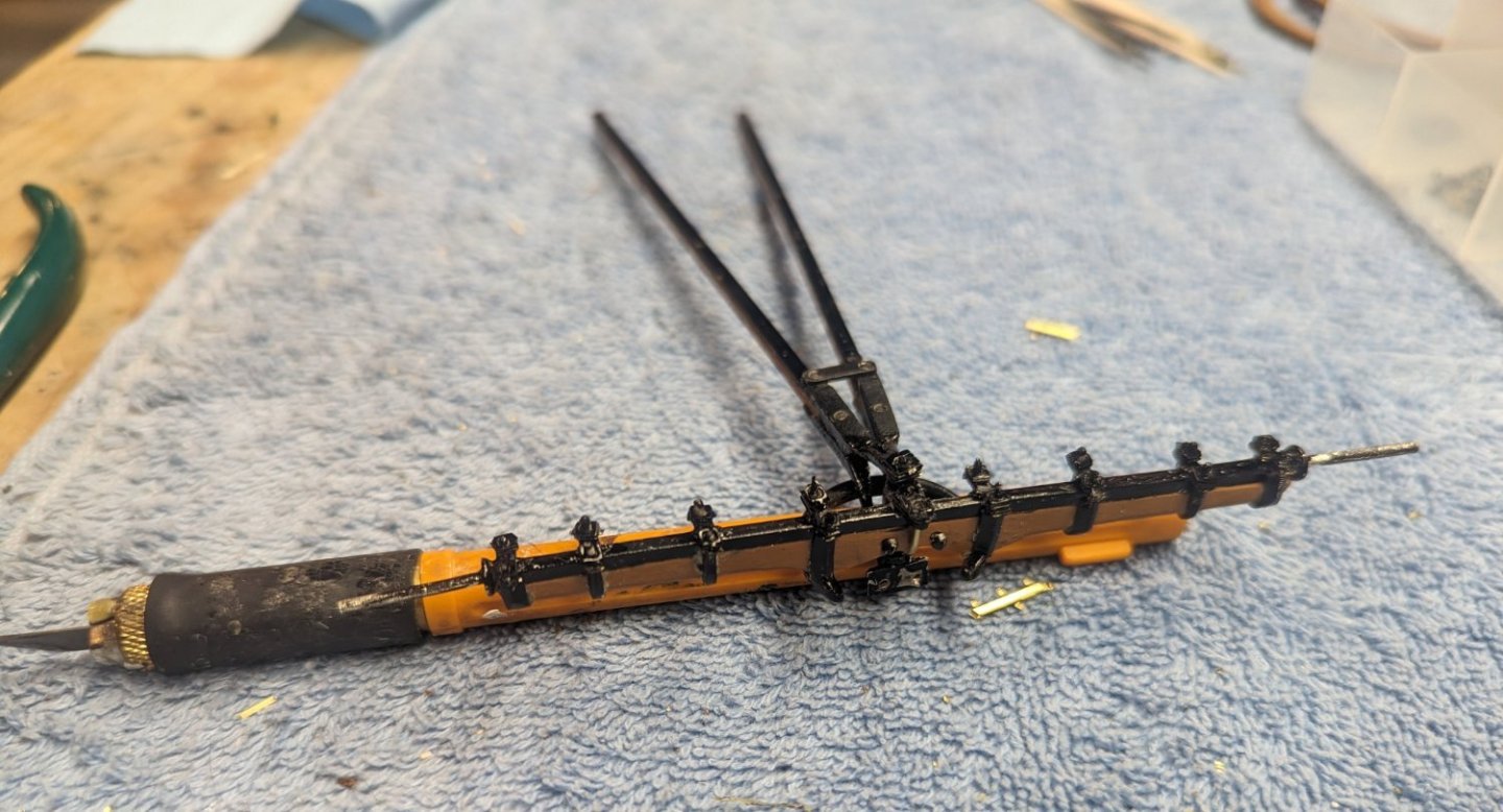
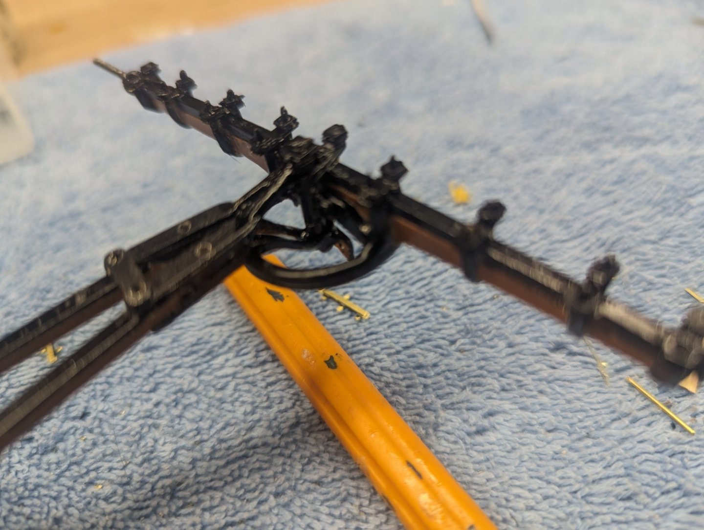
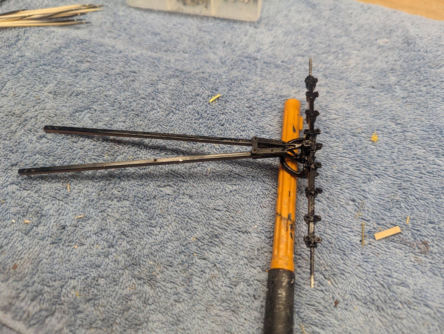
After a lot of Britannia cleanup I decided to prime/paint all the metal parts. Took some time to get this point. Almost every hole on each Britannia part had to be reamed out with the #55 drill bit. In addition many of the skinny parts had to be re-shaped to be close to the final shape they would take on the model. Below starts the primming
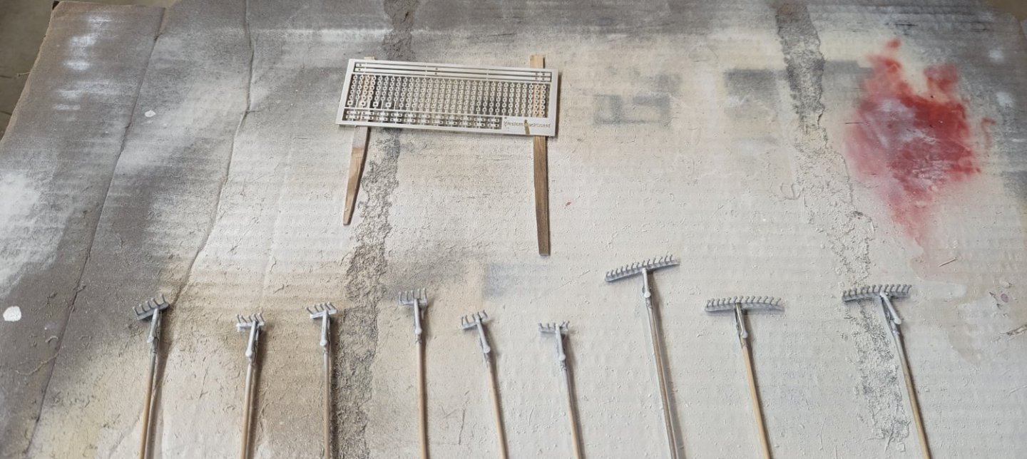
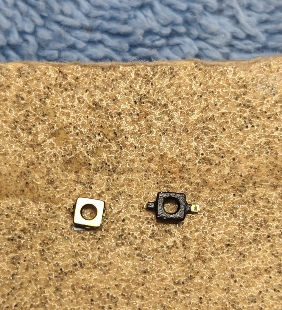
And after the final coat of black. At the time I felt the best way to deal with all the small nuts on the brass was to prime/paint them in place and then separate them. That turned out to be a waste of time. Priming/painting went great, the problem is when you remove the nuts from the brass there are a couple little "tags" on each nut where it was attached to the next nut. In the process of filing off the "tags", all the paint came off. In the future I would suggest, first separating each nut, file the smooth, and then mount each on a toothpick for painting. That way after painting not additional handling is required prior to putting them on the model.
Below you can see one of the painted nuts cut from the brass. By the time you trim off the tabs, to look like the nut on the left, all the paint is gone. Thus the toothpick method mentioned above is best for these nuts
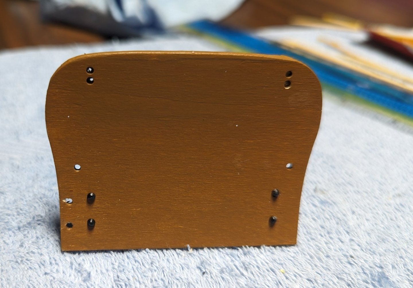
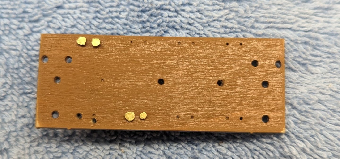
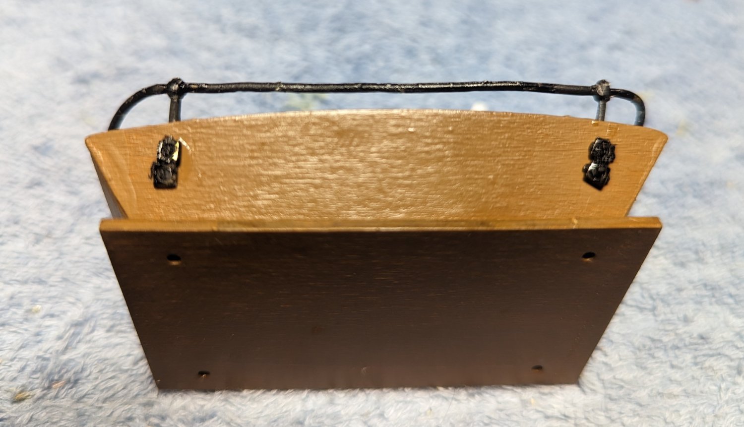
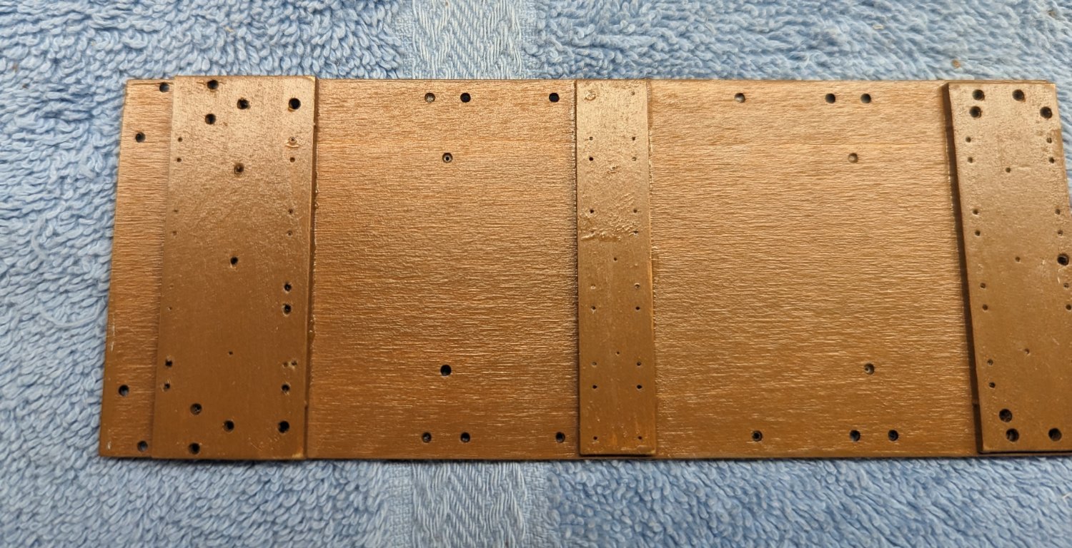
At this point comes my (shall we say) first "executive decision"... On the bottom side of the base there are 65+ little holes to where nails are to be inserted. Below you can see both the large and tiny holes.

Supplied nails are to be inserted into these tiny holes, cut off from the other side, to where only the nail heads would show on the bottom of the buckboard. These nail heads will only be seen if one picks up the buckboard and looks underneath. As you can see below, the supplied nails and no where near consistent in size. I put a few in and they looked terrible. I just could not see putting in 65+ of these nails that would never be seen. Not only are they ugly, but some if the tiny holes are so close to the edge, I can easily see splitting the wood. To me it was just not worth all the pain for what would be an ugly mess. Thus I choose to skip these nails.
If one really wanted to build the model correctly, I would suggest ordering some good nails from Model Motorcars. They are somewhat expensive, but they are high quality nails and would look much better than what I have going here.
Even from the side view, the heads just do not look right

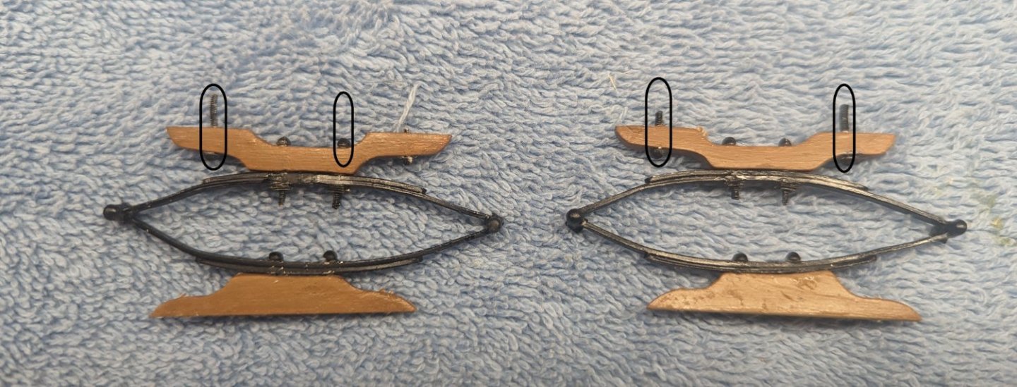
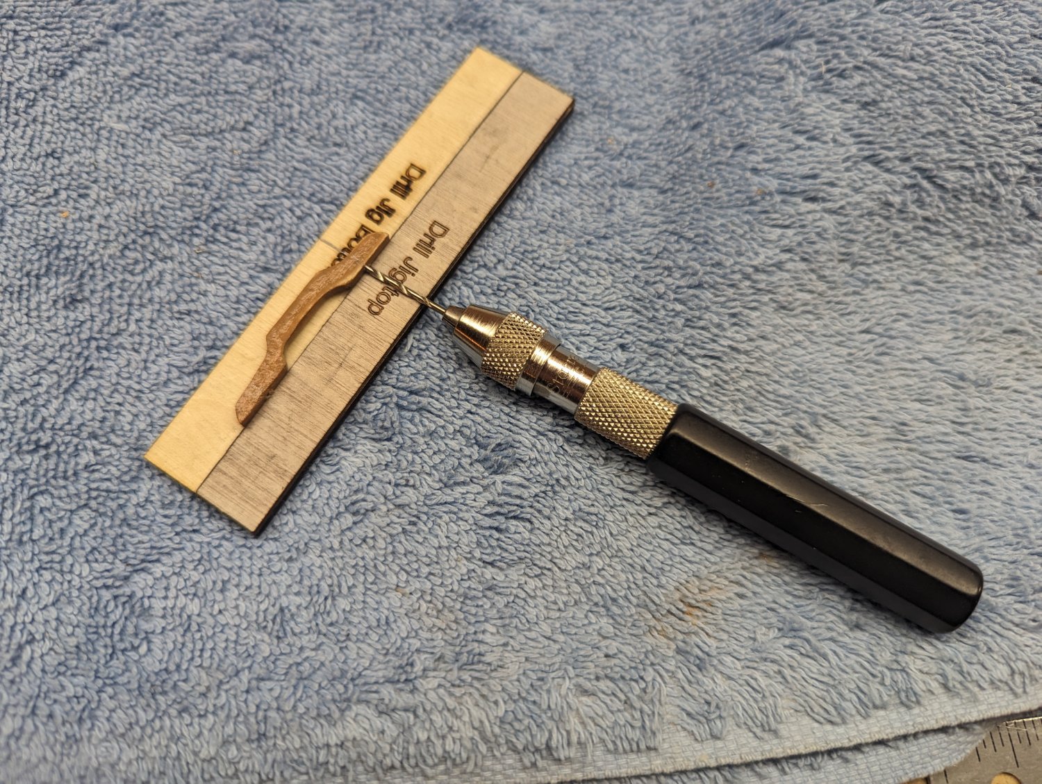
Moving on to building the seat and platform brackets. Instructions call to build a simple jig to assist in drilling the holes in the seat and platform bracket.
At first I was a little Leary of this jig, but it turned out to be simple and every accurate.

The only issue with the seat and platform brackets is the instructions call to insert the 1/4" and 3/16" bolts (circled below) after gluing the seat and platform brackets to the seat springs. Problem is there is not enough room between the spring and the bracket to insert the bolts. Thus you have to bend the Britannia springs out of shape, insert the bolts, and then bend the spring back into shape. Bending these Britannia springs (without breaking them) is it's own form of excitement. I would suggest gluing in the bolts before attaching the seat and platform brackets to the springs
- Diver, Ryland Craze, Jack12477 and 8 others
-
11
-
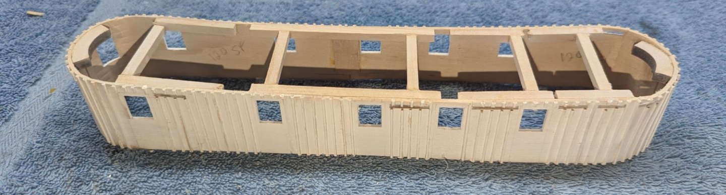
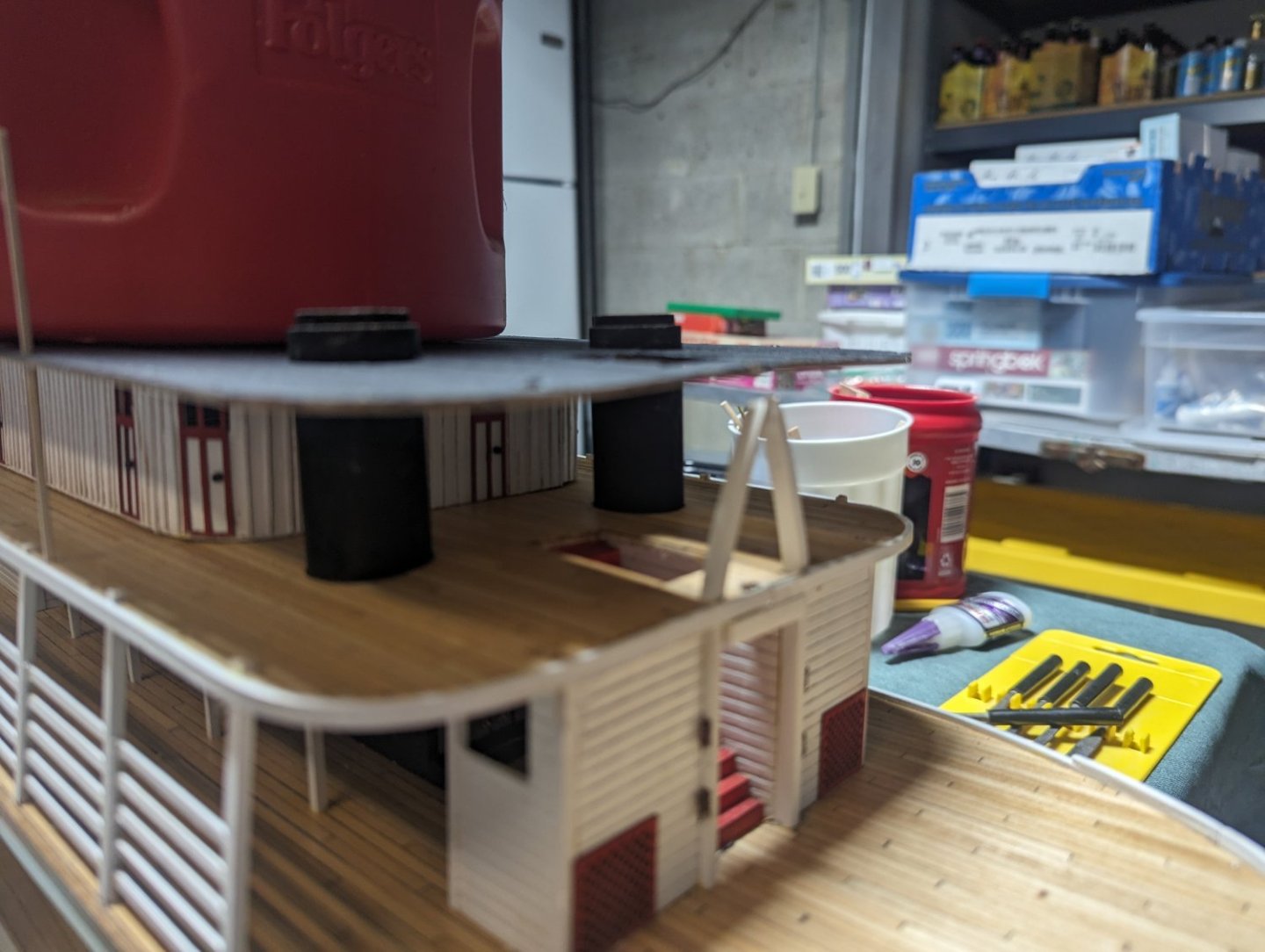
Not much to really report today...... Started inserting the boiler deck stationaries. As Cathead mentioned on previous post, putting a square stick into a round hole works out pretty well. Just the smallest touch of glue and the stationary easily slides into place. 1/4" above the huricane deck was easily maintained with a 1/4" piece of wood as a guide
As you can see toward the middle of the boat the hurricane deck flared up a bit on the overhang and to be (shall we say) persuaded with some jigs to keep the proper curve. Same jigs used between the main deck and the boiler deck were modified and did the job well. Once glue dried, the hurricane deck was in the correct position.
Closer look at the stationaries... No big deal.
-
Cathead,
I agree with what you are saying... As I tried to dry fit some of the square stationaries into the round holes, those little extra bits of tape really help hold the stationary in place.
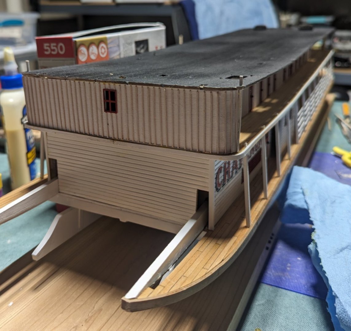
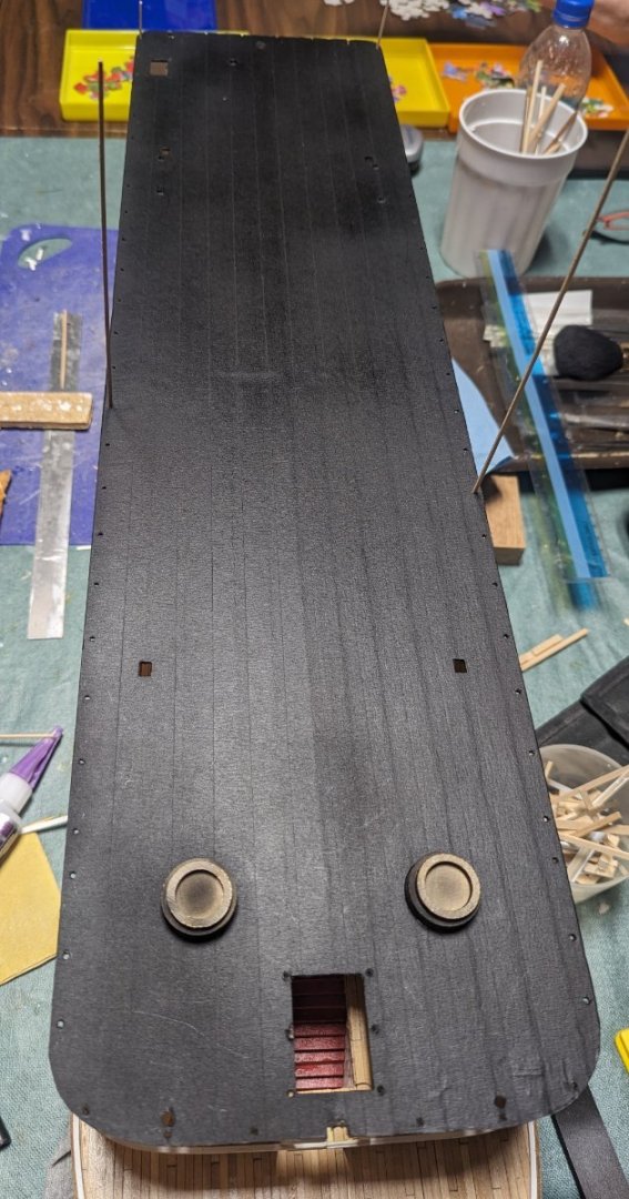
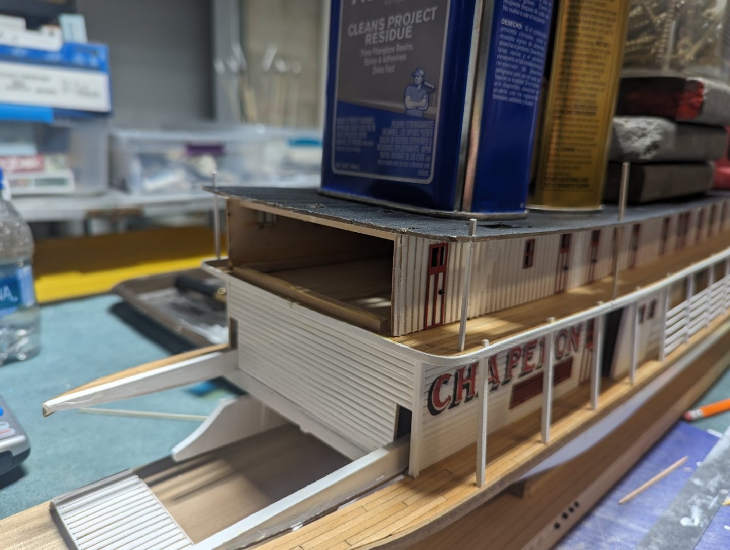
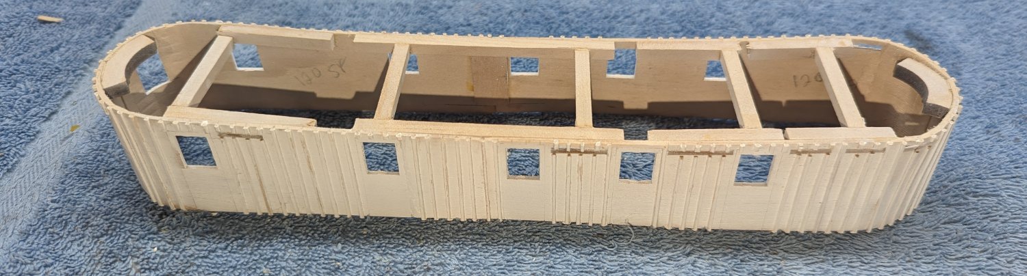
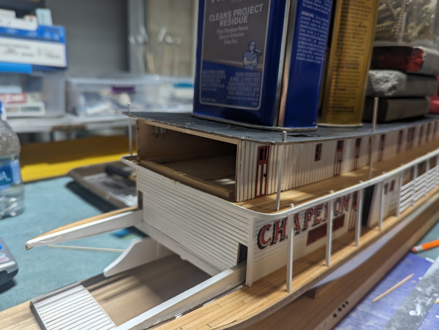
With the hurricane deck glued down it was a simple thing to slightly lift up the aft portion of the deck and slip in back wall.
For those that follow in the future with the chaperon... when building that back wall, the jig provided is good in helping with the curve, but not that accurate. Even my "juice can" method (mentioned earlier) is rough... No matter how you bend the walls, the most crucial point, and it really should emphasized in the instructions, is that that back wall curves need to match the last holes in the boiler deck floor. Otherwise the wall will not match up to the last stationaries and will just looks off. Had I know that fact when I was bending the walls, I would have insured the final bends matched the last stationary holes. In my case even with a little fiddling, the wall does not match up exactly to that last stationaries. At this point I think I am going to leave it as is..... But don't make the same mistake. This could have been better had I know the exact bend was critical
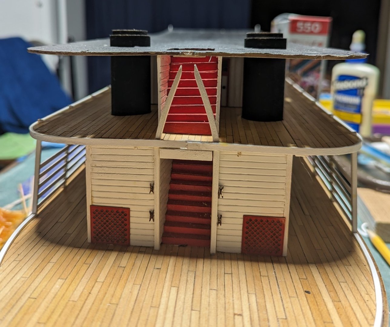
As for the bow and the forward stairs, as mentioned earlier, save yourself a lot of grief and do not mount the stairs prior to the hurricane deck as stated in the instructions. Once the hurricane deck is down it is easy to slip it into place. No way could I have glued those stairs in prior to the hurricane deck as expect them to line up exactly
-
Brian,
That is a good comment.... And it would be like me to forget that. But fortunately this time I did not. Before I masked the sky light I located where the Texas cabin would be located and laid down the wood foundation to support the walls. Then I laid down the masking tape and painted around where the Texas cabin would be formed....
I will say, there is one issue with the masking tape method.. On the Boiler deck the stationary holes around the edge are square (to accept the 1/16" stationaries). But unless you have some sort to square drill (and I do not), to free up the holes (covered by tape) you have to drill or poke them out,,,, and they end up more or less round. But when I comes time to put in the stationaries, square wood is close to round, and with a hold that small, the square wood fills up the hole and it is not noticed.

-
Earlier I said I was not going to start this build until end of October....and that is mostly true,,, But just could not help myself. I just had to open the box and do a few initial things.
Started out by cleaning up the char marks and staining the most of the wood components. Only wooden spokes and wheels are still in the box. There are so many spokes, I figured by the time I got the that part of the build I would have lost some of the spokes.
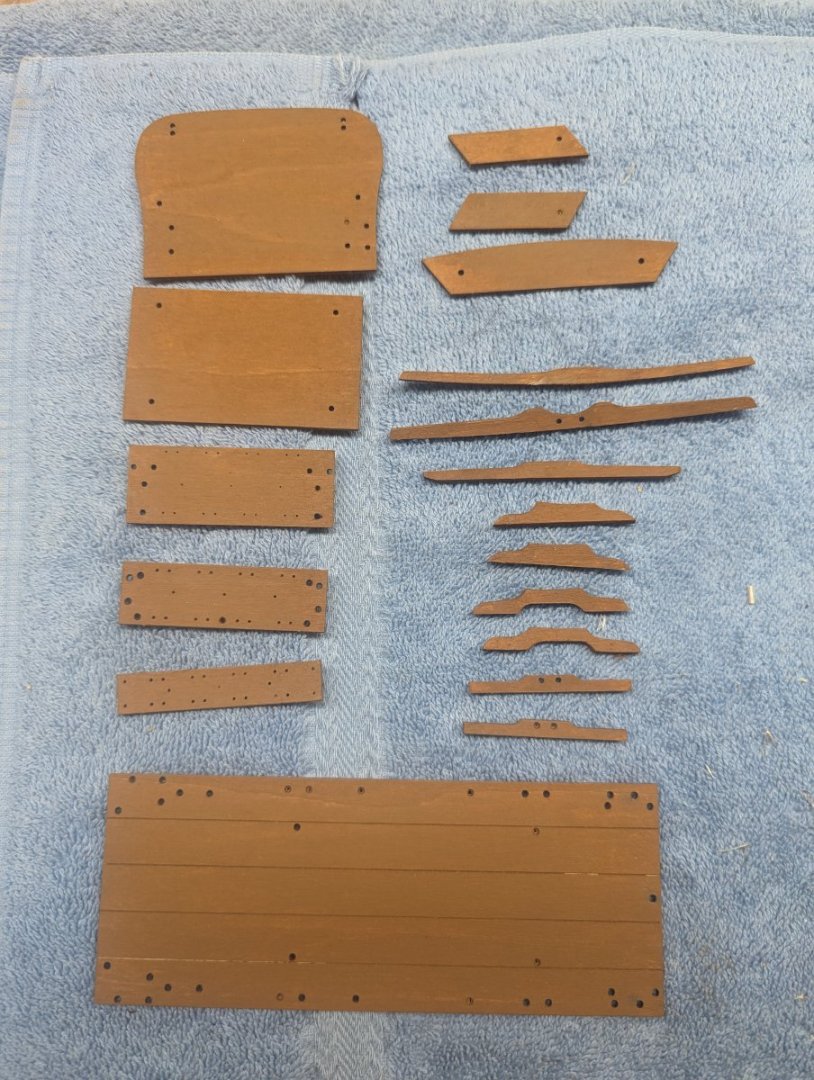
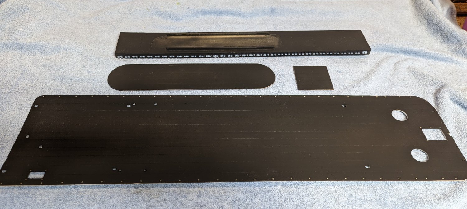
Here are the non-wheel wooden parts
Started cleaning up the Britannia metal parts. As mentioned earlier this will be the (shall we say) "interesting" part of the build. Anyone who has worked with Britannia knows what I am about to say... UGH..
As with most Britannia parts, the metal is soft and does not come easily out of the mold when formed at the factory. As such, many of the parts are mis-shaped and/or have rough edges that need to be cleaned up. I would say with this model the Britannia is as you would expect... no better and no worse than any other Britannia parts on other models.
Since many of the parts are mis-shaped, I would suggest as you clean them up, to look on the plans and try to bend the part into (more or less) the correct shape before you prime and paint it To me, doing all the bending after the part is painted, could tend to knock off some paint and require touch-up.
I will say that some of these Britannia parts will be somewhat of a challenge. Most of the Britannia parts are to be "simulated" bolted to the wood chassis. As you can see the chassis clearly shows where the parts will be placed. And the parts have the holes drilled into them. Problem is, being Britannia parts, many of the holes in the parts are mis-shaped and/or or never formed properly in the mold, In the part below I have positioned it close to where it will eventfully be placed. The part (circled below) shows both outer holes pretty well formed, but the circled part hole is complexly filled in with metal.
Normally drilling out the hole would not be a problem, but the mis-shaped part is only a little bigger than the hole I need to drill. I give that hole a try, but I have a feeling the part will break, and I will have to "simulate" a bolt running through it. In the end no one will be able to tell the difference but it would have been nice to have the part large enough to drill the correct hole size. I won't show other parts with this same issue, as you get the idea, but it looks like there are a number of parts that will need their holes drilled. I just we just chalk it up to "fun with Britannia" 🙂

-
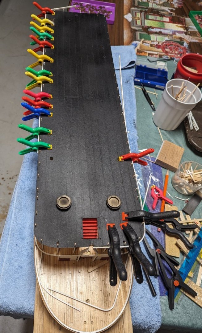
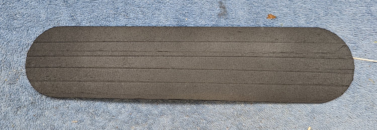
Onward and upward... At long last the hurricane deck is finally ready to glue. All holes have been enlarged and ready to accept the corresponding parts that come next.
As for the simulated tar paper strips, I think the masking tape idea worked out OK. As indicated earlier, at my skill level I do not think I could have pulled off silk span or tissue paper methods.
A couple of points for those of us less skilled,,,,
The instructions call to glue the forward stairs, from the boiler deck to the hurricane deck before gluing down the hurricane deck. In my opinion, no way would I be able to pull that off and have the stairs align properly with the hurricane deck. If those stairs were glued down prior to the hurricane deck, with all the alignment (shall we say) "fun" lining up the hurricane deck with the stationaries, it would be too much to hope to assume those stairs would be in the correct position. Instead, since the hurricane deck overhangs the boiler deck, will be an easy effort to just slip in the forward stairs after the hurricane deck is glued down and before the stationaries are inserted.
Below is a show showing plenty of room to insert the stairs and secure them down to the proper size prior to the stationaries.
Same issue with the boiler deck back wall. Instructions call to glue down the back boiler deck wall when you glue down the boiler deck structure.
In the below picture, neither the back wall or hurricane deck have been glued down. As you can see, the edge of the back wall should align with the last stationery. In theory, if you were every accurate with the bending of this wall, it will align with the last stationaries. But if that bend was not exact (due to lack of skill of the builder), there will be an issue aligning with the last stationaries. Even if you bends were exact, after aligning the hurricane deck over the boiler deck, the back wall my not align with stationary. However, if you do not glue down the back wall until after the hurricane deck is aligned, then you can fudge a little to make the wall edges align with the last stationary. In my case there was fudging involved...
Again,,,, these last two issue are only for us less skilled builders 🙂
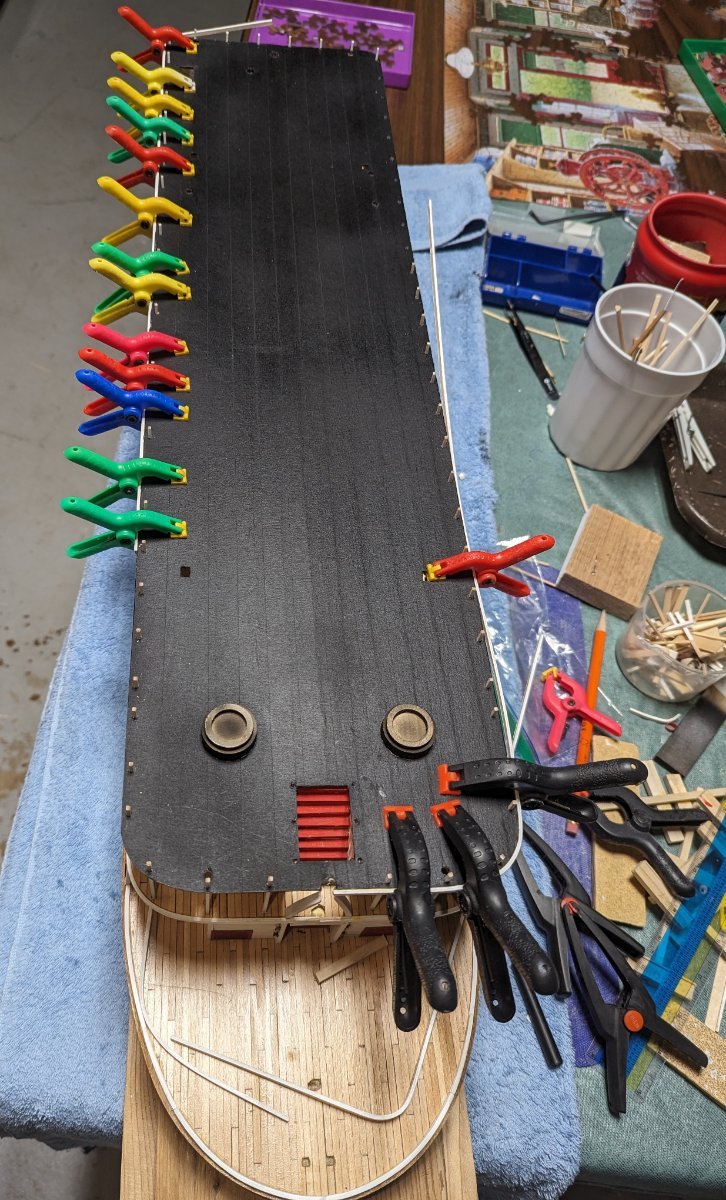
Here is a picture of the hurricane deck being glued down with back wall open. After the glue dries, the back wall will be inserted similar to the forward stairs mentioned earlier
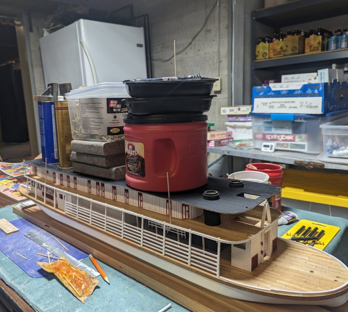
Time to glue and pile on the weight.. everything including the kitchen sink... That coffee can is filled with water to add a little more weight.
Hope is does not leak, or there will be a lot of tears,,,,
-
CDW..... Interesting story.... Thanks for sharing...
john
- mtaylor, Egilman, thibaultron and 3 others
-
6
-
Brian,,,,
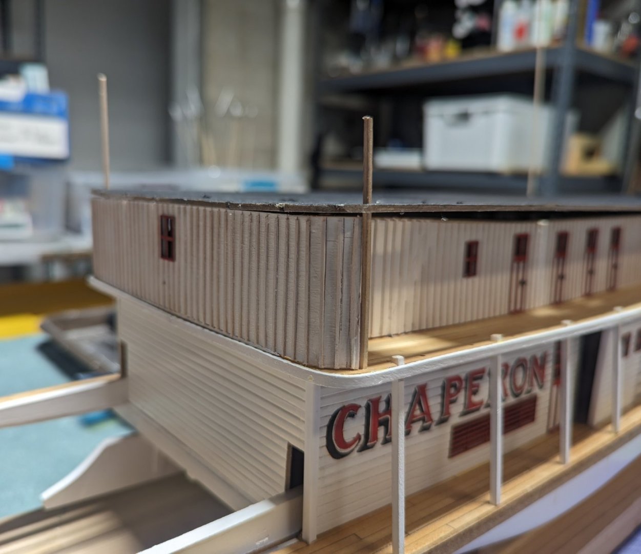
I mis-spoke..... You are so right,,,, Putting the bull rails up are nothing compared to the battens on the Boiler deck structure .... I have not had that (shall we say) "fun" with the Texas deck cabin walls yet.... Plan to have that "fun" next week.... At least there are not as many on the Texas deck cabin walls as the Boiler deck structure.
-
After working on several year long plus (to complete) models I wanted what I call a "quick win". Basically something that was quick and easy, but looked kind of neat. Saw the Model Shipways Buckboard wagon and the Hearse. Both caught my attention, but I settled on the Buckwagon... Maybe next time when I need a break from the marathons I will pick the Hearse. It looked like a "quick win" too.
It will probably not be until end of the month (oct 2023) before I actually start on it, but I wanted to get the log started and the initial contents displayed.
Also a word of warning... even though I call this a "quick win", in reality it will not be quick. I am not a true full time modeler... I only work models in my spare time... So this will not be one of those logs where you can follow along a I go. Log will be complete, but it will not necessarily be "quick". Once I complete the model this log will be able to be referenced by future builders of the Buckboard model.
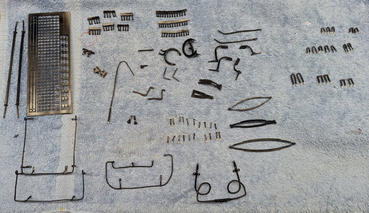
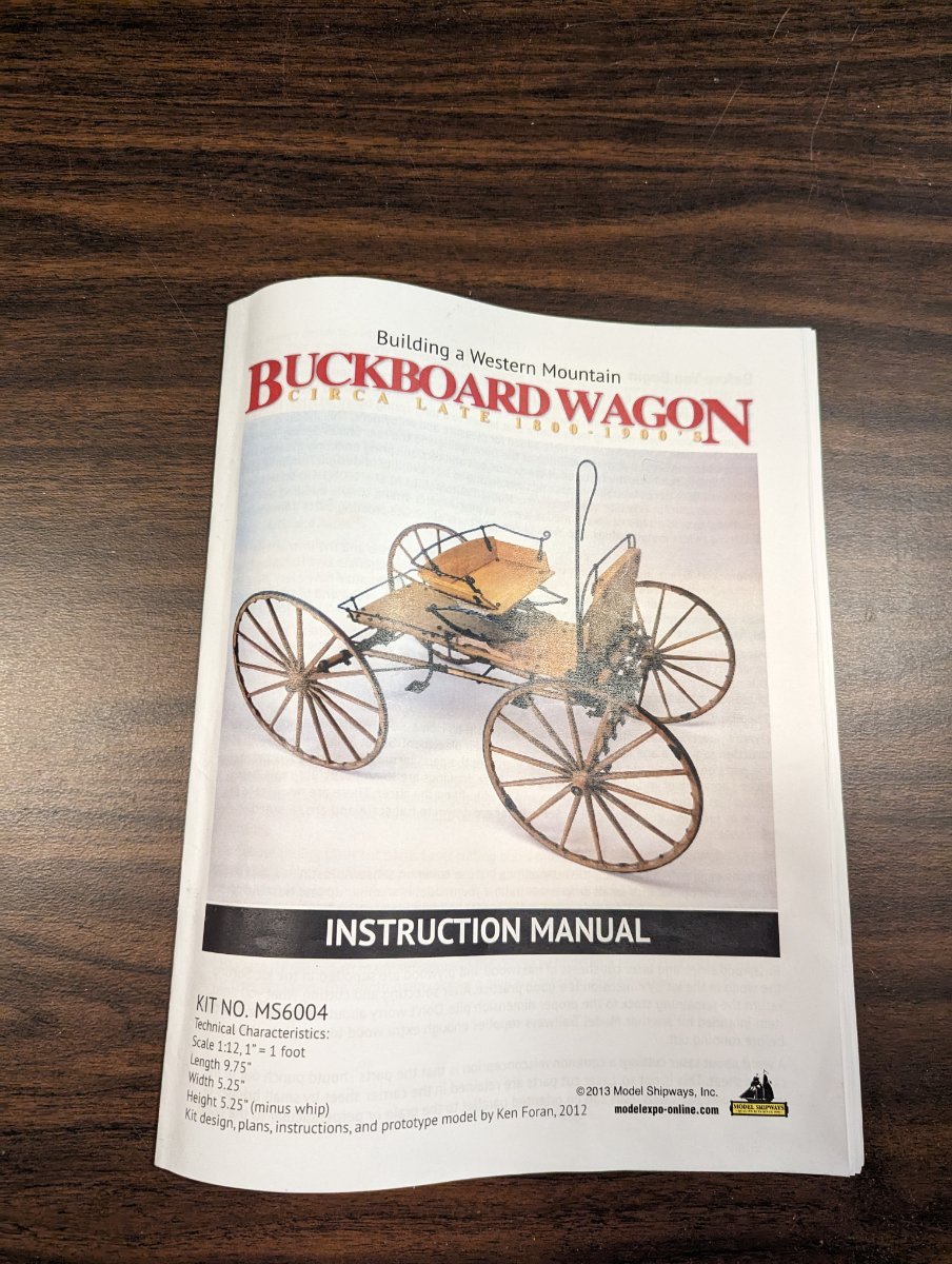
Hear is a quick view of the contents..
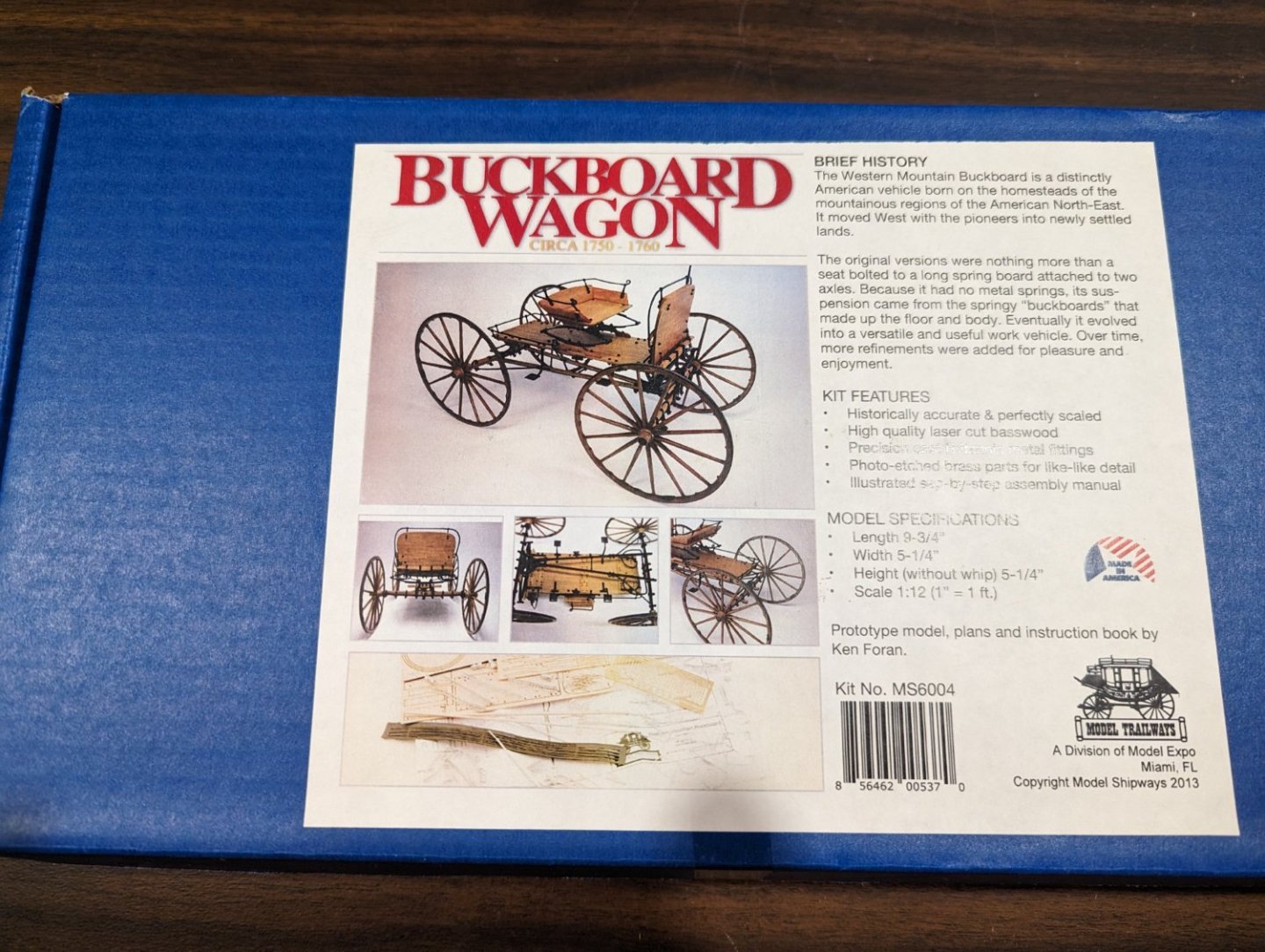
Seems like a nice instruction manual - about 50 pages with nice pictures.

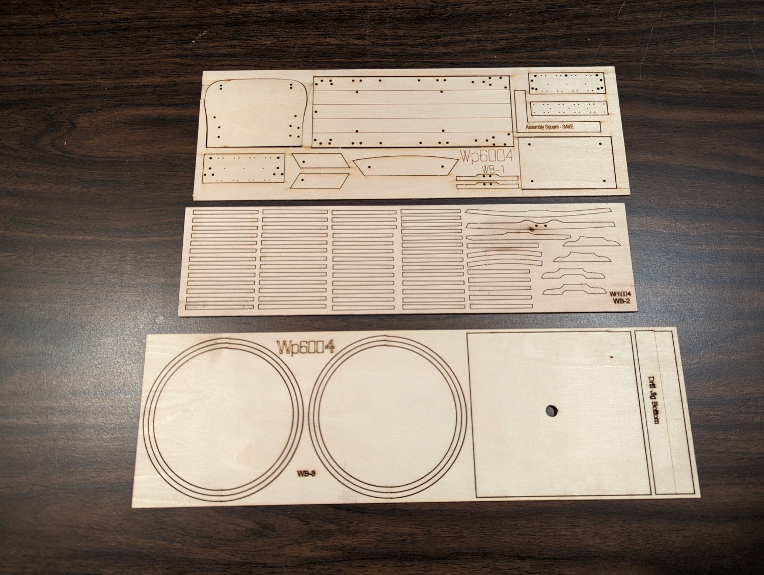
only three small wood sheets.. You can see why this falls into the "quick win" category.
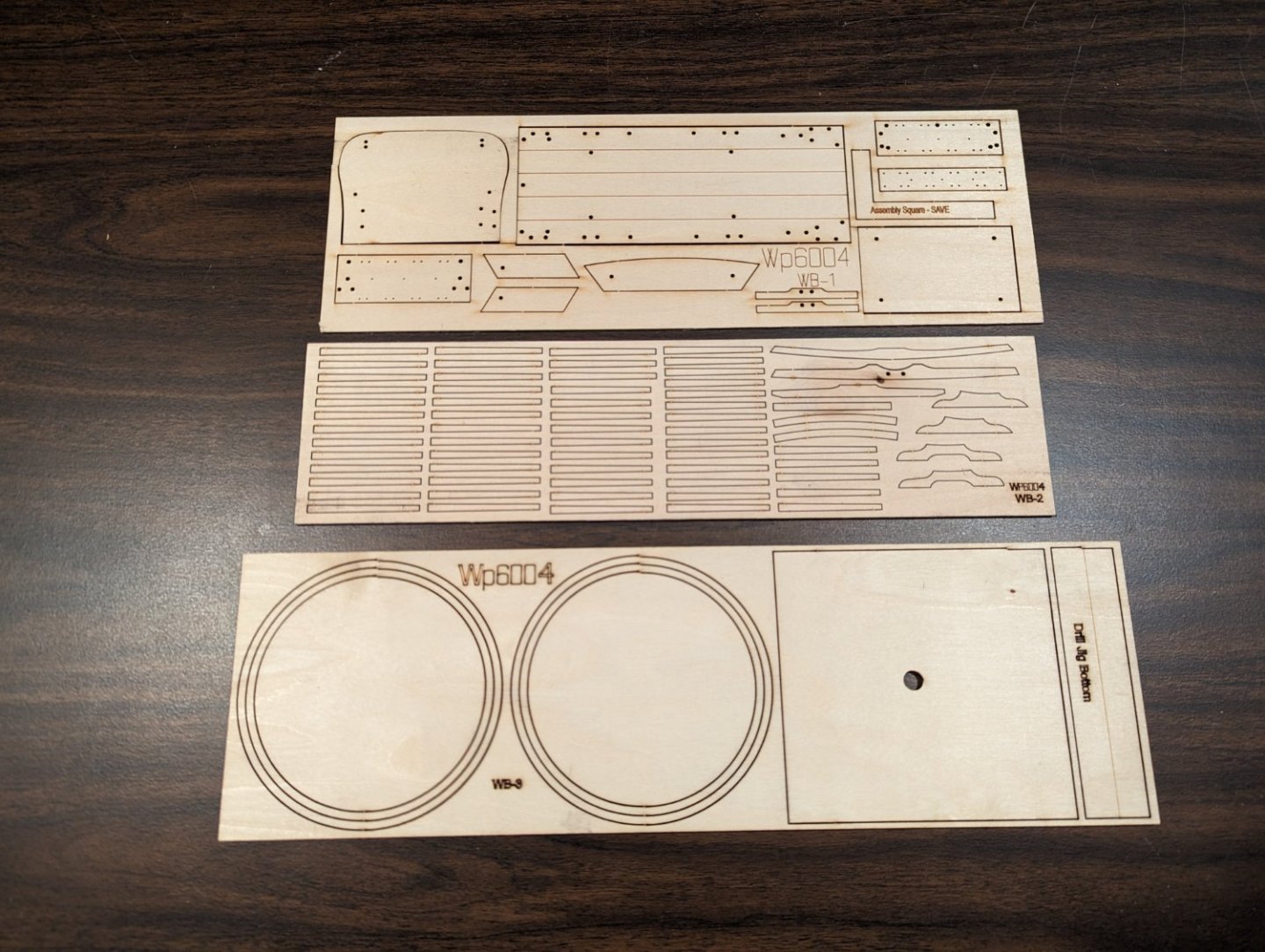
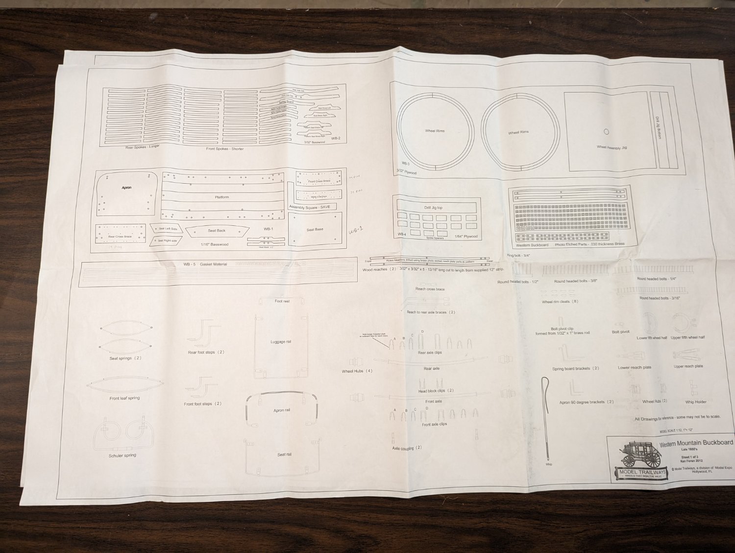
Three full page diagrams. The first one labeling many of the parts

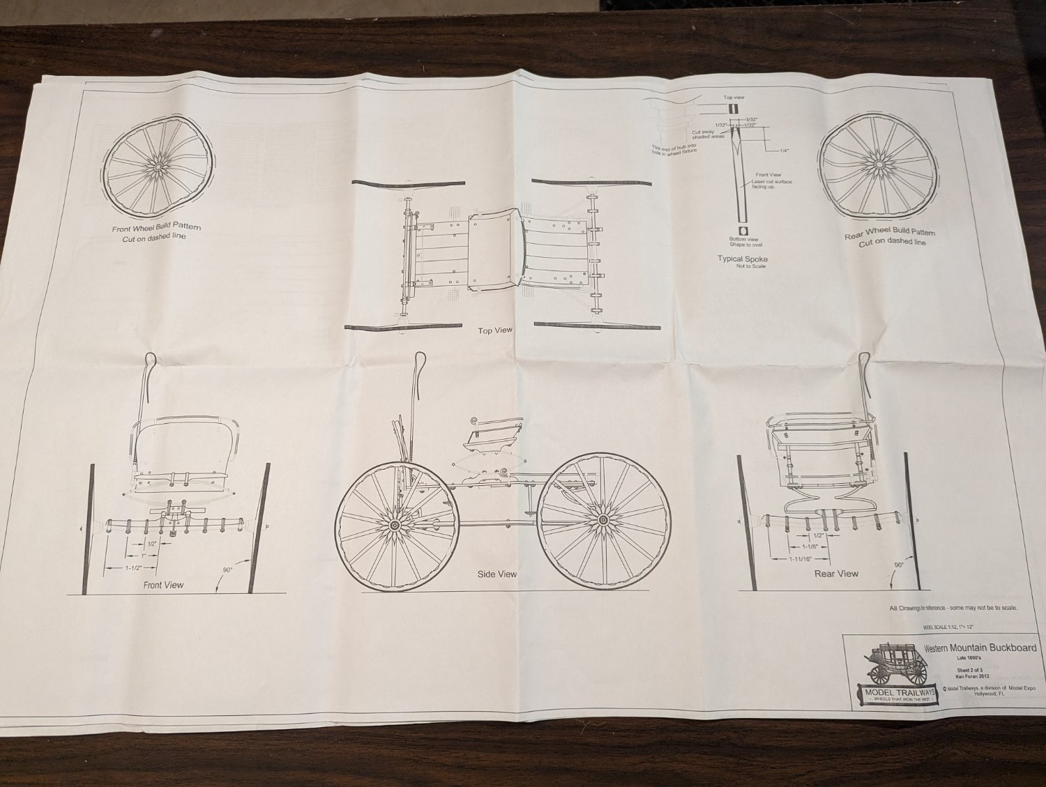
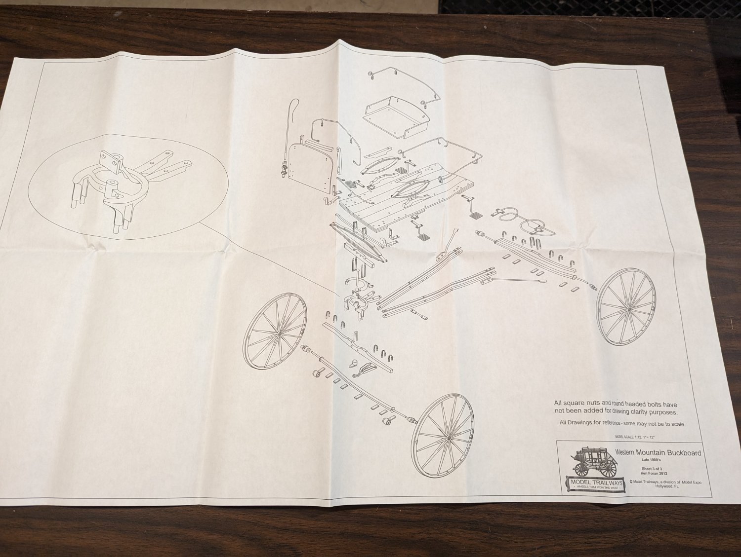
The 2nd and 3rd pages show various views and sections of the wagon
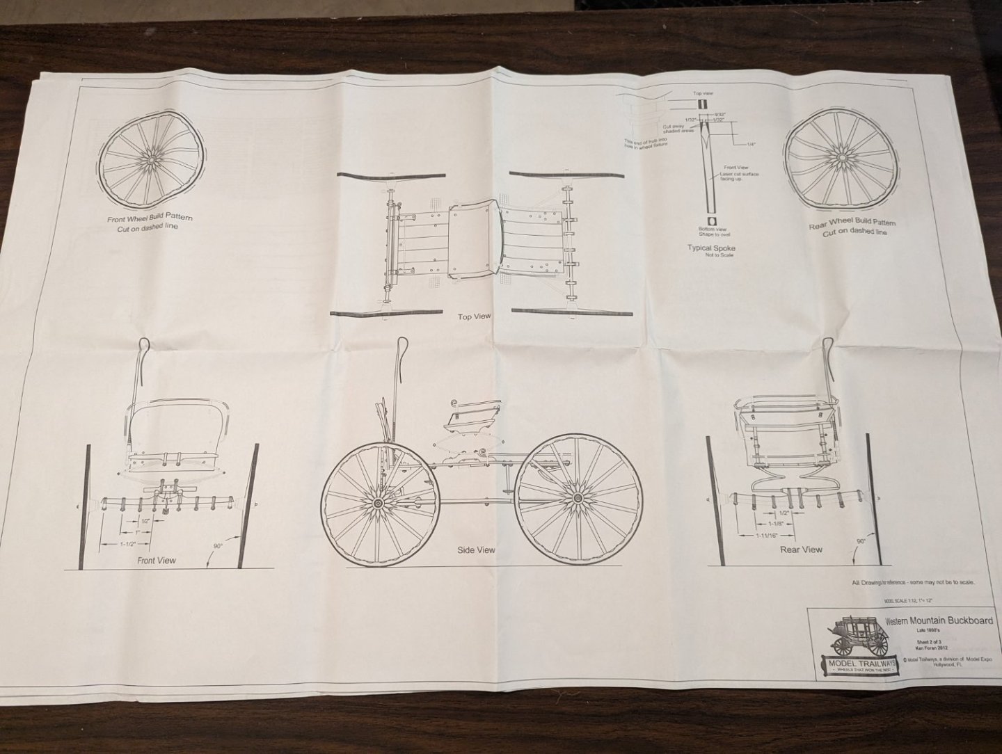

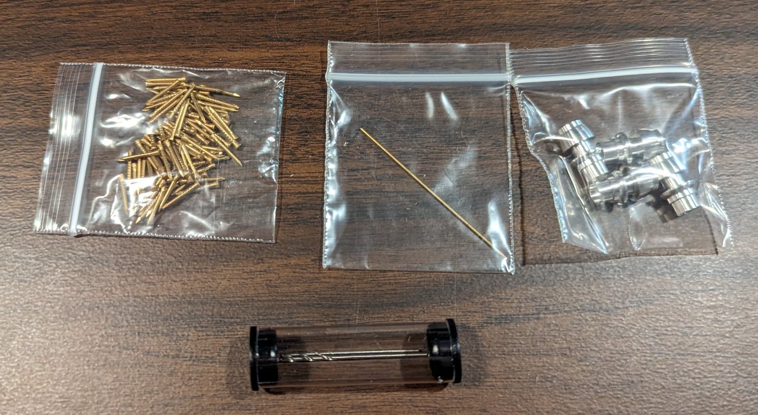
Pins, wire, wheel hubs, and 2 drill bits. The drill bits are a nice touch.

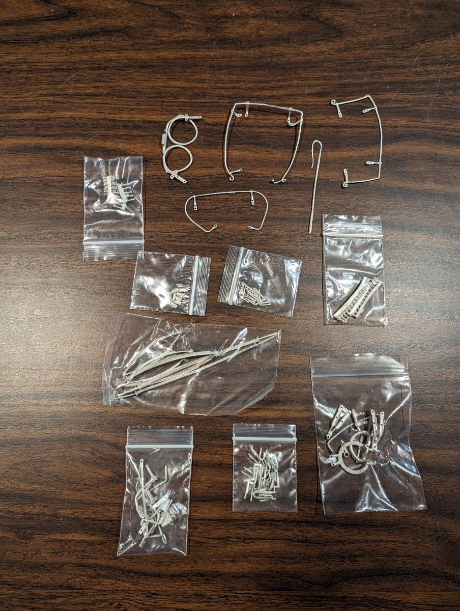
A ton of small soft BRITANNIA parts. UGH,,, some of these look so fragile, they look like they might break just looking at them... Will be (shall we say) "interesting" straightening them, cleaning them up, and painting them...

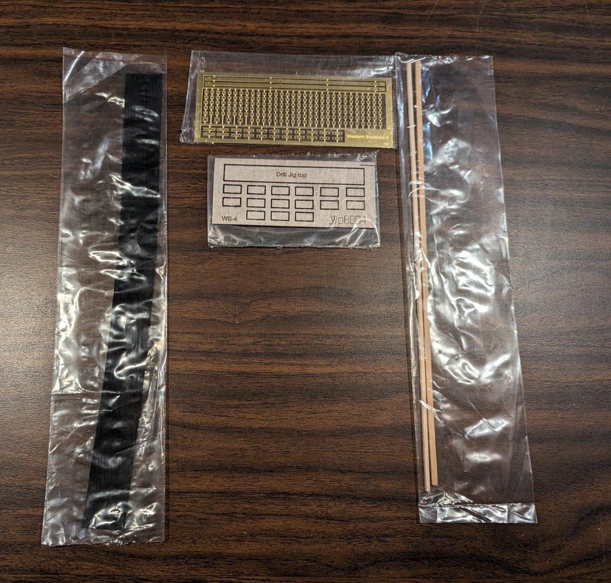
Finally some Photo etched parts, dowel, and wood strip, and a cloth sets of strips... (shown in black on the left).

-
-
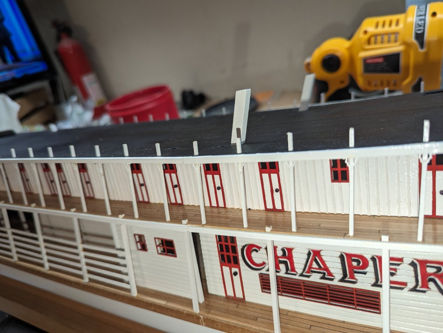
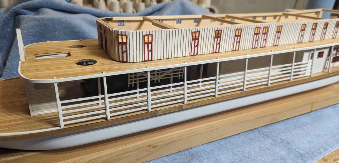
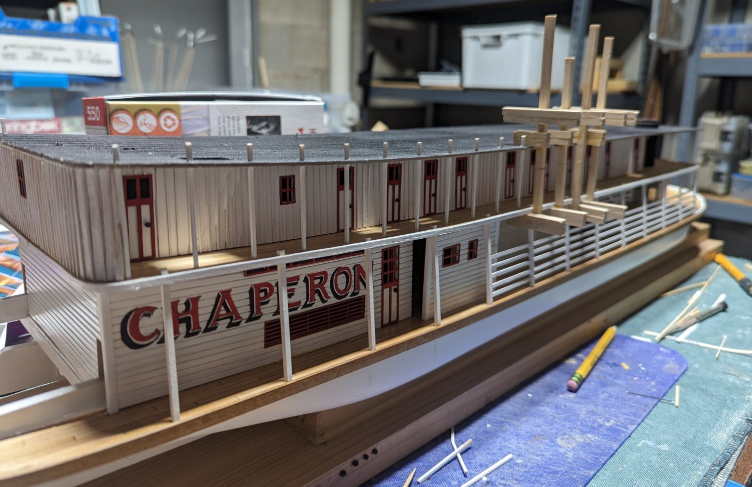
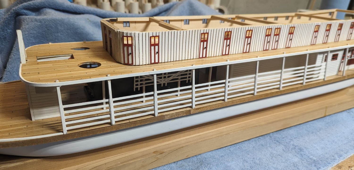
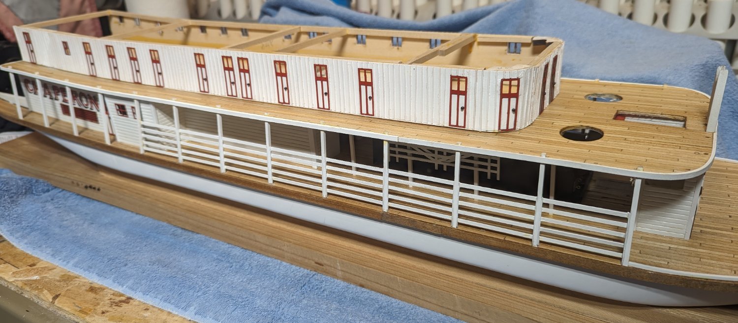
On to the outer bull rails.. These are 1/32" x 3/32" boards mounted on both the port and starboard side of the first nine stationaries. There are 80 of them - 40 on each side. The instructions call to mount the bull rails to parts 48 (bull rail brackets) mounted on on both sides of the stationaries on each side of the boat - "facing outward".. As mbp521 (Brian) mentioned earlier, this realistically is backwards. The bull rails are intended for the crew to be able to temporarily add or remove them to allow for easier loading or unloading cargo. Problem is with them facing outward there is no easy way for the crew (on board) to adjust them. Realistically the bull rails should be mounted facing inward. That way the crew can easily add or remove the rails as needed.
Having said that, while more realistic, mounting the bull rails from the inside is easier said then done. There are five rows of bull rails and by the time you get to the 5th row there is very little room for big fingers to easily put in the rails. It can be done, but expect to have some level of frustration putting in these 80 bull rails - and of course knocking some out as you go 🙂
Below is my attempt at the bull rails


Chaperon by John Gummersall - Model Shipways - Scale 1:48
in - Kit build logs for subjects built from 1851 - 1900
Posted
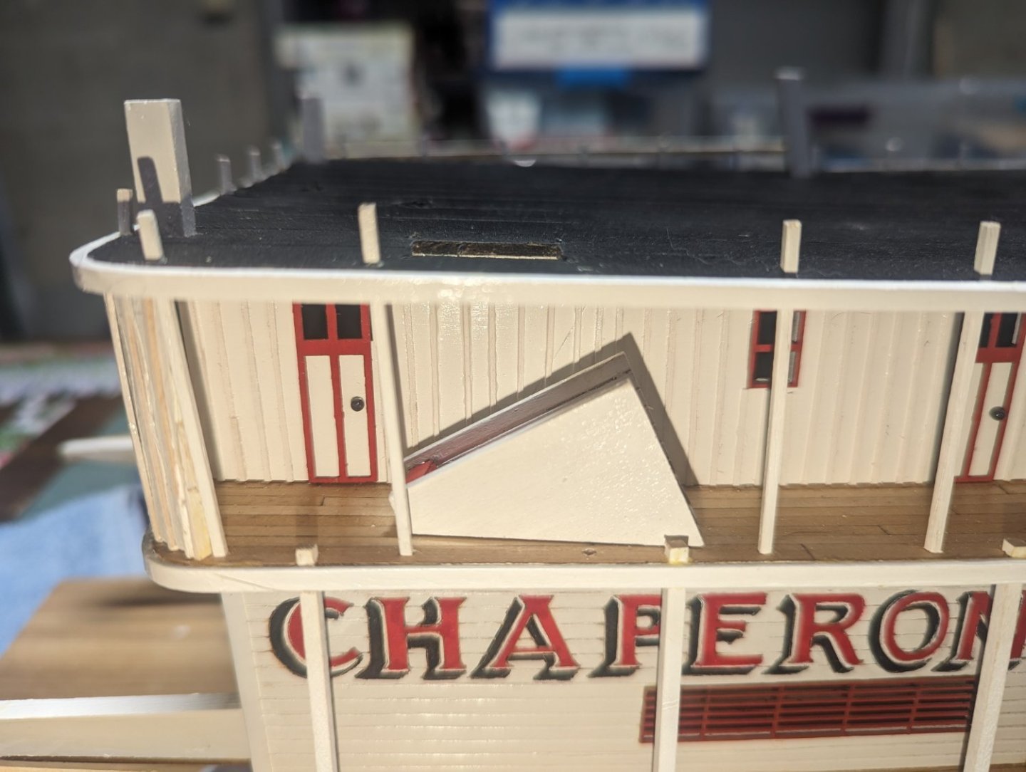
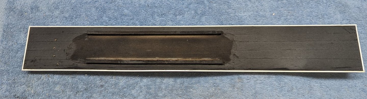
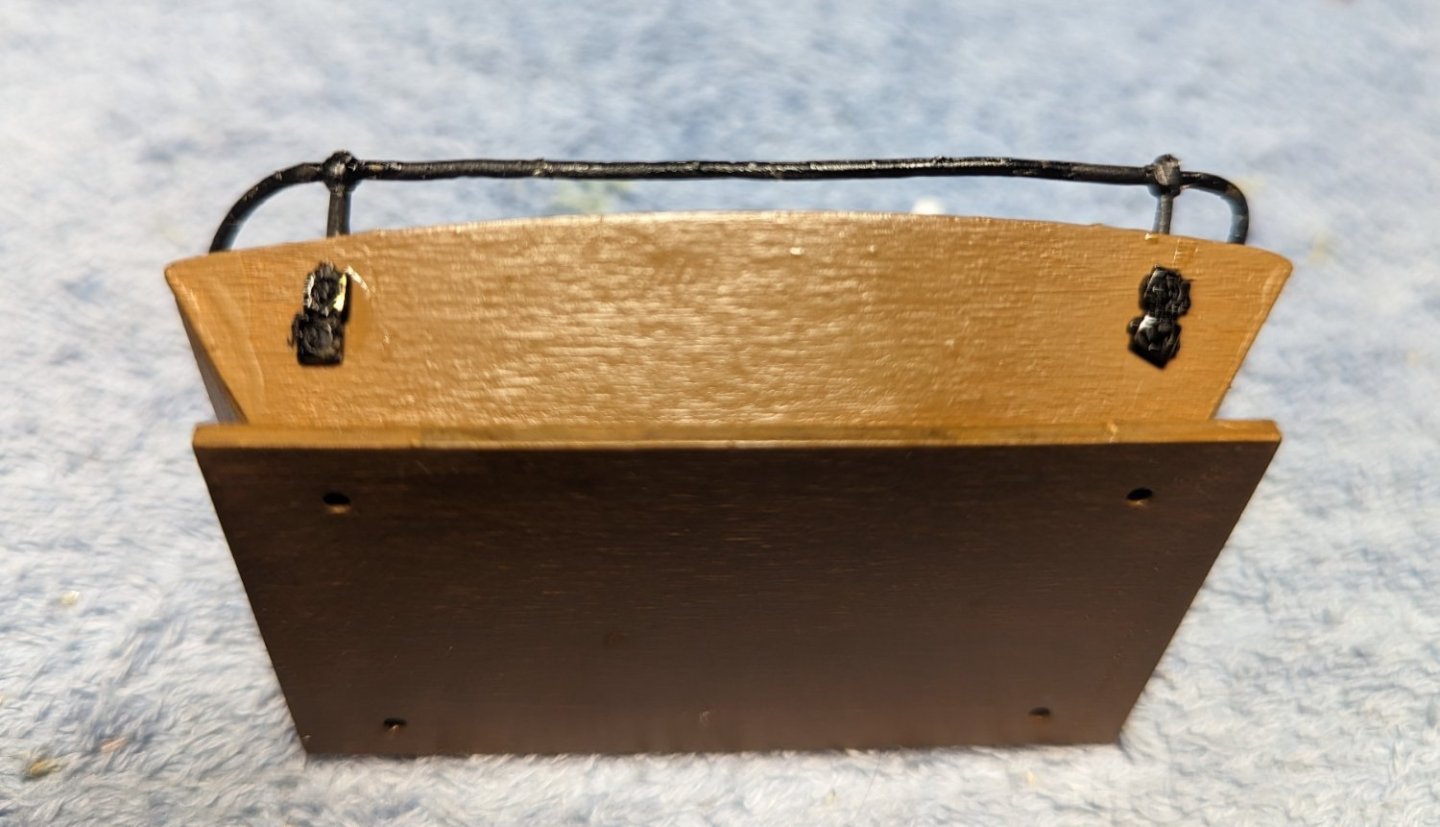
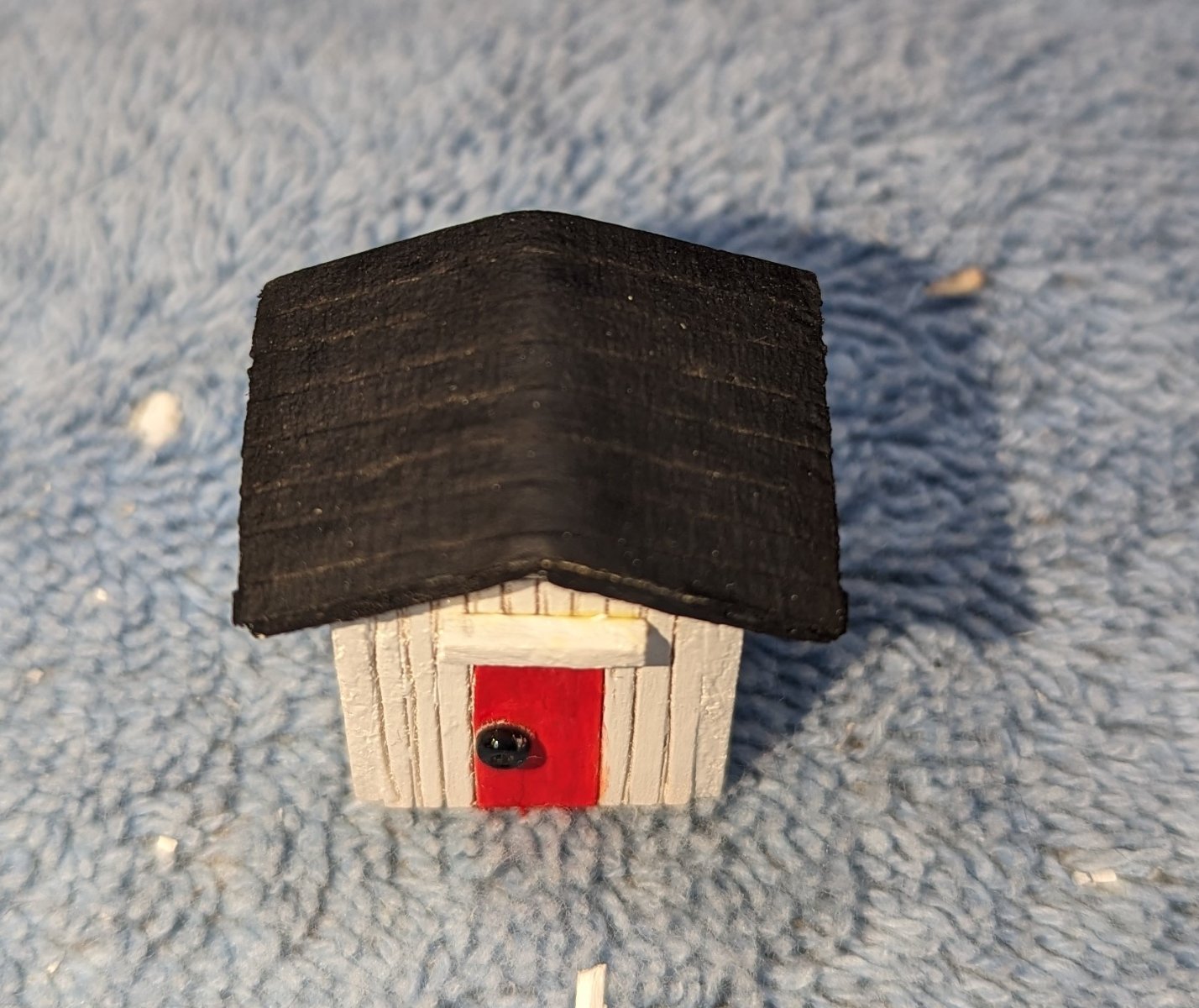
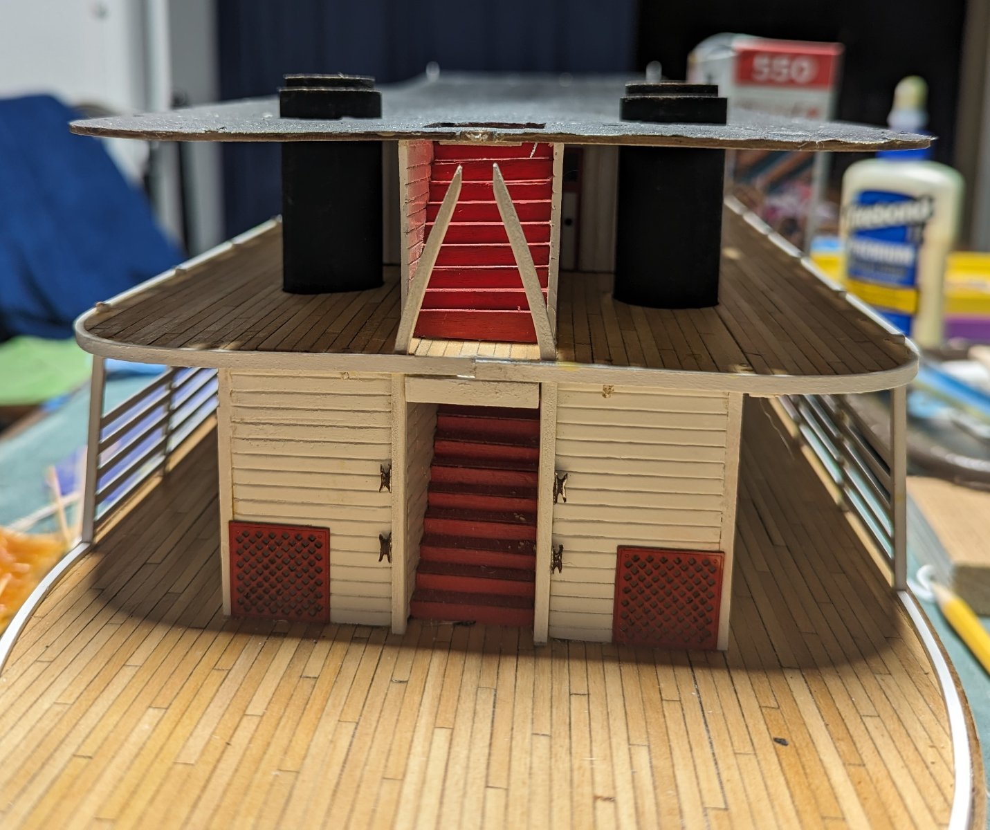
Got to working with the skylight... Back when I was struggling with deciding on the type of roofing for the various decks (that simulate tar paper) I ended up gluing masking tape to the decks and painting over it.
Here is a little "fun fact".... If you use masking tape, or tissue, silkspan to cover the roofs.... you need to cut away some of the material where the skylight attaches to the roofing Otherwise you are gluing the skylight to the material and not solid wood. After removing the weights holding down the sky light for gluing, guess what pops up? Ask me how I know this?
Anyway had to remove what little of the skylight was still attached to the roofing, removed the roofing around where the skylight was to be attached to the roofing, and glued it down again. While I am no expert model builder, that was a rookie mistake and I should have known better. I bet that mistake will not happen again 🙂
Below show the 2nd attachment of the sky light
Texas housing complete and glued on. The Texas roofing is in the background ready to be attached. I have a feeling I will not forget to remove some of the masking tape where the wheelhouse attaches to the Texas roof 🙂