BlackSeraph
-
Posts
41 -
Joined
-
Last visited
Content Type
Profiles
Forums
Gallery
Events
Everything posted by BlackSeraph
-
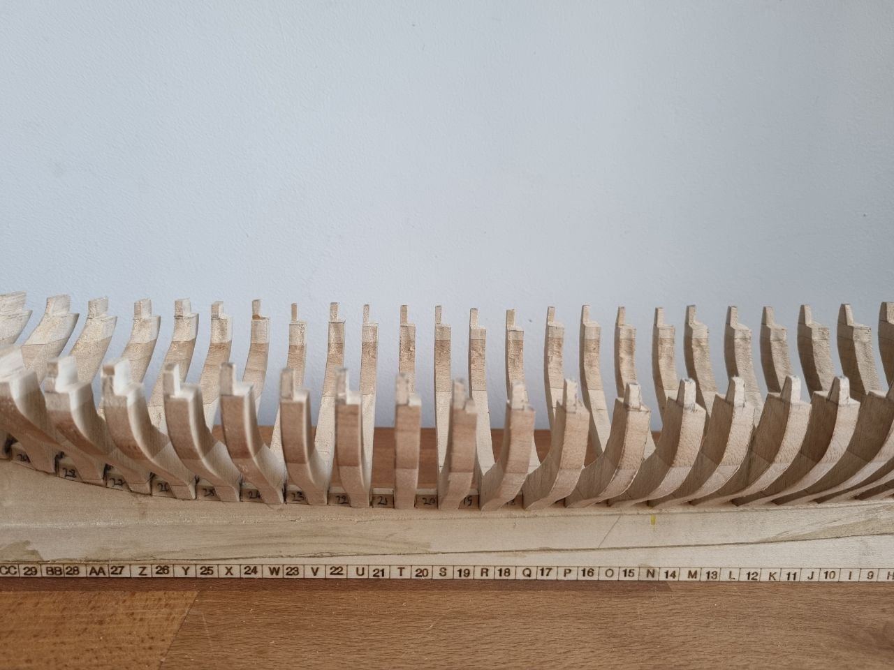
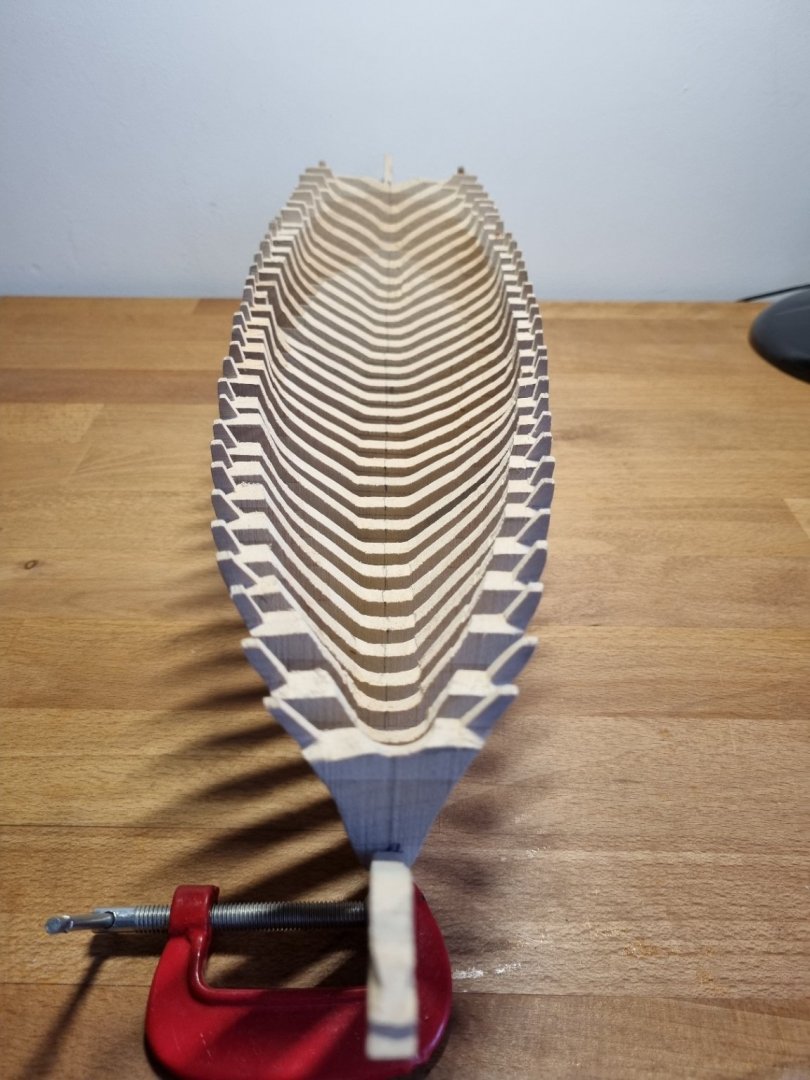
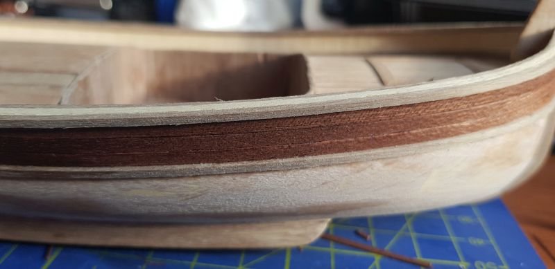
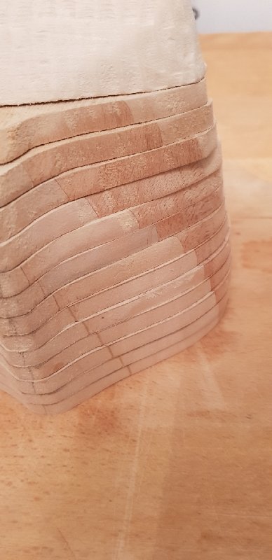
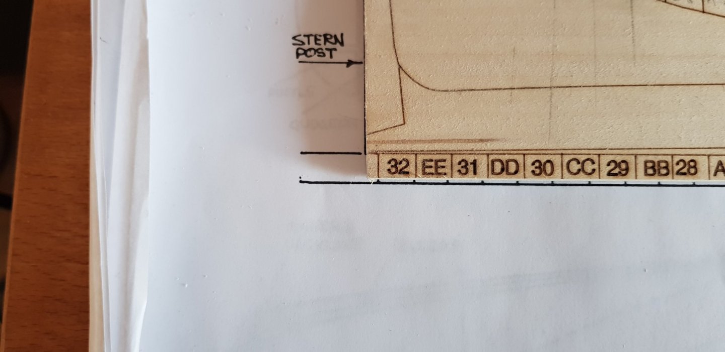
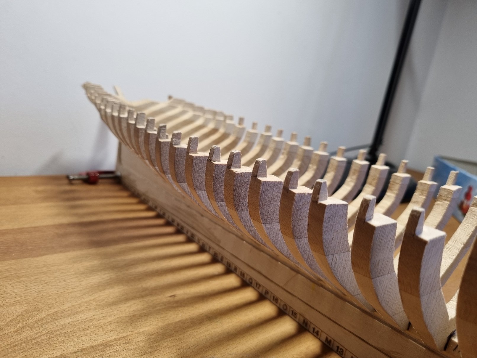
Unfortunately, I have to postpone this for an undetermined time. I was measuring and thinking about it for 2 weeks now and the only way to make it work is to re-do lots of frames. One third of fore frames are shorter, A- frame is 4 mm shorter. Aft ones are not wide enough, some of them; I spotted one which I cut, but also there is one I didn't. The transom is too wide, but I measured it against the plan and is correct. If I take into account frames which are not wide enough and the inside carving, which is far from what is shown in the book (it can be seen that is closing on EE frame - last one - but in book it goes within transom piece) I would say that the machining was not OK relative to plans, which I didn't checked , though I couldn't do anything about it (wide). Also, it can be seen how lines flow to aft and how they don't match the stern piece curvature So, I will summarize here what I learned: it would be useful to have frame's drawings to check against the machined pieces check each frame height. If height is not enough (the bottom must align correctly on bearding line) is better to add some material on top before cutting keel slots measure the corresponding frame thickness read and understand the instructions very well. There are lots of things you need to link together start from middle and work aft and fore. Fix the frames with some light glue (I had some rubber cement, but it was a bit soft) and follow the recommendations: measure and test that everything fits naturally before gluing, including insides - take into account how they must flow Do not cut stern and stem pieces until you finish the frames. Do not rely on plan measurements only. The lines must flow naturally; in my case, even if the aft frames are not wide enough, they still can be fixed, but the stern piece has to be smaller
-
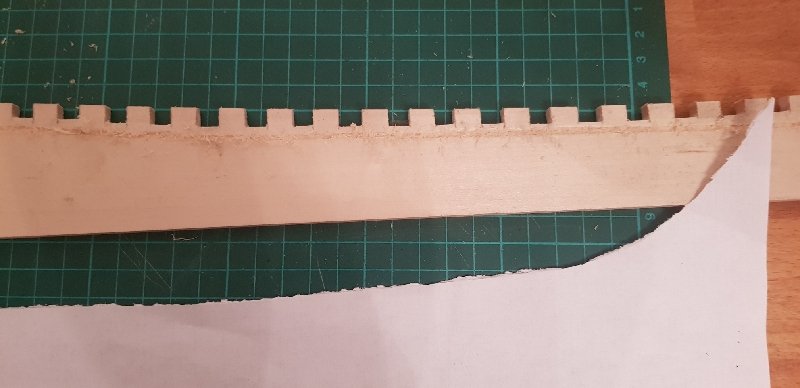
Hi Gary Thanks for the advice, I was considering the same thing because the wood is soft, right. The frames ARE way off, believe me, I tried to capture in the first picture. And the step is there, in theory, but frames are off. It took me too much to measure each one and, when I affixed it, it was still off (on height), so I said that is simpler if I fix them at the end. Just look how far they are, and you can trust me that I carefully measured the timberheads. In fact, I have high hopes that I will solve it easily with a hand tool from Proxxon with a fine cutter, due to soft nature of the wood. By no means I'm saying I didn't made mistakes, I just said that measuring is not enough. To be honest, I would choose another approach now, but this is where I am. I think one should measure the frame height with the slot in the keel against the plan. The slots might be cut correctly, but the frame most likely is not perfect like the ones laser-cut, so it needs to be adjusted. This is my first built after plywood models, so I assumed that the sizes are [mostly] right.
-
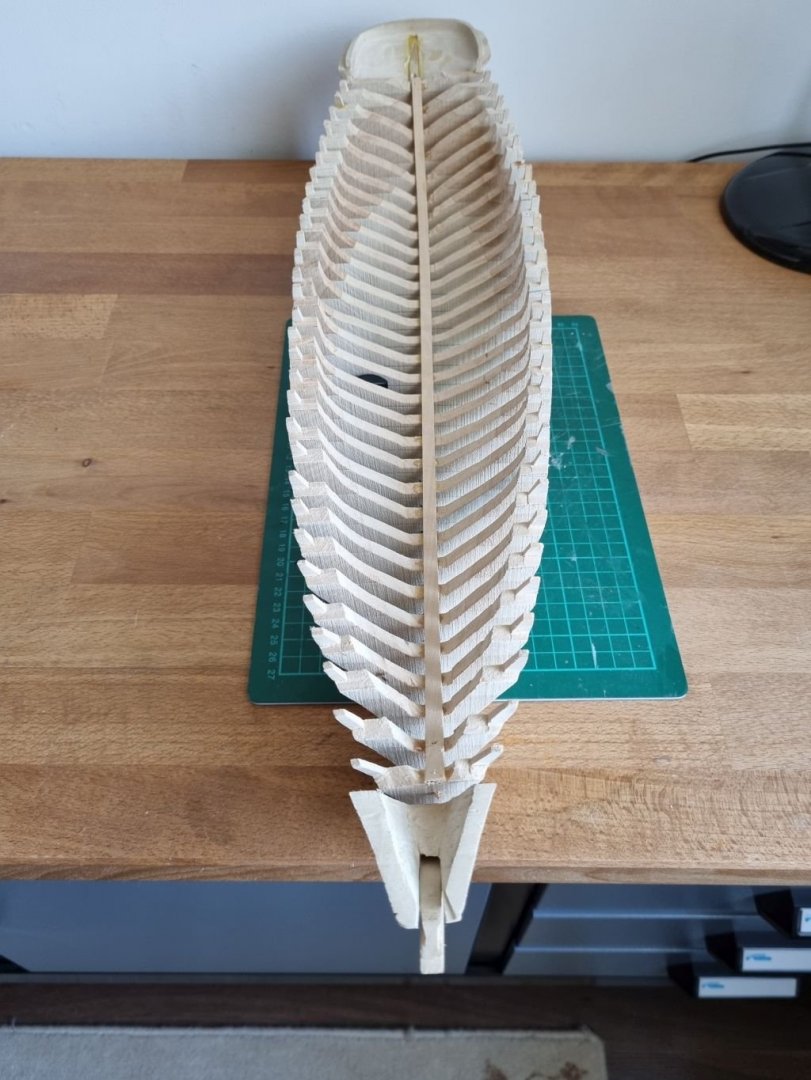
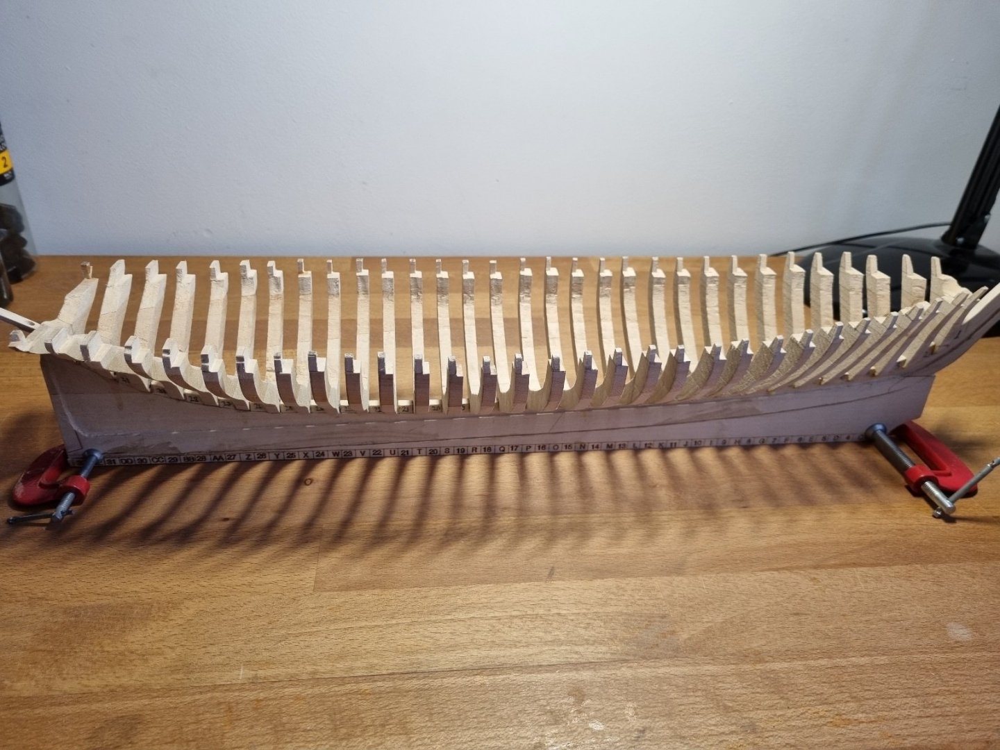
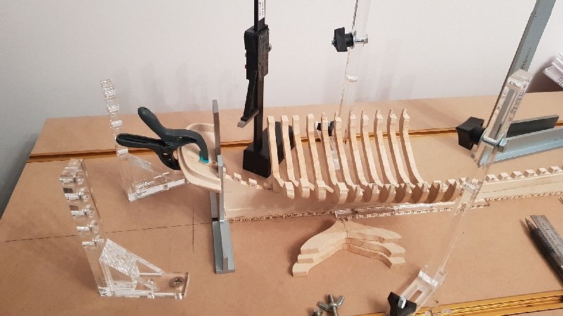
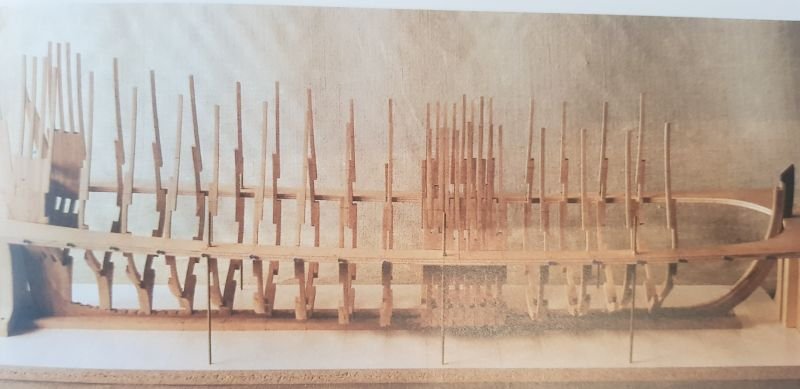
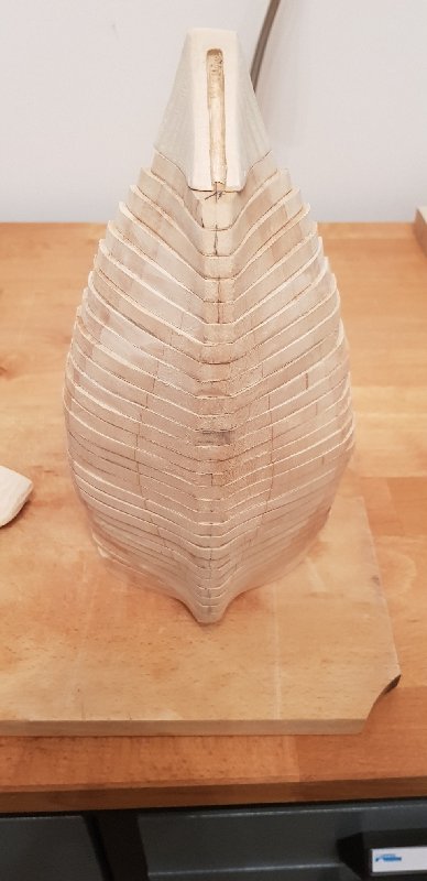
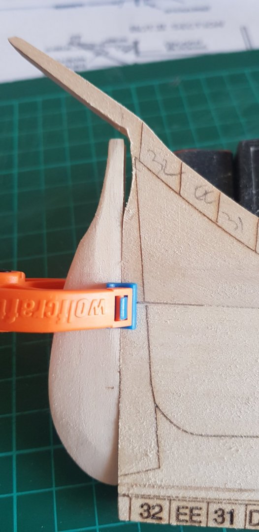
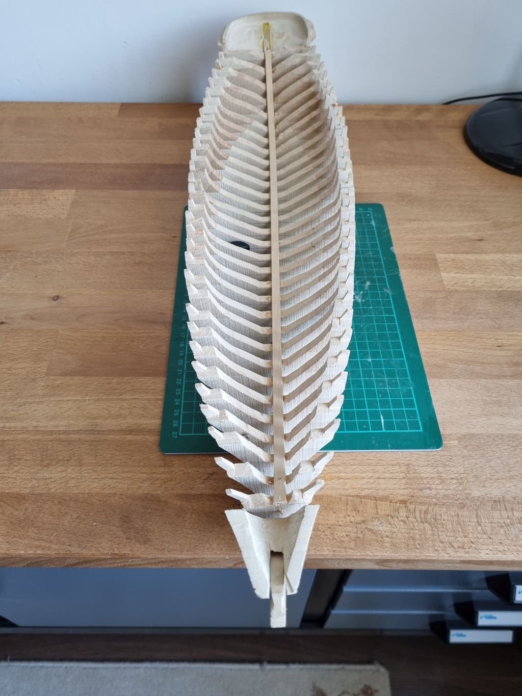
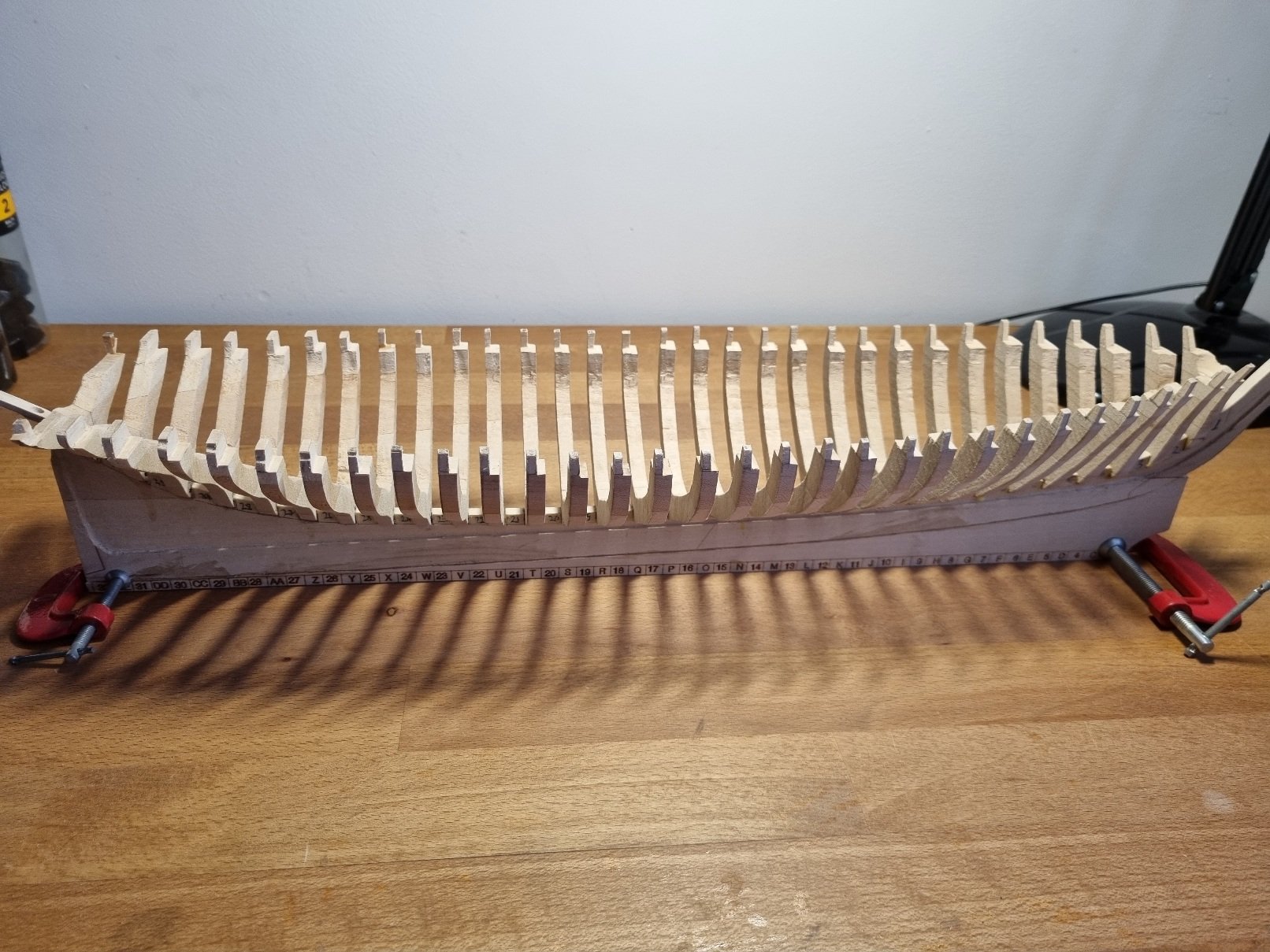
Hi Well, long time no see. My workbench was requisitioned by my better half. We both work from home for most than one year. But I got it back! Meanwhile I worked on small projects which I could do on a regular desk, next to my keyboard. https://www.facebook.com/media/set/?set=a.3346772168708512&type=3 https://www.facebook.com/media/set/?set=a.3649595848426141&type=3 https://www.facebook.com/media/set/?set=a.3827967460588978&type=3 https://www.facebook.com/media/set/?set=a.3856386867747037&type=3 So I've been busy today. Finished all frames on fast-forward mode, I realized that I can do same thing without assembly table because the errors already present, which will require a lot of work. Effectively some frames are completely out of line. I'm still thinking how I could've determined the right dimensions - see the side picture I think I'll try to fair the hull, then install the stem and stern pieces

-
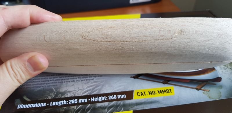
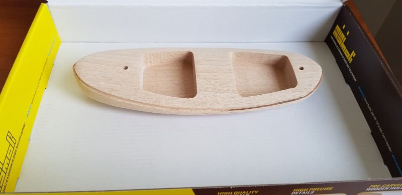
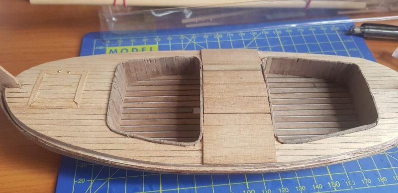
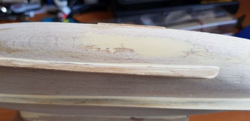
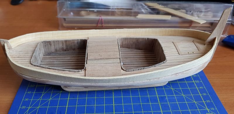
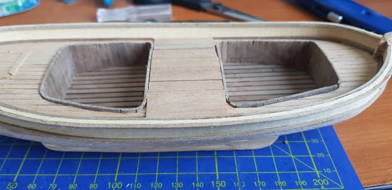
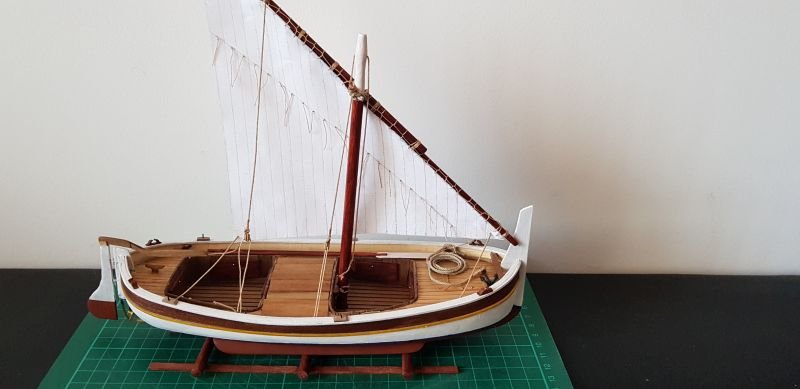
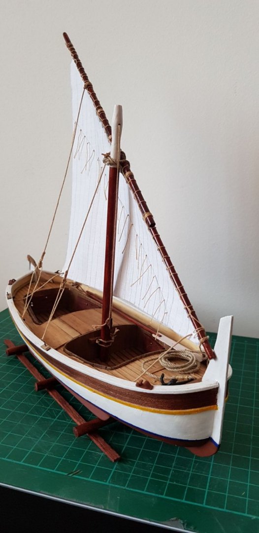
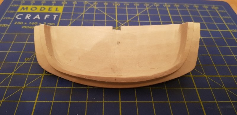
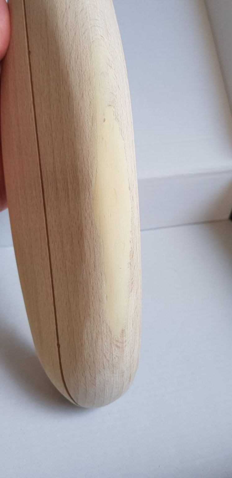
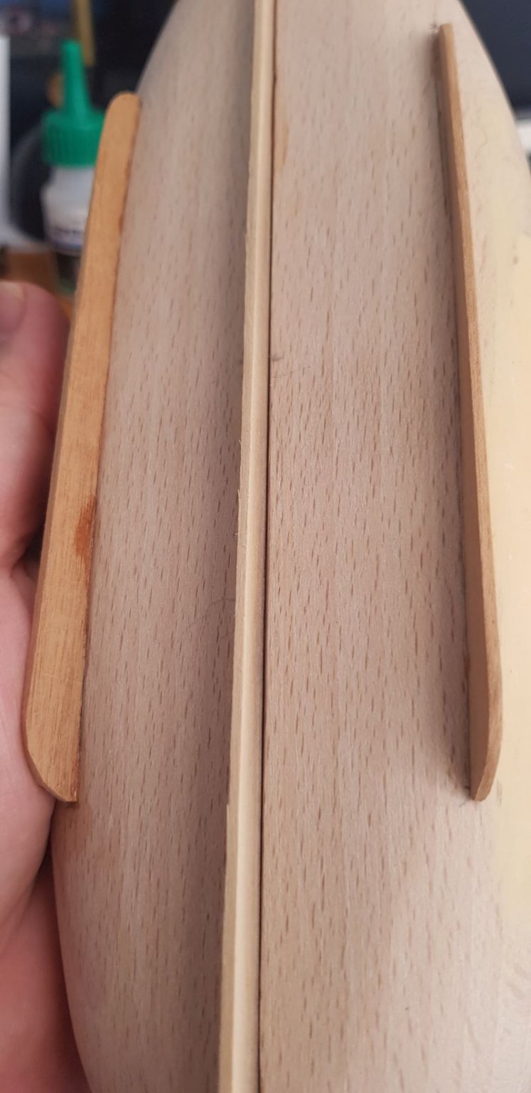
Due to COVID pandemic me and my wife have to work from home, so my workbench became an office desk for her and I could not work anymore on other project, America. I have to adapt and I got smaller builds. Here's Gozzo vela, from Mini Mamoli (now part of Dusek Ship Kits). The kit is quite simple and fun, but there are several problems with it: Some wood sizes mentioned in instructions are missing or are not enough The pre-carved wood hull has some flaws (see below) The instructions seems translated with some automated tool (I read English, not sure about original Italian) The instructions doesn't seem very detailed, basically there are no details, just enumerates some steps, quickly Most wood used is walnut, but is very thin and is breaks so easily I made some mistakes: I tried to fix hull creak with filler, but it was broken and it raised over surface which was mean to be smooth, so then I decided to throw away that part and fill it. Then glued the board on the hull instead of top of it (I let the walnut strip 48h in water and I used a plank bender, but it still broke). I unglued it and used some strips I had at home and I think it looks better. The strips used for keel need thinned. Is VERY hard to make them follow the groove, so did the best I could and then just glue and trim-fit it. I painted using brush (no airbrush yet) and some shellac at the end


-
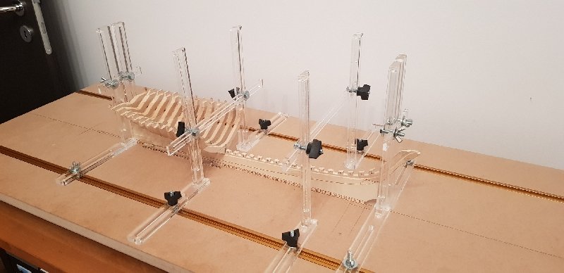
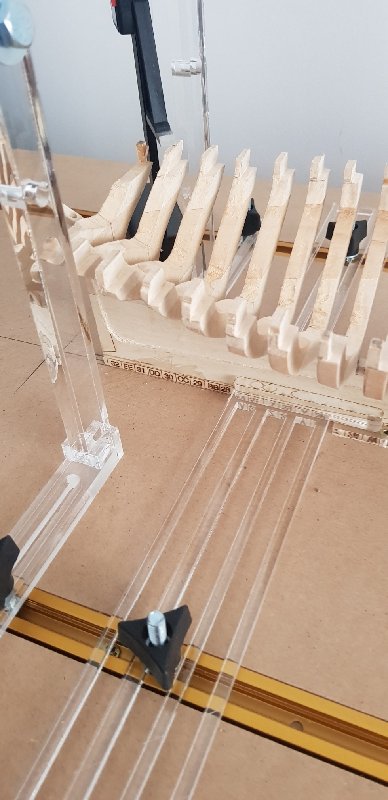
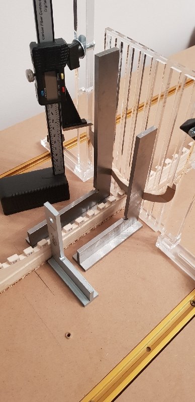
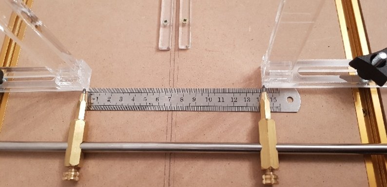
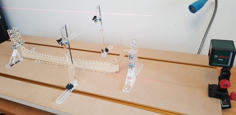
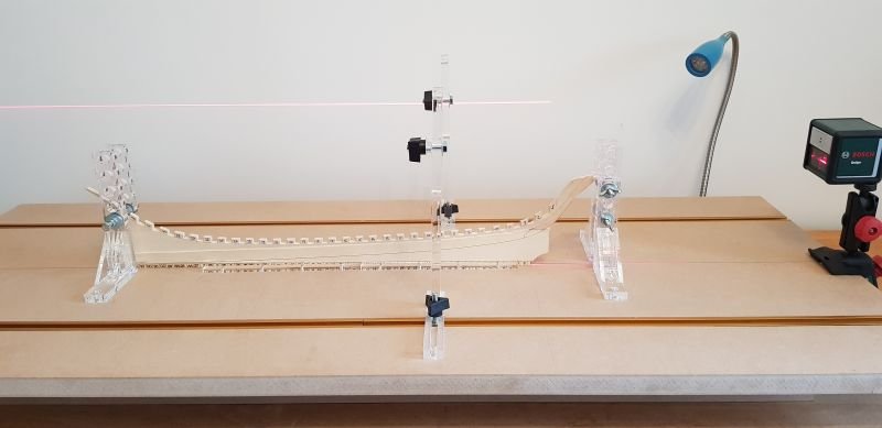
Finally I finished version 2 of the scaffolding. Actually version 3, because v2 were made from 5mm steel but the stupid guys didn't took into account metal dilatation and were cut curved. The 10mm ones I use to hold the keel are not straight, they are curved too, but it doesn't affect their functions. The others are graded. The frame is perfectly aligned horizontally and vertically and hold between inside lateral ones. Everything can be adjusted both horizontally and vertically!
-
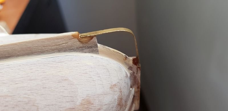
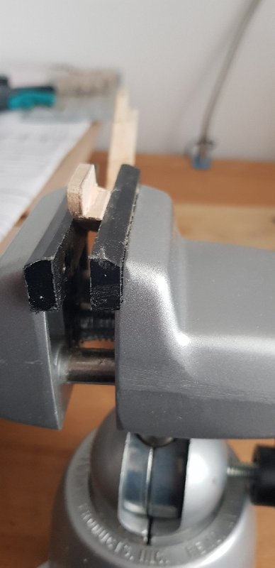
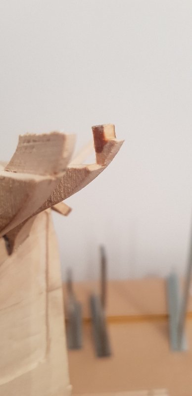
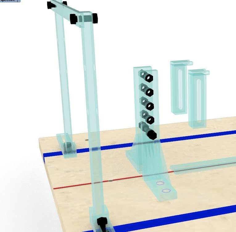
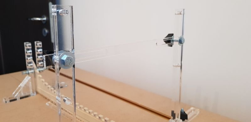
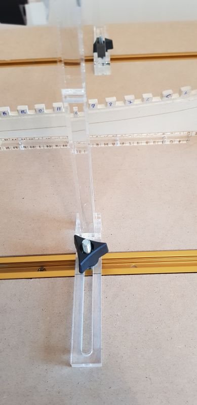
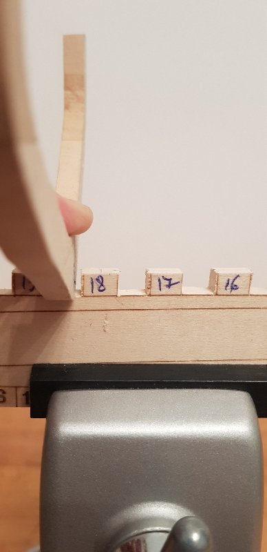
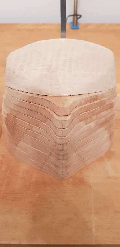
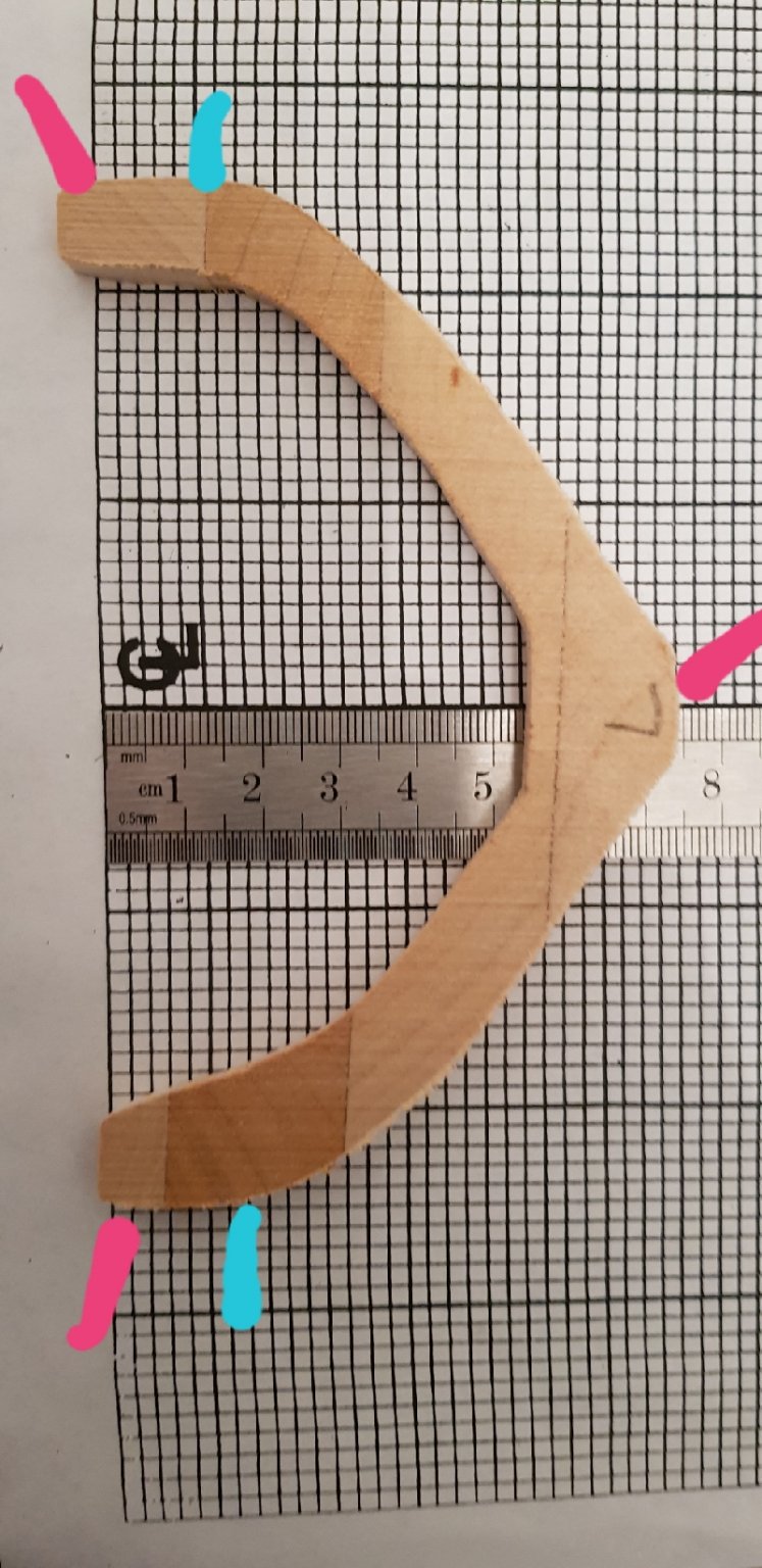
The keyword for this post is "mistakes". Please don't forget this is a build log a not building instructions. The most important thing one should do is to cut keel slots of proper size, so the frames will stay in place by themselves. This will save you lot of pain and few years of your life. The last 5-6 frames have recessed timberheads. The frames must be fixed so the measurements can be made and see how it looks. As is indicated in building book. I tried to fix frames with rubber glue, but is too flexible. Then I challenged gods and I worked by measuring everything. It doesn't work well, there are differences between frames around 1mm, is the best I could produce. I built the stern using the milled piece of wood. Measured on plans, dimensions and curves. Tested and affixed on horn. BIG MISTAKE. After I fixed the last frame I realized that the hull curve doesn't match. The sides are correct, but under hull curve is more steep. So I cut the horn, unglued it from stern, cut a slot for it and then tested again. Better, but still not good. It can be seen in a previous picture that there is steep differences between last frame and stern. I think that @gsdpic is right and lots of material must be removed. I will fix all frames, then fair (?) them and see how I can solve stern issues. Another HUGE problem is the wood, which is soft. As I said, the last frames have recessed timberhead. The shape is a bit complex and the wood breaks easily. Like 5 times a timberhead. So, what I did was to half cut the timberhead and fix the frame. And use a vise to keep the frame tight; I didn't break anything after that. Then, when all are in place, I will mark it and cut it in place. All this pain could've been avoided if keel slots were cut right! On a different topic, I struggled to measure and keep in place at right angle the frames. And keep the keel from moving. For this I reused a piece from plexiglass board and that gave me some ideas about a system. I designed it, I need someone to cut the pieces for me. I'm very excited to see it done. Keep close, is pretty crazy.
-
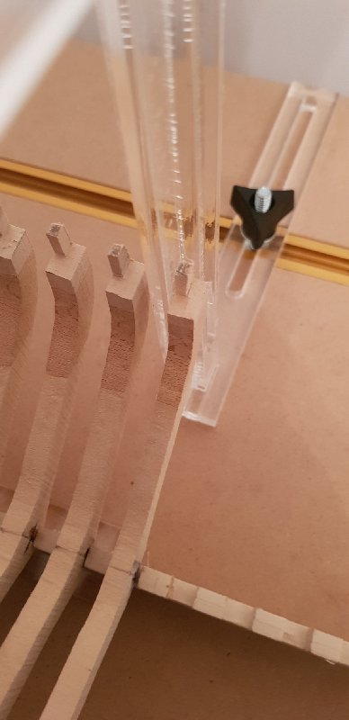
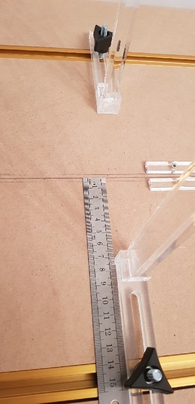
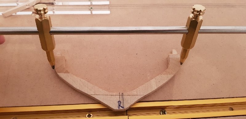
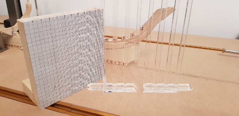
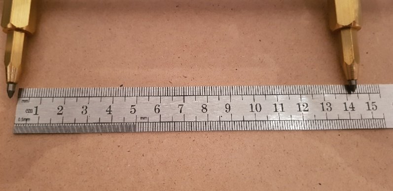
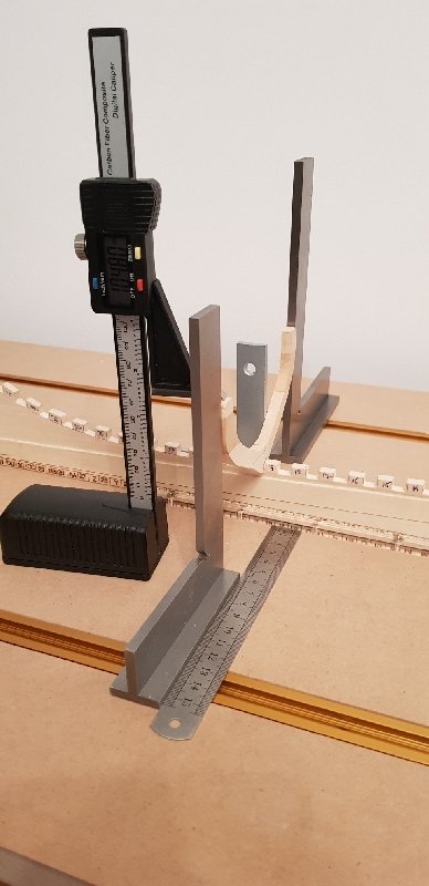
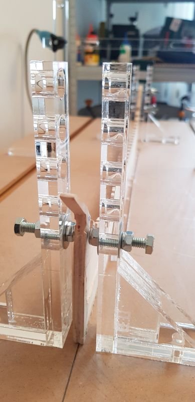
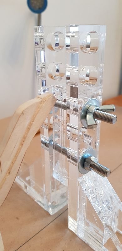
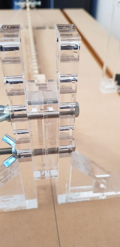
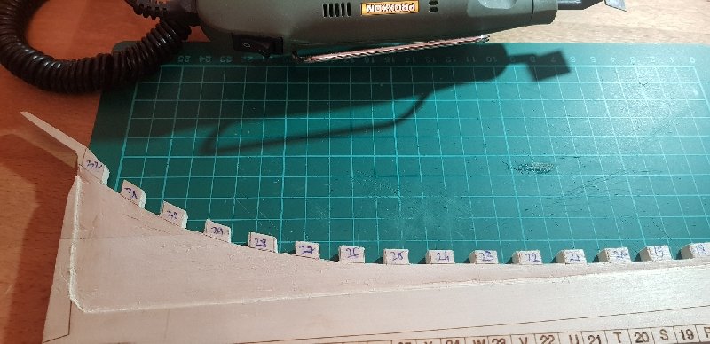
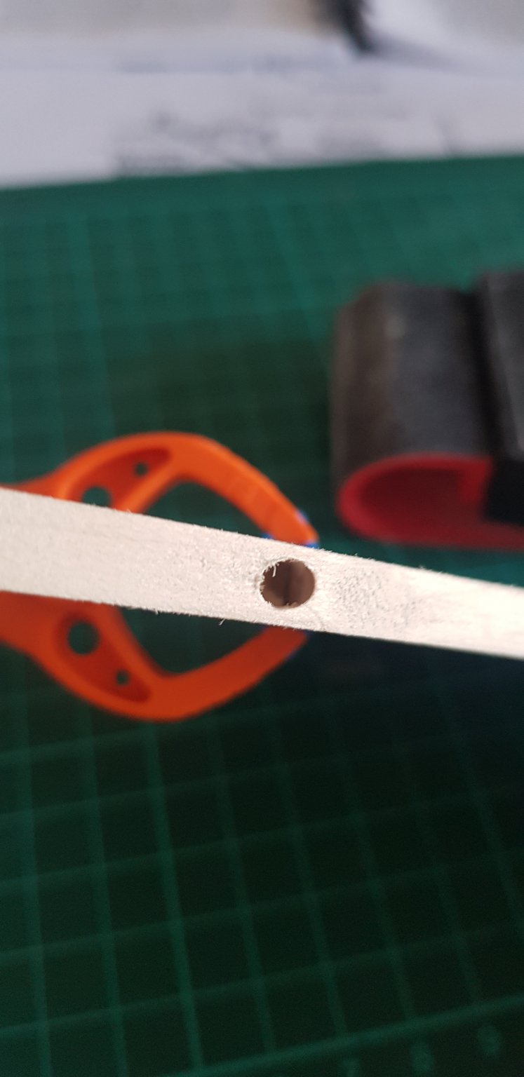
I apologize for disappearing for so long, but my back pain prevents me from working. I have a desk job I tried several ways to install frames. Normally they are fixed temporarily and mark cutting line. As I said, because the slots are too big, it takes too much time to fix them. In the end I decided to install and cut one by one, checking against previous one. I was inspired by other builders and I used some gadgets: A small piece of wood to help me measure 1/8 timberheads: A tool made by a friend meant to draw circles, but very useful in porting dimensions: I fixed the frame on keel slot, taking care of measurements and angles (keel and frame vertical, height the same on both sides), took it off, then, using the small piece of wood, I marked timberhead, cut it, then fixed it back on keel. Great care was observed so the squares will not be moved. You can notice the utility of plexiglass squares I built as part of assembly table - they are fixed in place with screws and help keep the sides A square plank might be useful to hold frame in place at right angle (instead of two metallic squares). Best is to have a board cut in the middle to accommodate the keel. The plexiglass one is more a POC because is too flexible, but one can be made from wood. Or the wood one with measuring paper, as the book recommend, but I find more useful one which goes both sides Please note that measurements were made relative to center line on the board and the keel either has to be fixed or, in my case, I marked keel width on both sides and took those into account when placing small square for keel verticality

-
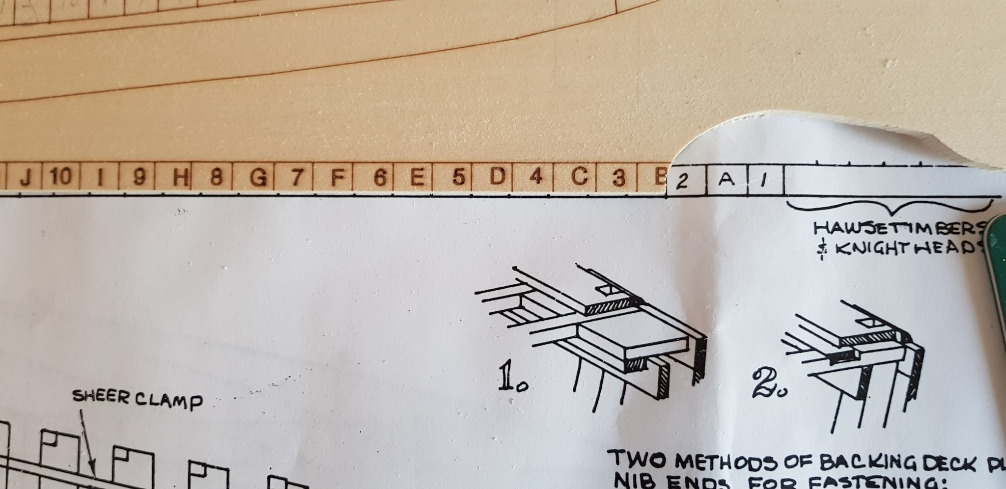
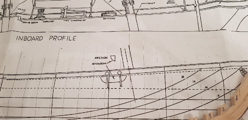
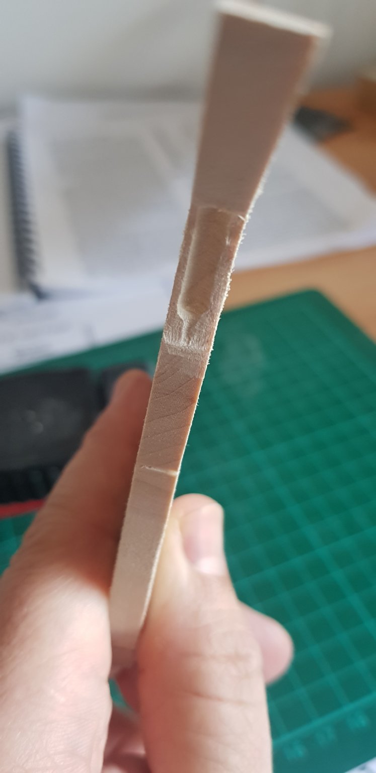
Some health problems prevented me from working. In the meantime I learned how to use the lathe Normally now I should test fit the frames. Unfortunately it takes some time to fit them and they are not tight fit, so they have to be fixed somehow. One solution might be Elmer's rubber glue, other to use some pieces of wood. I tested one, marked position and removed then tried to put it back. It requires again some time, so I decided to skip this step and assume some discrepancies when I will affix them in one step. Now I decided to cut the part below the keel and fix it with rubber glue. Is going to be hard to do it after the frames are in place. The next step is to cut the frames for timberheads. The process is well explained in the book, but it wasn't so obvious for me when I read it first time. The distance is calculated using sheer plan, inboard profile and station sections, but you need to consider the thickness of the deck and of deck beam end, while in plan you only have the distance from underside of railcap to the deck. I found useful to draw frame positions on the plan, otherwise takes some time to determine it for each one. The process of cutting frames is throughly described in the book.
-
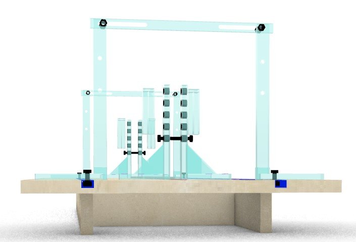
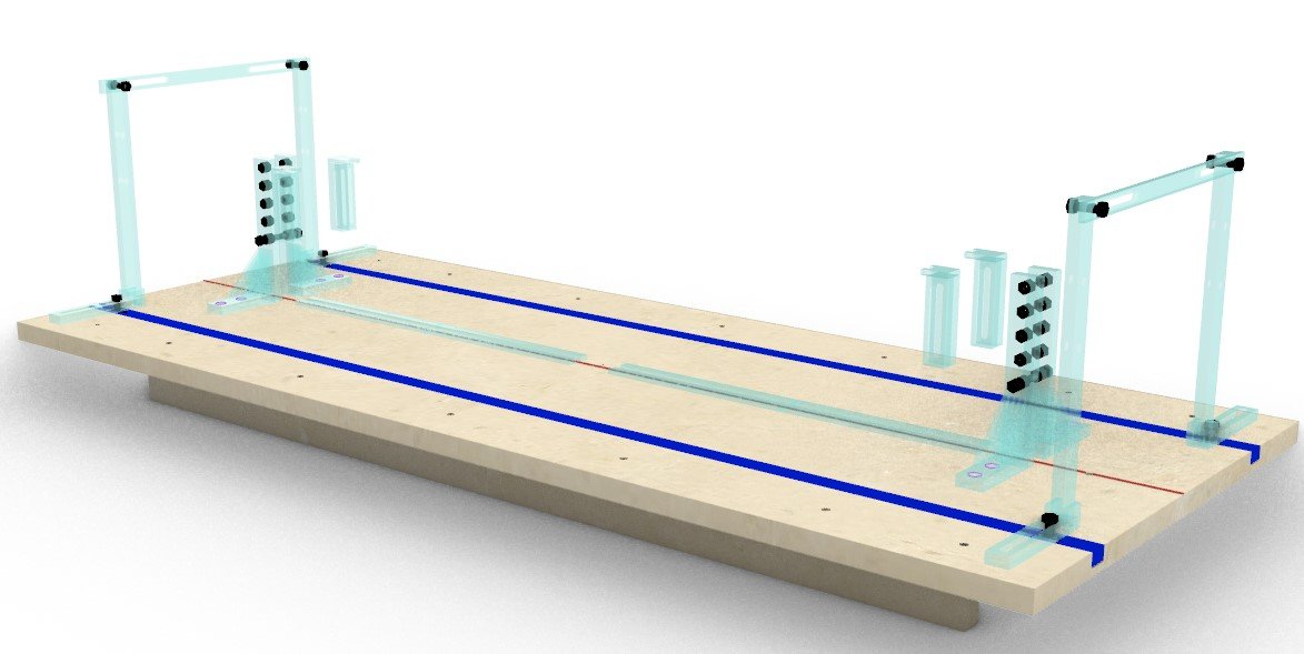
OK, I uploaded a PDF with table dimensions, a DXF with pieces prepared to be cut, usable for CNC (sorry, too much text to translate, but is MDF 22mm, plexiglass 5 and 10 mm) and the Rhino project (everything is in layers), including 2D What you need to pay attention to is the grooves - first find a suitable rail then set your groove to match it, slightly below the surface (I have about 0.5-1mm). Because the wood is quite heavy, I put the supports exactly below grooves - don't leave less than 5mm of wood below groove or you risk to break Also, you might want to adjust a bit hole sizes, for Imperial I prepared also some supports for keel which can be adjusted: In plan there are some holes, you don't need to drill them now, but I calculated so it can be used for building like this: Catalin Serafimescu - Masa Asamblare - CNC.dxf Masa asamblare.pdf Masa asamblare.3dm
-
@RickyGene - Is a customization of several building boards I saw here or other places, like the one used by Ed Tosti @Jonathan11 - I'm from Romania, it would be impossible to ship it for you. It should be easier for you to make it in US than I did here (for some reason it was really hard to find 22mm MDF) I will upload tomorrow the plan here as DXF and some pictures, so you don't have to deal with Rhino unless you want to modify it. The only thing you need to take care is the size of the rails - whatever you find you must match the grooves in the board. I
-
Thanks, Gary. I already saw your topic, I have an eye on it, maybe it helps me avoiding some mistakes
-
I wasn't completely lazy. I've finished rabbet line on both sides and I've made a building board, based on designs of Ed Tosti and others. Is quite versatile and lots of things can be adjusted. The size is big enough to accommodate bigger ships, like Young America or it can be used in methods using deck line supports (sorry, I can't remember how is called now) The keel can be hold using clamp-like ..or using a support, which can be adjusted up-down I have the project in Rhino, if anyone is interested. Is in metric (I used M3 and M6), but can be adjusted

-
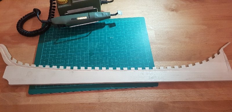
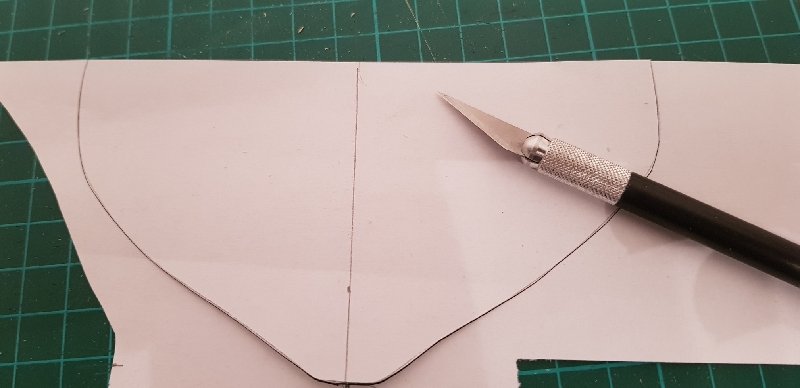
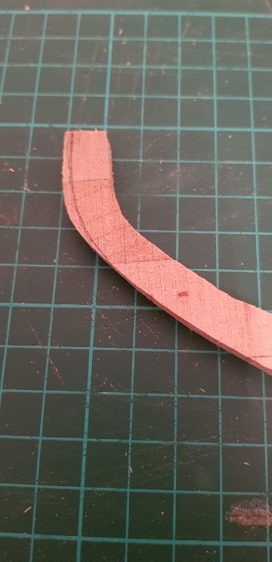
Normally this would be the moment to test fit the frames. Unfortunately the slots in keel are way too big than frame thickness and I didn't checked in advance. So I postponed this step until I will have everything else and I will be ready to permanently fix them. I will NOT test and glue them one by one, but once I test and fix with fillings all of them, I will not take them out to carry other operations, just glue them one by one, otherwise it would be almost impossible to match again fillings. I have cut rabbet line. Basswood is too soft for my taste. It split very easily. The cut is far from perfect, but I tried several techniques. First, cut a template for rabbet line on laser side BEFORE you cut it. Your life will be much easier. Alternatively, you can use carbon copy paper. First techniques was the one they recommend and the most obvious one: cut the bottom with a x-acto knife and then use a straight blade to remove material starting from bearding line. Pro: depending on your skills and patience the cut could be perfect. Cons:... or a disaster. You need a firm hand and lots of patience. There is a lot of material to remove. You'll need good, sharp blades. Is hard to make the a consistent 1/16" (1.6mm) deep cut, even doing several passes, as I found myself. 2nd technique was milling. Pro: the height (deep) of the cut is guaranteed. If you have the skills and can control the piece, you'll get a nice cut Cons: it might be hard to follow the curvature. Also, basswood is not easy to mill, is too soft. Can't go more than 0.5mm at once and the cut is not clean. So one side I cut it manually, then I passed it through mill to get a consistent deep cut. Them sand it again using a Proxxon micro pen, which proved very useful and can keep the bottom cut straight. The final result is not bad. It needs more sanding, but I will do it at the end. Now I'm afraid I'll take too much because the wood is so soft. I have also Jefferson Davis. I will apply the experience gained with America on it.
-
You are right, when I ordered the kit they told me they need to cut it. Also, from instructions seems to be 2 sets of frames, one numbered, other labeled.
-
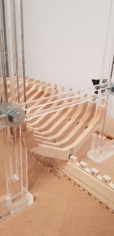
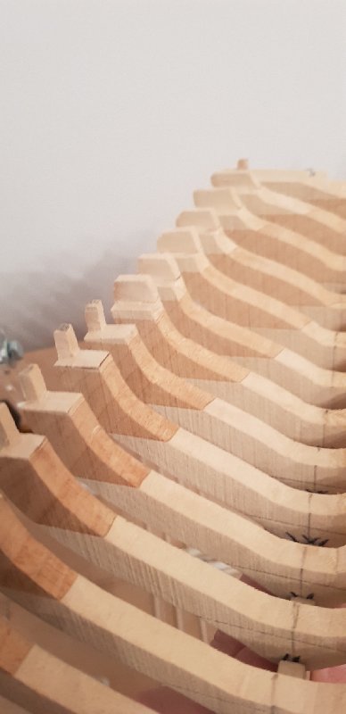
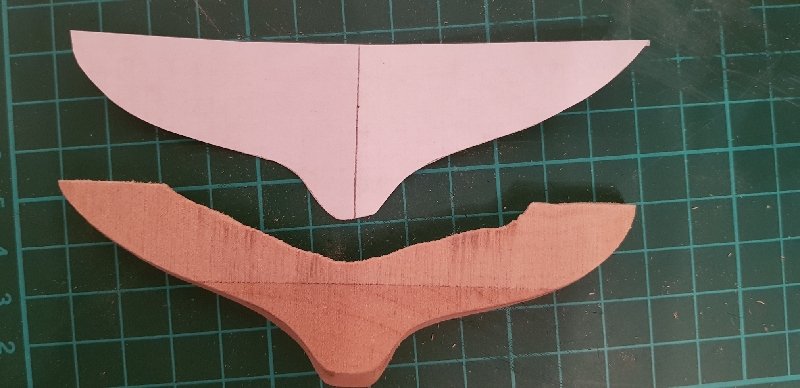
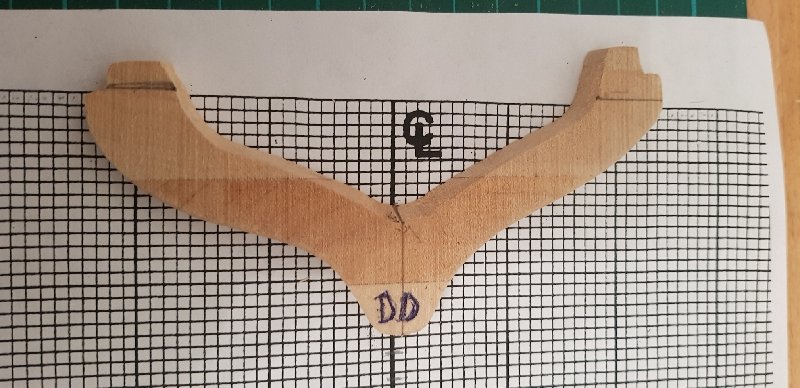
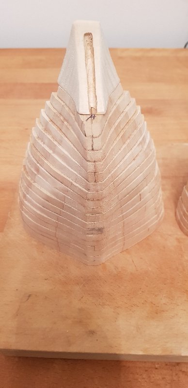
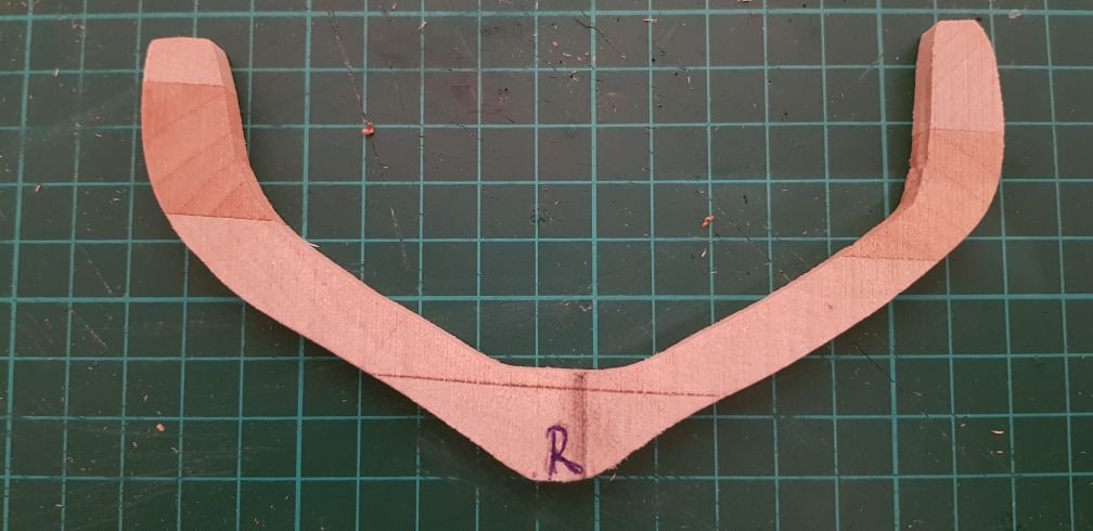
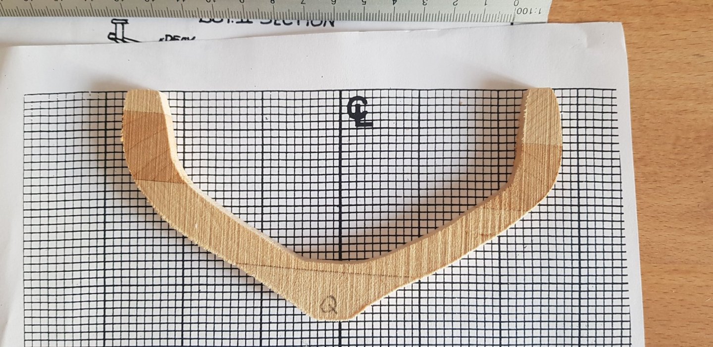
Slow progress, but I finished adjusting the frames. Thing is, I don't know at this time if the sizes are correct. I measured them from plan, aft side, but there are so much differences. If one expects same precision as laser-cut plywood, not the right place. My feeling is that the log was 'warped'; the aft side is much more asymmetrical and had a lot more material to be removed (I really hope I'm right!) The following photos are not following bearding line, but they show the discrepancies, mostly on stern half. I think the best thing is to leave enough 'meat' on the frames and sand them to proper dimension when fairing the hull. What I tried to do was to center the tops AND have the feet as symmetrical as possible, which is challenging because the frames seems warped. Advice: don't use the papers they provide, they are warped. Make yourself new ones and print enough of them. I measured on top of the paper but I used new templates; I found that if you have a proper drawing on paper you can cut it directly, but this doesn't work with what the provide because the lines are warped
-
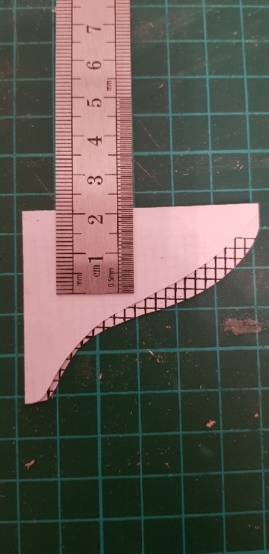
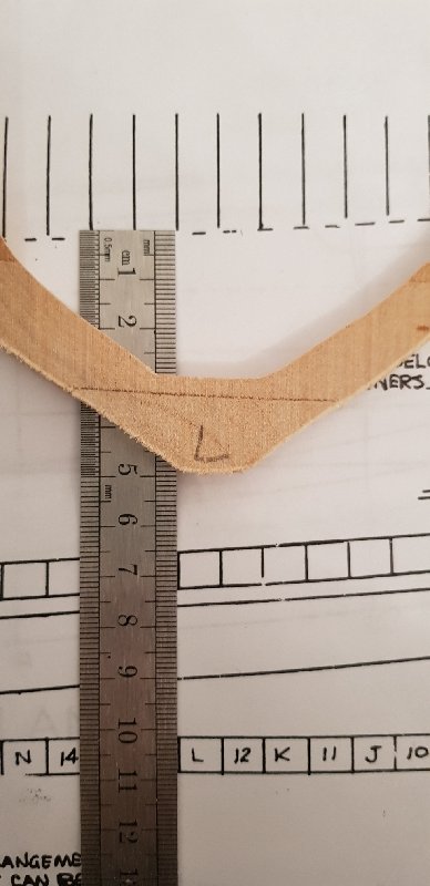
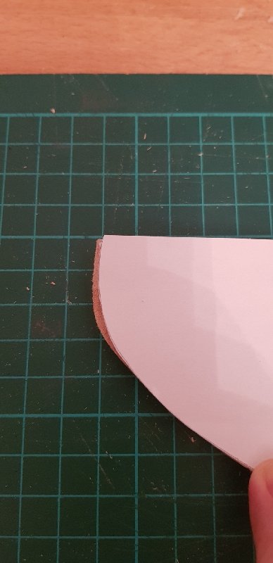
Yes, I think I found a way. Measure the height on plan Align shorter leg top, center then longer leg (red), simultaneously with lateral width (blue). Mark center on all sides. Mark and cut longer leg Make a template from paper, mark center, fold it carefully and see which side is smaller, then mark it on other side. Be careful, the frames are beveled, you template aft, then you mark aft - turn it before marking it. I think it goes pretty well, but the legs are not same width. Don't sand too much now

-
Hi Rick I intent to do a half-half, but I will decide once I finish framing Unfortunately both methods to determine the center are based on aligning top edges, but the result is not correct - see below - the heel would disappear completely. I will try this evening to see what is the right height and then I will adjust the top, then determine the center and make both sides symmetrical
-
Next is to ensure that frames are symmetrical. In theory I should align outside top edges and see where the middle is, but it seems that frames are way off. So I will perform this operation only when I'll have cut the notches in the keel, so I can check them against it
-
The keel and frames are made from basswood. Is easy to work with, but also is easy to grind too much. It seems I will use less power tools and more manual sanding. Also, it creates an INCREDIBLE amount of saw dust, very fine.
-
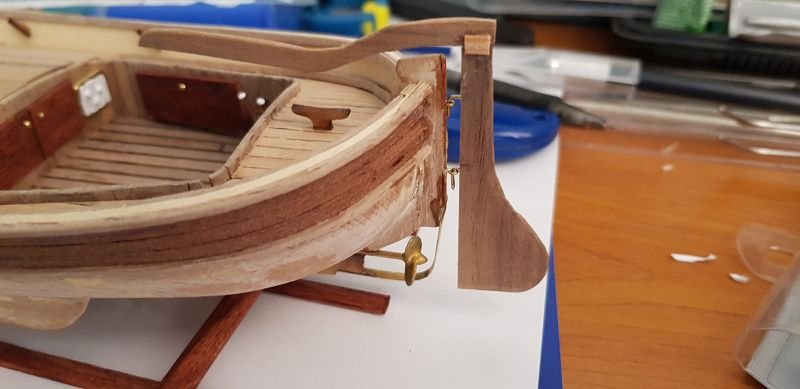
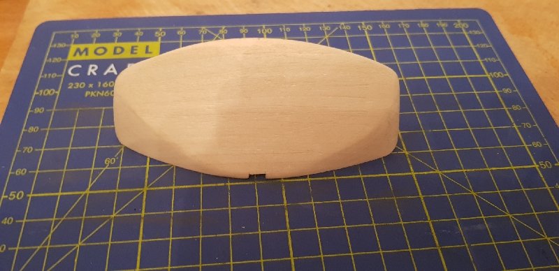
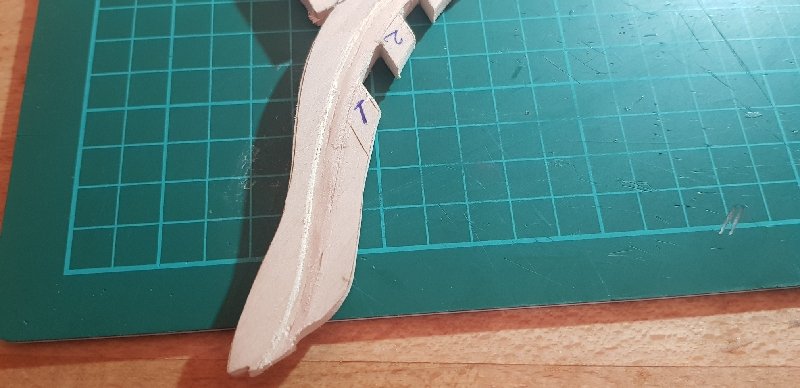
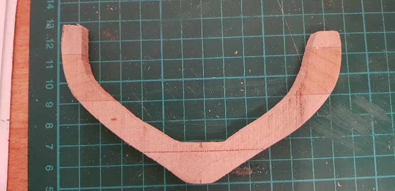
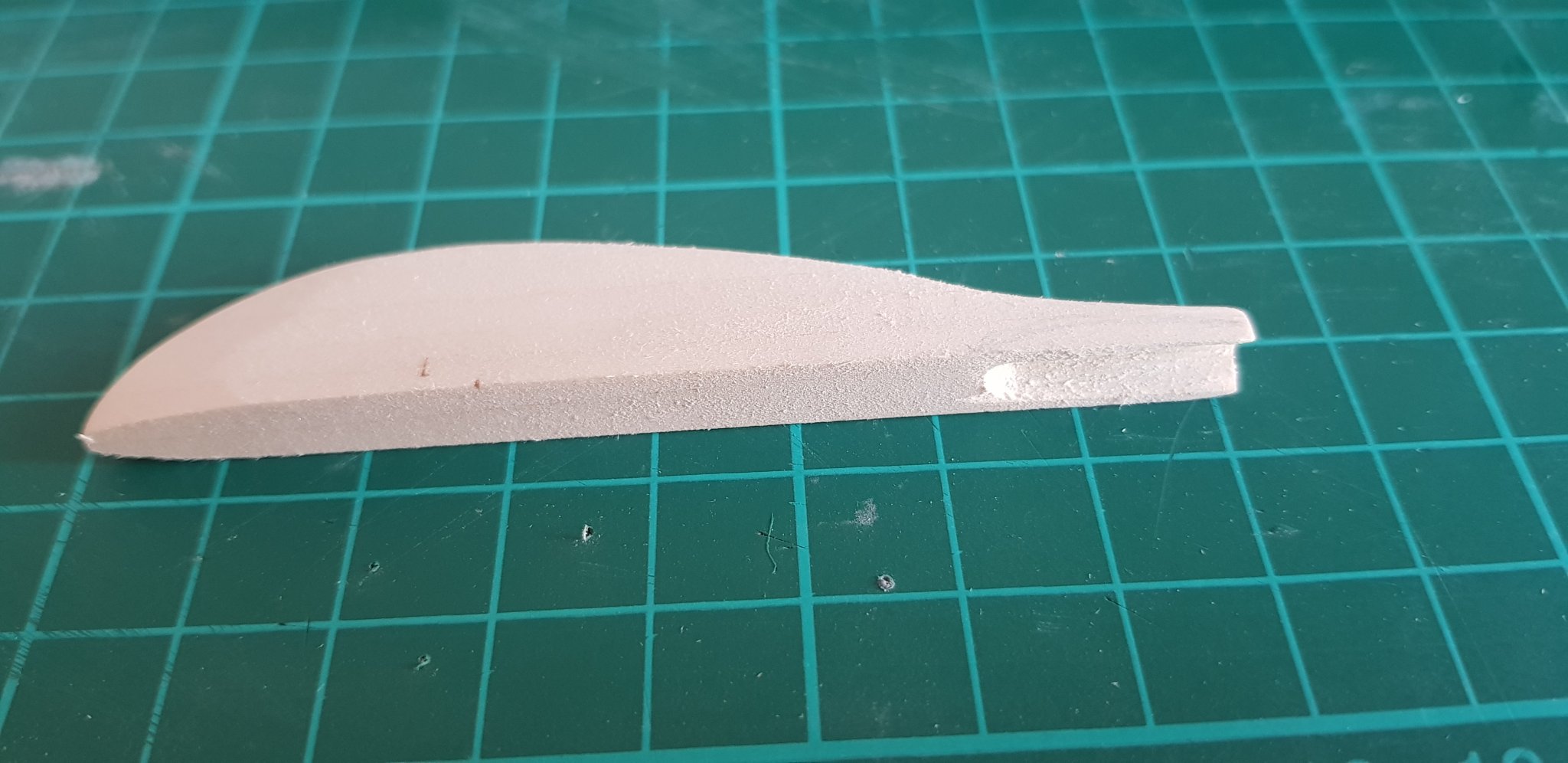
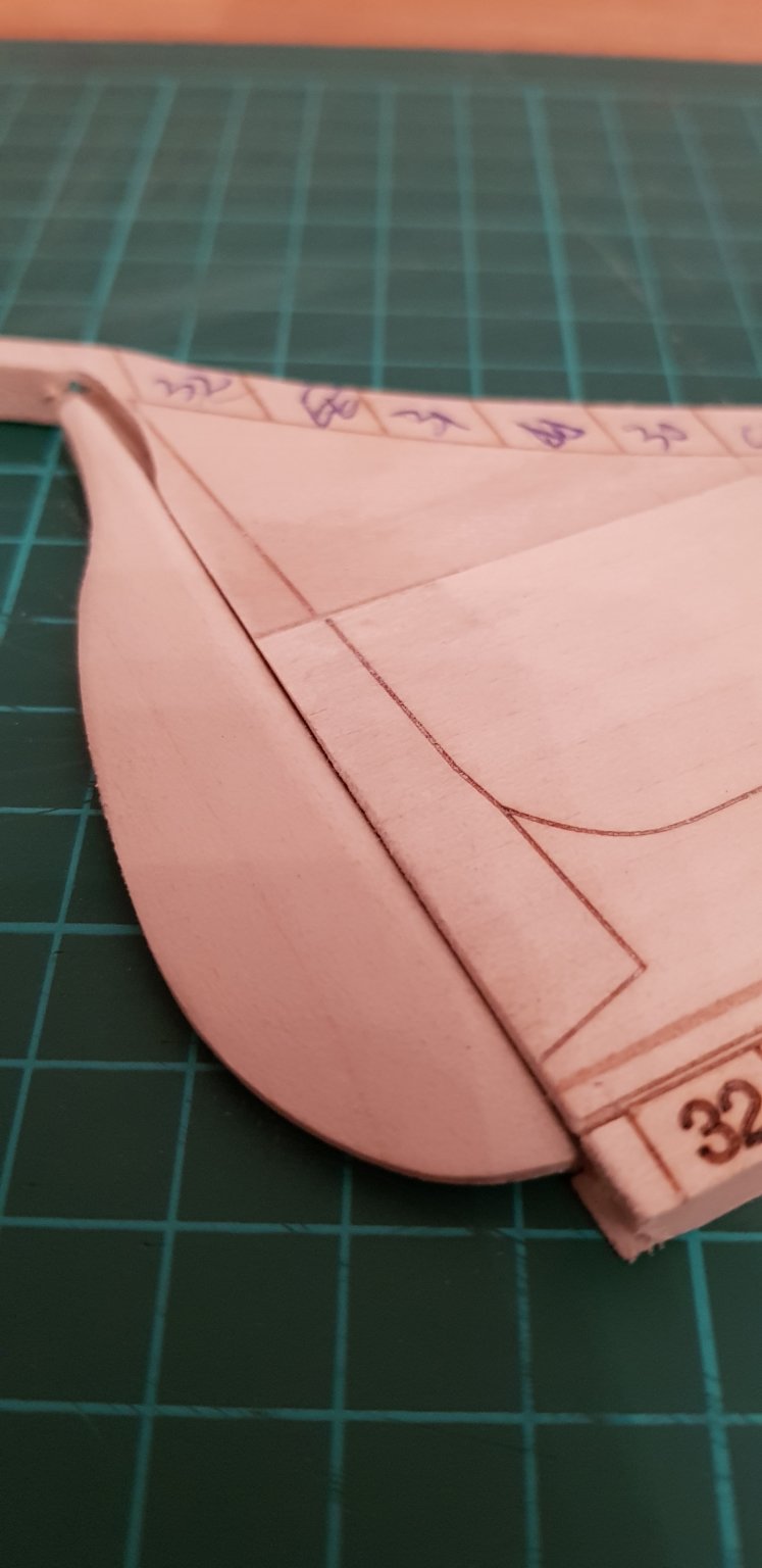
Shaped the rudder.


-
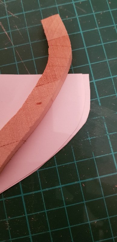
Started with keel, had to put together the 3 pieces. The cut lines are not on the edge of the board, so you need to take your time to fit it. Unfortunately, it doesn't seem that the laser marks match exactly the plan, so some adjustments has to be made along the way
.thumb.jpg.d984f1b0cf85c6484f0f08aabb6caef6.jpg)

-
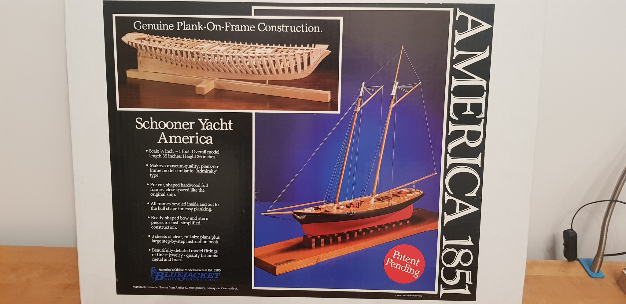
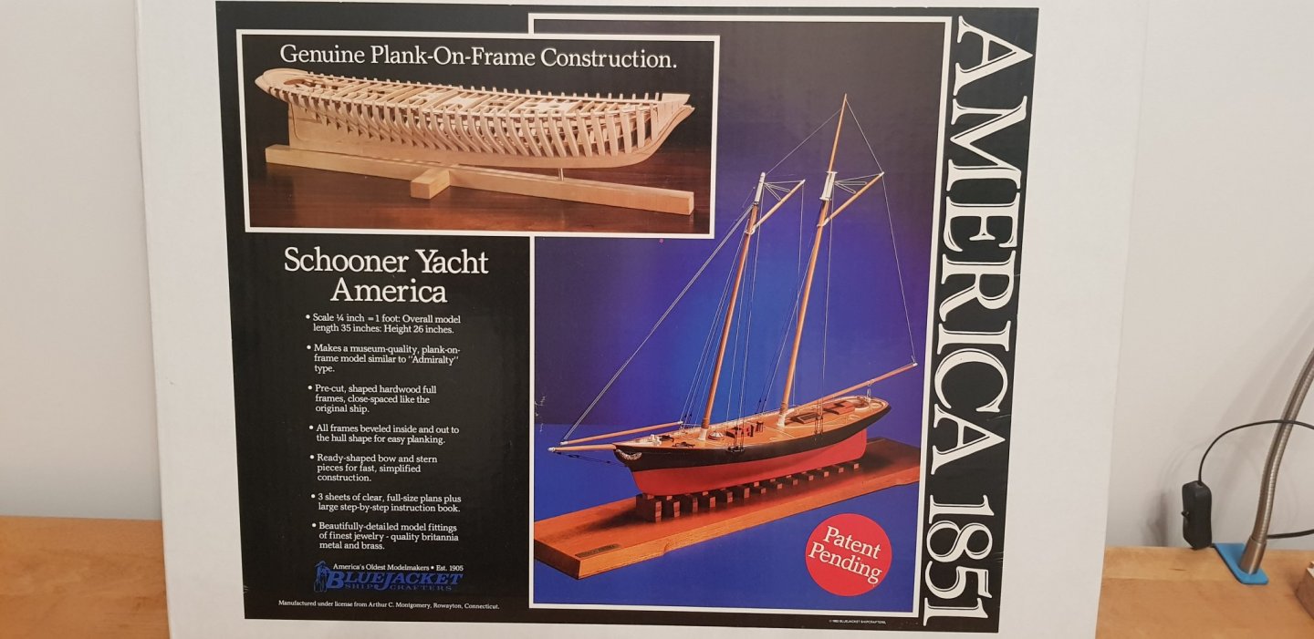
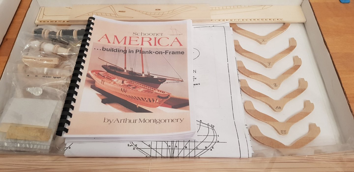
Got this kit from BlueJacket because I want to make transition to scratch built from kits. I hope it will help with some techniques, hopefully. The kit seems good, lots of material and fittings


.jpg.13d693ad08d781f0a1230f7ec6b0c490.jpg)